accessbase 2000 -startup (module 2) - learn nortek...
TRANSCRIPT

© 2008 Linear LLC. The information contained herein is subject to change without notice.
Software – Start Up
Created byPaul Jones
Technical Trainer
AccessBase 2000 - Startup (Module 2)

Linear AccessBase 2000
• The Startup consists of 5 easy steps.
1) Install Telephone Entry / Access Control Panel into AccessBase 2000 software
2) Configure Panel
3) Add Cardholder
4) Add Credential
5) Upload to Panel
Copyright © 2010 Linear LLC – P#1019 X1 Pg. 2
Step # 1 - Installing the Panel
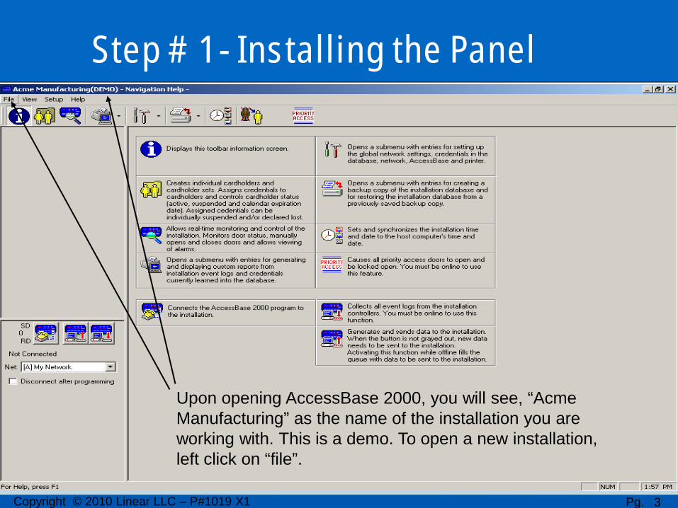
Upon opening AccessBase 2000, you will see, “Acme Manufacturing” as the name of the installation you are working with. This is a demo. To open a new installation, left click on “file”.
Copyright © 2010 Linear LLC – P#1019 X1 Pg. 3
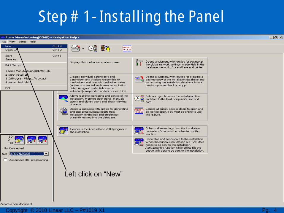
Left click on “New”
Step # 1 - Installing the Panel
Copyright © 2010 Linear LLC – P#1019 X1 Pg. 4
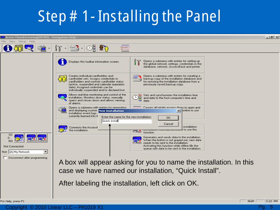
A box will appear asking for you to name the installation. In this case we have named our installation, “Quick Install”.
After labeling the installation, left click on OK.
Step # 1 - Installing the Panel
Copyright © 2010 Linear LLC – P#1019 X1 Pg. 5
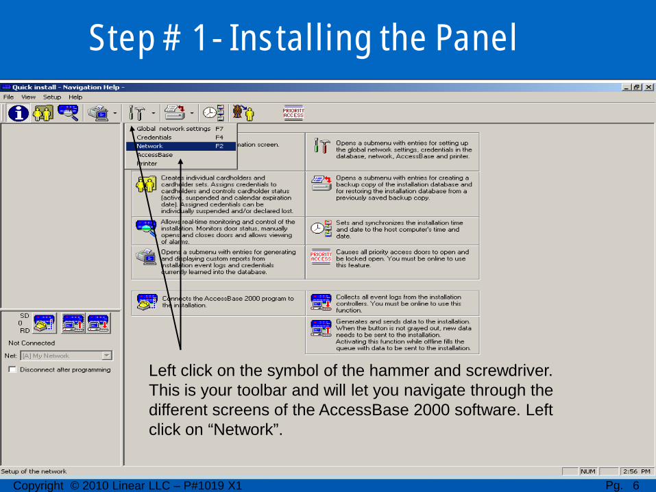
Left click on the symbol of the hammer and screwdriver. This is your toolbar and will let you navigate through the different screens of the AccessBase 2000 software. Left click on “Network”.
Step # 1 - Installing the Panel
Copyright © 2010 Linear LLC – P#1019 X1 Pg. 6

This is the network screen. The yellow telephones across the top of the screen,( A through H) represent the 8 different networks we can have with one installation.
The numbers 1 through 8 along the left side of the screen represent the 8 different panels, or “Nodes” we can have in each network. They can be any combination of the AE1000Plus, AE2000Plus, or the AM3 Plus panels. We will put our panel, or “Node” in network A, panel #1.
Step # 1 - Installing the Panel
Copyright © 2010 Linear LLC – P#1019 X1 Pg. 7

If we left click on the “A” yellow telephone for network “A”, the “Edit settings for this network” will appear. In the “connect using” box, we are directly connecting to the node using the RS232 port. In this computer we are using com port #1. We can choose between com ports 1 through 8, or select modem. If we are connecting using a modem, we would input the telephone number associated with the node in the, ”phone number” box. We then left click OK.
Step # 1 - Installing the Panel
Copyright © 2010 Linear LLC – P#1019 X1 Pg. 8

Using the, “On/Off line with installation” icon, left click on this icon and we will see the modem dialing the phone number screen, or opening com port screen. Once the software establishes communication with the node, you will see the node flash in the appropriate network. In this case we used com port #1, and the node, an AM3Plus, is flashing in network A, node #1. Left click on the flashing node.
Step # 1 - Installing the Panel
Copyright © 2010 Linear LLC – P#1019 X1 Pg. 9

After we left clicked on the flashing node, we have 3 options. Install panel, Download all memory, and Firmware Update. We want to left click on, “Install Panel”.
Step # 1 - Installing the Panel
Copyright © 2010 Linear LLC – P#1019 X1 Pg. 10
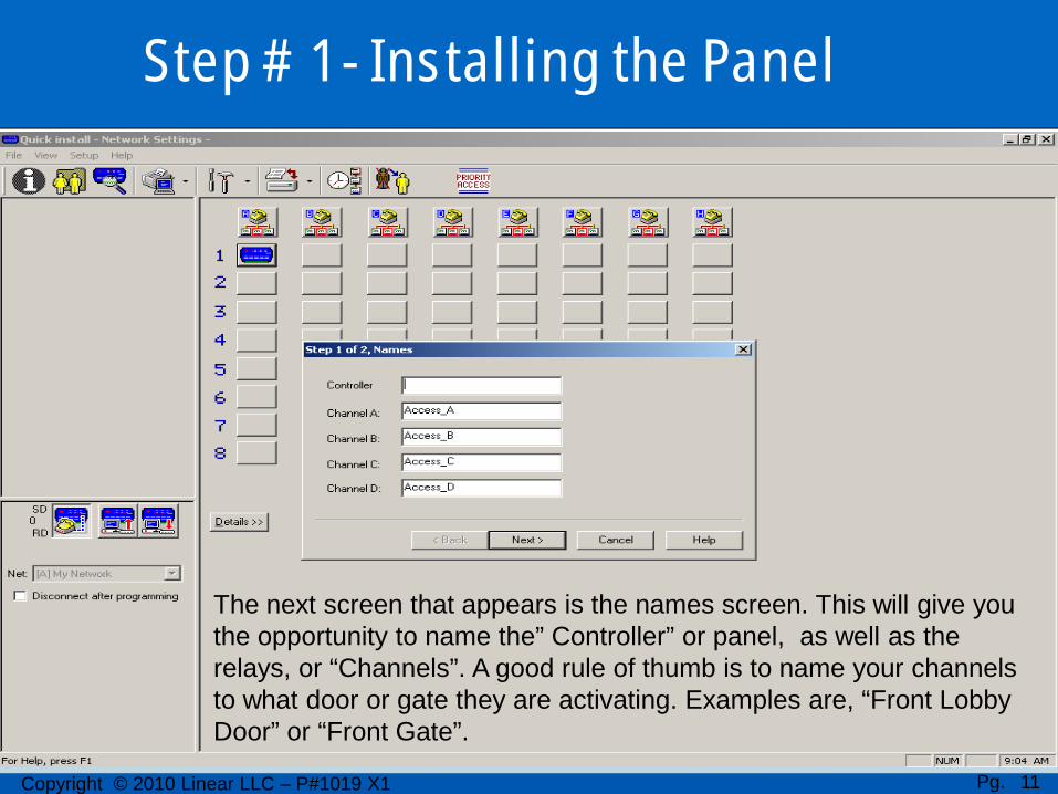
The next screen that appears is the names screen. This will give you the opportunity to name the” Controller” or panel, as well as the relays, or “Channels”. A good rule of thumb is to name your channels to what door or gate they are activating. Examples are, “Front Lobby Door” or “Front Gate”.
Step # 1 - Installing the Panel
Copyright © 2010 Linear LLC – P#1019 X1 Pg. 11

We have named our controller “AM-3” and our channels A and B “North Gate” and “South Gate” respectfully. We then left click on “Next”.
Step # 1 - Installing the Panel
Copyright © 2010 Linear LLC – P#1019 X1 Pg. 12
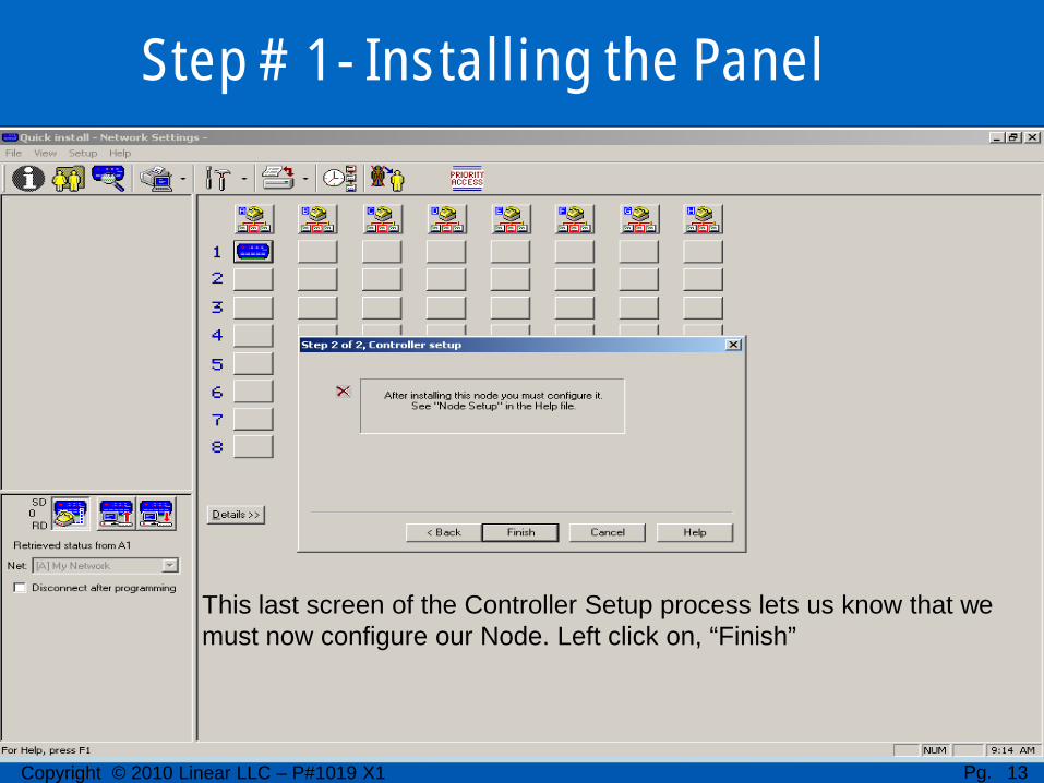
This last screen of the Controller Setup process lets us know that we must now configure our Node. Left click on, “Finish”
Step # 1 - Installing the Panel
Copyright © 2010 Linear LLC – P#1019 X1 Pg. 13

Notice that our node is now on steady, and not blinking. We have completed step 1 of the 5 step Quick Install program. We have installed our panel. We can now move on to Step 2. Configure Panel.
Step # 2 - Configuring the Panel
Copyright © 2010 Linear LLC – P#1019 X1 Pg. 14

Now, if we left click on our node, we have more options. In this training we will left click on, “Node Setup”. All the other options can be covered by using the Help menu, or will be covered in another training.
Step # 2 - Configuring the Panel
Copyright © 2010 Linear LLC – P#1019 X1 Pg. 15

This brings up the ,”Local Controller Settings” screen. We want to left click on the, ‘Remote Device” tab.
Step # 2 - Configuring the Panel
Copyright © 2010 Linear LLC – P#1019 X1 Pg. 16

This screen is where we link our remote devices to which relay we want that device to activate. Device or DV 1 through 6 are for ,”PBUS” inputs. DV 8 and 9 are for 26, 30 or 31 bit wiegand devices. Such as card readers. DV 7 is the keypad on the front of a telephone entry unit and cannot be changed. Control Channel lets us select which relay that device will activate. All other options can be covered by using the help menu, or will be covered in another training.
Step # 2 - Configuring the Panel
Copyright © 2010 Linear LLC – P#1019 X1 Pg. 17

We know that we have a keypad addressed as DV1 on the AM-KP keypad, so we select, “ Keypad” for DV1. We want that keypad to activate the North Gate which is wired to relay A. So we select relay A1A, or, “North Gate” in the Control Channel menu window.
Step # 2 - Configuring the Panel
Copyright © 2010 Linear LLC – P#1019 X1 Pg. 18

We also have a card reader wired to Reader A or the DV8 input on the AM-3 panel. Our cards are 26 bit so we select, “Wiegand 26” for DV8. We want that card reader to activate relay B or, “South Gate”. So we select A1B, South Gate in the Control Channel menu bar. We then left click on the “Apply” button. We have now completed step 2,Configureing the Panel.
Step # 2 - Configuring the Panel
Copyright © 2010 Linear LLC – P#1019 X1 Pg. 19

To continue to step 3, Add Cardholder, we need to go to the cardholder screen. To get to the cardholder screen, left click on the 2 yellow figures icon in the upper left corner of this screen
Step # 3 – Adding a Cardholder
Copyright © 2010 Linear LLC – P#1019 X1 Pg. 20

In the Cardholder screen, we have 2 cardholder sets. All Access, and No Access. It is important to know that cardholders are added to cardholder sets, so that every cardholder in that set will have the same access levels or, “Validation Groups”. We can create our own cardholder sets, but for the Startup, we will add a cardholder to the All Access set.
To create a new Cardholder Set, left click on the two yellow figures with the green plus sign.
Validation Groups or (Access Levels) can be assigned at a later time and are covered in Module Four.
Step # 3 – Adding a Cardholder
Copyright © 2010 Linear LLC – P#1019 X1 Pg. 21

If we left click on the on the All Access cardholder set, we can see that a single yellow person with a green plus sign icon appears. This icon is used to add our first cardholder
Step # 3 – Adding a Cardholder
Copyright © 2010 Linear LLC – P#1019 X1 Pg. 22

If we left click on the add cardholder icon, we see a single green figure icon appear below the all access cardholder set. This is our first cardholder
Step # 3 – Adding a Cardholder
Copyright © 2010 Linear LLC – P#1019 X1 Pg. 23

If we left click on that single green cardholder icon, the cardholders information screen appears. For the Startup, we will give this cardholder a first and last name, and a home phone number
Step # 3 – Adding a Cardholder
Copyright © 2010 Linear LLC – P#1019 X1 Pg. 24

We have named our card holder John Linear, and given him a phone number of 1231234. We left click on, “Apply”. We have now completed step 3, Add Cardholder, of the 5 step process. Next, we will move onto step 4, Add Credential.
Step # 3 – Adding a Cardholder
Copyright © 2010 Linear LLC – P#1019 X1 Pg. 25

If we look in the Credentials box, we can see that we can add Transmitters, Cards, Entry Codes and Directory Codes. We will add an Entry Code as well as an Access Card. To add an Entry Code, we simply left click on the Entry Code button
Step # 4 –Adding Credentials
Copyright © 2010 Linear LLC – P#1019 X1 Pg. 26

When we left click on the Entry Code button, the Assign Entry Code screen appears. Left click in the Entry Code box, and type in the entry code we want to give to the cardholder. In this case we have assigned 1234. Then we left click on Assign. The entry code can be 2 to 8 digits in length.
Step # 4 –Adding Credentials
Copyright © 2010 Linear LLC – P#1019 X1 Pg. 27

We now see that the entry code has been assigned, and an icon of a keypad appears next to the Entry Code button. Next we will add an Access Card.
Step # 4 –Adding Credentials
Copyright © 2010 Linear LLC – P#1019 X1 Pg. 28

If we left click on the Cards button, we see the Assign Card screen appear, but we also see a new button available. The “Assign New Individual Card” button. This is the button we will use for our Startup program. Left click on that button.
Step # 4 –Adding Credentials
Copyright © 2010 Linear LLC – P#1019 X1 Pg. 29

On each card there will be a number from 1 to 5 digits in length, telling you what the code is for that card. On our card, the number 10,000 was on the card, so we typed 10000 into the Card ID box. Facility codes can be covered by using the help menu and are not covered in this Module, so that is all we type in, and we left click OK.
Step # 4 –Adding Credentials
Copyright © 2010 Linear LLC – P#1019 X1 Pg. 30

We can now see that the cardholder has an access card assigned to him, and we left click on the Apply button. If we wanted to add transmitters, or if we have a telephone entry unit, directory codes, they would be added in the same fashion. We have now completed step 4 of the 5 step process. Finally we will upload to the AM3Plus panel. This is the step that programs all the information into the panel.
Step # 4 –Adding Credentials
Copyright © 2010 Linear LLC – P#1019 X1 Pg. 31

We will occasionally see red flashes next to the SD and RD icons. This is normal and means the panel is communicating properly. On the right hand side of the On/Off line icon, we see an icon that has a red arrow pointing up. This is our upload button. Left click on this button.
Step # 5 – Uploading to the Panel
Copyright © 2010 Linear LLC – P#1019 X1 Pg. 32

Once we left click on the upload button, we will see a number appear between the SD and RD icons. This is the number of data packets the AccessBase2000 software is sending to the panel. That number will begin to countdown. When that number reaches zero, the Startup process is complete.
Step # 5 – Uploading to the Panel
Copyright © 2010 Linear LLC – P#1019 X1 Pg. 33

We can now put a checkmark into the Disconnect after programming box, and note the upload button is now grayed out. That lets us know that all of the information has been sent to the panel, and the system is ready for testing.
Step # 5 – Uploading to the Panel
Copyright © 2010 Linear LLC – P#1019 X1 Pg. 34

© 2008 Linear LLC. The information contained herein is subject to change without notice.
For other Related Product Webinars and Presentations (Mod #1 – AccessBase 2000 Basics, Mod #3 – AccessBase 2000 Adding Cardholders & Credentials, and Mod #4 -AccessBase 2000 Validation Groups) or, for a list of all pre-recorded webinars and other training opportunities visit us at www.LearnLinear.com.
For more information on sales of Linear Electronic Systems or products, please visit us at http://www.linearcorp.com/iei_access_sales.php or for information on all Linear products and services, please visit our home page at www.linearcorp.com.
To locate a Dealer in your area to purchase a Linear product, please visit http://www.linearcorp.com/dealers.php
This Completes the Access section; Start Up (Module 2)
Pg. 35Copyright © 2010 Linear LLC – P#1019 X1