accessories akl suspension clamps - dxdlw · suspension clamps these clamps are designed to be used...
TRANSCRIPT
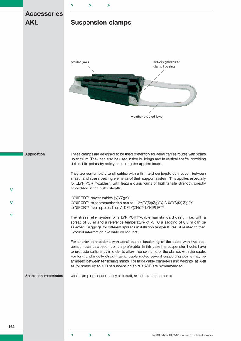
Suspension clamps
These clamps are designed to be used preferably for aerial cables routes with spansup to 50 m. They can also be used inside buildings and in vertical shafts, providingdefined fix points by safely accepting the applied loads.
They are contemplary to all cables with a firm and conjugate connection betweensheath and stress bearing elements of their support system. This applies especiallyfor „LYNIPORT®-cables“, with feature glass yarns of high tensile strength, directlyembedded in the outer sheath.
LYNIPORT®-power cables (N)YZg2YLYNIPORT®-telecommunication cables J-2Y2Y(St)(Zg)2Y, A-02YS(St)(Zg)2YLYNIPORT®-fiber optic cables A-DF2Y(ZN)2Y-LYNIPORT®
The stress relief system of a LYNIPORT®-cable has standard design, i.e. with a spread of 50 m and a reference temperature of -5 °C a sagging of 0,5 m can beselected. Saggings for different spreads installation temperatures ist related to that.Detailed information available on request.
For shorter connections with aerial cables tensioning of the cable with two sus-pension clamps at each point is preferable. In this case the suspension hooks haveto protrude sufficiently in order to allow free swinging of the clamps with the cable.For long and mostly straight aerial cable routes several supporting points may bearranged between tensioning masts. For large cable diameters and weights, as wellas for spans up to 100 m suspension spirals ASP are recommended.
wide clamping section, easy to install, re-adjustable, compact
AccessoriesAKL
FACAB LYNEN TK 03/03 - subject to technical changes
162
weather proofed jaws
profiled jaws hot-dip galvanizedclamp housing
Application
Special characteristics
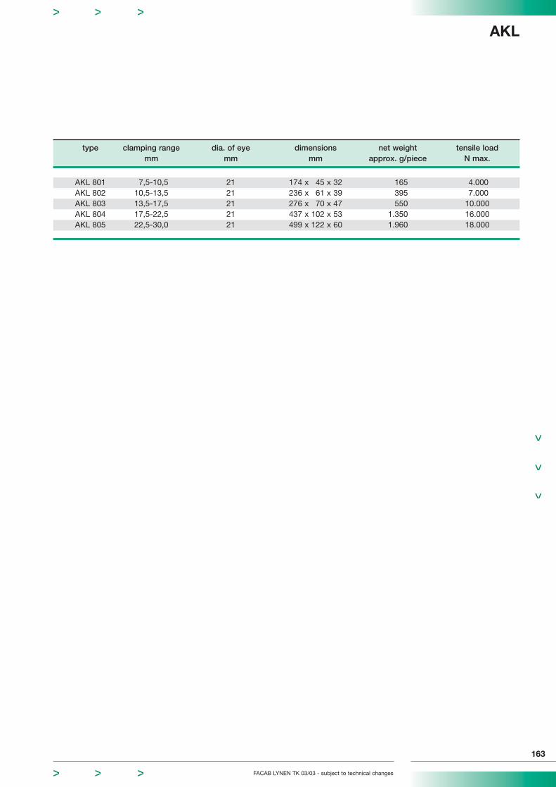
type clamping range dia. of eye dimensions net weight tensile loadmm mm mm approx. g/piece N max.
AKL 801 7,5-10,5 21 174 x 45 x 32 165 4.000AKL 802 10,5-13,5 21 236 x 61 x 39 395 7.000AKL 803 13,5-17,5 21 276 x 70 x 47 550 10.000AKL 804 17,5-22,5 21 437 x 102 x 53 1.350 16.000AKL 805 22,5-30,0 21 499 x 122 x 60 1.960 18.000
FACAB LYNEN TK 03/03 - subject to technical changes
AKL
163

Table 1
Colour core code – to DIN 47100
1 white 9 black 17 white-grey 25 white-black 33 green-red 41 grey-black
2 brown 10 violet 18 grey-brown 26 brown-black 34 yellow-red 42 pink-black
3 green 11 grey-pink 19 white-pink 27 grey-green 35 green-black 43 blue-black
4 yellow* 12 red-blue 20 pink-brown 28 yellow-grey 36 yellow-black 44 red-black
5 grey 13 white-green 21 white-blue 29 pink-green 37 grey-blue From 45 coresonwards repetition
6 pink 14 blue-green 22 brown-blue 30 yellow-pink 38 pink-blue of colours
7 blue 15 white-yellow 23 white-red 31 green-blue 39 grey-red
8 red 16 yellow-brown 24 brown-red 32 yellow-blue 40 pink-red
Note: Also available in type -JZ and -OZ*An exception is the 4 core cable. Colour code: white, yellow, brown, blue.
Table 2
The identification of the core is done by ring marking
circuit 1 a-core without rings
b-core rings width approx. 2 mm
circuit 2 a-core
b-core
Basic colours of the core insulation sheath of 5 star quads of a bundle:1th quad red – 2nd quad green – 3rd quad grey – 4th quad yellow – 5th quad whiteThe tracer bundles are marked by a red helix.
Annex AIdentification of copper, telecom and data cables
164
FACAB LYNEN TK 03/03 - subject to technical changes
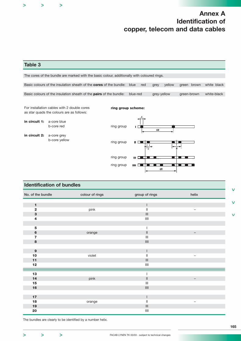
Table 3
The cores of the bundle are marked with the basic colour, additionally with coloured rings.
Basic colours of the insulation sheath of the cores of the bundle: blue red grey yellow green brown white black
Basic colours of the insulation sheath of the pairs of the bundle: blue-red grey-yellow green-brown white-black
For installation cables with 2 double coresas star quads the colours are as follows:
in circuit 1: a-core blueb-core red
in circuit 2: a-core greyb-core yellow
FACAB LYNEN TK 03/03 - subject to technical changes
Annex AIdentification of
copper, telecom and data cables
165
ring group scheme:
ring group
ring group
ring group
ring group
Identification of bundles
No. of the bundle colour of rings group of rings helix
1 I2 pink II –3 III4 IIII
5 I6 orange II –7 III8 IIII
9 I10 violet II –11 III12 IIII
13 I14 pink II –15 III16 IIII
17 I18 orange II –19 III20 IIII
The bundles are clearly to be identified by a number helix.
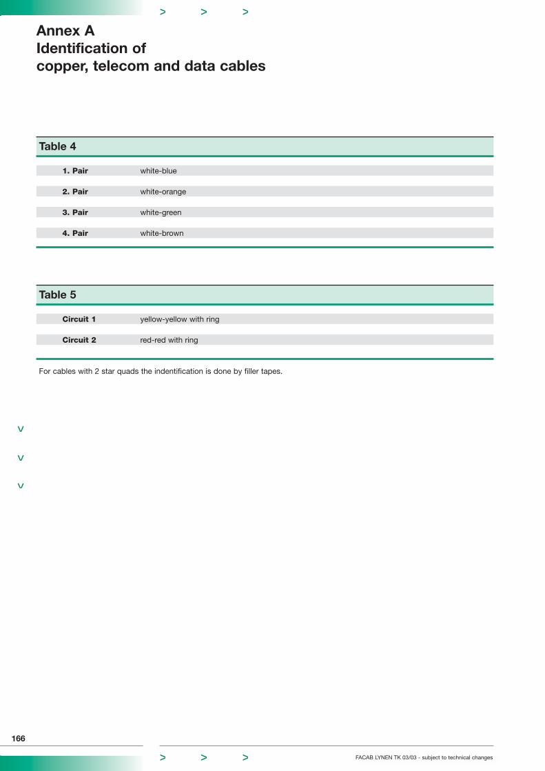
Table 4
1. Pair white-blue
2. Pair white-orange
3. Pair white-green
4. Pair white-brown
Table 5
Circuit 1 yellow-yellow with ring
Circuit 2 red-red with ring
For cables with 2 star quads the indentification is done by filler tapes.
Annex AIdentification of copper, telecom and data cables
166
FACAB LYNEN TK 03/03 - subject to technical changes

Table 6
Flexible power cables – to DIN VDE 0293Core identification of multicore flexible cables
No. of cores cables with a cables withoutgreen-yellow conductor green-yellow conductor
2 -- brown, blue3 green-yellow, brown, blue black, blue, brown4 green-yellow, black, blue, brown black, blue, brown, black5 green-yellow, black, blue, brown, black black, blue, brown, black, black
6 and more green-yellow, all other cores black with numbers printed on all cores black with numbers printed on
Table 7
Power cables – to DIN VDE 0293Core identification of multicore cables for fixed installations
No. of with green-yellow without green-yellow with concentriccores conductor conductor conductor
2 green-yellow, black black, blue black, blue3 green-yellow, black, blue black, blue, brown black, blue, brown4 green-yellow, black, blue, brown black, blue, brown, black black, blue, brown, black5 green-yellow, black, blue, brown, black black, blue, brown, black, black all cores black with numbers on it6 green-yellow, all other cores black all cores black all cores black
and more with numbers printed on with numbers printed on with numbers printed on
FACAB LYNEN TK 03/03 - subject to technical changes
Anhang AIdentification of
power cables
167
Table 8
Possible colour code – acc. to DIN VDE 0293
0 green-yellow 6 pink1 black 7 orange2 blue 8 white3 brown 9 red4 grey 10 turquoise5 violet
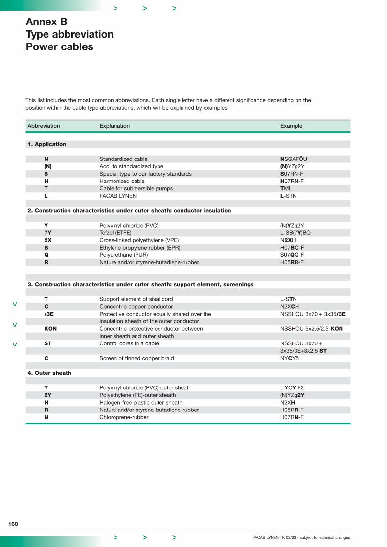
Abbreviation Explanation Example
1. Application
N Standardized cable NSGAFÖU(N) Acc. to standardized type (N)YZg2YS Special type to our factory standards S07RN-FH Harmonized cable H07RN-FT Cable for submersible pumps TMLL FACAB LYNEN L-STN
2. Construction characteristics under outer sheath: conductor insulation
Y Polyvinyl chloride (PVC) (N)YZg2Y7Y Tefzel (ETFE) L-SB(7Y)BQ2X Cross-linked polyethylene (VPE) N2XHB Ethylene propylene rubber (EPR) H07BQ-FQ Polyurethane (PUR) S07QQ-FR Nature and/or styrene-butadiene-rubber H05RR-F
3. Construction characteristics under outer sheath: support element, screenings
T Support element of sisal cord L-STNC Concentric copper conductor N2XCH/3E Protective conductor equally shared over the NSSHÖU 3x70 + 3x35/3E
insulation sheath of the outer conductorKON Concentric protective conductor between NSSHÖU 5x2,5/2,5 KON
inner sheath and outer sheathST Control cores in a cable NSSHÖU 3x70 +
3x35/3E+3x2,5 STC Screen of tinned copper braid NYCYö
4. Outer sheath
Y Polyvinyl chloride (PVC)-outer sheath LiYCY F22Y Polyethylene (PE)-outer sheath (N)YZg2YH Halogen-free plastic outer sheath N2XHR Nature and/or styrene-butadiene-rubber H05RR-FN Chloroprene-rubber H07RN-F
Annex BType abbreviationPower cables
168
FACAB LYNEN TK 03/03 - subject to technical changes
This list includes the most common abbreviations. Each single letter have a different significance depending on the position within the cable type abbreviations, which will be explained by examples.
FACAB LYNEN TK 03/03 - subject to technical changes
Annex BType abbreviation
Power cables
169
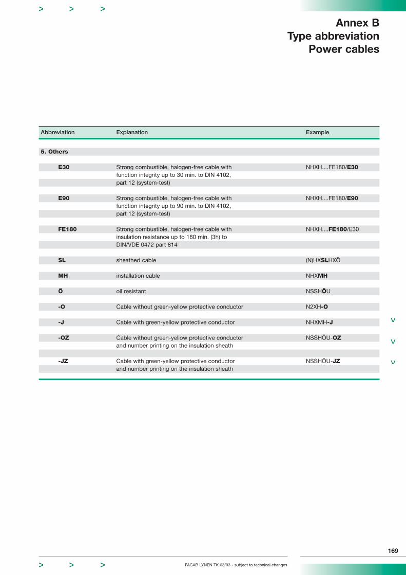
Abbreviation Explanation Example
5. Others
E30 Strong combustible, halogen-free cable with NHXH....FE180/E30function integrity up to 30 min. to DIN 4102,part 12 (system-test)
E90 Strong combustible, halogen-free cable with NHXH....FE180/E90function integrity up to 90 min. to DIN 4102,part 12 (system-test)
FE180 Strong combustible, halogen-free cable with NHXH....FE180/E30insulation resistance up to 180 min. (3h) toDIN/VDE 0472 part 814
SL sheathed cable (N)HXSLHXÖ
MH installation cable NHXMH
Ö oil resistant NSSHÖU
-O Cable without green-yellow protective conductor N2XH-O
-J Cable with green-yellow protective conductor NHXMH-J
-OZ Cable without green-yellow protective conductor NSSHÖU-OZand number printing on the insulation sheath
-JZ Cable with green-yellow protective conductor NSSHÖU-JZand number printing on the insulation sheath
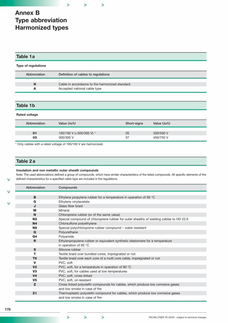
Table 1a
Type of regulations
Abbreviation Definition of cables to regulations
H Cable in accordance to the harmonized standardA Accepted national cable type
Table 1b
Rated voltage
Abbreviation Value Uo/U Short-signs Value Uo/U
01 100/100 V (<300/300 V) 1) 05 300/500 V03 300/300 V 07 450/750 V
1) Only cables with a rated voltage of 100/100 V are harmonized.
Table 2 a
Insulation and non metallic outer sheath compoundsNote: The used abbreviations defined a group of compounds, which have similar characteristics of the listed compounds. All specific elements of thedefined characteristics for a specified cable type are included in the regulations.
Abbreviation Compounds
B Ethylene propylene rubber for a temperature in operation of 90 °CG Ethylene vinylacetateJ Glass fiber braidM MineralN Chloroprene rubber (or of the same value)N2 Special compound of chloroprene rubber for outer sheaths of welding cables to HD 22.6N4 Chlorsulfone polyethyleneN8 Special polychloroprene rubber compound – water resistantQ PolyurethaneQ4 PolyamideR Ethylenpropylene rubber or equivalent synthetic elastomere for a temperature
in operation of 60 °CS Silicone rubberT Textile braid over bundled cores, impregnated or notT6 Textile braid over each core of a multi core cable, impregnated or notV PVC, softV2 PVC, soft, for a temperature in operation of 90 °CV3 PVC, soft, for cables used at low temperaturesV4 PVC, soft, cross linkedV5 PVC, soft, oil resistantZ Cross linked polyolefin compounds for cables, which produce low corrosive gases
and low smoke in case of fireZ1 Thermoplastic polyolefin compound for cables, which produce low corrosive gases
and low smoke in case of fire
170
FACAB LYNEN TK 03/03 - subject to technical changes
Annex BType abbreviationHarmonized types
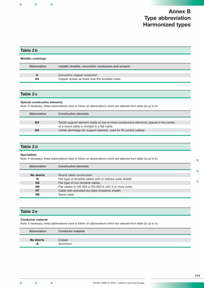
Table 2 b
Metallic coverings
Abbreviation metallic sheaths, concentric conductors and screens
C Concentric copper conductorC4 Copper screen as braid over the bundled cores
Table 2 c
Special constructive elementsNote: If necessary, these abbreviations have to follow on abbreviations which are selected from table 2a up to 2c
Abbreviation Constructive elements
D3 Textile support element made of one or more constructive elements, placed in the center of a round cable or divided in a flat cable.
D5 Center shrinkage (no support element, used for lift control cables)
Table 2 e
Conductor materialNote: If necessary, these abbreviations have to follow on abbreviations which are selected from table 2a up to 2c.
Abbreviation Conductor material
No shorts Copper-A Aluminium
Table 2 d
SpecialitiesNote: If necessary, these abbreviations have to follow on abbreviations which are selected from table 2a up to 2c.
Abbreviation Constructive elements
No shorts Round cable constructionH Flat type of divisible cables with or without outer sheathH2 Flat type of non divisible cablesH6 Flat cables to HD 359 or EN 50214 with 3 or more coresH7 Cable with extruded two layer insulation sheathH8 Spiral cable
FACAB LYNEN TK 03/03 - subject to technical changes
171
Annex BType abbreviationHarmonized types

172
FACAB LYNEN TK 03/03 - subject to technical changes
Table 2 f
Conductor shapeNote: These abbreviations must follow the abbreviations after a dash (in case of aluminium conductors already included in the
abbreviation A), which have been chosen out of the tables 2a up to 2e. For cable types with conductors of different shapes only the abbreviation for the shape of the outer conductor must be shown.
Abbreviation Conductor shape
-D Fine stranded conductor for welding cables to HD 22.6(Flexibility divergent to HD 383 class 5)
-E Very fine stranded conductor for welding cables to HD 22.6(Flexibility divergent to HD 383 class 6)
-F Fine stranded conductor of a flexible cable(Flexibility to HD 383 class 5)
-H Very fine stranded conductor of a flexible cable(Flexibility to HD 383 class 6)
-K Fine stranded conductor of a cable for fixed installation(If nothing other is required. Flexibility to HD 383 class 5)
-R Multi stranded round conductor-U Solid round conductor-Y Lahn stranded conductor
Table 3
Number of cores and nominal cross section of conductors
Abbreviation Number and nominal cross section of conductors
(Figure) Number, n, of coresx Sign for cable types without green-yellow coreG Sign for cable types with green-yellow core
(Figure)*) Nominal cross section s, of conductors in mm2
Y Lahn stranded conductor, whose nominal cross section is not determined.
*) It is an option for the countries to add the short “N” for the core indentificationwith figures (behind the nominal cross section)
General examples
nxs oder nGs n cores of s mm2 nominal cross sectionn1xs1 + n2xs2 n1 cores of s1 mm2 nominal cross section + n2 cores of s2 mm2 nominal cross sectionnxs1/s2 n cores of s1 mm2 nominal cross section and concentric conductor of s2 mm2 nominal cross sectionn1xs1 n1 cores of s1 mm2 nominal cross section + n2 cores of s2 mm2 nominal cross section+ n2xs2/s3 and concentric conductor of s3 mm2 nominal cross section
Annex BType abbreviationHarmonized types

FACAB LYNEN TK 03/03 - subject to technical changes
173
Basic elements of type abbreviations
The type abbreviation must be composed of three parts, which characterize the essential characteristics of a cable:
Part Basic elements of type abbreviations see table(s)
1 Reference to standards 1aRated voltage 1b
2 Construction of a cable always in radial steps,started with the insulation compound 2a up to 2dthen after a dash compoundand shape of conductor(s) 2e and 2f
3 Number and nominal cross section of conductors
Part 1 and 2 of the abbreviations were always written without a gap and create the abbreviation of the cable version of a cable.Part 3 of the abbreviation include specific characteristics for the number of cores and the nominal cross section of a conductor, if required.
A overview of abbreviations and her sequence are listed in table 4.
If two or more abbreviations, which are listed in same column of table 4, have to be used in a specific type abbreviation then theyhave to be marked in radial steps, starting with the core resp. conductor axis.
Practical examples
4 G 50 Four core cable with green-yellow core and nominal cross section of 50 mm2
4 x 50 Four core cable without green-yellow core and nominal cross section of 50 mm2
3 x 50 + 1G25 Four core cable with 3 conductors of nominal cross section of 50 mm2 and a green-yellow core, which has a reduced conductor of 25 mm2 nominal cross section
3 x 70/35 Three core cable with nominal cross section of 70 mm2 and with concentric conductor of 35 mm2 nominal cross section
2 x Y Two core cable with lahn stranded conductors
Annex BType abbreviationHarmonized types
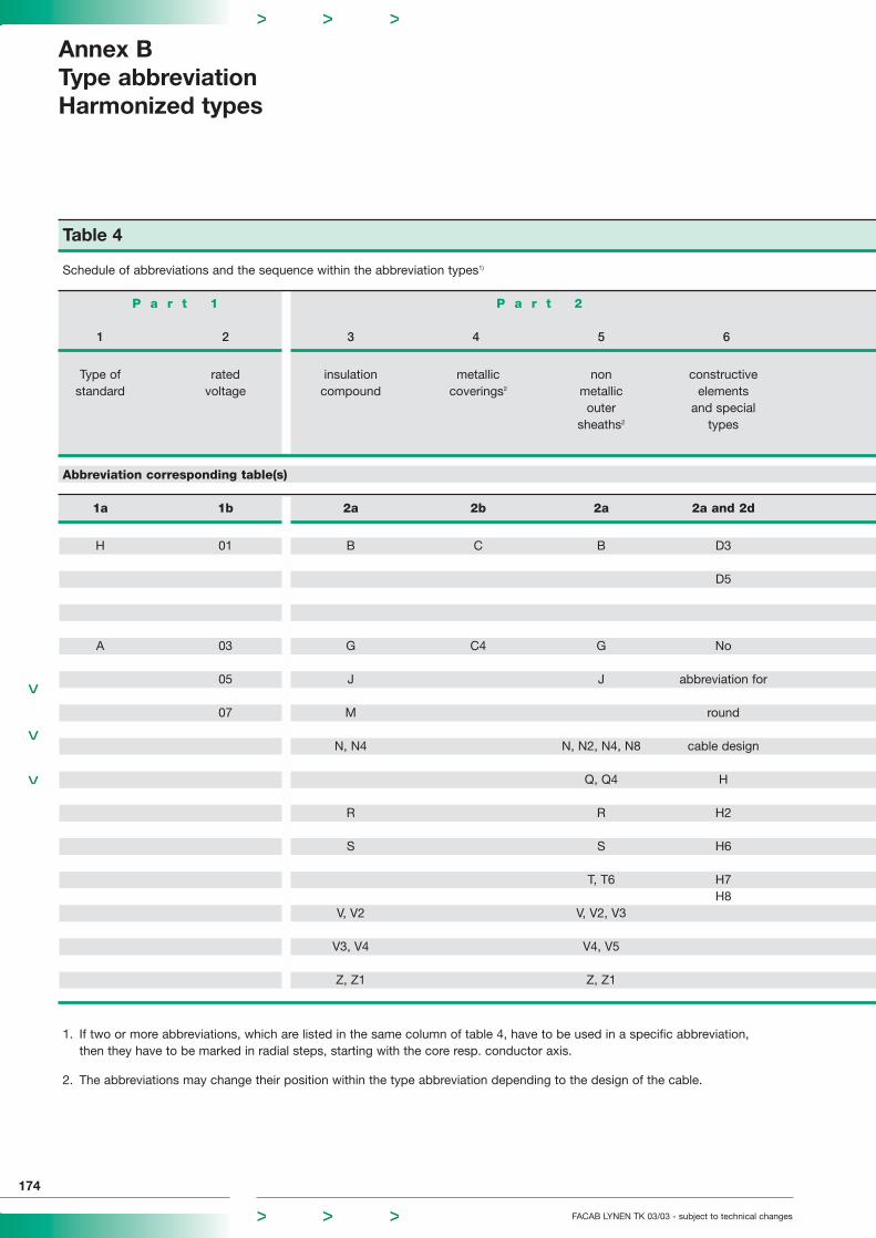
Table 4
Schedule of abbreviations and the sequence within the abbreviation types1)
P a r t 1 P a r t 2
1 2 3 4 5 6
Type of rated insulation metallic non constructivestandard voltage compound coverings2 metallic elements
outer and specialsheaths2 types
Abbreviation corresponding table(s)
1a 1b 2a 2b 2a 2a and 2d
H 01 B C B D3
D5
A 03 G C4 G No
05 J J abbreviation for
07 M round
N, N4 N, N2, N4, N8 cable design
Q, Q4 H
R R H2
S S H6
T, T6 H7H8
V, V2 V, V2, V3
V3, V4 V4, V5
Z, Z1 Z, Z1
1. If two or more abbreviations, which are listed in the same column of table 4, have to be used in a specific abbreviation,then they have to be marked in radial steps, starting with the core resp. conductor axis.
2. The abbreviations may change their position within the type abbreviation depending to the design of the cable.
Annex BType abbreviationHarmonized types
174
FACAB LYNEN TK 03/03 - subject to technical changes

FACAB LYNEN TK 03/03 - subject to technical changes
Annex BType abbreviationHarmonized types
175
P a r t 3
7 8 9 10 11
conductor conductor number sign for conductormaterial shape of multiplication nom. cross section
cores mm2
2e 2f 3
No -D 1 X Y
abbreviation -E 2 0,50
for copper -F 3 G 0,75
-H 4 1
-A -K 5 1
-R and s.o. 2
-U 4
-Y 6
10
16
25
and s.o.

Abbreviation Explanation of the signs Example
1. Types of application
A- outdoor cable A-2YYBYAB- outdoor cable with special construction for lightning protection AB-2YLE2YDB2YAJ- outdoor cable with special construction for protection against interference AJ-2Y(L)2YDBYAJB- outdoor cable with special construction for protection against interference and lightning AJB-2Y(L)2YDBY(A)- outdoor cable deviating from the standard type (A)-9Y(K)2Y4YG- mining cable G-2YY(Z)YGJ- mining cable with special protection against interference GJ-YMBYJ- installation cable J-Y(ST)Y(J)- installation cable deviating from the standard (J)-Y(ST)YJE- cable for industrial electronics JE-Y(ST)Y(JE)- cable for industrial electronics deviating from the standard (JE)-Y(ST)YJ-F flat webbed building wire J-FYL- cables with stranded wires for higher mechanical stresses (multicore cables) L-2YYQYL- FACAB LYNEN-EIB-Bus cable L-Y(ST)YM- measuring cable M-2YC2YRD- control and instrumentation cable RD-Y(ST)YRE- computer cables RE-2Y(ST)2YS- control cable S-Y(ST)YS signal cable A-2YYBY...S(S)- control cable deviating from the standard (S)-Y(ST)YT- distribution cable T-Y(ST)Y
2. Design under the outer sheath: conductor insulation
H halogen-free plastic material J-H(ST)HP paper or air-spaced insulation A-PMBCY polyvinyl chloride PVC J-Y(ST)YYU flame resistant PVC with LOI ≥ 30 RD-YU(ST)YUYW heat resistant PVC up to 90 °C RD-YW(ST)YW2Y solid polyethylene PE A-2Y(L)2Y02Y foamed polyethylene PE A-02Y(L)2Y02YS foamed polyethylene with a solid PE sheath (foam-skin) A-02YS(L)2Y3Y polystyrol (styroflex) S-3Y(ST)Y6Y teflon (FEP) RD-6YC6Y9Y polypropylene (PP) A-9Y(L)2Y09Y foam polypropylene A-09Y(L)2Y09YS foamed polypropylene with a sheath of unfoamed polyolefin A-09YS(L)2Y
Annex BType abbreviationcopper, telecom and data cables
176
FACAB LYNEN TK 03/03 - subject to technical changes
These list contains the most common abbreviations. Single letters have a different meaning, depending on the positionwithin the abbreviations of the cable type, which is described by examples.
Abbreviation Explanation of the signs Example
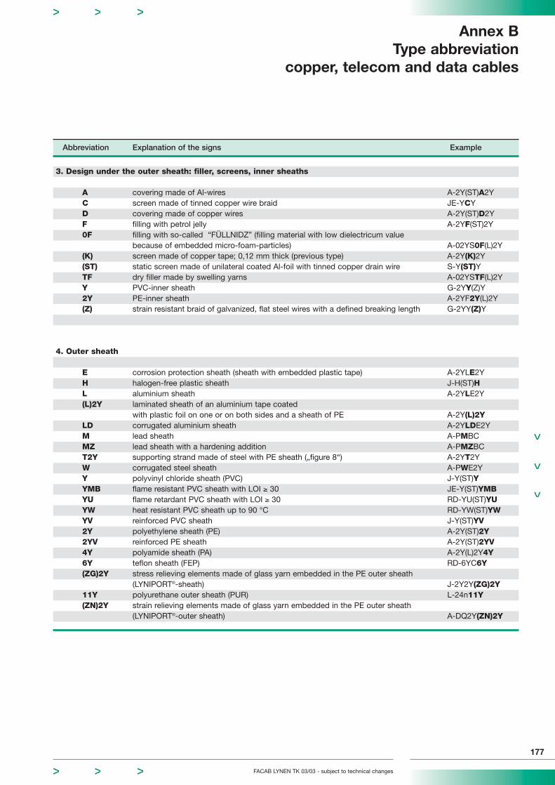
3. Design under the outer sheath: filler, screens, inner sheaths
A covering made of Al-wires A-2Y(ST)A2YC screen made of tinned copper wire braid JE-YCYD covering made of copper wires A-2Y(ST)D2YF filling with petrol jelly A-2YF(ST)2Y0F filling with so-called “FÜLLNIDZ” (filling material with low dielectricum value
because of embedded micro-foam-particles) A-02YS0F(L)2Y(K) screen made of copper tape; 0,12 mm thick (previous type) A-2Y(K)2Y(ST) static screen made of unilateral coated Al-foil with tinned copper drain wire S-Y(ST)YTF dry filler made by swelling yarns A-02YSTF(L)2YY PVC-inner sheath G-2YY(Z)Y2Y PE-inner sheath A-2YF2Y(L)2Y(Z) strain resistant braid of galvanized, flat steel wires with a defined breaking length G-2YY(Z)Y
4. Outer sheath
E corrosion protection sheath (sheath with embedded plastic tape) A-2YLE2YH halogen-free plastic sheath J-H(ST)HL aluminium sheath A-2YLE2Y(L)2Y laminated sheath of an aluminium tape coated
with plastic foil on one or on both sides and a sheath of PE A-2Y(L)2YLD corrugated aluminium sheath A-2YLDE2YM lead sheath A-PMBCMZ lead sheath with a hardening addition A-PMZBCT2Y supporting strand made of steel with PE sheath („figure 8“) A-2YT2YW corrugated steel sheath A-PWE2YY polyvinyl chloride sheath (PVC) J-Y(ST)YYMB flame resistant PVC sheath with LOI ≥ 30 JE-Y(ST)YMBYU flame retardant PVC sheath with LOI ≥ 30 RD-YU(ST)YUYW heat resistant PVC sheath up to 90 °C RD-YW(ST)YWYV reinforced PVC sheath J-Y(ST)YV2Y polyethylene sheath (PE) A-2Y(ST)2Y2YV reinforced PE sheath A-2Y(ST)2YV4Y polyamide sheath (PA) A-2Y(L)2Y4Y6Y teflon sheath (FEP) RD-6YC6Y(ZG)2Y stress relieving elements made of glass yarn embedded in the PE outer sheath
(LYNIPORT®-sheath) J-2Y2Y(ZG)2Y11Y polyurethane outer sheath (PUR) L-24n11Y(ZN)2Y strain relieving elements made of glass yarn embedded in the PE outer sheath
(LYNIPORT®-outer sheath) A-DQ2Y(ZN)2Y
FACAB LYNEN TK 03/03 - subject to technical changes
Annex BType abbreviation
copper, telecom and data cables
177
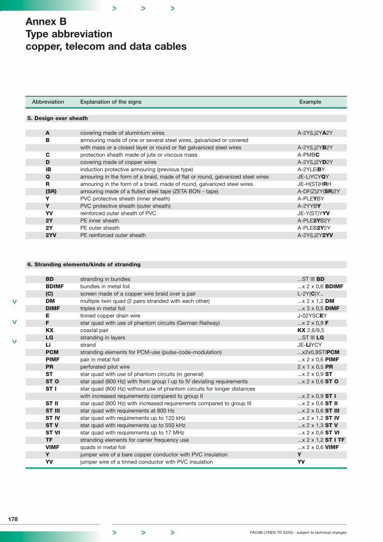
Abbreviation Explanation of the signs Example
5. Design over sheath
A covering made of aluminium wires A-2Y(L)2YA2YB armouring made of one or several steel wires, galvanized or covered
with mass or a closed layer or round or flat galvanized steel wires A-2Y(L)2YB2YC protection sheath made of jute or viscous mass A-PMBCD covering made of copper wires A-2Y(L)2YD2YiB induction protective armouring (previous type) A-2YLEiBYQ amouring in the form of a braid, made of flat or round, galvanized steel wires JE-LiYCYQYR amouring in the form of a braid, made of round, galvanized steel wires JE-H(ST)HRH(SR) amouring made of a fluted steel tape (ZETA BON - tape) A-DF(Z)2Y(SR)2YY PVC protective sheath (inner sheath) A-PLEYBYY PVC protective sheath (outer sheath) A-2YYBYYV reinforced outer sheath of PVC JE-Y(ST)YYV2Y PE inner sheath A-PLE2YB2Y2Y PE outer sheath A-PLEB2Y2Y2YV PE reinforced outer sheath A-2Y(L)2Y2YV
6. Stranding elements/kinds of stranding
BD stranding in bundles ...ST III BDBDIMF bundles in metal foil ...x 2 x 0,6 BDIMF(C) screen made of a copper wire braid over a pair L-2Y(C)Y...DM multiple twin quad (2 pairs stranded with each other) ...x 2 x 1,2 DMDIMF triples in metal foil ...x 3 x 0,5 DIMFE tinned copper drain wire J-02YSCEYF star quad with use of phantom circuits (German Railway) ...x 2 x 0,9 FKX coaxial pair KX 2,6/9,5LG stranding in layers ...ST III LGLi strand JE-LiYCYPCM stranding elements for PCM-use (pulse-code-modulation) ...x2x0,8STIPCMPIMF pair in metal foil ...x 2 x 0,6 PIMFPR perforated pilot wire 2 x 1 x 0,5 PRST star quad with use of phantom circuits (in general) ...x 2 x 0,9 STST O star quad (800 Hz) with from group I up to IV deviating requirements ...x 2 x 0,6 ST OST I star quad (800 Hz) without use of phantom circuits for longer distances
with increased requirements compared to group II ...x 2 x 0,9 ST IST II star quad (800 Hz) with increased requirements compared to group III ...x 2 x 0,6 ST IIST III star quad with requirements at 800 Hz ...x 2 x 0,6 ST IIIST IV star quad with requirements up to 120 kHz ...x 2 x 1,2 ST IVST V star quad with requirements up to 550 kHz ...x 2 x 1,3 ST VST VI star quad with requirements up to 17 MHz ...x 2 x 0,6 ST VITF stranding elements for carrier frequency use ...x 2 x 1,2 ST I TFVIMF quads in metal foil ...x 2 x 0,6 VIMFY jumper wire of a bare copper conductor with PVC insulation YYV jumper wire of a tinned conductor with PVC insulation YV
Annex BType abbreviationcopper, telecom and data cables
178
FACAB LYNEN TK 03/03 - subject to technical changes

Abbreviation Explanation of the signs Example
7. OthersEIB European Installation Bus EIB-BusleitungE30 flame retardant, halogen-free cables with
with a function integrity up to 30 min. to DIN 4102, part 12 (system-test) ...(ST)H FE180/E30E90 as for E30, but up to 90 minutes ...(ST)H FE180/E90
FE180 flame retardant, halogen-free cables withinsulation integrity up to 180 minutes (3hours) to DIN VDE 0472, part 814 ...(ST)H FE180/E30
FRNC flame retardant, non corrosive-JB cables with green-yellow conductor and “coloured”
insulation sheaths to a colour code LiYCY-JB-JZ cables with green-yellow conductor and insulation sheaths with numbers printed on LiYCY-JZKF cold resistant cable (here: up to – 40 °C) L-2YY(Z)YKF40
LSOH Low smoke zero halogeneZHLS Zero halogene low smoke RD-H(ST)HZHLSLOI Limited Oxygen Index (references value for the degree of flame retardancy)TOI Temperature Oxygen Index (references value for the degree of flame retardancy)-OB cables without green-yellow conductor and “coloured”
insulation sheaths to a colour code LiYCY-OB-OZ cables without green-yellow conductor and insulation sheaths with numbers printed on LiYCY-OZSI cables with SIMATIC-colour code JE-Y(ST)Y SIZ bundles with number helix JE-Y(ST)Y Z
-F2 flame resistant cable (bundle test to belgian standard) -F2
TERMI-POINT-Techniqueunsoldered connection technique by means of a special tool where the insulation is stripped off on a metal jamb and is put on electrically conductive with a clip (clamp connection)(TERMI: termination) (Mini-, Standard-, Maxi-Termi-Point)
WIRE-WRAP-Techniqueunsoldered connection technique by means of a special tool where the stripped-off conductoris wrapped closely around a metal bolt. By this procedure an electrically conductive connection is established(Not suitable for stranded conductors)
FACAB LYNEN TK 03/03 - subject to technical changes
Annex BType abbreviation
copper, telecom and data cables
179
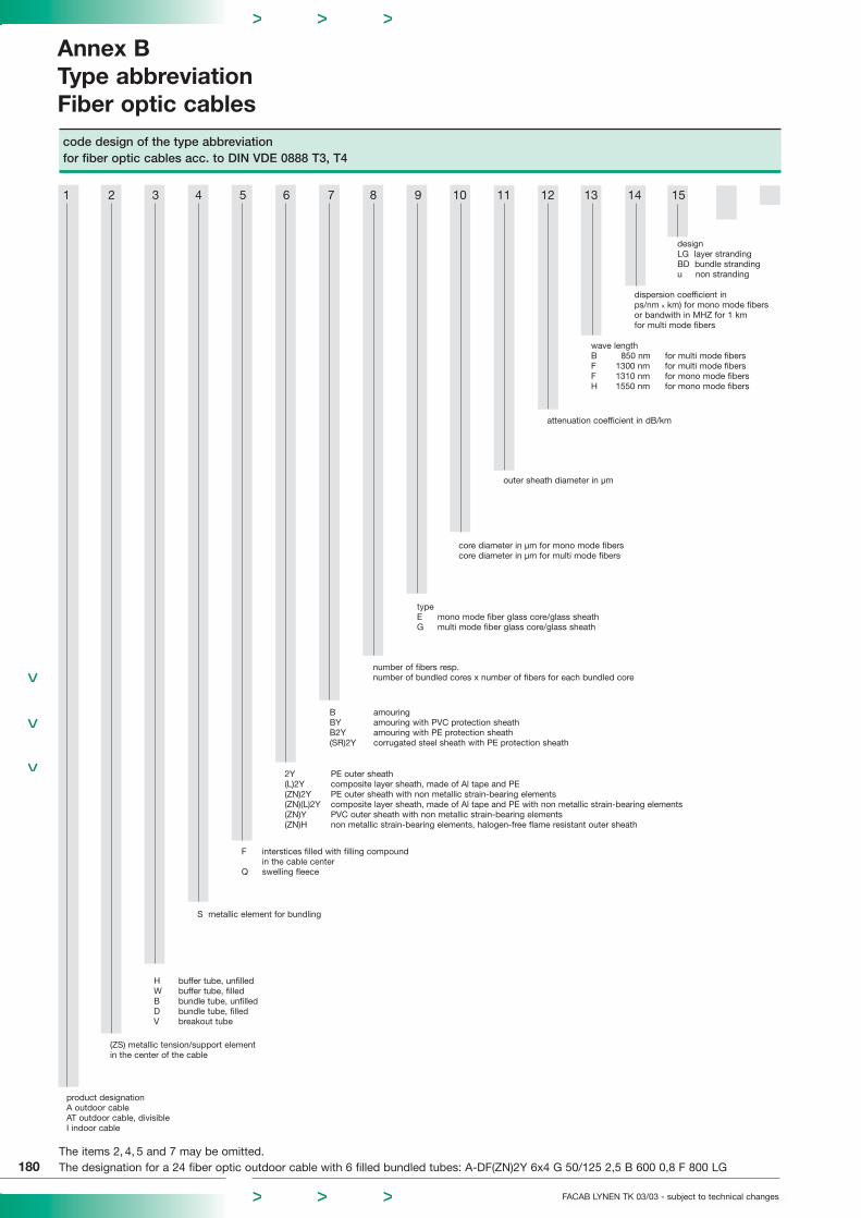
code design of the type abbreviationfor fiber optic cables acc. to DIN VDE 0888 T3, T4
1 2 3 4 5 6 7 8 9 10 11 12 13 14 15
product designationA outdoor cableAT outdoor cable, divisibleI indoor cable
(ZS) metallic tension/support elementin the center of the cable
H buffer tube, unfilledW buffer tube, filledB bundle tube, unfilledD bundle tube, filledV breakout tube
typeE mono mode fiber glass core/glass sheathG multi mode fiber glass core/glass sheath
core diameter in µm for mono mode fiberscore diameter in µm for multi mode fibers
outer sheath diameter in µm
attenuation coefficient in dB/km
F interstices filled with filling compoundin the cable center
Q swelling fleece
2Y PE outer sheath(L)2Y composite layer sheath, made of Al tape and PE(ZN)2Y PE outer sheath with non metallic strain-bearing elements(ZN)(L)2Y composite layer sheath, made of Al tape and PE with non metallic strain-bearing elements(ZN)Y PVC outer sheath with non metallic strain-bearing elements(ZN)H non metallic strain-bearing elements, halogen-free flame resistant outer sheath
B amouringBY amouring with PVC protection sheathB2Y amouring with PE protection sheath(SR)2Y corrugated steel sheath with PE protection sheath
number of fibers resp.number of bundled cores x number of fibers for each bundled core
S metallic element for bundling
wave lengthB 850 nm for multi mode fibersF 1300 nm for multi mode fibersF 1310 nm for mono mode fibersH 1550 nm for mono mode fibers
dispersion coefficient inps/nm x km) for mono mode fibers or bandwith in MHZ for 1 km for multi mode fibers
designLG layer strandingBD bundle strandingu non stranding
The items 2, 4, 5 and 7 may be omitted.The designation for a 24 fiber optic outdoor cable with 6 filled bundled tubes: A-DF(ZN)2Y 6x4 G 50/125 2,5 B 600 0,8 F 800 LG
Annex BType abbreviationFiber optic cables
180
FACAB LYNEN TK 03/03 - subject to technical changes

FACAB LYNEN TK 03/03 - subject to technical changes
Annex BColour coding
Fiber optic cables
181
Colour coding of buffer tubes and bundle tubes
one tube, tracer core redother cores yellow (EM), green (G50), blue (G62,5)dummies any, but not yellow, green and blue
Colours of the fiber cores in a bundle tubefiber-no. colour coding
1 red2 green3 blue4 yellow5 white6 grey7 brown8 violet9 turquoise
10 black11 orange12 pink
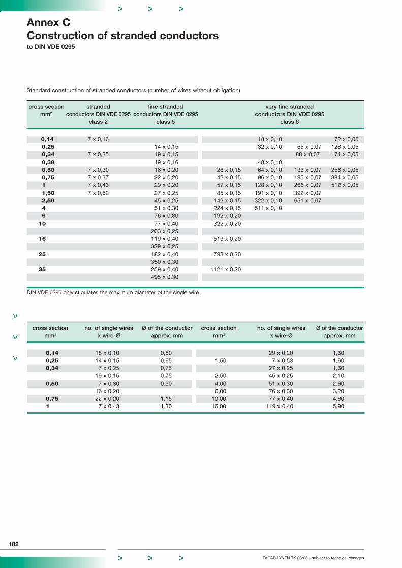
cross section stranded fine stranded very fine strandedmm2 conductors DIN VDE 0295 conductors DIN VDE 0295 conductors DIN VDE 0295
class 2 class 5 class 6
0,14 7 x 0,16 18 x 0,10 72 x 0,05 0,25 14 x 0,15 32 x 0,10 65 x 0,07 128 x 0,050,34 7 x 0,25 19 x 0,15 88 x 0,07 174 x 0,050,38 19 x 0,16 48 x 0,100,50 7 x 0,30 16 x 0,20 28 x 0,15 64 x 0,10 133 x 0,07 256 x 0,050,75 7 x 0,37 22 x 0,20 42 x 0,15 96 x 0,10 195 x 0,07 384 x 0,051 7 x 0,43 29 x 0,20 57 x 0,15 128 x 0,10 266 x 0,07 512 x 0,051,50 7 x 0,52 27 x 0,25 85 x 0,15 191 x 0,10 392 x 0,072,50 45 x 0,25 142 x 0,15 322 x 0,10 651 x 0,074 51 x 0,30 224 x 0,15 511 x 0,106 76 x 0,30 192 x 0,20
10 77 x 0,40 322 x 0,20203 x 0,25
16 119 x 0,40 513 x 0,20329 x 0,25
25 182 x 0,40 798 x 0,20350 x 0,30
35 259 x 0,40 1121 x 0,20495 x 0,30
DIN VDE 0295 only stipulates the maximum diameter of the single wire.
Annex CConstruction of stranded conductors to DIN VDE 0295
182
FACAB LYNEN TK 03/03 - subject to technical changes
Standard construction of stranded conductors (number of wires without obligation)
cross section no. of single wires Ø of the conductor cross section no. of single wires Ø of the conductormm2 x wire-Ø approx. mm mm2 x wire-Ø approx. mm
0,14 18 x 0,10 0,50 29 x 0,20 1,300,25 14 x 0,15 0,65 1,50 7 x 0,53 1,600,34 7 x 0,25 0,75 27 x 0,25 1,60
19 x 0,15 0,75 2,50 45 x 0,25 2,100,50 7 x 0,30 0,90 4,00 51 x 0,30 2,60
16 x 0,20 6,00 76 x 0,30 3,200,75 22 x 0,20 1,15 10,00 77 x 0,40 4,601 7 x 0,43 1,30 16,00 119 x 0,40 5,90

AWG wire-Ø wire cross section conductor resistanceNo. mm mm2 max. Ω/km
44 0,050 0,0019 983041 0,070 0,0038 483040 0,079 0,0050 370039 0,089 0,0063 295038 0,102 0,0078 237037 0,114 0,0095 196036 0,127 0,0123 140135 0,142 0,0153 121034 0,160 0,0201 92533 0,180 0,0254 73032 0,203 0,0314 59131 0,226 0,0415 44330 0,254 0,0510 37129 0,287 0,0660 27828 0,320 0,0804 22927 0,363 0,1018 18126 0,404 0,1257 14625 0,455 0,1590 11424 0,511 0,2043 8423 0,574 0,2642 6722 0,643 0,3217 5421 0,724 0,3959 4320 0,813 0,5153 3419 0,912 0,6504 2718 1,024 0,8171 2117 1,151 1,0387 16,916 1,290 1,3070 13,515 1,450 1,6513 10,614 1,628 2,0867 8,513 1,829 2,6270 7,312 2,052 3,3080 5,7511 2,304 4,1680 4,5410 2,588 5,2620 3,599 2,906 6,3200 2,998 3,268 8,3870 2,257 3,665 10,5510 1,796 4,115 13,2890 1,425 4,620 16,7660 1,124 5,189 21,1490 0,893 5,827 26,6850 0,702 6,543 33,6240 0,561 7,348 42,4090 0,44
FACAB LYNEN TK 03/03 - subject to technical changes
Annex CConstruction of wires and stranded conductors
to DIN VDE 0295
183
AWG-Std. cross section solid wire construction of stranded conductor, metric construction of stranded mm2 Ø mm no. of wires x wires-Ø conductor to AWG standard
standard flexible standard flexible
28 0,09 0,320 7 x 0,13 19 x 0,08 7/36 19/4026 0,15 0,404 7 x 0,16 19 x 0,10 7/34 19/3824 0,22 0,511 7 x 0,20 19 x 0,13 7/32 19/3622 0,34 0,643 7 x 0,25 19 x 0,16 7/30 19/3420 0,56 0,813 7 x 0,32 19 x 0,20 7/28 19/3218 0,96 1,024 7 x 0,40 19 x 0,25 7/26 19/3016 1,42 1,300 7 x 0,51 19 x 0,32 7/24 19/2814 2,25 1,620 7 x 0,64 19 x 0,40 7/22 19/26
Conversion table of AWG wires
Stranded conductors of AWG 28-14
* AWG = American Wire Gauge
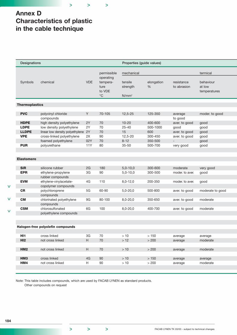
Designations Properties (guide values)
permissible mechanical termicaloperating
Symbols chemical VDE tempera- tensile elongation resistance behaviourture strength % to abrasion at lowto VDE temperatures°C N/mm2
Thermoplastics
PVC polyvinyl chloride Y 70-105 12,5-25 125-350 average moder. to goodcompounds to good
HDPE high density polyethylene 2Y 70 10-20 400-600 aver. to good goodLDPE low density polyethylene 2Y 70 25-40 500-1000 good goodLLDPE linear low density polyethylene 2Y 70 15 600 aver. to good good VPE cross-linked polyethylene 2X 90 12,5-20 300-450 aver. to good good
foamed polyethylene 02Y 70 8-12 350-500 - goodPUR polyurethane 11Y 80 35-50 500-700 very good good
Elastomere
SiR silicone rubber 2G 180 5,0-10,0 300-600 moderate very goodEPR ethylene-propylene 3G 90 5,0-10,0 300-500 moder. to aver. good
rubber compoundsEVM ethylene-vinylacetate- 4G 110 8,0-12,0 200-350 moder. to aver. good
copolymer compoundsCR polychloroprene 5G 60-90 5,0-20,0 500-800 aver. to good moderate to good
compoundsCM chlorinated polyethylene 9G 80-100 8,0-20,0 350-650 aver. to good moderate
compoundsCSM chlorosulfonated 6G 100 8,0-20,0 400-700 aver. to good moderate
polyethylene compounds
Halogen-free polyolefin compounds
HI1 cross linked 3G 70 > 10 > 150 average averageHI2 not cross linked H 70 > 12 > 200 average moderate
HM2 not cross linked H 70 > 10 > 200 average moderate
HM3 cross linked 4G 90 > 10 > 150 average averageHM4 not cross linked H 90 > 10 > 200 average moderate
Note: This table includes compounds, which are used by FACAB LYNEN as standard products.Other compounds on request
Annex DCharacteristics of plasticin the cable technique
184
FACAB LYNEN TK 03/03 - subject to technical changes
FACAB LYNEN TK 03/03 - subject to technical changes
Annex DCharacteristics of plastic
in the cable technique
185
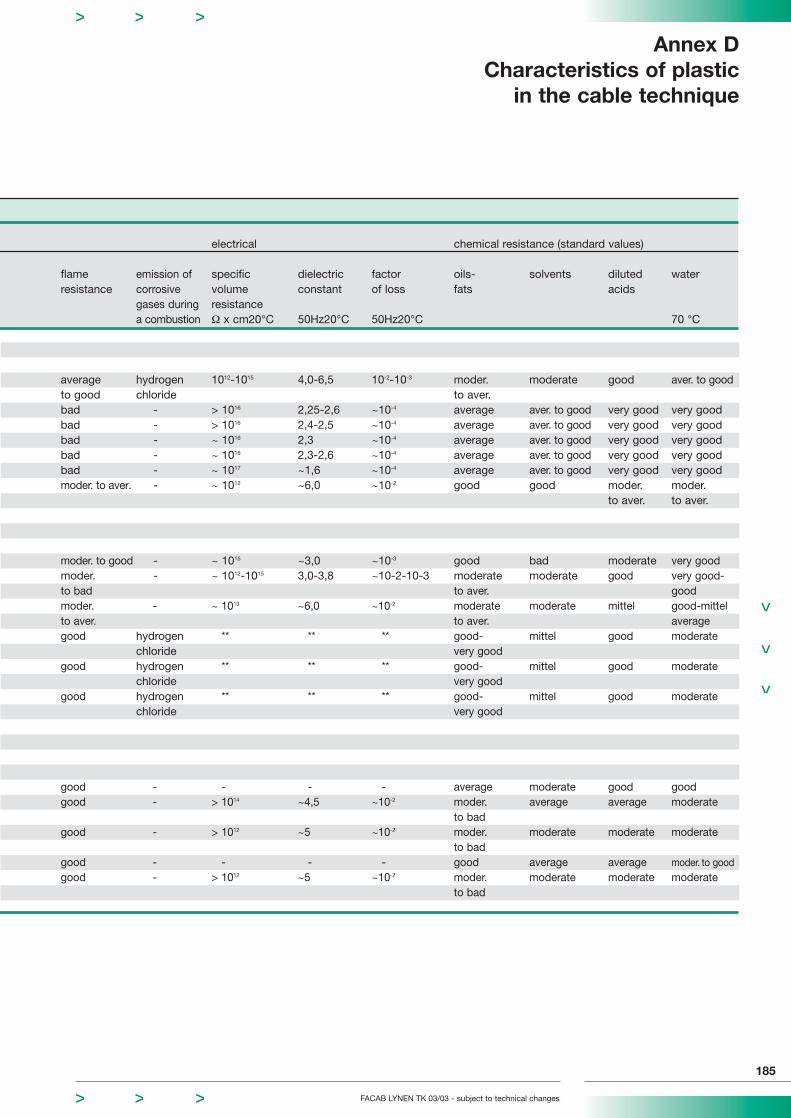
electrical chemical resistance (standard values)
flame emission of specific dielectric factor oils- solvents diluted waterresistance corrosive volume constant of loss fats acids
gases during resistancea combustion Ω x cm20°C 50Hz20°C 50Hz20°C 70 °C
average hydrogen 1012-1015 4,0-6,5 10-2-10-3 moder. moderate good aver. to goodto good chloride to aver.bad - > 1016 2,25-2,6 ~10-4 average aver. to good very good very goodbad - > 1016 2,4-2,5 ~10-4 average aver. to good very good very goodbad - ~ 1016 2,3 ~10-4 average aver. to good very good very goodbad - ~ 1016 2,3-2,6 ~10-4 average aver. to good very good very goodbad - ~ 1017 ~1,6 ~10-4 average aver. to good very good very goodmoder. to aver. - ~ 1012 ~6,0 ~10-2 good good moder. moder.
to aver. to aver.
moder. to good - ~ 1015 ~3,0 ~10-3 good bad moderate very goodmoder. - ~ 1012-1015 3,0-3,8 ~10-2-10-3 moderate moderate good very good-to bad to aver. goodmoder. - ~ 1013 ~6,0 ~10-2 moderate moderate mittel good-mittelto aver. to aver. averagegood hydrogen ** ** ** good- mittel good moderate
chloride very goodgood hydrogen ** ** ** good- mittel good moderate
chloride very goodgood hydrogen ** ** ** good- mittel good moderate
chloride very good
good - - - - average moderate good goodgood - > 1014 ~4,5 ~10-2 moder. average average moderate
to badgood - > 1012 ~5 ~10-2 moder. moderate moderate moderate
to badgood - - - - good average average moder. to goodgood - > 1012 ~5 ~10-2 moder. moderate moderate moderate
to bad
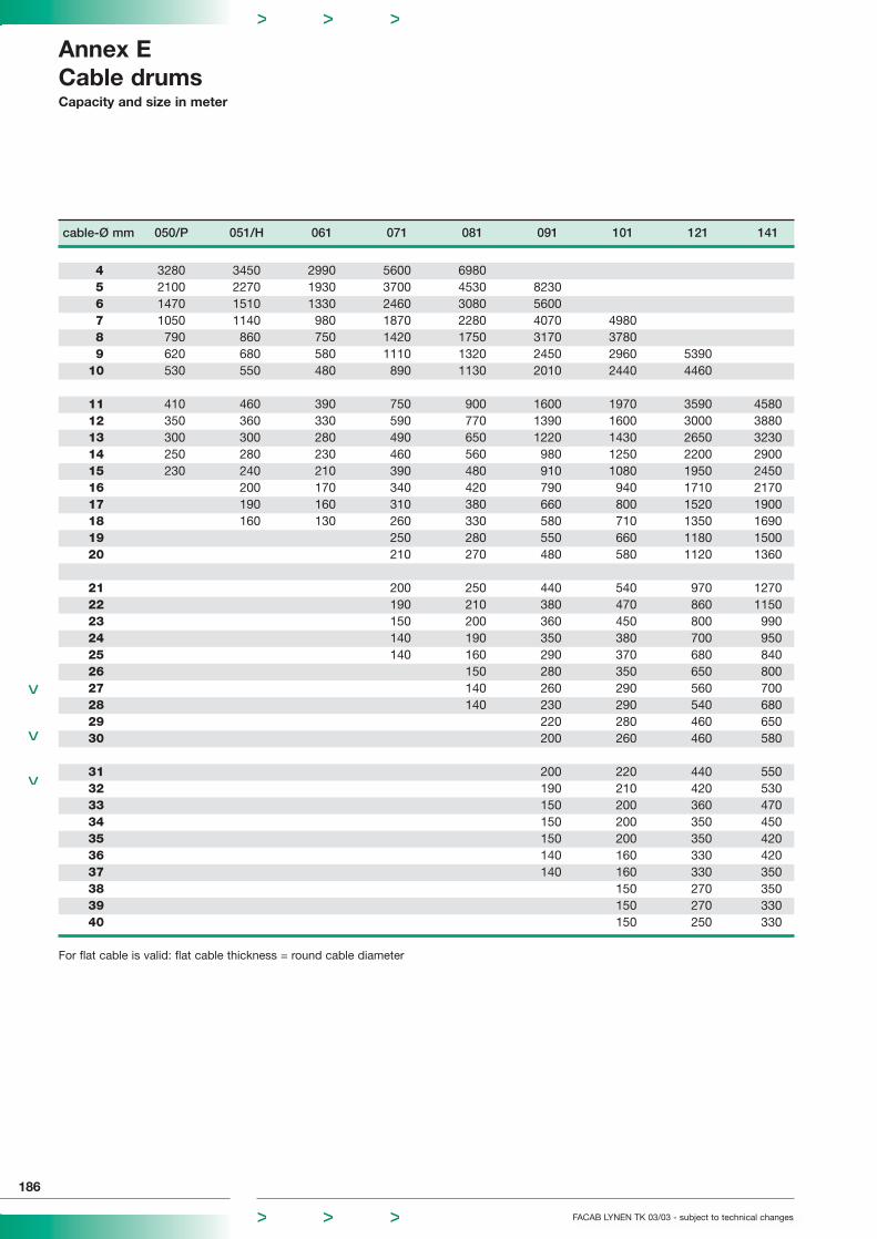
cable-Ø mm 050/P 051/H 061 071 081 091 101 121 141
4 3280 3450 2990 5600 69805 2100 2270 1930 3700 4530 82306 1470 1510 1330 2460 3080 56007 1050 1140 980 1870 2280 4070 49808 790 860 750 1420 1750 3170 37809 620 680 580 1110 1320 2450 2960 5390
10 530 550 480 890 1130 2010 2440 4460
11 410 460 390 750 900 1600 1970 3590 458012 350 360 330 590 770 1390 1600 3000 388013 300 300 280 490 650 1220 1430 2650 323014 250 280 230 460 560 980 1250 2200 290015 230 240 210 390 480 910 1080 1950 245016 200 170 340 420 790 940 1710 217017 190 160 310 380 660 800 1520 190018 160 130 260 330 580 710 1350 169019 250 280 550 660 1180 150020 210 270 480 580 1120 1360
21 200 250 440 540 970 127022 190 210 380 470 860 115023 150 200 360 450 800 99024 140 190 350 380 700 95025 140 160 290 370 680 84026 150 280 350 650 80027 140 260 290 560 70028 140 230 290 540 68029 220 280 460 65030 200 260 460 580
31 200 220 440 55032 190 210 420 53033 150 200 360 47034 150 200 350 45035 150 200 350 42036 140 160 330 42037 140 160 330 35038 150 270 35039 150 270 33040 150 250 330
For flat cable is valid: flat cable thickness = round cable diameter
Annex ECable drumsCapacity and size in meter
186
FACAB LYNEN TK 03/03 - subject to technical changes
FACAB LYNEN TK 03/03 - subject to technical changes
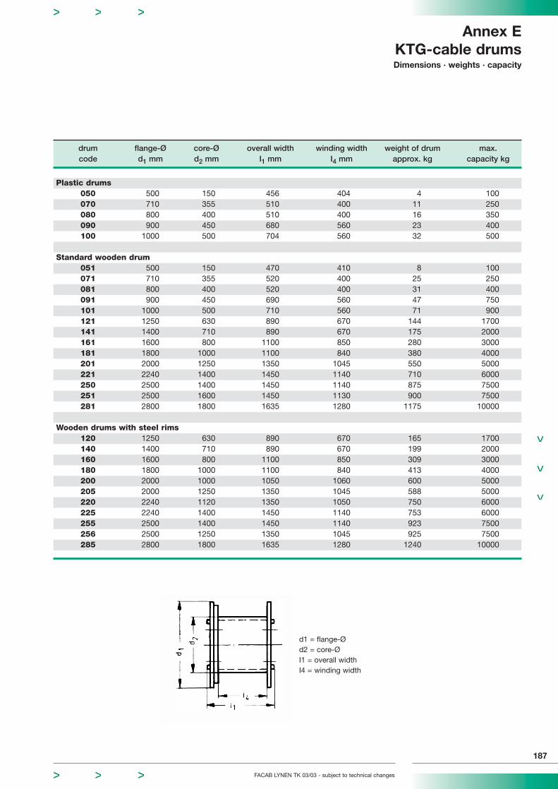
Annex EKTG-cable drumsDimensions · weights · capacity
187
drum flange-Ø core-Ø overall width winding width weight of drum max.code d1 mm d2 mm I1 mm I4 mm approx. kg capacity kg
Plastic drums050 500 150 456 404 4 100070 710 355 510 400 11 250080 800 400 510 400 16 350090 900 450 680 560 23 400100 1000 500 704 560 32 500
Standard wooden drum051 500 150 470 410 8 100071 710 355 520 400 25 250081 800 400 520 400 31 400091 900 450 690 560 47 750101 1000 500 710 560 71 900121 1250 630 890 670 144 1700141 1400 710 890 670 175 2000161 1600 800 1100 850 280 3000181 1800 1000 1100 840 380 4000201 2000 1250 1350 1045 550 5000221 2240 1400 1450 1140 710 6000250 2500 1400 1450 1140 875 7500251 2500 1600 1450 1130 900 7500281 2800 1800 1635 1280 1175 10000
Wooden drums with steel rims120 1250 630 890 670 165 1700140 1400 710 890 670 199 2000160 1600 800 1100 850 309 3000180 1800 1000 1100 840 413 4000200 2000 1000 1050 1060 600 5000205 2000 1250 1350 1045 588 5000220 2240 1120 1350 1050 750 6000225 2240 1400 1450 1140 753 6000255 2500 1400 1450 1140 923 7500256 2500 1250 1350 1045 925 7500285 2800 1800 1635 1280 1240 10000
d1 = flange-Ød2 = core-ØI1 = overall widthI4 = winding width

General terms of delivery and trade
188
FACAB LYNEN TK 03/03 - subject to technical changes
All – including future – deliveries and services shall be solely provided on the basis of thefollowing conditions. The purchasers terms of delivery and trade are herewith contradicted.They shall also not be recognised, if they are not explicitly contradicted again followingreceipt by the vendor. The terms of sale are deemed as having been accepted on receiptof the goods at the latest. Deviating terms arising out of subsidiary agreements must beconfirmed in writing.
1. Offer, order confirmationOur offers and quotations are subject to change and are not binding for repeat orders.If cost increases arise, we explicitly reserve the right to make a reasonable adjustmentto the prices. The price calculations in our order confirmation are based on the respec-tive price lists, whereby the metal prices are calculated in accordance with item 3.These are determined by the metal prices of the workday following receipt of the clarified order. Delivery costs shall be added. The purchaser does not have a right todelivery until the order has been clarified. The order is deemed to be clarified as soonas all items have been mutually agreed, including the delivery date. The prices do notinclude VAT.
2. PricingThe prices apply in accordance with INCOTERMS 2000:EXW ex worksFOB free on boardCIF cost, insurance and freightThe buyer shall be charged with all additional costs incurred due to special dispatchregulations and dispatch by post. Supplements for goods sent by express deliveryshall be charged separately. Any collection shall be charged to the buyer.
3. Metal Prices and CalculationThe following are decisive for determining the metal price calculations:For copper: The quoted price for electrolytic copper, as published in the businessnewspapers under the heading “non-ferrous metal processor prices“ (Del-Notiz), plusdelivery costs. If the Del-Notiz deviates from the basis of the standard price, the pricesfor each 1000 m length shall be increased or reduced by the amount resulting fromthe multiplication of the given copper number with the copper difference.Supplementary charges or price reductions for copper are always net prices.For aluminium: The quoted price of the non-ferrous metal processors of aluminiumfor conducting purposes, as published in the business newspapers. The additionalcharge or reduced price results from the multiplication of the aluminium number withthe aluminium price. Supplementary charges or price reductions for copper are alwaysnet prices.For lead: The quoted price of the non-ferrous metal processors of lead in cables toDIN 17 640, as published in the business newspapers. If this deviates from the basisof the standard price, the prices for each 1000 m length shall be increased or reducedby the amount resulting from the multiplication of the given lead number with the leadprice difference. Supplementary charges or price reductions for copper are always netprices.
4. PaymentAll invoices are payable as follows, where no alternative arrangements have been made:4.1. 3% discount for payments received within 10 days. 2% discount for payments re-
ceived within 30 days or on the 15th of the month following delivery or net on receiptof payment within 60 following the invoice date or after reporting that the goods areready for dispatch.
4.2. The payment deadlines are calculated from the date the invoice is issued. 4.3. We are unable to grant discount until all other accounts payable and due have been
settled. Invoices on account are payable immediately without any deduction.4.4. In special cases, we reserve the right to demand advance or immediate payment. For all
payments, the day of payment is the day on which we can dispose of the sum. The pay-ments must be made exclude any right to setoff and retention. By prior agreement,checks and bills of exchange can also be accepted in lieu of payment. Discount chargesand interest must be reimbursed.
4.5. If the buyer fails to comply with our payment terms, all accounts receivable – withoutregard for any bills of exchange received – shall be due immediately and the buyer shallbe in default without requiring a special reminder. The whole of the supplier’s accountreceivable shall also be due immediately in the case of suspension of payments, requestfor composition or moratorium. Commercial interests of delay shall be charged subjectto the reservation of the right to claim other rights.
4.6. If metals (copper, aluminium, lead) are bought ahead at the request of a buyer, without aspecific order being placed, we shall invoice the buyer for the metals. The metal invoiceis due for immediate payment and without any deductions. After the payment has beenreceived the metal becomes the unsaleable property of the buyer.
4.7. If metals are consigned, these must be made available on the date of the order, however by 8 weeks before the agreed date at the latest.
5. Proprietary reservation All delivered goods remain our property (proviso goods) until all our demands have beenfulfilled, including accounts receivable due in the future, for whatever legal reason, especially our respective balance accounts receivable, even if payments have been madefor specially denoted demands. The purchaser may process and sell the goods under theirnormal terms and conditions of trade and under consideration of the following terms andconditions. 5.1. The authority of the purchaser to sell, process, mix and combine the conditional
property in proper business transactions ends, not withstanding any retraction by thevendor permitted at any time, as long as they are not in delay with any debts, however with the cancellation of the purchaser’s payments at the latest or if applica-tion is made for the opening of bankruptcy proceedings or judicial or non-judicial proceedings with respect to the purchaser’s assets or the vendor seeks a moratorium.
5.2. Pledging or transfer of ownership of the proviso goods resp. the transfered debts isnot permitted.
5.3. The purchaser does not acquire ownership of the new object in accordance with § 950 BGB (German Civil Code) by processing the proviso goods. The processing isdeemed to have been carried out by the purchaser on behalf of the vendor. If the proviso goods are processed with other goods belonging to the purchaser or purchased under simple proprietary reservation in accordance with § 455 BGB, thevendor acquires sole ownership of the processed product. If the proviso goods is processed with other supplied goods, also under extended reservation of proprietaryrights, i.e. with exclusion of the legal consequences of § 950 BGB, the vendor acquires co-ownership of the new goods based on the invoiced value of their provisogoods compared with the invoiced value of the other processed goods.
5.4. The purchaser herewith assigns to the vendor all accounts receivable from further saleof the proviso goods and including where the goods have been processed. If, apartfrom the proviso goods of the vendor, the processed product only contains suchobjects, which did not belong to the purchaser, and nor were they delivered by simpleproprietary reservation rights in accordance with § 455 BGB, the purchaser assigns tothe vendor the whole sum due with respect to the purchase price. In the other case,i.e. in the case of concurrence of advanced assignments to several suppliers, the vendor shall be entitled to the respective fraction of the sum due from the purchaseprice according to an arrangement as provided for under Item 5.3.
5.5. Rights arising out of the proprietary reservation and all the special forms stipulated in these terms and conditions apply until complete release from the ownershipobligations, which the vendor has entered into in the interest of the purchaser.
5.6. The purchaser is entitled to collect accounts receivable from the sale until cancellationby the vendor, which can be issued at any time. The vendor shall only make use oftheir right to cancel in the cases named under items 1 to 10. At the request of the vendor the purchaser is obliged to inform immediately their buyer of the assignmentto the vendor – where the vendor does not do this themselves – and to give the vendor the information and documents required to collect the payments.
5.7. If the guaranty provided by the proprietary reservation exceeds the accounts receivable to be secured by 20 %, the vendor shall release fully paid deliveries at theirown choice.
5.8. a) Failure to comply with the payment terms or circumstances, which the vendor becomes aware of following the respective conclusion of a contract, and which in thevendor’s opinion are suitable for reducing the trustworthiness of the purchaser, shallresult in all the vendor’s accounts receivable becoming due without consideration ofthe term of any bills of credit received and credited. Furthermore, in such a case thevendor is entitled not to carry out any outstanding deliveries unless paid for in advanceor in exchange for collateral and to withdraw from the contract following a reasonablegrace period or to compensation due to non-performance.
5.8. b) The vendor can also refuse the resale and processing of the goods delivered subject to proprietary preservation and demand their return or transfer of indirectownership at the cost of the purchaser and cancel the purchaser’s right to collect payments. In these named cases, the purchaser agrees herewith to the taking awayof the delivered goods by the vendor. The purchaser obligates himself to send the vendor a list of the still available goods with reserved proprietary rights, even wherethese have been processed, and a list of the accounts receivable from third party debtors, including copies of the invoices, as soon as they cancel their payments, andimmediately following notification of the payment cancellation. Sums received by the purchaser for the for assigned accounts receivable are to be kept separately untiltransfered.
5.8. c) The vendor is free to choose the way in which they use these objects, they are notobliged to keep to the provisions of the BGB concerning compulsory disposal.
6. Buyer’s Obligation to Surrender If the buyer come in default according to these terms and conditions of sale, we shallbe entitled to demand immediate surrender of the goods with reserved proprietary titleas soon as the purchaser is in default, and may demand surrender without noticeof the owned proviso goods as well as a compensation of the interest of fulfilment fordamages caused by default.

FACAB LYNEN TK 03/03 - subject to technical changes
189
7. Packaging7.1. Cable drums on hire: The goods shall be delivered on drums provided by the firm
Kabeltrommel GmbH & Co. KG. Cologne, and to their terms.
8. Under resp. Over Delivery The manufacturer has the right to supply the ordered quantities with up to 10 % underdelivery resp. up to 5% over delivery for short lengths of. The proportion of shortlengths must not exceed 10 % of the ordered quantity.
9. Terms of Delivery The terms of delivery given in the offer is subject to being sold. The terms of deliveryagreed in the order confirmation run from the day of the full clarification of the order.All provisos arising from unforeseen hindrances, both in our own company as well asthose that may result for our suppliers apply for the terms of delivery. The acceptanceand execution of orders shall take place subject to the possibility of procuring thenecessary raw materials. The notification of readiness to dispatch (i.e. readiness toload) shall be deemed the same as to delivery.
10. Passing of RiskAll risks pass to the buyer when the dispatch (goods and packaging) leave the company or are reported ready for dispatch or collection, even if the dispatch locationis not the place of performance, if no other terms of delivery are arranged ( for exampleFOB).
11. WarrantyThe supplier’s products are state of the art and comply with the relevant technical standards. The buyer can only make claims due to an obvious defect in the goods within two weeks. In addition, we grant a warranty for the case of immediately reporteduselessness of the goods as a result of proven material defects or manufacturingdefects.For cables, bare conductor material and fittings 3 years following commissioning ordelivery, however such that we shall improve or replace the damaged piece of cable.Other claims are precluded especially for compensation for consequential damages.We can refuse to give a guarantee in the case of delayed payment and withdrawal ofcredit. Replaced goods become our property. Defects in cables can only be com-plained of on the basis of cable testing, if they are tested before being installed andwithin one month of delivery. Tension tests are to be carried out on random samples;the cable is deemed in good order if 2/3 of the random samples have adequate values.
12. Applications Technology AdviceOur advice, e.g. in the form of publication, information and details concerning the data,suitability and use of our products, is established by means of measurements, labora-tory investigations or processing trials carried out to the best of our knowledge to stateof the art technological standards. However, it is non-binding and does not release thepurchaser from their duty to test these products themselves with respect to their suitability for the intended processes and purposes. This also applies for the respectiveproprietary rights. Advice or a recommendation provided by us shall not justify anycontractual legal relationship, or a subsidiary obligation to the purchase agreement, sothat we are not liable for such activity. Nevertheless, should liability casting doubtsupon, this shall be limited to the same extent as justified defects complaints. If the purchaser is issued analyses data or product specifications supplied by them arechecked, such notifications or details of the results of the checks shall not representassured product properties. Instead, the above paragraph shall apply accordingly.
13. Third Party Proprietary RightsThe buyer bears all the risks, if third parties are injured in the case of delivery to drawings or other details provided by the buyer.
14. Dimensional and Weight InformationAll information concerning the diameters and weights of the products is non-bindingand structural & dimensional deviations are deemed approximate. We reserve theright to make structural & dimensional product changes due to fabrication or rawmaterial reasons.
15. ReturnsReturns shall only be accepted by written mutual arrangement.
16. Call Off OrdersIn the case of call off orders, the buyer obligates that the deadline for the deliveries iswithin max.12 months and the goods are delivered complete. If no other explicit arrange-ments are made, calls must be made within 6 months. If the call-up deadline is notcomplied, the supplier has the right to insist on payment and acceptance.
17. Place of Performance and VenueEschweiler, where permitted by law.
18. ValiditySo far as the above terms and conditions do not make provision for alternative arrangements or should any of the individual terms and conditions given above beinvalid, the respective latest version of the general terms and conditions of delivery forElectrical Industry shall apply. The buyer’s deviating delivery terms are explicitly precluded.
Issued: January 2003