accessories selection guide for impedance measurements
TRANSCRIPT

Accessories Selection GuideFor Impedance Measurements
April 2005

Table of Contents
Introduction 11. What are Agilent Accessories? 12. Types of Accessories 13. The Benefits of Agilent Accessories 24. ISO 9000 Quality Management 2
Tips for Selecting Appropriate Accessories 31. Selection by Measurement Application 32. Compatibility with Measurement Instruments 33. Frequency, DC Bias, and Operating Temperature/Humidity 44. DUT (Device Under Test) Dimensions 45. Open & short Repeatability and Proportional Error 46. Furnished Accessories 47. Terminal Adapters 5
Accessory CatalogueApplicable Frequency Ranges 6Accessories Organization 7
Up to 110 MHz (4-Terminal Pair) 9Lead Components:
16047A Test Fixture 1016047D Test Fixture 1116047E Test Fixture 1216060A Transformer Test Fixture 13
SMD:16034E Test Fixture 1416034G Test Fixture 1516034H Test Fixture 1616044A Test Fixture 17-1816334A Tweezers Contact Test Fixture 1916043A/B 3-Terminal SMD Test Fixture 20-22
Other Components (Varying in Size or Shape):16089A Large Kelvin Clip Leads 2316089B Medium Kelvin Clip Leads 2316089C Kelvin IC Clip Leads 2416089D Kelvin Alligator Clip Leads 2416089E Kelvin Clip Leads 25
Port/Cable Extension:16048A Test Leads 2616048B Test Leads 2616048D Test Leads 2716048E Test Leads 2716048G Test Leads 2816048H Test Leads 28

Balanced/Unbalanced Converters:16314A Balanced/Unbalanced 4-Terminal Converter 29
Probes:16095A Probe Test Fixture 3042941A Impedance Probe Kit 31
DC Bias Accessories:16065A 200 Vdc External Voltage Bias Fixture 3216065C 40 Vdc External Voltage Bias Adapter 3242841A Bias Current Source 3342842A Bias Current Test Fixture 3442842B Bias Current Test Fixture 3542842C Bias Current Test Fixture 36P/N 42851-61100 3642843A Bias Current Cable 37
Material:16451B Dielectric Test Fixture 38-4116452A Liquid Dielectric Test Fixture 42-43
Up to 3 GHz (7 mm) 45Lead Components:
16092A Spring Clip Test Fixture 4616093A Binding Post Test Fixture 4716093B Binding Post Test Fixture 48
SMD:16191A Side Electrode SMD Test Fixture 49-5016192A Parallel Electrode SMD Test Fixture 51-5216194A High Temperature Component Test Fixture 53-5416196A Parallel Electrode SMD Test Fixture 55-5716196B Parallel Electrode SMD Test Fixture 58-5916196C Parallel Electrode SMD Test Fixture 60-6116196D Parallel Electrode SMD Test Fixture 62-6316197A Bottom Electrode SMD Test Fixture 64-66
Probes:16094A Probe Test Fixture 67
DC Bias Accessories:16200B External DC Bias Adapter 68
Material:16453A Dielectric Material Test Fixture 6916454A Magnetic Material Test Fixture 70-71
DC (High Resistance) 73SMD & Lead Components:
16339A Component Test Fixture 74SMD:
16118A Tweezers Test Fixture 75

Other Components (Varying in Size, Shape or Grounded):16117B Low Noise Test Leads 7616117C Low Noise Test Leads 7716117E Low Noise Test Leads 77
Material:16008B Resistivity Cell 78-79
1 kHz (Milliohm) 81Various Components:
16338A Test Lead Kit 8216143B Mating Cable 8316005B Kelvin Clip Leads 8316005C/D Kelvin IC Clip Leads 8316006A Pin-type Leads 8416007A/B Kelvin Alligator Clip Leads 84
Other Accessories16064B LED Display/Trigger Box 8516190B Performance Test Kit 8616380A Standard Capacitor Set 8716380C Standard Capacitor Set 8842030A Four-Terminal Pair Standard Resistor Set 8942090A Open Termination 9042091A Short Termination 90
AppendixThe Concept of a Test Fixture’s Additional Error 91
1. System Configuration for Impedance Measurement 912. Measurement System Accuracy 91-933. New Market Trends and the Additional Error for Test Fixtures 93-95
Error Compensation 961. Open/short Compensation 962. Open/short/load Compensation 963. Electrical Length Compensation 974. Cable Length Compensation 98
Measurement Repeatability 98Index 99-101
Test Fixture Selection By SMD Size 102Accessories vs. Instruments Matrix 103

This page intentionally left blank.

When a device under test (DUT) is measured, a test fixture must be used to connect the instrument tothe DUT. A test fixture is an interface specifically designed to connect the instrument and the contacttips of the DUT.
1. What are Agilent Accessories?Agilent offers a variety of accessories suitable for many applications. They are designed to make mea-surements simple and reliable. For example, a mechanically and electrically precise test fixture isrequired to measure the impedance of SMD components. For this measurement, Agilent offers dedicatedSMD fixtures for impedance measurement instruments that minimize the measurement errors. Also,specially designed fixtures for other specific applications (such as DC bias test, dielectric material test,and others.) are available. Agilent accessories facilitate a shorter time-to-market with increased confi-dence by providing accurate and repeatable measurements.
2. Types of Accessories
Agilent accessories can be divided into the following five categories:
Test FixturesA test fixture is used to hold the electronic components or materials (physically and electrically) for themeasurements. Agilent offers various kinds of 4-Terminal Pair test fixtures and 7 mm test fixtures.Some of them connect directly to the measurement instrument, while others require adapters.
Test LeadsTest leads are used to extend the measurement ports from the UNKNOWN terminals of the instrumentto the DUT. Using a flexible test lead, a DUT that cannot be held with test fixtures can be measuredregardless of its size or shape. The test leads can also be used as cable extensions when the test sampleis located away from the measurement instrument.
ProbesProbes are helpful in measuring components which are already connected to PC boards or have one ter-minal grounded. The probes shown in this selection guide have a wide frequency range and are simple touse.
AdaptersAdapters are used to adapt the dedicated circuits between the instrument and the test fixtures. The16085B is a terminal conversion adapter that can convert a 4-Terminal Pair configuration to a 7 mmconfiguration. The 16065C is an external DC bias adapter that can apply DC bias to the DUT from anexternal DC bias source.
OthersAlso available are DC bias accessories and performance test equipment.
Introduction
1
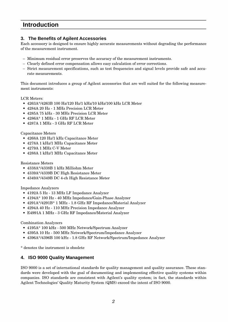
3. The Benefits of Agilent AccessoriesEach accessory is designed to ensure highly accurate measurements without degrading the performanceof the measurement instrument.
– Minimum residual error preserves the accuracy of the measurement instruments. – Clearly defined error compensation allows easy calculation of error corrections.– Strict measurement specifications, such as test frequencies and signal levels provide safe and accu-
rate measurements.
This document introduces a group of Agilent accessories that are well suited for the following measure-ment instruments:
LCR Meters:• 4263A*/4263B 100 Hz/120 Hz/1 kHz/10 kHz/100 kHz LCR Meter• 4284A 20 Hz - 1 MHz Precision LCR Meter• 4285A 75 kHz - 30 MHz Precision LCR Meter• 4286A* 1 MHz - 1 GHz RF LCR Meter • 4287A 1 MHz - 3 GHz RF LCR Meter
Capacitance Meters• 4268A 120 Hz/1 kHz Capacitance Meter• 4278A 1 kHz/1 MHz Capacitance Meter• 4279A 1 MHz C-V Meter• 4288A 1 kHz/1 MHz Capacitance Meter
Resistance Meters• 4338A*/4338B 1 kHz Milliohm Meter• 4339A*/4339B DC High Resistance Meter• 4349A*/4349B DC 4-ch High Resistance Meter
Impedance Analyzers• 4192A 5 Hz - 13 MHz LF Impedance Analyzer• 4194A* 100 Hz - 40 MHz Impedance/Gain-Phase Analyzer• 4291A*/4291B* 1 MHz - 1.8 GHz RF Impedance/Material Analyzer• 4294A 40 Hz - 110 MHz Precision Impedance Analyzer• E4991A 1 MHz - 3 GHz RF Impedance/Material Analyzer
Combination Analyzers• 4195A* 100 kHz - 500 MHz Network/Spectrum Analyzer• 4395A 10 Hz - 500 MHz Network/Spectrum/Impedance Analyzer• 4396A*/4396B 100 kHz - 1.8 GHz RF Network/Spectrum/Impedance Analyzer
* denotes the instrument is obsolete
4. ISO 9000 Quality Management
ISO 9000 is a set of international standards for quality management and quality assurance. These stan-dards were developed with the goal of documenting and implementing effective quality systems withincompanies. ISO standards are consistent with Agilent’s quality system; in fact, the standards withinAgilent Technologies’ Quality Maturity System (QMS) exceed the intent of ISO 9000.
Introduction
2

The following topics comprise a helpful guideline for selecting an appropriate accessory for the measure-ment instrument to be used.
1. Selection By Measurement ApplicationAgilent accessories can be used in a wide variety of measurement applications. These applications rangefrom basic measurements (such as impedance measurements for discrete devices) to advanced measure-ments (such as measurement of resistivities or dielectric constants.)
2. Compatibility with Measurement InstrumentsTest fixtures/leads are compatible with the measurement instruments when they have the same type ofterminal configuration and useable measurement frequency range. The measurement instrumentsdescribed in this guide are divided into the following four categories based on frequency.
Tips for Selecting Appropriate Accessories
3
Frequency Up to 110 MHz Up to 3 GHzRange (Terminal Configuration: 4-Terminal Pair) (Terminal Configuration: 7 mm)
Measurement 4192A, 4194A, 4263A/B, 4268A, 4291A/B, 4294A + 42942A, 4395A Instruments 4278A, 4279A, 4284A, 4285A, 4288A, w/Opt.010 + 43961A, 4396A/B w/Opt.010
4294A + 43961A, 4286A, 4287A, E4991AAny 4TP instruments (excluding 4294A) +16085B
Frequency DC (High Resistance Measurement) 1 kHz (Milliohm Measurement)
Measurement 4339A/B, 4349A/B 4338A/BInstruments

3. Frequency, DC bias, and operating temperature/humidityEach of the Agilent accessories has its own specific operating range. Any measurement performed out-side this range can increase residual errors and can cause problems. Be sure that your measurementenvironment fits the accessory’s specific operating range. In the case of humidity, Agilent’s accessoriescan operate at a relative humidity of 95% or less at 40°C. (These same requirements apply to most LCRMeters and Impedance Analyzers.) When the ambient temperature is not approximately 40°C, use anaccessory that has no condensation on its surface.
4. DUT (Device Under Test) dimensionsThe DUT can vary from chip components, axial/radial leads, or ICs to general electrical devices. Select atest fixture/lead that is suitable for the shape and size of your components or materials.
5. Open & short repeatability and proportional errorSince a test fixture induces an additional error when measuring, the total measurement error is the sumof the measurement instrument’s measurement accuracy and the fixture’s additional error. Generally, atest fixture’s additional error consists of three terms: open repeatability, short repeatability and propor-tional error. Open and short repeatability exhibit the error factors of the open and short residual imped-ances which affect the measurements of extremely high and low impedances respectively. Proportionalerror exhibits the error factor, which is proportional to the size of the impedance being measured. Formore details on this subject, please see the Appendix.
6. Furnished accessoriesEach test fixture is shipped with a manual and various other accessories needed for measuring. Forexample, the 42941A impedance probe kit is furnished with a pin probe, 4 adapters (BNC-SMB), 3 sparepins, a carrying case and an operation and service manual.
Tips for Selecting Appropriate Accessories
4

Tips for Selecting Appropriate Accessories
5
7. Terminal AdaptersTerminal Adapters convert the instruments terminal configuration into a 7 mm terminal configuration.This means that instruments that do not have a 7 mm terminal connector can use test fixtures with a 7mm terminal connector. The 16085B converts a 4-Terminal Pair configuration into a 7 mm terminalconnector. The 42942A does the same as 16085B, but can only be used with the 4294A.
16085B Terminal Adapter
Dimensions (approx.): 178(W)x90(H)x114(D) [mm]
Weight (approx.): 550 g
42942A Terminal Adapter
Dimensions (approx.): 190(W) x 55(H) x 140 (D) [mm]
Weight (approx.): 800 g
Applicable Instruments:4263B, 4278A, 4279A, 4284A, 4285A, 4194A, 4268A
Frequency: DC to 40 MHz Maximum Voltage: ±40 V peak max (AC +DC)Operating Temperature: 0°C to 55°C Furnished Accessories:
Applicable Instrument:4294A only
Frequency: 40 Hz to 110 MHzMaximum Voltage: ±40 V peak max (AC +DC)Operating Temperature: 0°C to 55°CFurnished Accessories:
Options:42942A-700: Add 7mm open/short/load set
Description P/N Qty.
Operating Note 16085-90001 1
Description P/N Qty.
Carrying Case 42942-60011 1
Operation and Service Manual 42942-90010 1
Description P/N Qty.
Open Termination 04191-85302 1
Short Termination 04191-85300 1
Load Termination 04191-60043 1

Accessories Catalogue
6
Frequency RangeDC 1k 1M 10M 100M 1G [Hz] 2G [Hz] 3G [Hz]
16047A 13M16047D 40M16047E 110M16060A 100 k16034E 40M16034G/H 110M16043A/B 110M16044A 10M16334A 15M16089A/B/C/D/E 5 100 k16048A/B/D 30M16048E 1M16048G/H 110M16314A 100 10M16315/6A 100 10M16317A 100 3M42941A 110M16095A 13M16065A 50 2M 16065C 50 1M42842A/B 20 1M (For use with 4284A)42842C 75k 30M (For use with 4285A)16451B 30M16452A 20 30M 16092A 500M16093A 250M16093B 125M16191A 2G16192A 2G16194A 2G16196A/B/C/D 3G16197A 3G16094A 125M16200B 1M 1G16453A 1M 1G16454A 1k 1G16339A DC (For 4339A/B only)16118A DC (For 4339A/B only)16117B/C DC (For 4339A/B only) 16117E DC (For 4339A/B only)16008B DC (For 4339A/B only)16338A* 1k (For 4338A/B only)
: When 16085B is used. * Note, this includes 16005B, 16005C/D, 16006A, 16007A/B
: When 42942A is used.
Applicable Frequency Ranges

Accessories OrganizationThis document is organized by measurement frequency and DUT to enable quick selection of an appro-priate test fixture for a particular measurement application. The following tables show the various cate-gories in each primary group:
• Up to 110 MHz (Terminal Configuration: 4-Terminal Pair)
• Up to 3 GHz (Terminal Configuration: 7 mm Connector)
• DC (High Resistance Measurement)
• 1 kHz (Milliohm Measurement)
• Other Accessories
Accessories Catalogue
7
Lead Components 16047A/D/E, 16060A
SMD Components 16034E/G/H, 16044A, 16334A, 16043A/B
Other Components 16089A/B/C/D/E
Port/Cable Extension 16048A/B/D/E/G/H
Balanced/Unbalanced Converters 16314A, 16315/6/7A
DC Bias Accessories 42841A, 42842A/B/C, 42843A
Material 16451B, 16452A
Lead Components 16092A, 16093A/B, 16194A
SMD Components 16092A, 16191/2/4A, 16196A/B/C/D, 16197A
Probes 16094A
DC Bias Accessories 16200B
Material 16453A, 16454A
Lead Components 16339A
SMD Components 16118A, 16339A
Other Components 16117B/C/E
Material 16008B
Various Components 16338A(With 16143B, 16005B/C/D, 16006A, 16007A/B)
Miscellaneous 16064B, 16190B, 16380A/C, 42030A, 42090/1A

8
This page intentionally left blank.
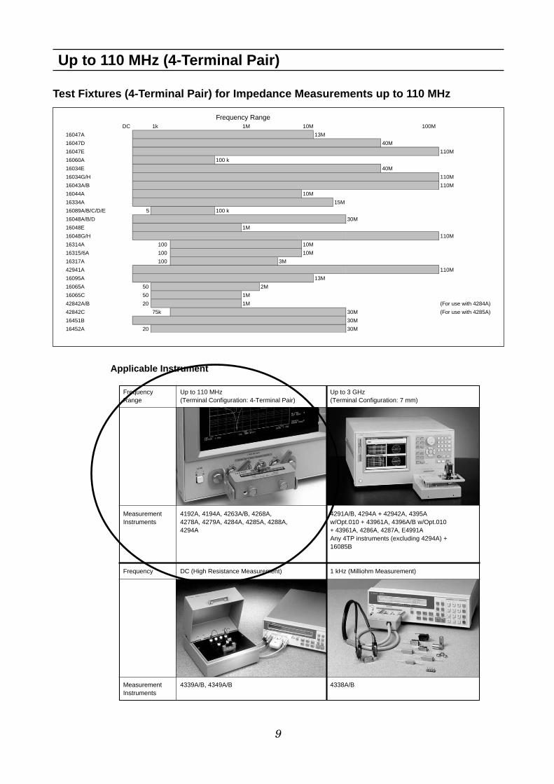
Test Fixtures (4-Terminal Pair) for Impedance Measurements up to 110 MHz
Up to 110 MHz (4-Terminal Pair)
9
Frequency RangeDC 1k 1M 10M 100M
16047A 13M
16047D 40M
16047E 110M
16060A 100 k
16034E 40M
16034G/H 110M
16043A/B 110M
16044A 10M
16334A 15M
16089A/B/C/D/E 5 100 k
16048A/B/D 30M
16048E 1M
16048G/H 110M
16314A 100 10M
16315/6A 100 10M
16317A 100 3M
42941A 110M
16095A 13M
16065A 50 2M
16065C 50 1M
42842A/B 20 1M (For use with 4284A)
42842C 75k 30M (For use with 4285A)
16451B 30M
16452A 20 30M
Frequency Up to 110 MHz Up to 3 GHzRange (Terminal Configuration: 4-Terminal Pair) (Terminal Configuration: 7 mm)
Measurement 4192A, 4194A, 4263A/B, 4268A, 4291A/B, 4294A + 42942A, 4395A Instruments 4278A, 4279A, 4284A, 4285A, 4288A, w/Opt.010 + 43961A, 4396A/B w/Opt.010
4294A + 43961A, 4286A, 4287A, E4991AAny 4TP instruments (excluding 4294A) +16085B
Frequency DC (High Resistance Measurement) 1 kHz (Milliohm Measurement)
Measurement 4339A/B, 4349A/B 4338A/BInstruments
Applicable Instrument

Up to 110 MHz (4-Terminal Pair) Lead Components
10
16047A Test Fixture
Terminal Connector: 4-Terminal Pair, BNC
DUT Connection: 4-Terminal
Dimensions (approx.):124 (W) x 31 (H) x 62 (D) mm
Weight (approx.): 205 g
Additional Error:
f: [MHz]
Description: This test fixture is designed for impedanceevaluation of axial/radial lead type devices. The 16047A employs Kelvin contacts which realize a wideimpedance measurement range. The contact tip can bechanged according to the device shape.Applicable Instruments: 4263B, 4268A, 4279A, 4284A,4285A, 4288A, 4294A, (4192A, 4194A, 4263A, 4278A)** denotes the instrument is obsolete.Frequency: DC to 13 MHz Maximum Voltage: ±40 V peak max (AC+DC)Operating Temperature: 0°C to 55°C DUT Size: See figure with module sizes.
Furnished Accessories:
Each module size for the 16047A/D is shown above.
Option:16047A-701: Add Shorting Plate P/N 5000-4226Compensation and Measurement: Select one of thesemodules suitable for the DUT’s shape. Open and shortcompensations are recommended before measurement.Short compensation is performed by shorting the contactsof the test fixture with a shorting plate. After performingopen and short compensations, the DUT is connected tothe test fixture.
16047A, 16047D module sizes
P/N 5000-4226
Shorting plate
Description P/N Qty.Module For Axial Lead 16061-70022 2Module For Radial Lead mounting on fixture 16061-70021 2Module For Short Radial Lead 16047-65001 2Operating Note 16047-90011 1
Type of Error Impedance
Proportional Error ±5 x (f/10)2
Material:Brass (Ni-dipped)Thickness:1.0 mmResidual impedance:20nH, 1mΩ

16047D Test Fixture
Terminal Connector: 4-Terminal Pair, BNC
DUT Connection: 2-Terminal
Dimensions (approx.):149 (W) x 40 (H) x 72 (D) [mm]
Weight (approx.): 230 g
Additional Error:
f: [MHz]
11
Up to 110 MHz (4-Terminal Pair) Lead Components
Description: This test fixture is designed for impedanceevaluation of axial/radial lead type devices. The 16047Dcan be used up to a higher frequency, 40 MHz.Applicable Instruments: 4263B, 4268A, 4279A, 4284A,4285A, 4288A, 4294A, (4192A, 4194A, 4263A, 4278A)** denotes the instrument is obsolete.Frequency: DC to 40 MHzMaximum Voltage: ±40 V peak max (AC+DC)Operating Temperature: 0°C to 55°C DUT Size: See the 16047A figure with module sizes.Furnished Accessories:
Option:16047A-701: Add Shorting Plate P/N 5000-4226Compensation and Measurement: Open and shortcompensations are recommended before measurement.Short compensation is performed by shorting the contactsof the test fixture with a shorting plate. After performingopen and short compensations, the DUT is connected tothe test fixture.
Type of Error Impedance
Proportional Error ±1.25 x (f/10)2
Description P/N Qty.
Module For Axial Lead 16061-70022 2
Module For Radial Lead mounting on fixture 16061-70021 2
Module For Short Radial Lead 16047-65001 2
Operating Note 16047-90300 1

16047E Test Fixture
Terminal Connector: 4-Terminal Pair, BNC
DUT Connection: 2-Terminal
Dimensions (approx.):135 (W) x 40 (H) x 65 (D) [mm]
Weight (approx.): 200 g
Additional Error:
f: [MHz]
12
Up to 110 MHz (4-Terminal Pair) Lead Components
Test fixture overview Connecting a shorting plate Measuring 3-Terminal device
Description: This test fixture is designed for impedanceevaluation of lead type devices up to 110 MHz. A guardterminal is available for three terminal devices and ashorting plate comes secured on this fixture.Applicable Instruments: 4263B, 4268A, 4279A, 4284A,4285A, 4288A, 4294A, (4192A, 4194A, 4263A, 4278A)** denotes the instrument is obsolete.Frequency: DC to 110 MHzMaximum Voltage: ±42 V peak max.(AC+DC)Operating Temperature: 0°C to 55°C DUT Size: See figure below with 16047E’s electrode size.
Furnished Accessories:
Compensation and Measurement: Open and shortcompensations are recommended before measurement.Short compensation is performed by shorting the contactsof the test fixture with a shorting plate. After performingopen and short compensations, the DUT is connected tothe test fixture. The following figures show howcompensation and measurement are performed.
Type of Error ImpedanceProportional Error f <= 15 MHz 0.2 x (f/10)2[%]
Proportional Error f > 15 MHz 4 x (f/100)[%]
Open Repeatability 2 n+10 µ x (f/100) [S]Short Repeatability 2 m+600 m x (f/100) [Ω]
Description P/N Qty.
Angle(right-side) NA 1
Angle(left-side) NA 1
Screws 0515-0914 4
Shorting Plate 16047-00621 1
Operation and Service Manual 16047-90040 1

16060A Transformer Test Fixture
Terminal Connector: 4-Terminal Pair, BNC
DUT Connection:2-Terminal for L measurement
3-Terminal for N, M measurement
See figure below for more information.
Dimensions (approx.):90 (W) x 35 (H) x 90 (D) [mm]
Cable Length (approx.): 25cm
Weight (approx.): 300 g
Additional Error: The additional error is negligible when
compared to the instrument’s accuracy.
13
Up to 110 MHz (4-Terminal Pair) Lead Components
Description: This test fixture provides a convenientmeans of measuring a transformer’s self-inductance,mutual inductance, turns-ratio, and dc resistance in thefrequency range of dc to 100 kHz, as appropriate for eachmeasurement.Applicable Instruments: 4263A*/B (with Option 4263B-001) OnlyFrequency: DC to 100 kHzOperating Temperature: 0°C to 55°C DUT Size: The lead wire of the transformer should nothave a diameter greater than 4 mm, otherwise the alliga-tor clip will not be able to clamp onto it properly.Furnished Accessories:
Compensation and Measurement: Open compensationis recommended before measurement. Open compensationis performed by connecting the alligator clips of “A” and “B”terminals together and separating them from the likewiseconnected alligator clips of the COMMON terminals.After performing open compensation, the transformer isconnected to the test fixture. The “A” and “B” terminalsare connected to the high terminals of the transformer.The COMMON terminals are connected to the lowterminals of the transformer. The following figures showhow compensation and measurement are performed.
Open compensation Connecting a transformer
Description P/N Qty.
Test Leads (black), Alligator clip to BNC(m) 16060-61601 2
Test Leads (red), Alligator clip to BNC(m) 16060-61602 2
Operation and Service Manual 16060-90000 1
4263B with 16060A

16034E Test Fixture
Terminal Connector: 4-Terminal Pair, BNC
DUT Connection: 2-Terminal
Dimensions (approx.):128 (W) x 60 (H) x 71 (D) [mm]
Weight (approx.): 270 g
Additional Error:
f: [MHz]
14
Up to 110 MHz (4-Terminal Pair) SMD
Description: This test fixture is designed for impedanceevaluations of SMD. The minimum SMD size that this fix-ture is adapted to evaluate is 1.6(L) x 0.8(W) [mm].Applicable Instruments: 4263B, 4268A, 4279A, 4284A,4285A, 4288A, 4294A, (4192A, 4194A, 4263A, 4278A)** denotes the instrument is obsolete.Frequency: DC to 40 MHz Maximum Voltage: ±40 V peak max (AC+DC)Operating Temperature: 0°C to 55°C DUT Size: See figure below
Furnished Accessories:
Compensation and Measurement: Open and shortcompensations are recommended before measurement.Open compensation is performed by separating the highand low electrodes from each other. The separationshould be equivalent in size to the DUT’s width. Shortcompensation is performed by contacting the high and lowelectrodes together. After performing open and short com-pensations, the DUT is inserted into the test fixture. Thefollowing figures show how compensation and measure-ment are performed.
Open compensation Short compensation
Inserting a DUT Electrode dimensions
Type of Error Impedance
Proportional Error ±1.5 x (f/10)2
Description P/N Qty.
Operating Manual 16034-90041 1
DUT Dimensions

16034G Test Fixture
Terminal Connector: 4-Terminal Pair, BNC
DUT Connection: 2-Terminal
Dimensions (approx.):120(W) x 50(H) x 70(D) [mm]
Weight (approx.): 200 g
Additional Error:
f: [MHz]
15
Up to 110 MHz (4-Terminal Pair) SMD
Open compensation Short compensation
DimensionsDUT measurement
Description: This test fixture is designed for impedanceevaluations of SMD. The minimum SMD size that this fixtureis adapted to evaluate is 0.6(L) x 0.3(W) [mm].Applicable Instruments: 4263B, 4268A, 4279A, 4284A,4285A, 4288A, 4294A, (4192A, 4194A, 4263A, 4278A)** denotes the instrument is obsolete.Frequency: DC to 110 MHz Maximum Voltage: ±40 V peak max (AC+DC)Operating Temperature: 0°C to 55°C DUT Size: See figure below
Furnished Accessories:
Compensation and Measurement: Open and shortcompensations are recommended before measurement. Whenmeasuring above 3 MHz, load compensation is alsorecommended. Open compensation is performed by separatingthe high and the low electrodes from each other. Theseparation size should be equivalent to the DUT’s width.Short compensation is performed placing the high and lowelectrodes in contact together. Load compensation isperformed by using the furnished 100 Ω SMD chip resistor.After performing open, short and load compensations, theDUT is inserted into the test fixture. The following figuresshow how compensation and measurement are performed.
Type of Error Impedance
Proportional Error 0.5 x (f/10)2[%]
Open Repeatability 5 + 500 x (f/10) [nS]
Short Repeatability 10 + 13 x (f/10) [mΩ]
4284A with 16034G
Description P/N Qty.
Case for 100 Ω SMD Resistance 1540-0692 1
100Ω Chip Resistor 0699-2488 10
Operation Manual 16034-90011 1
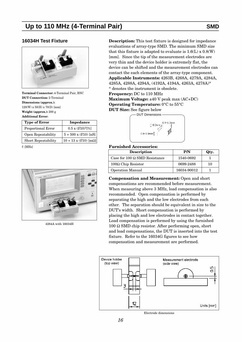
16034H Test Fixture
Terminal Connector: 4-Terminal Pair, BNC
DUT Connection: 2-Terminal
Dimensions (approx.):120(W) x 50(H) x 70(D) [mm]
Weight (approx.): 200 g
Additional Error:
f: [MHz]
16
Up to 110 MHz (4-Terminal Pair) SMD
4284A with 16034H
Electrode dimensions
Type of Error Impedance
Proportional Error 0.5 x (f/10)2[%]
Open Repeatability 5 + 500 x (f/10) [nS]
Short Repeatability 10 + 13 x (f/10) [mΩ]
Description: This test fixture is designed for impedanceevaluations of array-type SMD. The minimum SMD sizethat this fixture is adapted to evaluate is 1.6(L) x 0.8(W)[mm]. Since the tip of the measurement electrodes arevery thin and the device holder is extremely flat, thedevice can be shifted and the measurement electrodes cancontact the each elements of the array-type component.Applicable Instruments: 4263B, 4268A, 4279A, 4284A,4285A, 4288A, 4294A, (4192A, 4194A, 4263A, 4278A)** denotes the instrument is obsolete.Frequency: DC to 110 MHz Maximum Voltage: ±40 V peak max (AC+DC)Operating Temperature: 0°C to 55°C DUT Size: See figure below
Furnished Accessories:
Compensation and Measurement: Open and shortcompensations are recommended before measurement.When measuring above 3 MHz, load compensation is alsorecommended. Open compensation is performed byseparating the high and the low electrodes from eachother. The separation should be equivalent in size to theDUT’s width. Short compensation is performed byplacing the high and low electrodes in contact together.Load compensation is performed by using the furnished100 Ω SMD chip resistor. After performing open, shortand load compensations, the DUT is inserted into the testfixture. Refer to the 16034G figures to see howcompensation and measurement are performed.
Description P/N Qty.
Case for 100 Ω SMD Resistance 1540-0692 1
100Ω Chip Resistor 0699-2488 10
Operation Manual 16034-90012 1
DUT Dimensions

16044A Test Fixture
Terminal Connector: 4-Terminal Pair, BNC
DUT Connection: 4-Terminal
Dimensions (approx.):160(W) x 70(H) x 98(D) [mm]
Weight (approx.): 550 g
Additional Error:
f: [MHz]
17
Up to 110 MHz (4-Terminal Pair) SMD
Description: This test fixture is designed for impedanceevaluations of low impedance SMD. The minimum SMDsize that this fixture is adapted to evaluate is 1.6(L) x0.8(W) [mm]. The 16044A has a Kelvin (4-Terminal)contact, which ensures repeatable measurements. It isalso equipped with a mechanism for easily performingopen and short compensation.Applicable Instruments: 4263B, 4268A, 4279A, 4284A,4285A, 4288A, 4294A, (4192A, 4194A, 4263A, 4278A)** denotes the instrument is obsolete.Frequency: DC to 10 MHz Maximum Voltage: ±40 V peak max (AC+DC)Operating Temperature: 0°C to 55°CDUT Size: See figure below
Furnished Accessories:
To maintain the measurement precision, it isrecommended that contact pins be replaced approximatelyevery 50,000 times (supplementary value).
Type of Error Impedance
Proportional Error 2 x (f/10)2[%]
Open Repeatability 1.5 + 200 x (f/10) [nS]
Short Repeatability 1.5 + 40 x (f/10) [mΩ]
Description P/N Qty.
Cleaning Rod 5182-7586 1
Operation and Service Manual 16044-90020 1
Test fixture overview

18
Up to 110 MHz (4-Terminal Pair) SMD
Electrode dimensions
Short compensationOpen compensation Inserting a DUT
Compensation and Measurement: Open and shortcompensations are recommended before measurement.Short compensation is performed by bringing down theshorting plate (which is already on the fixture) to short all4 terminals. Open compensation is performed by bringingdown both the open plate and the shorting plate toseparate the high terminals from the low terminals. Afterperforming open and short compensations, the DUT isinserted into the test fixture. The figures below show howcompensation and measurement are performed.
Diameter of probe pin is 0.19 mmDiameter of Blade electrode’s contact spot is 0.5 mmSpacing between Blade electrode and probe pin is 0.11 mm
SMD can be between 1.6 and 8.0 mm in width
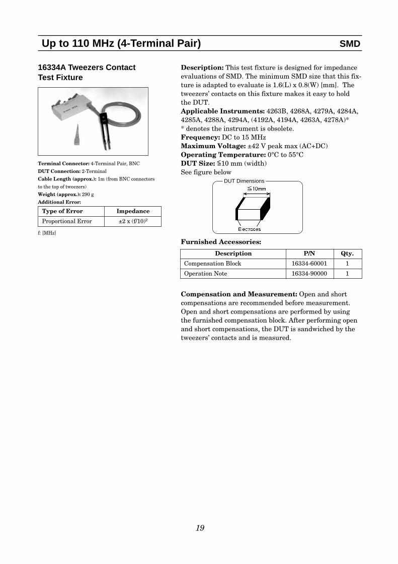
16334A Tweezers Contact Test Fixture
Terminal Connector: 4-Terminal Pair, BNC
DUT Connection: 2-Terminal
Cable Length (approx.): 1m (from BNC connectors
to the top of tweezers)
Weight (approx.): 290 g
Additional Error:
f: [MHz]
19
Up to 110 MHz (4-Terminal Pair) SMD
Type of Error Impedance
Proportional Error ±2 x (f/10)2
Description: This test fixture is designed for impedanceevaluations of SMD. The minimum SMD size that this fix-ture is adapted to evaluate is 1.6(L) x 0.8(W) [mm]. Thetweezers’ contacts on this fixture makes it easy to holdthe DUT.Applicable Instruments: 4263B, 4268A, 4279A, 4284A,4285A, 4288A, 4294A, (4192A, 4194A, 4263A, 4278A)** denotes the instrument is obsolete.Frequency: DC to 15 MHz Maximum Voltage: ±42 V peak max (AC+DC)Operating Temperature: 0°C to 55°C DUT Size: <=10 mm (width) See figure below
Furnished Accessories:
Compensation and Measurement: Open and shortcompensations are recommended before measurement.Open and short compensations are performed by usingthe furnished compensation block. After performing openand short compensations, the DUT is sandwiched by thetweezers’ contacts and is measured.
Description P/N Qty.
Compensation Block 16334-60001 1
Operation Note 16334-90000 1
DUT Dimensions

16043A/B3-Terminal SMD Test Fixture
Terminal Connector: 4-Terminal Pair, BNC
DUT Connection:3-Terminal (including the guard terminal)
Dimensions (approx.):75 (W) x 105 (H) x 95 (D) [mm]
Weight (approx.): 500 g (16043A)
330 g (16043B)
Additional Error:
Guard Terminal Residual L: ≤6 nH
Guard Terminal Residual R: ≤20 mΩ
The additional error shown above is the
characteristics of when the DUT connection
is 2-Terminal. Ideally, in a 3-Terminal DUT
connection, the guard effect should be taken
into account in the measurement accuracy.
To acknowledge the guard terminal’s effect,
a characteristics equation is provided in the
operation manual.
20
Up to 110 MHz (4-Terminal Pair) SMD
Type of Error ImpedanceProportional Error 0.4 + 7.2 x (f/100)2[%]Open Repeatability 10 + 600 x (f/10) [nS]Short Repeatability 30 + 6 x (f/10) [mΩ]
Description: The 16043A/B enable 3-Terminal resonatorSMD to be measured by using the guarding technique.Having a 4-Terminal Pair configuration it ensures highprecision and repeatability. The 16043A/B accommodatesa wide range of SMD sizes by providing 3 different contactboards. The 16043A is equipped with a sliding mecha-nism to enable the measurement of load capacitors in the3-Terminal resonator. The 16043B is not equipped withthe sliding mechanism. 2-Terminal SMD with bottomelectrodes can be measured as well. As shown in the fig-ure below, by connecting the device’s G-terminal to instru-ment’s guard terminal, only Z1 or the resonator will bemeasured.
In order to measure Z2 and Z3, the sliding function of16043A can be utilized.
Applicable Instruments: 4263B, 4268A, 4279A, 4284A,4285A, 4288A, 4294A, (4192A, 4194A, 4263A, 4278A)** denotes the instrument is obsolete.Frequency: DC to 110 MHzOperating Temperature: 0°C to 70˚CDUT Size: The applicable DUT dimensions are shownbelow. A contact board is required for measurement andits dimensions and ordering info are shown on the nextpage.
Guarding technique of an impedance measurement instrument
Electrode configuration of DUT and applicable DUT dimensions

DUT Size:
Three types of contact boards are provided for the 16043A/B and the contact boards are selected accord-ingly to the DUT size and electrodes’ separation. The electrode spacings on the contact boards are shownin the figure above. The 16043A’s contact boards are provided with three groups of electrodes (as shownin the figure above) and the sliding mechanism allows the DUT to slide down to the next group of elec-trode. In order to lay the DUT at an appropriate position on the contact board, a device guide fabricatedto fit the size of the DUT is required.
Select the contact boards, that accommodates the DUT size best.The table to the left shows the applicable DUT sizes for eachcontact board.
Furnished Accessories:
Options*:16043A/B-001: Add Contact Board No.1 P/N 16043-66501 (16043A)/16043-66511 (16043B)16043A/B-002: Add Contact Board No.2 P/N 16043-66502 (16043A)/16043-66512 (16043B)16043A/B-003: Add Contact Board No.3 P/N 16043-66503 (16043A)/16043-66513 (16043B)16043A/B-004: Add Additional Device Guide P/N 16043-00601
*At least one option (16043A/B-001/002/003) must be ordered for 16043A or 16043B.
To maintain the measurement precision, it is recommended to clean the contact boards approximatelyevery 1,000 times. It is recommended to replace the contact boards approximately every 10,000 times.
21
Up to 110 MHz (4-Terminal Pair) SMD
Description P/N Qty.Support Angle for the 4294A 16043-01203 1Device Guide 16043-00601 3Screws for the Device Guide 0515-2791 2Guide Pin 16043-24004 2Support Angle 16043-01212 1Tweezer 8710-2081 1Positioning Tool (16043B only) 16043-00607 1Carrying Case 16043-60150/60250 1Operation and Service Manual 16043-90000 1
Contact BoardApplicableDUT Size
No.18.1 mm × 4.5 mm to 3.7 mm × 3.1 mm
No.23.7 mm × 3.1 mm to 2.5 mm × 2.0 mm
No.32.5 mm × 2.0 mm to 2.0 mm × 1.2 mm
Electrode configuration for 16043A/B contact board

22
Compensation and Measurement:Before measurement, a device guide,which is fabricated to fit the DUT’s sizemust be prepared. A pre-fabricated deviceguide is furnished and the method ofpreparation is described in the operationmanual. The contact board and the deviceguide must be connected to the 16043A/B.This is easily accomplished by using thefurnished guide pin and screws. For high-ly precise measurements, it is recommend-ed to perform open and short compensa-tion. Open compensation is performed, byplacing nothing between the high and lowterminals of the contact board. For shortcompensation, short the high and low ter-minals and do not contact the G terminalwith the short bar. It is necessary to con-struct a short bar, which matches theDUT’s size. The following figures showhow compensation and measurement areperformed.
Up to 110 MHz (4-Terminal Pair) SMD
Test fixture overview
Performing short compensation
The sliding mechanism of the 16043A allows themeasurement of the load capacitors, by sliding theDUT and the device guide to the next electrode onthe contact board. It is necessary, to raise the pres-sure arm before the DUT is moved.
1. Place the short bar on the electrodes. Make sure that the short bar does not connect the Gterminal.
2. Lower the pressure arm to hold the short bar in place. 3. Perform short compensation data measurement.
1. Align the DUT with the device guide and place it onthe contact board.
2. Lower the pressure arm to hold the DUT in place. 3. Adjust the contact pressure using the pressure regulat-
ing screw.4. Measure.
Inserting a DUT
Sliding mechanism for 16043A

23
Up to 110 MHz (4-Terminal Pair) Other Components
16089A Large Kelvin Clip Leads
Terminal Connector:4-Terminal Pair, BNC
DUT Connection: 4-Terminal
Cable Length (approx.):0.94m (from connector to clip's tip)
Weight (approx.): 300 g
Additional Error: The additional error
is negligible when compared to the
instrument's accuracy.
Description: This test fixture makes it possible to mea-sure odd-shaped components that cannot be measuredwith conventional fixtures. It is equipped with two insu-lated Kelvin clips. Applicable Instruments: 4263B, 4268A, 4279A, 4284A,4285A, 4288A, 4294A, (4192A, 4194A, 4263A, 4278A)** denotes the instrument is obsolete.Frequency: 5 Hz to 100 kHz Maximum Voltage: ±42 V peak max (AC+DC)Operating Temperature: 0°C to 55°C DUT Size:See figure below
Furnished Accessories:
Compensation and Measurement: Open and shortcompensations are recommended before measurement.For open compensation, do not connect the Kelvin clips toanything. Short compensation is performed by holding ashorting plate with the Kelvin clips. After performingopen and short compensations, the DUT is held with theKelvin clips.
16089B Medium Kelvin Clip Leads
Terminal Connector: 4-Terminal Pair, BNC
DUT Connection: 4-Terminal
Cable Length (approx.):0.94m (from connector to clip's tip)
Weight (approx.): 300 g
Additional Error: The additional error is
negligible when compared to the instrument's
accuracy.
Description P/N Qty.
Operation and Service Manual 16089-90000 1
Description: This test fixture makes it possible to mea-sure odd-shaped components that cannot be measuredwith conventional fixtures. It is equipped with two insu-lated Kelvin clips. Applicable Instruments: 4263B, 4268A, 4279A, 4284A,4285A, 4288A, 4294A, (4192A, 4194A, 4263A, 4278A)** denotes the instrument is obsolete.Frequency: 5 Hz to 100 kHz Maximum Voltage: ±42 V peak max (AC+DC)Operating Temperature: 0°C to 55°C DUT Size: See figure below
Furnished Accessories:
Compensation and Measurement: Open and shortcompensations are recommended before measurement.For open compensation, do not connect the Kelvin clips toaynthing. Short compensation is performed by connectingthe Kelvin clips together. After performing open and shortcompensations, the DUT is held with the Kelvin clips.
Description P/N Qty.
Operation and Service Manual 16089-90000 1

24
Up to 110 MHz (4-Terminal Pair) Other Components
16089C Kelvin IC Clip Leads
Terminal Connector: 4-Terminal Pair, BNC
DUT Connection: 4-Terminal
Cable Length (approx.):1.3m (from connector to clip's tip)
Weight (approx.): 300 g
Additional Error: The additional error is
negligible when compared to the instrument's
accuracy.
Description: This test fixture makes it possible to measure odd-shaped components that cannot be measured with conventional fixtures. It is equipped withtwo insulated Kelvin clips. Applicable Instruments: 4263B, 4268A, 4279A, 4284A,4285A, 4288A, 4294A, (4192A, 4194A, 4263A, 4278A)** denotes the instrument is obsolete.Frequency: 5 Hz to 100 kHz Maximum Voltage: ±42 V peak max (AC+DC)Operating Temperature: 0°C to 55°CDUT Size:See figure below
Furnished Accessories:
Compensation and Measurement: Open and shortcompensations are recommended before measurement.For open compensation, do not connect the Kelvin clips toanything. Short compensation is performed by connectingthe Kelvin clips together. After performing open and shortcompensations, the DUT is held with the Kelvin clips.
16089D Kelvin Alligator Clip Leads
Terminal Connector: 4-Terminal Pair, BNC
DUT Connection: 4-Terminal
Cable Length (approx.):0.94m (from connector to clip's tip)
Weight (approx.): 460 g
Additional Error: The additional error is
negligible when compared to the instrument's
accuracy.
Description P/N Qty.
Operation and Service Manual 16089-90000 1
Description: This test fixture makes it possible to measure odd-shaped components that cannot be measured with conventional fixtures. It is equipped withfour alligator clips. Applicable Instruments: 4263B, 4268A, 4279A, 4284A,4285A, 4288A, 4294A, (4192A, 4194A, 4263A, 4278A)** denotes the instrument is obsolete.Frequency: 5 Hz to 100 kHz Maximum Voltage: ±42 V peak max (AC+DC)Operating Temperature: 0°C to 55°CDUT Size: diameter of DUT's leads ≤ 5 mmFurnished Accessories:
Compensation and Measurement: Open and shortcompensations are recommended before measurement.For open compensation, do not connect the alligator clipsto anything. Short compensation is performed by holdinga shorting plate with the alligator clips. Make sure thatthe alligator clips with the "V" markers are next to eachother. After performing open and short compensations,the DUT is held with the alligator clips. Connect the samecolor test clips to the same terminal of the DUT and havethe clips with "V" markers be closer to the DUT.
Description P/N Qty.
Operation and Service Manual 16089-90000 1
DUT Dimensions
25
Up to 110 MHz (4-Terminal Pair) Other Components
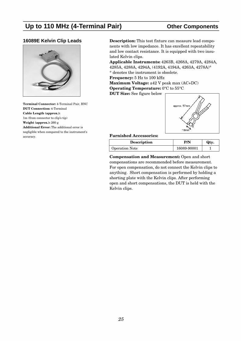
16089E Kelvin Clip Leads
Terminal Connector: 4-Terminal Pair, BNC
DUT Connection: 4-Terminal
Cable Length (approx.):1m (from connector to clip's tip)
Weight (approx.): 260 g
Additional Error: The additional error is
negligible when compared to the instrument's
accuracy.
Description: This test fixture can measure lead compo-nents with low impedance. It has excellent repeatabilityand low contact resistance. It is equipped with two insu-lated Kelvin clips.Applicable Instruments: 4263B, 4268A, 4279A, 4284A,4285A, 4288A, 4294A, (4192A, 4194A, 4263A, 4278A)** denotes the instrument is obsolete.Frequency: 5 Hz to 100 kHz Maximum Voltage: ±42 V peak max (AC+DC)Operating Temperature: 0°C to 55°CDUT Size: See figure below
Furnished Accessories:
Compensation and Measurement: Open and shortcompensations are recommended before measurement.For open compensation, do not connect the Kelvin clips toanything. Short compensation is performed by holding ashorting plate with the Kelvin clips. After performingopen and short compensations, the DUT is held with theKelvin clips.
Description P/N Qty.
Operation Note 16089-90001 1
26
Up to 110 MHz (4-Terminal Pair) Port/Cable Extension
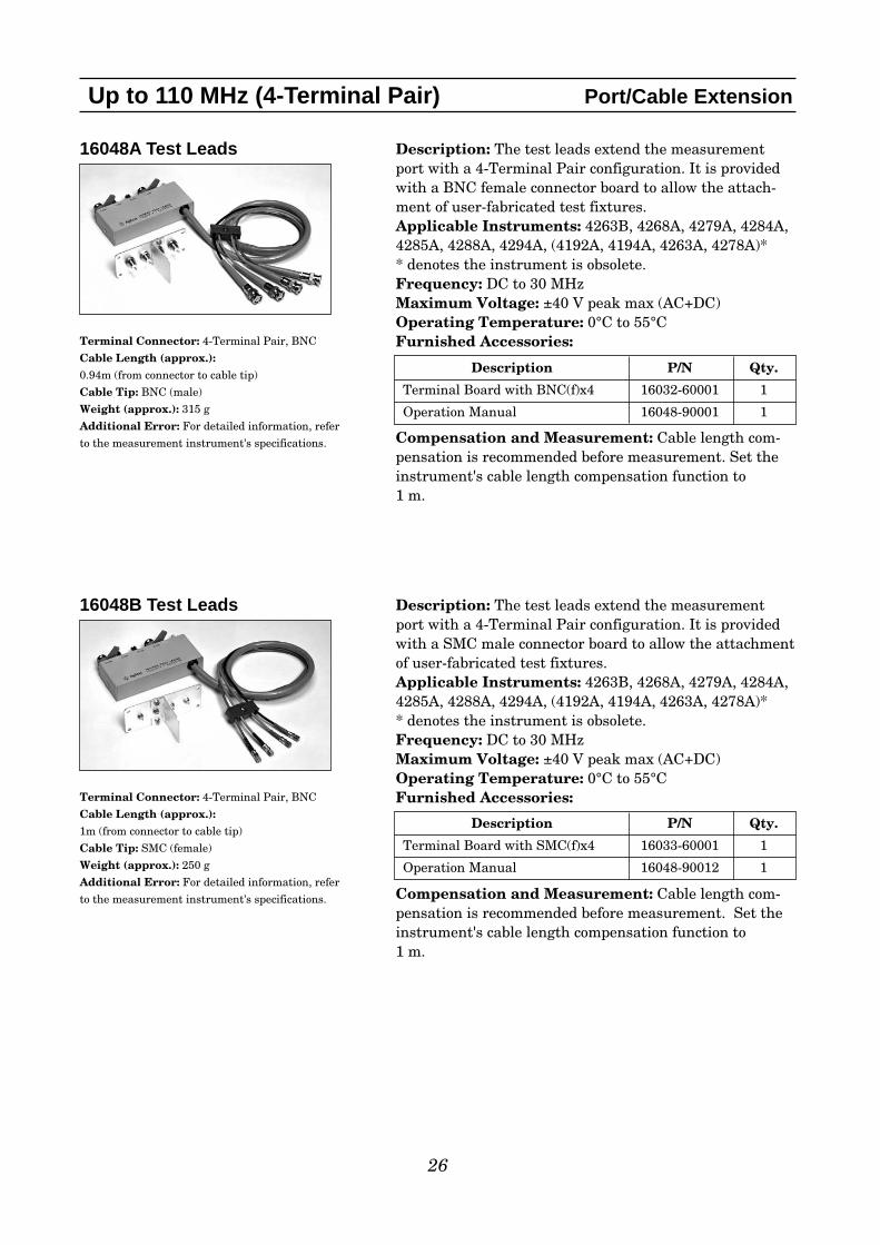
16048A Test Leads
Terminal Connector: 4-Terminal Pair, BNC
Cable Length (approx.):0.94m (from connector to cable tip)
Cable Tip: BNC (male)
Weight (approx.): 315 g
Additional Error: For detailed information, refer
to the measurement instrument's specifications.
Description: The test leads extend the measurementport with a 4-Terminal Pair configuration. It is providedwith a BNC female connector board to allow the attach-ment of user-fabricated test fixtures.Applicable Instruments: 4263B, 4268A, 4279A, 4284A,4285A, 4288A, 4294A, (4192A, 4194A, 4263A, 4278A)** denotes the instrument is obsolete.Frequency: DC to 30 MHz Maximum Voltage: ±40 V peak max (AC+DC)Operating Temperature: 0°C to 55°CFurnished Accessories:
Compensation and Measurement: Cable length com-pensation is recommended before measurement. Set theinstrument's cable length compensation function to 1 m.
Description P/N Qty.
Terminal Board with BNC(f)x4 16032-60001 1
Operation Manual 16048-90001 1
16048B Test Leads
Terminal Connector: 4-Terminal Pair, BNC
Cable Length (approx.): 1m (from connector to cable tip)
Cable Tip: SMC (female)
Weight (approx.): 250 g
Additional Error: For detailed information, refer
to the measurement instrument's specifications.
Description: The test leads extend the measurementport with a 4-Terminal Pair configuration. It is providedwith a SMC male connector board to allow the attachmentof user-fabricated test fixtures.Applicable Instruments: 4263B, 4268A, 4279A, 4284A,4285A, 4288A, 4294A, (4192A, 4194A, 4263A, 4278A)** denotes the instrument is obsolete.Frequency: DC to 30 MHz Maximum Voltage: ±40 V peak max (AC+DC)Operating Temperature: 0°C to 55°CFurnished Accessories:
Compensation and Measurement: Cable length com-pensation is recommended before measurement. Set theinstrument's cable length compensation function to 1 m.
Description P/N Qty.
Terminal Board with SMC(f)x4 16033-60001 1
Operation Manual 16048-90012 1
27
Up to 110 MHz (4-Terminal Pair) Port/Cable Extension
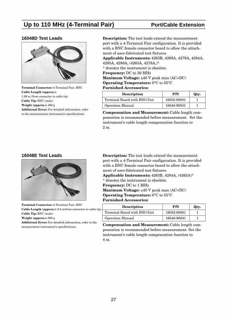
16048D Test Leads
Terminal Connector: 4-Terminal Pair, BNC
Cable Length (approx.):1.89 m (from connector to cable tip)
Cable Tip: BNC (male)
Weight (approx.): 460 g
Additional Error: For detailed information, refer
to the measurement instrument's specifications.
Description: The test leads extend the measurementport with a 4-Terminal Pair configuration. It is providedwith a BNC female connector board to allow the attach-ment of user-fabricated test fixtures.Applicable Instruments: 4263B, 4268A, 4279A, 4284A,4285A, 4288A, (4263A, 4278A,)** denotes the instrument is obsolete.Frequency: DC to 30 MHz Maximum Voltage: ±40 V peak max (AC+DC)Operating Temperature: 0°C to 55°CFurnished Accessories:
Compensation and Measurement: Cable length com-pensation is recommended before measurement. Set theinstrument's cable length compensation function to 2 m.
Description P/N Qty.
Terminal Board with BNC(f)x4 16032-60001 1
Operation Manual 16048-90031 1
16048E Test Leads
Terminal Connector: 4-Terminal Pair, BNC
Cable Length (approx.): 3.8 m(from connector to cable tip)
Cable Tip: BNC (male)
Weight (approx.): 690 g
Additional Error: For detailed information, refer to the
measurement instrument's specifications.
Description: The test leads extend the measurementport with a 4-Terminal Pair configuration. It is providedwith a BNC female connector board to allow the attach-ment of user-fabricated test fixtures.Applicable Instruments: 4263B, 4284A, (4263A)** denotes the instrument is obsolete.Frequency: DC to 1 MHz Maximum Voltage: ±40 V peak max (AC+DC)Operating Temperature: 0°C to 55°CFurnished Accessories:
Compensation and Measurement: Cable length com-pensation is recommended before measurement. Set theinstrument's cable length compensation function to 4 m.
Description P/N Qty.
Terminal Board with BNC(f)x4 16032-60001 1
Operation Manual 16048-90041 1
28
Up to 110 MHz (4-Terminal Pair) Port/Cable Extension
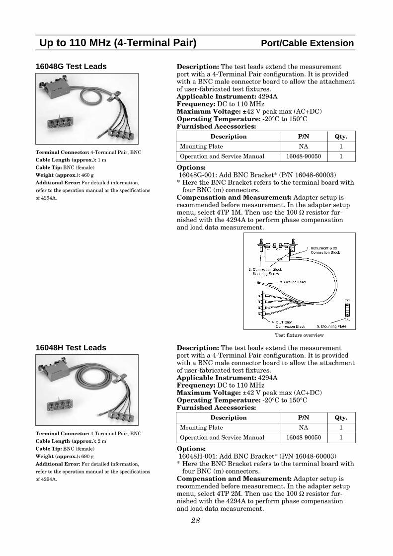
16048G Test Leads
Terminal Connector: 4-Terminal Pair, BNC
Cable Length (approx.): 1 m
Cable Tip: BNC (female)
Weight (approx.): 460 g
Additional Error: For detailed information,
refer to the operation manual or the specifications
of 4294A.
Description: The test leads extend the measurementport with a 4-Terminal Pair configuration. It is providedwith a BNC male connector board to allow the attachmentof user-fabricated test fixtures.Applicable Instrument: 4294AFrequency: DC to 110 MHz Maximum Voltage: ±42 V peak max (AC+DC)Operating Temperature: -20°C to 150°CFurnished Accessories:
Options:16048G-001: Add BNC Bracket* (P/N 16048-60003)* Here the BNC Bracket refers to the terminal board with
four BNC (m) connectors.Compensation and Measurement: Adapter setup isrecommended before measurement. In the adapter setupmenu, select 4TP 1M. Then use the 100 Ω resistor fur-nished with the 4294A to perform phase compensationand load data measurement.
Description P/N Qty.
Mounting Plate NA 1
Operation and Service Manual 16048-90050 1
16048H Test Leads
Terminal Connector: 4-Terminal Pair, BNC
Cable Length (approx.): 2 m
Cable Tip: BNC (female)
Weight (approx.): 690 g
Additional Error: For detailed information,
refer to the operation manual or the specifications
of 4294A.
Description: The test leads extend the measurementport with a 4-Terminal Pair configuration. It is providedwith a BNC male connector board to allow the attachmentof user-fabricated test fixtures.Applicable Instrument: 4294AFrequency: DC to 110 MHz Maximum Voltage: ±42 V peak max (AC+DC)Operating Temperature: -20°C to 150°CFurnished Accessories:
Options:16048H-001: Add BNC Bracket* (P/N 16048-60003)* Here the BNC Bracket refers to the terminal board with
four BNC (m) connectors.Compensation and Measurement: Adapter setup isrecommended before measurement. In the adapter setupmenu, select 4TP 2M. Then use the 100 Ω resistor fur-nished with the 4294A to perform phase compensationand load data measurement.
Description P/N Qty.
Mounting Plate NA 1
Operation and Service Manual 16048-90050 1
Test fixture overview

16314A Balanced/Unbalanced 4-Terminal Converter
Terminal Connector: 4-Terminal Pair, BNC
(unbalanced)
DUT Connection: 3 binding posts (balanced)
Dimensions (approx.):89 (W) x 56 (H) x 133 (D) [mm]
Weight (approx.): 400 g
Additional Error:
(Typical Data)
29
Up to 110 MHz (4-Terminal Pair) Balanced/Unbalanced Converters
Description: This balun converts the (unbalanced) 4-Terminal pair configuration to a (balanced) binding postsconfiguration. It is used to measure a balanced deviceusing an unbalanced measurement instrument.Applicable Instruments: 4263B, 4268A, 4279A, 4284A,4285A, 4288A, 4294A, (4192A, 4194A, 4263A, 4278A)** denotes the instrument is obsolete.Frequency: 100 Hz to 10 MHz Nominal Characteristic Impedance:Unbalanced Side: 50 ΩBalanced Side: 50 Ω
Insertion Loss: ≤1.0 dB (@ 23°C±5°C, 100 kHz)Frequency Response: ≤ ±1.0 dB (@ 23°C±5°C, 100 kHz)
specified @ 23°C±5°COperating Temperature: 0°C to 55°CDUT Size: Terminal spacingof balanced side: 14 mm
Furnished Accessories:
Compensation and Measurement: Open, short andload compensations are recommended before measure-ment. Short compensation is performed by shorting thebinding posts together with the furnished shorting plate.Load compensation is performed by using the furnished50 Ω load resistor. After performing open, short and loadcompensations, the DUT is connected to the binding postsof the balun. If the DUT has a characteristic impedanceother than 50 Ω, 16316A 100 Ω Balanced/50 ΩUnbalanced Converter or 16317A 600 Ω Balanced/50 ΩUnbalanced Converter can be used instead. To obtainmore details about these products, refer to their productoverview 5091-6748E.
Description P/N Qty.
50 Ω load resistor 16315-60002 1
Shorting Plate 16315-60003 1
Operation and Service Manual 16315-90001 1
Frequency Return Loss
100 Hz ≤ f < 300 Hz ≥ 10 dB
300 Hz ≤ f ≤ 7 MHz ≥ 20 dB
7 MHz < f ≤ 10 MHz ≥ 17 dB
Frequency Common Mode Loss
100 Hz ≤ f < 3 MHz ≥ 50 dB
3 MHz ≤ f ≤ 5 MHz ≥ 45 dB
5 MHz < f ≤ 10 MHz ≥ 40 dB
4294A with 16314A
Frequency Range Error100 Hz ≤ f < 1 MHz ±0.2%1 MHz ≤ f < 3 MHz ±0.5%
f ≥ 3 MHz ±2%
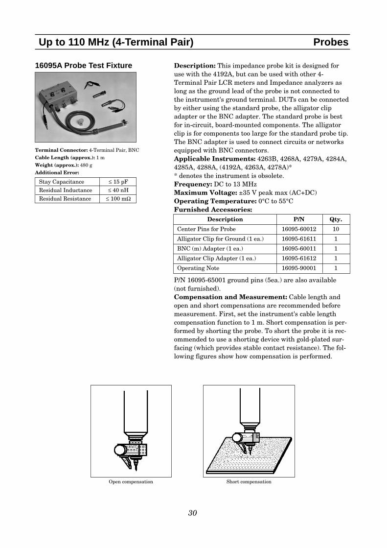
16095A Probe Test Fixture
Terminal Connector: 4-Terminal Pair, BNC
Cable Length (approx.): 1 m
Weight (approx.): 480 g
Additional Error:
30
Up to 110 MHz (4-Terminal Pair) Probes
Description: This impedance probe kit is designed foruse with the 4192A, but can be used with other 4-Terminal Pair LCR meters and Impedance analyzers aslong as the ground lead of the probe is not connected tothe instrument's ground terminal. DUTs can be connectedby either using the standard probe, the alligator clipadapter or the BNC adapter. The standard probe is bestfor in-circuit, board-mounted components. The alligatorclip is for components too large for the standard probe tip.The BNC adapter is used to connect circuits or networksequipped with BNC connectors.Applicable Instruments: 4263B, 4268A, 4279A, 4284A,4285A, 4288A, (4192A, 4263A, 4278A)** denotes the instrument is obsolete.Frequency: DC to 13 MHzMaximum Voltage: ±35 V peak max (AC+DC)Operating Temperature: 0°C to 55°CFurnished Accessories:
P/N 16095-65001 ground pins (5ea.) are also available(not furnished).Compensation and Measurement: Cable length andopen and short compensations are recommended beforemeasurement. First, set the instrument's cable lengthcompensation function to 1 m. Short compensation is per-formed by shorting the probe. To short the probe it is rec-ommended to use a shorting device with gold-plated sur-facing (which provides stable contact resistance). The fol-lowing figures show how compensation is performed.
Description P/N Qty.
Center Pins for Probe 16095-60012 10
Alligator Clip for Ground (1 ea.) 16095-61611 1
BNC (m) Adapter (1 ea.) 16095-60011 1
Alligator Clip Adapter (1 ea.) 16095-61612 1
Operating Note 16095-90001 1
Open compensation Short compensation
Stay Capacitance ≤ 15 pFResidual Inductance ≤ 40 nHResidual Resistance ≤ 100 mΩ
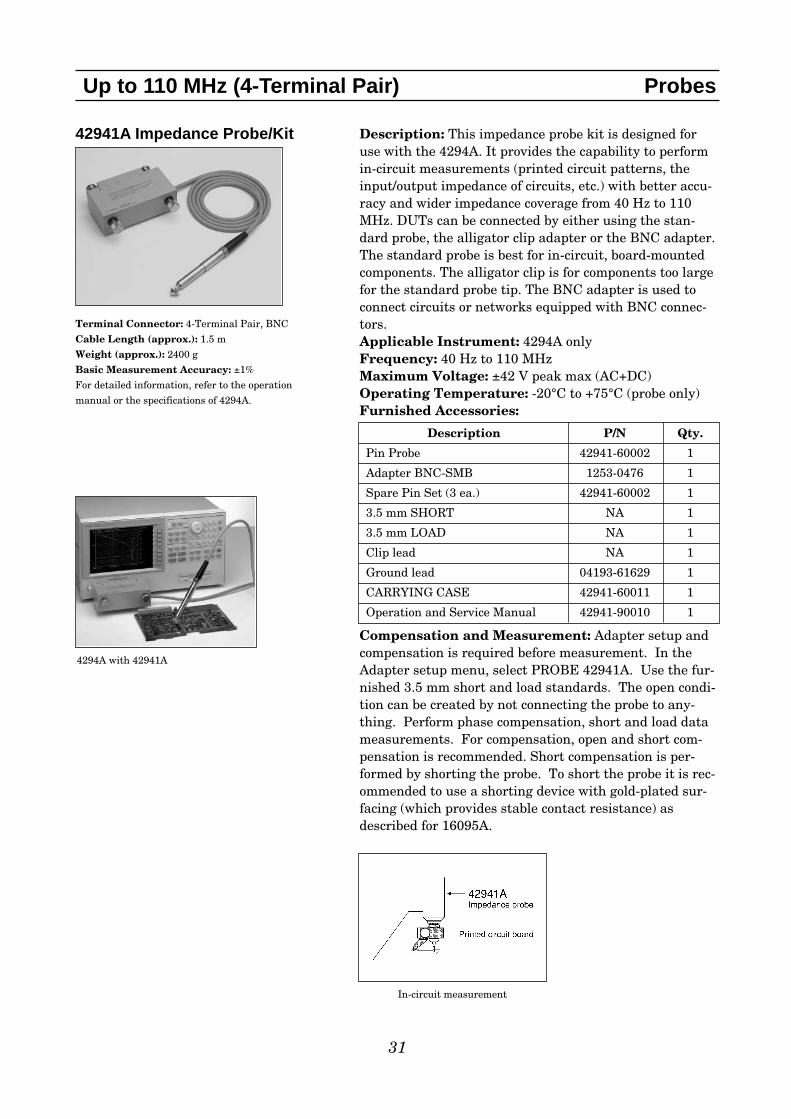
42941A Impedance Probe/Kit
Terminal Connector: 4-Terminal Pair, BNC
Cable Length (approx.): 1.5 m
Weight (approx.): 2400 g
Basic Measurement Accuracy: ±1%
For detailed information, refer to the operation
manual or the specifications of 4294A.
31
Up to 110 MHz (4-Terminal Pair) Probes
Description: This impedance probe kit is designed foruse with the 4294A. It provides the capability to performin-circuit measurements (printed circuit patterns, theinput/output impedance of circuits, etc.) with better accu-racy and wider impedance coverage from 40 Hz to 110MHz. DUTs can be connected by either using the stan-dard probe, the alligator clip adapter or the BNC adapter.The standard probe is best for in-circuit, board-mountedcomponents. The alligator clip is for components too largefor the standard probe tip. The BNC adapter is used toconnect circuits or networks equipped with BNC connec-tors.Applicable Instrument: 4294A onlyFrequency: 40 Hz to 110 MHzMaximum Voltage: ±42 V peak max (AC+DC)Operating Temperature: -20°C to +75°C (probe only)Furnished Accessories:
Compensation and Measurement: Adapter setup andcompensation is required before measurement. In theAdapter setup menu, select PROBE 42941A. Use the fur-nished 3.5 mm short and load standards. The open condi-tion can be created by not connecting the probe to any-thing. Perform phase compensation, short and load datameasurements. For compensation, open and short com-pensation is recommended. Short compensation is per-formed by shorting the probe. To short the probe it is rec-ommended to use a shorting device with gold-plated sur-facing (which provides stable contact resistance) asdescribed for 16095A.
4294A with 42941A
Description P/N Qty.
Pin Probe 42941-60002 1
Adapter BNC-SMB 1253-0476 1
Spare Pin Set (3 ea.) 42941-60002 1
3.5 mm SHORT NA 1
3.5 mm LOAD NA 1
Clip lead NA 1
Ground lead 04193-61629 1
CARRYING CASE 42941-60011 1
Operation and Service Manual 42941-90010 1
In-circuit measurement

32
Up to 110 MHz (4-Terminal Pair) DC Bias Accessories
16065A 200Vdc External VoltageBias Fixture
Terminal Connector: 4-Terminal Pair, BNCDUT Connection: 4-TerminalExternal Bias Input connector: High Voltage BNC(f)Dimensions (approx.): 180(W) x 120(H) x 200(D) [mm]Cable Length (approx.): 40 cmWeight (approx.): 1500 g
High Voltage BNC(f) connector for external bias inputBNC(f) connector for voltage monitor output
LCR meter with 16065A
16065C 40Vdc External Voltage Bias Adapter
Terminal Connector: 4-Terminal Pair, BNCExternal Bias Input connector: BNC(f)Dimensions (approx.): 160(W) x 50(H) x 150(D) [mm]Cable Length (approx.): 210 mmWeight (approx.): 450 g
LCR meter with 16065C
Description: This test fixture makes it possible to mea-sure a DUT with up to ±200 V DC bias. The same mod-ules of 16047A/D can be used to allow measurements ofaxial/radial lead components.Applicable Instruments: 4263B, 4268A, 4279A, 4284A,4285A, 4288A, 4294A, (4192A, 4194A, 4263A, 4278A)** denotes the instrument is obsolete.Frequency: 50 Hz to 2 MHz Maximum Voltage: ±200 V peak max (AC+DC)Blocking Capacitor of 5.6 µF is connected in series withthe Hc terminal.Operating Temperature: 0°C to 55°CDUT Size: See the 16047A figure with module sizes.Furnished Accessories:
Compensation and Measurement: Open, short andload compensations are recommended before measure-ment. Short compensation is performed by shorting thecontacts of the test fixture with a shorting plate asdescribed for 16047A. Load compensation is performed byinserting a known standard device. After performingopen, short and load compensations, the DUT is connectedto the test fixture.
Description P/N Qty.
Module For Axial Lead 16061-70022 1
Module For Radial Lead mounting16061-70021 1
on fixture
Module For Short Radial Lead 16047-65001 1
Operating Note 16065-90010 1
Description: This adapter is designed to operate specifi-cally with the 4263B, 4268A and the 4288A. By connect-ing an external DC voltage source to this adapter, a biasvoltage of up to ±40 V can be supplied to a DUT. TheDUT can be inserted by connecting any direct attachment4-Terminal Pair test fixture to the adapter.Applicable Instruments: 4263A*/B, 4268A, 4278A*, 4288AFrequency: 50 Hz to 1 MHz Maximum Voltage: ±40 V peak max (AC+DC)Blocking Capacitor of 50 µF is connected in series withthe Hc terminal.Operating Temperature: 0°C to 55°CApplicable Fixtures: 16034E/G/H, 16044A, 16047A/D/E,16048A/B/D/E, 16089A/B/C/D/EFurnished Accessories:
Compensation and Measurement: Open and shortcompensations are recommended before measurement.Short compensation is performed by shorting the contactsof the test fixture that is in use. After performing openand short compensations, the DUT is connected to the testfixture.
Description P/N Qty.Operation and Service Manual 16065-90020 1
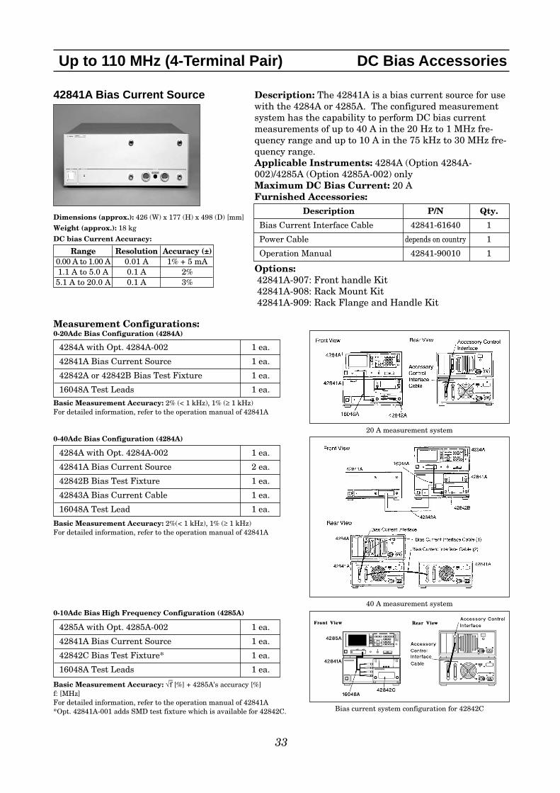
42841A Bias Current Source
Dimensions (approx.): 426 (W) x 177 (H) x 498 (D) [mm]
Weight (approx.): 18 kg
DC bias Current Accuracy:
Measurement Configurations:0-20Adc Bias Configuration (4284A)
Basic Measurement Accuracy: 2% (< 1 kHz), 1% (≥ 1 kHz)For detailed information, refer to the operation manual of 42841A
0-40Adc Bias Configuration (4284A)
Basic Measurement Accuracy: 2%(< 1 kHz), 1% (≥ 1 kHz)For detailed information, refer to the operation manual of 42841A
0-10Adc Bias High Frequency Configuration (4285A)
Basic Measurement Accuracy: √–f [%] + 4285A's accuracy [%]
f: [MHz]For detailed information, refer to the operation manual of 42841A*Opt. 42841A-001 adds SMD test fixture which is available for 42842C.
33
Up to 110 MHz (4-Terminal Pair) DC Bias Accessories
Description: The 42841A is a bias current source for usewith the 4284A or 4285A. The configured measurementsystem has the capability to perform DC bias currentmeasurements of up to 40 A in the 20 Hz to 1 MHz fre-quency range and up to 10 A in the 75 kHz to 30 MHz fre-quency range.Applicable Instruments: 4284A (Option 4284A-002)/4285A (Option 4285A-002) onlyMaximum DC Bias Current: 20 AFurnished Accessories:
Options:42841A-907: Front handle Kit42841A-908: Rack Mount Kit42841A-909: Rack Flange and Handle Kit
Description P/N Qty.
Bias Current Interface Cable 42841-61640 1
Power Cable depends on country 1
Operation Manual 42841-90010 1
4284A with Opt. 4284A-002 1 ea.
42841A Bias Current Source 1 ea.
42842A or 42842B Bias Test Fixture 1 ea.
16048A Test Leads 1 ea.
4284A with Opt. 4284A-002 1 ea.
42841A Bias Current Source 2 ea.
42842B Bias Test Fixture 1 ea.
42843A Bias Current Cable 1 ea.
16048A Test Lead 1 ea.
4285A with Opt. 4285A-002 1 ea.
42841A Bias Current Source 1 ea.
42842C Bias Test Fixture* 1 ea.
16048A Test Leads 1 ea.
Range Resolution Accuracy (±)0.00 A to 1.00 A 0.01 A 1% + 5 mA1.1 A to 5.0 A 0.1 A 2%5.1 A to 20.0 A 0.1 A 3%
20 A measurement system
40 A measurement system
Bias current system configuration for 42842C
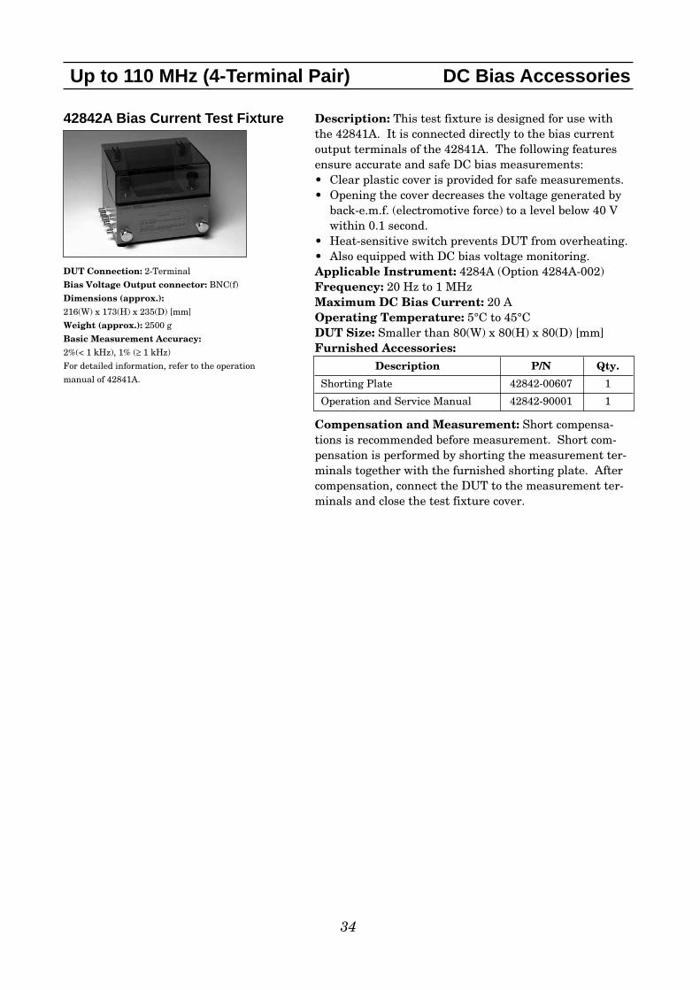
42842A Bias Current Test Fixture
DUT Connection: 2-Terminal
Bias Voltage Output connector: BNC(f)
Dimensions (approx.):216(W) x 173(H) x 235(D) [mm]
Weight (approx.): 2500 g
Basic Measurement Accuracy:2%(< 1 kHz), 1% (≥ 1 kHz)
For detailed information, refer to the operation
manual of 42841A.
34
Up to 110 MHz (4-Terminal Pair) DC Bias Accessories
Description: This test fixture is designed for use withthe 42841A. It is connected directly to the bias currentoutput terminals of the 42841A. The following featuresensure accurate and safe DC bias measurements:• Clear plastic cover is provided for safe measurements. • Opening the cover decreases the voltage generated by
back-e.m.f. (electromotive force) to a level below 40 Vwithin 0.1 second.
• Heat-sensitive switch prevents DUT from overheating. • Also equipped with DC bias voltage monitoring.Applicable Instrument: 4284A (Option 4284A-002)Frequency: 20 Hz to 1 MHzMaximum DC Bias Current: 20 AOperating Temperature: 5°C to 45°CDUT Size: Smaller than 80(W) x 80(H) x 80(D) [mm]Furnished Accessories:
Compensation and Measurement: Short compensa-tions is recommended before measurement. Short com-pensation is performed by shorting the measurement ter-minals together with the furnished shorting plate. Aftercompensation, connect the DUT to the measurement ter-minals and close the test fixture cover.
Description P/N Qty.
Shorting Plate 42842-00607 1
Operation and Service Manual 42842-90001 1

42842B Bias Current Test Fixture
DUT Connection: 2-Terminal
Bias Voltage Output connector: BNC(f)
Dimensions (approx.):237(W) x 173(H) x 235(D) [mm]
Weight (approx.): 3000 g
Basic Measurement Accuracy:2% (< 1 kHz), 1% (≥ 1 kHz)
For detailed information, refer to the operation
manual of 42841A.
35
Up to 110 MHz (4-Terminal Pair) DC Bias Accessories
Description: This test fixture is designed for use withthe 42841A. It is connected directly to the bias currentoutput terminals of the 42841A. The following featuresensure accurate and safe DC bias measurements:• Clear plastic cover is provided for safe measurements. • Opening the cover decreases the voltage generated by
back-e.m.f. (electromotive force) to a level below 40 Vwithin 0.1 second.
• Heat-sensitive switch prevents DUT from overheating. • Also equipped with DC bias voltage monitoring.Applicable Instrument: 4284A (Option 4284A-002)Frequency: 20 Hz to 1 MHzMaximum DC Bias Current: 40 AOperating Temperature: 5°C to 45°CDUT Size: Smaller than 80(W) x 80(H) x 80(D) [mm]Furnished Accessories:
Compensation and Measurement: Short compensa-tions is recommended before measurement. Short com-pensation is performed by shorting the measurement ter-minals together with the furnished shorting plate. Aftercompensation, connect the DUT to the measurement ter-minals and close the test fixture cover.
Description P/N Qty.
Protection Caps 1401-0240 2
Shorting Plate 42842-00607 1
Operation and Service Manual 42842-90001 1
36
Up to 110 MHz (4-Terminal Pair) DC Bias Accessories
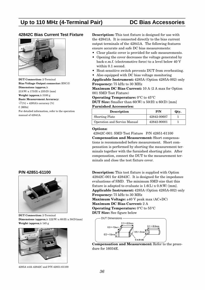
42842C Bias Current Test Fixture
DUT Connection: 2-Terminal
Bias Voltage Output connector: BNC(f)
Dimensions (approx.):213(W) x 173(H) x 235(D) [mm]
Weight (approx.): 3100 g
Basic Measurement Accuracy:√–f [%] + 4285A's accuracy [%]
f: [MHz]
For detailed information, refer to the operation
manual of 42841A.
P/N 42851-61100
DUT Connection: 2-Terminal
Dimensions (approx.): 122(W) x 60(H) x 58(D)[mm]
Weight (approx.): 145 g
4285A with 42842C and P/N 42851-61100
Description: This test fixture is designed for use withthe 42841A. It is connected directly to the bias currentoutput terminals of the 42841A. The following featuresensure accurate and safe DC bias measurements:• Clear plastic cover is provided for safe measurements. • Opening the cover decreases the voltage generated by
back-e.m.f. (electromotive force) to a level below 40 Vwithin 0.1 second.
• Heat-sensitive switch prevents DUT from overheating. • Also equipped with DC bias voltage monitoringApplicable Instrument: 4285A (Option 4285A-002) onlyFrequency: 75 kHz to 30 MHzMaximum DC Bias Current: 10 A (2 A max for Option001 SMD Test Fixture)Operating Temperature: 0°C to 45°CDUT Size: Smaller than 60(W) x 50(H) x 60(D) [mm]Furnished Accessories:
Options:42842C-001: SMD Test Fixture P/N 42851-61100Compensation and Measurement: Short compensa-tions is recommended before measurement. Short com-pensation is performed by shorting the measurement ter-minals together with the furnished shorting plate. Aftercompensation, connect the DUT to the measurement ter-minals and close the test fixture cover.
Description P/N Qty.
Shorting Plate 42842-00607 1
Operation and Service Manual 42842-90001 1
Description: This test fixture is supplied with Option42842C-001 for 42842C. It is designed for the impedanceevaluations of SMD. The minimum SMD size that thisfixture is adapted to evaluate is 1.6(L) x 0.8(W) [mm].Applicable Instrument: 4285A (Option 4285A-002) onlyFrequency: 75 kHz to 30 MHzMaximum Voltage: ±40 V peak max (AC+DC)Maximum DC Bias Current: 2 A Operating Temperature: 0°C to 55°CDUT Size: See figure below
Compensation and Measurement: Refer to the proce-dure for 16034E.
DUT Dimensions

42843A Bias Current Cable
Cable Length (approx.): 960 mm
Weight (approx.): 1200 g
37
Up to 110 MHz (4-Terminal Pair) DC Bias Accessories
Description: The 42843A is designed for use with42841A and 42842B, 40 A DC bias measurement configu-ration. It provides a shielded connection between 42841Aand 42842B.Applicable Instrument: 4284A (Option 4284A-002) Operating Temperature: 0°C to 55°CFurnished Accessories:
Description P/N Qty.
Operation and Service Manual 42842-90001 1

16451B Dielectric Test Fixture
Terminal Connector: 4-Terminal Pair, BNC
Dimension (approx.): See page 40
Cable Length (approx.):0.8 m(from connector to electrodes)
Weight (approx.): 3700 g
Measurement Accuracy (supplemental performance characteristics):
f: measured frequency [Hz] f≤ 30MHz
ε’rm: measured permittivity
tan δ: measured dissipation factor
ε0 : permittivity of air 8.854×10⁻¹²[F/m]
d: diameter of electrode A,B
t: thickness of material [mm]
Az: Impedance measurement error of instrument
Ad: D measurement error of instrument
The material is assumed to be ideally flat.
The above equation is applicable for electrodes A and
B when using the contacting electrode method.
38
Up to 110 MHz (4-Terminal Pair) Material
Description: The 16451B is used to evaluate the dielec-tric constant of solid dielectric materials accurately, andcomplies with ASTM D150. The 16451B employs the par-allel plate method, which sandwiches the materialbetween two electrodes to form a capacitor. LCR meter oran Impedance Analyzer is then used to measure thecapacitance created from the fixture. A measurementblock diagram of the parallel plate method is shownbelow:
Notice the stray capacitance, which is formed on the testmaterial as shown in the figure above. The guard elec-trode helps to eliminate the stray capacitance at the edgeof the electrode.
Basic Measurement Accuracy (including the 4294A):
Parallel plate method
Typical Permittivity (ε r') Measurement Accuracy:
4294A with 16451B
Typical Loss Tangent (tan δ) Measurement Accuracy:
ε'r accuracy ( )ε' r m
∆ε' r m
AZ + 0.04 f 2 ε'rm ε0 +π 2
d
t
2
100 (ε'rm – 1)
(ε'rm – )t0.01
[%]
π 2d
t
2
Ea = 0.005 + 0.0004 f2 ε'rm ε0
Eb =100
tan δε'r m
∆ε'r m
tan δ < 0.1 :
ε * Loss Tangent Accuracy (∆ tan δ)tan δ < 0.1 : Ad + Ea + Eb
4294A Measurement Settings;
1. Osc level : 500 mV
2. BW: 5
3. Adapter setup : 1 m
4. Compensation : Open, short and load

Applicable Instruments: 4263B, 4268A, 4279A, 4284A, 4285A, 4288A, 4294A, (4192A, 4194A, 4263A,4278A)** denotes the instrument is obsolete.
Frequency: ≤ 30 MHzMaximum Voltage: ±42 V peak max. (AC+DC) Operating Temperature: 0°C to 55°C
Material Size:
39
Up to 110 MHz (4-Terminal Pair) Material
Electrodes for contacting electrode method
(Rigid Metal Electrode) Material size for electrode-A Material size for electrode-B
Electrodes for contacting electrode method
(Thin Film Electrode)
Material size for electrode-C Material size for electrode-D
Electrode Type Diameter of MUT Thickness of MUT Diameter of Electrode Max. Frequency
A 40 mm ~ 56 mm t ≤ 10 mm 38 mm 30 MHz
B 10 mm ~ 56 mm t ≤ 10 mm 5 mm 30 MHz
Electrode Type Diameter of MUT Thickness of MUT Diameter of Electrode* Max. Frequency
C 56 mm t ≤ 10 mm 5 ~ 50 mm 30 MHz
D 20 mm ~ 56 mm t ≤ 10 mm 5 ~ 14 mm 30 MHz
Equipped with Electrodes A and B for flat and smooth materials.
Equipped with Electrodes C and D for rough or extremely thin materials.
* diameter of applied thin film electrode

Furnished Accessories:
40
Up to 110 MHz (4-Terminal Pair) Material
Dimensions of unguarded electrode Dimensions of fixture assembly
Description P/N Qty.
Test Fixture including Electrode-A, unguarded electrode and cover 16451-61001 1 A
Electrode-B and cover 16451-60013 1 B
Electrode-C and cover 16451-60012 1 C
Electrode-D and cover 16451-60014 1 D
Attachment for error compensation and cover 16451-60021 1 E
Hex key (for replacing electrodes) 8710-1181 1 F
Carrying Case 16451-60001 1 G

Compensation and Measurement: There are three measurement methods for the 16451B. They arethe Contacting Electrode Method (used with 16451B's rigid metal electrode, without any electrodes onthe material under test), the Contacting Electrode Method (used with thin film electrodes made on thematerial under test), and the Non-Contacting Electrode (Air Gap method). Select the suitable measure-ment method and the suitable electrode for the material under test according to the following table.
Summary of Measurement Method
Open and short compensations are recommended in combination with the cable length compensationbefore measurement. When measuring above 5 MHz with the 4285A or the 4294A*, load compensationis also recommended. First, set the instrument's cable length compensation function to 1 m. Then, openand short compensation is performed by using the furnished electrode attachment. Load compensationis performed, by preparing a working standard. After performing open, short and load compensations,the MUT is sandwiched by the parallel electrodes and the capacitance is measured. Relative permittivi-ty is calculated from the measured capacitance in the following manner:
ta × Cpεr'= ———————dπ × (—)2 × εo2εr' : Relative permittivity
Cp : Capacitance (measurement data)
εo : 8.854 × 10⁻¹² [F/m]
ta : Average thickness of test material
d : Diameter of guarded electrode
*For more information on load compensation with the 4294A, see section 13 of the 4294A programmingmanual.
Up to 110 MHz (4-Terminal Pair) Material
41
Measurement Contacting Electrode Method Contacting Electrode Method Non-contacting Electrode Method (used with Rigid metal (used with thin film electrode) Method
electrode)
Accuracy Low ············································································································································→ High
Operation Simple··································································································································→ Complex
Applicable Thick, solid and smooth Materials on which thin film Thick, and soft materials. Materials materials can be applied without Rough materials also.
changing its characteristics

42
16452A Liquid Dielectric Test Fixture
Terminal Connector: 4-Terminal Pair, SMA
Dimensions (approx.): 85(H) x 85(W) x 37(D) [mm]
Weight (approx.): 1400 g
Measurement Accuracy: A + B + C [%]
Up to 110 MHz (4-Terminal Pair) Material
Description: This test fixture provides accurate dielectric con-stant and impedance measurements of liquid materials. The16452A employs the parallel plate method, which sandwichesthe liquid material between two electrodes to form a capacitor.A LCR meter or an impedance analyzer is then used to measurethe capacitance created from the fixture.Applicable Instruments: 4284A, 4285A, 4294A, (4194A)** denotes the instrument is obsolete.Frequency: 20 Hz to 30 MHzOperating Temperature: –20°C to 125°CMaximum Voltage: ±42 V peak max. (AC+DC)Material Capacity: Required sample liquid capacity dependson the gap of the electrodes.
Furnished Accessories:
Requires the following interface cables to connect to a measure-ment instrument. Select accordingly to the required tempera-ture conditions.
Gap of electrodes 0.3 mm 0.5 mm 1 mm 2 mmAir Capacitance 34.9 pF 21.2 pF 10.9 pF 5.5 pF
±25% ±15% ±10% ±10%Sample liquid capacity 3.4 ml 3.8 ml 4.8 ml 6.8 mlApplicable Frequency 20 Hz – 30 MHz
Description P/N Qty.Shorting Plate 16092-08010 1 EO-ring for Liquid Outlet 0905-1277 1 DSpacer (1.3 mm thickness) 16452-00601 1 FSpacer (1.5 mm thickness) 16452-00602 1 FSpacer (2.0 mm thickness) 16452-00603 1 FSpacer (3.0 mm thickness) 16452-00604 1 FLid of Liquid Outlet 16452-24002 1 GSMA-BNC Adapter 1250-1200 4 HWaterproof Cap for BNC Connector 1252-5831 4 ICarrying Case 16452-60101 1 –Operation and Service Manual 16452-90000 1 –Angle Iron of Stand Body for Fixture Stand 16452-01201 2 –Screw of Stand Body for Fixture Stand 0515-0914 4 CScrew for Fixture Stand 0515-0914 4 –Electrode (High and Low) NA 2 A,B
Electrode gap (mm) A (%)0.3 0.005 × M.R.P0.5 0.006 × M.R.P1.0 0.008 × M.R.P2.0 0.020 × M.R.P
Temperature Model# or P/NCable Length
(approx.)0°C to 55°C 16048A 0.94 m
–20°C to 125°C 16452-61601 1 m–20°C to 150°C 16048G for 4294A only 1 m
M.R.P is Measurement Relative Permittivity
Error B [%]
Error C [%] = Measurement Error of Instrument
4284A with 16452A
(A)
(H)
(B)
(I)
(C)
(F)
(E)
(D)
(G)

Up to 110 MHz (4-Terminal Pair) Material
43
Compensation and Measurement: Open (Air-Capacitance)and short compensations are recommended in combination withthe cable length compensation before measurement. First, setthe instrument's cable length compensation function to 1 m.Then, short compensation is performed by using the furnishedshorting plate. Open compensation is not performed, but its val-ues are used in the dielectric constant equation as shown below:
Cp 1εr =α (—— – j ———— )Co ω CoRpα: : Correction coefficientεr: Relative dielectric constantCp : Liquid capacitance (measurement data)Co : Air capacitance (measurement data) or open compensation dataRp: Equivalent parallel resistance (measurement data)ω: Angular frequency (ω=2πf)
The following figures below show how compensation and mea-surement is performed.
Note: the 16452A is not capable of measuring salt or ionic solu-tions or other liquids with bulk conductivity due to the electrodepolarization phenomenon.
Test fixture overview
Short compensation
Method of connection
Pouring the liquid into the fixture
Fixture materialsElectrode:Ni plated Cobal
(Fe 54%, Co 17%, Ni 29%)Insulator: Alumina (Al2O3)O-ring: Viton (Fluro rubber)

44
This page intentionally left blank.

45
Test Fixtures (7 mm connector) for Impedance Measurements up to 3 GHz
Up to 3 GHz (7 mm)
Frequency RangeDC 1k 1M 10M 100M 1G [Hz] 2G [Hz] 3G [Hz]
16092A 500M16093A 250M16093B 125M16191A 2G16192A 2G16193A 2G16194A 2G16196A/B/C/D 3G16197A 3G16094A 125M16200B 1M 1G16453A 1M 1G16454A 1k 1G
: When 16085B is used.
: When 42942A is used.
Frequency Up to 110 MHz Up to 3 GHzRange (Terminal Configuration: 4-Terminal Pair) (Terminal Configuration: 7 mm)
Measurement 4192A, 4194A, 4263A/B, 4268A, 4291A/B, 4294A + 42942A, 4395A Instruments 4278A, 4279A, 4284A, 4285A, 4288A, w/Opt.010 + 43961A, 4396A/B w/Opt.010
4294A + 43961A, 4286A, 4287A, E4991AAny 4TP instruments (excluding 4294A) +16085B
Frequency DC (High Resistance Measurement) 1 kHz (Milliohm Measurement)
Measurement 4339A/B, 4349A/B 4338A/BInstruments
Applicable Instrument
46
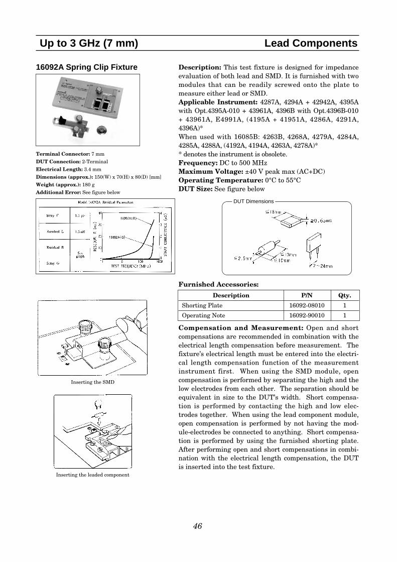
16092A Spring Clip Fixture
Terminal Connector: 7 mm
DUT Connection: 2-Terminal
Electrical Length: 3.4 mm
Dimensions (approx.): 150(W) x 70(H) x 80(D) [mm]
Weight (approx.): 180 g
Additional Error: See figure below
Up to 3 GHz (7 mm) Lead Components
Description: This test fixture is designed for impedanceevaluation of both lead and SMD. It is furnished with twomodules that can be readily screwed onto the plate tomeasure either lead or SMD.Applicable Instrument: 4287A, 4294A + 42942A, 4395Awith Opt.4395A-010 + 43961A, 4396B with Opt.4396B-010+ 43961A, E4991A, (4195A + 41951A, 4286A, 4291A,4396A)*When used with 16085B: 4263B, 4268A, 4279A, 4284A,4285A, 4288A, (4192A, 4194A, 4263A, 4278A)** denotes the instrument is obsolete.Frequency: DC to 500 MHzMaximum Voltage: ±40 V peak max (AC+DC)Operating Temperature: 0°C to 55°CDUT Size: See figure below
Furnished Accessories:
Compensation and Measurement: Open and shortcompensations are recommended in combination with theelectrical length compensation before measurement. Thefixture’s electrical length must be entered into the electri-cal length compensation function of the measurementinstrument first. When using the SMD module, opencompensation is performed by separating the high and thelow electrodes from each other. The separation should beequivalent in size to the DUT’s width. Short compensa-tion is performed by contacting the high and low elec-trodes together. When using the lead component module,open compensation is performed by not having the mod-ule-electrodes be connected to anything. Short compensa-tion is performed by using the furnished shorting plate.After performing open and short compensations in combi-nation with the electrical length compensation, the DUTis inserted into the test fixture.
Description P/N Qty.
Shorting Plate 16092-08010 1
Operating Note 16092-90010 1
Inserting the SMD
Inserting the leaded component
DUT Dimensions

47
16093A Binding Post Test Fixture
Terminal Connector: 7 mm
DUT Connection: 2-Terminal
Electrical Length: 3.4 mm
Dimensions (approx.): 150(W) x 70(H) x 80(D) [mm]
Weight (approx.): 135 g
Additional Error: See figure below
Up to 3 GHz (7 mm) Lead Components
Description: This test fixture is designed for impedanceevaluation of axial/radial lead type devices. Two bindingposts separated by an interval of 7 mm ensure optimumcontact of lead components.Applicable Instrument: 4287A, 4294A + 42942A, 4395Awith Opt.4395A-010 + 43961A, 4396B with Opt.4396B-010+ 43961A, E4991A, (4195A + 41951A, 4286A, 4291A,4396A)*When used with 16085B: 4263B, 4268A, 4279A, 4284A,4285A, 4288A, (4192A, 4194A, 4263A, 4278A)** denotes the instrument is obsolete.Frequency: DC to 250 MHzMaximum Voltage: ±40 V peak max (AC+DC)Operating Temperature: 0°C to 55°CDUT Size: See figure below
Furnished Accessories:
Compensation and Measurement: Open and shortcompensations are recommended in combination with theelectrical length compensation before measurement. Thefixture’s electrical length must be entered into the electri-cal length compensation function of the measurementinstrument first. Open compensation is performed by nothaving the binding posts be connected to anything. Shortcompensation is performed by using the furnished short-ing plate. After performing open and short compensationsin combination with the electrical length compensation,the DUT is inserted into the test fixture.
Description P/N Qty.
Shorting Plate 16092-08010 1
Operating Note 16093-90001 1
Post spacing
* Obsoleted measurement configuration
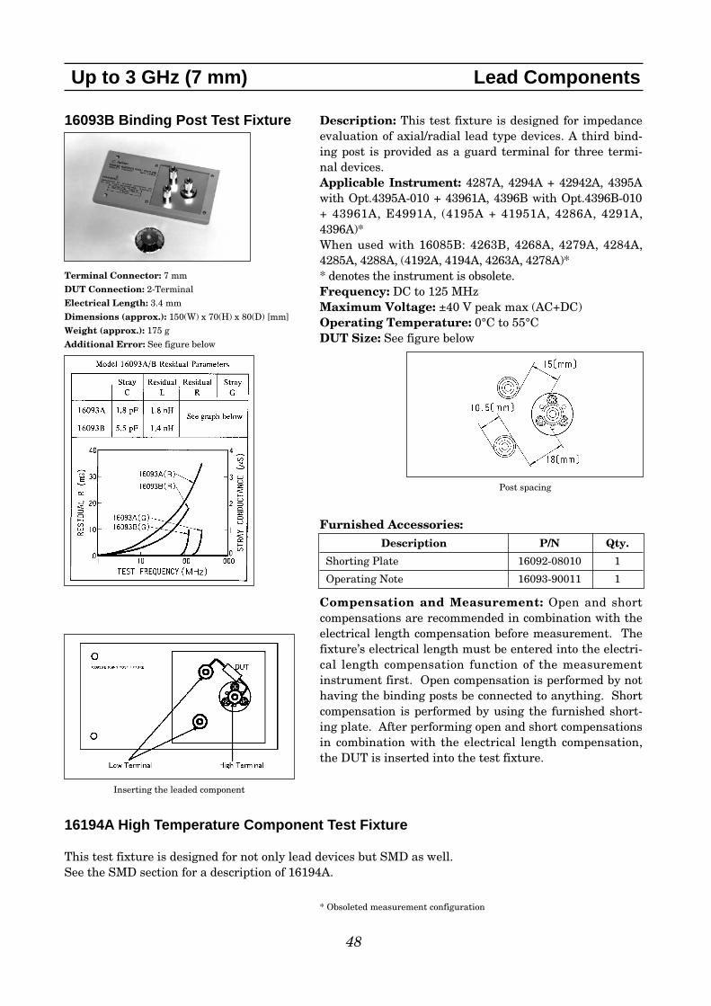
48
16093B Binding Post Test Fixture
Terminal Connector: 7 mm
DUT Connection: 2-Terminal
Electrical Length: 3.4 mm
Dimensions (approx.): 150(W) x 70(H) x 80(D) [mm]
Weight (approx.): 175 g
Additional Error: See figure below
16194A High Temperature Component Test Fixture
This test fixture is designed for not only lead devices but SMD as well.See the SMD section for a description of 16194A.
Up to 3 GHz (7 mm) Lead Components
Description: This test fixture is designed for impedanceevaluation of axial/radial lead type devices. A third bind-ing post is provided as a guard terminal for three termi-nal devices.Applicable Instrument: 4287A, 4294A + 42942A, 4395Awith Opt.4395A-010 + 43961A, 4396B with Opt.4396B-010+ 43961A, E4991A, (4195A + 41951A, 4286A, 4291A,4396A)*When used with 16085B: 4263B, 4268A, 4279A, 4284A,4285A, 4288A, (4192A, 4194A, 4263A, 4278A)** denotes the instrument is obsolete.Frequency: DC to 125 MHzMaximum Voltage: ±40 V peak max (AC+DC)Operating Temperature: 0°C to 55°CDUT Size: See figure below
Furnished Accessories:
Compensation and Measurement: Open and shortcompensations are recommended in combination with theelectrical length compensation before measurement. Thefixture’s electrical length must be entered into the electri-cal length compensation function of the measurementinstrument first. Open compensation is performed by nothaving the binding posts be connected to anything. Shortcompensation is performed by using the furnished short-ing plate. After performing open and short compensationsin combination with the electrical length compensation,the DUT is inserted into the test fixture.
Description P/N Qty.
Shorting Plate 16092-08010 1
Operating Note 16093-90011 1
Inserting the leaded component
Post spacing
* Obsoleted measurement configuration

49
16191A Side Electrode SMD Test Fixture
Terminal Connector: 7 mm
DUT Connection: 2-Terminal
Electrical Length: 14 mm
Dimensions (approx.): 150(W) x 70(H) x 110(D) [mm]
Weight (approx.): 500 g
Additional Error:
f: [GHz]
Up to 3 GHz (7 mm) SMD
Description: This test fixture is designed for impedanceevaluations of side electrode SMD. The minimum SMDsize that this fixture is adapted to evaluate is 2 (L) [mm].Applicable Instrument: 4287A, 4294A + 42942A, 4395Awith Opt.4395A-010 + 43961A, 4396B with Opt.4396B-010+ 43961A, E4991A, (4195A + 41951A, 4286A, 4291A,4396A)*When used with 16085B: 4263B, 4268A, 4279A, 4284A,4285A, 4288A, (4192A, 4194A, 4263A, 4278A)** denotes the instrument is obsolete.Frequency: DC to 2 GHz Maximum Voltage: ±40 V peak max (AC +DC) Operating Temperature: -55°C to +85°CDUT size: 2.0 to 12 mm (length)
Furnished Accessories:
Type of Error Impedance
Proportional Error 1.5 x f2 [%]
Open Repeatability 2 + 30 x f [µS]
Short Repeatability 30 + 250 x f [mΩ]
DUT Dimensions
Description P/N Qty. Option
Wrench 8710-1181 1 Standard
Operation and Service Manual 16191-90010 1 Standard
General SizedShorting Device 16191-29001 1 16191A-701(1 × 1 × 2.4 (mm))Shorting Device 16191-29002 1 16191A-701(1.6 × 2.4 × 2 (mm))Shorting Device 16191-29003 1 16191A-701(2.4 × 2.4 × 3.2 (mm))Shorting Device 16191-29004 1 16191A-701(2.4 × 2.4 × 4.5 (mm))
EIA/EIAJ Industrial Standard SizedShorting Device 16191-29005 1 16191A-010(1 × 0.5 × 0.5 (mm))Shorting Device 16191-29006 1 16191A-010(1.6 × 0.8 × 0.8 (mm))Shorting Device 16191-29007 1 16191A-010(2.0 × 1.2 × 0.8 (mm))Shorting Device 16191-29008 1 16191A-010(3.2 × 1.6 × 0.8 (mm))
Case for Shorting Devices 1540-0692 1 16191A-010/701
Magnifying Lens 16193-60002 1 16191A-710
Tweezers 8710-2081 1 16191A-710

50
Up to 3 GHz (7 mm) SMD
Options:16191A-010: Add EIA/EIAJ industrial standard sizedshorting bar set16191A-701: Add general sized shorting bar set16191A-710: Add the magnifying lens and tweezers
Compensation and Measurement: Open and shortcompensations are recommended in combination with theelectrical length compensation before measurement. Thefixture’s electrical length must be entered into the electri-cal length compensation function of the measurementinstrument first. Then open compensation is performedby separating the high and the low electrodes from eachother. The separation should be equivalent in size to theDUT’s width. Short compensation is performed by usingoption 16191A-010/701 shorting bar set. After performingopen and short compensations in combination with theelectrical length compensation, the DUT is inserted intothe test fixture. The following figures show how measure-ment is performed.
Test fixture overview
Positioning the device
a) Set the device within the devicescale and adjust the positioner.
b) Place the device on the electrode.c) Adjust the horizontal positioning
knob and tighten the horizontallocking knob.
d) Latch off the pressure arm and turndown the arm. Measure the device.

51
16192A Parallel Electrode SMD Test Fixture
Terminal Connector: 7 mm
DUT Connection: 2-Terminal
Electrical Length: 11 mm
Dimensions (approx.): 150(W) x 70(H) x 90(D) [mm]
Weight (approx.): 400 g
Additional Error:
f: [GHz]
Up to 3 GHz (7 mm) SMD
Description: This test fixture is designed for impedanceevaluations of parallel electrode SMD. The minimumSMD size that this fixture is adapted to evaluate is 1 (L)[mm].Applicable Instrument: 4287A, 4294A + 42942A, 4395Awith Opt.4395A-010 + 43961A, 4396B with Opt.4396B-010+ 43961A, E4991A, (4195A + 41951A, 4286A, 4291A,4396A)*When used with 16085B: 4263B, 4268A, 4279A, 4284A,4285A, 4288A, (4192A, 4194A, 4263A, 4278A)** denotes the instrument is obsolete.Frequency: DC to 2 GHz Maximum Voltage: ±40 V peak max (AC+DC)Operating Temperature: -55°C to +85°CDUT size: 1 mm to 20 mm (length)
Furnished Accessories:
Type of Error Impedance
Proportional Error 1.5 x f2 [%]
Open Repeatability 2 + 30 x f [µS]
Short Repeatability 30 + 250 x f [mΩ]
DUT Dimensions
Description P/N Qty. Option
Wrench 8710-1181 1 Standard
Operation and Service Manual 16192-90010 1 Standard
General SizedShorting Device 16191-29001 1 16192A-701(1 × 1 × 2.4 (mm))Shorting Device 16191-29002 1 16192A-701(1.6 × 2.4 × 2 (mm))Shorting Device 16191-29003 1 16192A-701(2.4 × 2.4 × 3.2 (mm))Shorting Device 16191-29004 1 16192A-701(2.4 × 2.4 × 4.5 (mm))
EIA/EIAJ Industrial Standard SizedShorting Device 16191-29005 1 16192A-010(1 × 0.5 × 0.5 (mm))Shorting Device 16191-29006 1 16192A-010(1.6 × 0.8 × 0.8 (mm))Shorting Device 16191-29007 1 16192A-010(2.0 × 1.2 × 0.8 (mm))Shorting Device 16191-29008 1 16192A-010(3.2 × 1.6 × 0.8 (mm))
Case for Shorting Devices 1540-0692 1 16192A-010/701
Magnifying Lens 16193-60002 1 16192A-710
Tweezers 8710-2081 1 16192A-710

52
Up to 3 GHz (7 mm) SMD
Options:16192A-010: Add EIA/EIAJ industrial standard sizedshorting bar set16192A-701: Add general sized shorting bar set16192A-710: Add the magnifying lens and tweezers Compensation and Measurement: Open and shortcompensations are recommended in combination with theelectrical length compensation before measurement. Thefixture’s electrical length must be entered into the electri-cal length compensation function of the measurementinstrument first. Then open compensation is performedby separating the high and the low electrodes from eachother. The separation should be equivalent in size to theDUT’s width. Short compensation is performed by usingoption 16192A-010/701 shorting bar set. After performingopen and short compensations in combination with theelectrical length compensation, the DUT is inserted intothe test fixture. The following figures show how compen-sation and measurement is performed.
Test fixture overview
Electrodes configuration and SMD size

16194A High Temperature Component Test Fixture
Terminal Connector: 7 mm
DUT Connection: 2-Terminal
Electrical Length: 50 mm
Dimensions (approx.): 150(W) x 40(H) x 80(D) [mm]
Weight (approx.): 350 g
Additional Error:SMD:
Leaded device:
f: [GHz]
53
Up to 3 GHz (7 mm) SMD
Description: This test fixture is designed for measuringboth axial/radial leaded devices and SMD within the tem-perature range from –55 to +200°C (recommended to beused with 4291A/B’s high temperature test head).Applicable Instrument: 4287A, 4294A + 42942A, 4395Awith Opt.4395A-010 + 43961A, 4396B with Opt.4396B-010+ 43961A, E4991A, (4195A + 41951A, 4286A, 4291A,4396A)*When used with 16085B: 4263B, 4268A, 4279A, 4284A,4285A, 4288A, (4192A, 4194A, 4263A, 4278A)** denotes the instrument is obsolete.Frequency: DC to 500 MHz (with open and short com-
pensation)DC to 2 GHz (with open and short and loadcompensation)
Maximum Voltage: ±40 V peak max (AC +DC)Operating Temperature: -55°C to +200°CDUT size: See figure below.Furnished Accessories:Type of Error Impedance
Proportional Error 20 x f2 [%]
Open Repeatability 80 + 250 x f [µS]
Short Repeatability 0.2 + 2.5 x f [Ω]
Type of Error Impedance
Proportional Error 20 x f2 [%]
Open Repeatability 80 + 250 x f [µS]
Short Repeatability 0.4 + 12.5 x f [Ω]
DUT Dimensions
Description P/N Qty. Option
Wrench 8710-1181 1 Standard
Tweezers 8710-2081 1 Standard
50Ω SMD Resistor NA 10 Standard
Operation and Service Manual 16194-90010 1 Standard
General SizedShorting Device 16191-29001 1 16194A-701(1 × 1 × 2.4 (mm))Shorting Device 16191-29002 1 16194A-701(1.6 × 2.4 × 2 (mm))Shorting Device 16191-29003 1 16194A-701(2.4 × 2.4 × 3.2 (mm))Shorting Device 16191-29004 1 16194A-701(2.4 × 2.4 × 4.5 (mm))
EIA/EIAJ Industrial Standard SizedShorting Device 16191-29005 1 16194A-010(1 × 0.5 × 0.5 (mm))Shorting Device 16191-29006 1 16194A-010(1.6 × 0.8 × 0.8 (mm))Shorting Device 16191-29007 1 16194A-010(2.0 × 1.2 × 0.8 (mm))Shorting Device 16191-29008 1 16194A-010(3.2 × 1.6 × 0.8 (mm))
Case for Shorting Devices 1540-0692 1 16194A-010/701

54
Up to 3 GHz (7 mm) SMD
Options:16194A-010: Add EIA/EIAJ industrial standard sizedshorting bar set16194A-701: Add general sized shorting bar setCompensation and Measurement: Before beginningthe measurement, the appropriate device holder (for aSMD or lead component) must be prepared with the textfixture. The following figure shows how the device holderis exchanged to match the device type.
The next step is to perform open and short compensationsin combination with the electrical length compensation.When measuring above 500 MHz, load copensation is alsorecommended. The fixture’s electrical length must beentered into the electrical length compensation function ofthe measurement instrument first. Then open compensa-tion is performed by separating the high and the low elec-trodes from each other. The separation should be equiva-lent in size to the DUT’s width. Short compensation isperformed by using the option 16194A-010/701 shortingbar set. Load compensation is performed by using thefurnished 50 Ω SMD chip resistor. After performing open,short, and load compensations in combination with theelectrical length compensation, the DUT is inserted intothe test fixture. The following figures show how measure-ment is performed.
Exchanging the device holder
1. Remove the ground plate2. When measuring SMD, attach
the knob on the device holder.3. Select the device holder suitable
for the device type. Loosen itsknob and insert into the arm.
4. Set the ground plate.
Placing the device

55
16196A Parallel Electrode SMD TestFixture
Terminal Connector: 7 mm
DUT Connection: 2-Terminal
Electrical Length: 26.2 mm
Dimensions (approx.): 140(W) x 48(H) x 78(D) [mm]
Weight (approx.): 250 g
Additional Error:
f: frequency [GHz]
4287A with 16196A
Fixture overview
Up to 3 GHz (7 mm) SMD
Description: This test fixture is designed for impedanceevaluations of parallel electrode SMDs. It achieves stablefrequency characteristics up to 3 GHz and provides highlyrepeatable measurements. The applicable SMD size codeis 0603 (inch)/1608 (mm).Applicable Instrument: 4287A, 4294A + 42942A, 4395Awith Opt.4395A-010 + 43961A, 4396B with Opt.4396B-010 +43961A, E4991A, (4195A + 41951A, 4286A, 4291A, 4396A)*When used with 16085B: 4263B, 4268A, 4279A, 4284A,4285A, 4288A, (4192A, 4194A, 4263A, 4278A)** denotes the instrument is obsolete.Frequency: dc to 3 GHzMaximum Voltage: ±40 V peak max (AC +DC)Operating Temperature: -55°C to +85°CDUT size: The applicable SMD size is 0603 (inch)/1608(mm). For details, see the figure below.
The 16196A is furnished with three different insulatorassemblies, since any gaps between the DUT and thecylindrical insulator will result in improper positioningand subsequent measurement errors. Select an insulatorassembly that reduces the gap the most. See the tablebelow for dimensions of the insulator assemblies.
Furnished Accessories:
Type of Error Impedance
Proportional Error 1.0 x f2 [%]
Open Repeatability 5 + 40 x f [µS]
Short Repeatability 30 + 125 x f [mΩ]
DUT Dimensions
Hole Diameter of Insulator SMD case size examplesassembly (mm) Length,Width, Height (mm)
φ 1.34 1.6 x 0.8 x 0.8
16196A φ 1.14 1.6 x 0.8 x 0.6
φ 1.08 1.6 x 0.8 x 0.5
Description P/N Qty.
Operation and Service Manual 16196-90040 1
Insulator Assembly φ 1.34 mm 16196-60112 1
Insulator Assembly φ 1.14 mm 16196-60113 1
Insulator Assembly φ 1.08 mm 16196-60114 1
Open Plate 16196-29002 1
Short Plate 16196-29026 1
Push Ring 16196-24004 1
Magnifying Lens1 16193-60002 1
Tweezers1 8710-2081 1
Wrench 8710-0909 1
Cleaning Rod 5182-7586 1
Carrying Case 16196-60150 1
1: Opt. 16196A-710 only

56
Up to 3 GHz (7 mm) SMD
Options:16196A-710 : Add the magnifying lens and tweezers
To maintain adequate measurement performance, keepthe electrodes and the short plate in good condition.Contaminants and abrasion on these parts considerablyaffect measurement results, especially for low value mea-surements. Periodic fixture cleaning and part replace-ment is recommended to avoid deterioration of measure-ment performance. The 16196x fixtures are designed withsimplicity in mind, so that an operator can easily replaceparts. Spare parts, which are likely to be abraded, aresupplied with the 16196U Maintenance Kit.
16196U Maintenance KitOpt. 16196U-010: Upper electrode, 5 piece set (commonto 16196A/B/C models)Opt. 16196U-100: Short plate for 0603 (inch)/1608 (mm)size, 5 piece set (for 16196A)Opt. 16196U-110: Lower electrode, 5 piece set (for16196A)
Compensation and Measurement: First of all, installthe appropriate insulator assembly into the fixture. Then,perform compensation. Open and short compensations arerecommended in combination with the electrical lengthcompensation before measurement. The fixture’s electri-cal length must be entered into the electrical length com-pensation function of the measurement instrument first.Next, open compensation is performed by placing the fur-nished open plate on top of the insulator assembly. Shortcompensation is performed by placing the furnished short-ing plate on top of the insulator assembly. After perform-ing open and short compensations in combination withthe electrical length compensation, the DUT is insertedinto the test fixture. Once the measurement of the DUT iscomplete, remove the DUT from the fixture, by using thefurnished push ring. The following figures show how com-pensation and measurement is performed.

57
Up to 3 GHz (7 mm) SMD
Short Compensation
DUT Measurement
Removing a DUT
Open Compensation
Compensation and Measurement continued
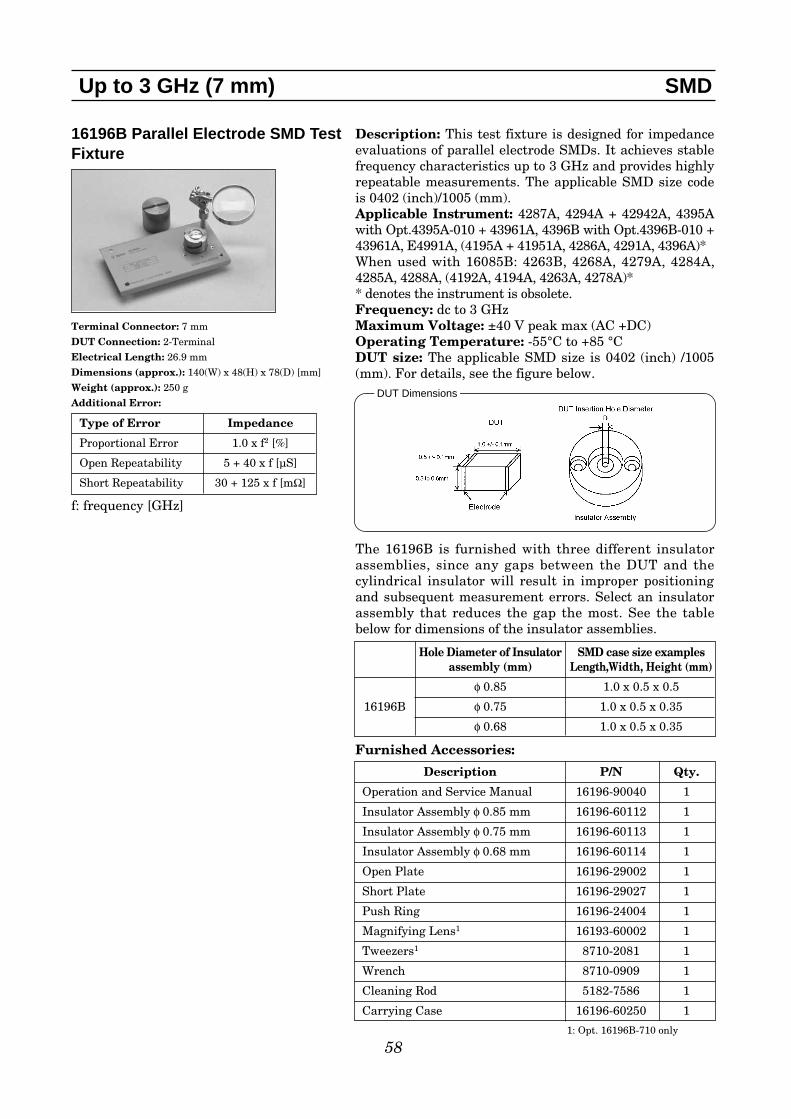
58
16196B Parallel Electrode SMD TestFixture
Terminal Connector: 7 mm
DUT Connection: 2-Terminal
Electrical Length: 26.9 mm
Dimensions (approx.): 140(W) x 48(H) x 78(D) [mm]
Weight (approx.): 250 g
Additional Error:
f: frequency [GHz]
Up to 3 GHz (7 mm) SMD
Description: This test fixture is designed for impedanceevaluations of parallel electrode SMDs. It achieves stablefrequency characteristics up to 3 GHz and provides highlyrepeatable measurements. The applicable SMD size codeis 0402 (inch)/1005 (mm).Applicable Instrument: 4287A, 4294A + 42942A, 4395Awith Opt.4395A-010 + 43961A, 4396B with Opt.4396B-010 +43961A, E4991A, (4195A + 41951A, 4286A, 4291A, 4396A)*When used with 16085B: 4263B, 4268A, 4279A, 4284A,4285A, 4288A, (4192A, 4194A, 4263A, 4278A)** denotes the instrument is obsolete.Frequency: dc to 3 GHzMaximum Voltage: ±40 V peak max (AC +DC)Operating Temperature: -55°C to +85 °CDUT size: The applicable SMD size is 0402 (inch) /1005(mm). For details, see the figure below.
The 16196B is furnished with three different insulatorassemblies, since any gaps between the DUT and thecylindrical insulator will result in improper positioningand subsequent measurement errors. Select an insulatorassembly that reduces the gap the most. See the tablebelow for dimensions of the insulator assemblies.
Furnished Accessories:
Type of Error Impedance
Proportional Error 1.0 x f2 [%]
Open Repeatability 5 + 40 x f [µS]
Short Repeatability 30 + 125 x f [mΩ]
Hole Diameter of Insulator SMD case size examplesassembly (mm) Length,Width, Height (mm)
φ 0.85 1.0 x 0.5 x 0.5
16196B φ 0.75 1.0 x 0.5 x 0.35
φ 0.68 1.0 x 0.5 x 0.35
Description P/N Qty.
Operation and Service Manual 16196-90040 1
Insulator Assembly φ 0.85 mm 16196-60112 1
Insulator Assembly φ 0.75 mm 16196-60113 1
Insulator Assembly φ 0.68 mm 16196-60114 1
Open Plate 16196-29002 1
Short Plate 16196-29027 1
Push Ring 16196-24004 1
Magnifying Lens1 16193-60002 1
Tweezers1 8710-2081 1
Wrench 8710-0909 1
Cleaning Rod 5182-7586 1
Carrying Case 16196-60250 1
DUT Dimensions
1: Opt. 16196B-710 only

59
Up to 3 GHz (7 mm) SMD
Options:16196B-710: Add the magnifying lens and tweezers
To maintain adequate measurement performance, keepthe electrodes and the short plate in good condition.Contaminants and abrasion on these parts considerablyaffect measurement results, especially for low value mea-surements. Periodic fixture cleaning and part replace-ment is recommended to avoid deterioration of measure-ment performance. The 16196x fixtures are designed withsimplicity in mind, so that an operator can easily replaceparts. Spare parts, which are likely to be abraded, aresupplied with the 16196U Maintenance Kit.
16196U Maintenance KitOpt. 16196U-010: Upper electrode, 5 piece set (commonto 16196A/B/C models)Opt. 16196U-200: Short plate for 0402 (inch)/1005 (mm)size, 5 piece set (for 16196B)Opt. 16196U-210: Lower electrode, 5 piece set (for16196B)
Compensation and Measurement: First of all, installthe appropriate insulator assembly into the fixture. Then,perform compensation. Open and short compensations arerecommended in combination with the electrical lengthcompensation before measurement. The fixture’s electri-cal length must be entered into the electrical length com-pensation function of the measurement instrument first.Next, open compensation is performed by placing the fur-nished open plate on top of the insulator assembly. Shortcompensation is performed by placing the furnished short-ing plate on top of the insulator assembly. After perform-ing open and short compensations in combination withthe electrical length compensation, the DUT is insertedinto the test fixture. Once the measurement of the DUT iscomplete, remove the DUT from the fixture, by using thefurnished push ring. Refer to the 16196A figures to seehow compensation and measurement is performed.

60
16196C Parallel Electrode SMD TestFixture
Terminal Connector: 7 mm
DUT Connection: 2-Terminal
Electrical Length: 27.1 mm
Dimensions (approx.): 140(W) x 48(H) x 78(D) [mm]
Weight (approx.): 250 g
Additional Error:
f: frequency [GHz]
Up to 3 GHz (7 mm) SMD
Description: This test fixture is designed for impedanceevaluations of parallel electrode SMDs. It achieves stablefrequency characteristics up to 3 GHz and provides highlyrepeatable measurements. The applicable SMD size codeis 0201 (inch)/0603 (mm).Applicable Instrument: 4287A, 4294A + 42942A, 4395Awith Opt.4395A-010 + 43961A, 4396B with Opt.4396B-010 +43961A, E4991A, (4195A + 41951A, 4286A, 4291A, 4396A)*When used with 16085B: 4263B, 4268A, 4279A, 4284A,4285A, 4288A, (4192A, 4194A, 4263A, 4278A)** denotes the instrument is obsolete.Frequency: dc to 3 GHzMaximum Voltage: ±40 V peak max (AC +DC)Operating Temperature: -55°C to +85°CDUT size: The applicable SMD size is 0201 (inch)/0603(mm). For details, see the figure below.
The 16196C is furnished with one insulator assembly. See thetable below for the dimensions of the insulator assembly.
Furnished Accessories:
Options:16196C-710: Add the magnifying lens and tweezers
To maintain adequate measurement performance, keepthe electrodes and the short plate in good condition.Contaminants and abrasion on these parts considerablyaffect measurement results, especially for low value mea-surements. Periodic fixture cleaning and part replace-ment is recommended to avoid deterioration of measure-ment performance. The 16196x fixtures are designed withsimplicity in mind, so that an operator can easily replaceparts. Spare parts, which are likely to be abraded, aresupplied with the 16196U Maintenance Kit.
Type of Error Impedance
Proportional Error 1.0 x f2 [%]
Open Repeatability 5 + 40 x f [µS]
Short Repeatability 30 + 125 x f [mΩ]
Hole Diameter of Insulator SMD case size examplesassembly (mm) Length,Width, Height (mm)
16196C φ 0.47 0.6 x 0.3 x 0.3
Description P/N Qty.
Operation and Service Manual 16196-90040 1
Insulator Assembly φ 0.47 mm 16196-60312 1
Open Plate 16196-29002 1
Short Plate 16196-29028 1
Push Ring 16196-24004 1
Magnifying Lens1 16193-60002 1
Tweezers1 8710-2081 1
Wrench 8710-0909 1
Cleaning Rod 5182-7586 1
DUT Dimensions
1: Opt. 16196C-710 only

61
Up to 3 GHz (7 mm) SMD
16196U Maintenance KitOpt. 16196U-010: Upper electrode, 5 piece set (commonto 16196A/B/C models)Opt. 16196U-300: Short plate for 0201 (inch)/0603 (mm)size, 5 piece set (for 16196C)Opt. 16196U-310: Lower electrode, 5 piece set (for16196C)
Compensation and Measurement: Open and shortcompensations are recommended in combination with theelectrical length compensation before measurement. Thefixture’s electrical length must be entered into the electri-cal length compensation function of the measurementinstrument first. Next, open compensation is performedby placing the furnished open plate on top of the insulatorassembly. Short compensation is performed by placing thefurnished shorting plate on top of the insulator assembly.After performing open and short compensations in combi-nation with the electrical length compensation, the DUTis inserted into the test fixture. Once the measurement ofthe DUT is complete, remove the DUT from the fixture,by using the furnished push ring. Refer to the 16196A fig-ures to see how compensation and measurement is per-formed.

16196D Parallel Electrode SMD TestFixture
Terminal Connector: 7 mm
DUT Connection: 2-Terminal
Electrical Length: 27.3 mm
Dimensions (approx.): 140(W) x 48(H) x 78(D) [mm]
Weight (approx.): 250 g
Additional Error:
f: frequency [GHz]
Up to 3 GHz (7 mm) SMD
62
Description: This test fixture is designed for impedanceevaluations of parallel electrode SMDs. It achieves stablefrequency characteristics up to 3 GHz and provides highlyrepeatable measurements. The applicable SMD size codeis 01005 (inch)/0402 (mm).Applicable Instrument: 4287A, 4294A + 42942A, 4395Awith Opt.4395A-010 + 43961A, 4396B with Opt.4396B-010 +43961A, E4991A, (4195A + 41951A, 4286A, 4291A, 4396A)*When used with 16085B: 4263B, 4268A, 4279A, 4284A,4285A, 4288A, (4192A, 4194A, 4263A, 4278A)** denotes the instrument is obsolete.Frequency: dc to 3 GHzMaximum Voltage: ±40 V peak max (AC +DC)Operating Temperature: -55°C to +85 °CDUT size: The applicable SMD size is 01005 (inch) /0402(mm). For details, see the figure below.
The 16196D is furnished with two different insulatorassemblies, since any gaps between the DUT and thecylindrical insulator will result in improper positioningand subsequent measurement errors. Select an insulatorassembly that reduces the gap the most. See the tablebelow for dimensions of the insulator assemblies.
Furnished Accessories:
Type of Error Impedance
Proportional Error 1.0 x f2 [%]
Open Repeatability 5 + 40 x f [µS]
Short Repeatability 30 + 125 x f [mΩ]
Hole Diameter of Insulator SMD case size examplesassembly (mm) Length,Width, Height (mm)
φ 0.34 0.4 x 0.2 x 0.216196D
φ 0.30 0.4 x 0.2 x 0.13 / 0.2
Description P/N Qty.
Operation and Service Manual 16196-90040 1
Insulator Assembly φ 0.34 mm 16196-60412 1
Insulator Assembly φ 0.30 mm 16196-60414 1
Open Plate 16196-29002 1
Short Plate 16196-65101 1
Push Ring 16196-24004 1
Magnifying Lens1 16193-60002 1
Tweezers1 8710-2081 1
Wrench 8710-0909 1
Cleaning Rod 5182-7586 1
Carrying Case 16196-60450 1
1: Opt. 16196D-710 only
DUT Dimensions

Options:16196D-710: Add the magnifying lens and tweezers
To maintain adequate measurement performance, keepthe electrodes and the short plate in good condition.Contaminants and abrasion on these parts considerablyaffect measurement results, especially for low value mea-surements. Periodic fixture cleaning and part replace-ment is recommended to avoid deterioration of measure-ment performance. The 16196x fixtures are designed withsimplicity in mind, so that an operator can easily replaceparts. Spare parts, which are likely to be abraded, aresupplied with the 16196U Maintenance Kit.
16196U Maintenance KitOpt. 16196U-020: Upper electrode, 5 piece set for 16196DOpt. 16196U-400: Short plate for 01005 (inch)/0402 (mm)size, 5 piece set (for 16196D)Opt. 16196U-410: Lower electrode, 5 piece set (for16196D)
Compensation and Measurement:First of all, installthe appropriate insulator assembly into the fixture. Then,perform compensation. Open and short compensations arerecommended in combination with the electrical lengthcompensation before measurement. The fixture’s electri-cal length must be entered into the electrical length com-pensation function of the measurement instrument first.Next, open compensation is performed by placing the fur-nished open plate on top of the insulator assembly. Shortcompensation is performed by placing the furnished short-ing plate on top of the insulator assembly. After perform-ing open and short compensations in combination withthe electrical length compensation, the DUT is insertedinto the test fixture. Once the measurement of the DUT iscomplete, remove the DUT from the fixture, by using thefurnished push ring. Refer to the 16196A figures to seehow compensation and measurement is performed.
Up to 3 GHz (7 mm) SMD
63

64
16197A Bottom Electrode SMD TestFixture
Terminal Connector: 7 mm
DUT Connection: 2-Terminal
Electrical Length: 14 mm
Dimensions (approx.): 160(W) x 70(H) x 86(D) [mm]
Weight (approx.): 300 g
Additional Error:
f: frequency [GHz]
E4991A with 16197A
Up to 3 GHz (7 mm) SMD
Description: This test fixture is designed for impedanceevaluations of bottom electrode SMDs. It achieves stablefrequency characteristics up to 3 GHz and provides highlyrepeatable measurements. This test fixture supports vari-ous SMD sizes, as small as 1005 (mm)/0402 (inch) and aslarge as 3225 (mm)/1210 (inch). Accommodation of the0603 (mm)/0201 (inch) size is available with option 001.Applicable Instrument: 4287A, 4294A + 42942A, 4395Awith Opt.4395A-010 + 43961A, 4396B with Opt.4396B-010+ 43961A, E4991A, (4195A + 41951A, 4286A, 4291A,4396A)*When used with 16085B: 4263B, 4268A, 4279A, 4284A,4285A, 4288A, (4192A, 4194A, 4263A, 4278A)** denotes the instrument is obsolete.Frequency: dc to 3 GHzMaximum Voltage: ±40 V peak max (AC +DC)Operating Temperature: -55°C to +85°CDUT size: See figure and table below:
Furnished Accessories:
Type of Error Impedance
Proportional Error 1.2 x f2 [%]
Open Repeatability 2 + 30 x f [µS]
Short Repeatability 30 + 150 x f [mΩ]
DUT Dimensions
Description P/N Qty.
Operation and Service Manual 16197-90000 1
Blank Device Guide 16197-25006 1
Magnifying Lens 16193-60002 1
Tweezers 8710-2081 1
Wrench 8710-0909 1
Carrying Case 16197-60050 1
Case for Shorting Devices 1540-0692 1
Short Plate See below See below
Standard Option Applicable SMD Size
SMD Size Code L x W [mm] H [mm]
3216 (mm)/1210 (inch) (3.2±0.15) x (2.5±0.15) H ≥ 0.4
3216 (mm)/1206 (inch) (3.2±0.15) x (1.6±0.15) H ≥ 0.4
2012 (mm)/0805 (inch) (2.0±0.15) x (1.25±0.15) H ≥ 0.4
1608 (mm)/0603 (inch) (1.6±0.15) x (0.8±0.15) H ≥ 0.4
1005 (mm)/0402 (inch) (1.0±0.1) x (0.5±0.1) H ≥ 0.4
Option 16197A-001 Applicable SMD Size
SMD Size Code L x W [mm] H [mm]
0603 (mm)/0201 (inch) (0.6±0.03) x (0.3±0.03) H ≥ 0.25
Test fixture overview
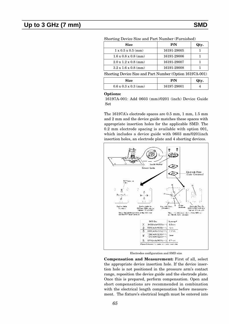
65
Up to 3 GHz (7 mm) SMD
Shorting Device Size and Part Number (Furnished)
Shorting Device Size and Part Number (Option 16197A-001)
Options:16197A-001: Add 0603 (mm)/0201 (inch) Device GuideSet
The 16197A’s electrode spaces are 0.5 mm, 1 mm, 1.5 mmand 2 mm and the device guide matches these spaces withappropriate insertion holes for the applicable SMD. The0.2 mm electrode spacing is available with option 001,which includes a device guide with 0603 mm/0201inchinsertion holes, an electrode plate and 4 shorting devices.
Compensation and Measurement: First of all, selectthe appropriate device insertion hole. If the device inser-tion hole is not positioned in the pressure arm’s contactrange, reposition the device guide and the electrode plate.Once this is prepared, perform compensation. Open andshort compensations are recommended in combinationwith the electrical length compensation before measure-ment. The fixture’s electrical length must be entered into
Size P/N Qty.
1 x 0.5 x 0.5 (mm) 16191-29005 1
1.6 x 0.8 x 0.8 (mm) 16191-29006 1
2.0 x 1.2 x 0.8 (mm) 16191-29007 1
3.2 x 1.6 x 0.8 (mm) 16191-29008 1
Size P/N Qty.
0.6 x 0.3 x 0.3 (mm) 16197-29001 4
Electrodes configuration and SMD size

66
the electrical length compensation function of the mea-surement instrument first. Next, open compensation isperformed by not placing anything in the device insertionhole. Short compensation is performed by placing the fur-nished shorting device in the device insertion hole. Afterperforming open and short compensations in combinationwith the electrical length compensation, the DUT isinserted into the device insertion hole. Once the measure-ment of the DUT is complete, remove the DUT from thefixture. The following figures show how compensation andmeasurement is performed.
Up to 3 GHz (7 mm) SMD
Compensation and measurement
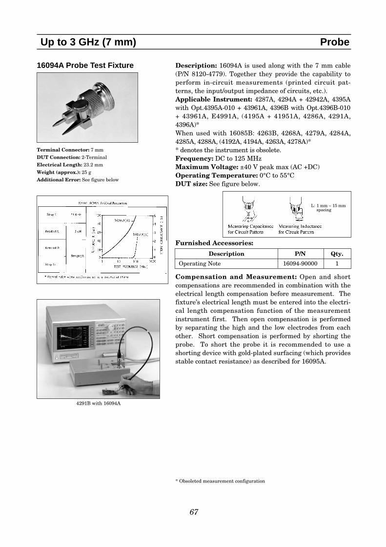
67
16094A Probe Test Fixture
Terminal Connector: 7 mm
DUT Connection: 2-Terminal
Electrical Length: 23.2 mm
Weight (approx.): 25 g
Additional Error: See figure below
Up to 3 GHz (7 mm) Probe
Description: 16094A is used along with the 7 mm cable(P/N 8120-4779). Together they provide the capability toperform in-circuit measurements (printed circuit pat-terns, the input/output impedance of circuits, etc.). Applicable Instrument: 4287A, 4294A + 42942A, 4395Awith Opt.4395A-010 + 43961A, 4396B with Opt.4396B-010+ 43961A, E4991A, (4195A + 41951A, 4286A, 4291A,4396A)*When used with 16085B: 4263B, 4268A, 4279A, 4284A,4285A, 4288A, (4192A, 4194A, 4263A, 4278A)** denotes the instrument is obsolete.Frequency: DC to 125 MHz Maximum Voltage: ±40 V peak max (AC +DC) Operating Temperature: 0°C to 55°CDUT size: See figure below.
Furnished Accessories:
Compensation and Measurement: Open and shortcompensations are recommended in combination with theelectrical length compensation before measurement. Thefixture’s electrical length must be entered into the electri-cal length compensation function of the measurementinstrument first. Then open compensation is performedby separating the high and the low electrodes from eachother. Short compensation is performed by shorting theprobe. To short the probe it is recommended to use ashorting device with gold-plated surfacing (which providesstable contact resistance) as described for 16095A.
4291B with 16094A
L: 1 mm ~ 15 mmspacing
Description P/N Qty.
Operating Note 16094-90000 1
* Obsoleted measurement configuration

68
16200B External DC Bias Adapter
Terminal Connector: 7 mm
DC BIAS Input connector: BNC(f)
Voltage Monitor connector: BNC(f)
Dimensions (approx.): 165(W) x 65 (H) x 130(D) [ mm]
Weight (approx.): 500 g
Up to 3 GHz (7 mm) DC Bias Accessories
Description: This test fixture is designed to operate withthe 4286A or 4291A/B. It allows you to supply a bias cur-rent across the device of up to 5Adc through a 7 mm portby using an external dc current source. Applicable Instruments: 4287A, 4294A + 42942A, 4395Awith Opt.4395A-010 + 43961A, 4396B with Opt.4396B-010 +43961A, E4991A, (4195A + 41951A, 4286A, 4291A, 4396A)*When used with 16085B: 4263B, 4268A, 4279A, 4284A,4285A, 4288A, (4192A, 4194A, 4263A, 4278A)** denotes the instrument is obsolete.Frequency: 1 MHz to 1 GHzDC Bias: Up to 5A, 40 VOperating Temperature: 0°C to 55°CApplicable Fixtures: 16191A, 16192A, 16193A, 16194A,16196A/B/C/D, 16197A, 16092A, 16093A/BFurnished Accessories:
Shorting Devices’ Size and Part Number (option 16200B-001)
Load Devices’ Size and Part Number (option 16200B-001)
Options:16200B-001: For 4291B users, Add Working Std Set
Compensation and Measurement: When using the4291B, follow these instructions: Perform open, short,load and low-loss calibration at the 7 mm test port of the4291B. Connect the 16200B to the 7 mm test port, andconnect the test fixture onto the 16200B. Open, short, andload compensations are recommended before measure-ment. Use the short bars and 51 Ω SMD resistors fur-nished with 16200B’s option 16200B-001 to perform shortand load compensation respectively.When using other instruments, follow these instructions:Connect the 16200B to the 7 mm test port of the measure-ment instrument. Perform open, short, load (and low-losscalibration) at the 7 mm test port of the 16200B. Then,connect the test fixture onto the 16200B and performopen, short, and electrical length compensations in theusual manner.
Description P/N Qty.
Operation and Service Manual 16200-90011 1
Size P/N Qty.
0.6 x 0.3 x 0.3 (mm) 16197-29001 2
1 x 0.5 x 0.5 (mm) 16191-29005 2
1.6 x 0.8 x 0.8 (mm) 16191-29006 2
2.0 x 1.2 x 0.8 (mm) 16191-29007 2
3.2 x 1.6 x 0.8 (mm) 16191-29008 2
Size P/N Qty.
0.6 x 0.3 x 0.3 (mm) NA 5
1 x 0.5 x 0.5 (mm) NA 5
1.6 x 0.8 x 0.8 (mm) NA 5
2.0 x 1.2 x 0.8 (mm) NA 5
3.2 x 1.6 x 0.8 (mm) NA 5
Connection example

69
16453A Dielectric Material Test Fixture
Terminal Connector: 7 mm
Dimensions (approx.): 130(H) x 50(W) x 60(D) [mm]
Weight (approx.): 600 g
Measurement Accuracy (including the E4991A):
Up to 3 GHz (7 mm) Material
Description: The 16453A is designed for accurate dielec-tric constant and loss tangent measurements on theE4991A. It employs the parallel plate method, whichsandwiches the material between two electrodes to form acapacitor. E4991A measures the capacitance createdfrom the fixture, and option E4991A-002 firmware calcu-lates the relative complex permittivity as described in the16451B. Adjustment to insure parallel electrodes isrequired when using the 16451B. This adjustment is notrequired with 16453A because the fixture has a flexibleelectrode that adjusts automatically to the material sur-face.
Applicable Instruments: E4991A with Opt.E4991A-002, (4291A/B with Opt.4291A/B-002)** denotes the instrument is obsolete.Frequency: 1 MHz to 1 GHzMaximum Voltage: ±40 V peak max (AC+DC)Operating Temperature: -55°C to 200°CWhen Option E4991A-007 temperature characteristic testkit is used with E4991A, the operating temperature rangeis between -55°C and +150°C.Material Size:
Furnished Accessories:
Compensation and Measurement: Open, short andload compensations are recommended before measure-ment. Open compensation is performed by separating thehigh and the low electrodes from each other. Short com-pensation is performed by connecting the high and lowelectrodes together. Load compensation is performed byusing the furnished load material. After performing open,short and load compensations, the material under test isinserted into the test fixture.
Typical Permittivity (er’) Measurement Accuracy (@ thickness = 1 mm)
Typical Loss Tangent (tan δ) Measurement Accuracy (@ thickness = 1 mm)
Description P/N Qty.
Fixture Holder 16453-01213 1
Load 16453-60021 1
Tweezers 8710-2081 1
Carrying Case 16453-60011 1
Operation and Service Manual 16453-90000 1
Diameter ≥ 15 mm
Thickness 0.3 mm ~ 3 mm
E4991A with 16453A
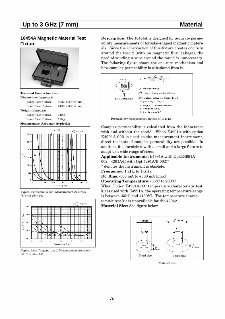
70
16454A Magnetic Material Test Fixture
Terminal Connector: 7 mm
Dimensions (approx.):(Large Test Fixture) 30(D) x 35(H) [mm]
(Small Test Fixture) 24(D) x 30(H) [mm]
Weight (approx.): (Large Test Fixture) 140 g
(Small Test Fixture) 120 g
Measurement Accuracy (typical.):
Up to 3 GHz (7 mm) Material
Description: The 16454A is designed for accurate perme-ability measurements of toroidal-shaped magnetic materi-als. Since the construction of this fixture creates one turnaround the toroid (with no magnetic flux leakage), theneed of winding a wire around the toroid is unnecessary.The following figure shows the one-turn mechanism andhow complex permeability is calculated from it.
Complex permeability is calculated from the inductancewith and without the toroid. When E4991A with optionE4991A-002 is used as the measurement instrument,direct readouts of complex permeability are possible. Inaddition, it is furnished with a small and a large fixture toadapt to a wide range of sizes.Applicable Instruments: E4991A with Opt.E4991A-002, (4291A/B with Opt.4291A/B-002)** denotes the instrument is obsolete.Frequency: 1 kHz to 1 GHz, DC Bias: -500 mA to +500 mA (max) Operating Temperature: -55°C to 200°CWhen Option E4991A-007 temperature characteristic testkit is used with E4991A, the operating temperature rangeis between -55°C and +150°C. The temperature charac-teristic test kit is unavailable for the 4294A.Material Size: See figure below.
Typical Permeability (µr’) Measurement Accuracy (@ h* ln c/b = 10)
Typical Loss Tangent (tan δ) Measurement Accuracy (@ h* ln c/b = 10)
Permeability measurement method of 16454A
Material size
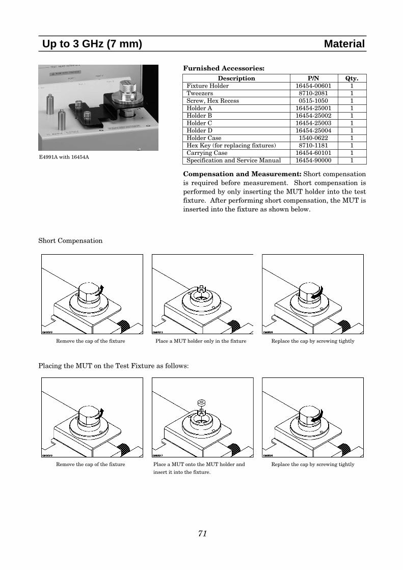
71
Up to 3 GHz (7 mm) Material
Placing the MUT on the Test Fixture as follows:
Furnished Accessories:
Compensation and Measurement: Short compensationis required before measurement. Short compensation isperformed by only inserting the MUT holder into the testfixture. After performing short compensation, the MUT isinserted into the fixture as shown below.
Description P/N Qty.Fixture Holder 16454-00601 1Tweezers 8710-2081 1Screw, Hex Recess 0515-1050 1Holder A 16454-25001 1Holder B 16454-25002 1Holder C 16454-25003 1Holder D 16454-25004 1Holder Case 1540-0622 1Hex Key (for replacing fixtures) 8710-1181 1Carrying Case 16454-60101 1Specification and Service Manual 16454-90000 1
Remove the cap of the fixture Place a MUT holder only in the fixture Replace the cap by screwing tightly
Remove the cap of the fixture Place a MUT onto the MUT holder and
insert it into the fixture.
Replace the cap by screwing tightly
Short Compensation
E4991A with 16454A

72
This page intentionally left blank.

73
DC (High resistance)
Test Fixtures for DC (High Resistance) Measurements
Frequency Up to 110 MHz Up to 3 GHzRange (Terminal Configuration: 4-Terminal Pair) (Terminal Configuration: 7 mm)
Measurement 4192A, 4194A, 4263A/B, 4268A, 4291A/B, 4294A + 42942A, 4395A Instruments 4278A, 4279A, 4284A, 4285A, 4288A, w/Opt.010 + 43961A, 4396A/B w/Opt.010
4294A + 43961A, 4286A, 4287A, E4991AAny 4TP instruments (excluding 4294A) +16085B
Frequency DC (High Resistance Measurement) 1 kHz (Milliohm Measurement)
Measurement 4339A/B, 4349A/B 4338A/BInstruments
Applicable Instrument
Test Fixture Frequency Applicable Instrument
16339A DC 4339A/B
16118A DC 4339A/B
16117B/C DC 4349A/B
16117E DC 4349A/B
16008B DC 4339A/B

16339A Component Test Fixture
Terminal Connector:
* Interlock Connector enables and disables the application of source voltage from the measurement instrument.
DUT Connection: 2-Terminal (with triaxial cable)
Dimensions (approx.): 200(W) x 140(H) x 230 (D) [mm]
Cable Length (approx.): 0.8 m
Weight (approx.): 2200 g
74
DC (High resistance) SMD & Lead Components
Description: The 16339A is designed to operate specifi-cally with 4339B. It is provided with three componentmodules, which are used to hold SMD, lead and varioustype of devices. Electrical noise effects are reduced by theemployment of a shielded case. A built-in interlocking cir-cuit enables safe high-voltage measurements.Applicable Instruments: 4339B, (4339A)** denotes the instrument is obsolete.Frequency: DCMaximum Voltage: 1000 VMaximum Current: 10 mAResistance Measurement Range: 1 x 10³ to 2 x 10¹⁶ ΩOperating Temperature: 0°C to 55°CDUT Size: For Alligator Clip and Flat Table, lead diame-ter ≤5 mm
Furnished Accessories:
Compensation and Measurement: Open compensationis recommended before measurement. When using theaxial lead module, have no DUT connected to the elec-trodes. When using the SMD module, separate the highand low electrodes from each other. The separationshould be equivalent in size to the DUT’s width. Whenusing the alligator clip and flat table, remove the alligatorclips from the input terminals of the test fixture. Afterpreparing the open condition of the respective module,close the top cover and then perform open compensation.Finally, the DUT is inserted into the respective module.The following figure shows the three component modules.
Type Connector
Input Triaxial (special screw-type)
Output High Voltage BNC (special type)
Control Interlock connector*
4339B with 16339A
SMD module
Description P/N Qty.Axial Lead Module 16339-60102 1SMD Module 16339-60101 1Flat Table 16339-60004 1Miniature Banana-Plug cable 16339-61621 2100 kΩ Output Resistor 16339-61001 11 MΩ Output Resistor 16339-61002 110 MΩ Output Resistor 16339-61003 1100 MΩ Output Resistor 16339-61004 1Alligator Clip 8710-1984 2Carrying Case 16339-60001 1Operation and Service Manual 16339-90010 1
Component module configurations
SMD module Axial Lead module Alligator clip and Flat table
DUT Dimensions

16118A Tweezers Test Fixture
Terminal Connector:
* Interlock Connector enables and disables the application of source voltage from the measurement instrument.
DUT Connection: 2-Terminal (with triaxial cable)
Cable Length (approx.): 1 m
Weight (approx.): 410 g
75
DC (High resistance) SMD
Type Connector
Input Triaxial (special screw-type)
Output High Voltage BNC (special type)
Control Interlock connector*
Description: The 16118A is designed to operate specifi-cally with 4339B. The tweezer’s contacts, which makes iteasy to hold SMD. Electrical noise effects are reduced bythe employment of shielded-cables. A built-in interlock-ing circuit enables safe high-voltage measurements. Applicable Instruments: 4339B, (4339A)** denotes the instrument is obsolete.Frequency: DCMaximum Voltage: 100 VMaximum Current: 0.87 mAResistance Measurement Range: 1 x 10⁷ to 1 x 10¹¹ ΩOperating Temperature: 0°C to 55°CDUT Size: See figure below
Furnished Accessories:
Compensation and Measurement: Open compensationis recommended before measurement. Separate the elec-trodes from each other. The separation should be equiva-lent in size to the DUT’s width. After performing opencompensation, the DUT is sandwiched by the tweezers’contacts and is measured.
4339B with 16118A
Description P/N Qty.
Operation and Service Manual 16118-90010 1
DUT Dimensions

16117B Low Noise Test Leads
Terminal Connector:
* Interlock connector enables and disables the application of source voltage from the measurement instrument.
DUT Connection: 2-Terminal (with triaxial cable)
Cable Length (approx.): 1 m (connector to clips)
Weight (approx.): 280 g
76
DC (High resistance) Other Components
Description: The 16117B is designed to operate specifi-cally with 4339B. With Option 16117B-003 wide jawclips, it is capable of holding DUTs with large terminals.The clips can be replaced with probes (Option 16117B-001) for measurements of small DUTs such as PC boardsor IC sockets. Option 16117B-002 enables the construc-tion of simple custom-made test leads. Electrical noiseeffects are reduced by the employment of shielded-cables.A built-in interlocking circuit enables safe high-voltagemeasurements.Applicable Instruments: 4339B, (4339A)** denotes the instrument is obsolete.Frequency: DCMaximum Voltage: 1000 VMaximum Current: 0.5 mAResistance Measurement Range: 1 x 10³ to 1 x 10¹¹ ΩOperating Temperature: 0°C to 55°CDUT Size: For clips (Opt. 16117B-003), lead diameter ≤30 mm
For probes and sockets, see figure below:
Furnished Accessories:
Options:16117B-001: Add Pin Probes (2 ea.)16117B-002: Add Soldering Sockets (2 ea.)16117B-003: Add Alligator Clips (2 ea.)Compensation and Measurement: Open compensationis recommended before measurement. Separate the testclips (or probes) from each other. After performing opencompensation, the DUT is connected to the clips (orprobes). The DUT can be measured in two configurations:floating and grounded. The connections are shown in thefigure below:
Floating and grounded DUT measurement
Type Connector
Input Triaxial (special screw-type)
Output High Voltage BNC (special type)
Control Interlock connector*
Description P/N Qty.
Operation and Service Manual 16117-90040 1
Floating DUT Measurement Grounded DUT Measurement

77
DC (High resistance) Other Components
16117E Low Noise Test Leads
Terminal Connector: Triaxial (m)
Cable Length (approx.): 1 m (connector to connector)
Weight (approx.): 130 g
16117C Low Noise Test Leads
Terminal Connector:
* Interlock connector enables and disables the application of source voltage from the measurement instrument.
DUT Connection: 2-Terminal (with triaxial cable)
Cable Length (approx.): 1 m (connector to connector)
Weight (approx.): 290 g
Description: The 16117C is designed to operate specifi-cally with 4339B. It comes with a separate triaxial (spe-cial screw-type) female connector and a high-voltage BNC(special type) female connector, so that the terminal con-figuration of the 4339A/B can be converted to any otherconfiguration. Therefore, custom-made test fixtures caneasily be constructed. Applicable Instruments: 4339B, (4339A)** denotes the instrument is obsolete.Frequency: DCMaximum Voltage: 1000 VMaximum Current: 10 mAResistance Measurement Range: 1 x 10³ to 1 x 10¹⁶ ΩOperating Temperature: 0°C to 55°CFurnished Accessories:
1. High-voltage BNC cable. This connector provides thesource voltage to the 16117C. This is a high-voltageBNC connector and is not compatible with standardBNC connectors.
2. Triaxial cable. The measured signal is carried on thecenter conductor of this connector. This is a specialscrew-type triaxial connector and is not compatiblewith standard triaxial connectors.
3. Interlock cable. This connector enables the interlockfunction which enables and disables the application ofsource voltage from the 4339A/B when the interlockline is connected and disconnected respectively.
4. High-voltage BNC (special type) female connector5. Triaxial (special screw-type) female connector.
Adapter features
Description: The 16117E is designed to operate specifi-cally with 4349A*/B. It is used to connect the 4349A*/Band the DUT. Hence, four 16117E test leads are requiredwhen using four channels of the 4349A/B. Its cable isequipped with triaxial connectors on both ends. It is alsofurnished with a triaxial female connector for connectionwith the DUT and external voltage source.Applicable Instruments: 4349A/B OnlyFrequency: DCMaximum Voltage: 250 VOperating Temperature: 0°C to 45°CFurnished Accessories:
Type Connector
Input Triaxial (special screw-type)
Output High Voltage BNC (special type)
Control Interlock connector*
Description P/N Qty.
Triaxial (special screw-type) female connector 1250-2228 1
High Voltage BNC (special type) female connector 1250-2317 1
Operation and Service Manual 16117-90031 1
Description P/N Qty.
Triaxial female connector 1250-1906 1

16008B Resistivity Cell
Terminal Connector:
* Interlock Connector enables and disables theapplication of source voltage from the measure-ment instrument.
DUT Connection: 2-Terminal (with triaxial cable)
Dimensions (approx.): 240(W) x 180(H) x 240(D) [mm]
Cable Length (approx.): 1.2 m (connector to electrodes)
Weight (approx.): 7000 g
78
DC (High resistance) Material
Description: The 16008B is designed to operate specifi-cally with 4339B. It is used to measure surface or volumeresistance/resistivity of insulation materials. The follow-ing figures show the block diagrams of resistivity mea-surements.
Volume resistivity is measured across the material (MUT)by the unguarded and guarded electrodes. Surface resistiv-ity, on the other hand, is measured along the surface of theMUT (between the guarded and the unguarded electrodes).Notice that the role of the guard and unguarded electrodesswitch, when measuring volume and surface resistivity.16008B is provided with three different electrode sizes tomeet size requirements by different measurement stan-dards. The guarded electrode eliminates measurementerrors due to the edge effect and arbitrary contact pres-sure can be applied to the material under test. It is alsoequipped with a high-voltage protection cover to shut offpower when opened.Applicable Instruments: 4339B, (4339A)** denotes the instrument is obsolete.Frequency: DCMaximum Voltage: 1000 VMaximum Current: 10 mAResistance Measurement Range: Volume Resistivity Measurement Range:
up to 4.0 x 10¹⁸ ΩcmSurface Resistivity Measurement Range:
up to 4.0 x 10¹⁷ ΩOperating Temperature: -30°C to +100°C (excludingselector switch) Material Size: Select an electrode so that outer diameterof guarding electrode is smaller than the DUT’s diameter.See figure and table below for more details:
Volume resistivity measurement Surface resistivity measurement
Electrode sizes and applicable material sizes
Type Connector
Input Triaxial (special screw-type)
Output High Voltage BNC (special type)
Control Interlock connector*
D1 D2 D3 Ordering Information DMain Electrode Guard Electrode Guard Electrode _____ Material Size
(Inner Diameter) (Outer Diameter)26 mm 38 mm 48 mm Supplied with Opt.16008B-001/002 50 mm* to 125 mm50 mm 70 mm 80 mm Standard - equipped 82 mm* to 125 mm76 mm 88 mm 98 mm Supplied with Opt.16008B-001 100 mm* to 125 mm
* Outer Diameter of Guard Electrode + 2 mmThickness: 10µm to 10 mm

79
DC (High resistance) Material
Furnished Accessories:
Options:16008B-001: Add 26 & 76 mm diameter electrodes16008B-002: Add 26 mm diameter electrodeCompensation and Measurement: Using the selectorswitch on the 16008B, select either the volume resistivityor surface resistivity measurement configuration. Opencompensation is recommended before measurement andwhen the measurement configuration is switched.Separate the upper electrode from the main electrode byturning the contact pressure load knob until the upperelectrode does not move. Then, close the top cover andperform open compensation. After open compensation, thematerial under test (MUT) is placed on the main electrodeand the upper electrode is placed over it. Next, turn theload knob to adjust the electrode contact pressure on theMUT. Close the top cover and measure the MUT's surfaceor volume resistivity. It is vital to make measurements, which are compatible toa certified test method (standard). It is shown below thatthe 16008B can make resistivity measurements which arecompatible with ASTM D257 Standard Test Methods forDC Resistance or Conductance of Insulating Materials. Inthe figure and tables shown below, the size and shape iscompared for two pairs of electrodes: one that is specifiedin ASTM D257 and the one that is used with the 16008BResistivity Cell. The similarity implies that the 16008B iscompatible with ASTM D257.
Compatibility with ASTM D257
Choice 1 Choice 2A 76 mm 25 mmB 88 mm 38 mmC 100 mm 50 mmD 100 mm 50 mm
Opt. 16008B-001 Opt. 16008B-001/002A 76 mm 26 mmB 88 mm 38 mmC 98 mm 48 mmD 110 mm 110 mm
ASTM D257's recommended electrode sizes 16008B electrode sizes
Description P/N Qty.
Operation and Service Manual 16008-90011 1

80
This page intentionally left blank.
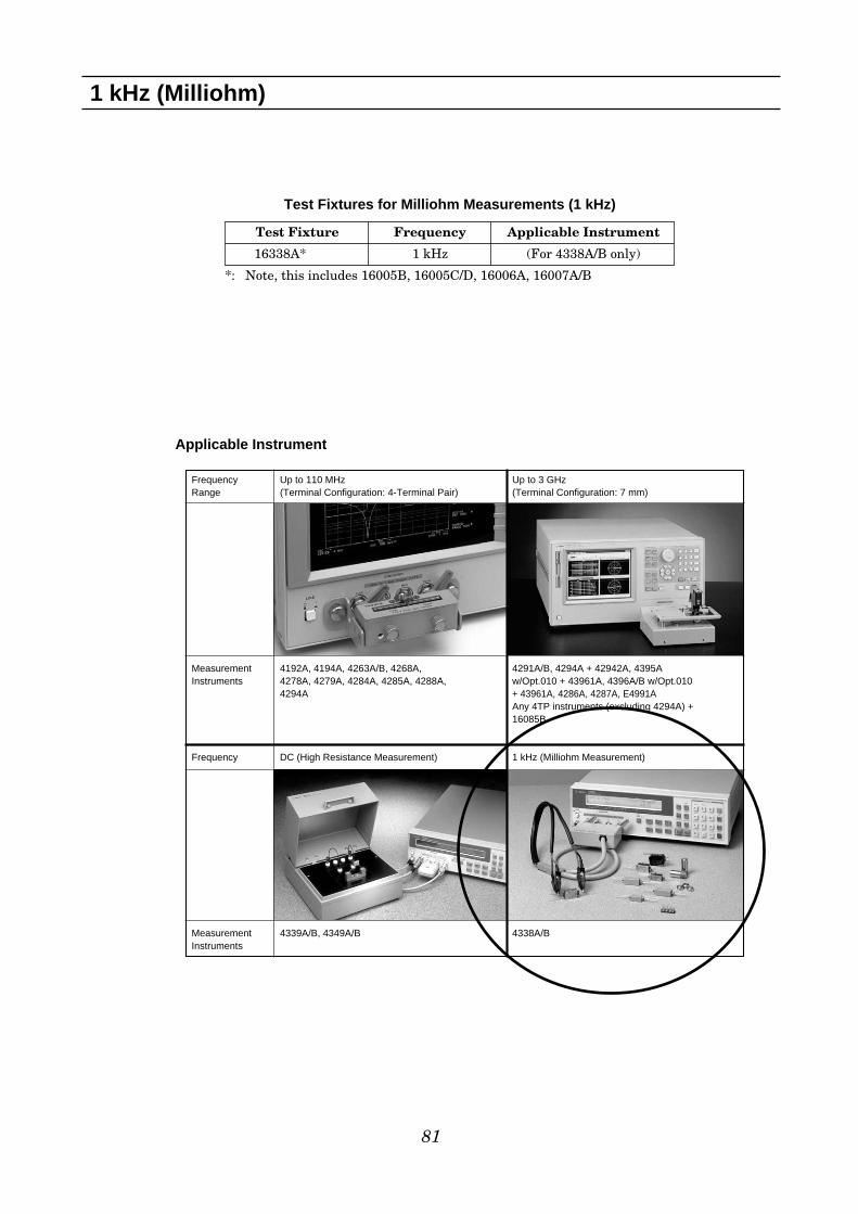
81
1 kHz (Milliohm)
Frequency Up to 110 MHz Up to 3 GHzRange (Terminal Configuration: 4-Terminal Pair) (Terminal Configuration: 7 mm)
Measurement 4192A, 4194A, 4263A/B, 4268A, 4291A/B, 4294A + 42942A, 4395A Instruments 4278A, 4279A, 4284A, 4285A, 4288A, w/Opt.010 + 43961A, 4396A/B w/Opt.010
4294A + 43961A, 4286A, 4287A, E4991AAny 4TP instruments (excluding 4294A) +16085B
Frequency DC (High Resistance Measurement) 1 kHz (Milliohm Measurement)
Measurement 4339A/B, 4349A/B 4338A/BInstruments
Applicable Instrument
Test Fixtures for Milliohm Measurements (1 kHz)
Test Fixture Frequency Applicable Instrument
16338A* 1 kHz (For 4338A/B only)
*: Note, this includes 16005B, 16005C/D, 16006A, 16007A/B

16338A Test Lead Kit
Terminal Connector: 4-Terminal, BNC
DUT Connection: 4-Terminal
82
1 kHz (Milliohm) Various Components
Description: The 16338A contains four types of testleads and a mating cable, which are designed to operatewith the 4338B. These test leads can be mixed ormatched depending on the type of sample being mea-sured. The test leads and mating cable are shown in thefigure below:
Applicable Instruments: 4338B, (4338A)** denotes the instrument is obsolete.Frequency: 1 kHz Operating Temperature: 0°C to 55°CFurnished Accessories:
Compensation and Measurement: Short compensationis recommended before measurement. When using the16005B or the 16005C/D, first connect the voltage termi-nals together and the current terminals together. Then,connect the two pairs of voltage and current terminalstogether. When using the 16006A, firmly press the probesagainst a shorting plate. Make sure that all four elec-trodes of the probes contact via the shorting plate and areplaced closely to each other. The shorting plate shouldhave very low residual impedance, so a high conductivemetal plate should be used. When using 16007A/B, hold ashorting plate with the alligator clips. Make sure that thevoltage leads (or black leads) are next to each other.
Available test leads
Description P/N Qty.
Kelvin Clip Leads (large) 16005B 2
Kelvin Clip Leads (small, red) 16005C 1
Kelvin Clip Leads (small, black) 16005D 1
Pin-Type Probe Leads 16006A 2
Alligator Clip Lead (red) 16007A 1
Alligator Clip Lead (black) 16007B 1
Mating Cable 16143B 1
Carrying Case 16338-60001 1
Operation and Service Manual 16338-90000 1
16143BMating Cable
16005BKeivin Clip Leads(large clip)
16005C/DKelvin Clip Leads(IC clip)
16006APin-type ProbeLeads
16007A/BAlligator ClipLeads
Connect:16005B16005C/D16006A16007A/B
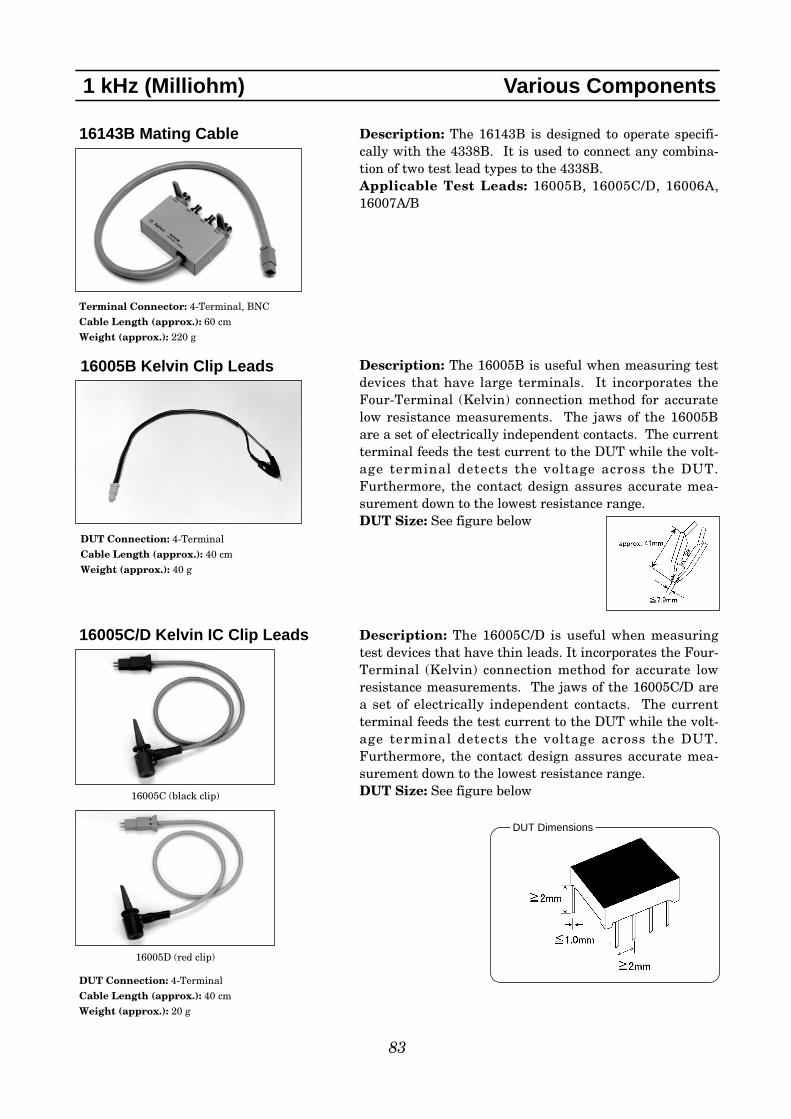
83
1 kHz (Milliohm) Various Components
16143B Mating Cable
Terminal Connector: 4-Terminal, BNC
Cable Length (approx.): 60 cm
Weight (approx.): 220 g
Description: The 16143B is designed to operate specifi-cally with the 4338B. It is used to connect any combina-tion of two test lead types to the 4338B. Applicable Test Leads: 16005B, 16005C/D, 16006A,16007A/B
16005B Kelvin Clip Leads
DUT Connection: 4-Terminal
Cable Length (approx.): 40 cm
Weight (approx.): 40 g
Description: The 16005B is useful when measuring testdevices that have large terminals. It incorporates theFour-Terminal (Kelvin) connection method for accuratelow resistance measurements. The jaws of the 16005Bare a set of electrically independent contacts. The currentterminal feeds the test current to the DUT while the volt-age terminal detects the voltage across the DUT.Furthermore, the contact design assures accurate mea-surement down to the lowest resistance range.DUT Size: See figure below
16005C/D Kelvin IC Clip Leads
DUT Connection: 4-Terminal
Cable Length (approx.): 40 cm
Weight (approx.): 20 g
Description: The 16005C/D is useful when measuringtest devices that have thin leads. It incorporates the Four-Terminal (Kelvin) connection method for accurate lowresistance measurements. The jaws of the 16005C/D area set of electrically independent contacts. The currentterminal feeds the test current to the DUT while the volt-age terminal detects the voltage across the DUT.Furthermore, the contact design assures accurate mea-surement down to the lowest resistance range. DUT Size: See figure below16005C (black clip)
16005D (red clip)
DUT Dimensions

84
1 kHz (Milliohm) Various Components
16007A/B Kelvin Alligator Clip Leads
DUT Connection: 4-Terminal
Cable Length (approx.): 40 cm
Weight (approx.): 20 g
Description: The 16007A/B is designed for standardFour-Terminal measurements. Each pair of test leadshas a separate alligator clip for voltage and current termi-nals. The 16007A is furnished with red covers and the16007B is furnished with black covers.DUT Size: lead diameter ≤4 mm
16007A (red clip)
16007B (black clip)
16006A Pin-type Leads
DUT Connection: 4-Terminal
Cable Length (approx.): 40 cm
Weight (approx.): 15 g
Description: The 16006A is designed for press-on contactmeasurements such as printed board conductivity orthrough-hole measurements. The probe tip is a voltageterminal and the outer conductor is a current terminal.The probe tip is spring-loaded, so that both terminalsfirmly contact the DUT.

16064B LED Display/Trigger Box
Terminal Connector: Handler Interface Cable
Cable Length (approx.): 1.5 m
Dimensions (approx.): 200(W) x 40(H) x 100(D) [mm]
Weight (approx.): 800 g
85
Other Accessories
Description: The 16064B is designed to operate specifical-ly with 4263A*/B, 4338A*/B, and 4339A*/B. Comparatorresults which are sent from the measurement instrument,are displayed by LEDs on the 16064B. The parametersthat are displayed are shown in the table below:
Furthermore, it can lock the front panel keys of the mea-surement instrument and trigger a measurement.Applicable Instruments: 4263B, 4338B, 4339B, (4263A,4338A, 4339A)** denotes the instrument is obsolete.Operating Temperature: 0°C to 55°CFurnished Accessories:
LED Indicator 4338A*/B 4339A*/B 4263A*/B
Primary LOW
Primary IN
Primary HIGH
Secondary LOW
Secondary IN
Secondary HIGH
Over Current
Over Voltage
No Contact
Description P/N Qty.
Operation and Service Manual 16064-90010 1
Test fixture overview
1. Primary result indicator (LOW)2. Primary result indicator (IN) 3. Primary result indicator (HIGH)4. Secondary result indicator (LOW) 5. Secondary result indicator (IN) 6. Secondary result indicator (HIGH) 7. Over current indicator 8. Over voltage indicator 9. No contact indicator 10. Key Lock Switch11. Trigger Key12. Handler Interface Connection Cable

16190B Performance Test Kit
Terminal Connector: 7 mm
Dimensions (approx.): 350(W) x 100(H) x 270(D) [mm]
Weight (approx.): 2.0 kg
86
Other Accessories
Description: The 16190B is a performance test kitdesigned to verify the impedance measurement accuracyof LCR meters or impedance analyzers that have a 7 mmmeasurement terminal. Refer to the instrument’s opera-tion/service manual for the method of using these stan-dards.Applicable Instrument: E4991A, (4286A, 4291A)*4287A, 4291B, 4294A + 42942AFurnished Accessories:
Description P/N Qty.
Airline, 50 Ω, 7 mm N/A 1
Cap, Protection 1401-0123 2
50 Ω Termination N/A 1
Open Termination N/A 1
Short Termination N/A 1
Cap, Termination Protection 16190-25011 3
Wrench, 1/2 and 8/15, Open End 8710-1770 1
Carrying Case 16190-60250 1
Floppy Diskette for Calibration Data N/A 1
Calibration Report N/A 1
Operating Note 16190-90010 1
* Obsolete Instrument
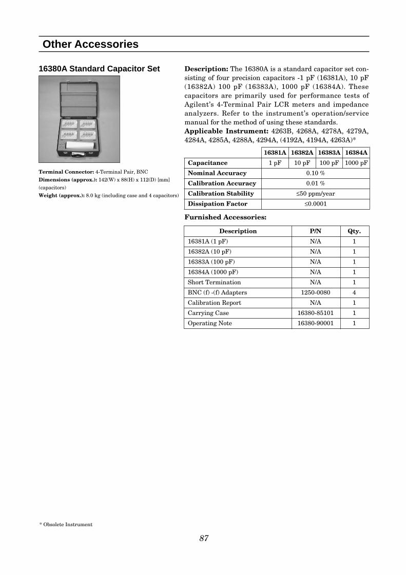
16380A Standard Capacitor Set
Terminal Connector: 4-Terminal Pair, BNC
Dimensions (approx.): 142(W) x 88(H) x 112(D) [mm]
(capacitors)
Weight (approx.): 8.0 kg (including case and 4 capacitors)
87
Other Accessories
Description: The 16380A is a standard capacitor set con-sisting of four precision capacitors -1 pF (16381A), 10 pF(16382A) 100 pF (16383A), 1000 pF (16384A). Thesecapacitors are primarily used for performance tests ofAgilent’s 4-Terminal Pair LCR meters and impedanceanalyzers. Refer to the instrument’s operation/servicemanual for the method of using these standards.Applicable Instrument: 4263B, 4268A, 4278A, 4279A,4284A, 4285A, 4288A, 4294A, (4192A, 4194A, 4263A)*
Furnished Accessories:
Description P/N Qty.
16381A (1 pF) N/A 1
16382A (10 pF) N/A 1
16383A (100 pF) N/A 1
16384A (1000 pF) N/A 1
Short Termination N/A 1
BNC (f) -(f) Adapters 1250-0080 4
Calibration Report N/A 1
Carrying Case 16380-85101 1
Operating Note 16380-90001 1
16381A 16382A 16383A 16384A
Capacitance 1 pF 10 pF 100 pF 1000 pF
Nominal Accuracy 0.10 %
Calibration Accuracy 0.01 %
Calibration Stability ≤50 ppm/year
Dissipation Factor ≤0.0001
* Obsolete Instrument
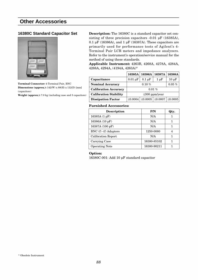
16380C Standard Capacitor Set
Terminal Connector: 4-Terminal Pair, BNC
Dimensions (approx.): 142(W) x 88(H) x 112(D) [mm]
(capacitors)
Weight (approx.): 7.0 kg (including case and 3 capacitors)
88
Other Accessories
Description: The 16380C is a standard capacitor set con-sisting of three precision capacitors -0.01 µF (16385A), 0.1 µF (16386A), and 1 µF (16387A). These capacitors areprimarily used for performance tests of Agilent’s 4-Terminal Pair LCR meters and impedance analyzers.Refer to the instrument’s operation/service manual for themethod of using these standards.Applicable Instrument: 4263B, 4268A, 4278A, 4284A,4288A, 4294A, (4194A, 4263A)*
Furnished Accessories:
Option:16380C-001: Add 10 µF standard capacitor
Description P/N Qty.
16385A (1 pF) N/A 1
16386A (10 pF) N/A 1
16387A (100 pF) N/A 1
BNC (f) -(f) Adapters 1250-0080 4
Calibration Report N/A 1
Carrying Case 16380-85102 1
Operating Note 16380-90211 1
16385A 16386A 16387A 16388A
Capacitance 0.01 µF 0.1 µF 1 µF 10 µF
Nominal Accuracy 0.10 % 0.05 %
Calibration Accuracy 0.01 %
Calibration Stability ≤300 ppm/year
Dissipation Factor ≤0.0004 ≤0.0005 ≤0.0007 ≤0.0005
* Obsolete Instrument
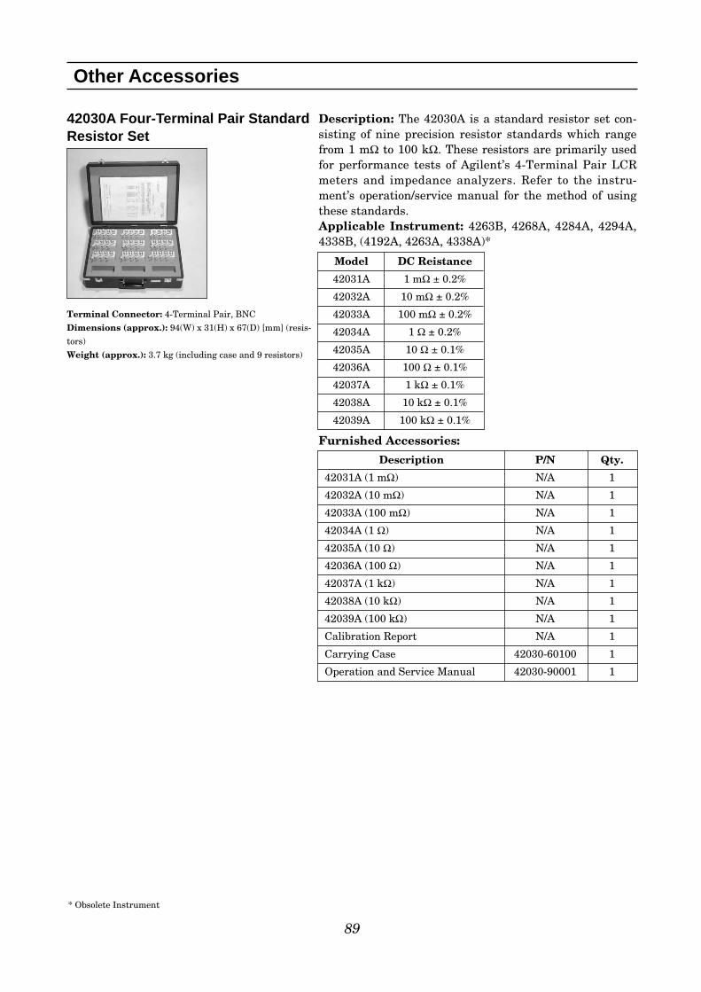
42030A Four-Terminal Pair StandardResistor Set
Terminal Connector: 4-Terminal Pair, BNC
Dimensions (approx.): 94(W) x 31(H) x 67(D) [mm] (resis-
tors)
Weight (approx.): 3.7 kg (including case and 9 resistors)
89
Other Accessories
Description: The 42030A is a standard resistor set con-sisting of nine precision resistor standards which rangefrom 1 mΩ to 100 kΩ. These resistors are primarily usedfor performance tests of Agilent’s 4-Terminal Pair LCRmeters and impedance analyzers. Refer to the instru-ment’s operation/service manual for the method of usingthese standards.Applicable Instrument: 4263B, 4268A, 4284A, 4294A,4338B, (4192A, 4263A, 4338A)*
Furnished Accessories:
Description P/N Qty.
42031A (1 mΩ) N/A 1
42032A (10 mΩ) N/A 1
42033A (100 mΩ) N/A 1
42034A (1 Ω) N/A 1
42035A (10 Ω) N/A 1
42036A (100 Ω) N/A 1
42037A (1 kΩ) N/A 1
42038A (10 kΩ) N/A 1
42039A (100 kΩ) N/A 1
Calibration Report N/A 1
Carrying Case 42030-60100 1
Operation and Service Manual 42030-90001 1
Model DC Reistance
42031A 1 mΩ ± 0.2%
42032A 10 mΩ ± 0.2%
42033A 100 mΩ ± 0.2%
42034A 1 Ω ± 0.2%
42035A 10 Ω ± 0.1%
42036A 100 Ω ± 0.1%
42037A 1 kΩ ± 0.1%
42038A 10 kΩ ± 0.1%
42039A 100 kΩ ± 0.1%
* Obsolete Instrument

90
42090A Open Termination
Terminal Connector: 4-Terminal Pair, BNC
Dimensions (approx.): 94(W) x 31(H) x 67(D) [mm]
Weight (approx.): 120 g
Other Accessories
Description: The 42090A is an open termination and isprimarily used for performance tests of Agilent’s 4-Terminal Pair LCR meters and impedance analyzers.Refer to the instrument’s operation/service manual for themethod of using this standard.Applicable Instrument: 4263B, 4268A, 4279A, 4284A,4285A, 4288A, 4294A, (4192A, 4263A, 4278A)*
42091A Short Termination
Terminal Connector: 4-Terminal Pair, BNC
Dimensions (approx.): 94(W) x 31(H) x 67(D) [mm]
Weight (approx.): 120 g
Description: The 42091A is a short termination and isprimarily used for performance tests of Agilent’s 4-Terminal Pair LCR meters and impedance analyzers.Refer to the instrument’s operation/service manual for themethod of using this standard.Applicable Instrument: 4263B, 4268A, 4279A, 4284A,4285A, 4294A, 4338B, (4192A, 4263A, 4338A, 4278A)*
* Obsolete Instrument
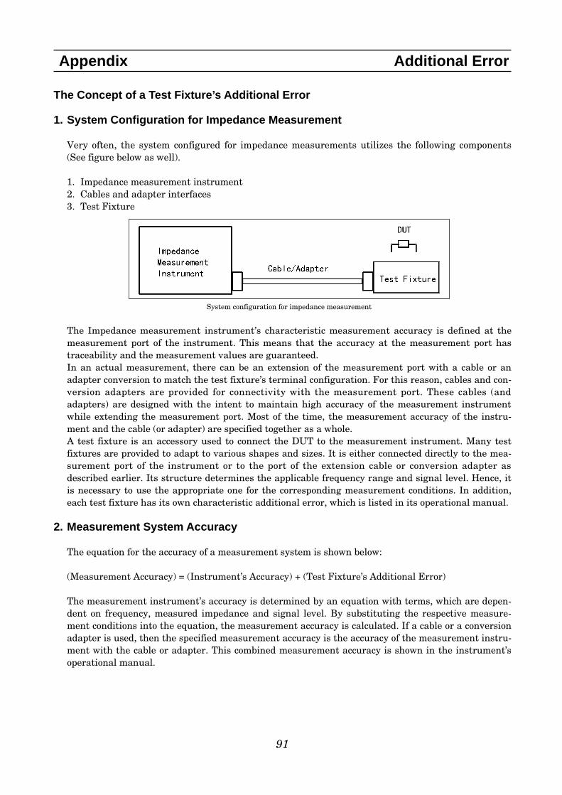
The Concept of a Test Fixture’s Additional Error
1. System Configuration for Impedance Measurement
Very often, the system configured for impedance measurements utilizes the following components(See figure below as well).
1. Impedance measurement instrument2. Cables and adapter interfaces3. Test Fixture
System configuration for impedance measurement
The Impedance measurement instrument’s characteristic measurement accuracy is defined at themeasurement port of the instrument. This means that the accuracy at the measurement port hastraceability and the measurement values are guaranteed. In an actual measurement, there can be an extension of the measurement port with a cable or anadapter conversion to match the test fixture’s terminal configuration. For this reason, cables and con-version adapters are provided for connectivity with the measurement port. These cables (andadapters) are designed with the intent to maintain high accuracy of the measurement instrumentwhile extending the measurement port. Most of the time, the measurement accuracy of the instru-ment and the cable (or adapter) are specified together as a whole. A test fixture is an accessory used to connect the DUT to the measurement instrument. Many testfixtures are provided to adapt to various shapes and sizes. It is either connected directly to the mea-surement port of the instrument or to the port of the extension cable or conversion adapter asdescribed earlier. Its structure determines the applicable frequency range and signal level. Hence, itis necessary to use the appropriate one for the corresponding measurement conditions. In addition,each test fixture has its own characteristic additional error, which is listed in its operational manual.
2. Measurement System Accuracy
The equation for the accuracy of a measurement system is shown below:
(Measurement Accuracy) = (Instrument’s Accuracy) + (Test Fixture’s Additional Error)
The measurement instrument’s accuracy is determined by an equation with terms, which are depen-dent on frequency, measured impedance and signal level. By substituting the respective measure-ment conditions into the equation, the measurement accuracy is calculated. If a cable or a conversionadapter is used, then the specified measurement accuracy is the accuracy of the measurement instru-ment with the cable or adapter. This combined measurement accuracy is shown in the instrument’soperational manual.
91
Appendix Additional Error

The equation for the test fixture’s additional error is shown below:
Ze = ± A + (Zs/Zx + Yo•Zx) × 100 (%)De = Ze/100 (D ≤ 0.1)
Ze : Additional Error for Impedance (%)De : Additional Error for Dissipation FactorA : Test Fixture’s Proportional Error (%)Zs/Zx × 100 : Short Offset Error (%)Yo•Zx × 100 : Open Offset Error (%)Zs : Test Fixture’s short Repeatability (Ω)Yo : Test Fixture’s open Repeatability (S)Zx : Measured Impedance Value of DUT(Ω)
Proportional error, open and short repeatability are mentioned in the test fixture’s operational manu-al and in this accessory guide. By inputting the measurement impedance and frequency (proportionalerror, open and short repeatability are usually a function of frequency) into the above equation, thefixture’s additional error can be calculated.
Proportional Error:The term, proportional error (A), was derived from the error factor, which causes the absolute imped-ance error to be proportional to the impedance being measured. If only the first term is taken out ofthe above equation and multiplied by Zx, then ∆Z = A•Zx (Ω). This means that the absolute value ofthe impedance error will always be A times the measured impedance. The largeness of proportionalerror is dependent upon how complicated the test fixture’s construction is. Conceptually, it is depen-dent upon the stability of each element of the fixture’s equivalent circuit model. From previous expe-rience, proportional error is proportional to the frequency squared.
Short Offset Error:The term, Zs/Zx × 100, is called short offset error. If Zx is multiplied to this term, then ∆Z = Zs (Ω). Itcan be concluded that this term affects the absolute impedance error, by adding an offset. Shortrepeatability (Zs) is determined from the variations in multiple measurements of the test fixture inshort condition. After performing short compensation, the measured values of the short condition willdistribute around 0 in the complex impedance plane. The maximum value of the impedance vector isdefined as short repeatability. This is shown in the figure below. The larger short repeatability is themore difficult it is to measure small impedance values. For example, if the test fixture’s shortrepeatability is 100 mΩ, then the additional error of an impedance measurement under 100 mΩ willbe more than 100%. In essence, short repeatability is made up of a resistance and an inductance part,which become larger as the frequency becomes higher.
Definition of short repeatability
92
Appendix Additional Error

Open Offset Error:The term, Yo•Zx × 100 is called open offset error. If the same analysis is carried out with admittance,then it can be concluded that this term also affects the absolute admittance error, by adding an offset.Open repeatability (Yo) is determined from the variations in multiple measurements of the test fix-ture in open condition. As shown in the figure below, the maximum value of the admittance vector inthe complex admittance plane is defined as open repeatability. The larger open repeatability is, themore difficult it is to measure large impedance values. Open repeatability is made up of a resistanceand a capacitance part, which become larger as the frequency becomes higher.
Definition of open repeatability
3. New Market Trends and the Additional Error for Test Fixtures
New Devices:Recently, the debut of extremely low ESR capacitors and the trend to use capacitors at much higherfrequencies, have made low impedance measurements more strongly demanded than in the past. Asa result, the test fixture’s short repeatability has become increasingly important. In the figure below,the relationship between proportional error, short offset error and frequency are shown when mea-suring low impedance. Notice that when the measured impedance is less than 100 mΩ, short offseterror influences the entirety of the test fixture’s additional error. As shown in the figure below, whenthe DUT's impedance is 100 mΩ and the test fixture’s short repeatability is 10 mΩ, the short offseterror will be 10%. Since the proportional error is minimal in low frequencies, the additional error willbe 10% as well.For the additional error of test fixtures, up until now, it was common to just specify the proportionalerror (A). As shown in the 10Ω measurement case (same figure down below), if the measured imped-ance is large in comparison to the test fixture’s short repeatability, then short offset error can beignored completely. This is the reason why open and short offset error was not specified previously.Test fixtures that are only specified with proportional error in this accessory guide are due to thisreason. On the contrary, for measured impedance from 1Ω to 10 kΩ proportional error (A) alone issufficient to express the test fixture’s additional error.
Relationship between proportional error, short offset error and frequency when measuring low impedance
93
Appendix Additional Error

Terminal Connector Method:In order to make short repeatability small, there are test fixtures which utilize the 4-Terminal con-nector method (for example 16044A). By employing this technique, the effect of contact resistance isreduced and short repeatability is drastically improved. As a result, the range of accurate low imped-ance measurements is vastly expanded.In the figure below, the difference between the 2-Terminal connector and the 4-Terminal connector isshown. In a 2-Terminal connector, the contact resistance, which exists between the fixture’s contactand the DUT, is measured together with the DUT’s impedance. Contact resistance cannot be elimi-nated by compensation because the value changes each time the DUT is contacted.
2-Terminal and 4-Terminal connector techniques
In a 4-Terminal connector, the voltage and current terminals are separate. Since the input imped-ance of the voltmeter is large, no current flows to the voltage terminals. Hence, the voltage that isapplied across the DUT can be accurately detected without being affected by the contact resistance.Also, the current that flows through the DUT flows directly into the current terminal and is accurate-ly detected without being affected by the contact resistance. Due to the reasons stated above, it ispossible to eliminate the effect of contact resistance and realize a small short repeatability.
Test Fixture’s Adaptability for a Particular Measurement:In order to make use of what has been discussed previously, the test fixture’s adaptability for a par-ticular measurement will be focused upon. To see whether a test fixture is adaptable, it is importantto think about the test fixture’s additional error (proportional error, short and open repeatability),measurement impedance and the test frequency range.
If the measurement impedance is in the 1 to 10 kΩ range, use only proportional error to calculate theadditional error of the test fixture. It is fine to assume that this is a close approximation to the fix-ture’s additional error.
If the measurement impedance is not in this range, use proportional error, short and open offseterrors to calculate the test fixture’s additional error. Recent test fixtures have all three terms speci-fied in their operational manual, so use these values for the calculation.
Some of the recent test fixtures (16044A), due to their structure, have different performance charac-teristics with different measurement instruments. For these test fixtures refer to their operationalmanual for more details about the specifications.
So, how are test fixtures, which are not specified with short and open repeatability, assessed whetherthey are adaptable or not? This assessment is made possible by using the following method toapproximate short and open repeatability. To measure a test fixture’s short repeatability, measurethe impedance of the short condition after performing short compensation. Take the shorting plateout of the fixture and then insert it back in. Measure the short condition again. By repeating thisprocess at least 50 times, it will show the variations in the short condition (See figure below). Thefinal step to determine an approximation of short repeatability is to add a margin to the values
94
Appendix Additional Error

obtained. For open repeatability, measure the admittance of the test fixture’s open condition. In thesame way, determine open repeatability by measuring at least 50 times.
Measurement of short repeatability (16034G)
Measurement SettingsMeasurement Instrument : 4294AMeasurement Frequency : 40 Hz-10 MHzMeasurement Parameter : Z-θCompensation : Performed short CompensationBandwidth : 3Measurement Method : Inserted the shorting plate, measured the short condition, and then
removed the shorting plate. Repeated this for 50 times.Display Method : Overlaying traces by using the Accumulate Mode
Lastly of all, a method to visually analyze the accurate measurement range of a test fixture is intro-duced. This method is only appropriate when all three error-terms (proportional error, open andshort repeatability) are known. The table below shows the additional error of 16034G. The wholeequation, with all three terms can be solved for measurement impedance rather than additionalerror, for example when additional error is equal to 0.5%. If the obtained impedance values are plot-ted with measurement impedance (y-axis) against frequency (x-axis), a graph similar to the oneshown down below can be obtained. The shaded area shows the range of impedance that can be mea-sured with an additional error better than 0.5%. In the same way, other graphs can be drawn withother additional error values to better visualize the accuracy that can be obtained for a given imped-ance and frequency range. The operational manuals of recent test fixtures present such graphs.
Additional Error of 16034G
Specifications ofShort Repeatability
Actual Measurementof Short Repeatability
95
Appendix Additional Error
Additional error ≤ 0.5%
Type of Error Impedance
Proportional Error 0.5 x (f/10)2 [%]
Open Repeatability 5 + 500 x (f/10) [nS]
Short Repeatability 10 + 13 x (f/10) [mΩ]
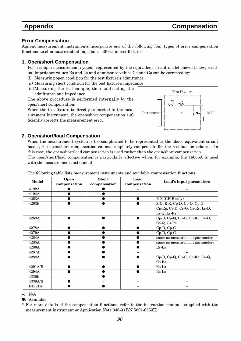
Error CompensationAgilent measurement instruments incorporate one of the following four types of error compensationfunctions to eliminate residual impedance effects in test fixtures:
1. Open/short CompensationFor a simple measurement system, represented by the equivalent circuit model shown below, resid-ual impedance values Rs and Ls and admittance values Co and Go can be corrected by:(i) Measuring open condition for the test fixture’s admittance.(ii) Measuring short condition for the test fixture’s impedance(iii)Measuring the test sample, then subtracting the
admittance and impedance.The above procedure is performed internally by theopen/short compensation.When the test fixture is directly connected to the mea-surement instrument, the open/short compensation suf-ficiently corrects the measurement error.
2. Open/short/load CompensationWhen the measurement system is too complicated to be represented as the above equivalent circuitmodel, the open/short compensation cannot completely compensate for the residual impedance. Inthis case, the open/short/load compensation is used rather than the open/short compensation.The open/short/load compensation is particularly effective when, for example, the 16065A is usedwith the measurement instrument.
The following table lists measurement instruments and available compensation functions.
–: N/A: Available* For more details of the compensation functions, refer to the instruction manuals supplied with the
measurement instrument or Application Note 346-3 (P/N 5091-6553E)
96
Appendix Compensation
Test Fixture
Instrument DUT
ModelOpen Short Load
Load’s input parameterscompensation compensation compensation
4192A – –4194A – –4263A R-X (GPIB only)4263B Z-Q, R-X, Cp-D, Cp-Q, Cp-G,
Cp-Rp, Cs-D, Cs-Q, Cs-Rs, Ls-D, Ls-Q, Ls-Rs
4268A Cp-D, Cp-Q, Cp-G, Cp-Rp, Cs-D, Cs-Q, Cs-Rs
4278A Cp-D, Cp-G4279A Cp-D, Cp-G4284A same as measurement parameters4285A same as measurement parameters4286A Rs-Ls4287A – –4288A Cp-D, Cp-Q, Cp-G, Cp-Rp, Cs-Q,
Cs-Rs4291A/B Rs-Ls4294A Rs-Ls4338B – – –4339A/B – – –E4991A – –
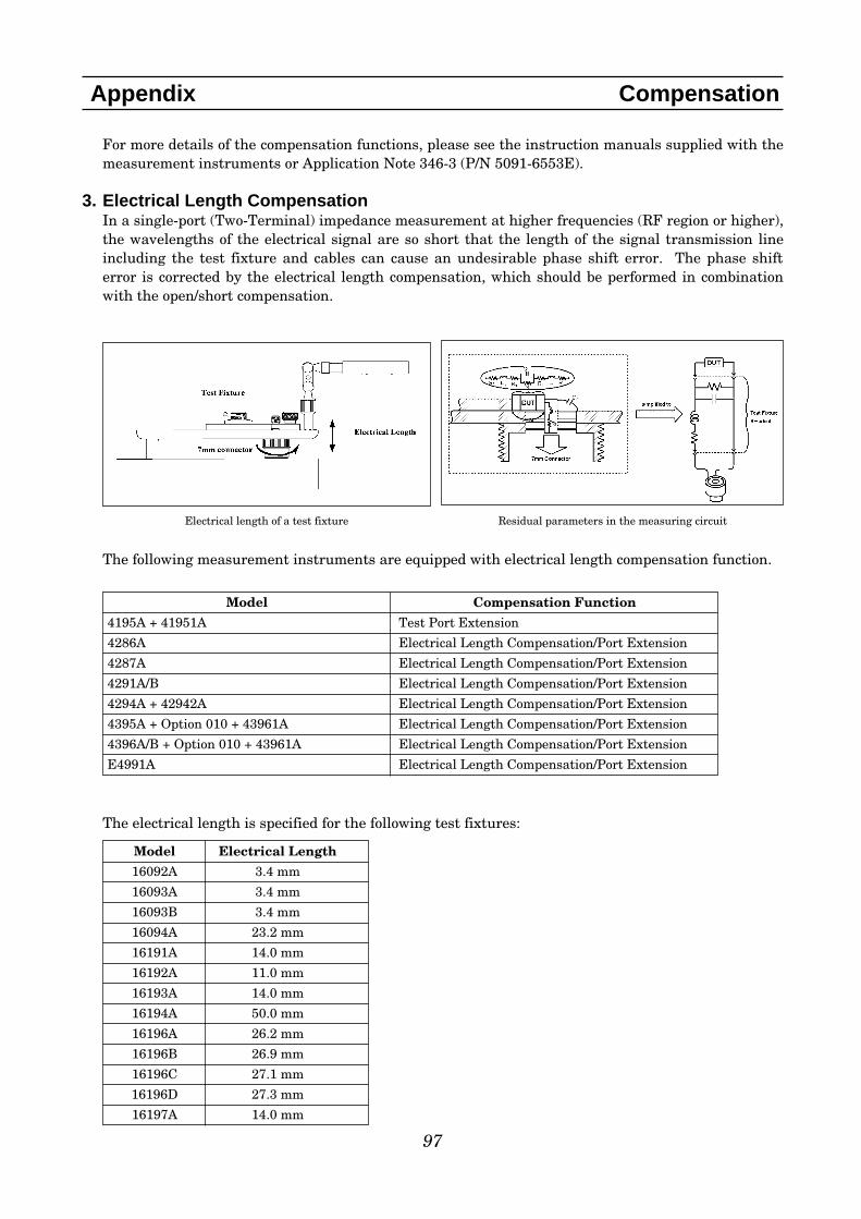
97
Appendix Compensation
For more details of the compensation functions, please see the instruction manuals supplied with themeasurement instruments or Application Note 346-3 (P/N 5091-6553E).
3. Electrical Length CompensationIn a single-port (Two-Terminal) impedance measurement at higher frequencies (RF region or higher),the wavelengths of the electrical signal are so short that the length of the signal transmission lineincluding the test fixture and cables can cause an undesirable phase shift error. The phase shifterror is corrected by the electrical length compensation, which should be performed in combinationwith the open/short compensation.
The following measurement instruments are equipped with electrical length compensation function.
The electrical length is specified for the following test fixtures:
Model Compensation Function
4195A + 41951A Test Port Extension
4286A Electrical Length Compensation/Port Extension
4287A Electrical Length Compensation/Port Extension
4291A/B Electrical Length Compensation/Port Extension
4294A + 42942A Electrical Length Compensation/Port Extension
4395A + Option 010 + 43961A Electrical Length Compensation/Port Extension
4396A/B + Option 010 + 43961A Electrical Length Compensation/Port Extension
E4991A Electrical Length Compensation/Port Extension
Model Electrical Length
16092A 3.4 mm
16093A 3.4 mm
16093B 3.4 mm
16094A 23.2 mm
16191A 14.0 mm
16192A 11.0 mm
16193A 14.0 mm
16194A 50.0 mm
16196A 26.2 mm
16196B 26.9 mm
16196C 27.1 mm
16196D 27.3 mm
16197A 14.0 mm
Electrical length of a test fixture Residual parameters in the measuring circuit
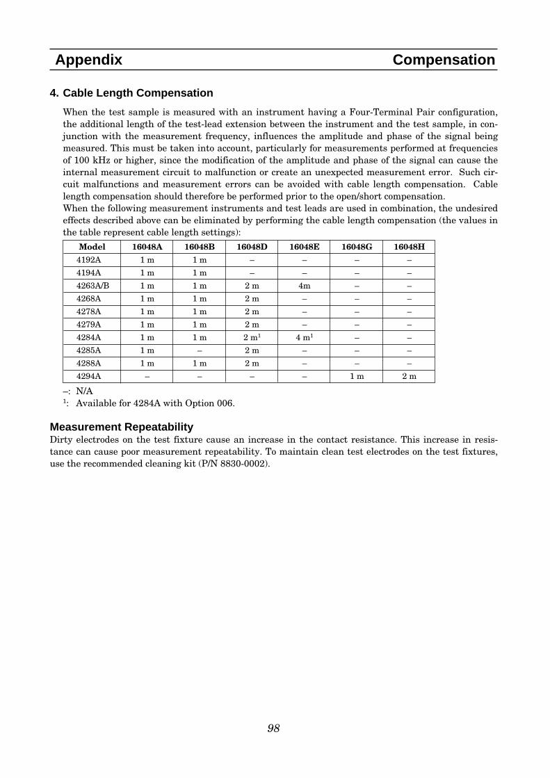
4. Cable Length Compensation
When the test sample is measured with an instrument having a Four-Terminal Pair configuration,the additional length of the test-lead extension between the instrument and the test sample, in con-junction with the measurement frequency, influences the amplitude and phase of the signal beingmeasured. This must be taken into account, particularly for measurements performed at frequenciesof 100 kHz or higher, since the modification of the amplitude and phase of the signal can cause theinternal measurement circuit to malfunction or create an unexpected measurement error. Such cir-cuit malfunctions and measurement errors can be avoided with cable length compensation. Cablelength compensation should therefore be performed prior to the open/short compensation.When the following measurement instruments and test leads are used in combination, the undesiredeffects described above can be eliminated by performing the cable length compensation (the values inthe table represent cable length settings):
–: N/A1: Available for 4284A with Option 006.
Measurement RepeatabilityDirty electrodes on the test fixture cause an increase in the contact resistance. This increase in resis-tance can cause poor measurement repeatability. To maintain clean test electrodes on the test fixtures,use the recommended cleaning kit (P/N 8830-0002).
98
Appendix Compensation
Model 16048A 16048B 16048D 16048E 16048G 16048H
4192A 1 m 1 m – – – –
4194A 1 m 1 m – – – –
4263A/B 1 m 1 m 2 m 4m – –
4268A 1 m 1 m 2 m – – –
4278A 1 m 1 m 2 m – – –
4279A 1 m 1 m 2 m – – –
4284A 1 m 1 m 2 m1 4 m1 – –
4285A 1 m – 2 m – – –
4288A 1 m 1 m 2 m – – –
4294A – – – – 1 m 2 m

99
Index
Model Number Name Applicable Measurement Instrument (s) Page (s)
16005B Kelvin Clip Leads 4338A/B with 16143B 79
16005C/D Kelvin IC Clip Leads refer to 16005B 79
16006A Pin-Type Leads refer to 16005B 80
16007A/B Alligator Clip Leads refer to 16005B 80
16008B Resistivity Cell 4339A/B 74-75
16034E SMD/Chip Test Fixture 4192A, 4194A, 4263A/B, 4268A, 4278A, 4279A, 144284A, 4285A, 4288A, 4294A
16034G SMD/Chip Test Fixture, Small refer to 16034E 15
16034H SMD/Chip Test Fixture, General refer to 16034E 16
16043A/B 3-Terminal SMD Test Fixture refer to 16034E 20-22
16044A SMD/Chip Test Fixture, refer to 16034E 17-18Four-Terminal, 10 MHz
16047A Axial and Radial Test Fixture refer to 16034E 10
16047D Axial and Radial Test Fixture refer to 16034E 11
16047E Axial and Radial Test Fixture, refer to 16034E 12110 MHz
16048A One Meter Test Leads, BNC 4192A, 4194A, 4263A/B, 4268A, 4278A, 4279A, 264284A, 4285A, 4288A
16048B One Meter Test Leads, SMC 4192A, 4194A, 4263A/B, 4268A, 4278A, 4279A, 264284A, 4288A
16048D Two Meter Test Leads, BNC 4263A/B, 4268A, 4278A, 4279A, 4284A, 4285A, 4288A 27
16048E Four Meter Test Leads, BNC 4263A/B, 4284A 27
16048G One Meter Test Leads, BNC, 4294A 28110 MHz
16048H Two Meter Test Leads, BNC, 4294A 28110 MHz
16060A Transformer Test Fixture 4263A/B (w/Option 001) 13
16064B LED Display/Trigger Box 4263A/B, 4338A/B, 4339A/B, 4349A/B 81
16065A Ext. Voltage Bias with Safety 4192A, 4194A, 4263A/B, 4268A, 4278A, 4279A, 32Cover (≤200 vdc) 4284A, 4285A, 4288A, 4294A

100
Index
Model Number Name Applicable Measurement Instrument (s) Page (s)
16065C External Bias Adapter 4263A/B, 4268A, 4278A, 4288A 32(≤40 vdc)
16085B Four-Terminal Pair to 4192A, 4194A, 4263A/B, 4268A, 4278A, 4279A, 57 mm Adapter 4284A, 4285A, 4288A
16089A/B Kelvin Clip Leads 4192A, 4194A, 4263A/B, 4268A, 4278A, 4279A, 23-25/C/D/E 4284A, 4285A, 4288A, 4294A
16092A RF Spring Clip : Axial, Radial 4192A, 4193A, 4194A, 4194A + 41941A, 4195A 45and SMD 41951A, 4263A/B, 4268A, 4278A, 4279A, 4284A,
4285A, 4286A, 4287A, 4288A, 4291A/B, 4294A +42942A, 4396A/B (Opt. 010) + 43961A, 4395A(Opt. 010) + 43961A, E4991A
16093A RF Two Terminal Binding Post refer to 16092A 46
16093B RF Three Terminal Binding Post refer to 16092A 47
16094A RF Probe Tip/Adapter refer to 16092A 66
16095A LF Impedance Probe 4192A, 4263A/B, 4268A, 4278A, 4279A, 4284A, 304285A, 4288A
16117B Low Noise Test Leads 4339A/B 74
16117C Low Noise Test Leads 4339A/B 75
16117E Low Noise Test Leads 4349A/B 75
16118A SMD/Chip Tweezers 4339A/B 73
16143B Mating Cable 4338A/B 81
16190B Performance Test Kit E4991A, 4286A, 4291A, 4287A, 4291B, 4294A+ 8542942A
16191A Bottom-Electrode SMD Test 4192A, 4193A, 4194A, 4194A + 41941A, 4195A + 48-49Fixture 41951A, 4263A/B, 4268A, 4278A, 4279A, 4284A,
4285A, 4286A, 4287A, 4288A, 4291A/B, 4294A + 42942A, 4396A/B (Opt. 010) + 43961A, 4395A (Opt. 010) + 43961A, E4991A
16192A Parallel Electrode SMD Test refer to 16191A 50-51Fixture
16194A High Temperature Component refer to 16191A 52-53Text Fixture
16196A/B/C/D Parallel Electrode SMD Test refer to 16191A 54-62Fixure
16197A Bottom Electrode SMD Test refer to 16191A 63-65Fixure

101
Index
Model Number Name Applicable Measurement Instrument (s) Page (s)
16200B External DC Bias Adapter 4286A, 4287A, 4291A/B, 4396A/B w/opt.010+43961A 674395A w/opt.010+43961A, E4991A
16314A Four-Terminal Balun 4192A, 4194A, 4263A/B, 4268A, 4278A, 4279A, 294284A, 4285A, 4288A, 4294A
16334A SMD/Chip Tweezers 4192A, 4194A, 4263A/B, 4268A, 4278A, 4279A, 194284A, 4285A, 4288A, 4294A
16338A Test Lead Kit for 4338A/B 4338A/B 80
16339A Component Test Fixture for 4339A/B 724339A/B
16380A C Standards Set 4263B, 4268A, 4278A, 4279A, 4284A, 4285A, 4288A, 854294A, 4192A, 4194A, 4263A
16380C C Standards Set 4263B, 4268A, 4278A, 4284A, 4288A, 4294A, 864194A, 4263A
16451B Dielectric Material Test Fixture 4192A, 4194A, 4263A/B, 4268A, 4278A, 4279A, 38-414284A, 4285A, 4288A, 4294A
16452A Liquid Test Fixture 4194A, 4284A, 4285A ,4294A 42-43
16453A Dielectric Material Test Fixture 4291A/B 68
16454A Magnetic Material Test Fixture 4291A/B, 4294A 69-70
42030A Four-Terminal Pair Standard 4263B, 4268A, 4284A, 4294A, 4338B, 4192A, 4263A, 87Resistor Set 4338A
42090A Open Termination 4263B, 4268A, 4278A, 4279A, 4284A, 4285A, 4288A, 884294A, 4192A, 4263A
42091A Short Termination 4263B, 4268A, 4278A, 4279A, 4284A, 4285A, 4294A, 884338B, 4192A, 4263A, 4338A
42841A Bias Current Source 4284A, 4285A (w/option 002) 33
42842A/B Bias Current 20A/40A Test 4284A (w/option 002) 34-35Fixture
42842C Bias Current 10A Test Fixture 4285A (w/option 002) 36
42843A Bias Current Cable 4284A (w/option 002) 37
P/N 42851-61100 SMD Test Fixture 4285A (w/option 002) 36
42941A Impedance Probe Kit 4294A 31
42942A Four-Terminal Pair to 7 mm 4294A 5Adapter

102
Index
Test Fixture Selection By SMD Size
Size1
6
FixtureContacts
4-Terminal Pair(up to 110MHz)
7mm(up to 3GHz)
Parallel 16034G 16196CBottom – 16197A2
Parallel 16196DBottom
–
Parallel 16034G 16196B, 16192A3
Bottom – 16197AParallel 16034E4/G, 16044A5 16196A, 16192A3
Bottom – 16197AParallel 16034E4/G, 16044A5 16192A3
Bottom 16043A/B 16197A, 16191A3
Parallel 16034E4/G, 16044A5 16192A3
Bottom 16043A/B 16197A, 16191A3
Parallel 16034E4/G, 16044A5 16192A3
Bottom 16043A/B 16191A3
Notes: 1. Sizes are in EIA/EIAJ SMD size codes.2. Requires option 0013. f ≤ 2 GHz4. f ≤ 40 MHz5. f ≤ 10 MHz6. Please see the descriptions of the fixtures to find out the maximum DUT size
1210(inch)/3225(mm)
0805(inch)/2012(mm)
Larger sizes
0201(inch)/0603(mm)
01005(inch)/0402(mm)
0402(inch)/1005(mm)
0603(inch)/1608(mm)
– –

103
Index
Test Accessories / Fixtures 4263
B
4268
A
4279
A
4284
A
4285
A
4287
A
4288
A
4294
A
4294
A w
ith
429
42A
4395
A w
ith
op
t 01
0 an
d 4
3961
A
4396
B w
ith
op
t 01
0 an
d 4
3961
A
E49
91A
16034E SMD/Chip Test Fixtures DC-40MHz • • • • • • • 16034G SMD/Chip Test Fixture, Small DC-110MHz • • • • • • • 16034H SMD/Chip Test Fixture, Array DC-110MHz • • • • • • • 16043A/B 3-Terminal SMD Test Fixture DC-110MHz • • • • • • • 16044A SMD/Chip Test Fixture, Kelvin Contacts, 10MHz DC-10MHz • • • • • • • 16047A Axial and Radial Test Fixture DC-13MHz • • • • • • • 16047D Axial and Radial Test Fixture DC-40MHz • • • • • • • 16047E Axial and Radial Test Fixture,110MHz DC-110MHz • • • • • • • 16048A One Meter Test Leads, BNC DC-30MHz • • • • • • 16048B One Meter Test Leads, SMC DC-30MHz • • • • • 16048D Two Meter Test Leads, BNC DC-30MHz • • • • • • 16048E Four Meter Test Leads, BNC DC-1MHz • • 16048G One Meter Test Leads, BNC, 110MHz DC-110MHz • 16048H Two Meter Test Leads, BNC, 110MHz DC-110MHz • 16060A Transformer Test Fixture DC-100kHz • 16065A Ext. Voltage Bias with Safety Cover (<=200 vdc) 50Hz-2MHz • • • • • • • 16065C External Bias Adapter (<=40 vdc) 50Hz-1Mz • • • 16085B Four-Terminal Pair to 7mm Adapter DC-40MHz • • • • • • 16089A/B/C/D/E Kelvin Clip Leads 5Hz-100kHz • • • • • • 16092A RF Spring Clip : Axial, Radial and SMD DC-500MHz •1 •1 •1 •1 • 1 •4 •1 • 16093A RF Two Terminal Binding Post DC-250MHz •1 •1 •1 •1 • 1 •4 •1 • 16093B RF Three Terminal Binding Post DC-125MHz •1 •1 •1 •1 • 1 •4 •1 • 16094A RF Probe Tip/Adapter DC-125MHz •1.2 •1.2 •1.2 •1.2 •1.2 •4.2 •1.2 •2
16095A LF Impedance Probe DC-13MHz •3 •3 •3 •3 • 3 •3
16191A Side (Bottom) Electrode SMD Test Fixture DC-2GHz •1 •1 •1 •1 • 1 •4 •1 • 16192A Parallel Electrode SMD Test Fixture DC-2GHz •1 •1 •1 •1 • 1 •4 •1 • 16194A High Temperature Component Text Fixture DC-2GHz •1 •1 •1 •1 • 1 •4 •1 • 16196A/B/C/D Parallel Electrode SMD Test Fixture DC-3GHz •1 •1 •1 •1 • 1 •4 •1 • 16197A Bottom Electrode SMD Test Fixture DC-3GHz •1 •1 •1 •1 • 1 •4 •1 • 16200B External DC Bias Adapter 1MHz-1GHz •4 • 16314A 4-Terminal Balun (50 Ohm Bal. to 50 Ohm Unbal.) 100Hz-10MHz • • • • • • • 16315A One Terminal (BNC) Balun (50 Ohm Bal. to 50 Ohm Unbal.) 100Hz-10MHz
16316A One Terminal (BNC) Balun (100 Ohm Bal. to 50 Ohm Unbal.) 100Hz-10MHz
16317A One Terminal (BNC) Balun (600 Ohm Bal. to 50 Ohm Unbal.) 100Hz-3MHz
16334A SMD/Chip Tweezers DC-15MHz • • • • • • • 16451B Dielectric Material Test Fixture 5Hz-30MHz • • • • • • • 16452A Liquid Test Fixture 20Hz-30MHz • • • 16453A Dielectric Material Test Fixture 1MHz-1GHz • 16454A Magnetic Material Test Fixture 1kHz-1GHz • 42842A/B High Bias Current 20A/40Test Fixture 20Hz-1MHz • 42842C High Bias Current 10A Test Fixture 75kHz-30MHz • 42941A Impedance Probe Kit DC-110MHz • 42942A Four-Terminal Pair to 7mm Adapter DC-110MHz •Note : Refer to the accessory descriptions for frequency and operational limits. 1. Compatible when used in conjunction with 16085B.
2. 7mm to 7mm cable is required 3. Do not connect the ground lead to the instrument4. 3.5mm to 7mm Adapter is required
• • •• • •
• •
• •• •
•• •
•
••••
• •• •
•
•
• • •
•2•2
• •
• ••2
•
Accessories vs. Instruments Matrix

Complementary products and accessoriesTo help you find a complete solution, we have listed the following companies that make complementaryproducts or specialized accessories for Agilent’s impedance measurement products. Please contact eachcompany directly if you are interested in its products. (Agilent does not make any special endorsement ofthese companies’ products; this list is for reference only.)
INDEX
104
Company Name Product Specialty/Expertise Web Site AddressCascade Microtech, Inc. RF and microwave probers and www.cascademicrotech.com/
accessories for semiconductor and IC applications.
Innovative Measurement Software and consulting for material www.innovativemeasurements.com/Solutions (IMS) analysis.
Inter-continental Microwave Automated device handling systems, www.icmicrowave.com/(ICM) RF and microwave test fixtures and
non-coaxial calibration standard.
North Hills Signal Processing Wide-band transformers (baluns) for www.northhills-sp.com/balanced measurement.
Espec/ESPEC Corp. (America) Temperature chamber for component www.espec.com/and material testing. www.espec.co.jp/english/
BH Electronics Wideband transformers www.bhelectronics.com/
Arumo Techi (Asia) Custom test fixtures www.arumotech.com/en/
Agilent Technologies’Test and Measurement Support, Services,and AssistanceAgilent Technologies aims to maximize thevalue you receive, while minimizing your riskand problems. We strive to ensure that youget the test and measurement capabilities youpaid for and obtain the support you need. Ourextensive support resources and services canhelp you choose the right Agilent products foryour applications and apply them successful-ly. Every instrument and system we sell has aglobal warranty. Support is available for atleast five years beyond the production life ofthe product. Two concepts underlie Agilent’soverall support policy: “Our Promise” and“Your Advantage.”
Our PromiseOur Promise means your Agilent test andmeasurement equipment will meet its adver-tised performance and functionality. Whenyou are choosing new equipment, we will helpyou with product information, including real-istic performance specifications and practicalrecommendations from experienced test engi-neers. When you use Agilent equipment, wecan verify that it works properly, help withproduct operation, and provide basic mea-surement assistance for the use of specifiedcapabilities, at no extra cost upon request.Many self-help tools are available.
Your AdvantageYour Advantage means that Agilent offers awide range of additional expert test and mea-surement services, which you can purchaseaccording to your unique technical and busi-ness needs. Solve problems efficiently andgain a competitive edge by contracting withus for calibration, extra-cost upgrades, out-of-warranty repairs, and on-site education andtraining, as well as design, system integration,project management, and other professionalengineering services. Experienced Agilentengineers and technicians worldwide canhelp you maximize your productivity, opti-mize the return on investment of your Agilentinstruments and systems, and obtain depend-able measurement accuracy for the life ofthose products.By internet, phone, or fax, get assistance withall your test & measurement needs
Online assistance:www.agilent.com/find/assistPhone or FaxUnited States:(tel) 1 800 452 4844Canada:(tel) 1 877 894 4414(fax) (905) 206 4120Europe:(tel) (31 20) 547 2000Japan:(tel) (81) 426 56 7832(fax) (81) 426 56 7840Latin America:(tel) (305) 267 4245(fax) (305) 267 4286Australia:(tel) 1 800 629 485(fax) (61 3) 9272 0749New Zealand:(tel) 0 800 738 378(fax) 64 4 495 8950Asia Pacific:(tel) (852) 3197 7777(fax) (852) 2506 9284
Product specifications and descriptions inthis document subject to change withoutnotice.
Copyright ©2001 Agilent TechnologiesPrinted in USA February 25, 20055965-4792E