accessory ac20-b100 · 2019-05-15 · end the soft ware, disconnect and reconnect the usb connector...
TRANSCRIPT
AC20-B100
Instruction Manual
Accessory
Thank you for purchasing this Magnescale product.Read all the instructions in the manual carefully before use and strictly follow them.Be sure to keep this manual for future reference.
This instruction manual corresponds to the special software Ver. 01.02.04.
TrademarksMicrosoft Windows is the registered trademark of Microsoft Corporation.Intel® CoreTMi3 is the registered trademark of Intel Corporation.Other system names, product and service names described in the instruction manual are trademarks or registered trademarks of their corresponding manufacturers.
NoteThe text and display screens of this instruction manual, with some exceptions, assume the use of a computer running Windows7. For other operating systems, there might be cases such as restricted functionalities and or diff erent displays.
• IN NO EVENT WILL MAGNESCALE CO LTD OR ITS SUPPLIERS BE LIABLE TO YOU FOR ANY CONSEQUENTIAL OR INCONSEQUENTIAL DAMAGES, INCLUDING ANY LOST PROFITS OR LOST SAVINGS OR ANY CLAIMS MADE BY A THIRD PARTY ARISING OUT OF USE OF THE HARDWARE SYSTEM AND ITS SOFTWARE DESCRIBED IN THIS MANUAL.
• The specifi cation of the products and its software may be changed without prior notice.
AC20-B100

(E) iAC20-B100
Contents1. Outline ............................................................................. 11-1. Introduction ................................................................................................................ 11-2. Major functions and features of the soft ware ....................................................... 11-3. Product confi guration ............................................................................................... 1
2. Names and functions of each part ................................. 2
3. System environment and setup ..................................... 33-1. Compatible system environment ............................................................................ 3
3-1-1. Compatible scales .................................................................................. 33-1-2. System requirement .............................................................................. 3
3-2. Soft ware installation .................................................................................................. 43-3. Driver installation ...................................................................................................... 83-4. Soft ware uninstallation ........................................................................................... 103-5. Scale connection ...................................................................................................... 11
4. Starting up the software and supplying power to the scale ...........................................................................................12
4-1. Starting up the soft ware .......................................................................................... 124-2. Ending the soft ware ................................................................................................. 134-3. Supplying power to the scale .................................................................................. 134-4. Stopping the power supply to the scale .................................................................144-5. Scale recognition .......................................................................................................144-6. System settings ......................................................................................................... 18
5. Monitoring Lissajous signals ........................................ 205-1. Monitoring the Lissajous signal of SR27A/SR67A/SR87/SR77/RU77/RU97 .. 20
5-1-1. SR/RU series window ......................................................................... 205-1-2. Starting and stopping monitoring .................................................... 21
5-2. Monitoring the Lissajous signals of RS97 ............................................................ 235-2-1. RS series window ................................................................................. 235-2-2. Starting and stopping monitoring .................................................... 24
5-3. Monitoring the Lissajous signals of SQ57/SQ47 ................................................. 265-3-1. SQ series window ................................................................................ 265-3-2. Starting and stopping monitoring .................................................... 28
ii (E) AC20-B100
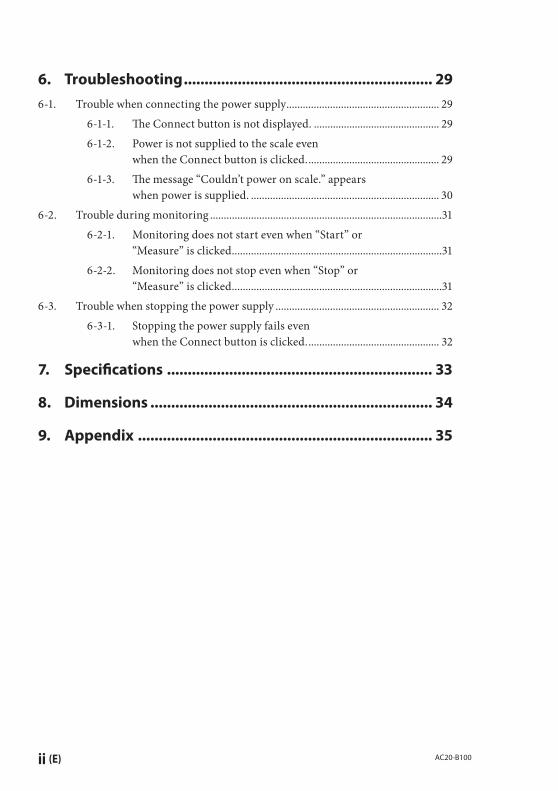
6. Troubleshooting ............................................................ 296-1. Trouble when connecting the power supply ........................................................ 29
6-1-1. Th e Connect button is not displayed. .............................................. 296-1-2. Power is not supplied to the scale even
when the Connect button is clicked. ................................................ 296-1-3. Th e message “Couldn’t power on scale.” appears
when power is supplied. ..................................................................... 306-2. Trouble during monitoring .....................................................................................31
6-2-1. Monitoring does not start even when “Start” or “Measure” is clicked.. ...........................................................................31
6-2-2. Monitoring does not stop even when “Stop” or “Measure” is clicked. ............................................................................31
6-3. Trouble when stopping the power supply ............................................................ 326-3-1. Stopping the power supply fails even
when the Connect button is clicked. ................................................ 32
7. Specifi cations ................................................................ 33
8. Dimensions .................................................................... 34
9. Appendix ....................................................................... 35

(E) 1AC20-B100
1. Outline
1-1. Introduction
Th e AC20-B100 is a monitoring tool used to perform scale failure analysis and to check scale operation aft er installing or replacing scales. Th is tool is used by connecting it to a computer to which the special soft ware Ver. 01.02.04*1 has been downloaded and a compatible scale.*1: Download the special software from the Magnescale website. This product is used to check
the scale failure status and installation status, and does not guarantee scale functions or performance. Refer to the respective instruction manual for the scale operation method.
1-2. Major functions and features of the software
Lissajous monitoringUse the monitoring function that matches the scale.• SR/RU Lissajous monitoring function• RS Lissajous monitoring function• SQ Lissajous monitoring function
1-3. Product confi guration
AC20-B100Soft ware MGS Monitoring System
(Download from the Magnescale website.)USB cable × 2 (accessory)Adaptor cable (sold separately)
CE35-02 (compatible controller: Mitsubishi Electric Corporation)
CE36-02 (compatible controller: FANUC Corporation)
CE37-02 (compatible controller: SIEMENS AG)Special cable SR77, SR87, and RU77 series require separate special cables. Contact our
sales representative.

2 (E) AC20-B100
2. Names and functions of each part
ENCODER Connector
AUX-POWER Connector
USB Connector
Name DescriptionENCODER Connector Connects to the scale using the adaptor cable (sold
separately)USB Connector Connects to the computer using the supplied USB cable.
AUX-POWER Connector Connects to the computer using the supplied USB cable to provide power when power supply to the scale is insuffi cient. Th is connector cannot be used for communication. (An external DC 5 V power supply adaptor can also be connected.)
(E) 3AC20-B100
3. System environment and setup
3-1. Compatible system environment
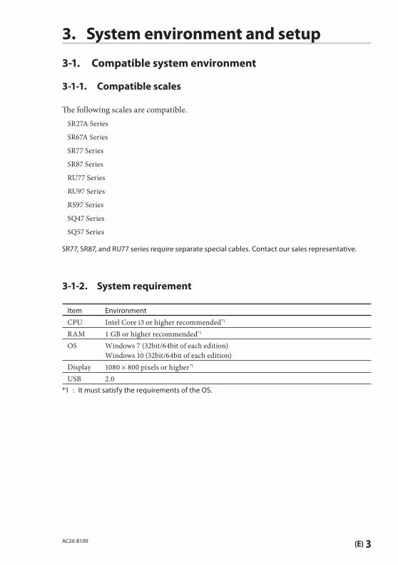
3-1-1. Compatible scales
Th e following scales are compatible.SR27A Series
SR67A Series
SR77 Series
SR87 Series
RU77 Series
RU97 Series
RS97 Series
SQ47 Series
SQ57 Series
SR77, SR87, and RU77 series require separate special cables. Contact our sales representative.
3-1-2. System requirement
Item Environment
CPU Intel Core i3 or higher recommended*1
RAM 1 GB or higher recommended*1
OS Windows 7 (32bit/64bit of each edition)Windows 10 (32bit/64bit of each edition)
Display 1080 × 800 pixels or higher*1
USB 2.0*1 : It must satisfy the requirements of the OS.
4 (E) AC20-B100
3-2. Software installationNote : If a diff erent version is already installed in the computer to be connected, be sure to
uninstall that version before performing software installation. (Refer to “3-4. Software uninstallation.”)
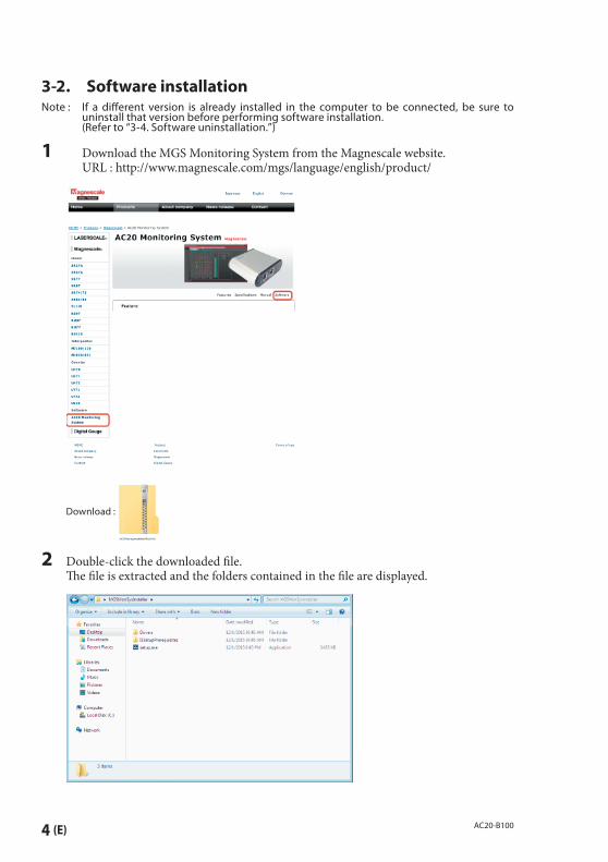
1 Download the MGS Monitoring System from the Magnescale website. URL : http://www.magnescale.com/mgs/language/english/product/
Download :
2 Double-click the downloaded fi le. Th e fi le is extracted and the folders contained in the fi le are displayed.
(E) 5AC20-B100
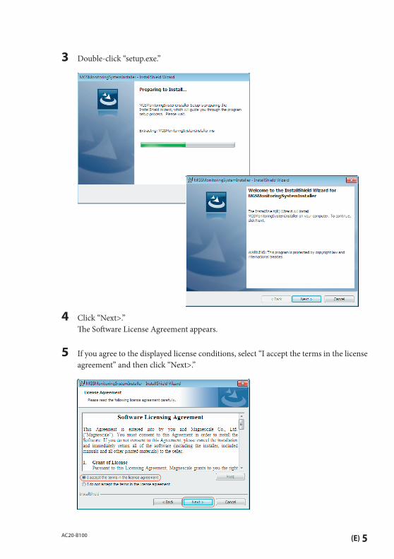
3 Double-click “setup.exe.”
4 Click “Next>.” Th e Soft ware License Agreement appears.
5 If you agree to the displayed license conditions, select “I accept the terms in the license agreement” and then click “Next>.”
6 (E) AC20-B100
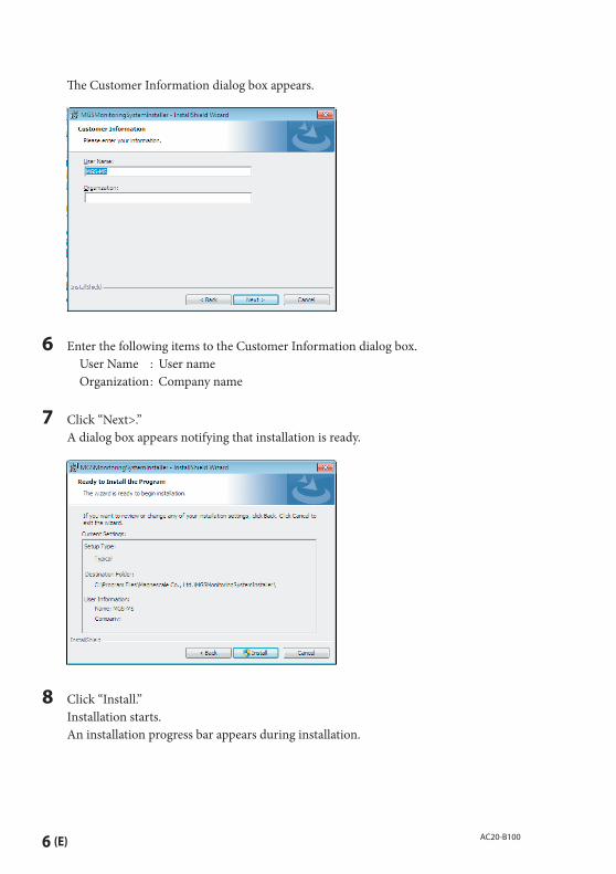
Th e Customer Information dialog box appears.
6 Enter the following items to the Customer Information dialog box. User Name : User name Organization : Company name
7 Click “Next>.” A dialog box appears notifying that installation is ready.
8 Click “Install.” Installation starts. An installation progress bar appears during installation.

(E) 7AC20-B100
9 When the dialog box shown below appears, click “Finish.”
10 Confi rm that the “MGSMonitoringSystem” icon appears on the computer desktop.
Th e installation is complete.
8 (E) AC20-B100
3-3. Driver installation
1 Connect the AC20-B100 to the computer using the supplied USB cable.
2 Click the “Drivers” folder contained in the fi le extracted in step 2 of section 3-2.
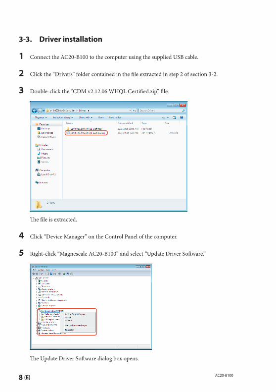
3 Double-click the “CDM v2.12.06 WHQL Certified.zip” fi le.
Th e fi le is extracted.
4 Click “Device Manager” on the Control Panel of the computer.
5 Right-click “Magnescale AC20-B100” and select “Update Driver Soft ware.”
Th e Update Driver Soft ware dialog box opens.
(E) 9AC20-B100
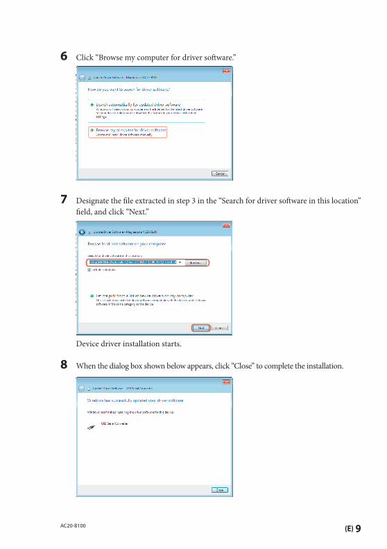
6 Click “Browse my computer for driver soft ware.”
7 Designate the fi le extracted in step 3 in the “Search for driver soft ware in this location” fi eld, and click “Next.”
Device driver installation starts.
8 When the dialog box shown below appears, click “Close” to complete the installation.

10 (E) AC20-B100
3-4. Software uninstallation
1 Click “Programs and Features” on the Control Panel of the computer.
2 Double-click “MGSMonitoringSystem” in the displayed list of soft ware.
Th e dialog box shown below appears.
3 Confi rm the message and click “Yes.”
An uninstallation progress bar appears during uninstallation. When “MGSMonitoringSystem” disappears from within “Programs and Features”,
uninstallation is complete.
(E) 11AC20-B100
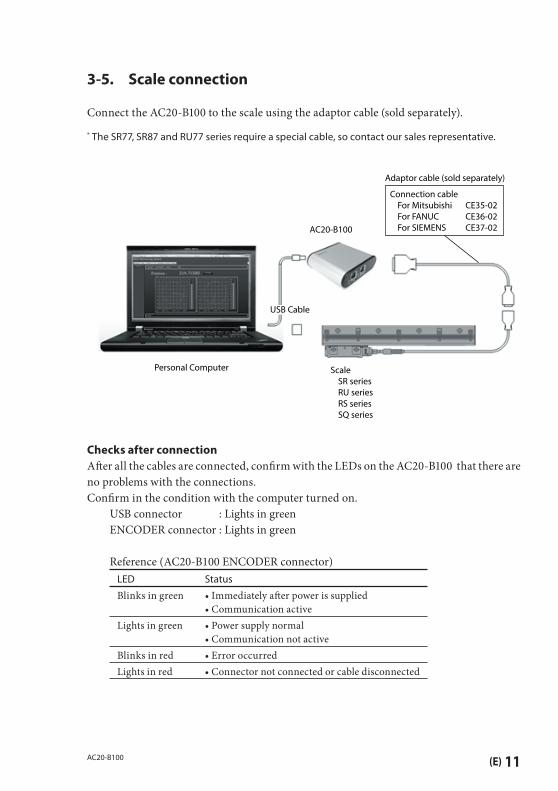
3-5. Scale connection
Connect the AC20-B100 to the scale using the adaptor cable (sold separately).
* The SR77, SR87 and RU77 series require a special cable, so contact our sales representative.
Personal Computer
USB Cable
AC20-B100
Adaptor cable (sold separately)
Scale SR series RU series RS series SQ series
Connection cable For Mitsubishi CE35-02 For FANUC CE36-02 For SIEMENS CE37-02
Checks after connectionAft er all the cables are connected, confi rm with the LEDs on the AC20-B100 that there are no problems with the connections.Confi rm in the condition with the computer turned on. USB connector : Lights in green ENCODER connector : Lights in green Reference (AC20-B100 ENCODER connector)
LED Status
Blinks in green • Immediately aft er power is supplied• Communication active
Lights in green • Power supply normal• Communication not active
Blinks in red • Error occurredLights in red • Connector not connected or cable disconnected
12 (E) AC20-B100
4. Starting up the software and supplying power to the scale
4-1. Starting up the software
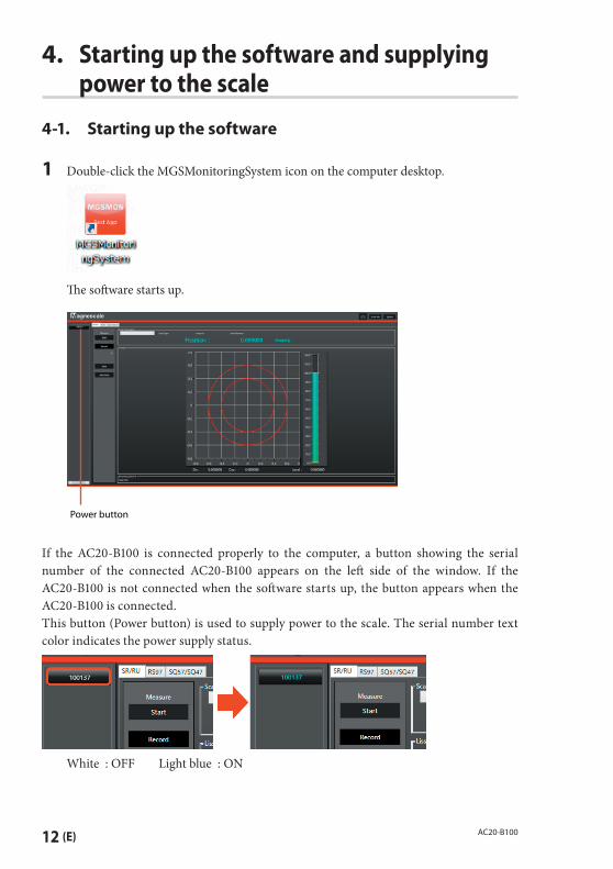
1 Double-click the MGSMonitoringSystem icon on the computer desktop.
Th e soft ware starts up.
Power button
If the AC20-B100 is connected properly to the computer, a button showing the serial number of the connected AC20-B100 appears on the left side of the window. If the AC20-B100 is not connected when the soft ware starts up, the button appears when the AC20-B100 is connected.This button (Power button) is used to supply power to the scale. The serial number text color indicates the power supply status.
White : OFF Light blue : ON
(E) 13AC20-B100
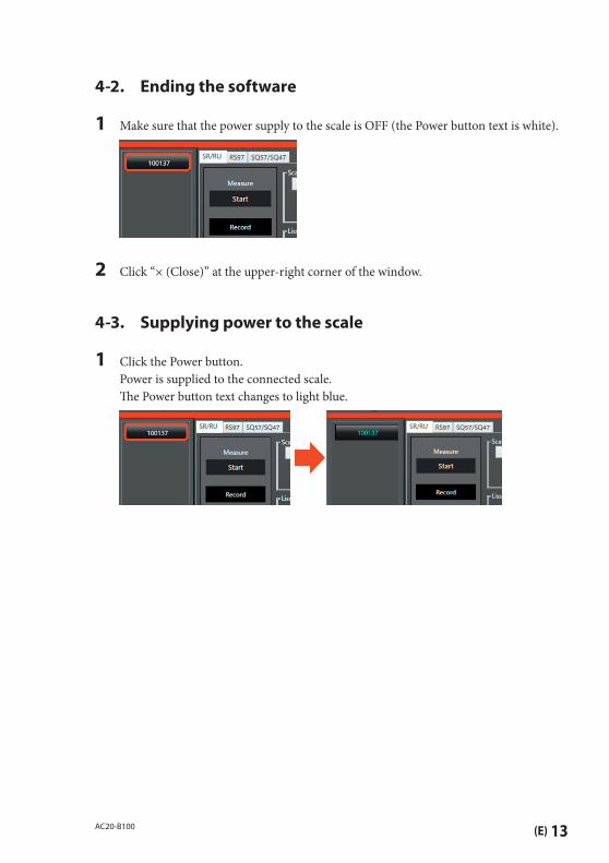
4-2. Ending the software
1 Make sure that the power supply to the scale is OFF (the Power button text is white).
2 Click “× (Close)” at the upper-right corner of the window.
4-3. Supplying power to the scale
1 Click the Power button. Power is supplied to the connected scale. Th e Power button text changes to light blue.
14 (E) AC20-B100
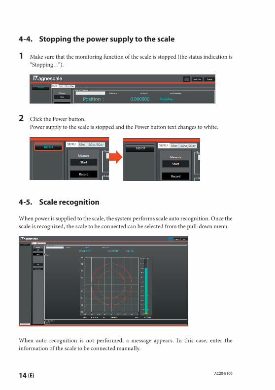
4-4. Stopping the power supply to the scale
1 Make sure that the monitoring function of the scale is stopped (the status indication is “Stopping…”).
2 Click the Power button. Power supply to the scale is stopped and the Power button text changes to white.
4-5. Scale recognition
When power is supplied to the scale, the system performs scale auto recognition. Once the scale is recognized, the scale to be connected can be selected from the pull-down menu.
When auto recognition is not performed, a message appears. In this case, enter the information of the scale to be connected manually.
(E) 15AC20-B100
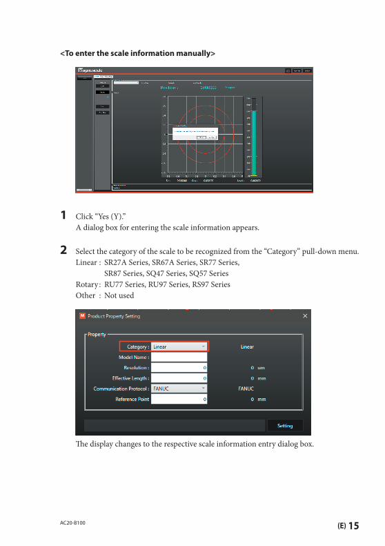
<To enter the scale information manually>
1 Click “Yes (Y).” A dialog box for entering the scale information appears.
2 Select the category of the scale to be recognized from the “Category” pull-down menu. Linear : SR27A Series, SR67A Series, SR77 Series,
SR87 Series, SQ47 Series, SQ57 Series Rotary : RU77 Series, RU97 Series, RS97 Series Other : Not used
Th e display changes to the respective scale information entry dialog box.

16 (E) AC20-B100
3 When “Linear” is selected Enter the scale information (Model Name, Resolution, Eff ective Length, Communication
Protocol, Reference Point), and click the “Setting” button.
(Example above) Category : Linear Model name : SQ57-032SAAX Resolution : 0.01 μm Eff ective length : 320 mm Communication protocol : FANUC Reference point : 160 mm (X : center)
Note: In case of a SQ47/SQ57 series scale, the resolution, eff ective length, supported communication protocol, and reference point are automatically entered when the scale name (Model Name) is entered. If the automatically entered contents are incorrect, correct the contents and then click the “Setting” button.
(E) 17AC20-B100
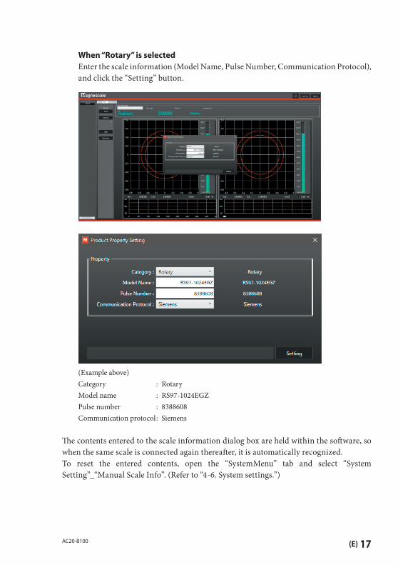
When “Rotary” is selectedEnter the scale information (Model Name, Pulse Number, Communication Protocol), and click the “Setting” button.
(Example above) Category : Rotary Model name : RS97-1024EGZ Pulse number : 8388608 Communication protocol : Siemens
Th e contents entered to the scale information dialog box are held within the soft ware, so when the same scale is connected again thereaft er, it is automatically recognized.To reset the entered contents, open the “SystemMenu” tab and select “System Setting”_“Manual Scale Info”. (Refer to “4-6. System settings.”)

18 (E) AC20-B100
4-6. System settings
Make the soft ware settings, such as the message language and the window display method. Th e contents set here are automatically saved when the soft ware is ended normally.
1 Make sure that power supply to the scale is stopped.
2 Click “System” at the upper-right corner of the soft ware window.
Open the “SystemMenu” tab to display the system settings window.
System InformationTh is displays the soft ware name and version and the internally held information.
System SettingLanguage : Selects the message language. (Japanese / English) Th e language selected here is displayed in “Current Culture.”Manual Scale Info : Resets all scale information entered manually during scale
recognition. Note that all saved manually entered information will be reset.

(E) 19AC20-B100
Application SettingWindow Mode : Selects the window display. (tab display / single windows)Default Module : Selects the functions to be displayed as standard when the soft ware
starts up.
SmartSCALE SettingABS Device ID : Selects the device to be connected to an absolute type scale (SQ47/
SQ57).INC Device ID : Not used.Check type : Select “Check” (the color changes to light blue) to display a manual
entry fi eld when the scale model name could not be automatically recognized. In the default condition, this is selected.
20 (E) AC20-B100
5. Monitoring Lissajous signals
5-1. Monitoring the Lissajous signal of SR27A/SR67A/SR87/SR77/RU77/RU97
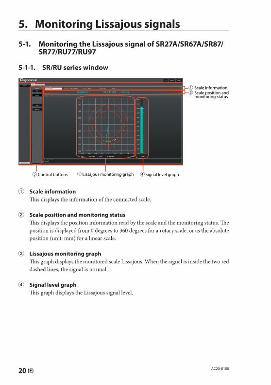
5-1-1. SR/RU series window
Lissajous monitoring graphControl buttons Signal level graph
Scale informationScale position and monitoring status
Scale information Th is displays the information of the connected scale.
Scale position and monitoring status Th is displays the position information read by the scale and the monitoring status. Th e
position is displayed from 0 degrees to 360 degrees for a rotary scale, or as the absolute position (unit: mm) for a linear scale.
Lissajous monitoring graph Th is graph displays the monitored scale Lissajous. When the signal is inside the two red
dashed lines, the signal is normal.
Signal level graph Th is graph displays the Lissajous signal level.

(E) 21AC20-B100
Control buttons
“Start/Stop” buttonTh is starts and stops monitoring. Th is button can be used when power is supplied to the scale and a scale is selected in the pull-down menu. Always stop monitoring before stopping the power supply to the scale.
“Record” buttonSelect this button (On: the button text is light blue) to record the monitored Lissajous data. Th e Lissajous data currently being monitored is accumulated.
“Save” buttonTh is saves the data accumulated using the “Record” button in a folder. Always stop monitoring before saving data.
“Data Clear” buttonTh is clears the data accumulated using the “Record” button and the Lissajous monitoring graph.
5-1-2. Starting and stopping monitoring
1 Click the “SR/RU” tab in the condition with the MGSMonitoringSystem started up. Th e window shown below appears.
2 Make sure that power is supplied to the scale (the Connect button text is light blue).

22 (E) AC20-B100
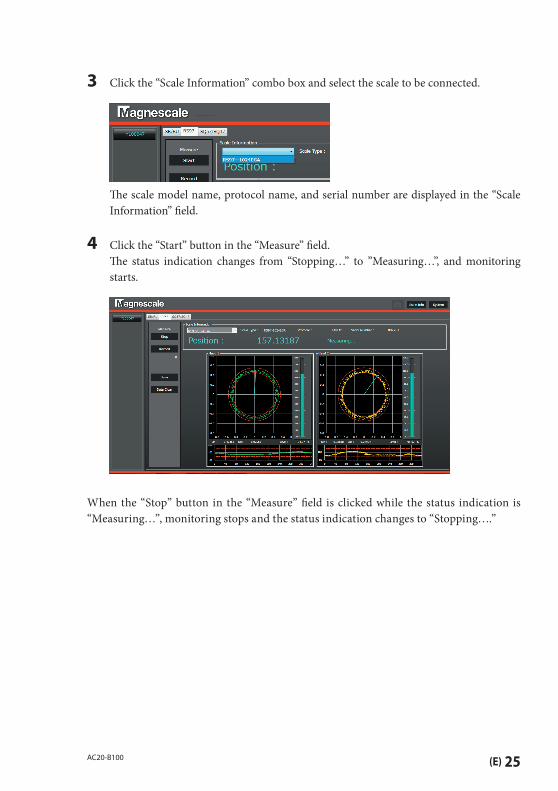
3 Click the “Scale Information” combo box and select the scale to be connected.
Th e scale model name, protocol name, and serial number are displayed in the “Scale
Information” fi eld.
4 Click the “Start” button in the “Measure” fi eld. Th e status indication changes from “Stopping…” to ”Measuring…”, and monitoring
starts.
When the “Stop” button in the “Measure” fi eld is clicked while the status indication is “Measuring…”, monitoring stops and the status indication changes to “Stopping….”
(E) 23AC20-B100
5-2. Monitoring the Lissajous signals of RS97
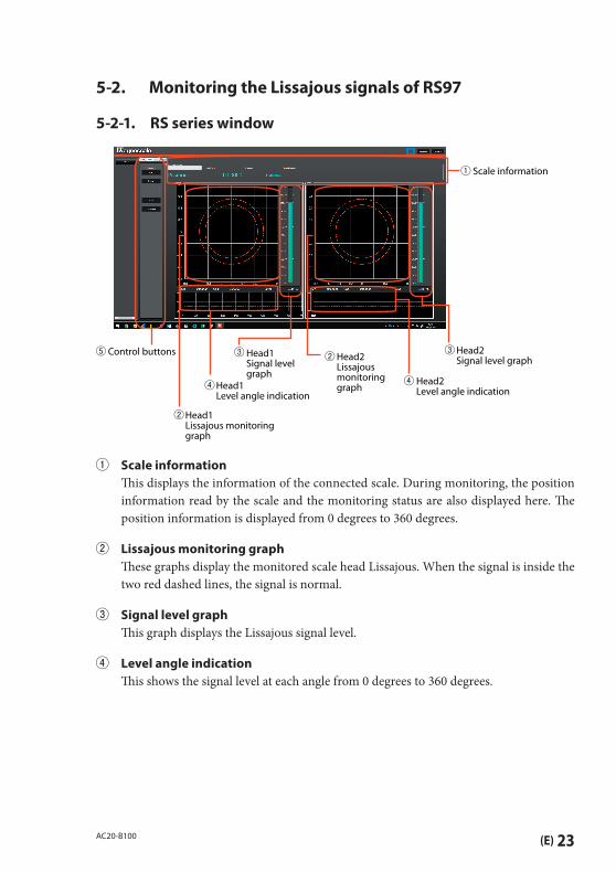
5-2-1. RS series window
Head1Level angle indication
Head1Lissajous monitoring graph
Head1 Signal level graph
Head2Signal level graph
Head2Level angle indication
Head2 Lissajous monitoring graph
Scale information
Control buttons
Scale information Th is displays the information of the connected scale. During monitoring, the position
information read by the scale and the monitoring status are also displayed here. Th e position information is displayed from 0 degrees to 360 degrees.
Lissajous monitoring graph Th ese graphs display the monitored scale head Lissajous. When the signal is inside the
two red dashed lines, the signal is normal.
Signal level graph Th is graph displays the Lissajous signal level.
Level angle indication Th is shows the signal level at each angle from 0 degrees to 360 degrees.

24 (E) AC20-B100
Control buttons
“Start/Stop” buttonTh is starts and stops monitoring. Th is button can be used when power is supplied to the scale and a scale is selected in the pull-down menu. Always stop monitoring before stopping the power supply to the scale.
“Record” buttonSelect this button (On: the button text is light blue) to record the monitored Lissajous data. Th e Lissajous data currently being monitored is accumulated.
“Save” buttonTh is saves the data accumulated using the “Record” button in a folder. Always stop monitoring before saving data.
“Clear Data” buttonTh is clears the data accumulated using the “Record” button and the Lissajous monitoring graph.
5-2-2. Starting and stopping monitoring
1 Click the “RS97” tab in the condition with the MGSMonitoringSystem started up. Th e window shown below appears.
2 Make sure that power is supplied to the scale (the Connect button text is light blue).
(E) 25AC20-B100
3 Click the “Scale Information” combo box and select the scale to be connected.
Th e scale model name, protocol name, and serial number are displayed in the “Scale
Information” fi eld.
4 Click the “Start” button in the “Measure” fi eld. Th e status indication changes from “Stopping…” to ”Measuring…”, and monitoring
starts.
When the “Stop” button in the “Measure” fi eld is clicked while the status indication is “Measuring…”, monitoring stops and the status indication changes to “Stopping….”

26 (E) AC20-B100
5-3. Monitoring the Lissajous signals of SQ57/SQ47
5-3-1. SQ series window
Lissajous monitoring graphControl buttons
Scale alarm
Scale position and monitoring status
Adjustment status
Position dependent adjustment level graph
Signal level graph
Scale position and monitoring status Th is displays the position information read by the scale and the monitoring status. Th e
position is displayed as the absolute position (unit: mm).
Lissajous monitoring graph Th is graph displays the monitored scale Lissajous. When the signal is inside the two red
dashed lines, the signal is normal.
Signal level graph Th is graph displays the Lissajous signal level.
Position dependent adjustment level graph Th is displays the scale and sensor adjustment levels* at the positions passed by the head
using diff erent colors. Th e adjustment levels are constantly updated. Once drawn, the graph remains even aft er communication with the AC20-B100 stops, but disappears and a new graph is drawn when scale monitoring is restarted.* These adjustment levels change according to the clearance between the scale and the
head.
Green : Recommended positionRed : Outside recommended range When red is displayed, recheck the head and scale mounting positions.
Clearance display range: Scale effective length ±15 mm
(E) 27AC20-B100
Adjustment status Th is displays the current scale and head adjustment status. Green (Good) : Recommended position Red (Warning) : Outside recommended range When red (Warning) is displayed, recheck the head and scale mounting positions.
Scale alarm
Alarm Cause Countermeasure
SPEED ERROR Over-speed • Check the scale feed rate.SIGNAL LEVEL ERROR Low signal level • Check the head and scale mounting
positions.
• Check whether the scale or head are damaged.
OTHER ERROR Other error
Control buttons
“Record” buttonClick this button to record the monitored Lissajous data. Th e Lissajous data currently being monitored is accumulated. Th e button is light blue while data accumulation is underway.
“Save” buttonTh is saves the data accumulated using the “Record” button in a folder. Always stop monitoring before saving data.
“Data Clear” buttonTh is clears the data accumulated using the “Record” button and the Lissajous monitoring graph.
28 (E) AC20-B100
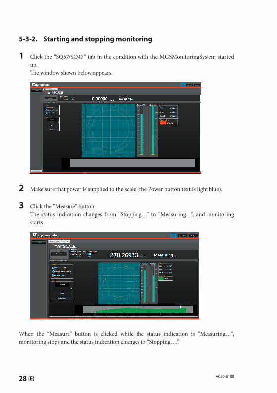
5-3-2. Starting and stopping monitoring
1 Click the “SQ57/SQ47” tab in the condition with the MGSMonitoringSystem started up.
Th e window shown below appears.
2 Make sure that power is supplied to the scale (the Power button text is light blue).
3 Click the “Measure” button. Th e status indication changes from “Stopping…” to ”Measuring…”, and monitoring
starts.
When the “Measure” button is clicked while the status indication is “Measuring…”, monitoring stops and the status indication changes to “Stopping….”
(E) 29AC20-B100
6. Troubleshooting
6-1. Trouble when connecting the power supply
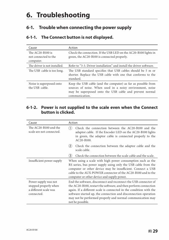
6-1-1. The Connect button is not displayed.
Cause Action
Th e AC20-B100 is not connected to the computer.
Check the connection. If the USB LED on the AC20-B100 lights in green, the AC20-B100 is connected properly.
Th e driver is not installed. Refer to ”3-3. Driver installation” and install the driver soft ware.Th e USB cable is too long. Th e USB standard specifi es that USB cables should be 5 m or
shorter. Replace the USB cable with one that conforms to the standard.
Noise is superposed onto the USB cable.
Keep the USB cable (and the computer) as far as possible from sources of noise. When used in a noisy environment, noise may be superposed onto the USB cable and prevent normal communication.
6-1-2. Power is not supplied to the scale even when the Connect button is clicked.
Cause Action
Th e AC20-B100 and the scale are not connected.
Check the connection between the AC20-B100 and the adaptor cable. If the Encoder LED on the AC20-B100 lights in green, the adaptor cable is connected properly to the AC20-B100.
Check the connection between the adaptor cable and the scale cable.
Check the connection between the scale cable and the scale.Insuffi cient power supply When using a scale with high power consumption such as the
RS series, bus power supply using only the USB cable from the computer or other device may be insuffi cient. Connect a USB cable to the AUX-POWER connector of the AC20-B100 and to the computer or other device and supply power.
Power supply was not stopped properly when a diff erent scale was connected.
End the soft ware, disconnect and reconnect the USB connector of the AC20-B100, restart the soft ware, and then perform connection again. If a diff erent scale is connected in the condition with the soft ware started up, the connection and disconnection operation may not be performed properly and normal communication may not be possible.
30 (E) AC20-B100
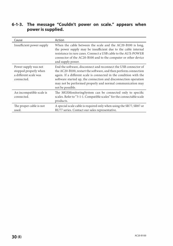
6-1-3. The message “Couldn't power on scale.” appears when power is supplied.
Cause Action
Insuffi cient power supply When the cable between the scale and the AC20-B100 is long, the power supply may be insuffi cient due to the cable internal resistance in rare cases. Connect a USB cable to the AUX-POWER connector of the AC20-B100 and to the computer or other device and supply power.
Power supply was not stopped properly when a diff erent scale was connected.
End the soft ware, disconnect and reconnect the USB connector of the AC20-B100, restart the soft ware, and then perform connection again. If a diff erent scale is connected in the condition with the soft ware started up, the connection and disconnection operation may not be performed properly and normal communication may not be possible.
An incompatible scale is connected.
Th e MGSMonitoringSystem can be connected only to specifi c scales. Refer to “3-1-1. Compatible scales” for the connectable scale products.
Th e proper cable is not used.
A special scale cable is required only when using the SR77, SR87 or RU77 series. Contact our sales representative.
(E) 31AC20-B100
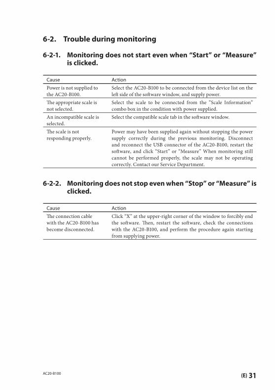
6-2. Trouble during monitoring
6-2-1. Monitoring does not start even when “Start” or “Measure” is clicked.
Cause Action
Power is not supplied to the AC20-B100.
Select the AC20-B100 to be connected from the device list on the left side of the soft ware window, and supply power.
Th e appropriate scale is not selected.
Select the scale to be connected from the ”Scale Information” combo box in the condition with power supplied.
An incompatible scale is selected.
Select the compatible scale tab in the soft ware window.
Th e scale is not responding properly.
Power may have been supplied again without stopping the power supply correctly during the previous monitoring. Disconnect and reconnect the USB connector of the AC20-B100, restart the soft ware, and click “Start” or “Measure” When monitoring still cannot be performed properly, the scale may not be operating correctly. Contact our Service Department.
6-2-2. Monitoring does not stop even when “Stop” or “Measure” is clicked.
Cause Action
Th e connection cable with the AC20-B100 has become disconnected.
Click “X” at the upper-right corner of the window to forcibly end the soft ware. Th en, restart the soft ware, check the connections with the AC20-B100, and perform the procedure again starting from supplying power.
32 (E) AC20-B100
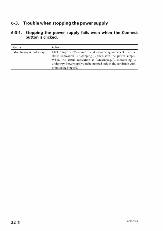
6-3. Trouble when stopping the power supply
6-3-1. Stopping the power supply fails even when the Connect button is clicked.
Cause Action
Monitoring is underway. Click “Stop” or “Measure” to end monitoring and check that the status indication is “Stopping...”, then stop the power supply. When the status indication is “Measuring...”, monitoring is underway. Power supply can be stopped only in the condition with monitoring stopped.
(E) 33AC20-B100
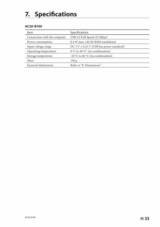
7. Specifi cations
AC20-B100
Item Specifi cations
Connection with the computer USB 2.0 Full Speed (12 Mbps)Power consumption 0.4 W max. (AC20-B100 standalone)Input voltage range DC 5 V ± 0.25 V (USB bus power standard)Operating temperature 0 ºC to 40 ºC (no condensation)Storage temperature ‒10 ºC to 60 ºC (no condensation)Mass 150 gExternal dimensions Refer to “8. Dimensions”
34 (E) AC20-B100
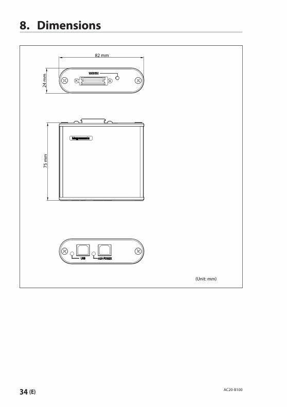
8. Dimensions
82 mm
(Unit: mm)
24 m
m75
mm
(E) 35AC20-B100
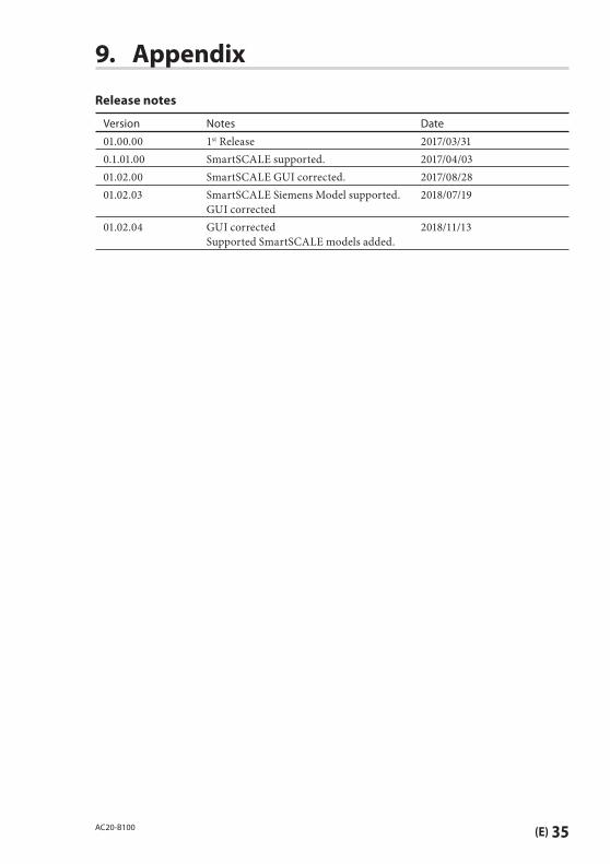
9. Appendix
Release notes
Version Notes Date
01.00.00 1st Release 2017/03/310.1.01.00 SmartSCALE supported. 2017/04/0301.02.00 SmartSCALE GUI corrected. 2017/08/2801.02.03 SmartSCALE Siemens Model supported.
GUI corrected2018/07/19
01.02.04 GUI correctedSupported SmartSCALE models added.
2018/11/13

36 (E) AC20-B100

このマニュアルに記載されている事柄の著作権は当社にあり、説明内容は機器購入者の使用を目的としています。したがって、当社の許可なしに無断で複写したり、説明内容 ( 操作、保守など ) と異なる目的で本マニュアルを使用することを禁止します。
The mater ia l contained in this manual consists of information that is the property of Magnescale Co., Ltd. and is intended solely for use by the purchasers of the equipment described in this manual.Magnescale Co. , Ltd. expressly prohibits the duplication of any portion of this manual or the use thereof for any purpose other than the operation or maintenance of the equipment described in this manual without the express written permission of Magnescale Co., Ltd.
Le matériel contenu dans ce manuel consiste en informations qui sont la propriété de Magnescale Co., Ltd. et sont destinées exclusivement à l ' u s a g e d e s a c q u é r e u r s d e l'équipement décrit dans ce manuel.M a g n e s c a l e C o. , L t d . i n t e r d i t formellement la copie de quelque partie que ce soit de ce manuel ou son emploi pour tout autre but que des opérations ou entretiens de l 'équipement à moins d'une permission écrite de Magnescale Co., Ltd.
Die in dieser Anleitung enthaltenen I n fo r m a t i o n e n s i n d E i g e n t u m vo n M a g n e s c a l e Co. , L t d . u n d s i n d a u s s c h l i e ß l i c h f ü r d e n Gebrauch durch den Käufer der in dieser Anleitung beschriebenen Ausrüstung bestimmt.Magnescale Co. , Ltd. untersagt ausdrücklich die Vervielfältigung jeglicher Teile dieser Anleitung oder den Gebrauch derselben für irgendeinen anderen Zweck als die Bedienung oder Wartung der in dieser Anleitung beschriebenen Ausrüstung ohne ausdrückliche s c h r i f t l i c h e E r l a u b n i s v o n Magnescale Co., Ltd.

AC20-B1002-A02-396-1B
2019.4Printed in Japan
©2017 Magnescale Co., Ltd.
45 Suzukawa, Isehara-shi, Kanagawa 259-1146, Japan
日本からの輸出時における注意本製品 ( および技術 ) は輸出令別表第 1の 16 の項 ( 外為令別表 16 の項 ) に該当します。キャッチオール規制による経済産業省の許可要否につきましては、輸出者様にてご確認ください。
For foreign customersNote: This product (or technology) may be restricted by the government in your country. Please make sure that end-use, end user and country of destination of this product do not violate your local government regulation.