ace roto-mold elliptical tanks
TRANSCRIPT


800-433-3579
w9898 jackson rd near Deerfield, WI
A. Contree Sprayer & Equip.CO LLCW9898 Jackson Rd, Beaver Dam, WI (800) 433-3579
Contree Sprayer and Equipment Your Custom Sprayer Specialists
Contree Sprayer and Equipment has over 50 years of experience designing, building, and servicing spraying equipment. We provide custom built sprayers for all types of applications from simple lawn units to large field sprayers. Contree carries a complete line of pumps, parts, and accessories to fit most any sprayer. Orders called in my 1:00 pm will be shipped the same day for in-stock items. We can update your old sprayer to present day standards with equipment such as boom, tank, pump, spray control, foamer, hose, and nozzles.
Contree Sprayer and Equipment is continually expanding and seeking the latest products coming to market to serve you better. Out catalogue is just a sampling of the products and venders we have to offer to you as a customer. We have included the most popular equipment and parts breakdowns to assist you in your search. If you are looking for a product not listed in our catalogue we can most likely get it for you! If you have questions about an old unit, a quote for a new unit, parts, or other accessories there are several ways to contact us:
WWW.CONTREE.COM [email protected] Local: (920) 356-0121 Fax: (920) 356-0228
Toll Free: (800) 433-3579
Located in beautiful Beaver Dam, WI 53916 at W9898 Jackson Road
30 Minutes Northeast of Madison on Hwy 151
30 Minutes Southwest of Fond du Lac on Hwy 151
1 hour Northwest of Milwaukee via US 41 to Hwy 33 to Hwy 151
Table of ConTenTs
UNITS 4-13 TANKS 14-33
(Add’l Tank Fittings: See Manifolds) PUMPS & EQUIPMENT 34-75
HYPRO 34-54 Roller 34-36 Centrifugal 37-40 Diaphragm 41-54 SHURflo 54-55
ACE 56-63 PTOC Centrifugal 56-58 Centrifugal 59-62 Gas Motor Centrifugal 63
BANJO 64-73 1½”-2” Poly Centrifugal 64-65 1½” Cast Centrifugal 69 2” Cast Centrifugal 66-70, 72 3” Cast Centrifugal 68, 71-73
UDOR 74 DELAVAN 74 CDS-JOHN BLUE 75-79
Piston/NGP 75-77 Diaphragm 78 VisaGauge II/Flow Monitors 78-79
MICRO-TRAK 80 WILGER 81 BACKPACK & HANDHELD 82 RAVEN 83-95
Field Computers & Steering 83-85 Boom Control 85-86, 92 SCS Controls 87-89 Guidance 80-92 Flow Controls 93-95
VALVES 95-110 (Add’l Valves: Manifolds, Raven)
Electric 95-98, 101, 103-106 Poly 99, 101 Poly Bolted 99-101 Manual 107-108 Stainless & Brass 95, 102, 107-108, 110
MANIFOLDS 111-123 Valves
Electric 111-113 Poly Bolted 114-116 Stainless 114-116 Dry Disconnect 116
Fittings Stainless 117-121 Inductor 116 Sweeps 117 Poly 117-120 Strainer 121-122 Tank Fittings 123
GAUGES 124-126 FITTINGS 127-137
(Add’l Fittings: Manifolds, Boom Equip.)
Poly 127-134 Stainless 133, 135, 137 Strainers 134-137
HOSE 138-140 REELS 141-145
Cox 141-143 Hannay 143-145
HANDGUNS 146-151 BOOM EQUIPMENT 152-200
(Valves See: Valves, Manifolds, Raven) Field Sprayers 152 Booms 152-153 Nozzles 154-178 Tip Strainer 179 Boom Clamps 178, 185, 189 Spray Tips 181-192 Nozzle Bodies 193-197 Boom Accessories 196-197 Line Strainer 198 Boominator 199-200
ACCESSORIES 201-202 Thread Sealant 201 Stainless Clamps 119, 201-202 Cable Ties 202 Hose Cutter 202
GENERAL SALES POLICY 203

UNITS
*Warranty information available upon request
All units can be customized to your specifications!!!4 800-433-3579
3-Point Sprayer
Features:*55 (shown) or 110 gallon poly tank, saddle mounts with straps, bottom suction for complete drainage. Three Year Warranty.*Heavy duty welded steel frame. Frame is primed and painted.*Roller pump with steel 1-3/8” quick pin coupler for 540 RPM PTO. Hose saver connections. 9.1 GPM max and 150 PSI max. Two year warranty.*Tank valve and suction strainer.*0 to 150 PSI liquid filled gauge and pressure control system on frame mount.*Adjustable boom height on frame*Sprayer boom with 20” nozzle spacing, flat fan nozzles, and diaphragm check valves to prevent dripping.*Other features available upon request.*Unit tested and ready to be used!
Options to choose from:*Breakaway, spring loaded sprayer booms*Boom control valves*Handgun and hose for spot spraying

UNITS
*Warranty information available upon request
All units can be customized to your specifications!!! [email protected]
30 Gallon Pest Control Sprayer
Features:*30 gallon poly tank with bottom suction for complete drainage. Three Year Warranty.*Heavy duty welded steel frame. Frame is primed and painted. 24”W x 40”L x 34”H *Diaphragm pump, 6 gpm max and 275 psi max with gear reduction mounted directly to engine. No visible moving parts. Two year warranty.*Electric Rewind Hose Reel with a one year warranty. 12V DC rewind with push button switch, 40 Amp circuit breaker, and 20 foot power cable to attach to vehicle battery.*Tank valve and suction strainer.*0 to 300 PSI liquid filled gauge and pressure control system.*100’ of 3/8” handgun hose. 600 psi working pressure.*Honda GX160 engine, overhead valve for a cleaner operation, equipped with a low-oil sensor to prevent engine damage. One year Honda warranty.*Hose swivel between handgun and handgun hose to prevent kinking.*Green Garde Handgun with adjustable nozzle form solid stream to hollow cone*Other features available upon request.*Unit tested and ready to be used!

UNITS
*Warranty information available upon request
All units can be customized to your specifications!!!6 800-433-3579
Standard Skid Sprayer
Features:*Available in 100, 200 (shown), and 300 gallon poly tank with agitation*Top mounted suction tube means no bottom fittings to leak over time*Honda GX160 engine, overhead valve for a cleaner operation, equipped with alow-oil sensor to prevent engine damage. One year Honda warranty.*Electric rewind reel*Handgun hose (different length & size options available)*Lawn gun with 1.5 GPM nozzle*Robust frame with fork lift channels*Suction strainer with 30 mesh screen*Pressure control unit with liquid filled gauge*Hose swivel to prevent kinks at handgun*Unit tested and ready to use!
Options to chose from:Pump- *Hypro D252 with gear reduction, 6.5 GPM at 290 PSI Max
*Hypro D30 with gear reduction, 9.6 GPM at 580 PSI Max*Hypro D403 with gear reduction, 9.9 GPM at 580 PSI Max
Hose Reels-*Cox or Hannay with electric rewind wiring harness to run off vehicle power supply

UNITS
*Warranty information available upon request
All units can be customized to your specifications!!! [email protected]
Features:*300 gallon poly tank with agitation*Top mounted suction tube means no bottom fittings to leak over time*Honda GX160 engine, overhead valve for a cleaner operation, equipped with alow-oil sensor to prevent engine damage. One year Honda warranty.*Electric rewind reel*Handgun hose (different length & size options available)*Lawn gun with 1.5 GPM nozzle*Robust frame with fork lift channels*Suction strainer with 30 mesh screen*Pressure control unit with liquid filled gauge*Hose swivel to prevent kinks at handgun*Unit tested and ready to use!
Options to chose from:Pump- *Hypro D252 with gear reduction, 6.5 GPM at 290 PSI Max
*Hypro D30 with gear reduction, 9.6 GPM at 580 PSI Max*Hypro D403 with gear reduction, 9.9 GPM at 580 PSI Max
Hose Reels-*Cox or Hannay with electric rewind wiring harness to run off vehicle power supply
“Turfmaster” Pick-Up Bed Sprayer

UNITS
*Warranty information available upon request
All units can be customized to your specifications!!!8 800-433-3579
Features:*Available in 205 and 305 (shown) gallon poly tank with agitation*Top mounted suction tube means no bottom fittings to leak over time*Honda GX160 engine, overhead valve for a cleaner operation, equipped with alow-oil sensor to prevent engine damage. One year Honda warranty.*Electric rewind reel*Handgun hose (different length & size options available)*Lawn gun with 1.5 GPM nozzle*Robust frame with fork lift channels*Suction strainer with 30 mesh screen*Pressure control unit with liquid filled gauge*Hose swivel to prevent kinks at handgun*Unit tested and ready to use!
Options to chose from:Pump- *Hypro D252 with gear reduction, 6.5 GPM at 290 PSI Max
*Hypro D30 with gear reduction, 9.6 GPM at 580 PSI Max*Hypro D403 with gear reduction, 9.9 GPM at 580 PSI Max
Hose Reels-*Cox or Hannay with electric rewind wiring harness to run off vehicle power supply
“View-Saver” Pick-Up Bed Sprayer
Bottom suction available
Top Suction

UNITS
*Warranty information available upon request
All units can be customized to your specifications!!! [email protected]
Features:*Available in 100 and 200 gallon poly tank with agitation*Top mounted suction tube means no bottom fittings to leak over time*Honda GX160 engine, overhead valve for a cleaner operation, equipped with alow-oil sensor to prevent engine damage. One year Honda warranty.*Electric rewind reel*Handgun hose (different length & size options available)*Lawn gun with 1.5 GPM nozzle*Robust frame with fork lift channels*Suction strainer with 30 mesh screen*Pressure control unit with liquid filled gauge*Hose swivel to prevent kinks at handgun*Unit tested and ready to use!
Options to chose from:Pump- *Hypro D252 with gear reduction, 6.5 GPM at 290 PSI Max
*Hypro D30 with gear reduction, 9.6 GPM at 580 PSI Max*Hypro D403 with gear reduction, 9.9 GPM at 580 PSI Max
Hose Reels-*Cox or Hannay with electric rewind wiring harness to run off vehicle power supply
“Space-Saver” Pick-Up Bed Sprayer

UNITS
*Warranty information available upon request
All units can be customized to your specifications!!!10 800-433-3579
Nurse Trailers
Features:*Available in 1005, 1065, and 1300 gallon poly leg tank*Main Frame 2 x 6 channel*14,000 G.V.W.R*7,000 lbs axles with slipper spring*5,000 lbs top wind jack*Adjustable height clevis hitch with safety chains*Load range “E” tires for road use (Ribbed implement tires available)*Steel hoops with hose hangers*Poly Transfer pump with engine*Mounting platform for pump body*Unit tested and ready to use!
Options to chose from:*Work step*Additional plumbing kits*Work deck
1005 Gallon Trailer
1065 Gallon Trailer with Optional Step
1300 Gallon Trailer with Optional Deck

UNITS
*Warranty information available upon request
All units can be customized to your specifications!!! [email protected]
Trailer Sprayers
Features:*Available in 55 and 100 gallon poly tank with bottom suction for complete drainage. 3 Year Warranty.*Heavy duty welded steel frame. Frame is primed and painted. *Diaphragm Pump with gear reduction mounted directly to engine. No visible moving parts. 9.5 GPM max and 540 PSI max. -or- Centrifugal pump mounted directly to engine. No visible moving parts. 120 GPM max and 100 PSI max. Two year warranty on ‘Pump and Engine’. (12 VDC Electric and other pumps available)
*Available Electric Rewind Hose Reel with a one year warranty. 12V DC rewind with push button switch, 40 Amp circuit breaker, and 20 foot power cable to attach to vehicle battery. (manual rewind shown)
*Tank valve and suction strainer.*Liquid filled gauge and pressure control system.*100’ of 3/8” handgun hose. 600 psi working pressure.*Honda GX160 engine, overhead valve for a cleaner operation, equipped with alow-oil sensor to prevent engine damage. One year Honda warranty.*Hose swivel between handgun and handgun hose to prevent kinking.*Green Garde Handgun with adjustable nozzle from solid stream to hollow cone.*Sprayer boom with 20” nozzle spacing, Flat fan nozzles, and diaphragm check valves to prevent drip-ping (available, not shown).*Other features available upon request.*Unit tested and ready to be used!
Options to choose from:*Breakaway, spring loaded sprayer booms*Boom control valves*High pressure adjustable gun (shown, optional) or low pressure lawn gun
110 Gallon Sprayer
55 Gallon Sprayer

UNITS
*Warranty information available upon request
All units can be customized to your specifications!!!12 800-433-3579
Features:*24 gallon ATV tank specifically designed to have a lower center of gravity for handling and safety*Twin sumps allow for complete drainage of product*Plumbing & control valves mounted directly to tank for easy removal of sprayer from seat*Trigger style handgun, 12’ of hose, in-line strainer, and mainline valve
Options:Model 500 EZSS-
*Tank & handgun with Shurflo 1.4 gpm 12V pump with one on/off controlModel 500 EZ12-
*Features handgun and 12’ of hose, 3 section breakaway boom and a Shurflo 4.0 gpm 12V pump with one on/off control
Model 500 EZBB-*Features handgun and 12’ of hose, two boomless nozzles and a Shurflo 4.0 gpm 12V pump with two on/off control
Model 500 EZBB12-*Features handgun and 12’ of hose, 3 section breakaway boom, two boomless nozzles and a Shurflo 4.0 gpm 12V pump with two on/off control
ATV E-Z Rider Sprayer

UNITS
*Warranty information available upon request
All units can be customized to your specifications!!! [email protected]
Features:*Available in 50, 68, and 110 gallon horizontal tank maximizes bed area while keeping low center of gravity*Top mounted suction tube means no bottom fittings to leak over time*Honda GX160 engine, overhead valve for a cleaner operation, equipped with alow-oil sensor to prevent engine damage. One year Honda warranty.*Manual rewind reel*Handgun hose (different length & size options available)*High pressure handgun*Compact frame with fork lift channels*Suction strainer with 30 mesh screen*Pressure control unit with liquid filled gauge*Hose swivel to prevent kinks at handgun*Unit tested and ready to use!
Options:Pump-
*Hypro D30 with gear reduction, 9.6 GPM at 580 PSI Max*Hypro D252 with gear reduction, 6.5 GPM at 290 PSI Max
Hose Reels-*Cox electric rewind reel with wiring harness to connect to vehicle power supply*Hannay electric rewind reel with wiring harness to connect to vehicle power supply
UTV Low Profile Burn Unit
68 Gallon Shown

TANKS
14 800-433-3579
Ace Roto-Mold Poly Vertical Round Top Storage Tanks
Dome Top tanks are free standing with a flat bottom for indoor or outdoor installations. Ace Roto-Mold Vertical Tanks conform to the requirements of NSF/ANSI Standard 61.
Tanks are manufactured from medium- or high-density polyethylene with U.V. inhibitors. Tank walls are translucent for level viewing and equipped with gallon indicators.
Model Number
Capacity (Gal)
Spec. Grav.
Wt. (lbs)
Dimensions (D x H) Lid Fitting Model Number Capacity
(Gal)Spec. Grav.
Wt. (lbs)
Dimensions (D x H) Lid Fitting
VT0010-12 10 2 9 12 x 25 8” 3/4” VT2000-64 2,000 1.7 465 64 x 156 16” 2”VT0020-16 20 2 13 16 x 28 8” 3/4” VT2000-90 2,000 1.7 375 90 x 84 16” 2”VT0025-18 25 2 12 18 x 30 5” 3/4” VT2050-86 2,050 1.7 402 86 x 93 16” 2”VT0040-18 40 2 17 18 x 43 5” 3/4” VT2150-102 2,150 1.7 417 102 x 71 16” 2”VT0055-20 55 2 22 20 x 47 5” 1” VT2500-90 2,500 1.7 420 90 x 103 16” 2”VT0065-23 65 2 25 23 x 42 5” 1” VT3000-90 3,000 1.7 550 90 x 120 16” 2”VT0110-32 110 2 40 32 x 41 5” 2” (Top) VT3100-102* 3,100 1.7 550 102 x 103 16” 2”VT0135-23 135 2 47 23 x 82 16” 1” VT3400-102* 3,400 1.7 585 102 x 107 16” 2”VT0300-42 300 2 73 42 x 55 8” 2” VT4000-96* 4,000 1.7 900 96 x 140 16” 2”VT0405-52 405 2 90 52 x 48 8” 2” VT4200-96* 4,200 1.7 950 96 x 148 16” 2”VT0425-42 425 2 101 42 x 75 8” 2” VT5000-102* 5,000 1.7 1302 102 X 156 16” 3”VT0505-46 505 2 118 46 x 80 16” 2” VT5150-102* 5,150 1.7 1352 102 x 161 16” 3”VT0550-52 550 2 116 52 x 66 8” 2” VT6250-102* 6,250 1.7 1552 102 x 194 16” 3”VT0600-46 600 2 130 46 x 91 16” 2” VT6500-120* 6,500 1.7 1502 120 x 152 16” 3”VT0625-64 625 2 100 64 x 50 8” 2” VT7000-142* 7,000 1.7 1752 142 x 125 16” 3”VT0800-46 800 1.7 175 46 x 118 16” 2” VT7800-120* 7,800 1.7 1902 120 x 176 16” 3”VT0900-46 900 1.7 220 46 x 132 16” 2” VT8000-120* 8,000 1.7 1932 120 x 180 16” 3”VT1000-64 1,000 1.7 250 64 x 81 16” 2” VT9150-120* 9,150 1.7 2202 120 x 203 16” 3”VT1050-86 1,050 1.7 190 86 x 54 16” 2” VT9500-120* 9,500 1.7 2352 120 x 213 16” 3”VT1200-64 1,200 1.7 275 64 x 97 16” 2” VT10500-2500* 10,500 1.6 2502 142 x 177 16” 3”VT1350-86 1,350 1.7 228 86 x 65 16” 2” VT10500-2800* 10,500 1.8 2802 142 x 177 16” 3”VT1500-64 1,500 1.7 335 64 x 115 16” 2” VT12500-142* 12,500 1.7 3402 142 x 208 16” 3”
VT1500-86 1,500 1.7 250 86 x 69 16” 2” ~Syphon tube included with tanks 300 gallons or greater
VT1525-64 1,525 1.7 350 64 x 122 16” 2” *Indicated heavy duty fitting
VT1650-86 1,650 1.7 276 86 x 74 16” 2” ~Tanks available without fittings preinstalled

TANKS
Ace Roto-Mold Poly Vertical Flat Top Storage Tanks
Vertical Tanks are free standing with a flat bot-tom for indoor or outdoor installations. Tanks are manufactured from medium or high density polyethylene with U.V. inhibitors.
Ace Roto-Mold Vertical Tanks conform to the re-quirements of NSF/ANSI Standard 61. Tank walls are translucent for level viewing and equipped with gallon indicators.
Ace Roto-Mold Poly Vertical Tank Stands
Model Number
Capacity (Gal)
Spec. Grav.
Wt. (lbs)
Dimensions (D x H) Lid Fitting
VT0055-23 55 2 26 23 x 38 8” 1”VT0075-23 75 2 30 23 x 50 7 1”VT0100-23 100 2 36 23 x 64 8” 1”VT0100-28 100 2 38 28 x 45 7 1”VT0105-23 105 2 40 23 x 65 7 1”VT0130-32 130 2 47 32 x 46 8” 1”VT0135-28 135 2 47 28 x 59 8” 1”VT0145-36 145 2 52 36 x 40 8” 1”VT0160-28 160 2 58 28 x 68 8” 1”VT0175-31 175 2 56 31 x 61 8” 1 ½”VT0180-40 180 2 50 40 x 45 5” 2” TopVT0200-36 200 2 58 36 x 53 8” 1 ½”VT0210-40 210 2 58 40 x 49 5” 2” TopVT0225-31 225 2 67 31 x 76 8” 1 ½”VT0250-36 250 2 76 36 x 62 8” 1 ½”VT0265-31 265 2 76 31 x 88 8” 1 ½”VT0295-42 295 2 74 42 x 55 16” 2”VT0300-35 300 2 88 35 x 81 8” 2”VT0325-36 325 2 92 36 x 81 8” 2”VT0420-42 420 2 102 42 x 75 16” 2”VT0500-46 500 2 120 46 x 77 8” 2”VT0850-54 850 1.7 184 54 x 94 8” 2”~Tanks available without fittings preinstalled
Model Number Notes Wt. (lbs)
Dimensions (D x H)
OC023-STP 23” Poly (Requires 19506) 44 30 x 2819506 23” Vert. Stand Adaptor 7 23 x 5OC036-STP 36” Poly (Requires 19507) 92 44 x 3019507 36” Vert. Stand Adaptor 15 36 x 6VT28/31-STP 31½” Poly Stand 35 39 x 24VT-ST052 52” Poly Stand 165 52 x 36VT-ST052FF 52” Foam Filled Poly Stand 201 52 x 36VT160-28ST 160 gal Metal Stand 83 30 x 26VT265-31ST 265 gal Metal Stand 89 33 x 26VT300-35ST 300 gal Metal Stand 114 37 x 38
TANKS
16 800-433-3579
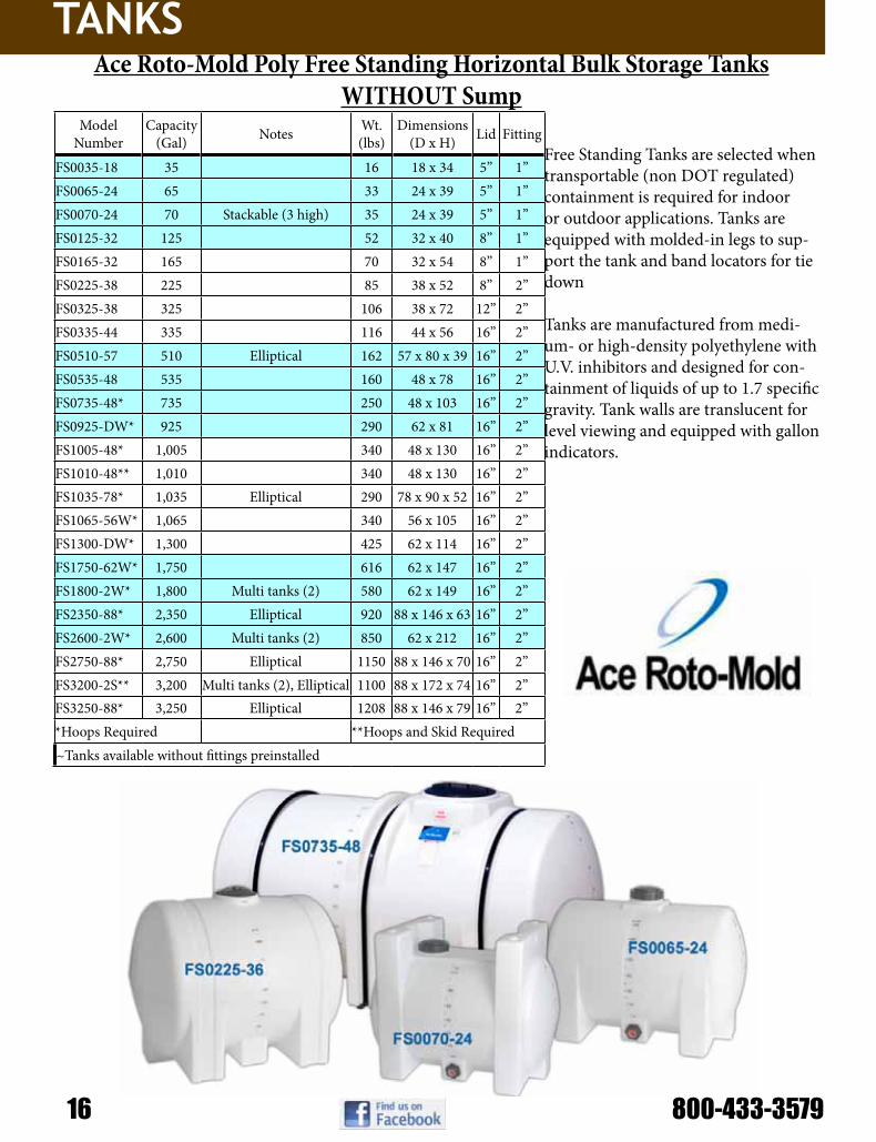
Free Standing Tanks are selected when transportable (non DOT regulated) containment is required for indoor or outdoor applications. Tanks are equipped with molded-in legs to sup-port the tank and band locators for tie down
Tanks are manufactured from medi-um- or high-density polyethylene with U.V. inhibitors and designed for con-tainment of liquids of up to 1.7 specific gravity. Tank walls are translucent for level viewing and equipped with gallon indicators.
Ace Roto-Mold Poly Free Standing Horizontal Bulk Storage TanksWITHOUT Sump
Model Number
Capacity (Gal) Notes Wt.
(lbs)Dimensions
(D x H) Lid Fitting
FS0035-18 35 16 18 x 34 5” 1”FS0065-24 65 33 24 x 39 5” 1”FS0070-24 70 Stackable (3 high) 35 24 x 39 5” 1”FS0125-32 125 52 32 x 40 8” 1”FS0165-32 165 70 32 x 54 8” 1”FS0225-38 225 85 38 x 52 8” 2”FS0325-38 325 106 38 x 72 12” 2”FS0335-44 335 116 44 x 56 16” 2”FS0510-57 510 Elliptical 162 57 x 80 x 39 16” 2”FS0535-48 535 160 48 x 78 16” 2”FS0735-48* 735 250 48 x 103 16” 2”FS0925-DW* 925 290 62 x 81 16” 2”FS1005-48* 1,005 340 48 x 130 16” 2”FS1010-48** 1,010 340 48 x 130 16” 2”FS1035-78* 1,035 Elliptical 290 78 x 90 x 52 16” 2”FS1065-56W* 1,065 340 56 x 105 16” 2”FS1300-DW* 1,300 425 62 x 114 16” 2”FS1750-62W* 1,750 616 62 x 147 16” 2”FS1800-2W* 1,800 Multi tanks (2) 580 62 x 149 16” 2”FS2350-88* 2,350 Elliptical 920 88 x 146 x 63 16” 2”FS2600-2W* 2,600 Multi tanks (2) 850 62 x 212 16” 2”FS2750-88* 2,750 Elliptical 1150 88 x 146 x 70 16” 2”FS3200-2S** 3,200 Multi tanks (2), Elliptical 1100 88 x 172 x 74 16” 2”FS3250-88* 3,250 Elliptical 1208 88 x 146 x 79 16” 2”*Hoops Required **Hoops and Skid Required~Tanks available without fittings preinstalled

TANKS
Ace Roto-Mold Poly Free Standing Horizontal Bulk Storage TanksWITH Sump
Ace Roto-Mold J-Bolt Straps for Free-Standing Horizontal Leg Tanks
Ace Roto-Mold “Foot” Straps for Free-Standing Horizontal Leg Tanks
Model Number
Capacity (Gal) Notes Wt.
(lbs)Dimensions
(D x H) Lid Fitting
FM0015-14S 15 11 14 x 30 5” N/AFM0025-16S 25 15 16 x 34 5” N/AFM0925-DS* 925 Domed Ends 290 62 x 81 16” 2”FM1065-56S* 1,065 340 56 x 105 16” 2”FM1300-DS* 1,300 Domed Ends 425 62 x 114 16” 2”FM1610-78S* 1,610 Center or End Drain, Elliptical 530 78 x 139 x 58 16” 2”FM1750-62S* 1,750 616 62 x 147 16” 2”FM1800-2S* 1,800 Multi tanks (2) 580 62 x 149 16” 2”FM2350-88S* 2,350 Center or End Drain, Elliptical 920 88 x 146 x 63 16” 2”FM2600-2S* 2,600 Multi tanks (2) 850 62 x 212 16” 2”FM2750-88S* 2,750 Center or End Drain, Elliptical 1150 88 x 146 x 70 16” 2”FM3250-88S* 3,250 Center or End Drain, Elliptical 1208 88 x 146 x 79 16” 2”
*Hoops Required
Model Number For Capacity (Gal) Type Notes Dimensions
(W x L)FS0035-SB 35 Stainless Steel Bands 18 Gauge, 10 lbs 2 x 45FS0065-SB 65 Stainless Steel Bands 18 Gauge, 14 lbs 2 x 61FS125/165-SBPJ 125 / 165 Powder Coat Bands 14 Gauge, 16 lbs 3 x 80FS225/325-SBPJ 225 / 335 Powder Coat Bands 14 Gauge, 19 lbs 3 x 95FS0335-SBPJ 335 Powder Coat Bands 14 Gauge, 34 lbs 3 x 110FS0535-SBPJ 535 Powder Coat Bands 14 Gauge, 36 lbs 3 x 120
Model Number For Capacity (Gal) Type Notes Dimensions
(W x L)FS0035-SBPF 35 Powder Coat Bands 14 Gauge, 8 lbs 2 x 47.5FS0065-SBPF 65 Powder Coat Bands 14 Gauge, 12 lbs 2 x 67FS125/165-SBPF 125 / 165 Powder Coat Bands 14 Gauge, 16 lbs 2.5 x 84.5FS225/325-SBPF 225 / 335 Powder Coat Bands 14 Gauge, 19 lbs 2.5 x 99.5FS0335-SBPF 335 Powder Coat Bands 14 Gauge, 34 lbs 2.75 x 116.5FS0535-SBPF 535 Powder Coat Bands 14 Gauge, 36 lbs 2.75 x 125

TANKS
18 800-433-3579
Ace Roto-Mold Hoops, Baffles, Skids for F-S Horizontal Leg Tanks Model Number For Capacity
(Gal) Type Notes Dimensions (D x H)
FS048-HP 735 Hoops Set of 3 1.315 ODFS062-HP-925 925 Hoops Set of 2 1.66 ODFS062-HP-1300 1,300 Hoops Set of 3 1.66 ODFS062-HP-1750 1,750 Hoops Set of 4 1.66 ODFS062-HP-1800C 1,800 Hoops Set of 4 1.66 ODFS062-HP-2600C 2,600 Hoops Set of 6 1.66 ODFS0510-HP 510 Hoops Set of 3 1.315 ODFS1005-HP 1,005 Hoops Set of 4 1.315 ODFS1010-HP 1,010 Hoops Set of 4 1.315 ODFS1035-HP 1,035 Hoops Set of 3 1.66 ODFS1065-HP 1,065 Hoops 3 1.315 ODFS1065-BAF 1,065 Baffles 38 lbs N/AFS1610-HP 1,610 Hoops Set of 4 1.66 ODFS2350-HP 2,350 Hoops Set of 4 1.90 ODFS2750-HP 2,750 Hoops Set of 4 1.90 ODFS3200-HP 3,200 Hoops Set of 4 1.66 ODFS3250-HP 3,250 Hoops Set of 4 1.90 ODFS3250-LAD 3,250 Ladder 46 lbs 16 x 78FS0925-SK 925 Skid 280 lbs 61 x 64FS1010-SK 1,010 Skid 409 lbs 53 x 115FM-1065-SKS 1,065 Skid w/ Sump 280 lbs 61 x 78FS1065-SKW 1,065 Skid w/o Sump 200 lbs 59 x 100FS1300-SK 1,300 Skid 450 lbs 64 x 104FM1610-SKC 1,610 Skid w/ Center Sump 490 lbs 83 x 107FM1610-SKE 1,610 Skid w/ End Sump 490 lbs 83 x 112FS1750-SK 1,750 Skid 604 lbs 64 x 138FM1800-SKS 1,800 Skid w/ Sump 580 lbs 64 x 125FS1800-SKW 1,800 Skid w/o Sump 382 lbs 64 x 125FM2350/3250-SKC 2350/2750/3250 Skid w/ Center Sump 1060 lbs 88 x 141FM2350/3250-SKE 2350/2750/3250 Skid w/ End Sump 1060 lbs 88 x 141FS2350/3250-SK 2350/2750/3250 Skid 1078 lbs 88 x 141FS2600-SK 2,600 Skid 900 lbs 64 x 201FS3200-SK 3,200 Skid 1163 lbs 90 x 168

TANKS
Model Number Capacity (Gal)
Wt. (lbs)
Dimensions (W x L x H) Lid Fitting
HE0085-36 85 42 36 x 47 x 21 7” No FittingHE0200-41 200 82 41 x 66 x 26 8” ¾” & 1-1/4”HE0300-48 300 112 48 x 70 x 30 8” ¾” & 1-1/4”HE0400-57 400 127 57 x 70 x 36 8” ¾” & 1-1/4”HE05000-57 500 163 57 x 82 x 36 8” ¾” & 1-1/4”HED0500-57 500 Deep Sump 163 57 x 82 x 36 8” ¾” & 1-1/4”HE0750-69 750 220 69 x 89 x 42 16” 1-1/4” & 2”HED0750-69 750 Deep Sump 220 69 x 89 x 42 16” 1-1/4” & 2”HE0850-69 850 246 69 x 89 x 46 16” 1-1/4” & 2”HED0850-69 850 Deep Sump 246 69 x 89 x 46 16” 1-1/4” & 2”HE1000-78* 1,000 285 78 x 90 x 49 16” 1-1/4” & 2”HED1000-78* 1000 Deep Sump 285 78 x 90 x 49 16” 1-1/4” & 2”HE1250-78† 1,250 400 78 x 92 x 60 16” 1-1/4” & 2”HED1250-78† 1250 Deep Sump 400 78 x 92 x 60 16” 1-1/4” & 2”HE1600-78† 1,600 439 78 x 138 x 49 16” 2”HED1600-78† 1600 Deep Sump 439 78 x 138 x 49 16” 2”*Optional baffles available †Baffles included standard
Ace Roto-Mold Elliptical Tanks
Model Number For Capacity (Gal)
Est Weight in lbs
Bands (W x L)
HE00085-C 85 40 2” x 55”HE0200-C 200 140 3 x 61HE0300-C 300 155 3 x 74HE0400-C 400 190 4 x 88HE0500-C 500 202 4 x 88HE0750-C 750 405 4 x 91HE0850-C 850 408 4 x 99HE1000-C 1,000 515 4 x 10⁵HE1250-C 1,250 520 4 x 126HE1600-C 1,600 578 3.5 x 124
Ace Roto-Mold Elliptical Tank Cradles

TANKS
20 800-433-3579
Model Number Capacity (Gal)
Wt. (lbs)
Dimensions (D x H) Lid Fitting
HZ0025-23 25 14 23 x 22 5” ¾”HZ0055-23 55 23 23 x 38 5” ¾”HZ0075-24 75 31 24 x 47 5” ¾”HZ0095-24 95 35 24 x 56 5” 1¼”HZ0100-23 100 40 23 x 64 5” 1¼”HZ0110-30 110 40 30 x 44 8” 1¼”HZ0150-30 150 x 30 48 30 x 57 8” ¾” & 1¼”HZ0150-32 150 x 32 48 32 x 52 8” ¾” & 1¼”HZ0200-32 200 x 32 64 32 x 68 8” ¾” & 1¼”HZ0200-38 200 x 38 64 38 x 51 8” ¾” & 1¼”HZ0300-38 300 88 38 x 76 8” ¾” & 1¼”HZ0500-48 500 122 48 x 79 8” ¾” & 1¼”
Ace Roto-Mold Round Horizontal Tanks
Model Number For Capacity (Gal)
Est. Weight in lbs
Bands (W x L)
HZ0025-C 25 20 1.5 x 50 (Stainless)HZ0055-C 55 24 2 x 50.5 (Stainless)HZ0075-C 75 36 2 x 51.5HZ0095-C 95 38 2 x 51.5HZ0100-C 100 40 1.75 x 39.5HZ0110-C 110 40 2.75 x 60HZ0153-C 150 x 30 57 2.75 x 55HZ0150-C 150 x 32 56 2.75 x 56HZ0232-C 200 x 32 110 2.75 x 57HZ0238-C 200 x 38 85 2.75 x 65HZ0300-C 300 145 2.75 x 69.5HZ0500-C 500 170 2.75 x 86.5
Ace Roto-Mold Round Horizontal Tank Cradles

TANKS
Part No. Capacity Weight Dimensions Overall Height Lid Fitting Specific Gravity
CB0055-23 55 Gallon – 15 deg 26 23 x 39 52” 8” 1 1/2” 2CB0100-23 100 Gallon – 15 deg 36 23 x 65 78” 8” 1 1/2” 2CB0145-36 145 Gallon – 15 deg 52 36 x 43 56” 8” 2” 2CB0150-36 150 Gallon – 45 deg 63 36 x 51 63” 12” 2” 2CB0200-36 200 Gallon – 15 deg 58 36 x 55 68” 8” 2” 2CB0200-42 200 Gallon – 45 deg 77 42 x 55 67” 12” 2” 2
CBFD240-42240 Gal Full Drain – 45
deg 77 42 x 59 69” 12” 2” 1.7
CB0250-36 250 Gallon – 15 deg 76 36 x 67 80” 8” 2” 2CB0325-36 325 Gallon – 15 deg 92 36 x 84 97” 8” 2” 2CB0345-52 345 Gallon – 45 deg 102 52 x 58 70” 12” 2” 2CB0350-42 350 Gallon – 45 deg 120 42 x 81 93” 12” 2” 2CB0500-52 500 Gallon – 45 deg 132 52 x 81 92” 12” 2” 2CB0850-90 850 Gallon – 15 deg 212 90 x 56 67” 16” 2” 1.7CB1150-90 1150 Gallon – 15 deg 242 90 x 67 78” 16” 2” 1.7CB1550-90 1550 Gallon – 30 deg 286 90 x 88 97” 16” 2” 1.7CB2450-90 2450 Gallon – 15 deg 437 90 x 114 125” 16” 2” 1.7CB2550-90 2550 Gallon – 30 deg 502 90 x 126 134” 16” 2” 1.7
Ace Roto-Mold Cone Bottom Flat Top Tanks
Ace Roto-Mold Cone Bottom Dome Top Tanks Part No. Capacity Weight Dimensions Overall
Height Lid Fitting Specific Gravity
CB0300-42 300 Gallon – 45 deg 102 42 x 67 79” 16” 2” 2
CB0800-86 800 Gallon – 15 deg 182 86 x 48 58” 16” 2” 1.7
CB1000-64 1000 Gallon – 45 deg 252 64 x 98 112” 16” 2” 1.7
CB1000-90 1000 Gallon – 15 deg 212 90 x 54 64” 16” 2” 1.7
CB1200-90 1200 Gallon – 15 deg 242 90 x 62 74” 16” 2” 1.7
CB1300-90 1300 Gallon – 15 deg 262 90 x 65 75” 16” 2” 1.7
CB1490-64 1490 Gallon – 45 deg 342 64 x 132 146” 16” 2” 1.7
CB1600-90 1600 Gallon – 30 deg 286 90 x 85 94” 16” 2” 1.7
CB1700-86 1700 Gallon – 15 deg 286 86 x 85 96” 16” 2” 1.7
CB2495-90 2495 Gallon – 30 deg 487 90 x 119 129” 16” 2” 1.7
CB2500-90 2500 Gallon – 15 deg 437 90 x 111 122” 16” 2” 1.7
CB2600-90 2600 Gallon – 30 deg 502 90 x 123 132” 16” 2” 1.7
CB2600-86 2600 Gallon – 45 deg 502 86 x 146 158” 16” 2” 1.7
CB3000-90 3000 Gallon – 15 deg 552 90 x 128 138” 16” 2” 1.7
CB3000-96 3000 Gallon – 30 deg 552 96 x 125 137” 16” 2” 1.7
CB4600-102* 4600 Gallon – 15 deg 1202 102 x 155 166” 16” 2” 1.7
CB4900-102* 4900 Gallon – 15 deg 1302 102 x 159 170” 16” 2” 1.7
CB6900-122* 6900 Gallon – 15 deg 1702 122 x 168 178” 16” 3” 1.7
CB8250-122* 8250 Gallon – 15 deg 2102 122 x 195 206” 16” 3” 1.7
*Heavy Duty Fitting

TANKS
22 800-433-3579
Part No. Capacity Weight Dimensions Lid FittingIN0015-19 15 Gallon 12 19 x 24 12” 2” FPTINFD15-19 15 Gallon Full Drain 12 19 x 27 12” 1 1/2” FPT BOSSIN0015-19SM 15 Gallon Side Mount 10 19 x 24 12” 2” FPTIN0030-24 30 Gallon 17 24 x 30 12” 2” FPTINFD30-24 30 Gallon Full Drain 17 24 x 33 12” 1 1/2” FPT BOSSIN0040-30 40 Gallon Full Drain 26 30 x 34 12” 2” MPT BOSSIN0055-24 55 Gallon x 24 24 24 x 42 12” 2” FPTINFD55-24 55 Gallon x 24 Full Drain 24 24 x 46 12” 1 1/2” FPT BOSSINFD60-30 60 Gallon x 30 Full Drain 28 30 x 38 16” 2” MPT BOSSIN0085-30 85 Gallon 37 30 x 43 12” 2” FPTINFD85-30 85 Gallon Full Drain 37 30 x 48 12” 2” FPT BOSSIN0110-30 110 Gallon 44 30 x 51 12” 2” FPTINFD110-30 110 Gallon Full Drain 44 30 x 56 12” 2” FPT BOSS
Ace Roto-Mold Inductor Tanks
Ace Roto-Mold Inductor Tank StandsPart No. Capacity Weight
IN15-ST 15 gal. 15INFD15-ST 15 gal – 4” taller for Full-Drain tank 16IN30/55-ST 30 or 55 gal. (for 24” dia. tanks) 18INFD30/55-ST 30 or 55 gal – 4” taller for Full-Drain tank 19IN40/85-ST 40, 60, 85 or 110 gal. (for 30” dia. tanks) 40IN40-ST 40 gal. (designed for UPS shipments) 40
Ace Roto-Mold Pick-Up Tanks
Part No. Capacity Weight Dimensions Lid FittingPU0200-52 200 Gallon 56 52 x 30 8” 2”PU0205-52 205 Gallon 87 52 x 52 x 26 7” 2”PU0305-60* 305 Gallon 107 60 x 58 x 30 7” 2”PU0350-62 350 Gallon 94 62 x 34 8” 2”PU0450-62 450 Gallon 104 62 x 41 8” 2”
Part No. Capacity Description Weight Dimensions LidSM0014-14S 14 Gallon Roto w/sump 8 14 x 30 x 14 5”SS0014-14 14 Gallon Roto w/out sump 8 14 x 30 x 14 5”SM0025-18S 25 Gallon Roto w/sump 14 18 x 34 x 18 5”SS0025-18 25 Gallon Roto w/out sump 14 18 x 34 x 18 5”SB00015 15 Gallon Blow molded 7.5 34 x 16 x 13 5”SB00025 25 Gallon Blow molded 12 36 x 18 x 17 5”SB00040 40 Gallon Blow molded 17.5 24 x 36 x 19 5”SB00060 60 Gallon Blow molded 21 24 x 36 x 26 5”12499 5” Lid w/Short Lanyard
Ace Roto-Mold Spot Sprayer & Applicator Tanks

TANKS
Part No. Capacity Weight Dimensions LidST0035-32† 35 Gallons 30 32 x 32 x 15 7”ST0070-32† 70 Gallons 42 32 x 32 x 25 7”ST0120-32 120 Gallons 77 32 x 32 x 38 7”ST0180-42 180 Gallons 126 42 x 42 x 35 7”ST0240-42 240 Gallons 164 42 x 42 x 45 7”
Ace Roto-Mold Stackable Totes
Part No. Capacity Weight Dimensions Lid FittingSP0150-PPTK* 150 Gal Rectangle 82 24 x 40 x 42 7” 2”SP0300-PPTK* 300 Gal Rectangle 122 48 x 40 x 42 7” 2”VT0110-32 110 Gal Tank Only w/sump 42 32 x 41 5” 2” TopVT0210-40 210 Gal Tank Only 58 40 x 49 5” 2” Top
Ace Roto-Mold Pallet Tank Only
Part No. Description Weight DimensionsST70/120-SK 35, 70 or 120 Gallon Steel Skid 50 30 x 30 x 8ST024-LG 35, 70 or 120 Gallon 24” Leg Kit 24 5 x 5 x 26ST036-LG 35, 70 or 120 Gallon 36” Leg Kit 70 8 x 8 x 41ST70/120-DT 35, 70 or 120 Gallon Drip Tray Kit 15 5 x 20 x 35ST70/120-PL Stackable Tote Plumbing Kit19508 180 & 240 Gallon Tote Adaptor 55 42 x 42 x 10ST180/240-ST 180 & 240 Gallon Steel Stand 175 44 x 44 x 27ST180/240-DT 180 & 240 Gallon Drip Tray Kit 17 5 x 20 x 46
Ace Roto-Mold Stackable Tote Accessories
Part No. Capacity Weight Dimensions Lid FittingSP0150-PP 150 Gal Pallet & Tank 203 26 x 43 x 47 7” 2”SP0150-2TPP 150 Gal Pallet Pak-2 Tanks, Pallet, Frame 270 50 x 43 x 47 7” 2”SP0300-PP 300 Gal Pallet Pak-1 Tank, Pallet, Frame 316 50 x 43 x 47 7” 2”VT0110-PP 110 Gal Pallet & Tank 70 33 x 40 x 44 5” 2” TopVT0210-PP 210 Gal Pallet & Tank 84 41 x 52 5” 2” Top
Ace Roto-Mold Pallet Packs

TANKS
24 800-433-3579
Part No. Capacity Weight Dimensions Lid FittingSP0008-VM† 8 Gal Loaf 7 12 x 16 x 17 5” 1/2” FPT BOSSSP0012-RT† 12 Gal Rectangle 10 14 x 18 x 12 5” 3/4”SP0012-VM† 12 Gal Loaf 10 12 x 16 x 22 5” 1/2” FPT BOSSSP0019-VM† 19 Gal Loaf 15 12 x 16 x 28 5” 1/2” FPT BOSSSP0020-LC† 20 Gal Rectangle 12 14 x 28 x 12 5” 3/4”
Ace Roto-Mold Applicator Tanks with Sump
Part No. Capacity Weight Dimensions Lid FittingSP002.8-RT 2.8 Gal 4 9 x 14 x 9 5” **SP0005-RT 5 Gal 6 10 x 22 x 8 5” **
SP0006-2P 6 Gal w/ pump mount & 2” lid 6 12 x 15 x 8 2” **
SP0006-5N 6 Gal w/ 5” lid 6 12 x 15 x 8 5” **SP0007-RT 7 Gal 8 9 x 14 x 15 5” **SP0016-MM 16 Gal 10 14 x 21 x 14 5” **SP0020-OM 20 Gal Upright 17 11 x 15 x 31 5” 1/2” outlet
Ace Roto-Mold Rectangle, Flat Bottom Tanks
Part No. Capacity Weight Dimensions Lid FittingSPBM2.5-RT 2.5 Gal Rectangle 3 7 x 15 x 14 5” 3/4”SP0003-RT† 3 Gal Rectangle 4 7 x 12 x 14 5” 3/4”SP003.5-CL† 3.5 Gal Cylinder 5 11 x 15 5” 3/4”SP0004-SQ5† 4 Gal Square 6 11 x 11 x 15 5” 1-1/4”SP0004-SQ8† 4 Gal Square 7 11 x 11 x 14 8” 1-1/4”SP0005-SQ5† 5 Gal Square 6 11 x 11 x 20 5” 1-1/4”SP0005-SQ8† 5 Gal Square 7 11 x 11 x 18 8” 1-1/4”SP0010-SQ8† 10 Gal Square 10 13 x 13 x 21 8” 1-1/4”
Ace Roto-Mold Rinse Tanks
Part No. Capacity Weight Dimensions Lid FittingSP0008-VM† 8 Gal Loaf 7 12 x 16 x 17 5” 1/2” FPT BOSSSP0012-RT† 12 Gal Rectangle 10 14 x 18 x 12 5” 3/4”SP0012-VM† 12 Gal Loaf 10 12 x 16 x 22 5” 1/2” FPT BOSSSP0019-VM† 19 Gal Loaf 15 12 x 16 x 28 5” 1/2” FPT BOSSSP0020-LC† 20 Gal Rectangle 12 14 x 28 x 12 5” 3/4”
Ace Roto-Mold Rectangle, Flat Bottom Tanks
TANKS
Part No. Capacity Weight Dimensions Lid Fitting
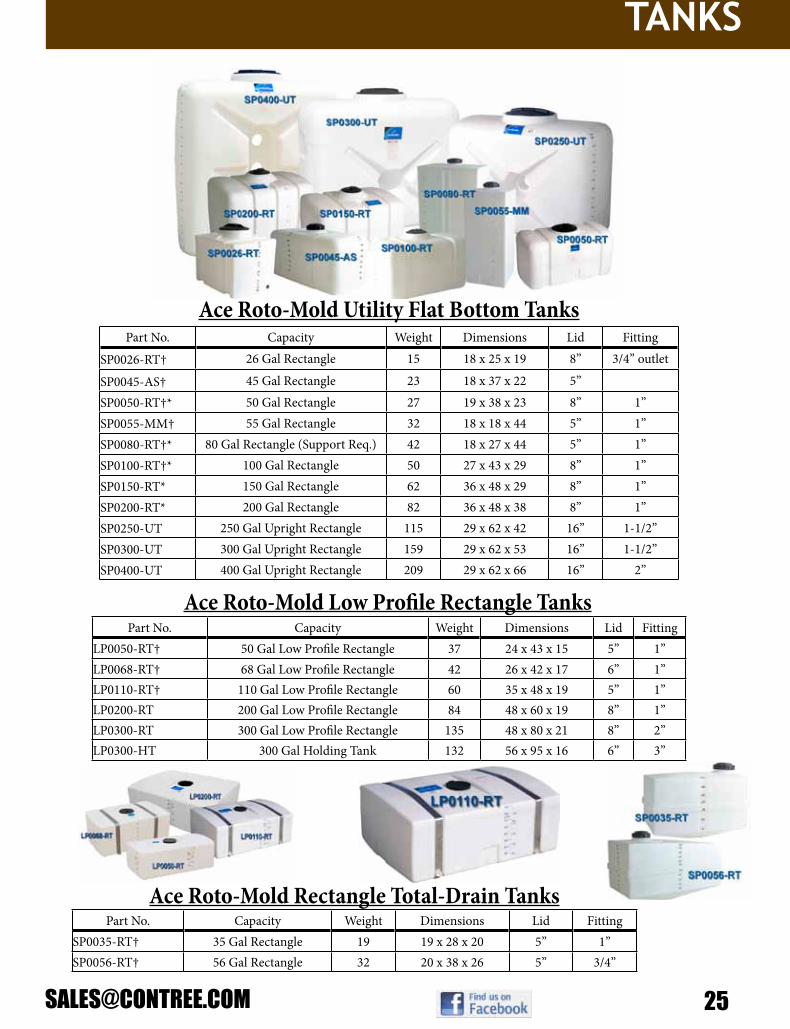
SP0026-RT† 26 Gal Rectangle 15 18 x 25 x 19 8” 3/4” outlet
SP0045-AS† 45 Gal Rectangle 23 18 x 37 x 22 5”
SP0050-RT†* 50 Gal Rectangle 27 19 x 38 x 23 8” 1”SP0055-MM† 55 Gal Rectangle 32 18 x 18 x 44 5” 1”SP0080-RT†* 80 Gal Rectangle (Support Req.) 42 18 x 27 x 44 5” 1”SP0100-RT†* 100 Gal Rectangle 50 27 x 43 x 29 8” 1”SP0150-RT* 150 Gal Rectangle 62 36 x 48 x 29 8” 1”SP0200-RT* 200 Gal Rectangle 82 36 x 48 x 38 8” 1”SP0250-UT 250 Gal Upright Rectangle 115 29 x 62 x 42 16” 1-1/2”SP0300-UT 300 Gal Upright Rectangle 159 29 x 62 x 53 16” 1-1/2”SP0400-UT 400 Gal Upright Rectangle 209 29 x 62 x 66 16” 2”
Part No. Capacity Weight Dimensions Lid FittingLP0050-RT† 50 Gal Low Profile Rectangle 37 24 x 43 x 15 5” 1”LP0068-RT† 68 Gal Low Profile Rectangle 42 26 x 42 x 17 6” 1”LP0110-RT† 110 Gal Low Profile Rectangle 60 35 x 48 x 19 5” 1”LP0200-RT 200 Gal Low Profile Rectangle 84 48 x 60 x 19 8” 1”LP0300-RT 300 Gal Low Profile Rectangle 135 48 x 80 x 21 8” 2”LP0300-HT 300 Gal Holding Tank 132 56 x 95 x 16 6” 3”
Part No. Capacity Weight Dimensions Lid FittingSP0035-RT† 35 Gal Rectangle 19 19 x 28 x 20 5” 1”SP0056-RT† 56 Gal Rectangle 32 20 x 38 x 26 5” 3/4”
Ace Roto-Mold Utility Flat Bottom Tanks
Ace Roto-Mold Low Profile Rectangle Tanks
Ace Roto-Mold Rectangle Total-Drain Tanks

TANKS
26 800-433-3579
Part No. Capacity Weight DimensionsPC0035-SB†* 35 Gallon Set 3 2 x 50.5PC0050-SBP 50 Gallon Set 6 2.5” x 57.5”PC0100-SBP† 100 Gallon Set 20 2.5 x 76PC0150-SBP† 150 Gallon Set 30 3.5 x 82PC0200-SBP† 200 Gallon Set 36 3.5 x 98PC0300-SBP† 300 Gallon Set 40 4 x 100
Ace Roto-Mold PCO Tank Bands
Part No. Capacity Weight Dimensions
SP0050-SBP 50 Gallon Rectangle Kit 7 2 x 54.5
LP0050-SBP 50 Gallon Low Profile Rectangle Kit 7 2 x 51LP0068-SBP 68 Gallon Low Profile Rectangle Kit 7 2 x 58SP0080-SBP 80 Gallon Rectangle Support Band 21 3 x 93SP0100-SBP 100 Gallon Rectangle Kit 11 2.25 x 70.5LP0110-SBP 110 Gallon Low Profile Rectangle Kit 11 2 x 69SP0150-SBP 150 Gallon Rectangle Kit 14 2.25 x 77.5SP0200-SBP 200 Gallon Rectangle Kit 16 2.25 x 94LP0200-SBP 200 Gallon Low Profile Rectangle Kit 14 2 x 82.5LP0300-SBP 300 Gallon Low Profile Rectangle Kit 16 2 x 86.5
Ace Roto-Mold Utility & Low Profile Tank Bands
Part No. Capacity Weight Dimensions Lid FittingPCO035-16W† 35 Gallon 26 16 x 35 x 21 5” 1”PCO050-19S† 50 Gallon w/ sump 27 19 x 38 x 23 8” 1”PCO050-19W† 50 Gallon 27 19 x 38 x 23 8” 1”PCO100-30S† 100 Gallon w/ sump 52 30 x 38 x 29 8” 1”PCO100-30W† 100 Gallon 52 30 x 38 x 29 8” 1”PCO150-37S 150 Gallon w/ sump 63 37 x 48 x 29 12” 1 1/4”PCO150-37W 150 Gallon 63 37 x 48 x 29 12” 1 1/4”PCO200-37S 200 Gallon w/ sump 84 37 x 48 x 38 12” 1 1/4”PCO200-37W 200 Gallon 84 37 x 48 x 38 12” 1 1/4”PCO300-37S 300 Gallon w/ sump 160 37 x 69 x 40 16” 2”PCO300-37W 300 Gallon 160 37 x 69 x 40 16” 2”
Ace Roto-Mold Pest Control Operator Tanks

TANKS
Part No. Capacity Weight Dimensions Lid FittingOT0300-31 300 Gal Oval 102 31 x 49 x 56 16” 3/4” and 1-1/4”TD0250-36 250 Gal Tear Drop 97 36 x 52 x 45 12” 3/4” and 1-1/4”TD0300-36 300 Gal Tear Drop 109 36 x 62 x 45 12 3/4” and 1-1/4”CAW0200-24 200 Gallon 82 24 x 55 x 46 8” 3/4” & 1-1/4”CAW0250-24 250 Gallon 97 24 x 61 x 51 8” 3/4” & 1-1/4”
Ace Roto-Mold Tractor Mounted Tanks
Part No. Capacity Weight Dimensions Lid FittingGV1050-86 1050 Gallon 177 86 x 50 16” 2”GV1350-86 1350 Gallon 209 86 x 62 16” 2”GV1500-86 1500 Gallon 230 86 x 69 16” 2”GV1650-86 1650 Gallon 257 86 x 74 16” 2”
Ace Roto-Mold Gusseted Top Vertical Tanks
Part No. Capacity Weight Dimensions Lid Fitting Specific Gravity
WO2500-VT 2500 Gallon 392 96 x 92 16” 2” 1WO3000-VT 3000 Gallon 487 96 x 109 16” 2” 1
Ace Roto-Mold H2O Only Vertical Tanks
Part No. Capacity Weight BandsTD0250-C 250 Gal 96 2.5” x 74.5”TD0300-C 300 Gal 108 2.5” x 74.5”CAW0200-C 200 Gallon 135 3 x 60 - 3 x 40CAW0250-C 250 Gallon 143 3 x 72 - 3 x 51
Ace Roto-Mold Tractor Mounted Tank Cradles

TANKS
28 800-433-3579
Part No. Capacity Weight Dimensions Lid FittingCM0500-48 500 Gal w/ sump 202 48 x 90 x 38 16” 2”CM0750-48 750 Gal w/ sump 262 48 x 90 x 50 16” 2”CC1000-58S 1000 Gal w/ sloped sump 345 58 x 115 x 47 16” 2”CC1000-58N 1000 Gal narrow bottom w/ sloped sump 345 58 x 115 x 51 16” 2”CM1000-58B 1000 Gal w/ box sump 350 58 x 115 x 47 16” 2”CC1250-58S 1250 Gal w/ sloped sump 480 58 x 115 x 57 16” 2”CC1250-58N 1250 Gal narrow bottom w/ sloped sump 480 58 x 115 x 61 16” 2”CM1250-58B 1250 Gal w/ box sump 485 58 x 115 x 57 16” 2”CC1500-58S 1500 Gal w/ sloped sump 550 58 x 115 x 66 16” 2”CC1500-58N 1500 Gal narrow bottom w/ sloped sump 550 58 x 115 x 70 16” 2”CM1500-58B 1500 Gal w/ box sump 550 58 x 115 x 66 16” 2”
Part No. Capacity Kit
CC0500-HPS 500 Gallon Hoop 1 Hoop (1)-1 2/3” pipe
CC0750-HPS 750 Gallon Hoop 1 Hoop (1)-1 2/3” pipeCC1000-HP 1000 Gallon Hoops 1 Set (3)-2 3/8” pipesCC1250-HP 1250 Gallon Hoops 1 Set (3)-2 3/8” pipesCC1500-HP 1500 Gallon Hoops 1 Set (5)-2 3/8” pipes
Ace Roto-Mold Crop Care Tank Hoops
Ace Roto-Mold Crop Care Tanks

TANKS
Part No. Description Weight DimensionsAST19365 7” Access Extension – Black 13 32.5 x 13.5AST19379 7” Access Extension – White 13 32.5 x 13.5AST19212 16” Access Extension – Black 35 32.5 x 16AST19214 16” Access Extension – White 35 32.5 x 22AST19368 16” Access Extension – Green 35 32.5 x 16AST19211 24” Access Cover – Black 17 32.5 x 8AST19213 24” Ace Access Cover – White 14 32.5 x 8AST19366 24” Access Cover – Green 17 32.5 x 8AST19257 8” Riser and Lid – Black 20 32.5 x 29AST19258 8” Riser and Lid – White 20 32.5 x 29AST10078 4” Sanitary Gasket 1 4.00 ID x 8 ODAST10084 4” Sch. 40 Gasket 1 4.25 ID x 8 ODAST19256 4” Gasket Retainer w/ Hardware 1
AST10154 Divider Panel Assembly for 1000 gal w/ Hardware 52
AST19233 Divider Panel Assembly for 1250/1500 gal w/ Hardware 46
AST18000-xx Internal Plumbing Kit
Ace Roto-Mold Septic & Cistern Tank Accessories
Part No. Capacity Weight DimensionsAST-0300-1 300 Gallon Pump Tank 137 54 x 56AST-0500-1 500 Gallon Pump Tank 197 63 x 74AST-0750-1 750 Gallon- 1 Compartment 259 60 x 70 x 60AST-1000-1 1000 Gallon- 1 Compartment 396 60 x 101 x 60AST-1000-2 1000 Gallon- 2 Compartment 448 60 x 101 x 60AST-1250-1 1250 Gallon- 1 Compartment 443 58 x 118 x 72AST-1250-2 1250 Gallon- 2 Compartment 492 58 x 118 x 72AST-1500-1 1500 Gallon- 1 Compartment 534 58 x 137 x 72AST-1500-2 1500 Gallon- 2 Compartment 580 58 x 137 x 72
Ace Roto-Mold Septic Tank
Part No. Capacity Weight DimensionsAST-0325-1W 325 Gallon Cistern 134 54 x 56AST-0525-1W 525 Gallon Cistern 194 63 x 74AST-0850-1W 850 Gallon Cistern Single Compartment 259 60 x 70 x 60AST-1150-1W 1150 Gallon Cistern Single Compartment 414 60 x 101 x 60AST-1450-1W 1450 Gallon Cistern Single Compartment 473 58 x 118 x 72AST-1700-1W 1700 Gallon Cistern Single Compartment 567 58 x 137 x 72
Ace Roto-Mold Cistern Tank

TANKS
30 800-433-3579
Part No. Description Weight DimensionsACT1000-LPB 1000 Gallon Low Profile Cistern w/Burial Lid 559 98 x 111 x 36ACT1000-LPG 1000 Gallon Low Profile Cistern w/Ground Access Assembly 595 98 x 111 x 36ACT1500-LPB 1500 Gallon Low Profile Cistern w/Burial Lid 702 98 x 111 x 48ACT1500-LPG 1500 Gallon Low Profile Cistern w/Ground Access Assembly 738 98 x 111 x 48ACT2000-LPB 2000 Gallon Low Profile Cistern w/Burial Lid 917 98 x 158 x 45ACT2000-LPG 2000 Gallon Low Profile Cistern w/Ground Access Assembly 953 98 x 158 x 45ACT2500-LPB 2500 Gallon Low Profile Cistern w/Burial Lid 1031 98 x 158 x 54ACT2500-LPG 2500 Gallon Low Profile Cistern w/Ground Access Assembly 1067 98 x 158 x 54ACT-16053† Aquifer 24” Burial lid & Gasket 17 35 x 8ACT-16052 28” Aquifer Ground Access Assembly 53 34 x 38ACT-16054† 16” Aquifer Ground Access Assembly 43 34 x 24
Ace Roto-Mold AQUIFER Low Profile Cistern Tanks
TANKS
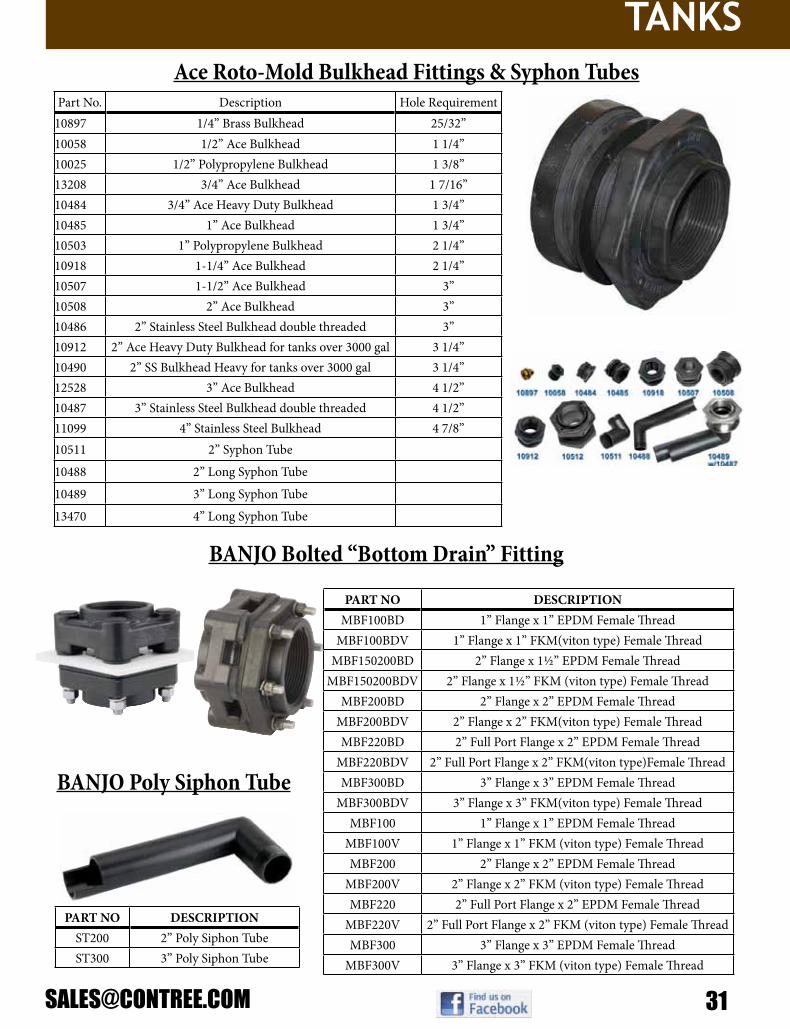
Part No. Description Hole Requirement10897 1/4” Brass Bulkhead 25/32”10058 1/2” Ace Bulkhead 1 1/4”10025 1/2” Polypropylene Bulkhead 1 3/8”13208 3/4” Ace Bulkhead 1 7/16”10484 3/4” Ace Heavy Duty Bulkhead 1 3/4”10485 1” Ace Bulkhead 1 3/4”10503 1” Polypropylene Bulkhead 2 1/4”10918 1-1/4” Ace Bulkhead 2 1/4”10507 1-1/2” Ace Bulkhead 3”10508 2” Ace Bulkhead 3”10486 2” Stainless Steel Bulkhead double threaded 3”10912 2” Ace Heavy Duty Bulkhead for tanks over 3000 gal 3 1/4”10490 2” SS Bulkhead Heavy for tanks over 3000 gal 3 1/4”12528 3” Ace Bulkhead 4 1/2”10487 3” Stainless Steel Bulkhead double threaded 4 1/2”11099 4” Stainless Steel Bulkhead 4 7/8”10511 2” Syphon Tube
10488 2” Long Syphon Tube
10489 3” Long Syphon Tube
13470 4” Long Syphon Tube
Ace Roto-Mold Bulkhead Fittings & Syphon Tubes
PART NO DESCRIPTIONMBF100BD 1” Flange x 1” EPDM Female Thread
MBF100BDV 1” Flange x 1” FKM(viton type) Female ThreadMBF150200BD 2” Flange x 1½” EPDM Female Thread
MBF150200BDV 2” Flange x 1½” FKM (viton type) Female ThreadMBF200BD 2” Flange x 2” EPDM Female Thread
MBF200BDV 2” Flange x 2” FKM(viton type) Female ThreadMBF220BD 2” Full Port Flange x 2” EPDM Female Thread
MBF220BDV 2” Full Port Flange x 2” FKM(viton type)Female ThreadMBF300BD 3” Flange x 3” EPDM Female Thread
MBF300BDV 3” Flange x 3” FKM(viton type) Female ThreadMBF100 1” Flange x 1” EPDM Female Thread
MBF100V 1” Flange x 1” FKM (viton type) Female ThreadMBF200 2” Flange x 2” EPDM Female Thread
MBF200V 2” Flange x 2” FKM (viton type) Female ThreadMBF220 2” Full Port Flange x 2” EPDM Female Thread
MBF220V 2” Full Port Flange x 2” FKM (viton type) Female ThreadMBF300 3” Flange x 3” EPDM Female Thread
MBF300V 3” Flange x 3” FKM (viton type) Female Thread
BANJO Bolted “Bottom Drain” Fitting
PART NO DESCRIPTIONST200 2” Poly Siphon TubeST300 3” Poly Siphon Tube
BANJO Poly Siphon Tube

TANKS
32 800-433-3579
PART NO DESCRIPTIONPOLY BOLTED TANK FLANGES
BF075 ¾” x 1” Threaded EPDM FlangeBF075V ¾” x 1” Threaded FKM (viton type) FlangeBF100 1” x 1” Threaded EPDM Flange
BF100V 1” x 1” Threaded FKM (viton type) FlangeBF125 1¼” x 1” Threaded EPDM FlangeBF150 1½” x 2” Threaded EPDM Flange
BF150V 1½” x 2” Threaded FKM (viton type) FlangeBF200 2” x 2” Threaded EPDM Flange
BF200V 2” x 2” Threaded FKM (viton type) FlangeBF220 2” x 2” Full Port Threaded EPDM Flange
BF220V 2” x 2” Full Port Threaded FKM (viton type) FlangeBF300 3” x 3” Threaded EPDM Flange
BF300V 3” x 3” Threaded FKM(viton type) Flange
BANJO Poly Bolted Flange Fitting
BANJO Poly Bulkhead FittingsPART NO DESCRIPTION HOLE
SIZE
POLY BULKHEAD FITTINGSTF050 ½” Poly Bulkhead EPDM Tank Fitting 15⁄8”
TF050V ½” Poly Bulkhead FKM(viton type) Tank Fitting 15⁄8”TF075 ¾” Poly Bulkhead EPDM Tank Fitting 15⁄8”
TF075V ¾” Poly Bulkhead FKM(viton type) Tank Fitting 15⁄8”TF100 1” Poly Bulkhead EPDM Tank Fitting 2¼”
TF100V 1” Poly Bulkhead FKM(viton type) Tank Fitting 2¼”TF125 1¼” Poly Bulkhead EPDM Tank Fitting 2¼”
TF125V 1¼” Poly Bulkhead FKM(viton type)Tank Fitting 2¼”TF150 1½” Poly Bulkhead EPDM Tank Fitting 3”
TF150V 1½” Poly Bulkhead FKM(viton type)Tank Fitting 3”TF200 2” Poly Bulkhead EPDM Tank Fitting 3”
TF200V 2” Poly Bulkhead FKM(viton type) Tank Fitting 3”TF200BSP 2” Poly Bulkhead BSP Tank Fitting 3”
TF220 2” Poly Bulkhead EPDM Tank Fitting 3¼”TF220V 2” Poly Bulkhead FKM(viton type) Tank Fitting 3¼”TF300 3” Poly Bulkhead EPDM Tank Fitting 4½”
TF300V 3” Poly Bulkhead FKM(viton type) Tank Fitting 4½”TF300BSP 3” Poly Bulkhead BSP Tank Fitting 4½”
TF400 4” Poly Bulkhead EPDM Tank Fitting 5¾”TF400V 4” Poly Bulkhead FKM(viton type) Tank Fitting 5¾”

TANKS
Part No. Description10631 2” Spin on Kelch Cap13108 3 1/2” Vented Lid & Lanyard Assembly19406 5” Hinged Low-Profile13751 5” Threaded Lid Non-Vented13748 5” Threaded Non-Vented Lid13701 5” Threaded Lid w/ Vent13696 5” Threaded Lid w/ Vent13697 5” Threaded Lid w/ .25” Vent Hole13715 5” Threaded Lid w/ .25” Vent Hole & Lanyard Assembly13709 5” Threaded Lid w/ 2 Way Step Vent13716 5” Threaded Lid w/ Vent & Gasket13714 5” Threaded Lid w/ 2 Way Step Vent & Gasket13717 5” Threaded Lid w/.25 Vent Hold & Gasket12415 7” Spin-on Non-Vented Lid12414 7” Spin-on Spring-Vented Lid12427 7” Spin-on Lid w/ Step Vent10525 8” Threaded Vented Lid & Ring10526 12” Threaded Non-Vented Lid & Ring10527 12” Threaded Vented Lid & Ring10528 16” Threaded Vented Lid & Ring10530 22” Threaded Vented Lid & Ring10520 Breather Only (for 8” & 12” Lids)10529 Breather, 4” Center (for 16” Lids)12460 12” Self-Anchoring Lanyard10873 Short Lanyard – 12”10534 Long Lanyard – 16”19024 Outlet Cap, 3/4”19025 Tether for Outlet Cap10960 Gasket for Outlet Cap
Ace Roto-Mold Tank Lids
PART NO DESCRIPTION BORE SIZE
BORE AREA
VENT AREA
POLY ANTI VORTEX VENT CAPSVC200 2” Anti Vortex Vent Cap w/No Screen 2” 3.1 sq. in 3.9 sq. inVC230 2” Anti Vortex Vent Cap w/12 Mesh 304 SS Screen 2” 3.1 sq. in 3.9 sq. inVC300 3” Anti Vortex Vent Cap w/No Screen 3” 7 sq. in 9 sq. inVC330 3” Anti Vortex Vent Cap w/10 Mesh 304 SS Screen 3” 7 sq. in 9 sq. in
ANTI VORTEX TANK FLANGES
TF100AV 1” Anti Vortex Tank Flanges 2¼”
TF125AV 1¼” Anti Vortex Tank Flanges 2¼”
TF150AV 1½” Anti Vortex Tank Flanges 3”
TF200AV 2” Anti Vortex Tank Flanges 3”
BANJO Anti-Vortex Caps
BANJO brand Tank Lids also available!!! Just ask one of our friendly sales staff for
part number and fitment.

HYPRO
34 800-433-3579
• Self-priming operation; roller pumps should NOT be run dry!• Easily adaptable to PTO or gas engines• Seals are Viton or Buna-N• Super rollers are made from special plastics blend that provide the
chemical resistance of nylon and the life of polypropylene.
•HousingavailableinCastIron(C),Ni-Resist(N)orSilverSeriesXL(XL)®–Ni-Resist is a high nickel content alloy for bettercorrosion resistance–SilverSeriesXL®hasacustomalloythatprovidesthebestcorrosionresistanceandisreadyforusewithchemicalslikeRoundup®
Model Number
Max GPM
Max PSI
Max RPM Description Shipping
Wt Shaft Output
1502C 62.0 200 1000Cast iron 6-roller pump with Super Rollers, Buna-N seals, 1-1/2” NPT ports 30 lbs 15/16” solid
1502N 62.0 200 1000Ni-Resist 6-roller pump with Super Rollers, Buna-N seals, 1-1/2” NPT ports 30 lbs 15/16” solid
1502XL 62.0 200 1000SilverCast 6-roller pump with Super Rollers, Buna-N seals, 1-1/2” NPT ports 30 lbs 15/16” solid
1520-0036PTO shield, pump mounting clip
1700C 45.0 200 1000Cast iron 5-roller pump with Super Rollers, Viton seals, 1” NPT ports 19 lbs 15/16” solid
1700N 45.0 200 1000Ni-Resist 5-roller pump with Super Rollers, Viton seals, 1” NPT ports 19 lbs 15/16” solid
1700XL 45.0 200 1000SilverCast 5-roller pump with Super Rollers, Viton seals, 1” NPT ports 19 lbs 15/16” solid
6500C 21.8 300 1200Cast iron 6-roller pump with Super Rollers, Viton seals, 3/4” NPT ports 9 lbs 5/8” solid
6500N 21.8 300 1200Ni-Resist 6-roller pump with Super Rollers, Viton seals, 3/4” NPT ports 9 lbs 5/8” solid
6500XL 21.8 300 1200SilverCast 6-roller pump with Super Rollers, Viton seals, 3/4” NPT ports 9 lbs 5/8” solid
7560C 22.5 300 1000Cast iron 8-roller pump with Super Rollers, Viton seals, 3/4” NPT ports 13 lbs 15/16” solid
7560N 22.5 300 1000Ni-Resist 8-roller pump with Super Rollers, Viton seals, 3/4” NPT ports 13 lbs 15/16” solid
7560XL 22.5 300 1000SilverCast 8-roller pump with Super Rollers, Viton seals, 3/4” NPT ports 13 lbs 15/16” solid
7700C 22.5 300 1000Cast iron 7-roller pump with Super Rollers, Viton seals, 3/4” NPT ports 14 lbs 15/16” solid
7700N 22.5 300 1000Ni-Resist 7-roller pump with Super Rollers, Viton seals, 3/4” NPT ports 14 lbs 15/16” solid
7700XL 22.5 300 1000SilverCast 7-roller pump with Super Rollers, Viton seals, 3/4” NPT ports 14 lbs 15/16” solid
Hypro 5, 6, & 7Roller Pumps

HYPRO
Hypro 4-Roller Pumps
Model Number
Max GPM
Max PSI
Max RPM
Inlet/ Outlet Description Shaft Output Est Ship
Wt
4001C 9.1 150 1800 ¾” NPT Cast iron 4-roller pump with Super Rollers, Viton seals 5/8” solid 5 lbs4001C-H 9.1 150 1800 ¾” NPT 4001C with 1/2” hollow shaft 1/2” hollow 5 lbs
4001N 9.1 150 1800 ¾” NPT Ni-Resist 4-roller pump with Super Rollers, Viton seals 5/8” solid 5 lbs4001N-H 9.1 150 1800 ¾” NPT 4001N with 1/2” hollow shaft 1/2” hollow 5 lbs
4001N-EH 10.4 30 1900 ¾” NPT 4001N-H with 12 VDC electric motor 1/2” hollow 18 lbs4001N-E2H 9.9 50 1600 ¾” NPT 4001N-H, 12 VDC electric motor, for high pressure 1/2” hollow 18 lbs
4001XL 9.1 150 1800 ¾” NPT SilverCast 4-roller pump with Super Rollers, Viton seals 5/8” solid 5 lbs4001XL-H 9.1 150 1800 ¾” NPT 4001 XL with 1/2” hollow shaft 1/2” hollow 5 lbs
4001XL-EH 10.4 30 1900 ¾” NPT 4001XL-H with 12 VDC electric motor 1/2” hollow 18 lbs4001XL-E2H 9.9 50 1600 ¾” NPT 4001XL-H, 12 VDC electric motor, for high pressure 1/2” hollow 18 lbs
4101C 7.2 150 2600 ¾” NPT Cast iron 4-roller pump with Super Rollers, Viton seals 5/8” solid 5 lbs4101C-H 7.2 150 2600 ¾” NPT 4101C with 1/2” hollow shaft 1/2” hollow 5 lbs4101C-D 7.2 150 2600 ¾” NPT 4101C with 5/8” hollow shaft adapter 1300-0016 installed 5/8” hollow 5 lbs
4101N 7.2 150 2600 ¾” NPT Ni-Resist 4-roller pump with Super Rollers, Viton seals 5/8” solid 5 lbs4101N-H 7.2 150 2600 ¾” NPT 4101N with 1/2” hollow shaft 1/2” hollow 5 lbs
4101N-EH 7.5 50 1900 ¾” NPT 4101N-H with 12 VDC electric motor 1/2” hollow 16 lbs4101N-E2H 5.9 90 1600 ¾” NPT 4101N-E2H, 12 VDC electric motor, for high pressure 1/2” hollow 16 lbs
4101N-D 7.2 150 2600 ¾” NPT 4101N with 5/8” hollow shaft adapter 1300-0016 installed 5/8” hollow 6 lbs4101XL 7.2 150 2600 ¾” NPT SilverCast 4-roller pump with Super Rollers, Viton seals 5/8” solid 5 lbs
4101XL-H 7.2 150 2600 ¾” NPT 4101XL with 1/2” hollow shaft 1/2” hollow 5 lbs4101XL-EH 7.5 50 1900 ¾” NPT 4101XL-H with 12 VDC electric motor 1/2” hollow 16 lbs
4101XL-E2H 5.9 90 1600 ¾” NPT 4101XL-E2H, 12 VDC electric motor, for high pressure 1/2” hollow 16 lbs4101XL-D 7.2 150 2600 ¾” NPT 4101XL with 5/8” hollow shaft adapter 1300-0016 installed 5/8” hollow 6 lbs
1320-0016 Gas engine shaft adapter 5/8” x 5/8” I.D., 3-1/4” long (Model 4101) 1 lbs
3420-0024 Kit for electric motor: 3-1/2” shaft centerline (Model 4001 & 4101) 0.5 lbs
3420-0025 Kit for gas engine drive: 4-3/16” shaft centerline (Model 4101 only) 0.75 lbs

HYPRO
36 800-433-3579
Repair Parts List and Breakdowns for Series 4000, 6500, 7560, 7700 Roller Pumps

HYPRO
Engine Driven Centrifugal PumpsModel
NumberMax GPM
Max PSI
NPT Ports Description Shipping
Wt
1536*** 110 75 1½” x 1¼”
Centrifugal pump close coupled to a Briggs & Stratton 5.0 hp gas engine WITH mounting base 53 lbs
1537*** 110 80 1½” x 1¼”
Centrifugal pump close coupled to a Honda 5.5 hp gas engine WITH mounting base 53 lbs
1538 1½” x 1¼”
Centrifugal pump, pump kit for gas engine. Pump comes UNASSEMBLED. Engine NOT included. 14 lbs
1539**** 110 75 1½” x 1¼”
Centrifugal pump close coupled to a Briggs & Stratton 5.0 hp gas engine WITHOUT mounting base 53 lbs
1540*** 110 80 1½” x 1¼”
Centrifugal pump close coupled to a Honda 5.5 hp gas engine WITHOUT mounting base 53 lbs
1550*** 150 140 2” x 1½”
Centrifugal pump close coupled to a Honda 9.0 hp gas engine WITH mounting base 105 lbs
1551 2” x 1½”
Centrifugal pump, pump kit for gas engine. Pump comes UNASSEMBLED. Engine NOT included. 44 lbs
*** Not available with a stainless steel shaft

HYPRO
38 800-433-3579
Hydraulic Drive Centrifugal PumpsModel Number Max
GPMHyd Oil
GPMGPM @ 30
PSIGPM @ 40
PSIGPM @ 60
PSI MAX PSI NPT Inlet
NPT Outlet
Shipping Wt
9303C-HM1C 114 11 to 13 109 107 101 130 1½” 1¼” 26
9303C-HM2C 97 4 to 6 65 50 22 95 1½” 1¼” 26
9303C-HM3C 125 15 to 20 108 100 76 98 1½” 1¼” 26
9303C-HM4C 115 5 to 7 86 78 50 93 1½” 1¼” 26
9306C-HM1C 207 11 to 13 207 207 199 130 2’ 1½” 33
9306C-HM3C 214 18 to 24 214 214 214 135 2’ 1½” 33
9306C-HM5C 212 15 to 17 212 212 212 140 2’ 1½” 33


HYPRO
40 800-433-3579
NOTE: For Hypro 9000 gear drive with grease lubricated housing, use the following part numbers.
Ref # Qty Req Part # Description19.0 3 3900-0015 Driver Gear with Bearing (540 rpm)
19A 3 3900-0016 Driver Gear with Bearing (1000 rpm)

HYPRO
Model Number Max GPM
Max PSI
Max RPM
# of Diaphr. Inlet Outlet Description Est Ship
Wt
Low Pressure Pumps
9910-D70 19.6 290 550 2 1¼” HB
3/4” HB
Shaft kits or gearbox available for desired drive. 22 lbs
9910-D70GR 19.6 290 3600 2 1¼” HB
3/4” HB
9910-D70 with gear reduction for 5 HP gas engines 31 lbs
9910-D115 28.6 290 550 3 1½” HB 1” HB Shaft kits or gearbox available for
desired drive. 35 lbs
9910-D135 33.9 290 550 3 1½” HB 1” HB 1-3/8” 6-spline male shaft 38 lbs
9910-D160 42.5 290 550 4 2” HB 1½” HB 1-3/8” 6-spline male shaft 66 lbs
9910-D250 65.7 290 550 6 2” HB 1½” HB 1-3/8” 6-spline male shaft 92 lbs
Medium Pressure Pumps
9910-D252 6.5 290 650 2 3/4” HB
1/2” NPT
Shaft kits or gearbox available for desired drive. 12 lbs
9910-D252GRGI 6.5 290 3600 2 3/4” HB
5/8” NPT
3/4” hollow shaft, gear reduced for 2.5 HP gas engine. 14 lbs
9910-D252GRGI 5/8” 5.5 290 3600 2 3/4”
HB5/8” NPT
5/8” hollow shaft, gear reduced for 2.5 HP gas engine. 14 lbs
9910-D30 9.6 580 550 2 1” HB 1/2” HB
Shaft kits or gearbox available for desired drive. 23 lbs
9910-D30AP-A 9.6 580 550 2 1” HB 1/2” HB 9910-D30 with 3/4” solid thru shaft 24 lbs
9910-D30GRGI 9.6 580 3600 2 1” HB 1/2” HB
GS40GI control unit and gear reduction that fits 5 HP gas engines. 33 lbs
9910-D30-B-GRGI 9.6 580 3600 2 1” HB 1/2” HB
9910-D30GRGI with Buna-N diaphragms 33 lbs
9910-D303 & 9910-D303GRGI ** ** ** 3 1” HB 1/2”
HBComplete unit is no longer available for order from
manufacturer. Parts still available for order- see parts breakdown for 9910-D403
**
9910-D403 9.9 580 550 3 1” HB 1/2” HB
Shaft kits or gearbox available for desired drive. 23 lbs
9910-D403GRGI 9.9 580 3600 3 1” HB 1/2” HB
GR40 control unit & gear reduction that fits 5-6 HP gas engines. 23 lbs
9910-D403HRGI 9.9 580 3600 3 1” HB 1/2” HB
GR40 control unit & gear reduction that fits 5-6 HP gas engines. 23 lbs
9910-D50 14.8 580 550 2 1¼” HB
1/2” HB
Shaft kits or gearbox available for desired drive. 35 lbs
9910-D50AP-A 14.8 580 550 2 1¼” HB
1/2” HB
1” solid extended shaft. Shaft kits or gearbox available for desired drive. 37 lbs
9910-D503 14.3 580 550 3 1¼” HB
3/4” NPT
Shaft kits or gearbox available for desired drive. 28 lbs
9910-D503GRGI 14.3 580 3600 3 1¼” HB
3/4” NPT
Assembled with gearbox (9910-KIT1642) and control (9910-RM40) for mounting on 8 HP gas engines
41 lbs

HYPRO
42 800-433-357920
Models 9910-D252, D252GRGI, D252GRGI58, & D252GRGIAP
45
47
4948
35 39 40 41 42 46
43
54
26
68
64
63
125
126
125126 112
124
111
104110
2423
70
22
61 62
127
33
34
3837
37
36
6567
28
3132
30
1819
20
27
60
22
22
58
5652
51
22
5357
5035
109
22
10510659
25
Figure 27
GRGI Models only
The 9910-KIT1990 controlunit includes washer (41)and bolts (42).
Ref. No. Description Tightening TorqueIn. Lbs. Nm
4 Plug 87.5 9.8105 Bolt 175.0 19.6
To serial number 010501
From serial number 010602
Ref. PartNo. Number Description Qty.
4 9910-620301 Plug 25 9910-800380 O-Ring 1
12 9910-850850 M6 x 30 Bolt 441 9910-550331 Washer 480 9910-800280 Gear 196 9910-881090 Key 1
101 9910-800810 Driver Gear, 3/4" shaft only 1101 9910-801230 Driver Gear, 5/8" shaft only 1102 9910-800820 3/4" Gearbox 1102 9910-800821 5/8" Gearbox 1103 9910-800800 M8 x 16 Locating Bolt 1104 9910-480820 Seal 1105 9910-620440 5/16 24 UNF x 7/8 Bolt 4106 9910-820520 Washer 1
113
107
104 101
105
103106102
96
4
80 5
4112
4
108
107
6 5
12
17
15
97
2187
16
Form L-1382 (09/10)
Use parts list and break downs for D252 as interchangeable for D19 pumps

HYPRO
54 9910-800480 ATM Scale Adhesive 156 9910-800440 Lower Spring Guide 157 9910-800450 Spring 158 9910-800460 Upper Spring Guide 159 9910-800470 Adjustment Knob 160 9910-480550 Retaining Ring 161 9910-800010 Pump Body 162 9910-550057 Cap 1
631 9910-800190 Accumulator Diaphragm (Buna-N) 163 9910-80019T Accumulator Diaphragm (Teflon) 164 9910-800230 Upper Air Chamber 165 9910-800650 Valve 167 9910-540290 M8 x 25 Bolt 468 9910-800390 Handle 1
701,3 9910-800210 O-Ring 2
97 9910-800173 Thru-Shaft AP, 5/8" 1104 9910-550460 Elbow 2105 9910-800691 Flange, 1/2” NPT 1106 9910-880280 M6 x 18 Bolt 2107 9910-800590 Key 1108 9910-800171 Shaft "GR-Version," 3/4" 1109 9910-Kit 1990 Control unit 1110 9910-180431 M8 x 16 Bolt 2111 9910-380241 Washer 2112 9910-800311 Pulley Base 1113 9910-320350 M6 x 12 Bolt 4124 9910-801940 Head 2
1252 9910-809060V Valve Assembly 4
1262,3 9910-880830 O-Ring 41273 9910-550040 O-Ring 1
Ref. No. Qty.
125 4126 4
21
Ref. PartNo. Number Description Qty.
Ref. No. Qty.
22 231
12
631
170 2
Ref. No. Qty.
5 122 533 436 148 153 170 1126 4127 1
9910-KIT2409O-Ring Kit
9910-KIT2408Valve Kit
Models 9910-D252, D252GRGI, D252GRGI58, & D252GRGIAP
Ref. PartNo. Number Description Qty.
1 Denotes Diaphragm Kit 9910-KIT17232 Denotes Valve Kit 9910-KIT24083 Denotes O-Ring Kit 9910-KIT2409
53 9910-800380 O-Ring 16 9910-800020 Flange 17 9910-800172 3/4˝ Solid Shaft 18 9910-800160 Spacer 112 9910-390440 Nut 415 9910-800200 Seal 116 9910-800180 Roller Bearing 117 9910-550330 Stud 418 9910-802070 Piston 219 9910-800140 Connecting Rod 220 9910-800130 Piston Pin 221 9910-480370 Roller Bushing 1
221,3 9910-480440 O-Ring 523 9910-680360 M8 x 50 Bolt 124 9910-800220 M8 x 45 Bolt 725 9910-800120 Piston 226 9910-800110 Sleeve 227 9910-800090 Retaining Bolt 228 9910-800350 Plate 230 9910-802080 Piston Ring 2
311 9910-800085 Diaphragm Desmopan (Std.) 231 9910-80008T Diaphragm Teflon (Opt.) 131 9910-800080 Diaphragm Buna (Opt.) 232 9910-802050 Sleeve 2
333 9910-740290 O-Ring 134 9910-801960 Oil Sight Glass 135 9910-800520 Ring Nut 2
363 9910-390180 O-Ring 137 9910-550450 Ring Nut 138 9910-800340 Hose Barb (Inlet) 3/4" 139 9910-800540 Plug 140 9910-800400 Valve Body 141 9910-550331 Washer 242 9910-801080 M6 x 40 Bolt 243 9910-800430 Valve 145 9910-800500 Ring Nut 146 9910-800510 Knob 147 9910-390330 Pin 1
483 9910-800560 O-Ring 149 9910-800490 Positioning Rod 150 9910-800530 Hose Barb (Outlet) 3/8" 151 9910-800670 Hose Barb (Bypass) 5/8” 152 9910-800680 Ring Nut 1
533 9910-740290 O-Ring 1
Ref. No. Description Tightening TorqueIn. Lbs. Nm
23 Bolt 175.0 19.624 Bolt 175.0 19.627 Retaining Bolt 175.0 19.642 Bolt 87.5 9.867 Bolt 200.8 22.5106 Bolt 87.5 9.8110 Bolt 175.0 19.6113 Bolt 87.5 9.8125 Valve Assembly 131.2 14.7
9910-KIT1723Diaphragm Kit
Desmopan
Form L-1382 (09/10)
Use parts list and break downs for D252 as interchangeable for D19 pumps
HYPRO
44 800-433-3579
22
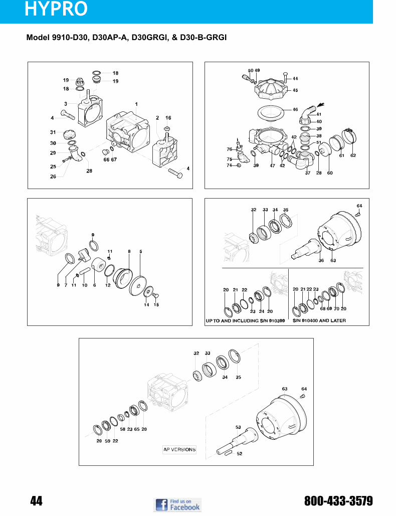
Model 9910-D30, D30AP-A, D30GRGI, & D30-B-GRGI
Figure 28NOTE: When ordering parts, giveQUANTITY, PART NUMBER,DESCRIPTION, and COMPLETEMODEL NUMBER. Referencenumbers are used ONLY to identifyparts in the drawing and are NOTto be used as order numbers.
Form L-1382 (09/10)

HYPRO
23
Ref. No. Qty.
18 422 128 230 139 242 449 151 167 1
9910-KIT1916O-Ring Kit
Ref. No. Qty.
18 419 4
9910-KIT1917Valve Kit
Model 9910-D30, D30AP-A, D30GRGI, & D30-B-GRGI
Ref. PartNo. Number Description Qty.1 9910-629011 Pump Body w/bolts 12 9910-620101 Right Head Assembly (DX) 13 9910-620102 Left Head Assembly (SX) 14 9910-621430 M12 x 55 Bolt 8
51 9910-620085 Diaphragm, Desmopan (Std.) 25 9910-620080 Diaphragm, Buna-N (Opt.) 26 9910-620120 Piston 27 9910-620140 Connecting Rod 28 9910-620110 Sleeve 29 9910-580470 Retainer Ring 210 9910-380300 Connecting Rod Pin 211 9910-380080 Ring Pin 412 9910-160230 Piston Ring 214 9910-1040180 Retaining Washer 215 9910-580360 Diaphragm Bolt 216 9910-180150 Nut 2
181,2,3 9910-620030 O-Ring 4
192 9910-1409050 Complete Valve Assembly 420 9910-111120 Retaining Ring 221 9910-620020 Cover 1
223 9910-620210 O-Ring 123 9910-620291 Retaining Ring 124 9910-620190 Bearing 125 9910-850850 M6 X 30 Bolt 226 9910-550331 Washer 2
283 9910-180101 O-Ring 229 9910-550030 Oil Sight Glass 1
303 9910-550040 O-Ring 131 9910-550056 Oil Sight Glass Cap 132 9910-620160 Spacer 133 9910-550060 Roller Bearing 134 9910-620130 Seal 135 9910-620330 Retaining Ring 136 9910-620170 Crankshaft 137 9910-620150 Suction Manifold 138 9910-550340 Threaded Adapter 1
393 9910-550350 O-Ring 240 9910-550242 Ring Nut 141 9910-550370 Hose Barb 1" 1
423 9910-390060 O-Ring 444 9910-621780 M8 X 40 Bolt 845 9910-629211 Upper Air Chamber 1
Ref. PartNo. Number Description Qty.
461 9910-550190 Accumulator Diaphragm, Buna-N 147 9910-622070 Lower Air Chamber Body 1
493 9910-650542 O-Ring 150 9910-180020 Air Valve 1
513 9910-390290 O-Ring 152 9910-620680 Key (AP-A Model) 153 9910-620172 Thru-Shaft 20 mm Dia. "AP Version" 153 9910-620174 Thru-Shaft 3/4" Dia. "AP Version" 158 9910-620630 Seal 159 9910-620021 Cover 160 9910-650660 Diaphragm Holder 161 9910-650670 Suction Diaphragm 162 9910-650690 Clamp 163 9910-1500350 PTO Shield 164 9910-820670 M10 X 16 Bolt 465 9919-620190 Bearing 166 2406-0023 Drain Plug, oil 1
673 9910-740290 O-Ring 168 9910-620930 Spacer 169 9910-620940 Spacer 170 9910-380230 Bearing 174 9910-390270 Nut 275 9910-450145 Flange 176 9910-110130 1/2" Fitting plus Hose Barb 1
1 Denotes Diaphragm Kit 9910-KIT17242 Denotes Valve Kit 9910-KIT19173 Denotes O-Ring Kit 9910-KIT1916
Ref. No. Qty.
5 218 446 1
9910-KIT1724Diaphragm Kit
Desmopan
Ref. No. Description Tightening TorqueIn. Lbs. Nm
4 Bolt 393.7 44.1
15 Bolt 262.5 29.4
16 Nut 350.0 39.2
25 M6 x 30 Bolt 87.5 9.8
44 M8 x 40 Bolt 175.0 19.6
64 M10 x 16 Bolt 87.5 9.8
74 Nut 175.0 19.6
Form L-1382 (09/10)

HYPRO
46 800-433-357926
Models 9910-D50, D50AP-A, & D50-B
Figure 30
Form L-1382 (09/10)

HYPRO
Ref. PartNo. Number Description Qty.1 9910-659011 Pump body 12 9910-650102 Left head SX 13 9910-320130 Nut 44 9910-650101 Right head DX 15 9910-160311 M 8 H 10 Nut 26 9910-650390 Retaining washer 2
72 9910-650085 Diaphragm Desmopan (Std.) 27 9910-650082 Diaphragm Buna-N (Opt.) 27 9910-65008T Diaphragm Buna-N with
Teflon Coating (Opt.) 28 9910-650090 Diaphragm support washer 210 9910-650190 Piston ring 212 9910-650121 Piston 213 9910-650071 Piston pin 214 9910-160691 Retainer ring 415 9910-650142 Connecting rod 216 9910-650130 Con rod rings 217 9910-650111 Sleeve 218 9910-200390 Retainer ring 119 9910-650040 Pump body cover 1
201 9910-650920 O-Ring 121 9910-650480 Retainer ring 122 9910-230330 Bearing 123 9910-161050 Retainer ring 124 9910-850850 Bolt 225 9910-550331 Washer 226 9910-650030 Oil Sight Glass 1
271 9910-180101 O-Ring 2
281 9910-550040 O-Ring 529 9910-550056 Sight Glass cap 130 9910-650160 Bearing spacer 131 9910-650200 Roller bearing 132 9910-1400150 Shaft seal 133 9910-650170 Shaft 1 34 9910-1400140 Flange 135 9910-961340 Washer 1
363 9910-659050 Complete valve 4372,3,1 9910-320030 O-Ring 4
38 9910-659204 Complete lower air chamber 1
Ref. PartNo. Number Description Qty.
392 9910-650520 Air chamber diaphragm 139 9910-65052T Air chamber diaphragm-Teflon(Opt.) 140 9910-659206 Upper air chamber 141 9910-180020 Air valve (includes #42) 1
421 9910-650542 Gasket 143 9910-621780 M8 x 40 Bolt 10
451 9910-390290 O-Ring 146 9910-650150 Suction manifold 147 9910-450120 Threaded adapter 148 9910-390290 O-Ring 149 9910-580060 Ring nut 150 9910-580040 Hose barb 1-1/4" 151 9910-650250 Key 153 9910-650171 Through-shaft (AP-A) 156 9910-650300 PTO shaft adapter 157 9910-680350 Bolt 458 9910-650490 Seal (AP-A model) 159 9910-650041 Spacer (AP-A model) 160 9910-650660 Diaphragm holder 161 9910-650670 Dampener diaphragm 162 9910-650690 Clamp 163 9910-1500350 Plastic shield 264 9910-820670 M10 x 16 Bolt 465 9910-659080 Complete bushing 266 2406-0023 Drain plug, oil 1
671 9910-740290 O-Ring 168 9910-1400110 Flange 169 9910-540290 M8 x 25 Bolt 270 9910-450145 Discharge flange housing 1
711 9910-550350 O-Ring 172 9910-110130 Hose barb and Nut 1/2" 174 9910-320392 Base 275 9910-750060 M12 x 65 Bolt 1081 9910-380241 Washer 382 9910-1200521 Spacer 383 9910-820361 Plug 1
1 Denotes O-Ring Kit 9910-KIT19192 Denotes Diaphragm Kit (Desmopan) 9910-KIT17253 Denotes Valve Kit 9910-KIT1920
Ref. No. Description Tightening TorqueIn. Lbs. Nm
3 Nut 271.0 29.45 Nut 171.4 19.643 Bolt 171.4 19.657 Bolt 171.4 19.664 Bolt 87.5 9.866 Plug 171.4 19.669 Plug 171.4 19.675 Bolt 435.0 49.0
27
Ref. No. Qty.
72 237 4392 1
Models 9910-D50, D50AP-A, & D50-B
Ref. No. Qty.
20 127 228 537 442 145 167 171 1
9910-KIT1919O-Ring Kit
Ref. No. Qty.
36 437 4
9910-KIT1920Valve Kit
9910-KIT1725Diaphragm Kit
Desmopan
Form L-1382 (09/10)

HYPRO
48 800-433-357924
Models 9910-D303, D303GRGI, D403, & D403GRGI
Figure 29
NOTE: When ordering parts, give QUANTITY, PART NUMBER, DESCRIPTION, and COMPLETE MODEL NUMBER. Reference numbers are used ONLY to identify parts in the drawing and are NOT to be used as order numbers.
1
2
3
4
5
8
13
12
11
10
14
25
26
48
49
6250
50
62
55
60
5857 58 59
5151
52
54
55
53
53
41
2728 29 30 31 32
373635
34
30
4438 39 40
42
33
1516
181819
22 21 20
6
9
78
Form L-1382 (09/10)
Not seeing the pump you are looking for!?
Don’t worry, we carry the full line of Hypro pumps and products- just call us to get the item you need for your project. Our sales staff is waiting for your call or e-mail to assist you in your search for parts and products. Contact us today!!!

HYPRO
Ref. PartNo. Number Description Qty.1 9910-800090 Retaining Bolt 32 9910-800350 Plate 3
31 9910-800085 Diaphragm Desmopan (Std.) 33 9910-800080 Diaphragm Buna-N (Opt.) 33 9910-80008T Diaphragm Buna-N with
Teflon Coating (Opt.) 34 9910-1880051 Sleeve (D303) 34 9910-1880050 Sleeve (D403) 35 9910-1880110 Piston Ring 36 9910-1880060 Piston 37 9910-1880120 Piston Pin 38 9910-380080 Pin Ring 69 9910-1880070 Connecting Rod 310 9910-1880101 Shaft (D303) 110 9910-1880100 Shaft (D403) 111 9910-1500350 Guard 112 9910-900270 Washer 413 9910-820670 M10 X 16 Bolt 414 9910-620330 Retaining Ring 115 9910-620130 Seal Ring 116 9910-550060 Roller Bushing 117 N/A18 9910-1880180 Connecting Rod Ring 219 9910-1880170 Spacer 120 9910-111120 Retaining Ring 121 9910-1461430 Bearing 122 9910-620291 Retaining Ring 125 9910-780060 M6 X 25 Bolt 326 9910-1880380 Seal 127 9910-1880020 Suction Manifold 1
283 9910-390290 O-Ring 129 9910-550340 Threaded Adapter 1
9910-KIT2389O-Ring Kit
9910-KIT2388Valve Kit
9910-KIT2423Diaphragm Kit
Desmopan
25
Ref. No. Qty.
28 130 233 134 135 139 151 953 657 262 6
Ref. No. Qty.
50 651 6
Models 9910-D303, D303GRGI, D403, & D403GRGI
Ref. PartNo. Number Description Qty.
303 9910-550350 O-Ring 231 9910-550242 Ring Nut 132 9910-550370 Elbow (Hose Barb) 1
333 9910-390201 O-Ring 1
343 9910-1880130 O-Ring 1
353 9910-390180 O-Ring 136 9910-550331 Washer 237 9910-1200440 M6 X 30 Bolt 238 9910-1040310 Oil Sight Glass 139 9910-650920 O-Ring 140 9910-1040322 Black Oil Tank Cap 141 9910-540290 M8 X 25 Bolt 242 9910-450145 Flange 144 9910-110130 1/2" Fitting and Hose 148 9910-800860 M8 X 55 Bolt 1249 9910-1880030 Head 3
502 9910-1889051 Complete Valve Assembly 6
512,3 9910-1140450 O-Ring 652 9910-1880010 Pump Body 1
533 9910-1880480 O-Ring 654 9910-280080 M8 X 60 Bolt 355 9910-1880040 Right Valve Cover 3
573 9910-740290 O-Ring 258 2406-0023 Drain Plug, oil 259 9910-1880080 Right Base 160 9910-1880090 Left Base 161 9910-620680 Key 162 9910-780050 O-Ring 6
1 Denotes Diaphragm Kit 9910-KIT24232 Denotes Valve Kit 9910-KIT23883 Denotes O-Ring Kit 9910-KIT2389
Ref. No. Qty.
3 3
Ref. No. Description Tightening TorqueIn. Lbs. Nm
1 Bolt 87.5 9.813 Bolt 87.5 9.825 Bolt 87.5 9.837 Bolt 87.5 9.841 Bolt 175.0 19.648 Bolt 175.0 19.654 Bolt 175.0 19.658 Plug 175.0 19.6
Form L-1382 (09/10)

HYPRO
50 800-433-3579
Ref. No. Description Tightening TorqueIn. Lbs. Nm
103 Bolt 171.4 19.6
104 Nut 171.4 19.6
107 Plug 171.4 19.6
112 Bolt 171.4 19.6
14
9910-KIT1741 Remote Mounting Kit includes mounting bracket and hose barb shown above.
9910-GS40GI Control Unitmounts directly on pump
Bypass Hose Barb —Connect directly to tank without restrictionsor ball valves.
Figure 14
Ref. PartNo. Number Description Qty.
831 9910-320433 Relief Valve Poppet Retainer 1
841 9910-320511 Gasket Seal O-Ring 1
851 9910-390140 Tension Spring Guide/Seal 186 9910-550460 Hose Barb 1/2" 187 9910-550450 Barb Nut 189 9910-180101 O-Ring 290 9910-550440 Threaded Adapter 191 9910-320410 Tension Spring Housing 192 9910-320480 Pin 193 9910-320460 Lever Guide 194 9910-320470 Pressure Release Lever 195 9910-320490 Locking Clip 196 9910-320450 Pressure Adjustment Nut 197 9910-320440 Threaded Guide 198 9910-110190 Tension Spring 198 9910-620810 Tension Spring (Opt.)
(under 100 psi) 1
Ref. PartNo. Number Description Qty.99 9910-230120 Tension Spring Retainer 1
100 9910-320406 Remote DischargeMounting Bracket 1
101 9910-450145 Discharge Flange Housing 1102 9910-110130 1/2" Hose Barb & Nut--(3/8" 1
9910-110131)103 9910-160660 M8 x 35 Bolt 2104 9910-390270 Nut 2105 9910-620220 Relief Valve Body 1106A 9910-KIT2497 Ball Valve (left) 1106B 9910-130491 Ball Valve (right) 1107 9910-130171 Plug 1
1091 9910-450110 Spring Holder 1110 9910-550350 O-Ring 1111 9910-550545 Pressure Gauge (Oil-filled) 1112 9910-180370 M8 x 25 Bolt 2
1131 9910-320420 Tension Spring 1
1141 9910-110122 Relief Valve Seat (Viton) (Std.) 1114 9910-110121 Relief Valve Seat (Urethane) 1
REPAIR & MAINTENANCE KIT AVAILABLE1 Control Unit Parts Kit No. 9910-KIT1757 consists of one each of:Ref. 83 Relief Valve Poppet Retainer, Ref. 84 Gasket Seal O-Ring,Ref. 85 Tension Spring Guide, Ref. 109 Spring Holder, Ref. 113Tension Spring and Ref. 114 Relief Valve Seat.
Model 9910-GS40GI Control UnitSub Assembly — 9910-1923 Includes parts 83-87, 89-99, 113 and 114.
93
92
91
89
87
86
90
95
96
97
98
99
112 102
101
103
100
111
104
106B105
107106A
110
114
113
8584
83
94
104110
109
Form L-1382 (09/10)

HYPRO
Old Style
Old Style
17
Ref. PartNo. Number Description Qty.1 9910-620561 O-Ring 12 9910-180030 M8 x 20 Bolt 13 9910-621000 Pump Adapter Flange 14 9910-620990 Bearing 15 9910-651620 Gear 16 9910-200231 Lock Washer 67 9910-160671 M10 x 25 Bolt 1" Long (D50) 37 9910-620470 M10 x 20 Bolt 3/4" Long (D30) 38 9910-620960 Gearbox Body 19 2406-0023 Plug 310 9910-740290 O-Ring 311 9910-540290 Bolt 412 9910-621010 M10 x 75 Bolt 413 9910-1140370 Vent Plug 114 9910-651610 Pinion Gear 115 9910-320240 Retaining Ring (Ext.) 216 9910-961780 Bearing 117 9910-961790 Retaining Ring (Int.) 118 9910-961800 Seal 119 9910-651000 5/16 x 24 UNF x 1 Bolt 420 9910-961900 3/8 x 16 UNC x 1-1/4 Bolt 421 9910-1320940 Engine Adapter Flange 122 9910-961770 Spacer 423 9910-650990 Key 124 9910-620950 Gasket 125 9910-650270 Gasket 127 9910-620980 Gear 128 9910-650400 Pinion Gear 1
Figure 16
2
1
3
5
67
2010
98
1312
10
9 10
11
4
1415
1517
18
19
Gearbox 9910-KIT1640Ref. PartNo. Number Description Qty.1 9910-620561 O-Ring 12 9910-180030 M8 x 20 Bolt 13 9910-621000 Pump Adapter Flange 14 9910-620990 Bearing 15 9910-651620 Gear 16 9910-200231 Lock Washer 67 9910-620470 M10 x 20 Bolt 38 9910-620960 Gearbox Body 19 2406-0023 Plug 210 9910-740290 O-Ring 211 9910-651000 5/16 x 24 UNF x 1 Bolt 412 9910-621010 M10 x 75 Bolt 413 9910-1140370 Vent Plug 114 9910-621660 Pinion Gear 115 9910-320240 Retaining Ring (Ext.) 216 9910-961780 Bearing 117 9910-961790 Retaining Ring (Int.) 118 9910-961800 Seal 119 9910-881090 Key 120 9910-620950 Gasket 127 9910-620980 Gear 128 9910-620970 Pinion Gear 1
Figure 17
2
Gearbox 9910-KIT1642
1
3
5
67
10911
24
9108
1312
23
22
21
10
9
41415
1615
17
18
19
20
25
Ref. No. Description Tightening TorqueIn. Lbs. Nm
2 Bolt 218.7 24.57 Bolt 171.4 19.69 Plug 171.4 19.6
11 Bolt 218.7 24.512 Bolt 218.7 24.5
9
16
27
28
27
Ref. No. Description Tightening TorqueIn. Lbs. Nm
2 Bolt 218.7 24.57 Bolt 171.4 19.69 Plug 171.4 19.6
11 Bolt 218.7 24.512 Bolt 218.7 24.519 Bolt 218.7 24.520 Bolt 218.7 24.5
28
Form L-1382 (09/10)
HYPRO
52 800-433-3579
4
7
10
15
14
1312
11
9
6
8
6
3 2
15
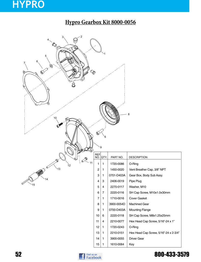
1 1 1720-0086 O-Ring
2 1 1450-0020 Vent Breather Cap, 3/8” NPT
3 1 0701-D403A Gear Box, Body Sub Assy.
4 3 2406-0019 Pipe Plug
5 4 2270-0117 Washer, M10
6 7 2220-0116 SH Cap Screw, M10x1.0x30mm
7 1 1710-0016 Cover Gasket
8 1 3900-0054D Machined Gear
9 1 0700-D403A Mounting Flange
10 6 2220-0118 SH Cap Screw, M8x1.25x25mm
11 4 2210-0077 Hex Head Cap Screw, 5/16”-24 x 1”
12 1 1720-0243 O-Ring
13 1 2210-0151 Hex Head Cap Screw, 5/16”-24 x 2-3/4”
14 1 3900-0055 Driver Gear
15 1 1610-0064 Key
REF.NO. QTY. PART NO. DESCRIPTION
Hypro Gearbox Kit 8000-0056
HYPRO
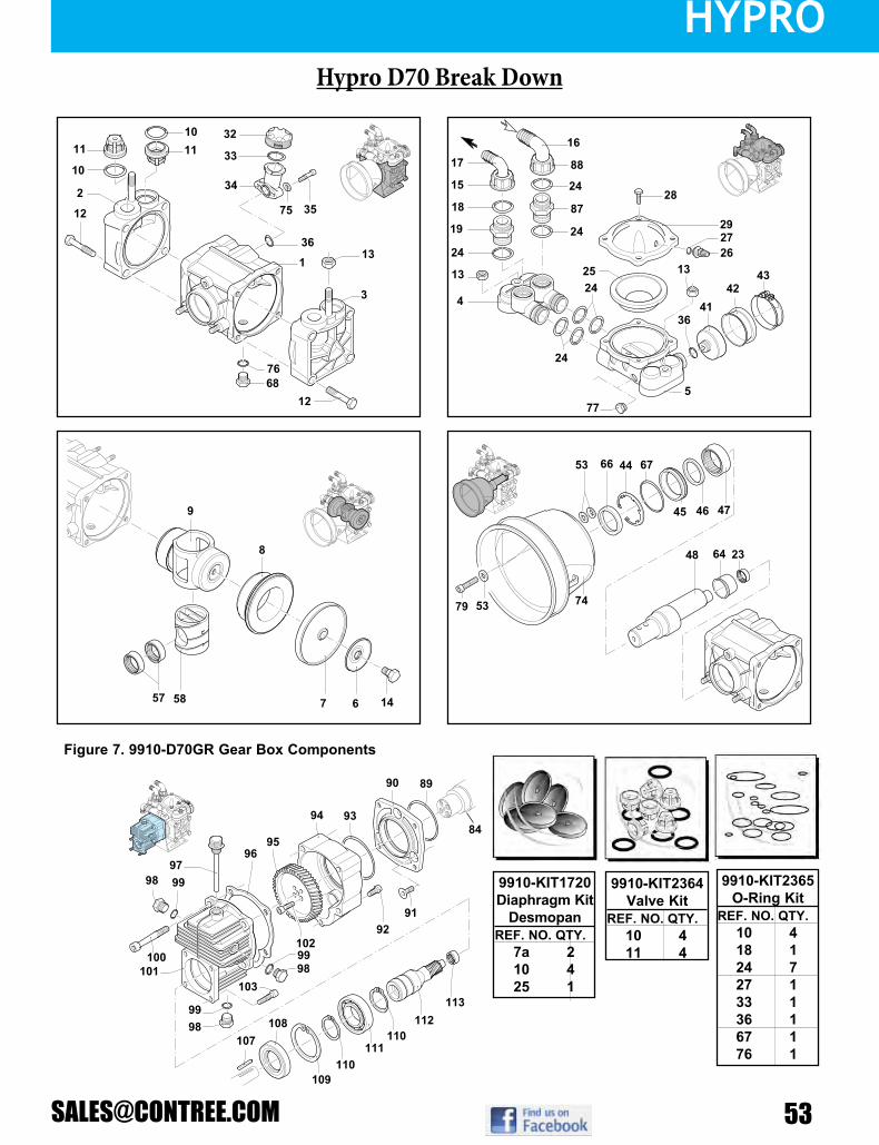
Parts Illustrations for Models 9910-D70 and 9910-D70GRFigure 6. Parts Illustrations for Model 9910-D70
Figure 7. 9910-D70GR Gear Box Components
32
34
75
36
3
7668
12
57
9192
89
95
94
103
111
109
108107
110
110112
113
98
98
98
100
9796
99
99
99
102
101
8493
90
79 53 74
48 64 23
46
44 67
45
6653
47
58 14
9
7
8
6
4
15
18
19
13
16
24
8728
2524
13
3641
4243
2726
29
5
24
77
88
24
24
17
1
12
2
11 11
10
10
13
35
33
L-1381 (Rev. B)
9910-KIT2365O-Ring Kit
REF. NO. QTY.10 418 124 727 133 136 167 176 1
9910-KIT2364Valve Kit
REF. NO. QTY.10 411 4
9910-KIT1720Diaphragm Kit
DesmopanREF. NO. QTY.
7a 210 425 1
Hypro D70 Break Down

HYPRO
54 800-433-3579
REF PART NUMBER DESCRIPTION QTY REF PART NUMBER DESCRIPTION QTY
1 2 3
9910-550011 9910-550101 9910-550102
Pump Body with bolts Right head DXLeft head SX
1 1 1
52 53 57
9910-200233 9910-320621 9910-550280
WasherWasherBearing
2 5 2
4 5 6
9910-550150 9910-559200 9910-580370
Manifold Accumulator manifold
Plate
1 1 2
58 64 66
9910-550140 9910-550160 9910-550491
CylinderSpacer
Seal ring
1 1 1
7 7a 8
9910-550080 9910-550085 9910-550110
Diaphragm (Buna) Optional Diaphragm (Desmopan) Standard
Sleeve
2 2 2
67 68 74
9910-650920 2406-0023
9910-1500350
O-ring Oil drain plug
Shield
1 1 1
9 10 11
9910-550120 9910-320030 9910-759051
Piston O-ring
Complete valve assembly
1 4 4
75 76 77
9910-550332 9910-740290 9910-330173
WasherO-ringPlug
2 1 1
12 13 14
9910-551040 9910-180152 9910-580360
M10 x 55 Bolt Nut
Diaphragm bolt
8 4 2
79 84 87
9910-620472 9910-550175 9910-450120
M10 x 20 Bolt Shaft
Threaded adapter
1 1 1
15 16 17
9910-550880 9910-580040 9910-550370
Ring nutElbow 1-1/4”
Elbow 1”
1 1 1
88 89 90
9910-550870 9910-580230 9910-550920
Ring nutO-ringFlange
1 1 1
18 19 23
9910-550350 9910-550340 9910-550310
O-ring Threaded adapter
Roller bearing
1 1 1
91 92 93
9910-550950 9910-180030 9910-620561
Bolt Bolt
O-ring
3 1 1
24 25 26
9910-390290 9910-550190 9910-550300
O-ring Accumulator diaphragm
Air valve
7 1 1
94 95
9910-621000 9910-550930
Gear cap Gear
1 1
27 28 29
9910-650542 9910-550680 9910-559204
O-ring Bolt
Upper air chamber
1 4 1
96 97 98
9910-620950 9910-1140370 9910-1980740
Gasket Oil Plug & O-ring
Plug
1 1 3
32 33 34
9910-550057 9910-550040 9910-550030
Sight glass cap O-ring
Oil sight glass
1 1 1
99 100 101
9910-740290 9910-621010 9910-620960
O-ring Bolt
Gear box
3 4 1
35 36 41
9910-850851 9910-180101 9910-650660
Bolt O-ring
Diaphragm holder
2 2 1
102 103 107
9910-540290 9910-651000 9910-881090
BoltBoltKey
4 4 1
42 43 44 45
9910-650670 9910-650690 9910-200391 9910-550470
DiaphragmClamp
Retainer ringSeal ring
1 1 1 1
108 109 110
9910-961800 9910-961790 9910-320240
Seal ring Circlip Circlip
1 1 2
46 47 48
9910-550070 9910-550060 9910-550170
Spacer ringRoller bushing
Shaft
1 1 1
111 112 113
9910-961780 9910-621660 9910-620990
BearingPinion
Bearing
1 1 1
Model Number Description255-223 50 Mesh screen, 1⁄2” Barb Inlet x 1⁄2 NPSM Female Outlet255-313 50 Mesh screen, 1⁄2” NPSM Male Inlet x 1⁄2 NPSM Female Outlet, EPDM O-ring255-323 50 Mesh screen, 1⁄2” Barb Inlet x 1⁄2 NPSM Female Outlet, EPDM O-ring255-646 50Meshscreen,3⁄8”x3⁄8”MNPTPoly/Nylon,Viton®O-ring255-457 50 Mesh screen, 3⁄8” x 3⁄8” MNPT Poly/Nylon, Buna O-ring255-568 50 Mesh screen, 3⁄8” x 3⁄8” MNPT Poly/Nylon, EPDM O-ring255-613 50Meshscreen,1⁄2”NPSMMaleInletx1⁄2NPSMFemaleOutlet,Viton®O-ring255-623 50Meshscreen,1⁄2”BarbInletx1⁄2NPSMFemaleOutlet,Viton®O-ring255-413 50 Mesh screen, 1⁄2” NPSM Male Inlet x 1⁄2 NPSM Female Outlet, Buna O-ring255-423 50 Mesh screen, 1⁄2” Barb Inlet x 1⁄2 NPSM Female Outlet, Buna O-ring
SHURflo Bowl-Strainers
Hypro D70 Parts List

HYPRO
Bypass 12 VDC
Auto Demand 12 VDC
Auto Demand115 VAC Pump
No Control 12 VDC
Power Twin Auto Demand
12 VDC
Flex Impeller 12 VDC
AquaTiger Bronze
AquaTiger Stainless
Model Number Max GPM
Max PSI
Max Draw Power Port
Size Description Est Ship Wt
806-543-250 1.4 50 5.5 Amps
12 VDC
3/8” FNPT
Bypass Pump with Reversed Pump head: Viton®valves,Santoprene®diaphragm,
45 PSI internal bypass4 lbs
8000-533-236 1.4 60 0.64 Amps
115 VAC
3/8” FNPT
StandardDemandPump:Viton®valves,Santoprene®diaphragm,60PSIdemand
switch5 lbs
8000-533-250 1.4 50 0.54 Amps
115 VAC
3/8” FNPT
BypassPump:Viton®valves,Santoprene®diaphragm, 45 PSI Internal Bypass 4 lbs
8007-543-836 1.8 50 6.4 Amps
12 VDC
3/8” FNPT
Demand Pump w/Electrical Package: Viton®valves,Santoprene®diaphragm,60 PSI Demand Switch, Manual on/off
switch 2 pin connector, FUSED
5 lbs
2087-593-435 (Single Pump) 2087-593-135 (Pack of 6) 3.0 50 8.0
Amps12
VDC½”
MSPT
StandardDemandPump:Viton®valves,Santoprene®diaphragm,45PSIdemand
switch5 lbs
2088-343-435 (Single Pump) 2088-343-135 (Pack of 6) 3.0 40 7.7
Amps12
VDC½”
MSPT
StandardPump:Viton®valves,Santoprene®diaphragm,45PSIdemand
switch5 lbs
2088-343-500 3.3 50 10.1 Amps
12 VDC
½” MSPT
FrontAdapterPump:Viton®valves,Santoprene®diaphragm,1⁄4”FPT
adapter mounted on switch port, no demand switch
4 lbs
4111-035 6.3 40 17.2 Amps
12 VDC
½” MSPT
Viton®valves,Santoprene®diaphragm,45 PSI demand switch, manifold with
5⁄8” barb ports6 lbs
9700B (Bronze) 19.0 7 11 Amps
12 VDC
¾” NPT
Bronze centrifugal pump housing, Bronze impeller, electric motor, Fluid
temperatures up to 140°F, Viton lip-type seal
6 lbs
9700S (Stainless) 19.0 7 11 Amps
12 VDC
¾” NPT
Stainless Steel centrifugal pump housing, Stainless Steel impeller, electric motor, Fluid temperatures up to 140°F,
Mechanical Seal
6 lbs
SHURflo Pumps
5059 Series 12 VDC
SHURflo Swivel FittingsModel Number Description
064 803400 Swivel 1/2” Elbow064 806000 Swivel 3/8” Elbow064 807000 Swivel 1/2” Straight064 807100 Swivel 3/8” Straight

ACE
56 800-433-3579
1-3/8” 6 spline600 RPM
Standard Shaft
1-3/8” 6 spline600 RPM
Quick Couple
1-3/8” 20 spline1000 RPM
Locking Collar
1-3/8” 21 spline1000 RPM
Locking Collar
1” Stub ShaftFor trailing sprayer
with tumblerod drive
Ace PTOC Centrifugal Pump
Model Number Shaft Max RPM
Max GPM
GPM @ 30 PSI
GPM @ 40 PSI
GPM @ 60 PSI
Max PSI Inlet Size Outlet Size Est. Shipping
Wt
PTOC-600-6SP 1-3/8” 600 RPM Female PTO shaft bolted 600 65 64 62 46 80 1¼” 1” 45
PTOC-600-QC 1-3/8” 600 RPM Female PTO Quick Couple 600 65 64 62 46 80 1¼” 1” 46
PTOC-600-B 1” Male Stub Shaft 600 65 64 62 46 80 1¼” 1” 42
PTOC-1000-21SP 1-3/8” 1000 RPM Female PTO shaft bolted 1000 65 64 62 46 80 1¼” 1” 43
PTOC-1000-20SP 1-3/8” 1000 RPM Female PTO Quick Couple 1000 65 64 62 46 80 1¼” 1” 45
PTOC-1000-B 1” Male Stub Shaft 1000 65 64 62 46 80 1¼” 1” 40
PTOC-150-600-6SP
1-3/8” 600 RPM Female PTO shaft bolted 600 100 100 95 82 110 1½” 1¼” 51
PTOC-150-600-QC
1-3/8” 600 RPM Female PTO Quick Couple 600 100 100 95 82 110 1½” 1¼” 51
PTOC-150-600-B 1” Male Stub Shaft 600 100 100 95 82 110 1½” 1¼” 52
PTOC-150-1000-21SP
1-3/8” 1000 RPM Female PTO shaft bolted 1000 100 100 92 85 110 1½” 1¼” 48
PTOC-150-1000-20SP
1-3/8” 1000 RPM Female PTO Quick Couple 1000 100 100 92 85 110 1½” 1¼” 50
PTOC-150-1000-B 1” Male Stub Shaft 1000 100 100 92 85 110 1½” 1¼” 45
FMC-MIA PUMP ONLY 600/ 1000 *** *** *** *** *** 1¼” 1” 18
FMC-150-MIA 150 PUMP ONLY 600/ 1000 *** *** *** *** *** 1½” 1¼” 23

ACE
Ace PTOC 600/1000 Centrifugal Pump Repair Parts
PARTS LIST
# Not shown in exploded view drawing.
REF. # PART # EDP # DESCRIPTION REQ.1 BAC-10-S 40190 Shaft, 1” Tumblerod stub 12 BAC-10-175-20SP 40180 Shaft, 1-3/4” 20 Tooth PTO spline, includes BAC-11-175 13 BAC-10-21SP 40220 Shaft, 1 3/8” 21 Tooth PTO spline, includes BAC-11 14 40960 40960 Nut, 3/8” NC, jam 35 BAC-40 40940 Set screw, 3/8” NC slotted 36 BAC-11-175 40236 Locking collar, split ring (for BAC-10-175-20SP shaft) 17 BAC-11 40235 Locking collar, split ring (for BAC-10-21SP shaft) 18 BAC-11-1 40237 Set screw (for BAC-11 and BAC-11-175 locking collar) 19 BAC-10-6SP-QC 40210 Shaft, 1-3/8” 6 Tooth PTO spline, for quick coupler 110 BAC-83-QC 41470 Ball for quick coupler 311 BAC-82-QC 41460 Spring for quick coupler 112 BAC-81-QC 41450 Ball retainer sleeve for quick coupler 113 41250 41250 Cap screw, 5/16” NC x 3-1/4”, hex head 114 41300 41300 Set screw, 3/8” NC x 5/8”, allen head 215 BAC-30-10-M 40750 Pulley, 6.375” P.D. x 2” Bore, Poly-V (for PTOC-1000-21SP & -B) 115 BAC-30-175 40745 Pulley, 6.375” P.D x 2-3/8” Bore, Poly-V (for PTOC-1000-20SP) 116 BAC-63 41260 Nut, 5/16” NC, self locking, for tumblerod drive 117 BAC-34 40830 Snap ring, internal, BAC-15 bearing housing 218 BAC-27 40520 Name plate 119 BAC-35 40840 Snap ring, external, BAC-10 drive shaft 120 BAC-31-1 40781 Bearing, sealed, BAC-10 drive shaft 221 BAC-38-1 40905 Spacer, bearing, BAC-10 shaft 122 BAC-44 40990 Washer, 3/8” locking 223 BAC-45 41010 Nut, hex, 3/8” NC 224 BAC-15 40340 Housing, PTO drive shaft bearing housing 124 BAC-15-B 40370 Housing, tumblerod drive shaft bearing housing with mounting base 125 BAC-10-6SP 40200 Shaft, 1-3/8” 6 Tooth PTO spline drive 126 BAC-51 41090 Shaft, 3/8” x 1/2” x 1-1/2” key, PTO drive shaft 127 40960 40960 Nut, jam, 3/8” NC 328 BAC-40 40940 Set screw, 3/8” NC, slotted 329 BAC-30-10 40740 Pulley, 10.6” P.D. x 2” bore Poly-V pulley, 10 groove (for PTOC-600) 130 41300 41300 Set screw, 3/8” NC x 5/8”, allen head 2
31j BAC-28-10 40610 Belt, Poly-V, 10 groove (for PTOC-600) 131k BAC-28-10-M 40620 Belt, Poly-V, 10 groove (for PTOC-1000) 132 BAC-53 41110 Pipe plug, 1/8” NPT 332 41120 41120 Pipe plug, 1/8” NPT, stainless steel (optional) 333 BAC-12 40250 Volute 1-1/4” x 1”, cast iron 134 BAC-26-CI 40432 Impeller, cast Iron, left hand thread (optional) 134 BAC-26-VALOX 40430 Impeller, Valox, left hand thread 1
35jklm BAC-4-A 40005 O-ring, volute seal 136m BAC-7SC 40152 Seal, silicon carbide mechanical (includes 40160) (optional) 1
36jkl BAC-7V 40151 Seal, Viton, mechanical (includes 40160 O-ring) 136Ajklm 40160 40160 O-ring for mechanical seal 1
37 BAC-42 40970 Cap screw, 3/8” NC x 2” hex head 238 BAC-43 40980 Washer, 3/8” flat 239 BAC-14-MIA 40290 Mounting frame, machined for idler arm 140 BAC-15-PIN 40799 Alignment pin 241 40950 40950 Cap screw, 3/8” NC x 3/4” hex head 441 40930 40930 Cap screw, 3/8” NC x 3/4” hex head, stainless steel (optional) 442 BAC-54 41130 Slinger 143 BAC-33 40810 Snap ring, internal, for mounting frame 244 BAC-37 40870 Bearing, sealed, for pump shaft 245 BAC-32 40790 Snap ring, external, for driven pump shaft 246 BAC-32-S 40795 Spacer for pump shaft 147 BAC-6-SS 40070 Shaft, 5/8”, left hand course thread, stainless steel 148 BAC-50 41080 Key, 3/16” x 3/16” x 1-1/4” 149 BAC-57 41180 Cap screw, 5/16” NC x 5/16” allen head, for BAC-29-10 pulley 250 BAC-29-10-1.50 40680 Pulley, 1.5” P.D. x 5/8” bore, Poly-V, 10 groove 151 BAC-5 40030 Spring, idler mounted torsion 152 BAC-13 40270 Idler arm 153 BAC-36 40850 Snap ring, external, BAC-13 idler arm 154 BAC-46 41020 Spacer, 5/8” 155 41070 41070 Retainer ring 156 BAC-55 41140 Idler bearing and outer roller assembly 157 BAC-47 41040 Cap screw, 5/8” NC x 2 1/8” hex head idler 1# BAC-52 41100 Chain, 1/4” cold shut, torque anchor 1# BAC-58 41190 Zerk fitting, 1/4” NPT, for idler arm 1# BAC-55-A 41150 Idler arm assembly (includes 52 through 57 and BAC-58) -# BGKB 52610 Belt and shaft guard kit for all PTOC pumps -j RK-PTOC-600 51150 Repair kit for 600 RPM models, includes belt, seal, and “O” ring -k RK-PTOC-1000 51250 Repair kit for 1000 RPM, includes belt, seal, and “O” ring -l RK-FMC 52700 Repair kit for pump only, includes seal, and “O” ring -m RK-FMCSC 52706 Repair kit for pump only, includes silicon carbide seal, and “O” ring -# FMC-MIA 47000 Pump end only, machined to accept idler arm -

ACE
58 800-433-3579
Ace PTOC - 150 Centrifugal Pump Repair Parts
PARTS LISTREF. # PART # EDP # DESCRIPTION REQ.
1 BAC-10-S 40190 Shaft, 1” Tumblerod stub 12 BAC-10-175-20SP 40180 Shaft, 1-3/4” 20 Tooth PTO spline, includes BAC-11-175 13 BAC-10-21SP 40220 Shaft, 1-3/8” 21 Tooth PTO spline, includes BAC-11 14 40960 40960 Nut, jam, 3/8” NC 35 BAC-40 40940 Set screw, slotted, 3/8” NC 36 BAC-11-175 40236 Locking collar, split ring (for BAC-10-175-20SP shaft) 17 BAC-11 40235 Locking collar, split ring (for BAC-10-21SP shaft) 18 BAC-11-1 40237 Set screw (for BAC-11 and BAC-11-175 locking collar) 19 BAC-10-6SP-QC 40210 Shaft, 1-3/8” 6 Tooth PTO spline, for quick coupler 1
10 BAC-83-QC 41470 Ball for quick coupler 311 BAC-82-QC 41460 Spring for quick coupler 112 BAC-81-QC 41450 Sleeve, ball retainer, for quick coupler 113 41250 41250 Cap screw, hex head, 5/16” NC x 3-1/4” 114 41300 41300 Set screw, allen head, 3/8” NC x 5/8” 215 BAC-30-10-M-150 40751 Pulley, 7.9” P.D. x 2” Bore, Poly-V, (for PTOC-150-1000-21SP) 115 BAC-30-175-150 40746 Pulley, 7.9”P.D x 2-3/8” Bore, Poly-V, (for PTOC-150-1000-20SP) 116 BAC-63 41260 Nut, self locking, 5/16” NC, for tumblerod drive 117 BAC-34 40830 Snap ring, internal, BAC-15 bearing housing 218 BAC-27 40250 Name plate 119 BAC-35 40840 Snap ring, external, BAC-10 drive shaft 120 BAC-31-1 40781 Bearing, sealed, BAC-10 drive shaft 221 BAC-38-1 40905 Spacer, BAC-10 shaft 122 BAC-44 40990 Washer, locking, 3/8” 223 BAC-45 41010 Nut, hex, 3/8” NC 224 BAC-15 40340 Housing, PTO drive shaft bearing 124 BAC-15-B 40370 Housing, tumblerod drive shaft bearing housing with mounting base 125 BAC-10-6SP 40200 Shaft, 1-3/8” 6 Tooth PTO spline 126 BAC-51 41090 Key, 3/8” x 1/2” x 1-1/2”, PTO drive shaft 127 40960 40960 Nut, jam, 3/8” NC 328 BAC-40 40940 Set screw, slotted, 3/8” NC 329 BAC-30-10-150 40741 Pulley, 11.6” P.D. x 2” Bore, Poly-V, 10 groove (for 600 RPM models) 130 41300 41300 Set screw, allen head, 3/8” NC x 5/8” 2
31j BAC-28-10-150 40611 Belt, Poly-V, 10 groove (for PTOC-150-600) 131k BAC-28-10M-150 40621 Belt, Poly-V, 10 groove (for PTOC-150-1000) 132 BAC-53 41110 Pipe plug, 1/8” NPT 332 41120 41120 Pipe plug, 1/8” NPT, stainless steel (optional) 333 BAC-12-150 40255 Volute, 1-1/2” x 1-1/4”, cast iron 134 BAC-23-A 40391 Nut, lock, 3/8” NF hex, cad plated 134 BAC-23-B-SS 40393 Nut, 3/8” NF, stainless steel (standard on -SS models) 1
35jklm BAC-24-HYD-SS 40400 Washer, 3/8”, stainless steel 135 BAC-24-B-SS 42702 Washer, 3/8”, stainless steel, vibration proof (standard on -SS models) 136 BAC-26-150-P 40446 Impeller, thermoplastic, with keyway 136 BAC-26-150-CI 40445 Impeller, cast iron, with keyway(optional) 136 BAC-26-150-PI 40448 Impeller, polypropylene, with keyway(optional) 1
37jklm BAC-4-150 40015 O-ring volute seal 138jkl BAC-7V 40151 Seal, Viton mechanical seal (includes 40160 “O” Ring) 1
38m BAC-7SC 40152 Seal, silicon carbide mechanical seal (includes 40160) (optional) 138Ajklm 40160 40160 O-ring for mechanical seal 1
39 BAC-42 40970 Cap screw, hex head, 3/8” NC x 2” 240 BAC-43 40980 Washer, flat, 3/8” 241 BAC-14-150-MIA 40308 Mounting frame, machined for idler arm 142 BAC-15-PIN 40799 Alignment pin 243 40930 40930 Cap screw, hex head, 3/8” NC x 3/4”, stainless steel (optional) 443 40950 40950 Cap screw, hex head, 3/8” NC x 3/4” 444 BAC-54 41130 Slinger 145 BAC-33 40810 Snap ring, internal, for mounting frame 246 BAC-37 40870 Bearing, sealed, for pump shaft 247 BAC-32 40790 Snap ring, external, for driven pump shaft 248 BAC-32-S 40795 Spacer for pump shaft 149 BACH-25 40420 Key, for impeller, 1/8” x 1/8” x 1/2” 150 BAC-6-150/200-SS 40056 Shaft, 5/8”, with keyway, stainless steel 151 BAC-50 41080 Key, 3/16” x 3/16” x 1-1/4” 152 BAC-29-10-1.35 40675 Pulley, 1.35” P.D. x 5/8” Bore, Poly-V, 10 groove(PTOC-150-600) 152 BAC-29-10-1.7 40681 Pulley, 1.7” P.D. x 5/8” Bore, Poly-V, 10 groove(PTOC-150-1000) 153 BAC-57 41180 Set screw, allen head, 5/16” NC x 5/16”, for BAC-29-10 pulley 254 BAC-5-150 40035 Spring, idler mounted torsion, for 150 series 155 BAC-13 40270 Idler arm 156 BAC-36 40850 Snap ring, external, BAC-13 idler arm 157 BAC-46 41020 Spacer, 5/8” 158 41070 41070 Retainer ring 159 BAC-55 41140 Idler bearing and outer roller assembly 160 BAC-47 41040 Cap screw, hex head, 5/8” NC x 2-1/8”, idler 1# BAC-52 41100 Chain, 1/4” cold shut, torque chain anchor 1# BAC-58 41190 Zerk fitting, 1/4” NPT, for idler arm 1# BAC-55-A 41150 Idler arm assembly (includes 55 through 60 and BAC-58) -# BGKB 52610 Belt and shaft guard kit for all PTOC pumps -j RK-PTOC-150-600 51155 Repair kit for 600 RPM models, includes belt, seal, and O-ring -k RK-PTOC-150-1000 51255 Repair kit for 1000 RPM, includes belt, seal, and O-ring -l RK-FMC-150 52710 Repair kit for pump only, includes seal, and O-ring -m RK-FMCSC-150 52711 Repair kit for pump only, includes silicon carbide seal, and O-ring -# FMC-150-MIA 47008 Pump end only, machined to accept idler arm -
# Not shown in exploded view drawing.

ACE
Model Number Hydraulic GPM Max
Max GPM
GPM @ 30 PSI
GPM @ 40 PSI
GPM @ 60 PSI
Max PSI Inlet Size Outlet Size Est Shipping
Wt
FMC-HYD-202 2 GPM 85 85 85 76 100 1-1/4” 1” 25 lbsFMC-HYD-203 3 GPM 85 85 85 76 100 1-1/4” 1” 26 lbsFMC-HYD-204 4 GPM 85 85 85 76 100 1-1/4” 1” 26 lbsFMC-HYD-206 7 GPM 85 85 85 76 100 1-1/4” 1” 27 lbsFMC-HYD-210 10 GPM 85 85 85 76 100 1-1/4” 1” 27 lbsFMC-HYD-310 16 GPM 85 85 85 76 100 1-1/4” 1” 33 lbsFMC-150-HYD-206 7 GPM 135 132 128 119 120 1-1/2” 1-1/4” 31 lbs
FMC-150F-HYD-206 7 GPM 145 140 132 118 120 1-1/2” - 220 Flange
1-1/4” - 200 Flange 31 lbs
FMC-150FS-HYD-206 7 GPM 145 140 132 118 120 1-1/2” - 220 Flange
1-1/4” - 200 Flange 31 lbs
FMC-150F-HYD-304 11 GPM 155 140 132 118 130 1-1/2” - 220 Flange
1-1/4” - 200 Flange 31 lbs
FMC-200-HYD-210 10 GPM 200 200 200 170 80 2” 1-1/2” 33 lbsFMC-200-HYD-304 11 GPM 200 200 200 170 120 2” 1-1/2” 38 lbsFMC-200SS-HYD-304 11 GPM 200 200 200 170 120 2” 1-1/2” 36 lbsFMC-200-HYD-310 16 GPM 200 200 200 170 120 2” 1-1/2” 38 lbsFMC-200F-HYD-304 11 GPM 240 240 219 175 120 300 Flange 220 Flange 38 lbsFMC-650-HYD 14 GPM 140 149 149 148 160 1-1/2” 1-1/4” 39 lbs
FMC-650F-HYD 14 GPM 170 189 188 186 160 1-1/2” - 220 Flange
1-1/4” - 200 Flange 39 lbs
FMCWS-650F-HYD 14 GPM 170 189 188 186 160 1-1/2” - 220 Flange
1-1/4” - 200 Flange 49 lbs
Model Number Hydraulic GPM Max
Max GPM
GPM @ 90 PSI
GPM @ 100 PSI
GPM @ 120 PSI
Max PSI Inlet Size Outlet Size Est Shipping
Wt
FMC-750F-HYD-M22 18 GPM 290 290 290 260 150 300 Flange 220 Flange 72 lbsFMC-750F-HYD-M25 20 GPM 290 290 290 260 150 300 Flange 220 Flange 72 lbsFMC-850F-HYD 23 GPM 325 325 310 262 150 300 Flange 300 Flange 80 lbs
Ace Hydraulic Centrifugal Pump
Model Number without hydraulic motor Series of Pump Inlet Size Outlet Size Est. Shipping
Wt
FMC-HYD-LM FMC-HYD-2XX models 1¼” 1” 18 lbsFMC-HYD-310-LM FMC-HYD-310 models 1¼” 1” 18 lbsFMC-150-HYD-LM FMC-150-HYD-206 models 1½” 1¼” 18 lbs
FMC-150F-HYD-LM FMC-150F-HYD-206 models 220 Flange 200 Flange 18 lbsFMC-200-HYD-LM FMC-200-HYD-210 models 2” 1½” 23 lbs
FMC-200-HYD-300-LM FMC-200-HYD-3XX models 2” 1½” 23 lbsFMC-200F-HYD-300-LM FMC-200-HYD-210 models 1¼” 1” 23 lbs
FMC-650-HYD-LM FMC-650-HYD models 220 Flange 200 Flange 32 lbsFMC-750F-HYD-LM FMC-750F-HYD-XXX models 300 Flange 220 Flange 65 lbs
Ace Hydraulic Centrifugal Pump Less Motor

ACE
60 800-433-3579
FMC-HYD
Ace Pump Corporation 1650 Channel Avenue Memphis, TN 38113www.AcePumps.com Phone: 901-948-8514 Fax: 901-774-6147
Ace Form # FMC-HYDRevised 02/09
9
11
12 1314 13
12 11
16
18
87
5
6
1
15
2
34
106A
23
22
2425
21
26
19
20
17
8
20
1819
REF. # PART NUMBER EDP # DESCRIPTION REQ.1 BAC-53 41110 Pipe plug 41 41120 41120 Pipe plug, stainless steel (optional) 42 BAC-12 40250 Volute, 1-1/4” x 1”, cast iron 13 BAC-23-A 40391 Nut, 3/8” NF, cad plated 13 BAC-23-A-SS 40392 Nut, 3/8” NF, stainless steel (optional) 1
4 BAC-24-HYD-SS 40400 Washer, 3/8” star, stainless steel 15 BAC-26-HYD-VALOX 40440 Impeller, Valox, keyway 15 BAC-26-HYD-CI 40442 Impeller, cast iron, keyway (optional) 1
6 BAC-7V 40151 Seal, carbon/ceramic/Viton (includes 40160 O-Ring) 16 BAC-7SC 40152 Seal, silicon carbide/Viton (includes 40160 O-Ring) (optional) 1
6A 40160 40160 O-ring, shaft seal 17 BAC-4A 40005 O-ring, body seal 1
8 BAC-14-HYD 40300 Mounting frame, cast iron (for 200 Series hydraulic motor) 18 BAC-14-HYD-300A 40314 Mounting frame, cast iron (for 300A Series hydraulic motor) 19 40950 40950 Cap screw, 3/8” NC x 3/4” hex head 49 40930 40930 Cap screw, 3/8” NC x 3/8” hex head, stainless steel (optional) 4
10 BAC-54 41130 Slinger 111 BAC-33 40810 Snap ring, internal, BAC-14 mounting frame 212 BAC-37 40870 Ball Bearing, sealed, BAC-6 shaft 213 BAC-32 40790 Snap ring, external, BAC-6 shaft 214 BAC-32-S 40795 Spacer for BAC-6 shaft 115 BACH-25 40420 Key, 1/8” x 1/8” x 1/2” 116 BAC-6-HYD-SS 40061 Shaft, 5/8” diameter, keyway and tang slot, stainless steel 117 BAC-75-HYD-204 41370 Hydraulic motor, 4 GPM (includes parts 18 - 25) 117 BAC-75-HYD-210 41375 Hydraulic motor, 10 GPM (includes parts 18 - 25) 118 S200 40161 Seal support spacer for 200 Series HYD motor 118 S300 40162 Seal support spacer for 300 Series HYD motor 119 BAC-75-HYD-204N 41433 Hydraulic motor, 4 GPM (motor only - no external fittings) 119 BAC-75-HYD-210N 41434 Hydraulic motor, 10 GPM (motor only - no external fittings) 119 BAC-75-HYD-310 41378 Hydraulic motor, 16 GPM (310A motor effective March 2006) 120 41253 41253 Cap screw, 5/16” N. C. x 3-1/2” socket head (for 204N motor) 420 41254 41254 Cap screw, 5/16” N. C. x 4” socket head (for 210N motor) 420 41330 41330 Cap screw, 5/16” N. C. x 3/4” hex head (for 310 motor) 421 41875 41875 O-ring, #8 SAE fitting 222 BAC-78-8SAE 41441 Reverse check valve, #8 SAE male x 1/2” NPT female 123 BAC-80-8SAE 41455 Adapter, restrictor body, #8 SAE male x 1/2” NPT female 124 41448 41448 O-ring, orifice insert 125 BAC-79-5 41457 Orifice, restrictor insert, .078 (204N) 125 BAC-79-7 41456 Orifice, restrictor insert, .109 (210N) 126 LS-204N 41417 Flow limiting valve (204N), #8 SAE male x 1/2” NPT female 126 LS-210N 41423 Flow limiting valve (210N), #8 SAE male x 1/2” NPT female 1 RK-FMC 52700 Repair kit for FMC series pump - RK-FMCSC 52706 Repair kit for FMC series with silicon carbide shaft seal -# RK-BAC-75-HYD-L 41374 Repair kit for 200 series motor with high pressure lip seal -# RK-BAC-75-HYD-300-L 41362 Repair kit for 310 motor with high pressure lip seal -
Ace FMC-HYD-2xx/3xx Series Pump
Parts Repair List
�
11
12 1314 13
12 11
16
15
106A
9
87
5
6
1
23
4
18
23
22
2425
21
26
19
20
17
FMC-150-HYD-206
Ace Pump Corporation 1650 Channel Avenue Memphis, TN 38113www.AcePumps.com Phone: 901-948-8514 Fax: 901-774-6147
Ace Form # FMC-150-HYDRevised 08/08
REF. # PART NUMBER EDP # DESCRIPTION REQ.1 BAC-53 41110 Pipe plug 41 41120 41120 Pipe plug, stainless steel (optional) 42 BAC-12-150 40255 Volute, 1-1/2” x 1-1/4” 13 BAC-23-A 40391 Nut, 3/8” NF, cad plated 13 BAC-23-A-SS 40392 Nut, 3/8” NF, stainless steel (optional) 1
4 BAC-24-HYD-SS 40400 Washer, 3/8” star, stainless steel 15 BAC-26-150-P 40446 Impeller, Valox, keyway 15 BAC-26-150-CI 40445 Impeller, cast iron, keyway (optional) 1
6 BAC-7V 40151 Seal, carbon/ceramic/Viton (includes 40160 O-Ring) 16 BAC-7SC 40152 Seal, silicon carbide/Viton (includes 40160 O-Ring) (optional) 1
6A 40160 40160 O-ring, shaft seal 17 BAC-4-150 40015 O-ring, body seal 1
8 BAC-14-150-HYD 40305 Mounting frame (for 200 Series hydraulic motor) 19 40950 40950 Cap screw, 3/8” NC x 3/4” hex head 49 40930 40930 Cap screw, 3/8” NC x 3/4” hex head, stainless steel (optional) 410 BAC-54 41130 Slinger 111 BAC-33 40810 Snap ring, internal, BAC-14 mounting frame 212 BAC-37 40870 Ball Bearing, sealed, BAC-6 shaft 213 BAC-32 40790 Snap ring, external, BAC-6 shaft 214 BAC-32-S 40795 Spacer for BAC-6 shaft 115 BACH-25 40420 Key, 1/8” x 1/8” x 1/2” 116 BAC-6-HYD-SS 40061 Shaft, 5/8” diameter, keyway and tang slot, stainless steel 117 BAC-75-HYD-206 41372 Hydraulic motor, 7 GPM (includes parts 18 - 25) 118 S200 40161 Seal support spacer for 200 Series HYD motor 119 BAC-75-HYD-206N 41397 Hydraulic motor, 7 GPM (motor only - no external fittings) 120 41255 41255 Cap screw, 5/16” N. C. x 3-3/4” socket head (for 206N motor) 421 41875 41875 O-ring, #8 SAE fitting 222 BAC-78-8SAE 41441 Reverse check valve, #8 SAE male x 1/2” NPT female 123 BAC-80-8SAE 41455 Adapter, restrictor body, #8 SAE male x 1/2” NPT female 124 41448 41448 O-ring, orifice insert 125 BAC-79-7 41456 Orifice, restrictor insert, .109 (206N) 126 LS-206N 41418 Flow limiting valve (206N), #8 SAE male x 1/2” NPT female 1 RK-FMC-150 52710 Repair kit for FMC-150 series pump - RK-FMCSC-150 52711 Repair kit for FMC-150 series with silicon carbide shaft seal -# RK-BAC-75-HYD-L 41374 Repair kit for 200 Series motor with high pressure lip seal -
Ace FMC-150-HYD Series Pump Parts
Repair List
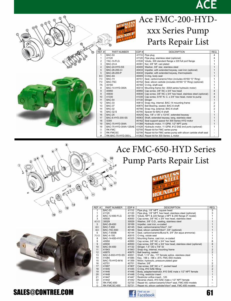
ACE
Ace FMC-650-HYD Series Pump Parts Repair List
Ace Pump Corporation P.O. Box 13187 Memphis, TN 38113www.AcePumps.com Phone: 901-948-8514 Fax: 901-774-6147
FMC-650F-HYD
Ace Form # FMC-650F-HYDRevised 01/10
REF. # PART NUMBER EDP # DESCRIPTION REQ.1 BAC-53 41110 Pipe plug, 1/8” NPT, square head 31 41120 41120 Pipe plug, 1/8” NPT, hex head, stainless steel (optional) 32 BAC-12-650-FLG 30159 Volute, NPT & 220 flange x NPT & 200 flange (F model) 13 40930 40930 Cap screw, 3/8” NC x 3/4” hex head, stainless steel 1
4jk 30029 30029 Washer, 3/8” O.D., sealing, stainless steel 15 BAC-26-650 30169 Impeller, cast iron, e-coated 1
6j BAC-7-650 40145 Seal, carbon/ceramic/Viton®, 3/4” 16k BAC-7SC-650 40146 Seal, silicon carbide/Viton®, 3/4” (optional) 16 BAC-7-650B 40144 Seal, carbon/ceramic/Buna N, 3/4” (for aqua ammonia) 1
7jk BAC-4-150 40015 O-ring, volute seal 18 BAC-14-650-HYD 40325 Mounting frame, cast iron, e-coated 19 40950 40950 Cap screw, 3/8” NC x 3/4” hex head 89 40930 40930 Cap screw, 3/8” NC x 3/4” hex head, stainless steel (optional) 8
10 BAC-54-650 41132 Slinger, 1.5” OD x 7/8” ID 111 41943 41943 Snap ring, internal, mounting frame 212 40875 40875 Ball bearing, sealed 213 BAC-6-650-HYD-SS 40051 Shaft, 1.13” dia., 11T female spline, stainless steel 114 41085 41085 Key, .188 x .188 x .875, FMC-650 models 115 BAC-75-HYD-M16 41359 Motor, hydraulic, pressure plated gear 116 42701 42701 Washer, 3/8” 217 41907 41907 Cap screw, 3/8” NC x 1”, socket head 218 41445 41445 O-ring, #10 SAE fitting 219 41446 41446 Body, adapter/restrictor, #10 SAE male x 1/2” NPT female 120 41448 41448 O-ring, restrictor insert 121 41447 41447 Restrictor orifice insert, .125 122 41442 41442 Reverse check, #10 SAE male x 1/2” NPT female 1j RK-FMC-650 52720 Repair kit, carbon/ceramic/Viton® seal, FMC-650 models --k RK-FMCSC-650 52721 Repair kit, silicon carbide/Viton® seal, FMC-650 models --
Viton® is a registered trademark of DuPont Dow Elastomers.
Ace Pump Corporation P.O. Box 13187 - 1650 Channel Avenue Memphis, TN 38113www.AcePumps.com Phone: 901-948-8514 Fax: 901-774-6147
Ace Form # FMC-200F-HYD-304Revised 08/08
FMC-200F-HYD-304
34
56
78
910
19
1
7A 11
2
1312
14 15
14 13
12
17
18
16
REF. # PART NUMBER EDP # DESCRIPTION REQ.1 BAC-53 41110 Pipe plug 41 41120 41120 Pipe plug, stainless steel (optional) 42 7AC-14-FLG 41530 Volute, 300 standard flange x 220 full port flange 13 BAC-23-A 40391 Nut, 3/8” NF, cad plated 14 BAC-24-HYD-SS 40400 Washer, 3/8” star, stainless steel 15 BAC-26-200-CI 40433 Impeller, with extended keyway, cast iron (optional) 15 BAC-26-200-P 40434 Impeller, with extended keyway, thermoplastic 1
6 BAC-4A 40005 O-ring, body seal 17 BAC-7V 40151 Seal, carbon/ceramic/Viton (includes 40160 “O” Ring) 17 BAC-7SC 40152 Seal, silicon carbide (includes 40160 “O” Ring) (optional) 17A 40160 40160 O-ring, shaft seal 18 BAC-14-HYD-300A 40314 Mounting frame (for -300A series hydraulic motor) 19 40950 40950 Cap screw, 3/8” NC x 3/4” hex head 49 40930 40930 Cap screw, 3/8” NC x 3/4” hex head, stainless steel (optional) 410 41330 41330 Cap screw, 5/16” N. C. x 3/4” hex head, motor to pump 411 BAC-54 41130 Slinger 112 BAC-33 40810 Snap ring, internal, BAC-14 mounting frame 213 BAC-37 40870 Ball Bearing, sealed, BAC-6 shaft 214 BAC-32 40790 Snap ring, external, BAC-6 shaft 215 BAC-32-S 40795 Spacer for BAC-6 shaft 116 BAC-25 40425 Key, 1/8” x 1/8” x 13/16”, extended keyway 117 BAC-6-HYD-200-SS 40063 Shaft, extended keyway, tang, stainless steel 118 S300 40162 Seal support spacer for 300 Series HYD motor 119 BAC-75-HYD-304A 41388 Hydraulic motor, 11 GPM, 1/2" NPT ports 119 BAC-75-HYD-304A-12SAE 41426 Hydraulic motor, 11 GPM, #12 SAE end ports (optional) 1 RK-FMC 52700 Repair kit for FMC series pump - RK-FMCSC 52706 Repair kit for FMC series pump with silicon carbide shaft seal -# RK-BAC-75-HYD-300-L 41362 Repair kit for 300 Series -L motor -
Ace FMC-200-HYD-xxx Series Pump Parts Repair List

ACE
62 800-433-3579
Ace FMC-850-HYD Series Pump Parts Repair List
Ace Pump Corporation P.O. Box 13187 Memphis, TN 38113www.AcePumps.com Phone: 901-948-8514 Fax: 901-774-6147
FMC-750F-HYD
Ace Form # FMC-750F-HYDRevised 01/10
REF. # PART NUMBER EDP # DESCRIPTION REQ.1 BAC-53 41110 Pipe plug, 1/8” NPT 42 BAC-12-750-FLG 30158 Volute, 300 X 220 flange, cast iron, e-coated 13 40397 40397 Acorn nut, 5/8”-11 stainless steel 1
4j ACAL-4 30009 O-ring, volute seal 25 BAC-26-750-CI 30182 Impeller, cast iron, e-coated 16 BAC-16-750 45264 Seal plate, cast iron, e-coated 17 41107 41107 Plug, #8 SAE X 1/4” FNPT, hex, with o-ring 18 41316 41316 Air valve, 1/4” NPT 1
9j BAC-7-750V 40147 Dual seal assembly, Type 21, .875 shaft 110 41108 41108 Plug, #8 SAE, hex head, with o-ring 111 44038 44038 Bushing, 1/2” MNPT x 1/8” FNPT 112 50150 50150 Pressure gauge, 0-60 PSI, 1/8” NPT 113 55850 55850 Site gauge, brass 1/2” NPT 114 45267 45267 Spacer, seal plate 415 42701 42701 Washer, 3/8”, motor mount (2) & volute (1-behind discharge) 316 BAC-14-750-HYD 40333 Mounting frame, cast iron, e-coated 117 40952 40952 Cap screw, 3/8” NC x 2-1/2”, hex head (volute) 418 41907 41907 Cap screw, 3/8” NC x 1”, socket head (seal plate, motor mount) 419 BAC-54-650 41132 Slinger, 7/8” shaft 120 41943 41943 Snap ring, internal, frame 221 ACAL-32 30174 Snap ring, external, shaft 222 40875 40875 Ball bearing, sealed 223 41085 41085 Key, .188 x .188 x .875 124 BAC-6-750-HYD-SS-WS 40066 Shaft, 11T female spline, stainless steel 125 BAC-32-750 40793 Spacer, shaft 126 BAC-75-HYD-M22 41355 Hydraulic motor, pressure plated gear type, 18 GPM 126 BAC-75-HYD-M25 41356 Hydraulic motor, pressure plated gear type, 20 GPM 1
* 27j 55032 55032 Barrier fluid, quart 1.32j RK-FMC-750 52724 Repair kit, includes items 4 (2 pcs.), 9, and 27 (2 qts.) --
* - not shown in parts diagram
14
56 7
8
23
4
1011 12
1413
15 16 17 18
19 20 2122
23
2421
2522 20
2615 18
9
Ace FMC-750-HYD Series Pump Parts Repair List
Ace Pump Corporation P.O. Box 13187 Memphis, TN 38113www.AcePumps.com Phone: 901-948-8514 Fax: 901-774-6147
FMC-850F-HYD
REF. # PART NUMBER EDP # DESCRIPTION REQ.1 20750 20750 Pipe plug, 1/4” NPT, volute & seal reservoir fill/drain 62 BAC-12-850 30164 Volute, 300 X 300 flange, cast iron, e-coated 1
3j 40018 40018 O-ring, volute seal 24 40397 40397 Nut, acorn, 5/8”-11 15 BAC-26-850-CI 30184 Impeller, cast iron, e-coated 16 BAC-16-850 45265 Seal plate, cast iron, e-coated 1
7j BAC-7-850V 40148 Dual seal assembly, Type 21, 1.25” shaft 18 BAC-14-850-HYD 40318 Mounting frame, cast iron, e-coated 19 40950 40950 Cap screw, 3/8” NC x 3/4” hex head 810 55850 55850 Sight gauge, brass, 1/2” NPT 111 GE-54 42220 Slinger 112 41945 41945 Snap ring, external, for BAC-6-850-HYD-SS shaft 413 40876 40876 Ball bearing, front, for BAC-6-850-HYD-SS shaft 114 BAC-50 41080 Key, 3/16” x 3/16” x 1-1/4”, impeller 115 BAC-6-850-HYD-SS 40065 Shaft, female 11T spline, stainless steel 116 40877 40877 Ball bearing, rear, for BAC-6-850-HYD-SS shaft 117 BAC-75-HYD-M30 41357 Hydraulic motor, pressure plated gear type, 23 GPM, case drain 118 42701 42701 Washer, 3/8” 219 41907 41907 Cap screw, 3/8” NC x 1” socket head 2
20j 55032 55032 Barrier fluid, quart 0.75j RK-FMC-850 52725 Repair kit, includes items 3(2 pcs.), 7, and 20 (1 quart) -
Ace Form # FMC-850F-HYDRevised 01/10

ACE
GE-650 Features• Impeller attaches directly to 5/8” (1.59 cm) NF threaded shaft on 5.5 HP (4.1 KW) engine• Stainless steel shaft sleeve with O-ring leak protection• All iron construction• Available complete or less engine
GE-660 Features• Impeller attaches directly to 3/4” (1. 91 cm) keyed shaft on 5.5 HP (4.1 KW) engine• Stainless steel shaft sleeve with O-ring leak protection• All iron construction• Available complete or less engine
MAXIMUM PRESSURE: 120 PSI (8.3 BAR) MAXIMUM FLOW: 110 GPM (416 LPM)
ACE Gas Driven Centrifugal Pump
Call or E-mail us for more informa-tion and pricing on any of the pumps
you see here.
We have a large in stock inventory!
We order direct from the manufactur-er for pumps and parts which means
great prices and quality parts.
Our sales team can help with your custom orders too!
REF #
PART NUMBER DESCRIPTION REQ.
1 BAC-53 Pipe plug, 1/8” NPT 31 41120 Pipe plug, 1/8” NPT, stainless steel (optional) 32 ACAL-12 Volute, 1 1/2” x 1 1/4”, clockwise rotation 13 ACAL-28 Impeller, cast iron, right hand thread 1*4 GE-8-V-A O Ring for GE-6-A-SS shaft sleeve 15 GE-6-SS-A Sleeve for 1” O.D. shaft, stainless steel 1*6 GE-7-V Seal, 1” Type 6 mechanical seal, Viton 1*7 BAC-4-150 O Ring, volute seal 18 ACAL-55 Bracket 19 40950 Cap screw, 3/8” NC x 3/4” hex head 89 40930 Cap screw, 3/8”NC x 3/4”, stainless steel (optional) 8
10 GE-54 Slinger 111 GE-60 Cap screw, 5/16” NF x 3/4” 411 GE-60-SS Cap screw, 5/16” NF x 3/4”, stainless steel (optional) 4** 42068 Engine, 5.5 HP Honda (GX160K1TX2) 1** 42069 Engine, 5.5 HP Briggs & Stratton (110432-0035-E1) 1** RK-GE-650 Repair kit 1

BANJO
64 800-433-3579
1½" & 2" Poly Self Priming Pump With Gas Engine1½” Model Number Inlet/ Outlet Size Powertrain Start Type HP
RatingPump Type
Max GPM
GPM @ 10 PSI
GPM @ 20 PSI
Max PSI
Est. Ship Wt
150P-3 NPT 1½” x 1½” Briggs & Stratton Pull 3.5 Poly 125 95 70 35 40 lbs
2” Model Number Inlet/ Outlet Size Engine Make Start Type HP Rating
Pump Type
Max GPM
GPM @ 10 PSI
GPM @ 20 PSI
Max PSI
Est. Ship Wt
200P-3 NPT 2” x 2” Briggs & Stratton Pull 3.5 Poly 140 105 70 40 40 lbs200PH-5 NPT 2” x 2” Honda Pull 5.5 Poly 195 170 145 45 50 lbs200PH-5E NPT 2” x 2” Honda Elec/ Pull 5.5 Poly 195 170 145 45 50 lbs200PH6 NPT 2” x 2” Honda Pull 6.5 Poly 195 170 145 45 53 lbs200P6PRO NPT 2” x 2” Briggs & Stratton Pull 6.5 Poly 195 170 145 45 50 lbs
1½" & 2" Poly Pumps- Self Priming Pump Only
(For Gas Engines)With Pedestal Bearing (For Electric Motors)
1½” Model Number Description Seal Type Pedestal
Bearing
150PO 1½” Poly Pump, 3 Vane Impeller (Requires ¾ Motor Shaft) Standard NO150PO-V 1½” Poly Pump, 3 Vane Impeller (Requires ¾ Motor Shaft) FKM (Viton type) with 316 SS Seal NO
150PB 1½” Poly Bearing Pedestal, ¾” Shaft & 3 Vane Impeller Standard YES150PB-V 1½” Poly Bearing Pedestal, ¾” Shaft & 3 Vane Impeller FKM (Viton type) with 316 SS Seal YES
2” Model Number Description Seal Type Pedestal
Bearing
200PO 2” Poly Pump, 3 Vane Impeller (Requires ¾ Motor Shaft) Standard NO205PO 2” Poly Pump, 5 Vane Impeller (Requires ¾ Motor Shaft) Standard NO
200PO-V 2” Poly Pump, 3 Vane Impeller (Requires ¾ Motor Shaft) FKM (Viton type) with 316 SS Seal NO205PO-V 2” Poly Pump, 5 Vane Impeller (Requires ¾ Motor Shaft) FKM (Viton type) with 316 SS Seal NO
200PB 2” Poly Bearing Pedestal, ¾” Shaft & 3 Vane Impeller Standard YES205PB 2” Poly Bearing Pedestal, ¾” Shaft & 5 Vane Impeller Standard YES
200PB-V 2” Poly Bearing Pedestal, ¾” Shaft & 3 Vane Impeller FKM (Viton type) with 316 SS Seal YES205PB-V 2” Poly Bearing Pedestal, ¾” Shaft & 5 Vane Impeller FKM (Viton type) with 316 SS Seal YES
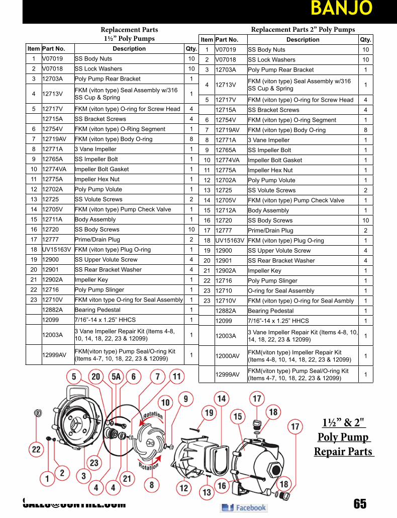
BANJO
Replacement Parts 1½” Poly Pumps
Item Part No. Description Qty.1 V07019 SS Body Nuts 102 V07018 SS Lock Washers 103 12703A Poly Pump Rear Bracket 1
4 12713V FKM (viton type) Seal Assembly w/316 SS Cup & Spring 1
5 12717V FKM (viton type) O-ring for Screw Head 412715A SS Bracket Screws 4
6 12754V FKM (viton type) O-Ring Segment 17 12719AV FKM (viton type) Body O-ring 88 12771A 3 Vane Impeller 19 12765A SS Impeller Bolt 110 12774VA Impeller Bolt Gasket 111 12775A Impeller Hex Nut 112 12702A Poly Pump Volute 113 12725 SS Volute Screws 214 12705V FKM (viton type) Pump Check Valve 115 12711A Body Assembly 116 12720 SS Body Screws 1017 12777 Prime/Drain Plug 218 UV15163V FKM (viton type) Plug O-ring 119 12900 SS Upper Volute Screw 420 12901 SS Rear Bracket Washer 421 12902A Impeller Key 122 12716 Poly Pump Slinger 123 12710V FKM viton type O-ring for Seal Assembly 1
12882A Bearing Pedestal 112099 7/16”-14 x 1.25” HHCS 1
12003A 3 Vane Impeller Repair Kit (Items 4-8, 10, 14, 18, 22, 23 & 12099) 1
12999AV FKM(viton type) Pump Seal/O-ring Kit (Items 4-7, 10, 18, 22, 23 & 12099) 1
Replacement Parts 2” Poly PumpsItem Part No. Description Qty.
1 V07019 SS Body Nuts 102 V07018 SS Lock Washers 103 12703A Poly Pump Rear Bracket 1
4 12713V FKM (viton type) Seal Assembly w/316 SS Cup & Spring 1
5 12717V FKM (viton type) O-ring for Screw Head 412715A SS Bracket Screws 4
6 12754V FKM (viton type) O-ring Segment 17 12719AV FKM (viton type) Body O-ring 88 12771A 3 Vane Impeller 19 12765A SS Impeller Bolt 110 12774VA Impeller Bolt Gasket 111 12775A Impeller Hex Nut 112 12702A Poly Pump Volute 113 12725 SS Volute Screws 214 12705V FKM (viton type) Pump Check Valve 115 12712A Body Assembly 116 12720 SS Body Screws 1017 12777 Prime/Drain Plug 218 UV15163V FKM (viton type) Plug O-ring 119 12900 SS Upper Volute Screw 420 12901 SS Rear Bracket Washer 421 12902A Impeller Key 122 12716 Poly Pump Slinger 123 12710 O-ring for Seal Assembly 123 12710V FKM (viton type) O-ring for Seal Asmbly 1
12882A Bearing Pedestal 112099 7/16”-14 x 1.25” HHCS 1
12003A 3 Vane Impeller Repair Kit (Items 4-8, 10, 14, 18, 22, 23 & 12099) 1
12000AV FKM(viton type) Impeller Repair Kit (Items 4-8, 10, 14, 18, 22, 23 & 12099) 1
12999AV FKM(viton type) Pump Seal/O-ring Kit (Items 4-7, 10, 18, 22, 23 & 12099) 1
1½” & 2" Poly Pump
Repair Parts

BANJO
66 800-433-3579
Model Number Inlet/ Outlet Size Powertrain Start Type HP
RatingPump Type
Max GPM
GPM @ 10 PSI
GPM @ 20 PSI
Max PSI
Est. Ship Wt
222PIH5 NPT 2” x 2” Honda Pull 5.5 Cast 205 175 134 43 103 lbs222PIH5E NPT 2” x 2” Honda Pull 5.5 Cast 205 175 134 43 110 lbs222PIH6 NPT 2” x 2” Honda Pull 6.5 Cast 205 175 134 43 110 lbs222PI6PRO NPT 2” x 2” Briggs & Stratton Pull 6.5 Cast 205 175 134 43 107 lbs
2” Cast Iron 222 Series Self Priming Pump
Model Number Description Seal Type Pedestal Bearing222PBI 2” Cast Iron Pump, ¾” Shaft Straight Keyway Standard YES222POI 2” Cast Iron Pump Only, FULL Impeller Standard NO
225POI** 2” Cast Iron Pump Only, TRIMMED Impeller Standard NO
2” Cast Iron 222 Series Self Priming PumpPump Only (For Gas Engines)
With Pedestal Bearing (For Electric Motors)
Model Number Description HP Rating Min GPM
RequiredMax GPM Required Min PSI Max PSI Est. Ship
Wt
HSV1000 Hydraulic Motor Spool Valve N/A 6 GPM 10 GPM 600 3000 11 lbsHY1013 Only Gresen MGG2 Hyd Motor (No Pump) 12 6 @ 2400 rpm 10 @ 4000 rpm 200 2000 4.5 lbs
Model Number Description HP Rating
Max GPM
GPM @ 10 PSI
GPM @ 20 PSI
Max PSI
Est. Ship Wt
222PIHY 2” Cast Pump w/ Gresen MGG2 Hyd Motor 12 205 175 134 44 110 lbs
2” Cast Iron 222 Series Hydraulic Drive Pumps
Repair Parts

BANJO
2” Cast Iron 222 Series Pedestal Pump Repair Parts
Item Part No. Description Qty. Item Part No. Description Qty.1 12882A Bearing Pedestal Assembly 1 19 12717 O-ring 4
12600B Hydraulic Pedestal Assembly 1 20 12713V Seal Assembly 1
2 17010 ½” Jam Nut 1 20 12713SD Severe Duty Seal 13 15022 Handle 1 21 15712 Body 14 12765A 5/16” - 24 x 1.12 Impeller Bolt 1 22 17013 Flange Gasket 25 13778 O-ring 2 23 17000 Threaded Flange 26 13777 Prime/Drain Plug 2 24 17019 5/16” - 18 x 0.75 HHCS 87 V10118 5/16” Lock Washer 9 25 V10118 5/16” Lock Washer 88 15772 5 Vane Impeller 1 ** 12099 7/16”-14 x 1.25” HHCS 19 12716 Pump Slinger 1 ** 15751 Bracket Shim 1
10 12715A 5/16” - 24 x 1.75 HHCS 13 ** 15752 Impeller Shim 1
11 12774VA Impeller Bolt Gasket 1 ** 17033 Z-Rails
12 12719A Body O-ring 1 ** 17034 5/16” - 18 x 1¾” Zinc Plated 413 12705 Check Valve 1 ** V10119 5/16” -18 Hex Nut 414 15702 Volute 1 ** V10118 5/16” Lock Washer 4
15 15703 Rear Bracket 1 ** 15000 Repair Kit(Items 5, 8, 11-13, 18-20, 12099, 15751 & 15752)
16 12902A 3/16” sq. x 5/8” Key 1 ** 15000V FKM (Viton type) Repair Kit 117 12901 5/16” Flat Washer 4 ** 15999 Seal Kit (Items 5, 11-13, 18-20, 12099, 15751 & 15752) 118 12710 O-ring 1 ** 15999V FKM (Viton type) Seal Kit 1

BANJO
68 800-433-3579
2” & 3” Cast Iron 222 & 333 Series Self Priming Electric Motor Driven Pump
Model Number Inlet/ Outlet Size Description HP
RatingPump Type
Max GPM
GPM @ 10 PSI
GPM @ 20 PSI
Max PSI
Est. Ship Wt
222PIE5 2” x 2” 3-Phase Electric Motor w/ EPDM Elastomers 5 Cast 205 175 134 44 180 lbs222PIE51 2” x 2” 1-Phase Electric Motor w/ EPDM Elastomers 5 Cast 205 175 134 44 190 lbs333PIE15 3” x 3” 3-Phase Electric Motor w/ EPDM Elastomers 15 Cast 430 387 280 36 242 lbs
21
23 20 26
24 2223 20
13
2
1
17
1525
16
18
147
9
312
11 6
8
10
19
4
5
6 8
Item Part No. Description Qty.1 17010 ½” Jam Nut 1
2 15022 Handle 1
6 12765A 5/16” - 24 x 1.12 Impeller Bolt 1
4 13778 O-ring 2
5 13777 Prime/Drain Plug 2
6 V10118 5/16” Lock Washer 9
7 15772 5 Vane Impeller 1
8 12715A 5/16” - 24 x 1.75 HHCS 13
9 12774VA Impeller Bolt Gasket 1
10 12719A Body O-ring 1 Item Part No. Description Qty.11 12705 Check Valve 1 19 15712 Body 1
12 15702 Volute 1 20 17704 3/16” - 16 x 1.25 HHCS Bolt 8
13 15703 Rear Bracket 1 21 17701 C-Faced Base Plate 1
14 12902A 3/16” SQ. x 5/8” Key 1 22 12046 56C Adapter 1
15 12901 5/16” Flat Washer 4 23 V20018 3/8” Lock Washer 8
16 12710 O-ring 1 24 V20019 3/8” 16 SS Hex Nut 4
17 12717 O-ring 4 25 BF107 5/16” - 18 x 2¼” HHCS Bolt 418 12713V Seal Assembly 1 26 BEM5-182CZ 5HP 3450RPM 3-Phase Motor 1
12713SD Severe Duty Seal 1 ** 15000 Repair Kit (Items 4, 7, 9-11, 14, 16-18, 12099, 15751, 15752) 1
** 12099 7/16”-14 x 1.25 HHCS 1 ** 15000V FKM (viton type) Repair Kit (Items 4, 7, 9-11, 14, 16-18, 12099, 15751, 15752) 1
** 15751 Bracket Shim 1 ** 15999 Seal Kit (Items 4, 9-11, 14, 16-18, 12099, 15751, 15752) 1
** 15752 Impeller Shim 1 ** 1599V FKM (viton type) Seal Kit (Items 4, 9-11, 14, 16-18, 12099, 15751, 15752) 1
2” & 3” Cast Iron 222 & 333 Series Electric Motor
Driven Pump Repair Parts

BANJO
Model Number DescriptionM17000 2” Manifold Outlet FlangeM17002 2” Manifold Inlet Flange
1½” & 2” Cast Iron Self Priming:
Replacement Manifold FlangesPedestal Bearing PumpsPump Only (No Motor)
1½” & 2” Cast Iron Pump Replacement Parts
Model Number Description Shaft Impeller Est Ship Wt
150POI 1½” Cast Iron Pump ¾” Sleeve Standard 47 lbs150PBI 1½” Cast Iron Pump w/ Pedestal Bearing, Straight Keyed ¾” Solid Standard 52 lbs200POI 2” Cast Iron Pump ¾” Sleeve Standard 53 lbs200PBI 2” Cast Iron Pump w/ Pedestal Bearing, Straight Keyed ¾” Solid Standard 56 lbs
150POICF5/8 1½” CI C-Flange Pump 5/8” Sleeve Standard 47 lbs150POICF5/8-4.1 1½” CI C-Flange Pump 5/8” Sleeve 4.1 47 lbs150POICF5/8-4.6 1½” CI C-Flange Pump 5/8” Sleeve 4.6 47 lbs
150POICF7/8 1½” CI C-Flange Pump 7/8” Sleeve Standard 47 lbs150POICF7/8-4.1 1½” CI C-Flange Pump 7/8” Sleeve 4.1 47 lbs150POICF7/8-4.6 1½” CI C-Flange Pump 7/8” Sleeve 4.6 47 lbs
200POICF5/8 2” CI C-Flange Pump 5/8” Sleeve Standard 47 lbs200POICF5/8-4.1 2” CI C-Flange Pump 5/8” Sleeve 4.1 47 lbs200POICF5/8-4.6 2” CI C-Flange Pump 5/8” Sleeve 4.6 47 lbs
200POICF7/8 2” CI C-Flange Pump 7/8” Sleeve Standard 47 lbs200POICF7/8-4.1 2” CI C-Flange Pump 7/8” Sleeve 4.1 47 lbs200POICF7/8-4.6 2” CI C-Flange Pump 7/8” Sleeve 4.6 47 lbs

BANJO
70 800-433-3579
Item Part No. Description Qty.1 17001 Threaded Outlet Flange 12 17003 Threaded Inlet Flange 13 17004 Adapter for Gas Engine 13 17046 C-Flange Adapter 14 17005 5/8” Sleeve Drive for Electric Motor 14 17006 ¾” Sleeve Drive 14 17007 7/8” Sleeve Drive for Electric Motor 15 17008* 5” Impeller 15 17008-4.6 4.6” Trimmed Impeller 15 17008-4.1 4.1” Trimmed Impeller 16 17010 ½” Hex Nut 17 17011 Wear Plate 18 17013 EPDM Gasket 19 17016 Check Valve Assembly 110 17018 Gasket Adapter 111 15022 Handle 112 17023 5/8” Clamp for ¾” Shaft Assembly (Old Style) 112 17123 5/8” Clamp for ¾” Shaft Assembly (Keyed) 112 17024 7/8” Clamp for Shaft Assembly 113 17026 Pump Housing 114 V10118 5/16” Lock Washer 1815 V10119 5/16” - 18 SS Hex Nut 616 12882A Complete Pedestal Assembly 117 17040 5/16” -24 x 1.00” Cap Screw 418 17028 EPDM Seal Assembly 118 17035* FKM (viton type) Seal Assembly 118 17035SD Severe Duty Seal 119 17042 Stud 620 17019 5/16”-18 x ¾” Cap Screw 821 17009B 5/8” Impeller Nut 122 17130 C Sink Flat Head Screw 223 12777 Plug 124 UV15163 O-ring 1** 12882R Housing 1** 12883R Bearing Pedestal w/ ¾” Shaft Only 1** 12884 Internal Retaining Clip for Pedestal 1** 12883B Bearings 2** 17033 Z Rails (Pair) 1** 17100 Repair Kit (Consists of items 4*, 5*, 7,10,18*) 1
Item Part No. Description Qty.1 17000 Threaded Outlet Flange 11 M17000 2” Manifold Outlet Flange 12 17002 Threaded Inlet Flange 12 M17002 2” Manifold Inlet Flange 13 17004 Adapter for Gas Engine 13 17046 C-Flange Adapter 14 17005 5/8” Sleeve Drive for Electric Motor 14 17006 ¾” Sleeve Drive 14 17007 7/8” Sleeve Drive for Electric Motor 15 17008* 5” Impeller 15 17008-4.6 4.6” Trimmed Impeller 15 17008-4.1 4.1” Trimmed Impeller 16 17010 ½” Hex Nut 17 17011 Wear Plate 18 17013 EPDM Gasket 19 17016 Check Valve Assembly 1
10 17018 Gasket Adapter 111 15022 Handle 112 17023 5/8” Clamp for ¾” Shaft Assembly (Old Style) 112 17123 5/8” Clamp for ¾” Shaft Assembly (Keyed) 112 17024 7/8” Clamp for Shaft Assembly 113 17026 Pump Housing 114 V10118 5/16” Lock Washer 1815 V10119 5/16” - 18 SS Hex Nut 6
12882R Housing 1
12883R Bearing Pedestal w/ ¾” Shaft Only 1
12884 Internal Retaining Clip for Pedestal 1
12883B Bearings 2
16 12882A Complete Pedestal Assembly 117 17040 5/16” -24 x 1.00” Cap Screw 418 17028 EPDM Seal Assembly 118 17035* FKM (viton type) Seal Assembly 118 17035SD Severe Duty Seal 119 17042 Stud 620 17019 5/16”-18 x ¾” Cap Screw 821 17009B 5/8” Impeller Nut 122 17130 C Sink Flat Head Screw 223 12777 Plug 124 UV15163 O-ring 1
17033 Z Rails (Pair) 1
17100 Repair Kit (Consists of items 4*, 5*, 7,10,18*) 1
1½” CI Pump Replacement Parts 2” CI Pump Replacement Parts

BANJO
3” Cast Iron Gas Driven Replacement Parts
Item Part No. Description Qty.Item Part No. Description Qty. 14 18029 Clamp Assembly (Old Style) 1
1 18008 NPT Outlet Flange 1 18129 Clamp Assembly (New Style) 1
M18008 3” Manifold Outlet Flange 1 15 18001 Pump Housing 1
2 18012 NPT Inlet Flange 1 16 18030 3/8” -24 x 2¼” Bolt 2
M18012 3” Manifold Inlet Flange 1 17 18106 Wear Plate Flat Head Screw 2
3 18026 Adapter for Gas Engine & Bearing Ped 1 18 V20018 3/8” Lock Washer 8
18048 C-Flange Adapter 1 19 18032 3/8” x 24 SS Hex Nut 2
18049 Hydraulic Motor Adapter 1 20 18504 1” Shaft 1
18055 Hydraulic Adapter Shaft 1 21 18500 Bearing Pedestal 1
4 13777 Plug 1 18502 Bearing SKF 66306-2RS1/C3 2
5 18023 1” Impeller & Drive Shaft for Gas Engine 1 22 17704 Bolt 418023-1.125 1-1/8” Impeller & Drive Shaft for Electric Motors 1 23 18025 FKM (viton type) Seal Assembly 1
6 12777 Plug 1 18025SD Severe Duty Seal 1
7 18034 5/8” SS Jam Nut 1 24 V20019 3/8” 16 SS Hex Nut 68 18004 Wear Plate 1 25 V20018 3/8” SS Lock Washer 69 18009 EPDM Outlet Gasket 1 26 18218 3/8” -16 x 3/8” -24 x 1½” SS Stud 6
10 18013 Gasket Check Valve Assembly 1 27 13778 O-ring 111 18021 Adapter Gasket 1 28 UV15163 O-ring 112 18010SS 3/8” - 16 x 11/8” SS Cap Screw HXHD 8 ** 18035 Z-Rail Mounting Bracket (Pair) 113 18033 Handle 1 ** 18100 Repair Kit (Consist of items 5, 8,11,17, 23, & 18005) 1
Model Number DescriptionM18008 3” Manifold Outlet FlangeM18012 3” Manifold Inlet Flange
3” Cast Iron Self Priming Gas Driven PumpModel Number Inlet/ Outlet Size Powertrain Start Type HP
RatingPump Type
Max GPM
GPM @ 10 PSI
GPM @ 20 PSI
Max PSI
Est. Ship Wt
300PIH-8 NPT 3” X 3” Honda Elec/Pull 8 Cast 340 272 219 50 195 lbs300PI11PERO NPT 3” X 3” Briggs & Stratton Elec/Pull 11 Cast 340 272 219 50 170 lbs
300PIH-11 NPT 3” X 3” Honda Elec/Pull 11 Cast 340 272 219 50 192 lbs300PIH13 NPT 3” X 3” Honda Elec/Pull 13 Cast 340 272 219 50 210 lbs
Model Number Description Shaft Est Ship
Wt300POI 3” Cast Iron Pump (For Gas Engine Mounting) For 1” Shaft 90 lbs
300POICF 3” Cast iron C-Flange Pump 1-1/8” Sleeve 106 lbs300PBI 3” Cast Iron Bearing Pedestal Pump 1” Solid Keyed 125 lbs

BANJO
72 800-433-3579
Model Number Inlet/ Outlet Size Powertrain Start Type HP Rating
Pump Type
Max GPM
GPM @ 10 PSI
GPM @ 20 PSI
Max PSI
Est. Ship Wt
201PIH5W NPT 2” X 2” Honda Pull 5.5 Cast 190 147 114 45 208 lbs201PI6PROW NPT 2” X 2” Briggs & Stratton Pull 6.5 Cast 190 147 114 45 198 lbs301PIH13W NPT 3” X 3” Honda Elec/Pull 13 Cast 350 300 280 63 240 lbs
Model Number Description Shaft Est. Ship Wt
201PBIW 2” Cast Iron Pump (For Gas Engine Mounting) For 1” Shaft 64 lbs201POIW 2” Cast Iron C-Flange Pump (For Electric Motor Mount) ¾” Keyed Shaft 59 lbs301PBIW 3” Cast Iron Pump (For Gas Engine Mounting) For 1” Shaft 135 lbs301POIW 3” Cast iron C-Flange Pump (For Electric Motor Mount) ¾” Keyed Shaft 130 lbs
2” & 3” Cast Iron Wet Seal Self Priming Gas Driven Pump
2” Cast Iron Gas Driven Pump Replacement Parts
Item Part No. Description Qty. Item Part No. Description Qty.1 V10118 5/16” Lock Washer 6 16 17000 Outlet Flange 1
2 V10119 5/16” -18 Hex Nut 6 17 17013 EPDM Outlet Gasket 13 15022 Handle 1 18 17242 Housing Stud 64 17010 ½” Hex Nut 1 19 17208 Impeller 15 17018 Gasket Adapter 1 20 17032 Pipe Plug 16 17123 5/8” Clamp, ¾” Shaft Asmb Keyed 1 21 17019 5/16”-18 x ¾” Cap Screw 47 17226 Pump Housing 1 22 V10118 5/16” Lock Washer 48 17200A Wet Seal Assembly 1 23 12777 Fill Plug 29 12882A Bearing Pedestal 1 24 17202 Cover Plate 110 17019 5/16”-18 x ¾” HHCS 4 25 17018 Gasket Adapter 111 V10118 5/16” Lock Washer 4 26 17201A Reservoir 112 17002 Inlet Flange 1 27 17235 FKM (viton type) Mechanical Seal Asmb 113 17016 EPDM Check Valve Gasket Asmb 1 28 17009B 5/8” Impeller Nut 114 17019 5/16” -18 x ¾” HHCS 4 29 17206A Adapter Shaft 115 V10118 5/16” Lock Washer 4 30 UV15163 O-ring 2

BANJO
3” Cast Iron Gas Driven Pump Replacement Parts
Item Part No. Description Qty. Item Part No. Description Qty.1 18001 Pump Housing 1 14 18021 Adapter Gasket 1
2 18106 Flat Head Socket Cap Screw 2 15 17704 3/8” -16 x 1¼” HHCS 43 12777 Fill Plug 2 16 18033 Handle 14 18013 Inlet/Check EPDM Gasket 1 17 18034 5/8” -11 Jam Nut 15 18008 NPT Outlet Flange 1 18 18500 Bearing Pedestal 16 18012 NPT Inlet Flange 1 19 18010SS 3/8” - 16 x 11/8” HHCS 87 13777 Plug 2 20 18218 Pump Housing Stud 68 18004 Wear Plate 1 21 18206 Impeller 19 18009 EPDM Outlet Gasket 1 22 18202A Cover Plate 110 V20018 3/8” Lock Washer 18 23 18021 Adapter Gasket 111 V20019 3/8” 16 SS Hex Nut 6 24 15035 Mechanical Seal Assembly 112 18129 Clamp Assembly Keyed 1 25 18203A Wet Seal Reservoir 113 18200A Wet Seal Assembly 1 26 13778 O-ring 2
27 UV15163 O-ring 2
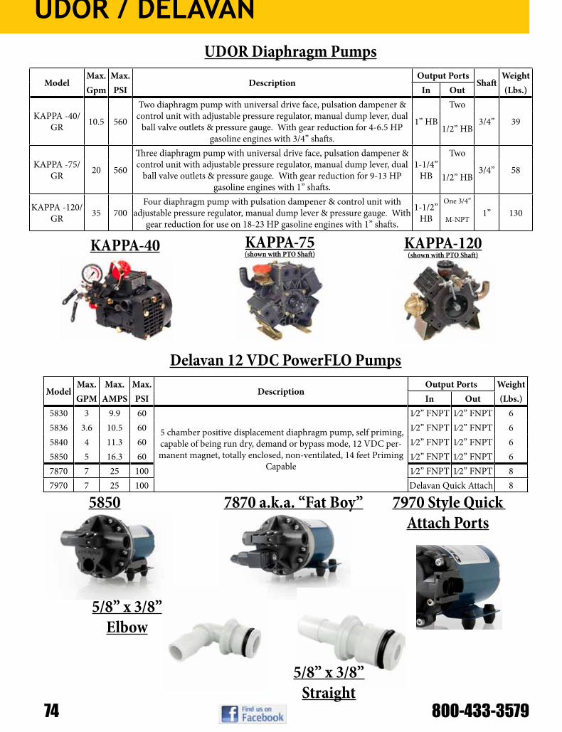
UDOR / DELAVAN
74 800-433-3579
ModelMax. Max.
DescriptionOutput Ports
ShaftWeight
Gpm PSI In Out (Lbs.)
KAPPA -40/GR 10.5 560
Two diaphragm pump with universal drive face, pulsation dampener & control unit with adjustable pressure regulator, manual dump lever, dual
ball valve outlets & pressure gauge. With gear reduction for 4-6.5 HP gasoline engines with 3/4” shafts.
1” HB
Two
3/4” 391/2” HB
KAPPA -75/GR 20 560
Three diaphragm pump with universal drive face, pulsation dampener & control unit with adjustable pressure regulator, manual dump lever, dual
ball valve outlets & pressure gauge. With gear reduction for 9-13 HP gasoline engines with 1” shafts.
1-1/4” HB
Two
3/4” 581/2” HB
KAPPA -120/GR 35 700
Four diaphragm pump with pulsation dampener & control unit with adjustable pressure regulator, manual dump lever & pressure gauge. With
gear reduction for use on 18-23 HP gasoline engines with 1” shafts.
1-1/2” HB
One 3/4”
1” 130M-NPT
UDOR Diaphragm Pumps
KAPPA-40 KAPPA-75(shown with PTO Shaft)
KAPPA-120(shown with PTO Shaft)
ModelMax. Max. Max.
DescriptionOutput Ports Weight
GPM AMPS PSI In Out (Lbs.)5830 3 9.9 60
5 chamber positive displacement diaphragm pump, self priming, capable of being run dry, demand or bypass mode, 12 VDC per-manent magnet, totally enclosed, non-ventilated, 14 feet Priming
Capable
1⁄2” FNPT 1⁄2” FNPT 65836 3.6 10.5 60 1⁄2” FNPT 1⁄2” FNPT 65840 4 11.3 60 1⁄2” FNPT 1⁄2” FNPT 65850 5 16.3 60 1⁄2” FNPT 1⁄2” FNPT 67870 7 25 100 1⁄2” FNPT 1⁄2” FNPT 87970 7 25 100 Delavan Quick Attach 8
Delavan 12 VDC PowerFLO Pumps
5850 7870 a.k.a. “Fat Boy” 7970 Style Quick Attach Ports
5/8” x 3/8” Straight
5/8” x 3/8” Elbow

CDS-JB
Model Number Inlet/ Outlet Size Piston Stroke Rated Speed Rated GPM Rated
PSILegacy
Equivalent
NGP-4055-F Series
1” x 1” (200 x 200 Flange)
Single, Double Acting Variable 450
RPM 10.2 120 LM-1250
NGP-5055-DRF Series
1” x 1” (200 x 200 Flange)
Double, Double Acting Variable 450
RPM 20.4 120 N/A
NGP-5655-ARF Series
1” x 1½” 200 x 220 Flange
Double, Double Acting Variable 450
RPM
31.2 Combined (10.2 Sm. Side +
21 Lg. Side)120 N/A
NGP-6050 Series
1½” x 1½” FPT
Single, Double Acting Variable 450
RPM 21.0 120 LM-2450
NGP-7050 Series
1½” x 1½” FPT
Single, Double Acting Variable 450
RPM 34.2 120 LM-4450
NGP-8050 Series
1½” x 1½” FPT
Double, Double Acting Variable 450
RPM 42.0 120 N/A
NGP-8055-AR Series
1½” x 1½” FPT
Double, Double Acting Variable 450
RPM42 Combined (21 per side) 120 N/A
NGP-9050 Series
1½” x 1½” FPT
Double, Double Acting Variable 450
RPM 68.4 120 LM-4950
CDS-John Blue Cast Iron Metering Piston Pumps NGP-Series
Model Options [-change last number]• NGP-XXX0 Rope Control Clutch• NGP-XXX5 Without Clutch• NGP-XXX8 Electric Clutch Control• NGP-XXX9 Hydraulic Clutch Control
Additional Model Options [-suffix]:-DR** denotes independent dual inlet & outlet-F denotes flanges-K denotes pump less sprocket-R denotes RC40 chain 18 tooth sprocket-S denotes 316 SS wet-end castings-U denotes Viton wet-end o-rings and rod packing** -DR only available on double piston NGP-5055-DRF, NGP-5655-DRF,NGP-8050 and NGP-9050
Additional Kit Modules (modifies existing pumps):-115670 Manual Clutch Add On - NGP Universal-115671 Hydraulic Clutch Add On - NGP Universal-115672 Electric Clutch Add On - NGP Universal-115673 Stainless Wet-End Conversion – NGP-6050 Series-115674 Stainless Wet-End Conversion – NGP-7050 Series-115675 Stainless Wet-End Conversion – NGP-8050 Series***-115676 Stainless Wet-End Conversion – NGP-9050 Series****** -DR pumps may use 2 single piston stainless conversion kits

CDS-JB
76 800-433-3579
© 2013 CDS-John Blue Co. 14
PARTS LISTING – NGP- 405x / 605x / 705x Series NGP-4050 NGP-6050 NGP-7050 NGP-4050 NGP-6050 NGP-7050 ITEM PART DESCRIPTION PART # PART # PART # ITEM PART DESCRIPTION PART # PART # PART #
1 KEY L-1020 L-1020 L-1020 55 STUFFING BOX 116070-01 115790-01 115690-01 2 SPROCKET RC50-18T 112661-01 112661-01 112661-01 -S STAINLESS N/A 115790-01S 115690-01S
-K NO SPROCKET NOT USED NOT USED NOT USED 56 INBOARD CYL. GASK. 116076-01 115710-01 115710-01 -R SPROCKET RC40-18T 113905-01 113905-01 113905-01 -U FUMIGANT N/A 104826-02 104826-02
3 5/16x3/8 SETSCREW 90532 90532 90532 57 STUFF. BOX INSERT 116068-01 L-1031-2 L-1031-2 4 GREASE FITTING H-28 H-28 H-28 -S STAINLESS NOT USED NOT USED NOT USED 5 5/16x3/8 SETSCREW 90532 90532 90532 58 PACKING - SNAP RING 112698-01 L-1042 L-1042 6 SPROCKET SPACER 115625-01 115625-01 115625-01 59 O-RING S-316 S-316 115604-01 7 O-RING S-316 S-316 S-316 -S STAINLESS N/A 104824-01 115612-01 8 THRUST WASHER 115626-01 115626-01 115626-01 -U FUMIGANT N/A 104824-01 115612-01 9 5/16x1 HEX BOLT 90637 90637 90637 60 O-RING S-316 L-3031 A-2848 10 OIL SEAL 115621-01 115621-01 115621-01 -S STAINLESS N/A 114768-01 114870-01 11 COVER PLATE 115723-01 115723-01 115623-01 -U FUMIGANT N/A 114768-01 114870-01 12 BEARING L-3019 L-3019 L-3019 61 DISCHARGE VALVE 116127-91 115707-91 115607-91 13 CONNECTING ROD L-1008-A L-1008-A 113630-01 62 SUCTION VALVE 116126-91 115706-91 115606-91 14 JOURNAL BEARING L-928 L-928 113629-01 63 INBOARD CYLINDER N/A 115701-02 115601-02 15 ROD BUSHING 113588-01 113588-01 113588-01 -F FLANGED 116071-01 115701-02FLG 115601-02FLG
16 ROD PIN 105895-01 105895-01 105895-01 -S STAINLESS N/A 115701-02S 115601-02S 17 ECCENTRIC - OUTER L-1013-A L-1013-A 113633-01 64 3/8 LOCK WASHER 93024 93024 93024 18 ECCENTRIC - INNER L-1015 L-1015 L-3017 -S STAINLESS N/A 93025 93025 19 TRANSFER SLEEVE NOT USED NOT USED NOT USED 65 3/8 HEX NUT 92024 92024 92024 20 PISTON ROD ASM 116078-91 115712-91 105900-91 66 PLUNGER – PACKING 112696-01 L-1045-V L-1045-V 21 ECCENTRIC PIN L-3004 L-3004 L-3004 -B BUNA PACKING N/A L-1045-A L-1045-A 22 WOODRUFF KEY 108093-01 108093-01 A-4333 67 PLUNGER – GASKET 112712-01 L-1098 L-1098 23 CRANKSHAFT 115614-01 115614-01 115614-01 -U FUMIGANT N/A 114769-01 114769-01 24 O-RING L-1022 L-1022 L-1022 68 PLUNGER – WASHER 112695-01 L-1044-A L-1044-A 25 GREASE ZERK 115647-01 115647-01 115647-01 69 PLUNGER 112700-91 103290-91 112816-91 26 SETTING SLEEVE 115718-01 115718-01 115618-01 70 PLUNGER – LOCKNUT 92125 L-1047 L-1047 27 BEARING L-1007-A L-1007-A L-1007-A 71 VALVE COVER 116073-01 115703-01 115603-01 28 GASKET L-1006 L-1006 L-3002 -S STAINLESS N/A 115703-01S 115603-01S 29 VENT PLUG S-350 S-350 S-350 72 NOT USED 30 NAME PLATE 111958-01 111958-01 111958-01 NOT USED 31 DRIVE SCREW A-3557 A-3557 A-3557 73 3/8 X 1-1/2 HEX BOLT 90911 90911 90911 32 OIL PLUG C-431-B C-431-B C-431-B -S STAINLESS N/A 90654 90654 33 FLANGE COVER 115724-01 115724-01 115724-01 74 OUTBOARD CYL. 116072-01 115702-01 115602-01 34 5/16 X 1 HEX BOLT 90637 90637 90637 -S STAINLESS N/A 115702-01S 115602-01S 35 SETTING HUB 115627-01 115627-01 115627-01 75 1/2 HEX BOLT 90704 90704 90705 36 SCREW A-368 A-368 A-368 -S STAINLESS (2 BOLTS) N/A 90693/90687 90693/90687 37 SNAP RING 115791-01 115791-01 115791-01 76 NOT USED 38 3/8 SELF-LOCK NUT A-3097 A-3097 A-3097 NOT USED 39 SETTING POINTER 115628-01 115628-01 115628-01 77 NOT USED 40 SETTING SCALE 115645-01 115645-01 115645-01 NOT USED 41 3/8x2-1/4 CARR.BOLT 115646-01 115646-01 115646-01 NOT USED 42 OIL SEAL 115622-01 115622-01 115622-01 78 NOT USED 43 CRANKCASE 115720-01 115720-01 115620-01 NOT USED 44 CROSSHEAD GASK. 115711-01 115711-01 115611-01 79 SPROCKET KEY 106493-01 106493-01 106493-01 45 1/2 HEX NUT 92029 92029 92029 A RC50-18T SPRKT ASM 106532-01 106532-01 106532-01
-S STAINLESS N/A 92030 92030 -K NO SPROCKET NOT USED NOT USED NOT USED 46 NOT USED -R RC40-18T SPRKT ASM 113907-01 113907-01 113907-01 47 HEX BOLT 90637 90637 90860 B SPRKT. SPACER ASM 115624-91 115624-91 115624-91 48 CROSSHEAD GUIDE 116069-01 115700-01 115600-01 C CONN. ROD ASM L-1008-B L-1008-B 113645-91 49 STUFF. BOX GASK. 116075-01 115610-01 115610-01 D FLANGE COVER ASM 115725-91 115725-91 115725-91
-U FUMIGANT N/A 104828-02 104828-02 E SET HUB ASM 115629-91 115629-91 115629-91 50 O-RING 116074-01 111943-01 111943-01 F SET POINTER ASM 115630-91 115630-91 115630-91 51 PACKING 'V' SET L-1113 L-1109 L-1109 G GASKET KIT 116134 115788 115688
@ CROSSHD GUIDE USE 4 “V”s N/A N/A -S GASKET KIT - SS N/A 115788-S 115688-S -U FUMIGANT N/A L-1109-U L-1109-U -U GASKET KIT - FUM N/A 115788-U 115688-U
52 PACKING WASHER 112694-01 L-1041 L-1041 H OPERATORS KIT 115787 115787 115787 53 PACKING SPRING 112697-01 L-1063 L-1063 N/S SLIDE CHART 115698-91 115698-91 115698-91 54 GREASE ZERK H-30 H-30 H-30 N/S SETTING WRENCH 115631-01 115631-01 115631-01
Don’t see a product featured in our catalog? We carry the whole line of CDS-John Blue pumps and associated equipment! Just call or e-mail our
knowledgeable sales staff and we can order the part for you.

CDS-JB
NGP- 405x / 605x / 705x SERIES
Parts also available for “old” CDS-John
Blue series 1250, 2450, and 4450 pis-
ton pumps

CDS-JB
78 800-433-3579
Model Number Max GPM
Max PSI
Max RPM
# of Diaphr. Inlet Outlet Description Est Ship
Wt
DP-43-GRIP 5.8 290 650 2 ¾” HB ½” NPT
With Gearbox for 3.5/5 HP engines, regulator, (2) outlets, and shut-off valve 12.5 lbs
DP-90.1-GRI 10.6 580 650 3 1” HB ½” NPT
With Gearbox for 3.5/5 HP engines, regulator, (2) outlets, and shut-off valve 17 lbs
CDS-John Blue Low & Medium Pressure Diaphragm Pumps
Features of the CDS-John Blue Liquid Blockage Monitor System:• Uses magnetic sensing technology mounted behind the VisaGage II Flow Monitors.• Sensors can be mounted to existing VisaGage II units; new magnetic balls are supplied with sensors.• Identifies where magnetic balls are floating in each row during liquid application.• Only LBMS shows both low-flow and no-flow. Plus, the Premium System also displays high flow for
broken lines.• See a visual display and hear an audible alarm on the control panel right from your tractor cab.• Can be used with cloudy or dark liquids - LED is visible to the sides of the column.• Each row with a distribution problem will be highlighted by a flashing LED light at the row. No need to
remember or search for which row is blocked after you come to a stop.• The alarm will reset automatically when the blockage has been corrected.• Have the ability to “Pause” the system to capture problem rows for investigation later when you are able
to stop.• LBMS i-Pad App is free and available in the Apple App Store.
CDS-John Blue VisaGage II Flow Monitors & Electric Monitors
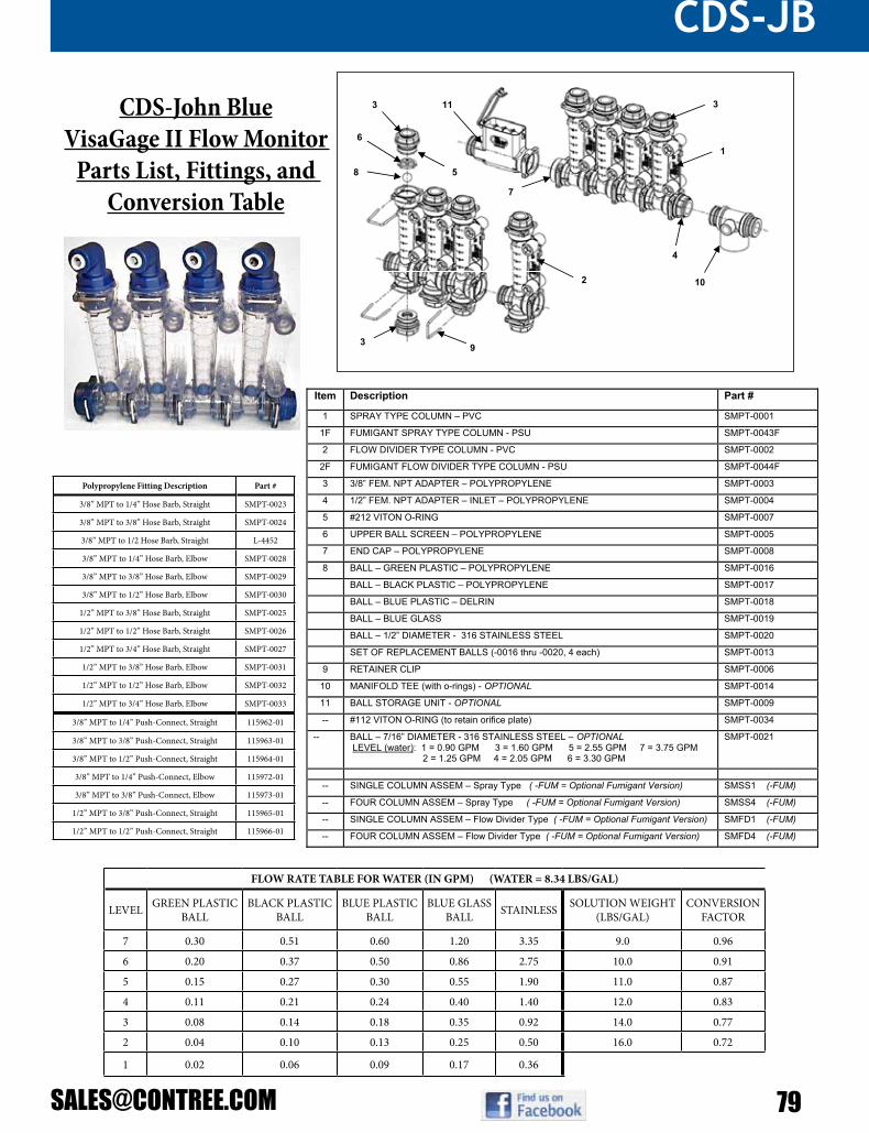
CDS-JB
Parts Breakdown:
Item Description Part #
1 SPRAY TYPE COLUMN – PVC SMPT-0001
1F FUMIGANT SPRAY TYPE COLUMN - PSU SMPT-0043F
2 FLOW DIVIDER TYPE COLUMN - PVC SMPT-0002
2F FUMIGANT FLOW DIVIDER TYPE COLUMN - PSU SMPT-0044F
3 3/8” FEM. NPT ADAPTER – POLYPROPYLENE SMPT-0003
4 1/2” FEM. NPT ADAPTER – INLET – POLYPROPYLENE SMPT-0004
5 #212 VITON O-RING SMPT-0007
6 UPPER BALL SCREEN – POLYPROPYLENE SMPT-0005
7 END CAP – POLYPROPYLENE SMPT-0008
8 BALL – GREEN PLASTIC – POLYPROPYLENE SMPT-0016
BALL – BLACK PLASTIC – POLYPROPYLENE SMPT-0017
BALL – BLUE PLASTIC – DELRIN SMPT-0018
BALL – BLUE GLASS SMPT-0019
BALL – 1/2” DIAMETER - 316 STAINLESS STEEL SMPT-0020
SET OF REPLACEMENT BALLS (-0016 thru -0020, 4 each) SMPT-0013
9 RETAINER CLIP SMPT-0006
10 MANIFOLD TEE (with o-rings) - OPTIONAL SMPT-0014
11 BALL STORAGE UNIT - OPTIONAL SMPT-0009
-- #112 VITON O-RING (to retain orifice plate) SMPT-0034
-- BALL – 7/16” DIAMETER - 316 STAINLESS STEEL – OPTIONAL LEVEL (water): 1 = 0.90 GPM 3 = 1.60 GPM 5 = 2.55 GPM 7 = 3.75 GPM 2 = 1.25 GPM 4 = 2.05 GPM 6 = 3.30 GPM
SMPT-0021
-- SINGLE COLUMN ASSEM – Spray Type ( -FUM = Optional Fumigant Version) SMSS1 (-FUM)
-- FOUR COLUMN ASSEM – Spray Type ( -FUM = Optional Fumigant Version) SMSS4 (-FUM)
-- SINGLE COLUMN ASSEM – Flow Divider Type ( -FUM = Optional Fumigant Version) SMFD1 (-FUM)
-- FOUR COLUMN ASSEM – Flow Divider Type ( -FUM = Optional Fumigant Version) SMFD4 (-FUM)
10
1
113
6
93
2
8
3
4
5
7
FLOW RATE TABLE FOR WATER (IN GPM) (WATER = 8.34 LBS/GAL)
LEVEL GREEN PLASTIC BALL
BLACK PLASTIC BALL
BLUE PLASTIC BALL
BLUE GLASS BALL STAINLESS SOLUTION WEIGHT
(LBS/GAL)CONVERSION
FACTOR
7 0.30 0.51 0.60 1.20 3.35 9.0 0.96
6 0.20 0.37 0.50 0.86 2.75 10.0 0.91
5 0.15 0.27 0.30 0.55 1.90 11.0 0.87
4 0.11 0.21 0.24 0.40 1.40 12.0 0.83
3 0.08 0.14 0.18 0.35 0.92 14.0 0.77
2 0.04 0.10 0.13 0.25 0.50 16.0 0.72
1 0.02 0.06 0.09 0.17 0.36
CDS-John BlueVisaGage II Flow Monitor
Parts List, Fittings, and Conversion Table
Polypropylene Fitting Description Part #
3/8” MPT to 1/4” Hose Barb, Straight SMPT-0023
3/8” MPT to 3/8” Hose Barb, Straight SMPT-0024
3/8” MPT to 1/2 Hose Barb, Straight L-4452
3/8” MPT to 1/4” Hose Barb, Elbow SMPT-0028
3/8” MPT to 3/8” Hose Barb, Elbow SMPT-0029
3/8” MPT to 1/2” Hose Barb, Elbow SMPT-0030
1/2” MPT to 3/8” Hose Barb, Straight SMPT-0025
1/2” MPT to 1/2” Hose Barb, Straight SMPT-0026
1/2” MPT to 3/4” Hose Barb, Straight SMPT-0027
1/2” MPT to 3/8” Hose Barb, Elbow SMPT-0031
1/2” MPT to 1/2” Hose Barb, Elbow SMPT-0032
1/2” MPT to 3/4” Hose Barb, Elbow SMPT-0033
3/8” MPT to 1/4” Push-Connect, Straight 115962-01
3/8” MPT to 3/8” Push-Connect, Straight 115963-01
3/8” MPT to 1/2” Push-Connect, Straight 115964-01
3/8” MPT to 1/4” Push-Connect, Elbow 115972-01
3/8” MPT to 3/8” Push-Connect, Elbow 115973-01
1/2” MPT to 3/8” Push-Connect, Straight 115965-01
1/2” MPT to 1/2” Push-Connect, Straight 115966-01

MICRO-TRAK
80 800-433-3579
Micro-Trak SafeGuard Blockage Monitor
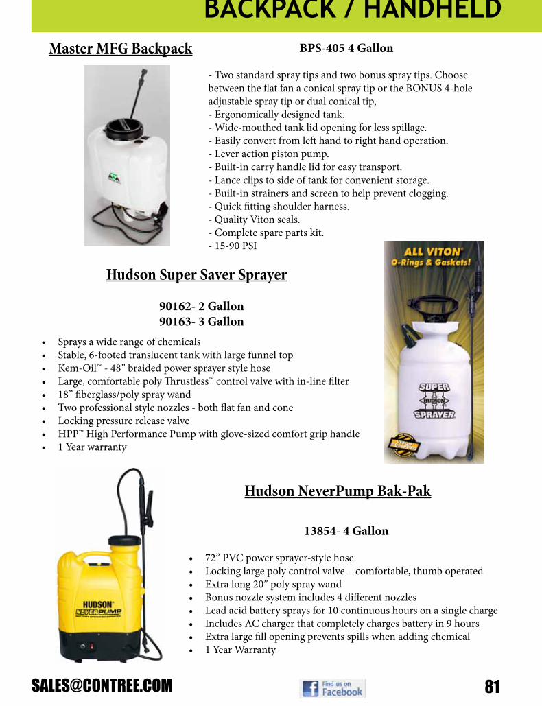
BACKPACK / HANDHELD
BPS-405 4 Gallon
- Two standard spray tips and two bonus spray tips. Choose between the flat fan a conical spray tip or the BONUS 4-hole adjustable spray tip or dual conical tip,- Ergonomically designed tank.- Wide-mouthed tank lid opening for less spillage.- Easily convert from left hand to right hand operation.- Lever action piston pump.- Built-in carry handle lid for easy transport.- Lance clips to side of tank for convenient storage.- Built-in strainers and screen to help prevent clogging.- Quick fitting shoulder harness.- Quality Viton seals.- Complete spare parts kit.- 15-90 PSI
Master MFG Backpack
90162- 2 Gallon90163- 3 Gallon
• Sprays a wide range of chemicals• Stable, 6-footed translucent tank with large funnel top• Kem-Oil™ - 48” braided power sprayer style hose• Large, comfortable poly Thrustless™ control valve with in-line filter• 18” fiberglass/poly spray wand• Two professional style nozzles - both flat fan and cone• Locking pressure release valve• HPP™ High Performance Pump with glove-sized comfort grip handle• 1 Year warranty
Hudson Super Saver Sprayer
13854- 4 Gallon
• 72” PVC power sprayer-style hose• Locking large poly control valve – comfortable, thumb operated• Extra long 20” poly spray wand• Bonus nozzle system includes 4 different nozzles• Lead acid battery sprays for 10 continuous hours on a single charge• Includes AC charger that completely charges battery in 9 hours• Extra large fill opening prevents spills when adding chemical• 1 Year Warranty
Hudson NeverPump Bak-Pak

WILGER
82 800-433-3579
FLOW VIEW™ Flow Indicator Assemblies, Fittings, Components, Metering Orifices and Accessories
Makers of Better EngineeredSprayer Components for over 35 Years
SPECIFICATIONSMaterials:Indicator Body: UV & chemically resistantFittings: Polypropylene and Celcon®Indicator Balls: Polypropylene (orange & green); Celcon (red); Glass (maroon); Stainless Steel (7/16” & 1/2”) O-ring Seal: Buna-N or VitonU-Clip: Stainless steelMax operating pressure: 100 psi / 7 BarMax operating temperature: 185F / 85C
Flow Indicator Body and Indicator Ball Selector Guide
PART No.with
BUNA-N-SEAL
withVITONSEAL FLOW INDICATOR ASSEMBLY and PARTS
20460-00 20460-V0 FLOW INDICATOR ASSY (Includes Body, Ball Retainer, O-Ring, 2 Lock U-Clips and Green, Red & 1/2” Stainless Steel Balls)
20470-00 20470-00 FLOW INDICATOR ASSY - LOW FLOW (Includes Body, Ball Retainer, O-Ring, 2 Lock U-Clips; and Green, Red & 1/2” Stainless Steel Balls)
20480-00* 20480-00* FLOW INDICATOR ASSY - ISOLATED FEED (Includes Body, Ball Retainer, 1 Lock U-Clip; and Green, Red & 1/2” Stainless Steel Balls)
20490-00* 20490-00* FLOW INDICATOR ASSY - ISOLATED FEED - LOW FLOW (Includes Body, Ball Retainer, 1 Lock U-Clip; and Green, Red & 1/2” Stainless Steel Balls)
20460-01* 20460-01* FLOW INDICATOR BODY
20470-01* 20470-01* FLOW INDICATOR BODY - LOW FLOW
20480-01* 20480-01* FLOW INDICATOR BODY - ISOLATED FEED
20490-01* 20490-01* FLOW INDICATOR BODY - ISOLATED FEED - LOW FLOW
20460-04* 20460-04* LOCK U-CLIP,302SS
20460-02* 20460-02* BALL RETAINER
20460-03 20460-15 O-RING - #212 (for Indicator Body and Fittings)*Seal Not Applicable
O-RING SEAL (ORS) FITTING ASSEMBLIES(includes required seals and/or U-clips)
20501-00 20501-V0 ORS x HOSE BARB - STRAIGHT - 3/8”
20502-00 20502-V0 ORS x HOSE BARB - STRAIGHT - 1/2”
20503-00 20503-VO ORS x HOSE BARB - STRAIGHT - 3/4”
20511-00 20511-V0 ORS x HOSE BARB - 90 DEGREE - 3/8”
20512-00 20511-V0 ORS x HOSE BARB - 90 DEGREE - 1/2”
20514-00 20514-V0 ORS x HOSE BARB - 90 DEGREE - 5/8”
20513-00 20513-V0 ORS x HOSE BARB - 90 DEGREE - 3/4”
20516-00 20516-V0 ORS MALE x 1/4” PUSH-IN TUBE - 90 DEGREE
20517-00 20517-V0 ORS MALE x 3/8” PUSH-IN TUBE - 90 DEGREE
20518-00 20518-V0 ORS MALE x 1/4” NPTF - 90 DEGREE
20519-00 20519-V0 ORS MALE x 1/4” NPTF
CONNECTOR TEES, STREET ELBOW and END CAP
20520-00 20520-V0 ORS MALE x ORS FEMALE - 90 DEGREE
20522-00 20522-V0 ORS MALE x ORS MALE x ORS FEMALE - TEE
20523-00 20523-V0 ORS MALE x ORS FEMALE (BLIND) x 3/8” NPTF - ISOLATOR TEE
20524-00 20524-V0 ORS MALE x ORS FEMALE x 3/8” NPTF - TEE
20525-00 20525-V0 ORS MALE x ORS MALE x 1” NPTF - TEE
20526-00 20526-V0 ORS MALE x ORS MALE x ORS FEMALE - TEE w 1/4” NPTF PORT
20521-00* 20521-00* ORS CAP
20535-00* 20535-00* FITTING ASSEMBLY - ORS FEMALE x 1/4” NPTF
20536-00* 20536-00* FITTING ASSEMBLY - ORS FEMALE x 3/8” NPTF
20537-00* 20537-00* FITTING ASSEMBLY - ORS FEMALE x 1/2” NPTF*Seal Not Applicable
RADIALOCK INLET CAPS (ISOLATED FLOW MODELS)Requires 40261-00 Adapter when no pre-orifice is used
40273-05* RADIALOCK CAP - 1/4” NPTF
40274-05* RADIALOCK CAP - 1/4” NPTF, 45 DEGREE
40277-05* RADIALOCK CAP - 1/8” NPTF
40420-05* RADIALOCK CAP - 1/8” HOSE BARB
40422-05* RADIALOCK CAP - 1/4” HOSE BARB
40424-05* RADIALOCK CAP - 3/8” HOSE BARB
40426-05* RADIALOCK CAP - 1/2” HOSE BARB
40435-05* RADIALOCK CAP - 1/4” TUBE ADAPTER
40436-05* RADIALOCK CAP - 3/8” TUBE ADAPTER
40260-00 40260-V0 NOZZLE SEAL (VITON recommended for fertilizer)
40261-00 SEAL / STRAINER ADAPTER
FLOW INDICATOR BALLSSee Flow Indicator Body and Indicator Ball Selector Chart
20460-13 BALL-FLOW INDICATOR - ORANGE POLYPROPYLENE
20460-08 BALL-FLOW INDICATOR - GREEN POLYPROPYLENE
20460-07 BALL-FLOW INDICATOR - RED CELCON
20460-06 BALL-FLOW INDICATOR - MAROON GLASS
20460-05 BALL-FLOW INDICATOR - 1/2” STAINLESS STEEL 302
20460-10 BALL-FLOW INDICATOR - 7/16” STAINLESS STEEL 302
FLOW VIEW CHECK VALVES andFLOW INDICATOR FLOW METERING ORIFICES
21000-00 21000-V0 ORIFICE INSERT ASSEMBLY - BLANK
21XXX-00 21XXX-V0 ORIFICE INSERT ASSEMBLY**
40225-04 40225-05 O-RING - #015 (For Orifice Inserts)
24000-00 24000-V0 CHECK VALVE ASSEMBLY
24XXX-00 24XXX-V0 ORIFICE INSERT ASSEMBLY with CHECK VALVE****Please enquire for sizes and part numbers
PART # BALL COLOR AND MATERIAL FLOW FLOW INDICATOR BODY FLOW RATE - USGPM
20460-13 ORANGE POLYPROPYLENELOW 20470-00 and 20490-00 0.03 - 0.09
STANDARD 20460-00 and 20480-00 0.05 - 0.18
20460-08 GREEN POLYPROPYLENELOW 20470-00 and 20490-00 0.03 - 0.09
STANDARD 20460-00 and 20480-00 0.05 - 0.18
20460-07 RED CELCONLOW 20470-00 and 20490-00 0.05 - 0.14
STANDARD 20460-00 and 20480-00 0.09 - 0.30
20460-06 MAROON GLASSLOW 20470-00 and 20490-00 0.10 - 0.18
STANDARD 20460-00 and 20480-00 0.31 - 0.72
20460-05 1/2” STAINLESS STEEL 302LOW 20470-00 and 20490-00 0.15 - 0.70
STANDARD 20460-00 and 20480-00 0.40 - 1.33
20460-10 7/16” STAINLESS STEEL 302LOW 20470-00 and 20490-00 N/A
STANDARD 20460-00 and 20480-00 1.00 - 2.70
Wilger Flow View Ball Indicators

RAVEN
FEATURES• 6.4” color LCD touch-screen• Integrated DGPS sub-meter receiver (WAAS) or unlockable RTK• Optional E-dif correction• Down-field and Birds-eye view• LastPass pattern, the ultimate in contour guidance• Switch between straight A-B guidance and Last pass in same field• Pivot pattern• Use with SmarTrax, SmarTrax DM or QuickTrax assisted steering• AccuBoom-automatic boom section control option• Autoboom Glide series-automatic boom height control option• 4 product control; liquid, granular, NH3, injection
Part No. Descr�pt�on 084 117128 Envizio Pro kit w/o GPS 084 063865 Console only w/GPS 084 117141 Helix antenna kit; MBA-3 antenna w/cable 084 115689 Cable; GPS “Y” single to double 084 115746 Cable, Envizio Pro main 084 115745 Cable, Envizio Pro auxilary 084 115744 Cable, Viper Pro/Envizio Pro combination 084 115742 Cable, Old Viper to Envizio Pro interface 084 215094 Cable, E-Pro to Raven console
ENVIzIO PRO II
Raven’s multi-function field computer does it all--integrated RTK precision, advanced planter control capabilities, yield monitoring, 4 product control, optional single-product VRA, wireless Internet capability, and more.
Part No. Descr�pt�on 084 117-5010-009W Kit, Envizio Pro II, MBA-6, WAAS/SBAS 084 117-5010-009K Kit, Envizio Pro II, MBA-6, RTK 084 117-5010-009KG Kit, Envizio Pro II, MBA-6, RTK/GLONASS
Part No. Descr�pt�on 084 115001 Cable, Envizio Pro II chassis interface 084 115915 Cable, Power; Tracked & row crop tractors w/front mounted batteries 084 115936 Cable, Power; 4WD Tractors w/mid mounted batteries 084 115937 Cable, Power, CIH/Challenger/New Holland row crop tractors 084 115938 Cable, Power; JD & Buhler row crop tractors 084 115-4001-085 Cable, Power; Generic row crop tractors (steering & AccuBoom systems only) 084 077062 E-Pro II RTK authorization key 084 063651 MBA6 Antenna only
ENVIzIO PRO II KITS
POWER/CAN CHASSIS CABLES, ENVIzIO PRO II/XL
• Variable rate option-control product using a prescription map• Data logging & reports• Save A-B lines• View coverage maps• USB ports for data transfer, USB thumb drive compatible• RAMTM mount• User-selectable profiles for different machines• Planter Control• SmartYield, Yield monitoring• Slingshot compatable
ENVIzIO PRO KITS/PARTSPart No. Descr�pt�on 084 215095 Cable, E-Pro to Dickey John 084 077031 Envizio Pro variable rate key 084 117059 TM1 tilt sensor 084 1151787 Cable; 20’ helix antenna 084 063101 Patch antenna 084 117182 Node mounting bracket to E-Pro console 084 016149 Quick start guide 084 016148 Envizio Pro manual
(See Viper Pro section for interface cables to other consoles)
ENVIzIO PRO XL KITS
ENVIzIO PRO XLRaven’s new Envizio Pro XL has the same proven operating system as the Envizio Pro II with a larger 10.4 “ touch screen display. Does not include GPS.
084 117-5010-007 Kit, Envizio Pro XL w/o GPS 084 117-5010-007V Kit, Envizio Pro XL w/o GPS; VRA Unlock

RAVEN
84 800-433-3579
The Raven CRUIZER II-the simple, low-cost way to add precision guidance to your operation. Cruizer is a flexible guidance system that can be used for many different on the farm activities including spraying, tillage, and harvest.
CRUIzER BENEFITS & FEATURES • 5.7” color touch sreen display• 3D and 2D graphic swath display along with LED indicator lights• Field review display to verify coverage and identify skips• Easy to understand, Icon based menus and status indicators• Built-in 10 Hz DGPS Phoenix receiver with upgradeability to E-Dif• Single package provides easy mounting and portability• Can be used with both Raven Assisted Steering Products (SmarTrax & Smartsteer)• Provides a low cost sub-meter guidance of 9” pass to pass• Setup wizard• Available tilt sensor to compensate for side hills• Available high gain antenna for difficult reception areas• Lastpass guidance program• SmartBoom, planter controls compatable• Yield monitoring option• New weather resistant model
Cruizer’s lastpass guidance feature is the easiest to use and set up in the industry.The system guides the operator to one swath width from a previously applied area.Operators can easily switch between straight line (A-B) and LastPass, which is idealfor use in terraced fields or grass waterways.
084 117418 Cruizer II RTK w/MBA antenna 084 117247 Cruizer II/patch antenna 084 117249 Cruizer II/Helix antenna 084 117250 Cruizer II/weather resistant/Patch antenna 084 117245 Cruizer II/weather resistant/Helix antenna 084 117141 Helix antenna kit; MBA-3 antenna w/cable 084 117059 Optional TM1 Tilt sensor 084 115791 Cable, Expander less speed 084 115792 Cable, boom sense 084 115793 Cable, Port Exp. w/speed output 084 115794 Cable, Y adap. tilt/boom sense
084 115835 Cable; Cruizer to SmartBoom 084 115870 Cable; Expander Port B/D & CAN, weather resistant only
084 115871 Cable; Expander Port A/C, weather resistant only 084 115886 Cable; Adapter CAN for Cruizer II only 084 1151787 Cable; 20’ Helix 084 115976 Boom sense; Weather resistant Cruizer 084 063101 Patch antenna 084 215090 Cable; Raven speed output 084 215091 Cable; Dickey John speed output 084 016128 Manual, Cruizer 084 420008 Cable; 12 volt power
CRUIzER II
WEATHER RESISTANT
Part No. Descr�pt�on Part No. Descr�pt�on
SmartMDRaven’s new, simple-to-install mechanical drive steering system harnesses the newest technologies to keepyou on track and on line all day long. You’ll benefit from added torque for faster operating speeds, increasedaccuracy and reduced noise. Transfer SmarTrax MD between multiple tractors, including combines, windrowersand more. -Added torque for fast operating speeds and better line acquire-Simple to install and move between machines-3D terrain compensation-Quiet operationORDER NO Descr�pt�on 084 117-5030-020 Kit, SmarTrax MD Kit 084 117-5030-021 Kit, SmarTrax 7/8” SPLINE 36 TOOTH 084 117-5030-022 Kit, SmarTrax 5/8” SPLINE 36 TOOTH

RAVEN
BENEFITS & FEATURES•Ultrasonic boom leveling system with ultrasonic sensor•Available in either CANbus or standard configuration•Simplified calibration procedure, one button automatic calibration•Use Viper, Viper PRO, Envizio Plus /Pro or SCS 4000/5000Series consoles for setup and operation •Hands free operation, just set the boom height and go!
The UltraGlide features ultrasonic sensors, one-button calibration, and simple instal-lation. The ultrasonic sensors dtect ground height and then automatically adjusts the boom with hydraulic pressure. The system is available in CAN or standard configu-ration and can be operated through a Raven Viper, Viper PRO, Envizio Plus/Pro, or SCS 4000/5000 series consoles.
ULTRAGLIDE
084 1177024 UltraGlide controller kit CANbus (Viper, Viper PRO, Envizio Plus/Pro, 4000/5000 series consoles) 084 117923 Kit, Power adapter Tee cable with two terminators (not needed if used with existing CAN systems) 084 117025 Kit and Console to adapt when Viper, Viper PRO, Envizio Plus/Pro, 4000/5000 series console not used 084 117320__ Installation kit (call for machine specific part number and pricing)
CAN DUAL ULTRASONIC SENSOR KITS 084 117-0137-XXX CAN UltraGlide kits do not include wheel kits. Add-on wheels can be added. Dual sensor kits available for 120’ booms
MISCELLANEOUS PARTS084 063-0130-009 Ultrasonic sensor only 084 063-0130-012 Ultrasonic sensor; Right 084 063-0130-013 Node; CAN autoboom Ultraglide 084 063-0130-014 Ultrasonic sensor; Left 084 063-0130-018 Ultrasonic sensor; Center
JOHN DEERE ISO CANbus KITS Powerglide Plus- Call for pricing with year, model of machine Ultraglide Kit- Call for pricing with year, model of machine
VIPER 4
Viper® 4 integrates with Raven’s full line of products into one networked platform that offers a responsive touchscreen and an intuitive, tablet-style interface with swiping features and horizontal or vertical orientation. Customize your Viper® 4 by user and machine - it’s colorblind which means it works with equipment of every brand. Easy job set-up, fewer touches, and greater efficiency allow for extraordinary data management capabilities.-Sleek new design - 12.1” LED backlit display with responsive touchscreen-Raven Operating System featuring customizable interface for portrait or landscape orientation-State-of-the-art, rugged magnesium alloy enclosure-Dustproof for tough environments-An abundance of storage capacity-4 camera inputs for monitoring bin levels, blind spots, etc.-2 USB ports-Slingshot® ready Part No Descr�pt�on 084 117-5010-010W Kit, Viper 4 with GPS with MBA-6 Antenna 084 115023 Cable, Viper 4 adapter to Viper Pro / Envizio Pro
PRECISION AG SYSTEMS

RAVEN
86 800-433-3579
AUTOBOOM “GLIDE SERIES”
POWERGLIDE PLUS
BENEFITS & FEATURES• Pressure based boom leveling system•Available in either CANbus or standard configuration•Simplified calibration procedure•Use Viper PRO, Envizio Plus/PRO, or SCS4000/5000 series consoles for operation•Easy hook up, simple 4 pin connector to CANbus•Suspension wheel system•Hands free operation, just set the boom height and go!
POWERGLIDEThe PowerGlide system features a compact, easy-to-use console and independent left and right engaging. It is ideal for trailed or self-propelled sprayers and is a great entry-level system. It is also upgrade able to the PowerGlide Plus or UltraGlide system.
•Low cost Autoboom leveling kit
•One button engage
•Compact console, takes up less space in cab
•Easy to use and adjust
•Great for trailed or self-propelled sprayers
•Optional suspension wheel
BENEFITS AND FEATURES
Autoboom allows you to spray faster and more accurately by automatically adjusting the height of your spray booms as you travel across the field. This means that you spend less time watching your booms and trying to prevent them from hitting the ground or crop. Autoboom detects changes in ground height and adjusts your boom height accordingly. Not only can you decrease driver fatigue and wear and tear on your machine, but you increase the accuracy and coverage of the application. It’s a simple one-touch operation, allowing you to just sit back and drive.
A Powergl�de system cons�sts of 1 each of the follow�ng:084 1177022 PowerGlide Controller kit with cables084 117310__ Axle kit (call for machine specific part number and pricing)084 117300__ Installation kit (call for machine specific part number and pricing)
The PowerGlide Plus system boasts all the same featuresas the PowerGlide system, but is available in either CANor standard configuration. The CAN configuration can beoperated through a Raven Viper PRO, Envizio Plus/PRO, or SCS 4000/5000 consoles.
084 117023 PowerGlide Plus controller kit CANbus (Viper PRO, Envizio Plus/Pro, 4000/5000series consoles)084 117923 Kit, Power adapter Tee cable with two terminators (not included in above kit)084 117025 Kit and Console to adapt when Viper/PRO, Envizio Plus/Pro, 4000/5000 series console not present (084 117923 may not be needed) 084 117310__ Installation kit (call for machine specific part number and pricing) (above kits include suspension wheel struts unless noted)
Not seeing the Raven product you need??
We carry the whole line of Raven Industries Precision Equipment! Just call or e-mail our knowledgeable sales staff and we can order the part for you.

RAVEN
SCS103 CONTROLLER
ORDER NO 084 SCS103
The SCS103 enables you to control the spray boom from your cab. Con-sists of 3 individual boom switches and 1 master.
The SCS203 allows boom control of up to three individual sections with a master switch to control all. Pressure control is also included in the unit. Cables are 8’ console and 6’ to valves. (SCS203L cables are 8’ console and 12’ to valves.)
SCS203 CONTROLLER
The SCS330 provides automatic control of chemical application rate regardless of vehicle speed. The SCS330 controls up to 3 booms, pro-vides “on command” display of gallons per acre being applied, distance traveled, vehicle speed, total volume applied, and total area worked. Standard System includes 15 GPM 1” flowmeter, 3/4” control valve, and single 16’ control cable. Any Raven flowmeter, control valve, or 440 harness configuration may be combined with SCS330 Control System to match your particular application.
SCS330 CONTROLLER
ORDER NO. DESCRIPTION 084 SCS203 203 w/6 ft secondary 084 SCS203L 203 w/12 ft Secondary
CABLES084 115013 6’ Final 084 115015 12’ Final 084 107025 12’ Extension cable
ORDER NO. DESCRIPTION 084 412037 Master switch 084 412038 Boom switch 084 412052 Man/Auto switch 084 412053 Inc/Dec switch 084 063116 Faceplate Assy 084 064535 Display Board 084 064534 Processor Board
ORDER NO. DESCRIPTION 084 SCS330 330 assembly 084 063115 Console Only
CABLES084 115437 16’ Cable 084 115706 32’ Cable
ORDER NO. DESCRIPTION 084 063001 3/4” 360o Butterfly Valve 084 417002 Pressure gauge 084 417018 Pressure gauge liquid filled 084 412037 Master switch 084 412039 Pressure switch 084 333004A Gauge fitting-1/8” 084 333008 Union fitting 084 115010 Console cable 084 333007 Male fitting-1/4” 084 510003A Fuse holder
ORDER NO. DESCRIPTION 084 SCS11 SCS11 Controller
SCS11 CONTROLLERThe SCS11 Combines on/off control plus the advantage of “in the cab” pressure control. This unit operates one boom control valve. Ideal for incorporation units. 16’ of signal cable is standard.
ORDER NO. DESCRIPTION 084 417004 Pressure gauge 084 412038 On/off switch 084 412041 Pressure switch 084 333006 Gauge fitting-1/4” 084 333007 Male fitting-1/4” 084 510003 Fuse (15 amp) 084 063001 Butterfly valve

RAVEN
88 800-433-3579
The SCS 440 Controller provides automatic control of chemical application rate regardless of vehicle speed. Capable of changing from RATE1 to RATE2 with a flip of a switch. Also provides “on-command” display of volume remaining in tank, time, total area worked, total volume applied, field area, field volume, vehicle speed, distance traveled, area worked per hour, and volume per minute. Non-Volatile memory and fast valve feature are standard.Beyond these functions the SCS 440 Console with serial port allows for two way transmission of data with other devices such as GPS Systems like the Raven Data Boy and Viper Pro Systems. When linked to these systems it supplies a simple, fast, and complete application record while also accepting variable rate commands from the Viper Pro user generated prescription maps if desired. The SCS 440 with Serial Port features a longer 28 character display and the ability to display pres-sure with the optional electronic pressure transducer and cables.
ORDER NO. DESCRIPTION FLOW METER REGULATOR PRIMARY CABLE SECONDARY CABLE 084 063183 SCS440 W/Ser�al Port (Console Only) 084 SCS440C SCS440 Kit Poly (1-60GPM) 1” Poly 10’ Console Cable 6’ Valve Cable 3 Boom Console 084 RFM60P 084 063125 084 115418 084 115404
084 SCS440CW SCS440 Kit Poly (1-60GPM) 1” Poly 10’ Console Cable 6’ Valve Cable (Weatherpack end Cables) 084 RFM60P 084 063125 084 115085 084 115858
084 SCS443 SCS440 Kit Poly (3-100GPM) 2” Sta�nless 10’ Console Cable 6’ Valve Cable 3 Boom Console 084 063066 084 0632177 084 115418 084 115404
084 SCS442 SCS440 Kit Poly (15-200GPM) 2” Sta�nless 10’ Console Cable 6’ Valve Cable 3 Boom Console 084 063751 084 0632177 084 115418 084 115404
(Below For Use W�th Standard Valve NH3 K�ts)
084 SCS441AC SCS440 W/Ser�al Port S.S. (1-60GPM) 1 1/4” SS 10’ Console Cable 12’ Valve Cable 3 Boom Console 084 RFM60S 084 063-0173-202 084 115085 084 115800
(Below For Use W�th Fast Valve NH3 K�ts)
084 SCS441FC SCS440 W/Ser�al Port S.S. (1-60GPM) 1 1/4” Fast SS 10’ Console Cable 12’ Valve Cable 3 Boom Console 084 RFM60S 084 063-0173-204 084 115085 084 115800
084 115418 10’ Primary 084 115404 6’ Final 084 115405 12’ Final 084 115409 12’ Extension 084 115414 24’ Extension 084 115016 6’ Flow only 084 115017 12’ Flow only 084 115019 24’ Flow only New Syle SCS 440 Cables W�th Weather Pack Ends084 115085 10’ Primary 084 115858 6’ Final 084 115055 12’ Final 084 115856 12’ Extension 084 115857 24’ Extension 084 115800 12’ sgl valve final NH3 084 115836 12’ Multi valve final NH3
Opt�ons For Pressure Transducer on New Style SCS 440084 422090 Pressure Transducer 084 115153 3’ Console Pressure Cable 084 115152 10’ Console Pressure Cable 084 115176 30’ Console Pressure Cable 084 115151 12’ Final Pressure Cable
084 412048 Power switch 084 412046 Master switch 084 412047 Boom switch 084 412050 Rate switch 084 412049 Inc/Dec switch 084 510018 Fuse holder 084 510003 Fuse (AGC 15) 084 106437 Bracket 084 106438 Knob 084 115415 Polarity reverse cable 084 117444 Update PC Brd G 084 117637 Update Nonvolatile Communication Port
MANUALSOld Style (Two W�ndow D�splay)084 016409 SCS440 Manual (Old Style) New Style (28 Character D�splay)084 016822 SCS440 Manual (New Style)
ORDER NO. DESCRIPTION ORDER NO. DESCRIPTION SCS400/440 CONSOLE CABLES SCS440 Parts
.
SCS 440 ConsoleW�th Ser�al Port Listed below are some of the more common configurations.
RAVEN SCS 440 CONTROLLERS

RAVEN
ORDER NO. DESCRIPTION FLOW METER REGULATOR PRIMARY CABLE SECONDARY CABLE
RAVEN SCS 450 / 460 CONTROLLERS
The SCS 450 gives you all the benefits of a SCS 440 but allows you to control 3 more booms, giving you 6 boom control capability.
L�sted below are some of the more common conf�gurat�ons. (To substitute a component simply subract it and add the desired one.
SCS 460
084 063220 SCS450 W/Ser�al Port (Console ONLY)
084 SCS450C SCS450 W/Ser�al Port Poly (1-60GPM) 1” Poly 10’ Console Cable 6’ Valve Cable 6 Boom Console 084 RFM60P 084 063125 084 115085 084 115495
084 SCS450CW SCS450 W/Ser�al Port Poly (1-60GPM) 1” Poly 10’ Console Cable 6’ Valve Cable (Weather Pack Cable Ends) 084 RFM60P 084 063125 084 115085 084 115086
084 063249 SCS460 W/Ser�al Port (Console ONLY)
084 412048 Power switch 084 412046 Master switch (SCS450) 084 412010 Boom switch (SCS450) 084 412050 Rate switch 084 412049 Inc/Dec switch 084 510018 Fuse holder 084 510003 Fuse (AGC 15) 084 106437 Bracket 084 106438 Knob 084 115415 Polarity reverse cable 084 117638 SCS450 Update Nonvolatile Communication Port084 117625 SCS460 Update Nonvolatile Communication Port
MANUALSOld Style (Two W�ndow D�splay)084 016605 SCS450 Manual 084 016479 SCS460 Manual New Style (28 Character D�splay)084 016831 SCS450 Manual 084 016823 SCS460 Manual
ORDER NO. DESCRIPTION ORDER NO. DESCRIPTION
SCS 450/460 CABLES SCS 450/460 PARTS
084 115085 10’ Primary 084 115495 6’ Final 084 115496 12’ Final 084 115856 12’ Extension 084 115857 24’ Extension
New Syle SCS 450/460 Cables W�th Weather Pack Ends084 115085 10’ Primary 084 115086 6’ Final 084 115129 12’ Final 084 115838 12’ 6 boom NH3 final 084 115840 12’ NH3 extension 4-6 sect 084 115856 12’ Extension 084 115857 24’ Extension
Opt�ons For Pressure Transducer on New Style SCS 450/460084 422090 Pressure Transducer 084 115153 3’ Console Pressure Cable 084 115152 10’ Console Pressure Cable 084 115176 30’ Console Pressure Cable 084 115151 12’ Final Pressure Cable
The SCS 460 also gives you the benifits of a SCS 440 but allows you a total of 7 boom capability. The SCS 460 is used with your existing external boom switches. This keeps you from having to switch two sets of switches to turn on your boom.
The SCS 450/460 Controllers provides automatic control of chemical application rate regardless of vehicle speed. Capable of changing from RATE1 to RATE2 with a flip of a switch. Also provides “on-command” display of volume remaining in tank, time, total area worked, total volume applied, field area, field volume, vehicle speed, distance traveled, area worked per hour, and volume per minute. Non-Volatile memory and fast valve feature are standard. Both have serial port which allows them for two way transmission of data with other devices such as GPS Systems like the Viper Pro System or Envizio Pro.
SCS 450

RAVEN
90 800-433-3579
PHOENIX GPS RECEIVERS
PHOENIX 200
PHOENIX 300
Features and Benef�ts•Sub-meter, single frequency, WAAS receiver•Upgradeable to e-Dif differential correction•Ideal for use with SmarTrax or QuickTrax steering systems•Great receiver for Envizio Plus or RGL Light Bar guidance•Smart Antenna-receiver and antenna are in a single enclosure
Features and Benef�ts•Sub-meter, Dual frequency L1/L2 WAAS, CDGPS, and OmniStar VBS receiver•Upgradeable to decimeter accuracy using Omnistar HP or XP
correction (requires subscription service) •In-cab receiver allows access to configuration and settings•Helix antenna provides better satellite tracking•Provides high accuracy DGPS for SmarTrax and QuickTrak
ORDER NO. DESCRIPTION 084 117071 Phoenix 200 no e-Diff
084 115361 Power Cable
ORDER NO. DESCRIPTION 084 117097 Phoenix 300 WAAS/CDGPS/VBS 084 117091 Phoenix 300 HP/XP Enhancement 084 117303 Phoenix 300 WAAS/CDGPS/HP/XP/RTK w/GLONASS
084 077014 RTK Unlock code (from XP/HP to RTK)
084 077019 HP/XP Upgrade for Phoenix 300 (makes 117097 kit into 117091)084 077021 RTK Unlock code (from WAAS to RTK)
084 1171013 GPS Enhancer Kit
ORDER NO. DESCRIPTION 084 117164 Phoenix 50 no e-Diff Dual Port084 016211 Manual Phoenix 50 084 115819 Power Cable; 15’ dual port
PHOENIX 50The Phoenix 50 GPS receiver provides ground speed as well as standard NMEA GPS output on two serial ports, providing position updates to two external devices up to four t�mes per second.
Not seeing the Raven product you need??
We carry the whole line of Raven Industries Precision Equipment! Just call or e-mail our knowledgeable sales staff and we can order the part for you.

RAVEN
GPS SPEED SENSORSThe Teejet is a 4 Hz GPS speed sensor. Acquisition time is less than 1 minute. Speed range from .5-80mph. Sensor mounts in cab and has power indicator, GPS status indicator, and speed indicator when speed is present.
The Sensor-1 is a 1 Hz GPS speed sensor. It is a WAAS enabled GPS receiver. A great replacement for radar guns, the small 2.4” antenna can be mounted inside or outside the cab. The optional Digital In-Line speed read out model gives the operator true ground speed so that it can be compared to their monitor or tractor. It can be used as a stand alone speed read out or cabled to your sprayer or corn planter monitor with additional cabling. Optional 5 Hz and 10 Hz models available.
ORDER NO. DESCRIPTION
084 117822 RAVEN RADAR II (with power cable) 084 115539 Raven 12’ Power cable
084 TGD DICKEY JOHN RADAR (RVS III)(with Power cable) 084 TG DJ Radar Only (RVS III) 084 500115 DJ Power Cable To Raven Connector
RAVEN RADAR II
RADAR SPEED SENSORS
DICKEY JOHN RADAR RVSIII
SPEED SENSORS
SPEEDOMETER SENSOR 084 063436 COMPLETE, G.M. 084 063134 G.M. (1990 & NEWER) 084 063195 FORD (1990 & NEWER) 084 115743 DODGE (1994 & NEWER) 084 063340 IH, allison transmission ‘94 later
084 063456 Transducer 084 063634 5/8” Transducer 084 063617 7/8” Transducer 084 063770 10’ Switch only
084 063484 COMPLETE (4 Magnet) 084 063539 COMPLETE (2 Magnet) 084 063402 Red (N) magnet 084 063403 Black (S) magnet 084 063438 21’ Switch Only
PROXIMITY SENSOR084 063443 Proximity/Gear Sensor
084 063730 Drive shaft kit 084 063752 Red replacement magnet 084 063753 Black replacement magnet
MAGNETIC WHEEL SPEED SENSOR
DRIVE SHAFT SPEED SENSOR
TeejetSensor-1 Sensor-1 d�g�tal
ORDER NO. DESCRIPTION 097 9002404 Teejet GPS Speed Sensor for Raven 097 9002371 Teejet GPS Speed Sensor for Dickey-john 097 7850155 Antenna only
084 SENSOR1R Sensor 1 GPS speed sensor for Raven 084 SENSOR1D Sensor 1 GPS speed sensor for Dickey-john
084 SENSOR1DD Sensor 1 speed sensor w/digital read out (comes with Dickey john end only; adapters available)
ORDER NO.ORDER NO.
Not seeing the Raven product you need??
We carry the whole line of Raven Industries Precision Equipment! Just call or e-mail our knowledgeable sales staff and we can order the part for you.

RAVEN
92 800-433-3579
ORDER NO. DESCRIPTION
084 115020 6’ Speed Extension (Raven)
084 115032 12’ Speed Extension (Raven)
084 115018 24’ Speed Extension (Raven)
084 115DJ6 6’ Speed Extension (Dickey John)
084 115DJ12 12’ Speed Extension (Dickey John)
084 115DJ24 24’ Speed Extension (Dickey John)
GPS SPEED ADAPTER “Y” CABLES084 115166 Speed adapter (210/310/410/Phoenix 300) Port “B”
084 115216 Speed adapter (RPR 110/115/Phoenix 200) Port “A”
RADAR SPEED SENSOR INTERFACE CABLES
SPEED EXTENTION CABLES
ORDER NO. DESCRIPTION 084 115551 CIH w/Raven radar to 4 pin WP 084 115517 CIH (4 pin sq WP)/NH TG 084 115304 CIH MX, STX/NH TG,TJ 084 115MXR CIH MX in cab to Raven 084 115MXD CIH MX in cab to DJ 084 115432 CIH w/TRW 084 115627 Caterpillar row crop 35, 45, 55
Cat 65C, 75C, 65D, 75D,85D084 115518 Caterpillar 65, 75 084 115580 Caterpillar/Rogator 8.5 ft DJ 084 115754 Ford Gen/NH/Vers w/Rav radar 084 115709 Ford Gen./Versatile/NH w/DJ 084 115529 Ford/White/Agco Allison (DJ) 084 115304 New Holland TG, TJ 084 115MXR New Holland TG, TJ in cab
ORDER NO. DESCRIPTION 084 115550 JD w/Raven radar to 4 pin WP 084 115519 JD w/4 pin WP 084 115700 JD 7000/8000/9000 084 115701 JD 8000/9000 in cab connection 084 215100 JD 30 series 7 pin to Raven 084 215101 JD 30 series 7 pin to DJ 084 215102 JD 30 series 7 pin to Rav & DJ 084 215007 JD Starfire to Raven console 19’ MISCELLANEOUS084 115472 “Y” cable Raven connections 084 115522 Raven power cable 18” 084 115539 Raven power cable 12’ 084 500115 DJ to Raven w/power 084 115526 DJ “Y” to Rav. console w/power 084 115DJY “Y”cable; all DJ connections
PROCEDURE TO TEST SPEED CABLES
•Verify if console is in SP1 or SP2•Hold connector so keyway is at 12 o’clock position•Enter speed cal number of 1000 for SP1 or 9999 for SP2 under speed cal key•Depress DISTANCE key•With small jumper wire, short between the 10 and 6 o’clock pins. Each time a contact is made, the DISTANCE total should increase•Perform voltage tests between 10 & 6 and 10 & 2. Should get 5 volts•If above tests fail replace cable•If above test check good replace/repair speed sensor
KEYWAY
10 O’CLOCK+0 V
GROUND
2 O’CLOCK+ 5V
POWER
6 O’CLOCK+5V
SIGNAL
AccuBoomUsing the Raven VIPER, Viper PRO, Envizio Plus/Pro and GPS positioning technology, the AccuBoom feature automatically turns boom sections on and off in the field according to previously-recorded applied areas. This reduces overlap. With its hands-off con-trol, AccuBoom reduces operator fatigue. Up to 10 boom control with CAN systems. Systems are machine specific and are available for self-propelled and pull type sprayers/spreaders. It requires a Viper, Viper PRO, Envizio Plus, or Envizio Pro to be installed. The Raven touch-screen consoles will also display and data log boom sections as they turn off and on throughout the field. AccuBoom kits have customized cables to allow easy installation with minimal effort and hassle. All kits have been designed using actual machines. This means that cables will be the right length and will have the correct connections for your application. It also means that you must make sure that you have correctly identified the make and model of your sprayer or spreader to avoid issues with incorrect cables. With AccuBoom’s wireless receiver and remote control option, you can check each section by yourself outside the cab. This handy accessory lets you turn each boom section on and off while you are standing right there to see. A system requires five components: 1. Viper, Viper PRO, Envizio Plus, or Envizio Pro. 2. DGPS receiver (4 Hz or faster) 3. Raven SCS rate control console (such as a SCS 440 or SCS4600) or Raven CANbus controller. 4. Machine specific AccuBoom kit (Call for pricing) 5. Choice of 2 AccuBoom control nodes Part# Descr�pt�on 084 063316 AccuBoom control node no remote 084 063714 AccuBoom combo node (*used on 2009 & newer Ag Chem machines and 2010 and newer Spra-Coupe)084 117284 AccuBoom control node w/remote

RAVEN
FLOW MAX 810
AUTOMATIC BATCHER- Now you can bulk load from a nurse truck to a sprayer tank or from a chemical bulk tank to a transport truck automatically and dependably. You simply punch into the Flow Max 810 console the volume of water, chemical, or mixture that you want pumped into the tank and push the start button on the console. The 810 removes the worry of inadvertently overfilling the tank. - An in-line flow meter measures the volume of liquid being pumped through it. The flow meter sends a signal to the 810 control console and when the desired volume is reached the 810 console sends a signal to the shut-off valve to close. - The 810 console is an economical, single product batch controller that provides the same reliable service and quality you have come to expect in other Raven flow control systems. Raven offers a variety of flow meters and on/off valves which allow the Flow Max 810 to accurately meter nearly any batch size. A wide range of flow rates and plumbing sizes can be accommodated. - The decimal locations can be set to display 0000, 000.0, or 00.00 gallons or liters on the four digit data window of the console.
ORDER NO. DESCRIPTION 084 063214 Console 084 115763 Console Cable 084 115762 Flow Control Cable 21’ 084 115764 Ext. Control Cable 10’ 084 115018 Speed Extension 24’ (Receiver ext.) 084 115032 Speed Extension 12’ (Receiver ext.)
- Now you can bulk load from a nurse truck to a sprayer tank or from a chemical bulk tank to a transport truck economically and dependably. - The Flow Max 110 measures the liquid being pumped from one tank to another. An in-line flow meter provides a signal to the 110 monitor which displays a readout in either gallons or liters. - The 110 console is economical, single product flow monitor that provides the same reliable service and quality you have come to expect in other Raven flow control system. Raven offers a variety of flowmeters which allow the Flow Max 110 to accurately meter a wide range of flow rates and accommodate a variety of plumbing sizes. - Installation can be done on the sprayer, nurse tank unit, or the chemical fill plant. Operate on either 12V, DC, or with a standard 110V, AC conversion kit.FEATURES DISPLAY FEATURES- Quick and easy installation and programming - Batch volume- Weather resistant enclosure - Rate of flow- Backlit display window - Total volume measure- 20’ power cable - Sub volume measured- 20’ meter cableORDER NO. DESCRIPTION 084 063357 Flow Max 110 assembly
FLOW MAX 110 FLOW MONITOR CONSOLE
DISPLAY FEATURES- Volume remaining in tank.- Rate of flow- Total and sub volumes measured
- Non-volatile memory.- Optional, wireless start, stop remote control.- Optional cable lengths to fit your requirements.
ORDER NO. DESCRIPTION
084 0632123 Flowmax 220
084 507006 Replacement battery
(requires 1 battery)
FEATURES- Start, stop and clear batch controls.- Programmable batch size.- Pre-cutoff setting to ensure accurate batch volume.- Quick and easy installation and programming
The Flow Max 220 measures the liquid pumped from one tank to another while providing a self contained digital display with 6 digits indicating flow rate and 3 totals. The indication can be displayed in either gallons or liters. Max total displayed 999,999 gal. or liters. Installation can be directly mounted in line on the sprayer, nurse truck, or chemical fill tank. It operates using a single internal and replace-able s�ngle 3.6V long l�fe battery that will last for over 1.5 million gallons total throughput. Comes with 220 flange or 2” fpt. Max flow 200 gpm. .
RAVEN FLOW MAX 220 BANJO 2” FULL PORT MAG METER
ORDER NO. DESCRIPTION
102 MFM100 1” Mag meter w/1” flanges 110 GPM
102 MFM220 2” Mag meter w/220 flanges 300 GPM
102 MFM300 3” Mag meter w/300 flanges 670 GPM
•Displays overall total volume & batch total volume•Flow rate allows for gallons or liters per minute•Digital readout in Metric or English•Magnetic style with stainless steel electrodes•Self calibrating meter•Measures water and most conductive liquids•Easy to change (6) AA batteries•No moving parts to fail during use•Glass-reinforced polypropylene•Temperature range from 0o to 150oF•Accuracy is 99%

RAVEN
94 800-433-3579
FLOW METERS
RFM100 POLY FLOWMETER2” FPT Poly, 3-100GPM, 150 PSI
084 063066 Complete 084 063002 Rotor only 084 219140 Hub O’ring 084 321222 Hub w/Bearings 084 063082 Stud Bearing 084 219238 Body O’ring 084 219018 O-ring, x-ducer 084 117567 Plug/Pc Assy 084 107005 Hub Housing, Inlet 084 435032 Band Clamp 084 325016 Saphire Bearing 084 117441 Cable Kit
RFM60S
RFM15
RFM200 POLY
084 2192030 Xder O’Ring 084 063749 Transducer 084 117020 Rotor only 084 063563 Hub/inner bearings 084 063062 Stud bearing 084 219042 Inlet oring (viton) 084 063776 Hub Housing (obsolete) 084 325005 Inner hub sapphire 084 219040 Outlet oring (Old) 084 325012 Tungsten bearing
RFM15 POLY FLOWMETER1 1/2” FPT X 2” Flange Poly .3-15 GPM, 300 PSI
084 RFM15F Complete 084 106550 Poly Body 084 063041 Rotor 084 063674 Hub/Bearing Assy 084 063769 Rotor Stop & Brg 084 335278 Snap Ring 084 063062 Stud Bearing 084 063669 Sensor Assy
RFM60P and RFM60S1 1/2” FPT X 2” Flange Poly, 1-60GPM, 175 PSI 1 1/2” Sta�nless, 1-60GPM, 300 PSI
084 RFM60P Poly Complete 084 RFM60S Complete Sta�nless 084 106514 Poly Body 084 063673 Rotor 084 063674 Hub/Bearing Assy 084 063769 Rotor Stop & Brg 084 335278 Snap Ring 084 063062 Stud Bearing 084 063669 Sensor Assy
RFM200 POLY FLOWMETER3” FPT Poly, 15-200GPM, 90 PSI
084 063751 COMPLETE 084 219051 Oring (EPDM) 084 219052 Oring (viton) 084 063002 Rotor only 084 063564 Hub w/bearings 084 063575 Stud bearing 084 219040 O-ring, X-ducer 084 063646 Plug/PC assy 084 107618 Hub Housing 084 435031 Retainer Clamp 084 325006 Turbine bearing 084 117441 Cable Kit
RFM100
RFM55
RFM60P
1) 2) 3) 4) 5) 6) 7) 8) 9)10)
RFM55 POLY FLOWMETER1 1/4” Barb Poly, 1-55 GPM, 200 PSI
084 063571 Complete D�scont�nued084 019085 Sensor Housing 084 311037 10-32x3/4 Screw
1)2)3)4)5)6)7)
12 3
4
5
6 7
8
9
1) 2) 3) 4) 5) 6) 7) 8) 9)10)
1)
2) 3) 4) 5) 6) 7) 8)
12
3
4
5 6
78
7
1)2)3)4)5)6)7) 123
4
6
5
5
4
5 6
7
123
5

RAVEN
MOTORS &PARTS084 0632980 Motor Assy 1” valve Replaces 063144 (may need 115807 adapter cable)
084 063-0173-206 Motor Assy Std for 1 1/4” valve fits 063-0173-202 1 1/4”084 0632982 Motor Assy Fast (4 Wire) Replaces 063146 (may need 084 115807 adapter cable)
084 063257 1” SS Valve Only 084 063209 1 1/4” SS Valve Only
OLD STYLEORDER NO. PART NO, N/A DESCRIPTION084 063173 084 063808 1/4” FPT, Ball, Stainless, .3-15GPM, 300psi 084 0632977 084 063557/168 1” FPT, Ball, NH3, Std 2-100GPM, 400psi 084 063-0173-202 1 1/4” FPT,Ball,NH3, SS, Std 084 0632979 084 063155/170 1” FPT, Ball, NH3, Fast 2-100GPM, 400psi 084 063-0173-204 1 1/4” FPT, Ball, NH3, SS FAST 084 0632177 084 063805 2” FPT, Butterfly, Stainless 5-300GPM, 300psi 084 063181 084 063911 3” FPT, Butterfly, Stainless 20-600GPM, 300psi
STAINLESS STEEL AND CARBON STEEL CONTROL VALVES
REGULATING VALVES
S.S. VALVE
POLY VALVES
FLOW METERS, MAGMETERS, & ENCODERS
RFM200 Cast Mag Meter
Encoder
ORDER NO. DESCRIPTION 084 063574 RFM200 3” Cast flowmeter 15-200GPM MAGMETERS084 063682 220 FLG Magmeter 3-200 GPM (may need 115-0171-750 cable)084 063149 4” Magmeter 35-1500 GPM 084 0633150 6” Magmeter 70-3000 GPM ENCODERS084 063071 180 Pulse/Rev. Encoder 084 063114 36 Pulse/Rev. Encoder GEAR TOOTH SENSOR084 063981 Gear tooth flow sensor
10 O’CLOCK+ 5V
POWER
KEYWAY
2 O’CLOCK+0 V
GROUND
6 O’CLOCK+5V
SIGNAL
PROCEDURE TO TEST FLOW CABLES•Hold connector so keyway is at the 12 o’clock position•Enter a METER CAL number of 1 in meter cal key•Place BOOM switches to ON•With a small jumper wire, short between the 2 and 6 o’clock pins. Each time a contact is made, the TOTAL VOLUME should increase. If volume does not increase check next connection if any. Replace defective cable as required.•Check for 5 volts between 2 & 10 o’clock and 2 & 6 o’clock•If cables test good, replace/repair flow sensor/meter
084 063619 Motor Assy (805/557) 084 106444 Cover (blue) 084 107608 Coupler 1” valve (557) 084 117410 Seal kit 1” old steel valve 084 063257 1” SS valve only Replaces 084 334010
ORDER NO. DESCRIPTION 084 063001 3/4” FPT, 360o Butterfly, Poly 3-15GPM, 150psi 084 063120 3/4” FPT, Butterfly, Poly 3-15GPM, 150psi 084 063125 1” FPT, Butterfly, Poly 3-30GPM, 175psi 084 063165 1” FPT, Stainless ball, Poly 3-30GPM, 175psi 084 0631894 1 1/2” FPT, Butterfly, Poly 7-55GPM, 175psi PARTS 084 117810 1” ISO kit 084 117739 1.5” ISO kit 084 064144 Motor PC board 084 106407 Valve cover 084 219020 Cover tetraseal 084 115415 Polarity reverse cable
OLD STYLE PARTS PRE-2002
084 107393 Coupler 084 107394 Coupler clamp 084 117892 Retro Brkt and Coupler kit 084 115807 Valve adapter cable 084 117219 Indicator decal kit
Mag 200

VALVES
96 800-433-3579
BOOM CONTROL VALVESRAVEN BOOM VALVES
Get Raven reliability and performance with this new boom valve. It has a 40 GPM flow rate at a 5 PSI pressure drop. Close time is .7 seconds. Banjo flange fittings are standard. Outlet has 3/4” FPT and Banjo flanges. It has a working pressure of 175 PSI. Made by Raven in the USA.
ORDER NO. DESCRIPTION 084 063926 Boom valve single unit One clamp and gasket included 084 063928 Boom valve 3 bank unit 084 063039 Boom valve 5 bank unit 084 063330 Replacement motor
Add single units for desired multiple units.
W�r�ng schemat�c: Red - 12V Wh�te-boom s�gnal Black-Ground
W�r�ng schemat�c: Red-12 volts Wh�te-Boom s�gnal Black-ground
12 VOLT MOTORIzED BALL VALVEw�th FLANGES
Polypropylene construction with viton and teflon seals. 1 amp draw during open/close cycle. Max pressure is 200 psi and 32 gpm. Easy mounting with built in brackets. Internal resettable fuse. Internal relay to allow wiring to any sprayer control.
ORDER NO. DESCRIPTION 097 E451 Single 097 E453 Bank of Three 097 E455 Bank of Five 097 E50515 Replacement motor
MOTORIzED SHUT-OFF VALVES
12VDC motor driven shut-off valves with 3/4-3 second response time.
ORDER NO. DESCRIPTION Seconds 097 EC344 1” Poly W/Relay, 300psi .7 102 VE100FP 1”FP BANJO, 150 psi .75 102 MEV100CF 1” Flanged 12V. Banjo .75 084 0632978 1” Carbon steel, 400psi 1.5 084 063-0173-203 1 1/4” Ball, SS, NH3 084 063184 1 1/2” Poly, 125psi 084 063185 2” Polypropylene, 125psi 102 EV300FP 3” Full Port 12 volt, 100 psi 3 102 MEV300CF 3” Manifold 12 volt, 100 psi 1.25 097 344BEC-34-C 3-way 1” ball valve
EC344 0632978
MOTORIzED CONTROL VALVES
12VDC motor driven butterfly or ball regulating valves.ORDER NO. DESCRIPTION 084 063001 3/4” Nylon butterfly, 3600 084 063120 3/4” Butterfly, 600 097 E244C 3/4” Butterfly (3600) 084 063181 3” 316 Stainless Butterfly 084 0632977 1” Carbon steel ball (NH3) 084 063-0173-202 1 1/4” SS ball (NH3) 097 E344R 1” Polypropylene ball valve 084 063125 1” Poly butterfly w/flange 084 0631894 1 1/2” Poly butterfly 084 0632177 2” 316 Stainless butterfly
063001
W�r�ng schemat�c: Red - 12volts (A) Wh�te-ground (B) Black-boom s�gnal (C)
VE100FP
0632977 063125
E344R
0632177
12 VOLT MOTORIzED FLOW BACKBALL VALVE w�th FLANGES
The 450 series flow back valves allow pressure from the boom lines to be relieved back to the tank when the valve is switched to the off position. Max pressure is 200 psi and 32 gpm. Flange connections need to be ordered separately. This valve is ideal for autoboom shut off systems where instant shut off is required..
ORDER NO. DESCRIPTION 097 E451F Single 097 E453F Bank of Three 097 E455F Bank of Five 097 E45529A 1/2” Mnfld barb kit 097 E45529B 3/4 Mnfld barb kit 097 E37166 C-Clip; quick connect 097 E55222 Plug; quick connect 097 E50515 Replacement motor
EV300FP

VALVES
OLD STYLEORDER NO. PART NO, N/A DESCRIPTION 084 0632978 084 063500/169 1” NH3, Ball, Carbon Steel 084 063-0173-203 1 1/4” NH3, Ball Stainless Steel 084 063184 084 063503 1 1/2” Ball, Poly 084 063185 084 063504 2” Ball, Poly 084 063178 084 063506 2” Butterfly, Stainless Steel 084 063182 084 063984 3” Butterfly, Stainless Steel
NEW STYLE PARTS 084 063-0173-207 Motor 1” & 1 1/4” SS
084 107393 Coupler 084 107394 Coupler Clamp
084 063257 1” SS valve only
084 063209 1 1/4” SS valve only
084 115808 Valve adapter cable
084 117892 Retro Brkt and coupler kit
084 117219 Indicator decal kit
084 117355 Seal kit NH3 valve 1 1/4”
OLD STYLEORDER NO. PART NO, N/A DESCRIPTION
STANDARD HYDRAULIC VALVE084 0633159 084 063718/187 Hydraulic Regulating Valve 0-3 GPM 084 0633160 084 063797/188 Hydraulic Regulating Valve 0-8 GPM 084 0632195 084 063715/189 Hydraulic Regulating Valve 0-16 GPM 084 0632196 084 063791/190 Hydraulic Regulating Valve 0-30 GPM
FAST HYDRAULIC VALVE084 0633161 084 063354/191 Fast Hyd Regulating Valve 0-3 GPM 084 0633162 084 063380/192 Fast Hyd Regulating Valve 0-8 GPM 084 0633163 084 063381/193 Fast Hyd Regulating Valve 0-16 GPM 084 0633164 084 063379/194 Fast Hyd Regulating Valve 0-30 GPM
PWM HYDRAULIC VALVE084 063841 084 063354 PWM Hyd Regulating Valve 0-5 GPM 084 063842 084 063380 PWM Hyd Regulating Valve 0-10 GPM 084 063843 084 063381 PWM Hyd Regulating Valve 0-15 GPM 084 063846 084 063379 PWM Hyd Regulating Valve 0-30 GPM
NEW STYLE PARTS OLD STYLE PARTS PRE-2002084 063244 Motor Assy Std (2 Wire) 084 063619 Motor Assy 084 063150 Motor Assy Fast (2 Wire) 084 106444 Cover (blue)
HYDRAULIC & ON/ OFF VALVES
ON/OFF VALVES
HYDRAULIC
ON/OFF BOOM VALVESORDER NO.
DESCRIPTION
084 063926
Single Boom Valve 40 GPM, 175psi
084 063928
3 Section Boom Valve 40 GPM, 175psi
084 063039
5 Section Boom Valve 40 GPM, 175psi
NEW STYLE PARTS
084 106522 Manifold Body 084 107327 Clip 084 219214 Outlet O-Ring 084 106523 Outlet 1” 084 219099 Plunger Seat 084 219010 Plunger O-Ring 084 063330 Motor only
OLD STYLE PARTS PRE 2002
084 063487 Motor assy 084 106426 Cover black 084 117410 Seal kit 1” valve 084 107608 Coupler 1” valve

VALVES
98 800-433-3579
PART NO DESCRIPTION MAX PSI
PIPE SIZE
BALL PORT
¾ Second Response TimeEV075 ¾” Full Port Electric Valve 150 ¾” 1”
EV100FP 1” Full Port Electric Valve 150 1” 1”EV125 1¼” Electric Valve 150 1¼” 1”
4 Second Response TimeEVR075 ¾” Full Port Electric Valve 150 ¾” 1”
EVR100FP 1” Full Port Electric Valve 150 1” 1”EVR125 1¼” Electric Valve 150 1¼” 1”
PART NO DESCRIPTION MAX PSI
PIPE SIZE
BALL PORT
ON/OFF - 1¼ Second Response TimeEV150 1½” Electric Valve 150 1½” 1½”EV200 2” Electric Valve 150 2” 1½”
REGULATING - 4 Second Response TimeEVR150 1½” Electric Valve 150 1½” 1½”EVR200 2” Electric Valve 150 2” 1½”
PART NO DESCRIPTION MAX PSI
PIPE SIZE
BALL PORT
ON/OFF - 1¼ Second Response TimeEV204FP 2” Full Port Electric Valve 150 2” 2”
REGULATING - 4 Second Response TimeEVR204FP 2” Full Port Electric Valve 150 2” 2”
ON/OFF - 3 Second Response Time 3 WireEV300FP 3” Full Port Electric Valve 100 3” 3”
BANJO Electric Valves ¾”-1¼” Threaded
BANJO Electric Valves 1½”-2” Threaded
BANJO Electric Valves 2”-3” Full Port Threaded
PART NO DESCRIPTION MAX PSI
PIPE SIZE
BALL PORT
¾ Second Response Time Bottom Load ValveEV075BL ¾” Full Port Electric Valve 150 ¾” 1”EV100BL 1” Electric Valve 150 1” 1”EV125BL 1¼” Electric Valve 150 1¼” 1”
¾ Second Response Time Side Load ValveEV075SL ¾” Full Port Electric Valve 150 ¾” 1”EV100SL 1” Electric Valve 150 1” 1”EV125SL 1¼” Electric Valve 150 1¼” 1”
BANJO Electric Valves ¾”-1¼” Threaded with Bottom/Side Flange Inlet

VALVES
PART NO DESCRIPTION MAX PSI PIPE SIZE
BALL PORT
V050 ½” Full Port Valve 150 ½” ¾”V075 ¾” Full Port Valve 150 ¾” ¾”V100 1” Standard Port Valve 150 1” ¾”
V100FP 1” Full Port Valve 150 1” 1”V125 1¼” Standard Port Valve 150 1¼” 1”
V125FP 1¼” Full Port Valve 150 1¼” 1½”V150 1½” Full Port Valve 150 1½” 1½”V200 2” Standard Port Valve 150 2” 1½”
VL20153* Locking Device V125FP, V150 & V200
V10270 Straight Mounting Bracket V100FP & V125
V10271 90° Mounting Bracket V100FP & V125
V25270 Straight Mounting Bracket V150 & V200
V25271 90° Mounting Bracket V150 & V200
VRH200K Removable Handle Kit V125FP, V150 & V200
V10153138BL 1” x 13⁄8” Handle Offset V075BL & V100BL
V10153138 1” x 13⁄8” Handle Offset V100FP, V125, V075SL & V100SL
V20153138BL 2” x 13⁄8” Handle Offset MV200BL, V125BL & V150BL
V20153138 2” x 13⁄8” Handle Offset V125FP, V150, V200 V125SL, V150SL
V25153138BL 2” FP x 13⁄8” Handle Offset MV220BL & MV300BL
V25153138 2” FP x 13⁄8” Handle Offset V200FP & V200SL
PART NO DESCRIPTION MAX PSI
THREAD SIZE
BALL PORT
LV025V ¼” Female NPT Micro Valve 300 ¼” 3⁄8”LV038V 3⁄8” Female NPT Micro Valve 300 3⁄8” 3⁄8”LV050V ½” Female NPT Micro Valve 300 ½” 15⁄32”
LV050SLV ½” Side Load Micro Valve 300 ½” ½”LV025MTV ¼” Female x Male NPT Micro Valve 300 ¼” 3⁄8”LV038MTV 3⁄8” Female x Male NPT Micro Valve 300 3⁄8” 3⁄8”
LV038050MTV 3⁄8” Female x ½”Male NPT Micro Valve 300 3 3LV050MTV ½” Female x Male NPT Micro Valve 300 ½” 15⁄32”
LV050100MTV ½” Female x 1” Male NPT Micro 300 ½” 15⁄32”LVHB025V ¼” Hose Barb Micro Valve 300 ¼” 3⁄8”LVHB038V 3⁄8” Hose Barb Micro Valve 300 3⁄8” 3⁄8”LVHB050V ½” Hose Barb Micro Valve 300 ½” 15⁄32”LVHB075V ¾” Hose Barb Micro Valve 300 ¾” 15⁄32”
LVHB038050MTV 3⁄8” Hose Barb x ½” Male NPT Micro Valve 300 3⁄8” 3⁄8”LVHB075MTV ¾” Hose Barb x ¾” Male NPT 300 ¾” ½”
LVHB075100MTV ¾” Hose Barb x 1” Male NPT 300 ¾” 15⁄32”
BANJO Poly Micro Valves
BANJO Poly 4 Bolt Valves

VALVES
100 800-433-3579
PART NO DESCRIPTION MAX PSI
PIPE SIZE
BALL PORT
4 BOLT FULL PORT VALVESV204FP 2” Full Port Valve 150 2” 2”
VFMT204FP 2” Full Port Valve Male NPT x Male Adapter 150 2” 2”
FULL PORT ANSI FLANGE VALVES
VSF200FPAF 2” Full Port Valve Male Adapter x 2” ANSI Flange 100 2” 2”
VSMT200FPAF 2” Full Port Valve Male NPT x 2” ANSI Flange 100 2” 2”
PART NO DESCRIPTIONMAX PSI
PIPE SIZE
BALL PORT
2” STANDARD PORT STUBBY VALVESVSF200 2” Male Adapter x 2” Female NPT 100 2” 1½”
VSMT200 2” Male NPT x 2” Female NPT 100 2” 1½”VSFMT200 2” Male Adapter x 2” Male NPT 100 2” 1½”VSFHB200 2” Male Adapter x 2” Hose Barb 100 2” 1½”
2” FULL PORT STUBBY VALVESVSMT204FP 2” Male NPT x 2” Female NPT 100 2” 2”
VSF204FP 2” Male Adapter x 2” Female NPT 100 2” 2”VS204FP 2” Female NPT x 2” Female NPT 100 2” 2”
VSFMT204FP 2” Male Adapter x 2” Male NPT 100 2” 2”
VSFMT204HSFP2” FP Male Adapter x 2” Male NPT w/ SS Ball,
Stem & Handle 100 2” 2”
BANJO Poly 6 Bolt ValvesPART NO DESCRIPTION MAX PSI PIPE
SIZEBALL PORT
V200FP 2” Full Port Valve 150 2” 2”V300 3” Standard Port Valve 100 3” 2½”
V300FP 3” Full Port Valve 100 3” 3”V400 4” Standard Port Valve 75 4” 3½”
VFMT200FP 2” Full Port Valve w/ “F” Adapter 150 2” 2”
VFMT200FPSH 2” Full Port Valve w/ “F” Adapter 150 2” 2”
VL25153* Locking Handle V200FP, V300, V300FP, V400, VFMT200FP, & VFMT200FPSH
V25270 Straight Mounting Bracket V200FP, V300, V300FP, V400, VFMT200FP & VFMT200FPSH
V25271 90° Mounting Bracket V200FP, V300, V300FP, V400, VFMT200FP & VFMT200FPSH
VRH220K Removable Handle Kit V200FP, V300 & V300FP
BANJO 2” Full Port Poly Bolted Ball Valve & ANSI Flange Valves
BANJO 2” Standard & Full Port “Stubby” Valves

VALVES
PART NO DESCRIPTION MAX PSI
PIPE SIZE
BALL PORT
3” STANDARD PORT STUBBY VALVESVSMT300 3” Female NPT x 3” Male NPT 100 3” 2½”
VSF300 3” Female NPT x 3” Male Adapter 100 3” 2½”VSFMT300 3” Male NPT x 3” Male Adapter 100 3” 2½”
3” FULL PORT PORT STUBBY VALVESVSFMT300FP 3” FP Male Adapter x 3” Male NPT 100 3” 3”
VSFMT300HSFP 3” FP Male Adapter x 3” Male NPT w/SS ball, Stem & Handle 100 3” 3”
PART NO DESCRIPTION MAX PSI
PIPE SIZE
BALL PORT
HANDLE TYPE
3 WAY BOTTOM LOAD VALVESV075BL ¾” 3-Way Bottom Load Poly Valve 100 ¾” 1” TV100BL 1” 3-Way Bottom Load Poly Valve 100 1” 1” TV125BL 1¼” 3-Way Bottom Load Poly Valve 100 1¼” 1½” TV150BL 1½” 3-Way Bottom Load Poly Valve 100 1½” 1½” TV200BL 2” 3-Way Bottom Load Poly Valve 100 2” 2” Straight
VT200BL 2” 3-Way Bottom Load Poly Valve 100 2” 2” T3 WAY SIDE LOAD VALVES
V075SL ¾” 3-Way Side Load Poly Valve 100 ¾” 1” StraightV100SL 1” 3-Way Side Load Poly Valve 100 1” 1” Straight
VT100SL 1” 3-Way Side Load Poly Valve 100 1” 1” TV125SL 1¼” 3-Way Side Load Poly Valve 100 1¼” 1½” TV150SL 1½” 3-Way Side Load Poly Valve 100 1½” 1½” TV200SL 2” 3-Way Side Load Poly Valve 100 2” 2” Straight
VT200SL 2” 3-Way Side Load Poly Valve 100 2” 2” T
BANJO 3” Standard & Full Port “Stubby” Valves
BANJO 3-Way Poly Valves

VALVES
102 800-433-3579
PART NO DESCRIPTION MAX PSI
PIPE SIZE
BALL PORT
SINGLE UNION POLY VALVESSUV050FP ½” Full Port Union Valve 100 ½” ½”SUV075FP ¾” Full Port Union Valve 100 ¾” ¾”SUV100FP 1” Full Port Union Valve 100 1” 1”SUV125FP 1¼” Full Port Union Valve 100 1¼” 1¼”SUV150FP 1½” Full Port Union Valve 100 1½” 1½”SUV200FP 2” Full Port Union Valve 100 2” 2”
SPINWELD POLY VALVES, EPDM Stem O-ringUV050FP ½” Single Union Poly Valve, EPDM Stem O-ring 100 ½” ¾”UV075FP ¾” Single Union Poly Valve, EPDM Stem O-ring 100 ¾” ¾”UV100FP 1” Single Union Poly Valve, EPDM Stem O-ring 100 1” 1”UV125FP 1¼” Single Union Poly Valve, EPDM Stem O-ring 100 1¼” 1½”UV150FP 1½” Single Union Poly Valve, EPDM Stem O-ring 100 1½” 1½”UV200FP 2” Single Union Poly Valve, EPDM Stem O-ring 100 2” 2”
SPINWELD POLY VALVES, FKM (viton type) Stem O-ringWSFMT200 2” Male Adapter x 2” Male NPT Standard Port 150 2” 1½”
WSFMT200FP 2” Male Adapter x 2” Male NPT Full Port, FKM (viton type) Stem O-ring 150 2” 2”
PART NO DESCRIPTION MAX PSI
PIPE SIZE
BALL PORT
FEMALE NPT
1½” & 2” POLY NOZZLE VALVES W/90° ELBOWVA150 1½” Nozzle Valve w/90° Elbow 150 1½”x 8” 1½” 1½”
VA200/150 2” x 1½” Nozzle Valve w/90° Elbow 150 1½”x 8” 1½” 2”x 1½”VA200 2” Nozzle Valve w/90° Elbow 150 2” x 8” 1½” 2”
VA200FP 2” FP Nozzle Valve w/90° Elbow 150 2” x 8” 2” 2”1” POLY NOZZLE VALVES W/45° ELBOW
VA100 1” Nozzle Valve w/45° Elbow 150 1” ¾” 1”UVA100FP 1” FP EPDM Nozzle Valve w/45° Elbow 100 1” 1” 1”
BANJO Poly Nozzle Valves
BANJO Single Full Port Poly & Union Poly Valves
PART NO DESCRIPTION MAX PSI
PIPE SIZE
BALL PORT
VSS025 ¼” SS Full Port Ball Valve 1000 ¼” ¼”VSS038 3⁄8” SS Full Port Ball Valve 1000 3⁄8” 3⁄8”VSS050 ½” SS Full Port Ball Valve 1000 ½” ½”VSS075 ¾” SS Full Port Ball Valve 1000 ¾” ¾”VSS100 1” SS Full Port Ball Valve 1000 1” 1”VSS125 1¼” SS Full Port Ball Valve 1000 1¼” 1¼”VSS150 1½” SS Full Port Ball Valve 1000 1½” 1½”VSS200 2” SS Full Port Ball Valve 1000 2” 2”VSS300 3” SS Full Port Ball Valve 1000 3” 3”
BANJO 316 Stainless Steel Full Port Two Piece Ball Valve
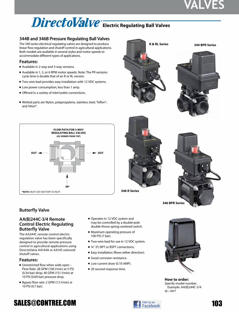
VALVES
344B and 346B Pressure Regulating Ball ValvesThe 340 series electrical regulating valves are designed to produce linear flow regulation and shutoff control in agricultural applications.Both models are available in several styles and motor speeds to accommodate different types of applications.
Features:n Available in 2-way and 3-way versions.
n Available in 1, 3, or 6 RPM motor speeds. Note: The PR versions cycle time is double that of an R or RL version.
n Two-wire lead provides easy installation with 12 VDC systems.
n Low power consumption, less than 1 amp.
n Offered in a variety of inlet/outlet connections. See pages 102–104 for additional information and options.
n Wetted parts are Nylon, polypropylene, stainless steel, Teflon®, and Viton®.
n See pages 66–68 for additional information on B style motors.
346 R Series
R & RL Series
How to order:Specify model number.
Example: AA(B)244C-3/4(B) = BSPT
AA(B)244C-3/4 Remote Control Electric Regulating Butterfly ValveThe AA244C remote control electric regulation valve has been specifically designed to provide remote pressure control in agricultural applications using DirectoValve AA144A or AA145 solenoid shutoff valves.
Features:n Unrestricted flow when wide open –
Flow Rate: 28 GPM (106 l/min) at 5 PSI (0.34 bar) drop, 40 GPM (151 l/min) at 10 PSI (0.69 bar) pressure drop.
n Bypass flow rate: 2 GPM (7.5 l/min) @ 10 PSI (0.7 bar).
n Operates in 12 VDC system and may be controlled by a double-pole double-throw spring-centered switch.
n Maximum operating pressure of 100 PSI (7 bar).
n Two-wire lead for use in 12 VDC system.
n 3/49 (F) NPT or BSPT connections.
n Easy installation (flows either direction).
n Good corrosion resistance.
n Low current draw (0.10 AMP).
n 20 second response time.
VALVES AND MANIFOLDS
Electric Regulating Ball Valves
FLOW PATH FOR 3-WAY REGULATING BALL VALVES
(AS VIEWED FROM TOP)
OUTOUT
IN*
*NOTE: MUST USE SIDE PORT AS INLET.
Butterfly Valve
344 BPR Series
346 BPR Series

VALVES
104 800-433-357972
344B shutoff ball valves are available with E or EC series motors and with cable or DIN electrical connections. See pages 66–67 for more information on DirectoValve motors.
Features:n 22 RPM, 0.7 second shutoff fully open to close.
n Flexible inlet/outlets provide quick simple plumbing for a single valve. See page 73 for more information.
n Available in 2-way or 3-way versions. 2-way valves allow complete shutoff while the 3-way valves divert flow to a bypass line when boom controls are shut off.
n Stainless steel stem with optional polypropylene or stainless steel ball.
n Maximum pressure rating is 300 PSI (20 bar).
n The flow rate for the 344BEC 2-way valve is 32 GPM (121 l/min) flow rate with a 5 PSI (0.34 bar) pressure drop, 45 GPM (170 l/min) at a 10 PSI (0.69 bar) pressure drop.
n The flow rate for the 344BEC 3-way valve is 24 GPM (91 l/min) with a 5 PSI (0.34 bar) pressure drop, 34 GPM (129 l/min) at a 10 PSI (0.69 bar) pressure drop.
n Wetted parts are Nylon, Teflon®, polypropylene, stainless steel and Viton®.
344BEC-33-C 3-Way Valve(rear view)
(front view)
344BEC-24-C 2-Way Valve(rear view)
(front view)
344 Series Electric Shutoff Valves
VALVES AND MANIFOLDS
FLOW PATH FOR 344B 3-WAY SHUTOFF BALL VALVES
(AS VIEWED FROM TOP)
*NOTE: MUST USE SIDE PORT AS INLET.
SWITCH IN “ON” POSITION
OUT OUT
IN*
SWITCH IN “OFF” POSITION
IN*

VALVES
AA145H
AA144PAA(B)144P-*
AA(B)144A-*
Spray Lines
Continuous Bypass
AA144P-, AA144A-, AA145H-, DirectoValve Control Valvesn Direct acting; large internal flow
chamber without pilot hole reduces chance of clogging.
n Stainless steel wetted parts provide additional corrosion resistance.
n Operate on 12 VDC system.
n Maximum pressure of 100 PSI (7 bar).
n Encapsulated solenoid coil can be changed without removing valve from system.
n EPDM diaphragms and seat washers, Viton® optional.
n Continuous flow through bypass connection, with flow to spray line controlled by valve “on-off” action.
Inlet
AA144A-1 AA144A Valve for Pressures up to 100 PSI (7 bar)n Flow Rate: 10 GPM (38 l/min) at 5 PSI
(0.34 bar) pressure drop, 14 GPM (53 l/min) at 10 PSI (0.69 bar) pressure drop.
n Can be ganged with other 144A DirectoValve control valves.
n 2.5 amp current draw.
n Polypropylene body for chemical resistance.
n Fabric reinforced diaphragms.
n Also available as 2- or 3-unit assembly.
How to order:To order, specify AA144A- then “1”, “2” or “3” to indicate number of units.
Example: AA(B)144A-3
AA144A-3(Three Unit)
AA144P-3(Three Unit)
AA144P DirectoValve Control Valvesn Flow Rate: 10 GPM (38 l/min) at 5 PSI
(0.34 bar) pressure drop, 14 GPM (53 l/min) at 10 PSI (0.69 bar) pressure drop.
n 2.5 amp current draw.
n Polypropylene body for chemical resistance.
n Fabric reinforced Viton diaphragms and seat washers.
n No stroke adjustment required.
n Corrosion resistant, 430SS solenoid grade armature and armature stop.
n Encapsulated coil and magnetic circuit.
How to order:To order, specify AA144P- then “1”, “2” or “3” to indicate number of units.
Example: AA(B)144P-3
AA145H Control Valvesn Flow Rate: 15 GPM (57 l/min) at 5 PSI
(0.34 bar) pressure drop, 21 GPM (79 l/min) at 10 PSI (0.69 bar) pressure drop.
n Can be ganged with other 145H DirectoValve control valves.
n 2.9 amp current draw.
n Fiberglass reinforced Nylon body.
How to order: Specify part number.
Example: AA145H-1
2-Way Electrically Operated Solenoid Valves
VALVES AND MANIFOLDS
mOdEl numbEr inlEt SizE OutlEt SizE currEnt drAW
3/49 1/29 2.5 amp
mOdEl numbEr inlEt SizE OutlEt SizE currEnt drAW
3/49 1/29 2.5 amp
mOdEl numbEr inlEt SizE OutlEt SizE currEnt drAW
AA145H-1 19 19 2.9 amp
(B) = BSPT
(B) = BSPT

VALVES
106 800-433-3579107
AA(B)144P-1-3 1
AA(B)144P-2-3 2
AA(B)144P-3-3 3
AA(B)144A-1-3 1
AA(B)144A-2-3 2
AA(B)144A-3-3 3
AA144P-3-3(Three Unit)
AA144A-3-3(Three Unit)
Inlet
Continuous Bypass
Outlet 1 (to spray line)
Outlet 2 (regulated return flow to tank)
AA144A-1-3
(B) = BSPT
AA144A-1-3 DirectoValve Control ValvesThe three-way solenoid-operated DirectoValve control valve bypasses boom flow to maintain constant spraying pressure when one or more boom sections are shut off. To maintain pressure with a 23520 Throttling Valve, Outlet 2 must be throttled to match the total capacity of the nozzles on that boom section. n For pressures to 65 PSI (4.5 bar).
n Flow Rate: 8 GPM (30 l/min) at 5 PSI (0.34 bar) pressure drop, 11 GPM (42 l/min) at 10 PSI (0.69 bar) pressure drop
n 2.5 amp current draw.
n Encapsulated 12 VDC coil can be easily changed without removing valve from line.
n Polypropylene body for chemical resistance.
n Stainless steel internal metal parts.
n Chemical resistant EPDM diaphragms and seat washers.
How to order:As with the 144A DirectoValve, the 144A-1-3 can be supplied as a 2-unit and 3-unit assembly. When ordering, specify 144A-2-3 or 144A-3-3.Note: 23520 Throttling Valve not included. See page 111 for more information.
AA144P-1-3 DirectoValve Control ValvesThe 144P-1-3 three-way solenoid-operated DirectoValve control valve was specifically designed to provide bypass control in spraying applications. When used with part number 23520-PP throttling valve or a 4916 metering orifice plate in the bypass line, it can provide for a constant pressure spray system. n For pressure to 65 PSI (4.5 bar).
n Flow Rate: 8 GPM (30 l/min) at 5 PSI (0.34 bar) pressure drop, 11 GPM (42 l/min) at 10 PSI (0.69 bar) pressure drop.
n Fabric-reinforced Viton® diaphragms.
n Nylon encapsulated 12 VDC coil with 1⁄49 Quick Connect terminals.
n Power requirement 2.5 amp.
n Glass-filled polypropylene (black) valve body.
n Internal metal parts are stainless steel.
n No stroke adjustment needed.
n Corrosion resistant, 430SS solenoid grade armature and armature stop.
How to order: Specify part number.Example: AA(B)144P-1-3
Note: 23520 Throttling Valve not included. See page 111 for more information.
TeeJet® AA144F-1-3 DirectoValve Solenoid Valve for Foam MarkersThe 144F-1-3 three-way operated DirectoValve was designed for use with foam markers. With electrical power off, flow to Outlet 1 is stopped and liquid flows to Outlet 2. With electrical power on, flow to Outlet 2 is stopped and liquid flows to Outlet 1.
Features:n Operating pressure range
of 0–50 PSI (0–3.5 bar).
n Flow Rate: 8 GPM (30 l/min) at 5 PSI (0.34 bar) pressure drop, 11 GPM (42 l/min) at 10 PSI (0.69 bar) pressure drop.
n Nylon encapsulated 12 VDC coil with 1⁄49 Quick Connect terminals.
n Glass filled polypropylene (black) valve body.
n Internal metal parts are made of brass, fasteners are made of stainless steel, other metal parts are zinc-plated.
n Chemical resistant EPDM rubber seat washer and diaphragm.
How to order: AA144F-1-3
AA144P-1-3
AA144F-1-3
3-Way Electrically Operated Solenoid Valves
VALVES AND MANIFOLDS
Solenoid Foam Marker Valves
MOdEl NuMbEr NuMbEr OF uNitS iN ASSEMbly
SPrAy liNE cONNEctiON
cONtiNuOuS FlOW iNlEt byPASS cONNEctiON
1/29 3/49
1/29 3/49
1/29 3/49
1/29 3/49
1/29 3/49
1/29 3/49

VALVES
(B)23120-*-PP
(B)23120A-*-PP
(B)23120-*-PP-60
(B)23120-*-PP-60-VI
(B)6815-*-50
(B)6815-*-300
(B)6815-*-700
AA(B)110-*-300
AA(B)110-*-700
AA(B)110-1
AA(B)110-1-1/4
AA(B)110-1-1/2
8460-*-50
8460-*
*Specify pipe size.
n Flow rate to 56 GPM (212 l/min) for 1/29 and 70 GPM (265 l/min) for 3/49.
n 8460-*-50 uses stainless steel springs while 8460-* uses steel springs—responsive to the pressure range of each valve.
n Extra large valve passages to handle full flow from supply line.
n Positive locknut to hold adjustment screw firmly in place. Not affected by jarring and vibration.
How to order:Specify valve number.
Example: 8460-1/2-50
Model 6815
Model 23120
*Specify pipe size. (B) = BSPT
*Specify pipe size. (B) = BSPT
Model 110-1, 110-1-1/4
and 110-1-1/2
Model 8460
Model 110-1/4 and 110-3/8
Model 110n Removable bonnet for servicing unit
without removing valve from line.
How to order:Specify valve number.
Example: AA(B)110-1/4-300
Model 6815n Other models for high pres sures
up to 1,200 PSI (82 bar) are also available.
n Brass also available with hardened stainless steel seat.
How to order:Specify valve number.
Example: (B)6815-1/2-50
Model 23120n 302 stainless steel spring and EPDM O-ring.
n Excellent chemical resistance.
n 1/49 port for pressure gauge pipe plug included.
Model 23120An Same as 23120 but with 316SS
spring and Viton® O-ring.
How to order:Specify valve number.
Example: (B)23120-1/2-PP
Piston-Type Pressure Relief/Regulating ValvesBypasses excess liquid. Adjustable to maintain control of line pressure at any pressure within the valve’s operating range. Selected pressure setting firmly held in place by locknut. Extra large valve passages to handle large flows.
Model 8460 Diaphragm-Type Pressure Relief/Regulating Valves
*Specify pipe size. (B) = BSPT
VALVES AND MANIFOLDS
Manual Pressure Relief/Regulating Valves
ValVe nuMbeR inlet & PiPe connections MateRial PRessuRe Range
1/29 or 3/49 Polypropylene 150 PSI (10 bar)
1/29 or 3/49 Polypropylene 150 PSI (10 bar)
1/29 or 3/49 Polypropylene 60 PSI (4 bar)
1/29 or 3/49 Polypropylene/Viton® 60 PSI (4 bar)
ValVe nuMbeR inlet & PiPe connections MateRial PRessuRe Range
1/29 or 3/49 Brass or Aluminum 50 PSI (3.5 bar)
1/29 or 3/49 Brass or Aluminum 300 PSI (20 bar)
1/29 or 3/49 Brass or Aluminum 700 PSI (48 bar)
ValVe nuMbeR inlet & PiPe connections MateRial PRessuRe Range
1/49 or 3/89 Brass 300 PSI (20 bar)
1/49 or 3/89 Brass 700 PSI (48 bar)
19 Brass, Aluminum or Ductile Iron 150 PSI (10 bar)
11/49 Brass, Aluminum or Ductile Iron 150 PSI (10 bar)
11/29 Brass, Aluminum or Ductile Iron 150 PSI (10 bar)
ValVe nuMbeR inlet & PiPe connections
MateRialPRessuRe Range
inlet body bonnet
1/29 or 3/49 Nylon Aluminum 50 PSI (3.5 bar)
1/29 or 3/49 Nylon Aluminum 300 PSI (20 bar)

VALVES
108 800-433-3579111
AA17Y
AA17L
Model AA17
“A” Index Setting
Side connection for bypass and pressure relief valve is interchangeable with spray gun connection.
1/49 NPT Pressure Gauge Port
For Selective Control of Three-Section Boom Sprayers at Pressures up to 300 PSI (20 bar).n Use to open any of three boom section
lines in any desired combination.
n Raise lever to open, lower lever to close the valve without changing the indexed position.
n Aluminum construction with stainless steel and plastic internal parts for maximum corrosion resistance.
How to order: Example: AA17Y
Molded-in Gauge Port
1/29 Boom Connection
3/49 Inlet Connections
Model 6Bn Molded of corrosion resistant materials; all
wetted parts are polypropylene, stainless steel and polyethylene.
n Maximum pressure of 150 PSI (10 bar).
n Flow Rate: 12 GPM (47 l/min) at 5 PSI (0.34 bar) pressure drop, 17 GPM (64 l/min) at 10 PSI (0.69 bar) pressure drop.
n Molded-in mounting flange and 1/49 NPT gauge port.
n Valves can be ganged together using hex nipple for multiple boom control.
n Easily repaired without removing valve from spray line.
How to order: Example: AA(B)6B(B) = BSPT
Type 12795n Pressures to 150 PSI (10 bar).
n Available in brass, aluminum or ductile iron.
n Choice of 19, 11/49 or 11/29 NPT connections.
n Flow rate at 40 PSI (3 bar) is 116 GPM (440 l/min) for 19 and 11/49 sizes and 172 GPM (651 l/min) for 11/29 size.
How to order: Example: 12795-1
Type 23520n Polypropylene con struction for
excellent chemical resistance.
n Pressures to 150 PSI (10 bar).
n 1/29 and 3/49 NPT or BSPT connections.
n 10 PSI (0.6 bar) pressure drop at 6 GPM (37.8 l/min) flow rate for 1/29; 18 GPM (69 l/min) for 3/49 size.
How to order: Example: (B)23520-1/2-PP(B) = BSPT
For regulating flow in systems equipped with centrifugal pumps where sensitive regulation is required or to control flow in jet agitator return lines. Locknut holds pressure setting firmly in place.
Throttling Valves
Control Valves
Manual Control Valve
VALVES AND MANIFOLDS
Type 12690n Pressures to 125 PSI (9 bar).
n Constructed of Nylon, Celcon®, aluminum, steel and stainless steel.
n Choice of 1/29 or 3/49 NPT connections.
n Maximum flow rate at 100 PSI (7 bar) is 56 GPM (212 l/min) for 1/29 size and 82 GPM (310 l/min) for 3/49 size.
How to order: Example: 12690-1/2-NYB
Model nuMber MATeriAl MAxiMuM pressure inleT (3) booM
ouTleTsACCessory
ouTleT
Aluminum, Polymer, SS 300 PSI (20 bar) 19 NPT 3/49 (F) 3/49 (F)
Aluminum, Polymer, SS 300 PSI (20 bar) 3/49 NPT 3/49 (F) 3/49 (F)

VALVES
[email protected] 207207
Part numberFGHT (inlet) x
MGHTType Description Max. PSI
LA5 ¾" X ¾" 1-Way Cycolac body and ball with Buna-N
seals suitable for outdoor use
75
LA24 ¾" X (2) ¾" 2-Way 75
Part number MGHT (inlet) x MGHT Description Max. PSI
3320-0065 1⁄2" X 1⁄2"" Polypropylene 3
Part number MGHT (inlet) x MGHT Description
3305-0112 1⁄2" X 1⁄2"" Polypropylene
Part number Size Max. PSI* MaterialO-ring
Material15-14 ¼" X ¼" 25 Polypropylene EPDM
nPT Part # BSP Part # Size Mounting Inserts Max PSI9951-2050N 9951-2050B 1⁄2" None 2329951-2075N 9951-2075B 3⁄4" None 2329951-2100N 9951-2100B 1" None 2329951-2125N 9951-2125B 1 1⁄4" 8 mm 1459951-2150N 9951-2150B 1 1⁄2" 8 mm 1459951-2200N 9951-2200B 2" 8 mm 145
nPT Part # BSP Part # Size Mounting Inserts Max PSI9951-3050N 9951-3050B 1⁄2" None 2329951-3075N 9951-3075B 3⁄4" None 2329951-3100N 9951-3100B 1" None 2329951-3125N 9951-3125B 1 1⁄4" 8 mm 1459951-3150N 9951-3150B 1 1⁄2" 8 mm 1459951-3200N 9951-3200B 2" 8 mm 145
• Fiberglass-reinforced polypropylene body for strength and chemical resistance• Teflon seats for smooth operation and proper sealing characteristics• EPDM O-rings to handle most fertilizers and chemicals• Max. operating pressure for sizes up to 11⁄4" – 232 PSI. For 11⁄2" and 2" – 145 PSI.
Single Union Ball Valves - 3 Way
Garden Hose Shut-Off Valve
Check Valves
Shut-Off Valves
Polypropylene Ball Valve
*Max psi for liquids compatible with polypropylene and EPDM.

VALVES
110 800-433-3579206
Part number Size Handle Type Max. PSI. Max. Temp90FFB18 1⁄8" FNPT X 1⁄8" FNPT Butterfl y 300 212° F90FFB14 1⁄4" FNPT X 1⁄4" FNPT Butterfl y 300 212° F90FMB14 1⁄4" FNPT X 1⁄4" MNPT Butterfl y 300 212° F90FFB38 3⁄8" FNPT X 3⁄8" FNPT Butterfl y 300 212° F90FMB38 3⁄8" FNPT X 3⁄8" MNPT Butterfl y 300 212° F90FFB12 1⁄2" FNPT X 1⁄2" FNPT Butterfl y 300 212° F90FMB12 1⁄2" FNPT X 1⁄2" MNPT Butterfl y 300 212° F90FFL18 1⁄8" FNPT X 1⁄8" FNPT Lever 300 212° F90FFL14 1⁄4" FNPT X 1⁄4" FNPT Lever 300 212° F90FML14 1⁄4" FNPT X 1⁄4" MNPT Lever 300 212° F90FFL38 3⁄8" FNPT X 3⁄8" FNPT Lever 300 212° F90FML38 3⁄8" FNPT X 3⁄8" MNPT Lever 300 212° F90FFL12 1⁄2" FNPT X 1⁄2" FNPT Lever 300 212° F90FML12 1⁄2" FNPT X 1⁄2" MNPT Lever 300 212° F90-HBF Replacement nylon butterfl y handleRI167 Replacement nylon lever handle
Series 90 – Plated Brass Ball Valve
10-32 threaded mounting holes. Tefl on seals and o-rings.
Part number Material Size Max. PSI Max. Temp.171N-14 Brass 1⁄4" FNPT 600 320° F171N-38 Brass 3⁄8" FNPT 600 320° F171N-12 Brass 1⁄2" FNPT 600 320° F171N-34 Brass 3⁄4" FNPT 600 320° F171N-100 Brass 1" FNPT 600 320° F171N-114 Brass 11⁄4" FNPT 600 320° F171N-112 Brass 11⁄2" FNPT 600 320° F171N-200 Brass 2" FNPT 600 320° F
78-14 316 Stainless Steel 1⁄4" FNPT 1000 320° F78-38 316 Stainless Steel 3⁄8" FNPT 1000 320° F78-12 316 Stainless Steel 1⁄2" FNPT 1000 320° F78-34 316 Stainless Steel 3⁄4" FNPT 1000 320° F78-100 316 Stainless Steel 1" FNPT 1000 320° F78-114 316 Stainless Steel 11⁄4" FNPT 1000 320° F78-112 316 Stainless Steel 11⁄2" FNPT 1000 320° F78-200 316 Stainless Steel 2" FNPT 1000 320° F78-300 316 Stainless Steel 3" FNPT 1000 320° F
Full Port Brass and 316 Stainless Steel Ball Valves
Ball Valves
RAVEN, TEE-JET, HYPRO, BANJO VALVES...We carry them all.
If you don’t see the part listed that you need just contact us and we can order it for you. Contact one of our sales team members
1-800-433-3579 or [email protected]

Manifolds
1” Banjo Electric Flanged Valve Assemblies
PART NO DESCRIPTION MAX PSI
MEV102CF 1” Manifold Valve Assembly 2” Inlet Flanges, 1” Outlet Flanges 150
MEV103CF 1” Manifold Valve Assembly 2” Inlet Flanges, 1” Outlet Flanges 150
MEV103MB 1” Manifold Valve Assembly 2” Inlet Flanges, 1” Outlet Flanges w/ Brackets 150
MEV104CF 1” Manifold Valve Assembly 2” Inlet Flanges, 1” Outlet Flanges 150
MEV105CF 1” Manifold Valve Assembly 2” Inlet Flanges, 1” Outlet Flanges 150
M200100TEEB 2” x 1” Standard Port Flanged Tee w/ Bracket 150
1”- 3” Banjo Electric Flanged Valves
PART NO DESCRIPTION MAX PSI
PIPE SIZE
BALL PORT
MEV100CF 1” Full Port Electric Valve 150 1” 1”MEV200CF 2” Standard Port Electric Valve 150 2” 1½”MEV220CF 2” Full Port Electric Valve 150 2” 2”MEV300CF 3” Full Port Electric Valve 100 3” 3”
4 Second Response Time (Regulating)
¾ to 1¼ Second Response Time
•1”-2”has316stainlesssteelball&stem.•3”haspolyball&stainlesssteelstem.•Fiberglassreinforced polypropylene.•GlassreinforcedPTFEseats.•FKM(vitontype)orEPDMO-rings.•12-voltDCoperated.•150P.S.I.maxpressure.•Internallyfused/automaticreset.•Open/closedindicator.
PART NO DESCRIPTION MAX SPIKEMPRV100-050 1” Pressure Spike Valve 50 PSIMPRV100-075 1” Pressure Spike Valve 75 PSIMPRV100-100 1” Pressure Spike Valve 100 PSIMPRV100-125 1” Pressure Spike Valve 125 PSIMPRV100-150 1” Pressure Spike Valve 150 PSI
Pressure Spike Valves
PART NO DESCRIPTION MAX PSI
PIPE SIZE
BALL PORT
MEVR100CF 1” Full Port Electric Valve 150 1” 1”MEVR200CF 2” Standard Port Electric Valve 150 2” 1½”MEVR220CF 2” Full Port Electric Valve 150 2” 2”
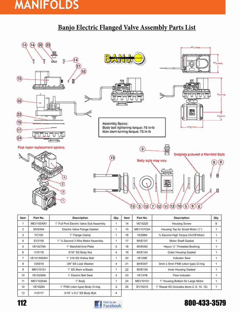
Manifolds
112 800-433-3579
Item Part No. Description Qty. Item Part No. Description Qty.
1 MEV100XR1 1” Full Port Electric Valve Sub Assembly 1 14 VE15220 Housing Screw 6
2 MVE004 Electric Valve Flange Gasket 1 15 MEV10102A Housing Top for Small Motor (1”) 1
3 FC100 1” Flange Clamp 1 16 VE4984 ¾ Second High Torque On/Off Motor 1
4 EV3100 1” ¾ Second 3 Wire Motor Assembly 1 17 MVE107 Motor Shaft Gasket 1
5 VE10278A 1” Manifold End Plate 2 18 MVE002 Heyco ¼” Threaded Bushing 1
6 V10119 5/16” SS Body Nut 4 19 MVE104 Outer Housing Gasket 1
7 VE10155SSH 1” 316 SS Hollow Ball 1 20 VE109E Indicator Seal 1
8 V20018 3/8” SS Lock Washer 4 21 MVE007 3mm x 5mm FKM (viton type) O-ring 1
9 MEV10151 1” SS Stem w/Seals 1 22 MVE106 Inner Housing Gasket 1
10 VE10258A 1” Electric Ball Seat 2 23 VE107B Flow Indicator 1
11 MEV10254A 1” Body 1 24 MEV10101 1” Housing Bottom for Large Motor 1
12 VE10264 1” FKM (viton type) Body O-ring 2 25 EV10210 1” Repair Kit (Includes items 2, 9, 10, 12) 1
13 V10117 5/16” x 3½” SS Body Bolt 4
Banjo Electric Flanged Valve Assembly Parts List

Manifolds
88
453BEC-24-C Manifold(rear view)
451BEC-2F-C Valve(rear view)
(front view)
(front view)
450BEC manifolds are available with E or EC series motors with cable or DIN electrical connections. See page 66 for more information on DirectoValve motors.
Features:n 22 RPM, 0.7 second shutoff fully open to close.
n Available in 2-way and Flow Back versions. Pressure regulating valves can be incorporated.
n Flexible inlet/outlet connections allow for quick, simple plumbing for as many valves as needed for your sprayer.
n Stainless steel stem with optional polypropylene or stainless steel ball.
n Maximum pressure rating of 200 PSI (14 bar).
n The flow rate for the 450BEC 2-way valve is 32 GPM (121 l/min) with 5 PSI (0.34 bar) pressure drop, 45 GPM (170 l/min) with 10 PSI (0.69 bar) pressure drop.
n Wetted parts are Nylon, Teflon®, polypropylene and Viton®.
450 Series Shutoff Manifold
VALVES AND MANIFOLDS
TeeJet 450BEC SeriesDirectoValve® Electric Shut-Off Ball Valve Manifold

Manifolds
114 800-433-3579
Flanged Bolted Ball Valves- 4 and 6 Bolt
Flanged 2” Standard Port “Stubby” Valve
PART NO DESCRIPTION MAX PSI
PIPE SIZE
BALL PORT
MV100CF 1” Flange Ball Valve 150 1” 1”MV200CF 2” Flange Ball Valve 150 2” 1½”MV220CF 2” Full Port Flange Ball Valve 150 2” 2”MV225CF 2” Full Port Flange 5 Way Valve 150 2” 2”
MV300 3” Standard Flange Ball Valve 100 3” 2½”MV300CF 3” Full Port Flange Ball Valve 100 3” 3”
PART NO DESCRIPTION MAX PSI
PIPE SIZE
BALL PORT
MVS220FP 2” FP Flange x 2” Female NPT 100 2” 2”MVSF220FP 2” FP Flange x 2” Male Adapter 100 2” 2”MVS220CF 2” FP Flange x 2” FP Flange 100 2” 2”
MVSMT220FP 2” FP Flange x 2” Male NPT 100 2” 2”
PART NO DESCRIPTION MAX PSI
PIPE SIZE
BALL PORT
VSMT200CF 2” Flange x 2” Male NPT 100 2” 1½”VSF200CF 2” Flange x 2” Male Adapter 100 2” 1½”
PART NO DESCRIPTION MAX PSI
PIPE SIZE
BALL PORT
MVS220HSFP 2” FP Flange x 2” FP Flange w/ SS Ball, Stem & Handle 100 2” 2”MVSF220HSFP 2” FP Flange x 2” Male NPT w/ SS Ball, Stem & Handle 100 2” 2”
MVSMT220HSFP 2” FP NPT x 2” Male Flange w/ SS Ball, Stem & Handle 100 2” 2”
Flanged 2” Full Port “Stubby” Poly Body/Stainless Steel Ball & Valve
Flanged 2” Full Port “Stubby” Valve

Manifolds
PART NO DESCRIPTION MAX PSI
PIPE SIZE
BALL PORT
MVS220SS 2” FP Flange x 2” FP Flange Stainless Steel Stubby Valve 1000 2” 2”MVSF220SS 2” FP Flange x 2” Male Adapter Stainless Steel Stubby Valve 1000 2” 2”
MVSMT220SS 2” FP Male NPT x 2” FP Flange Stainless Steel Stubby Valve 1000 2” 2”
Flanged 2” Full Port “Stubby” Full Stainless Steel Valve
PART NO DESCRIPTION MAX PSI
PIPE SIZE
BALL PORT
MVSF300 3” Flange x 3” Male Adapter 100 3” 2½”MVSF300FP 3” Full Port Flange x 3” Male Adapter 100 3” 3”MVSMT300 3” Flange x 3” Male NPT 100 3” 2½”MVS300CF 3” Flange x 3” Flange 100 3” 2½”
MVS300CFFP 3” Full Port Flange x 3” Full Port Flange 100 3” 3”
Flanged 3” Standard and Full Port “Stubby” Valve
Flanged 2” Full Port “Stubby” Poly Body/Stainless Steel Ball & Valve PART NO DESCRIPTION MAX
PSIPIPE SIZE
BALL PORT
MVS220HSFP 2” FP Flange x 2” FP Flange w/ SS Ball, Stem & Handle 100 2” 2”MVSF220HSFP 2” FP Flange x 2” Male NPT w/ SS Ball, Stem & Handle 100 2” 2”
MVSMT220HSFP 2” FP NPT x 2” Male Flange w/ SS Ball, Stem & Handle 100 2” 2”
PART NO DESCRIPTION MAX PSI
PIPE SIZE
BALL PORT
HANDLE TYPE
MV300BL 3” Manifold Flanged Valve 100 3” 3” Straight
3” Flanged 6 Bolt Ball Valve
PART NO DESCRIPTION MAX PSI ACCURACYFM100 1” Full Port Female NPT Flow Meter 150 99% ~ 2-110 GPM
MFM100 1” Full Port Manifold Flow Meter 150 99% ~ 2-110 GPMMFM220 2” Full Port Manifold Flow Meter 150 99% ~ 6-300 GPMMFM300 3” Full Port Manifold Flow Meter 150 99% ~ 14-670 GPM
Flanged Flow Meters

Manifolds
116 800-433-3579
PART NO DESCRIPTION MAX PSI
PIPE SIZE
BALL PORT
HANDLE TYPE
MV100SL 1” Manifold Flanged Valve 100 1” 1” TMV200SL 2” Manifold Flanged Valve 100 2” 1½” StraightMV220SL 2” Full Port Manifold Flanged Valve 100 2” 2” Straight
MVT220SL 2” Full Port Manifold Flanged Valve 100 2” 2” T
1” & 2” 4-Bolt Bottom Load Flanged Valves
1” & 2” 4-Bolt Side Load Flanged Valves
PART NO DESCRIPTION MAX PSI
PIPE SIZE
BALL PORT
HANDLE TYPE
MV100BL 1” Manifold Flanged Valve 100 1” 1” TMV200BL 2” Manifold Flanged Valve 100 2” 1½” TMV220BL 2” Full Port Manifold Flanged Valve 100 2” 2” Straight
PART NO DESCRIPTION MAX PSI
PIPE SIZE
BALL PORT
DM200ACF 2” Flanged Male Dry-Mate 100 2” 1½”DM200DCF 2” Flanged Female Dry-Mate 100 2” 1½”
Flanged Dry-Disconnect Valves
PART NO DESCRIPTION PRESSURE AT PUMP
VOLUME GPM
OPENING SIZE
HV150 1½” MPT Poly Inductor 50 PSI 37 GPM 5⁄16”HV200 2” MPT Poly Inductor 50 PSI 49 GPM 7⁄16”
MHV200 2” Manifold Poly Inductor with 1½” Port 50 PSI 37 GPM 5⁄16”MHV220A 2” FP Manifold Poly Inductor 50 PSI 49 GPM 9⁄16”
Flanged Poly Inductors
PART NO DESCRIPTIONMIS220 2” Full Port Flange x Flange-AssembledMIS300 3” Flange x Flange-Assembled
Manifold Flanged Poly Inductors Assemblies

Manifolds
www.banjocorp.com [email protected] MANIFOLD SYSTEMS MANIFOLD SYSTEMSM
ANIFO
LD S
YSTEM
S
FEATURES• Direct replacement for standard 90° flanged couplings.
SWEEPSPART NO DESCRIPTION QTY PRICE
M100SWP90 1" Flange x Flange Sweep 1 $12.75M100BRBSWP90 1" Flange x Hose Shank Sweep 1 $13.88M100125BRBSWP90 1" Flange x 1¼" Hose Shank Sweep 1 $15.70M200SWP90 2" Flange x Flange Sweep 1 $14.49M220ASWP90 2" Full Port Flange x Male Adapter Sweep 1 $14.73M220BRBSWP90 2" Full Port Flange x Hose Shank Sweep 1 $34.75M220MPTSWP90 2" Full Port Flange x Male NPT Thread Sweep 1 $14.73M220SWP90 2" Full Port Flange x Flange Sweep 1 $14.73M220SWP90SS 2" Full Port SS Flange x Flange Sweep 1 $112.68
M220200SWP90 2" Full Port Flange x 2" Flange Sweep 1 $15.66M300ASWP90 3" Flange x Male Adapter Sweep 1 $67.56M300BRBSWP90 3" Flange x Hose Shank Sweep 1 $67.56M300MPTSWP90 3" Flange x Male NPT Thread Sweep 1 $67.56M300SWP90 3" Flange x Flange Sweep 1 $67.56
SWEEPS w/Gauge PortPART NO DESCRIPTION QTY PRICE
M100SWPG90 1" Flange x Flange Sweep with ¼" gauge port 1 $15.88
M100BRBSWPG90 1" Full Port Flange x 1" Hose Shank Sweep w/ ¼" gauge port 1 $15.88
M300ASWPG90 3" Flange x Male Adapter Sweep w/ ¼" gauge port 1 $67.56
M300MPTSWPG90 3" Flange x Male NPT Thread Sweep w/¼" gauge port 1 $67.56
M300SWPG90 3" Flange x Flange Sweep w/ ¼" gauge port 1 $67.56
M220SWP90
M220BRBSWP90 M220MPTSWP90M220ASWP90
M300ASWPG90
M300ASWP90
M300SWP90 M300SWPG90
M300MPTSWP90
M300MPTSWPG90
Improved Flow for Max GPM!
Sweeps
M200SWP90
M220200SWP90
M220SWP90SS
M300BRBSWP90
M100SWP90 M100SWPG90 M100BRBSWP90 M100BRBSWPG90
M100125BRBSWP90 M300BRBSWP90
NEW! NEW! NEW! NEW!
NEW! NEW!
PART NO DESCRIPTION PART NO DESCRIPTION
M100BRBSWP90 1” Flange x Hose Shank Sweep M300ASWP90 3” Flange x Male Adapter Sweep
M100125BRBSWP90 1” Flange x 1¼” Hose Shank Sweep M300BRBSWP90 3” Flange x Hose Shank Sweep
M200SWP90 2” Flange x Flange Sweep M300MPTSWP90 3” Flange x Male NPT Thread Sweep
M220ASWP90 2” Full Port Flange x Male Adapter Sweep M300SWP90 3” Flange x Flange Sweep
M220BRBSWP90 2” Full Port Flange x Hose Shank Sweep M100SWPG90 1” Flange x Flange Sweep with ¼” gauge port
M220MPTSWP90 2” Full Port Flange x Male NPT Thread Sweep M100BRBSWPG90 1” Full Port Flange x 1” Hose Shank Sweep with ¼” gauge port
M220SWP90 2” Full Port Flange x Flange Sweep M300ASWPG90 3” Flange x Male Adapter Sweep with ¼” gauge port
M220SWP90SS 2” Full Port SS Flange x Flange Sweep M300MPTSWPG90 3” Flange x Male NPT Thread Sweep with ¼” gauge port
M220200SWP90 2” Full Port Flange x 2” Flange Sweep M300SWPG90 3” Flange x Flange Sweep with ¼” gauge port
Flanged Sweeps Poly & Stainless Steel

Manifolds
118 800-433-3579
PART NO DESCRIPTIONM100CPG 1” x 1” Flange x 2¼” LongM200CPG 2” x 2” Flange x 4½” LongM220CPG 2” x 2” Full Port Flange x 2 31⁄ 32”
M220CPG6 2” x 2” Full Port Flange x 6” LongM300CPG 3” x 3” Full Port Flange x 4” Long
M300CPG7 3” x 3” Full Port Flange x 7” Long
PART NO DESCRIPTIONM100CPG45 1” x 1” 45° FlangeM200CPG45 2” x 2” 45° FlangeM220CPG45 2” x 2” 45° Full Port FlangeM300CPG45 3” x 3” 45° Full Port Flange
PART NO DESCRIPTIONM100CPG90 1” x 1” 90° FlangeM200CPG90 2” x 2” 90° Flange
M200CPG90SH 2” x 2” 90° Short FlangeM220CPG90 2” x 2” 90° Full Port FlangeM300CPG90 3” x 3” 90° Full Port Flange
PART NO DESCRIPTIONM200100CPG 2” Port x 1” Reducer FlangeM220100CPG 2” Full Port x 1” Reducer FlangeM220200CPG 2” Full Port x 2” Reducer FlangeM300200CPG 3” x 2” Port Reducer FlangeM300220CPG 3” x 2” Full Port Reducer Flange
PART NO DESCRIPTIONM100TEE 1” Flanged TeeM101TEE 1” Flanged Tee - Long
M200100TEE 2” Port x 1” Flanged TeeM200TEE 2” Port Flanged Tee
M200100TEEB 2” x 1” Port Flanged Tee w/Mounting BracketM220100TEE 2” Full Port Flanged Tee x 1” Flanged TeeM220200TEE 2” Full Port Flanged Tee x 2” Flanged Tee
M220TEE 2” Full Port Flanged TeeM300TEE 3” Flanged TeeM100CR 1” Flanged CrossM200CR 2” Flanged CrossM220CR 2” Full Port Flanged Cross
M220CRSS 2” Full Port SS Flanged CrossM300CR 3” Flanged Cross
Flanged Poly Couplers
Flanged 45° Poly Couplers
Flanged 90° Poly Couplers
Flanged Poly Reducers
Flanged Poly & Stainless Steel Tees & Crosses

Manifolds
PART NO DESCRIPTIONM220Y45 2” Full Port 45° Y Flange
M220YG45 2” Full Port 45° Y Flange w/ ¾” gauge portM300Y45 3” Full Port 45° Y Flange
M300YG45 3” Full Port 45° Y Flange w/ ¾” gauge port
PART NO DESCRIPTIONUB100 100 Series Mounting U Bolt - SSUB202 200 Series Mounting U Bolt - SSUB220 220 Series Mounting U Bolt - SS
PART NO DESCRIPTIONM100050FPT 1” Flange x ½” Pipe ThreadM100075FPT 1” Flange x ¾” Pipe Thread
M100FPT 1” Flange x 1” Pipe ThreadM200FPT 2” Flange x 2” Pipe ThreadM220FPT 2” Full Port Flange x 2” Pipe ThreadM300FPT 3” Flange x 3” Pipe Thread
PART NO DESCRIPTIONM100075MPT 1” Flange x ¾” Male Thread
M100MPT 1” Flange x 1” Male ThreadM100125MPT 1” Flange x 1¼” Male ThreadM200125MPT 2” Flange x 1¼” Male ThreadM200150MPT 2” Flange x 1½” Male Thread
M200MPT 2” Flange x 2” Male ThreadM220MPT 2” Full Port Flange x 2” Male ThreadM300MPT 3” Flange x 3” Male Thread
PART NO DESCRIPTIONM220D 2” Full Port Flange x 2” Female CouplerM303D 3” Full Flange x 3” Female Coupler w/3 ArmsM100A 1” Flange x 1” Male AdapterM200A 2” Flange x 2” Male AdapterM220A 2” Full Port Flange x 2” Male AdapterM300A 3” Full Port Flange x 3” Male Adapter
Flanged 45° Poly Couplers
Stainless Steel U-Bolts
Poly Flange to Female Pipe Thread
Poly Flange to Quick Disconnect
Poly Flange to Male Pipe Thread

Manifolds
120 800-433-3579
PART NO DESCRIPTIONM100075BRB 1” Flange x ¾” Hose Barb
M100BRB 1” Flange x 1” Hose BarbM100125BRB 1” Flange x 1¼” Hose BarbM200100BRB 2” Flange x 1” Hose BarbM200125BRB 2” Flange x 1¼” Hose BarbM200150BRB 2” Flange x 1½” Hose Barb
M200BRB 2” Flange x 2” Hose BarbM220100BRB 2” Full Port Flange x 1” Hose BarbM220125BRB 2” Full Port Flange x 1¼” Hose BarbM220150BRB 2” Full Port Flange x 1½” Hose Barb
M220BRB 2” Full Port Flange x 2” Hose BarbM300220BRB 3” Flange x 2” Hose Barb
M300BRB 3” Flange x 3” Hose BarbM100075BRB90 1” Flange x ¾” 90° Hose Barb Elbow
M100BRB90 1” Flange x 1” 90° Hose Barb ElbowM100125BRB90 1” Flange x 1¼” 90° Hose Barb ElbowM100150BRB90 1” Flange x 1½” 90° Hose Barb ElbowM200100BRB90 2” Flange x 1” 90° Hose Barb ElbowM200125BRB90 2” Flange x 1¼” 90° Hose Barb ElbowM200150BRB90 2” Flange x 1½” 90° Hose Barb Elbow
M200BRB90 2” Flange x 2” 90° Hose Barb ElbowM220150BRB90 2” Full Port Flange x 1½” 90° Hose Barb Elbow
M220BRB90 2” Full Port Flange x 2” 90° Hose Barb ElbowM300220BRB90 3” Flange x 2” 90° Hose Barb Elbow
M300BRB90 3” Flange x 3” 90° Hose Barb ElbowM100BRB45 1” Flange x 1” 45° Hose Barb ElbowM200BRB45 2” Flange x 2” 45° Hose Barb ElbowM220BRB45 2” Full Port Flange x 2” 45° Hose Barb ElbowM300BRB45 3” Flange x 3” 45° Hose Barb Elbow
M200150BRB45 2” Flange x 1½” 45° Hose Barb ElbowM100100HBT 1” Flange x 1” Hose Barb TeeM100125HBT 1” Flange x 1¼” Hose Barb TeeM220200HBT 2” Full Port Flange x 2” Hose Barb TeeM300300HBT 3” Flange x 3” Hose Barb Tee
PART NO DESCRIPTIONM100MPTSS 1” Flange x 1” Male Thread
M200125MPTSS 2” Flange x 1¼” Male ThreadM200150MPTSS 2” Flange x 1½” Male Thread
M200MPTSS 2” Flange x 2” Male ThreadM220150MPTSS 2” Full Port Flange x 1½” Male Thread
M220MPTSS 2” Full Port Flange x 2” Male ThreadM300220MPTSS 3” Flange x 2” Full Port Male Thread
M300MPTSS 3” Flange x 3” Male Thread
Poly Flange to Hose Barb
Stainless Steel Flange to Male Pipe Thread

Manifolds
PART NO DESCRIPTION TORQUEFC100 100 Series Worm Screw Clamp 90-100 in/lbsFC200 200 Series Worm Screw Clamp 90-100 in/lbsFC220 220 Series Worm Screw Clamp 90-100 in/lbsFC300 300 Series Worm Screw Clamp 90-100 in/lbs
FC220B 2” Full Port Bolted Flange Clamp 150 in/lbsFC300B 3” Bolted Flange Clamp 150 in/lbs
FC220TB 2” Full Port Hi-Torque T-Bolt Flange Clamp 125 in/lbsFC300TB 3” Full Port Hi-Torque T-Bolt Flange Clamp 125 in/lbs
PART NO DESCRIPTIONM100G 1” EPDM Manifold GasketM101G* 1” EPDM Manifold Gasket with RibM100GV 100 Series FKM (viton type) Gasket
150G 1½” EPDM Gasket150GV 200 Series FKM (viton type) Gasket200G 220 Series Full Port EPDM Gasket
200GV 220 Series Full Port FKM (viton type) GasketM201G* 2” EPDM Manifold Gasket with RibM221G* 2” Full Port EPDM Manifold Gasket with Rib
300G 3” EPDM Gasket300GV 300 Series FKM (viton type) Gasket
M301G* 3” EPDM Manifold Gasket with Rib
PART NO DESCRIPTION MAX PSIMLST100-16 1” Manifold T Strainer w/16 Mesh Screen 150MLST100-30 1” Manifold T Strainer w/30 Mesh Screen 150MLST100-50 1” Manifold T Strainer w/50 Mesh Screen 150MLST100-80 1” Manifold T Strainer w/80 Mesh Screen 150
MLST100-100 1” Manifold T Strainer w/100 Mesh Screen 150MLST150-16 2” Manifold T Strainer w/16 Mesh Screen 150MLST150-30 2” Manifold T Strainer w/30 Mesh Screen 150MLST150-50 2” Manifold T Strainer w/50 Mesh Screen 150MLST150-80 2” Manifold T Strainer w/80 Mesh Screen 150
MLST150-100 2” Manifold T Strainer w/100 Mesh Screen 150
Stainless Steel Flange Clamps
Flange GasketsEDPM & FKM (Viton Type)
Flange T-Line Strainer

Manifolds
122 800-433-3579
PART NO DESCRIPTION MAX PSI
MLS100-20 1” Manifold Y Strainer w/20 Mesh Screen 150MLS100-40 1” Manifold Y Strainer w/40 Mesh Screen 150MLS100-50 1” Manifold Y Strainer w/50 Mesh Screen 150MLS100-80 1” Manifold Y Strainer w/80 Mesh Screen 150MLS200-06 2” Manifold Y Strainer w/6 Mesh Screen 150MLS200-12 2” Manifold Y Strainer w/12 Mesh Screen 150MLS200-20 2” Manifold Y Strainer w/20 Mesh Screen 150MLS200-30 2” Manifold Y Strainer w/30 Mesh Screen 150MLS200-50 2” Manifold Y Strainer w/50 Mesh Screen 150MLS200-80 2” Manifold Y Strainer w/80 Mesh Screen 150
MLS200-100 2” Manifold Y Strainer w/100 Mesh Screen 150MLS200-120 2” Manifold Y Strainer w/120 Mesh Screen 150MLS222-04 2” Full Port Manifold Y Strainer w/4 Mesh Screen 150MLS222-06 2” Full Port Manifold Y Strainer w/6 Mesh Screen 150MLS222-08 2” Full Port Manifold Y Strainer w/8 Mesh Screen 150MLS222-10 2” Full Port Manifold Y Strainer w/10 Mesh Screen 150MLS222-16 2” Full Port Manifold Y Strainer w/16 Mesh Screen 150MLS222-30 2” Full Port Manifold Y Strainer w/30 Mesh Screen 150MLS222-50 2” Full Port Manifold Y Strainer w/50 Mesh Screen 150MLS222-80 2” Full Port Manifold Y Strainer w/80 Mesh Screen 150
MLS222-100 2” Full Port Manifold Y Strainer w/100 Mesh Screen 150MLS300-04 3” Manifold Y Strainer w/4 Mesh Screen 100MLS300-08 3” Manifold Y Strainer w/8 Mesh Screen 100MLS300-12 3” Manifold Y Strainer w/12 Mesh Screen 100MLS300-20 3” Manifold Y Strainer w/20 Mesh Screen 100MLS300-50 3” Manifold Y Strainer w/50 Mesh Screen 100
Flange Y-Line Strainer
MESH SIZE RIB COLOR6 MESH WHITE
12 MESH BLACK20 MESH BEIGE30 MESH YELLOW40 MESH BROWN50 MESH RED80 MESH BLUE
100 MESH GREEN120 MESH BLACK
Size Strainer 6 Mesh 12 Mesh 16 Mesh 20 Mesh 30 Mesh 40 Mesh 50 Mesh 80 Mesh 100 Mesh 120 Mesh 150 Mesh
1” T Strainer LST116 LST130 LST150 LST180 LST1100
1½” T Strainer LST1516 LST1530 LST1550 LST1580 LST15100
1” Y Strainer LS120 LS140 LS150 LS180
2” Y Strainer LS206 LS212 LS220 LS230 LS250 LS280 LS2100 LS2120 LS2150
O-Rings/Gaskets Bowl gasket Screen O-ring
1” T Strainer LST100-G (EDPM) LST100-GV (FKM-Viton type) 13778 (2)
1½” T Strainer LST150-G (EDPM) LST150-GV (FKM-Viton type) LST034G (2)
1” Y Strainer LS100-G (EDPM) LS125G (2)
2” Y Strainer LS150-G (EDPM) LS150-GV (FKM-Viton type) LS141G (2)
In-Line Strainer Replacements Screens and Gaskets

Manifolds
PART NO DESCRIPTIONMBF100BD 1” Flange x 1” EPDM Female Thread
MBF100BDV 1” Flange x 1” FKM(viton type) Female ThreadMBF150200BD 2” Flange x 1½” EPDM Female Thread
MBF150200BDV 2” Flange x 1½” FKM (viton type) Female ThreadMBF200BD 2” Flange x 2” EPDM Female Thread
MBF200BDV 2” Flange x 2” FKM(viton type) Female ThreadMBF220BD 2” Full Port Flange x 2” EPDM Female Thread
MBF220BDV 2” Full Port Flange x 2” FKM(viton type)Female ThreadMBF300BD 3” Flange x 3” EPDM Female Thread
MBF300BDV 3” Flange x 3” FKM(viton type) Female ThreadMBF100 1” Flange x 1” EPDM Female Thread
MBF100V 1” Flange x 1” FKM (viton type) Female ThreadMBF200 2” Flange x 2” EPDM Female Thread
MBF200V 2” Flange x 2” FKM (viton type) Female ThreadMBF220 2” Full Port Flange x 2” EPDM Female Thread
MBF220V 2” Full Port Flange x 2” FKM (viton type) Female ThreadMBF300 3” Flange x 3” EPDM Female Thread
MBF300V 3” Flange x 3” FKM (viton type) Female Thread
Bolted “Bottom Drain” Flange Tank Fittings
PART NO DESCRIPTION HOLE SIZEMTF220BD 2” x 2” Full Port Manifold EPDM Flange 3¼”MTF300BD 3” x 3” Manifold EPDM Flange 4½”
MTF220 2” Manifold Poly Bulkhead EPDM Tank Fitting 3¼”MTF300 3” Manifold Poly Bulkhead EPDM Tank Fitting 4½”
“Bottom Drain” and Bulkhead Flange Tank Fittings
PART NO DESCRIPTION MAX PSIMSW220 2” Full Port Manifold Flange Swivel 75
PART NO DESCRIPTION PSI FLOWMCV100 1” Flanged Poly Check Valve 150 1”MCV200 2” Flanged Poly Check Valve 150 1½”MCV221 2” Full Port Flanged Poly Check Valve 150 2”MCV300 3” Flanged Poly Check Valve 150 3”
PART NO DESCRIPTIONM100PA 1” Flanged Pipe Adapter
M100PAC 1” Flanged Pipe Adapter CapM100PAT 1” Flanged Pipe Adapter Tee
Flanged Poly Swivel
Flanged Poly Check Valve
Boom nozzle Pipe Adapter
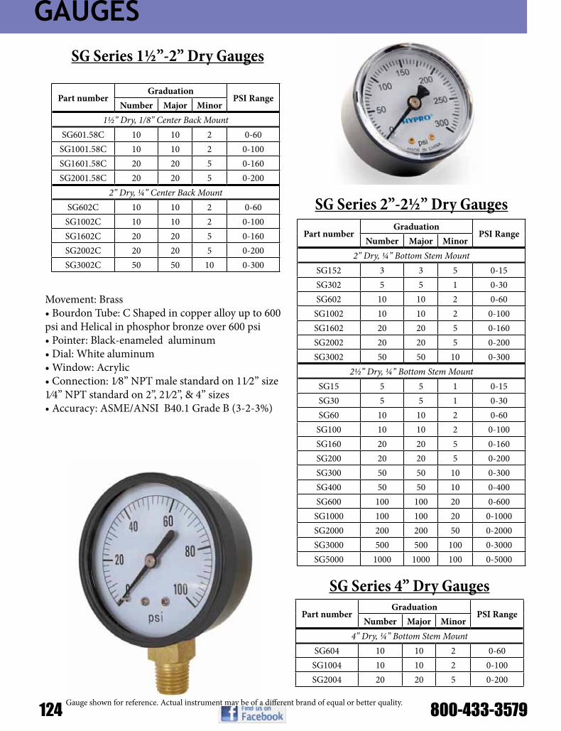
GAUGES
124 800-433-3579
Part numberGraduation
PSI RangeNumber Major Minor
1½” Dry, 1/8” Center Back MountSG601.58C 10 10 2 0-60
SG1001.58C 10 10 2 0-100SG1601.58C 20 20 5 0-160SG2001.58C 20 20 5 0-200
2” Dry, ¼” Center Back MountSG602C 10 10 2 0-60
SG1002C 10 10 2 0-100SG1602C 20 20 5 0-160SG2002C 20 20 5 0-200SG3002C 50 50 10 0-300
SG Series 1½”-2” Dry Gauges
Movement: Brass•BourdonTube:CShapedincopperalloyupto600psi and Helical in phosphor bronze over 600 psi•Pointer:Black-enameledaluminum•Dial:Whitealuminum•Window:Acrylic•Connection:1⁄8”NPTmalestandardon11⁄2”size1⁄4” NPT standard on 2”, 21⁄2”, & 4” sizes•Accuracy:ASME/ANSIB40.1GradeB(3-2-3%)
Part numberGraduation
PSI RangeNumber Major Minor
2” Dry, ¼” Bottom Stem MountSG152 3 3 5 0-15SG302 5 5 1 0-30SG602 10 10 2 0-60
SG1002 10 10 2 0-100SG1602 20 20 5 0-160SG2002 20 20 5 0-200SG3002 50 50 10 0-300
2½” Dry, ¼” Bottom Stem MountSG15 5 5 1 0-15SG30 5 5 1 0-30SG60 10 10 2 0-60
SG100 10 10 2 0-100SG160 20 20 5 0-160SG200 20 20 5 0-200SG300 50 50 10 0-300SG400 50 50 10 0-400SG600 100 100 20 0-600
SG1000 100 100 20 0-1000SG2000 200 200 50 0-2000SG3000 500 500 100 0-3000SG5000 1000 1000 100 0-5000
SG Series 2”-2½” Dry Gauges
Part numberGraduation
PSI RangeNumber Major Minor
4” Dry, ¼” Bottom Stem MountSG604 10 10 2 0-60
SG1004 10 10 2 0-100SG2004 20 20 5 0-200
SG Series 4” Dry Gauges
Gauge shown for reference. Actual instrument may be of a different brand of equal or better quality.

GAUGES
•Movement:Brass•BourdonTube:Phosphorbronze•Pointer:Black-enameledaluminum•Dial:Whitebackground•Window:Acrylic•LiquidFill:99.5%purevirginGlycerin•Connection:1⁄4”NPTBrassconnection•Accuracy:ASME/ANSIB40.1GradeB(3-2-3%)
Part numberGraduation
PSI RangeNumber Major Minor
2½” SS, Liquid Filled, Brass Internals, ¼” BSMVGG30 30 Hg 0
VGG3030 30 Hg 0-30
VGG3060 30 Hg 0-60
VGG30160 30 Hg 0-160GG30 5 5 1 0-30GG60 10 10 2 0-60
GG100 10 10 2 0-100GG160 20 20 5 0-160GG200 20 20 5 0-200GG300 50 50 10 0-300GG400 50 50 10 0-400GG600 100 100 20 0-600
GG1000 200 200 20 0-1000GG1500 300 300 50 0-1500GG2000 200 200 50 0-2000GG3000 500 500 100 0-3000GG4000 500 500 100 0-4000GG5000 1000 1000 100 0-5000GG6000 1000 1000 200 0-6000
GG10000 2000 2000 200 0-10000GG15000 3000 3000 500 0-15000
GG Series 2½” Glycerin-Filled Gauges
Part numberGraduation
PSI RangeNumber Major Minor
4” SS, Liquid Filled, Brass Internals, ¼” BSMVGG30604 30 Hg 0-60 psi
GG604 10 10 2 0-60GG1004 10 10 2 0-100
GG Series 4” Glycerin-Filled Gauges
Part numberGraduation
PSI RangeNumber Major Minor
2½” SS, Liquid Filled, Brass Internals, ¼” CBMWGG60C 10 10 2 0-60
WGG100C 10 10 2 0-100WGG160C 20 20 2 0-160WGG200C 20 20 5 0-200WGG300C 50 50 10 0-300WGG400C 50 50 10 0-400WGG600C 100 100 20 0-600
WGG1000C 100 100 20 0-1000WGG1500C 300 300 50 0-1500WGG2000C 200 200 50 0-2000WGG3000C 500 500 100 0-3000WGG5000C 1000 1000 100 0-5000
WGG10000C 2000 2000 200 0-10000WGG15000C 3000 3000 500 0-15000
WGG Series 2½” Glycerin-Filled Gauges
Gauge shown for reference. Actual instrument may be of a different brand of equal or better quality.
2-1/2” casing. Center Back, Bottom, Front or Panel Mount. These gauges are designed for use with any medium not corrosive to brass or bronze. Liquid-filled gauges are recommend-ed for reducing shock caused by pressure fluc-tuations or vibration. Liquid filled standard.

GAUGES
126 800-433-3579
2-1/2” and 4” casing. Center Back, Bottom, Front or Panel Mount.These gauges are designed for use with any medium not corrosive to stainless steel. Liquid-filled gauges are recommended for reducing shock cased bypressure fluctuations or vibration.Liquid filled standard; dry by special order.
Part numberGraduation
PSI RangeNumber Major Minor
2½” Ammonia Gauge, ¼” BSMASG60 10 10 2 0-60
ASG160 20 20 5 0-160ASG400 50 50 10 0-400
4” Ammonia Gauge, ¼” BSMASG604 10 10 2 0-60
ASG1604 20 20 5 0-160ASG4004 50 50 10 0-400
Part numberGraduation
PSI RangeNumber Major Minor
2½” All SS, Liquid Filled, ¼” CBMWGGSS100C 10 10 2 0-100WGGSS400C 50 50 10 0-400
2½” All SS, Liquid Filled, ¼” BSMWGGSS60 10 10 20 0-60
WGGSS100 10 10 2 0-100WGGSS160 20 20 5 0-160WGGSS400 50 50 10 0-400WGGSS600 100 100 20 0-600
WGGSS1000 100 100 20 0-1000WGGSS3000 500 500 100 0-3000WGGSS5000 1000 1000 100 0-5000
ASG Series Ammonia 2½” & 4” Dry Gauges
WGGSS Series 2½” Glycerin-Filled Gauges
Item Description
MF1814B Reducing Coupler 1⁄4” FNPT x 1⁄8” MNPT (1)
B301AB 1⁄4” Gauge Dampener (2)
ABSF212 ABS, three hole front flange, can be assembled by hand
U212 “U” Style back clamp for 2½” liquid filled, center back mount
Gauge Accessories
Gauge shown for reference. Actual instrument may be of a different brand of equal or better quality.
2-1/2” and 4” casing. Bottom Mount only. This rugged gauge employs a 316 Stainless Steel bourdon tube, ASME grade A movement, and a Stainless Steel socket all housed in a corrosive resistant painted steel case.*Also Available With Glass Lens

FITTINGS
ITEM DESCRIPTION ¼” * 3⁄8” * ½” * ¾” 1” 1¼” ** 1½” x 1¼”*** 1½” 2” 2½” 3” 3” 3 ARMS 4” 3 ARMS
A Male Adapter-Female Thread 75A1/4 75A3/8 75A1/2 75A3/4 100A 125A 150125A 150A 200A 300A 400A
B Female Coupler- Male Thread 75B1/2 75B3/4 100B 125B 150125B 150B 200B 300B 303B 400B
C Female Coupler-Hose Shank 050C 075C 100C 125C 150125C 150C 200C 300C 303C 400C
D Female Coupler-Female Thread 075D3/8 050D 075D 100D 125D 150125D 150D 200D 300D 400D
E Male Adapter-Hose Shank 050E 075E 100E 125E 150125E 150E 200E 300E 400E
F Male Adapter-Male Thread 050F 075F 100F 125F 150125F 150F 200F 300F 400F
PL Plug for Female Coupler 75PL 75PL 100125PL 100125PL 150PL 150PL 200Pl 250PL 300PL 400PL
CAP Cap for Male Adapter 075CAP 075CAP 100125CAP 100125CAP 150CAP 150CAP 200CAP 250CAP 300CAP 400CAP
CAPSH Cap w/Short Arms 200CAPSH
NOTE: *¼”, 3/8” and ½” series couplings interchange with ¾” size couplings. Coupling ends are ¾” size. **1¼” series couplings interchange with 1” size couplings. Coupling ends are 1” size.
***1½” x 1¼” couplings interchange with 1½” size couplings. Coupling ends are 1½” size.
PART NO DESCRIPTION MAX PSI GASKET1½” 90° POLY CAM LEVER COUPLINGS
150A90 1½” 90° Male Adapter-1½” Female Thread 125 EPDM150C90 1½” 90° Female Coupler-1½” Hose Shank 125 EPDM150D90 1½” 90° Female Coupler-1½” Female Thread 125 EPDM150F90 1½” 90° Male Adapter-1½” Male Thread 125 EPDM
2” 90° POLY CAM LEVER COUPLINGS200A90 2” 90° Male Adapter-2” Female Thread 125 EPDM200B90 2” 90° Female Coupler-2” Male Thread 125 EPDM200C90 2” 90° Female Coupler-2” Hose Shank 125 EPDM200D90 2” 90° Female Coupler-2” Female Thread 125 EPDM200F90 2” 90° Male Adapter-2” Male Thread 125 EPDM
220FSWP90 2” Male Adapter w/90° Sweep - 2” Male Thread 125 EPDM2” 45° POLY CAM LEVER COUPLINGS
200F45 2” 45° Male Adapter-2” Male Thread 125 N/A
BANJO Poly Cam Lever CouplingsA
D
B
E
C
F
CAP
PL 3 Arms
BANJO Poly 90 °Cam Lever Couplings

FITTINGS
128 800-433-3579
PART NO DESCRIPTION MAX PSI GASKET1½” POLY LOCKING CAM LEVER COUPLINGS
L150B 1½” Female Coupler-Male Thread 125 EPDML150C 1½” Female Coupler-Hose Shank 125 EPDML150D 1½” Female Coupler-Female Thread 125 EPDM
L150CAP 1½” Cap-Male Adapter 125 EPDM2” POLY LOCKING CAM LEVER COUPLINGS
L200B 2” Female Coupler-Male Thread 125 EPDML200C 2” Female Coupler-Hose Shank 125 EPDML200D 2” Female Coupler-Female Thread 125 EPDM
L200CAP 2” Cap-Male Adapter 125 EPDM1½” & 2” POLY LOCKING CAM ARM W/RING & PIN
200KL 2” Locking Cam Arm w/Ring N/A N/A200PKL 2” Coupling Pin N/A N/A
BANJO Poly Locking Cam Lever Couplings
PART NO DESCRIPTION MAX PSI GASKET
POLY CAM LEVER COUPLINGS200150C 2” Female Coupler- 1½” Hose Shank 125 EPDM
201B 2” Female Coupler-2” Extended Male Thread 125 EPDM303B 3” Female Coupler-3” Extended Male Thread 75 EPDM303C 3” Female Coupler w/3 Arms-3” Hose Shank 75 EPDM
3” w/3 ARMS POLY CAM LEVER COUPLINGS303B200A 3” Female Coupler w/3 Arms-2” Male Adapter 75 EPDM
BANJO Poly Cam Lever & 3-Arm Couplings
BANJO Poly Spool Adapters
PART NO DESCRIPTION Max PSI200FF 2”Male to 2” Male Adapter 125
300F200F 3”Male to 2” Male Adapter 125300FF 3”Male to 3” Male Adapter 125

FITTINGS
PART NO DESCRIPTIONNIP025-SH ¼” Short Poly NippleNIP038-SH 3⁄8” Short Poly NippleNIP050-SH ½” Short Poly NippleNIP050-3 ½” x 3” Poly Nipple
NIP075-SH ¾” Short Poly NippleNIP075-4 ¾” x 4” Poly NippleNIP075-6 ¾” x 6” Poly Nipple
NIP100-SH 1” Short Poly NippleNIP100-4 1” x 4” Poly NippleNIP100-6 1” x 6” Poly Nipple
NIP125-SH 1¼” Short Poly NippleNIP125-4 1¼” x 4” Poly NippleNIP125-6 1¼” x 6” Poly Nipple
NIP150-SH 1½” Short Poly NippleNIP150-3 1½” x 3” Poly NippleNIP150-4 1½” x 4” Poly NippleNIP150-5 1½” x 5” Poly NippleNIP150-6 1½” x 6” Poly Nipple
NIP200-SH 2” Short Poly NippleNIP200-4 2” x 4” Poly NippleNIP200-6 2” x 6” Poly Nipple
NIP300-SH 3” Short Poly NippleNIP300-4 3” x 4” Poly NippleNIP300-6 3” x 6” Poly Nipple
NIP400-SH 4” Short Poly Nipple
PART NO DESCRIPTIONCPLG025 ¼” Poly Pipe CouplingCPLG038 3⁄8” Poly Pipe CouplingCPLG050 ½” Poly Pipe CouplingCPLG075 ¾” Poly Pipe CouplingCPLG100 1” Poly Pipe CouplingCPLG125 1¼” Poly Pipe CouplingCPLG150 1½” Poly Pipe CouplingCPLG200 2” Poly Pipe CouplingCPLG300 3” Poly Pipe Coupling
PART NO DESCRIPTIONRN050-038 ½” x 3⁄8” Poly Reducing NippleRN075-050 ¾” x ½” Poly Reducing NippleRN100-050 1” x ½” Poly Reducing NippleRN100-075 1” x ¾” Poly Reducing NippleRN125-075 1¼” x ¾” Poly Reducing NippleRN125-100 1¼” x 1” Poly Reducing NippleRN150-100 1½” x 1” Poly Reducing NippleRN150-125 1½” x1¼” Poly Reducing NippleRN200-125 2” x 1¼” Poly Reducing NippleRN200-150 2” x 1½” Poly Reducing NippleRN300-200 3” x 2” Poly Reducing Nipple
PART NO DESCRIPTIONRC100-075 1” x ¾” Poly Reducing CouplingRC150-100 1½” x 1” Poly Reducing CouplingRC150-125 1½” x1¼” Poly Reducing CouplingRC200-050 2” x ½” Poly Reducing CouplingRC200-100 2” x 1” Poly Reducing CouplingRC200-125 2” x 1¼” Poly Reducing CouplingRC200-150 2” x 1½” Poly Reducing CouplingRC300-200 3” x 2” Poly Reducing Coupling
BANJO Poly Nipples
BANJO Poly Coupling
BANJO Poly Reducing Nipple BANJO Poly Reducing Coupling

FITTINGS
130 800-433-3579
PART NO DESCRIPTIONRB038-025 3⁄8” MPT x ¼” FPT Reducing BushingRB050-018 ½” MPT x 1⁄8” FPT Reducing BushingRB050-025 ½” MPT x ¼” FPT Reducing BushingRB050-038 ½” MPT x 3⁄8” FPT Reducing BushingRB075-018 ¾” MPT x 1⁄8” FPT Reducing BushingRB075-025 ¾” MPT x ¼” FPT Reducing BushingRB075-038 ¾” MPT x 3⁄8” FPT Reducing BushingRB075-050 ¾” MPT x ½” FPT Reducing BushingRB100-018 1” MPT x 1⁄8” FPT Reducing BushingRB100-025 1” MPT x ¼” FPT Reducing BushingRB100-050 1” MPT x ½” FPT Reducing BushingRB100-075 1” MPT x ¾” FPT Reducing BushingRB125-038 1¼” MPT x 3⁄8” FPT Reducing BushingRB125-075 1¼” MPT x ¾” FPT Reducing BushingRB125-100 1¼” MPT x 1” FPT Reducing BushingRB150-075 1½” MPT x ¾” FPT Reducing BushingRB150-100 1½” MPT x 1” FPT Reducing BushingRB150-125 1½” MPT x1¼” FPT Reducing BushingRB200-075 2” MPT x ¾” FPT Reducing BushingRB200-100 2” MPT x 1” FPT Reducing BushingRB200-125 2” MPT x 1¼” FPT Reducing BushingRB200-150 2” MPT x 1½” FPT Reducing BushingRB300-150 3” MPT x 1½” FPT Reducing BushingRB300-200 3” MPT x 2” FPT Reducing BushingRB400-300 4” MPT x 3” FPT Reducing Bushing
PART NO DESCRIPTIONCAP025 ¼” Poly Pipe CapCAP038 3⁄8” Poly Pipe CapCAP050 ½” Poly Pipe CapCAP075 ¾” Poly Pipe CapCAP100 1” Poly Pipe CapCAP125 1¼” Poly Pipe CapCAP150 1½” Poly Pipe CapCAP200 2” Poly Pipe CapCAP300 3” Poly Pipe Cap
PART NO DESCRIPTIONPLUG025 ¼” Poly Pipe PlugPLUG038 3⁄8” Poly Pipe PlugPLUG050 ½” Poly Pipe PlugPLUG075 ¾” Poly Pipe PlugPLUG100 1” Poly Pipe PlugPLUG125 1¼” Poly Pipe PlugPLUG150 1½” Poly Pipe PlugPLUG200 2” Poly Pipe PlugPLUG300 3” Poly Pipe Plug
BANJO Poly Reducing Bushings
BANJO Poly Pipe Plug
BANJO Poly Pipe Cap
PART NO DESCRIPTIONTEG075 ¾” Poly Tee w/ ¼” Female ThreadTEG100 1” Poly Tee w/ ¼” Female Thread
BANJO Poly Tee w/ Gauge Port
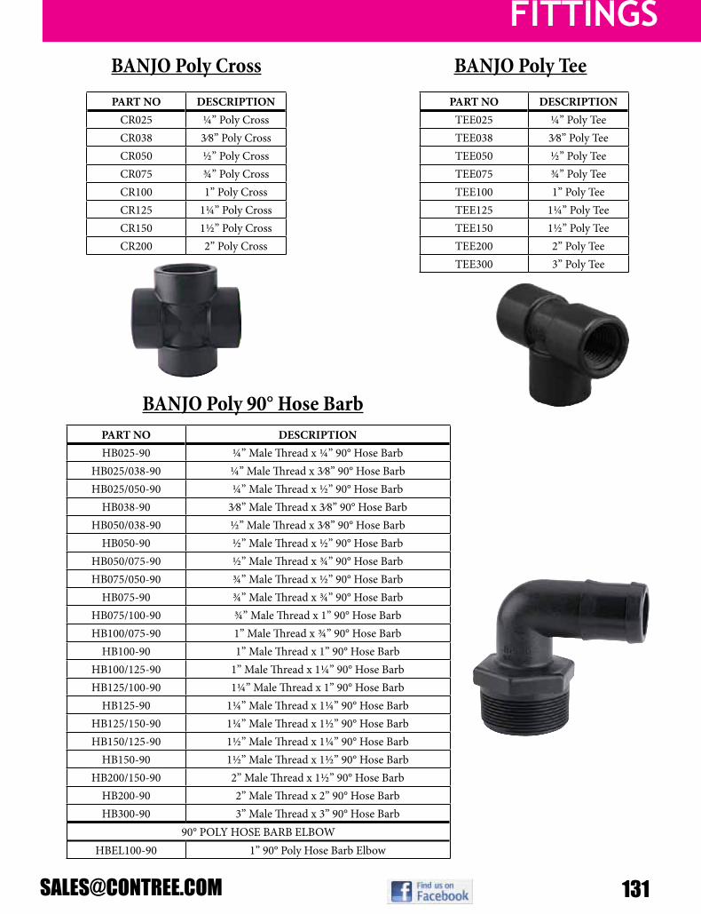
FITTINGS
PART NO DESCRIPTIONHB025-90 ¼” Male Thread x ¼” 90° Hose Barb
HB025/038-90 ¼” Male Thread x 3⁄8” 90° Hose BarbHB025/050-90 ¼” Male Thread x ½” 90° Hose Barb
HB038-90 3⁄8” Male Thread x 3⁄8” 90° Hose BarbHB050/038-90 ½” Male Thread x 3⁄8” 90° Hose Barb
HB050-90 ½” Male Thread x ½” 90° Hose BarbHB050/075-90 ½” Male Thread x ¾” 90° Hose BarbHB075/050-90 ¾” Male Thread x ½” 90° Hose Barb
HB075-90 ¾” Male Thread x ¾” 90° Hose BarbHB075/100-90 ¾” Male Thread x 1” 90° Hose BarbHB100/075-90 1” Male Thread x ¾” 90° Hose Barb
HB100-90 1” Male Thread x 1” 90° Hose BarbHB100/125-90 1” Male Thread x 1¼” 90° Hose BarbHB125/100-90 1¼” Male Thread x 1” 90° Hose Barb
HB125-90 1¼” Male Thread x 1¼” 90° Hose BarbHB125/150-90 1¼” Male Thread x 1½” 90° Hose BarbHB150/125-90 1½” Male Thread x 1¼” 90° Hose Barb
HB150-90 1½” Male Thread x 1½” 90° Hose BarbHB200/150-90 2” Male Thread x 1½” 90° Hose Barb
HB200-90 2” Male Thread x 2” 90° Hose BarbHB300-90 3” Male Thread x 3” 90° Hose Barb
90° POLY HOSE BARB ELBOWHBEL100-90 1” 90° Poly Hose Barb Elbow
PART NO DESCRIPTIONCR025 ¼” Poly CrossCR038 3⁄8” Poly CrossCR050 ½” Poly CrossCR075 ¾” Poly CrossCR100 1” Poly CrossCR125 1¼” Poly CrossCR150 1½” Poly CrossCR200 2” Poly Cross
PART NO DESCRIPTIONTEE025 ¼” Poly TeeTEE038 3⁄8” Poly TeeTEE050 ½” Poly TeeTEE075 ¾” Poly TeeTEE100 1” Poly TeeTEE125 1¼” Poly TeeTEE150 1½” Poly TeeTEE200 2” Poly TeeTEE300 3” Poly Tee
BANJO Poly TeeBANJO Poly Cross
BANJO Poly 90° Hose Barb

FITTINGS
132 800-433-3579
PART NO DESCRIPTION90° POLY ELBOWS
EL025-90 ¼” 90° Poly ElbowEL038-90 3⁄8” 90° Poly ElbowEL050-90 ½” 90° Poly ElbowEL075-90 ¾” 90° Poly ElbowEL100-90 1” 90° Poly ElbowEL125-90 1¼” 90° Poly ElbowEL150-90 1½” 90° Poly ElbowEL200-90 2” 90° Poly ElbowEL300-90 3” 90° Poly Elbow
45° POLY ELBOWEL100-45 1” 45° Poly Street Elbow
90° POLY STREET ELBOWSSL025-90 ¼” 90° Poly Street ElbowSL038-90 3⁄8” 90° Poly Street ElbowSL050-90 ½” 90° Poly Street ElbowSL075-90 ¾” 90° Poly Street ElbowSL100-90 1” 90° Poly Street ElbowSL125-90 1¼” 90° Poly Street ElbowSL150-90 1½” 90° Poly Street ElbowSL200-90 2” 90° Poly Street ElbowSL300-90 3” 90° Poly Street Elbow
45° POLY STREET ELBOWSSL075-45 ¾” 45° Poly Street ElbowSL100-45 1” 45° Poly Street ElbowSL125-45 1¼” 45° Poly Street ElbowSL150-45 1½” 45° Poly Street ElbowSL200-45 2” 45° Poly Street ElbowSL300-45 3” 45° Poly Street Elbow
PART NO DESCRIPTIONPOLY STRAIGHT HOSE BARBS
HB025 ¼” Male Thread x ¼” Hose BarbHB025-038 ¼” Male Thread x 3⁄8” Hose BarbHB025-050 ¼” Male Thread x ½” Hose Barb
HB038 3⁄8” Male Thread x 3⁄8” Hose BarbHB038-025 3⁄8” Male Thread x ¼” Hose BarbHB038-050 3⁄8” Male Thread x ½” Hose BarbHB050-025 ½” Male Thread x ¼” Hose BarbHB050-038 ½” Male Thread x 3⁄8” Hose Barb
HB050 ½” Male Thread x ½” Hose BarbHB050-075 ½” Male Thread x ¾” Hose BarbHB075-038 ¾” Male Thread x 3⁄8” Hose BarbHB075-050 ¾” Male Thread x ½” Hose BarbHB075-058 ¾” Male Thread x 5⁄8” Hose Barb
HB075 ¾” Male Thread x ¾” Hose BarbHB075-100 ¾” Male Thread x 1” Hose BarbHB100-075 1” Male Thread x ¾” Hose Barb
HB100 1” Male Thread x 1” Hose BarbHB100-125 1” Male Thread x 1¼” Hose BarbHB125-075 1¼” Male Thread x ¾” Hose BarbHB125-100 1¼” Male Thread x 1” Hose Barb
HB125 1¼” Male Thread x 1¼” Hose BarbHB125-150 1¼” Male Thread x 1½” Hose BarbHB150-100 1½” Male Thread x 1” Hose BarbHB150-125 1½” Male Thread x 1¼” Hose Barb
HB150 1½” Male Thread x 1½” Hose BarbHB150-200 1½” Male Thread x 2” Hose BarbHB200-150 2” Male Thread x 1½” Hose Barb
HB200 2” Male Thread x 2” Hose BarbHB300 3” Male Thread x 3” Hose BarbHB400 4” Male Thread x 4” Hose Barb
POLY FEMALE HOSE BARBSHBF075 ¾” Female ThreadHBF075-100 ¾” Female Thread x 1” Hose ShankHBF100 1” Female Thread x 1” Hose Shank
BANJO Poly Regular and Street ElbowsBANJO Poly Straight Hose Barb
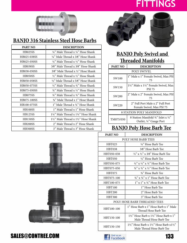
FITTINGS
PART NO DESCRIPTIONHB025SS ¼” Male Thread x ¼” Hose Shank
HB025-038SS ¼” Male Thread x 3⁄8” Hose ShankHB025-050SS ¼” Male Thread x ½” Hose Shank
HB038SS 3⁄8” Male Thread x 3⁄8” Hose ShankHB038-050SS 3⁄8” Male Thread x ½” Hose Shank
HB050SS ½” Male Thread x ½” Hose ShankHB050-058SS ½” Male Thread x 5⁄8” Hose ShankHB050-075SS ½” Male Thread x ¾” Hose ShankHB075-050SS ¾” Male Thread x ½” Hose Shank
HB075SS ¾” Male Thread x ¾” Hose ShankHB075-100SS ¾” Male Thread x 1” Hose ShankHB100-075SS 1” Male Thread x ¾” Hose Shank
HB100SS 1” Male Thread x 1” Hose ShankHB125SS 1¼” Male Thread x 1¼” Hose ShankHB150SS 1½” Male Thread x 1½” Hose ShankHB200SS 2” Male Thread x 2” Hose ShankHB300SS 3” Male Thread x 3” Hose Shank
PART NO DESCRIPTIONPOLY HOSE BARB TEES
HBT025 ¼” Hose Barb TeeHBT038 3⁄8” Hose Barb Tee
HBT050-038 ½” x ½” x 3⁄8” Hose Barb TeeHBT050 ½” Hose Barb Tee
HBT050-075 ½” x ½” x ¾” Hose Barb TeeHBT075-050 ¾” x ¾” x ½” Hose Barb Tee
HBT075 ¾” Hose Barb TeeHBT075-100 ¾” x ¾” x 1” Hose Barb TeeHBT100-075 1” x 1” x ¾” Hose Barb Tee
HBT100 1” Hose Barb TeeHBT200 2” Hose Barb TeeHBT300 3” Hose Barb Tee
POLY HOSE BARB THREADED TEES
HBT100-100 1” Hose Barb x 1” Hose Barb x 1” Male Thread Hose Barb Tee
HBT150-100 1½” Hose Barb x 1½” Hose Barb x 1” Male Thread Hose Barb Tee
HBT150-150 1½” Hose Barb x 1½” Hose Barb x1½” Male Thread Hose Barb Tee
PART NO DESCRIPTIONPOLY SWIVEL
SW100 1” Male x 1” Female Swivel, Max PSI 75
SW150 1½” Male x 1½” Female Swivel, Max PSI 75
SW200 2” Male x 2” Female Swivel, Max PSI 75
SW220 2” Full Port Male x 2” Full Port Female Swivel, Max PSI 75
8 STATION POLY MANIFOLD
TM075/050 8 Station Manifold ¾” Inlet x ½” Outlet, ¼” Gauge Port
BANJO 316 Stainless Steel Hose Barbs
BANJO Poly Swivel and Threaded Manifolds
BANJO Poly Hose Barb Tee

FITTINGS
134 800-433-3579
BANJO Poly Garden Hose Fittings
PART NO DESCRIPTION½” MINI T-STRAINER W/BLACK BOWL
LSTM050-30 ½” x ½” Black Bowl Strainer w/30 Mesh ScreenLSTM050-50 ½” x ½” Black Bowl Strainer w/50 Mesh ScreenLSTM050-80 ½” x ½” Black Bowl Strainer w/80 Mesh Screen
LSTM050-100 ½” x ½” Black Bowl Strainer w/100 Mesh Screen¾” MINI T-STRAINER W/BLACK BOWL
PART NO DESCRIPTIONLSTM075-30 ¾” x ¾” Black Bowl Strainer w/30 Mesh ScreenLSTM075-50 ¾” x ¾” Black Bowl Strainer w/50 Mesh ScreenLSTM075-80 ¾” x ¾” Black Bowl Strainer w/80 Mesh Screen
LSTM075-100 ¾” x ¾” Black Bowl Strainer w/100 Mesh ScreenFor Clear bowls add suffix “C” to part number “LSTM075-30C”
BANJO Poly Mini “T” Line Strainer
MESH SIZE RIB COLOR6 MESH WHITE
12 MESH BLACK20 MESH BEIGE30 MESH YELLOW40 MESH BROWN50 MESH RED80 MESH BLUE
100 MESH GREEN120 MESH BLACK
PART NO DESCRIPTION
GHFT075A ¾” Adapter x ¾” Garden Hose Female Thread
GHMT075B ¾” Coupler x ¾” Garden Hose Male Thread
GHFT075D ¾” Coupler x ¾” Garden Hose Female Thread
GHMT075F ¾” Adapter x ¾” Garden Hose Male Thread
GHFT075MPT ¾” Male NPT x ¾” Garden Hose Female Thread
GHMT075FPT ¾” Female NPT x ¾” Garden Hose Male Thread
GHMT075MPT ¾” Male NPT x ¾” Garden Hose Male Thread

FITTINGS
PART NO DESCRIPTION¾” T-STRAINER W/SS SCREENS
LST075-16 ¾” x ¾” T Strainer w/16 Mesh LST075-30 ¾” x ¾” T Strainer w/30 Mesh LST075-50 ¾” x ¾” T Strainer w/50 Mesh LST075-80 ¾” x ¾” T Strainer w/80 Mesh
LST075-100 ¾” x ¾” T Strainer w/100 Mesh 1” T-STRAINER W/SS SCREENS
LST100-16 1” x 1” T Strainer w/16 Mesh LST100-30 1” x 1” T Strainer w/30 Mesh LST100-50 1” x 1” T Strainer w/50 Mesh LST100-80 1” x 1” T Strainer w/80 Mesh
LST100-100 1” x 1” T Strainer w/100 Mesh 1¼” T-STRAINER W/SS SCREENS
LST125-16 1¼” x 1¼” T Strainer w/16 Mesh LST125-30 1¼” x 1¼” T Strainer w/30 Mesh LST125-50 1¼” x 1¼” T Strainer w/50 Mesh LST125-80 1¼” x 1¼” T Strainer w/80 Mesh
LST125-100 1¼” x 1¼” T Strainer w/100 Mesh 1½” T-STRAINER W/SS SCREENS
LST150-16 1½” x 1½” T Strainer w/16 Mesh LST150-30 1½” x 1½” T Strainer w/30 Mesh LST150-50 1½” x 1½” T Strainer w/50 Mesh LST150-80 1½” x 1½” T Strainer w/80 Mesh
LST150-100 1½” x 1½” T Strainer w/100 Mesh 2” SS Head & Poly Body T-STRAINER W/ SS SCREENS
LST200-04SS 2” x 2” T Strainer w/ 4 Mesh ScreenLST200-06SS 2” x 2” T Strainer w/ 6 Mesh ScreenLST200-08SS 2” x 2” T Strainer w/ 8 Mesh ScreenLST200-10SS 2” x 2” T Strainer w/10 Mesh ScreenLST200-16SS 2” x 2” T Strainer w/16 Mesh ScreenLST200-30SS 2” x 2” T Strainer w/30 Mesh ScreenLST200-50SS 2” x 2” T Strainer w/50 Mesh ScreenLST200-80SS 2” x 2” T Strainer w/80 Mesh Screen
LST200-100SS 2” x 2” T Strainer w/100 Mesh Screen
BANJO Poly & SS “T” Line Strainer BANJO “T” Line Strainer Parts List
Item Part No. Description Qty1 LST100-B ¾” & 1” Bowl 11 LST100BCB ¾” & 1” Clear Bowl 12 LST100-G ¾” & 1” EPDM Gasket 1
2 LST100-GV¾” & 1” FKM (viton type)
Gasket 13 12777 ½” Clean Out Plug 1
4 UV15163EPDM O-ring for Clean
Out Plug 1
4 UV15163VFKM (viton type) O-ring
for Clean Out Plug 15 LST1*** *** Mesh Screen 16 LST075-H ¾” Strainer Head 16 LST100-H 1” Strainer Head 1
7 13778 EPDM O-ring for Screen 1
Item Part No. Description Qty.
1 LST150-B* 1¼” & 1½” Bowl 1
1 LST150BCB 1¼” & 1½” Clear Bowl 1
2 LST150-G 1¼” & 1½” EPDM Gasket 1
2 LST150-GV 1¼” & 1½” FKM (viton type) Gasket 1
3 LSQ200-PL 1” Clean Out Plug 1
4 LSQ200-R EPDM O-Ring for Clean Out Plug 1
4 LSQ200-RV FKM (viton type) O-ring for Clean Out Plug 1
5 LST15*** **** Mesh Screen 1
6 LST125-H 1¼” Strainer Head 1
6 LST150-H 1½” Strainer Head 1
7 LST034G EPDM O-ring for Screen 1
LST125-HB 1¼” Strainer Head, Bowl & Gasket 1
LST150-HB 1½” Strainer Head, Bowl & Gasket 1
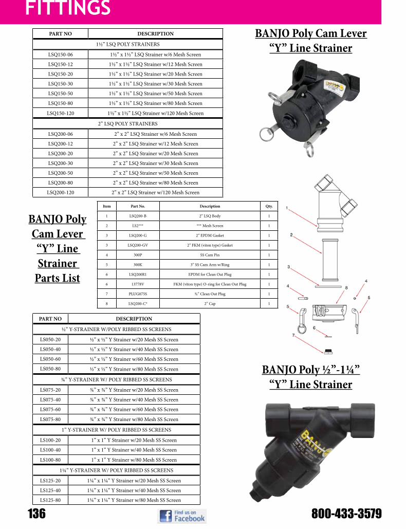
FITTINGS
136 800-433-3579
PART NO DESCRIPTION
1½” LSQ POLY STRAINERS
LSQ150-06 1½” x 1½” LSQ Strainer w/6 Mesh Screen
LSQ150-12 1½” x 1½” LSQ Strainer w/12 Mesh Screen
LSQ150-20 1½” x 1½” LSQ Strainer w/20 Mesh Screen
LSQ150-30 1½” x 1½” LSQ Strainer w/30 Mesh Screen
LSQ150-50 1½” x 1½” LSQ Strainer w/50 Mesh Screen
LSQ150-80 1½” x 1½” LSQ Strainer w/80 Mesh Screen
LSQ150-120 1½” x 1½” LSQ Strainer w/120 Mesh Screen
2” LSQ POLY STRAINERS
LSQ200-06 2” x 2” LSQ Strainer w/6 Mesh Screen
LSQ200-12 2” x 2” LSQ Strainer w/12 Mesh Screen
LSQ200-20 2” x 2” LSQ Strainer w/20 Mesh Screen
LSQ200-30 2” x 2” LSQ Strainer w/30 Mesh Screen
LSQ200-50 2” x 2” LSQ Strainer w/50 Mesh Screen
LSQ200-80 2” x 2” LSQ Strainer w/80 Mesh Screen
LSQ200-120 2” x 2” LSQ Strainer w/120 Mesh Screen
PART NO DESCRIPTION
½” Y-STRAINER W/POLY RIBBED SS SCREENS
LS050-20 ½” x ½” Y Strainer w/20 Mesh SS Screen
LS050-40 ½” x ½” Y Strainer w/40 Mesh SS Screen
LS050-60 ½” x ½” Y Strainer w/60 Mesh SS Screen
LS050-80 ½” x ½” Y Strainer w/80 Mesh SS Screen
¾” Y-STRAINER W/ POLY RIBBED SS SCREENS
LS075-20 ¾” x ¾” Y Strainer w/20 Mesh SS Screen
LS075-40 ¾” x ¾” Y Strainer w/40 Mesh SS Screen
LS075-60 ¾” x ¾” Y Strainer w/60 Mesh SS Screen
LS075-80 ¾” x ¾” Y Strainer w/80 Mesh SS Screen
1” Y-STRAINER W/ POLY RIBBED SS SCREENS
LS100-20 1” x 1” Y Strainer w/20 Mesh SS Screen
LS100-40 1” x 1” Y Strainer w/40 Mesh SS Screen
LS100-80 1” x 1” Y Strainer w/80 Mesh SS Screen
1¼” Y-STRAINER W/ POLY RIBBED SS SCREENS
LS125-20 1¼” x 1¼” Y Strainer w/20 Mesh SS Screen
LS125-40 1¼” x 1¼” Y Strainer w/40 Mesh SS Screen
LS125-80 1¼” x 1¼” Y Strainer w/80 Mesh SS Screen
BANJO Poly Cam Lever “Y” Line Strainer
BANJO Poly ½”-1¼” “Y” Line Strainer
Item Part No. Description Qty.
1 LSQ200-B 2” LSQ Body 1
2 LS2*** *** Mesh Screen 1
3 LSQ200-G 2” EPDM Gasket 1
3 LSQ200-GV 2” FKM (viton type) Gasket 1
4 300P SS Cam Pin 1
5 300K 3” SS Cam Arm w/Ring 1
6 LSQ200R1 EPDM for Clean Out Plug 1
6 13778V FKM (viton type) O-ring for Clean Out Plug 1
7 PLUG075S ¾” Clean Out Plug 1
8 LSQ200-C* 2” Cap 1
BANJO Poly Cam Lever
“Y” Line Strainer
Parts List
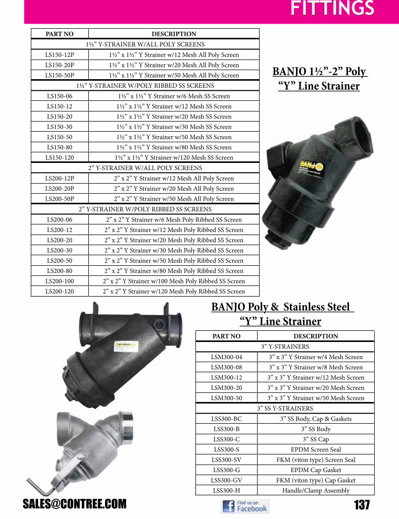
FITTINGS
PART NO DESCRIPTION1½” Y-STRAINER W/ALL POLY SCREENS
LS150-12P 1½” x 1½” Y Strainer w/12 Mesh All Poly ScreenLS150-20P 1½” x 1½” Y Strainer w/20 Mesh All Poly ScreenLS150-50P 1½” x 1½” Y Strainer w/50 Mesh All Poly Screen
1½” Y-STRAINER W/POLY RIBBED SS SCREENSLS150-06 1½” x 1½” Y Strainer w/6 Mesh SS ScreenLS150-12 1½” x 1½” Y Strainer w/12 Mesh SS ScreenLS150-20 1½” x 1½” Y Strainer w/20 Mesh SS ScreenLS150-30 1½” x 1½” Y Strainer w/30 Mesh SS ScreenLS150-50 1½” x 1½” Y Strainer w/50 Mesh SS ScreenLS150-80 1½” x 1½” Y Strainer w/80 Mesh SS Screen
LS150-120 1½” x 1½” Y Strainer w/120 Mesh SS Screen2” Y-STRAINER W/ALL POLY SCREENS
LS200-12P 2” x 2” Y Strainer w/12 Mesh All Poly ScreenLS200-20P 2” x 2” Y Strainer w/20 Mesh All Poly ScreenLS200-50P 2” x 2” Y Strainer w/50 Mesh All Poly Screen
2” Y-STRAINER W/POLY RIBBED SS SCREENSLS200-06 2” x 2” Y Strainer w/6 Mesh Poly Ribbed SS ScreenLS200-12 2” x 2” Y Strainer w/12 Mesh Poly Ribbed SS ScreenLS200-20 2” x 2” Y Strainer w/20 Mesh Poly Ribbed SS ScreenLS200-30 2” x 2” Y Strainer w/30 Mesh Poly Ribbed SS ScreenLS200-50 2” x 2” Y Strainer w/50 Mesh Poly Ribbed SS ScreenLS200-80 2” x 2” Y Strainer w/80 Mesh Poly Ribbed SS Screen
LS200-100 2” x 2” Y Strainer w/100 Mesh Poly Ribbed SS ScreenLS200-120 2” x 2” Y Strainer w/120 Mesh Poly Ribbed SS Screen
PART NO DESCRIPTION3” Y-STRAINERS
LSM300-04 3” x 3” Y Strainer w/4 Mesh ScreenLSM300-08 3” x 3” Y Strainer w/8 Mesh ScreenLSM300-12 3” x 3” Y Strainer w/12 Mesh ScreenLSM300-20 3” x 3” Y Strainer w/20 Mesh ScreenLSM300-50 3” x 3” Y Strainer w/50 Mesh Screen
3” SS Y-STRAINERSLSS300-BC 3” SS Body, Cap & GasketsLSS300-B 3” SS BodyLSS300-C 3” SS CapLSS300-S EPDM Screen Seal
LSS300-SV FKM (viton type) Screen SealLSS300-G EPDM Cap Gasket
LSS300-GV FKM (viton type) Cap GasketLSS300-H Handle/Clamp Assembly
BANJO 1½”-2” Poly “Y” Line Strainer
BANJO Poly & Stainless Steel “Y” Line Strainer

Hose
138 800-433-3579
Model Number Temp. Rating Nominal I.D.
Nominal O.D.
Working Pressure @ 68ºF
Working Pressure @ 104ºF Est. Ship Wt.
K4131-06X300 25 to 150ºF 3/8” 0.62” 600 psi 250 psi 35 lbsK4131-06X400 25 to 150ºF 3/8” 0.62” 600 psi 250 psi 46 lbsK4131-08X300 25 to 150ºF 1/2” 0.79” 600 psi 250 psi 54 lbsK4131-08X400 25 to 150ºF 1/2” 0.79” 600 psi 250 psi 72 lbs
PVC 600# Reinforced Spray Hose
Item # I.D. O.D. Max. Pressure(70ºF)
Max. Pressure (122ºF) Length Est. Ship
WtK4350-06X300 3/8 in 0.590 in 300 psi 100 psi 300 ft. 22.0 lbK4350-06X500 3/8 in 0.590 in 300 psi 100 psi 500 ft. 41.0 lbK4350-08X300 1/2 in 0.720 in 250 psi 75 psi 300 ft. 26.0 lbK4350-08X500 1/2 in 0.720 in 250 psi 75 psi 500 ft. 51.0 lbK4350-12X300 3/4 in 0.970 in 150 psi 40 psi 300 ft. 36.0 lbK4350-16X200 1 in 1.310 in 150 psi 30 psi 200 ft. 47.0 lb
Series K4350 EVA Yarn-Reinforced Spray Hose
Ethylene vinyl acetate reinforced with a synthetic cord. Highly flexible, extremely tough with a very good stress and crack resistance at low temps (10-150°F). Suited for use in low and medium pressure agricultural sprayer lines.
KLEARON 73 Series K010 Clear PVC TubingItem # I.D. O.D. Max. Pressure
(70ºF) Length Est. Ship Wt
K010-0408X100 1/4 in 0.500 in 60 psi 100 ft. 8.00 lbK010-0610X100 3/8 in 0.620 in 55 psi 100 ft. 10.7 lbK010-0812X100 1/2 in 0.750 in 45 psi 100 ft. 13.4 lbK010-1014X100 5/8 in 0.880 in 40 psi 100 ft. 16.1 lbK010-1220X100 3/4 in 1.250 in 45 psi 100 ft. 42.9 lbK010-1624X100 1 in 1.500 in 35 psi 100 ft. 53.6 lbK010-2028X50 1 1/4 in 1.750 in 40 psi 50 ft. 32.2 lbK010-2432X50 1 1/2 in 2.000 in 35 psi 50 ft. 37.5 lbK010-3240X50 2 in 2.500 in 35 psi 50 ft. 48.2 lb
High gloss crystal clear appearance with glass smooth interior to reduce sediment buildup, Self-extinguishing, Compound hardness 73 Shore “A”, formulated with ingredients in compliance with applicable FDA(03) requirements, meets USDA(17), 3A(01), NSF(13), UL(16), RoHS(15) and USP(18) Class VI criteria
Item # I.D. O.D. Max. Pressure(70ºF)
Max. Pressure (122ºF) Length Est. Ship
WtK3150-04X300 1/4 in 0.440 in 250 psi 150 psi 300 ft. 17.0 lbK3150-06X300 3/8 in 0.590 in 225 psi 125 psi 300 ft. 27.0 lbK3150-08X300 1/2 in 0.750 in 200 psi 100 psi 300 ft. 40.0 lbK3150-12X200 3/4 in 1.030 in 150 psi 85 psi 200 ft. 43.0 lbK3150-16X200 1 in 1.300 in 125 psi 75 psi 200 ft. 59.0 lb
CLEARBRAID® K3150 Series RF Standard Wall PVC Hose
Crystal clear PVC compound, formulated with ingredients in compliance with applicable FDA(03) requirements, meets USDA(17), 3A(01), NSF(13), UL(16), RoHS(15) and USP(18) Class VI criteria. Reinforced with spiraled polyester yarn and longitudinal orange tracer yarns for identification.

Hose
K™ Series Standard Duty PVC Suction HoseItem # I.D. O.D. Working Pressure
(68ºF)Working Pressure
(104ºF) Weight
K075X100 3/4 in 1.010 in 110 psi 70 psi 0.19 lbs/ft.K100X100 1 in 1.260 in 85 psi 60 psi 0.26 lbs/ft.K125X100 1 1/4 in 1.560 in 85 psi 60 psi 0.35 lbs/ft.K150X100 1 1/2 in 1.830 in 70 psi 50 psi 0.48 lbs/ft.K200X100 2 in 2.320 in 65 psi 45 psi 0.66 lbs/ft.
TIGERFLEX “TG” Sludge EPDM Suction
Hose
Model Number Temp. Rating Nominal I.D.
Nominal O.D.
Working Pressure @ 68ºF
Working Pressure @ 104ºF Weight/Ft.
TG100X100 (-40) to 160ºF 1” 1.4” 65 psi 45 psi .28 lbsTG125X100 (-40) to 160ºF 1-1/4” 1.63” 60 psi 40 psi .33 lbsTG150X100 (-40) to 160ºF 1-1/2” 1.93” 50 psi 35 psi .44 lbsTG200X100 (-40) to 160ºF 2” 2.51” 50 psi 35 psi .67 lbsTG250X100 (-40) to 160ºF 2-1/2” 3.07” 45 psi 30 psi .95 lbsTG300X100 (-40) to 160ºF 3” 3.6” 45 psi 30 psi 1.14 lbsTG400X100 (-40) to 160ºF 4” 4.7” 40 psi 25 psi 1.84 lbsTG600X100 (-40) to 160ºF 6” 6.85” 30 psi 20 psi 3.07 lbs
Part # I.D. x O.D. Length Vac. Rat. M.B.R. W.P. Wt. Ea.12012795 1” x 1.34” 100’ 28 in/HG 4.0” 80# 23.0#12012797 1-1/4” x 1.61” 100’ 28 in/HG 5.0” 70# 30.0#12012800 1-1/2” x 1.96” 100’ 28 in/HG 6.0” 60# 47.0#12012805 2” x 2.49” 100’ 28 in/HG 9.0” 60# 69#12012807 2-1/2” x 3.00” 100’ 28 in/HG 11.0” 50# 93#12012810 3” x 3.60” 100’ 28 in/HG 12.0” 50# 119#12012815 4” x 4.69” 100’ 28 in/HG 17.0” 45# 181#12012928 6” x 6.86” 100’ 28 in/HG 27.0” 35# 348#
Shorter lengths available by order, longest length available is 100’ spools.
Fertilizer Solution“Bumble Bee” EPDM Suction Hose
“Bumble-Bee”
Tigerflex “TG”
“K” Style

Hose
140 800-433-3579
Part # I.D. x O.D. Length M.B.R. W.P. Est Ship Wt
12003485 1” x 1-1/2” 100’ 4.0” 150# 50#12003490 1-1/4” x 1-23/32” 100’ 6.0” 150# 60#12003501 1-1/2” x 2” 100’ 8.0” 150# 82#12004001 2” x 2-1/2” 100’ 10.0” 150# 101#12004106 2-1/2” x 3” 100’ 14.0” 150# 150#12004508 3” x 3-17/32” 100’ 22.0” 150# 175#12005700 3-1/2” x 4” 100’ 14.0” 150# 235#12005008 4” x 4-3/4” 100’ 22.0” 100# 240#12005504 6” x 6-7/8” 100’ 30.0” 100# 484#
EDPM Reinforced Rubber Suction Hose
Part # I.D. x O.D. Length Spiral W.P.10040507 1-1/4” x 1-25/32” 250’ 4 200#10041007 1-1/2” x 2-1/32” 200’ 4 200#10041011 2” x 2-1/2” 300’ 4 150#
Part # I.D. x Ft. Est Ship Wt10031713 3/8” x 350’ 61.3#10031714 1/2” x 200’ 48.2#10031715 5/8” x 200’ 57.4#10031716 3/4” x 150’ 59.6#10031717 1” x 100’ 51.8#
Part # I.D. x Ft. Est Ship Wt10031664 3/8” x 400’ 60.4#10031665 1/2” x 250’ 60.0#10031666 5/8” x 225’ 64.4#10031667 3/4” x 150’ 54.5#10031668 1” x 125’ 54.1#
Versatile general purpose hose, which is excellent for air and water service as well as many agricultural chemicals includingLASSO®herbicide.TheEPDMtubeandcoverresists heat, sunlight, ozone and weathering. Exceeds RMA class C medium oil resistance requirements.
Versatile general purpose hose, which is excellent for air and water service as well as many agricultural chemicalsincludingLASSO®herbicide.TheEPDMtubeandcoverresistsheat, sunlight, ozone and weathering. Exceeds RMA class C medium oil resistance requirements.
Suitable for applications such as oil mist lubricating air lines, but NOT suitable for the transfer of petroleum products. Construction: Closely plied reinforcement of 2 or 4 spiral high tensile textile cord provides excellent coupling retention and kink resistance.
AG200 EPDM Rubber Spray Hose
AG300 EPDM Rubber Spray Hose
AG3000 EPDM Rubber Spray Hose

reel
MODEL LBS Hose I.D. Hose O.D. Max Feet PSIW H L
Overall Dimensions1125-4-100-E 49 1/2” 7/8” 100 3000 19-3/4” 19-1/4” 17-5/8”1125-4-200-E 52 1/2” 7/8” 200 3000 25-3/4” 19-1/4” 17-5/8”1125-4-325-E 61 1/2” 7/8” 325 3000 31-3/4” 19-1/4” 17-5/8”1125-4-450-E 65 1/2” 7/8” 450 3000 37-3/4” 19-1/4” 17-5/8”1125-4-500-E 71 1/2” 7/8” 500 3000 41-3/4” 19-1/4” 17-5/8”1125-5-50-E 51 3/4” 1-1/4” 50 3000 20” 19-1/4” 17-5/8”
1125-5-100-E 55 3/4” 1-1/4” 100 3000 26” 19-1/4” 17-5/8”1125-5-175-E 63 3/4” 1-1/4” 175 3000 32” 19-1/4” 17-5/8”1125-5-200-E 68 3/4” 1-1/4” 200 3000 38” 19-1/4” 17-5/8”1125-5-250-E 72 3/4” 1-1/4” 250 3000 42” 19-1/4” 17-5/8”1125-6-35-E 63 1” 1-7/16” 35 3000 23-7/8” 19-1/8” 17-5/8”1125-6-50-E 68 1” 1-7/16” 50 3000 29-7/8” 19-1/8” 17-5/8”1125-6-75-E 75 1” 1-7/16” 75 3000 36-3/8” 19-1/8” 17-5/8”
1125-6-100-E 82 1” 1-7/16” 100 3000 42-3/8” 19-1/8” 17-5/8”For Manual reels, remove “-E” designation from Model #. Weight is appx. 13 lbs less. Dimensions smaller overall.
COX 1125 Series Hose ReelsHand Crank & Electric Rewind
MODEL LBS Hose I.D. Hose O.D. Max Feet PSIW H L
Overall Dimensions1175-6-50-E 80 1” 1-7/16” 50 3000 22” 26-1/8” 24”
1175-6-100-E 83 1” 1-7/16” 100 3000 26” 26-1/8” 24”1175-6-125-E 85 1” 1-7/16” 125 3000 28” 26-1/8” 24”1175-6-135-E 83 1” 1-7/16” 135 3000 34-1/2” 22-7/8” 20”1175-6-150-E 88 1” 1-7/16” 150 3000 30” 26-1/8” 24”1175-6-200-E 96 1” 1-7/16” 200 3000 34-1/2” 26-1/8” 24”
For Manual reels, remove “-E” designation from Model #. Weight is appx. 13 lbs less. Dimensions smaller overall.
COX 1175 Series Hose ReelsHand Crank & Electric Rewind

reel
142 800-433-3579
Cox Reel Parts Breakdown (1125 shown for reference)
Add “SS” Polished or “SP” Satin suffix to the Model number you would like to order. For more information on Stainless Reels do not hesitate to contact us at [email protected] or 800-433-3579. Any of our sales associates will be able to assist you!
Many Cox Reels are available in a Stainless Steel option.

reel
MODEL LBS Hose I.D. Hose O.D. Max Feet Max PSIW H L
Overall Dimensions in Inches1514-17-18E 45 ½” 7/8” 75 3000 16.5 18.2 191516-17-18E 46 ½” 7/8” 125 3000 18.5 18.2 191520-17-18E 47 ½” 7/8” 175 3000 22.5 18.2 191526-17-18E 49 ½” 7/8” 300 3000 28.5 18.2 191530-17-18E 51 ½” 7/8” 375 3000 32.5 18.2 191536-17-18E 53 5/8” 1” 350 3000 38.5 18.2 19
For Manual reels, remove “E” designation from Model #. Weight is appx. 12 lbs less. Dimensions smaller overall.
Hannay 1500 Series Hose Reels: Manual and Electric Rewind
MODEL LBS Hose I.D. Hose O.D. Max Feet Max PSIW H L
Overall Dimensions in Inches1836-17-18E 36 ¾” 1 9/32” 200 1000 18.5 18.2 191816-17-18E 28 ¾” 1 9/32” 50 1000 24.5 18.2 191822-17-18E 30 ¾” 1 9/32” 100 1000 28.5 18.2 191826-17-18E 32 ¾” 1 9/32” 125 1000 32.5 18.2 191830-17-18E 33 ¾” 1 9/32” 150 1000 38.5 18.2 19
For Manual reels, remove “E” designation from Model #. Weight is appx. 12 lbs less. Dimensions smaller overall.
Hannay 1800 Series Hose Reels: Manual and Electric Rewind
MODEL LBS Hose I.D. Hose O.D. Max Feet Max PSIW H L
Overall Dimensions in Inches4018-17-18E 54 1” 1 9/16” 35 2000 20.5 18.2 194024-17-18E 64 1” 1 9/16” 50 2000 26.5 18.2 194030-17-18E 75 1” 1 9/16” 75 2000 32.5 18.2 194038-17-18E 88 1” 1 9/16” 100 2000 40.5 18.2 19
For Manual reels, remove “E” designation from Model #. Weight is appx. 12 lbs less. Dimensions smaller overall.
Hannay 4000 Series Hose Reels: Manual and Electric Rewind
MODEL LBS Hose I.D. Hose O.D. Max Feet PSI
W H LOverall Dimensions
SM12-3-100 15 3/8” 5/8” 100 4000 19” 13-1/2” 12”SM17-3-250 26 3/8” 5/8” 250 4000 19” 18-1/2” 17”SM17-4-125 26 1/2” 7/8” 125 4000 19” 18-1/2” 17”
SMK-202 8 Pivoting base for wall mounting only. Heavy gauge steel construction, powder coated crinkle black, Includes rigid arm with 8-position locking pivot base
COX SM Series Hose Reels Hand Crank
COX Hose Reel GuidesMany COX Reel Guides are available.
For more information on Reel Guides do not hesitate to contact us at [email protected] or 800-433-3579. Any of our sales associates will be able to assist you!

reel
144 800-433-3579
MODEL LBS Hose I.D. Hose O.D. Max Feet Max PSIW H L
Overall Dimensions in Inches6024-19-21E 125 1” 1 9/16” 60 2000 28.5 21.5 20.56032-19-21E 142 1” 1 9/16” 100 2000 37 21.5 20.56024-23-24E 132 1” 1 9/16” 100 2000 28.5 23.5 20.56030-23-24E 145 1” 1 9/16” 150 2000 35 23.5 20.56038-23-24E 160 1” 1 9/16” 200 2000 42.5 23.5 20.56016-25-26E 128 1” 1 9/16” 60 2000 20.5 27.9 25.56022-25-26E 140 1” 1 9/16” 100 2000 26.5 27.9 25.56028-25-26E 153 1” 1 9/16” 200 2000 33 27.9 25.56018-30-31E 141 1” 1 9/16” 135 2000 22.5 29.9 25.56024-30-31E 153 1” 1 9/16” 200 2000 28.5 29.9 25.56028-30-31E 161 1” 1 9/16” 265 2000 33 29.9 25.56030-30-31E 165 1” 1 9/16” 300 2000 35 29.9 25.56028-33-34E 169 1” 1 9/16” 350 2000 32.75 33.7 31.5
For Manual reels, remove “E” designation from Model #. Weight is appx. 12 lbs less. Dimensions smaller overall.
Hannay 6000 Series Hose Reels: Manual and Electric Rewind
Hannay Utility Hose Rollers
Hannay Stainless Steel Reels
Many Hannay Reels are available in a Stainless Steel option.
Add “SS” prefix to the Model number you would like to order. For more information on Stainless Reel do not hesitate to contact us at [email protected] or 800-433-3579. Any of our sales associates will be able to assist you!
B
XA
F
C G
H
YDE
16
SeriesN600sPring reWind reels
• Lubrication • Air/Water • Assembly Operations• Washdown • Air Tools • General Industrial Applications
Hannay Reels, Inc.Phone: 518-797-3791Toll Free: 1-877-467-3357
Domestic FAX: 1-800-733-5464International FAX: 518-797-3259
B
C
XAF E
DY
G
HPart ii: accessorY ordering guide
Accessories• Roller Assemblies for Spring Rewind Reels • Utility Hose Rollers • Hose Guide
Roller Assemblies for Spring Rewind ReelsThese 4-way roller assemblies are for use on the reel, on cabinet door openings, and for similar locations where sharp metal edges may cut or damage the hose/cable. Four-way design protects hose even when payout or rewind is at an angle.The N200 and R200 roller assemblies have Delrin rollers mounted in stamped steel housings for flush panel mounting, reel mounting (R200) or right-angle mounting (N200).The R300 roller assemblies have stainless steel rollers, Delrin bearing inserts, and zinc die-cast corner mounting blocks assembled on a steel mounting frame.To Order: Specify part numbers: N Models for N Series reels, R Models for Channel Frame reels.Note: A hose stop should be used with 4-way rollers to prevent damage to rollers and nozzles. See description on page 15.
Utility Hose Rollers
Part Number
Overall Dimensions Roller OpeningInches mm Inches mm
R203 8.0 x 5.5 203.2 x 139.7 2.5 x 2.0 63.5 x 50.8R204 9.0 x 5.5 228.6 x 139.7 3.5 x 2.0 88.9 x 50.8R205 10.0 x 5.5 254.0 x 139.7 4.5 x 2.0 114.3 x 50.8R206 11.0 x 5.5 279.4 x 139.7 5.5 x 2.0 139.7 x 50.8N203 5.5 x 5.5 139.7 x 139.7 2.5 x 2.0 63.5 x 50.8N204 6.5 x 5.5 165.1 x 139.7 3.5 x 2.0 88.9 x 50.8N205 7.5 x 5.5 190.5 x 139.7 4.5 x 2.0 114.3 x 50.8N206 8.5 x 5.5 215.9 x 139.7 5.5 x 2.0 139.7 x 50.8R306 11.25 x 7.0 285.8 x 177.8 5.5 x 2.38 139.7 x 60.45R308 13.25 x 7.0 336.6 x 177.8 7.5 x 2.38 190.5 x 60.45R310 15.25 x 7.0 387.4 x 177.8 9.5 x 2.38 241.3 x 60.45PW-2R 9.75 x 3.75 247.7 x 95.3 5.13 x 1.13 130.3 x 28.7EH-714 9 x 5.625 228.6 x 142.9 2.5 x 2.5 63.5 x 63.5
N200 R200 R300
PW-2R Roller EH-714
HG-15 Hose Guide for Small Frame Models
1.38
.88
1.38
1.88
Z
X
ZW Y
X
Z
X
Z
X
ZW Y
X
Z
X
Z
X
ZW Y
X
Z
X
Assembly A/A2 Assembly B/B2 Assembly C/C2 Assembly C Assembly C2
C shown
C2 shown
1500 Series shown
Stainless steel rollers and cast alloy brackets for use on the reel, on cabinet door openings, truck platforms, and similar locations where sharp edges may cut or damage hose/cable.Specifications: 1-1/2" diameter stainless steel roller, stainless steel rod, Delrin bearings, alloy brackets, and required fasteners.To Order: Specify Assembly A, B or C, and give distance between each pair of mounting holes (Dimensions X and Y) and length of each roller (Dimensions W and Z). W=Vertical Roller Length, Z=Horizontal Roller Length.Also available factory installed on the reel.
• Available for our 1500, 1600, and 1800 Series reels.
• Simple design to rewind hose evenly and neatly every time.
• No need to handle dirty or contaminated hose.
• Powder coated bracket, stainless steel guide rods, and nylon rollers assure long service life.
• Designed for aftermarket installation.
Hose Guide Kit – HGK-15 Hannay Part Number 9956.2200Kit includes HG-15 Hose Guide, handle grip, 2 stainless steel guide rods, 4 mounting blocks, steel mounting bracket set, and all mounting hardware.
Hose Guide – HG-15 Hannay Part Number 9956.2000Assembled black powder coated hose guide and handle grip.You must specify reel model when ordering.
Back view of HG-15
To Order: Specify Assembly A, B or C, and give distance between each pair of mounting holes (Dimensions X and Y) and length of each roller (Dimensions W and Z). W=Vertical Roller Length, Z=Horizontal Roller Length.
Stainless steel rollers and cast alloy brackets for use on the reel, on cabinet door openings, truck platforms, and similar locations where sharp edges may cut or damage hose/cable.Specifications: 1-1/2” diameter stainless steel roller, stainless steel rod, Delrin bearings, alloy brackets, and required fasteners.

reel
Hannay Hose Reel Parts List (1500 Series shown for Reference)Item No Description PART
NUMBER Qty Item No Description PART NUMBER Qty
02a Self Aligning Bearing Complete - (1/2” Bore) 9902.12 2 28a 3/8” Flat Washer 9954.001 4
02b Self Aligning Bearing Holder 9902.280 2 28b Disc Sprocket Spacer 9954.002 6
02c Self Aligning Bearing Pillowblock 9902.290 2 28c Hub Spacer 9954.002 As/N
02d Self Aligning Bearing Insert - (1/2” Bore) 9902.130 2 28d Disc Washer 9965.004 2
6 #35 Chain 9912.003 1 32 Hub Assembly - Straight Iron Pipe 9901.105 1
7 Chain Guard, Molded 9957.003 1 55c 1/2” Pipe Cap 9965.001 1
12 17-18 Disc 9903.052 2 72a 112T35 x 13-3/8” Dia Disc Sprocket 9910.132 1
13 Drum - Aluminum - 6” Dia. (Specify Model) 9905.711 1 Optional Removable Crank Rewind
20 Frame Assembly 1500 Series (Complete) 9908.100 1 25n Crank Handle Bolt w/ Nut 9914.051 1
20a Frame, 1500 Series 9906.001 2 30 Hand Crank Handle 9914.051
20b Foot, 1500 Series 9907.600 2 55a Hand Crank 9914.005 1
25a 1/4” - 20 X 1/4” Allen Set Screw 9958.000 2 55b 1/2” Adapter for Removable Crank 9914.005 1
25c 1/4” - 20 x 3/4” Hex Washer Head Black Zinc Screw 9904.107 2 Air Motor Only
25d 1/4” - 20 x 1/2” Hex Washer Head Tap Tight Screw 9904.107 2 25b 1/4” - 20 X 1/4” Spinlock Bolt 9904.106 3
25e 5/16” - 18 x 3/4” Spinlock Bolt 9904.210 12 57 #4 AM Gast Air Motor (Face Mount) 9918.112 1
25f 3/8” - 16 x 3/4” Bearing Bolt 9904.020 4 57a Speed Control Muffler 9919.001 1
25g 3/8” - 16 x 3/4” Spinlock Bolt 9904.220 4 57b Schrader Valve # 3420 9919.000 1
25h 3/8”-16 x 1” Button Head Cap Screw 9904.920 6 57c 18” x 1/4” x 1/4” Air Hose 9919.001 1
25k 3/8” - 16 Carriage Bolt Specify Model 4 57d 1/4” 90 Deg Pipe Elbow 9950.001 1
25m 1/2”-13 x 1” Hex Head Bolt 9904.140 2 66 Motor Mounting Plate - Air Motor 9923.001 1
27a 1/4” - 20 Spinlock Nut 9904.600 2 72 9T35 X 1-3/4” Motor Sprocket - Air Motor 9910.102 1
27b 5/16” - 18 Spinlock Nut 9904.560 8 Electric Motor Only
27c 3/8” - 16 Spinlock Nut 9904.620 18 58 227 12V DC Non Explosion Proof Motor (Face Mount) 9915.004 1
27d 1/2” - 13 Hex Head Nut 9904.540 2 66 Motor Mounting Plate - Electric Motor 9923.001 1
72 11T35 x 1-3/4” Motor Sprocket - Electric Motor 9910.112 1

HANDGUNS
146 800-433-3579
Features:• Interchangeable nozzle tips are color coded for easy identification of nozzle tip size.• Nozzle tips provide a 45° full cone
“showerhead” spray pattern.• Convenient trigger lock for continuous spraying.• Options available: hose shank swivel for inlet
connection and extension wand and adapters for low-volume and spot spraying.
• Maximum operating pressure of 200 psi• MadeofnylonwithViton®O-ringsand
stainless steel springs.
ITEM Part Number Description* PK-AB25660-Kit Spare Parts Kit (includes #2, 7, 9)
1CP25670-1.5-NY Nozzle, Gray--1.5
CP25670-3.0-NYB Nozzle, Black--3.0CP25670-4.0-NY Nozzle, Red--For #4.0
2* CP7717-2/22-VI O-ring, Viton3 CP25661-NYB Body, Nylon (Black) 3/4 NPT #256604 CP25662-NYB Cover, Nylon (Black)5 CP25676-IZP #8 Plastite Screw, Steel, Zinc Plated6 25675-NY Trigger Sub-Assembly, Nylon7* 25665 Stem Sub-Assembly. Nylon, Polypropylene and Viton8 CP25671-302SS Spring, Type 302 Stainless Steel9* 25663 Seating Sub-Assembly, Polypropylene with Viton
TeeJet Lawn Spray Gun Parts List
Model Nozzle Tip Capacity (in GPM)Number Number 2 psi 4 psi 6 psi 8 psi 10 psi 15 psi 20 psi
25660-1.5 25670-1.5-NY 1.4 1.9 2.3 2.6 2.9 3.4 425660-3.0 25670-3.0-NY 2 2.7 3.2 3.6 4.1 4.9 5.625660-4.0 25670-4.0-NY 2.3 3.1 3.7 4.3 4.7 5.6 6.4
TeeJet Lawn Spray Gun
25990 Swivel Allows operator to concentrate on application without hose interference. 3/4” (M) NPTconnection with 1/2” hose shank. Maximum pressure of 150 psi
25657-NYB Adapter
Replaces shower nozzle to allow extension wand or standard TeeJet tip to be attached directly to lawn spray gun. 3/4” (F) GHT inlet with 11/16”-16 TeeJet thread outlet.
Maximum pressure of 150 psi
22665 Extension Wand
For low volume and spot spraying applications. Available in both 15” and 24” lengths, the extension fits on 25657-NYB adapter. Maximum pressure of 150 psi
CP22673-PP 45° angle adapter for attaching standard TeeJet tips or adjustable ConeJet nozzles
CP22664-PP Straight adapter for attaching standard TeeJet tips or adjustable ConeJet nozzles

HANDGUNS
TeeJet Poly Hand Gun & Spray Tips
Features• Maximum pressure rating of 150 psi (10 bar).• With choice of 1/4” or 3/8” hose shank and a 1/4” NPT or BSPT (F) thread inlet connection.• Trigger lock permits locking gun in an open position for continuous flow (optional).• 22665 extension wand with choice of 15” (381 mm) or 24” (610 mm) lengths.• 38720-PPB-X8adjustableConeJet®spraytipwithViton®O-ring.• CP22673-PP 45° and CP22664-PP straight adapters (other capacities available).• Accepts all standard TeeJet spray tips and strainers.
Features• Choice of 1/4” or 3/8” hose shank and 1/4”
NPT or BSPT (F) thread inlet connection.• Replaceable diaphragm made of Viton.• Trigger lock permits locking gun in an open
position for continuous flow (optional).• Maximum operating pressure of 150 psi (10
bar).• Accepts all standard TeeJet spray tips and tip
strainers.
Model Number
Extension Length
Inlet Connection
Tip Number
(B)22670-PP-15-1/4 15” (381 mm) 1/4” (F)
38720-PP-X8 (stan-dard nozzle shipped
with TriggerJet)
22670-PP-15-300 15” (381 mm) 1/4” Hose Shank22670-PP-15-406 15” (381 mm) 1/4” Hose Shank
(B)22670-PP-24-1/4 24” (610 mm) 1/4” (F)22670-PP-24-300 24” (610 mm) 1/4” Hose Shank22670-PP-24-406 24” (610 mm) 3/8” Hose Shank
Model Number
Extension Length
Inlet Connection
Tip Number
(B)22650-PP-1/4NONE
1/4” (F)NONE22650-PP-300 1/4” Hose Shank
22650-PP-406 3/8” Hose Shank
5500Knurled body of tip rotates through a half turn to provide spray selection from wide angle, finely atomized cone spray to a straight stream spray. Tip set-tings “A” and “B” represent two extreme points of rotation in tip adjustment. Other sizes available.
5500-PP
The 5500 adjustable ConeJet tip is also available in a polypropyl-ene version. The polypropylene tip has the same performance characteristics as the brass tip and provides excellent chemical resistance. This tip’s light weight makes it well suited for use on handheld and backpack type sprayers.
“ChemLawn” Turf GunFeatures:• Durable nylon construction is corrosion resistant• Made in the USA, easy to repair, trigger lock
Part Number Description Flow (GPM)007433 ChemLawn Turf Gun No Nozzle018104 Blue 1.5009510 Yellow 2007668 Green 3007655 White 4
TeeJet Poly Hand Gun Extension
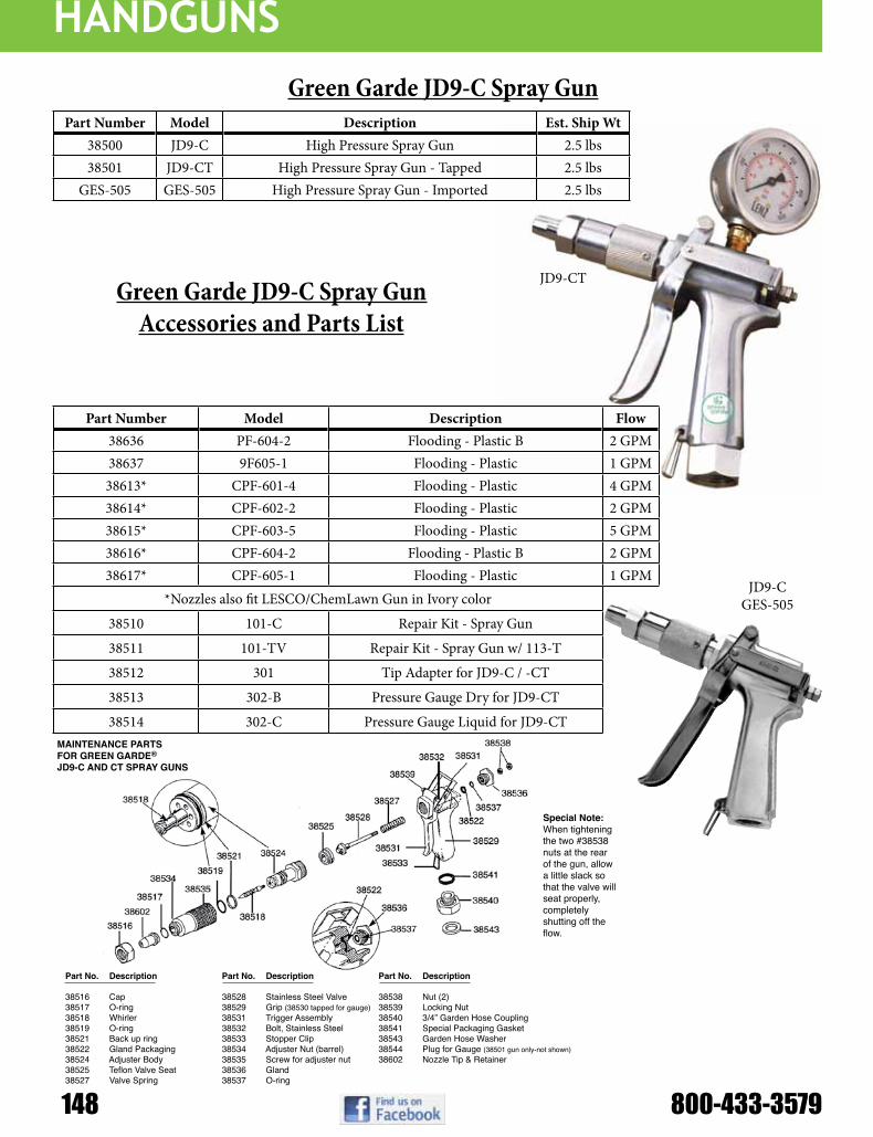
HANDGUNS
148 800-433-3579
MAINTENANCE PARTS FOR GREEN GARDE® JD9-C AND CT SPRAY GUNS
Special Note:When tightening the two #38538 nuts at the rear of the gun, allow a little slack so that the valve will seat properly, completely shutting off the flow.
JD-9C AND CT SPRAY GUNS (38500 & 38501)
MAINTENANCE PARTS FOR GREEN GARDE® JD9-PT SPRAY GUN
38516
38602
38517
38525
38543
38540
3854138533
38531
3853938532
38531
38529
38537
38538
38536
38522
Special Note:When tightening the two #38538 nuts at the rear of the gun, allow a little slack so that the valve will seat properly, completely shutting off the flow.
JD-9PT SPRAY GUN (38507)
38527
38548 38547
Part No. Description Part No. Description Part No. Description
38516 Cap 38528 Stainless Steel Valve 38538 Nut (2)38517 O-ring 38529 Grip (38530 tapped for gauge) 38539 Locking Nut38518 Whirler 38531 Trigger Assembly 38540 3/4” Garden Hose Coupling38519 O-ring 38532 Bolt, Stainless Steel 38541 Special Packaging Gasket38521 Back up ring 38533 Stopper Clip 38543 Garden Hose Washer38522 Gland Packaging 38534 Adjuster Nut (barrel) 38544 Plug for Gauge (38501 gun only-not shown)38524 Adjuster Body 38535 Screw for adjuster nut 38602 Nozzle Tip & Retainer38525 Teflon Valve Seat 38536 Gland 38527 Valve Spring 38537 O-ring
Part No. Description Part No. Description Part No. Description
38516 Cap 38532 Bolt, Stainless Steel 38541 Special Packaging Gasket38517 O-ring 38533 Stopper Clip 38543 Garden Hose Washer38522 Gland Packaging 38536 Gland 38544 Plug for Gauge (38501 gun only-not shown)38525 Teflon Valve Seat 38537 O-ring 38547 Whirler Valve Stem38527 Valve Spring 38538 Nut (2) 38548 Gun Barrel38529 Grip (38530 tapped for gauge) 38539 Locking Nut 38602 Nozzle Tip & Retainer38531 Trigger Assembly 38540 3/4” Garden Hose Coupling
FAST FAX BULLETIN 86387
Green Garde JD9-C Spray GunPart Number Model Description Est. Ship Wt
38500 JD9-C High Pressure Spray Gun 2.5 lbs38501 JD9-CT High Pressure Spray Gun - Tapped 2.5 lbs
GES-505 GES-505 High Pressure Spray Gun - Imported 2.5 lbs
Part Number Model Description Flow38636 PF-604-2 Flooding - Plastic B 2 GPM38637 9F605-1 Flooding - Plastic 1 GPM38613* CPF-601-4 Flooding - Plastic 4 GPM38614* CPF-602-2 Flooding - Plastic 2 GPM38615* CPF-603-5 Flooding - Plastic 5 GPM38616* CPF-604-2 Flooding - Plastic B 2 GPM38617* CPF-605-1 Flooding - Plastic 1 GPM
*Nozzles also fit LESCO/ChemLawn Gun in Ivory color
38510 101-C Repair Kit - Spray Gun
38511 101-TV Repair Kit - Spray Gun w/ 113-T
38512 301 Tip Adapter for JD9-C / -CT
38513 302-B Pressure Gauge Dry for JD9-CT
38514 302-C Pressure Gauge Liquid for JD9-CT
Green Garde JD9-C Spray GunAccessories and Parts List
JD9-CT
JD9-CGES-505

HANDGUNS
MAINTENANCE PARTS FOR GREEN GARDE® ROOTFEEDER (38919)
Part No. Description Part No. Description
38900 Adapter 38909 Handle (2 needed) 38901 Tip, 4 hole, includes O-Ring 38910 Collar 38903 Tube Extension 18” 38911 Main Tube 36”39004 Extension Connector with O-Ring 38912 Foot Plate, includes 4 set screws 38905 Flexible Splash Plate (not illustrated) 38913 Hex Head Set Screw38906 Needle Attachment, 7” 38915 O-ring 38907 Needle Attachment, 11” 38917 Tip, 2 hole, includes O-Ring 38908 Extension Tube, 36” 38918 Tip, 3 hole, includes O-Ring
Green Garde® DivisionH. D. Hudson Manufacturing Company500 North Michigan AvenueChicago, IL 60611-3769Phone: 312-644-2830 800-745-2392Fax: 312-644-7989http://[email protected]
Nozzle TipsPart Number Model Orifice Size Flow
38602 101-L Large 3 - 8 GPM38603 101-LX Extra Large 10 - 19 GPM38604 101-M Medium 2 - 5 GPM38605 101-S Small 1 - 3 GPM38606 101-SX Extra Small 0.3 - 1 GPM
Flooding NozzlesPart Number Model Orifice Size Flow
38633 PF-601-4 Flooding - Plastic 4 GPM38634 PF-602-2 Flooding - Plastic 2 GPM38635 PF-603-5 Flooding - Plastic 5 GPM
Green Garde JD9-C Nozzles
and Tips
Green Garde JD9-C Heavy Duty Root
Feeder
Part Num-ber Description
38919 HD Feeder with 38917 2-hole tip38918 3-hole tip38901 4-hole tip38906 7” SS needle extension w/ O-Rings38907 11” SS needle extension w/ O-Rings38908 36” Extension38903 18” Extension38905 Floppy Foot Plate38904 Extension connector w/ O-Rings
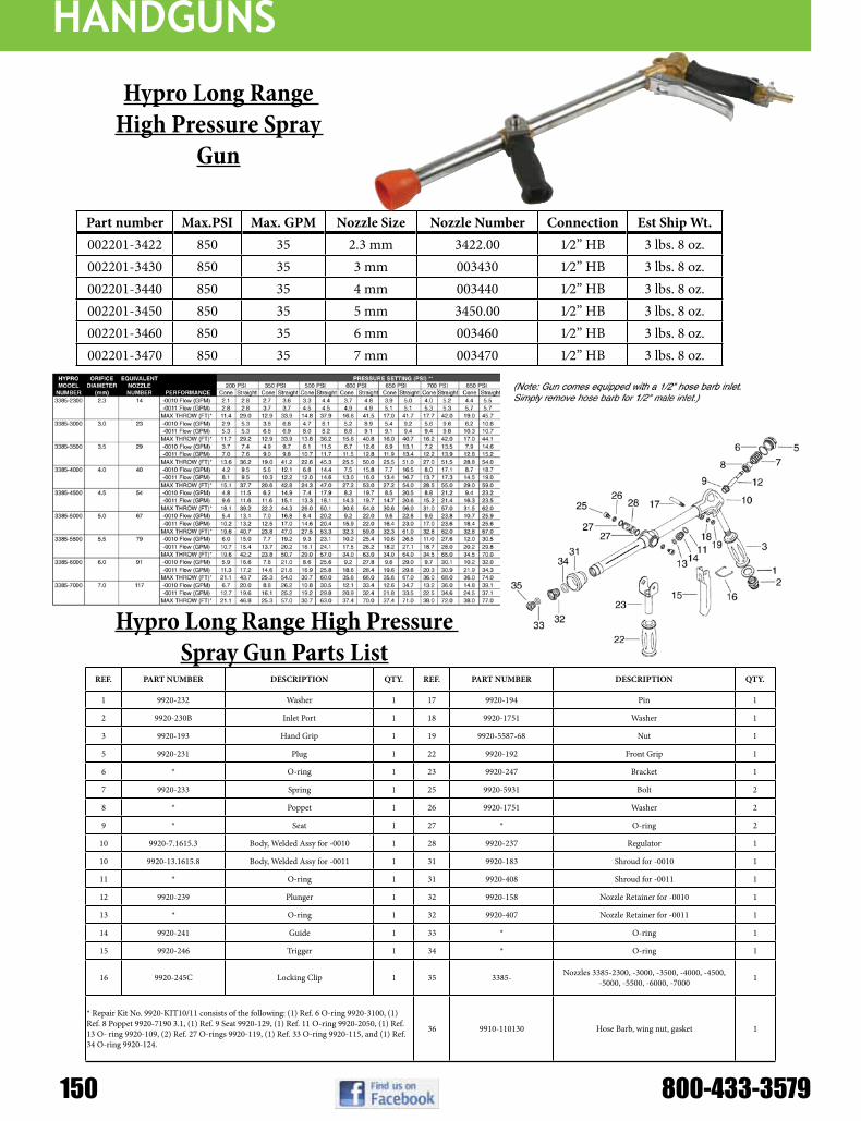
HANDGUNS
150 800-433-3579
Part number Max.PSI Max. GPM Nozzle Size Nozzle Number Connection Est Ship Wt.002201-3422 850 35 2.3 mm 3422.00 1⁄2” HB 3 lbs. 8 oz.002201-3430 850 35 3 mm 003430 1⁄2” HB 3 lbs. 8 oz.002201-3440 850 35 4 mm 003440 1⁄2” HB 3 lbs. 8 oz.002201-3450 850 35 5 mm 3450.00 1⁄2” HB 3 lbs. 8 oz.002201-3460 850 35 6 mm 003460 1⁄2” HB 3 lbs. 8 oz.002201-3470 850 35 7 mm 003470 1⁄2” HB 3 lbs. 8 oz.
Hypro Long Range High Pressure Spray Gun Parts List
Hypro Long Range High Pressure Spray
Gun
REF. PART NUMBER DESCRIPTION QTY. REF. PART NUMBER DESCRIPTION QTY.
1 9920-232 Washer 1 17 9920-194 Pin 1
2 9920-230B Inlet Port 1 18 9920-1751 Washer 1
3 9920-193 Hand Grip 1 19 9920-5587-68 Nut 1
5 9920-231 Plug 1 22 9920-192 Front Grip 1
6 * O-ring 1 23 9920-247 Bracket 1
7 9920-233 Spring 1 25 9920-5931 Bolt 2
8 * Poppet 1 26 9920-1751 Washer 2
9 * Seat 1 27 * O-ring 2
10 9920-7.1615.3 Body, Welded Assy for -0010 1 28 9920-237 Regulator 1
10 9920-13.1615.8 Body, Welded Assy for -0011 1 31 9920-183 Shroud for -0010 1
11 * O-ring 1 31 9920-408 Shroud for -0011 1
12 9920-239 Plunger 1 32 9920-158 Nozzle Retainer for -0010 1
13 * O-ring 1 32 9920-407 Nozzle Retainer for -0011 1
14 9920-241 Guide 1 33 * O-ring 1
15 9920-246 Trigger 1 34 * O-ring 1
16 9920-245C Locking Clip 1 35 3385- Nozzles 3385-2300, -3000, -3500, -4000, -4500, -5000, -5500, -6000, -7000 1
* Repair Kit No. 9920-KIT10/11 consists of the following: (1) Ref. 6 O-ring 9920-3100, (1) Ref. 8 Poppet 9920-7190 3.1, (1) Ref. 9 Seat 9920-129, (1) Ref. 11 O-ring 9920-2050, (1) Ref. 13 O- ring 9920-109, (2) Ref. 27 O-rings 9920-119, (1) Ref. 33 O-ring 9920-115, and (1) Ref. 34 O-ring 9920-124.
36 9910-110130 Hose Barb, wing nut, gasket 1

HANDGUNS
Super Swivel, Part #600401
MediumPressureSteel,NickelPlated.SuperSwivel®canhandle any job and is field greasable. Perfect for Hose Reels. Available in many sizes and configurations.
Male Pipe x Hose BarbAll brass hose barb for connecting hose to other fittings or handguns.
Male Pipe x Female Pipe - SwivelDesigned to swivel up to 1000 psi. No ball bearings to gall or rust. All brass body. Bronze thrust bearing. Available in Buna-N, Ethylene, Propylene, or Fluorocarbon seals.
Part Number End Connec-tion
End Connec-tion Max Pressure Opening Di-
ameter
902-4F4M 1/4 FNPT 1/4 FNPT 1000 0.187900-6F6M 3/8 FNPT 3/8 FNPT 1000 0.312901-8F8M 1/2 FNPT 1/2 FNPT 1000 0.312
Part Number End Connec-tion
End Connec-tion Max Pressure Opening Di-
ameter
902-4M4B 1/4 FNPT 1/4 Barb 1000 0.187900-6M6B 3/8 FNPT 3/8 Barb 1000 0.312901-8M8B 1/2 FNPT 1/2 Barb 1000 0.312
Item # Size Type Port Material Item # Size Type Port Material Item # Size Type Port Material
QC302 1/8” Socket Female Brass QC314S 1/4” Plug Female Steel QC316SS 3/8” Plug Female 303 SS
QC302M 1/8” Socket Male Brass QC314MS 1/4” Plug Male Steel QC316MSS 3/8” Plug Male 303 SS
QC312 1/8” Plug Female Brass QC314SS 1/4” Plug Female 303 SS QC308 1/2” Socket Female Brass
QC312M 1/8” Plug Male Brass QC314MSS 1/4” Plug Male 303 SS QC308M 1/2” Socket Male Brass
QC312S 1/8” Plug Female Steel QC306 3/8” Socket Female Brass QC308S 1/2” Socket Female Steel
QC312MS 1/8” Plug Male Steel QC306M 3/8” Socket Male Brass QC308MS 1/2” Socket Male Steel
QC304 1/4” Socket Female Brass QC306SS 3/8” Socket Female 303 SS QC318 1/2” Plug Female Brass
QC304M 1/4” Socket Male Brass QC306MSS 3/8” Socket Male 303 SS QC318M 1/2” Plug Male Brass
QC304SS 1/4” Socket Female 303 SS QC316 3/8” Plug Female Brass QC318S 1/2” Plug Female Steel
QC304MSS 1/4” Socket Male 303 SS QC316M 3/8” Plug Male Brass QC318MS 1/2” Plug Male Steel
QC314 1/4” Plug Female Brass QC316S 3/8” Plug Female Steel QC318SS 1/2” Plug Female 303 SS
QC314M 1/4” Plug Male Brass QC316MS 3/8” Plug Male Steel QC318MSS 1/2” Plug Male 303 SS
Quick Couplers for Hand Guns
O-ring sealed Quick Disconnects for changing handguns or attachments frequently. All Brass or Galvanized Steel construction. Simple pull down lock collar for ease of use.

boom EquipmEnt
152 800-433-3579
Model Tank Size FrameRMB Series 55 or 85 Gal. 12 ga. steel, Cat I
RM Series 150 or 200 Gal. Cat I & Cat II; Quick-Hitch compatible
RMSE Series 200 or 300 Gal. Cat II; Quick-Hitch compatible
RMLE Series 400 or 500 Gal. Cat II or III; Quick-Hitch compatible
Three-Point MountField Spreaders
Features:• 55-500 gallon Polyethylene tanks• Molded sight gauge• Sump• Fill-well with No-Splash cover• Jet Agitation Standard• Rear mount brackets complete with saddles, tank straps, &
bolts• Compatible with “Quick Attach” 3-point hook-ups• 55 to 500 Gallon• 21’ to 60’ booms• Many control options• Heavy duty formed steel frames• Built-in ground stand for storage when empty• Clean water tank on frame• Category I, II & III models available
Demco Rear Mount / 3-Point Mount Field Sprayers
“DB” Series 6¾’, 12’, & 18’ Booms
Features:• Designed to meet the requirements of lawn and garden spraying.• Horizontal breakaway minimizes needless wear and tear.• Universal mounting brackets provide easy installation.• All hose is 3/8” EPDM chemical resistant rubber.
Model Description
80B25 80” Boom (2 nozzles) (Boom with Plumbing 40” spacing)
DB12B 12’ Boom without Plumbing
DB12 12’ Boom (4 nozzles) (Boom with Plumbing 40” spacing)
DB18B 18’ Boom without Plumbing
DB18 18’ Boom (6 nozzles) (Boom with Plumbing 40” spacing)

boom EquipmEnt
21’, 28’, 30’, & 40’ Truss-T Booms
45’, 50’, & 60’ Hydraulic X-Fold BoomsFeatures:• The hydraulic X-fold boom requires two sets of
remote outlets and has auto level ride and shock-spring flotation.
• Spring loaded cable ride for cushioning and less swing.
• Hydraulic boom wing leveling.• Wings fold independently.• Outer wing breakaway.• Easy access to 3-point pins and hydraulic hookups.• Available in three versions: 3-point tractor mount,
trailer mount or rear mounted tank unit.• Transport width: 10’ 8”• Transport height: 11’ 9” (at a 20” spraying height)• All booms are available with 3/4” high volume
plumbingandTeeJet®dripfreediaphragmchecknozzles with stainless steel boom and hose clamps spaced at 20”.
• Trailer mounts include hydraulic height adjuster (24” travel).
Features:• Designed to meet the requirements of small acreage spraying.• Vertical and horizontal breakaway minimizes needless wear and tear. Eliminates the lashing associated
with a chain boom.• All hose is 1/2” EPDM chemical resistant rubber.• Demco’s Truss-T booms are available on 150, 200 & 300 gallon trailer sprayers and 60, 80, 150 & 200
gallon rear mounts. Feeder lines not included.
Model Description
DB21TB 21’ Truss-T boom (without plumbing) Transport width 8’
DB30TB 30’ Truss-T boom (without plumbing) Transport width 8’
DB40TB 40’ Truss-T boom (without plumbing) Transport width 10’
DB21T 21’ Truss-T boom (13 conventional nozzles) Transport width 8’
DB30T 30’ Truss-T boom (19 conventional nozzles) Transport width 8’
DB40T 40’ Truss-T boom (25 conventional nozzles) Transport width 10’
DB21TDF 21’Truss-Tboom(13TeeJet®dripfreenozzles)Transportwidth8’
DB30TDF 30’Truss-Tboom(19TeeJet®dripfreenozzles)Transportwidth8’
DB40TDF 40’Truss-Tboom(25TeeJet®dripfreenozzles)Transportwidth10’
Model Description
DFB45B 45’ Floating Boom
DFB60B 60’ Floating Boom
DFHY Hydraulic Boom Leveling (for manual fold booms)
DTB3 Mounting Brackets to attach Boom to a tractor’s 3-point hitch (Category II & III)
9416004 Rear Mount Units
9428009 Hydraulic Height Adjuster for trailer and rear mount models (24” travel)
DBTP Wheel Assisted Boom Tip Protectors
9428002 Fence Line Spray Kit, Electric
9428003 Fence Line Spray Kit, Manual

boom EquipmEnt
154 800-433-3579
HerBicideS fuNGicideS iNSecticideS
pre- emerGeNce
poSt-emerGeNce
coNtact SyStemic coNtact SyStemiccoNtact SyStemic
even Reference page 29
eXcelleNt Good eXcelleNt Good eXcelleNt Good eXcelleNt
even
Reference page 31Good very Good Good very Good Good very Good Good
even
Reference page 32
eXcelleNt eXcelleNt eXcelleNt
dir
ecte
d S
pra
yiN
G
even Reference page 29
very Good Good eXcelleNt Good eXcelleNt Good eXcelleNt
even
Reference page 31Good Good Good Good Good Good Good
even
Reference page 32
very Good very Good very Good
Reference page 33Good eXcelleNt Good eXcelleNt Good eXcelleNt
Reference page 38Good eXcelleNt Good eXcelleNt Good eXcelleNt
Reference pages 28 & 35
eXcelleNt eXcelleNt eXcelleNt
air
Bla
St
Reference pages 36–37
eXcelleNt Good eXcelleNt Good eXcelleNt Good
Reference pages 40–41
eXcelleNt Good eXcelleNt Good eXcelleNt Good
Note: Consult the chemical manufacturer’s product label for specific rate and application recommendations.
Specialty application Nozzle Selection GuideBa
Nd
iNG

boom EquipmEnt
Example:Desired application rate is 20 GPA of 28% Nitrogen. Determine the correct nozzle size as follow:
GPA (liquid other than water) x Conversion Factor = GPA (from table in catalog)
20 GPA (28%) x 1.13 = 22.6 GPA (water)
The applicator should choose a nozzle size that will supply 22.6 GPA of water at the desired pressure.
SELECTION GUIDE
broadcast directed
(7-ORIFICE)Reference page 43
eXceLLeNt very Good
(3-ORIFICE)Reference page 42
very Good eXceLLeNt
(Single-ORIFICE)Reference page 45
eXceLLeNt
CP4916 (ORIFICE PLATE)Reference page 44
eXceLLeNt
(LARGE CAPACITY)Reference page 12
very Good
(LOW VOLUME)Reference pages 7–8
very Good
(LOW VOLUME)Reference page 33
very Good
Reference page 9
eXceLLeNt
Reference page 19
eXceLLeNt
Reference page 21
eXceLLeNt
Note: Consult the chemical manufacturer’s product label for specific rate and application recommendations.
Liquid Fertilizer Nozzle selection Guide
LIQUID FERTILIZER APPLICATIONJust as in applying crop protection products, the proper application of liquid fertilizer is important. Delivering nutrients to the crop in a timely and effective manner while minimizing crop damage is essential. TeeJet Technologies offers an extensive selection of nozzles specifically designed to maximize the performance of your liquid fertilizer application.
Solid stream nozzles, offered in both single- and multiple-stream versions, are designed to deliver fertilizer to the soil surface where it can be effectively utilized by the crop. By creating solid liquid streams, these nozzles greatly reduce foliar coverage in standing crop in order to minimize leaf burn. TeeJet Technologies StreamJet nozzles provide the ideal blend of compact, reliable design, ease of installation and affordable pricing.
In some cases, the use of a broadcast nozzle for fertilizer application may be desirable. This could include combined fertilizer/pesticide applications, foliar feeding or broadcast liquid fertilization of bare ground. For these applications TeeJet Technologies offers a wide variety of low drift, flat spray nozzles.
Liquid Density ConversionWhen selecting a specific capacity tip for liquid fertilizer application, always correct for liquid density. Application charts shown in this catalog are based on spraying water. Many fertilizer solutions are denser than water, which will affect the application rate. Please see page 125 for a list of density conversion factors.

boom EquipmEnt
156 800-433-35795
110°
209
209
psi
Dropsize
capacity one
nozzlein GpM
capacity one
nozzlein
oz./Min.
209
gpa gallons per 1000 sq. ft.4 mph 5 mph 6 mph 8 mph 10 mph 12 mph 15 mph 20 mph 2 mph 3 mph 4 mph 5 mph
tt11001 (100)
15 C 0.061 7.8 4.5 3.6 3.0 2.3 1.8 1.5 1.2 0.91 0.21 0.14 0.10 0.0820 M 0.071 9.1 5.3 4.2 3.5 2.6 2.1 1.8 1.4 1.1 0.24 0.16 0.12 0.1030 M 0.087 11 6.5 5.2 4.3 3.2 2.6 2.2 1.7 1.3 0.30 0.20 0.15 0.1240 M 0.10 13 7.4 5.9 5.0 3.7 3.0 2.5 2.0 1.5 0.34 0.23 0.17 0.1450 F 0.11 14 8.2 6.5 5.4 4.1 3.3 2.7 2.2 1.6 0.37 0.25 0.19 0.1560 F 0.12 15 8.9 7.1 5.9 4.5 3.6 3.0 2.4 1.8 0.41 0.27 0.20 0.1675 F 0.14 18 10.4 8.3 6.9 5.2 4.2 3.5 2.8 2.1 0.48 0.32 0.24 0.1990 F 0.15 19 11.1 8.9 7.4 5.6 4.5 3.7 3.0 2.2 0.51 0.34 0.26 0.20
tt110015 (100)
15 C 0.092 12 6.8 5.5 4.6 3.4 2.7 2.3 1.8 1.4 0.31 0.21 0.16 0.1320 C 0.11 14 8.2 6.5 5.4 4.1 3.3 2.7 2.2 1.6 0.37 0.25 0.19 0.1530 M 0.13 17 9.7 7.7 6.4 4.8 3.9 3.2 2.6 1.9 0.44 0.29 0.22 0.1840 M 0.15 19 11.1 8.9 7.4 5.6 4.5 3.7 3.0 2.2 0.51 0.34 0.26 0.2050 M 0.17 22 12.6 10.1 8.4 6.3 5.0 4.2 3.4 2.5 0.58 0.39 0.29 0.2360 M 0.18 23 13.4 10.7 8.9 6.7 5.3 4.5 3.6 2.7 0.61 0.41 0.31 0.2475 F 0.21 27 15.6 12.5 10.4 7.8 6.2 5.2 4.2 3.1 0.71 0.48 0.36 0.2990 F 0.23 29 17.1 13.7 11.4 8.5 6.8 5.7 4.6 3.4 0.78 0.52 0.39 0.31
tt11002 (50)
15 C 0.12 15 8.9 7.1 5.9 4.5 3.6 3.0 2.4 1.8 0.41 0.27 0.20 0.1620 C 0.14 18 10.4 8.3 6.9 5.2 4.2 3.5 2.8 2.1 0.48 0.32 0.24 0.1930 M 0.17 22 12.6 10.1 8.4 6.3 5.0 4.2 3.4 2.5 0.58 0.39 0.29 0.2340 M 0.20 26 14.9 11.9 9.9 7.4 5.9 5.0 4.0 3.0 0.68 0.45 0.34 0.2750 M 0.22 28 16.3 13.1 10.9 8.2 6.5 5.4 4.4 3.3 0.75 0.50 0.37 0.3060 M 0.24 31 17.8 14.3 11.9 8.9 7.1 5.9 4.8 3.6 0.82 0.54 0.41 0.3375 M 0.27 35 20 16.0 13.4 10.0 8.0 6.7 5.3 4.0 0.92 0.61 0.46 0.3790 F 0.30 38 22 17.8 14.9 11.1 8.9 7.4 5.9 4.5 1.0 0.68 0.51 0.41
tt110025 (50)
15 VC 0.15 19 11.1 8.9 7.4 5.6 4.5 3.7 3.0 2.2 0.51 0.34 0.26 0.2020 C 0.18 23 13.4 10.7 8.9 6.7 5.3 4.5 3.6 2.7 0.61 0.41 0.31 0.2430 C 0.22 28 16.3 13.1 10.9 8.2 6.5 5.4 4.4 3.3 0.75 0.50 0.37 0.3040 M 0.25 32 18.6 14.9 12.4 9.3 7.4 6.2 5.0 3.7 0.85 0.57 0.43 0.3450 M 0.28 36 21 16.6 13.9 10.4 8.3 6.9 5.5 4.2 0.95 0.63 0.48 0.3860 M 0.31 40 23 18.4 15.3 11.5 9.2 7.7 6.1 4.6 1.1 0.70 0.53 0.4275 M 0.34 44 25 20 16.8 12.6 10.1 8.4 6.7 5.0 1.2 0.77 0.58 0.4690 F 0.38 49 28 23 18.8 14.1 11.3 9.4 7.5 5.6 1.3 0.86 0.65 0.52
tt11003 (50)
15 VC 0.18 23 13.4 10.7 8.9 6.7 5.3 4.5 3.6 2.7 0.61 0.41 0.31 0.2420 VC 0.21 27 15.6 12.5 10.4 7.8 6.2 5.2 4.2 3.1 0.71 0.48 0.36 0.2930 C 0.26 33 19.3 15.4 12.9 9.7 7.7 6.4 5.1 3.9 0.88 0.59 0.44 0.3540 C 0.30 38 22 17.8 14.9 11.1 8.9 7.4 5.9 4.5 1.0 0.68 0.51 0.4150 M 0.34 44 25 20 16.8 12.6 10.1 8.4 6.7 5.0 1.2 0.77 0.58 0.4660 M 0.37 47 27 22 18.3 13.7 11.0 9.2 7.3 5.5 1.3 0.84 0.63 0.5075 M 0.41 52 30 24 20 15.2 12.2 10.1 8.1 6.1 1.4 0.93 0.70 0.5690 M 0.45 58 33 27 22 16.7 13.4 11.1 8.9 6.7 1.5 1.0 0.77 0.61
tt11004 (50)
15 XC 0.24 31 17.8 14.3 11.9 8.9 7.1 5.9 4.8 3.6 0.82 0.54 0.41 0.3320 VC 0.28 36 21 16.6 13.9 10.4 8.3 6.9 5.5 4.2 0.95 0.63 0.48 0.3830 C 0.35 45 26 21 17.3 13.0 10.4 8.7 6.9 5.2 1.2 0.79 0.60 0.4840 C 0.40 51 30 24 19.8 14.9 11.9 9.9 7.9 5.9 1.4 0.91 0.68 0.5450 C 0.45 58 33 27 22 16.7 13.4 11.1 8.9 6.7 1.5 1.0 0.77 0.6160 C 0.49 63 36 29 24 18.2 14.6 12.1 9.7 7.3 1.7 1.1 0.83 0.6775 M 0.55 70 41 33 27 20 16.3 13.6 10.9 8.2 1.9 1.2 0.94 0.7590 M 0.60 77 45 36 30 22 17.8 14.9 11.9 8.9 2.0 1.4 1.0 0.82
tt11005 (50)
15 XC 0.31 40 23 18.4 15.3 11.5 9.2 7.7 6.1 4.6 1.1 0.70 0.53 0.4220 VC 0.35 45 26 21 17.3 13.0 10.4 8.7 6.9 5.2 1.2 0.79 0.60 0.4830 VC 0.43 55 32 26 21 16.0 12.8 10.6 8.5 6.4 1.5 0.97 0.73 0.5840 C 0.50 64 37 30 25 18.6 14.9 12.4 9.9 7.4 1.7 1.1 0.85 0.6850 C 0.56 72 42 33 28 21 16.6 13.9 11.1 8.3 1.9 1.3 0.95 0.7660 C 0.61 78 45 36 30 23 18.1 15.1 12.1 9.1 2.1 1.4 1.0 0.8375 C 0.68 87 50 40 34 25 20 16.8 13.5 10.1 2.3 1.5 1.2 0.9290 M 0.75 96 56 45 37 28 22 18.6 14.9 11.1 2.6 1.7 1.3 1.0
tt11006 (50)
15 XC 0.37 47 27 22 18.3 13.7 11.0 9.2 7.3 5.5 1.3 0.84 0.63 0.5020 XC 0.42 54 31 25 21 15.6 12.5 10.4 8.3 6.2 1.4 0.95 0.71 0.5730 VC 0.52 67 39 31 26 19.3 15.4 12.9 10.3 7.7 1.8 1.2 0.88 0.7140 C 0.60 77 45 36 30 22 17.8 14.9 11.9 8.9 2.0 1.4 1.0 0.8250 C 0.67 86 50 40 33 25 19.9 16.6 13.3 9.9 2.3 1.5 1.1 0.9160 C 0.73 93 54 43 36 27 22 18.1 14.5 10.8 2.5 1.7 1.2 0.9975 C 0.82 105 61 49 41 30 24 20 16.2 12.2 2.8 1.9 1.4 1.190 M 0.90 115 67 53 45 33 27 22 17.8 13.4 3.1 2.0 1.5 1.2
tt11008 (50)
15 XC 0.49 63 36 29 24 18.2 14.6 12.1 9.7 7.3 1.7 1.1 0.83 0.6720 XC 0.57 73 42 34 28 21 16.9 14.1 11.3 8.5 1.9 1.3 0.97 0.7830 VC 0.69 88 51 41 34 26 20 17.1 13.7 10.2 2.3 1.6 1.2 0.9440 VC 0.80 102 59 48 40 30 24 19.8 15.8 11.9 2.7 1.8 1.4 1.150 C 0.89 114 66 53 44 33 26 22 17.6 13.2 3.0 2.0 1.5 1.260 C 0.98 125 73 58 49 36 29 24 19.4 14.6 3.3 2.2 1.7 1.375 C 1.10 141 82 65 54 41 33 27 22 16.3 3.7 2.5 1.9 1.590 M 1.20 154 89 71 59 45 36 30 24 17.8 4.1 2.7 2.0 1.6
BROADCAST NOZZLES
Wide angle flat spray tips
Typical Applications:See selection guide on page 2 for recommended typical applications for Turbo TeeJet tips.
Features:n Tapered edge wide angle flat spray pattern
for uniform coverage in broadcast spraying.n Large, rounded internal passage to
minimize clogging.n Excellent resistance to corrosive solutions.n Superior wear characteristics.n Larger droplets for less drift—
15–90 PSI (1–6 bar).
n Automatic spray alignment with 25612-*-NYR Quick TeeJet® cap and gasket. Reference page 57 for more information.
n Blockage-free passage means less clogging.
n Unique internal configuration means substantially longer wear life.
how to order: Specify tip number.
Example: TT11001-VP – Polymer with VisiFlo®
color-codingnote: Always double check your application rates. Tabulations are based on spraying water at 70°F (21°C). See pages 124–140 for drop size classification, useful formulas and other information.
Spacing
SprayHeight
optimum spray height
ContaCtproDuCt
sYstemiCproDuCt
Driftmanagement
VerY gooD VerY gooD VerY gooD
gooD* eXCellent* VerY gooD*
*At pressures below 30 PSI (2.0 bar)

boom EquipmEnt
110°
209
209
psi
Dropsize
capacity one
nozzlein GpM
capacity one
nozzlein
oz./Min.
209
gpa gallons per 1000 sq. ft.
4 mph 5 mph 6 mph 8 mph 10 mph 12 mph 15 mph 20 mph 2 mph 3 mph 4 mph 5 mph
aiC110015 (100)
30 UC 0.13 17 9.7 7.7 6.4 4.8 3.9 3.2 2.6 1.9 0.44 0.29 0.22 0.1840 XC 0.15 19 11.1 8.9 7.4 5.6 4.5 3.7 3.0 2.2 0.51 0.34 0.26 0.2050 XC 0.17 22 12.6 10.1 8.4 6.3 5.0 4.2 3.4 2.5 0.58 0.39 0.29 0.2360 VC 0.18 23 13.4 10.7 8.9 6.7 5.3 4.5 3.6 2.7 0.61 0.41 0.31 0.2470 VC 0.20 26 14.9 11.9 9.9 7.4 5.9 5.0 4.0 3.0 0.68 0.45 0.34 0.2780 VC 0.21 27 15.6 12.5 10.4 7.8 6.2 5.2 4.2 3.1 0.71 0.48 0.36 0.2990 C 0.23 29 17.1 13.7 11.4 8.5 6.8 5.7 4.6 3.4 0.78 0.52 0.39 0.31
100 C 0.24 31 17.8 14.3 11.9 8.9 7.1 5.9 4.8 3.6 0.82 0.54 0.41 0.33
aiC11002 (50)
30 UC 0.17 22 12.6 10.1 8.4 6.3 5.0 4.2 3.4 2.5 0.58 0.39 0.29 0.2340 XC 0.20 26 14.9 11.9 9.9 7.4 5.9 5.0 4.0 3.0 0.68 0.45 0.34 0.2750 XC 0.22 28 16.3 13.1 10.9 8.2 6.5 5.4 4.4 3.3 0.75 0.50 0.37 0.3060 VC 0.24 31 17.8 14.3 11.9 8.9 7.1 5.9 4.8 3.6 0.82 0.54 0.41 0.3370 VC 0.26 33 19.3 15.4 12.9 9.7 7.7 6.4 5.1 3.9 0.88 0.59 0.44 0.3580 VC 0.28 36 21 16.6 13.9 10.4 8.3 6.9 5.5 4.2 1.0 0.63 0.48 0.3890 VC 0.30 38 22 17.8 14.9 11.1 8.9 7.4 5.9 4.5 1.0 0.68 0.51 0.41
100 C 0.32 41 24 19.0 15.8 11.9 9.5 7.9 6.3 4.8 1.1 0.73 0.54 0.44
aiC110025 (50)
30 UC 0.22 28 16.3 13.1 10.9 8.2 6.5 5.4 4.4 3.3 0.75 0.50 0.37 0.3040 XC 0.25 32 18.6 14.9 12.4 9.3 7.4 6.2 5.0 3.7 0.85 0.57 0.43 0.3450 XC 0.28 36 21 16.6 13.9 10.4 8.3 6.9 5.5 4.2 0.95 0.63 0.48 0.3860 XC 0.31 40 23 18.4 15.3 11.5 9.2 7.7 6.1 4.6 1.1 0.70 0.53 0.4270 VC 0.33 42 25 19.6 16.3 12.3 9.8 8.2 6.5 4.9 1.1 0.75 0.56 0.4580 VC 0.35 45 26 21 17.3 13.0 10.4 8.7 6.9 5.2 1.2 0.79 0.60 0.4890 VC 0.38 49 28 23 18.8 14.1 11.3 9.4 7.5 5.6 1.3 0.86 0.65 0.52
100 C 0.40 51 30 24 19.8 14.9 11.9 9.9 7.9 5.9 1.4 0.91 0.68 0.54
aiC11003 (50)
30 UC 0.26 33 19.3 15.4 12.9 9.7 7.7 6.4 5.1 3.9 0.88 0.59 0.44 0.3540 XC 0.30 38 22 17.8 14.9 11.1 8.9 7.4 5.9 4.5 1.0 0.68 0.51 0.4150 XC 0.34 44 25 20 16.8 12.6 10.1 8.4 6.7 5.0 1.2 0.77 0.58 0.4660 XC 0.37 47 27 22 18.3 13.7 11.0 9.2 7.3 5.5 1.3 0.84 0.63 0.5070 VC 0.40 51 30 24 19.8 14.9 11.9 9.9 7.9 5.9 1.4 0.91 0.68 0.5480 VC 0.42 54 31 25 21 15.6 12.5 10.4 8.3 6.2 1.4 0.95 0.71 0.5790 VC 0.45 58 33 27 22 16.7 13.4 11.1 8.9 6.7 1.5 1.0 0.77 0.61
100 C 0.47 60 35 28 23 17.4 14.0 11.6 9.3 7.0 1.6 1.1 0.80 0.64
aiC11004 (50)
30 UC 0.35 45 26 21 17.3 13.0 10.4 8.7 6.9 5.2 1.2 0.79 0.60 0.4840 XC 0.40 51 30 24 19.8 14.9 11.9 9.9 7.9 5.9 1.4 0.91 0.68 0.5450 XC 0.45 58 33 27 22 16.7 13.4 11.1 8.9 6.7 1.5 1.0 0.77 0.6160 XC 0.49 63 36 29 24 18.2 14.6 12.1 9.7 7.3 1.7 1.1 0.83 0.6770 VC 0.53 68 39 31 26 19.7 15.7 13.1 10.5 7.9 1.8 1.2 0.90 0.7280 VC 0.57 73 42 34 28 21 16.9 14.1 11.3 8.5 1.9 1.3 0.97 0.7890 VC 0.60 77 45 36 30 22 17.8 14.9 11.9 8.9 2.0 1.4 1.0 0.82
100 C 0.63 81 47 37 31 23 18.7 15.6 12.5 9.4 2.1 1.4 1.1 0.86
aiC11005 (50)
30 UC 0.43 55 32 26 21 16.0 12.8 10.6 8.5 6.4 1.5 0.97 0.73 0.5840 XC 0.50 64 37 30 25 18.6 14.9 12.4 9.9 7.4 1.7 1.1 0.85 0.6850 XC 0.56 72 42 33 28 21 16.6 13.9 11.1 8.3 1.9 1.3 0.95 0.7660 XC 0.61 78 45 36 30 23 18.1 15.1 12.1 9.1 2.1 1.4 1.0 0.8370 VC 0.66 84 49 39 33 25 19.6 16.3 13.1 9.8 2.2 1.5 1.1 0.9080 VC 0.71 91 53 42 35 26 21 17.6 14.1 10.5 2.4 1.6 1.2 0.9790 VC 0.75 96 56 45 37 28 22 18.6 14.9 11.1 2.6 1.7 1.3 1.0
100 VC 0.79 101 59 47 39 29 23 19.6 15.6 11.7 2.7 1.8 1.3 1.1
aiC11006 (50)
30 UC 0.52 67 39 31 26 19.3 15.4 12.9 10.3 7.7 1.8 1.2 0.88 0.7140 UC 0.60 77 45 36 30 22 17.8 14.9 11.9 8.9 2.0 1.4 1.0 0.8250 XC 0.67 86 50 40 33 25 19.9 16.6 13.3 9.9 2.3 1.5 1.1 0.9160 XC 0.73 93 54 43 36 27 22 18.1 14.5 10.8 2.5 1.7 1.2 0.9970 XC 0.79 101 59 47 39 29 23 19.6 15.6 11.7 2.7 1.8 1.3 1.180 VC 0.85 109 63 50 42 32 25 21 16.8 12.6 2.9 1.9 1.4 1.290 VC 0.90 115 67 53 45 33 27 22 17.8 13.4 3.1 2.0 1.5 1.2
100 VC 0.95 122 71 56 47 35 28 24 18.8 14.1 3.2 2.2 1.6 1.3
aiC11008 (50)
30 UC 0.69 88 51 41 34 26 20 17.1 13.7 10.2 2.3 1.6 1.2 0.9440 UC 0.80 102 59 48 40 30 24 19.8 15.8 11.9 2.7 1.8 1.4 1.150 XC 0.89 114 66 53 44 33 26 22 17.6 13.2 3.0 2.0 1.5 1.260 XC 0.98 125 73 58 49 36 29 24 19.4 14.6 3.3 2.2 1.7 1.370 XC 1.06 136 79 63 52 39 31 26 21 15.7 3.6 2.4 1.8 1.480 VC 1.13 145 84 67 56 42 34 28 22 16.8 3.8 2.6 1.9 1.590 VC 1.20 154 89 71 59 45 36 30 24 17.8 4.1 2.7 2.0 1.6
100 VC 1.26 161 94 75 62 47 37 31 25 18.7 4.3 2.9 2.1 1.7
aiC11010
30 UC 0.87 111 65 52 43 32 26 22 17.2 12.9 3.0 2.0 1.5 1.240 UC 1.00 128 74 59 50 37 30 25 19.8 14.9 3.4 2.3 1.7 1.450 XC 1.12 143 83 67 55 42 33 28 22 16.6 3.8 2.5 1.9 1.560 XC 1.22 156 91 72 60 45 36 30 24 18.1 4.1 2.8 2.1 1.770 XC 1.32 169 98 78 65 49 39 33 26 19.6 4.5 3.0 2.2 1.880 XC 1.41 180 105 84 70 52 42 35 28 21 4.8 3.2 2.4 1.990 VC 1.50 192 111 89 74 56 45 37 30 22 5.1 3.4 2.6 2.0
100 VC 1.58 202 117 94 78 59 47 39 31 23 5.4 3.6 2.7 2.1
aiC11015
30 UC 1.30 166 97 77 64 48 39 32 26 19.3 4.4 2.9 2.2 1.840 UC 1.50 192 111 89 74 56 45 37 30 22 5.1 3.4 2.6 2.050 XC 1.68 215 125 100 83 62 50 42 33 25 5.7 3.8 2.9 2.360 XC 1.84 236 137 109 91 68 55 46 36 27 6.3 4.2 3.1 2.570 XC 1.98 253 147 118 98 74 59 49 39 29 6.7 4.5 3.4 2.780 XC 2.12 271 157 126 105 79 63 52 42 31 7.2 4.8 3.6 2.990 VC 2.25 288 167 134 111 84 67 56 45 33 7.7 5.1 3.8 3.1
100 VC 2.37 303 176 141 117 88 70 59 47 35 8.1 5.4 4.0 3.2
note: Due to the pre-orifice design, this tip is not compatible with the 4193A check valve tip strainer.
Typical Applications:See selection guide on page 2 for recommended typical applications for AIC TeeJet tips.
Features:n Produces a 110° tapered edge flat
spray pattern for uniform coverage in broadcast spraying applications.
n Available with a polymer insert holder with stainless steel (015–15 capacities), ceramic (025–05 capacities) or polymer (02–10 capacities) inserts.
n Larger droplets for less drift.n Depending on the chemical,
produces large air-filled drops through the use of a Venturi air aspirator.
n AI TeeJet nozzle molded into Quick TeeJet® cap provides automatic spray alignment.
n Includes tightly fitting washer that stays put and assures a good seal.
n Recommended pressure rating 30–115 PSI (2–8 bar).
how to order:Specify tip number.
Examples: AIC11004-VS – Stainless Steel
with VisiFlo® color-coding
AIC11003-VP – Polymer with VisiFlo color-coding
AIC11003-VK – Ceramic with VisiFlo color-coding
air induction flat spray tips
BROADCAST NOZZLES
Spacing
Spray Height
optimum spray height
ContaCtproDuCt
sYstemiCproDuCt
Driftmanagement
gooD eXCellent eXCellent
note: Always double check your application rates. Tabulations are based on spraying water at 70°F (21°C). See pages 124–140 for drop size classification, useful formulas and other information.
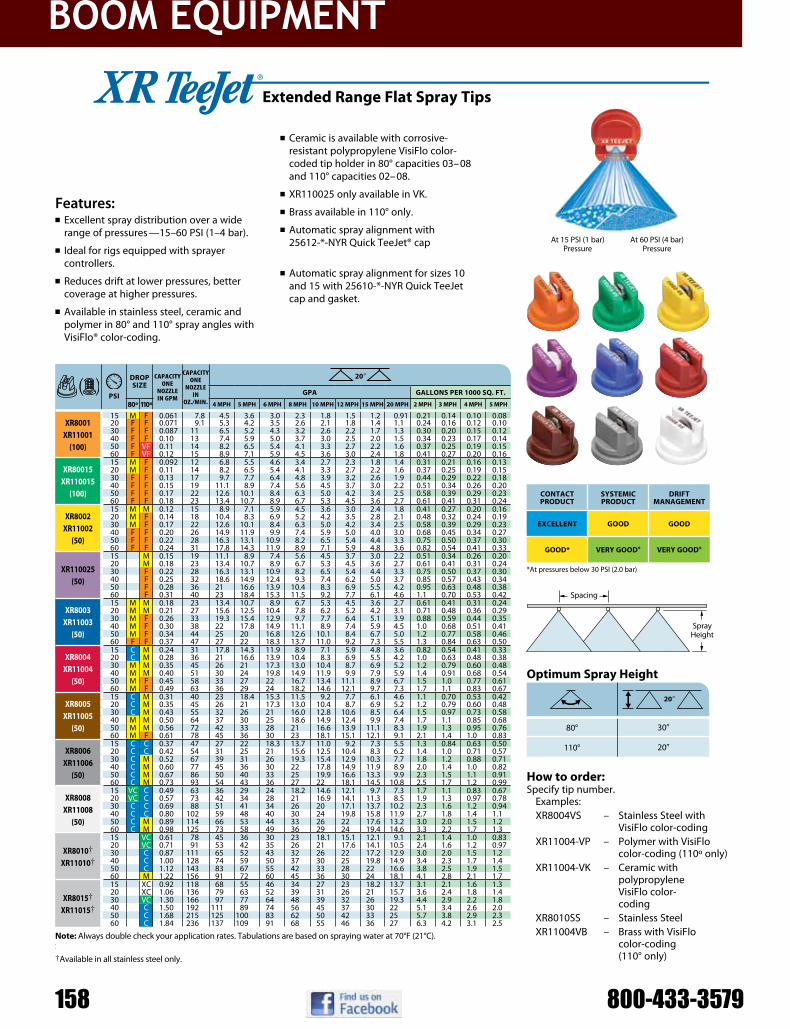
boom EquipmEnt
158 800-433-357910
80°
110°
209
309
209
psi
Dropsize
capacity one
nozzlein GpM
capacity one
nozzlein
oz./Min.
209
gpa gallons per 1000 sq. ft.
80º 110º 4 mph 5 mph 6 mph 8 mph 10 mph 12 mph 15 mph 20 mph 2 mph 3 mph 4 mph 5 mph
Xr8001 Xr11001
(100)
15 M F 0.061 7.8 4.5 3.6 3.0 2.3 1.8 1.5 1.2 0.91 0.21 0.14 0.10 0.0820 F F 0.071 9.1 5.3 4.2 3.5 2.6 2.1 1.8 1.4 1.1 0.24 0.16 0.12 0.1030 F F 0.087 11 6.5 5.2 4.3 3.2 2.6 2.2 1.7 1.3 0.30 0.20 0.15 0.1240 F F 0.10 13 7.4 5.9 5.0 3.7 3.0 2.5 2.0 1.5 0.34 0.23 0.17 0.1450 F VF 0.11 14 8.2 6.5 5.4 4.1 3.3 2.7 2.2 1.6 0.37 0.25 0.19 0.1560 F VF 0.12 15 8.9 7.1 5.9 4.5 3.6 3.0 2.4 1.8 0.41 0.27 0.20 0.16
Xr80015 Xr110015
(100)
15 M F 0.092 12 6.8 5.5 4.6 3.4 2.7 2.3 1.8 1.4 0.31 0.21 0.16 0.1320 M F 0.11 14 8.2 6.5 5.4 4.1 3.3 2.7 2.2 1.6 0.37 0.25 0.19 0.1530 F F 0.13 17 9.7 7.7 6.4 4.8 3.9 3.2 2.6 1.9 0.44 0.29 0.22 0.1840 F F 0.15 19 11.1 8.9 7.4 5.6 4.5 3.7 3.0 2.2 0.51 0.34 0.26 0.2050 F F 0.17 22 12.6 10.1 8.4 6.3 5.0 4.2 3.4 2.5 0.58 0.39 0.29 0.2360 F F 0.18 23 13.4 10.7 8.9 6.7 5.3 4.5 3.6 2.7 0.61 0.41 0.31 0.24
Xr8002 Xr11002
(50)
15 M M 0.12 15 8.9 7.1 5.9 4.5 3.6 3.0 2.4 1.8 0.41 0.27 0.20 0.1620 M F 0.14 18 10.4 8.3 6.9 5.2 4.2 3.5 2.8 2.1 0.48 0.32 0.24 0.1930 M F 0.17 22 12.6 10.1 8.4 6.3 5.0 4.2 3.4 2.5 0.58 0.39 0.29 0.2340 F F 0.20 26 14.9 11.9 9.9 7.4 5.9 5.0 4.0 3.0 0.68 0.45 0.34 0.2750 F F 0.22 28 16.3 13.1 10.9 8.2 6.5 5.4 4.4 3.3 0.75 0.50 0.37 0.3060 F F 0.24 31 17.8 14.3 11.9 8.9 7.1 5.9 4.8 3.6 0.82 0.54 0.41 0.33
Xr110025 (50)
15 M 0.15 19 11.1 8.9 7.4 5.6 4.5 3.7 3.0 2.2 0.51 0.34 0.26 0.2020 M 0.18 23 13.4 10.7 8.9 6.7 5.3 4.5 3.6 2.7 0.61 0.41 0.31 0.2430 F 0.22 28 16.3 13.1 10.9 8.2 6.5 5.4 4.4 3.3 0.75 0.50 0.37 0.3040 F 0.25 32 18.6 14.9 12.4 9.3 7.4 6.2 5.0 3.7 0.85 0.57 0.43 0.3450 F 0.28 36 21 16.6 13.9 10.4 8.3 6.9 5.5 4.2 0.95 0.63 0.48 0.3860 F 0.31 40 23 18.4 15.3 11.5 9.2 7.7 6.1 4.6 1.1 0.70 0.53 0.42
Xr8003 Xr11003
(50)
15 M M 0.18 23 13.4 10.7 8.9 6.7 5.3 4.5 3.6 2.7 0.61 0.41 0.31 0.2420 M M 0.21 27 15.6 12.5 10.4 7.8 6.2 5.2 4.2 3.1 0.71 0.48 0.36 0.2930 M F 0.26 33 19.3 15.4 12.9 9.7 7.7 6.4 5.1 3.9 0.88 0.59 0.44 0.3540 M F 0.30 38 22 17.8 14.9 11.1 8.9 7.4 5.9 4.5 1.0 0.68 0.51 0.4150 M F 0.34 44 25 20 16.8 12.6 10.1 8.4 6.7 5.0 1.2 0.77 0.58 0.4660 F F 0.37 47 27 22 18.3 13.7 11.0 9.2 7.3 5.5 1.3 0.84 0.63 0.50
Xr8004 Xr11004
(50)
15 C M 0.24 31 17.8 14.3 11.9 8.9 7.1 5.9 4.8 3.6 0.82 0.54 0.41 0.3320 C M 0.28 36 21 16.6 13.9 10.4 8.3 6.9 5.5 4.2 1.0 0.63 0.48 0.3830 M M 0.35 45 26 21 17.3 13.0 10.4 8.7 6.9 5.2 1.2 0.79 0.60 0.4840 M M 0.40 51 30 24 19.8 14.9 11.9 9.9 7.9 5.9 1.4 0.91 0.68 0.5450 M F 0.45 58 33 27 22 16.7 13.4 11.1 8.9 6.7 1.5 1.0 0.77 0.6160 M F 0.49 63 36 29 24 18.2 14.6 12.1 9.7 7.3 1.7 1.1 0.83 0.67
Xr8005 Xr11005
(50)
15 C M 0.31 40 23 18.4 15.3 11.5 9.2 7.7 6.1 4.6 1.1 0.70 0.53 0.4220 C M 0.35 45 26 21 17.3 13.0 10.4 8.7 6.9 5.2 1.2 0.79 0.60 0.4830 C M 0.43 55 32 26 21 16.0 12.8 10.6 8.5 6.4 1.5 0.97 0.73 0.5840 M M 0.50 64 37 30 25 18.6 14.9 12.4 9.9 7.4 1.7 1.1 0.85 0.6850 M M 0.56 72 42 33 28 21 16.6 13.9 11.1 8.3 1.9 1.3 0.95 0.7660 M F 0.61 78 45 36 30 23 18.1 15.1 12.1 9.1 2.1 1.4 1.0 0.83
Xr8006 Xr11006
(50)
15 C C 0.37 47 27 22 18.3 13.7 11.0 9.2 7.3 5.5 1.3 0.84 0.63 0.5020 C C 0.42 54 31 25 21 15.6 12.5 10.4 8.3 6.2 1.4 1.0 0.71 0.5730 C M 0.52 67 39 31 26 19.3 15.4 12.9 10.3 7.7 1.8 1.2 0.88 0.7140 C M 0.60 77 45 36 30 22 17.8 14.9 11.9 8.9 2.0 1.4 1.0 0.8250 C M 0.67 86 50 40 33 25 19.9 16.6 13.3 9.9 2.3 1.5 1.1 0.9160 C M 0.73 93 54 43 36 27 22 18.1 14.5 10.8 2.5 1.7 1.2 0.99
Xr8008 Xr11008
(50)
15 VC C 0.49 63 36 29 24 18.2 14.6 12.1 9.7 7.3 1.7 1.1 0.83 0.6720 VC C 0.57 73 42 34 28 21 16.9 14.1 11.3 8.5 1.9 1.3 0.97 0.7830 C C 0.69 88 51 41 34 26 20 17.1 13.7 10.2 2.3 1.6 1.2 0.9440 C C 0.80 102 59 48 40 30 24 19.8 15.8 11.9 2.7 1.8 1.4 1.150 C M 0.89 114 66 53 44 33 26 22 17.6 13.2 3.0 2.0 1.5 1.260 C M 0.98 125 73 58 49 36 29 24 19.4 14.6 3.3 2.2 1.7 1.3
Xr8010† Xr11010†
15 VC 0.61 78 45 36 30 23 18.1 15.1 12.1 9.1 2.1 1.4 1.0 0.8320 VC 0.71 91 53 42 35 26 21 17.6 14.1 10.5 2.4 1.6 1.2 0.9730 C 0.87 111 65 52 43 32 26 22 17.2 12.9 3.0 2.0 1.5 1.240 C 1.00 128 74 59 50 37 30 25 19.8 14.9 3.4 2.3 1.7 1.450 C 1.12 143 83 67 55 42 33 28 22 16.6 3.8 2.5 1.9 1.560 M 1.22 156 91 72 60 45 36 30 24 18.1 4.1 2.8 2.1 1.7
Xr8015† Xr11015†
15 XC 0.92 118 68 55 46 34 27 23 18.2 13.7 3.1 2.1 1.6 1.320 XC 1.06 136 79 63 52 39 31 26 21 15.7 3.6 2.4 1.8 1.430 VC 1.30 166 97 77 64 48 39 32 26 19.3 4.4 2.9 2.2 1.840 C 1.50 192 111 89 74 56 45 37 30 22 5.1 3.4 2.6 2.050 C 1.68 215 125 100 83 62 50 42 33 25 5.7 3.8 2.9 2.360 C 1.84 236 137 109 91 68 55 46 36 27 6.3 4.2 3.1 2.5
At 15 PSI (1 bar) Pressure
At 60 PSI (4 bar) Pressure
Typical Applications:See selection guide on page 2 for recommended typical applications for XR TeeJet tips.
Features:n Excellent spray distribution over a wide
range of pressures—15–60 PSI (1–4 bar).
n Ideal for rigs equipped with sprayer controllers.
n Reduces drift at lower pressures, better coverage at higher pressures.
n Available in stainless steel, ceramic and polymer in 80° and 110° spray angles with VisiFlo® color-coding.
n Ceramic is available with corrosive- resistant polypropylene VisiFlo color- coded tip holder in 80° capacities 03–08 and 110° capacities 02–08.
n XR110025 only available in VK.
n Brass available in 110° only.
n Automatic spray alignment with 25612-*-NYR Quick TeeJet® cap and gasket. Reference page 57 for more information.
n Automatic spray alignment for sizes 10 and 15 with 25610-*-NYR Quick TeeJet cap and gasket. Reference page 57 for more information.
optimum spray height
how to order:Specify tip number.
Examples: XR8004VS – Stainless Steel with
VisiFlo color-coding XR11004-VP – Polymer with VisiFlo
color-coding (110º only) XR11004-VK – Ceramic with
polypropylene VisiFlo color- coding
XR8010SS – Stainless Steel XR11004VB – Brass with VisiFlo
color-coding (110° only)
extended range flat spray tips
BROADCAST NOZZLES
Spacing
Spray Height
ContaCtproDuCt
sYstemiCproDuCt
Driftmanagement
eXCellent gooD gooD
gooD* VerY gooD* VerY gooD*
*At pressures below 30 PSI (2.0 bar)
note: Always double check your application rates. Tabulations are based on spraying water at 70°F (21°C). See pages 124–140 for drop size classification, useful formulas and other information.†Available in all stainless steel only.

boom EquipmEnt
110°
psi
Dropsize
capacity one
nozzlein GpM
capacity one
nozzlein
oz./Min.
209
gpa gallons per 1000 sq. ft.
4 mph 5 mph 6 mph 8 mph 10 mph 12 mph 15 mph 20 mph 2 mph 3 mph 4 mph 5 mph
aiXr110015 (100)
15 XC 0.092 12 6.8 5.5 4.6 3.4 2.7 2.3 1.8 1.4 0.31 0.21 0.16 0.1320 XC 0.11 14 8.2 6.5 5.4 4.1 3.3 2.7 2.2 1.6 0.37 0.25 0.19 0.1530 C 0.13 17 9.7 7.7 6.4 4.8 3.9 3.2 2.6 1.9 0.44 0.29 0.22 0.1840 C 0.15 19 11.1 8.9 7.4 5.6 4.5 3.7 3.0 2.2 0.51 0.34 0.26 0.2050 C 0.17 22 12.6 10.1 8.4 6.3 5.0 4.2 3.4 2.5 0.58 0.39 0.29 0.2360 M 0.18 23 13.4 10.7 8.9 6.7 5.3 4.5 3.6 2.7 0.61 0.41 0.31 0.2480 M 0.21 27 15.6 12.5 10.4 7.8 6.2 5.2 4.2 3.1 0.71 0.48 0.36 0.2990 M 0.23 29 17.1 13.7 11.4 8.5 6.8 5.7 4.6 3.4 0.78 0.52 0.39 0.31
aiXr11002 (50)
15 XC 0.12 15 8.9 7.1 5.9 4.5 3.6 3.0 2.4 1.8 0.41 0.27 0.20 0.1620 XC 0.14 18 10.4 8.3 6.9 5.2 4.2 3.5 2.8 2.1 0.48 0.32 0.24 0.1930 VC 0.17 22 12.6 10.1 8.4 6.3 5.0 4.2 3.4 2.5 0.58 0.39 0.29 0.2340 C 0.20 26 14.9 11.9 9.9 7.4 5.9 5.0 4.0 3.0 0.68 0.45 0.34 0.2750 C 0.22 28 16.3 13.1 10.9 8.2 6.5 5.4 4.4 3.3 0.75 0.50 0.37 0.3060 C 0.24 31 17.8 14.3 11.9 8.9 7.1 5.9 4.8 3.6 0.82 0.54 0.41 0.3380 M 0.27 35 20 16.0 13.4 10.0 8.0 6.7 5.3 4.0 0.92 0.61 0.46 0.3790 M 0.30 38 22 17.8 14.9 11.1 8.9 7.4 5.9 4.5 1.0 0.68 0.51 0.41
aiXr110025 (50)
15 XC 0.15 19 11.1 8.9 7.4 5.6 4.5 3.7 3.0 2.2 0.51 0.34 0.26 0.2020 XC 0.18 23 13.4 10.7 8.9 6.7 5.3 4.5 3.6 2.7 0.61 0.41 0.31 0.2430 XC 0.22 28 16.3 13.1 10.9 8.2 6.5 5.4 4.4 3.3 0.75 0.50 0.37 0.3040 VC 0.25 32 18.6 14.9 12.4 9.3 7.4 6.2 5.0 3.7 0.85 0.57 0.43 0.3450 C 0.28 36 21 16.6 13.9 10.4 8.3 6.9 5.5 4.2 0.95 0.63 0.48 0.3860 C 0.31 40 23 18.4 15.3 11.5 9.2 7.7 6.1 4.6 1.1 0.70 0.53 0.4280 C 0.34 44 25 20 16.8 12.6 10.1 8.4 6.7 5.0 1.2 0.77 0.58 0.4690 C 0.38 49 28 23 18.8 14.1 11.3 9.4 7.5 5.6 1.3 0.86 0.65 0.52
aiXr11003 (50)
15 XC 0.18 23 13.4 10.7 8.9 6.7 5.3 4.5 3.6 2.7 0.61 0.41 0.31 0.2420 XC 0.21 27 15.6 12.5 10.4 7.8 6.2 5.2 4.2 3.1 0.71 0.48 0.36 0.2930 XC 0.26 33 19.3 15.4 12.9 9.7 7.7 6.4 5.1 3.9 0.88 0.59 0.44 0.3540 VC 0.30 38 22 17.8 14.9 11.1 8.9 7.4 5.9 4.5 1.0 0.68 0.51 0.4150 C 0.34 44 25 20 16.8 12.6 10.1 8.4 6.7 5.0 1.2 0.77 0.58 0.4660 C 0.37 47 27 22 18.3 13.7 11.0 9.2 7.3 5.5 1.3 0.84 0.63 0.5080 C 0.41 52 30 24 20 15.2 12.2 10.1 8.1 6.1 1.4 0.93 0.70 0.5690 C 0.45 58 33 27 22 16.7 13.4 11.1 8.9 6.7 1.5 1.0 0.77 0.61
aiXr11004 (50)
15 UC 0.24 31 17.8 14.3 11.9 8.9 7.1 5.9 4.8 3.6 0.82 0.54 0.41 0.3320 XC 0.28 36 21 16.6 13.9 10.4 8.3 6.9 5.5 4.2 0.95 0.63 0.48 0.3830 XC 0.35 45 26 21 17.3 13.0 10.4 8.7 6.9 5.2 1.2 0.79 0.60 0.4840 XC 0.40 51 30 24 19.8 14.9 11.9 9.9 7.9 5.9 1.4 0.91 0.68 0.5450 VC 0.45 58 33 27 22 16.7 13.4 11.1 8.9 6.7 1.5 1.0 0.77 0.6160 VC 0.49 63 36 29 24 18.2 14.6 12.1 9.7 7.3 1.7 1.1 0.83 0.6780 C 0.55 70 41 33 27 20 16.3 13.6 10.9 8.2 1.9 1.2 0.94 0.7590 C 0.60 77 45 36 30 22 17.8 14.9 11.9 8.9 2.0 1.4 1.0 0.82
aiXr11005 (50)
15 UC 0.31 40 23 18.4 15.3 11.5 9.2 7.7 6.1 4.6 1.1 0.70 0.53 0.4220 XC 0.35 45 26 21 17.3 13.0 10.4 8.7 6.9 5.2 1.2 0.79 0.60 0.4830 XC 0.43 55 32 26 21 16.0 12.8 10.6 8.5 6.4 1.5 0.97 0.73 0.5840 XC 0.50 64 37 30 25 18.6 14.9 12.4 9.9 7.4 1.7 1.1 0.85 0.6850 VC 0.56 72 42 33 28 21 16.6 13.9 11.1 8.3 1.9 1.3 0.95 0.7660 VC 0.61 78 45 36 30 23 18.1 15.1 12.1 9.1 2.1 1.4 1.0 0.8380 C 0.68 87 50 40 34 25 20 16.8 13.5 10.1 2.3 1.5 1.2 0.9290 C 0.75 96 56 45 37 28 22 18.6 14.9 11.1 2.6 1.7 1.3 1.0
aiXr11006 (50)
15 UC 0.37 47 27 22 18.3 13.7 11.0 9.2 7.3 5.5 1.3 0.84 0.63 0.5020 XC 0.42 54 31 25 21 15.6 12.5 10.4 8.3 6.2 1.4 0.95 0.71 0.5730 XC 0.52 67 39 31 26 19.3 15.4 12.9 10.3 7.7 1.8 1.2 0.88 0.7140 XC 0.60 77 45 36 30 22 17.8 14.9 11.9 8.9 2.0 1.4 1.0 0.8250 VC 0.67 86 50 40 33 25 19.9 16.6 13.3 9.9 2.3 1.5 1.1 0.9160 VC 0.73 93 54 43 36 27 22 18.1 14.5 10.8 2.5 1.7 1.2 0.9980 C 0.82 105 61 49 41 30 24 20 16.2 12.2 2.8 1.9 1.4 1.190 C 0.90 115 67 53 45 33 27 22 17.8 13.4 3.1 2.0 1.5 1.2
209
209
air induction Xr flat spray tips
BROADCAST NOZZLES
Typical Applications:See selection guide on page 2 for recommended typical applications for AIXR TeeJet tips.
Features:n 110° wide, tapered flat spray angle with
air induction technology offers better drift management.
n Made of a two-piece UHMWPE polymer construction with VisiFlo® color-coding. UHMPE provides excellent chemical resistance, including acids, as well as exceptional wear life.
n Compact size to prevent tip damage.
n Depending on the chemical, produces large air-filled drops through a Venturi air aspirator.
n Removable pre-orifice.
n Available in seven tip capacities with a wide operating pressure range: 15–90 PSI (1–6 bar).
n Automatic alignment when used with 25612-*-NYR Quick TeeJet® cap and gasket. Reference page 57 for more information.
how to order:Specify tip number.
Example: AIXR11004VP – Polymer with
VisiFlo color-coding
Spacing
Spray Height
optimum spray height
aiXr110___-Vp spray tip (Cross Section View)
Removable Pre-Orifice
Exit Orfice
Air Inlet
O-Ring
Chamfer
Air Inlet
ContaCtproDuCt
sYstemiCproDuCt
Driftmanagement
gooD eXCellent eXCellent
note: Always double check your application rates. Tabulations are based on spraying water at 70°F (21°C). See pages 124–140 for drop size classification, useful formulas and other information.

boom EquipmEnt
160 800-433-357977
80°
110°
psi
Dropsize
capacity one
nozzlein GpM
capacity one
nozzlein
oz./Min.
209
gpa gallons per 1000 sq. ft.
110º 4 mph 5 mph 6 mph 8 mph 10 mph 12 mph 15 mph 20 mph 2 mph 3 mph 4 mph 5 mph
ai80015 ai110015
(100)
30 UC 0.13 17 9.7 7.7 6.4 4.8 3.9 3.2 2.6 1.9 0.44 0.29 0.22 0.1840 XC 0.15 19 11.1 8.9 7.4 5.6 4.5 3.7 3.0 2.2 0.51 0.34 0.26 0.2050 XC 0.17 22 12.6 10.1 8.4 6.3 5.0 4.2 3.4 2.5 0.58 0.39 0.29 0.2360 VC 0.18 23 13.4 10.7 8.9 6.7 5.3 4.5 3.6 2.7 0.61 0.41 0.31 0.2470 VC 0.20 26 14.9 11.9 9.9 7.4 5.9 5.0 4.0 3.0 0.68 0.45 0.34 0.2780 VC 0.21 27 15.6 12.5 10.4 7.8 6.2 5.2 4.2 3.1 0.71 0.48 0.36 0.2990 C 0.23 29 17.1 13.7 11.4 8.5 6.8 5.7 4.6 3.4 0.78 0.52 0.39 0.31
100 C 0.24 31 17.8 14.3 11.9 8.9 7.1 5.9 4.8 3.6 0.82 0.54 0.41 0.33
ai8002 ai11002
(50)
30 UC 0.17 22 12.6 10.1 8.4 6.3 5.0 4.2 3.4 2.5 0.58 0.39 0.29 0.2340 XC 0.20 26 14.9 11.9 9.9 7.4 5.9 5.0 4.0 3.0 0.68 0.45 0.34 0.2750 XC 0.22 28 16.3 13.1 10.9 8.2 6.5 5.4 4.4 3.3 0.75 0.50 0.37 0.3060 VC 0.24 31 17.8 14.3 11.9 8.9 7.1 5.9 4.8 3.6 0.82 0.54 0.41 0.3370 VC 0.26 33 19.3 15.4 12.9 9.7 7.7 6.4 5.1 3.9 0.88 0.59 0.44 0.3580 VC 0.28 36 21 16.6 13.9 10.4 8.3 6.9 5.5 4.2 0.95 0.63 0.48 0.3890 VC 0.30 38 22 17.8 14.9 11.1 8.9 7.4 5.9 4.5 1.0 0.68 0.51 0.41
100 C 0.32 41 24 19.0 15.8 11.9 9.5 7.9 6.3 4.8 1.1 0.73 0.54 0.44
ai80025 ai110025
(50)
30 UC 0.22 28 16.3 13.1 10.9 8.2 6.5 5.4 4.4 3.3 0.75 0.50 0.37 0.3040 XC 0.25 32 18.6 14.9 12.4 9.3 7.4 6.2 5.0 3.7 0.85 0.57 0.43 0.3450 XC 0.28 36 21 16.6 13.9 10.4 8.3 6.9 5.5 4.2 0.95 0.63 0.48 0.3860 XC 0.31 40 23 18.4 15.3 11.5 9.2 7.7 6.1 4.6 1.1 0.70 0.53 0.4270 VC 0.33 42 25 19.6 16.3 12.3 9.8 8.2 6.5 4.9 1.1 0.75 0.56 0.4580 VC 0.35 45 26 21 17.3 13.0 10.4 8.7 6.9 5.2 1.2 0.79 0.60 0.4890 VC 0.38 49 28 23 18.8 14.1 11.3 9.4 7.5 5.6 1.3 0.86 0.65 0.52
100 C 0.40 51 30 24 19.8 14.9 11.9 9.9 7.9 5.9 1.4 0.91 0.68 0.54
ai8003 ai11003
(50)
30 UC 0.26 33 19.3 15.4 12.9 9.7 7.7 6.4 5.1 3.9 0.88 0.59 0.44 0.3540 XC 0.30 38 22 17.8 14.9 11.1 8.9 7.4 5.9 4.5 1.0 0.68 0.51 0.4150 XC 0.34 44 25 20 16.8 12.6 10.1 8.4 6.7 5.0 1.2 0.77 0.58 0.4660 XC 0.37 47 27 22 18.3 13.7 11.0 9.2 7.3 5.5 1.3 0.84 0.63 0.5070 VC 0.40 51 30 24 19.8 14.9 11.9 9.9 7.9 5.9 1.4 0.91 0.68 0.5480 VC 0.42 54 31 25 21 15.6 12.5 10.4 8.3 6.2 1.4 0.95 0.71 0.5790 VC 0.45 58 33 27 22 16.7 13.4 11.1 8.9 6.7 1.5 1.0 0.77 0.61
100 C 0.47 60 35 28 23 17.4 14.0 11.6 9.3 7.0 1.6 1.1 0.80 0.64
ai8004 ai11004
(50)
30 UC 0.35 45 26 21 17.3 13.0 10.4 8.7 6.9 5.2 1.2 0.79 0.60 0.4840 XC 0.40 51 30 24 19.8 14.9 11.9 9.9 7.9 5.9 1.4 0.91 0.68 0.5450 XC 0.45 58 33 27 22 16.7 13.4 11.1 8.9 6.7 1.5 1.0 0.77 0.6160 XC 0.49 63 36 29 24 18.2 14.6 12.1 9.7 7.3 1.7 1.1 0.83 0.6770 VC 0.53 68 39 31 26 19.7 15.7 13.1 10.5 7.9 1.8 1.2 0.90 0.7280 VC 0.57 73 42 34 28 21 16.9 14.1 11.3 8.5 1.9 1.3 0.97 0.7890 VC 0.60 77 45 36 30 22 17.8 14.9 11.9 8.9 2.0 1.4 1.0 0.82
100 C 0.63 81 47 37 31 23 18.7 15.6 12.5 9.4 2.1 1.4 1.1 0.86
ai8005 ai11005
(50)
30 UC 0.43 55 32 26 21 16.0 12.8 10.6 8.5 6.4 1.5 0.97 0.73 0.5840 XC 0.50 64 37 30 25 18.6 14.9 12.4 9.9 7.4 1.7 1.1 0.85 0.6850 XC 0.56 72 42 33 28 21 16.6 13.9 11.1 8.3 1.9 1.3 0.95 0.7660 XC 0.61 78 45 36 30 23 18.1 15.1 12.1 9.1 2.1 1.4 1.0 0.8370 VC 0.66 84 49 39 33 25 19.6 16.3 13.1 9.8 2.2 1.5 1.1 0.9080 VC 0.71 91 53 42 35 26 21 17.6 14.1 10.5 2.4 1.6 1.2 0.9790 VC 0.75 96 56 45 37 28 22 18.6 14.9 11.1 2.6 1.7 1.3 1.0
100 VC 0.79 101 59 47 39 29 23 19.6 15.6 11.7 2.7 1.8 1.3 1.1
ai8006 ai11006
(50)
30 UC 0.52 67 39 31 26 19.3 15.4 12.9 10.3 7.7 1.8 1.2 0.88 0.7140 UC 0.60 77 45 36 30 22 17.8 14.9 11.9 8.9 2.0 1.4 1.0 0.8250 XC 0.67 86 50 40 33 25 19.9 16.6 13.3 9.9 2.3 1.5 1.1 0.9160 XC 0.73 93 54 43 36 27 22 18.1 14.5 10.8 2.5 1.7 1.2 0.9970 XC 0.79 101 59 47 39 29 23 19.6 15.6 11.7 2.7 1.8 1.3 1.180 VC 0.85 109 63 50 42 32 25 21 16.8 12.6 2.9 1.9 1.4 1.290 VC 0.90 115 67 53 45 33 27 22 17.8 13.4 3.1 2.0 1.5 1.2
100 VC 0.95 122 71 56 47 35 28 24 18.8 14.1 3.2 2.2 1.6 1.3
ai11008 (50)
30 UC 0.69 88 51 41 34 26 20 17.1 13.7 10.2 2.3 1.6 1.2 0.9440 UC 0.80 102 59 48 40 30 24 19.8 15.8 11.9 2.7 1.8 1.4 1.150 XC 0.89 114 66 53 44 33 26 22 17.6 13.2 3.0 2.0 1.5 1.260 XC 0.98 125 73 58 49 36 29 24 19.4 14.6 3.3 2.2 1.7 1.370 XC 1.06 136 79 63 52 39 31 26 21 15.7 3.6 2.4 1.8 1.480 VC 1.13 145 84 67 56 42 34 28 22 16.8 3.8 2.6 1.9 1.590 VC 1.20 154 89 71 59 45 36 30 24 17.8 4.1 2.7 2.0 1.6
100 VC 1.26 161 94 75 62 47 37 31 25 18.7 4.3 2.9 2.1 1.7
209
309
209
note: Due to the pre-orifice design, this tip is not compatible with the 4193A check valve tip strainer.
how to order:Specify tip number.
Example: AI11004-VS – Stainless Steel with
VisiFlo color-coding
Typical Applications:See selection guide on page 2 for recommended typical applications for AI TeeJet tips.
Features:n Stainless steel insert produces a tapered
edge flat spray pattern for uniform coverage in broadcast spraying.
n Polymer insert holder and pre-orifice with VisiFlo® color-coding.
n Larger droplets for less drift.
n Available in eight capacities with a recommended pressure rating 30–115 PSI (2–8 bar).
n Depending on the chemical, produces large air-filled drops through the use of a Venturi air aspirator.
n Automatic spray alignment with 25598-*-NYR Quick TeeJet® cap and gasket. Reference page 57 for more information.
BROADCAST NOZZLES
Spacing
Spray Height
air induction flat spray tips
ContaCtproDuCt
sYstemiCproDuCt
Driftmanagement
gooD eXCellent eXCellent
optimum spray height
note: Always double check your application rates. Tabulations are based on spraying water at 70°F (21°C). See pages 124–140 for drop size classification, useful formulas and other information.

boom EquipmEnt
[email protected] 1111
80°
110°
209
309
209
psi
Dropsize
capacity one
nozzlein GpM
capacity one
nozzlein
oz./Min.
209
gpa gallons per 1000 sq. ft.
80º 110º 4 mph 5 mph 6 mph 8 mph 10 mph 12 mph 15 mph 20 mph 2 mph 3 mph 4 mph 5 mph
XrC80015 (100)
15 M 0.092 12 6.8 5.5 4.6 3.4 2.7 2.3 1.8 1.4 0.31 0.21 0.16 0.1320 M 0.11 14 8.2 6.5 5.4 4.1 3.3 2.7 2.2 1.6 0.37 0.25 0.19 0.1530 F 0.13 17 9.7 7.7 6.4 4.8 3.9 3.2 2.6 1.9 0.44 0.29 0.22 0.1840 F 0.15 19 11.1 8.9 7.4 5.6 4.5 3.7 3.0 2.2 0.51 0.34 0.26 0.2050 F 0.17 22 12.6 10.1 8.4 6.3 5.0 4.2 3.4 2.5 0.58 0.39 0.29 0.2360 F 0.18 23 13.4 10.7 8.9 6.7 5.3 4.5 3.6 2.7 0.61 0.41 0.31 0.24
XrC8002 XrC11002
(50)
15 M M 0.12 15 8.9 7.1 5.9 4.5 3.6 3.0 2.4 1.8 0.41 0.27 0.20 0.1620 M F 0.14 18 10.4 8.3 6.9 5.2 4.2 3.5 2.8 2.1 0.48 0.32 0.24 0.1930 M F 0.17 22 12.6 10.1 8.4 6.3 5.0 4.2 3.4 2.5 0.58 0.39 0.29 0.2340 F F 0.20 26 14.9 11.9 9.9 7.4 5.9 5.0 4.0 3.0 0.68 0.45 0.34 0.2750 F F 0.22 28 16.3 13.1 10.9 8.2 6.5 5.4 4.4 3.3 0.75 0.50 0.37 0.3060 F F 0.24 31 17.8 14.3 11.9 8.9 7.1 5.9 4.8 3.6 0.82 0.54 0.41 0.33
XrC110025 (50)
15 M 0.15 19 11.1 8.9 7.4 5.6 4.5 3.7 3.0 2.2 0.51 0.34 0.26 0.2020 M 0.18 23 13.4 10.7 8.9 6.7 5.3 4.5 3.6 2.7 0.61 0.41 0.31 0.2430 F 0.22 28 16.3 13.1 10.9 8.2 6.5 5.4 4.4 3.3 0.75 0.50 0.37 0.3040 F 0.25 32 18.6 14.9 12.4 9.3 7.4 6.2 5.0 3.7 0.85 0.57 0.43 0.3450 F 0.28 36 21 16.6 13.9 10.4 8.3 6.9 5.5 4.2 0.95 0.63 0.48 0.3860 F 0.31 40 23 18.4 15.3 11.5 9.2 7.7 6.1 4.6 1.1 0.70 0.53 0.42
XrC8003 XrC11003
(50)
15 M M 0.18 23 13.4 10.7 8.9 6.7 5.3 4.5 3.6 2.7 0.61 0.41 0.31 0.2420 M M 0.21 27 15.6 12.5 10.4 7.8 6.2 5.2 4.2 3.1 0.71 0.48 0.36 0.2930 M F 0.26 33 19.3 15.4 12.9 9.7 7.7 6.4 5.1 3.9 0.88 0.59 0.44 0.3540 M F 0.30 38 22 17.8 14.9 11.1 8.9 7.4 5.9 4.5 1.0 0.68 0.51 0.4150 M F 0.34 44 25 20 16.8 12.6 10.1 8.4 6.7 5.0 1.2 0.77 0.58 0.4660 F F 0.37 47 27 22 18.3 13.7 11.0 9.2 7.3 5.5 1.3 0.84 0.63 0.50
XrC8004 XrC11004
(50)
15 C M 0.24 31 17.8 14.3 11.9 8.9 7.1 5.9 4.8 3.6 0.82 0.54 0.41 0.3320 C M 0.28 36 21 16.6 13.9 10.4 8.3 6.9 5.5 4.2 0.95 0.63 0.48 0.3830 M M 0.35 45 26 21 17.3 13.0 10.4 8.7 6.9 5.2 1.2 0.79 0.60 0.4840 M M 0.40 51 30 24 19.8 14.9 11.9 9.9 7.9 5.9 1.4 0.91 0.68 0.5450 M F 0.45 58 33 27 22 16.7 13.4 11.1 8.9 6.7 1.5 1.0 0.77 0.6160 M F 0.49 63 36 29 24 18.2 14.6 12.1 9.7 7.3 1.7 1.1 0.83 0.67
XrC8005 XrC11005
(50)
15 C M 0.31 40 23 18.4 15.3 11.5 9.2 7.7 6.1 4.6 1.1 0.70 0.53 0.4220 C M 0.35 45 26 21 17.3 13.0 10.4 8.7 6.9 5.2 1.2 0.79 0.60 0.4830 C M 0.43 55 32 26 21 16.0 12.8 10.6 8.5 6.4 1.5 0.97 0.73 0.5840 M M 0.50 64 37 30 25 18.6 14.9 12.4 9.9 7.4 1.7 1.1 0.85 0.6850 M M 0.56 72 42 33 28 21 16.6 13.9 11.1 8.3 1.9 1.3 0.95 0.7660 M F 0.61 78 45 36 30 23 18.1 15.1 12.1 9.1 2.1 1.4 1.0 0.83
XrC8006 XrC11006
(50)
15 C C 0.37 47 27 22 18.3 13.7 11.0 9.2 7.3 5.5 1.3 0.84 0.63 0.5020 C C 0.42 54 31 25 21 15.6 12.5 10.4 8.3 6.2 1.4 0.95 0.71 0.5730 C M 0.52 67 39 31 26 19.3 15.4 12.9 10.3 7.7 1.8 1.2 0.88 0.7140 C M 0.60 77 45 36 30 22 17.8 14.9 11.9 8.9 2.0 1.4 1.0 0.8250 C M 0.67 86 50 40 33 25 19.9 16.6 13.3 9.9 2.3 1.5 1.1 0.9160 C M 0.73 93 54 43 36 27 22 18.1 14.5 10.8 2.5 1.7 1.2 0.99
XrC8008 XrC11008
(50)
15 VC C 0.49 63 36 29 24 18.2 14.6 12.1 9.7 7.3 1.7 1.1 0.83 0.6720 VC C 0.57 73 42 34 28 21 16.9 14.1 11.3 8.5 1.9 1.3 0.97 0.7830 C C 0.69 88 51 41 34 26 20 17.1 13.7 10.2 2.3 1.6 1.2 0.9440 C C 0.80 102 59 48 40 30 24 19.8 15.8 11.9 2.7 1.8 1.4 1.150 C M 0.89 114 66 53 44 33 26 22 17.6 13.2 3.0 2.0 1.5 1.260 C M 0.98 125 73 58 49 36 29 24 19.4 14.6 3.3 2.2 1.7 1.3
XrC11010
15 VC 0.61 78 45 36 30 23 18.1 15.1 12.1 9.1 2.1 1.4 1.0 0.8320 VC 0.71 91 53 42 35 26 21 17.6 14.1 10.5 2.4 1.6 1.2 0.9730 C 0.87 111 65 52 43 32 26 22 17.2 12.9 3.0 2.0 1.5 1.240 C 1.00 128 74 59 50 37 30 25 19.8 14.9 3.4 2.3 1.7 1.450 C 1.12 143 83 67 55 42 33 28 22 16.6 3.8 2.5 1.9 1.560 M 1.22 156 91 72 60 45 36 30 24 18.1 4.1 2.8 2.1 1.7
XrC11015
15 XC 0.92 118 68 55 46 34 27 23 18.2 13.7 3.1 2.1 1.6 1.320 XC 1.06 136 79 63 52 39 31 26 21 15.7 3.6 2.4 1.8 1.430 VC 1.30 166 97 77 64 48 39 32 26 19.3 4.4 2.9 2.2 1.840 C 1.50 192 111 89 74 56 45 37 30 22 5.1 3.4 2.6 2.050 C 1.68 215 125 100 83 62 50 42 33 25 5.7 3.8 2.9 2.360 C 1.84 236 137 109 91 68 55 46 36 27 6.3 4.2 3.1 2.5
XrC11020
15 XC 1.22 156 91 72 60 45 36 30 24 18.1 4.1 2.8 2.1 1.720 XC 1.41 180 105 84 70 52 42 35 28 21 4.8 3.2 2.4 1.930 VC 1.73 221 128 103 86 64 51 43 34 26 5.9 3.9 2.9 2.440 VC 2.00 256 149 119 99 74 59 50 40 30 6.8 4.5 3.4 2.750 VC 2.24 287 166 133 111 83 67 55 44 33 7.6 5.1 3.8 3.060 VC 2.45 314 182 146 121 91 73 61 49 36 8.3 5.6 4.2 3.3
extended range flat spray tips
At 15 PSI (1 bar) Pressure
At 60 PSI (4 bar) Pressure
Typical Applications:See selection guide on page 2 for recommended typical applications for XRC TeeJet tips.
Features:n Excellent spray distribution over a wide range
of pressures—15–60 PSI (1–4 bar).n Ideal for rigs equipped with sprayer controllers.n Reduces drift at lower pressures, better
coverage at higher pressures.
n 80° available in stainless steel (015, 02, 03–06 capacities) and ceramic (02, 03–08 capacities).
n 110° available in stainless steel (025–05 capacities), ceramic (02–08 capacities) and polymer (025–20 capacities).
n XR TeeJet tip molded into Quick TeeJet® cap provides automatic spray alignment.
n Includes tightly fitting washer that stays put and assures a good seal.
how to order:Specify tip number.
Examples: XRC11004-VS – Stainless Steel with
VisiFlo® color-coding XRC11004-VP – Polymer with VisiFlo
color-coding XRC11004-VK – Ceramic with VisiFlo
color-coding
BROADCAST NOZZLES
optimum spray height
Spacing
Spray Height
ContaCtproDuCt
sYstemiCproDuCt
Driftmanagement
eXCellent gooD gooD
gooD* VerY gooD* VerY gooD*
*At pressures below 30 PSI (2.0 bar)
note: Always double check your application rates. Tabulations are based on spraying water at 70°F (21°C). See pages 124–140 for drop size classification, useful formulas and other information.

boom EquipmEnt
162 800-433-357912
65°
80°
110°
209
359
309
209
psi
Dropsize
capacity one
nozzlein GpM
capacity one
nozzlein
oz./Min.
209
gpa gallons per 1000 sq. ft.
80º 110º 4 mph 5 mph 6 mph 8 mph 10 mph 12 mph 15 mph 20 mph 2 mph 3 mph 4 mph 5 mph
tp650050† tp800050†
tp1100050† (100)
30 0.043 5.5 3.2 2.6 2.1 1.6 1.3 1.1 0.85 0.64 0.15 0.10 0.07 0.0635 0.047 6.0 3.5 2.8 2.3 1.7 1.4 1.2 0.93 0.70 0.16 0.11 0.08 0.0640 0.050 6.4 3.7 3.0 2.5 1.9 1.5 1.2 0.99 0.74 0.17 0.11 0.09 0.0750 0.056 7.2 4.2 3.3 2.8 2.1 1.7 1.4 1.1 0.83 0.19 0.13 0.10 0.0860 0.061 7.8 4.5 3.6 3.0 2.3 1.8 1.5 1.2 0.91 0.21 0.14 0.10 0.08
tp650067† tp800067†
tp1100067† (100)
30 0.058 7.4 4.3 3.4 2.9 2.2 1.7 1.4 1.1 0.86 0.20 0.13 0.10 0.0835 0.063 8.1 4.7 3.7 3.1 2.3 1.9 1.6 1.2 0.94 0.21 0.14 0.11 0.0940 0.067 8.6 5.0 4.0 3.3 2.5 2.0 1.7 1.3 0.99 0.23 0.15 0.11 0.0950 0.075 9.6 5.6 4.5 3.7 2.8 2.2 1.9 1.5 1.1 0.26 0.17 0.13 0.1060 0.082 10 6.1 4.9 4.1 3.0 2.4 2.0 1.6 1.2 0.28 0.19 0.14 0.11
tp6501† 30 F F 0.087 11 6.5 5.2 4.3 3.2 2.6 2.2 1.7 1.3 0.30 0.20 0.15 0.12tp8001
tp11001 (100)
35 F F 0.094 12 7.0 5.6 4.7 3.5 2.8 2.3 1.9 1.4 0.32 0.21 0.16 0.1340 F F 0.10 13 7.4 5.9 5.0 3.7 3.0 2.5 2.0 1.5 0.34 0.23 0.17 0.1450 F VF 0.11 14 8.2 6.5 5.4 4.1 3.3 2.7 2.2 1.6 0.37 0.25 0.19 0.1560 F VF 0.12 15 8.9 7.1 5.9 4.5 3.6 3.0 2.4 1.8 0.41 0.27 0.20 0.16
tp65015† 30 F F 0.13 17 9.7 7.7 6.4 4.8 3.9 3.2 2.6 1.9 0.44 0.29 0.22 0.18tp80015
tp110015 (100)
35 F F 0.14 18 10.4 8.3 6.9 5.2 4.2 3.5 2.8 2.1 0.48 0.32 0.24 0.1940 F F 0.15 19 11.1 8.9 7.4 5.6 4.5 3.7 3.0 2.2 0.51 0.34 0.26 0.2050 F F 0.17 22 12.6 10.1 8.4 6.3 5.0 4.2 3.4 2.5 0.58 0.39 0.29 0.2360 F F 0.18 23 13.4 10.7 8.9 6.7 5.3 4.5 3.6 2.7 0.61 0.41 0.31 0.24
tp6502† 30 M F 0.17 22 12.6 10.1 8.4 6.3 5.0 4.2 3.4 2.5 0.58 0.39 0.29 0.23tp8002
tp11002 (50)
35 M F 0.19 24 14.1 11.3 9.4 7.1 5.6 4.7 3.8 2.8 0.65 0.43 0.32 0.2640 F F 0.20 26 14.9 11.9 9.9 7.4 5.9 5.0 4.0 3.0 0.68 0.45 0.34 0.2750 F F 0.22 28 16.3 13.1 10.9 8.2 6.5 5.4 4.4 3.3 0.75 0.50 0.37 0.3060 F F 0.24 31 17.8 14.3 11.9 8.9 7.1 5.9 4.8 3.6 0.82 0.54 0.41 0.33
tp6503† 30 M F 0.26 33 19.3 15.4 12.9 9.7 7.7 6.4 5.1 3.9 0.88 0.59 0.44 0.35tp8003
tp11003 (50)
35 M F 0.28 36 21 16.6 13.9 10.4 8.3 6.9 5.5 4.2 0.95 0.63 0.48 0.3840 M F 0.30 38 22 17.8 14.9 11.1 8.9 7.4 5.9 4.5 1.0 0.68 0.51 0.4150 M F 0.34 44 25 20 16.8 12.6 10.1 8.4 6.7 5.0 1.2 0.77 0.58 0.4660 F F 0.37 47 27 22 18.3 13.7 11.0 9.2 7.3 5.5 1.3 0.84 0.63 0.50
tp6504† 30 M M 0.35 45 26 21 17.3 13.0 10.4 8.7 6.9 5.2 1.2 0.79 0.60 0.48tp8004
tp11004 (50)
35 M M 0.37 47 27 22 18.3 13.7 11.0 9.2 7.3 5.5 1.3 0.84 0.63 0.5040 M M 0.40 51 30 24 19.8 14.9 11.9 9.9 7.9 5.9 1.4 0.91 0.68 0.5450 M F 0.45 58 33 27 22 16.7 13.4 11.1 8.9 6.7 1.5 1.0 0.77 0.6160 M F 0.49 63 36 29 24 18.2 14.6 12.1 9.7 7.3 1.7 1.1 0.83 0.67
tp6505† 30 C M 0.43 55 32 26 21 16.0 12.8 10.6 8.5 6.4 1.5 0.97 0.73 0.58tp8005
tp11005 (50)
35 M M 0.47 60 35 28 23 17.4 14.0 11.6 9.3 7.0 1.6 1.1 0.80 0.6440 M M 0.50 64 37 30 25 18.6 14.9 12.4 9.9 7.4 1.7 1.1 0.85 0.6850 M M 0.56 72 42 33 28 21 16.6 13.9 11.1 8.3 1.9 1.3 0.95 0.7660 M F 0.61 78 45 36 30 23 18.1 15.1 12.1 9.1 2.1 1.4 1.0 0.83
tp6506† 30 C M 0.52 67 39 31 26 19.3 15.4 12.9 10.3 7.7 1.8 1.2 0.88 0.71tp8006
tp11006 (50)
35 C M 0.56 72 42 33 28 21 16.6 13.9 11.1 8.3 1.9 1.3 0.95 0.7640 C M 0.60 77 45 36 30 22 17.8 14.9 11.9 8.9 2.0 1.4 1.0 0.8250 C M 0.67 86 50 40 33 25 19.9 16.6 13.3 9.9 2.3 1.5 1.1 0.9160 C M 0.73 93 54 43 36 27 22 18.1 14.5 10.8 2.5 1.7 1.2 0.99
tp6508† 30 C C 0.69 88 51 41 34 26 20 17.1 13.7 10.2 2.3 1.6 1.2 0.94tp8008
tp11008 (50)
35 C C 0.75 96 56 45 37 28 22 18.6 14.9 11.1 2.6 1.7 1.3 1.040 C C 0.80 102 59 48 40 30 24 19.8 15.8 11.9 2.7 1.8 1.4 1.150 C M 0.89 114 66 53 44 33 26 22 17.6 13.2 3.0 2.0 1.5 1.260 C M 0.98 125 73 58 49 36 29 24 19.4 14.6 3.3 2.2 1.7 1.3
tp6510† tp8010†
tp11010†
30 0.87 111 65 52 43 32 26 22 17.2 12.9 3.0 2.0 1.5 1.235 0.94 120 70 56 47 35 28 23 18.6 14.0 3.2 2.1 1.6 1.340 1.00 128 74 59 50 37 30 25 19.8 14.9 3.4 2.3 1.7 1.450 1.12 143 83 67 55 42 33 28 22 16.6 3.8 2.5 1.9 1.560 1.22 156 91 72 60 45 36 30 24 18.1 4.1 2.8 2.1 1.7
tp6515† tp8015†
tp11015†
30 1.30 166 97 77 64 48 39 32 26 19.3 4.4 2.9 2.2 1.835 1.40 179 104 83 69 52 42 35 28 21 4.8 3.2 2.4 1.940 1.50 192 111 89 74 56 45 37 30 22 5.1 3.4 2.6 2.050 1.68 215 125 100 83 62 50 42 33 25 5.7 3.8 2.9 2.360 1.84 236 137 109 91 68 55 46 36 27 6.3 4.2 3.1 2.5
tp6520† tp8020†
tp11020†
30 1.73 221 128 103 86 64 51 43 34 26 5.9 3.9 2.9 2.435 1.87 239 139 111 93 69 56 46 37 28 6.4 4.2 3.2 2.540 2.00 256 149 119 99 74 59 50 40 30 6.8 4.5 3.4 2.750 2.24 287 166 133 111 83 67 55 44 33 7.6 5.1 3.8 3.060 2.45 314 182 146 121 91 73 61 49 36 8.3 5.6 4.2 3.3
Features:n Tapered edge flat spray pattern for uniform
coverage in broadcast spraying.
n VisiFlo color-coded version available in stainless steel, ceramic and polymer in 80° or 110° spray angles in selected sizes.
n Available in ceramic 80° capacities 01–02 and 110° capacities 01–015. See XR and XRC TeeJet® tips on page 10–11 for larger capacities.
n Standard version (not color-coded) available in 15°, 25°, 40°, 50° and 65° spray angles in brass, stainless steel or hardened stainless steel.
n See page 31 for TeeJet even flat spray tips.
n Automatic spray alignment with 25612-*-NYR Quick TeeJet® cap and gasket. Reference page 57 for more information.
n Automatic spray alignment for sizes 10 through 20 with 25610-*-NYR Quick TeeJet cap and gasket. Reference page 57 for more information.
optimum spray height
how to order:Specify tip number.
Examples: TP8002VS – Stainless Steel with
VisiFlo color-coding TP11002VP – Polymer with VisiFlo
color-coding TP11002-HSS – Hardened
Stainless Steel TP8002-SS – Stainless Steel TP8002 – Brass
Visiflo® flat spray tips
BROADCAST NOZZLES
Spacing
Spray Height
note: Always double check your application rates. Tabulations are based on spraying water at 70°F (21°C). See pages 124–140 for drop size classification, useful formulas and other information.† Available in brass and/or stainless steel and/or hardened stainless steel.

boom EquipmEnt
209 249*
309 309*
409 399*
PSI
DroPSIze
caPacIty one
nozzleIn gPm
caPacItyone
nozzleIn
oz./mIn.
409 209
gPa gallonS Per 1000 Sq. ft.4 mPh 5 mPh 6 mPh 8 mPh 10 mPh 12 mPh 15 mPh 20 mPh 2 mPh 3 mPh 4 mPh 5 mPh
tf-†2 (50)
10 UC 0.20 26 7.4 5.9 5.0 3.7 3.0 2.5 2.0 1.5 0.68 0.45 0.34 0.2720 XC 0.28 36 10.4 8.3 6.9 5.2 4.2 3.5 2.8 2.1 0.95 0.63 0.48 0.3830 XC 0.35 45 13.0 10.4 8.7 6.5 5.2 4.3 3.5 2.6 1.2 0.79 0.60 0.4840 VC 0.40 51 14.9 11.9 9.9 7.4 5.9 5.0 4.0 3.0 1.4 0.91 0.68 0.54
tf-†2.5 (50)
10 UC 0.25 32 9.3 7.4 6.2 4.6 3.7 3.1 2.5 1.9 0.85 0.57 0.43 0.3420 UC 0.35 45 13.0 10.4 8.7 6.5 5.2 4.3 3.5 2.6 1.2 0.79 0.60 0.4830 XC 0.43 55 16.0 12.8 10.6 8.0 6.4 5.3 4.3 3.2 1.5 0.97 0.73 0.5840 XC 0.50 64 18.6 14.9 12.4 9.3 7.4 6.2 5.0 3.7 1.7 1.1 0.85 0.68
tf-†3 (50)
10 UC 0.30 38 11.1 8.9 7.4 5.6 4.5 3.7 3.0 2.2 1.0 0.68 0.51 0.4120 UC 0.42 54 15.6 12.5 10.4 7.8 6.2 5.2 4.2 3.1 1.4 0.95 0.71 0.5730 XC 0.52 67 19.3 15.4 12.9 9.7 7.7 6.4 5.1 3.9 1.8 1.2 0.88 0.7140 XC 0.60 77 22 17.8 14.9 11.1 8.9 7.4 5.9 4.5 2.0 1.4 1.0 0.82
tf-†4 (50)
10 UC 0.40 51 14.9 11.9 9.9 7.4 5.9 5.0 4.0 3.0 1.4 0.91 0.68 0.5420 UC 0.57 73 21 16.9 14.1 10.6 8.5 7.1 5.6 4.2 1.9 1.3 0.97 0.7830 XC 0.69 88 26 20 17.1 12.8 10.2 8.5 6.8 5.1 2.3 1.6 1.2 0.9440 XC 0.80 102 30 24 19.8 14.9 11.9 9.9 7.9 5.9 2.7 1.8 1.4 1.1
tf-†5
10 UC 0.50 64 18.6 14.9 12.4 9.3 7.4 6.2 5.0 3.7 1.7 1.1 0.85 0.6820 UC 0.71 91 26 21 17.6 13.2 10.5 8.8 7.0 5.3 2.4 1.6 1.2 0.9730 UC 0.87 111 32 26 22 16.1 12.9 10.8 8.6 6.5 3.0 2.0 1.5 1.240 XC 1.00 128 37 30 25 18.6 14.9 12.4 9.9 7.4 3.4 2.3 1.7 1.4
tf-†7.5
10 UC 0.75 96 28 22 18.6 13.9 11.1 9.3 7.4 5.6 2.6 1.7 1.3 1.020 UC 1.06 136 39 31 26 19.7 15.7 13.1 10.5 7.9 3.6 2.4 1.8 1.430 UC 1.30 166 48 39 32 24 19.3 16.1 12.9 9.7 4.4 2.9 2.2 1.840 XC 1.50 192 56 45 37 28 22 18.6 14.9 11.1 5.1 3.4 2.6 2.0
tf-†10
10 UC 1.00 128 37 30 25 18.6 14.9 12.4 9.9 7.4 3.4 2.3 1.7 1.420 UC 1.41 180 52 42 35 26 21 17.4 14.0 10.5 4.8 3.2 2.4 1.930 UC 1.73 221 64 51 43 32 26 21 17.1 12.8 5.9 3.9 2.9 2.440 XC 2.00 256 74 59 50 37 30 25 19.8 14.9 6.8 4.5 3.4 2.7
BROADCAST NOZZLES
optimum Spray height
* Wide angle spray nozzle height is influenced by nozzle orientation. The critical factor is to achieve a minimum 30% overlap.
how to order:Specify tip number.
Examples: TF-VS4 – Stainless Steel with
VisiFlo color-coding TF-VP4 – Polymer with VisiFlo
color-codingnote: Always double check your application rates. Tabulations are based on spraying water at 70°F (21°C). See pages 124–140 for drop size classification, useful formulas and other information.†Specify material.
QCT Cam Lever Coupling Adapter
TFVS Turbo FloodJet® Spray Tip
CP1325 Capqct cam lever coupling adaptern Provides easy change over from high
capacity to lower capacity nozzles.
n Adapter fits standard 3/49 Cam lever coupling.
n Corrosion-resistant stainless steel and polypropylene construction.
n Rated up to 100 PSI (7 bar).
n Use QJT-NYB to retrofit to Quick TeeJet.
Typical Applications:See selection guide on page 2 for recommended typical applications for Turbo FloodJet tips.
Features:n Excellent spray distribution for uniform
coverage along the boom.
n Nozzle design incorporates a pre-orifice to produce larger droplets for less drift.
n Large, round orifice reduces clogging.
n Stainless steel or polymer with VisiFlo® color-coding band for easy size identification.
n Can be used with CP25600-*-NYR Quick TeeJet® cap and gasket for automatic alignment. Reference page 57 for more information.
Wide angle flat Spray tips
Spacing
Spray Height
contactProDuct
SyStemIcProDuct
DrIftmanagement
— Very gooD eXcellent

boom EquipmEnt
164 800-433-357920
TK-VP FloodJet®
TK-VS FloodJet
QCK Quick FloodJet®
1/8K-.50 TK-.50 (100)
1/8K-.75 TK-.75 (100)
[1/8K, 1/4K, TK]-2
TK-2 (50)
[1/8K, 1/4K, TK]-2.5
TK-2.5 (50)
[1/8K, 1/4K, TK]-3
[TK]-3 (50)
[1/8K, TK]-4 (50)TK-4 (50)
[1/8K, 1/4K, TK]-5
[TK]-5 (50)
[1/8K, 1/4K, TK]-7.5
TK-7.5 (50)
[1/8K, 1/4K, TK]-10
TK-10 (50)
[1/8K, 1/4K]-12
[1/8K, 1/4K]-15 TK-15
[1/8K, 1/4K]-18
[1/8K, 1/4K]-20 TK-20
QCK-20
1/4K-22
1/4K-24
1/4K-27
3/8K-30TK-30
QCK-30
3/8K-35
[3/8K, 1/2K]-40
QCK-40
3/8K-45
1/2K-50
QCK-50
1/2K-60
QCK-60
1/2K-70
[1/2K, 3/4K]-80
QCK-80
[1/2K, 3/4K]-90
3/4K-100
QCK-100
3/4K-110
[1/2K, 3/4K]-120
QCK-120
3/4K-140
QCK-150
3/4K-160
3/4K-180
QCK-180
3/4K-210
QCK-210
1/8K-1
TK-1
(100)
1/8K-1.5
TK-1.5
(50)
PSi
CaPaCiTy one
nozzlein GPM
GPa 409
4 MPh
5 MPh
6 MPh
8 MPh
10 MPh
12 MPh
15 MPh
20 MPh
10 0.050 — — — — — — — —20 0.071 2.6 2.1 1.8 1.3 1.1 0.88 0.70 0.5330 0.087 3.2 2.6 2.2 1.6 1.3 1.1 0.86 0.6540 0.10 3.7 3.0 2.5 1.9 1.5 1.2 0.99 0.7410 0.075 2.8 2.2 1.9 1.4 1.1 0.93 0.74 0.5620 0.11 4.1 3.3 2.7 2.0 1.6 1.4 1.1 0.8230 0.13 4.8 3.9 3.2 2.4 1.9 1.6 1.3 0.9740 0.15 5.6 4.5 3.7 2.8 2.2 1.9 1.5 1.110 0.10 3.7 3.0 2.5 1.9 1.5 1.2 0.99 0.7420 0.14 5.2 4.2 3.5 2.6 2.1 1.7 1.4 1.030 0.17 6.3 5.0 4.2 3.2 2.5 2.1 1.7 1.340 0.20 7.4 5.9 5.0 3.7 3.0 2.5 2.0 1.510 0.15 5.6 4.5 3.7 2.8 2.2 1.9 1.5 1.120 0.21 7.8 6.2 5.2 3.9 3.1 2.6 2.1 1.630 0.26 9.7 7.7 6.4 4.8 3.9 3.2 2.6 1.940 0.30 11.1 8.9 7.4 5.6 4.5 3.7 3.0 2.210 0.20 7.4 5.9 5.0 3.7 3.0 2.5 2.0 1.520 0.28 10.4 8.3 6.9 5.2 4.2 3.5 2.8 2.130 0.35 13.0 10.4 8.7 6.5 5.2 4.3 3.5 2.640 0.40 14.9 11.9 9.9 7.4 5.9 5.0 4.0 3.010 0.25 9.3 7.4 6.2 4.6 3.7 3.1 2.5 1.920 0.35 13.0 10.4 8.7 6.5 5.2 4.3 3.5 2.630 0.43 16.0 12.8 10.6 8.0 6.4 5.3 4.3 3.240 0.50 18.6 14.9 12.4 9.3 7.4 6.2 5.0 3.710 0.30 11.1 8.9 7.4 5.6 4.5 3.7 3.0 2.220 0.42 15.6 12.5 10.4 7.8 6.2 5.2 4.2 3.130 0.52 19.3 15.4 12.9 9.7 7.7 6.4 5.1 3.940 0.60 22 17.8 14.9 11.1 8.9 7.4 5.9 4.510 0.40 14.9 11.9 9.9 7.4 5.9 5.0 4.0 3.020 0.57 21 16.9 14.1 10.6 8.5 7.1 5.6 4.230 0.69 26 20 17.1 12.8 10.2 8.5 6.8 5.140 0.80 30 24 19.8 14.9 11.9 9.9 7.9 5.910 0.50 18.6 14.9 12.4 9.3 7.4 6.2 5.0 3.720 0.71 26 21 17.6 13.2 10.5 8.8 7.0 5.330 0.87 32 26 22 16.1 12.9 10.8 8.6 6.540 1.00 37 30 25 18.6 14.9 12.4 9.9 7.410 0.75 28 22 18.6 13.9 11.1 9.3 7.4 5.620 1.06 39 31 26 19.7 15.7 13.1 10.5 7.930 1.30 48 39 32 24 19.3 16.1 12.9 9.740 1.50 56 45 37 28 22 18.6 14.9 11.110 1.00 37 30 25 18.6 14.9 12.4 9.9 7.420 1.41 52 42 35 26 21 17.4 14.0 10.530 1.73 64 51 43 32 26 21 17.1 12.840 2.00 74 59 50 37 30 25 19.8 14.910 1.20 45 36 30 22 17.8 14.9 11.9 8.920 1.70 63 50 42 32 25 21 16.8 12.630 2.08 77 62 51 39 31 26 21 15.440 2.40 89 71 59 45 36 30 24 17.810 1.50 56 45 37 28 22 18.6 14.9 11.120 2.12 79 63 52 39 31 26 21 15.730 2.60 97 77 64 48 39 32 26 19.340 3.00 111 89 74 56 45 37 30 2210 1.80 67 53 45 33 27 22 17.8 13.420 2.55 95 76 63 47 38 32 25 1930 3.12 116 93 77 58 46 39 31 2340 3.60 134 107 89 67 53 45 36 2710 2.00 74 59 50 37 30 25 19.8 14.920 2.83 105 84 70 53 42 35 28 2130 3.46 128 103 86 64 51 43 34 2640 4.00 149 119 99 74 59 50 40 3010 2.20 82 65 54 41 33 27 22 16.320 3.11 115 92 77 58 46 38 31 2330 3.81 141 113 94 71 57 47 38 2840 4.40 163 131 109 82 65 54 44 3310 2.40 89 71 59 45 36 30 24 17.820 3.39 126 101 84 63 50 42 34 2530 4.16 154 124 103 77 62 51 41 3140 4.80 178 143 119 89 71 59 48 36
PSi
CaPaCiTy one
nozzlein GPM
GPa 609
4 MPh
5 MPh
6 MPh
8 MPh
10 MPh
12 MPh
15 MPh
20 MPh
10 2.70 67 53 45 33 27 22 17.8 13.420 3.82 95 76 63 47 38 32 25 18.930 4.68 116 93 77 58 46 39 31 2340 5.40 134 107 89 67 53 45 36 2710 3.00 74 59 50 37 30 25 19.8 14.920 4.24 105 84 70 52 42 35 28 2130 5.20 129 103 86 64 51 43 34 2640 6.00 149 119 99 74 59 50 40 3010 3.50 87 69 58 43 35 29 23 17.320 4.95 123 98 82 61 49 41 33 2530 6.06 150 120 100 75 60 50 40 3040 7.00 173 139 116 87 69 58 46 3510 4.00 99 79 66 50 40 33 26 19.820 5.66 140 112 93 70 56 47 37 2830 6.93 172 137 114 86 69 57 46 3440 8.00 198 158 132 99 79 66 53 4010 4.50 111 89 74 56 45 37 30 2220 6.36 157 126 105 79 63 52 42 3130 7.79 193 154 129 96 77 64 51 3940 9.00 223 178 149 111 89 74 59 4510 5.00 124 99 83 62 50 41 33 2520 7.07 175 140 117 87 70 58 47 3530 8.66 214 171 143 107 86 71 57 4340 10.0 248 198 165 124 99 83 66 5010 6.00 149 119 99 74 59 50 40 3020 8.49 210 168 140 105 84 70 56 4230 10.4 257 206 171 129 103 86 69 5140 12.0 297 238 198 149 119 99 79 5910 7.00 173 139 116 87 69 58 46 3520 9.90 245 196 163 123 98 82 65 4930 12.1 300 240 200 150 120 100 80 6040 14.0 347 277 231 173 139 116 92 6910 8.00 198 158 132 99 79 66 53 4020 11.3 280 224 186 140 112 93 75 5630 13.9 344 275 229 172 138 115 92 6940 16.0 396 317 264 198 158 132 106 7910 9.00 223 178 149 111 89 74 59 4520 12.7 314 251 210 157 126 105 84 6330 15.6 386 309 257 193 154 129 103 7740 18.0 446 356 297 223 178 149 119 8910 10.0 248 198 165 124 99 83 66 5020 14.1 349 279 233 174 140 116 93 7030 17.3 428 343 285 214 171 143 114 8640 20.0 495 396 330 248 198 165 132 9910 11.0 272 218 182 136 109 91 73 5420 15.6 386 309 257 193 154 129 103 7730 19.1 473 378 315 236 189 158 126 9540 22.0 545 436 363 272 218 182 145 10910 12.0 297 238 198 149 119 99 79 5920 17.0 421 337 281 210 168 140 112 8430 20.8 515 412 343 257 206 172 137 10340 24.0 594 475 396 297 238 198 158 11910 14.0 347 277 231 173 139 116 92 6920 19.8 490 392 327 245 196 163 131 9830 24.2 599 479 399 299 240 200 160 12040 28.0 693 554 462 347 277 231 185 13910 15.0 371 297 248 186 149 124 99 7420 21.2 525 420 350 262 210 175 140 10530 26.0 644 515 429 322 257 215 172 12940 30.0 743 594 495 371 297 248 198 14910 16.0 396 317 264 198 158 132 106 7920 22.6 559 447 373 280 224 186 149 11230 27.7 686 548 457 343 274 229 183 13740 32.0 792 634 528 396 317 264 211 15810 18.0 446 356 297 223 178 149 119 8920 25.5 631 505 421 316 252 210 168 12630 31.2 772 618 515 386 309 257 206 15440 36.0 891 713 594 446 356 297 238 17810 21.0 520 416 347 260 208 173 139 10420 29.7 735 588 490 368 294 245 196 14730 36.4 901 721 601 450 360 300 240 18040 42.0 1040 832 693 520 416 347 277 208
note: Always double check your application rates. Tabulations are based on spraying water at 70°F (21°C). See pages 124–140 for useful formulas and other information. Other spray angles, capacities, and materials may be available. See your TeeJet Dealer or www.teejet.com for more information. (B) = BSPT
how to order: Specify tip number. Examples: TK-VS5 – Stainless Steel with VisiFlo® color-coding TK-VP3 – Polymer with VisiFlo color-coding (B)1/4K-5 – Brass TK-SS5 – Stainless Steel (B)1/8K-SS5 – Stainless Steel QCK-SS100 – Stainless Steel with VisiFlo color-coding
Wide angle Flat Spray Tips
BROADCAST NOZZLES
nozzle SpacingIf the nozzle spacing on your boom is different than those tabulated, see page 124 for conversion factors.
(B)1/4K FloodJet
(1⁄89 – 19 NPT)

boom EquipmEnt
psi
capacity one nozzle
in gpm
gpa 209
3 mph
4 mph
5 mph
6 mph
8 mph
10 mph
12 mph
14 mph
16 mph
18 mph
20 mph
sJ7-015-Vp (100)
20 0.10 9.9 7.4 5.9 5.0 3.7 3.0 2.5 2.1 1.9 1.7 1.530 0.12 11.9 8.9 7.1 5.9 4.5 3.6 3.0 2.5 2.2 2.0 1.840 0.15 14.9 11.1 8.9 7.4 5.6 4.5 3.7 3.2 2.8 2.5 2.250 0.16 15.8 11.9 9.5 7.9 5.9 4.8 4.0 3.4 3.0 2.6 2.460 0.18 17.8 13.4 10.7 8.9 6.7 5.3 4.5 3.8 3.3 3.0 2.7
sJ7-02-Vp (50)
20 0.14 13.9 10.4 8.3 6.9 5.2 4.2 3.5 3.0 2.6 2.3 2.130 0.17 16.8 12.6 10.1 8.4 6.3 5.0 4.2 3.6 3.2 2.8 2.540 0.20 19.8 14.9 11.9 9.9 7.4 5.9 5.0 4.2 3.7 3.3 3.050 0.23 23 17.1 13.7 11.4 8.5 6.8 5.7 4.9 4.3 3.8 3.460 0.25 25 18.6 14.9 12.4 9.3 7.4 6.2 5.3 4.6 4.1 3.7
sJ7-03-Vp (50)
20 0.22 22 16.3 13.1 10.9 8.2 6.5 5.4 4.7 4.1 3.6 3.330 0.27 27 20 16.0 13.4 10.0 8.0 6.7 5.7 5.0 4.5 4.040 0.30 30 22 17.8 14.9 11.1 8.9 7.4 6.4 5.6 5.0 4.550 0.33 33 25 19.6 16.3 12.3 9.8 8.2 7.0 6.1 5.4 4.960 0.35 35 26 21 17.3 13.0 10.4 8.7 7.4 6.5 5.8 5.2
sJ7-04-Vp (50)
20 0.30 30 22 17.8 14.9 11.1 8.9 7.4 6.4 5.6 5.0 4.530 0.35 35 26 21 17.3 13.0 10.4 8.7 7.4 6.5 5.8 5.240 0.40 40 30 24 19.8 14.9 11.9 9.9 8.5 7.4 6.6 5.950 0.43 43 32 26 21 16.0 12.8 10.6 9.1 8.0 7.1 6.460 0.46 46 34 27 23 17.1 13.7 11.4 9.8 8.5 7.6 6.8
sJ7-05-Vp (50)
20 0.38 38 28 23 18.8 14.1 11.3 9.4 8.1 7.1 6.3 5.630 0.45 45 33 27 22 16.7 13.4 11.1 9.5 8.4 7.4 6.740 0.50 50 37 30 25 18.6 14.9 12.4 10.6 9.3 8.3 7.450 0.54 53 40 32 27 20 16.0 13.4 11.5 10.0 8.9 8.060 0.58 57 43 34 29 22 17.2 14.4 12.3 10.8 9.6 8.6
sJ7-06-Vp (50)
20 0.45 45 33 27 22 16.7 13.4 11.1 9.5 8.4 7.4 6.730 0.54 53 40 32 27 20 16.0 13.4 11.5 10.0 8.9 8.040 0.60 59 45 36 30 22 17.8 14.9 12.7 11.1 9.9 8.950 0.65 64 48 39 32 24 19.3 16.1 13.8 12.1 10.7 9.760 0.70 69 52 42 35 26 21 17.3 14.9 13.0 11.6 10.4
sJ7-08-Vp
20 0.57 56 42 34 28 21 16.9 14.1 12.1 10.6 9.4 8.530 0.72 71 53 43 36 27 21 17.8 15.3 13.4 11.9 10.740 0.80 79 59 48 40 30 24 19.8 17.0 14.9 13.2 11.950 0.87 86 65 52 43 32 26 22 18.5 16.1 14.4 12.960 0.93 92 69 55 46 35 28 23 19.7 17.3 15.3 13.8
sJ7-10-Vp
20 0.71 70 53 42 35 26 21 17.6 15.1 13.2 11.7 10.530 0.90 89 67 53 45 33 27 22 19.1 16.7 14.9 13.440 1.00 99 74 59 50 37 30 25 21 18.6 16.5 14.950 1.09 108 81 65 54 40 32 27 23 20 18.0 16.260 1.16 115 86 69 57 43 34 29 25 22 19.1 17.2
sJ7-15-Vp
20 1.03 102 76 61 51 38 31 25 22 19.1 17.0 15.330 1.29 128 96 77 64 48 38 32 27 24 21 19.240 1.50 149 111 89 74 56 45 37 32 28 25 2250 1.64 162 122 97 81 61 49 41 35 30 27 2460 1.76 174 131 105 87 65 52 44 37 33 29 26
209 209
309 309
409 409
FERTILIZER NOZZLES
Typical Application:n Excellent for application of liquid
fertilizer on bare ground or in standing crop.
n 7-stream pattern is ideal for broadcast application.
Features:n Creates seven identical fluid
streams of equal velocity and capacity.
n Excellent spray distribution quality.
n Removable metering orifice for easy cleaning.
n Offered in a variety of sizes for a wide range of application rates.
n VisiFlo® color-coding for easy capacity identification.
n All acetal construction for excellent chemical resistance.
n Recommended operating pressure: 20–60 PSI (1.5–4 bar).
n Solid stream pattern minimizes leaf burn and virtually eliminates drift.
50854-nyB extension adapter
sJ7 Fertilizer nozzles
note: Always double check your application rates. Tabulations are based on spraying water at 70°F (21°C). See pages 124–140 for useful formulas and other information.
optimum spray height
how to order: Specify nozzle number.
Example: SJ7-04-VP

boom EquipmEnt
166 800-433-357942
psi
capacity one nozzle
in gpm
gpa 209
3 mph
4 mph
5 mph
6 mph
8 mph
10 mph
12 mph
14 mph
16 mph
18 mph
20 mph
sJ3-015-Vp (100)
20 0.11 10.9 8.2 6.5 5.4 4.1 3.3 2.7 2.3 2.0 1.8 1.630 0.13 12.9 9.7 7.7 6.4 4.8 3.9 3.2 2.8 2.4 2.1 1.940 0.15 14.9 11.1 8.9 7.4 5.6 4.5 3.7 3.2 2.8 2.5 2.250 0.16 15.8 11.9 9.5 7.9 5.9 4.8 4.0 3.4 3.0 2.6 2.460 0.17 16.8 12.6 10.1 8.4 6.3 5.0 4.2 3.6 3.2 2.8 2.5
sJ3-02-Vp (50)
20 0.14 13.9 10.4 8.3 6.9 5.2 4.2 3.5 3.0 2.6 2.3 2.130 0.17 16.8 12.6 10.1 8.4 6.3 5.0 4.2 3.6 3.2 2.8 2.540 0.20 19.8 14.9 11.9 9.9 7.4 5.9 5.0 4.2 3.7 3.3 3.050 0.21 21 15.6 12.5 10.4 7.8 6.2 5.2 4.5 3.9 3.5 3.160 0.22 22 16.3 13.1 10.9 8.2 6.5 5.4 4.7 4.1 3.6 3.3
sJ3-03-Vp (50)
20 0.24 24 17.8 14.3 11.9 8.9 7.1 5.9 5.1 4.5 4.0 3.630 0.27 27 20 16.0 13.4 10.0 8.0 6.7 5.7 5.0 4.5 4.040 0.30 30 22 17.8 14.9 11.1 8.9 7.4 6.4 5.6 5.0 4.550 0.33 33 25 19.6 16.3 12.3 9.8 8.2 7.0 6.1 5.4 4.960 0.35 35 26 21 17.3 13.0 10.4 8.7 7.4 6.5 5.8 5.2
sJ3-04-Vp (50)
20 0.30 30 22 17.8 14.9 11.1 8.9 7.4 6.4 5.6 5.0 4.530 0.36 36 27 21 17.8 13.4 10.7 8.9 7.6 6.7 5.9 5.340 0.40 40 30 24 19.8 14.9 11.9 9.9 8.5 7.4 6.6 5.950 0.43 43 32 26 21 16.0 12.8 10.6 9.1 8.0 7.1 6.460 0.47 47 35 28 23 17.4 14.0 11.6 10.0 8.7 7.8 7.0
sJ3-05-Vp (50)
20 0.36 36 27 21 17.8 13.4 10.7 8.9 7.6 6.7 5.9 5.330 0.45 45 33 27 22 16.7 13.4 11.1 9.5 8.4 7.4 6.740 0.50 50 37 30 25 18.6 14.9 12.4 10.6 9.3 8.3 7.450 0.55 54 41 33 27 20 16.3 13.6 11.7 10.2 9.1 8.260 0.59 58 44 35 29 22 17.5 14.6 12.5 11.0 9.7 8.8
sJ3-06-Vp (50)
20 0.42 42 31 25 21 15.6 12.5 10.4 8.9 7.8 6.9 6.230 0.54 53 40 32 27 20 16.0 13.4 11.5 10.0 8.9 8.040 0.60 59 45 36 30 22 17.8 14.9 12.7 11.1 9.9 8.950 0.66 65 49 39 33 25 19.6 16.3 14.0 12.3 10.9 9.860 0.70 69 52 42 35 26 21 17.3 14.9 13.0 11.6 10.4
sJ3-08-Vp
20 0.56 55 42 33 28 21 16.6 13.9 11.9 10.4 9.2 8.330 0.72 71 53 43 36 27 21 17.8 15.3 13.4 11.9 10.740 0.80 79 59 48 40 30 24 19.8 17.0 14.9 13.2 11.950 0.88 87 65 52 44 33 26 22 18.7 16.3 14.5 13.160 0.94 93 70 56 47 35 28 23 19.9 17.4 15.5 14.0
sJ3-10-Vp
20 0.65 64 48 39 32 24 19.3 16.1 13.8 12.1 10.7 9.730 0.90 89 67 53 45 33 27 22 19.1 16.7 14.9 13.440 1.00 99 74 59 50 37 30 25 21 18.6 16.5 14.950 1.11 110 82 66 55 41 33 27 24 21 18.3 16.560 1.19 118 88 71 59 44 35 29 25 22 19.6 17.7
sJ3-15-Vp
20 0.99 98 74 59 49 37 29 25 21 18.4 16.3 14.730 1.24 123 92 74 61 46 37 31 26 23 20 18.440 1.50 149 111 89 74 56 45 37 32 28 25 2250 1.68 166 125 100 83 62 50 42 36 31 28 2560 1.83 181 136 109 91 68 54 45 39 34 30 27
sJ3-20-Vp
20 1.41 140 105 84 70 52 42 35 30 26 23 2130 1.75 173 130 104 87 65 52 43 37 32 29 2640 2.00 198 149 119 99 74 59 50 42 37 33 3050 2.28 226 169 135 113 85 68 56 48 42 38 3460 2.49 247 185 148 123 92 74 62 53 46 41 37
209 209
309 309
409 409
note: Always double check your application rates. Tabulations are based on spraying water at 70°F (21°C). See pages 124–140 for useful formulas and other information.
Typical Applications:n Excellent for application of liquid
fertilizer on bare ground or in standing crop.
n 3-stream pattern is ideal for directed application.
Features:n VisiFlo® color-coding system.
n Three solid streams of equal velocity and capacity.
n Removable metering orifice for easy cleaning.
n Ten sizes for a wide range of application rates.
n Equally spaced distribution at 209 (50 cm) height.
n Use with Quick TeeJet® cap 25598-*-NYR.
n All acetal construction for excellent chemical resistance.
n See page 125 for liquid density conversion factors.
n Recommended operating pressure: 20–60 PSI (1.5–4 bar).
n Solid stream pattern minimizes leaf burn and virtually eliminates drift.
FERTILIZER NOZZLES
sJ3 Fertilizer nozzles
optimum spray height
how to order:Specify tip number.
Example: SJ3-03-VP – Polymer with VisiFlo
color-coding

boom EquipmEnt
CP4916-008
CP4916-10
CP4916-12
CP4916-14
CP4916-15
CP4916-16
CP4916-18
CP4916-20
CP4916-22
CP4916-24
CP4916-25
CP4916-26
CP4916-27
CP4916-28
CP4916-29
CP4916-30
CP4916-31
CP4916-32
CP4916-34
CP4916-35
CP4916-37
CP4916-39
CP4916-40
CP4916-41
CP4916-43
CP4916-45
CP4916-46
CP4916-47
CP4916-48
CP4916-49
CP4916-51
CP4916-52
CP4916-54
CP4916-55
CP4916-57
CP4916-59
CP4916-61
CP4916-63
CP4916-65
CP4916-67
CP4916-68
CP4916-70
CP4916-72
CP4916-73
CP4916-75
CP4916-78
CP4916-80
CP4916-81
CP4916-83
CP4916-86
CP4916-89
CP4916-91
CP4916-93
CP4916-95
CP4916-98
CP4916-103
CP4916-107
CP4916-110
CP4916-115
CP4916-120
CP4916-125
CP4916-128
CP4916-132
CP4916-136
CP4916-140
CP4916-144
CP4916-147
CP4916-151
CP4916-156
CP4916-161
CP4916-166
CP4916-170
CP4916-172
CP4916-177
CP4916-182
CP4916-187
CP4916-196
CP4916-205
CP4916-218
CP4916-234
CP4916-250
To determine the orifice plates you need, use the following equations:
GPM GPA x MPH x W = (Per Nozzle) 5,940
5,940 x GPM (Per Nozzle) GPA =
MPH x W
Tabulated flow rates are for spraying water into air at atmospheric pressure. If your application creates backpressure, or if spraying into a liquid, measure and calibrate to ensure proper application rates. For spraying solutions other than water, see page 125 for conversion factors.
W = Nozzle spacing (in inches) for broadcast spraying.
= Spray width (in inches) for single nozzle, band spraying or boomless spraying.
= Row spacing (in inches) divided by the number of nozzles per row for directed spraying.
GPM
5 Psi
10 Psi
20 Psi
30 Psi
40 Psi
50 Psi
60 Psi
0.003 0.004 0.006 0.007 0.008 0.009 0.010
0.005 0.007 0.009 0.011 0.013 0.015 0.016
0.007 0.010 0.013 0.016 0.019 0.021 0.023
0.009 0.013 0.018 0.022 0.025 0.028 0.031
0.010 0.015 0.021 0.025 0.029 0.032 0.036
0.012 0.017 0.023 0.029 0.033 0.037 0.040
0.015 0.021 0.030 0.036 0.042 0.047 0.051
0.018 0.026 0.037 0.045 0.052 0.058 0.064
0.022 0.031 0.043 0.053 0.061 0.068 0.075
0.026 0.037 0.052 0.064 0.074 0.083 0.091
0.028 0.040 0.056 0.068 0.079 0.088 0.097
0.030 0.043 0.061 0.074 0.086 0.096 0.105
0.032 0.046 0.064 0.079 0.091 0.102 0.111
0.035 0.049 0.069 0.085 0.098 0.110 0.120
0.038 0.054 0.076 0.094 0.108 0.121 0.132
0.040 0.057 0.081 0.099 0.114 0.127 0.140
0.043 0.062 0.087 0.107 0.123 0.138 0.151
0.048 0.068 0.095 0.117 0.135 0.151 0.165
0.052 0.074 0.104 0.127 0.147 0.164 0.180
0.056 0.079 0.111 0.136 0.157 0.176 0.192
0.061 0.086 0.122 0.149 0.172 0.192 0.211
0.068 0.096 0.135 0.165 0.191 0.214 0.234
0.072 0.102 0.144 0.177 0.204 0.228 0.250
0.075 0.106 0.149 0.183 0.211 0.236 0.258
0.082 0.116 0.163 0.200 0.231 0.258 0.283
0.088 0.125 0.177 0.217 0.250 0.280 0.306
0.095 0.135 0.191 0.234 0.270 0.302 0.331
GPM
5 Psi
10 Psi
20 Psi
30 Psi
40 Psi
50 Psi
60 Psi
0.097 0.138 0.194 0.238 0.275 0.307 0.337
0.101 0.143 0.202 0.248 0.286 0.320 0.350
0.104 0.148 0.209 0.255 0.295 0.330 0.361
0.116 0.165 0.233 0.285 0.329 0.368 0.403
0.118 0.168 0.237 0.290 0.335 0.375 0.410
0.127 0.180 0.255 0.312 0.360 0.402 0.441
0.133 0.189 0.267 0.326 0.377 0.421 0.462
0.141 0.200 0.283 0.346 0.400 0.447 0.490
0.153 0.217 0.306 0.375 0.433 0.484 0.530
0.165 0.233 0.330 0.404 0.466 0.521 0.571
0.174 0.246 0.347 0.425 0.491 0.549 0.601
0.185 0.261 0.369 0.452 0.522 0.584 0.639
0.196 0.278 0.392 0.481 0.555 0.621 0.680
0.203 0.287 0.405 0.496 0.573 0.641 0.702
0.216 0.306 0.433 0.530 0.612 0.684 0.750
0.226 0.320 0.453 0.554 0.640 0.716 0.784
0.233 0.330 0.467 0.572 0.660 0.738 0.808
0.245 0.347 0.491 0.601 0.694 0.776 0.850
0.272 0.385 0.544 0.667 0.770 0.861 0.943
0.280 0.397 0.561 0.687 0.793 0.887 0.971
0.290 0.411 0.581 0.711 0.821 0.918 1.01
0.317 0.449 0.634 0.777 0.897 1.00 1.10
0.332 0.470 0.664 0.813 0.939 1.05 1.15
0.346 0.490 0.693 0.849 0.980 1.10 1.20
0.369 0.523 0.739 0.905 1.05 1.17 1.28
0.387 0.547 0.774 0.947 1.09 1.22 1.34
0.404 0.572 0.808 0.990 1.14 1.28 1.40
GPM
5 Psi
10 Psi
20 Psi
30 Psi
40 Psi
50 Psi
60 Psi
0.442 0.625 0.884 1.08 1.25 1.40 1.53
0.461 0.653 0.923 1.13 1.31 1.46 1.60
0.518 0.733 1.04 1.27 1.47 1.64 1.79
0.548 0.775 1.10 1.34 1.55 1.73 1.90
0.605 0.855 1.21 1.48 1.71 1.91 2.09
0.629 0.890 1.26 1.54 1.78 1.99 2.18
0.693 0.980 1.39 1.70 1.96 2.19 2.40
0.721 1.02 1.44 1.77 2.04 2.28 2.50
0.774 1.10 1.55 1.90 2.19 2.45 2.68
0.840 1.19 1.68 2.06 2.38 2.66 2.91
0.894 1.27 1.79 2.19 2.53 2.83 3.10
0.926 1.31 1.85 2.27 2.62 2.93 3.21
0.953 1.35 1.91 2.33 2.70 3.01 3.30
1.04 1.47 2.08 2.55 2.94 3.29 3.60
1.10 1.55 2.20 2.69 3.11 3.47 3.80
1.15 1.63 2.31 2.83 3.27 3.65 4.00
1.21 1.72 2.43 2.97 3.43 3.84 4.20
1.30 1.84 2.61 3.19 3.69 4.12 4.51
1.36 1.92 2.71 3.32 3.84 4.29 4.70
1.41 2.00 2.83 3.46 4.00 4.47 4.90
1.47 2.08 2.95 3.61 4.17 4.66 5.10
1.56 2.21 3.12 3.82 4.41 4.93 5.40
1.73 2.45 3.46 4.24 4.90 5.47 6.00
1.88 2.65 3.75 4.59 5.31 5.93 6.50
2.11 2.98 4.21 5.16 5.96 6.66 7.30
2.45 3.47 4.91 6.01 6.94 7.76 8.50
2.83 4.00 5.66 6.93 8.00 8.94 9.80
FERTILIZER NOZZLES
CP1325 Cap
CP4928 Adapter
1/89 NPT (F) Outlet
CP4916 Orifice Plate
5053 Strainer
CP1322 1/4TT Body
Note: Always insert Orifice Plate with side marked with number facing the outlet.
MATERIAL: Stainless Steel
Flow Regulators are usually mounted behind cultivator shanks for the subsurface application of liquid fertilizers and soil fumigants. They are also used for above-ground streaming applications.
How to order: Specify orifice plate number.
Example: CP4916-008
Flow Regulators
Typical Assembly
Note: Always double check your application rates. Tabulations are based on spraying water at 70°F (21°C). See pages 124–140 for useful formulas and other information.

boom EquipmEnt
168 800-433-357945
TP0001-SS
TP00015-SS
H1/4U-SS0002 TP0002-SS
H1/4U-SS0003 TP0003-SS
H1/4U-SS0004 TP0004-SS
H1/4U-SS0006 TP0006-SS
H1/4U-SS0008 TP0008-SS
H1/4U-SS0010 TP0010-SS
H1/4U-SS0015 TP0015-SS
H1/4U-SS0020 TP0020-SS
H1/4U-SS0030 TP0030-SS
H1/4U-SS0040 TP0040-SS
H1/4U-SS0050
H1/4U-SS0060
309 Spacing
PSi
caPaciTyone
nozzlein gPm
gPa 309
4 mPH
6 mPH
8 mPH
10 mPH
12 mPH
14 mPH
16 mPH
18 mPH
20 mPH
10 0.050 2.5 1.7 1.2 0.99 0.83 0.71 0.62 0.55 0.5020 0.071 3.5 2.3 1.8 1.4 1.2 1.0 0.88 0.78 0.7030 0.087 4.3 2.9 2.2 1.7 1.4 1.2 1.1 0.96 0.8640 0.10 5.0 3.3 2.5 2.0 1.7 1.4 1.2 1.1 0.9910 0.075 3.7 2.5 1.9 1.5 1.2 1.1 0.93 0.83 0.7420 0.11 5.4 3.6 2.7 2.2 1.8 1.6 1.4 1.2 1.130 0.13 6.4 4.3 3.2 2.6 2.1 1.8 1.6 1.4 1.340 0.15 7.4 5.0 3.7 3.0 2.5 2.1 1.9 1.7 1.510 0.10 5.0 3.3 2.5 2.0 1.7 1.4 1.2 1.1 0.9920 0.14 6.9 4.6 3.5 2.8 2.3 2.0 1.7 1.5 1.430 0.17 8.4 5.6 4.2 3.4 2.8 2.4 2.1 1.9 1.740 0.20 9.9 6.6 5.0 4.0 3.3 2.8 2.5 2.2 2.010 0.15 7.4 5.0 3.7 3.0 2.5 2.1 1.9 1.7 1.520 0.21 10.4 6.9 5.2 4.2 3.5 3.0 2.6 2.3 2.130 0.26 12.9 8.6 6.4 5.1 4.3 3.7 3.2 2.9 2.640 0.30 14.9 9.9 7.4 5.9 5.0 4.2 3.7 3.3 3.010 0.20 9.9 6.6 5.0 4.0 3.3 2.8 2.5 2.2 2.020 0.28 13.9 9.2 6.9 5.5 4.6 4.0 3.5 3.1 2.830 0.35 17.3 11.6 8.7 6.9 5.8 5.0 4.3 3.9 3.540 0.40 19.8 13.2 9.9 7.9 6.6 5.7 5.0 4.4 4.010 0.30 14.9 9.9 7.4 5.9 5.0 4.2 3.7 3.3 3.020 0.42 21 13.9 10.4 8.3 6.9 5.9 5.2 4.6 4.230 0.52 26 17.2 12.9 10.3 8.6 7.4 6.4 5.7 5.140 0.60 30 19.8 14.9 11.9 9.9 8.5 7.4 6.6 5.910 0.40 19.8 13.2 9.9 7.9 6.6 5.7 5.0 4.4 4.020 0.57 28 18.8 14.1 11.3 9.4 8.1 7.1 6.3 5.630 0.69 34 23 17.1 13.7 11.4 9.8 8.5 7.6 6.840 0.80 40 26 19.8 15.8 13.2 11.3 9.9 8.8 7.910 0.50 25 16.5 12.4 9.9 8.3 7.1 6.2 5.5 5.020 0.71 35 23 17.6 14.1 11.7 10.0 8.8 7.8 7.030 0.87 43 29 22 17.2 14.4 12.3 10.8 9.6 8.640 1.00 50 33 25 19.8 16.5 14.1 12.4 11.0 9.910 0.75 37 25 19 14.9 12.4 10.6 9.3 8.3 7.420 1.06 52 35 26 21 17.5 15.0 13.1 11.7 10.530 1.30 64 43 32 26 21 18.4 16.1 14.3 12.940 1.50 74 50 37 30 25 21 18.6 16.5 14.910 1.00 50 33 25 19.8 16.5 14.1 12.4 11.0 9.920 1.41 70 47 35 28 23 19.9 17.4 15.5 14.030 1.73 86 57 43 34 29 24 21 19.0 17.140 2.00 99 66 50 40 33 28 25 22 19.810 1.50 74 50 37 30 25 21 18.6 16.5 14.920 2.12 105 70 52 42 35 30 26 23 2130 2.60 129 86 64 51 43 37 32 29 2640 3.00 149 99 74 59 50 42 37 33 3010 2.00 99 66 50 40 33 28 25 22 2020 2.83 140 93 70 56 47 40 35 31 2830 3.46 171 114 86 69 57 49 43 38 3440 4.00 198 132 99 79 66 57 50 44 4010 2.50 124 83 62 50 41 35 31 28 2520 3.54 175 117 88 70 58 50 44 39 3530 4.33 214 143 107 86 71 61 54 48 4340 5.00 248 165 124 99 83 71 62 55 5010 3.00 149 99 74 59 50 42 37 33 3020 4.24 210 140 105 84 70 60 52 47 4230 5.20 257 172 129 103 86 74 64 57 5140 6.00 297 198 149 119 99 85 74 66 59
note: Always double check your application rates. Tabulations are based on spraying water at 70°F (21°C). See pages 124–140 for useful formulas and other information.
How to order: Specify nozzle number and material.
Example: H1/4U-SS0010 Stainless Steel
Stainless Steel for Banding Fertilizersn Permits banding fluids at high rig speeds.
n Large orifices with no internal obstructions permit non-clogging suspension applications.
n Lower drift potential.
n See page 125 for liquid density conversion factors.
n For TP tips use Quick TeeJet cap and gasket 25608-1-NYR.
Solid Stream Spray nozzles
FERTILIZER NOZZLES

boom EquipmEnt
QJ363C
QJ364C
QJ365C
QJ364C
QJ365C
QJ363C
QJ363C-500-1-NYB QJ363C-500-2-NYB 3
QJ363C-750-1-NYB QJ363C-750-2-NYB 3
QJ363C-1000-1-NYB QJ363C-1000-2-NYB 3
QJ364C-500-1-NYB QJ364C-500-2-NYB 4
QJ364C-750-1-NYB QJ364C-750-2-NYB 4
QJ364C-1000-1-NYB QJ364C-1000-2-NYB 4
QJ365C-500-1-NYB QJ365C-500-2-NYB 5
QJ365C-750-1-NYB QJ365C-750-2-NYB 5
QJ365C-1000-1-NYB QJ365C-1000-2-NYB 5
QJ360C Nozzle Body Series for Dry Boomsn Available with either 3, 4 or 5 spray
positions for easy change of spray tips or quick boom flushing.
n Positive shutoff between each spray position.
n Automatic spray alignment using flat fan spray tips.
n Maximum operating pressure of 300 PSI (20 bar).
n Available in 1/29, 3/49 or 19 single or double hose shanks.
n Includes ChemSaver® diaphragm check valve for drip-free shutoff. Standard diaphragm opens at 10 PSI (0.7 bar). See page 60 for additional 21950 ChemSaver spring capacities.
n Standard EPDM diaphragm with Viton® available as an option.
n Also available with optional 56720 Air ChemSaver or 55280 e-ChemSaver® shutoff valves, see page 60 for additional information.
n Durable design mounts body high on boom structure for maximum protection.
Multiple Nozzle Body Assemblies for Dry Booms
BOOM COMPONENTS
n Flow Rate: 2.25 GPM (8.5 l/min) with 5 PSI (0.34 bar) pressure drop, 3.18 GPM (12.0 l/min) with 10 PSI (0.69 bar) pressure drop.
n Mounts to a 3/89 (9.5 mm) hole drilled in pipe or tubing.
n Molded hex socket in upper clamp for attaching to flat surfaces. Accepts 5/169 or M8 bolt.
n Hinged upper clamp reduces assembly time and fits inside common boom channels.
pArt NuMBerNuMBer of
sprAy outletsto fit
hose i.D.siNgle DouBle
1/29
3/49
19
pArt NuMBerNuMBer of
sprAy outletsto fit
hose i.D.siNgle DouBle
1/29
3/49
19
pArt NuMBerNuMBer of
sprAy outletsto fit
hose i.D.siNgle DouBle
1/29
3/49
19
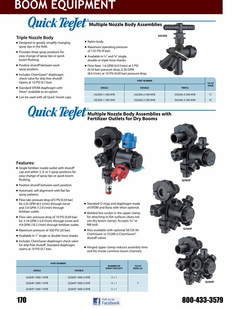
boom EquipmEnt
170 800-433-357950
QJ363F
QJ364F
QJ365F
QJ363F-1000-1-NYB QJ363F-1000-2-NYB 3 + 1
QJ364F-1000-1-NYB QJ364F-1000-2-NYB 4 + 1
QJ365F-1000-1-NYB QJ365F-1000-2-NYB 5 + 1
24230A-1-540-NYB 24230A-2-540-NYB 24230A-3-540-NYB
24230A-1-785-NYB 24230A-2-785-NYB 24230A-3-785-NYB
Triple Nozzle Bodyn Designed to greatly simplify changing
spray tips in the field.
n Provides three spray positions for easy change of spray tips or quick boom flushing.
n Positive shutoff between each spray position.
n Includes ChemSaver® diaphragm check valve for drip-free shutoff. Opens at 10 PSI (0.7 bar).
n Standard EPDM diaphragm with Viton® available as an option.
n Can be used with all Quick TeeJet caps.
n Nylon body.
n Maximum operating pressure of 125 PSI (9 bar).
n Available in 1/29 and 3/49 single, double or triple hose shanks.
n Flow Rate: 1.6 GPM (6.0 l/min) at 5 PSI (0.34 bar) pressure drop, 2.26 GPM (8.6 l/min) at 10 PSI (0.69 bar) pressure drop.
24230A
Features:n Single fertilizer nozzle outlet with shutoff
cap and either 3, 4, or 5 spray positions for easy change of spray tips or quick boom flushing.
n Positive shutoff between each position.
n Automatic self-alignment with flat fan spray patterns.
n Flow rate: pressure drop of 5 PSI (0.34 bar) for 2.25 GPM (8.5 l/min) through turret and 3.4 GPM (12.9 l/min) through fertilizer outlet.
n Flow rate: pressure drop of 10 PSI (0.69 bar) for 3.18 GPM (12.0 l/min) through turret and 4.8 GPM (18.2 l/min) through fertilizer outlet.
n Maximum pressure of 300 PSI (20 bar).
n Available in 19 single or double hose shanks.
n Includes ChemSaver diaphragm check valve for drip-free shutoff. Standard diaphragm opens at 10 PSI (0.7 bar). See page 60 for additional 21950 ChemSaver spring capacities.
n Standard O-rings and diaphragm made of EPDM and Buna with Viton optional.
n Molded hex socket in the upper clamp for attaching to flat surfaces (does not use dry boom clamp). Accepts 5/169 or M8 bolt.
n Also available with optional 56720 Air ChemSaver or 55280 e-ChemSaver® shutoff valves, see page 60 for additional information.
n Hinged upper clamp reduces assembly time and fits inside common boom channels.
Multiple Nozzle Body Assemblies
BOOM COMPONENTS
Multiple Nozzle Body Assemblies with Fertilizer Outlets for Dry Booms
pArt NuMBertO Fit hOse
siNgle DOuBle triple
1/29
3/49
pArt NuMBerNuMBer OF
sprAy OutletstO Fit
hOse i.D.siNgle DOuBle
19
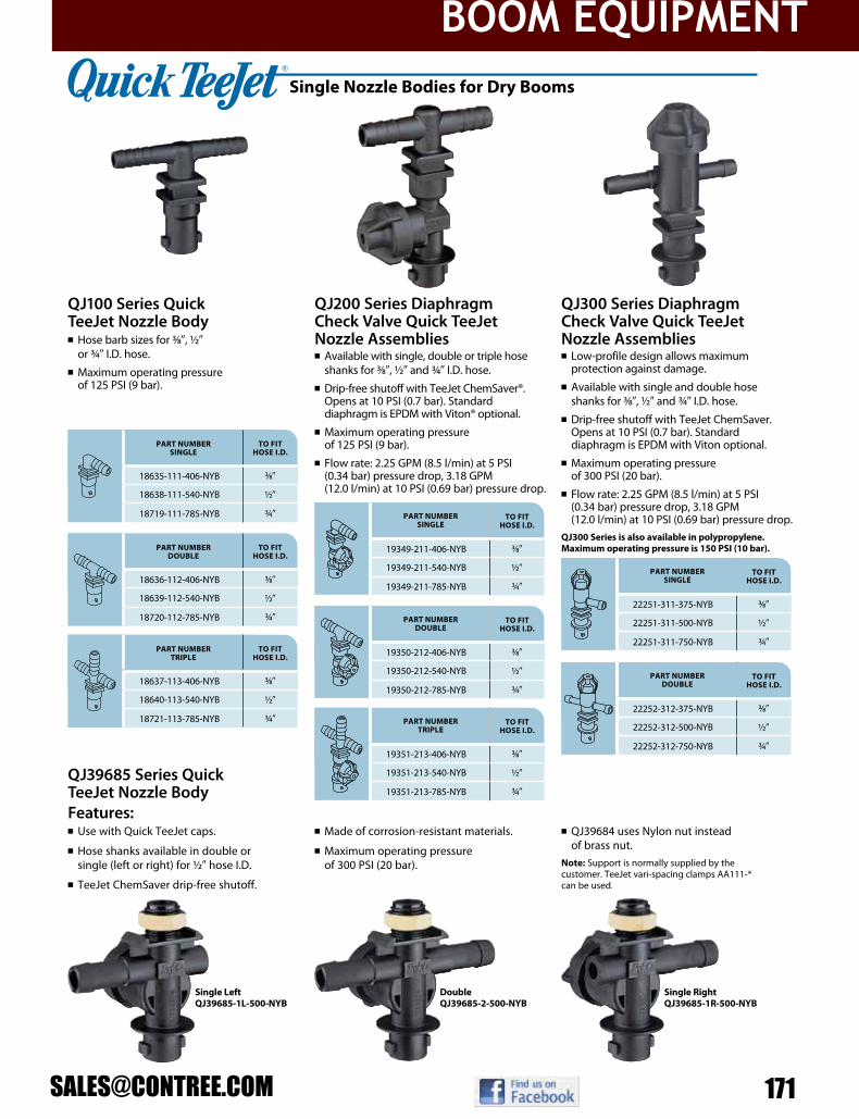
boom EquipmEnt
22252-312-375-NYB
22252-312-500-NYB
22252-312-750-NYB
22251-311-375-NYB
22251-311-500-NYB
22251-311-750-NYB
19351-213-406-NYB
19351-213-540-NYB
19351-213-785-NYB
19350-212-406-NYB
19350-212-540-NYB
19350-212-785-NYB
19349-211-406-NYB
19349-211-540-NYB
19349-211-785-NYB
18637-113-406-NYB
18640-113-540-NYB
18721-113-785-NYB
18636-112-406-NYB
18639-112-540-NYB
18720-112-785-NYB
18635-111-406-NYB
18638-111-540-NYB
18719-111-785-NYB
Double QJ39685-2-500-NYB
Single Right QJ39685-1R-500-NYB
Single Left QJ39685-1L-500-NYB
QJ39685 Series Quick TeeJet Nozzle BodyFeatures:n Use with Quick TeeJet caps.
n Hose shanks available in double or single (left or right) for 1/29 hose I.D.
n TeeJet ChemSaver drip-free shutoff.
n Made of corrosion-resistant materials.
n Maximum operating pressure of 300 PSI (20 bar).
n QJ39684 uses Nylon nut instead of brass nut.
Note: Support is normally supplied by the customer. TeeJet vari-spacing clamps AA111-* can be used. See page 64 for order information.
QJ300 Series Diaphragm Check Valve Quick TeeJet Nozzle Assemblies n Low-profile design allows maximum
protection against damage.n Available with single and double hose
shanks for 3/89, 1/29 and 3/49 I.D. hose.n Drip-free shutoff with TeeJet ChemSaver.
Opens at 10 PSI (0.7 bar). Standard diaphragm is EPDM with Viton optional.
n Maximum operating pressure of 300 PSI (20 bar).
n Flow rate: 2.25 GPM (8.5 l/min) at 5 PSI (0.34 bar) pressure drop, 3.18 GPM (12.0 l/min) at 10 PSI (0.69 bar) pressure drop.
QJ300 Series is also available in polypropylene. Maximum operating pressure is 150 PSI (10 bar).
QJ200 Series Diaphragm Check Valve Quick TeeJet Nozzle Assembliesn Available with single, double or triple hose
shanks for 3/89, 1/29 and 3/49 I.D. hose.n Drip-free shutoff with TeeJet ChemSaver®.
Opens at 10 PSI (0.7 bar). Standard diaphragm is EPDM with Viton® optional.
n Maximum operating pressure of 125 PSI (9 bar).
n Flow rate: 2.25 GPM (8.5 l/min) at 5 PSI (0.34 bar) pressure drop, 3.18 GPM (12.0 l/min) at 10 PSI (0.69 bar) pressure drop.
QJ100 Series Quick TeeJet Nozzle Bodyn Hose barb sizes for 3/89, 1/29
or 3/49 I.D. hose.n Maximum operating pressure
of 125 PSI (9 bar).
Note: See page 48 for vari-spacing clamps. See page 57 for Quick TeeJet caps.
Single Nozzle Bodies for Dry Booms
BOOM COMPONENTS
PaRt NuMBeR SINgLe
to fIt hoSe I.D.
3/89
1/29
3/49
PaRt NuMBeR DouBLe
to fIt hoSe I.D.
3/89
1/29
3/49
PaRt NuMBeR tRIPLe
to fIt hoSe I.D.
3/89
1/29
3/49
PaRt NuMBeR SINgLe
to fIt hoSe I.D.
3/89
1/29
3/49
PaRt NuMBeR DouBLe
to fIt hoSe I.D.
3/89
1/29
3/49
PaRt NuMBeR tRIPLe
to fIt hoSe I.D.
3/89
1/29
3/49
PaRt NuMBeR SINgLe
to fIt hoSe I.D.
3/89
1/29
3/49
PaRt NuMBeR DouBLe
to fIt hoSe I.D.
3/89
1/29
3/49

boom EquipmEnt
172 800-433-357947
Y33180-PP
Y9270-PP
Y33180-PP
Y9270-PP
Y33180-PP
Y9270-PP
Y33180-PP
Y9270-PP
6290SC-1 11118-1
6290SC-2 11118-2
6290SC-3 11118-3
6290SC-5 11118-5
6290SC-8 11118-8
6290SC-10 11118-10
approximate flow rate performance
model number
inlet liquid pressure
10 psi 15 psi 20 psi 25 psi 30 psi 35 psi 40 psi 50 psi
Inlet Flow Rate “A” (GPM)
9 11 12.7 14 16 17 18 20
13.5 17 19 21 23 25 27 30
Entrained Liquid “B” (GPM)
36 44 50.8 56 64 68 72 80
54 68 76 84 92 100 108 120
Circulation Rate “A”+“B” (GPM)
45 55 63.5 70 80 85 90 100
67.5 85 95 105 115 125 135 150
jet agitator number
orifice cap
number
orifice cap inlet
diameter
capacity (gpm) thru agitator line at various pressures for max. tank size in gallons of:10 psi 15 psi 20 psi 30 psi 40 psi 50 psi
.0559 .78 .96 1.1 1.4 1.6 1.8 50
.0869 1.9 2.3 2.7 3.3 3.8 4.3 110
.0969 2.4 2.9 3.3 4.1 4.7 5.3 140
.1449 4.4 5.4 6.2 7.6 8.8 9.9 250
.1569 5.1 6.3 7.2 8.8 10.2 11.4 300
.1779 5.7 7.0 8.0 9.7 11.4 12.7 350
model number pipe thread inlet connection orifice diameter length diameter
3/89 (M) 5/169 41/169 21/169
3/49 (M) 3/89 63/89 229/329
Circulation Rate “A” + “B”
Entrained Liquid “B”
DiffuserNozzle
Inlet Flow Rate “A”
Y33180-PP & Y9270-PP Features:n Allows small pumps to circulate large
volumes of liquid.
n Manufactured of glass-filled polypropylene for excellent corrosion and chemical resistance.
n Large flow opening minimizes plugging.
n Available in 3/89 or 3/49 (M) pipe thread inlet connection.
how to order:Specify nozzle number and inlet connection.
Example: Y33180-PP-3/8
how to order:Specify jet agitator number.
Examples: 6290SC-1 – Brass 6290SC-1-AL – Aluminum 6290SC-1-SS – Stainless Steel
Other sizes available.
note: Maximum tank sizes shown in table are approximate and are based on 40 PSI (3 bar) operation with pesticides, not fertilizers.
Installed at bottom of spray tank on end of agitator return line. Continuous solid stream jet flow creates turbulence and keeps wettable powders in suspension.
6290-SCMade in choice of brass, aluminum and all stainless steel. 1/49 NPT (F) inlet connection. Fits through 29 (51 mm) hole. Weight 6 oz. (0.17 kg). Siphon caps increase liquid flow by Venturi action to increase mixing potential.
jet agitators
eductor nozzles
TANK RINSING NOZZLES
56
CP21399-*-CE 21398H-*-CELR
CP23307-*-CE 23306H-*-CELR
CP58350-*-CE 58348H-*-CELR
1 2 3 4 5 6 7 8 10
QJ7421-1/2-NYB
QJ7421-3/4-NYB
QJ7421-1-NYB
QJ17560A
QJ22187
QJ7421
QJ17560A-20mm-NYB
QJ17560A-20mmx7-NYB
QJ17560A-25mm-NYB
QJ17560A-1/2-NYB
QJ17560A-1/2x7-NYB
QJ17560A-3/4-NYB
QJ17560A-1-NYB
QJ22187-1/2-NYB
QJ22187-3/4-NYB
QJ22187-1-NYB
Color Code
Note: When using TeeJet tip strainer, use CP26227 gasket in place of CP23308 gasket. See page 58 for 55240 Hardi to TeeJet adapter.
Single Nozzle Bodies for Wet Booms
Caps for Hardi® Nozzle Bodies
Ordering Information Black White Red Blue Green Yellow Brown Orange Violet
QUICK TEEJET CAPS
PART NUmBERFOR USE WITH FLAT SPRAY TIPS
150 PSI (10 bar) mAxImUm PRESSUREQUICK TEEJET CAP ONLY
QUICK TEEJET CAP & SEAT GASKET SET
TK FloodJet® FL FullJet® Tx ConeJet® TG Full Cone Hose Shank
BOOM COMPONENTS
n Can be mounted to 1/29, 3/49 or 19 pipe or equivalent size tubing.
n 1/29 and 3/49 sizes include a mounting hole in upper clamp subassembly for mounting to flat surfaces.
n Mounts to a 3/89 (9.5 mm) hole drilled in pipe or tubing.
n Maximum operating pressure of 300 PSI (20 bar).
QJ7421-NYB
n Can be mounted to 20 mm, 25 mm, 1/29, 3/49 or 19 pipe or equivalent size tubing.
n Features ChemSaver drip-free shutoff. Requires 10 PSI (0.7 bar) at the nozzle to open check valve.
n Standard diaphragm of EPDM with optional Viton available.
n Mounts to a 3/89 (9.5 mm) or 9/329 (7.0 mm) hole drilled in pipe or tubing.
QJ17560A-NYB
n Can be mounted to 1/29, 3/49 or 19 pipe or equivalent size tubing.
n 1/29 and 3/49 sizes include a mounting hole in clamp subassembly for mounting to flat surfaces.
n Allows side mounting to flat surface for protection of nozzle body.
n Features ChemSaver drip-free shutoff. Requires 10 PSI (0.7 bar) at the nozzle to open check valve.
n Standard diaphragm of EPDM with optional Viton available.
n Mounts to a 3/89 (9.5 mm) hole drilled in pipe or tubing.
n Maximum operating pressure of 300 PSI (20 bar).
n Flow rate: 2.5 GPM (9.5 l/min) at 5 PSI (0.34 bar) pressure drop, 3.54 GPM (13.4 l/min) at 10 PSI (0.69 bar) pressure drop.
QJ22187-NYB
PART NUmBER TO CLAmP ON DRILL HOLE SIzE UPPER CLAmP BOLT SIzE
1/29 Pipe .3759 (9.5 mm) 1/49
3/49 Pipe .3759 (9.5 mm) 1/49
19 Pipe .3759 (9.5 mm) N/A
PART NUmBER TO CLAmP ON DRILL HOLE SIzE UPPER CLAmP BOLT SIzE
20 mm Tubing .3759 (9.5 mm) 5/169 or M8
20 mm Tubing .2809 (7.0 mm) 5/169 or M8
25 mm Tubing .3759 (9.5 mm) 5/169 or M8
1/29 Pipe .3759 (9.5 mm) 5/169 or M8
1/29 Pipe .2809 (7.0 mm) 5/169 or M8
3/49 Pipe .3759 (9.5 mm) 5/169 or M8
19 Pipe .3759 (9.5 mm) 5/169 or M8
PART NUmBER TO CLAmP ON DRILL HOLE SIzE UPPER CLAmP BOLT SIzE
1/29 Pipe .3759 (9.5 mm) 1/49
3/49 Pipe .3759 (9.5 mm) 1/49
19 Pipe .3759 (9.5 mm) N/A
SJ3 StreamJet
DG TeeJet®
DG TwinJet®
Turbo TeeJet
AITTJ60 Turbo TwinJet
TTJ60 Turbo TwinJet
n All sizes include a mounting hole in upper clamp subassembly for mounting to flat surfaces.
n Maximum operating pressure of 300 PSI (20 bar).
n Flow rate: 2.25 GPM (8.5 l/min) at 5 PSI (0.34 bar) pressure drop, 3.18 GPM (12.0 l/min) at 10 PSI (0.69 bar) pressure drop.
TJ60 TwinJet®
TP Standard
AI TeeJet & AIUB TeeJet
AIxR TeeJetxR TeeJet®
Turbo TeeJet® Induction
OC TeeJet
(–0067 Thru –08) (–01 Thru –08) (–01 Thru –08)

boom EquipmEnt
QJ363CQJ363E
QJ365CQJ365E
QJ364CQJ364E
QJ364E-20mm-NYB 4
QJ364C-25mm-NYB 4
QJ364C-1/2-NYB 4
QJ364C-3/4-NYB 4
QJ364C-1-NYB 4
QJ365E-20mm-NYB 5
QJ365C-25mm-NYB 5
QJ365C-1/2-NYB 5
QJ365C-3/4-NYB 5
QJ365C-1-NYB 5
QJ363E-20mm-NYB 3
QJ363C-25mm-NYB 3
QJ363C-1/2-NYB 3
QJ363C-3/4-NYB 3
QJ363C-1-NYB 3
QJ360C Nozzle Body Series for Wet Boomsn Available with either 3, 4 or 5 spray
positions for easy change of spray tips or quick boom flushing.
n Positive shutoff between each position.
n Automatic spray alignment using flat fan spray tips.
n Maximum operating pressure of 300 PSI (20 bar).
n Available in 20 mm, 25 mm, 1/29, 3/49 or 19 pipe connections.
n Includes ChemSaver® diaphragm check valve for drip-free shutoff. Standard diaphragm opens at 10 PSI (0.7 bar). See page 60 for additional 21950 ChemSaver spring capacities.
n Standard EPDM diaphragm with Viton® available as an option.
n Also available with optional 56720 Air ChemSaver or 55280 e-ChemSaver® shutoff valves, see page 60 for additional information.
n Flow Rate: 2.25 GPM (8.5 l/min) at 5 PSI (0.34 bar) pressure drop, 3.18 GPM (12.0 l/min) with 10 PSI (0.69 bar) pressure drop.
n Mounts to a 3/89 (9.5 mm) hole drilled in pipe or tubing.
n Molded hex socket in upper clamp for attaching to flat surfaces. Accepts 5/169 or M8 bolt.
n Hinged upper clamp reduces assembly time and fits inside common boom channels.
Multiple Nozzle Bodies for Wet Booms
BOOM COMPONENTS
QJ360E Nozzle Body Series for Wet Boomsn Available to fit 20 mm O.D. tubing only.
n Flow Rate: 1.5 GPM (5.7 l/min) at 5 PSI (0.34 bar) pressure drop, 2.1 GPM (8.0 l/min) with 10 PSI (0.69 bar) pressure drop.
n Reduced internal cavity to increase ChemSaver shut-off speed.
n Notched inlet tube allows for more complete boom drainage and reduces sediment buildup.
part NuMBErNuMBEr
of spray outlEts
to ClaMp oN
20 mm Tubing
25 mm Tubing
1/29 Pipe
3/49 Pipe
19 Pipe
part NuMBErNuMBEr
of spray outlEts
to ClaMp oN
20 mm Tubing
25 mm Tubing
1/29 Pipe
3/49 Pipe
19 Pipe
part NuMBErNuMBEr
of spray outlEts
to ClaMp oN
20 mm Tubing
25 mm Tubing
1/29 Pipe
3/49 Pipe
19 Pipe
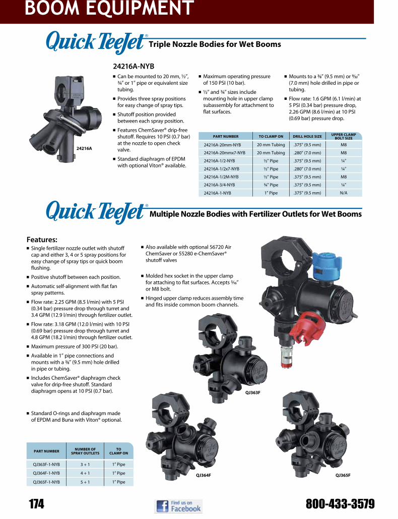
boom EquipmEnt
174 800-433-357954
QJ364F
QJ363F
QJ365F
QJ363F-1-NYB 3 + 1
QJ364F-1-NYB 4 + 1
QJ365F-1-NYB 5 + 1
24216A24216A-20mm-NYB
24216A-20mmx7-NYB
24216A-1/2-NYB
24216A-1/2x7-NYB
24216A-1/2M-NYB
24216A-3/4-NYB
24216A-1-NYB
24216A-NYB
Features:n Single fertilizer nozzle outlet with shutoff
cap and either 3, 4 or 5 spray positions for easy change of spray tips or quick boom flushing.
n Positive shutoff between each position.
n Automatic self-alignment with flat fan spray patterns.
n Flow rate: 2.25 GPM (8.5 l/min) with 5 PSI (0.34 bar) pressure drop through turret and 3.4 GPM (12.9 l/min) through fertilizer outlet.
n Flow rate: 3.18 GPM (12.0 l/min) with 10 PSI (0.69 bar) pressure drop through turret and 4.8 GPM (18.2 l/min) through fertilizer outlet.
n Maximum pressure of 300 PSI (20 bar).
n Available in 19 pipe connections and mounts with a 3/89 (9.5 mm) hole drilled in pipe or tubing.
n Includes ChemSaver® diaphragm check valve for drip-free shutoff. Standard diaphragm opens at 10 PSI (0.7 bar). See page 60 for additional 21950 ChemSaver spring capacities.
n Standard O-rings and diaphragm made of EPDM and Buna with Viton® optional.
Multiple Nozzle Bodies with Fertilizer Outlets for Wet Booms
BOOM COMPONENTS
pArt NuMBer NuMBer OF sprAy Outlets
tO clAMp ON
19 Pipe
19 Pipe
19 Pipe
n Also available with optional 56720 Air ChemSaver or 55280 e-ChemSaver® shutoff valves, see page 60 for additional information.
n Molded hex socket in the upper clamp for attaching to flat surfaces. Accepts 5/169 or M8 bolt.
n Hinged upper clamp reduces assembly time and fits inside common boom channels.
n Can be mounted to 20 mm, 1/29, 3/49 or 19 pipe or equivalent size tubing.
n Provides three spray positions for easy change of spray tips.
n Shutoff position provided between each spray position.
n Features ChemSaver® drip-free shutoff. Requires 10 PSI (0.7 bar) at the nozzle to open check valve.
n Standard diaphragm of EPDM with optional Viton® available.
n Maximum operating pressure of 150 PSI (10 bar).
n 1/29 and 3/49 sizes include mounting hole in upper clamp subassembly for attach ment to flat surfaces.
n Mounts to a 3/89 (9.5 mm) or 9/329 (7.0 mm) hole drilled in pipe or tubing.
n Flow rate: 1.6 GPM (6.1 l/min) at 5 PSI (0.34 bar) pressure drop, 2.26 GPM (8.6 l/min) at 10 PSI (0.69 bar) pressure drop.
pArt NuMBer tO clAMp ON Drill HOle size upper clAMp BOlt size
20 mm Tubing .3759 (9.5 mm) M8
20 mm Tubing .2809 (7.0 mm) M8
1/29 Pipe .3759 (9.5 mm) 1/49
1/29 Pipe .2809 (7.0 mm) 1/49
1/29 Pipe .3759 (9.5 mm) M8
3/49 Pipe .3759 (9.5 mm) 1/49
19 Pipe .3759 (9.5 mm) N/A
triple Nozzle Bodies for Wet Booms

boom EquipmEnt
1 2 3 4 5 6 7 8 9 10
CP25611- * -NY 25612- * -NYR
CP25611-9-PP†† 25612-9-PP††
CP25609- * -NY 25610- * -NYR
CP25597- * -NY 25598- * -NYR
CP25595- * -NY 25596- * -NYR
CP25599- * -NY 25600- * -NYR
CP25607- * -NY 25608- * -NYR
CP25607-9-PP†† 25608-9-PP††
CP25607- * -NY —
CP26277-1-NY† 26278-1-NYR†
— QJ4676-45-1/4-NYR†
— QJ4676-90-1/4-NYR†
—QJ4676-1/8-NYR†
QJ(B)4676-1/4-NYR†
— 19843-NYR†
TJ60 TwinJet® SJ3 StreamJet DG TwinJet®
TTDG TeeJet® AIXR TeeJet®TTJ60 Turbo TwinJet
AITXB ConeJet
OC TeeJet
AITTJ60 Turbo TwinJet
AITXA ConeJetTK FloodJet® FL FullJet® TX ConeJet®
TXB ConeJet®
Color Code
Ordering Information
The Quick TeeJet caps are designed with grooves that fit locating lugs on the nozzle body. Caps are made of Nylon and are available for use with all TeeJet® spray tips. Maximum operating pressure of 300 PSI (20 bar).
How to order: For cap and seat gasket set, specify set number and color code.
Example: 25612-3-NYRFor cap only, specify part number and color code.
Example: CP25597-4-NYFor seat gasket, specify part number.
Example: CP19438-EPR
* Specify color code (see chart). Violet (10) only available in CP25611 and CP25597 Nylon caps.†These Quick TeeJet caps available only in black.†† Polypropylene Quick TeeJet caps available only in gray and rated to 150 PSI (10 bar). Nylon caps not available in gray.
Quick TeeJet Cap and Seat Gasket Set
Quick TeeJet Cap
Seat Gasket
CP19438-VI (Viton Optional)
CP19438-EPR (EPDM Standard)
Caps
Black White Red Blue Green Yellow Brown Orange Gray†† Violet
QUICK TEEJET CAPS
PART NUMBERFOR USE WITH FLAT SPRAY TIPS
300 PSI (20 bar) MAXIMUM PRESSUREQUICK TEEJET CAP ONLY
QUICK TEEJET CAP & SEAT GASKET SET
TeeJet® Flat Spray Tips (Smaller Capacities)
TeeJet Flat Spray Tips (Larger Capacities)
TeeJet Flat Spray Tips (Smaller Capacities) Tips can be positioned in choice of two spray plane directions— parallel or perpendicular to wings of Quick TeeJet cap.
45° Quick TeeJet cap with 1/49 NPT female threaded outlet
90° Quick TeeJet cap with 1/49 NPT female threaded outlet
Permits use of standard 1/89 and 1/49 nozzles. Can be used for mounting pressure gauge at the nozzle. See Data Sheet 20055 for more information.
(B) = BSPT
Provides shutoff at nozzle for quick spacing change or change in spray swath.
XR –01 Thru –08
TP Standard –0067 Thru –08
TP Standard –10 Thru –20
XR –10 Thru –15
Turbo FloodJet® VisiFlo® Spray Tip
TK-VS FloodJet® VisiFlo Spray Tip
TK-VP FloodJet® VisiFlo Spray Tip
Locating Nib
Used with DC-Core Inserts and CP4916 Flow Regulators (Insert Core into Seal)
D-Disc CoreCore
SealCP18999-EPR
(EPDM standard)
CP18999-VI (Viton® optional)
AI TeeJet and AIUB TeeJet
Turbo TeeJet Induction®
TG Full Cone Hose Shank
Ceramic Disc-Core
D-Disc Core
BOOM COMPONENTS

boom EquipmEnt
176 800-433-357958
QJT8360-NYBQJP19011-NYB
QJ90-2-NYR
QJ90-1-NYR
22674-1/4-NYB
QJ8355-1/8-NYB
QJ8355-1/4-NYB
QJ8360-NYB
(B)QJ1/4T-NYB
QJT-NYB
QJ(B)1/4TT-NYB
QJ(B)8360-NYB
QJT8360-NYB
QJP19011-NYB
QJT8360-NYB, QJP19011-NYB, QJ8360-NYBn Retrofits to a Quick TeeJet
system.n Features ChemSaver®
no-drip shutoff. Requires 10 PSI (0.7 bar) at the nozzle to open check valve.
n Standard diaphragm of EPDM with optional Viton® available upon request.
n Maximum operating pressure of 300 PSI (20 bar).
n Flow rate: 2.25 GPM (8.5 l/min) at 5 PSI (0.34 bar) pressure drop, 3.18 GPM (12.0 l/min) at 10 PSI (0.69 bar) pressure drop.
22674-1/4-NYBn Allows use of Quick
TeeJet system with 1/49 NPT female connections.
QJ8355-NYBn Allows use of Quick TeeJet
system with 1/89 and 1/49 NPT female connections.
n Side mounting provides protection of the nozzle body.
n Features ChemSaver no-drip shutoff. Requires 10 PSI (0.7 bar) at the nozzle to open check valve.
n Standard diaphragm of EPDM with optional Viton available upon request.
n Maximum operating pressure of 300 PSI (20 bar).
n Flow rate: 2.25 GPM (8.5 l/min) at 5 PSI (0.34 bar) pressure drop, 3.18 GPM (12.0 l/min) at 10 PSI (0.69 bar) pressure drop.
QJ90-1-NYRn Fits standard Quick
TeeJet bodies.n Nylon body construction
for strength and durability, with EPDM gasket (Viton® optional).
n Outlet can be fitted with Quick TeeJet caps and TeeJet spray tips.
n One piece, 90° elbow is ideal for installation of TK-VS FloodJet® and TF-VS or TF-VP Turbo FloodJet nozzles on single or multiple outlet nozzle bodies. Proper orientation of spray tip enhances spray distribution quality.
n Adapter outlet accepts standard tip strainers.
n Maximum operating pressure of 300 PSI (20 bar).
55240-CELRn Converts Hardi® snap-fit
nozzle body connection to Quick TeeJet connection for easy installation of TeeJet tips. Especially useful for AIC, XRC and SJ7 tips.
n Acetal construction with EPDM gasket for durability and chemical resistance.
n Accepts standard tip strainers.n Maximum operating pressure of 150 PSI
(10 bar).
Adapters and Accessories
BOOM COMPONENTS
PArT NumBer To fiT
1/89 (F)
1/49 (F)
PArT NumBer To fiT
1/49 (M) thread
PArT NumBer To fiT
Quick TeeJet
PArT NumBer To fiT
Quick TeeJet
QJ1/4TT-NYBn Allows use of Quick TeeJet
system with 1/49 NPT and BSPT female connections.
n Maximum operating pressure of 300 PSI (20 bar).
50854-NYBn For use with Quick TeeJet
nozzle bodies to extend body length by 1 inch (25 mm).
n Used to eliminate interference of spray pattern with sprayer boom structure or shields, particularly with twin pattern or fertilizer spray tips.
n Nylon body construction with EPDM gasket.n Maximum operating pressure of 300 PSI
(20 bar).
(B)=BSPT
PArT NumBer To fiT
1/49 (M) thread
(B)=BSPT
PArT NumBer To fiT
1/49 (M) thread
11/169–16 TeeJet thread
3/89 BSPP thread
QJ1/4T-NYB & QJT-NYBn QJ1/4T-NYB allows use of Quick
TeeJet system with 1/49 NPT and BSPT male connections.
n QJT-NYB permits use of Quick TeeJet system with standard 11/169–16 TeeJet thread.
n Maximum operating pressure of 300 PSI (20 bar).
(B)=BSPT
PArT NumBer To fiT
1/49 (F) thread
1/169–16 TeeJet thread
QJ90-2-NYRn Fits standard Quick TeeJet
bodies. n Made of Nylon with
CP19438-EPR gasket (included).
n Use with Quick TeeJet cap and gasket for automatic alignment when using flat fan spray tips.
n 90° included angle between outlets. When used with standard flat fan tips produces a twin type spray pattern for improved coverage and canopy penetration.

boom EquipmEnt
A21353-6-15-NYB
21353-6-24-NYB
B21354-15-NYB
21354-24-NYB
QJ8600-2-1/4-NYB QJ8600-1/4-NYB
(B)5540-1/4TT 280°(B)5000-1/4T 280°
(B)6240-1/4TT 280° (B)7450-2T 280°4202-2-1/4T 280°
5932-2-1/4T 280°
(B)7620-T 360°
8600-1/4T-NYB 280° 8600-2-1/4T-NYB 280°
Note: QJ1/4T-NYB can be attached to hose drops for use with Quick TeeJet caps. See page 58 for ordering information.
Hose drops connect to standard and Quick TeeJet nozzle bodies and can also be used with swivels. Available in 159 (380 mm) and 249 (610 mm) lengths. Maximum operating pressure of 125 PSI (9 bar).
Swivel Nozzle BodiesTeeJet swivel nozzle bodies are primarily for use with tips employed in row crop spraying. A locknut holds swivel bodies firmly in position at selected spray projection angle so they are not affected by jarring and vibration. For use at pressures up to 125 PSI (9 bar).
How to order: Examples: 5000-1/4T Brass NPT
B5000-1/4T Brass BSPT
Note: Swivels do not include tips, strainers or caps.
Type 5932 Double Swivel Nozzle 1/49 NPT female bottom outlet
Type 5540Single Swivel Nozzle
Type 7620 CompactSingle Swivel Nozzle
Type 8600-2 NylonDouble Swivel Nozzle
Type 8600 NylonSingle Swivel Nozzle
Type 7450 CompactDouble Swivel Nozzle
Type 6240Double Swivel Nozzle
Type 5000Single Swivel Nozzle
Type 4202Double Swivel Nozzle
QJ8600-1/4-NYBSingle Swivel Nozzle
QJ8600-2-1/4-NYBDouble Swivel Nozzle
Quick TeeJet® Swivel Nozzle BodiesQJ8600 swivel Quick TeeJet nozzle body assemblies provide the same spray tip adjustability of a standard TeeJet threaded swivel plus the quick change and self-aligning features of the Quick TeeJet System.
BA
QJ1/4T-NYB
Swivel Nozzle Bodies
BOOM COMPONENTS
Hose Drops
pArT NumBer pipe THreAD mATeriAl
1/49 NPT (F) Nylon
pArT NumBer pipe THreAD mATeriAl
1/49 NPT (F) Nylon
pArT NumBer
iNleT CoNNeCTioN mATeriAl Swivel
ArC rANge
1/49 NPT (F) Brass
pArT NumBer
iNleT CoNNeCTioN mATeriAl Swivel
ArC rANge
1/49 NPT (M) Brass
pArT NumBer
iNleT CoNNeCTioN mATeriAl Swivel
ArC rANge
1/49 NPT (F) Brass
pArT NumBer
iNleT CoNNeCTioN mATeriAl Swivel
ArC rANge
1/49 NPT (M) Brass
pArT NumBer
iNleT CoNNeCTioN mATeriAl Swivel
ArC rANge
1/49 NPT (F) Brass
pArT NumBer
iNleT CoNNeCTioN mATeriAl Swivel
ArC rANge
1/49 NPT (F) Brass
pArT NumBer
iNleT CoNNeCTioN mATeriAl Swivel
ArC rANge
1/49 NPT (F) Nylon
pArT NumBer
iNleT CoNNeCTioN mATeriAl Swivel
ArC rANge
1/49 NPT (F) Nylon
pArT NumBer
iNleT CoNNeCTioN mATeriAl Swivel
ArC rANge
1/49 NPT (F) Brass
iTem HoSe Drop NumBer leNgTH iNleT CoNNeCTioN
ouTleT CoNNeCTioN mATeriAl
159 (380 mm) Quick TeeJet Type
1/49 NPT (M)
Nylon with Quick TeeJet cap and EPDM gasket249 (610 mm)
159 (380 mm) 11/169–16 TeeJet Thread
Nylon249 (610 mm)

boom EquipmEnt
178 800-433-357964
=
AA111SQ
AA111
CP1325 CP18032A-NYB
CP(B)1335 1/8T
CP(B)1321 1/4T
CP(B)12094-NYB 1/4T-NYB
CP(B)1321-I 1/4T-I
CP(B)1321-SS 1/4T-SS
CP(B)1323 3/8T
CP(B)1339 1/2T
CP3817 3/4T
CP3817-SS 3/4T
CP(B)1336 1/8TT
CP(B)1322 1/4TT
CP(B)8028-NYB 1/4TT-NYB
CP(B)1322-I 1/4TT-I
CP(B)1322-SS 1/4TT-SS
CP(B)1324 3/8TT
CP(B)1340 1/2TT
CP(B)3818 3/4TT
CP(B)3818-SS 3/4TT
(B)22669-1/4-PPB
CP1325
CP8027-NYB
CP8027-1-NYB
CP1325-AL
CP1325-SS
CP18032A-NYB
CP3819
CP3819-SS
CP20230
+
+
+
+
AA111SQ-1
AA111SQ-1-1/4
AA111SQ-1-1/2
AA111-1/2
AA111-3/4
AA111-1
AA111-1-1/4
45° Nozzle BodyIdeal for use with FullJet®, FloodJet® and Turbo FloodJet® nozzles. Can be used with QJ4676 Quick TeeJet® cap or standard 4676 outlet adapter. Made of polypropylene.
TeeJet Nozzle CapsSecure interchangeable TeeJet tips to the various nozzle bodies. 18032A-NYB winged TeeJet cap allows quick change of spray tips with no tool required.
11750 TeeJet Check ValveFor larger capacity TeeJet nozzles where strainers are not required. Ball check opens at 5 PSI (0.34 bar), 10 PSI (0.7 bar) spring also available. Recommended for flow rates from .40 to 1.5 GPM (1.5–5.7 l/min). Made in choice of stainless steel, brass, aluminum or poly propy lene with stainless steel ball and spring.
Standard Parts
CP1325 TeeJet Cap
Spray Tip
5053 Strainer
Type T or TT nozzle body
TeeJet Spray Nozzle
Clamp AssembliesConsist of upper and lower clamps and bolt for use with hose shank nozzle bodies.
How to order:Specify part number.
Example: (B)22669-1/4-PPB
TeeJet Nozzle BodiesType-TTMale Inlet NPT or BSPT Connection
(B) = BSPT
(B) = BSPT
(B) = BSPTType-TFemale Inlet NPT or BSPT Connection
Nozzle Parts
BOOM COMPONENTS
Optional Tip GasketCP5871-BU
TeeJeT CAP NumBer DeSCriPTioN
Brass
Nylon
Nylon (Extra-long size)
Aluminum
Stainless Steel
Winged Cap, Nylon
Brass, use with 3/4T & 3/4TT body
Stainless Steel, use with 3/4T & 3/4TT body
Brass, use with ceramic disc-cores
TeeJeT BoDY NumBer iNleT ouTleT
1/49 (M) 11/169–16 (M)
TeeJeT BoDY NumBer
for TeeJeT Nozzle TYPe femAle Size mATeriAl
1/89 Brass
1/49 Brass
1/49 Nylon
1/49 Steel
1/49 Stainless Steel
3/89 Brass
1/29 Brass
3/49 Brass
3/49 Stainless Steel
TeeJeT BoDY NumBer
for TeeJeT Nozzle TYPe mAle Size mATeriAl
1/89 Brass
1/49 Brass
1/49 Nylon
1/49 Steel
1/49 Stainless Steel
3/89 Brass
1/29 Brass
3/49 Brass
3/49 Stainless Steel
PArT NumBer To ClAmP oN
19 Square Tubing
11/49 Square Tubing
11/29 Square Tubing
PArT NumBer To ClAmP oN
1/29 Pipe (13/169 & 7/89 O.D. Tubings)
3/49 Pipe (19 & 11/169 O.D. Tubings)
19 Pipe (11/89, 11/49 & 13/89 O.D. Tubings)
11/49 Pipe (19/169 & 111/169 O.D. Tubings)

boom EquipmEnt
4510223174
19845-PP60515053 8079
4514-*-10 50
4514-*-20 25
4514-*-32 16
4193A- * - *
4193A-SS- * - *
4193A-PP- * - *
4193A-PP-*-SS-*
5053*
8079-PP*
6051-SS*
19845-PP*
1624255080
100200
55215-50-* 50
55215-100-* 100
AA(B)122-1/2-PP-*
AA(B)122-3/4-PP-*
AA(B)122ML-1/2-PP-*
AA(B)122ML-3/4-PP-*
(B)37270-122-1/2-PP-*
(B)37270-122-3/4-PP-*
16 CP23174-1-SS
30 CP23174-2-SS
50 CP45102-3-SSPP
80 CP45102-4-SSPP
100 CP45102-5-SSPP
200 CP23174-7-SS
TeeJet Slotted StrainersOne-piece strainers for use with liquids containing suspended solids.
TeeJet StrainersStrainers protect spray tip orifices from clogging and damage. Stainless steel screens are available in 24, 50, 80, 100 and 200 mesh. 19845 tip strainers are available in 25 and 50 mesh only.
*Above numbers for brass. For Nylon add “NY”. For aluminum add “AL”.
*Specify mesh size when ordering.
55215 Self-Retaining Tip StrainerFeatures:n For Use with Quick TeeJet® caps.n Allows tip strainer to be easily
removed from nozzle body for cleaning.
n 50 or 100 mesh color-coded strainer with optional EPDM or Viton® gasket.
How to order: Example: 55215-50-EPR, EPDM gasket
55215-50-VI, Viton gasket
4193A TeeJet Strainer and Check ValveMinimizes nozzle dripping; fits all TeeJet nozzles. Ball check opens at 5 PSI (0.34 bar). Recommended for flow rates up to 0.8 GPM (3 l/min). 24, 50, 100 and 200 mesh screens. Not for use with AI or DG tips.Note: Use of these ball check valves results in a pressure drop of 5 PSI (0.34 bar) to 10 PSI (0.7 bar) depending on spring rating.
*When ordering, specify spring rating and screen mesh size.
37270-122-PPThe screen may be periodically flushed by opening a valve (valve not included) in flush-out line.
37270-122-PPFlush-Out Strainer
AA122-MLCompact
Liquid Strainer
AA122-PPCompact
Liquid Strainer
* = Mesh Size (B) = BSPTReplacement Head Gasket: CP23173-EPR(-VI)
The AA122 line strainer features a compact size that is well suited for small agricultural and turf sprayers. The AA122 is constructed of poly propylene head and bowl with stainless steel screen for excellent chemical resistance and is avail able with 1/29 or 3/49 (F) NPT pipe con nections. The maxi mum pressure rating is 150 PSI (10 bar).
Line Strainers
Tip Strainers
STRAINERS
TEEJET STRAINER NUMBER
AvAILABLE MATERIAL EqUIvALENT To MESH SIzE
CoLoR CodE (NyLoN
vERSIoNS oNLy)
Brass or Nylon
Brass, Aluminum or Nylon
Brass, Aluminum or Nylon
TEEJET STRAINER NUMBER
STRAINER Body ANd CAP MATERIAL MESH SCREEN MATERIAL
Brass Stainless Steel
Polypropylene Stainless Steel
Stainless Steel Stainless Steel
Polypropylene Polypropylene
CHECk vALvE NUMBER
Body ANd CAP SCREw MATERIAL
MESH SCREEN MATERIAL BALL MATERIAL
Brass Stainless Steel Stainless Steel
Stainless Steel Stainless Steel Stainless Steel
Polypropylene Stainless Steel Viton
Polypropylene Stainless Steel Stainless Steel
STRAINER NUMBER
PIPE CoNN.
APPRoxIMATE fLow RATE wITH
5 PSI (0.34 bar) PRESSURE dRoP
IN GPM (l/min)
SCREENPRESSURE
RATING PSI (bar)MESH
SIzEPART
NUMBER
1/29 12 (45)
3/49 16 (60)
1/29 12 (45)
3/49 16 (60)
1/29 12 (45)
3/49 16 (60)
MESH SIzE
*Identify gasket material.
STRAINER NUMBER MESH
150 PSI (10 bar)
We carry the full line up of Tee-Jet products!
If you don’t see the part listed that you need just contact us and we can order it for you.
Contact one of our sales team-
1-800-433-3579 or [email protected]

boom EquipmEnt
180 800-433-3579128
Folia
rCo
ntac
t
Folia
rSy
stem
ic
Soil
Appl
ied
Draf
tCo
ntro
l
Spray Tip Selection GuideThe following chart has been designed to simplify selection of the correct spray tip type for the agrochemical to be applied. It is based on having good conditions for spraying and should be used in conjunction with the agrochemical manufacturer’s label. Increased carrier rates may allow for coarser sprays to reduce risk of drift. Always follow the agrochemical label exactly.
Sect
ion
Code Spray Tip Orifice MaterialPressure Range
nominal Spray Angle Pattern XF VF F M C VC XC UC
Broa
dcas
t
ULD Ultra Lo-Drift™ Polyacetal 15 to 115 120 Tapered Fan Good† Excellent Excellent Excellent
ATW Air-Injected Twin Fan Ceramic 40 to 100 110 Twin Tapered Fan Good† Excellent – Excellent
AVI Air-Injected Anti-Drift Ceramic 30 to 100 80,110 Tapered Fan – Excellent Excellent Excellent
GAT GuardianAIR™ Twin Polyacetal 30 to 115 110 Twin Tapered Fan Excellent Excellent – Very Good
GA GuardianAIR™ Polyacetal 15 to 115 110 Tapered Fan Excellent Excellent Very Good Very Good
GRD Guardian™ Polyacetal 15 to 115 120 Tapered Fan Excellent Excellent Very Good Good
LD Lo-Drift™ Polyacetal 15 to 70 80,110 Tapered Fan Very Good Excellent Very Good Good
ADI Drift Reduction Ceramic 30 to 70 110 Tapered Fan Excellent Excellent Very Good Good
VP Variable Pressure Fan Polyacetal 15 to 70 80,110 Tapered Fan Very Good Good Good –
AXI Wide Range Fan Ceramic 20 to 70 80,110 Tapered Fan Very Good Good Good –
TR Total Range™ Stainless Steel 15 to 70 80,110 Tapered Fan Very Good Good Good –
F FanTip™ Standard Fan Polyacetal 30 to 60 80,110 Tapered Fan Good Good Good –
ACID F FanTip™ Standard Fan PVDF 110 Tapered Fan Good Good – –
ACID LD Lo-Drift™ PVDF 110 Tapered Fan Very Good Excellent Very Good Good
Wid
e
HF Hi-Flow™ Polyacetal 20 to 80 140 Wide-angle Tapered Fan – Excellent* Excellent Excellent
DT DeflecTip™ Polyacetal 15 to 60 80 to 145 Wide-angle Flood – Good Very Good Good
APM Wide-Angle Flood Ceramic 10 to 60 80 to 160 Wide-angle Flood – Good Very Good Good
Stre
am
ESI Six Stream Ceramic 15 to 60 0 6-stream – – Excellent Excellent SCM Straight Stream PVDF 15 to 150 0 Stream – – Very Good Very Good SDC Flow-Regulating Disc Polyacetal 10 to 150 0 Stream – – Very Good Very Good SAMT Flow-Regulating Disc Ceramic 10 to 725 0 Stream – – Very Good Very Good S
Band
ing
& Di
rect
ed
DC/CR SwirlTip™ Disc/Core Polyacetal 10 to 150 45 to 110 Hollow Cone Very Good Good – –
DCC/CRC Disc and Core Ceramic 10 to 300 13 to 93 Hollow Cone Very Good Good – –
HCX HollowTip™ Hollow Cone Polyacetal 40 to 150 80 Hollow Cone Very Good Good – –
ATR Hollow Cone Ceramic 40 to 350 80 Hollow Cone Very Good Good – –
HCA Hollow Cone Ceramic 40 to 350 80 Hollow Cone Very Good Good – –
TVI Hollow Cone Ceramic 70 to 360 80 Hollow Cone Good* Excellent – Excellent
AVI FanTip™ Ceramic 40 to 350 80 Tapered Fan Good Excellent – Excellent
AXI FanTip™ Ceramic 40 to 350 80 Tapered Fan Very Good Good – –
FCX Full Cone Polyacetal 15 to 150 80 Full Cone Good Very Good – –
DCC/CRC Disc and Core Ceramic 10 to 300 14 to 70 Full Cone Good Very Good – –
E Fan Tip™ Even Flat Polyacetal 30 to 60 80 Even Fan Very Good Very Good Very Good –
OC Off-Center Flat Brass 30 to 60 80 Off-center Tapered Fan Good Good Good –
OCI Off-Center Ceramic Ceramic 30 to 60 80 Off-center Tapered Fan Good Good Good –
AVI-OC Air-Injected Off-Center Ceramic 40 to 100 80 Off-center Tapered Fan Good Excellent Excellent Excellent
Spec
ial XT Boom X Tender™ Polyacetal or
Stainless Steel30 to 60 105
Ultra-wide Boomless Fan
– Very Good Very Good Very Good
MISTING F, HAF, PF, AFD, AF Polyacetal 40 to 150 65 to 110 Fan or Hollow Cone
TC TwinCap™ Polyacetal or PVDF
--- --- Double Tip Holder
Color Code ClassificationXF Extremely FineVF Very FineF FineM MediumC Coarse
VC Very CoarseXC Extremely CoarseUC Ultra Coarse
S These nozzles produce streams to minimize atomization.* at high volume † at high pressure
Manufacturer's recommended droplet size
Hypro Spray Tip Selection Guide
Folia
rCo
ntac
t
Folia
rSy
stem
ic
Soil
Appl
ied
Draf
tCo
ntro
l
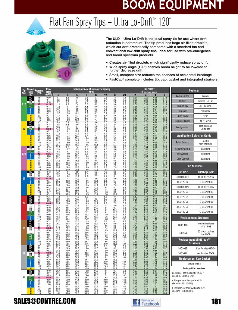
boom EquipmEnt
The ULD – Ultra Lo-Drift is the ideal spray tip for use where drift reduction is paramount. The tip produces large air-filled droplets,which cut drift dramatically compared with a standard fan and conventional low-drift spray tips. Ideal for use with pre-emergenceand broad spectrum products.
Application Selection Guide
Foliar Contact Good athigh pressure
Foliar Systemic Excellent
Soil Applied Excellent
Drift Control Excellent
TipSize
DropletSize120º
Pressure(PSI)
Flow Rate
(GPM)
Gallons per Acre 20 inch nozzle spacing MPH
GAL/1000 Ft 2
20 inch nozzle spacing
4 5 6 8 10 12 15 20 2 3 4 5UC 15 0.09 6.7 5.3 4.5 3.3 2.7 2.2 1.8 1.3 0.31 0.20 0.15 0.12UC 20 0.11 8.2 6.5 5.4 4.1 3.3 2.7 2.2 1.6 0.38 0.25 0.19 0.15XC 30 0.13 9.7 7.7 6.4 4.8 3.9 3.2 2.6 1.9 0.44 0.30 0.22 0.18
015 VC 40 0.15 11.1 8.9 7.4 5.6 4.5 3.7 3.0 2.2 0.51 0.34 0.26 0.20VC 50 0.17 12.6 10.1 8.4 6.3 5.0 4.2 3.4 2.5 0.58 0.39 0.29 0.23C 60 0.18 13.4 10.7 8.9 6.7 5.3 4.5 3.6 2.7 0.61 0.41 0.31 0.25C 70 0.20 14.9 11.9 9.9 7.4 5.9 5.0 4.0 3.0 0.68 0.45 0.34 0.27C 80 0.21 15.6 12.5 10.4 7.8 6.2 5.2 4.2 3.1 0.72 0.48 0.36 0.29M 90 0.23 17.1 13.7 11.4 8.5 6.8 5.7 4.6 3.4 0.78 0.52 0.39 0.31M 100 0.24 17.8 14.3 11.9 8.9 7.1 5.9 4.8 3.6 0.82 0.55 0.41 0.33M 115 0.25 18.6 14.9 12.4 9.3 7.4 6.2 5.0 3.7 0.85 0.57 0.43 0.34UC 15 0.12 8.9 7.1 5.9 4.5 3.6 3.0 2.4 1.8 0.41 0.27 0.20 0.16UC 20 0.14 10.4 8.3 6.9 5.2 4.2 3.5 2.8 2.1 0.48 0.32 0.24 0.19XC 30 0.17 12.6 10.1 8.4 6.3 5.0 4.2 3.4 2.5 0.58 0.39 0.29 0.23
02 VC 40 0.20 14.9 11.9 9.9 7.4 5.9 5.0 4.0 3.0 0.68 0.45 0.34 0.27C 50 0.22 16.3 13.1 10.9 8.2 6.5 5.4 4.4 3.3 0.75 0.50 0.38 0.30C 60 0.24 17.8 14.3 11.9 8.9 7.1 5.9 4.8 3.6 0.82 0.55 0.41 0.33M 70 0.26 19.3 15.4 12.9 9.7 7.7 6.4 5.1 3.9 0.89 0.59 0.44 0.35M 80 0.28 20.8 16.6 13.9 10.4 8.3 6.9 5.5 4.2 0.95 0.64 0.48 0.38M 90 0.30 22.3 17.8 14.9 11.1 8.9 7.4 5.9 4.5 1.02 0.68 0.51 0.41M 100 0.32 23.8 19.0 15.8 11.9 9.5 7.9 6.3 4.8 1.09 0.73 0.55 0.44M 115 0.34 25.2 20.2 16.8 12.6 10.1 8.4 6.7 5.0 1.16 0.77 0.58 0.46UC 15 0.15 11.1 8.9 7.4 5.6 4.5 3.7 3.0 2.2 0.51 0.34 0.26 0.20XC 20 0.18 13.4 10.7 8.9 6.7 5.3 4.5 3.6 2.7 0.61 0.41 0.31 0.25VC 30 0.22 16.3 13.1 10.9 8.2 6.5 5.4 4.4 3.3 0.75 0.50 0.38 0.30
025 C 40 0.25 18.6 14.9 12.4 9.3 7.4 6.2 5.0 3.7 0.85 0.57 0.43 0.34C 50 0.28 20.8 16.6 13.9 10.4 8.3 6.9 5.5 4.2 0.95 0.64 0.48 0.38C 60 0.31 23.0 18.4 15.3 11.5 9.2 7.7 6.1 4.6 1.06 0.70 0.53 0.42M 70 0.33 24.5 19.6 16.3 12.3 9.8 8.2 6.5 4.9 1.13 0.75 0.56 0.45M 80 0.35 26.0 20.8 17.3 13.0 10.4 8.7 6.9 5.2 1.19 0.80 0.60 0.48M 90 0.38 28.2 22.6 18.8 14.1 11.3 9.4 7.5 5.6 1.30 0.86 0.65 0.52M 100 0.40 29.7 23.8 19.8 14.9 11.9 9.9 7.9 5.9 1.36 0.91 0.68 0.55M 115 0.42 31.2 24.9 20.8 15.6 12.5 10.4 8.3 6.2 1.43 0.95 0.72 0.57UC 15 0.18 13.4 10.7 8.9 6.7 5.3 4.5 3.6 2.7 0.61 0.41 0.31 0.25XC 20 0.21 15.6 12.5 10.4 7.8 6.2 5.2 4.2 3.1 0.72 0.48 0.36 0.29XC 30 0.26 19.3 15.4 12.9 9.7 7.7 6.4 5.1 3.9 0.89 0.59 0.44 0.35
03 C 40 0.30 22.3 17.8 14.9 11.1 8.9 7.4 5.9 4.5 1.02 0.68 0.51 0.41C 50 0.34 25.2 20.2 16.8 12.6 10.1 8.4 6.7 5.0 1.16 0.77 0.58 0.46C 60 0.37 27.5 22.0 18.3 13.7 11.0 9.2 7.3 5.5 1.26 0.84 0.63 0.50M 70 0.40 29.7 23.8 19.8 14.9 11.9 9.9 7.9 5.9 1.36 0.91 0.68 0.55M 80 0.42 31.2 24.9 20.8 15.6 12.5 10.4 8.3 6.2 1.43 0.95 0.72 0.57M 90 0.45 33.4 26.7 22.3 16.7 13.4 11.1 8.9 6.7 1.53 1.02 0.77 0.61M 100 0.47 34.9 27.9 23.3 17.4 14.0 11.6 9.3 7.0 1.60 1.07 0.80 0.64M 115 0.51 37.9 30.3 25.2 18.9 15.1 12.6 10.1 7.6 1.74 1.16 0.87 0.70UC 15 0.24 17.8 14.3 11.9 8.9 7.1 5.9 4.8 3.6 0.82 0.55 0.41 0.33UC 20 0.28 20.8 16.6 13.9 10.4 8.3 6.9 5.5 4.2 0.95 0.64 0.48 0.38UC 30 0.35 26.0 20.8 17.3 13.0 10.4 8.7 6.9 5.2 1.19 0.80 0.60 0.48
04 UC 40 0.40 29.7 23.8 19.8 14.9 11.9 9.9 7.9 5.9 1.36 0.91 0.68 0.55XC 50 0.45 33.4 26.7 22.3 16.7 13.4 11.1 8.9 6.7 1.53 1.02 0.77 0.61XC 60 0.49 36.4 29.1 24.3 18.2 14.6 12.1 9.7 7.3 1.67 1.11 0.84 0.67XC 70 0.53 39.4 31.5 26.2 19.7 15.7 13.1 10.5 7.9 1.81 1.20 0.90 0.72VC 80 0.57 42.3 33.9 28.2 21.2 16.9 14.1 11.3 8.5 1.94 1.30 0.97 0.78VC 90 0.60 44.6 35.6 29.7 22.3 17.8 14.9 11.9 8.9 2.05 1.36 1.02 0.82C 100 0.63 46.8 37.4 31.2 23.4 18.7 15.6 12.5 9.4 2.15 1.43 1.07 0.86C 115 0.68 50.5 40.4 33.7 25.2 20.2 16.8 13.5 10.1 2.32 1.55 1.16 0.93
UC 15 0.31 23.0 18.4 15.3 11.5 9.2 7.7 6.1 4.6 1.06 0.70 0.53 0.42UC 20 0.35 26.0 20.8 17.3 13.0 10.4 8.7 6.9 5.2 1.19 0.80 0.60 0.48UC 30 0.43 31.9 25.5 21.3 16.0 12.8 10.6 8.5 6.4 1.47 0.98 0.73 0.59
05 XC 40 0.50 37.1 29.7 24.8 18.6 14.9 12.4 9.9 7.4 1.71 1.14 0.85 0.68XC 50 0.56 41.6 33.3 27.7 20.8 16.6 13.9 11.1 8.3 1.91 1.27 0.95 0.76XC 60 0.61 45.3 36.2 30.2 22.6 18.1 15.1 12.1 9.1 2.08 1.39 1.04 0.83VC 70 0.66 49.0 39.2 32.7 24.5 19.6 16.3 13.1 9.8 2.25 1.50 1.13 0.90VC 80 0.71 52.7 42.2 35.1 26.4 21.1 17.6 14.1 10.5 2.42 1.61 1.21 0.97VC 90 0.75 55.7 44.6 37.1 27.8 22.3 18.6 14.9 11.1 2.56 1.71 1.28 1.02C 100 0.79 58.7 46.9 39.1 29.3 23.5 19.6 15.6 11.7 2.69 1.80 1.35 1.08C 115 0.85 63.1 50.5 42.1 31.6 25.2 21.0 16.8 12.6 2.90 1.93 1.45 1.16
UC 15 0.37 27.5 22.0 18.3 13.7 11.0 9.2 7.3 5.5 1.26 0.84 0.63 0.50UC 20 0.42 31.2 24.9 20.8 15.6 12.5 10.4 8.3 6.2 1.43 0.95 0.72 0.57UC 30 0.52 38.6 30.9 25.7 19.3 15.4 12.9 10.3 7.7 1.77 1.18 0.89 0.71
06 XC 40 0.60 44.6 35.6 29.7 22.3 17.8 14.9 11.9 8.9 2.05 1.36 1.02 0.82XC 50 0.67 49.7 39.8 33.2 24.9 19.9 16.6 13.3 9.9 2.28 1.52 1.14 0.91VC 60 0.73 54.2 43.4 36.1 27.1 21.7 18.1 14.5 10.8 2.49 1.66 1.24 1.00C 70 0.79 58.7 46.9 39.1 29.3 23.5 19.6 15.6 11.7 2.69 1.80 1.35 1.08C 80 0.85 63.1 50.5 42.1 31.6 25.2 21.0 16.8 12.6 2.90 1.93 1.45 1.16C 90 0.90 66.8 53.5 44.6 33.4 26.7 22.3 17.8 13.4 3.07 2.05 1.53 1.23C 100 0.95 70.5 56.4 47.0 35.3 28.2 23.5 18.8 14.1 3.24 2.16 1.62 1.30M 115 1.02 75.7 60.6 50.5 37.9 30.3 25.2 20.2 15.1 3.48 2.32 1.74 1.39UC 15 0.49 36.4 29.1 24.3 18.2 14.6 12.1 9.7 7.3 1.67 1.11 0.84 0.67UC 20 0.57 42.3 33.9 28.2 21.2 16.9 14.1 11.3 8.5 1.94 1.30 0.97 0.78XC 30 0.69 51.2 41.0 34.2 25.6 20.5 17.1 13.7 10.2 2.35 1.57 1.18 0.94
08 VC 40 0.80 59.4 47.5 39.6 29.7 23.8 19.8 15.8 11.9 2.73 1.82 1.36 1.09VC 50 0.89 66.1 52.9 44.1 33.0 26.4 22.0 17.6 13.2 3.03 2.02 1.52 1.21C 60 0.98 72.8 58.2 48.5 36.4 29.1 24.3 19.4 14.6 3.34 2.23 1.67 1.34C 70 1.06 78.7 63.0 52.5 39.4 31.5 26.2 21.0 15.7 3.61 2.41 1.81 1.45C 80 1.13 83.9 67.1 55.9 42.0 33.6 28.0 22.4 16.8 3.85 2.57 1.93 1.54M 90 1.20 89.1 71.3 59.4 44.6 35.6 29.7 23.8 17.8 4.09 2.73 2.05 1.64M 100 1.26 93.6 74.8 62.4 46.8 37.4 31.2 24.9 18.7 4.30 2.86 2.15 1.72M 115 1.36 101 80.8 67.3 50.5 40.4 33.7 26.9 20.2 4.64 3.09 2.32 1.86
Features
Common Use Weeds
Pattern Tapered Flat Fan
Technology Air Eduction
Material Polyacetal
Spray Angle 120º
Pressure Range 15-115 PSI
Confi guration Tips, FastCap Complete
Part Numbers
Tips 120º FastCap 120º
ULD120-015 FC-ULD120-015
ULD120-02 FC-ULD120-02
ULD120-025 FC-ULD120-025
ULD120-03 FC-ULD120-03
ULD120-04 FC-ULD120-04
ULD120-05 FC-ULD120-05
ULD120-06 FC-ULD120-06
ULD120-08 FC-ULD120-08
Replacement Strainers
TS02-100 100 mesh strainer for 015-03
TS02-50 50 mesh strainerfor 04-08
Replacement MiniClean™Strainers
30Q3623 blue for size 015-04
30Q3624 red for size 05-06
Replacement Cap Gasket
22W11MF64
• Creates air-filled droplets which significantly reduce spray drift• Wide spray angle (120°) enables boom height to be lowered to
further decrease drift• Small, compact size reduces the chances of accidental breakage• FastCap® complete includes tip, cap, gasket and integrated strainers
Packaged Part numbers
25 Tips per bag: Add prefi x "25BG-"(Ex. 25BG-ULD120-015)
4 Tips per pack: Add prefi x "4PK-"(Ex. 4PK-ULD120-015)
6 FastCaps per pack: Add prefi x "6PK-"(Ex. 6PK-FCULD120015)
Flat Fan Spray Tips – Ultra Lo-Drift™ 120°

boom EquipmEnt
182 800-433-3579
134
• High-coverage forward and rear facing fans help penetrate complex canopies
• Engineered to provide better coverage with more drops per gallon compared to other air-induced sprays
• Easy-to-install, patent-pending locking ring and o-ring seal design• FastCap® complete includes tip, cap, gasket and integrated
strainers
GuardianAIR Twin™ spray tips are the best choice for high coverage applications where on-target spray delivery is important. They are ideal for low crops with complex canopies, such as vegetables, where thorough coverage of the target and protection of the surroundings are of high importance.
Application Selection Guide
Foliar Contact Excellent
Foliar Systemic Excellent
Soil Applied –
Drift Control Very Good
Tip Size
DropletSize110º
Pressure(PSI)
Flow Rate
(GPM)
Gallons per Acre 20 inch nozzle spacing MPH
GAL/1000 Ft 2
20 inch nozzle spacing
4 5 6 8 10 12 15 20 2 3 4 5C 30 0.17 12.6 10.1 8.4 6.3 5.0 4.2 3.4 2.5 0.58 0.39 0.29 0.23
02 M 40 0.20 14.9 11.9 9.9 7.4 5.9 5.0 4.0 3.0 0.68 0.45 0.34 0.27M 50 0.22 16.3 13.1 10.9 8.2 6.5 5.4 4.4 3.3 0.75 0.50 0.38 0.30M 60 0.24 17.8 14.3 11.9 8.9 7.1 5.9 4.8 3.6 0.82 0.55 0.41 0.33M 70 0.26 19.3 15.4 12.9 9.7 7.7 6.4 5.1 3.9 0.89 0.59 0.44 0.35M 80 0.28 20.8 16.6 13.9 10.4 8.3 6.9 5.5 4.2 0.95 0.64 0.48 0.38M 90 0.30 22.3 17.8 14.9 11.1 8.9 7.4 5.9 4.5 1.02 0.68 0.51 0.41F 100 0.32 23.8 19.0 15.8 11.9 9.5 7.9 6.3 4.8 1.09 0.73 0.55 0.44F 115 0.34 25.2 20.2 16.8 12.6 10.1 8.4 6.7 5.0 1.16 0.77 0.58 0.46
VC 30 0.22 16.3 13.1 10.9 8.2 6.5 5.4 4.4 3.3 0.75 0.50 0.38 0.30025 C 40 0.25 18.6 14.9 12.4 9.3 7.4 6.2 5.0 3.7 0.85 0.57 0.43 0.34
M 50 0.28 20.8 16.6 13.9 10.4 8.3 6.9 5.5 4.2 0.95 0.64 0.48 0.38M 60 0.31 23.0 18.4 15.3 11.5 9.2 7.7 6.1 4.6 1.06 0.70 0.53 0.42M 70 0.33 24.5 19.6 16.3 12.3 9.8 8.2 6.5 4.9 1.13 0.75 0.56 0.45M 80 0.35 26.0 20.8 17.3 13.0 10.4 8.7 6.9 5.2 1.19 0.80 0.60 0.48M 90 0.38 28.2 22.6 18.8 14.1 11.3 9.4 7.5 5.6 1.30 0.86 0.65 0.52M 100 0.40 29.7 23.8 19.8 14.9 11.9 9.9 7.9 5.9 1.36 0.91 0.68 0.55M 115 0.42 31.2 24.9 20.8 15.6 12.5 10.4 8.3 6.2 1.43 0.95 0.72 0.57VC 30 0.26 19.3 15.4 12.9 9.7 7.7 6.4 5.1 3.9 0.89 0.59 0.44 0.35
03 C 40 0.30 22.3 17.8 14.9 11.1 8.9 7.4 5.9 4.5 1.02 0.68 0.51 0.41M 50 0.34 25.2 20.2 16.8 12.6 10.1 8.4 6.7 5.0 1.16 0.77 0.58 0.46M 60 0.37 27.5 22.0 18.3 13.7 11.0 9.2 7.3 5.5 1.26 0.84 0.63 0.50M 70 0.40 29.7 23.8 19.8 14.9 11.9 9.9 7.9 5.9 1.36 0.91 0.68 0.55M 80 0.42 31.2 24.9 20.8 15.6 12.5 10.4 8.3 6.2 1.43 0.95 0.72 0.57M 90 0.45 33.4 26.7 22.3 16.7 13.4 11.1 8.9 6.7 1.53 1.02 0.77 0.61M 100 0.47 34.9 27.9 23.3 17.4 14.0 11.6 9.3 7.0 1.60 1.07 0.80 0.64M 115 0.51 37.9 30.3 25.2 18.9 15.1 12.6 10.1 7.6 1.74 1.16 0.87 0.70C 30 0.35 26.0 20.8 17.3 13.0 10.4 8.7 6.9 5.2 1.19 0.80 0.60 0.48
04 M 40 0.40 29.7 23.8 19.8 14.9 11.9 9.9 7.9 5.9 1.36 0.91 0.68 0.55M 50 0.45 33.4 26.7 22.3 16.7 13.4 11.1 8.9 6.7 1.53 1.02 0.77 0.61M 60 0.49 36.4 29.1 24.3 18.2 14.6 12.1 9.7 7.3 1.67 1.11 0.84 0.67M 70 0.53 39.4 31.5 26.2 19.7 15.7 13.1 10.5 7.9 1.81 1.20 0.90 0.72M 80 0.57 42.3 33.9 28.2 21.2 16.9 14.1 11.3 8.5 1.94 1.30 0.97 0.78M 90 0.60 44.6 35.6 29.7 22.3 17.8 14.9 11.9 8.9 2.05 1.36 1.02 0.82M 100 0.63 46.8 37.4 31.2 23.4 18.7 15.6 12.5 9.4 2.15 1.43 1.07 0.86M 115 0.68 50.5 40.4 33.7 25.2 20.2 16.8 13.5 10.1 2.32 1.55 1.16 0.93VC 30 0.43 31.9 25.5 21.3 16.0 12.8 10.6 8.5 6.4 1.47 0.98 0.73 0.59
05 C 40 0.50 37.1 29.7 24.8 18.6 14.9 12.4 9.9 7.4 1.71 1.14 0.85 0.68M 50 0.56 41.6 33.3 27.7 20.8 16.6 13.9 11.1 8.3 1.91 1.27 0.95 0.76M 60 0.61 45.3 36.2 30.2 22.6 18.1 15.1 12.1 9.1 2.08 1.39 1.04 0.83M 70 0.66 49.0 39.2 32.7 24.5 19.6 16.3 13.1 9.8 2.25 1.50 1.13 0.90M 80 0.71 52.7 42.2 35.1 26.4 21.1 17.6 14.1 10.5 2.42 1.61 1.21 0.97M 90 0.75 55.7 44.6 37.1 27.8 22.3 18.6 14.9 11.1 2.56 1.71 1.28 1.02M 100 0.79 58.7 46.9 39.1 29.3 23.5 19.6 15.6 11.7 2.69 1.80 1.35 1.08M 115 0.85 63.1 50.5 42.1 31.6 25.2 21.0 16.8 12.6 2.90 1.93 1.45 1.16VC 30 0.52 38.6 30.9 25.7 19.3 15.4 12.9 10.3 7.7 1.77 1.18 0.89 0.71
06 C 40 0.60 44.6 35.6 29.7 22.3 17.8 14.9 11.9 8.9 2.05 1.36 1.02 0.82M 50 0.67 49.7 39.8 33.2 24.9 19.9 16.6 13.3 9.9 2.28 1.52 1.14 0.91M 60 0.73 54.2 43.4 36.1 27.1 21.7 18.1 14.5 10.8 2.49 1.66 1.24 1.00M 70 0.79 58.7 46.9 39.1 29.3 23.5 19.6 15.6 11.7 2.69 1.80 1.35 1.08M 80 0.85 63.1 50.5 42.1 31.6 25.2 21.0 16.8 12.6 2.90 1.93 1.45 1.16M 90 0.90 66.8 53.5 44.6 33.4 26.7 22.3 17.8 13.4 3.07 2.05 1.53 1.23M 100 0.95 70.5 56.4 47.0 35.3 28.2 23.5 18.8 14.1 3.24 2.16 1.62 1.30M 115 1.02 75.7 60.6 50.5 37.9 30.3 25.2 20.2 15.1 3.48 2.32 1.74 1.39VC 30 0.69 51.2 41.0 34.2 25.6 20.5 17.1 13.7 10.2 2.35 1.57 1.18 0.94
08 VC 40 0.80 59.4 47.5 39.6 29.7 23.8 19.8 15.8 11.9 2.73 1.82 1.36 1.09C 50 0.89 66.1 52.9 44.1 33.0 26.4 22.0 17.6 13.2 3.03 2.02 1.52 1.21C 60 0.98 72.8 58.2 48.5 36.4 29.1 24.3 19.4 14.6 3.34 2.23 1.67 1.34M 70 1.06 78.7 63.0 52.5 39.4 31.5 26.2 21.0 15.7 3.61 2.41 1.81 1.45M 80 1.13 83.9 67.1 55.9 42.0 33.6 28.0 22.4 16.8 3.85 2.57 1.93 1.54M 90 1.20 89.1 71.3 59.4 44.6 35.6 29.7 23.8 17.8 4.09 2.73 2.05 1.64M 100 1.26 93.6 74.8 62.4 46.8 37.4 31.2 24.9 18.7 4.30 2.86 2.15 1.72M 115 1.36 101 80.8 67.3 50.5 40.4 33.7 26.9 20.2 4.64 3.09 2.32 1.86
Features
Common Use Plant Health
Pattern Tapered Flat Fan
Technology Air Eduction
Material Polyacetal
Spray Angle 110º
Pressure Range 30-115 PSI
Confi guration FastCap® Complete
Part numbers
FastCaps 110º
GAT110-02
GAT110-025
GAT110-03
GAT110-04
GAT110-05
GAT110-06
GAT110-08
Replacement Tip Strainer
TS02-50 50 mesh strainer for all sizes
Replacement Cap Gasket
65-BS205
Flat Fan Spray Tips – GuardianAIR Twin™ 110º

boom EquipmEnt
Flat Fan Spray Tips – Lo-Drift™ 80° & 110°
• Significantly reduces spray drift, widening the operational window
• Balanced droplet size for effective, on-target spray
• Available in acid-resistant PVDF (See page 149)
The Lo-Drift™ is the original drift-reducing tip. The special two-part construction includes a pre-orifice, which reduces thenumber of drift prone droplets.
Application Selection Guide
Foliar Contact Very Good
Foliar Systemic Excellent
Soil Applied Very Good
Drift Control Good
TipSize
DropletSize80º
DropletSize110º
Pressure(PSI)
Flow Rate
(GPM)
Gallons per Acre 20 inch nozzle spacing MPH
GAL/1000 Ft 2
20 inch nozzle spacing
4 5 6 8 10 12 15 20 2 3 4 5C C 15 0.09 6.7 5.3 4.5 3.3 2.7 2.2 1.8 1.3 0.31 0.20 0.15 0.12M M 20 0.11 8.2 6.5 5.4 4.1 3.3 2.7 2.2 1.6 0.38 0.25 0.19 0.15
015 M M 30 0.13 9.7 7.7 6.4 4.8 3.9 3.2 2.6 1.9 0.44 0.30 0.22 0.18M M 40 0.15 11.1 8.9 7.4 5.6 4.5 3.7 3.0 2.2 0.51 0.34 0.26 0.20F F 50 0.17 12.6 10.1 8.4 6.3 5.0 4.2 3.4 2.5 0.58 0.39 0.29 0.23F F 60 0.18 13.4 10.7 8.9 6.7 5.3 4.5 3.6 2.7 0.61 0.41 0.31 0.25F F 70 0.20 14.9 11.9 9.9 7.4 5.9 5.0 4.0 3.0 0.68 0.45 0.34 0.27C C 15 0.12 8.9 7.1 5.9 4.5 3.6 3.0 2.4 1.8 0.41 0.27 0.20 0.16M M 20 0.14 10.4 8.3 6.9 5.2 4.2 3.5 2.8 2.1 0.48 0.32 0.24 0.19M M 30 0.17 12.6 10.1 8.4 6.3 5.0 4.2 3.4 2.5 0.58 0.39 0.29 0.23
02 F F 40 0.20 14.9 11.9 9.9 7.4 5.9 5.0 4.0 3.0 0.68 0.45 0.34 0.27F F 50 0.22 16.3 13.1 10.9 8.2 6.5 5.4 4.4 3.3 0.75 0.50 0.38 0.30F F 60 0.24 17.8 14.3 11.9 8.9 7.1 5.9 4.8 3.6 0.82 0.55 0.41 0.33F F 70 0.26 19.3 15.4 12.9 9.7 7.7 6.4 5.1 3.9 0.89 0.59 0.44 0.35- C 15 0.15 11.1 8.9 7.4 5.6 4.5 3.7 3.0 2.2 0.51 0.34 0.26 0.20- C 20 0.18 13.4 10.7 8.9 6.7 5.3 4.5 3.6 2.7 0.61 0.41 0.31 0.25- M 30 0.22 16.3 13.1 10.9 8.2 6.5 5.4 4.4 3.3 0.75 0.50 0.38 0.30
025 - M 40 0.25 18.6 14.9 12.4 9.3 7.4 6.2 5.0 3.7 0.85 0.57 0.43 0.34- F 50 0.28 20.8 16.6 13.9 10.4 8.3 6.9 5.5 4.2 0.95 0.64 0.48 0.38- F 60 0.31 23.0 18.4 15.3 11.5 9.2 7.7 6.1 4.6 1.06 0.70 0.53 0.42- F 70 0.33 24.5 19.6 16.3 12.3 9.8 8.2 6.5 4.9 1.13 0.75 0.56 0.45
VC VC 15 0.18 13.4 10.7 8.9 6.7 5.3 4.5 3.6 2.7 0.61 0.41 0.31 0.25C C 20 0.21 15.6 12.5 10.4 7.8 6.2 5.2 4.2 3.1 0.72 0.48 0.36 0.29M M 30 0.26 19.3 15.4 12.9 9.7 7.7 6.4 5.1 3.9 0.89 0.59 0.44 0.35
03 M M 40 0.30 22.3 17.8 14.9 11.1 8.9 7.4 5.9 4.5 1.02 0.68 0.51 0.41M M 50 0.34 25.2 20.2 16.8 12.6 10.1 8.4 6.7 5.0 1.16 0.77 0.58 0.46M M 60 0.37 27.5 22.0 18.3 13.7 11.0 9.2 7.3 5.5 1.26 0.84 0.63 0.50F F 70 0.40 29.7 23.8 19.8 14.9 11.9 9.9 7.9 5.9 1.36 0.91 0.68 0.55
VC VC 15 0.24 17.8 14.3 11.9 8.9 7.1 5.9 4.8 3.6 0.82 0.55 0.41 0.33C C 20 0.28 20.8 16.6 13.9 10.4 8.3 6.9 5.5 4.2 0.95 0.64 0.48 0.38M M 30 0.35 26.0 20.8 17.3 13.0 10.4 8.7 6.9 5.2 1.19 0.80 0.60 0.48
04 M M 40 0.40 29.7 23.8 19.8 14.9 11.9 9.9 7.9 5.9 1.36 0.91 0.68 0.55M M 50 0.45 33.4 26.7 22.3 16.7 13.4 11.1 8.9 6.7 1.53 1.02 0.77 0.61M M 60 0.49 36.4 29.1 24.3 18.2 14.6 12.1 9.7 7.3 1.67 1.11 0.84 0.67M M 70 0.53 39.4 31.5 26.2 19.7 15.7 13.1 10.5 7.9 1.81 1.20 0.90 0.72VC VC 15 0.31 23.0 18.4 15.3 11.5 9.2 7.7 6.1 4.6 1.06 0.70 0.53 0.42C C 20 0.35 26.0 20.8 17.3 13.0 10.4 8.7 6.9 5.2 1.19 0.80 0.60 0.48C C 30 0.43 31.9 25.5 21.3 16.0 12.8 10.6 8.5 6.4 1.47 0.98 0.73 0.59
05 M M 40 0.50 37.1 29.7 24.8 18.6 14.9 12.4 9.9 7.4 1.71 1.14 0.85 0.68M M 50 0.56 41.6 33.3 27.7 20.8 16.6 13.9 11.1 8.3 1.91 1.27 0.95 0.76F F 60 0.61 45.3 36.2 30.2 22.6 18.1 15.1 12.1 9.1 2.08 1.39 1.04 0.83F F 70 0.66 49.0 39.2 32.7 24.5 19.6 16.3 13.1 9.8 2.25 1.50 1.13 0.90
XC XC 15 0.37 27.5 22.0 18.3 13.7 11.0 9.2 7.3 5.5 1.26 0.84 0.63 0.50VC VC 20 0.42 31.2 24.9 20.8 15.6 12.5 10.4 8.3 6.2 1.43 0.95 0.72 0.57C C 30 0.52 38.6 30.9 25.7 19.3 15.4 12.9 10.3 7.7 1.77 1.18 0.89 0.71
06 M M 40 0.60 44.6 35.6 29.7 22.3 17.8 14.9 11.9 8.9 2.05 1.36 1.02 0.82M M 50 0.67 49.7 39.8 33.2 24.9 19.9 16.6 13.3 9.9 2.28 1.52 1.14 0.91M M 60 0.73 54.2 43.4 36.1 27.1 21.7 18.1 14.5 10.8 2.49 1.66 1.24 1.00M M 70 0.79 58.7 46.9 39.1 29.3 23.5 19.6 15.6 11.7 2.69 1.80 1.35 1.08XC XC 15 0.49 36.4 29.1 24.3 18.2 14.6 12.1 9.7 7.3 1.67 1.11 0.84 0.67VC VC 20 0.57 42.3 33.9 28.2 21.2 16.9 14.1 11.3 8.5 1.94 1.30 0.97 0.78C C 30 0.69 51.2 41.0 34.2 25.6 20.5 17.1 13.7 10.2 2.35 1.57 1.18 0.94
08 C C 40 0.80 59.4 47.5 39.6 29.7 23.8 19.8 15.8 11.9 2.73 1.82 1.36 1.09M M 50 0.89 66.1 52.9 44.1 33.0 26.4 22.0 17.6 13.2 3.03 2.02 1.52 1.21M M 60 0.98 72.8 58.2 48.5 36.4 29.1 24.3 19.4 14.6 3.34 2.23 1.67 1.34M M 70 1.06 78.7 63.0 52.5 39.4 31.5 26.2 21.0 15.7 3.61 2.41 1.81 1.45
Features
Common Use Plant Health
Pattern Tapered Flat Fan
Technology Pre-Orifi ce
Material Polyacetal
Spray Angle 80º & 110º
Pressure Range 15-70 PSI
Confi guration Tips, FastCap
Part numbers
Tips 80º Caps (25 Packs)
LD80-015 CAP00-015
LD80-02 CAP00-02
LD80-03 CAP00-03
LD80-04 CAP00-04
LD80-05 CAP00-05
LD80-06 CAP00-06
LD80-08 CAP00-08
Tips 110º Caps (25 Packs)
LD110-015 CAP00-015
LD110-02 CAP00-02
LD110-025 CAP00-025
LD110-03 CAP00-03
LD110-04 CAP00-04
LD110-05 CAP00-05
LD110-06 CAP00-06
LD110-08 CAP00-08
Packaged Part numbers
6 Tips per pack: Add prefi x "6PK-"(Ex. 6PK-LD015F110)
4 Twin Caps per pack: Add prefi x "4PK-"(Ex. 4PK-TC2LD015)

boom EquipmEnt
184 800-433-3579
140
Flat Fan Spray Tips – Total Range™ 80° & 110°
• Adjustable droplet size according to pressure • Insert is precision-machined stainless steel and carrier is
molded in tough and durable polyacetal• Maintains good spray distribution and makes larger droplets
at low pressures • FastCap® includes tip, cap and gasket• Excellent tip for insecticide and fungicide applications
The TR (Total Range) tip series consists of a metal insert that is held in a plastic carrier. The tips are able to maintain a constant spray angle over a wide pressure range down to 15 PSI.
Application Selection Guide
Foliar Contact Very Good
Foliar Systemic Good
Soil Applied Good
Drift Control –
TipSize
DropletSize80º
DropletSize110º
Pressure(PSI)
Flow Rate
(GPM)
Gallons per Acre 20 inch nozzle spacing MPH
GAL/1000 Ft 2
20 inch nozzle spacing
4 5 6 8 10 12 15 20 2 3 4 5M F 15 0.06 4.5 3.6 3.0 2.2 1.8 1.5 1.2 0.9 0.20 0.14 0.10 0.08F F 20 0.07 5.2 4.2 3.5 2.6 2.1 1.7 1.4 1.0 0.24 0.16 0.12 0.10F F 30 0.09 6.7 5.3 4.5 3.3 2.7 2.2 1.8 1.3 0.31 0.20 0.15 0.12
01 VF VF 40 0.10 7.4 5.9 5.0 3.7 3.0 2.5 2.0 1.5 0.34 0.23 0.17 0.14VF VF 50 0.11 8.2 6.5 5.4 4.1 3.3 2.7 2.2 1.6 0.38 0.25 0.19 0.15VF VF 60 0.12 8.9 7.1 5.9 4.5 3.6 3.0 2.4 1.8 0.41 0.27 0.20 0.16VF VF 70 0.13 9.7 7.7 6.4 4.8 3.9 3.2 2.6 1.9 0.44 0.30 0.22 0.18M M 15 0.09 6.7 5.3 4.5 3.3 2.7 2.2 1.8 1.3 0.31 0.20 0.15 0.12F F 20 0.11 8.2 6.5 5.4 4.1 3.3 2.7 2.2 1.6 0.38 0.25 0.19 0.15F F 30 0.13 9.7 7.7 6.4 4.8 3.9 3.2 2.6 1.9 0.44 0.30 0.22 0.18
015 F F 40 0.15 11.1 8.9 7.4 5.6 4.5 3.7 3.0 2.2 0.51 0.34 0.26 0.20F F 50 0.17 12.6 10.1 8.4 6.3 5.0 4.2 3.4 2.5 0.58 0.39 0.29 0.23
VF F 60 0.18 13.4 10.7 8.9 6.7 5.3 4.5 3.6 2.7 0.61 0.41 0.31 0.25VF VF 70 0.20 14.9 11.9 9.9 7.4 5.9 5.0 4.0 3.0 0.68 0.45 0.34 0.27M M 15 0.12 8.9 7.1 5.9 4.5 3.6 3.0 2.4 1.8 0.41 0.27 0.20 0.16M M 20 0.14 10.4 8.3 6.9 5.2 4.2 3.5 2.8 2.1 0.48 0.32 0.24 0.19F F 30 0.17 12.6 10.1 8.4 6.3 5.0 4.2 3.4 2.5 0.58 0.39 0.29 0.23
02 F F 40 0.20 14.9 11.9 9.9 7.4 5.9 5.0 4.0 3.0 0.68 0.45 0.34 0.27F F 50 0.22 16.3 13.1 10.9 8.2 6.5 5.4 4.4 3.3 0.75 0.50 0.38 0.30F F 60 0.24 17.8 14.3 11.9 8.9 7.1 5.9 4.8 3.6 0.82 0.55 0.41 0.33
VF F 70 0.26 19.3 15.4 12.9 9.7 7.7 6.4 5.1 3.9 0.89 0.59 0.44 0.35C M 15 0.18 13.4 10.7 8.9 6.7 5.3 4.5 3.6 2.7 0.61 0.41 0.31 0.25M M 20 0.21 15.6 12.5 10.4 7.8 6.2 5.2 4.2 3.1 0.72 0.48 0.36 0.29M M 30 0.26 19.3 15.4 12.9 9.7 7.7 6.4 5.1 3.9 0.89 0.59 0.44 0.35
03 F F 40 0.30 22.3 17.8 14.9 11.1 8.9 7.4 5.9 4.5 1.02 0.68 0.51 0.41F F 50 0.34 25.2 20.2 16.8 12.6 10.1 8.4 6.7 5.0 1.16 0.77 0.58 0.46F F 60 0.37 27.5 22.0 18.3 13.7 11.0 9.2 7.3 5.5 1.26 0.84 0.63 0.50F F 70 0.40 29.7 23.8 19.8 14.9 11.9 9.9 7.9 5.9 1.36 0.91 0.68 0.55C C 15 0.24 17.8 14.3 11.9 8.9 7.1 5.9 4.8 3.6 0.82 0.55 0.41 0.33C M 20 0.28 20.8 16.6 13.9 10.4 8.3 6.9 5.5 4.2 0.95 0.64 0.48 0.38M M 30 0.35 26.0 20.8 17.3 13.0 10.4 8.7 6.9 5.2 1.19 0.80 0.60 0.48
04 M F 40 0.40 29.7 23.8 19.8 14.9 11.9 9.9 7.9 5.9 1.36 0.91 0.68 0.55M F 50 0.45 33.4 26.7 22.3 16.7 13.4 11.1 8.9 6.7 1.53 1.02 0.77 0.61F F 60 0.49 36.4 29.1 24.3 18.2 14.6 12.1 9.7 7.3 1.67 1.11 0.84 0.67F F 70 0.53 39.4 31.5 26.2 19.7 15.7 13.1 10.5 7.9 1.81 1.20 0.90 0.72C C 15 0.31 23.0 18.4 15.3 11.5 9.2 7.7 6.1 4.6 1.06 0.70 0.53 0.42C C 20 0.35 26.0 20.8 17.3 13.0 10.4 8.7 6.9 5.2 1.19 0.80 0.60 0.48C M 30 0.43 31.9 25.5 21.3 16.0 12.8 10.6 8.5 6.4 1.47 0.98 0.73 0.59
05 M F 40 0.50 37.1 29.7 24.8 18.6 14.9 12.4 9.9 7.4 1.71 1.14 0.85 0.68M F 50 0.56 41.6 33.3 27.7 20.8 16.6 13.9 11.1 8.3 1.91 1.27 0.95 0.76M F 60 0.61 45.3 36.2 30.2 22.6 18.1 15.1 12.1 9.1 2.08 1.39 1.04 0.83F F 70 0.66 49.0 39.2 32.7 24.5 19.6 16.3 13.1 9.8 2.25 1.50 1.13 0.90C C 15 0.37 27.5 22.0 18.3 13.7 11.0 9.2 7.3 5.5 1.26 0.84 0.63 0.50C C 20 0.42 31.2 24.9 20.8 15.6 12.5 10.4 8.3 6.2 1.43 0.95 0.72 0.57C C 30 0.52 38.6 30.9 25.7 19.3 15.4 12.9 10.3 7.7 1.77 1.18 0.89 0.71
06 M M 40 0.60 44.6 35.6 29.7 22.3 17.8 14.9 11.9 8.9 2.05 1.36 1.02 0.82M M 50 0.67 49.7 39.8 33.2 24.9 19.9 16.6 13.3 9.9 2.28 1.52 1.14 0.91M M 60 0.73 54.2 43.4 36.1 27.1 21.7 18.1 14.5 10.8 2.49 1.66 1.24 1.00M F 70 0.79 58.7 46.9 39.1 29.3 23.5 19.6 15.6 11.7 2.69 1.80 1.35 1.08VC C 15 0.49 36.4 29.1 24.3 18.2 14.6 12.1 9.7 7.3 1.67 1.11 0.84 0.67C C 20 0.57 42.3 33.9 28.2 21.2 16.9 14.1 11.3 8.5 1.94 1.30 0.97 0.78C C 30 0.69 51.2 41.0 34.2 25.6 20.5 17.1 13.7 10.2 2.35 1.57 1.18 0.94
08 C M 40 0.80 59.4 47.5 39.6 29.7 23.8 19.8 15.8 11.9 2.73 1.82 1.36 1.09C M 50 0.89 66.1 52.9 44.1 33.0 26.4 22.0 17.6 13.2 3.03 2.02 1.52 1.21M M 60 0.98 72.8 58.2 48.5 36.4 29.1 24.3 19.4 14.6 3.34 2.23 1.67 1.34M M 70 1.06 78.7 63.0 52.5 39.4 31.5 26.2 21.0 15.7 3.61 2.41 1.81 1.45VC VC 15 0.61 45.3 36.2 30.2 22.6 18.1 15.1 12.1 9.1 2.08 1.39 1.04 0.83VC VC 20 0.71 52.7 42.2 35.1 26.4 21.1 17.6 14.1 10.5 2.42 1.61 1.21 0.97VC C 30 0.87 64.6 51.7 43.1 32.3 25.8 21.5 17.2 12.9 2.97 1.98 1.48 1.19
10 C M 40 1.00 74.3 59.4 49.5 37.1 29.7 24.8 19.8 14.9 3.41 2.27 1.71 1.36C M 50 1.12 83.2 66.5 55.4 41.6 33.3 27.7 22.2 16.6 3.82 2.55 1.91 1.53C M 60 1.22 90.6 72.5 60.4 45.3 36.2 30.2 24.2 18.1 4.16 2.77 2.08 1.66M M 70 1.32 98.0 78.4 65.3 49.0 39.2 32.7 26.1 19.6 4.50 3.00 2.25 1.80XC VC 15 0.92 68.3 54.6 45.5 34.2 27.3 22.8 18.2 13.7 3.14 2.09 1.57 1.25VC VC 20 1.06 78.7 63.0 52.5 39.4 31.5 26.2 21.0 15.7 3.61 2.41 1.81 1.45VC VC 30 1.30 96.5 77.2 64.4 48.3 38.6 32.2 25.7 19.3 4.43 2.96 2.22 1.77
15 C C 40 1.50 111 89.1 74.3 55.7 44.6 37.1 29.7 22.3 5.12 3.41 2.56 2.05C C 50 1.68 125 99.8 83.2 62.4 49.9 41.6 33.3 24.9 5.73 3.82 2.86 2.29C M 60 1.84 137 109 91.1 68.3 54.6 45.5 36.4 27.3 6.27 4.18 3.14 2.51C M 70 1.98 147 118 98.0 73.5 58.8 49.0 39.2 29.4 6.75 4.50 3.38 2.70
Features
Common Use General
Pattern Tapered Flat Fan
Technology Elliptical Orifi ce
Material Stainless Steel
Spray Angle 80º & 110º
Pressure Range 15-70 PSI
Confi guration Tips, FastCap
Part numbers
Tips 80º FastCaps 80º
TR80-01 FC-TR80-01
TR80-015 FC-TR80-015
TR80-02 FC-TR80-02
TR80-03 FC-TR80-03
TR80-04 FC-TR80-04
TR80-05 FC-TR80-05
TR80-06 FC-TR80-06
TR80-08 FC-TR80-08
TR80-10 FC-TR80-10
TR80-15 FC-TR80-15
Tips 110º FastCaps 110ºTR110-01 FC-TR110-01
TR110-015 FC-TR110-015
TR110-02 FC-TR110-02
TR110-03 FC-TR110-03
TR110-04 FC-TR110-04
TR110-05 FC-TR110-05
TR110-06 FC-TR110-06
TR110-08 FC-TR110-08
TR110-10 FC-TR110-10
TR110-15 FC-TR110-15
Replacement Cap Gasket
22W11MF64
Packaged Part numbers
4 Tips per pack: Add prefi x "4PK-"(Ex. 4PK-TR110-015)
6 FastCaps per pack: Add prefi x "6PK-"(Ex. 6PK-FCTR11003)

boom EquipmEnt
Flat Fan Spray Tips – FanTip™ 80° & 110°
• Economical option for general spraying• Simple one-piece design
• Polyacetal construction for superior product life compared to stainless steel or brass (see page 130 for more information)
• Available in acid-resistant PVDF (see page 148)
The FanTip is a general spray tip that produces a mixed droplet spectrum over the 30-60 PSI operational pressure range. It is good for broadcast applications.
Application Selection Guide
Foliar Contact Good
Foliar Systemic Good
Soil Applied Good
Drift Control –
TipSize
DropletSize80º
DropletSize110º
Pressure(PSI)
Flow Rate
(GPM)
Gallons per Acre 20 inch nozzle spacing MPH
GAL/1000 Ft 2
20 inch nozzle spacing
4 5 6 8 10 12 15 20 2 3 4 5VF - 30 0.058 4.3 3.4 2.9 2.2 1.7 1.4 1.1 0.9 0.20 0.13 0.10 0.08
0067 VF - 40 0.067 5.0 4.0 3.3 2.5 2.0 1.7 1.3 1.0 0.23 0.15 0.11 0.09VF - 50 0.075 5.6 4.5 3.7 2.8 2.2 1.9 1.5 1.1 0.26 0.17 0.13 0.10VF - 60 0.082 6.1 4.9 4.1 3.0 2.4 2.0 1.6 1.2 0.28 0.19 0.14 0.11F F 30 0.09 6.7 5.3 4.5 3.3 2.7 2.2 1.8 1.3 0.31 0.20 0.15 0.12
01 F F 40 0.10 7.4 5.9 5.0 3.7 3.0 2.5 2.0 1.5 0.34 0.23 0.17 0.14F F 50 0.11 8.2 6.5 5.4 4.1 3.3 2.7 2.2 1.6 0.38 0.25 0.19 0.15F VF 60 0.12 8.9 7.1 5.9 4.5 3.6 3.0 2.4 1.8 0.41 0.27 0.20 0.16M F 30 0.13 9.7 7.7 6.4 4.8 3.9 3.2 2.6 1.9 0.44 0.30 0.22 0.18
015 F F 40 0.15 11.1 8.9 7.4 5.6 4.5 3.7 3.0 2.2 0.51 0.34 0.26 0.20F F 50 0.17 12.6 10.1 8.4 6.3 5.0 4.2 3.4 2.5 0.58 0.39 0.29 0.23F F 60 0.18 13.4 10.7 8.9 6.7 5.3 4.5 3.6 2.7 0.61 0.41 0.31 0.25M F 30 0.17 12.6 10.1 8.4 6.3 5.0 4.2 3.4 2.5 0.58 0.39 0.29 0.23
02 F F 40 0.20 14.9 11.9 9.9 7.4 5.9 5.0 4.0 3.0 0.68 0.45 0.34 0.27F F 50 0.22 16.3 13.1 10.9 8.2 6.5 5.4 4.4 3.3 0.75 0.50 0.38 0.30F F 60 0.24 17.8 14.3 11.9 8.9 7.1 5.9 4.8 3.6 0.82 0.55 0.41 0.33C F 30 0.26 19.3 15.4 12.9 9.7 7.7 6.4 5.1 3.9 0.89 0.59 0.44 0.35
03 M F 40 0.30 22.3 17.8 14.9 11.1 8.9 7.4 5.9 4.5 1.02 0.68 0.51 0.41M F 50 0.34 25.2 20.2 16.8 12.6 10.1 8.4 6.7 5.0 1.16 0.77 0.58 0.46F F 60 0.37 27.5 22.0 18.3 13.7 11.0 9.2 7.3 5.5 1.26 0.84 0.63 0.50C M 30 0.35 26.0 20.8 17.3 13.0 10.4 8.7 6.9 5.2 1.19 0.80 0.60 0.48
04 M F 40 0.40 29.7 23.8 19.8 14.9 11.9 9.9 7.9 5.9 1.36 0.91 0.68 0.55M F 50 0.45 33.4 26.7 22.3 16.7 13.4 11.1 8.9 6.7 1.53 1.02 0.77 0.61M F 60 0.49 36.4 29.1 24.3 18.2 14.6 12.1 9.7 7.3 1.67 1.11 0.84 0.67C M 30 0.43 31.9 25.5 21.3 16.0 12.8 10.6 8.5 6.4 1.47 0.98 0.73 0.59
05 M F 40 0.50 37.1 29.7 24.8 18.6 14.9 12.4 9.9 7.4 1.71 1.14 0.85 0.68M F 50 0.56 41.6 33.3 27.7 20.8 16.6 13.9 11.1 8.3 1.91 1.27 0.95 0.76M F 60 0.61 45.3 36.2 30.2 22.6 18.1 15.1 12.1 9.1 2.08 1.39 1.04 0.83C M 30 0.52 38.6 30.9 25.7 19.3 15.4 12.9 10.3 7.7 1.77 1.18 0.89 0.71
06 C M 40 0.60 44.6 35.6 29.7 22.3 17.8 14.9 11.9 8.9 2.05 1.36 1.02 0.82M F 50 0.67 49.7 39.8 33.2 24.9 19.9 16.6 13.3 9.9 2.28 1.52 1.14 0.91M F 60 0.73 54.2 43.4 36.1 27.1 21.7 18.1 14.5 10.8 2.49 1.66 1.24 1.00C M 30 0.69 51.2 41.0 34.2 25.6 20.5 17.1 13.7 10.2 2.35 1.57 1.18 0.94
08 C M 40 0.80 59.4 47.5 39.6 29.7 23.8 19.8 15.8 11.9 2.73 1.82 1.36 1.09C M 50 0.89 66.1 52.9 44.1 33.0 26.4 22.0 17.6 13.2 3.03 2.02 1.52 1.21C M 60 0.98 72.8 58.2 48.5 36.4 29.1 24.3 19.4 14.6 3.34 2.23 1.67 1.34
VC M 30 0.87 64.6 51.7 43.1 32.3 25.8 21.5 17.2 12.9 2.97 1.98 1.48 1.1910 C M 40 1.00 74.3 59.4 49.5 37.1 29.7 24.8 19.8 14.9 3.41 2.27 1.71 1.36
C M 50 1.12 83.2 66.5 55.4 41.6 33.3 27.7 22.2 16.6 3.82 2.55 1.91 1.53C M 60 1.22 90.6 72.5 60.4 45.3 36.2 30.2 24.2 18.1 4.16 2.77 2.08 1.66
VC C 30 1.30 96.5 77.2 64.4 48.3 38.6 32.2 25.7 19.3 4.43 2.96 2.22 1.7715 VC C 40 1.50 111 89.1 74.3 55.7 44.6 37.1 29.7 22.3 5.12 3.41 2.56 2.05
C M 50 1.68 125 99.8 83.2 62.4 49.9 41.6 33.3 24.9 5.73 3.82 2.86 2.29C M 60 1.84 137 109 91.1 68.3 54.6 45.5 36.4 27.3 6.27 4.18 3.14 2.51
VC C 30 1.73 128 103 85.6 64.2 51.4 42.8 34.3 25.7 5.90 3.93 2.95 2.3620 VC C 40 2.00 149 119 99.0 74.3 59.4 49.5 39.6 29.7 6.82 4.55 3.41 2.73
VC C 50 2.24 166 133 111 83.2 66.5 55.4 44.4 33.3 7.64 5.09 3.82 3.06VC C 60 2.45 182 146 121 91.0 72.8 60.6 48.5 36.4 8.35 5.57 4.18 3.34
Features
Common Use General
Pattern Tapered Flat Fan
Technology Elliptical Orifi ce
Material Polyacetal
Spray Angle 80º & 110º
Pressure Range 30-60 PSI
Confi guration Tip
Part numbers
Tips 80º Tips 110º Caps(25 Pack)
F80-0067 - CAP00-20
F80-01 F110-01 CAP00-01
F80-015 F110-015 CAP00-015
F80-02 F110-02 CAP00-02
F80-03 F110-03 CAP00-03
F80-04 F110-04 CAP00-04
F80-05 F110-05 CAP00-05
F80-06 F110-06 CAP00-06
F80-08 F110-08 CAP00-08
F80-10 F110-10 CAP00-10
F80-15 F110-15 CAP00-15
F80-20 F110-20 CAP00-20
Packaged Part numbers
25 Tips per bag: Add prefi x "25BG-"(Ex. 25BG-F80-015)
4 Tips per pack: Add prefi x "4PK-"(Ex. 4PK-F80-015)
6 Tips per pack: Add prefi x "6PK-"(Ex. 6PK-F80-015)
48
QJ353AQJ353A-500-1-NYB QJ353A-500-2-NYB 3
QJ353A-750-1-NYB QJ353A-750-2-NYB 3
QJ353A-1000-1-NYB QJ353A-1000-2-NYB 3
QJ111-1/2
QJ111-3/4
QJ111-1
QJ111-1-1/4
QJ111HP-3/4
QJ111SQ-3/4 QJ111SQ-3/4-304SS
QJ111SQ-1 QJ111SQ-1-304SS
QJ111SQ-1-1/4 QJ111SQ-1-1/4-304SS
QJ111SQ-1-1/2 QJ111SQ-1-1/2-304SS
QJ353A
QJ350A Compact Nozzle Body for Dry Boomsn Compact design means easier mounting
and less interference with boom structure.
n Available with 3 spray positions for easy change of spray tips or quick boom flushing.
n Shutoff between each spray position.
n Automatic spray alignment using flat fan spray tips.
n Positive indexing keeps the nozzle you select firmly in place.
n Maximum operating pressure 300 PSI (20 bar).
n Available in 1/29, 3/49 or 19 single or double hose shanks.
n Includes ChemSaver® diaphragm check valve for drip-free shutoff. Standard diaphragm opens at 10 PSI (0.7 bar). See page 60 for additional 21950 ChemSaver spring capacities.
n Flow Rate: 1.80 GPM (6.8 l/min) with 5 PSI (0.34 bar) pressure drop, 2.55 GPM (9.7 l/min) with 10 PSI (0.69 bar) pressure drop.
QJ111SQQJ111HP
QJ111
Multiple Nozzle Body Assemblies for Dry Booms
BOOM COMPONENTS
Vari-Spacing Clamps for Use on Dry Boom Quick TeeJet Bodies
n Molded hex socket in upper clamp for attaching to flat surfaces. Accepts 5/169 or M8 bolt.
n Hinged upper clamp reduces assembly time and fits inside common boom channels.
PArT NUMBerNUMBer of
SPrAy oUTleTSTo fiT
HoSe i.D.SiNgle DoUBle
1/29
3/49
19
PArT NUMBer
(PlATeD STeel)To fiT
1/29 Pipe (13/169 & 7/89 O.D. Tubings)
3/49 Pipe (19 & 11/169 O.D. Tubings)
19 Pipe (11/89, 11/49 & 13/89 O.D. Tubings)
11/49 Pipe (19/169 & 111/169 O.D. Tubings)
3/49 Pipe (19 & 11/169 O.D. Tubings)
PArT NUMBer
To fiT
PlATeD STeel STAiNleSS STeel
3/49 Square Tubing
19 Square Tubing
11/49 Square Tubing
11/29 Square Tubing

boom EquipmEnt
186 800-433-3579
Wide-Angle Flat Fan Spray Tip – Hi-Flow™ 140°
• Straight-through design to reduce clogging and drift
• Incredibly uniform application across the boom
• Lower spray heights and pre-orifice technology reduce drift
• Fits directly on standard nozzle bodies
• FastCap® includes tip, cap and gasket.
The Hypro Hi-Flow tip is the best way to outfit a sprayer to achieve wide-angle coverage plus drift control. The 140° pattern ensures unmatched uniformity across the spray boom and allows lower spray heights to reduce the risk of drift during sensitive applications.
Application Selection Guide
Foliar Contact –
Foliar Systemic Excellent at High Volume
Soil Applied Excellent
Drift Control Excellent
TipSize
DropletSize140º
Pressure(PSI)
Flow Rate
(GPM)
Gallons per Acre 20 inch nozzle spacing MPH
GAL/1000Ft 2
20 inch nozzle spacing
4 5 6 8 10 12 15 20 2 3 4 5XC 20 0.57 42.3 33.9 28.2 21.2 16.9 14.1 11.3 8.5 1.94 1.30 0.97 0.78XC 30 0.69 51.2 41.0 34.2 25.6 20.5 17.1 13.7 10.2 2.35 1.57 1.18 0.94
08 XC 40 0.80 59.4 47.5 39.6 29.7 23.8 19.8 15.8 11.9 2.73 1.82 1.36 1.09XC 50 0.89 66.1 52.9 44.1 33.0 26.4 22.0 17.6 13.2 3.03 2.02 1.52 1.21XC 60 0.98 72.8 58.2 48.5 36.4 29.1 24.3 19.4 14.6 3.34 2.23 1.67 1.34XC 70 1.06 78.7 63.0 52.5 39.4 31.5 26.2 21.0 15.7 3.61 2.41 1.81 1.45XC 80 1.13 83.9 67.1 55.9 42.0 33.6 28.0 22.4 16.8 3.85 2.57 1.93 1.54XC 20 0.71 52.7 42.2 35.1 26.4 21.1 17.6 14.1 10.5 2.42 1.61 1.21 0.97XC 30 0.87 64.6 51.7 43.1 32.3 25.8 21.5 17.2 12.9 2.97 1.98 1.48 1.19
10 XC 40 1.00 74.3 59.4 49.5 37.1 29.7 24.8 19.8 14.9 3.41 2.27 1.71 1.36XC 50 1.12 83.2 66.5 55.4 41.6 33.3 27.7 22.2 16.6 3.82 2.55 1.91 1.53XC 60 1.22 90.6 72.5 60.4 45.3 36.2 30.2 24.2 18.1 4.16 2.77 2.08 1.66XC 70 1.32 98.0 78.4 65.3 49.0 39.2 32.7 26.1 19.6 4.50 3.00 2.25 1.80XC 80 1.41 105 83.8 69.8 52.3 41.9 34.9 27.9 20.9 4.81 3.21 2.40 1.92XC 20 1.06 78.7 63.0 52.5 39.4 31.5 26.2 21.0 15.7 3.61 2.41 1.81 1.45XC 30 1.30 96.5 77.2 64.4 48.3 38.6 32.2 25.7 19.3 4.43 2.96 2.22 1.77
15 XC 40 1.50 111 89.1 74.3 55.7 44.6 37.1 29.7 22.3 5.12 3.41 2.56 2.05XC 50 1.68 125 99.8 83.2 62.4 49.9 41.6 33.3 24.9 5.73 3.82 2.86 2.29XC 60 1.84 137 109 91.1 68.3 54.6 45.5 36.4 27.3 6.27 4.18 3.14 2.51XC 70 1.98 147 118 98.0 73.5 58.8 49.0 39.2 29.4 6.75 4.50 3.38 2.70XC 80 2.12 157 126 105 78.7 63.0 52.5 42.0 31.5 7.23 4.82 3.61 2.89XC 20 1.41 105 83.8 69.8 52.3 41.9 34.9 27.9 20.9 4.81 3.21 2.40 1.92XC 30 1.73 128 103 85.6 64.2 51.4 42.8 34.3 25.7 5.90 3.93 2.95 2.36
20 XC 40 2.00 149 119 99.0 74.3 59.4 49.5 39.6 29.7 6.82 4.55 3.41 2.73XC 50 2.24 166 133 111 83.2 66.5 55.4 44.4 33.3 7.64 5.09 3.82 3.06XC 60 2.45 182 146 121 91.0 72.8 60.6 48.5 36.4 8.35 5.57 4.18 3.34XC 70 2.65 197 157 131 98.4 78.7 65.6 52.5 39.4 9.04 6.02 4.52 3.61XC 80 2.83 210 168 140 105 84.1 70.0 56.0 42.0 9.65 6.43 4.83 3.86XC 20 2.12 157 126 105 78.7 63.0 52.5 42.0 31.5 7.23 4.82 3.61 2.89XC 30 2.60 193 154 129 96.5 77.2 64.4 51.5 38.6 8.87 5.91 4.43 3.55
30 XC 40 3.00 223 178 149 111 89.1 74.3 59.4 44.6 10.2 6.82 5.12 4.09XC 50 3.35 249 199 166 124 99.5 82.9 66.3 49.7 11.4 7.62 5.71 4.57XC 60 3.67 272 218 182 136 109 90.8 72.7 54.5 12.5 8.34 6.26 5.01XC 70 3.97 295 236 197 147 118 98.3 78.6 59.0 13.5 9.03 6.77 5.42XC 80 4.24 315 252 210 157 126 105 84.0 63.0 14.5 9.64 7.23 5.78XC 20 2.83 210 168 140 105 84.1 70.0 56.0 42.0 9.65 6.43 4.83 3.86XC 30 3.46 257 206 171 128 103 85.6 68.5 51.4 11.8 7.87 5.90 4.72
40 XC 40 4.00 297 238 198 149 119 99.0 79.2 59.4 13.6 9.09 6.82 5.46XC 50 4.47 332 266 221 166 133 111 88.5 66.4 15.2 10.2 7.62 6.10XC 60 4.90 364 291 243 182 146 121 97.0 72.8 16.7 11.1 8.35 6.68XC 70 5.29 393 314 262 196 157 131 105 78.6 18.0 12.0 9.02 7.22XC 80 5.66 420 336 280 210 168 140 112 84.1 19.3 12.9 9.65 7.72XC 20 3.54 263 210 175 131 105 87.6 70.1 52.6 12.1 8.05 6.04 4.83XC 30 4.33 322 257 214 161 129 107 85.7 64.3 14.8 9.84 7.38 5.91
50 XC 40 5.00 371 297 248 186 149 124 99.0 74.3 17.1 11.4 8.53 6.82XC 50 5.59 415 332 277 208 166 138 111 83.0 19.1 12.7 9.53 7.62XC 60 6.12 454 364 303 227 182 151 121 90.9 20.9 13.9 10.4 8.35XC 70 6.61 491 393 327 245 196 164 131 98.2 22.5 15.0 11.3 9.02XC 80 7.07 525 420 350 262 210 175 140 105 24.1 16.1 12.1 9.64XC 20 4.24 315 252 210 157 126 105 84.0 63.0 14.5 9.64 7.23 5.78XC 30 5.20 386 309 257 193 154 129 103 77.2 17.7 11.8 8.87 7.09
60 XC 40 6.00 446 356 297 223 178 149 119 89.1 20.5 13.6 10.2 8.18XC 50 6.71 498 399 332 249 199 166 133 99.6 22.9 15.3 11.4 9.15XC 60 7.35 546 437 364 273 218 182 146 109 25.1 16.7 12.5 10.0XC 70 7.94 590 472 393 295 236 197 157 118 27.1 18.1 13.5 10.8XC 80 8.49 630 504 420 315 252 210 168 126 29.0 19.3 14.5 11.6
Features
Common Use Fertilizer
Pattern Tapered Flat Fan
Technology Pre-Orifi ce
Material Polyacetal
Spray Angle 140º
Pressure Range 20-80 PSI
Confi guration FastCap
Part numbers
FastCaps 140º
HF140-08
HF140-10
HF140-15
HF140-20
HF140-30
HF140-40
HF140-50
HF140-60
Replacement Cap Gasket
65-BS205
Packaged Part numbers
6 Tips per pack: Add prefi x "6PK-"(Ex. 6PK-HF140-15)
Part number Description
9950-0001 Floater Adapter Kit for Hi-Flow Nozzles (3/4" Cam Lock to Bayonet)
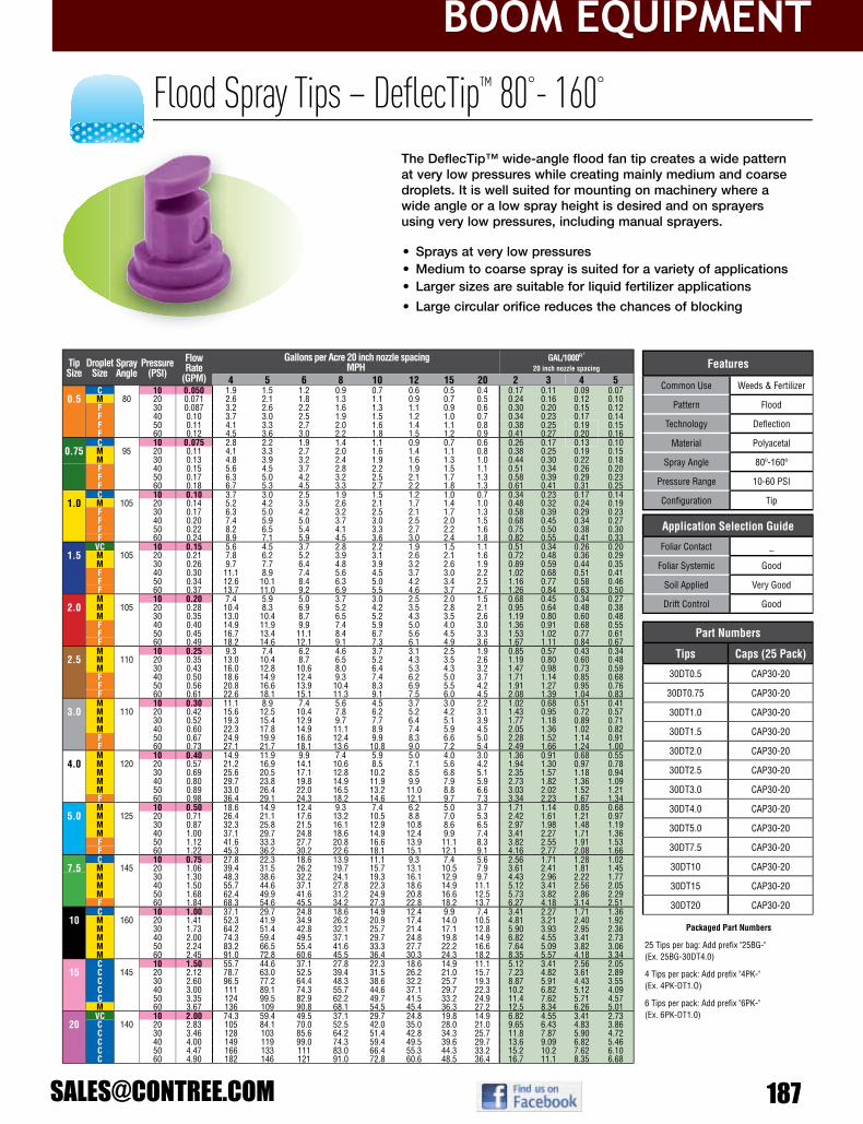
boom EquipmEnt
146
BROADCAST WIDE-AnGLE FLAT FAn
• Sprays at very low pressures• Medium to coarse spray is suited for a variety of applications• Larger sizes are suitable for liquid fertilizer applications
• Large circular orifice reduces the chances of blocking
The DeflecTip™ wide-angle flood fan tip creates a wide pattern at very low pressures while creating mainly medium and coarse droplets. It is well suited for mounting on machinery where a wide angle or a low spray height is desired and on sprayers using very low pressures, including manual sprayers.
Flood Spray Tips – DeflecTip™ 80°- 160°
Application Selection Guide
Foliar Contact _
Foliar Systemic Good
Soil Applied Very Good
Drift Control Good
Tip Size
DropletSize
Spray Angle
Pressure(PSI)
Flow Rate
(GPM)
Gallons per Acre 20 inch nozzle spacing MPH
GAL/1000Ft 2
20 inch nozzle spacing
4 5 6 8 10 12 15 20 2 3 4 5C 10 0.050 1.9 1.5 1.2 0.9 0.7 0.6 0.5 0.4 0.17 0.11 0.09 0.07
0.5 M 80 20 0.071 2.6 2.1 1.8 1.3 1.1 0.9 0.7 0.5 0.24 0.16 0.12 0.10F 30 0.087 3.2 2.6 2.2 1.6 1.3 1.1 0.9 0.6 0.30 0.20 0.15 0.12F 40 0.10 3.7 3.0 2.5 1.9 1.5 1.2 1.0 0.7 0.34 0.23 0.17 0.14F 50 0.11 4.1 3.3 2.7 2.0 1.6 1.4 1.1 0.8 0.38 0.25 0.19 0.15F 60 0.12 4.5 3.6 3.0 2.2 1.8 1.5 1.2 0.9 0.41 0.27 0.20 0.16C 10 0.075 2.8 2.2 1.9 1.4 1.1 0.9 0.7 0.6 0.26 0.17 0.13 0.10
0.75 M 95 20 0.11 4.1 3.3 2.7 2.0 1.6 1.4 1.1 0.8 0.38 0.25 0.19 0.15M 30 0.13 4.8 3.9 3.2 2.4 1.9 1.6 1.3 1.0 0.44 0.30 0.22 0.18F 40 0.15 5.6 4.5 3.7 2.8 2.2 1.9 1.5 1.1 0.51 0.34 0.26 0.20F 50 0.17 6.3 5.0 4.2 3.2 2.5 2.1 1.7 1.3 0.58 0.39 0.29 0.23F 60 0.18 6.7 5.3 4.5 3.3 2.7 2.2 1.8 1.3 0.61 0.41 0.31 0.25C 10 0.10 3.7 3.0 2.5 1.9 1.5 1.2 1.0 0.7 0.34 0.23 0.17 0.14
1.0 M 105 20 0.14 5.2 4.2 3.5 2.6 2.1 1.7 1.4 1.0 0.48 0.32 0.24 0.19F 30 0.17 6.3 5.0 4.2 3.2 2.5 2.1 1.7 1.3 0.58 0.39 0.29 0.23F 40 0.20 7.4 5.9 5.0 3.7 3.0 2.5 2.0 1.5 0.68 0.45 0.34 0.27F 50 0.22 8.2 6.5 5.4 4.1 3.3 2.7 2.2 1.6 0.75 0.50 0.38 0.30F 60 0.24 8.9 7.1 5.9 4.5 3.6 3.0 2.4 1.8 0.82 0.55 0.41 0.33
VC 10 0.15 5.6 4.5 3.7 2.8 2.2 1.9 1.5 1.1 0.51 0.34 0.26 0.201.5 M 105 20 0.21 7.8 6.2 5.2 3.9 3.1 2.6 2.1 1.6 0.72 0.48 0.36 0.29
M 30 0.26 9.7 7.7 6.4 4.8 3.9 3.2 2.6 1.9 0.89 0.59 0.44 0.35F 40 0.30 11.1 8.9 7.4 5.6 4.5 3.7 3.0 2.2 1.02 0.68 0.51 0.41F 50 0.34 12.6 10.1 8.4 6.3 5.0 4.2 3.4 2.5 1.16 0.77 0.58 0.46F 60 0.37 13.7 11.0 9.2 6.9 5.5 4.6 3.7 2.7 1.26 0.84 0.63 0.50M 10 0.20 7.4 5.9 5.0 3.7 3.0 2.5 2.0 1.5 0.68 0.45 0.34 0.27
2.0 M 105 20 0.28 10.4 8.3 6.9 5.2 4.2 3.5 2.8 2.1 0.95 0.64 0.48 0.38M 30 0.35 13.0 10.4 8.7 6.5 5.2 4.3 3.5 2.6 1.19 0.80 0.60 0.48F 40 0.40 14.9 11.9 9.9 7.4 5.9 5.0 4.0 3.0 1.36 0.91 0.68 0.55F 50 0.45 16.7 13.4 11.1 8.4 6.7 5.6 4.5 3.3 1.53 1.02 0.77 0.61F 60 0.49 18.2 14.6 12.1 9.1 7.3 6.1 4.9 3.6 1.67 1.11 0.84 0.67M 10 0.25 9.3 7.4 6.2 4.6 3.7 3.1 2.5 1.9 0.85 0.57 0.43 0.34
2.5 M 110 20 0.35 13.0 10.4 8.7 6.5 5.2 4.3 3.5 2.6 1.19 0.80 0.60 0.48M 30 0.43 16.0 12.8 10.6 8.0 6.4 5.3 4.3 3.2 1.47 0.98 0.73 0.59F 40 0.50 18.6 14.9 12.4 9.3 7.4 6.2 5.0 3.7 1.71 1.14 0.85 0.68F 50 0.56 20.8 16.6 13.9 10.4 8.3 6.9 5.5 4.2 1.91 1.27 0.95 0.76F 60 0.61 22.6 18.1 15.1 11.3 9.1 7.5 6.0 4.5 2.08 1.39 1.04 0.83M 10 0.30 11.1 8.9 7.4 5.6 4.5 3.7 3.0 2.2 1.02 0.68 0.51 0.41
3.0 M 110 20 0.42 15.6 12.5 10.4 7.8 6.2 5.2 4.2 3.1 1.43 0.95 0.72 0.57M 30 0.52 19.3 15.4 12.9 9.7 7.7 6.4 5.1 3.9 1.77 1.18 0.89 0.71M 40 0.60 22.3 17.8 14.9 11.1 8.9 7.4 5.9 4.5 2.05 1.36 1.02 0.82F 50 0.67 24.9 19.9 16.6 12.4 9.9 8.3 6.6 5.0 2.28 1.52 1.14 0.91F 60 0.73 27.1 21.7 18.1 13.6 10.8 9.0 7.2 5.4 2.49 1.66 1.24 1.00M 10 0.40 14.9 11.9 9.9 7.4 5.9 5.0 4.0 3.0 1.36 0.91 0.68 0.55
4.0 M 120 20 0.57 21.2 16.9 14.1 10.6 8.5 7.1 5.6 4.2 1.94 1.30 0.97 0.78M 30 0.69 25.6 20.5 17.1 12.8 10.2 8.5 6.8 5.1 2.35 1.57 1.18 0.94M 40 0.80 29.7 23.8 19.8 14.9 11.9 9.9 7.9 5.9 2.73 1.82 1.36 1.09M 50 0.89 33.0 26.4 22.0 16.5 13.2 11.0 8.8 6.6 3.03 2.02 1.52 1.21F 60 0.98 36.4 29.1 24.3 18.2 14.6 12.1 9.7 7.3 3.34 2.23 1.67 1.34M 10 0.50 18.6 14.9 12.4 9.3 7.4 6.2 5.0 3.7 1.71 1.14 0.85 0.68
5.0 M 125 20 0.71 26.4 21.1 17.6 13.2 10.5 8.8 7.0 5.3 2.42 1.61 1.21 0.97M 30 0.87 32.3 25.8 21.5 16.1 12.9 10.8 8.6 6.5 2.97 1.98 1.48 1.19M 40 1.00 37.1 29.7 24.8 18.6 14.9 12.4 9.9 7.4 3.41 2.27 1.71 1.36F 50 1.12 41.6 33.3 27.7 20.8 16.6 13.9 11.1 8.3 3.82 2.55 1.91 1.53F 60 1.22 45.3 36.2 30.2 22.6 18.1 15.1 12.1 9.1 4.16 2.77 2.08 1.66C 10 0.75 27.8 22.3 18.6 13.9 11.1 9.3 7.4 5.6 2.56 1.71 1.28 1.02
7.5 M 145 20 1.06 39.4 31.5 26.2 19.7 15.7 13.1 10.5 7.9 3.61 2.41 1.81 1.45M 30 1.30 48.3 38.6 32.2 24.1 19.3 16.1 12.9 9.7 4.43 2.96 2.22 1.77M 40 1.50 55.7 44.6 37.1 27.8 22.3 18.6 14.9 11.1 5.12 3.41 2.56 2.05M 50 1.68 62.4 49.9 41.6 31.2 24.9 20.8 16.6 12.5 5.73 3.82 2.86 2.29F 60 1.84 68.3 54.6 45.5 34.2 27.3 22.8 18.2 13.7 6.27 4.18 3.14 2.51C 10 1.00 37.1 29.7 24.8 18.6 14.9 12.4 9.9 7.4 3.41 2.27 1.71 1.36
10 M 160 20 1.41 52.3 41.9 34.9 26.2 20.9 17.4 14.0 10.5 4.81 3.21 2.40 1.92M 30 1.73 64.2 51.4 42.8 32.1 25.7 21.4 17.1 12.8 5.90 3.93 2.95 2.36M 40 2.00 74.3 59.4 49.5 37.1 29.7 24.8 19.8 14.9 6.82 4.55 3.41 2.73M 50 2.24 83.2 66.5 55.4 41.6 33.3 27.7 22.2 16.6 7.64 5.09 3.82 3.06M 60 2.45 91.0 72.8 60.6 45.5 36.4 30.3 24.3 18.2 8.35 5.57 4.18 3.34C 10 1.50 55.7 44.6 37.1 27.8 22.3 18.6 14.9 11.1 5.12 3.41 2.56 2.05
15 C 145 20 2.12 78.7 63.0 52.5 39.4 31.5 26.2 21.0 15.7 7.23 4.82 3.61 2.89C 30 2.60 96.5 77.2 64.4 48.3 38.6 32.2 25.7 19.3 8.87 5.91 4.43 3.55C 40 3.00 111 89.1 74.3 55.7 44.6 37.1 29.7 22.3 10.2 6.82 5.12 4.09C 50 3.35 124 99.5 82.9 62.2 49.7 41.5 33.2 24.9 11.4 7.62 5.71 4.57M 60 3.67 136 109 90.8 68.1 54.5 45.4 36.3 27.2 12.5 8.34 6.26 5.01VC 10 2.00 74.3 59.4 49.5 37.1 29.7 24.8 19.8 14.9 6.82 4.55 3.41 2.73
20 C 140 20 2.83 105 84.1 70.0 52.5 42.0 35.0 28.0 21.0 9.65 6.43 4.83 3.86C 30 3.46 128 103 85.6 64.2 51.4 42.8 34.3 25.7 11.8 7.87 5.90 4.72C 40 4.00 149 119 99.0 74.3 59.4 49.5 39.6 29.7 13.6 9.09 6.82 5.46C 50 4.47 166 133 111 83.0 66.4 55.3 44.3 33.2 15.2 10.2 7.62 6.10C 60 4.90 182 146 121 91.0 72.8 60.6 48.5 36.4 16.7 11.1 8.35 6.68
Features
Common Use Weeds & Fertilizer
Pattern Flood
Technology Defl ection
Material Polyacetal
Spray Angle 80º-160º
Pressure Range 10-60 PSI
Confi guration Tip
Part numbers
Tips Caps (25 Pack)
30DT0.5 CAP30-20
30DT0.75 CAP30-20
30DT1.0 CAP30-20
30DT1.5 CAP30-20
30DT2.0 CAP30-20
30DT2.5 CAP30-20
30DT3.0 CAP30-20
30DT4.0 CAP30-20
30DT5.0 CAP30-20
30DT7.5 CAP30-20
30DT10 CAP30-20
30DT15 CAP30-20
30DT20 CAP30-20
Packaged Part numbers
25 Tips per bag: Add prefi x "25BG-"(Ex. 25BG-30DT4.0)
4 Tips per pack: Add prefi x "4PK-"(Ex. 4PK-DT1.O)
6 Tips per pack: Add prefi x "6PK-"(Ex. 6PK-DT1.0)

boom EquipmEnt
188 800-433-3579
152
• Six streams distribute fertilizer more evenly than one single stream
• Reduced atomization limits leaf burn and scorching• Wear-resistant Albuz® ceramic orifice• FastCap® includes tip, cap and gasket
The ESI six stream tip is ideal for applying fertilizer into soil seeded crops. It creates six individual streams that distribute the fertilizer on the soil while getting less on the crop. The Albuz® ceramic metering orifice and unique low pressure distribution chamberkeep the streams stable to reduce atomization and prevent leaf burn and scorching. Spacing and spray height is similar to 110° broadcast tips.
Stream Spray Tips – Ceramic ESI Six Stream
Application Selection Guide
Foliar Contact –
Foliar Systemic –
Soil Applied Excellent
Drift Control Excellent
TipSize
Pressure(PSI)
Flow Rate
(GPM)
Gallons per Acre 20 inch nozzle spacing MPH
GAL/1000Ft 2
20 inch nozzle spacing
4 5 6 8 10 12 15 20 2 3 4 515 0.09 6.7 5.3 4.5 3.3 2.7 2.2 1.8 1.3 0.31 0.20 0.15 0.1220 0.11 8.2 6.5 5.4 4.1 3.3 2.7 2.2 1.6 0.38 0.25 0.19 0.15
015 30 0.13 9.7 7.7 6.4 4.8 3.9 3.2 2.6 1.9 0.44 0.30 0.22 0.1840 0.15 11.1 8.9 7.4 5.6 4.5 3.7 3.0 2.2 0.51 0.34 0.26 0.2050 0.17 12.6 10.1 8.4 6.3 5.0 4.2 3.4 2.5 0.58 0.39 0.29 0.2360 0.18 13.4 10.7 8.9 6.7 5.3 4.5 3.6 2.7 0.61 0.41 0.31 0.2515 0.12 8.9 7.1 5.9 4.5 3.6 3.0 2.4 1.8 0.41 0.27 0.20 0.1620 0.14 10.4 8.3 6.9 5.2 4.2 3.5 2.8 2.1 0.48 0.32 0.24 0.1930 0.17 12.6 10.1 8.4 6.3 5.0 4.2 3.4 2.5 0.58 0.39 0.29 0.23
02 40 0.20 14.9 11.9 9.9 7.4 5.9 5.0 4.0 3.0 0.68 0.45 0.34 0.2750 0.22 16.3 13.1 10.9 8.2 6.5 5.4 4.4 3.3 0.75 0.50 0.38 0.3060 0.24 17.8 14.3 11.9 8.9 7.1 5.9 4.8 3.6 0.82 0.55 0.41 0.3315 0.15 11.1 8.9 7.4 5.6 4.5 3.7 3.0 2.2 0.51 0.34 0.26 0.2020 0.18 13.4 10.7 8.9 6.7 5.3 4.5 3.6 2.7 0.61 0.41 0.31 0.25
025 30 0.22 16.3 13.1 10.9 8.2 6.5 5.4 4.4 3.3 0.75 0.50 0.38 0.3040 0.25 18.6 14.9 12.4 9.3 7.4 6.2 5.0 3.7 0.85 0.57 0.43 0.3450 0.28 20.8 16.6 13.9 10.4 8.3 6.9 5.5 4.2 0.95 0.64 0.48 0.3860 0.31 23.0 18.4 15.3 11.5 9.2 7.7 6.1 4.6 1.06 0.70 0.53 0.4215 0.18 13.4 10.7 8.9 6.7 5.3 4.5 3.6 2.7 0.61 0.41 0.31 0.2520 0.21 15.6 12.5 10.4 7.8 6.2 5.2 4.2 3.1 0.72 0.48 0.36 0.29
03 30 0.26 19.3 15.4 12.9 9.7 7.7 6.4 5.1 3.9 0.89 0.59 0.44 0.3540 0.30 22.3 17.8 14.9 11.1 8.9 7.4 5.9 4.5 1.02 0.68 0.51 0.4150 0.34 25.2 20.2 16.8 12.6 10.1 8.4 6.7 5.0 1.16 0.77 0.58 0.4660 0.37 27.5 22.0 18.3 13.7 11.0 9.2 7.3 5.5 1.26 0.84 0.63 0.5015 0.24 17.8 14.3 11.9 8.9 7.1 5.9 4.8 3.6 0.82 0.55 0.41 0.3320 0.28 20.8 16.6 13.9 10.4 8.3 6.9 5.5 4.2 0.95 0.64 0.48 0.38
04 30 0.35 26.0 20.8 17.3 13.0 10.4 8.7 6.9 5.2 1.19 0.80 0.60 0.4840 0.40 29.7 23.8 19.8 14.9 11.9 9.9 7.9 5.9 1.36 0.91 0.68 0.5550 0.45 33.4 26.7 22.3 16.7 13.4 11.1 8.9 6.7 1.53 1.02 0.77 0.6160 0.49 36.4 29.1 24.3 18.2 14.6 12.1 9.7 7.3 1.67 1.11 0.84 0.6715 0.31 23.0 18.4 15.3 11.5 9.2 7.7 6.1 4.6 1.06 0.70 0.53 0.4220 0.35 26.0 20.8 17.3 13.0 10.4 8.7 6.9 5.2 1.19 0.80 0.60 0.48
05 30 0.43 31.9 25.5 21.3 16.0 12.8 10.6 8.5 6.4 1.47 0.98 0.73 0.5940 0.50 37.1 29.7 24.8 18.6 14.9 12.4 9.9 7.4 1.71 1.14 0.85 0.6850 0.56 41.6 33.3 27.7 20.8 16.6 13.9 11.1 8.3 1.91 1.27 0.95 0.7660 0.61 45.3 36.2 30.2 22.6 18.1 15.1 12.1 9.1 2.08 1.39 1.04 0.8315 0.37 27.5 22.0 18.3 13.7 11.0 9.2 7.3 5.5 1.26 0.84 0.63 0.5020 0.42 31.2 24.9 20.8 15.6 12.5 10.4 8.3 6.2 1.43 0.95 0.72 0.57
06 30 0.52 38.6 30.9 25.7 19.3 15.4 12.9 10.3 7.7 1.77 1.18 0.89 0.7140 0.60 44.6 35.6 29.7 22.3 17.8 14.9 11.9 8.9 2.05 1.36 1.02 0.8250 0.67 49.7 39.8 33.2 24.9 19.9 16.6 13.3 9.9 2.28 1.52 1.14 0.9160 0.73 54.2 43.4 36.1 27.1 21.7 18.1 14.5 10.8 2.49 1.66 1.24 1.0015 0.49 36.4 29.1 24.3 18.2 14.6 12.1 9.7 7.3 1.67 1.11 0.84 0.6720 0.57 42.3 33.9 28.2 21.2 16.9 14.1 11.3 8.5 1.94 1.30 0.97 0.78
08 30 0.69 51.2 41.0 34.2 25.6 20.5 17.1 13.7 10.2 2.35 1.57 1.18 0.9440 0.80 59.4 47.5 39.6 29.7 23.8 19.8 15.8 11.9 2.73 1.82 1.36 1.0950 0.89 66.1 52.9 44.1 33.0 26.4 22.0 17.6 13.2 3.03 2.02 1.52 1.2160 0.98 72.8 58.2 48.5 36.4 29.1 24.3 19.4 14.6 3.34 2.23 1.67 1.3415 0.61 45.3 36.2 30.2 22.6 18.1 15.1 12.1 9.1 2.08 1.39 1.04 0.8320 0.71 52.7 42.2 35.1 26.4 21.1 17.6 14.1 10.5 2.42 1.61 1.21 0.97
10 30 0.87 64.6 51.7 43.1 32.3 25.8 21.5 17.2 12.9 2.97 1.98 1.48 1.1940 1.00 74.3 59.4 49.5 37.1 29.7 24.8 19.8 14.9 3.41 2.27 1.71 1.3650 1.12 83.2 66.5 55.4 41.6 33.3 27.7 22.2 16.6 3.82 2.55 1.91 1.5360 1.22 90.6 72.5 60.4 45.3 36.2 30.2 24.2 18.1 4.16 2.77 2.08 1.6615 0.92 68.3 54.6 45.5 34.2 27.3 22.8 18.2 13.7 3.14 2.09 1.57 1.2520 1.06 78.7 63.0 52.5 39.4 31.5 26.2 21.0 15.7 3.61 2.41 1.81 1.4530 1.30 96.5 77.2 64.4 48.3 38.6 32.2 25.7 19.3 4.43 2.96 2.22 1.77
15 40 1.50 111 89.1 74.3 55.7 44.6 37.1 29.7 22.3 5.12 3.41 2.56 2.0550 1.68 125 99.8 83.2 62.4 49.9 41.6 33.3 24.9 5.73 3.82 2.86 2.2960 1.84 137 109 91.1 68.3 54.6 45.5 36.4 27.3 6.27 4.18 3.14 2.51
20
15 1.22 90.6 72.5 60.4 45.3 36.2 30.2 24.2 18.1 4.16 2.77 2.08 1.6620 1.41 105 83.8 69.8 52.3 41.9 34.9 27.9 20.9 4.81 3.21 2.40 1.9230 1.73 128 103 85.6 64.2 51.4 42.8 34.3 25.7 5.90 3.93 2.95 2.3640 2.00 149 119 99.0 74.3 59.4 49.5 39.6 29.7 6.82 4.55 3.41 2.7350 2.24 166 133 111 83.2 66.5 55.4 44.4 33.3 7.64 5.09 3.82 3.0660 2.45 182 146 121 91.0 72.8 60.6 48.5 36.4 8.35 5.57 4.18 3.34
Features
Common Use Fertilizer
Pattern Streams
Technology Pre-Orifi ce
Material Ceramic
Spray Angle 110º Equivalent
Pressure Range 15-60 PSI
Confi guration Tip, FastCap
Part Numbers
Tips 110º FastCaps 110º
ESI-110015 FC-ESI-110015
ESI-11002 FC-ESI-11002
ESI-110025 FC-ESI-110025
ESI-11003 FC-ESI-11003
ESI-11004 FC-ESI-11004
ESI-11005 FC-ESI-11005
ESI-11006 FC-ESI-11006
– FC-ESI-11008
– FC-ESI-11010
– FC-ESI-11015
– FC-ESI-11020P
Replacement Cap Gasket
22W11MF64 Flat seal (sizes 015-06)
65-BS205 O-ring (sizes 08-15)
We carry the full line up of Hypro products!If you don’t see the part listed that you need just contact us and we can order it for you.
Contact one of our sales team members1-800-433-3579 or [email protected]

boom EquipmEnt
154
Flow Regulating Discs – DC & Ceramic AMT 0ºDC – Flow Regulating Disc
The Hypro® DC regulates flow and produces a straight stream pattern. Precision-molded in polyacetal.
AMT – Ceramic Flow Regulating Disc
The Albuz® ceramic disc regulates flow and produces a straight stream pattern. Precision-molded in ceramic. Turning the disc over provides a different flow.
“w” “n”
Application Selection GuideFoliar Contact –
Foliar Systemiic –
Soil Applied Very Good
Drift Control Very Good
DiscUS Gallon/Min
PSI10 15 20 25 30 35 40 60 80 100 150
30-DC-00 0 0 0 0 0 0 0 0 0 0 030-DC010 0.008 0.010 0.011 0.013 0.014 0.015 0.016 0.020 0.023 0.025 0.03130-DC018 0.030 0.037 0.042 0.047 0.052 0.056 0.060 0.073 0.085 0.095 0.11630-DC023 0.038 0.047 0.054 0.060 0.066 0.071 0.076 0.093 0.107 0.120 0.14730-DC-01 0.057 0.070 0.081 0.090 0.099 0.107 0.114 0.140 0.161 0.180 0.221
30-DC-015 0.078 0.096 0.110 0.123 0.135 0.146 0.156 0.191 0.221 0.247 0.30230-DC-02 0.105 0.129 0.148 0.166 0.182 0.196 0.210 0.257 0.297 0.332 0.40730-DC-03 0.133 0.163 0.188 0.210 0.230 0.249 0.266 0.326 0.376 0.421 0.515
30-DC-035 0.175 0.214 0.247 0.277 0.303 0.327 0.350 0.429 0.495 0.553 0.67830-DC-04 0.242 0.296 0.342 0.383 0.419 0.453 0.484 0.593 0.684 0.765 0.93730-DC-05 0.392 0.480 0.554 0.620 0.679 0.733 0.784 0.960 1.11 1.24 1.5230-DC-06 0.570 0.698 0.806 0.901 0.987 1.07 1.14 1.40 1.61 1.80 2.2130-DC-07 0.760 0.931 1.07 1.20 1.32 1.42 1.52 1.86 2.15 2.40 2.9430-DC-08 0.960 1.18 1.36 1.52 1.66 1.80 1.92 2.35 2.72 3.04 3.7230-DC-10 1.55 1.90 2.19 2.45 2.68 2.90 3.10 3.80 4.38 4.90 6.00
30-DC-12 2.20 2.69 3.11 3.48 3.81 4.12 4.40 5.39 6.22 6.96 8.52
Part Numbers
Tips
30-DC-00
30-DC010
30-DC018
30-DC023
30-DC-01
30-DC-015
30-DC-02
30-DC-03
30-DC-035
30-DC-04
30-DC-05
30-DC-06
30-DC-07
30-DC-08
30-DC-10
30-DC-12
Application Selection Guide
Foliar Contact –
Foliar Systemiic –
Soil Applied Very Good
Drift Control Very Good
Features
Common Use Fertilizer
Pattern Stream
Technology Round Orifi ce
Material Ceramic
Spray Angle 0º
Pressure Range 10-725 PSI
Confi guration Disc
Part Numbers
Tips
AMT-15007
AMT-15008
AMT-15010
AMT-15012
AMT-15015
AMT-15018
AMT-15020
AMT-15023
DiscUS Gallon/Min
PSI10 15 20 25 30 35 40 60 80 100 150 200 300 725
AMT-15007 (n) 0.063 0.077 0.088 0.099 0.108 0.117 0.125 0.153 0.177 0.198 0.242 0.280 0.342 0.532AMT-15007 (w) 0.064 0.078 0.091 0.101 0.111 0.120 0.128 0.157 0.181 0.202 0.248 0.286 0.351 0.545AMT-15008 (n) 0.066 0.080 0.093 0.104 0.113 0.123 0.131 0.160 0.185 0.207 0.254 0.293 0.359 0.558AMT-15008 (w) 0.083 0.101 0.117 0.130 0.143 0.154 0.165 0.202 0.233 0.261 0.320 0.369 0.452 0.702AMT-15010 (n) 0.099 0.121 0.140 0.157 0.171 0.185 0.198 0.242 0.280 0.313 0.383 0.443 0.542 0.843AMT-15010 (w) 0.139 0.170 0.197 0.220 0.241 0.260 0.278 0.340 0.393 0.440 0.538 0.622 0.761 1.18AMT-15012 (n) 0.144 0.176 0.203 0.227 0.249 0.268 0.287 0.352 0.406 0.454 0.556 0.642 0.786 1.22AMT-15012 (w) 0.174 0.213 0.246 0.275 0.301 0.326 0.348 0.426 0.492 0.550 0.674 0.778 0.953 1.48AMT-15015 (n) 0.217 0.265 0.306 0.342 0.375 0.405 0.433 0.530 0.612 0.685 0.839 0.968 1.19 1.84AMT-15015 (w) 0.287 0.351 0.405 0.453 0.496 0.536 0.573 0.702 0.810 0.906 1.11 1.28 1.57 2.44AMT-15018 (n) 0.302 0.370 0.427 0.478 0.523 0.565 0.604 0.740 0.854 0.955 1.17 1.35 1.65 2.57AMT-15020 (n) 0.375 0.459 0.530 0.593 0.650 0.702 0.750 0.919 1.06 1.19 1.45 1.68 2.05 3.19AMT-15018 (w) 0.388 0.475 0.548 0.613 0.671 0.725 0.775 0.949 1.10 1.23 1.50 1.73 2.12 3.30AMT-15020 (w) 0.472 0.577 0.667 0.746 0.817 0.882 0.943 1.15 1.33 1.49 1.83 2.11 2.58 4.01AMT-15023 (n) 0.485 0.594 0.686 0.767 0.840 0.907 0.970 1.19 1.37 1.53 1.88 2.17 2.66 4.13AMT-15023 (w) 0.605 0.741 0.856 0.957 1.05 1.13 1.21 1.48 1.71 1.91 2.34 2.71 3.31 5.15
w - Numbers can be read on face of disc when installed in capn - Numbers on disc cannot be read when installed in capPhotos above show the disc exit side.
Features
Common Use FertilizerPattern Stream
Technology Round Orifi ceMaterial Polyacetal
Spray Angle 0ºPressure Range 10-150 PSIConfi guration Disc
188
Reference # Part # Description Packaging
- 4200-0015N 1⁄4" BSP x Quick Attach None
1 4200-0016N 1⁄4" MNPT x Quick Attach None
2 4200N-0017 45º Double Elbow w/Gasket 10/ Bag, Priced Individually
3 4200N-0018 90º Elbow x Quick Attach 10/ Bag, Priced Individually
4 4200-0019 1⁄4" FNPT x Quick Attach None
5 9950-0024 Hardi* Adapter 10/ Bag, Priced Per Bag
6 9950-0027 Jacto** Adapter 10/ Bag, Priced Per Bag
- BG-400275N 1⁄4" FNPT x Quick Attach 1/Bag
Quick Fitting Adapters
Nozzle Body Accessories & Foam Marker
Part number Material Piping/Tubing O.D.413003* Steel 3⁄4” Round Pipe (1.050”)413004* Steel 1” Round Pipe (1.315”)413005* Steel 1-1⁄4” Round Pipe (1.660”)413013 Steel 3⁄4” Square Tubing413014 Steel 1” Square Tubing413015 Steel 1-1⁄4” Square Tubing413016 Steel 1-1⁄2” Square Tubing413018 304 Stainless Steel 1-1⁄2” Square Tubing
Part number Material Piping/Tubing O.D.1520-1075 zinc plated steel 3/4" square tubing1520-1100 zinc plated steel 1" square tubing1520-1125 zinc plated steel 1-1⁄4”" square tubing1520-1150 zinc plated steel 1-1⁄2" square tubing
1520-1075SS 304 stainless steel 3/4" square tubing1520-1100SS 304 stainless steel 1" square tubing1520-1125SS 304 stainless steel 1-1⁄4”" square tubing1520-1150SS 304 stainless steel 1-1⁄2" square tubing
Vari-Spacing Clamps
ProFlo™ Dry Boom Clamps with Slot for Easy Assembly- Boxes of 100
Steel Boom Clamps for use with 11/16” nozzle BodiesPart number Description
BC34R* 3⁄4” Round Pipe BC100R* 1” Round Pipe
BC100 1” SquareBC114 1-1⁄4” Square
* Dimensions refer to I.D. (inner diameter).
* By pipe, dimensions refer to I.D. (inner diameter).
Add Prefi x ''BG-" for 1 part per retail bag
Add Prefi x ''BG-" for 1 part per retail bag
* Hardi is a registered trademark of Hardi International A/S** Jacto is a registered trademark of Jacto, Inc.
1
2
5
4
3
6
188
Part number Material Piping/Tubing O.D.413003* Steel 3⁄4” Round Pipe (1.050”)413004* Steel 1” Round Pipe (1.315”)413005* Steel 1-1⁄4” Round Pipe (1.660”)413013 Steel 3⁄4” Square Tubing413014 Steel 1” Square Tubing413015 Steel 1-1⁄4” Square Tubing413016 Steel 1-1⁄2” Square Tubing413018 304 Stainless Steel 1-1⁄2” Square Tubing
Part number Material Piping/Tubing O.D.1520-1075 zinc plated steel 3/4" square tubing1520-1100 zinc plated steel 1" square tubing1520-1125 zinc plated steel 1-1⁄4”" square tubing1520-1150 zinc plated steel 1-1⁄2" square tubing
1520-1075SS 304 stainless steel 3/4" square tubing1520-1100SS 304 stainless steel 1" square tubing1520-1125SS 304 stainless steel 1-1⁄4”" square tubing1520-1150SS 304 stainless steel 1-1⁄2" square tubing
Vari-Spacing Clamps
ProFlo™ Dry Boom Clamps with Slot for Easy Assembly- Boxes of 100
Steel Boom Clamps for use with 11/16” nozzle BodiesPart number Description
BC34R* 3⁄4” Round Pipe BC100R* 1” Round Pipe
BC100 1” SquareBC114 1-1⁄4” Square
* Dimensions refer to I.D. (inner diameter).
* By pipe, dimensions refer to I.D. (inner diameter).
Add Prefi x ''BG-" for 1 part per retail bag
Add Prefi x ''BG-" for 1 part per retail bag

boom EquipmEnt
190 800-433-3579
Hollow Cone Spray Tips – SwirlTip™ Disc & Cores 25º-110ºThe Hypro® SwirlTip™ disc and core hollow-cone spray tips produce finely atomized droplets in a hollow-cone pattern.
Disc Core
DC/CR Disc Core
Application Selection Guide
Foliar Contact Very Good
Foliar Systemiic Good
Soil Applied –
Drift Control –
DiscUS Gallon/Min
Spray Angleat 40 PSI
ColorDisc/Core
PSICore 10 20 30 40 60 80 100 150
30-DC-01 30-CR-13 50 Gray/Red - - 0.06 0.07 0.08 0.09 0.10 0.1330-DC-015 30-CR-13 55 Black/Red - - 0.06 0.07 0.09 0.10 0.11 0.1430-DC-02 30-CR-13 65 Brown/Red - 0.06 0.07 0.08 0.10 0.12 0.13 0.1630-DC-03 30-CR-13 70 Orange/Red - 0.06 0.08 0.09 0.11 0.12 0.14 0.1730-DC-04 30-CR-13 80 Red/Red 0.06 0.08 0.10 0.12 0.14 0.17 0.19 0.2330-DC-01 30-CR-23 45 Gray/LightBlue - - 0.06 0.07 0.09 0.10 0.11 0.1430-DC-015 30-CR-23 50 Black/LightBlue - - 0.07 0.09 0.10 0.12 0.13 0.1630-DC-02 30-CR-23 70 Brown/LightBlue - 0.08 0.09 0.11 0.13 0.15 0.17 0.2130-DC-03 30-CR-23 70 Orange/LightBlue 0.06 0.08 0.10 0.12 0.14 0.16 0.18 0.2230-DC-04 30-CR-23 80 Red/LightBlue 0.08 0.11 0.13 0.15 0.19 0.22 0.24 0.3030-DC-05 30-CR-23 90 Blue/LightBlue 0.09 0.13 0.16 0.18 0.22 0.25 0.28 0.3530-DC-06 30-CR-23 90 Yellow/LightBlue 0.10 0.15 0.18 0.21 0.25 0.29 0.33 0.4030-DC-01 30-CR-25 25 Gray/Yellow - - 0.09 0.10 0.12 0.14 0.16 0.1930-DC-015 30-CR-25 40 Black/Yellow - - 0.11 0.13 0.16 0.19 0.21 0.2630-DC-02 30-CR-25 50 Brown/Yellow - 0.11 0.13 0.16 0.19 0.22 0.25 0.3030-DC-03 30-CR-25 60 Orange/Yellow 0.09 0.13 0.16 0.19 0.23 0.27 0.30 0.3630-DC-04 30-CR-25 75 Red/Yellow 0.14 0.19 0.24 0.28 0.34 0.39 0.43 0.5330-DC-05 30-CR-25 80 Blue/Yellow 0.18 0.25 0.30 0.35 0.43 0.49 0.55 0.68 30-DC-06 30-CR-25 85 Yellow/Yellow 0.23 0.32 0.39 0.45 0.55 0.64 0.71 0.8730-DC-07 30-CR-25 90 Green/Yellow 0.25 0.35 0.43 0.50 0.61 0.71 0.79 0.9730-DC -08 30-CR-25 95 White/Yellow 0.30 0.42 0.52 0.60 0.73 0.85 0.95 1.1630-DC-10 30-CR-25 100 LimeGreen/Yellow 0.38 0.53 0.65 0.75 0.92 1.06 1.19 1.4530-DC-12 30-CR-25 110 RoyalBlue/Yellow 0.46 0.65 0.80 0.93 1.13 1.31 1.46 1.7930-DC-01 30-CR-45 25 Gray/Green - - - 0.12 0.15 0.17 0.19 0.2330-DC-015 30-CR-45 35 Black/Green - - 0.14 0.16 0.20 0.23 0.25 0.3130-DC-02 30-CR-45 45 Brown/Green - 0.14 0.17 0.20 0.24 0.28 0.32 0.3930-DC-03 30-CR-45 55 Orange/Green - 0.16 0.20 0.23 0.28 0.32 0.36 0.4430-DC-04 30-CR-45 70 Red/Green 0.18 0.25 0.30 0.35 0.43 0.49 0.55 0.6830-DC-05 30-CR-45 75 Blue/Green 0.23 0.32 0.39 0.45 0.55 0.64 0.71 0.8730-DC-06 30-CR-45 80 Yellow/Green 0.29 0.41 0.50 0.58 0.70 0.81 0.91 1.1130-DC-07 30-CR-45 85 Green/Green 0.34 0.48 0.58 0.68 0.83 0.95 1.07 1.3130-DC-08 30-CR-45 90 White/Green 0.41 0.58 0.71 0.83 1.01 1.17 1.30 1.6030-DC-10 30-CR-45 95 LimeGreen/Green 0.55 0.78 0.95 1.10 1.35 1.56 1.74 2.1330-DC-12 30-CR-45 100 RoyalBlue/Green 0.67 0.95 1.16 1.34 1.64 1.90 2.12 2.60
Features
Common Use Plant Health
Pattern Hollow Cone
Technology Swirl
Material Polyacetal
Spray Angle 25º - 110º
Pressure Range 10-150 PSI
Confi guration Tip
Part Numbers
Discs Cores
30-DC-01 30-CR-13
30-DC-015 30-CR-23
30-DC-02 30-CR-25
30-DC-03 30-CR-45
30-DC-04 –
30-DC-05 –
30-DC-06 –
30-DC-07 –
30-DC-08 –
30-DC-10 –
30-DC-12 –

boom EquipmEnt
Spray Tip Caps, Adapters
ISO Standard Fan
Defl ect Tipno-offset
European Fan(Thick body)
Standard Round(non-aligning)
Albuz® Round(Thick fl ange)
Shut-off Threaded
Fits:
ULD, GA, LD, VP,
TR, OC, F, E, AXI, ADI, OCI
DT, PoliJet AVI, AVI-TWIn,ESI, APG, APE
HCX, FCXDC/CR, HAF, APMfl anged hose barbs
Ceramic Disc, ATR, HCA, TVI Blank 1/4”FnPT Std.
Pack
Black CAP00-20 CAP30-20 CAP01-20 CAP04-20 CAP05-20 CAP09-20 CAP10-20 25
Orange CAP00-01 - CAP01-01 CAP04-01 CAP05-01 - - 25
Green CAP00-015 - CAP01-015 CAP04-015 CAP05-015 - - 25
Yellow CAP00-02 - CAP01-02 CAP04-02 CAP05-02 - - 25
Lilac CAP00-025 - CAP01-025 CAP04-025 CAP05-025 - - 25
Blue CAP00-03 - CAP01-03 CAP04-03 CAP05-03 - - 25
Dark Red CAP00-035 - - - - - - 25
Red CAP00-04 - CAP01-04 CAP04-04 CAP05-04 - - 25
Brown CAP00-05 - CAP01-05 CAP04-05 CAP05-05 - - 25
Gray CAP00-06 - CAP01-06 CAP04-06 CAP05-06 - - 25
White CAP00-08 - CAP01-08 CAP04-08 CAP05-08 - - 25
Light Blue CAP00-10 - CAP01-10 CAP04-10 - - - 25
Lime Green CAP00-15 - CAP01-15 CAP04-15 - - - 25Included EPDM seal 22W11MF64 22W11MF64 22W11MF64 22W11MF64 22W11MF64 - 22W11MF64 -Included nitrile seal - - - - - 65-BS205 - -Separate Viton seal 22W11MF64V 22W11MF64V 22W11MF64V 22W11MF64V 22W11MF64V 65-VBS205 22W11MF64V -
Part # Description4200N-0017 45 Double w/ Gasket 4200N-0018 90 Elbow w/ Gasket2270-0136 Cap Filler Disk
Part # Description4200N-0060 1/4" Push-to-Connect Outlet4200N-0061 3/8" Push-to-Connect Outlet
Elbow and Double Adapters for Spray Tip Cap
Push-to-Connect Spray Caps
Elbow and Double Adapters for Spray Tip Cap
Part # Adapters For Description9950-0024 Hardi* 10 pack of adapters for converting nozzle
body to accept Hypro cap9950-0027 Jacto**
Hardi and Jacto Adapters
* Hardi is a registered trademark of Hardi International A/S.** Jacto is a registered trademark of Jacto Inc.
Hypro caps provide trouble-free spray tip installation and sealing on Hypro ProFlo nozzle bodies and several other common makes.
• Color-coded to ISO standards for nozzle flow to simplify tip selection and identification in the field
• Available in configurations optimized to fit a variety of spray tip geometries
• Caps for fan pattern tips automatically align tips for enhanced spray uniformity
Albuz® Round Shut-offEuropean Fan Standard RoundISO Standard Defl ect Tip Threaded

boom EquipmEnt
192 800-433-3579183183
FEATURES• Three turret styles for an easy change of spray tips:
single, 3-way, and 5-way
• Provides lowest pressure drop at any given flow in the industry
• 2.6 gpm (9.84 LPM) with a 5 psi (.345 BAR) pressure drop
• Available in wet or dry boom versions
• Positive shutoff between each spray position
• Custom logos available upon request (minimum quantities apply)
ProFlo Nozzle Body Performance Curve
0.0
1.0
2.0
3.0
4.0
5.0
0 5 10 15Pressure drop (psi)
Flow
(gal
/min
)
0.0
4.0
8.0
12.0
16.0
0.0 0.2 0.4 0.6 0.8 1.0Pressure drop (bar)
Flow
(l/m
in)
BEnEFITS • Designed to deliver the highest flow rates across the
spraying pressure range
• Unique DCV (diaphragm check valve) design reduces restrictions in the flow path, enabling 2.6 gpm with a 5 psi pressure drop through the nozzle
• Supports faster field speeds with the same coverage and supports direct fertilizer application through the nozzle body DCV flow path
• Turret-indexing design provides improved consistency and reliability throughout the life of the nozzle body – eliminating free spinning and seizing problems seen on competitive nozzle bodies
• Automatic spray alignment using flat fan spray tips
• Compact design makes mounting easier with less potential interference with the spray boom structure
• ProFlo nozzle bodies come standard with an 8 psi (.55 bar) diaphragm check valve. 4 psi, 12 psi, 20 psi, and 25 psi checks are available as options.
FEATURESFEATURES
Creates a cleaner looking plumbing system by eliminating the need for an extra fitting at the end of the boom
Optional cleanout port for easy boom flushing
Eliminates trapped air from the boom by allowing air to escape through the nozzle body, reducing nozzle turn-off time by 85%
Terminates the pipe at the last nozzle body, eliminating six inches of dead-ends from each pipe end and reducing pipe costs by 10%
Conventional boom designs trap air in the boom causing a delay from the close signal to when spray actually stops. Hypro’s Express nozzle body end caps include a passive feature that eliminates the trapped air by allowing the air to escape through the nozzle body. When the boom is completely filled with liquid, the nozzle body’s diaphragm check valve (DCV) activation time is greatly improved, by as much as 85%. The Express nozzle body end cap supports today’s practice of Precision Agriculture by enabling standard nozzle bodies to have much quicker reaction times in response to GPS boom shut-off control signals, turning off spray quickly and decisively on overlaps, end rows, and boundary areas.
The Express nozzle body end caps also create a much cleaner look by terminating the pipe at the last nozzle body, while reducing pipe material by as much as 10%. Using nozzle body end caps will contribute to better boom hygiene by eliminating the ‘dead-end’ termination of pipe that allows chemical residue to build up and air to accumulate. The additional option of a removable end plug allows easy access for boom cleanout to flush debris from boom pipe.
Express™ Nozzle Body End Caps
See page 186 for order information

boom EquipmEnt
We carry the full line up of Hypro products!If you don’t see the part listed that you need just contact us and we can order it for you.
Contact one of our sales team members1-800-433-3579 or [email protected]
182
3 and 5-Way nozzle Bodies for Wet Boom (no tab for boom clamp) Seal Option/
Housing ReferenceTurret
Options(to clamp on) Pipe Size
1⁄2" 3⁄4" 1" 20mm 25mm
EPDM/Red 3 4223N-B322 4223N-B323 4223N-B324 4223N-B327 4223N-B3285 4223N-B522 4223N-B523 4223N-B524 4223N-B527 4223N-B528
Viton/Green 3 4223N-B322V 4223N-B323V 4223N-B324V 4223N-B327V 4223N-B328V5 4223N-B522V 4223N-B523V 4223N-B524V 4223N-B527V 4223N-B528V
Sold in Quantities of 100For Individual Bags, Add Suffi x -00 (i.e.: 4223N-B322-00)
Single Drop nozzle Body for Wet Boom
1⁄4" FNPT Outlet- Substitute B with F (i.e.: 4221N-F122)Sold in Quantities of 100For Individual Bags, Add Suffi x -00 (i.e.: 4221N-B122-00)
Seal Option/Housing Reference
(to clamp on) Pipe Size1⁄2" 3⁄4" 1" 20mm 25mm
EPDM/Red 4221N-B122 4221N-B123 4221N-B124 4221N-B127 4221N-B128Viton/Green 4221N-B122V 4221N-B123V 4221N-B124V 4221N-B127V 4221N-B128V
ProStop™ and Scorpio Nozzle Body ValvesFast and Positive Spray Activation
PROSTOP • Rapidly and accurately start and stop nozzle flow • Compatible with convenient push-connect air fittings and tube• Connect one air circuit per boom section• Air pressure activates spray, spring closure provides positive shut-off for
transport and storage• Durable and chemically-resistant polypropylene, PVDF, and EPDM
components• A 40 psi (3 bar) pneumatic signal controls a maximum spray pressure of
150 psi (10 bar)• See page 186 for order information
SCORPIO• Control spray activation directly on Hypro ProFlo™ nozzle bodies • Near-instantaneous on/off control eliminates misapplication and waste• Eliminates the need for centralized valve banks, allowing on/off control at
the nozzle body• Extremely low power consumption lets Scorpio work in smaller electrical
systems• Innovative built-in control circuit provides fail safe, normally-closed function• Industry leading flow capability support modern high-productivity
application rates and speeds
• See page 186 for order information
ProFlo™ Nozzle Bodies

boom EquipmEnt
194 800-433-3579
185185
Seal Options/Housing Reference Single hose barb P/n Double hose barb P/n Triple hose barb P/n Hose ID
EPDM/Red– – 4242N-B300 1⁄4"
4242N-B322S 4242N-B322D 4242N-B322T 1⁄2"4242N-B323S 4242N-B323D 4242N-B323T 3⁄4"
Seal Options/Housing Reference Single hose barb P/n Double hose barb P/n Triple hose barb P/n Hose ID
EPDM/Red4241N-B121S 4241N-B121D 4241N-B121T 3⁄8"4241N-B122S 4241N-B122D 4241N-B122T 1⁄2"4241N-B123S 4241N-B123D 4241N-B123T 3⁄4"
Hose Barb Triple nozzle Bodies-with DCV
Hose Barb Dry Boom nozzle Bodies-with DCV
ProFlo ™ Nozzle Bodies3 & 5-way Nozzle Bodies with Tab for Boom Clamp
Dry Boom Adapters for Multi-TurretPart number Type Clamp Size Hose Barb4200-0111N Single 1⁄2" Pipe 1⁄2"4200-0112N Single 3⁄4" Pipe 3⁄4"4200-0113N Single 3⁄4" Pipe 1"4200-0114N Single 1" Pipe 3⁄4"4200-0115N Single 1" Pipe 1"4200-0211N Double 1⁄2" Pipe 1⁄2"4200-0212N Double 3⁄4" Pipe 3⁄4"4200-0213N Double 3⁄4" Pipe 1"4200-0214N Double 1" Pipe 3⁄4"4200-0215N Double 1" Pipe 1"
Sold in Quantities of 100For Individual Bags, Add Suffi x -00 (i.e.: 4263N-B323S-00)
Seal Option/Housing Reference
TurretOptions
(to clamp on) Pipe Size1⁄2" 3⁄4" 1" 20mm 25mm
EPDM/Red 3 4243N-B322 4243N-B323 4243N-B324 4243N-B327 4243N-B3285 4243N-B522 4243N-B523 4243N-B524 4243N-B527 4243N-B528
Viton/Green 3 4243N-B322V 4243N-B323V 4243N-B324V 4243N-B327V 4243N-B328V5 4243N-B522V 4243N-B523V 4243N-B524V 4243N-B527V 4243N-B528V
Sold in Quantities of 100For Individual Bags, Add Suffi x -00 (i.e.: 4243N-B322-00)
3 & 5-way Nozzle Bodies with Tab for Boom Clamp and Hose Barb for Dry BoomSeal Option/
Housing ReferenceTurret
Options
3⁄4 "Single Ended HB
3⁄4 "Double Ended HB
1"Single Ended HB
1"Double Ended HB
EPDM/Red 3 4263N-B323S 4263N-B323D 4263N-B324S 4263N-B324D5 4263N-B523S 4263N-B523D 4263N-B524S 4263N-B524D
Viton/Green 3 4263N-B323SV 4263N-B323DV 4263N-B324SV 4263N-B324DV5 4263N-B523SV 4263N-B523DV 4263N-B524SV 4263N-B524DV
184
Single hose barb P/n Double hose barb P/n Triple hose barb P/n Hose ID4231N-B101S 4231N-B101D 4231N-B101T 3⁄8"4231N-B102S 4231N-B102D 4231N-B102T 1⁄2"4231N-B103S 4231N-B103D 4231N-B103T 3⁄4"
Hose Barb Dry Boom nozzle Bodies-no DCV
Screw, nut & Stem O-ring KitReplacement Seal/O-ring Kit ProFlo Body
Part number Description/Material
3430-0755 Contains replacement screw, nut and stem o-ring/EPDM
3430-0755V Contains replacement screw, nut and stem o-ring/Viton
Part number Description/Material3430-0754 Contains all internal seals/EPDM
3430-0754V Contains all internal seals/Viton
Seal Options/Housing Reference
1/4" MnPT x 1/4" FnPT 1/4" MnPT x Bayonet 11/16" UnF x Bayonet4 PSI 8 PSI 25 PSI 4 PSI 8 PSI 8 PSI
EPDM/Red 4240N-F110 4240N-F120 4240N-F150 4240N-B010 4240N-B020 4241N-B120U
Viton/Green 4240N-F110V 4240N-F120V 4240N-F150V 4240N-B010V 4240N-B020V -
Seal Options/Housing Reference Single hose barb P/n Double hose barb P/n Hose ID
EPDM/Red4240N-B121S 4240N-B121D 3⁄8"4240N-B122S 4240N-B122D 1⁄2"4240N-B123S 4240N-B123D 3⁄4"
Hose Barb Dry Boom nozzle Bodies-with Top-Mounted DCV
Threaded Single Nozzle Bodies-with DCV
Single hose barb P/n Hose ID4201N-B102 1⁄2" clamp4201N-B103 3⁄4" clamp4201N-B104 1" clamp
Wet Boom Single nozzle Bodies-no DCV Replacement nozzle Body Stem Seals
Part number Description/Material1723-0142 10 mm Wet Boom Stem Seal-EPDM
1721-0220 10 mm Wet Boom Stem Seal-Viton
Add Prefi x ''BG-" for 1 part per retail bag

boom EquipmEnt
Air-actuated On/Off nozzle Control Valve 12 VDC Electric Solenoid Valve
Part number DescriptionPS3/4F-PN ProStop™ valve assembly
Part number Description2525-0035 Scorpio™ Solenoid Valve
Housing ReferenceSpring Pressure (PSI)/Plunger Reference Color
4 PSI/Orange 8 PSI/Black 12 PSI/Yellow 20 PSI/Gray 25 PSI/BlueRed 4200-0010 4200-0020 4200-0030 4200-0040 4200-0050
Green 4200-0010V 4200-0020V 4200-0030V 4200-0040V 4200-0050V
Replacement Check Valve (DCV) includes Flynut, Housing and Spring
Replacement Diaphragm Seal Options for check valves
Option Part number Color ReferenceEPDM 4200-0004E BlackViton 4200-0004V Green
Red housing indicates for use with EPDM Seals. Green housing indicates for use with Viton Seals.Note: Diaphragms are sold separately.
Positive Shut-off
Part number Description
4200-0025 8 PSI DCV with positive shut-off
Part number(Carton Qty: 100)
Part number(1 per Bag)
Description nozzle Body Type
7433-3316 BG-7433-3316 1" Express™ fi tting with nozzle body end cap allows trapped air to escape through the nozzle body and
includes removable plug for boom cleanout.
Standard Flow
7433-3314 BG-7433-3314 Hign Fllow
Express™ nozzle Body End Cap
Part number Description Cutting Jig Material nozzle Body Type
3410-0039
Kit includes machinist-quality drill bit, drilling and cutting jig for 1" pipe, Emery cloth, and instructions to retrofi t conventional wet boom spray
pipe for Express nozzle body end caps.
Polypropylene Standard Flow
3410-0044 Aluminum Standard Flow
3410-0043 Aluminum High Flow
Express™ nozzle Body End Cap Retrofit Kit
See page 182 for details
Part number(Carton Qty: 50)
Part number(1 per Bag)
Description Ref #
7433-2502 BG-7433-2502 Express Fitting X 1” Universal Flange Straight 17433-2503 BG-7433-2503 2 Express Fitting X 1” Universal Flange Tee 27433-2608 BG-7433-2608 Express Fitting X 1” Hose Barb Straight 37433-2610 BG-7433-2610 Express Fitting X 1” Hose Barb Elbow 47433-2613 BG-7433-2613 Express Fitting X 1” Male Cam Lock Straight 5
UFG0100E 1” EPDM Universal Flange Gasket provides high quality sealing for fl anged fi ttings 6
Express™ Wet Boom Fittings
For high quality sealing to flange fitting, use Hypro's Universal Flange Gasket.
1
2
34
5 6
See page 183 for detailsSee page 183 for details

boom EquipmEnt
196 800-433-3579
186
Wet Boom Blanks
Push-to-Connect nozzle Bodies & Caps
Part number Material Description400059 Nylon 3⁄4” Pipe400069 Nylon 1” Pipe
400059P* Polypropylene 3⁄4” Pipe400069P* Polypropylene 1” Pipe
Part number Ball Thread Attach Method40867BN 1/4” FNPT Handlock Clamp 1” pipe40868BN 1/4” FNPT Handlock Clamp 1-1⁄4” pipe4081B0N 1/4” FNPT Threaded 1⁄4” MNPT
Series 404 Swivel and Threaded-Swivel nozzle Bodies
Part number Description4200N-0020 Single Swivel 1⁄4” FNPT X Quick Attach4200N-0021 Double Swivel 1⁄4” FNPT X 2 Quick Attach4200N-0023 Single 1⁄4” FNPT X 11⁄16” - 16UN(M)4200N-0024 Double 1⁄4” FNPT X 11⁄16” - 16UN(M)4200N-0025 Red Retaining Cap 11⁄16” - 16UN(F)4200N-0026 Black Retaining Cap 11⁄16” - 16UN(F)
Push-to-Connect (PTC) nozzle Body Part numbers
TypeDCV 4 PSI 8PSISize 25 Std. Pack 1 Per Bag 25 Std. Pack 1 Per Bag
PTC to Bayonet
1/4" 4247N-B119 BG-4247N-B119 4247N-B129 BG-4247N-B1293/8” 4247N-B111 BG-4247N-B111 4247N-B121 BG-4247N-B121
PTC to PTC 1/4" 4247N-C119 BG-4247N-C119 4247N-C129 BG-4247N-C1293/8” 4247N-C111 BG-4247N-C111 4247N-C121 BG-4247N-C121
Push-to-Connect (PTC) Cap Part numbersType Size 25 Std. Pack 1 Per Bag
Caps 1/4" 4200-0060 BG-4200-00603/8” 4200-0061 BG-4200-0061
Ball nozzle Holders
*Comes standard with Viton o-ring.
Includes gasket
184
Single hose barb P/n Double hose barb P/n Triple hose barb P/n Hose ID4231N-B101S 4231N-B101D 4231N-B101T 3⁄8"4231N-B102S 4231N-B102D 4231N-B102T 1⁄2"4231N-B103S 4231N-B103D 4231N-B103T 3⁄4"
Hose Barb Dry Boom nozzle Bodies-no DCV
Screw, nut & Stem O-ring KitReplacement Seal/O-ring Kit ProFlo Body
Part number Description/Material
3430-0755 Contains replacement screw, nut and stem o-ring/EPDM
3430-0755V Contains replacement screw, nut and stem o-ring/Viton
Part number Description/Material3430-0754 Contains all internal seals/EPDM
3430-0754V Contains all internal seals/Viton
Seal Options/Housing Reference
1/4" MnPT x 1/4" FnPT 1/4" MnPT x Bayonet 11/16" UnF x Bayonet4 PSI 8 PSI 25 PSI 4 PSI 8 PSI 8 PSI
EPDM/Red 4240N-F110 4240N-F120 4240N-F150 4240N-B010 4240N-B020 4241N-B120U
Viton/Green 4240N-F110V 4240N-F120V 4240N-F150V 4240N-B010V 4240N-B020V -
Seal Options/Housing Reference Single hose barb P/n Double hose barb P/n Hose ID
EPDM/Red4240N-B121S 4240N-B121D 3⁄8"4240N-B122S 4240N-B122D 1⁄2"4240N-B123S 4240N-B123D 3⁄4"
Hose Barb Dry Boom nozzle Bodies-with Top-Mounted DCV
Threaded Single Nozzle Bodies-with DCV
Single hose barb P/n Hose ID4201N-B102 1⁄2" clamp4201N-B103 3⁄4" clamp4201N-B104 1" clamp
Wet Boom Single nozzle Bodies-no DCV Replacement nozzle Body Stem Seals
Part number Description/Material1723-0142 10 mm Wet Boom Stem Seal-EPDM
1721-0220 10 mm Wet Boom Stem Seal-Viton
Add Prefi x ''BG-" for 1 part per retail bag

boom EquipmEnt
Cobra Clip™ Boom Pipe Mounts
Part number Ref. Description0113434307 A 3⁄4” or 25mm nominal boom pipe mount0113434308 B 1” or 32mm nominal boom pipe mount w/ keep strap
01134343010 B 1-1⁄2” or 40mm nominal boom pipe mount w/ keep strap
Part number Length Description Outlet, Inlet430001 15” 1⁄4” NPT, 11⁄16” - 16UN(M)430002 24” 1⁄4” NPT, 11⁄16” - 16UN(M)430201 15” 1⁄4” NPT, Quick Attach Fitting430202 24” 1⁄4” NPT, Quick Attach Fitting
430201V 15” 1⁄4” NPT, Quick Attach Fitting with Viton430202V 24” 1⁄4” NPT, Quick Attach Fitting with Viton
Hose Drops
Black Polypropylene Boom Pipe (Undrilled) - Schedule 80 - 20’ Sections
Part numbernominal Pipe
SizePipe
LengthWall
ThicknessWall
ToleranceOutside
DiameterMax. Operating
Pressure @ 73º F8034-F-00PP 3⁄4” 20’ 0.154 +0.020 1.050 270801-F-00PP 1” 20’ 0.179 +0.021 1.315 250
80112-F-00PP 11⁄2” 20’ 0.220 +0.021 1.905 200
BA
Reference number Standard Pack Description nylon Part number Poly Part number1 25 11⁄16" - 16UN(F) Nozzle blank cap 3942* 33942*2 25 11⁄16" - 16UN(F) Nozzle cap for tip/barb 8027* 38027*3 25 1⁄4" HB for 8027⁄38027 cap K8414 3K84143 25 3⁄8" HB for 8027⁄38027 cap K8438 3K84383 25 1⁄2" HB for 8027⁄38027 cap K8412 3K84124 25 11⁄16" - 16UN jamb nut B12* 3B12*
Reference number
Standard Pack Description
nylon Part number
Poly Part number
1 25 11⁄16" - 16UN(M) X 1⁄4" HB Elbows NTL14 3NTL141 25 11⁄16" - 16UN(M) X 3⁄8" HB Elbows NTL38 3NTL381 25 11⁄16" - 16UN(M) X 1⁄2" HB Elbows NTL12 3NTL121 25 11⁄16" - 16UN(M) X 5⁄8" HB Elbows NTL58 3NTL581 25 11⁄16" - 16UN(M) X 3⁄4" HB Elbows NTL34 3NTL342 25 11⁄16" - 16UN(M) X 3⁄8" HB Tees NTT38 3NTT382 25 11⁄16" - 16UN(M) X 1⁄2" HB Tees NTT12 3NTT122 25 11⁄16" - 16UN(M) X 5⁄8" HB Tees NTT58 3NTT582 25 11⁄16" - 16UN(M) X 3⁄4" HB Tees NTT34 3NTT343 25 11⁄16" - 16UN(M) X 3⁄8" HB Crosses T38C 3T38C3 25 11⁄16" - 16UN(M) X 1⁄2" HB Crosses T12C 3T12C3 25 11⁄16" - 16UN(M) X 3⁄4" HB Crosses T34C 3T34C4 25 11⁄16" - 16UN(M) X 3⁄8" HB Nozzle Shanks Straight 38D 338D4 25 11⁄16" - 16UN(M) X 1⁄2" HB Nozzle Shanks Straight 3812D 33812D5 25 11⁄16" - 16UN(F) X 1⁄4" FNPT Female Spray Tip Adapter NF1614 3NF16146 25 11⁄16" - 16UN(M) X 1⁄4" MNPT Nipples NB1614 3NB16146 25 11⁄16" - 16UN(M) X 1⁄2" MNPT Nipples NB1612 3NB16127 25 3⁄8" FNPT X 11⁄16" - 16UN(M) Ball Check Valve for nozzle fi ttings (10 PSI) NBC10 –––––––
Includes B12/3B12 nut.
11⁄16" Un nozzle Bodies
*Fits all nozzle fi ttings with 11⁄16” male straight thread.
nozzle Body Cap and nut
2
43
1
12
443
7
56
Add Prefi x "BG-" for 1 part per retail bagAdd Prefi x "5BG-" for 5 parts per retail bag

boom EquipmEnt
198 800-433-3579
196
Replacement Parts for nylon Line StrainersPart number nPT Threads Cap Bowl Screen Mesh Gasket3350-0085 3351-0022
3351-0020(Clear)
3800-0048 20 s.s. 1700-0064 Buna-N3350-0085F 1⁄4 3351-0022 3800-0048 20 s.s. 1700-0065 Viton3350-0079 I.D. (F) 3351-0022 3800-0046 50 s.s. 1700-0064 Buna-N3350-0079F & 3351-0022 3800-0046 50 s.s. 1700-0065 Viton3350-0082 1⁄2 3351-0022 3800-0047 80 s.s. 1700-0064 Buna-N3350-0082F O.D. (M) 3351-0022 3800-0047 80 s.s. 1700-0065 Viton3350-0056 3351-0007
3351-0005(White) or
3351-0015*(Clear)
3800-0029 20 s.s. 1700-0044 Buna-N3350-0131 3351-0007 3800-0029 20 s.s. 1700-0045 Viton3350-0046 3351-0007 3800-0025 50 s.s. 1700-0044 Buna-N3350-0042 1⁄2" 3351-0007 3800-0025 50 s.s. 1700-0045 Viton3350-0043 (F) 3351-0007 3800-0026 80 on 20 s.s. 1700-0044 Buna-N3350-0068 3351-0007 3800-0026 80 on 20 s.s. 1700-0045 Viton3350-0040 3351-0006
3351-0005(White) or
3351-0015*(Clear)
3800-0029 20 s.s. 1700-0044 Buna-N3350-0132 3351-0006 3800-0029 20 s.s. 1700-0045 Viton3350-0034 3351-0006 3800-0025 50 s.s. 1700-0044 Buna-N3350-0044 3⁄4" 3351-0006 3800-0025 50 s.s. 1700-0045 Viton3350-0035 (F) 3351-0006 3800-0026 80 on 20 s.s. 1700-0044 Buna-N3350-0045 3351-0006 3800-0026 80 on 20 s.s. 1700-0045 Viton3350-0057 3351-0014
3351-0013(White) or
3351-0024*(Clear)
3800-0040 20 s.s. 1700-0057 Buna-N3350-0060 3351-0014 3800-0040 20 s.s. 1700-0058 Viton3350-0058 1" 3351-0014 3800-0041 50 s.s. 1700-0057 Buna-N3350-0061 (F) 3351-0014 3800-0041 50 s.s. 1700-0058 Viton3350-0059 3351-0014 3800-0042 80 on 20 s.s. 1700-0057 Buna-N3350-0062 3351-0014 3800-0042 80 on 20 s.s. 1700-0058 Viton3350-0071 3351-0016
3351-0013(White) or
3351-0024*(Clear)
3800-0043 20 s.s. 1700-0057 Buna-N3350-0074 3351-0016 3800-0043 20 s.s. 1700-0058 Viton3350-0072 11⁄4 3351-0016 3800-0044 50 s.s. 1700-0057 Buna-N3350-0075 (F) 3351-0016 3800-0044 50 s.s. 1700-0058 Viton3350-0073 3351-0016 3800-0045 80 on 20 s.s. 1700-0057 Buna-N3350-0076 3351-0016 3800-0045 80 on 20 s.s. 1700-0058 Viton3350-0112 3351-0026
3351-0013(White) or
3351-0024*(Clear)
3800-0065 20 s.s. 1700-0057 Buna-N3350-0115 3351-0026 3800-0065 20 s.s. 1700-0058 Viton3350-0113 11⁄2 3351-0026 3800-0066 50 s.s. 1700-0057 Buna-N3350-0116 (F) 3351-0026 3800-0066 50 s.s. 1700-0058 Viton3350-0114 3351-0026 3800-0067 80 on 20 s.s. 1700-0057 Buna-N3350-0117 3351-0026 3800-0067 80 on 20 s.s. 1700-0058 Viton
Nylon Line Strainers150 PSI@70˚F 100 PSI@125˚F 140˚F max.
* Clear Polyimide Bowl - Add Suffi x “P" - (ie.: 3350-0057P) - 1⁄2", 3⁄4", 1", 11⁄4" and 11⁄2".1⁄2", 3⁄4",1",11⁄4" and 11⁄2" have internal (NPT) Female Ports, Type 6 nylon cap bowl.
Part number Thread Screen Estimated Weight Ea.3350-0069 3⁄4" NPT (M) 50-mesh nylon 4 oz.3350-0032 3⁄4" hose barb (all nylon) 50-mesh nylon 4 oz.3350-0077 garden hose (M) 50-mesh nylon 4 oz.
nylon Suction Strainers
We carry the full line up of Hypro products!If you don’t see the part listed that you need just contact us and we can order it for you.
Contact one of our sales team members1-800-433-3579 or [email protected]
Also available in Polypropylene

boom EquipmEnt
1871 Left or Right Speed (MPH)(1/4” MNPT) 2 3 4 5 6 7 8 9 10 11 12
PSI GPM PATTERN Gallons Per Acre20 3.0 10 ft 74 50 37 30 25 21 19 17 15 14 1330 3.5 10 ft 87 58 43 35 29 25 22 19 17 16 1540 4.3 10 ft 106 71 53 43 35 30 27 24 21 19 18
Boominator Short Pattern Nozzles
Boominator Regular Pattern Nozzles1870 Left or Right Speed (MPH)
(1/4” MNPT) 2 3 4 5 6 7 8 9 10 11 12PSI GPM PATTERN Gallons Per Acre20 3.0 18 ft 41 28 21 17 14 12 10 9 8 7.5 730 3.5 18 ft 48 32 24 19 16 14 12 11 10 9 840 4.3 18 ft 59 39 30 24 20 17 15 13 12 11 10
Boominator Roadside Pattern Nozzles1870 Right Only Speed (MPH)
(1/4” MNPT) 2 3 4 5 6 7 8 9 10 11 12PSI GPM PATTERN Gallons Per Acre20 3.0 18 ft 41 28 21 17 14 12 10 9 8 7.5 730 3.5 18 ft 48 32 24 19 16 14 12 11 10 9 840 4.3 18 ft 59 39 30 24 20 17 15 13 12 11 10
1870 FS Speed (MPH)(1/4” MNPT) 2 3 4 5 6 7 8 9 10 11 12
PSI GPM PATTERN Gallons Per Acre20 3.0 18 ft 41 28 21 17 14 12 10 9 8 7.5 730 3.5 18 ft 48 32 24 19 16 14 12 11 10 9 840 4.3 18 ft 59 39 30 24 20 17 15 13 12 11 10
Boominator Full Pattern Nozzles
Regular Pattern Spray
Roadside Pattern Spray
Regular Pattern Spray
Full Pattern Spray on ATV

boom EquipmEnt
200 800-433-35793
Short Pattern Spray NozzlesAll Short Pattern Spray Nozzles were tested at a height of 18inches. (Recommended operating height is between 12 & 36inches.)
These nozzles are designed for left-hand or right-hand mountingand provide an outward to straight downward spray pattern.
Roadside Spray NozzlesAll Roadside Spray Nozzles were tested at a height of 36 inches.(Recommended operating height is between 18 & 48 inches.)
These nozzles are designed for right-hand mounting ONLY andprovide a wide spray pattern without kickback under the nozzle.
These nozzles are designed for road-side and right-of-way spray-ing.
Regular Pattern Spray NozzlesAll Regular Pattern Spray Nozzles were tested at a height of36 inches. (Recommended operating height is between 18 &48 inches.)
These nozzles are designed for left-hand or right-hand mount-ing and provide a wide spray pattern with approximately 15°of kickback under the nozzle.
When using left-hand and right-hand nozzles together, adjustnozzles to allow for 1 - 2 inches of kickback overlapbetween the nozzles to prevent streaking in spraycoverage. Nozzles can be rotated to adjust dis-tance of spray pattern outward or amount ofkickback under the nozzle.
Full Pattern Spray NozzlesAll Full Pattern Spray Nozzles were tested at a height of 36 inches.(Recommended operating height is between 18 & 48 inches.)
These nozzles are designed to provide a full left-hand to right-hand spray pattern from a singlecentrally mounted nozzle.
Spraying Safety
ALWAYS WEAR PROTECTIVE CLOTHING WHEN SPRAYING AND / OR HANDLINGANY AND ALL CHEMICALS.
We carry the full line up of Boominator products!There are many more models of Boominator Nozzles. If you don’t see the part listed that you need
just contact us and we can order it for you. Contact one of our sales team members
1-800-433-3579 or [email protected]

ACCESSORIES
Part # Type Size25780 5 1.75oz Tube25631 5 1/4 Pint Jar25551 5 1/2 Pint Jar25431 5 1 Pint jar28651 21 Black 1/2 Pint Jar28541 21 Black 1 Pint Jar31780 TruBlu 1.75oz Tube31631 TruBlu 1/4 Pint Jar31551 TruBlu 1/2 Pint Jar31431 TruBlu 1 Pint Jar
Nylon Black UV Length QtyNS4 3NS4 4” 100 /PackNS7 3NS7 6-3/4” 100 /PackNS8 3NS8 7-1/4” 100 /Pack
NS12 3NS12 11-1/4” 100 /PackNS17 3NS17 17-1/2” 100 /PackNS21 3NS21 21-1/2” 100 /PackNS28 3NS28 28 100 /PackNS32 3NS32 34 100 /Pack
Part # Width Length Qty1226 1/2” 260” 100 /Pack1252 1/2” 520” 100 /Pack
Part NumberFits Hose Nominal
Hose I.D.Min MaxTC162 1.62 1.87 1-1/4”TC181 1.81 2.06 1-1/4”TC193 1.93 2.18 1-1/2”TC218 2.18 2.5 2”TC231 2.31 2.62 2”TC250 2.5 2.81 2”TC287 2.87 3.18 2”TC331 3.31 3.62 3”TC343 3.43 3.75 3”TC425 4.25 4.56 4”TC438 4.38 4.75 4”TC456 4.56 4.94 4”
RectorSeal Pipe Thread Sealant
Cable Ties
PTFE Pipe Thread Tape
BANJO Stainless Steel “Super Clamps”• Stainless steel construction& bolt with silver plated nut to
prevent seizing.• 360° sealing surface.• Ideal for high torque applications.• Nylon lock nut feature.• Strong, positive connections where ordinary hose clamps
fail.• T-bolt design.• 3 spot welds for extra strength.

ACCESSORIES
202 800-433-3579
Part NumberFits Hose Nominal
Hose SizeMin Max4JM 7/32” 5/8” 1/4”6JM 5/16” 7/8” 3/8”8JM 7/16” 1” 1/2”10JM 1/2” 1-1/16” 5/8”12JM 9/16” 1-1/4” 3/4”16JM 11/16” 1-1/2” 1”20JM 7/8” 1-3/4” 1-1/4”
PartNumber
Fits Hose Nominal Hose SizeMin Max
6J 3/8” 15/16” 3/8”8J 7/16” 7/8” 1/2”10J 9/16” 1” 5/8”12J 9/16” 1-1/16” 3/4”16J 11/16” 1-1/4” 1”20J 3/4” 1-1/2” 1-1/4”24J 1-1/16” 1-3/4” 1-1/2”28J 1-5/16” 2-1/4” 1-3/4”32J 1-9/16” 2-1/2” 2”36J 1-13/16” 2-3/4” 2-1/4”40J 2-1/16” 3” 2-1/2”44J 2-5/16” 3-1/4” 2-3/4”48J 2-9/16” 3-1/2” 3”52J 2-13/16” 3-3/4” 3-1/4”56J 3-1/16” 4” 3-1/2”64J 3-9/16” 4-1/2” 4”72J 4-1/2” 5” 4-1/2”80J 4-5/8” 5-1/2” 5”88J 4-1/4” 6” 5-1/2”96J 4-1/2” 6-1/2” 6”104J 5” 7” 6-1/2”
Stainless Steel Hose Clamps
All Stainless Steel Hose Clamps:
5/16”:• Band- 301 SS• Housing- 301 SS• Screw- 410 SS
1/2”:• Band- 301 SS• Housing- 301 SS• Screw- 305 SS
10 Clamps per box, please order the number of Boxes needed to fulfill your quantities.
Special stainless steel blade cuts cleanly through PVC hose. No deburring necessary; saves time and work, lightweight, can be carried in pocket, nylon handles. Replacement blades available.
38930 Hose Cutter38931 Replacement Blades
Hose Cutter

General Sales Pol�cyTerms: Payment due upon receipt. All orders will be cash, COD, check, or credit card (fee may apply). A service charge of 1½% per month on all accounts over 30 days past due will be charged ($1.00 minimum). Past due account payments will be applied to service charges first then then to the past due invoices. 20% restocking for unused, never installed items returned after 7 days. Items that have been installed, used in anyway, or that have come in contact with any fluid cannot be returned.
Account Charges: Orders will be processed on an open account, after a good credit rating has been obtained. Request a credit application to obtain your credit rating.
Pr�ces: All prices are subject to change without notice. All shipments are billed at prices prevailing at time of shipment. All prices are quoted as unassembled units and FOB Beaver Dam, WI.
Charged Invo�ces: A $5.00 handling fee will be added to all charged sales that do not exceed a $20.00 list price (exclusive of transportation and insurance charges).
Sales Tax: All orders picked up or shipped are subject to Wisconsin sales tax, and customer’s county sales tax, if applicable. Goods to be resold will be exempt if we have your tax exemption number on file.
Sh�pments: Shipments will be made by UPS, FedEx, common carrier, or parcel post. It is strongly advised that you pick up orders. If your order is transported by any of the above carriers, all shortages or damages must be noted on the bill of lading and a claim filed against the carrier by YOU.
Sh�pp�ng errors and returns: Shipping errors must be reported to us within 10 days of shipment and returned to us immediately. When orders have been shipped correctly, all returns must be made postage prepaid and will have a 20% restocking charged deducted. Additional fees may also apply with returns that require assembly, disassembly, or removal customer applied product for resale. The original picking ticket or copy of invoice must be included with all returns.
Cla�ms: All claims to prices, terms, or service must be made within 5 days of invoice date or those claims will be considered VOID. All orders picked up and signed for by a customer or customer’s agent are considered complete as signed. The customer will receive a copy of the signed order at the time of loading. On open accounts, the invoice will follow shortly.
Collect�on Charges: Any and all expenses involved in collecting past due balances will be added to the balance due, and the debtor agrees to pay such charges..
Warranty and L�ab�l�ty: Contree Sprayer and Equipment (CSE) LLC fabricated units are warranted for one year, from date of shipment or receipt, to the original purchaser as determined by our records. This warranty will protect against any defects in material and workmanship only and is limited to replacement or repair at our (CSE) option. Warranty is limited to the repair or replacement of the part after it is returned to CSE prepaid and been inspected.

CONTREE SPRAYER AND [email protected] 800-433-3579 WWW.CONTREE.COM