actelec 31 - 800 bernard
TRANSCRIPT
Electric Actuator
ACTELEC
Quarter-turn Actuator with Multi-turn ActuatorBERNARDACTELEC 31:Force Transmission via Rod-and-crank KinematicsACTELEC 200 to 800:Force Transmission via Toggle-lever Kinematics
Type Series Booklet

Legal information/Copyright
Type Series Booklet ACTELEC
All rights reserved. The contents provided herein must neither be distributed, copied, reproduced,edited or processed for any other purpose, nor otherwise transmitted, published or made available toa third party without the manufacturer's express written consent.
Subject to technical modification without prior notice.
© KSB S.A.S, Gennevilliers (Paris), France 15.06.2015
Electric Actuators
Electric Quarter-turn Actuators, Make BERNARD
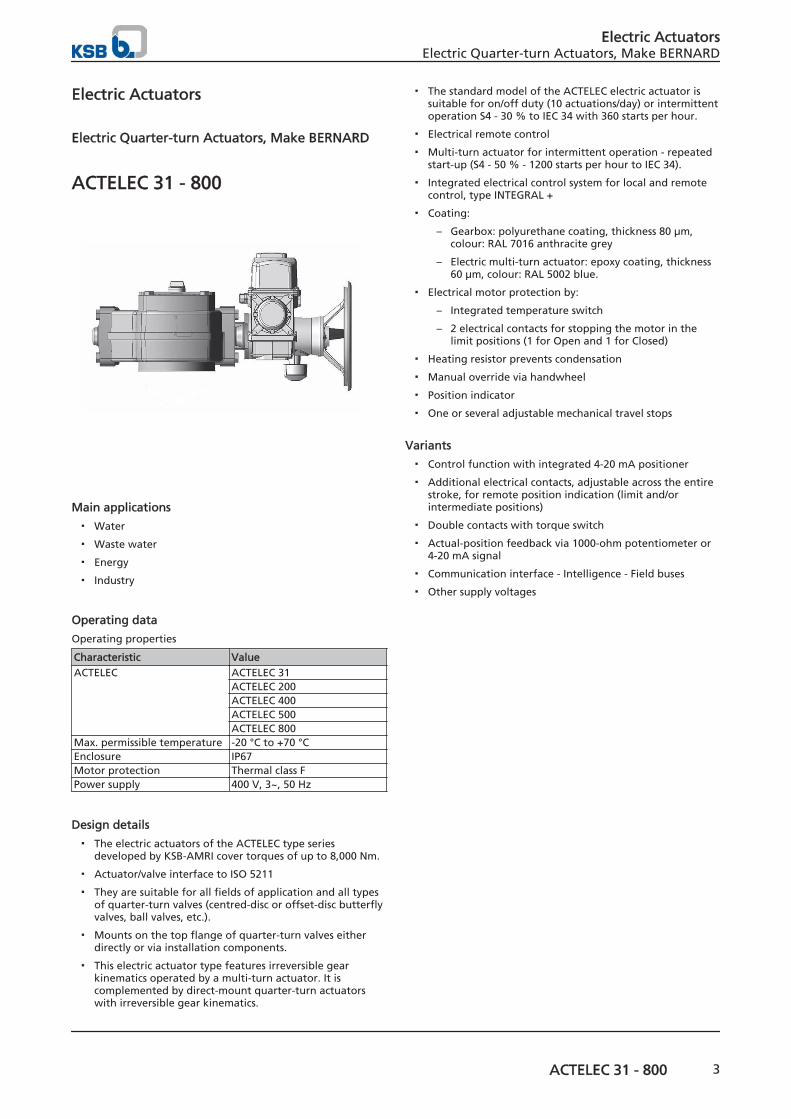
ACTELEC 31 - 800
Main applications
▪ Water
▪ Waste water
▪ Energy
▪ Industry
Operating data
Operating properties
Characteristic ValueACTELEC ACTELEC 31
ACTELEC 200ACTELEC 400ACTELEC 500ACTELEC 800
Max. permissible temperature -20 °C to +70 °CEnclosure IP67Motor protection Thermal class FPower supply 400 V, 3~, 50 Hz
Design details
▪ The electric actuators of the ACTELEC type seriesdeveloped by KSB-AMRI cover torques of up to 8,000 Nm.
▪ Actuator/valve interface to ISO 5211
▪ They are suitable for all fields of application and all typesof quarter-turn valves (centred-disc or offset-disc butterflyvalves, ball valves, etc.).
▪ Mounts on the top flange of quarter-turn valves eitherdirectly or via installation components.
▪ This electric actuator type features irreversible gearkinematics operated by a multi-turn actuator. It iscomplemented by direct-mount quarter-turn actuatorswith irreversible gear kinematics.
▪ The standard model of the ACTELEC electric actuator issuitable for on/off duty (10 actuations/day) or intermittentoperation S4 - 30 % to IEC 34 with 360 starts per hour.
▪ Electrical remote control
▪ Multi-turn actuator for intermittent operation - repeatedstart-up (S4 - 50 % - 1200 starts per hour to IEC 34).
▪ Integrated electrical control system for local and remotecontrol, type INTEGRAL +
▪ Coating:
– Gearbox: polyurethane coating, thickness 80 µm,colour: RAL 7016 anthracite grey
– Electric multi-turn actuator: epoxy coating, thickness60 µm, colour: RAL 5002 blue.
▪ Electrical motor protection by:
– Integrated temperature switch
– 2 electrical contacts for stopping the motor in thelimit positions (1 for Open and 1 for Closed)
▪ Heating resistor prevents condensation
▪ Manual override via handwheel
▪ Position indicator
▪ One or several adjustable mechanical travel stops
Variants
▪ Control function with integrated 4-20 mA positioner
▪ Additional electrical contacts, adjustable across the entirestroke, for remote position indication (limit and/orintermediate positions)
▪ Double contacts with torque switch
▪ Actual-position feedback via 1000-ohm potentiometer or4-20 mA signal
▪ Communication interface - Intelligence - Field buses
▪ Other supply voltages
Electric ActuatorsElectric Quarter-turn Actuators, Make BERNARD
ACTELEC 31 - 800 3
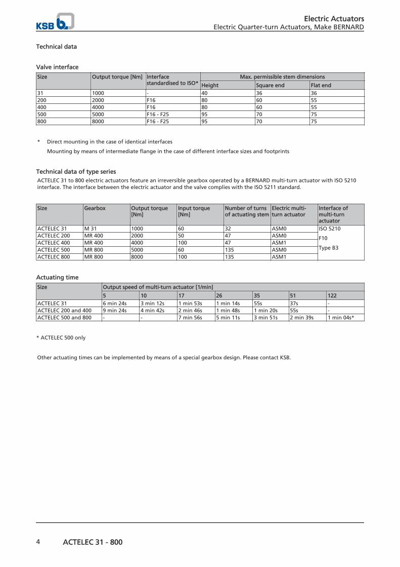
Technical data
Valve interface
Size Output torque [Nm] Interfacestandardised to ISO*
Max. permissible stem dimensions
Height Square end Flat end31 1000 - 40 36 36200 2000 F16 80 60 55400 4000 F16 80 60 55500 5000 F16 - F25 95 70 75800 8000 F16 - F25 95 70 75
* Direct mounting in the case of identical interfaces
Mounting by means of intermediate flange in the case of different interface sizes and footprints
Technical data of type seriesACTELEC 31 to 800 electric actuators feature an irreversible gearbox operated by a BERNARD multi-turn actuator with ISO 5210interface. The interface between the electric actuator and the valve complies with the ISO 5211 standard.
Size Gearbox Output torque[Nm]
Input torque[Nm]
Number of turnsof actuating stem
Electric multi-turn actuator
Interface ofmulti-turnactuator
ACTELEC 31 M 31 1000 60 32 ASM0 ISO 5210
F10
Type B3
ACTELEC 200 MR 400 2000 50 47 ASM0ACTELEC 400 MR 400 4000 100 47 ASM1ACTELEC 500 MR 800 5000 60 135 ASM0ACTELEC 800 MR 800 8000 100 135 ASM1
Actuating time
Size Output speed of multi-turn actuator [1/min]
5 10 17 26 35 51 122ACTELEC 31 6 min 24s 3 min 12s 1 min 53s 1 min 14s 55s 37s -ACTELEC 200 and 400 9 min 24s 4 min 42s 2 min 46s 1 min 48s 1 min 20s 55s -ACTELEC 500 and 800 - - 7 min 56s 5 min 11s 3 min 51s 2 min 39s 1 min 04s*
* ACTELEC 500 only
Other actuating times can be implemented by means of a special gearbox design. Please contact KSB.
Electric ActuatorsElectric Quarter-turn Actuators, Make BERNARD
4 ACTELEC 31 - 800
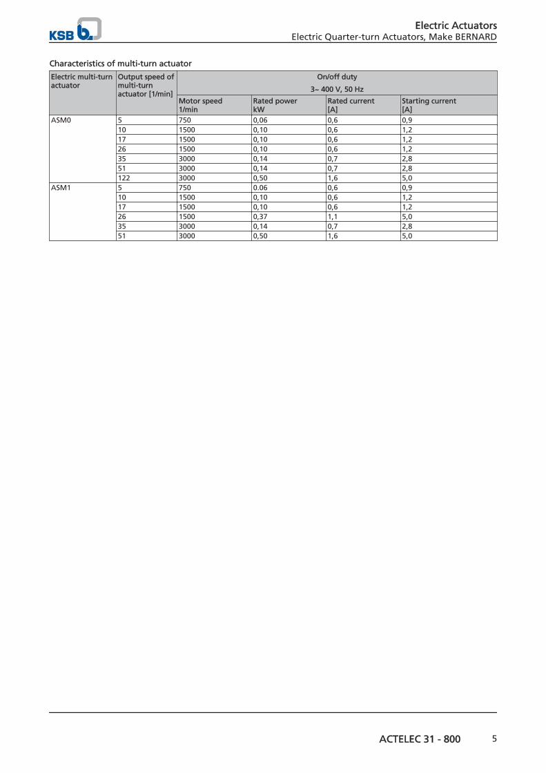
Characteristics of multi-turn actuator
Electric multi-turnactuator
Output speed ofmulti-turnactuator [1/min]
On/off duty
3~ 400 V, 50 Hz
Motor speed 1/min
Rated powerkW
Rated current[A]
Starting current[A]
ASM0 5 750 0,06 0,6 0,910 1500 0,10 0,6 1,217 1500 0,10 0,6 1,226 1500 0,10 0,6 1,235 3000 0,14 0,7 2,851 3000 0,14 0,7 2,8122 3000 0,50 1,6 5,0
ASM1 5 750 0.06 0,6 0,910 1500 0,10 0,6 1,217 1500 0,10 0,6 1,226 1500 0,37 1,1 5,035 3000 0,14 0,7 2,851 3000 0,50 1,6 5,0
Electric ActuatorsElectric Quarter-turn Actuators, Make BERNARD
ACTELEC 31 - 800 5
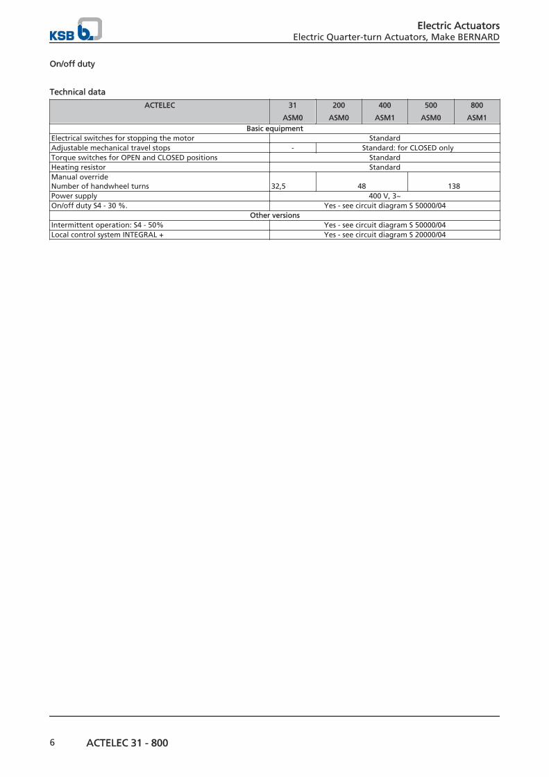
On/off duty
Technical data
ACTELEC 31
ASM0
200
ASM0
400
ASM1
500
ASM0
800
ASM1Basic equipment
Electrical switches for stopping the motor StandardAdjustable mechanical travel stops - Standard: for CLOSED onlyTorque switches for OPEN and CLOSED positions StandardHeating resistor StandardManual overrideNumber of handwheel turns 32,5 48 138Power supply 400 V, 3~On/off duty S4 - 30 %. Yes - see circuit diagram S 50000/04
Other versionsIntermittent operation: S4 - 50% Yes - see circuit diagram S 50000/04Local control system INTEGRAL + Yes - see circuit diagram S 20000/04
Electric ActuatorsElectric Quarter-turn Actuators, Make BERNARD
6 ACTELEC 31 - 800

Circuit diagram S 50000/04
Electric ActuatorsElectric Quarter-turn Actuators, Make BERNARD
ACTELEC 31 - 800 7
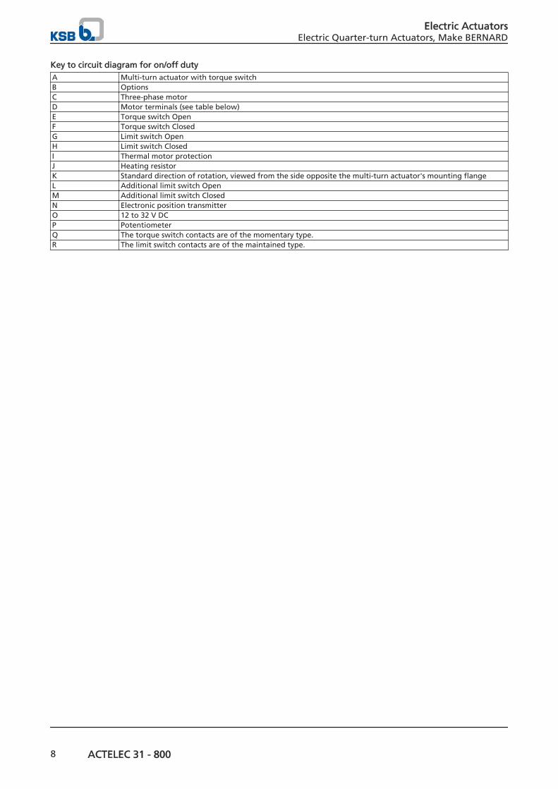
Key to circuit diagram for on/off dutyA Multi-turn actuator with torque switchB OptionsC Three-phase motorD Motor terminals (see table below)E Torque switch OpenF Torque switch ClosedG Limit switch OpenH Limit switch ClosedI Thermal motor protectionJ Heating resistorK Standard direction of rotation, viewed from the side opposite the multi-turn actuator's mounting flangeL Additional limit switch OpenM Additional limit switch ClosedN Electronic position transmitterO 12 to 32 V DCP PotentiometerQ The torque switch contacts are of the momentary type.R The limit switch contacts are of the maintained type.
Electric ActuatorsElectric Quarter-turn Actuators, Make BERNARD
8 ACTELEC 31 - 800

On/off duty: INTEGRAL +
Circuit diagram S 20000/04
Electric ActuatorsElectric Quarter-turn Actuators, Make BERNARD
ACTELEC 31 - 800 9

KeyAA Power supplyA CapacitorB MotorC Thermal motor protectionD Direction 2 ClosingE Limit switchF Direction 1 OpeningG Torque switchH Heating resistorI Common terminal, directions 1 and 2J Control logicK Board C12701L Internal supplyM External supplyN Local controlsO Fault relay, contacts 61 - 63 closed, multi-turn actuator operationalP ~ ACQ 3~ ACR Wiring dependent on voltage of multi-turn actuatorS OptionT Additional limit switch OpenU Additional limit switch ClosedV Actual-position feedback 4 - 20 mAW The 24 V DC power supply at terminals 32-33 can be used.X Potentiometer
The phase sequence is irrelevant. If a phase is missing, the multi-turn actuator will not start and a fault message will be output(fault relay).
Assignment of messages see configuration data sheet
Contact Code Description Code DescriptionR1 14 LSO Limit switch Open TSO Torque switch OpenR2 15 LSC Limit switch Closed TSC Torque switch ClosedR3 16 LSO
17 Local
18 Running
Limit switch Open
Selector switch set to Local
Actuator is running
TSO
Remote
Opening
Torque switch Open
Selector switch set to remotecontrol
Actuator is openingR4 19 LSC
20 ESD
21 Local
Limit switch Closed
Emergency shutdown
Selector switch set to Local
TSC
Closing
Remote
Torque switch Closed
Actuator is closing
Selector switch set to remotecontrol
Each contact can be configured to be normally open (NO = standard) or normally closed (NC). Only one setting can be selectedper message. In the de-energised state, contacts are always open.
Configuration 7A 7BDirection 1 Opening ClosingDirection 2 Closing Opening
Electric ActuatorsElectric Quarter-turn Actuators, Make BERNARD
10 ACTELEC 31 - 800
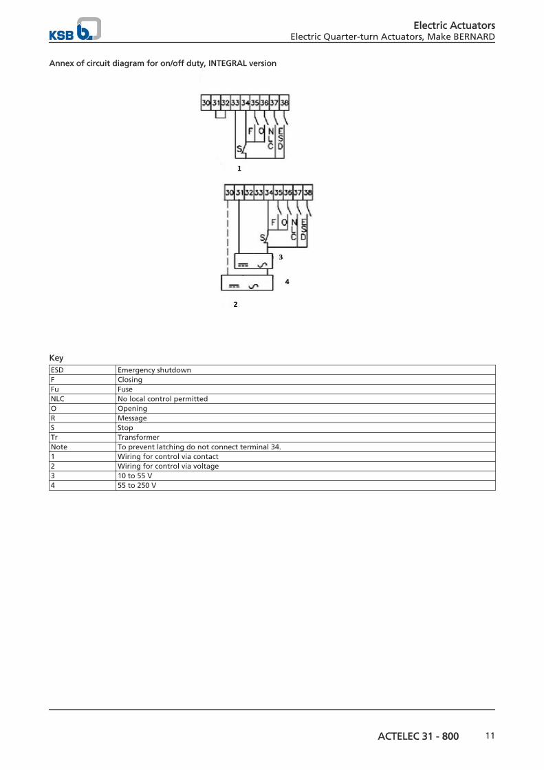
Annex of circuit diagram for on/off duty, INTEGRAL version
KeyESD Emergency shutdownF ClosingFu FuseNLC No local control permittedO OpeningR MessageS StopTr TransformerNote To prevent latching do not connect terminal 34.1 Wiring for control via contact2 Wiring for control via voltage3 10 to 55 V4 55 to 250 V
Electric ActuatorsElectric Quarter-turn Actuators, Make BERNARD
ACTELEC 31 - 800 11
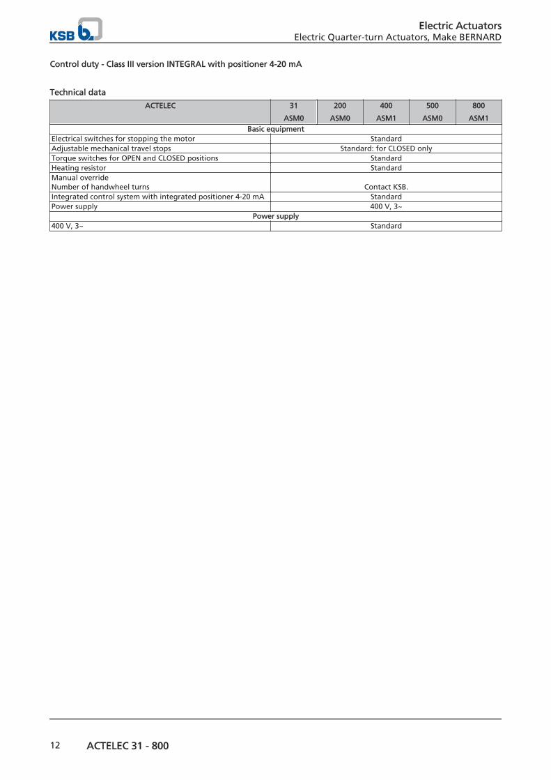
Control duty - Class III version INTEGRAL with positioner 4-20 mA
Technical data
ACTELEC 31
ASM0
200
ASM0
400
ASM1
500
ASM0
800
ASM1Basic equipment
Electrical switches for stopping the motor StandardAdjustable mechanical travel stops Standard: for CLOSED onlyTorque switches for OPEN and CLOSED positions StandardHeating resistor StandardManual overrideNumber of handwheel turns Contact KSB.Integrated control system with integrated positioner 4-20 mA StandardPower supply 400 V, 3~
Power supply400 V, 3~ Standard
Electric ActuatorsElectric Quarter-turn Actuators, Make BERNARD
12 ACTELEC 31 - 800
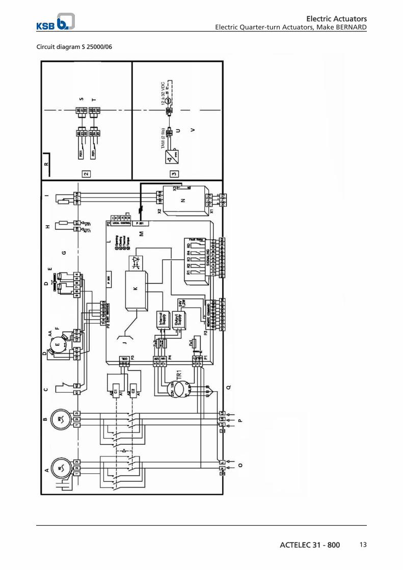
Circuit diagram S 25000/06
Electric ActuatorsElectric Quarter-turn Actuators, Make BERNARD
ACTELEC 31 - 800 13
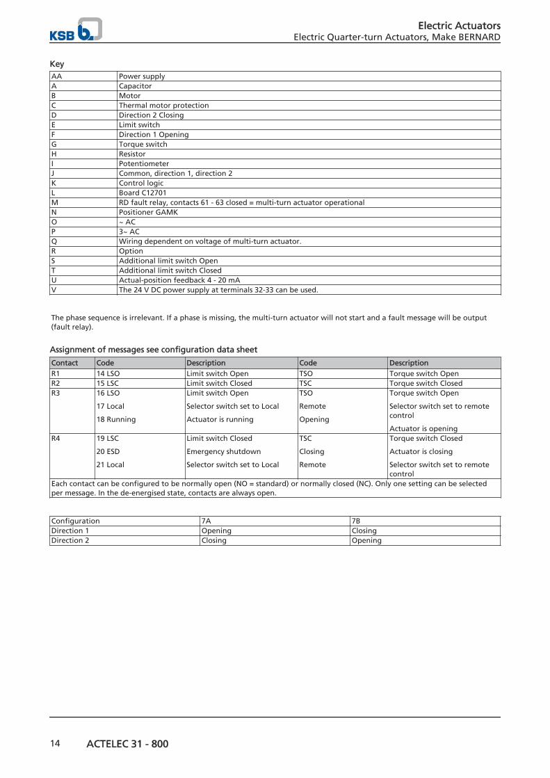
KeyAA Power supplyA CapacitorB MotorC Thermal motor protectionD Direction 2 ClosingE Limit switchF Direction 1 OpeningG Torque switchH ResistorI PotentiometerJ Common, direction 1, direction 2K Control logicL Board C12701M RD fault relay, contacts 61 - 63 closed = multi-turn actuator operationalN Positioner GAMKO ~ ACP 3~ ACQ Wiring dependent on voltage of multi-turn actuator.R OptionS Additional limit switch OpenT Additional limit switch ClosedU Actual-position feedback 4 - 20 mAV The 24 V DC power supply at terminals 32-33 can be used.
The phase sequence is irrelevant. If a phase is missing, the multi-turn actuator will not start and a fault message will be output(fault relay).
Assignment of messages see configuration data sheet
Contact Code Description Code DescriptionR1 14 LSO Limit switch Open TSO Torque switch OpenR2 15 LSC Limit switch Closed TSC Torque switch ClosedR3 16 LSO
17 Local
18 Running
Limit switch Open
Selector switch set to Local
Actuator is running
TSO
Remote
Opening
Torque switch Open
Selector switch set to remotecontrol
Actuator is openingR4 19 LSC
20 ESD
21 Local
Limit switch Closed
Emergency shutdown
Selector switch set to Local
TSC
Closing
Remote
Torque switch Closed
Actuator is closing
Selector switch set to remotecontrol
Each contact can be configured to be normally open (NO = standard) or normally closed (NC). Only one setting can be selectedper message. In the de-energised state, contacts are always open.
Configuration 7A 7BDirection 1 Opening ClosingDirection 2 Closing Opening
Electric ActuatorsElectric Quarter-turn Actuators, Make BERNARD
14 ACTELEC 31 - 800
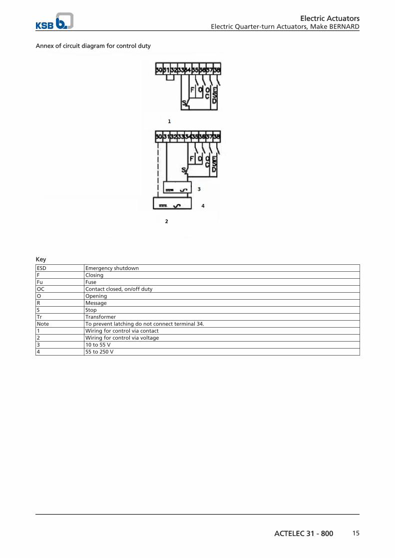
Annex of circuit diagram for control duty
KeyESD Emergency shutdownF ClosingFu FuseOC Contact closed, on/off dutyO OpeningR MessageS StopTr TransformerNote To prevent latching do not connect terminal 34.1 Wiring for control via contact2 Wiring for control via voltage3 10 to 55 V4 55 to 250 V
Electric ActuatorsElectric Quarter-turn Actuators, Make BERNARD
ACTELEC 31 - 800 15
Materials
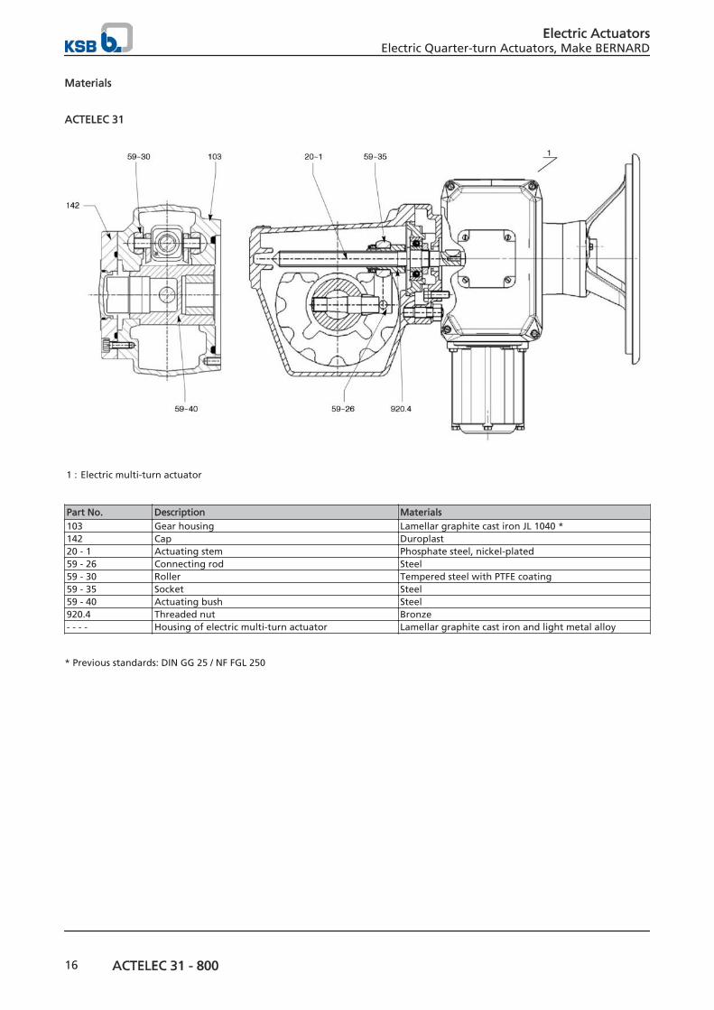
ACTELEC 31
1 : Electric multi-turn actuator
Part No. Description Materials103 Gear housing Lamellar graphite cast iron JL 1040 *142 Cap Duroplast20 - 1 Actuating stem Phosphate steel, nickel-plated59 - 26 Connecting rod Steel59 - 30 Roller Tempered steel with PTFE coating59 - 35 Socket Steel59 - 40 Actuating bush Steel920.4 Threaded nut Bronze- - - - Housing of electric multi-turn actuator Lamellar graphite cast iron and light metal alloy
* Previous standards: DIN GG 25 / NF FGL 250
Electric ActuatorsElectric Quarter-turn Actuators, Make BERNARD
16 ACTELEC 31 - 800
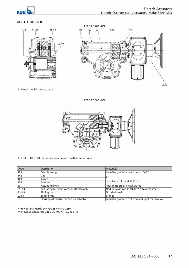
ACTELEC 200 - 800ACTELEC 200 - 800
1 - Electric multi-turn actuator
ACTELEC 500 - 800
ACTELEC 500 to 800 actuators are equipped with input reducers.
Code Description Materials103 Gear housing Lamellar graphite cast iron JL 1040 *
or
nodular cast iron JS 1030 **
142 Cap160 Cover176 Bottom20- 1 Actuating stem Phosphate steel, nickel-plated59- 40 Actuating bush/indicator shaft assembly Nodular cast iron JS 1030 ** / stainless steel81- 68 Sliding pad Nitrided steel920.1 Sliding nut Bronze---- Housing of electric multi-turn actuator Lamellar graphite cast iron and light metal alloy
* Previous standards: DIN GG 25 / NF FGL 250** Previous standards: DIN GGG 40 / NF FGS 400- 15
Electric ActuatorsElectric Quarter-turn Actuators, Make BERNARD
ACTELEC 31 - 800 17

Dimensions
DrawingsACTELEC 31
ACTELEC 200 and 400
ACTELEC 500 and 800
1 : 2 cable glands No. 20 2 : Bore diameter ød1 3 : n evenly spaced holes ød2
Electric ActuatorsElectric Quarter-turn Actuators, Make BERNARD
18 ACTELEC 31 - 800
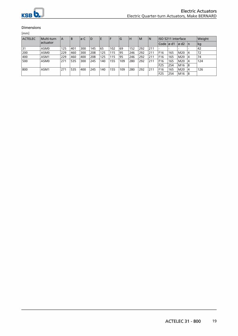
Dimensions
[mm]
ACTELEC Multi-turnactuator
A B ø C D E F G H M N ISO 5211 interface Weight
Code ø d1 ø d2 n kg31 ASM0 125 401 300 145 65 102 69 152 292 211 - - - - 42200 ASM0 229 460 300 208 125 115 95 246 292 211 F16 165 M20 4 72400 ASM1 229 460 400 208 125 115 95 246 292 211 F16 165 M20 4 74500 ASM0 271 535 300 245 140 155 109 280 292 211 F16 165 M20 4 124
F25 254 M16 8800 ASM1 271 535 400 245 140 155 109 280 292 211 F16 165 M20 4 126
F25 254 M16 8
Electric ActuatorsElectric Quarter-turn Actuators, Make BERNARD
ACTELEC 31 - 800 19
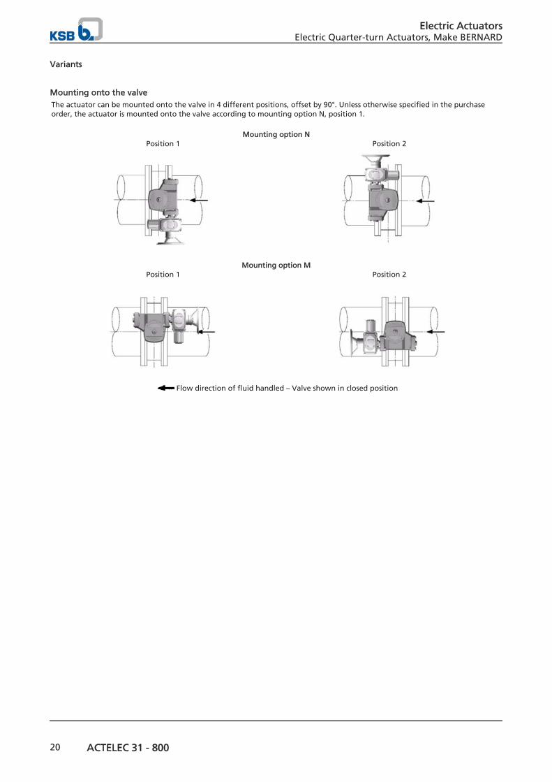
Variants
Mounting onto the valveThe actuator can be mounted onto the valve in 4 different positions, offset by 90°. Unless otherwise specified in the purchaseorder, the actuator is mounted onto the valve according to mounting option N, position 1.
Mounting option NPosition 1 Position 2
Mounting option M
Position 1 Position 2
Flow direction of fluid handled – Valve shown in closed position
Electric ActuatorsElectric Quarter-turn Actuators, Make BERNARD
20 ACTELEC 31 - 800


8521
.15/
3-EN
15.0
6.20
15
KSB S.A.S.4, allée des Barbanniers • 92635 Gennevilliers Cedex (France)Tél. +33 1 41 47 75 00 • Fax +33 1 41 47 75 10 • www.ksb.com