mycommittees.api.orgmycommittees.api.org/standards/ecs/sc6/10423 activities... · web viewa basic...
TRANSCRIPT
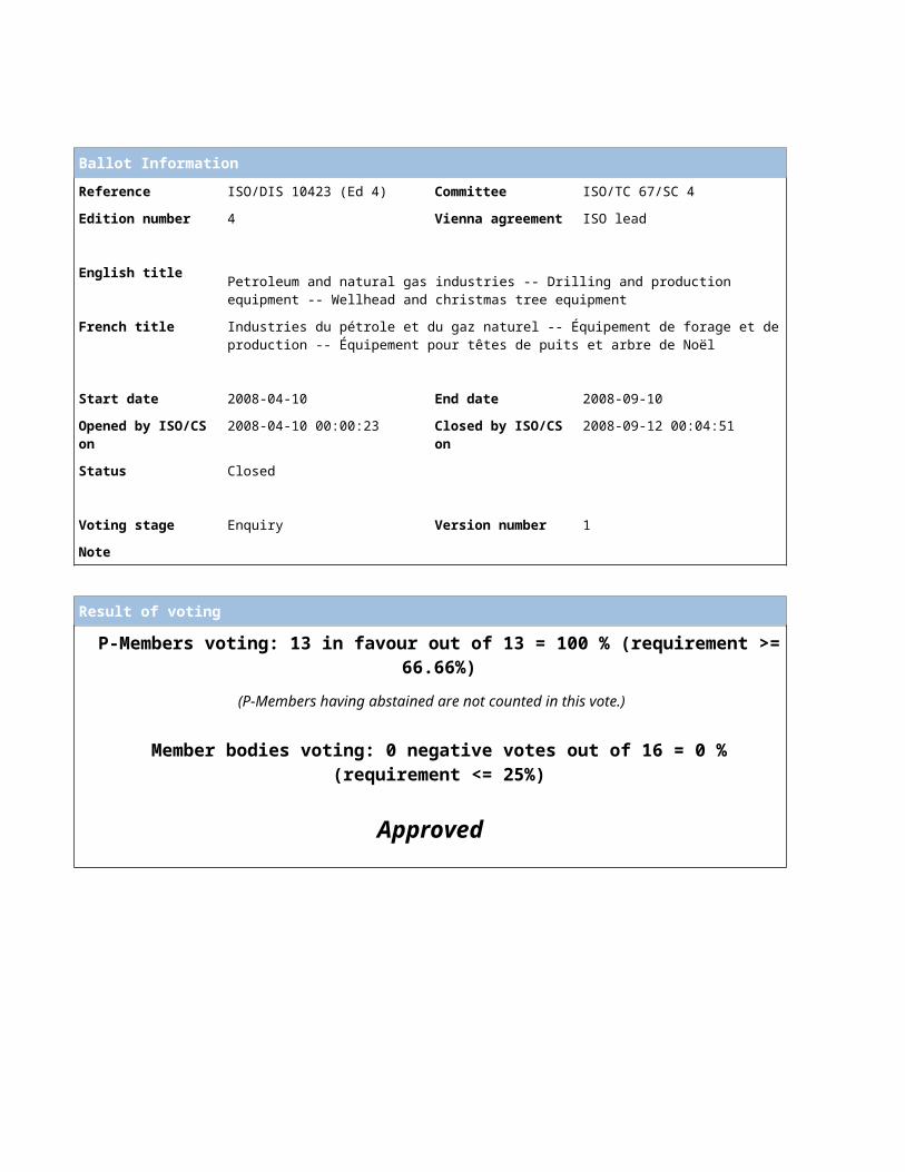
Ballot Information
Reference ISO/DIS 10423 (Ed 4) Committee ISO/TC 67/SC 4
Edition number 4 Vienna agreement ISO lead
English titlePetroleum and natural gas industries -- Drilling and production equipment -- Wellhead and christmas tree equipment
French title Industries du pétrole et du gaz naturel -- Équipement de forage et de production -- Équipement pour têtes de puits et arbre de Noël
Start date 2008-04-10 End date 2008-09-10
Opened by ISO/CS on 2008-04-10 00:00:23 Closed by ISO/CS on 2008-09-12 00:04:51
Status Closed
Voting stage Enquiry Version number 1
Note
Result of voting
P-Members voting: 13 in favour out of 13 = 100 % (requirement >= 66.66%)
(P-Members having abstained are not counted in this vote.)
Member bodies voting: 0 negative votes out of 16 = 0 % (requirement <= 25%)
Approved
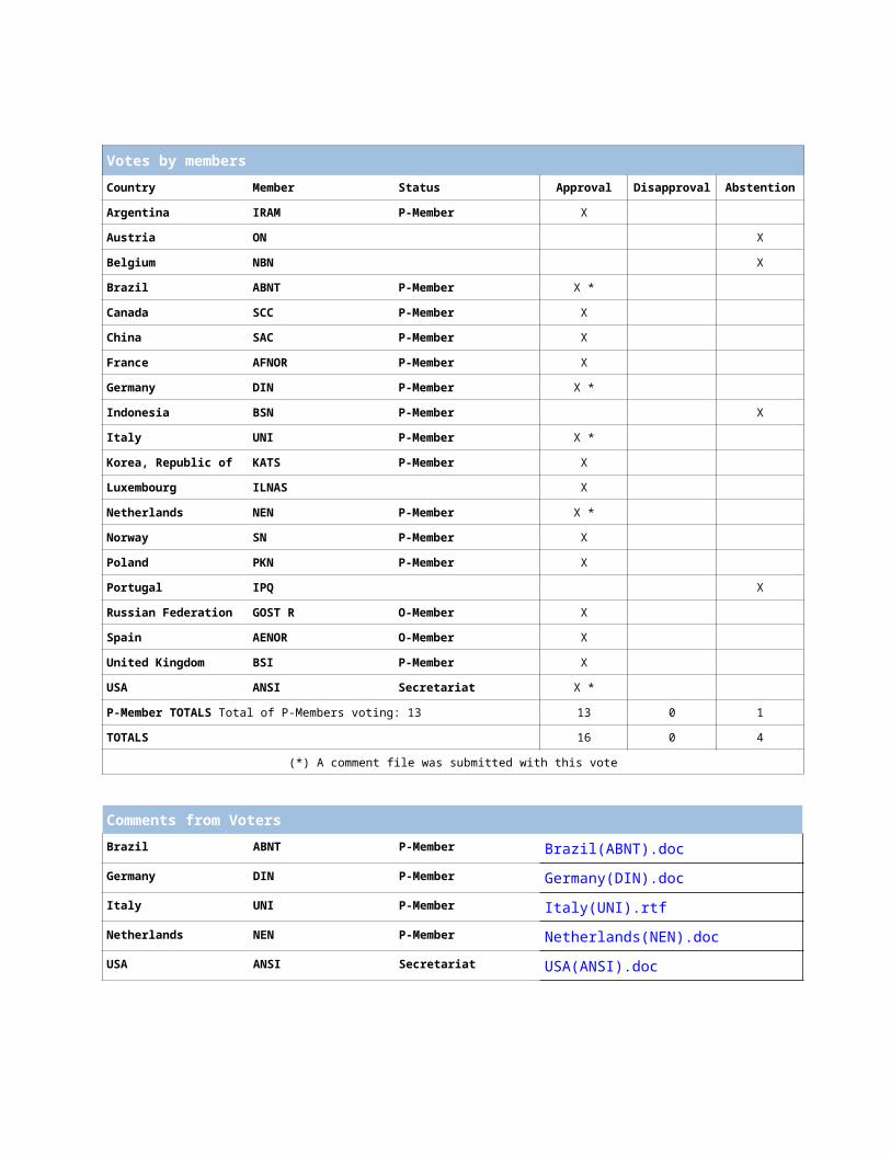
Votes by membersCountry Member Status Approval Disapproval Abstention
Argentina IRAM P-Member X
Austria ON X
Belgium NBN X
Brazil ABNT P-Member X *
Canada SCC P-Member X
China SAC P-Member X
France AFNOR P-Member X
Germany DIN P-Member X *
Indonesia BSN P-Member X
Italy UNI P-Member X *
Korea, Republic of KATS P-Member X
Luxembourg ILNAS X
Netherlands NEN P-Member X *
Norway SN P-Member X
Poland PKN P-Member X
Portugal IPQ X
Russian Federation GOST R O-Member X
Spain AENOR O-Member X
United Kingdom BSI P-Member X
USA ANSI Secretariat X *
P-Member TOTALS Total of P-Members voting: 13 13 0 1
TOTALS 16 0 4
(*) A comment file was submitted with this vote
Comments from VotersBrazil ABNT P-Member Brazil(ABNT).doc
Germany DIN P-Member Germany(DIN).doc
Italy UNI P-Member Italy(UNI).rtf
Netherlands NEN P-Member Netherlands(NEN).doc
USA ANSI Secretariat USA(ANSI).doc
Comments from CommentersISO ISO.doc
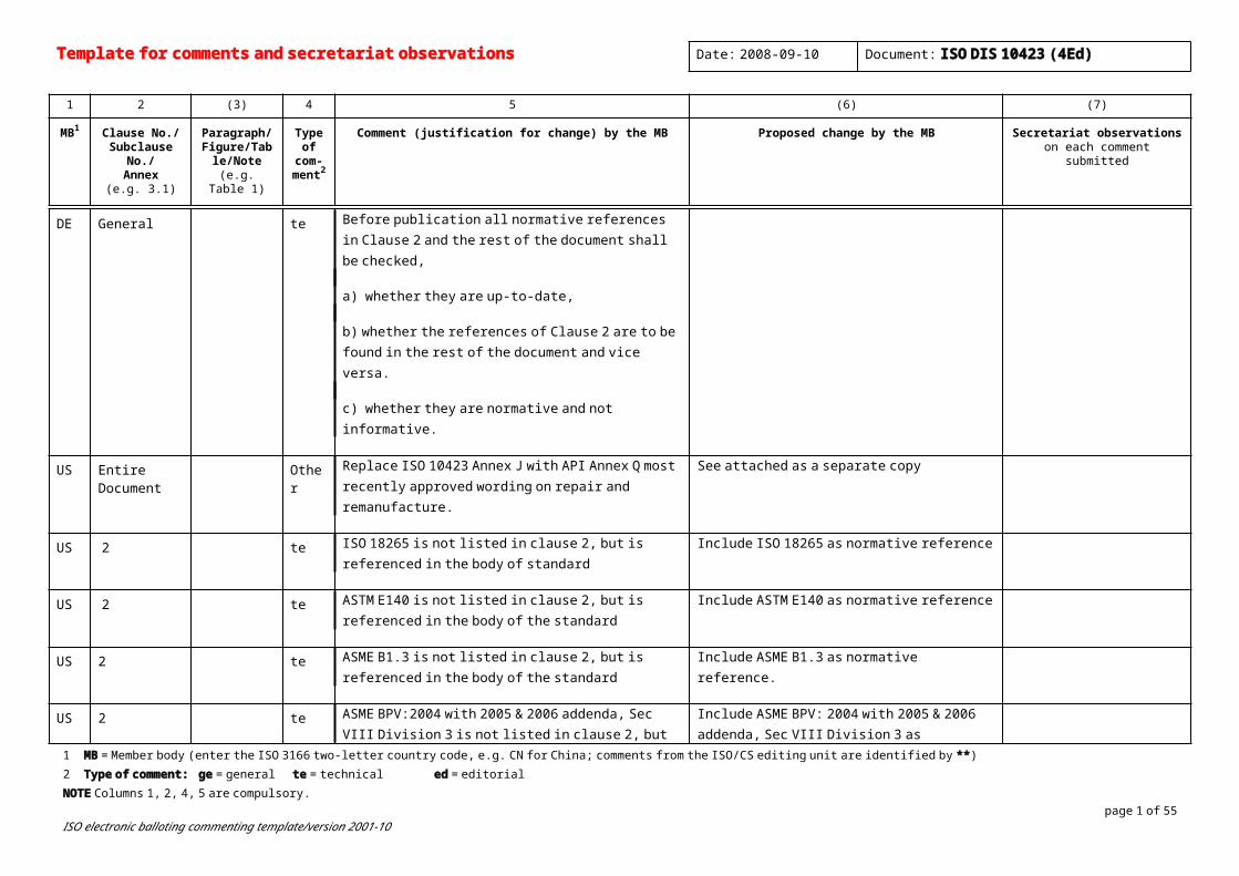
Template for comments and secretariat observations Date: 2008-09-10 Document: ISO DIS 10423 (4Ed)
1 2 (3) 4 5 (6) (7)
MB1 Clause No./Subclause No./
Annex(e.g. 3.1)
Paragraph/Figure/Table/N
ote(e.g. Table 1)
Type of com-
ment2
Comment (justification for change) by the MB Proposed change by the MB Secretariat observationson each comment submitted
DE General te Before publication all normative references in Clause 2 and the rest of the document shall be checked,
a) whether they are up-to-date,
b) whether the references of Clause 2 are to be found in the rest of the document and vice versa.
c) whether they are normative and not informative.
US Entire Document
Other Replace ISO 10423 Annex J with API Annex Q most recently approved wording on repair and remanufacture.
See attached as a separate copy
US 2 te ISO 18265 is not listed in clause 2, but is referenced in the body of standard
Include ISO 18265 as normative reference
US 2 te ASTM E140 is not listed in clause 2, but is referenced in the body of the standard
Include ASTM E140 as normative reference
US 2 te ASME B1.3 is not listed in clause 2, but is referenced in the body of the standard
Include ASME B1.3 as normative reference.
US 2 te ASME BPV:2004 with 2005 & 2006 addenda, Sec VIII Division 3 is not listed in clause 2, but is referenced in the body of the standard
Include ASME BPV: 2004 with 2005 & 2006 addenda, Sec VIII Division 3 as normative reference.
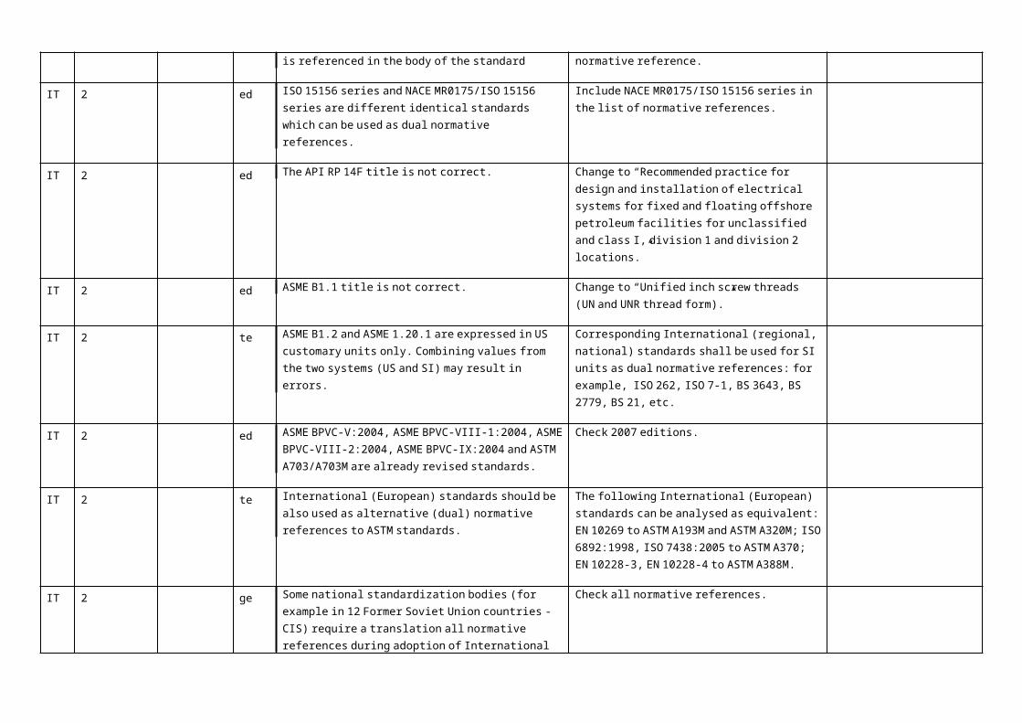
IT 2 ed ISO 15156 series and NACE MR0175/ISO 15156 series are different identical standards which can be used as dual normative references.
Include NACE MR0175/ISO 15156 series in the list of normative references.
IT 2 ed The API RP 14F title is not correct. Change to “Recommended practice for design and installation of electrical systems for fixed and floating offshore petroleum facilities for
1 MB = Member body (enter the ISO 3166 two-letter country code, e.g. CN for China; comments from the ISO/CS editing unit are identified by **)2 Type of comment: ge = general te = technical ed = editorial NOTE Columns 1, 2, 4, 5 are compulsory.
page 1 of 40ISO electronic balloting commenting template/version 2001-10
unclassified and class I, division 1 and division 2 locations.”
IT 2 ed ASME B1.1 title is not correct. Change to “Unified inch screw threads (UN and UNR thread form).”
IT 2 te ASME B1.2 and ASME 1.20.1 are expressed in US customary units only. Combining values from the two systems (US and SI) may result in errors.
Corresponding International (regional, national) standards shall be used for SI units as dual normative references: for example, ISO 262, ISO 7-1, BS 3643, BS 2779, BS 21, etc.
IT 2 ed ASME BPVC-V:2004, ASME BPVC-VIII-1:2004, ASME BPVC-VIII-2:2004, ASME BPVC-IX:2004 and ASTM A703/A703M are already revised standards.
Check 2007 editions.
IT 2 te International (European) standards should be also used as alternative (dual) normative references to ASTM standards.
The following International (European) standards can be analysed as equivalent: EN 10269 to ASTM A193M and ASTM A320M; ISO 6892:1998, ISO 7438:2005 to ASTM A370; EN 10228-3, EN 10228-4 to ASTM A388M.
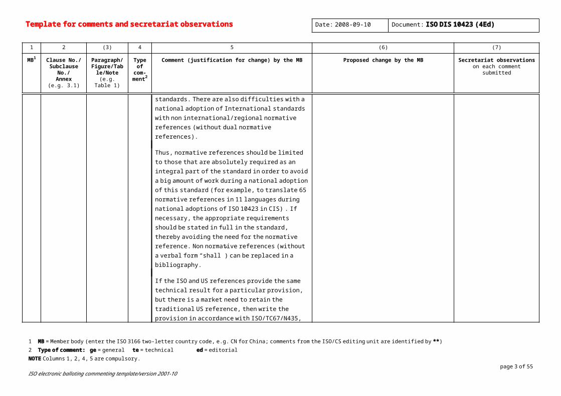
IT 2 ge Some national standardization bodies (for example in 12 Former Soviet Union countries - CIS) require a translation all normative references during adoption of International standards. There are also difficulties with a national adoption of International standards with non international/regional normative references (without dual normative references).
Thus, normative references should be limited to those that are absolutely required as an integral part of the standard in order to avoid a big amount of work during a national adoption of this standard (for example, to translate 65 normative references in 11 languages during national adoptions of ISO 10423 in CIS) . If necessary, the appropriate requirements should be stated in full in the standard, thereby avoiding the need for the normative reference. Non normative references (without a verbal form “shall”) can be replaced in a bibliography.
If the ISO and US references provide the same technical result for a particular provision, but there is a market need to retain the traditional US reference, then write the
Check all normative references.
Template for comments and secretariat observations Date: 2008-09-10 Document: ISO DIS 10423 (4Ed)
1 2 (3) 4 5 (6) (7)
MB1 Clause No./Subclause No./
Annex(e.g. 3.1)
Paragraph/Figure/Table/N
ote(e.g. Table 1)
Type of com-
ment2
Comment (justification for change) by the MB Proposed change by the MB Secretariat observationson each comment submitted
provision in accordance with ISO/TC67/N435, Annex I. See also ISO 11960 as an example.
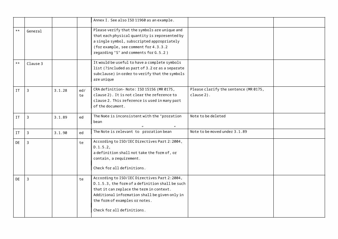
** General Please verify that the symbols are unique and that each physical quantity is represented by a single symbol, subscripted appropriately (for example, see comment for 4.3.3.2 regarding "S" and comments for G.5.2 )
** Clause 3 It would be useful to have a complete symbols list (?included as part of 3.2 or as a separate subclause) in order to verify that the symbols are unique
IT 3 3.1.28 ed/te CRA definition- Note: ISO 15156 (MR 0175, clause 2). It is not clear the reference to clause 2. This reference is used in many part of the document.
Please clarify the sentence (MR 0175, clause 2).
IT 3 3.1.89 ed The Note is inconsistent with the “proration bean” Note to be deleted
IT 3 3.1.90 ed The Note is relevant to” proration bean” Note to be moved under 3.1.89
DE 3 te According to ISO/IEC Directives Part 2:2004, D.1.5.2, a definition shall not take the form of, or contain, a requirement.
Check for all definitions.
DE 3 te According to ISO/IEC Directives Part 2:2004, D.1.5.3, the form of a definition shall be such that it can replace the term in context. Additional information shall be given only in the form of examples or notes.
Check for all definitions.
1 MB = Member body (enter the ISO 3166 two-letter country code, e.g. CN for China; comments from the ISO/CS editing unit are identified by **)2 Type of comment: ge = general te = technical ed = editorial NOTE Columns 1, 2, 4, 5 are compulsory.
page 3 of 40ISO electronic balloting commenting template/version 2001-10
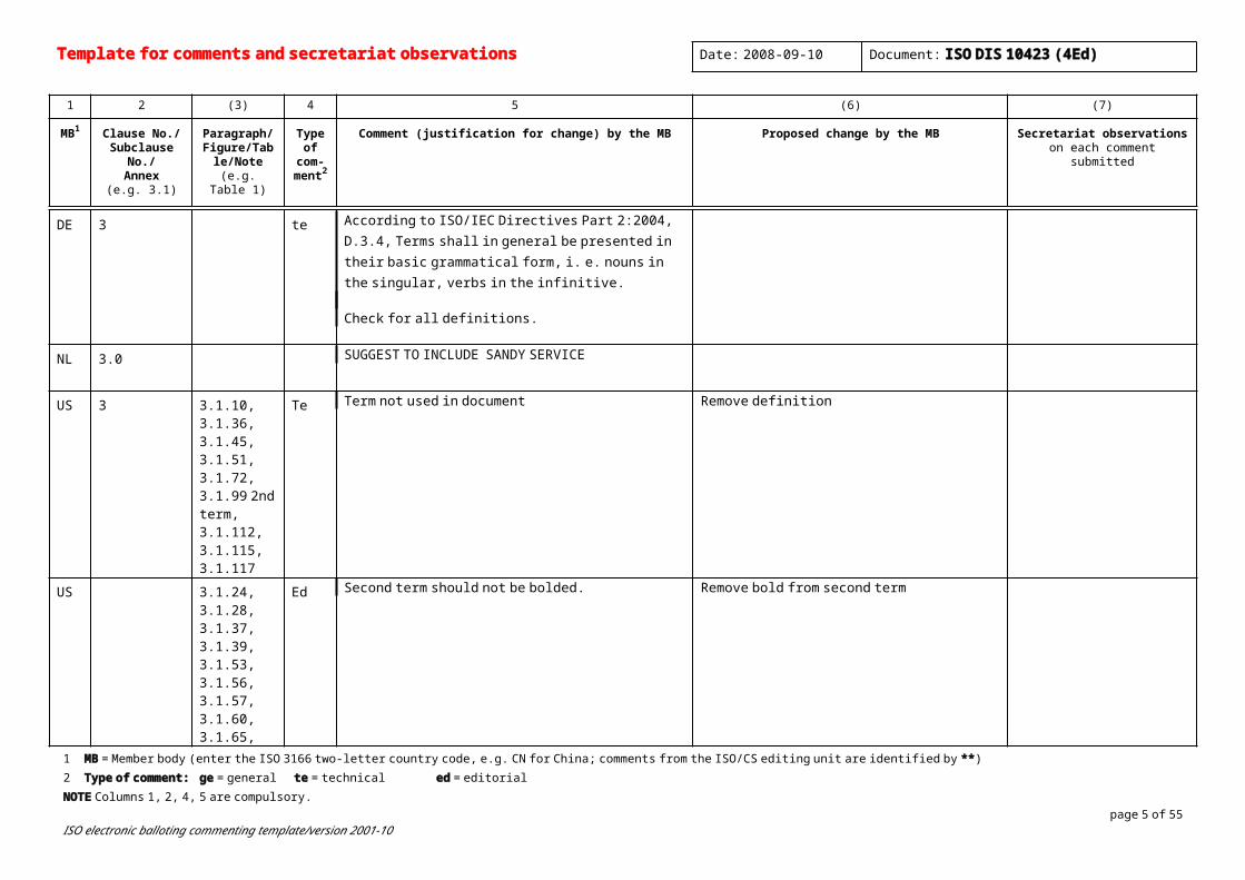
DE 3 te According to ISO/IEC Directives Part 2:2004, D.3.4, Terms shall in general be presented in their basic grammatical form, i. e. nouns in the singular, verbs in the infinitive.
Check for all definitions.
NL 3.0 SUGGEST TO INCLUDE SANDY SERVICE
US 3 3.1.10, 3.1.36, 3.1.45, 3.1.51, 3.1.72, 3.1.99 2nd term, 3.1.112, 3.1.115, 3.1.117
Te Term not used in document Remove definition
US 3.1.24, 3.1.28, 3.1.37, 3.1.39, 3.1.53, 3.1.56, 3.1.57, 3.1.60, 3.1.65, 3.1.99, 3.1.109, 3.1.118, 3.1.119, 3.1.125, 3.1.130, 3.1.135
Ed Second term should not be bolded. Remove bold from second term
US 3.1.79 Ed Extraneous text Remove strikethrough text
US 3.1.89 Ed Incorrect NOTE Remove exisiting NOTE and replace with NOTE from 3.1.90 below it to read:
NOTE: proration is a system of allocating the amount of oil or gas a well or field is allowed to produce within a given period by a regulatory agency.
Template for comments and secretariat observations Date: 2008-09-10 Document: ISO DIS 10423 (4Ed)
1 2 (3) 4 5 (6) (7)
MB1 Clause No./Subclause No./
Annex(e.g. 3.1)
Paragraph/Figure/Table/N
ote(e.g. Table 1)
Type of com-
ment2
Comment (justification for change) by the MB Proposed change by the MB Secretariat observationson each comment submitted
US 3.1.90 Ed Extraneous text Remove NOTE.
US 3.1.108 Ed The term "specified material" is not used in the document by itself. Everywhere in the document, it is called manufacturer-specified material.
Change the term to be "manufacturer-specified material" with the same definition.
US 3.1.56 Ed alternating steps of controlled heating and cooling of materials for the purpose of changing physical or mechanical properties
The word “alternating” implies going back and forth between two states.
A specified, timed sequence of heating and cooling…
US 3.1.26 hub Ed protruding rim with an external angled shoulder and a sealing mechanism used to join pressure-containing equipment
Reason: the term “hub” is also used to describe that portion of a flange that extends from the back face of the flange. It is specified for the 6B flanges with the X dimension and for the 6BX flanges with the J1, J2, and J3 dimensions. Tables 36 – 47 abound with the term “hub.” Let’s be more specific with clamp hubs, that’s what they have always been called.
3.1.62 clamp hub protruding rim with an external angled shoulder and a sealing mechanism used to join pressure-containing equipment
1 MB = Member body (enter the ISO 3166 two-letter country code, e.g. CN for China; comments from the ISO/CS editing unit are identified by **)2 Type of comment: ge = general te = technical ed = editorial NOTE Columns 1, 2, 4, 5 are compulsory.
page 5 of 40ISO electronic balloting commenting template/version 2001-10
US 3.1.71 Master valve
Ed lowermost valve on the vertical bore of the christmas tree
NOTE It is used to completely shut in the well.
Reason: The previous definition ignores the existence of the upper master valve which is the SSV on offshore wells. The note implies that the master valve should be used to shut in a well. However the proper practice is to close first the wing valve, then the upper master, and finally the lower master. The objective is to preserve the integrity of the lower master which is part of the primary containment.
Any valve below the wing of a christmas tree in the vertical run.
NOTE:The lower master valve is the last valve closed to completely shut in a well.
Bean Steels?
Remove the note from 3.1.89. Substitute the note from 3.1.90.
US 3.1.93 Relevant indication
Ed The examples are examples of non-relevant indications This should be clarified by removing the “EXAMPLES” heading and saying “for example” on the end of the previous sentence which describes non-relevant indications.
US 3.1.95 Ed Replace “heat reating” with “heat treating.”
US 3.1.137 weld groove
Ed area between two metals to be joined that has been prepared to receive weld-filler metal
Reason: It’s two parts, not necessarily two different metals.
The shape of the mating ends of two parts to be joined by welding
US 3.1.138 weld Ed fitting together of components in order to facilitate joining A system comprising two or more parts prepared

Template for comments and secretariat observations Date: 2008-09-10 Document: ISO DIS 10423 (4Ed)
1 2 (3) 4 5 (6) (7)
MB1 Clause No./Subclause No./
Annex(e.g. 3.1)
Paragraph/Figure/Table/N
ote(e.g. Table 1)
Type of com-
ment2
Comment (justification for change) by the MB Proposed change by the MB Secretariat observationson each comment submitted
joint by welding
Reason: the present definition is incorrect. A weld joint isn’t the act of fitting anything.
for welding and the actual weld or welds joining the parts.
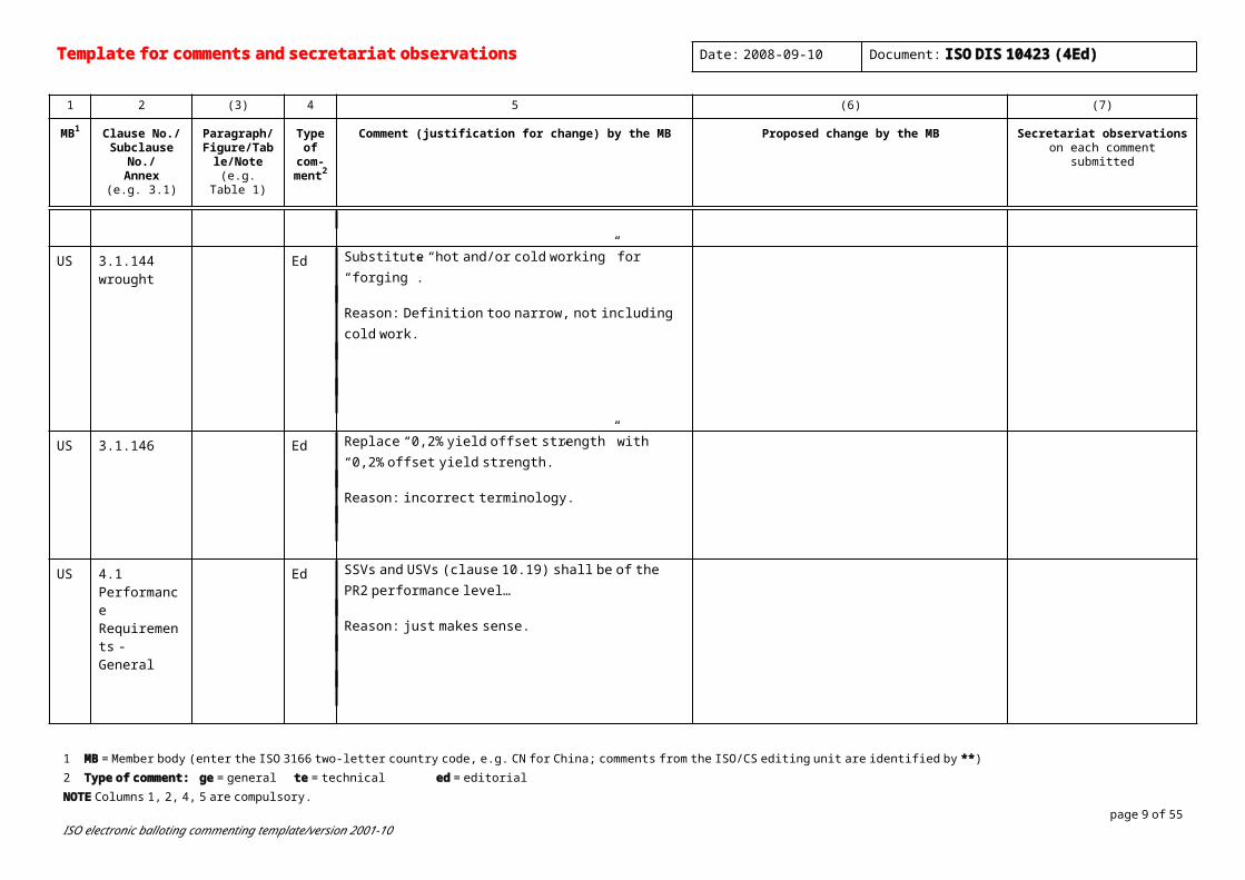
US 3.1.144 wrought
Ed Substitute “hot and/or cold working” for “forging”.
Reason: Definition too narrow, not including cold work.
US 3.1.146 Ed Replace “0,2% yield offset strength” with “0,2% offset yield strength.”
Reason: incorrect terminology.
US 4.1 Performance Requirements - General
Ed SSVs and USVs (clause 10.19) shall be of the PR2 performance level…
Reason: just makes sense.
1 MB = Member body (enter the ISO 3166 two-letter country code, e.g. CN for China; comments from the ISO/CS editing unit are identified by **)2 Type of comment: ge = general te = technical ed = editorial NOTE Columns 1, 2, 4, 5 are compulsory.
page 7 of 40ISO electronic balloting commenting template/version 2001-10

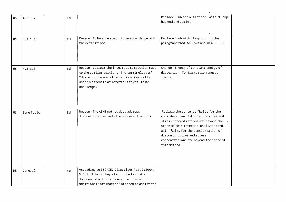
US 4.3.1.2 Ed Replace “Hub and outlet end” with “Clamp hub end and outlet”
US 4.3.1.3 Ed Reason: To be more specific in accordance with the definitions.
Replace “hub with clamp hub” in the paragraph that follows and in 4.3.1.3
US 4.3.3.3 Ed Reason: correct the incorrect correction made to the earlier editions. The terminology of “distortion energy theory” is universally used in strength of materials texts, to my knowledge.
Change “Theory of constant energy of distortion” To “Distortion energy theory.”
US Same Topic Ed Reason: The ASME method does address discontinuities and stress concentrations.
Replace the sentence “Rules for the consideration of discontinuities and stress concentrations are beyond the scope of this International Standard.” with “Rules for the consideration of discontinuities and stress concentrations are beyond the scope of this method.”
DE General te According to ISO/IEC Directives Part 2:2004, 6.5.1, Notes integrated in the text of a document shall only be used for giving additional information intended to assist the understanding or use of the document. These elements shall not contain requirements or any information considered indispensable for the use of the document.
Check for all notes.
DE General te According to ISO/IEC Directives Part 2:2004, 6.4.1.1, Informative annexes give additional information intended to assist the understanding or use of the document. They

Template for comments and secretariat observations Date: 2008-09-10 Document: ISO DIS 10423 (4Ed)
1 2 (3) 4 5 (6) (7)
MB1 Clause No./Subclause No./
Annex(e.g. 3.1)
Paragraph/Figure/Table/N
ote(e.g. Table 1)
Type of com-
ment2
Comment (justification for change) by the MB Proposed change by the MB Secretariat observationson each comment submitted
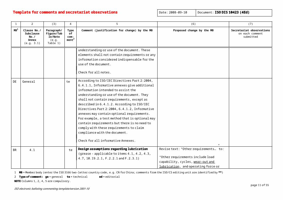
shall not contain requirements, except as described in 6.4.1.2. According to ISO/IEC Directives Part 2:2004, 6.4.1.2, Informative annexes may contain optional requirements. For example, a test method that is optional may contain requirements but there is no need to comply with these requirements to claim compliance with the document.
Check for all informative Annexes.
BR 4.1 te Design assumptions regarding lubrication (grease - applicable to items 4.1, 4.2, 4.3, 4.7, 10.19.2.1, F.2.2.1 and F.2.3.1)
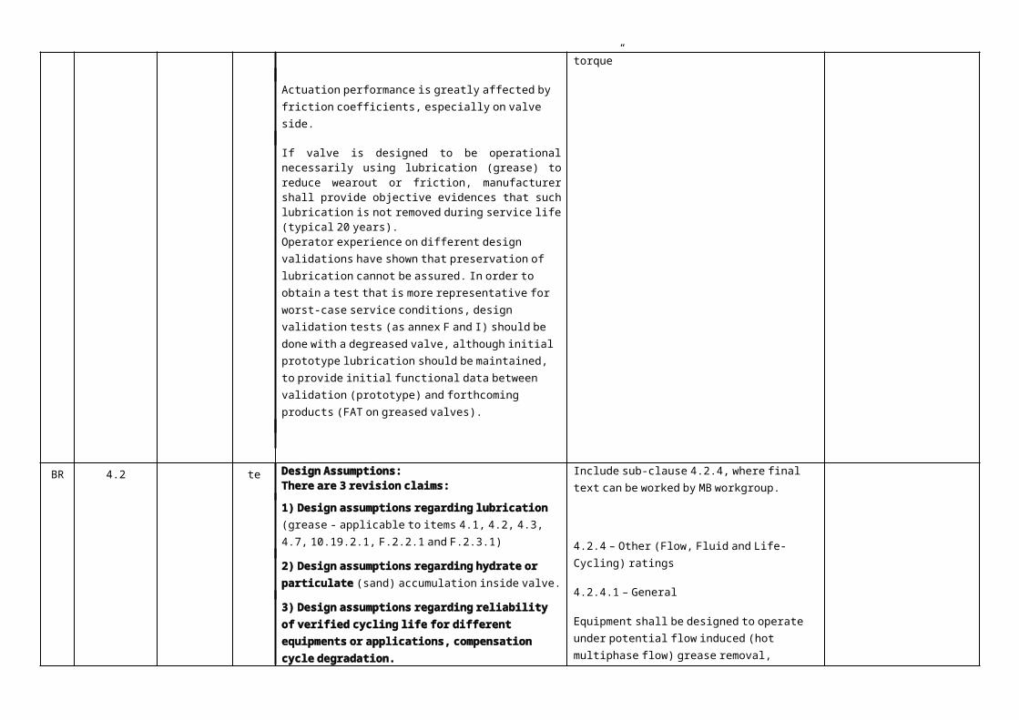
Actuation performance is greatly affected by friction coefficients, especially on valve side.
If valve is designed to be operational necessarily using lubrication (grease) to reduce wearout or friction, manufacturer shall provide objective evidences that such lubrication is not removed during service life (typical 20 years). Operator experience on different design validations have shown that preservation of lubrication cannot be assured. In order to obtain a test that is more representative for worst-case service conditions, design validation tests (as annex F and I) should be done with a degreased valve, although initial prototype lubrication should be maintained, to provide initial functional data between validation (prototype) and forthcoming products (FAT on
Revise text: “Other requirements…” to:
“Other requirements include load capability, cycles, wear-out and lubrication, and operating force or torque”
1 MB = Member body (enter the ISO 3166 two-letter country code, e.g. CN for China; comments from the ISO/CS editing unit are identified by **)2 Type of comment: ge = general te = technical ed = editorial NOTE Columns 1, 2, 4, 5 are compulsory.
page 9 of 40ISO electronic balloting commenting template/version 2001-10
greased valves).
BR 4.2 te Design Assumptions:There are 3 revision claims:
1) Design assumptions regarding lubrication (grease - applicable to items 4.1, 4.2, 4.3, 4.7, 10.19.2.1, F.2.2.1 and F.2.3.1)
2) Design assumptions regarding hydrate or particulate (sand) accumulation inside valve.
3) Design assumptions regarding reliability of verified cycling life for different equipments or applications, compensation cycle degradation.
Actuation performance is greatly affected by friction coefficients, especially on valve side.
If valve is designed to be operational necessarily using lubrication (grease) to reduce wear-out or friction, manufacturer shall provide objective evidences that such lubrication is not removed during service life (typical 20 years).
Operator experience on different design validations have shown that preservation of lubrication cannot be assured. In order to obtain a test that is more representative for worst-case service conditions, design validation tests (as annex F and I) should be done with a degreased valve, although initial prototype lubrication should be maintained, to provide initial functional data between validation (prototype) and forthcoming products (FAT on greased valves).
Regarding fluid with particulates, if valve is lubricated with grease, depending on the amount of filling (see clause 7.4.9.3.3 – “Conduct tests prior to the addition of body-filler grease. Lubrication applied during assembly is acceptable.”) movement restrictions on obturator caused
Include sub-clause 4.2.4, where final text can be worked by MB workgroup.
4.2.4 – Other (Flow, Fluid and Life-Cycling) ratings
4.2.4.1 – General
Equipment shall be designed to operate under potential flow induced (hot multiphase flow) grease removal, hydrate formation or particulate accumulation inside valve causing movement restrictions and increased wear-out, frictions and loads. Manufacturer shall provide designed endurance capability of the equipment, compatible with expected service and cycling for each designed application.
4.2.4.2 – Design considerations
a) Design shall consider the effects caused by grease removal due to flow conditions as increased frictions and loads. This is more significant for SSV and USV equipments.
b) If required by required by purchaser, manufacturer shall demonstrate and validate by testing and calculations at which reliability figures each equipment is capable to operate during its life time and expected number of actuations.
c) Methods to calculate and compensate eventual performance degradation along service life or number of actuations shall be used during design validation and to aid in the establishment of FAT functional criteria.
Template for comments and secretariat observations Date: 2008-09-10 Document: ISO DIS 10423 (4Ed)
1 2 (3) 4 5 (6) (7)
MB1 Clause No./Subclause No./
Annex(e.g. 3.1)
Paragraph/Figure/Table/N
ote(e.g. Table 1)
Type of com-
ment2
Comment (justification for change) by the MB Proposed change by the MB Secretariat observationson each comment submitted
by sand accumulation and increased wear-out (sandpaper effect). In order to avoid or minimize these issues, design shall evaluate these conditions, and appropriate tests shall demonstrate design robustness and endurance to additional wear-out, loads and/or movement restrictions.
Also, flow considerations can be different on gear or ROV operated (typically not operated during high flow conditions) or FSC-actuated valves.
Regarding cycling life of a given equipment (e.g. SSV or USV), the same design can be used with more confidence if PR-2 verified (200 cycles - annex F) and real life actuation is expected to be done a few dozens of operations in say, 20 years of service life. However, if the same valve design is assembled with a FSC actuator and flow assurance (wax / hydrate) demands 1 operation per month, the same design could face more than 200 operations in the same time frame. So, annex F verification should address higher cycling rates than PR-2, in order to provide similar confidence in reliability and endurance requirements.
Other equipments, as swivels and connectors should be capable of more than PR-1 (0 to 3 cycles) but less than PR-2 (200x) and ISO standard should present a minimum requirement, not leaving just as Per Manufacturing Rating (PMR), because manufacturers typically do not provide consistent designed data, expected for operation.
1 MB = Member body (enter the ISO 3166 two-letter country code, e.g. CN for China; comments from the ISO/CS editing unit are identified by **)2 Type of comment: ge = general te = technical ed = editorial NOTE Columns 1, 2, 4, 5 are compulsory.
page 11 of 40ISO electronic balloting commenting template/version 2001-10
Degradation of operation is affected by cycling, service and operational conditions, lubrication and friction figures and shall be explicitly considered in the design.
US 4.2.3.1 Paragraph 2 te ISO 15156 limits H2S partial pressure for certain stainless steels and not for carbon steel. So, standard should not allow use of Stainless steels in place of carbon steels only on basis of mechanical properties.
Reword this paragraph as follows: Provided the mechanical properties can be met, corrosion-resistant alloys may be used in place of stainless steels.
US 4.3.3.1 Paragraph 3 ed Need to clarify ASME BPV referenced in paragraph is an example of a method.
Change the first sentence of the third paragraph to:
In the event … other methods identified by the manufacturer, such as ASME . . . Division 3, shall be used to justify these stresses.
BR 4.7 ed Design Validation
Clarifications regarding SSV and USV normative validation requirements
Reading 10.5, 10.19 and Annex I.1.4 it is understood that SSV and USV shall be PR-2 verified (I.1.4: “The valve to be tested shall be hydrostatically and functionally tested in accordance with 7.4.9 and be PR2-verified”), so validation tests per Annex F PR-2 (F.2.3) are mandatory and shall be performed. However, reading sub-clause 4.7 can induce that Annex F could be optional, being performed only if specified.
Revise text to:
4.7 Design validation
Manufacturers shall document their design validation procedures and the results of performance validation of designs.
Additional validation procedures, including acceptance criteria, are given in Annex F to be used if specified by the manufacturer or purchaser.
Regarding SSVs and USVs , design validation procedures including appropriate acceptance criteria are given in Annexes F and I.
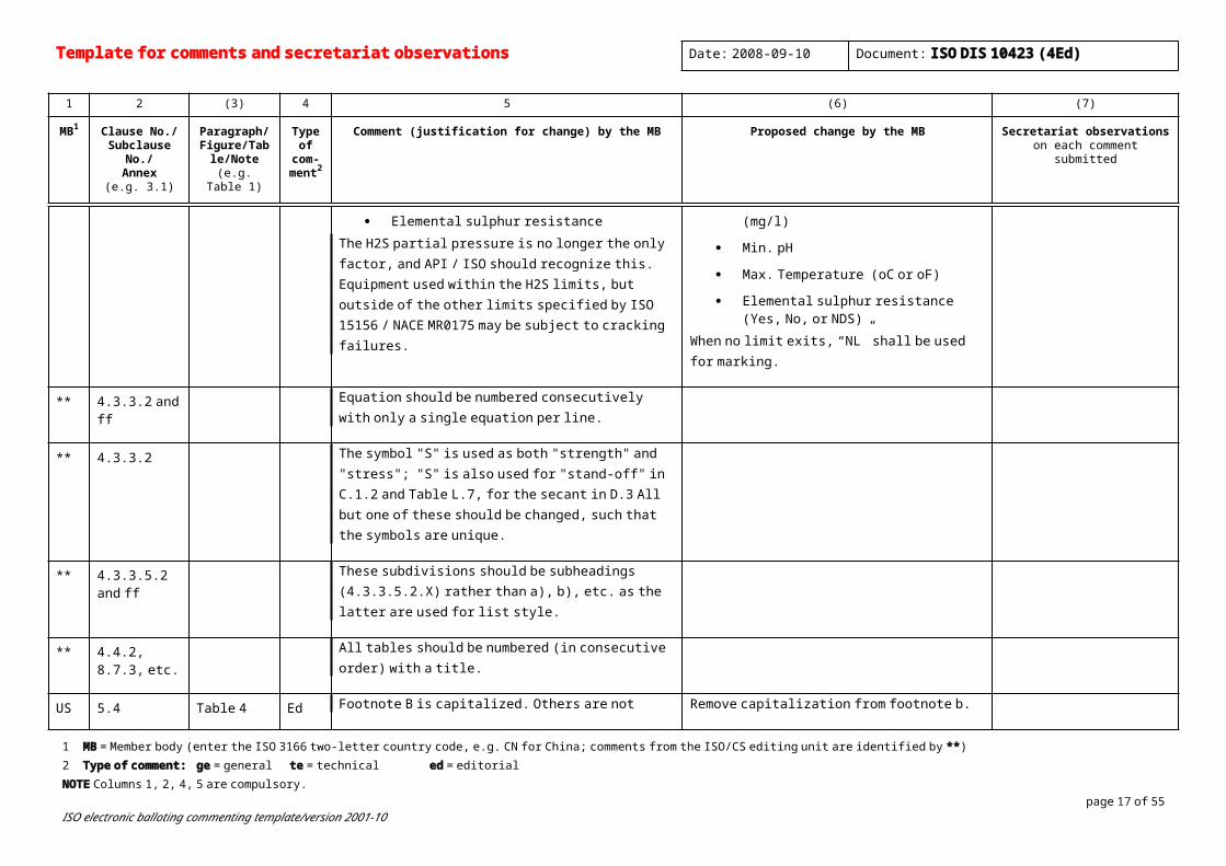
US 4.2.3.2 2 In order to help insure equipment in Material Classes DD, EE, FF, and HH is used in accordance with the environmental limitations specified in NACE ISO 15156 / NACE MR0175, the full limitations need to be marked on the equipment, not just the H2S limit. Depending on the alloy or alloy family, ISO 15156 / NACE MR0175 may impose limits on the following environmental parameters:
Maximum H2S partial pressure
Material classes DD, EE, FF, and HH shall include as part of the designation and marking the environmental limits of the equipment as defined by ISO 15156 / NACE MR0175. The environmental limits shall be determined by reviewing the environmental limits of all the alloys used in an assembly, and then selecting the most restrictive limits. The marking of the environmental limits shall include the following:
Template for comments and secretariat observations Date: 2008-09-10 Document: ISO DIS 10423 (4Ed)
1 2 (3) 4 5 (6) (7)
MB1 Clause No./Subclause No./
Annex(e.g. 3.1)
Paragraph/Figure/Table/N
ote(e.g. Table 1)
Type of com-
ment2
Comment (justification for change) by the MB Proposed change by the MB Secretariat observationson each comment submitted
Maximum Chloride concentration
Minimum pH
Maximum Temperature
Elemental sulphur resistanceThe H2S partial pressure is no longer the only factor, and API / ISO should recognize this. Equipment used within the H2S limits, but outside of the other limits specified by ISO 15156 / NACE MR0175 may be subject to cracking failures.
Max. H2S partial pressure (KPa or PSI)
Max. Chloride concentration (mg/l)
Min. pH
Max. Temperature (oC or oF)
Elemental sulphur resistance (Yes, No, or NDS)
When no limit exits, “NL” shall be used for marking.
** 4.3.3.2 and ff Equation should be numbered consecutively with only a single equation per line.
** 4.3.3.2 The symbol "S" is used as both "strength" and "stress"; "S" is also used for "stand-off" in C.1.2 and Table L.7, for the secant in D.3 All but one of these should be changed, such that the symbols are unique.
** 4.3.3.5.2 and ff
These subdivisions should be subheadings (4.3.3.5.2.X) rather than a), b), etc. as the latter are used for list style.
** 4.4.2, 8.7.3, etc.
All tables should be numbered (in consecutive order) with a title.
US 5.4 Table 4 Ed Footnote B is capitalized. Others are not Remove capitalization from footnote b.
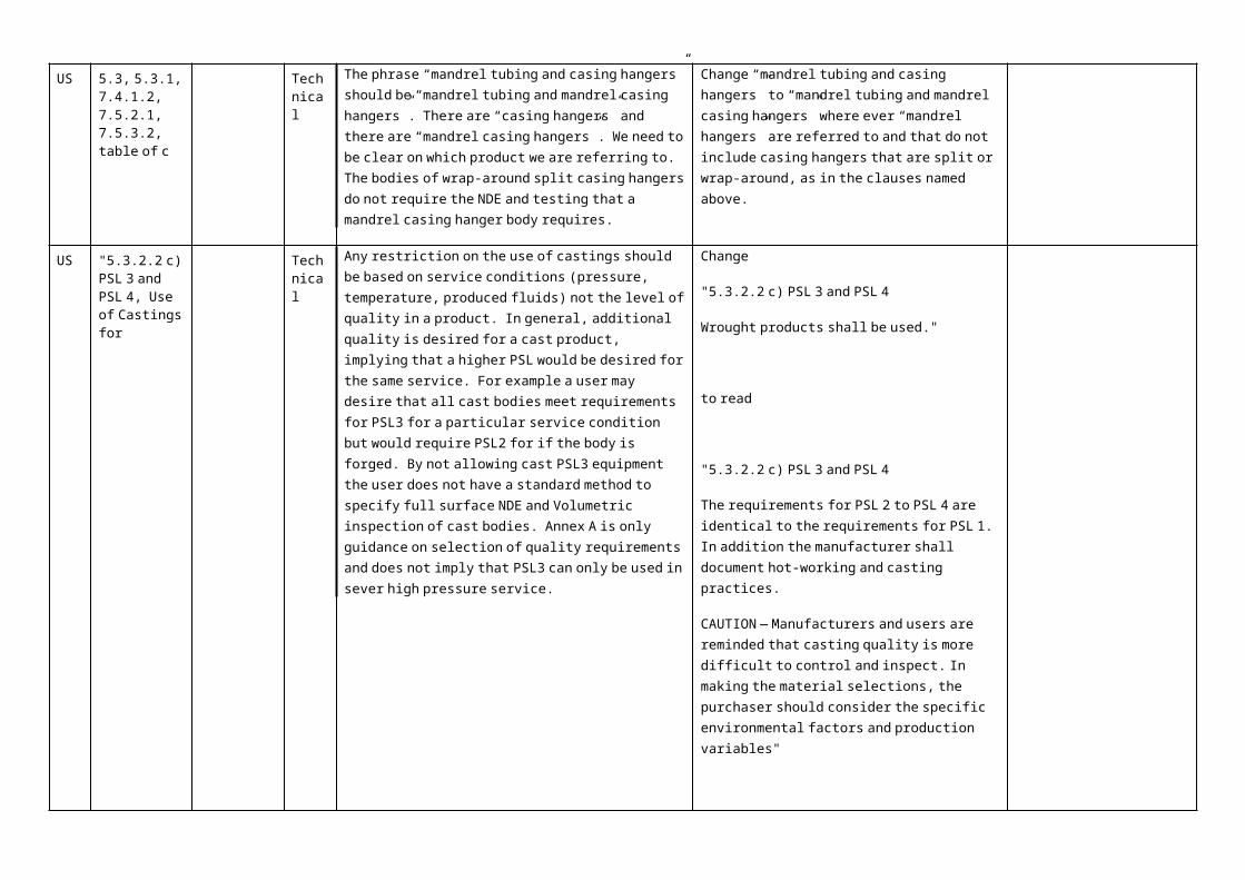
US 5.3, 5.3.1, 7.4.1.2, 7.5.2.1, 7.5.3.2, table of c
Technical
The phrase “mandrel tubing and casing hangers” should be “mandrel tubing and mandrel casing hangers”. There are “casing hangers” and there are “mandrel casing hangers”. We need to be clear on which product we are referring to. The bodies of wrap-around split casing
Change “mandrel tubing and casing hangers” to “mandrel tubing and mandrel casing hangers” where ever “mandrel hangers” are referred to and that do not include casing hangers that are split or
1 MB = Member body (enter the ISO 3166 two-letter country code, e.g. CN for China; comments from the ISO/CS editing unit are identified by **)2 Type of comment: ge = general te = technical ed = editorial NOTE Columns 1, 2, 4, 5 are compulsory.
page 13 of 40ISO electronic balloting commenting template/version 2001-10

hangers do not require the NDE and testing that a mandrel casing hanger body requires.
wrap-around, as in the clauses named above.
US "5.3.2.2 c) PSL 3 and PSL 4, Use of Castings for
Technical
Any restriction on the use of castings should be based on service conditions (pressure, temperature, produced fluids) not the level of quality in a product. In general, additional quality is desired for a cast product, implying that a higher PSL would be desired for the same service. For example a user may desire that all cast bodies meet requirements for PSL3 for a particular service condition but would require PSL2 for if the body is forged. By not allowing cast PSL3 equipment the user does not have a standard method to specify full surface NDE and Volumetric inspection of cast bodies. Annex A is only guidance on selection of quality requirements and does not imply that PSL3 can only be used in sever high pressure service.
Change
"5.3.2.2 c) PSL 3 and PSL 4
Wrought products shall be used."
to read
"5.3.2.2 c) PSL 3 and PSL 4
The requirements for PSL 2 to PSL 4 are identical to the requirements for PSL 1. In addition the manufacturer shall document hot-working and casting practices.
CAUTION — Manufacturers and users are reminded that casting quality is more difficult to control and inspect. In making the material selections, the purchaser should consider the specific environmental factors and production variables"
US 6.3.4.2.3 Figure 5 te ISO 15156-2 Fig 2 is different from this figure. The requirements for welding procedure qualifications/ hardness testing are specified in paragraph 6.3.2.3 d), which states the results shall be in accordance with ISO 15156. Thus the figure must match the ISO 15156 Figure 2.
Change this figure to conform to ISO15156-2 Fig.2
US 7.4.2.1.3(b) 3 A valid method of hardness conversion that has been in the document for years has been replaced by two alternate methods that have never been listed before. ASTM E140 needs to be included in the document as it has been for years.
Hardness conversion to other measurement units shall be in accordance with ASTM E140, ISO 18265, and ISO 15156 (NACE MR0174, see clause 2).

Template for comments and secretariat observations Date: 2008-09-10 Document: ISO DIS 10423 (4Ed)
1 2 (3) 4 5 (6) (7)
MB1 Clause No./Subclause No./
Annex(e.g. 3.1)
Paragraph/Figure/Table/N
ote(e.g. Table 1)
Type of com-
ment2
Comment (justification for change) by the MB Proposed change by the MB Secretariat observationson each comment submitted
US 7.4.6 Heading Te As the document reads now, all ring gaskets are to be PSL 4. I don't believe this is what the workgroup intended.
Remove all PSL references from ring gaskets. They are allowed to be welded per 5.5.3.1 last paragraph.
US 7.4.6 Table 15 Te Dimensional verification incorrect term Replace with Dimensional inspection
US 7.4.7 Entire clause Te As the document reads now, all studs and nuts have the same requirements for all PSL levels thus rendering the PSL designation ineffective.
Remove all PSL references from studs and nuts.
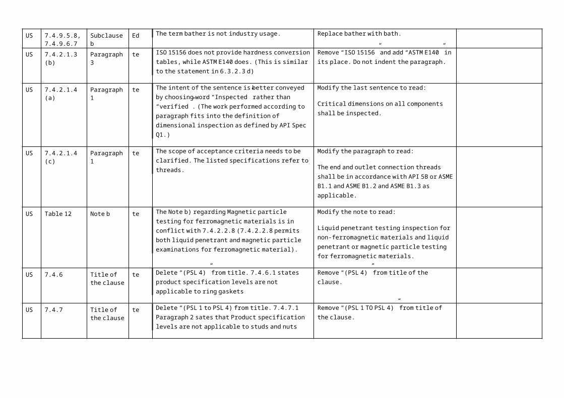
US 7.4.9.5.8, 7.4.9.6.7
Subclause b Ed The term bather is not industry usage. Replace bather with bath.
US 7.4.2.1.3 (b) Paragraph 3 te ISO 15156 does not provide hardness conversion tables, while ASTM E140 does. (This is similar to the statement in 6.3.2.3 d)
Remove “ISO 15156” and add “ASTM E140” in its place. Do not indent the paragraph.
US 7.4.2.1.4 (a) Paragraph 1 te The intent of the sentence is better conveyed by choosing word “Inspected” rather than “verified”. (The work performed according to paragraph fits into the definition of dimensional inspection as defined by API Spec Q1.)
Modify the last sentence to read:
Critical dimensions on all components shall be inspected.
US 7.4.2.1.4 (c) Paragraph 1 te The scope of acceptance criteria needs to be clarified. The listed specifications refer to threads.
Modify the paragraph to read:
The end and outlet connection threads shall be in accordance with API 5B or ASME B1.1 and ASME B1.2 and ASME B1.3 as applicable.
US Table 12 Note b te The Note b) regarding Magnetic particle testing for ferromagnetic materials is in conflict with 7.4.2.2.8 (7.4.2.2.8 permits both liquid penetrant and magnetic particle examinations for ferromagnetic material).
Modify the note to read:
Liquid penetrant testing inspection for non-ferromagnetic materials and liquid penetrant or magnetic particle testing for ferromagnetic
1 MB = Member body (enter the ISO 3166 two-letter country code, e.g. CN for China; comments from the ISO/CS editing unit are identified by **)2 Type of comment: ge = general te = technical ed = editorial NOTE Columns 1, 2, 4, 5 are compulsory.
page 15 of 40ISO electronic balloting commenting template/version 2001-10

materials.
US 7.4.6 Title of the clause
te Delete “(PSL 4)” from title. 7.4.6.1 states product specification levels are not applicable to ring gaskets
Remove “(PSL 4)” from title of the clause.
US 7.4.7 Title of the clause
te Delete “(PSL 1 to PSL 4) from title. 7.4.7.1 Paragraph 2 sates that Product specification levels are not applicable to studs and nuts
Remove “(PSL 1 TO PSL 4)” from title of the clause.
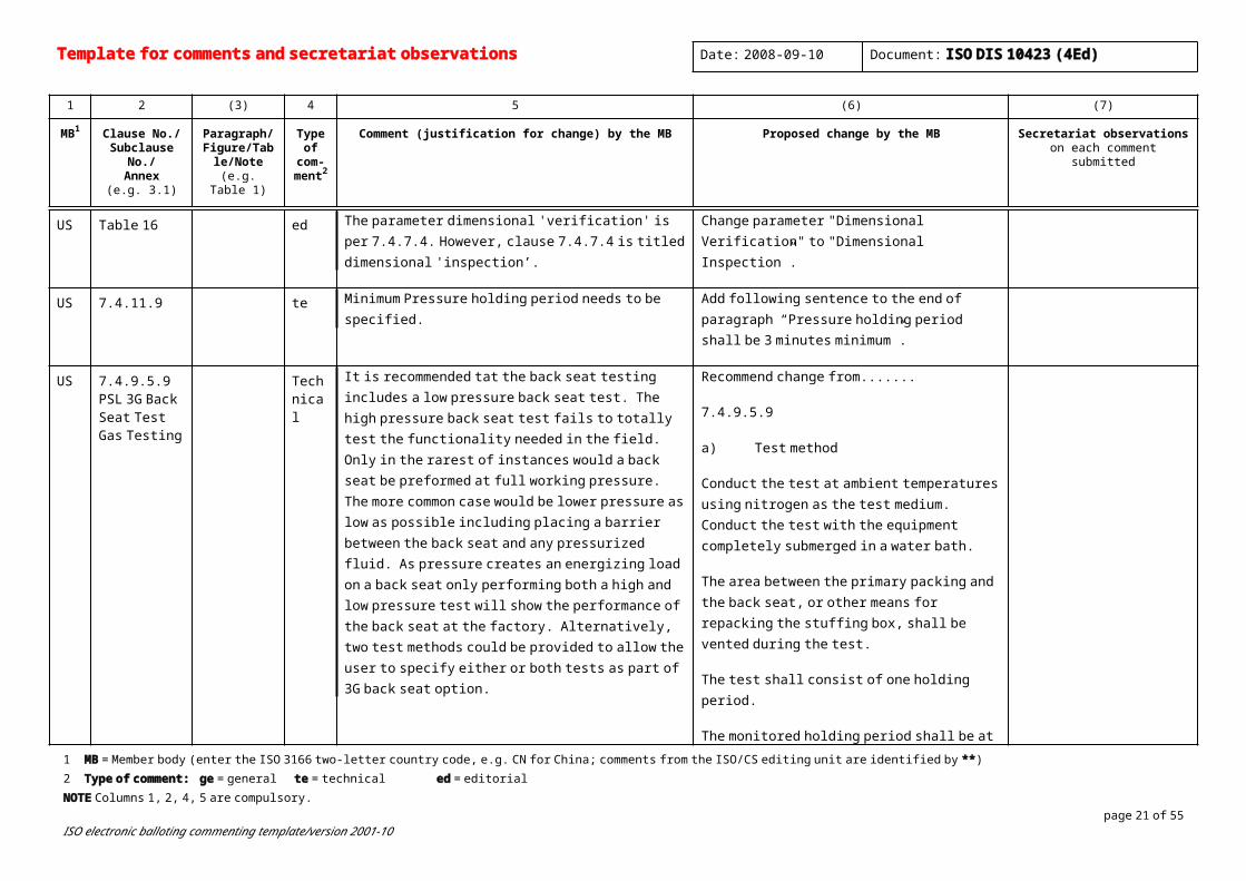
US Table 16 ed The parameter dimensional 'verification' is per 7.4.7.4. However, clause 7.4.7.4 is titled dimensional 'inspection’.
Change parameter "Dimensional Verification" to "Dimensional Inspection”.
US 7.4.11.9 te Minimum Pressure holding period needs to be specified. Add following sentence to the end of paragraph “Pressure holding period shall be 3 minutes minimum”.
US 7.4.9.5.9 PSL 3G Back Seat Test Gas Testing
Technical
It is recommended tat the back seat testing includes a low pressure back seat test. The high pressure back seat test fails to totally test the functionality needed in the field. Only in the rarest of instances would a back seat be preformed at full working pressure. The more common case would be lower pressure as low as possible including placing a barrier between the back seat and any pressurized fluid. As pressure creates an energizing load on a back seat only performing both a high and low pressure test will show the performance of the back seat at the factory. Alternatively, two test methods could be provided to allow the user to specify either or both tests as part of 3G back seat option.
Recommend change from.......
7.4.9.5.9
a) Test method
Conduct the test at ambient temperatures using nitrogen as the test medium. Conduct the test with the equipment completely submerged in a water bath.
The area between the primary packing and the back seat, or other means for repacking the stuffing box, shall be vented during the test.
The test shall consist of one holding period.
The monitored holding period shall be at the rated working pressure.
The monitored holding period shall be a minimum of 15 min.
b) Acceptance criteria
No visible bubbles shall appear in the water bath during the holding period. A maximum reduction of the gas test pressure of 2,0 MPa (300 psi) is

Template for comments and secretariat observations Date: 2008-09-10 Document: ISO DIS 10423 (4Ed)
1 2 (3) 4 5 (6) (7)
MB1 Clause No./Subclause No./
Annex(e.g. 3.1)
Paragraph/Figure/Table/N
ote(e.g. Table 1)
Type of com-
ment2
Comment (justification for change) by the MB Proposed change by the MB Secretariat observationson each comment submitted
acceptable as long as there are no visible bubbles in the water bath during the holding period.
Change To Read.......
a) Test method
Conduct the test at ambient temperatures using nitrogen as the test medium. Conduct the test with the equipment completely submerged in a water bath.
Testing shall consist of two, monitored, holding periods.
The primary test pressure shall be the rated working pressure.
The primary-test monitored holding period shall be a minimum of 15 min.
Reduce the pressure to zero between the primary and secondary holding periods.
The secondary test pressure shall be at 2,0 MPa (300 psi) „b 10 %.
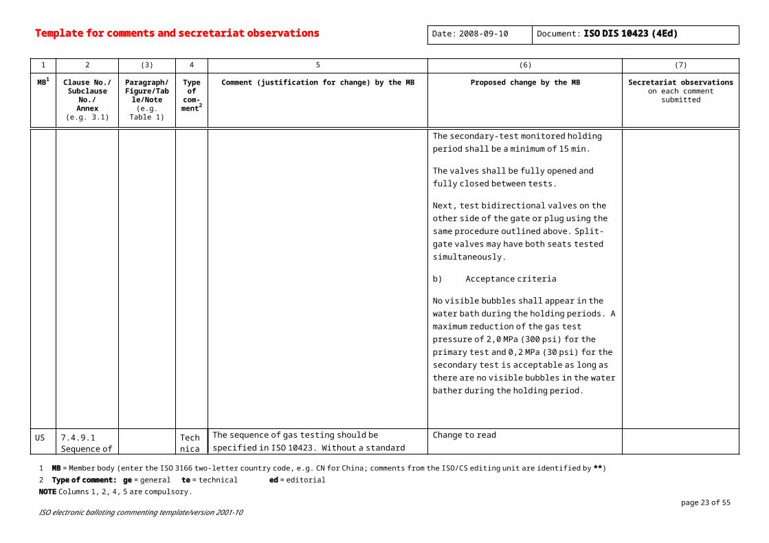
The secondary-test monitored holding period shall be a minimum of 15 min.
The valves shall be fully opened and fully closed between tests.
Next, test bidirectional valves on the other side of 1 MB = Member body (enter the ISO 3166 two-letter country code, e.g. CN for China; comments from the ISO/CS editing unit are identified by **)2 Type of comment: ge = general te = technical ed = editorial NOTE Columns 1, 2, 4, 5 are compulsory.
page 17 of 40ISO electronic balloting commenting template/version 2001-10
the gate or plug using the same procedure outlined above. Split-gate valves may have both seats tested simultaneously.
b) Acceptance criteria
No visible bubbles shall appear in the water bath during the holding periods. A maximum reduction of the gas test pressure of 2,0 MPa (300 psi) for the primary test and 0,2 MPa (30 psi) for the secondary test is acceptable as long as there are no visible bubbles in the water bather during the holding period.
US 7.4.9.1 Sequence of Hydro and Gas Testing
Technical
The sequence of gas testing should be specified in ISO 10423. Without a standard procedure it is difficult for user to determine if testing is comparable. For example performing all the test on one seat prior to testing the other. Performing all low pressure tests before high pressure tests. Performing a gas body test before performing a stem pack test. If a test procedure is documented by a manufacture, can the test sequence be changed arbitrarily on the shop floor? As the test sequence is important to demonstrate performance of the equipment a strict test sequence is advised.
Change to read
7.4.9.1 General
All hydrostatic body testing shall be preformed first. Hydrostatic valve seat testing shall be performed prior to any gas testing. Gas body and back seat tests, if required, shall be preformed performed prior to any gas seat testing. The sequence of tests may be not be varied, except that bodies previously hydro tested do not require retesting. The drift test shall be performed after the equipment has been assembled, operated and tested.
US 7.2.2.1 Pressure Measuring Devices
Technical
It needs to be documented that changing the accuracy of the gauge from +/- 0.5% to +/- 2% does not change the accuracy of the gage to a change in pressure. Pressure testing acceptance criteria are defined by an allowable drop or rate of change.
Maintain original requirements unless it can be verified that the change in accuracy of the pressure gauge does not have an effect on the acceptance criteria on pressure tests.
As reading accuracy is only one aspect of consideration, recommend defining appropriate
Template for comments and secretariat observations Date: 2008-09-10 Document: ISO DIS 10423 (4Ed)
1 2 (3) 4 5 (6) (7)
MB1 Clause No./Subclause No./
Annex(e.g. 3.1)
Paragraph/Figure/Table/N
ote(e.g. Table 1)
Type of com-
ment2
Comment (justification for change) by the MB Proposed change by the MB Secretariat observationson each comment submitted
attributes, including safety, from a standard such as BS EN 837- part 1 and part 2 or ASTM B40.1 (vibration or fatigue requirements, over-ranging, blow out back or disk, visible stop pin, shatter resistant safety glass)
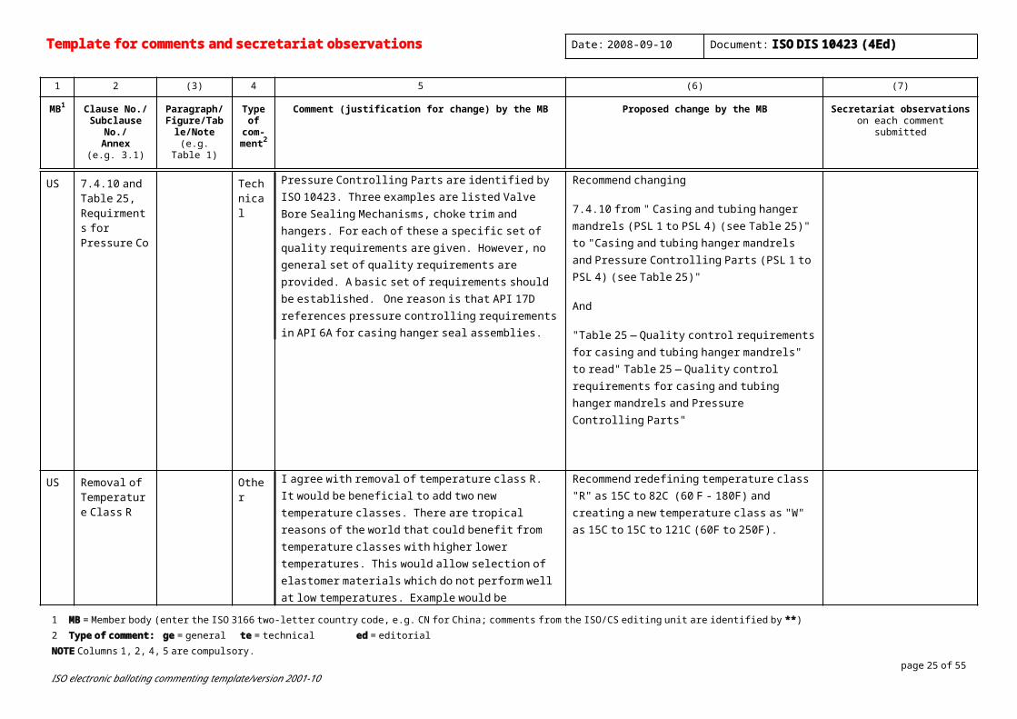
US 7.4.10 and Table 25, Requirments for Pressure Co
Technical
Pressure Controlling Parts are identified by ISO 10423. Three examples are listed Valve Bore Sealing Mechanisms, choke trim and hangers. For each of these a specific set of quality requirements are given. However, no general set of quality requirements are provided. A basic set of requirements should be established. One reason is that API 17D references pressure controlling requirements in API 6A for casing hanger seal assemblies.
Recommend changing
7.4.10 from " Casing and tubing hanger mandrels (PSL 1 to PSL 4) (see Table 25)" to "Casing and tubing hanger mandrels and Pressure Controlling Parts (PSL 1 to PSL 4) (see Table 25)"
And
"Table 25 — Quality control requirements for casing and tubing hanger mandrels" to read" Table 25 — Quality control requirements for casing and tubing hanger mandrels and Pressure Controlling Parts"
US Removal of Temperature Class R
Other I agree with removal of temperature class R. It would be beneficial to add two new temperature classes. There are tropical reasons of the world that could benefit from temperature classes with higher lower temperatures. This would allow selection of elastomer materials which do not perform well at low temperatures. Example would be Tetrafluoroethylene (Aflas tm).
Recommend redefining temperature class "R" as 15C to 82C (60 F - 180F) and creating a new temperature class as "W" as 15C to 15C to 121C (60F to 250F).
US 7.4.2.2.8 Surface NDE -
Technical
Current proposal in ISO 10423 Recommended change: Leave wording as is.
1 MB = Member body (enter the ISO 3166 two-letter country code, e.g. CN for China; comments from the ISO/CS editing unit are identified by **)2 Type of comment: ge = general te = technical ed = editorial NOTE Columns 1, 2, 4, 5 are compulsory.
page 19 of 40ISO electronic balloting commenting template/version 2001-10

Ferromagnetic materials
b) Test method
All ferromagnetic materials shall be examined in accordance with procedures specified in ASTM E 709 (MT) or ASME E165 (PT). Prods are not permitted on well-fluid surfaces or sealing surfaces.
Rationale for recommended change
MT of ferromagnetic material offer the following advantages over PT:
Better sensitivity to surface and near-surface flaws.
Offers inspection capability of rough or cast surfaces.
Examination materials and their disposal are less costly than penetrant.
PT has the following disadvantages when compared to MT of ferromagnetic materials:
Surfaces must be free of any oils or residue.
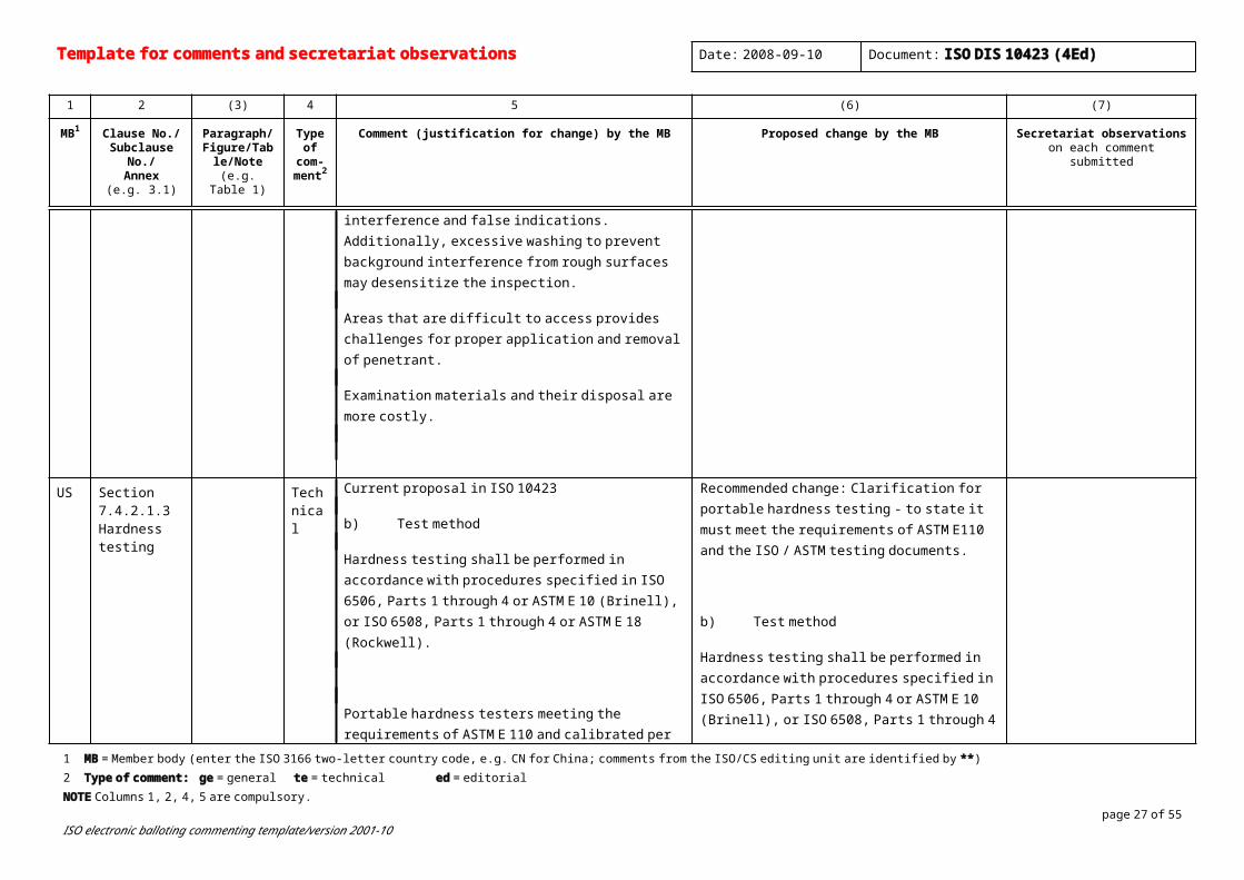
Rough machined forgings or castings are difficult to inspect due to rough surfaces trapping penetrant making it more difficult to remove. This can cause background interference and false indications. Additionally, excessive washing to prevent background interference from rough surfaces may desensitize the inspection.
Areas that are difficult to access provides challenges for proper application and removal of penetrant.
Examination materials and their disposal are more costly.
b) Test method
All ferromagnetic materials shall be examined in accordance with procedures specified in ASTM E 709 (MT). Prods are not permitted on well-fluid surfaces or sealing surfaces
US Section 7.4.2.1.3 Hardness
Technical
Current proposal in ISO 10423 Recommended change: Clarification for portable hardness testing - to state it must meet the requirements of ASTM E110 and the ISO / ASTM
Template for comments and secretariat observations Date: 2008-09-10 Document: ISO DIS 10423 (4Ed)
1 2 (3) 4 5 (6) (7)
MB1 Clause No./Subclause No./
Annex(e.g. 3.1)
Paragraph/Figure/Table/N
ote(e.g. Table 1)
Type of com-
ment2
Comment (justification for change) by the MB Proposed change by the MB Secretariat observationson each comment submitted
testing b) Test method
Hardness testing shall be performed in accordance with procedures specified in ISO 6506, Parts 1 through 4 or ASTM E 10 (Brinell), or ISO 6508, Parts 1 through 4 or ASTM E 18 (Rockwell).
Portable hardness testers meeting the requirements of ASTM E 110 and calibrated per ISO 6506 or ASTM E 10, or ISO 6508 or ASTM E 18, as applicable, may be used for hardness testing.
Hardness conversion to other measurement units shall be in accordance with ISO 18265 and ISO 15156 (NACE MR 0175, see clause 2).
Rationale for EM recommended change
Reference to calibrate per ISO 6506 / ASTM E10 or ISO 6508 / ASTM E18 as applicable is inadequate. Calibration is only one requirement of many referenced in the ASTM and ISO documents for hardness testing. For example, daily verification checks are referenced in the procedures to ensure that hardness testing equipment is working properly on a daily basis, calibration is required for test blocks as well as equipment.
testing documents.
b) Test method
Hardness testing shall be performed in accordance with procedures specified in ISO 6506, Parts 1 through 4 or ASTM E 10 (Brinell), or ISO 6508, Parts 1 through 4 or ASTM E 18 (Rockwell).
Portable hardness testers meeting the requirements of ASTM E 110 and ISO 6506 or ASTM E 10, or ISO 6508 or ASTM E 18, as applicable, may be used for hardness testing.
Hardness conversion to other measurement units shall be in accordance with ISO 18265 and ISO 15156 (NACE MR 0175, see clause 2).
1 MB = Member body (enter the ISO 3166 two-letter country code, e.g. CN for China; comments from the ISO/CS editing unit are identified by **)2 Type of comment: ge = general te = technical ed = editorial NOTE Columns 1, 2, 4, 5 are compulsory.
page 21 of 40ISO electronic balloting commenting template/version 2001-10
US Table 12, Note b.
Editorial
Table should be consistent with Clause 7.4.2.2.8 in allowing PT to be use as well as MP on Ferromagnetic material.
Ref 7.4.2.2.8
b) Test method
All ferromagnetic materials shall be examined in accordance with procedures specified in ASTM E 709 (MT) or ASME E165 (PT). Prods are not permitted on well-fluid surfaces or sealing surfaces.
Table 12 b Liquid penetrant testing inspection for non-ferromagnetic materials, and magnetic particle testing or liquid penetrant testing inspection for ferromagnetic material.
US 7.4.2.2.14 Technical
Change paragraph to allow for proper UT inspection methods to account for the near field effect. The proposed wording is identical to Clause 7.4.2.3.15
a) Sampling
100 % of all pressure-containing welds shall be examined by either radiography or ultrasonic methods after all welding, post-weld heat treatment and prior to machining operations that limit effective interpretation of the results of the examination. All repair welds where the repair is greater than 25 % of the original wall thickness or 25 mm (1 in), whichever is less, shall be examined by either radiography or ultrasonic methods after all welding and post-weld heat treatment. Examinations shall include at least 13 mm (1/2 in) of adjacent base metal on all sides of the weld.
US Clause 7.4.9.1 Editorial
Consistent wording would be to use the term “gas testing” instead to “gas test” in the second sentence of this clause.
All hydrostatic body testing and all hydrostatic valve seat testing shall be performed prior to any gas testing. The sequence of gas testing may be varied at the option of the manufacturer. The drift test shall be performed after the equipment has been assembled, operated and tested. The sequence of other tests shall be at the option of
Template for comments and secretariat observations Date: 2008-09-10 Document: ISO DIS 10423 (4Ed)
1 2 (3) 4 5 (6) (7)
MB1 Clause No./Subclause No./
Annex(e.g. 3.1)
Paragraph/Figure/Table/N
ote(e.g. Table 1)
Type of com-
ment2
Comment (justification for change) by the MB Proposed change by the MB Secretariat observationson each comment submitted
the manufacturer.
US 7.4.9.6.8 Editorial
The word “bather” should be “bath”. No visible bubbles shall appear in the water bath during the holding periods. A maximum reduction of the gas test pressure of 2,0 MPa (300 psi) for the primary test holding period and 0,2 MPa (30 psi) for the secondary test holding period is acceptable as long as there are no visible bubbles in the water bath during the holding period.
US Clause 7.4.2.2.14 b)
The current requirement for radiographic examination are incomplete as they do not give guidance for the quality level.
Justification: The 2% is an equivalent sensitivity after calculations but does not tell you guidance for the "quality level". The "2-2T quality level", will establish that the penetrameter to be used is 2% of the material thickness, and that "2T" (diameter of the hole=2 x wall thickness) is the size of the hole that must be visible in order that the films and the process must be quality acceptable.
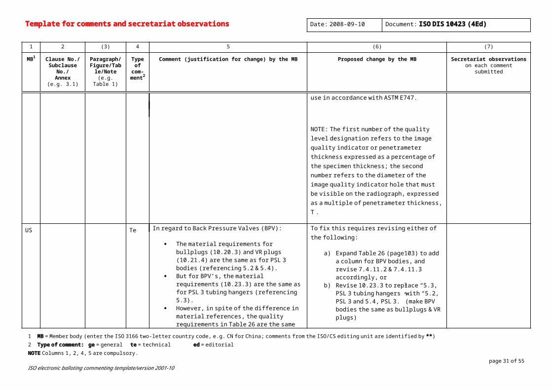
Radiographic examinations shall be performed in accordance with procedures specified in ASTM E94, to a minimum equivalent sensitivity of 2% and a 2-2T quality level. Both X-ray and gamma-ray radiation sources are acceptable within the inherent thickness range limitation of each. Real-time imaging and recording/enhancement methods may be used if the manufacturer has documented proof that these methods will result in a minimum equivalent sensitivity of 2% and a 2-2T quality level. Wire-type image quality indicators are acceptable for use in accordance with ASTM E747.
NOTE: The first number of the quality level designation refers to the image quality indicator or penetrameter thickness expressed as a percentage of the specimen thickness; the second number refers to the diameter of the image quality indicator hole that must be visible on the
1 MB = Member body (enter the ISO 3166 two-letter country code, e.g. CN for China; comments from the ISO/CS editing unit are identified by **)2 Type of comment: ge = general te = technical ed = editorial NOTE Columns 1, 2, 4, 5 are compulsory.
page 23 of 40ISO electronic balloting commenting template/version 2001-10
radiograph, expressed as a multiple of penetrameter thickness, T .
US Te In regard to Back Pressure Valves (BPV):
The material requirements for bullplugs (10.20.3) and VR plugs (10.21.4) are the same as for PSL 3 bodies (referencing 5.2 & 5.4).
But for BPV’s, the material requirements (10.23.3) are the same as for PSL 3 tubing hangers (referencing 5.3).
However, in spite of the difference in material references, the quality requirements in Table 26 are the same for all three items.
The confusion arises when one tries to deduce the tensile testing and impact testing requirements for BPV’s:
o Per table 26, 7.4.11.2, and 7.4.11.3 requirements for BPV’s, tensile testing should be per 5.4.2.3 and impact testing should be per 5.4.2.4.
o But per subclause 5.3 requirements for BPV’s, tensile testing should be per 5.3.5.2 and impact testing should be per 5.3.5.3.
To fix this requires revising either of the following:
a) Expand Table 26 (page103) to add a column for BPV bodies, and revise 7.4.11.2 & 7.4.11.3 accordingly, or
b) Revise 10.23.3 to replace “5.3, PSL 3 tubing hangers” with “5.2, PSL 3 and 5.4, PSL 3.” (make BPV bodies the same as bullplugs & VR plugs)
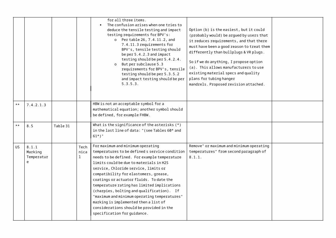
Option (b) is the easiest, but it could (probably would) be argued by users that it reduces requirements, and that there must have been a good reason to treat them differently than bullplugs & VR plugs.
So if we do anything, I propose option (a). This allows manufacturers to use existing material specs and quality plans for tubing hanger mandrels. Proposed revision attached.
** 7.4.2.1.3 HBW is not an acceptable symbol for a mathematical equation; another symbol should be defined, for example FHBW.
** 8.5 Table 31 What is the significance of the asterisks (*) in the last line of data: "(see Tables 60* and 61*)"
US 8.1.1 Marking Temperature
Technical
For maximum and minimum operating temperatures to be defined s service condition needs to be defined. For example temperature limits could be due to materials in H2S service, Chloride service, limits or compatibility for elastomers, grease, coatings or actuator fluids. To date the temperature rating has limited implications (charpies, bolting and qualification). If "maximum and minimum operating temperatures" marking is implemented then a list of considerations should be provided in the
Remove" or maximum and minimum operating temperatures" from second paragraph of 8.1.1.

Template for comments and secretariat observations Date: 2008-09-10 Document: ISO DIS 10423 (4Ed)
1 2 (3) 4 5 (6) (7)
MB1 Clause No./Subclause No./
Annex(e.g. 3.1)
Paragraph/Figure/Table/N
ote(e.g. Table 1)
Type of com-
ment2
Comment (justification for change) by the MB Proposed change by the MB Secretariat observationson each comment submitted
specification for guidance.
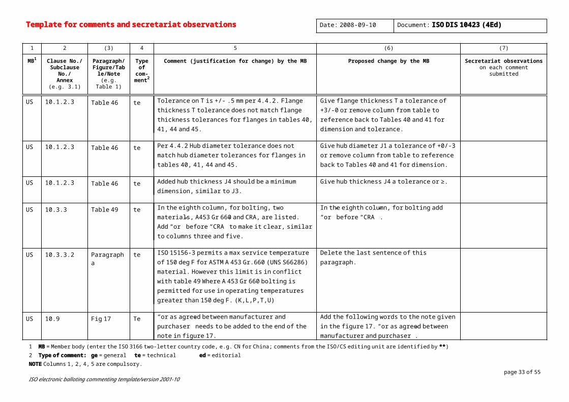
US 10.1.2.3 Table 46 te Tolerance on T is +/- .5 mm per 4.4.2. Flange thickness T tolerance does not match flange thickness tolerances for flanges in tables 40, 41, 44 and 45.
Give flange thickness T a tolerance of +3/-0 or remove column from table to reference back to Tables 40 and 41 for dimension and tolerance.
US 10.1.2.3 Table 46 te Per 4.4.2 Hub diameter tolerance does not match hub diameter tolerances for flanges in tables 40, 41, 44 and 45.
Give hub diameter J1 a tolerance of +0/-3 or remove column from table to reference back to Tables 40 and 41 for dimension.
US 10.1.2.3 Table 46 te Added hub thickness J4 should be a minimum dimension, similar to J3.
Give hub thickness J4 a tolerance or ≥.
US 10.3.3 Table 49 te In the eighth column, for bolting, two materials, A453 Gr 660 and CRA, are listed. Add “or” before “CRA” to make it clear, similar to columns three and five.
In the eighth column, for bolting add “or” before “CRA” .
US 10.3.3.2 Paragraph a te ISO 15156-3 permits a max service temperature of 150 deg F for ASTM A 453 Gr.660 (UNS S66286) material. However this limit is in conflict with table 49 Where A 453 Gr 660 bolting is permitted for use in operating temperatures greater than 150 deg F. (K,L,P,T,U)
Delete the last sentence of this paragraph.
US 10.9 Fig 17 Te “or as agreed between manufacturer and purchaser” needs to be added to the end of the note in figure 17.
These additional words are included at the end of the note given in Fig 18, and these words are applicable to Fig 17 also.
Add the following words to the note given in the figure 17. “or as agreed between manufacturer and purchaser”.
** 10.1.4 "this clause" - ?Clause 10 or the 10.1.4
1 MB = Member body (enter the ISO 3166 two-letter country code, e.g. CN for China; comments from the ISO/CS editing unit are identified by **)2 Type of comment: ge = general te = technical ed = editorial NOTE Columns 1, 2, 4, 5 are compulsory.
page 25 of 40ISO electronic balloting commenting template/version 2001-10
** 10.2.4, 10.11.6 and ff
If Tables 63, 77 are deleted, the subsequent tables should be renumbered to be consecutive.
** 10.11.1, 10.12.1, etc.
"this subclause" - ?10.11 or 10.11.1
US 10.5.3.8 Operating mechanisms
Ed Gate valves shall be supplied with a handwheel…
Reason: Actuated valves look funny with handwheels.
Manually operated gate valves shall be supplied with a handwheel.
US 10.5.3.8 Ed All handwheels shall be spoked and replaceable while in service.
Reason: Several past and present manufacturers have made handwheels that do not have the traditional circular-rim-and-spoke shape and these have been well-accepted for years, they are equally functional and lighter in weight.
All handwheels shall be replaceable while in service.
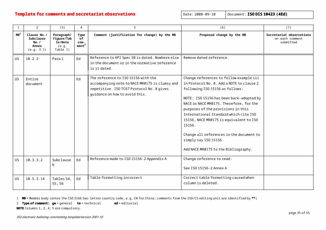
US 10.2.3 Para 1 Ed Reference to API Spec 5B is dated. Nowhere else in the document or in the normative reference is it dated.
Remove dated reference.
US Entire document
Ed The reference to ISO 15156 with the accompanying note to NACE MR0175 is clumsy and repetitive. ISO TC67 Protocol No. 8 gives guidance on how to avoid this.
Change references to follow example iii in Protocol No. 8. Add a NOTE to clause 2 following ISO 15156 as follows:
NOTE: ISO 15156 has been back-adopted by NACE as NACE MR0175. Therefore, for the purposes of the provisions in this International Standard which cite ISO 15156, NACE MR0175 is equivalent to ISO 15156.
Change all references in the document to simply say ISO 15156.

Template for comments and secretariat observations Date: 2008-09-10 Document: ISO DIS 10423 (4Ed)
1 2 (3) 4 5 (6) (7)
MB1 Clause No./Subclause No./
Annex(e.g. 3.1)
Paragraph/Figure/Table/N
ote(e.g. Table 1)
Type of com-
ment2
Comment (justification for change) by the MB Proposed change by the MB Secretariat observationson each comment submitted
Add NACE MR0175 to the Bibliography.
US 10.3.3.2 Subclause b Ed Reference made to ISO 15156-2 Appendix A Change reference to read:
See ISO 15156-2 Annex A
US 10.5.3.14 Tables 54, 55, 56
Ed Table formatting incorrect Correct table formatting caused when column is deleted.
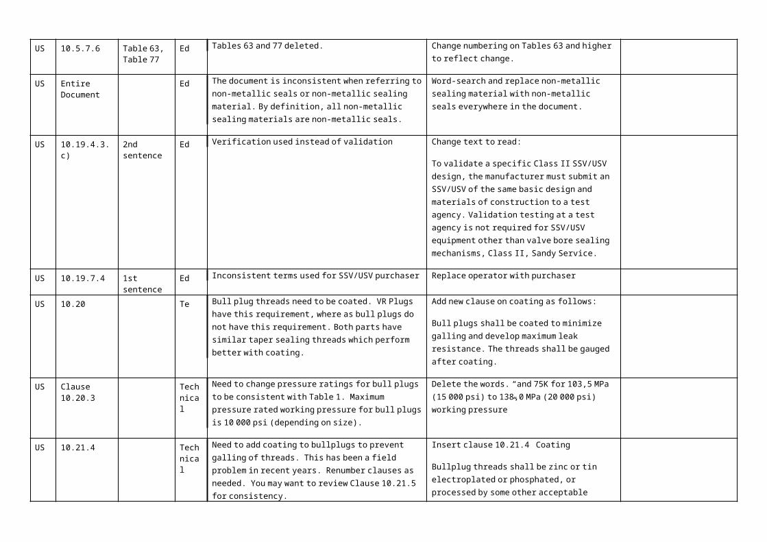
US 10.5.7.6 Table 63, Table 77
Ed Tables 63 and 77 deleted. Change numbering on Tables 63 and higher to reflect change.
US Entire Document
Ed The document is inconsistent when referring to non-metallic seals or non-metallic sealing material. By definition, all non-metallic sealing materials are non-metallic seals.
Word-search and replace non-metallic sealing material with non-metallic seals everywhere in the document.
US 10.19.4.3. c) 2nd sentence
Ed Verification used instead of validation Change text to read:
To validate a specific Class II SSV/USV design, the manufacturer must submit an SSV/USV of the same basic design and materials of construction to a test agency. Validation testing at a test agency is not required for SSV/USV equipment other than valve bore sealing mechanisms, Class II, Sandy Service.
US 10.19.7.4 1st sentence Ed Inconsistent terms used for SSV/USV purchaser Replace operator with purchaser
US 10.20 Te Bull plug threads need to be coated. VR Plugs have this requirement, where as bull plugs do not have this requirement. Both parts have similar taper sealing threads which perform better with coating.
Add new clause on coating as follows:
Bull plugs shall be coated to minimize galling and develop maximum leak resistance. The threads
1 MB = Member body (enter the ISO 3166 two-letter country code, e.g. CN for China; comments from the ISO/CS editing unit are identified by **)2 Type of comment: ge = general te = technical ed = editorial NOTE Columns 1, 2, 4, 5 are compulsory.
page 27 of 40ISO electronic balloting commenting template/version 2001-10
shall be gauged after coating.
US Clause 10.20.3
Technical
Need to change pressure ratings for bull plugs to be consistent with Table 1. Maximum pressure rated working pressure for bull plugs is 10 000 psi (depending on size).
Delete the words. “and 75K for 103,5 MPa (15 000 psi) to 138,0 MPa (20 000 psi) working pressure”
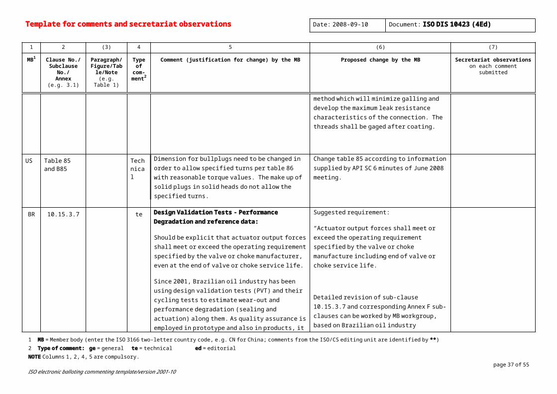
US 10.21.4 Technical
Need to add coating to bullplugs to prevent galling of threads. This has been a field problem in recent years. Renumber clauses as needed. You may want to review Clause 10.21.5 for consistency.
Insert clause 10.21.4 Coating
Bullplug threads shall be zinc or tin electroplated or phosphated, or processed by some other acceptable method which will minimize galling and develop the maximum leak resistance characteristics of the connection. The threads shall be gaged after coating.
US Table 85 and B85
Technical
Dimension for bullplugs need to be changed in order to allow specified turns per table 86 with reasonable torque values. The make up of solid plugs in solid heads do not allow the specified turns.
Change table 85 according to information supplied by API SC 6 minutes of June 2008 meeting.
BR 10.15.3.7 te Design Validation Tests - Performance Degradation and reference data:
Should be explicit that actuator output forces shall meet or exceed the operating requirement specified by the valve or choke manufacturer, even at the end of valve or choke service life.
Since 2001, Brazilian oil industry has been using design validation tests (PVT) and their cycling tests to estimate wear-out and performance degradation (sealing and actuation) along them. As quality assurance is employed in prototype and also in products, it is considered that PVT results are representative of design and can be used as reference to future product valves. This method is capable to estimate the expected performance degradation due to cycling, which can be used as a FAT acceptance criteria parcel.
Suggested requirement:
“Actuator output forces shall meet or exceed the operating requirement specified by the valve or choke manufacture including end of valve or choke service life.”
Detailed revision of sub-clause 10.15.3.7 and corresponding Annex F sub-clauses can be worked by MB workgroup, based on Brazilian oil industry experience.
BR 10.15.6.2 te Actuator functional test – preliminary and final assembly:
Revise text to:

Template for comments and secretariat observations Date: 2008-09-10 Document: ISO DIS 10423 (4Ed)
1 2 (3) 4 5 (6) (7)
MB1 Clause No./Subclause No./
Annex(e.g. 3.1)
Paragraph/Figure/Table/N
ote(e.g. Table 1)
Type of com-
ment2
Comment (justification for change) by the MB Proposed change by the MB Secretariat observationson each comment submitted
Fluid for hydraulic actuators:
Although preliminary functional test can be used to speed up overall FAT of assembled equipment (or valve + actuator assembly), it is necessary a final functional test to demonstrate the proper assembly and operation. This final functional test of assembled equipment can identify eventual assembly problems and misalignments between actuator valve.
Original text: “Test media for hydraulic actuators shall be a suitable hydraulic fluid or gas such as air or nitrogen”. See also F.2.4.
10.15.6.2 Functional testing
Each actuator shall be subjected to a functional test to demonstrate proper assembly and operation. Although preliminary partial functional test can be used to speed up overall FAT of assembled equipment, the actuator shall be tested with the equipment for which it is intended.
Test media for pneumatic actuators shall be a gas such as air or nitrogen.
Test media for hydraulic actuators shall be a suitable hydraulic fluid.
Test power supplied to electric actuators shall be in accordance with the electrical design
requirements.
BR 10.15.6.2. b Operational Test – definition of “Smoothly” :
“The actuator shall operate smoothly in both directions”
Even for a product assembly (valve-actuator) without available validation test data, it is possible to detect if the assembly is able to operate “smoothly” or not, depending how a test is performed.
Revision of 10.15.6.2.b can be worked by MB workgroup.
Initial suggestion could be:
1) Standardize the functional test method (click on attached PDF icon) – workgroup activity;
2) Definition of “smoothly” in sub-clause 3.1
1 MB = Member body (enter the ISO 3166 two-letter country code, e.g. CN for China; comments from the ISO/CS editing unit are identified by **)2 Type of comment: ge = general te = technical ed = editorial NOTE Columns 1, 2, 4, 5 are compulsory.
page 29 of 40ISO electronic balloting commenting template/version 2001-10

This is an important reason for test standardization, as better described in comments for sub-clauses F.2.2.2.1 and F.2.3.3.1, not only for “smoothly” definition but also to detect lack of repetitive (consistent) operation.
It can be reminded that it also provides objective evidences of acceptable functional behaviour in a standardized way - qualitative (as signature “shape”) and quantitative (A1..A5, R1..R4 key-point tables).
The next figure was obtained from a “non-smooth” (stick-slip behavior) operation of a USV gate valve, taken during FAT @ 5 ksi.
Although not complete definition, a smooth operation is lack of stick-slip (“clicking”) effects, mainly present on actuations under high differential pressures.
Also, comparing data dispersion of key-points (ex.: “std.dev.” or “max-min”) among 4 to 6 signatures provide repetitiveness operational data.
a. smooth operation is the absence of non-repetitive and other discontinuous movement of the obturator, stem and /or actuator, as stick-slip (“clicking”) or high frictional effects; mainly present on actuations under high differential pressures.
BR 10.19.2.1 te Design Validation – grease and particulate / hydrate
Design assumptions regarding lubrication (grease):
Revise text 10.19.2.1: “If grease or sealant is required …” to:
“If grease or sealant is required in the SSV/USV valve body or stem area, provisions shall be made

Template for comments and secretariat observations Date: 2008-09-10 Document: ISO DIS 10423 (4Ed)
1 2 (3) 4 5 (6) (7)
MB1 Clause No./Subclause No./
Annex(e.g. 3.1)
Paragraph/Figure/Table/N
ote(e.g. Table 1)
Type of com-
ment2
Comment (justification for change) by the MB Proposed change by the MB Secretariat observationson each comment submitted
(applicable to items 4.1, 4.2, 4.3, 4.7, 10.19.2.1, F.2.2.1 and F.2.3.1)
Design assumptions regarding particulate (sand) accumulation inside valve.
Please see text in proposed clause 4.1 and 4.2
for injecting the grease or sealant without reducing the pressure
in the SSV/USV valve; If valve is designed to use grease and fluid service conditions could induce particulate accumulation, or hydrate formation inside the valve, functional tests simulating movement restriction of obturator shall be performed during design validation.”
“If by design, valve actuation assembly needs grease to conform to functional requirements (forces or torques) along service life, manufacturer shall provide objective evidences that such lubrication is not removed during service life (typical 20 years) or all post initial tests (cyclical, functional or sealing) shall be performed on a degreased valve sample (prototype). During design validation tests, assembly can be done with a greased sample, in order to obtain initial tests (FAT-like), to be used as reference data on forthcoming FAT of product valves”
IT 10.19.1 b) Table 82 ed Incorrect position Table 82 to be moved under sub clause a)
NL 10.19.7.4 WORDING DOES NOT INCLUDE REPORTING TO CERTIFYING AUTHORITIES
1 MB = Member body (enter the ISO 3166 two-letter country code, e.g. CN for China; comments from the ISO/CS editing unit are identified by **)2 Type of comment: ge = general te = technical ed = editorial NOTE Columns 1, 2, 4, 5 are compulsory.
page 31 of 40ISO electronic balloting commenting template/version 2001-10
US Removal of 10.12 Fluid sampling devices
Technical
The specification for wellhead equipment should provide minimum requirements for Fluid sampling devices. Basic equipment requirements should be included as they are barriers/exposed to produced fluids and pose a safety concern. At minimum performance requirements, service conditions, quality/materials and testing should be identified.
Include orignal wording of 10.12
NL 10.12 TO KEEP THE CLAUSE AS IS NOW IN THE CURRENT VS.3 OF ISO 10423
BR 15.6.1 b ed It s not clear if 20.000 psi is valve maximum working pressure or actuator maximum working pressure.
Clarify if 20.000 psi is valve maximum working pressure or actuator maximum working pressure.
US Annex A Table A.11 ed Reformatting makes it clear that there three pieces of information are needed here.
Rearrange the contents of additional comments from single line to three lines as follows: Adjustable or Positive:
Maximum Orifice diameter:
Type of flow bean:
** A.4.5.2 "ppm" is a deprecated unit; the values should be expressed as a mass fraction (milligrams per kilogram for example) or volume fraction microlitres per litre for example)
IT Annex B Tables ed Some tables are missing (e.g. B49, B53 etc.) Verify tables numbering.
US Annex B.5 Table B.46 te The tolerance on T is +/- .020 inch per 4.4.2 Flange thickness T tolerance does not match flange thickness tolerances for flanges in tables B.40, B.41, B.44 and B.45.
Give flange thickness T a tolerance of +.12/-0 or remove column from table to reference back to Tables B.40 and B.41 for dimension and tolerance.
US Annex B.5 Table B.46 te Per 4.4.2 Hub diameter tolerance does not match hub diameter tolerances for flanges in tables B.40, B.41, B.44 and B.45.
Give hub diameter J1 a tolerance of +0 /-.12 or remove columns from table to reference back to Tables B.40 and B.41 for dimension.
US Annex B.5 Table B.46 te Added hub thickness J4 should be a minimum dimension, similar to J3.
Give hub thickness J4 a tolerance or ≥.
US Annex B Tables 54, 55, 56, 58
Ed Empty columns in tables Remove empty columns
Template for comments and secretariat observations Date: 2008-09-10 Document: ISO DIS 10423 (4Ed)
1 2 (3) 4 5 (6) (7)
MB1 Clause No./Subclause No./
Annex(e.g. 3.1)
Paragraph/Figure/Table/N
ote(e.g. Table 1)
Type of com-
ment2
Comment (justification for change) by the MB Proposed change by the MB Secretariat observationson each comment submitted
US F.2.2.2.3.2, F.2.3.3.4, F.2.5, F.2.6.2.1, F.2.6.2.2, F.2.7.2, and others in F
Bullet list Ed List begins with letter other than a) Change list to start with a)
BR Annex F ed Not always an “informative” annex:
As detailed in comment for 4.7, Annex F is not informative for SSVs and USVs.
Revise sub-title of Annex F:
Remove “(Informative)”
BR Annex F F.1.6.3Table F.1
te Allowable Leakage Rate – potential conflicts:
Acceptance criteria during design validation shall be equal or exceed the required ones for products. In this case, annex F requirements for a “as new” condition should be at least equal to the product ones.
As can be read in product requirements subclauses 7.4.9.5.7.c, 7.4.9.5.8.b, 7.4.9.5.9.b, 7.4.9.6.6.c, 7.4.9.6.7.b, 7.4.9.6.8.b and ISO 13628-4 (USVs: no visible bubble), design validation requirement should be also “no visible bubbles” at least for a certain number of operations (cycles/strokes), but table F.1 could induce someone to understand that a higher leakage rate is acceptable for design validation, even for an “as new” component.
Revision of Table F.1 can be worked by MB workgroup.
Initial suggestion could be to include additional columns referring to the number of cycles along validation tests (cycle ranges: 0-160; 161-180 (HT); 181-200 (LT); > 200 (Annex I ?); etc.)
During first 160 cycles, USVs leakage rate shall be “no visible bubbles” per hold periods.
1 MB = Member body (enter the ISO 3166 two-letter country code, e.g. CN for China; comments from the ISO/CS editing unit are identified by **)2 Type of comment: ge = general te = technical ed = editorial NOTE Columns 1, 2, 4, 5 are compulsory.
page 33 of 40ISO electronic balloting commenting template/version 2001-10
For information: USVs, it was seen (over 100 design validations, since 1989) that 5Ksi slab-gate valves can be bubble tight (PSL3G) during first 1000 cycles.
BR Annex F F1.14 te Validation by Scaling (size)
Several validation test processes performed by operator in Brazil have shown that validation by scaling (size) is not reliable for critical applications as USVs. Also, by using annex F on same valve size, test results from prototype can be used in a straightforward way as reference data for wear-out and performance (force or torque) for future FATs.
No scaling is acceptable for USV.
BR Annex F F2.2.1and
F2.3.1
te Design Validation Tests – grease and particulate / hydrate
Design assumptions regarding lubrication (grease):
(applicable to items 4.1, 4.2, 4.3, 4.7, 10.19.2.1, F.2.2.1 and F.2.3.1)
Design assumptions regarding particulate (sand) accumulation inside valve.
Please see text in proposed clause 4.1 and 4.2
Include at end of text sub-clauses F.2.2.1 (PR1) and F.2.3.1 (PR2):
“If by design, valve actuation assembly needs grease to conform to functional requirements (forces or torques) along service life, manufacturer shall provide objective evidences that such lubrication is not removed during service life (typical 20 years) or all post initial tests (cyclical, functional or sealing) shall be performed on a degreased valve sample (prototype). During design validation tests, assembly can be done with a greased sample, in order to obtain initial tests (FAT-like), to be used as reference data on forthcoming FAT of product valves.
If valve is designed to use grease and fluid service conditions could induce particulate accumulation, or hydrate formation inside the valve, functional tests simulating movement restriction of obturator shall be performed during design validation.”
BR Annex F F.2.2.2.1 and F.2.3.3.1
te Force or Torque Measurement:
Standardization of method to measure and record the operating actuator forces or torques provide more
Standardize forces or torques measurement and recording method based on method presented herein.

Template for comments and secretariat observations Date: 2008-09-10 Document: ISO DIS 10423 (4Ed)
1 2 (3) 4 5 (6) (7)
MB1 Clause No./Subclause No./
Annex(e.g. 3.1)
Paragraph/Figure/Table/N
ote(e.g. Table 1)
Type of com-
ment2
Comment (justification for change) by the MB Proposed change by the MB Secretariat observationson each comment submitted
consistent results, less sensitive to executor mishandling. Brazilian oil industry has a standardized test method for actuation performance (forces or torques measurement and recording) during valve stroke, as can be seen in next figure, where hydraulic actuation is directly correlated to gate valve stem forces:
The method to obtain such signatures is detailed in the attached info - click PDF icon in this section. This functional test method brought to operator and valve manufacturer a standardized way to obtain and record performance data for different operating pressures on the valve-actuator assembly.
This approach is applicable for design validation and product acceptance tests. Automation is desirable but not mandatory, providing reduced sensitivity to executor
1 MB = Member body (enter the ISO 3166 two-letter country code, e.g. CN for China; comments from the ISO/CS editing unit are identified by **)2 Type of comment: ge = general te = technical ed = editorial NOTE Columns 1, 2, 4, 5 are compulsory.
page 35 of 40ISO electronic balloting commenting template/version 2001-10
mishandling.
It also provides objective evidences of acceptable functional behaviour in a standardized way - qualitative (as signature “shape”) and quantitative (A1..A5, R1..R4 key-point tables).
US Pressure Temperature chart
Ed Figure F-1 traces its history to the days of typewriters. Can’t someone make a better picture than that?
NL Annex F Make the clause normative ??
** G.5.2.2.2 The same symbol, subscripted as appropriate, should be used for all yield strengths; here E, Y, R and S are all used
** G.5.2.3.3 The symbol y is also used for the derating factor.
US Annex G G5.2.3.3 te The results of the elevated temperature testing on carbon, low alloy, and stainless steels are not included.
These derating factors were obtained by the Phase I of the study conducted by AWHEM. The Table G4 only lists the results from Phase II.
Add the following table to the Sub-clause
US H.2.3 and elsewhere.
1st sentence Te API Spec 7 is used for requirements. This document is being replaced by ISO 10424 parts 1 and 2.
Correct references to use ISO 10424-1 and -2 as appropriate and use API Spec 7-1 and 7-2 as equivalent normative references.
US I.1.4 1st sentence Te The term PR2-verified is inconsistent with the rest of the document.
Change text to read:
Template for comments and secretariat observations Date: 2008-09-10 Document: ISO DIS 10423 (4Ed)
1 2 (3) 4 5 (6) (7)
MB1 Clause No./Subclause No./
Annex(e.g. 3.1)
Paragraph/Figure/Table/N
ote(e.g. Table 1)
Type of com-
ment2
Comment (justification for change) by the MB Proposed change by the MB Secretariat observationson each comment submitted
A flanged nominal 2 1/16, 52 mm 34,5 MPa (5 000 psi) rated working pressure SSV/USV valve shall be used for the qualifying test. The valve to be tested shall be hydrostatically and functionally tested in accordance with 7.4.9 and meet the requirements of PR2 per 10.5.2.
US Annex J Entire annex Te OEM language is inconsistent with recent API SC6 meeting
Replace Annex J with document balloted in API SC6 (ballot 1420) as resolved in Calgary.
NL Annex J Change out OEM for OPD-original product definition
US Annex J Technical
Recomend alignment of R&R requirments with Annex Q in API 6A. Additionaly, wording of Annex Q provides full description of requirements not contained in Annex J
Recommend replacing Annex J with proposed Annex Q for API 6A 19th edition. Attached as a separate document
US J 7.4.3.5 Technical
Surface NDE on RL3 equipment should include all accessible surfaces. Cracks may have been started on the part surfaces due to cyclic loading, over-tightening of bolts, or shock loading. The present requirement is only those surfaces affected by remanufacturing.
Add the sentence: All accessible surfaces shall be examined.
US Annex K K.2 te The given values in column 5 for 2-9/16” size do not match with those in ISO/10423:2003
Change the Maximum bore in the first two rows to read as follows “64 mm/ 2.52 in”
US Annex L L7 te The “nominal outlet sizes” given in this table do not match those given in table L1 and L2
Modify the outlet sizes given in this table to match those in table L1 and L2.
US Annex L L8 te The “nominal outlet sizes” given in this table do not match those given in table L1 and L2
Modify the outlet sizes given in this table to match those in table L1 and L2.
US Annex L L11 te Figure does not have dimensions in metric units Change the drawing to include metric unit
1 MB = Member body (enter the ISO 3166 two-letter country code, e.g. CN for China; comments from the ISO/CS editing unit are identified by **)2 Type of comment: ge = general te = technical ed = editorial NOTE Columns 1, 2, 4, 5 are compulsory.
page 37 of 40ISO electronic balloting commenting template/version 2001-10
dimensional values
US Figures L.11, L.12, L.13
Editorial
The figures may be mixed up. In clause L.6.1, it should read “VR plug preparations may be inspected according to Table L.7 and Figure L.12” and “VR plugs may be inspected according to Table L.8 and Figure L.13.”
US ANNEX B & L Editorial
TABLE B.60 10 000 psi – Bore to centre to bore centre should be 3 decimal places. (same as 2 000 psi; 3 000 psi and 5 000 psi table)
TABLE 60 IS CORRECT.
TABLE L.3 – Fractions are wrong font.
US Annex L Table L.3 Ed Changing a 7 pt. font to a superscript makes the text nearly un-readable on the 1-3/4 and 2-1/2 sizes.
Use ISO convention of keeping similar font size and raising the text to improve readability.
US Figure L.8 and L.9
te Tolerance incorrectly stated. Should be stated as 2 degrees, 30 minutes +/- 2 degrees, 30 minutes. This tolerance could also be stated as 0 degrees to 5 degrees.
US Annex N Tables N.1 and N.2
Ed The list of tables and figures are handy but would be more useable if page numbers were included.
Add page number column to Tables N.1 and N.2
US Bibliography Entire list Update bibliography. Remove un-needed or un-referenced documents. Correct editions and dates as required.
Make corrections.