actuation index - hammondvalve.com · pneumatic actuation act 1 - act 6 mc series electric act 7 -...
TRANSCRIPT
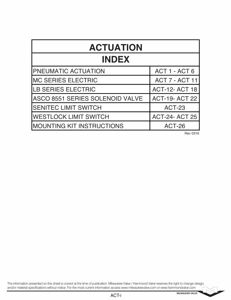
PNEUMATIC ACTUATION ACT 1 - ACT 6MC SERIES ELECTRIC ACT 7 - ACT 11LB SERIES ELECTRIC ACT-12- ACT 18ASCO 8551 SERIES SOLENOID VALVE ACT-19- ACT 22
32-TCAHCTIWS TIMIL CETINESWESTLOCK LIMIT SWITCH ACT-24- ACT 25MOUNTING KIT INSTRUCTIONS ACT-26
ACTUATIONINDEX
MILWAUKEE VALVEACT-i
The information presented on this sheet is correct at the time of publication. Milwaukee Valve / Hammond Valve reserves the right to change design,and/or material specifications without notice. For the most current information access www.milwaukeevalve.com or www.hammondvalve.com
Rev 0316

MILWAUKEE VALVEACT-1
The information presented on this sheet is correct at the time of publication. Milwaukee Valve / Hammond Valve reserves the right to change design,and/or material specifications without notice. For the most current information access www.milwaukeevalve.com or www.hammondvalve.com

ACT-2

VIEW
OF PA
RTS
Part List for Milwaukee Valve MC-Series Actuators Item # Qty. Part Name Material
* Material used for high temperature applications. ** Material used for low temperature applications.
ART
VIEW
OF P
PA
ARTS
.
1
1
117
165
143
121
Qty Item #
Part NamePart List for Milwaukee V
Body
Flange Bearing
clipIndicator
asherPinion Cir
Pinion W
Upper Pinion O-Ring
Left End Cap
.
Materialalve MC-Series Actuators
6005T5 Extruded Aluminum
Delrin/Polysulphone (PSU)*
Stainless SteelABS
Stainless Steel
em NBR/Viton*/Low T Temp NBR**
ASTM 384 Cast Aluminum
Part List for Milwaukee V
6005T5 Extruded Aluminum
Delrin/Polysulphone (PSU)*
Stainless SteelStainless Steel
emp NBR**
ASTM 384 Cast Aluminum
1
2
2
1
2
22
1817
81615
0-121413
21211
2109
187
Indicator Screw
Piston O-Ring
End Cap O-Ring
Right End Cap
Piston Skate
Stop NutStop O-Ring
End Cap Socket Head Cap Screw
Spring Cartridge0-12
Piston Guide
Piston
Indicator
ABS
em
em
ASTM 384 Cast Aluminum
Delrin/Polysulphone (PSU)*
Stainless Steelemp NBR**NBR/Viton*/Low T
Stainless SteelEnd Cap Socket Head Cap Screw
Epoxy Coated Spring Steel
Bronze Impregnated PTFENBR/Viton*/Low T Temp NBR**
ASTM A23320 AnodizedNBR/Viton*/Low T Temp NBR**
ABS
emp NBR**
emp NBR**
ASTM 384 Cast Aluminum
Delrin/Polysulphone (PSU)*
Stainless Steelemp NBR**
Stainless Steel
Epoxy Coated Spring Steel
Bronze Impregnated PTFE
ASTM A23320 Anodized
2
1
1125
12423
12221
22019
Stop Nut
Air Channel Plug
Pinion Cam
Lower Pinion BearingLower Pinion O-Ring
Pinion
Thrust Bearing
Stop Bolt
emp NBR**
Electroless Nickel/Forged 1045 Carbon Steel
Delrin/Polysulphone (PSU)* emp NBR**TNBR/Viton*/Low
Electroless Nickel/Alloy Steel
Delrin/Polysulphone (PSU)*
Stainless SteelNBR/Viton*/Low T
emp NBR**
Electroless Nickel/Forged 1045 Carbon Steel
Delrin/Polysulphone (PSU)* emp NBR**
Electroless Nickel/Alloy Steel
Delrin/Polysulphone (PSU)*
Stainless Steel
ACT-3

Double Acting Spring Return
Rev. 1
Model
40PSI
Double Acting
120100806040
40AIRSpringS#
ALL
AIR100
Spring Return
AIRAIR8060
AIR120
AIR100
MC20
241
170
MC34
MC1 57
96
Model
723
510
170
602482361241
287
425340255170
23919114396
14111385
140138
1677199S2
86
214S6115178S5
267692143S4619969107S3971224671S2
126S671105S5
11385784S432534363S353672942S2
End StartEndStartSpring
282525378406259287
153
1231983911430515822174137328194244110160352230267145183375265290181206
651051758167861203872182107134598619612814880100210149162101115
StartEndStartEndStart
617291
644498
160
367207327390242362413278398436314434459349
201113181215134203229155224244176245258197
EndStartEnd
544
MC105
MC75
369
241
MC48
1632
1107
13601088816544
723
922738553369
602482361241
319
70
319
224314468S4187303236351S3304381157234S2
213
470470S6S6266392S5
52152213314S4130206160235S3208259106157S2
296S6178246S5
4196142197S491132107148S3
1401677199S2
594
1031
594
60976233949311107268414565721189843919573650
383
2602604114117777229229647338464156282700417517234335753495571312388806573624391441
18126462145419231299111180454280335161216490329370210251525378406259287
625
1147
625
130187812641379995138114581112
420
776776442442703829521782883599860936678939989756
502301469538350518573399568609448617644498
MC237
1190
1658
MC157
787
3569
4974
2361
4145331624871658
2974237917841190
196815741181787
1060906
639
1221438752S21606S6
8831339S51194837071071S4386659530803S3654836353535S2
471
1006S6533838S5
109353426671S4276459320503S3444566213335S2
702S6393585S5
1309
37081914
25642879173520507731319178724
2090104014964469012267130816727131078244415761849981125426201844202612491431
874
5529191635291415720102533063615228881132498742162810551239666849173512231345833956
374605105336953492684222415
19624223
1331
4537339325081367
223026851635249828621903276530382171303332152438
913
1698942149918051110166719111277183420181445200221241612
114364410301222761
MC406
2035
3166
MC633
MC331
6104
94977914633247493166
5087406930522035
1737
2347
1313
3558S5303127218782847S41014174114082135S3172622109391423S2
2630S614472192S5
28187711581754S472011668681315S3
11581456579877S22255S6
10941879S51557838751503S453110026561128S3
2833
5526
3350
2741395111662377599634524421187728466465416448902589331669354876536033013785
1439233342213163640187726228601605392923162912129818944219275432011737218445083193349121752473
1061200423211743051143722226081393327018132441984161234892189266013601831
3474
5890
2719
71014315660275705027731380405739802585096450
43682456391246572895435149463333478952363772522755254210
36621890309538802266347140992642384743183018
MC1009
9158
6297
MC1260
5049
27475
18891
2289518316137379158
15148
157421259494456297
126241009975745049
3334
5553
2817
496641455777S3109035260634827633851S2
4039
7769S646286475S5
1117259537025180S42412352027773885S33707444618512590S2
6308S633665257S5
844235726924206S41895303020193154S32947370313462103S2
4270S623473558S5
5057
10189
18633124451407778909522200141437115459981510903
8585
482470401676389211114611979662971481812040741488924266574312966870998175561666913891100041074368567594
37906060126635359258484267332317420999315893740633684882106046945808044205555112777996875354716228
20293482454190755262741395111662377
21556
11121
5178
2318817000234822457018926
8840
13337797312416142639268137111518810563150061611411858163011704013152
11110631598911178373661094312456841811994131299469130451380210521
66313604589071014315
MC1831
MC2928
14641
4392336603292822196214641
8289
1130616055S611334942213379S51321931346300753710703S4151035810818456538027S31698784861006937695352S2
11554S669089628S5
1408358555267703S43334496641455777S3
23287
14488
116201636847019450251711429618253737711334270561697120137100531321928940196472202212729151033082522323239061540416987
666899322113537715870859411314403867591725110519126965964814018633124451407778909522
15779
254573020618539281333209021214308093397423890334853585926566361603774329242
1904311224177052042513149196302180715075215562318817000
ACT-4

SIZE L W1 W2 H1 H2 P BC1 T1 BC2 T2 A B C D E F
Rev. 1
W1LSIZE
PH2H1W2W1
BC2T1BC1
CBAT2
FEDC
3.15
3.90
4.72
5.87
6.24
6.08
15.51MC406
15.04MC331
5.16
12.28MC237
10.67MC157
4.43
10.43MC105
8.35MC75
3.50
7.32MC48
6.69MC34
3.11
5.79MC20
4.91MC1
0.79 (20mm)
0.79 (20mm)
0.79 (20mm)
1.18 (30mm)
1.18 (30mm)
1.18 (30mm)
6.817.995.986.24
6.507.685.756.08
0.79 (20mm)
6.147.325.615.87
5.286.064.785.16
0.79 (20mm)
4.595.384.274.72
4.295.084.064.43
0.79 (20mm)
3.934.713.743.90
3.464.243.303.50
0.79 (20mm)
2.833.622.803.15
2.383.172.383.11
1.969 (F05)*
2.756 (F07)
2.756 (F07)
4.016 (F10)
4.921 (F12)
4.921 (F12)
3/8-16 UNC4.016 (F10)1.18 (30mm)
3/8-16 UNC4.016 (F10)1.18 (30mm)
4.016 (F10)
5/16-18 UNC2.756 (F07)1.18 (30mm)
5/16-18 UNC2.756 (F07)0.79 (20mm)
2.756 (F07)
1/4-20 UNC1.969 (F05)0.79 (20mm)
1/4-20 UNC1.969 (F05)0.79 (20mm)
2.756 (F07)
1/4-20 UNC1.969 (F05)0.79 (20mm)
1/4-20 UNC1.969 (F05)0.79 (20mm)
1.969 (F05)
#10-32 UNF*1.417 (F03)*0.79 (20mm)
#10-32 UNF1.417 (F03)0.79 (20mm)
0.59
0.71
0.93
1.10
1.42
1.30
6.363.15/5.12**1/2-13 UNC4.921 (F12)
6.103.15/5.12**1/2-13 UNC4.921 (F12)
1.22
5.753.15/5.12**3/8-16 UNC4.016 (F10)
4.843.153/8-16 UNC4.016 (F10)
0.94
4.373.155/16-18 UNC2.756 (F07)
3.883.155/16-18 UNC2.756 (F07)
0.71
3.703.155/16-18 UNC2.756 (F07)
3.193.155/16-18 UNC2.756 (F07)
0.55
-3.151/4-20 UNC*1.969 (F05)*
-3.151/4-20 UNC1.969 (F05)
0.433 (11mm)
0.551 (14mm)
0.669 (17mm)
0.866 (22mm)
1.063 (27mm)
0.866 (22mm)
3.034.721.42
2.954.331.30
0.866 (22mm)
2.933.941.10
2.523.621.22
0.669 (17mm)
2.303.070.93
2.253.070.94
0.551 (14mm)
2.093.070.71
1.852.670.71
0.433 (11mm)
1.612.090.59
1.441.890.55
**Sizes 237-633 have 3.15 x 1.18 and a 5.12 x 1.18 top mounting with (8) M5 x 0.8 threaded holes.
8.78
11.42
12.48
*The size 20 is also available with an F04 (#10-32 UNF on a 1.654 B.C.) mounting pattern in place of the F03/F05.
29.13MC2928
9.70
25.28MC1831
21.50MC1260
7.26
20.87MC1009
18.11MC633
**Sizes 237-633 have 3.15 x 1.18 and a 5.12 x 1.18 top mounting with (8) M5 x 0.8 threaded holes.
1.18 (30mm)
1.18 (30mm)
1.18 (30mm)
*The size 20 is also available with an F04 (#10-32 UNF on a 1.654 B.C.) mounting pattern in place of the F03/F05.
12.9914.1711.5712.48
1.18 (30mm)
11.4612.6410.2411.42
10.0811.268.909.70
1.18 (30mm)
9.0910.288.118.78
7.808.986.857.26
**Sizes 237-633 have 3.15 x 1.18 and a 5.12 x 1.18 top mounting with (8) M5 x 0.8 threaded holes.
-
-
-
*The size 20 is also available with an F04 (#10-32 UNF on a 1.654 B.C.) mounting pattern in place of the F03/F05.
3/4-10 UNC6.496 (F16)1.18 (30mm)
-
3/4-10 UNC6.496 (F16)1.18 (30mm)
5/8-11 UNC5.512 (F14)1.18 (30mm)
4.921 (F12)
5/8-11 UNC5.512 (F14)1.18 (30mm)
3/8-16 UNC4.016 (F10)1.18 (30mm)
1.65
2.24
2.2411.855.12-
1.65
10.455.12-
9.295.12-
1.46
8.525.12-
7.263.15/5.12**1/2-13 UNC4.921 (F12)
1.417 (36mm)
1.811 (46mm)
1.811 (46mm)5.796.302.24
1.417 (36mm)
5.126.302.24
4.455.121.65
1.063 (27mm)
4.065.121.65
3.434.721.46
ACT-5
TEM
P
SP
EED
AIR
VO
LUM
E
WEIG
HT
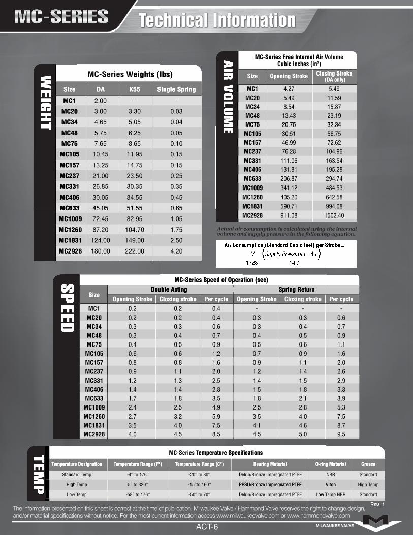
Size DA K55 Single Spring
Size Opening Stroke Closing Stroke (DA only)
Size
Opening Stroke Closing stroke Per cycle Opening Stroke Closing stroke Per cycle
Temperature Designation Temperature Range (F°) Temperature Range (C°) Bearing Material O-ring Material Grease
Rev. 1
Size
MC20
MC34
MC1
-
eights (lbs)
5.05
3.30
Single Spring
4.65MC34
3.00MC20
2.00
K55DA
MC-Series W
-
eights (lbs)
0.04
0.03
Single Spring
4.27
)
8.54
20.7513.43
(
MC75MC48
5.49MC34MC20MC1
Size Opening Stroke Closing StrokeOpening Stroke
Size
3Cubic Inches (inMC-Series Free Internal Air V
5.49
olume
15.87
32.3423.19
(DA only)
11.59
Closing Stroke
MC-Series Free Internal Air V
MC406
MC633
MC331
MC157
MC75
MC237
MC105
MC48
8.65
14.75
30.35
51.55
34.55
45.05MC633
30.05MC406
23.50
26.85MC331
21.00MC237
11.95
13.25MC157
10.45MC105
6.25
7.65MC75
5.75MC48
MC1831MC1260
0.10
0.15
0.35
0.65
0.45
0.25
0.15
0.05
MC1009
20.75
46.99
111.06
206.87
405.20590.71MC1831
341.12MC1260MC1009
131.81MC633MC406
76.28MC331MC237
30.51MC157MC105MC75
32.34
72.62
163.54
294.74
642.58994.08
484.53
195.28
104.96
56.75
MC1831
MC2928
MC1260
MC633
MC1009
Double Acting
51.55
104.70
222.00
149.00
180.00MC2928
124.00MC1831
82.95
87.20MC1260
72.45MC1009
45.05MC633
MC-Series Speed of Operation (sec)
MC29280.65
1.75
4.20
2.50
1.05
Double Acting
Spring Return
MC-Series Speed of Operation (sec)
1502.40911.08MC2928
1502.40
0.90.8
0.4
0.3
Size
0.2
Closing stroke
MC237
0.6MC157MC105
0.3MC75MC48
0.2MC34MC20MC1
Opening Stroke
0.4
0.6
0.9
1.62.0
Opening Stroke
1.1
1.20.80.6
0.70.50.4
0.40.30.2
Double Acting
0.2
Per cycleClosing stroke
-
0.4
0.6
1.11.4
Closing stroke
1.2
0.90.90.7
0.50.50.4
0.30.30.3
Spring Return
-
Opening Stroke
-
0.7
1.1
2.02.6
Per cycle
1.6
0.9
0.6
3.54.0
2.7
1.7
1.2
MC2928MC1831
2.4MC1260MC1009
1.4MC633MC406MC331
emperature Specifications
2.5
3.5
5.9
8.57.5
4.54.0
4.93.22.5
2.81.81.41.3
MC-Series T
emperature Specifications
1.5
2.1
4.0
5.04.6
4.54.1
2.83.52.5
1.81.81.51.4
2.9
3.9
7.5
9.58.7
5.3
3.3
tandard T
Low T
High T
emperature
S
TTemperature Designation
-58° to 176°
-4° to 176°
5° to 320°
emperature Range (F°)
emp T Temp
empHigh T
emptandard T
Temperature Designation
Delrin/Bronze Impregnated PTFE
Delrin/Bronze Impregnated PTFE
PPSU/Bronze Impregnated PTFE
emperature Range (C°)
-50° to 70°
-15°to 160°
-20° to 80°
Temperature Range (F°)
Low T
Delrin/Bronze Impregnated PTFE
Viton
O-ring Material
Delrin/Bronze Impregnated PTFE
PPSU/Bronze Impregnated PTFE
Bearing Material
Standard
Standard
emp
Grease
emp NBRLow T
High TViton
NBR
O-ring Material
MILWAUKEE VALVEACT-6
The information presented on this sheet is correct at the time of publication. Milwaukee Valve / Hammond Valve reserves the right to change design,and/or material specifications without notice. For the most current information access www.milwaukeevalve.com or www.hammondvalve.com
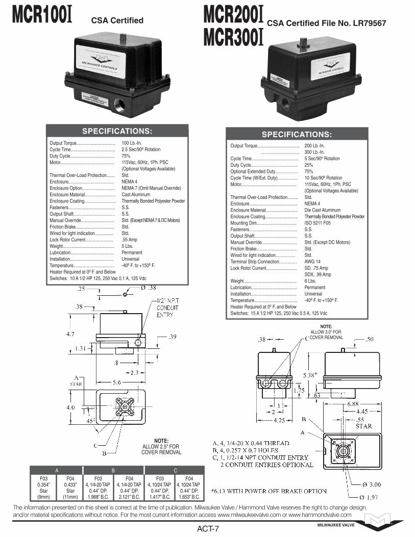
CSA Certified
Output Torque.................................Cycle Time......................................Duty Cycle......................................Motor..............................................
Thermal Over-Load Protection.......Enclosure.......................................Enclosure Option............................Enclosure Material..........................Enclosure Coating...........................Fasteners........................................Output Shaft...................................Manual Override.............................Friction Brake.................................Wired for light indication................ Lock Rotor Current........................Weight............................................Lubrication.....................................Installation.....................................Temperature...................................Heater Required at 0º F. and BelowSwitches: 10 A 1/2 HP 125, 250 Vac 0.1 A, 125 Vdc
100 Lb.-In.2.5 Sec/90º Rotation75%115Vac, 60Hz, 1Ph. PSC(Optional Voltages Available)Std.NEMA 4NEMA 7 (Omit Manual Override)Cast AluminumThermally Bonded Polyester PowderS.S.S.S.Std. (Except NEMA 7 & DC Motors)Std.Std..55 Amp5 Lbs.PermanentUniversal-40º F. to +150º F.
SPECIFICATIONS:
S
F030.354”Star
(9mm)
F040.433”Star
(11mm)
F034, 1/4-20 TAP
0.44” DP.1.968” B.C.
F044, 1/4-20 TAP
0.44” DP.2.121” B.C.
F034, 10/24 TAP
0.44” DP.1.417” B.C.
F044, 10/24 TAP
0.44” DP.1.653” B.C.
A B C
NOTE:ALLOW 2.5” FOR COVER REMOVAL
7K............................ 12K.......................... 14K.......................... 27K..........................C
SPECIFICATIONS:Output Torque.....................................................................
Cycle Time........................................Duty Cycle........................................Optional Extended Duty....................Cycle Time (W/Ext. Duty).................Motor...............................................
Thermal Over-Load Protection.........Enclosure.........................................Enclosure Material...........................Enclosure Coating............................Mounting Dim..................................Fasteners.........................................Output Shaft....................................Manual Override..............................Friction Brake..................................Wired for light indication.................Terminal Strip Connection............... Lock Rotor Current..........................
Weight.............................................Lubrication.......................................Installation.......................................Temperature.....................................Heater Required at 0º F. and BelowSwitches: 15 A 1/2 HP 125, 250 Vac 0.5 A, 125 Vdc
200 Lb.-In.300 Lb.-In.5 Sec/90º Rotation25%75%10 Sec/90º Rotation115Vac, 60Hz, 1Ph. PSC(Optional Voltages Available)Std.NEMA 4Die Cast AluminumThermally Bonded Polyester PowderISO 5211 F05S.S.S.S.Std. (Except DC Motors)Std.Std.AWG 14SD, .75 AmpSDX, .99 Amp6 Lbs.PermanentUniversal-40º F. to +150º F.
SPECIFICATIONS:
NOTE:ALLOW 3.0” FOR COVER REMOVAL
7K............................ 12K.......................... 14K.......................... 27K..........................C
CSA Certified File No. LR79567C
7K............................ 12K.......................... 14K.......................... 27K..........................C
MCR200IMCR300I
MCR100I
MILWAUKEE VALVEACT-7
The information presented on this sheet is correct at the time of publication. Milwaukee Valve / Hammond Valve reserves the right to change design,and/or material specifications without notice. For the most current information access www.milwaukeevalve.com or www.hammondvalve.com

MILWAUKEE VALVEACT-8
The information presented on this sheet is correct at the time of publication. Milwaukee Valve / Hammond Valve reserves the right to change design,and/or material specifications without notice. For the most current information access www.milwaukeevalve.com or www.hammondvalve.com
LX............................C LX............................D
................................. ................................. .................................C .................................. ..................................D
............................W
CSA Certified File No. LR79567 Class I Groups C & Class II Groups E, F &
G Div. I & II
..................................C
.................................C
LX............................C LX............................D
................................. ................................. .................................C .................................. ..................................D
............................W
SPECIFICATIONS:Output Torque ................................. .................................Cycle Time.......................................Duty Cycle.......................................Optional Extended Duty...................Cycle Time (W/Ext. Duty).................Motor...............................................
Thermal Over-Load Protection.........Enclosure.........................................Enclosure Material...........................Enclosure Coating............................Mounting Dim..................................Fasteners.........................................Output Shaft....................................Manual Override..............................Friction Brake..................................Wired for light indication.................Terminal Strip Connection............... Lock Rotor Current..........................
Weight.............................................Lubrication......................................Installation.......................................Temperature.....................................Heater Required at 0º F. and BelowSwitches: 15 A 1/2 HP 125, 250 Vac 0.5 A, 125 Vdc
200 Lb.-In.300 Lb.-In.5 Sec/90º Rotation25%75%10 Sec/90º Rotation115Vac, 60Hz, 1Ph. PSC(Optional Voltages Available)Std.NEMA 7Cast AluminumThermally Bonded Polyester PowderISO 5211 F05S.S.S.S.OptionalStd.Std.AWG 14SR, .75 AmpSX, .99 Amp15 Lbs.PermanentUniversal-40º F. to +140º F.
SPECIFICATIONS:
S
NOTE:ALLOW 4.0” FOR COVER REMOVAL
LX............................C LX............................D
................................. ................................. .................................C .................................. ..................................D
............................W
Select This Enclosure When Positioner, Timer, Brake or Speed Control is Required C
..................................C
.................................C
LX............................C LX............................D
................................. ................................. .................................C .................................. ..................................D
............................W
SPECIFICATIONS:Output Torque.................................. ..................................Cycle Time.......................................Duty Cycle.......................................Optional Extended Duty...................Cycle Time (W/Ext. Duty).................Motor...............................................
Thermal Over-Load Protection.........Enclosure.........................................Enclosure Material...........................Enclosure Coating............................Mounting Dim..................................Fasteners.........................................Output Shaft....................................Manual Override..............................Friction Brake..................................Wired for light indication.................Terminal Strip Connection............... Lock Rotor Current..........................
Weight.............................................Lubrication......................................Installation.......................................Temperature.....................................Heater Required at 0º F. and Below Switches: 15 A 1/2 HP 125, 250 Vac 0.5 A, 125 Vdc
200 Lb.-In.300 Lb.-In.5 Sec/90º Rotation25%75%10 Sec/90º Rotation115Vac, 60Hz, 1Ph. PSC(Optional Voltages Available)Std.NEMA 4Cast AluminumThermally Bonded Polyester PowderISO 5211 F05S.S.S.S.Not AvailableStd.Std.AWG 14SR, .75 AmpSX, .99 Amp8 Lbs.PermanentUniversal-40º F. to +150º F.
.................................C
NOTE:ALLOW 3.0” FOR COVER REMOVAL
6
MCRB200I/MCRB300I MCR W/NEMA 4/7

MILWAUKEE VALVEACT-9
The information presented on this sheet is correct at the time of publication. Milwaukee Valve / Hammond Valve reserves the right to change design,and/or material specifications without notice. For the most current information access www.milwaukeevalve.com or www.hammondvalve.com
LX............................C LX............................D
SPECIFICATIONS:Output Torque................................. ................................. ................................. .................................Cycle Time....................................... .................................. ..................................Duty Cycle.......................................Motor...............................................
Thermal Over-Load Protection.........Enclosure.........................................Enclosure Option.............................Enclosure Material...........................Mounting Dim..................................Enclosure Coating............................Fasteners.........................................Output Shaft....................................Manual Override..............................Friction Brake..................................Wired for light indication.................Terminal Strip Connection............... Lock Rotor Current.......................... ............................Weight..............................................Lubrication......................................Installation.......................................Temperature.....................................Heater Required at 0º F. and BelowSwitches: 15 A 1/2 HP 125, 250 Vac 0.5 A, 125 Vdc
400 Lb.-In.675 Lb.-In.1000 Lb.-In.1500 Lb.-In.10 Sec/90º Rotation15 Sec/90º Rotation30 Sec/90º Rotation25%115Vac, 60Hz, 1Ph. PSC(Optional Voltages Available)Std.NEMA 4NEMA 7Cast AluminumISO 5211 F07Thermally Bonded Polyester PowderS.S.S.S.Std. NEMA 4, Opt. NEMA 7Std.Std.AWG 14.75 Amp1.1 Amps13 Lbs. NEMA 4, 16 Lbs. NEMA 7 PermanentUniversal-40º F. to +150º F.
D
..................................C
.................................C
LX............................C LX............................D
................................. ................................. .................................C .................................. ..................................D
............................W
Dimensions in inches
A
B
C
D
Enclosure
8.57.0
2.38 3.13
2.812.81
2.63 3.38
NEMA 4 NEMA 7
NOTE:ALLOW 4.0” FOR COVER REMOVAL
..................................C
67
CSA Certified
LX............................C LX............................D
................................. ................................. .................................C .................................. ..................................D
..................................C
.................................C
MCR400I, MCR675I,MCR1000I, MCR1500I,MCRB400I, MCRB675I,MCRB1000I, MCRB1500I
NOTE: MCRB - Includes Motor Brake

All units are supplied with two limit switches for electrically controlling open and close positions; a mechanical stop is set at the factory for positioning the designated fail position. The designated fail position is available in both open (CCW rotation) or close (CW rotation) position. Spring return actuators are not intended to be used in control applications.
200 Lb.-In.10 Sec/90º Rotation3 Sec/90º Rotation25%115 Vac, 60 Hz, 1 Ph. PSC Or220 Vac, 60 Hz, 1Ph.Std.NEMA 4NEMA 7Cast AluminumThermally Bonded Polyester Powder S.S.S.S.AWG 14.75 Amps13 Lbs.PermanentISO 5211 F07Universal0º F. to +150º F.
Output Torque ..................................Cycle Time.....Power Stroke............. Spring Stroke.............Duty Cycle........................................Motor...............................................
Thermal Over-Load Protection.........Enclosure ........................................Enclosure Option..............................Enclosure Material...........................Enclosure Coating............................Fasteners.........................................Output Shaft.....................................Terminal Strip Connection............... Lock Rotor Current..........................Weight.............................................Lubrication.......................................Mounting.........................................Installation.......................................Temperature.....................................Heater Required at 32º F. and BelowSwitches: 15 A 1/2 HP 125, 250 Vac 0.5 A, 125 Vdc
SPECIFICATIONS:
E
NOTE:ALLOW 4.0” FOR COVER REMOVAL
NOTE:Equipped with Power on Brake
Torque (Lb.-In.)
Cycle Time Sec./90º Rotation
Lock Rotor Current
Spring Start
Spring End
Power Stroke
Power Stroke
Spring Start
600 800
400
400
600
600
12 Sec 12 Sec
3 Sec 3 Sec
2.0 Amp 2.0 Amp
SPECIFICATIONS:
S
Electric Spring Return Wiring Diagram:
NOTE:ALLOW 6.0” FOR COVER REMOVAL
MCSRE400MCSRE600
MCSRE200
MILWAUKEE VALVEACT-10
The information presented on this sheet is correct at the time of publication. Milwaukee Valve / Hammond Valve reserves the right to change design,and/or material specifications without notice. For the most current information access www.milwaukeevalve.com or www.hammondvalve.com

MILWAUKEE VALVEACT-11
The information presented on this sheet is correct at the time of publication. Milwaukee Valve / Hammond Valve reserves the right to change design,and/or material specifications without notice. For the most current information access www.milwaukeevalve.com or www.hammondvalve.com
Typical Wiring Diagram
S
Spr
ACTUATOR WIRING
MC SERIES ELECTRIC ACTUATORS: OPTIONS VOLTAGES: 120 VAC, 220 VAC 1 PH, 24 VAC, 24VDC, 12 VDC
AUX. SWITCHES: 1 SWITCH, 2 SWITCHES MOTOR BRAKE: REQUIRED FOR BUTTERFLY VALVES
1 K POT VALVE POSITIONER: 4-20 MADC OR 0-10 VDC HEATER THERMOSTAT SPEED CONTROL EXTENDED DUTY MOTORS
TIMER THREE POSITION DIAL POSITION INDICATON 4-20 MADC TRANSMITTER REMOTE ON AND OFF AND LOCAL TWO WIRE RELAY TORQUE SWITCHES SPECIAL MOUNTING MALE OR ISO HOUSING, NEMA 4/4X AND NEMA 7
Typical Wiring DiagramWith Two Auxiliary Switches
S
Spr

Type Torque Operating Flangein-lbs time s/90° ISO
OA3 310 5 F05 / 07
OA8 885 5 - 25 - 50 F05 / 07OA15 1350 15 - 25 F07
QUARTER-TURNELECTRIC ACTUATORTYPE OA
DESCRIPTION:
Type OA Quarter-turn actuators offer a verycompact waterproof body with the same sturdyfeatures of larger industrial actuators:
largely dimensioned worm and quadrant outputgear (naturally self locking), ease of adjustment,precise and vibration proof end of trazvel system,heavy duty motors with internal thermalprotection, emergency manual handwheel,easy to read position indicator, ISO flange andremovable socket permits direct or indirectmounting on any type of quarter-turn valve.
SPECIFICATIONS:
Quarter-turn, watertight body to NEMA 4, 4X & 6,proportional position indicator, self locking gear,S4-30% duty rating motor, class F insulated, 2 endof travel switches adjustable over the entire travel,anti-condensation heater, 2 adjustable mechanicalstops, thermal protection, emergency handwheelmounted on the final reduction stage, 2 conduitentries, combined with F05/F07 ISO flange.
OPTIONS:
- 2 auxillary limit switches (free contacts)
- Position sensor by potentiometer 1000 Ω
- Position transmitter 4-20 mA, type TAM
- INTEGRAL+ local control
- MiniGRAL+ remote control
- MiniGAM+ or PosiGAM+ modulating control
TECHNICAL DATA
MILWAUKEE VALVEACT-12
The information presented on this sheet is correct at the time of publication. Milwaukee Valve / Hammond Valve reserves the right to change design,and/or material specifications without notice. For the most current information access www.milwaukeevalve.com or www.hammondvalve.com
Rev 0313

MILWAUKEE VALVEACT-13
The information presented on this sheet is correct at the time of publication. Milwaukee Valve / Hammond Valve reserves the right to change design,and/or material specifications without notice. For the most current information access www.milwaukeevalve.com or www.hammondvalve.com
Type A B C ØD Weight lbsOA3 9.88” 3.54” 6.31” Ø2.36” 12OA8 11.5” 3.54” 7.88” Ø2.36” 15OA15 14.63” 4.38” 10.24” Ø3.94” 17
DIMENSIONAL DRAWING:
Note: The OA15 drive socket has 4 engagement claws.
OA Series
Rev 0313

MILWAUKEE VALVEACT-14
The information presented on this sheet is correct at the time of publication. Milwaukee Valve / Hammond Valve reserves the right to change design,and/or material specifications without notice. For the most current information access www.milwaukeevalve.com or www.hammondvalve.com
Type Torque Operating Flangein-lbs time s/90° ISO
AT25 2,225 15 - 25 - 50 F07/10AT50 4,500 25 F10/07AT100 8,850 24 F12AT200 22,125 29-59 F16AT400 35,400 53 F16
QUARTER-TURN ELECTRICACTUATORTYPE AT
DESCRIPTION:
The AT range offers a selection of heavy dutycompact quarter turn actuators designed to operateall kinds of ball, butterfly valves, as well as largeindustrial dampers, maintenance free for many years:
largely dimensioned final worm and quadrant gearreduction (totaly self locking), easy to adjust,precise and vibration proof end of travel systemand torque limiting device, heavy duty single or 3phases motors protected by thermal overload,easy to operate manual handwheel, easy to readposition indicator, ISO flange and removablesocket permits direct or indirect mounting on anytype of quarter-turn valve.
SPECIFICATIONS:
Self-locking quarter-turn, watertight body to NEMA 4,4X & 6, proportional position indicator, S4-30% dutyrating motor, class F insulated, 2 end of travelswitches and 2 auxilliary limit switches (dry contacts)adjustable over the whole travel, 2 independentlyadjustable torque limit switches, anti-condensationheater, 2 adjustable mechanical stops, thermalprotection, emergency handwheel mounted on thefinal reduction stage, 2 conduit entries, ISO F07/F10combined flange.
OPTIONS:
Position sensor by potentiometer 1000 Ω
Position transmitter 4-20 mA
INTEGRAL+ control
MiniGAM+ or PosiGAM+ positioner
Special needs: ask us
TECHNICAL DATA
Rev 0313

MILWAUKEE VALVEACT-15
The information presented on this sheet is correct at the time of publication. Milwaukee Valve / Hammond Valve reserves the right to change design,and/or material specifications without notice. For the most current information access www.milwaukeevalve.com or www.hammondvalve.com
DIMENSIONAL DRAWING:
Note: AT50 sockets have 4 claws.
AT 25/50 Series
Rev 0313

DIMENSIONAL DRAWING:
MILWAUKEE VALVEACT-16
The information presented on this sheet is correct at the time of publication. Milwaukee Valve / Hammond Valve reserves the right to change design,and/or material specifications without notice. For the most current information access www.milwaukeevalve.com or www.hammondvalve.com
AT 100 Series
NET WEIGHT
AT 100 - 104 lbs
Handwheel clutch
3.54
4 "
1.575 "
*3
*3
Position indicator
Adjustable mechanical endstops 90° (+/- 2°)
Ø11.808 "
7.875 "
16.766 "
4.48
9 "
20.4
95 "
*1
ISO 5211F12
View A of the flange
Ron
delle
de
cent
rage
Cen
terin
g rin
g
13.393 "
17.387 "
0.118 "
Ø3.
347
"f8
F12 = 8 x M12Prof./Depth: 0.709"
Ø5.
906
"
Ø4.
922
"
45°
90°
DIMENSIONAL DRAWING:
MILWAUKEE VALVEACT-17
The information presented on this sheet is correct at the time of publication. Milwaukee Valve / Hammond Valve reserves the right to change design,and/or material specifications without notice. For the most current information access www.milwaukeevalve.com or www.hammondvalve.com
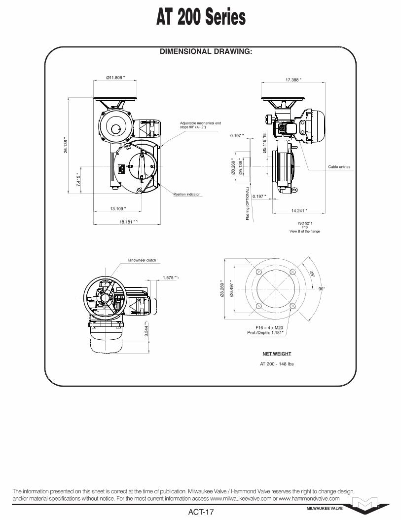
AT 200 Series
NET WEIGHT
AT 200 - 148 lbs
Handwheel clutch
3.54
4 "
1.575 "
*3
*3
Position indicator
Adjustable mechanical endstops 90° (+/- 2°)
Ø11.808 "
13.109 "
18.181 "
7.41
5 "
26.1
38 "
*1
ISO 5211F16
View B of the flange
Flat
ring
(OP
TIO
NA
L)
Cable entries
14.241 "
0.197 "
Ø5.
119
"f8
0.197 "
Ø8.
269
"
Ø5.
138
"
17.388 "
F16 = 4 x M20Prof./Depth: 1.181"
Ø8.
269
"
Ø6.
497
"
45°
90°

DIMENSIONAL DRAWING:
MILWAUKEE VALVEACT-18
The information presented on this sheet is correct at the time of publication. Milwaukee Valve / Hammond Valve reserves the right to change design,and/or material specifications without notice. For the most current information access www.milwaukeevalve.com or www.hammondvalve.com
AT 400 Series
NET WEIGHT
AT 400 - 148 lbs
Handwheel clutch
3.54
3 "
1.575 "
*3*3
Position indicator
Adjustable mechanical endstops 90° (+/- 2°)
Ø11.807 "
11.331 "
18.179 "
*1
Cable entries
Emergency Handwheel
Ø5.
118
"f8
0.197 "
14.239 "
17.386 "
26.1
37 "
6.07
7 "
F16 = 4 x M20Prof./Depth: 1.181"
ISO 5211F16
View A of the flange
Ø8.
269
"
Ø6.
497
"
45°
90°

MILWAUKEE VALVEACT-19
The information presented on this sheet is correct at the time of publication. Milwaukee Valve / Hammond Valve reserves the right to change design,and/or material specifications without notice. For the most current information access www.milwaukeevalve.com or www.hammondvalve.com
3/2 • 5/2SERIES8551
Direct Mount
Solenoid Enclosures
Approvals:SC, WT: UL recognized component, CSA certified.EF: UL and CSA solenoid approval. Meets applicable CEdirectives. Refer to Engineering Section for details.
Construction
Electrical
Nominal Ambient Temperature Ranges:SC: AC/DC: 5˚F to +140˚F (-15˚C to 60˚C)
EF: AC: 5˚F to +104˚F (-15˚C to 40˚C)DC: 5˚F to +77˚F (-15˚C to 25˚C)
WT: AC: 5˚F to +104˚F (-15˚C to 60˚C)DC: 5˚F to +77˚F (-15˚C to 25˚C)
Note: For temperatures below 32˚F (0˚C) moisture-free airmust be used. Refer to Engineering Section for details.
4qwer
Pilot Operated
Direct Mount High Flow ValvesAnodized Aluminum Bodies
Direct NAMUR Mount • 1/4" NPT
Valve Parts in Contact with Fluid Body Black Anodized Aluminum Spring Phosphate treated black steel Shading Coil Copper Seals NBR + PUR Core and Core tube Stainless Steel / Brass End Covers and Plate 6/6 glass filled PA/FV Spool Aluminum Internal Parts Zamak, Steel, CA
Features
• Compact spool valve convertible from 3/2 to 5/2.
• NAMUR Mount construction.
• Standard manual operator.
• DIN, Watertight and Explosionproof solenoids available.
• Single and dual solenoid constructions.
• Mountable in any position.
Standard: - PrefixSC = IP65 type DIN (open frame) per 46244WT= Combination General Purpose and Watertight Types 1, 2, 3, 3S, 4, and 4X EF = Combination Explosionproof and Watertight Types 3, 3S, 4, 4X, 6, 6P, 7, 9
CLASS 1, DIV. 1 (Groups A - D) and CLASS 1, DIV.2 Type 9 (Groups E-G)
Optional:CENELEC (EEx d,m,em, and i)Low Power, Intrinsically Safe, and Red-Hat II versions. Consult factory for details.
Option:Metering-Specify suffix “M” when ordering. i.e.: SC8551A001MMS
Standard Coiland Class of
InsulationEnclosure
Type
Watt Rating and Power Consumption
Spare Coil Part Number
DCWatts
ACWatts
VA Holding
VAInrush AC DC
F SC 3 2.5 3.5 6 400125 400125
F EF 6.9 6.3 7 10.1 266762 270007
F WT 6.9 6.3 7 10.1 266763 270008 Standard Voltages: SC: 24, 120, 240 volts AC, 50-60 Hz; 12, 24, 120 volts DC. WT and EF: 24/50-60Hz, (120/60, 110-120/50) , (240/60, 220-240/50) volts AC; 6, 12, 24, 120 volts DC. Notes: Order as 120/60, 110/50 Order as 240/60, 220/50
3/2 5/2
122 4 10
531
122 4 14
531
122 4
531
122 4
531
%
^
)

MILWAUKEE VALVEACT-20
The information presented on this sheet is correct at the time of publication. Milwaukee Valve / Hammond Valve reserves the right to change design,and/or material specifications without notice. For the most current information access www.milwaukeevalve.com or www.hammondvalve.com
Specifications (Metric units)
Specifications (English units)
4
Dimensions: inches (mm)
Constr. Ref. 1
SERIES8551Direct Mount
Pipe Size (ins.)
Orifice Size (mm)
KvFlow
Factor(m3/h)
Pilot Pressure
(bars)
Fluid Temperature ˚C
(for single and dual solenoid) Single Solenoid Dual Solenoid
Watt Rating/Class of CoilInsulation
Minimum Maximum MinimumMaximum
ACMaximum
DC Catalog NumberConstr.Ref. No. Catalog Number
Constr.Ref. No. AC DC
OPEN FRAME DIN COIL
1/4 6.4 .6 2 10 -15 60 60 SC8551A1MS 1 SC8551A2MS 3 2.5 3
WATERTIGHT ENCLOSURE
1/4 6.4 .6 2 10 -15 40 25 WT8551A1MS 2 WT8551A2MS 4 6.3 6.9
EXPLOSIONPROOF ENCLOSURE
1/4 6.4 .6 2 10 -15 40 25 EF8551A1MS 2 EF8551A2MS 4 6.3 6.9
Note: 1/8 inch NPT exhausts.
Pipe Size (ins.)
Orifice Size (ins.)
Cv FlowFactor
Pilot Pressure
Fluid Temperature ˚F
(for single and dual solenoid) Single Solenoid Dual Solenoid
Watt Rating/ Class of CoilInsulation
Minimum Maximum MinimumMaximum
ACMaximum
DC Catalog NumberConstr. Ref. No. Catalog Number
Constr. Ref. No. AC DC
OPEN FRAME DIN COIL
1/4 1/4 .7 30 150 5 140 140 SC8551A1MS 1 SC8551A2MS 3 2.5 3
WATERTIGHT ENCLOSURE
1/4 1/4 .7 30 150 5 104 77 WT8551A1MS 2 WT8551A2MS 4 6.3 6.9
EXPLOSIONPROOF ENCLOSURE
1/4 1/4 .7 30 150 5 104 77 EF8551A1MS 2 EF8551A2MS 4 6.3 6.9
Note: 1/8 inch NPT exhausts.
Shown with Metering Option

MILWAUKEE VALVEACT-21
The information presented on this sheet is correct at the time of publication. Milwaukee Valve / Hammond Valve reserves the right to change design,and/or material specifications without notice. For the most current information access www.milwaukeevalve.com or www.hammondvalve.com
4Dimensions: inches (mm)
Constr. Ref. 2
SERIES8551Direct Mount
Constr. Ref. 3
Shown with Metering Option
Shown with Metering Option

MILWAUKEE VALVEACT-22
The information presented on this sheet is correct at the time of publication. Milwaukee Valve / Hammond Valve reserves the right to change design,and/or material specifications without notice. For the most current information access www.milwaukeevalve.com or www.hammondvalve.com
4Dimensions: inches (mm)
Constr. Ref. 4
SERIES8551Direct Mount
Shown with Metering Option

MILWAUKEE VALVEACT-23
The information presented on this sheet is correct at the time of publication. Milwaukee Valve / Hammond Valve reserves the right to change design,and/or material specifications without notice. For the most current information access www.milwaukeevalve.com or www.hammondvalve.com
Easy Wire TerminationSpace for the most difficult installations.
S
Introducing the “PrE2” Proximity SensorEncased is a Sentar housing and epoxy Ackralite hermetically sealed, the “PrE2”proximity sensor provides the industry’s foremost protection from moisture,shock and corrosive environments and electronic spikes that damage and short-en the life cycle capability of traditional PIDs. When accuracy, performance andreliability are critical, the Senitec “PrE2” provides the answer.
E
ENCLOSURE TYPEZ=ALUMINUMY=STAINLESS STEEL
CONDUITSA=STD 2 3/4" FEMALEB=3 3/4" FEMALEC=2 3/4" FEMALE, 1 1/2" MALE
BEARINGSB= STD BRONZES=STAINLESS STEEL
INDICATORA=STD 90 DEG BLACK/YELLOWB=90 DEG BLUE/WHITEC=90 DEG RED/WHITED=90 DEG GREEN/WHITEE=90 DEG RED/GREENF=90 DEG 3 WAYG=90 DEG 3 WAYH=90 DEG 3 WAYI=180 DEG 3 WAYJ=180 DEG 3 WAYK=90 DEG 4 WAYL=DEFINED BY USERN=NONE
SWITCH TYPEA=STD 10 AMP MECHANICALB=0.1 AMP GOLD MECHANICALC=3 AMP PROXIMITYD=1 AMP PROXIMITYE=2 AMP DPDT MECHANICALF=INDUCTIVEG=AS-I ®
NUMBER OF SWITCHES2=23=34=40=NONE
SHAFT1=303 SS NAMUR2=316 SS NAMUR3=303 SS 1/4 DD4=316 SS 1/4 DD
TERMINAL STRIP1=8 POLE FIXED2=8 POLE PLUG IN3=14 POLE FIXED4=14 POLE PLUG IN
MOUNTING1=80MM X 20MM NAMUR2=80MM X 30MM NAMUR3=130MM X 30MM NAMUR4=130MM X 20MM NAMUR5=2.25 SQ W (4) 5/16 - 18
SOLENOID0=NONE1=3 WAY 24VDC 0.2 AMP2=4 WAY 24VDC 0.2 AMP
Z A B A A 2 1 1 5 0
ENCL
OSUR
E TY
PE
COND
UITS
BEAR
INGS
INDI
CATO
R
SWIT
CH T
YPE
NO. O
F SW
ITCH
ES
SHAF
T
TERM
INAL
STR
IP
MOU
NTIN
G
SOLE
NOID
NEMA 7NEMA 7Part Numbering Chart
CL 1 II Gr ABCDEFG, Div. I II
NEMA 7NEMA 4
No Other Limit Switch Has This Much Experience With Valve Position and Control Indication.
SwitchesAll switch configurations, mechanical, inductive, SPDT,
DPDT, SPDT hermetically sealed proximity sensors,solenoid valves and analog feedback. Mechanical
Switches 10 amp SPDT as standard, enclosed on a PCBboard with no exposed wiring. Also available are .100 ampand gold plated SPDT switches for low power and intrinsi-
cally safe applications.
Easy “Set and Forget” Cam DesignThis patented setting system uses no mechanical devices (springs or screws) foradjustment. Senitec utilizes a unique internal leaf spring design, which preciselypositions and LOCKS on to a splined shaft, which prevents calibration and life cycleinaccuracies. When needed, the cam system is easily adjusted using no tools.
E
ENCLOSURE TYPEA=EASTAR ® (SS INSERTS)B=ALUMINUMC=STAINLESS STEEL
CONDUITSA=STD 2 1/2" FEMALEB=3 1/2" FEMALEC=2 1/2" FEMALE, 1 1/2" MALE
BEARINGSE=STD EASTAR (R)B= BRONZES=STAINLESS STEEL
INDICATORA=STD 90 DEG BLACK/YELLOWB=90 DEG BLUE/WHITEC=90 DEG RED/WHITED=90 DEG GREEN/WHITEE=90 DEG RED/GREENF=90 DEG 3 WAYG=90 DEG 3 WAYH=90 DEG 3 WAYI=180 DEG 3 WAYJ=180 DEG 3 WAYK=90 DEG 4 WAYL=DEFINED BY USERN=NONE
SWITCH TYPEA=STD 10 AMP MECHANICALB=0.1 AMP GOLD MECHANICALC=3 AMP PROXIMITYD=1 AMP PROXIMITYE=2 AMP DPDT MECHANICALF=INDUCTIVEG=AS-I ®
NUMBER OF SWITCHES2=23=34=40=NONE
SHAFT1=303 SS NAMUR2=316 SS NAMUR3=303 SS 1/4 DD4=316 SS 1/4 DD
TERMINAL STRIP1=8 POLE FIXED2=8 POLE PLUG IN3=14 POLE FIXED4=14 POLE PLUG IN
MOUNTING1=80MM X 20MM NAMUR2=80MM X 30MM NAMUR3=130MM X 30MM NAMUR4=130MM X 20MM NAMUR5=2.25 SQ W (4) 5/16 - 186=80MM X 10MM NAMUR
SOLENOID0=NONE1=3 WAY 24VDC 0.2 AMP2=4 WAY 24VDC 0.2 AMP
A A E A A 2 1 1 1 0
ENCL
OSUR
E TY
PE
COND
UITS
BEAR
INGS
INDI
CATO
R
SWIT
CH T
YPE
NO. O
F SW
ITCH
ES
SHAF
T
TERM
INAL
STR
IP
MOU
NTIN
G
SOLE
NOID
NEMA 3,NEMA 3, 4,4, 4X4XPart Numbering Chart
E
AAEAA21110 Limit Switch
BULLETIN NO. AR-13.00
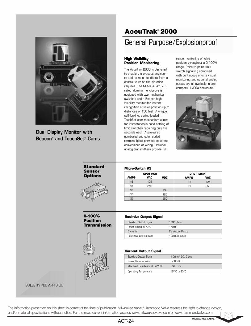
AccuTrak® 2000
General Purpose/Explosionproof
VDC
24
125
250
AMPS10
10
VAC125
250
VAC125
250
AMPS15
15
10
.50
.25
SPDT (V3) DPDT (Licon)
StandardSensorOptions
Micro-Switch V3
0-100%PositionTransmission
Resistive Output Signal1000 ohms
1 watt
Conductive Plastic
100,000 cycles
Standard Output Signal
Power Rating at 70°C
Elements
Rotational Life (no load)
Current Output Signal4-20 mA DC, 2 wire
5-38 VDC
950 ohms
-24°C to 85°C
Standard Output Signal
Power Requirements
Max. Load Resistance at 24 VDC
Operating Temperature
High Visibility Position Monitoring
The AccuTrak 2000 is designed to enable the process engineer to add as much feedback from a control valve as the situationrequires. The NEMA 4, 4x, 7, 9rated aluminum enclosure isequipped with two mechanicalswitches and a Beacon high visibility monitor for instant recognition of valve position up todistances of 150 feet. A uniqueself-locking, spring-loadedTouchSet cam mechanism allowsfor instantaneous hand setting oflimit switches requiring only fiveseconds each. A pre-wired numbered and color coded terminal block provides ease andconvenience of wiring. Optionalanalog transmitters provide full
range monitoring of valve position throughout a 0-100%range. Point to point limitswitch signalling combined with continuous on-site visual monitoring and optional analogoutput are all available in onecompact UL/CSA enclosure.
Dual Display Monitor withBeacon® and TouchSet® Cams
MILWAUKEE VALVEACT-24
The information presented on this sheet is correct at the time of publication. Milwaukee Valve / Hammond Valve reserves the right to change design,and/or material specifications without notice. For the most current information access www.milwaukeevalve.com or www.hammondvalve.com

AccuTrak® 2000
BOTTOM VIEW
5/16-18 UNC TAP X.44/11.2 DP, 4 PLC'S
5.29134.44.05
102.9 2.2657.5
2.25 SQU57.2
1.1328.6
OPEN
1/2" NPT
.84/21.3
SIDE VIEW
2.3459.4
+.000-.002+.00-.05
FLAT DIA
DIA
2.9474.7
6.54166.1
.3759.5
2.6065.9
2.6567.2
5.29134.4
1.1328.6
.5614.2
.44/11.2 TYP4 PLC'S
.2506.35
.256.3
OPEN3/4" NPT2 PLC’S
SIDE VIEW
2.3459
DIA
+.000-.002
FLAT DIA
2.9475
1.7544
.256.56
14
.9524
.7218
.3759.52
.2506.35
.6216
1.1228
BOTTOM VIEW
SQU
2.2557
4.00102
6.13156
6.42163
5/16 - 18 UNC TAP.44/11.2 DP, 4 PLC’S
DIMENSIONS (inches /mm)
2004 & 2085
2007X
ENCLOSURE BEACONTM 3-WAY BEACONTM TRANSMITTERS
20042 SPDTMechanical SwitchesNEMA 4, 4x
2007X2 SPDTMechanical Switches
NEMA 4, 4x, 7, 9Class I, Grps. C & DClass II, Grps. E, F & GDivisions 1 & 2
20852 SPDTMechanical SwitchesNEMA 4, 4x
OPEN
OPEN
OPEN
OPEN
OPEN
OPEN
OPEN
90° RotationSTANDARD
(Black & Yellow)BY
ANSI YELLOW(Inherently Hazardous)
AY
ANSI GREEN(Liquid-Low Hazard)
AG
ANSI BLUE(Gas-Low Hazard)
AB
ANSI RED(Fire Quenching)
AR
B1
B5
B7
B9
90° Rotation
90° Rotation
180° Rotation
180° Rotation
B3
1000 ohmsRS
4-20 mACS
No output shaft(cannot accept beacon)
UL (Underwriters Laboratories, Inc.)
CSA (Canadian Standards Association)
AREA CLASSIFICATIONS
NEMA 4, 4x, 7, 9
Class I, Groups C, D
Class II, Groups E, F, G,
Divisions 1 & 2
APPROVALS / CERTIFICATION
ORDERING GUIDE
Ordering Example: Dual Display Monitor (2 SPDT switches) with standard black and yellow Beacon, 1000 K potentiometer (NEMA-4 enclosure). 2004-BY-RS
Options Available: 4 SPDT switches (2007X only), 2 DPDT switches, epoxy coatings, anodizing, gold alloy contacts, optional terminalstrips, resistive outputs. (Consult Price Sheet)
ENCLOSUREConduitEntries
Terminal Strip
NEMA 4: (1) 1/2” NPTNEMA 4, 4x, 7, 9: (2) 3/4”NPT
8 contacts standard16 contacts available
MATERIALS OF CONSTRUCTIONHousing
Cover
Coating
Shaft
Fasteners
Beacon
Die Cast Aluminum
Die Cast Aluminum
Polyurethane
Stainless Steel
Stainless Steel
Copolyester
Westlock reserves the right to change product designs and specifications without notice, and is not responsible for errors and omissions.
MILWAUKEE VALVEACT-25
The information presented on this sheet is correct at the time of publication. Milwaukee Valve / Hammond Valve reserves the right to change design,and/or material specifications without notice. For the most current information access www.milwaukeevalve.com or www.hammondvalve.com

MOUNTING
PLATE
3/8-16 x 1-1/2”
LONG
HEX HEAD
MACHINE
SCREW w/
LOCK
WASHER and
NUT¼-20 x 1”
HEX
HEAD
SCREW w/
LOCK
WASHER
COUPLER
Adaptr_plate_rev0.CDR
MOUNTING
PLATE
3/8-16 x 1-1/2”
LONG HEX
HEAD
MACHINE
SCREW w/
LOCK
WASHER and
NUT
¼-20 x 1”
HEX HEAD
SCREW w/
LOCK
WASHER
COUPLER
Actuator Mounting Plate Kit
This kit is intended to provide a secure and stable mounting surface for thevalve actuator. The mounting plate must be attached to the actuator first andthen to the valve .Use only fastening hardware and coupler provided.
1- Pneumatic actuators are normally shipped in the closed position. Electricactuators, on the other hand are shipped in the open position.
. (NOTE: Actuators are normallymounted in line with flow. As shown in illustration.)2- Attach the to the actuator first using the 1/4-20 x 1.0” longhex head screws.3- The is required for an effective connection between the valve stemand actuator. It must be in place for the assembly to be complete.4- Attach the / actuator sub-assembly to the valve with the 3/8-16 x 1-1/2” long hex head screws as shown.5- Cycle the final assembled unit to assure proper operation.
Check to assurevalve and actuator are in the same position
mounting plate
coupler
mounting plate
The information presented on this sheet is correct at the time of publication. Milwaukee Valvereserves the right to change design, and/or material specifications without notice. For the mostcurrent information access .www.milwaukeevalve.com
PneumaticActuator
ElectricActuator
MILWAUKEE VALVEACT-26
The information presented on this sheet is correct at the time of publication. Milwaukee Valve / Hammond Valve reserves the right to change design,and/or material specifications without notice. For the most current information access www.milwaukeevalve.com or www.hammondvalve.com