acutrak 2® headless compression screw system...hallux valgus is the most common forefoot deformity,...
TRANSCRIPT

Acutrak 2® Headless Compression Screw System
Field Guide—Bunions and Forefoot Reconstruction

Forefoot Reconstruction: What is Hallux Valgus?Hallux valgus is defined as a lateral deviation of the hallux (great toe) on the first metatarsal. The deviation of the hallux occurs primarily in the transverse plane. The deformity often also involves rotation of the toe in the frontal plane causing the nail to face medially (ie, eversion). These two deviations have led to the use of different terms to describe the deformity. In orthopedic texts, it is often called “hallux valgus” (HV) whereas many podiatry texts prefer the term “hallux abducto valgus” (HAV). The general public is more familiar with the term “bunion.”
Forefoot Reconstruction: What Is Hallux Valgus?. ..........................................................1
Bunion Data and Frequency of Procedures ..................................................................... 2
Complications Associated With Bunion Procedures ..................................................... 3
Biomechanical and Clinical Rationale for Use of Acutrak 2® in Hallux Valgus Corrections............................................................................4
Parallel Fixation and Immediate Weight Bearing of the First Metatarsal..............................................................................................7
Acutrak 2 Technology ...........................................................................................................11
Key Features of the Acutrak 2 Headless Compression Screw System ........................................................12
Biomechanical Support........................................................................................................ 14
Atlas of Procedures ............................................................................................................. 20
Akin Osteotomy .................................................................................................................24
First Metatarsophalangeal Joint Arthrodesis (MTP Joint Fusion) ........................ 30
Chevron Osteotomy .........................................................................................................38
Lapidus Bunionectomy ....................................................................................................44
Scarf (Z) Bunionectomy ....................................................................................................52
Weil Osteotomy—Correction of Lesser Metatarsal(s) ............................................. 60
Mau Osteotomy ................................................................................................................ 68
Ludloff Osteotomy .............................................................................................................74
References ..............................................................................................................................77
Appendices .............................................................................................................................81
Appendix 1: Correctional Procedures ...........................................................................81
Appendix 2: Severity and Treatment ........................................................................... 82
Appendix 3: Procedures and Recommended Screw Families ..............................83
Appendix 4: Correctional Procedures—Products and Common Range of Lengths ............................................................................................84
Appendix 5: Acumed Screw/Pin Reference Chart ...................................................85
Table of Contents

Forefoot Reconstruction: What Is Hallux Valgus?
Acutrak 2® Headless Compression Screw System Field Guide—Bunions and Forefoot Reconstruction
1
Characteristic Angles Associated with Bunion Deformities
Hallux Valgus Angle Intermetarsal Angle
Mild <19 <13
Moderate 20–40 14–20
Severe >40 >20
Symptoms ⊲ Pain in the bunion, the pressure-sensitive prominence on the medial side of
the head of the first metatarsal ⊲ Valgus deviation of the great toe, crowding smaller toes, which become
displaced, typically upwards, leading to pressure against footwear ⊲ Valgus deformity interferes with great toe’s ability to press into ground during
gait, causing metatarsal heads 2–5 to accept additional load, resulting in pain referred to as transfer metatarsalgia
HVAIMA
HVA: Hallux Valgus Angle—Normal < 15 Degrees
IMA: Intermetatarsal Angle—Normal < 9 Degrees Mild (HVA up to 19°, IMA up to 13°) Moderate (HVA 20° to 40°, IMA 14° to 20°) Severe (HVA > 40°, IMA > 20°)
Acutrak 2® Headless Compression Screw System Field Guide—Bunions and Forefoot Reconstruction
2
Hallux valgus is the most common forefoot deformity, with an estimated prevalence of 23% in adults and 35% in the elderly (over 65 years in age). It is estimated that approximately 350,000 bunion surgeries are performed in the United States each year (iData Research 2014). Hallux valgus deformities will cause symptoms on the medial edge of the foot, the sole, and the small toes. There are a multitude of procedures commonly used to correct the positioning of the great toe responsible for this pain, with the first metatarsal osteotomy being the most common.1 The use of fixation, especially screw fixation, in first metatarsal osteotomies is commonplace and may be considered the standard of care. Screw fixation offers good bone-to-bone contact with interfragmental compression, allows early range of motion, and primary bone healing.2–6 In addition to compression, consideration must also be given to technologies which provide sustained stability and resist rotation—traits necessary to promote healing.7 The procedures focused on in this guide include osteotomies of the first metatarsal as well as other common metatarsal reconstructive procedures.
Bunion Data and Frequency of Procedures
Acutrak 2® Headless Compression Screw System Field Guide—Bunions and Forefoot Reconstruction
3
Complications Associated With Bunion ProceduresNon-union/Delayed unionCaused by vascular injury, thermal necrosis, infection, inadequate fixation, or excessive tension forces at the osteotomy site.
ShorteningCommonly associated with a wedge resection, particularly proximal Chevron osteotomies.
ElevationResult of dorsiflexion malunion of proximal first metatarsal osteotomies.

Acutrak 2® Headless Compression Screw System Field Guide—Bunions and Forefoot Reconstruction
4
Retrospective Results Involving use of Acutrak® Fully Threaded Compression Screw for Fixation of First Metatarsal OsteotomiesA 2008 retrospective investigation by John G. Fleischli, DPM, Terese J. Laughlin, DPM, and Jeffery W. Fleischli, DPM, highlighted outcomes of Acutrak usage in hallux abducto-valgus deformities.13 A summary of this investigation, which was performed with financial support from Acumed, can be found below.
Fleischli et al (aka the reviewers) retrospectively identified patients by diagnosis code with hallux abducto valgus or hallux rigidus with the following inclusion criteria:
1. First metatarsal osteotomy using Acutrak screw fixation (at least one year postoperative)
2. A complete medical record3. Preoperative and healed postoperative weight-bearing radiographs
The patient records were reviewed for the following:
1. Radiographic healing of the osteotomy2. Complications associated with the screw, or other problems requiring
removal of hardware3. Measurements of pre and postoperative intermetatarsal angle using the
Mitchell method8
4. Postoperative infections5. Total number of office visits from the date of surgery to discharge6. Patient age, and body mass index (BMI)
Biomechanical and Clinical Rationale for Use of Acutrak 2® in Hallux Valgus Corrections
Acutrak 2® Headless Compression Screw System Field Guide—Bunions and Forefoot Reconstruction
5
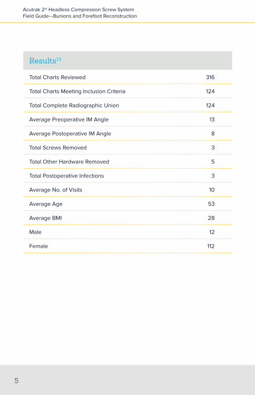
Results13
Total Charts Reviewed 316
Total Charts Meeting Inclusion Criteria 124
Total Complete Radiographic Union 124
Average Preoperative IM Angle 13
Average Postoperative IM Angle 8
Total Screws Removed 3
Total Other Hardware Removed 5
Total Postoperative Infections 3
Average No. of Visits 10
Average Age 53
Average BMI 28
Male 12
Female 112

Acutrak 2® Headless Compression Screw System Field Guide—Bunions and Forefoot Reconstruction
6
DiscussionThe results of this retrospective investigation demonstrate that fully threaded headless compression screws (Acutrak®, from Acumed LLC, Hillsboro, OR) are effective as a primary form of fixation for first metatarsal osteotomies.13
Of the three screws removed in this study only one was removed because of pain associated with the hardware. “In review of this case, the screw had been left proud and as such caused irritation. Surgeon error was the cause for extraction, and not hardware failure. The other screws were removed for infection and per patient request (no pain reported).”13
While complications have been reported with hallux valgus surgery, hardware irritation or failures have not always been documented. “Removal of hardware has been reported in up to 7% of the cases.”10 In this investigation the researchers found only 2% of the screws required removal, with no failure of fixation noted.13
Acutrak screws offer the surgeon an alternative to conventional hardware. The fully threaded screw provides the greatest push-out force, highest amount of retained compression after cyclic loading, and highest resistance to torsional loading compared to AO and Herbert screws in cadaveric and synthetic bone material.9 Compression is achieved through two key features that work together—the variable thread pitch and tapered profile. The wider thread pitch at the tip of the screw penetrates the bone faster than the finer trailing threads, compressing the two fragments gradually as the screw is advanced. The tapered profile allows the threads to purchase new bone with each turn, gaining compression and maximizing pullout strength along its entire length.

Acutrak 2® Headless Compression Screw System Field Guide—Bunions and Forefoot Reconstruction
7
Parallel Fixation and Immediate Weight Bearing of the First MetatarsalA 2011 retrospective investigation by John G. Fleischli, DPM, Terese J. Laughlin, DPM, and Jeffery W. Fleischli, DPM, highlighted outcomes of Acutrak usage coupled with a 3 to 4 hole plate in Lapidus arthrodesis.14 A summary of this investigation, which was performed with financial support from Acumed, can be found below.
IntroductionFirst metatarsal cuneiform arthrodesis (Lapidus arthrodesis) is popular for the correction of hallux valgus deformity. Traditional fixation techniques require prolonged periods of non-weight bearing including suture, Kirschner wires, screws, and plates. “Incorporating plate fixation stabilizes the arthrodesis site, yet most surgeons agree plate fixation alone is not optimal.”14
Gruber et al (quoted by Fleischli) speculates that “the addition of the compression screw across the fusion site in combination with plate fixation achieves interfragmentary friction and neutralizes plantar tensile forces.”16 Position of the plate for the Lapidus arthrodesis varies in published reports. “While medial placement over the joint remains popular, this position does not resist the forces of weight-bearing (torsional and sagittal plane) adequately. Optimal plate position would be on the plantar surface of the arthrodesis site, yet this is not practical due to technical difficulties.”14
Traditional postoperative care includes non-weight bearing for up to six weeks. More recently Basile et al (quoted by Fleischli) notes that, “early ambulation with full weight bearing has been described with success.”23 To assure complete union of the arthrodesis site, extremely stable fixation is advisable. Klos et al “used locking (fixed angle) plates to allow earlier resumption of weight bearing and improve bony union with the Lapidus procedure.”18 Flieschli et al hypothesized that “the combination of a plantar headless compression screw with dorsal plating will produce the needed compression and stabilization following a Lapidus arthrodesis to allow immediate protected weight bearing with predictable and consistent results.” In this retrospective, Fleischli et al retrospectively evaluated patients treated for hallux valgus deformity with a Lapidus type arthrodesis using a combination of plantar headless compression screw with dorsal plating.14
Acutrak 2® Headless Compression Screw System Field Guide—Bunions and Forefoot Reconstruction
8
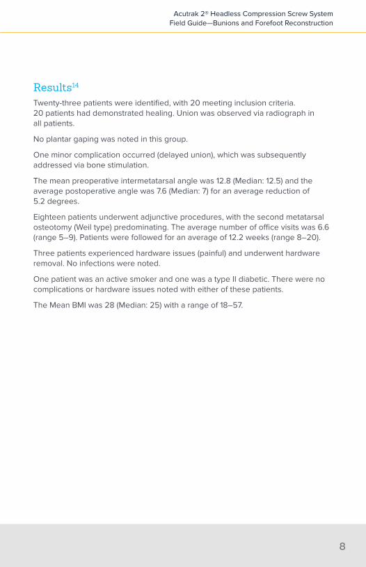
Results14
Twenty-three patients were identified, with 20 meeting inclusion criteria. 20 patients had demonstrated healing. Union was observed via radiograph in all patients.
No plantar gaping was noted in this group.
One minor complication occurred (delayed union), which was subsequently addressed via bone stimulation.
The mean preoperative intermetatarsal angle was 12.8 (Median: 12.5) and the average postoperative angle was 7.6 (Median: 7) for an average reduction of 5.2 degrees.
Eighteen patients underwent adjunctive procedures, with the second metatarsal osteotomy (Weil type) predominating. The average number of office visits was 6.6 (range 5–9). Patients were followed for an average of 12.2 weeks (range 8–20).
Three patients experienced hardware issues (painful) and underwent hardware removal. No infections were noted.
One patient was an active smoker and one was a type II diabetic. There were no complications or hardware issues noted with either of these patients.
The Mean BMI was 28 (Median: 25) with a range of 18–57.

Acutrak 2® Headless Compression Screw System Field Guide—Bunions and Forefoot Reconstruction
9
DiscussionNon-healing rates for the first metatarsal cuneiform arthrodesis with patients non-weight bearing postoperatively have been reported to be 3%–12%.18 In this retrospective evaluation of 23 patients, the reviewer found “superior results with no non-unions and 1 patient experiencing delayed union.”14
“Parallel fixation is achieved by placing a compression screw along the plantar arthrodesis site in combination with a dorsal plate. This allows the strongest compressive forces at the plantar surface where failure usually occurs as demonstrated by plantar gapping. The dorsal plate resists the torsional and sagittal plane forces of weight bearing.”14
The reviewers noted that screw choice is important in these procedures and the choice of the Acutrak 2 was made due to the screw’s ability to provide compression along its entire length, making it a preferred choice for fixation.
The reviewers concluded that “parallel screw and plate fixation of first metatarsal-cuneiform arthrodesis offers an excellent alternative to previously described fixation techniques.”14
Gruber et al (quoted by Fleischli) found that friction between the bones was an important part of stability surrounding the Lapidus arthrodesis site. Plate fixation alone was found to provide inferior compression between the bones when compared with screw fixation. “Screw fixation demonstrated superior stability in cadaver models.”16
The reviewers speculate that the combination of screw and plate fixation when placed in a parallel fashion would allow better outcomes. “The plantar placement of the screw offers stability, compression and friction between the bone ends, while better resisting the sagittal plane forces of weight bearing. The dorsal plate further stabilizes the arthrodesis in the sagittal plane and helps neutralize the torsional forces.”14

Acutrak 2® Headless Compression Screw System Field Guide—Bunions and Forefoot Reconstruction
10
ConclusionsThe reviewers found that “a combination of a plantar screw with a dorsal plate offers excellent fixation of the Lapidus arthrodesis in a retrospective evaluation.”14 The parallel nature of the two types of fixation, in combination with good bone to bone compression and resistance to sagittal (weight-bearing) forces may allow immediate ambulation without an increase in complications.14

Acutrak 2® Headless Compression Screw System Field Guide—Bunions and Forefoot Reconstruction
11
Acumed developed Acutrak screw technology to provide a headless compression-holding solution to fix fractures. It features the first fully threaded bone screw with a continuously variable thread pitch along the entire length of the screw.
The Acutrak 2 Headless Compression Screw System is composed of 65 unique screw size options to fit a wide variety of applications throughout the body. Backed by more than 25 years of clinical data and referenced in more than 100 studies in peer-reviewed journals, the Acutrak family of screws has demonstrated efficacy in hand, wrist, foot, and ankle applications.
Design Objectives1. Minimize likelihood of soft tissue irritation through headless fixation1
2. Achieve compression in fracture fixation with a fully threaded construct3. Achieve compression over a wider range of insertion depths than Standard AO
cannulated screws and Herbert/Whipple HCS screws4. Enable fixation in bone with cancellous-based thread design
Acutrak 2® Technology

LargerPitch
SmallerPitch
AveragePitch
Acutrak 2® Headless Compression Screw System Field Guide—Bunions and Forefoot Reconstruction
12
Fully Threaded Continuously Variable PitchDesigned to meet the above objectives, Acutrak screws deliver a new category of bone screw fixation that goes beyond headed and differential pitch screw options. It features a unique, patented thread pitch that varies continuously from tip to tail. This enables each screw rotation to engage threads into new bone along the screw’s entire length. As each successive individual thread advances faster than the trailing thread counterpart, the conical shape becomes seated into bone.
Key Features of the Acumed Acutrak 2® Headless Compression Screw System
⊲ Sterile and non-sterile implants ⊲ Compression
• Continuously variable pitch is created by having a wider thread pitch at the tip of the screw followed by finer trailing threads; this allows the screw to penetrate the bone faster at the tip than at the tail, which generates compression across the fracture site
⊲ Headless feature ⊲ Intended to reduce risk of impingement or soft tissue irritation compared to
that of headed screws when implanted in or around articular regions. ⊲ Soft tissue dissection may be minimized through percutaneous insertion,
which is facilitated by cannulation of the screw ⊲ Refinements when compared to the original Acutrak screw
• Helical relief flutes at the tip of the screw are designed to aid in the removal of bone during screw insertion
∙ Available in Acutrak 2: 4.7, 5.5, and 7.5 screws only

Acutrak 2® Headless Compression Screw System Field Guide—Bunions and Forefoot Reconstruction
13
• When used with the long drill, the cutting flutes at the tip of the Acutrak 2 screws feature self-cutting capabilities to aid during screw insertion
• The large diameter guide wires are designed to allow for provisional stabilization of the fixation site and accurate screw placement while reducing the risk of bending the wire
• Decreased screw depth sensitivity is achieved through pairing a cylindrical drill with a tapered profile drill; this eliminates the requirement of “downsizing” as described for the original Acutrak screw and other headless compression screws
• Surgical technique is consistent between screw families ⊲ Biomechanical performance
• Biomechanical studies have shown fully threaded, headless screws maintain compression for a greater number of cycles in comparison to partially threaded screws9
• When compared to traditional (AO) and differential (Herbert) bone screws, Acutrak screws were shown to have:
∙ Greater push-out force than the Herbert bones screws9
∙ The highest amount of retained compression after cyclic loading9
∙ The highest resistance to torsional loading in cadaveric and synthetic bone material9
⊲ Broad base of patient indications addressed• The Acutrak 2 families of product address nearly 20 of the most common
indications in the hand, wrist, foot, and ankle ⊲ Clinical and biomechanical data breadth
• More than 100 published studies offer biomechanical and clinical usage analysis

Acutrak 2® Headless Compression Screw System Field Guide—Bunions and Forefoot Reconstruction
14
Biomechanical Support
Interfragmentary Compression and Durability of Interfragmentary Compression Significantly Influence HealingAt least one animal study suggests that fracture stabilization that allows excessive shear motion at the fracture site impairs healing. The authors suggest that fracture fixation should therefore be performed with a minimization of shear motion.11
Cadaveric studies have demonstrated that carpal and metacarpal fractures may also fail to heal due to bending, rotational, and translational forces that strain the fracture site and cause shearing.19-22 These studies indicate that internal fixation should be as rigid as possible.
A previous study by Wheeler et al demonstrated that the Acutrak screw enabled fracture fragment stability in terms of compression achieved, pullout strength, and resistance to torque.9 In comparison to Herbert screws, the Acutrak screws achieved greater compression, maintained compression over a greater depth, and had a greater push-out force.9 The Acutrak screw also required greater torque to break fragment contact and maintained compression after cyclic loading better than either AO or Herbert screws.9
Improved Compression in Second Generation Headless ScrewsPrior to the headless compression screw, internal fixation options included open or percutaneous guide wire fixation or open reduction with headed lag screws. “Guide wire fixation had a propensity for fracture distraction, fracture instability, and secondary loss of reduction. Open lag screw fixation could result in either poor compression or joint arthrosis, as the head of the screw could reside on the articular surface and therefore cause secondary joint injury.”12 During the 1990s, cannulated headless compression screws were popular, when used with an open or percutaneously placed guide wire, from the volar and dorsal approach. Assari et al (quoted by Fleischli) assessed the biomechanical characteristics of the first generation Herbert/Whipple screw versus various next generation headless compression technologies.12
The Acutrak 2 Mini was cited as generating the greatest compressive force when compared with these other second generation technologies.12 In the same study, the Acutrak 2 Mini was shown to have no reduction in compression due to over-fastening, unlike some of the other screws studied.12

Com
pres
sive
For
ce (N
)
Screw Rotation (1 turn = 360 degrees)Flush
-8 -7 -6 -5 -4 -3 -2 -1 0 1 2 3
35
30
25
20
15
10
5
0
Acutrak (AC)
Traditional bone screws (AO)
Herbert (H)
Acutrak 2® Headless Compression Screw System Field Guide—Bunions and Forefoot Reconstruction
15
Acutrak® Technology’s Larger “Window of Compression”All bone screw technologies have a “window of compression” that determines the number of screw rotations needed to reach a maximum compressive force (beyond which further rotations decrease this value). Traditional bone screws have a narrow window of compression as compared to differentially pitched screws. This narrow window results in a fixation construct that is more sensitive to loss of compression due to over rotation and the stripping of thread purchase. Conversely, Acutrak technology has a wide window of compression, which is less sensitive to stripping the bone and is more flexible in its placement depth enabling a maximum amount of compression.9
The diagram below illustrates the window of compression for Acutrak technology, traditional bone screws (AO) and differential pitch screws (Herbert).9
The above graph illustrates the window of screw rotations during which each screw delivers maximum compressive force. The Acutrak screw has the largest window of compression, which is attributed to the additive property of each variable thread pitch providing compression on the fully threaded screw.

1. Greater Push-out Strength
Foam Bone
Pus
h-ou
t For
ce (N
)
300
250
200
150
100
50
0
ACAOH
AC > AO > H(p < 0.05)
AC, AO > H(p < 0.05)
Acutrak® screws have the highest push-out force when compared to AO & Herbert bone screws (AC)9
Acutrak 2® Headless Compression Screw System Field Guide—Bunions and Forefoot Reconstruction
16
Enhanced Facture Fixation BiomechanicsPullout strength and resistance to cyclic and torsional loading are key measurable elements of bone screw fixation performance. The performance of Acutrak (AC) in each of these elements was compared to traditional (AO) and differential (Herbert/H) bone screws. A summary of the results is shown in the figures below:
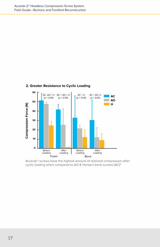
2. Greater Resistance to Cyclic Loading
Foam Bone
Com
pres
sion
For
ce (N
)
60
50
40
30
20
10
0
ACAOH
AC > AO > H(p < 0.05)
AC > AO, H(p < 0.05)
AC > H(p < 0.05)
AC, AO > H(p < 0.05)
BeforeLoading
AfterLoading
BeforeLoading
AfterLoading
Acutrak® screws have the highest amount of retained compression after cyclic loading when compared to AO & Herbert bone screws (AC)9
Acutrak 2® Headless Compression Screw System Field Guide—Bunions and Forefoot Reconstruction
17

3. Greater Resistance to Torsional Loading
Torq
ue (N
-mm
)
1000
500
400
300
200
100
0
ACAOH
AC > AO > H(p < 0.05)
900
800
700
600
Acutrak® screws have the highest resistance to torsional loading when compared to AO & Herbert bone screws (AC)9
Acutrak 2® Headless Compression Screw System Field Guide—Bunions and Forefoot Reconstruction
18

Acutrak 2® Headless Compression Screw System Field Guide—Bunions and Forefoot Reconstruction
19
Mau Osteotomy
Weil Osteotomy
7
2
6
MTP Fusion
Ludloff Osteotomy
1
3
8
Chevron Osteotomy
Akin Osteotomy
Lapidus4
5 Scarf

Akin Osteotomy . . . . . . . . . . . . . . . . . . . . . .24
First Metatarsophalangeal Joint Arthrodesis (MTP Fusion) . . . . . . . . . . . . . 30
Chevron Osteotomy . . . . . . . . . . . . . . . . . .38
Lapidus Bunionectomy . . . . . . . . . . . . . . . .44
Scarf (Z) Bunionectomy . . . . . . . . . . . . . . . .52
Weil Osteotomy—Correction of Lesser Metatarsal(s) . . . . . . . . . . . . . . . . . . 60
Mau Osteotomy . . . . . . . . . . . . . . . . . . . . . 68
Ludloff Osteotomy . . . . . . . . . . . . . . . . . . . .74
Atlas of Procedures
1
Section
2
3
4
5
6
7
8


Aki
nA
kin
Akin Osteotomy
Product: Acutrak 2® Micro
Typical Size: 18–24 mm
Akin Osteotomy

Acutrak 2® Headless Compression Screw System Field Guide—Bunions and Forefoot Reconstruction
24
Incision ⊲ The incision is made from the medial side and extended distally ⊲ The capsule is opened longitudinally and the joint is presented
Akin Osteotomy
Acutrak 2® Headless Compression Screw System Field Guide—Bunions and Forefoot Reconstruction
2525
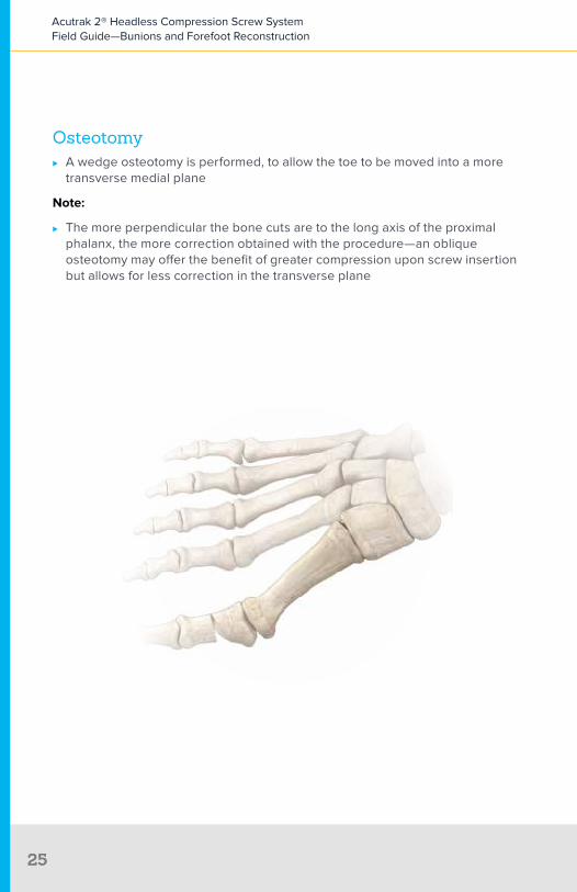
Osteotomy ⊲ A wedge osteotomy is performed, to allow the toe to be moved into a more
transverse medial plane
Note:
⊲ The more perpendicular the bone cuts are to the long axis of the proximal phalanx, the more correction obtained with the procedure—an oblique osteotomy may offer the benefit of greater compression upon screw insertion but allows for less correction in the transverse plane

Acutrak 2® Headless Compression Screw System Field Guide—Bunions and Forefoot Reconstruction
26
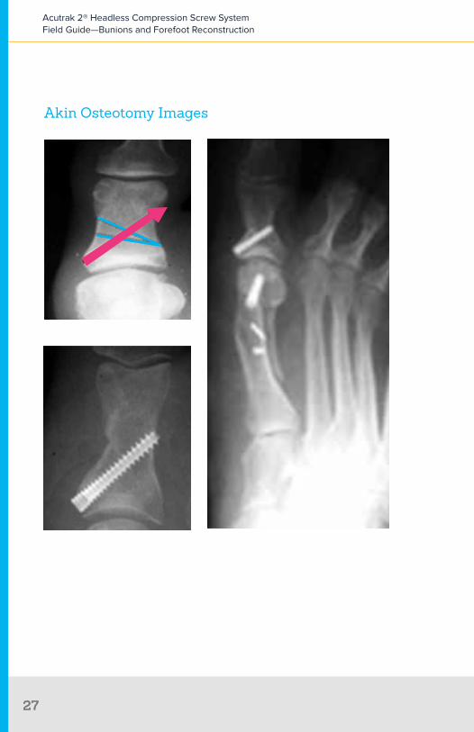
FixationAcutrak 2® Micro
⊲ The guide wire is aimed in a lateral/distal/dorsal direction until it breaches the lateral cortex just proximal to the interphalangeal joint
• The guide wire can be visualized (depending on incision placement) or felt with the finger just under the skin
⊲ The wire is then retracted so that the tip is just penetrating the lateral cortex ⊲ The screw sizer is used to measure the depth of the guide wire insertion
• Downsizing is unnecessary in this application ⊲ In particularly hard bone, the entire length of the wire can be drilled using the
long drill, otherwise just the proximal aspect is drilled with the profile drill ⊲ By design, most of the screw threads will purchase the soft intramedullary
bone of the phalanx upon insertion• If one of the threads purchases the cortex this is acceptable
⊲ Screw placement is made from the proximal medial aspect of the proximal phalanx
Acutrak 2® Headless Compression Screw System Field Guide—Bunions and Forefoot Reconstruction
2727
Akin Osteotomy Images

First Metatarsophalangeal Joint Arthrodesis
MT
P Fu
sion
Product: Acutrak 2® Mini and Optional 3- or 4-Hole Acumed Dorsal Plate
Typical Size: 26–30 mm
First Metatarsophalangeal Joint Arthrodesis

Acutrak 2® Headless Compression Screw System Field Guide—Bunions and Forefoot Reconstruction
30
Incision ⊲ The incision is made dorsal or dorsal medial to allow good exposure to the
entire joint
First Metatarsophalangeal Joint Arthrodesis (MTP Joint Fusion)

Acutrak 2® Headless Compression Screw System Field Guide—Bunions and Forefoot Reconstruction
31
Joint Preparation ⊲ Joint preparation is critical for this procedure
• As with any arthrodesis, removal of all hypertrophic bone from the joint and resection of cartilage is the first step
• With good exposure, the subchondral bone is removed down to the level of good bleeding bone
∙ Reamers are recommended for removal of this subchondral bone• To use the reamers, a guide wire is placed centrally in the metatarsal head• An appropriate size convex reamer is then used to form the surface
of the metatarsal head and remove bone down to the level of good bleeding bone
Acutrak 2® Headless Compression Screw System Field Guide—Bunions and Forefoot Reconstruction
32
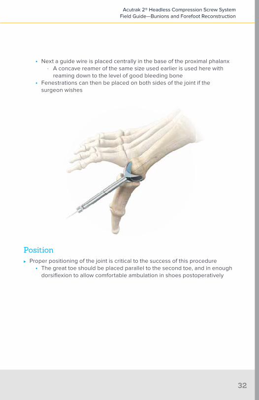
• Next a guide wire is placed centrally in the base of the proximal phalanx ∙ A concave reamer of the same size used earlier is used here with
reaming down to the level of good bleeding bone• Fenestrations can then be placed on both sides of the joint if the
surgeon wishes
Position ⊲ Proper positioning of the joint is critical to the success of this procedure
• The great toe should be placed parallel to the second toe, and in enough dorsiflexion to allow comfortable ambulation in shoes postoperatively

Acutrak 2® Headless Compression Screw System Field Guide—Bunions and Forefoot Reconstruction
33
FixationScrew Fixation
⊲ The joint is placed in the desired position and temporarily fixated with a guide wire
⊲ A second guide wire is inserted from the proximal side of the metatarsal head and directed distally at an angle across the joint space
⊲ Fluoroscopy may be used to evaluate the exact position of the guide wire ⊲ Use the screw sizer to measure for length of the implant ⊲ In particularly hard bone the entire length of the wire can be drilled using the
long drill, otherwise just the proximal aspect is drilled with the profile drill ⊲ The appropriate size Acutrak 2 screw is then inserted ⊲ A second Acutrak 2 screw (using the same series of steps described
previously) is inserted from the dorsal surface of the first metatarsal head to avoid contact with the plantar screw; this screw is directed proximally across the joint space and in a plantar direction

Acutrak 2® Headless Compression Screw System Field Guide—Bunions and Forefoot Reconstruction
34
Optional Additional FixationOptional Plate Fixation
⊲ A 4-hole or 3-hole plate is applied dorsally across the joint space• Screws are measured so that they will engage the plantar cortex

First Metatarsophalangeal Joint Arthrodesis Images
Acutrak 2® Headless Compression Screw System Field Guide—Bunions and Forefoot Reconstruction
35
Che
vron
Chevron Osteotomy
Product: Acutrak 2® Mini
Typical Size: 12–22 mm
Chevron Osteotomy
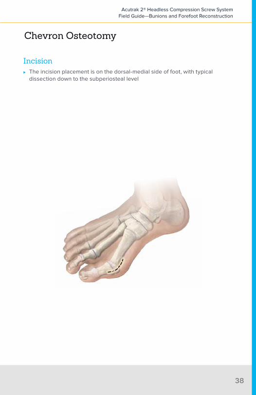
Incision ⊲ The incision placement is on the dorsal-medial side of foot, with typical
dissection down to the subperiosteal level
Chevron Osteotomy
Acutrak 2® Headless Compression Screw System Field Guide—Bunions and Forefoot Reconstruction
38
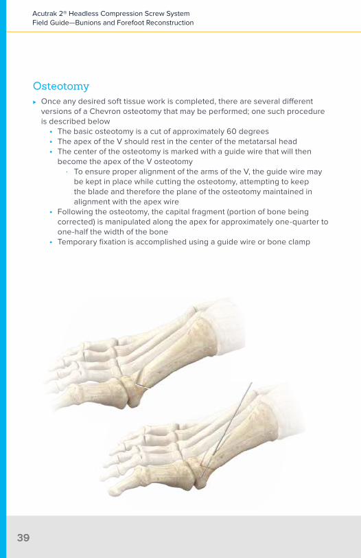
Osteotomy ⊲ Once any desired soft tissue work is completed, there are several different
versions of a Chevron osteotomy that may be performed; one such procedure is described below
• The basic osteotomy is a cut of approximately 60 degrees• The apex of the V should rest in the center of the metatarsal head• The center of the osteotomy is marked with a guide wire that will then
become the apex of the V osteotomy ∙ To ensure proper alignment of the arms of the V, the guide wire may
be kept in place while cutting the osteotomy, attempting to keep the blade and therefore the plane of the osteotomy maintained in alignment with the apex wire
• Following the osteotomy, the capital fragment (portion of bone being corrected) is manipulated along the apex for approximately one-quarter to one-half the width of the bone
• Temporary fixation is accomplished using a guide wire or bone clamp
Acutrak 2® Headless Compression Screw System Field Guide—Bunions and Forefoot Reconstruction
3939
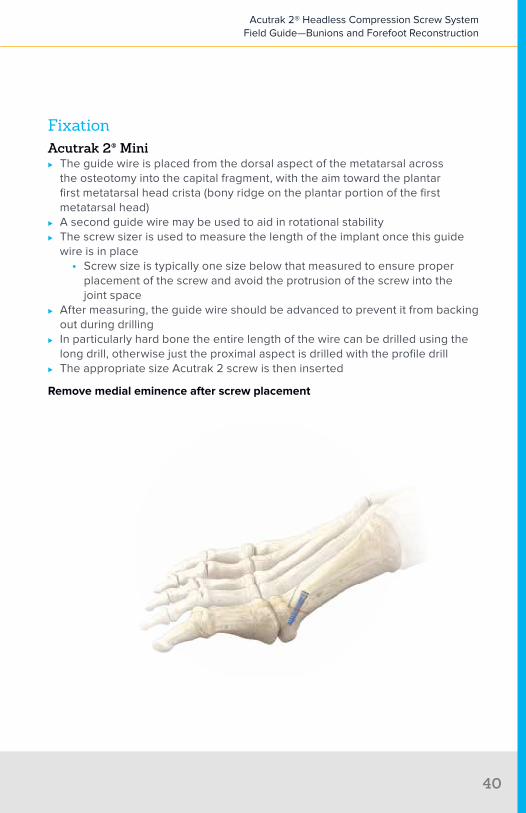
FixationAcutrak 2® Mini
⊲ The guide wire is placed from the dorsal aspect of the metatarsal across the osteotomy into the capital fragment, with the aim toward the plantar first metatarsal head crista (bony ridge on the plantar portion of the first metatarsal head)
⊲ A second guide wire may be used to aid in rotational stability ⊲ The screw sizer is used to measure the length of the implant once this guide
wire is in place• Screw size is typically one size below that measured to ensure proper
placement of the screw and avoid the protrusion of the screw into the joint space
⊲ After measuring, the guide wire should be advanced to prevent it from backing out during drilling
⊲ In particularly hard bone the entire length of the wire can be drilled using the long drill, otherwise just the proximal aspect is drilled with the profile drill
⊲ The appropriate size Acutrak 2 screw is then inserted
Remove medial eminence after screw placement
Acutrak 2® Headless Compression Screw System Field Guide—Bunions and Forefoot Reconstruction
40
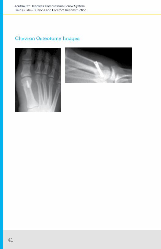
Chevron Osteotomy Images
Acutrak 2® Headless Compression Screw System Field Guide—Bunions and Forefoot Reconstruction
4141

Lapidus Bunionectomy
Lapi
dus

Primary FixationProduct: Acutrak 2® Standard
Typical Size: 28–32 mm
Optional Additional Fixation Product: Acumed 3-Hole or 4-Hole Plate
Secondary FixationProduct: Acutrak 2® Mini or Standard
Typical Size: 28–32 mm
Lapidus Bunionectomy

Incision ⊲ The incision is made medially or dorsal medially with typical dissection to the
joint level• Any soft tissue work or distal bone work is completed prior to
joint preparation• The initial exotosis is removed from the medial side of the first metatarsal
⊲ The tarsometatarsal (TMT) joint is opened and presented longitudinally through expansion of the dorsal incision
Lapidus Bunionectomy
Acutrak 2® Headless Compression Screw System Field Guide—Bunions and Forefoot Reconstruction
44

Joint Preparation ⊲ Initially the distal joint is resected in a vertical direction by means of an
oscillating saw ⊲ Correction is realized through removal of a lateral wedge from the proximal
joint surface• In order to prevent elevation, the wedge is removed from the
plantar surface ⊲ Joint preparation is critical for this procedure
• As with any arthrodesis, all hypertrophic bone and cartilage is removed from the fusion site—a combination of an AO elevator, a quarter-inch osteotome, straight and curved currettes, and a rongeur are recommended to facilitate this removal
• Subchondral bone is then removed down to the level of good bleeding bone
∙ Rongeurs are recommended for removal of this subchondral bone
Acutrak 2® Headless Compression Screw System Field Guide—Bunions and Forefoot Reconstruction
45

• Use a 2 mm drill bit to create a series of perforations in the arthrodesis surfaces to optimize surface area and blood flow—a limina spreader can be helpful for distraction
Positioning ⊲ The joint is positioned and temporarily fixated using a guide wire placed from
the medial aspect of the base of the first metatarsal into the cuneiform ⊲ Positioning is checked with fluoroscopy
Acutrak 2® Headless Compression Screw System Field Guide—Bunions and Forefoot Reconstruction
46

Initial Fixation Using an Acutrak 2® Standard Screw ⊲ A guide wire is inserted approximately 1 cm proximal to the joint surface on
the plantar aspect of the first metatarsal and placement is confirmed using fluoroscopy
⊲ The guide wire is angled from plantar slightly dorsal and in a lateral direction ⊲ The screw sizer is then used to determine depth and near cortex drilled with
the profile drill ⊲ The self-drilling design of the Acutrak 2 screw eliminates the need for use of
the long drill ⊲ A second Acutrak 2 screw (using the same series of steps described
previously) is inserted from the dorsal surface of the first metatarsal head to avoid contact with the plantar screw; this screw is directed proximally across the joint space and in a plantar direction
Optional 3- or 4-Hole Plate Placement ⊲ A 3- or 4-hole plate is placed across the dorsal surface of the joint ⊲ The plate will be roughly parallel to the plantar screw ⊲ The plate is held with a cortical screw placed distally and a cortical or
cancellous screw placed proximally in the cuneiform
Acutrak 2® Headless Compression Screw System Field Guide—Bunions and Forefoot Reconstruction
47
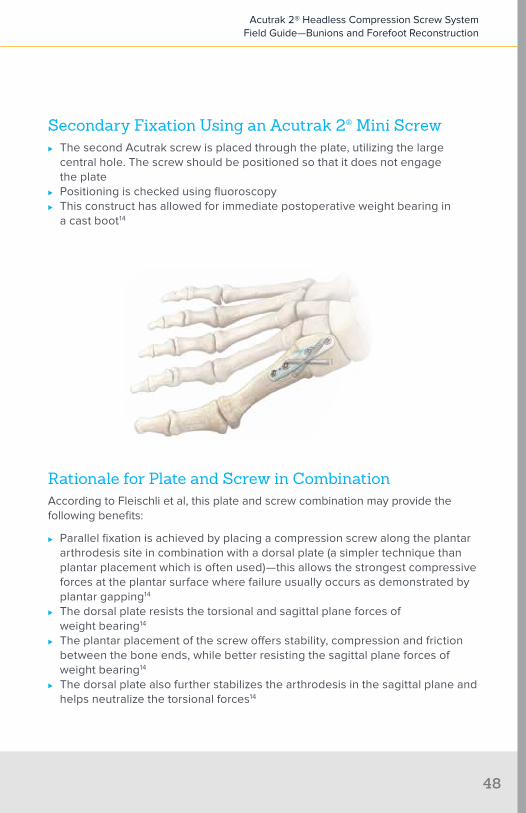
Secondary Fixation Using an Acutrak 2® Mini Screw ⊲ The second Acutrak screw is placed through the plate, utilizing the large
central hole. The screw should be positioned so that it does not engage the plate
⊲ Positioning is checked using fluoroscopy ⊲ This construct has allowed for immediate postoperative weight bearing in
a cast boot14
Rationale for Plate and Screw in CombinationAccording to Fleischli et al, this plate and screw combination may provide the following benefits:
⊲ Parallel fixation is achieved by placing a compression screw along the plantar arthrodesis site in combination with a dorsal plate (a simpler technique than plantar placement which is often used)—this allows the strongest compressive forces at the plantar surface where failure usually occurs as demonstrated by plantar gapping14
⊲ The dorsal plate resists the torsional and sagittal plane forces of weight bearing14
⊲ The plantar placement of the screw offers stability, compression and friction between the bone ends, while better resisting the sagittal plane forces of weight bearing14
⊲ The dorsal plate also further stabilizes the arthrodesis in the sagittal plane and helps neutralize the torsional forces14
Acutrak 2® Headless Compression Screw System Field Guide—Bunions and Forefoot Reconstruction
48

Lapidus Bunionectomy Images
Acutrak 2® Headless Compression Screw System Field Guide—Bunions and Forefoot Reconstruction
49

Sca
rf
Scarf (Z) Bunionectomy

Primary FixationProduct: Acutrak 2® Mini
Typical Size: 16–22 mm
Secondary FixationProduct: AcuTwist®
Typical Size: 12–18 mm
Scarf (Z) Bunionectomy
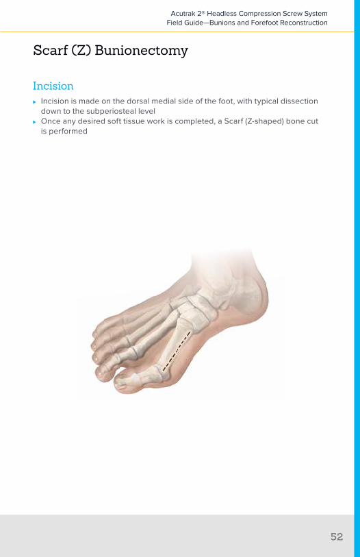
Incision ⊲ Incision is made on the dorsal medial side of the foot, with typical dissection
down to the subperiosteal level ⊲ Once any desired soft tissue work is completed, a Scarf (Z-shaped) bone cut
is performed
Scarf (Z) Bunionectomy
Acutrak 2® Headless Compression Screw System Field Guide—Bunions and Forefoot Reconstruction
52
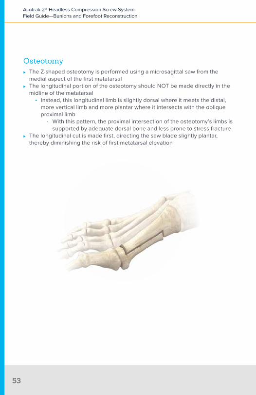
Osteotomy ⊲ The Z-shaped osteotomy is performed using a microsagittal saw from the
medial aspect of the first metatarsal ⊲ The longitudinal portion of the osteotomy should NOT be made directly in the
midline of the metatarsal• Instead, this longitudinal limb is slightly dorsal where it meets the distal,
more vertical limb and more plantar where it intersects with the oblique proximal limb
∙ With this pattern, the proximal intersection of the osteotomy’s limbs is supported by adequate dorsal bone and less prone to stress fracture
⊲ The longitudinal cut is made first, directing the saw blade slightly plantar, thereby diminishing the risk of first metatarsal elevation
Acutrak 2® Headless Compression Screw System Field Guide—Bunions and Forefoot Reconstruction
5353
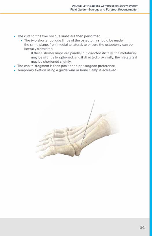
⊲ The cuts for the two oblique limbs are then performed• The two shorter oblique limbs of the osteotomy should be made in
the same plane, from medial to lateral, to ensure the osteotomy can be laterally translated
∙ If these shorter limbs are parallel but directed distally, the metatarsal may be slightly lengthened, and if directed proximally, the metatarsal may be shortened slightly
⊲ The capital fragment is then positioned per surgeon preference ⊲ Temporary fixation using a guide wire or bone clamp is achieved
Acutrak 2® Headless Compression Screw System Field Guide—Bunions and Forefoot Reconstruction
54

FixationInitial Fixation Using an Acutrak 2® Mini
⊲ The guide wire is placed from the dorsal aspect of the metatarsal across the osteotomy into the capital fragment; the point of aim is the plantar first metatarsal head crista
• The guide wire can be passed through the plantar cortex of the crista and then retracted to ensure the guide wire is in the subcortical bone of the first metatarsal head; fluoroscopy may also be used to confirm positioning
⊲ Measurements are taken once this wire is in place using the screw sizer• Screw size is typically one size below the measured length to ensure
proper placement of the screw and avoid protrusion of the screw into the joint space
⊲ Drill the dorsal cortex prior to insertion of the screw using the profile drill ⊲ The self-drilling design of the Acutrak 2 screw eliminates the need for
full drilling; however, if desired, the long drill can be used to drill the entire length of the guide wire
Acutrak 2® Headless Compression Screw System Field Guide—Bunions and Forefoot Reconstruction
5555

Secondary FixationSecondary Fixation Using an Acutrak 2® Micro or AcuTwist®
⊲ The second screw is placed proximally to the first• The guide wire or AcuTwist is pre-drilled in dense bone and measured
with the appropriate screw sizer ⊲ Fixation is accomplished in both the dorsal cortex and plantar cortex of the
first metatarsal• Several threads should engage both cortices
Remove medial eminence after screw placement
Acutrak 2® Headless Compression Screw System Field Guide—Bunions and Forefoot Reconstruction
56
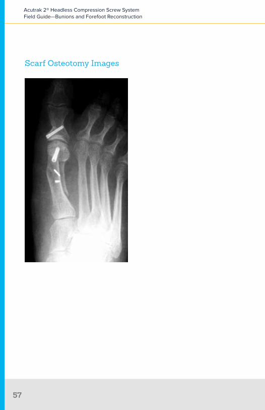
Scarf Osteotomy Images
Acutrak 2® Headless Compression Screw System Field Guide—Bunions and Forefoot Reconstruction
5757

Weil Osteotomy
Wei
l
Product: Acutrak 2® Micro or AcuTwist®
Typical Size: 10–12 mm
Weil Osteotomy

Incision ⊲ Incision is made over the joint of the impacted lesser metatarsal (2–5)
Weil Osteotomy
Acutrak 2® Headless Compression Screw System Field Guide—Bunions and Forefoot Reconstruction
60
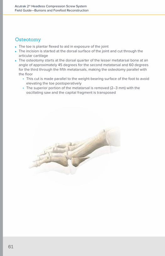
Osteotomy ⊲ The toe is plantar flexed to aid in exposure of the joint ⊲ The incision is started at the dorsal surface of the joint and cut through the
articular cartilage ⊲ The osteotomy starts at the dorsal quarter of the lesser metatarsal bone at an
angle of approximately 45 degrees for the second metatarsal and 60 degrees for the third through the fifth metatarsals, making the osteotomy parallel with the floor
• This cut is made parallel to the weight-bearing surface of the foot to avoid elevating the toe postoperatively
• The superior portion of the metatarsal is removed (2–3 mm) with the oscillating saw and the capital fragment is transposed
Acutrak 2® Headless Compression Screw System Field Guide—Bunions and Forefoot Reconstruction
61

⊲ The guide wire is then retracted to a level just below the plantar cortex prior to measurement
⊲ The head of the bone is then repositioned
Acutrak 2® Headless Compression Screw System Field Guide—Bunions and Forefoot Reconstruction
62

FixationAcutrak 2® Micro
⊲ Measure the guide wire using the screw sizer provided ⊲ After measuring, the guide wire should be advanced to prevent it from backing
out during drilling ⊲ In particularly hard bone the entire length of the wire can be drilled using the
long drill, otherwise just the proximal aspect is drilled with the profile drill ⊲ Insert screw ⊲ The screw should not penetrate the plantar cortex
Remove dorsal eminence following screw placement
Acutrak 2® Headless Compression Screw System Field Guide—Bunions and Forefoot Reconstruction
63
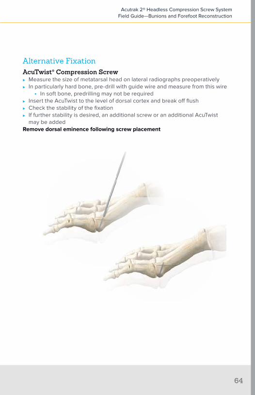
Alternative FixationAcuTwist® Compression Screw
⊲ Measure the size of metatarsal head on lateral radiographs preoperatively ⊲ In particularly hard bone, pre-drill with guide wire and measure from this wire
• In soft bone, predrilling may not be required ⊲ Insert the AcuTwist to the level of dorsal cortex and break off flush ⊲ Check the stability of the fixation ⊲ If further stability is desired, an additional screw or an additional AcuTwist
may be addedRemove dorsal eminence following screw placement
Acutrak 2® Headless Compression Screw System Field Guide—Bunions and Forefoot Reconstruction
64
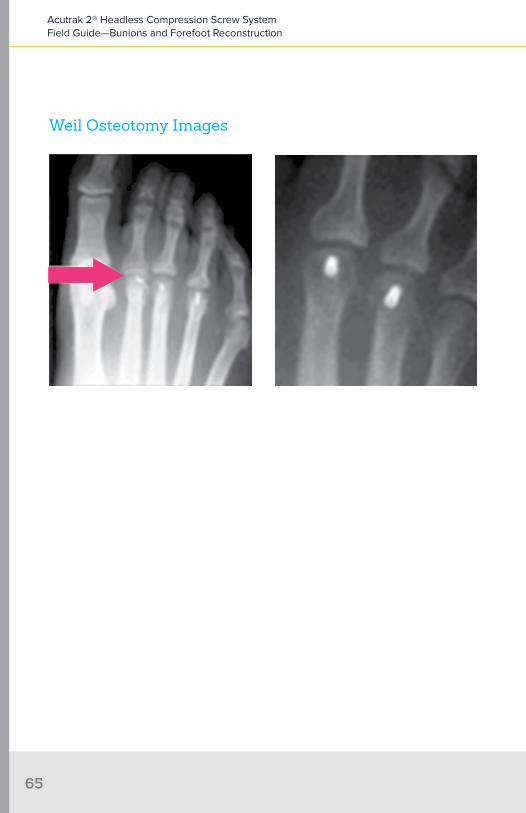
Weil Osteotomy Images
Acutrak 2® Headless Compression Screw System Field Guide—Bunions and Forefoot Reconstruction
65

Mau Osteotomy
Mau

Primary FixationProduct: Acutrak 2® Mini
Typical Size: 16–22 mm
Secondary FixationProduct: Acutrak 2® Mini or Micro
Typical Size: 12–16 mm; 14 mm is the most common
Mau Osteotomy

Incision ⊲ Incision is made on the medial side of the foot longitudinally
Mau Osteotomy
Acutrak 2® Headless Compression Screw System Field Guide—Bunions and Forefoot Reconstruction
68

Osteotomy ⊲ Osteotomy begins 1 cm distal to the first tarsometatarsal (TMT) joint at the
plantar cortex in the medial side ⊲ Osteotomy is angled from plantar proximal to dorsal distal ⊲ Once the osteotomy is complete, an axis guide is established at the
proximal portion of the osteotomy using a small guide wire which is angled perpendicular to the osteotomy, allowing the distal fragment to pivot laterally and reduce the intermetatarsal angle
Acutrak 2® Headless Compression Screw System Field Guide—Bunions and Forefoot Reconstruction
6969

FixationPrimary Fixation
⊲ The first screw is placed across and perpendicular to the completed portion of the osteotomy from dorsal to plantar
Secondary Fixation ⊲ A second screw is placed dorsal to plantar and parallel to the first screw
perpendicular to the osteotomy
Remove medial eminence after screw placement
Acutrak 2® Headless Compression Screw System Field Guide—Bunions and Forefoot Reconstruction
70

Mau
Ludl
off
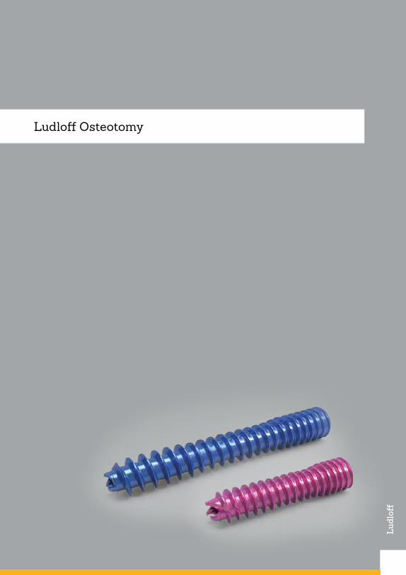
Ludloff Osteotomy

Primary FixationProduct: Acutrak 2® Mini
Typical Size: 16–22 mm
Secondary FixationProduct: Acutrak 2® Mini or Micro
Typical Size: 12–16 mm
Ludloff Osteotomy

Incision ⊲ Incision is made on the medial side of the foot longitudinally
Ludloff Osteotomy
Acutrak 2® Headless Compression Screw System Field Guide—Bunions and Forefoot Reconstruction
74

Osteotomy ⊲ Osteotomy begins at the dorsal aspect of the proximal metatarsal, near the
tarsometatarsal (TMT) joint ⊲ The osteotomy is made parallel to the weight-bearing surface from dorsal
proximal to plantar distal ⊲ Only the dorsal two thirds of the osteotomy are completed with the initial cut
Acutrak 2® Headless Compression Screw System Field Guide—Bunions and Forefoot Reconstruction
75

FixationPrimary Fixation
⊲ The screw is placed across and perpendicular to the completed portion of the osteotomy from dorsal to plantar, tightened enough to demonstrate effective compression and then backed off to allow for pivoting of the fragments
⊲ The osteotomy is then completed ⊲ The distal fragment of osteotomy is then rotated about the screw to correct the
intermetatarsal angle
Secondary Fixation ⊲ A second screw is placed plantar to dorsal, perpendicular to the osteotomy
Remove medial eminence after screw placement
Acutrak 2® Headless Compression Screw System Field Guide—Bunions and Forefoot Reconstruction
76

References
1. Laughlin TJ. Complications of distal first metatarsal osteotomies. J Foot Ankle Surg. 1995;34(6):524-531.
2. Armstrong DG, Pupp GR, Harkless LB. Our fixation with fixation: are screws clinically superior to external wires in distal first metatarsal osteotomies? J Foot Ankle Surg. 1997;35(5):353-355.
3. Botte MJ, Davis JL, Rose BA, et al Complication of smooth pin fixation of fractures and dislocations in the hand and wrist. Clin Orthop Relat Res 1992;276:194-201.
4. Heim U, Pfeiffer KM, eds. Internal Fixation of Small Fractures Technique Recommended by the AO-ASIF Group. 3rd ed. Berlin: Springer-Verlag; 1988.
5. Mancuso JE, Abramow SP, Bloom WB, Carioscia MP, Landsman MJ. Smooth Kirschner (K) wire fixation of distal metaphyseal osteotomy bunionectomies: a 10-year retrospective surgery. J Foot Surg. 1992;31(3):276-284.
6. Wanivenhaus AH, Felder-Busztin H. Basal osteotomy of the first metatarsal for the correction of metatarsus primus varus associated with hallux valgus. Foot Ankle. 1988;8(6):337-343.
7. Fadel GE, Hussain SM, Sripada S, Jain AS. Fixation of first metatarsal basal osteotomy using Acutrak screw. Foot Ankle. 2008;14:21-25.
8. Mitchell CL, Fleming JL, Allen R, Glenney C, Sanford GA. Osteotomy-bunionectomy for hallux valgus. J Bone Joint Surg Am. 1958;40:41-60. Cited by Fleischli et al (see no. 14).
9. Wheeler DL, McLoughlin SW. Biomechanical assessment of compression screws. Clin Orthop Relat Res.1998;350:237–245.
10. Chiodo CP, Schon LC, Myerson MS. Clinical results with the Ludloff osteotomy for correction of adult hallux valgus. Foot Ankle Int. 2004;25(8):532-536. Cited by Fleischli et al (see no. 13).
11. Augat P, Burger J, Schorlemmer S, Henke T, Peraus M, Claes L. Shear movement at the fracture site delays healing in a diaphyseal fracture model. J Orthop Res. 2003;21:1011–1017.
12. Assari S, Darvish K, Ilyas A. Biomechanical analysis of second-generation headless compression screws. J Injury. 2012: 1159-1165.
13. Fleischli J, Laughlin T, Fleischli J. Fully threaded compression screw for fixation of first metatarsal osteotomies: a retrospective. Paper presented at: American College of Foot & Ankle Surgeons Annual Meeting; February 2008.
14. Fleischli J. Laughlin T. Fleischli J. Parallel fixation method with early weight bearingfollowing lapidus arthrodesis. Paper presented at: Annual Scientific Conference of American College of Foot & Ankle Surgeons; March 9, 2011; Ft. Lauderdale, FL.
15. Wulker N, Mittag F. The Treatment of Hallux Valgus. Dept Orthop Surg. Tübingen University Hospital: Dtsch Arztebl Int 2012; 109(49): 857–68.
Acutrak 2® Headless Compression Screw System Field Guide—Bunions and Forefoot Reconstruction
77

16. Gruber F, Sinkov VS, Bae S-Y, Parke BG, Schon LC. Crossed screws versus dorsomedial locking plate with compression screw for first metatarsocuneiform arthrodesis: a cadaver study. Foot Ankle Int. 2008;29(9):927-930. Cited by Fleischli et al (see no. 14).
17. Klos K, Gueorguiev B, Muckley T, et al. Stability of medial locking plate and compression screw versus two crossed screws for lapidus arthrodesis. Foot Ankle Int. 2010;31(2):158-163. Cited by Fleischli et al (see no. 14).
18. Thompson IM, Bohay DR, Anderson JG. Fusion rate of first tarsometatarsal arthrodesis in the modified lapidus procedure and flatfoot reconstruction. Foot Ankle Int. 2005;26(9):698-703.
19. Augat P, Burger J, Schorlemmer S, Henke T, Peraus M, Claes L. Shear movement at the fracture site delays healing in a diaphyseal fracture model. J Orthop Res. 2003;21(6):1011–1017.
20. Kobayashi M, Garcia-Elias M, Nagy L, Ritt MJ, An KN, Cooney WP, Linscheid RL. Axial loading induces rotation of the proximal carpal row bones around unique screw-displacement axes. J Biomech. 1997;30:1165–1167.
21. Garcia-Elias M. Kinetic analysis of carpal stability during grip. Hand Clin. 1997;13:151–158.
22. Smith DK, Cooney WP III, An KN, Linscheid RL, Chao EY. The effects of simulated unstable scaphoid fractures on carpal motion. J Hand Surg Am. 1989;14A:283–291.
23. Basile P, Cook EA, Cook JJ. Immediate weight bearing following modified lapidus arthrodesis. J Foot Ankle Surg. 2010;49:459-464.
Acutrak 2® Headless Compression Screw System Field Guide—Bunions and Forefoot Reconstruction
78


Appendices

App
endi
x 1:
Cor
rect
iona
l Pro
cedu
res15
No.
Nam
eP
rinc
iple
Site
App
licat
ion
1A
kin
Cor
rect
ive
Ost
eoto
my
Prox
imal
Pha
lana
xU
sed
in h
allu
x va
lgus
in
terp
hala
ngeu
s
2C
hevr
onC
orre
ctiv
e O
steo
tom
yFi
rst M
etat
arsa
l, D
iaph
ysea
lU
sed
in m
ild d
efor
miti
es
3La
pidu
sFu
sion
Tars
omet
arsa
l Joi
ntU
sed
in c
ases
of T
MT-
1 jo
int
inst
abili
ty o
r ost
eoar
thrit
is
4M
etat
arso
phal
ange
al
Join
t Art
hrod
esis
Fusi
onM
etat
arso
phal
ange
al J
oint
Use
d in
sev
ere
defo
rmiti
es a
nd/o
r ha
llux
rigid
us
5Sc
arf
Cor
rect
ive
Ost
eoto
my
Firs
t Met
atar
sal,
Dia
phys
eal
Suita
ble
for c
orre
ctio
n of
mild
to
mod
erat
e de
form
ities
6W
eil
Cor
rect
ive
Ost
eoto
my
Less
er M
etat
arsa
ls (2
-5)
Use
d to
repa
ir to
e cl
awin
g or
m
etat
arsa
lagi
a
7M
auC
orre
ctiv
e O
steo
tom
yFi
rst M
etat
arsa
l, D
iaph
ysea
lU
sed
in m
oder
ate
to s
ever
e ha
llux
valg
us d
efor
mity
ass
ocia
ted
with
m
etat
arsu
s pr
imus
var
us
8Lu
dloff
Cor
rect
ive
Ost
eoto
my
Firs
t Met
atar
sal,
Dia
phys
eal
Use
d in
mod
erat
e to
sev
ere
hallu
x va
lgus
def
orm
ity a
ssoc
iate
d w
ith
met
atar
sus
prim
us v
arus
Acutrak 2® Headless Compression Screw System Field Guide—Bunions and Forefoot Reconstruction
81
No.
Nam
eP
rinc
iple
Site
App
licat
ion
1A
kin
Cor
rect
ive
Ost
eoto
my
Prox
imal
Pha
lana
xU
sed
in h
allu
x va
lgus
in
terp
hala
ngeu
s
2C
hevr
onC
orre
ctiv
e O
steo
tom
yFi
rst M
etat
arsa
l, D
iaph
ysea
lU
sed
in m
ild d
efor
miti
es
3La
pidu
sFu
sion
Tars
omet
arsa
l Joi
ntU
sed
in c
ases
of T
MT-
1 jo
int
inst
abili
ty o
r ost
eoar
thrit
is
4M
etat
arso
phal
ange
al
Join
t Art
hrod
esis
Fusi
onM
etat
arso
phal
ange
al J
oint
Use
d in
sev
ere
defo
rmiti
es a
nd/o
r ha
llux
rigid
us
5Sc
arf
Cor
rect
ive
Ost
eoto
my
Firs
t Met
atar
sal,
Dia
phys
eal
Suita
ble
for c
orre
ctio
n of
mild
to
mod
erat
e de
form
ities
6W
eil
Cor
rect
ive
Ost
eoto
my
Less
er M
etat
arsa
ls (2
-5)
Use
d to
repa
ir to
e cl
awin
g or
m
etat
arsa
lagi
a
7M
auC
orre
ctiv
e O
steo
tom
yFi
rst M
etat
arsa
l, D
iaph
ysea
lU
sed
in m
oder
ate
to s
ever
e ha
llux
valg
us d
efor
mity
ass
ocia
ted
with
m
etat
arsu
s pr
imus
var
us
8Lu
dloff
Cor
rect
ive
Ost
eoto
my
Firs
t Met
atar
sal,
Dia
phys
eal
Use
d in
mod
erat
e to
sev
ere
hallu
x va
lgus
def
orm
ity a
ssoc
iate
d w
ith
met
atar
sus
prim
us v
arus
App
endi
x 2:
Sev
erit
y an
d Tr
eatm
ent15
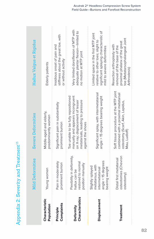
Mild
Def
orm
itie
sS
ever
e D
efor
mit
ies
Hal
lux
Val
gus
et R
igid
us
Cha
ract
eris
tic
Pop
ulat
ion
Youn
g w
omen
Mid
dle-
aged
and
eld
erly
, pr
edom
inan
tly w
omen
Elde
rly p
atie
nts
Pri
ncip
le
Com
plai
nts
Pain
in m
oder
atel
y pr
omin
ent b
unio
nSi
gnifi
cant
pai
n in
sub
stan
tially
pr
omin
ent b
unio
n
Insi
diou
s on
set o
f pai
n an
d
stiff
ness
abo
ut th
e gr
eat t
oe, w
ith
or w
ithou
t act
ivity
Def
orm
ity
Cha
ract
eris
tics
Flex
ibili
ty in
def
orm
ity,
hallu
x ca
n be
re
stor
ed to
nor
mal
po
sitio
n m
anua
lly
Toe
unab
le to
be
fully
repo
sitio
ned
man
ually
and
app
ears
inco
ngru
ent
on X
-ray
; dis
plac
emen
t of l
esse
r m
etat
arsa
ls, l
eadi
ng to
pre
ssur
e ag
ains
t the
sho
es
Ver
y lim
ited
dors
iflex
ion
of M
TP w
ith
adeq
uate
pla
ntar
flex
ion—
limite
d to
no
mot
ion
at M
TP jo
int
Dis
plac
emen
t
Slig
htly
spl
ayed
m
etat
arsu
s, w
ith
inte
rmet
atar
sal
angl
e <
15 d
egre
es
bear
ing
wei
ght
Sign
ifica
nt s
play
, with
inte
rmet
atar
sal
angl
e >
15 d
egre
es b
earin
g w
eigh
t
Lim
ited
spac
e in
the
first
MTP
join
t re
lativ
e to
oth
er to
es; s
light
to
sign
ifica
nt s
play
ing
char
acte
ristic
of
mild
to s
ever
e de
form
ities
Trea
tmen
tD
ista
l firs
t met
atar
sal
oste
otom
ies
(Che
vron
os
teot
omy)
Soft
tissu
e pr
oced
ure
at th
e M
TP jo
int
com
bine
d w
ith a
pro
xim
al m
etat
arsa
l os
teot
omy
(Sca
rf, A
kin,
Lap
idus
, M
au, L
udlo
ff)
Rese
ctio
n ar
thro
plas
ty w
ith
rem
oval
of t
he b
ase
of th
e pr
oxim
al p
hala
nx o
f the
gre
at
toe
(Met
atar
soph
alan
geal
Joi
nt
Art
hrod
esis
)
Acutrak 2® Headless Compression Screw System Field Guide—Bunions and Forefoot Reconstruction
82
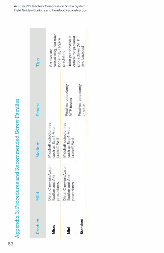
App
endi
x 3:
Pro
cedu
res
and
Rec
omm
ende
d S
crew
Fam
ilies
Pro
duct
Mild
Med
ium
Sev
ere
Tip
s
Mic
roD
ista
l Che
vron
/Aus
tin
fixat
ion
and
Aki
n pr
oced
ures
Mid
shaf
t ost
eoto
mie
s su
ch a
s Sc
arf,
Mau
, Lu
dloff
, Wei
l
Scre
ws
are
self-
drill
ing,
but
har
d bo
ne m
ay re
quire
pr
edril
ling
Join
t pre
para
tion
is
criti
cal f
or p
roxi
mal
pr
oced
ures
(MTP
an
d La
pidu
s)
Min
iD
ista
l Che
vron
/Aus
tin
fixat
ion
and
Aki
n pr
oced
ures
Mid
shaf
t ost
eoto
mie
s su
ch a
s Sc
arf,
Mau
, Lu
dloff
, Wei
l
Prox
imal
ost
eoto
my,
M
TP fu
sion
Sta
ndar
dPr
oxim
al o
steo
tom
y,
Lapi
dus
Acutrak 2® Headless Compression Screw System Field Guide—Bunions and Forefoot Reconstruction
83

App
endi
x 4:
Cor
rect
iona
l Pro
cedu
res—
Pro
duct
s an
d C
omm
on R
ange
of L
engt
hs16
No.
Pro
cedu
reP
rodu
ctC
omm
on R
ange
of L
engt
hs
1A
kin
Acu
trak
2®
Mic
ro o
r Acu
Twis
t®18
–24
mm
2C
hevr
onA
cutr
ak 2
Min
i12
–20
mm
3La
pidu
s2
x A
cutr
ak 2
Sta
ndar
d28
–32
mm
Opt
iona
l 3- o
r 4-H
ole
Lo
ckin
g Pl
ate
4M
etat
arso
phal
ange
al
Join
t Art
hrod
esis
2 x
Acu
trak
2 M
ini
26–
30 m
m
Opt
iona
l 3- o
r 4-H
ole
Lo
ckin
g Pl
ate
5Sc
arf
Acu
trak
2 M
ini
16–
22 m
m
Acu
Twis
t12
–16
mm
6W
eil
Acu
trak
2 M
icro
or A
cuTw
ist
10–
12 m
m
7M
auA
cutr
ak 2
Min
i16
–22
mm
Acu
Twis
t12
–18
mm
8Lu
dloff
2 x
Acu
trak
2 M
ini
12–
18 m
m
Acutrak 2® Headless Compression Screw System Field Guide—Bunions and Forefoot Reconstruction
84
Acu
trak
2®
Acu
trak
2: M
icro
8 m
m*
Acu
trak
2: M
ini
16 m
m*
Acu
trak
2: S
tand
ard
16 m
m*
Acu
trak
2: 4
.7
20
mm
*
Acu
trak
2: 5
.5
25
mm
*
Acu
trak
2: 7
.5
40
mm
*
Acu
trak
2
Par
t No.
AT2
-CX
X-S
and
A
T2-C
XX
AT2
-MX
X-S
and
A
T2-M
XX
AT2
-SX
X-S
and
A
T2-S
XX
30-0
XX
X a
nd
30-0
XX
X-S
30-0
0X
X a
nd
30-0
0X
X-S
30-0
XX
X a
nd
30-0
XX
X-S
Leng
ths
8 m
m–
14 m
m
(1 m
m in
crem
ents
), 16
mm
–30
mm
(2
mm
incr
emen
ts)
16 m
m–
30 m
m
(2 m
m in
crem
ents
)16
mm
–34
mm
(2
mm
incr
emen
ts)
20 m
m–
30 m
m
(2 m
m in
crem
ents
) 30
mm
–5
0 m
m
(5 m
m in
crem
ents
)
25 m
m–
60
mm
(5
mm
incr
emen
ts)
40 m
m–
120
mm
(5
mm
incr
emen
ts)
Tip
Dia
met
ers
2.5
mm
tip
3.5
mm
tip
4 m
m ti
p4.
5 m
m ti
p5
.2 m
m ti
p7
mm
tip
Tail
Dia
met
ers
2.8
mm
tail
3.6
mm
tail
4.1
mm
tail
4.7
mm
tail
5.5
mm
tail
7.5
mm
tail
Gui
de W
ire
WS-
09
06
ST,
80-1
524
Sin
gle
Troc
ar,
80-1
525
Dou
ble
Troc
arW
S-11
06
STW
S-14
07S
T80
-09
50
80-0
95
0
80-0
413
in A
T2-5
.5
Syst
em
80-0
970
non
-thr
eade
d 80
-09
71 th
read
ed
Gui
de W
ire
Dia
met
er.0
35"
(.9 m
m)
.045
" (1.
1 m
m)
.05
4" (1
.4 m
m)
.06
2" (1
.6 m
m)
.06
2" (1
.6 m
m)
.09
4" (2
.4 m
m)
Hex
Dri
ver
HT-
09
15H
T-11
20H
T-17
2580
-09
58
(can
nula
ted)
80
-09
59
(sol
id)
80-0
95
8 (c
annu
late
d)
80-0
95
9 (s
olid
)80
-09
78 (c
annu
late
d)
80-0
979
(sol
id)
Hex
Siz
e1.5
mm
2 m
m2.
5 m
m3
mm
3 m
m4
mm
Pro
file
Dri
ll
Par
t No.
AT2
-15
09
AT2
M-1
813
AT2
-25
1580
-09
4580
-09
55
, 80
-00
55
in
AT2
-5.5
Sys
tem
80-0
975
Pro
file
Dri
ll
Tip
Dia
met
er1.8
mm
tip
2.5
mm
tip
3.1
mm
tip
2.8
mm
tip
4 m
m ti
p4.
5 m
m ti
p
Pro
file
Dri
ll
Tail
Dia
met
er2.
9 m
m ta
il3.
4 m
m ta
il4.
1 m
m ta
il4.
7 m
m ta
il5
.5 m
m ta
il6
.9 m
m ta
il
Pro
file
Dri
ll Le
ngth
4.6
mm
8.2
mm
8.2
mm
16.2
mm
(to
2 m
m
band
)14
.5 m
m (t
o 2
mm
ba
nd)
24.3
mm
(to
2 m
m
band
)
Long
Dri
ll
Par
t No.
80-0
100,
80
-15
22A
T2M
-L18
13A
T2-L
2515
80-0
946
80-0
95
6, 8
0-0
05
6 in
A
T2-5
.5 S
yste
m80
-09
76
Long
Dri
ll D
iam
eter
1.9 m
m2.
7 m
m3.
2 m
m3.
3 m
m4
mm
5.3
mm
Long
Dri
ll Le
ngth
20 m
m, 3
6 m
m30
mm
34 m
m5
0 m
m6
0 m
m12
0 m
m
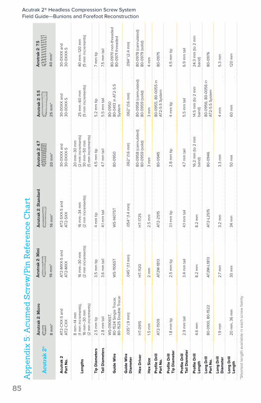
App
endi
x 5:
Acu
med
Scr
ew/P
in R
efer
ence
Cha
rt
*Sho
rtes
t len
gth
ava
ilab
le in
eac
h sc
rew
fam
ily
Acutrak 2® Headless Compression Screw System Field Guide—Bunions and Forefoot Reconstruction
85

Acu
trak
®A
cutr
ak M
ini
8 m
m*
Acu
trak
Sta
ndar
d
12.5
mm
*
Acu
trak
4/5
25
mm
*
Acu
trak
Plu
s
35
mm
*
Acu
trak
6/7
40
mm
*
Acu
trak
Par
t No.
ATM
-XX
X-S
AT-
1XX
X-S
AM
-00
XX
-SA
P-0
0X
X-S
AP-
67X
X-S
or A
P-6
71X
X-S
Leng
ths
8 m
m–
26 m
m
(2 m
m in
crem
ents
)12
.5 m
m–
30 m
m
(2.5
mm
incr
emen
ts)
25 m
m–
50
mm
(5
mm
incr
emen
ts)
35 m
m–
80 m
m
(5 m
m in
crem
ents
)40
mm
–12
0 m
m
(5 m
m in
crem
ents
)
Tip
Dia
met
ers
2.8
mm
tip
3.3
mm
tip
4 m
m ti
p5
.2 m
m ti
p6
mm
tip
Tail
Dia
met
ers
3.1
mm
–3.
6 m
m ta
il3.
8 m
m–
4.6
mm
tail
5 m
m ta
il6
.5 m
m ta
il7.
5 m
m ta
il
Gui
de W
ire
WS-
09
06
STW
S-11
06
STW
S-14
07S
TW
S-16
09
STW
S-24
08S
T
Gui
de W
ire
Dia
met
er.0
35"
(0.9
mm
).0
45"
(1.1
mm
).0
54"
(1.4
mm
).0
62"
(1.6
mm
).0
94"
(2.4
mm
)
Hex
Dri
ver
HD
-15
09
HD
-20
11H
D-2
515
or
HP-
2515
HD
-30
16 o
r H
P-30
16H
T-40
00
(may
nee
d T-
Han
dle
MS-
8043
)
Hex
Siz
e1.5
mm
2 m
m2.
5 m
m3
mm
4 m
m
*Sho
rtes
t len
gth
ava
ilab
le in
eac
h sc
rew
fam
ily
Acutrak 2® Headless Compression Screw System Field Guide—Bunions and Forefoot Reconstruction
86
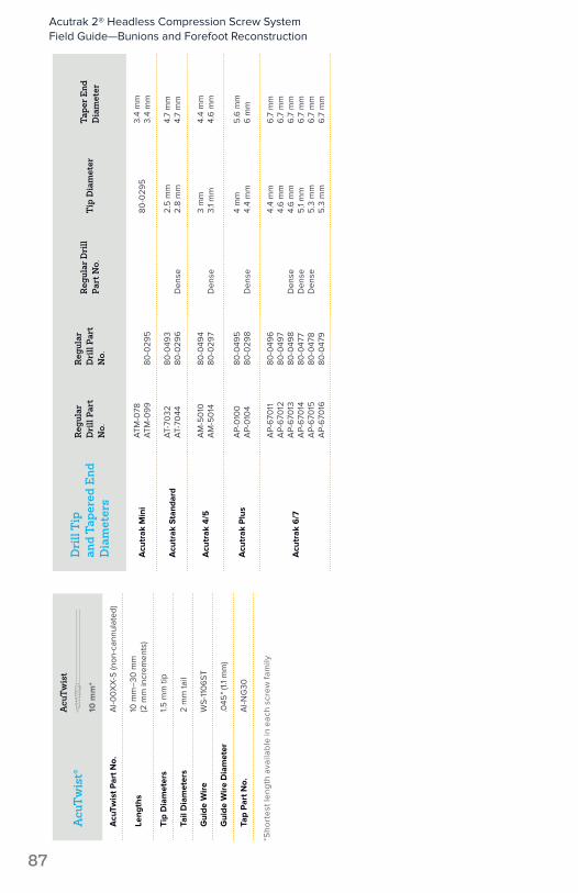
Acu
Twis
t®
Acu
Twis
t
10 m
m*
Acu
Twis
t Par
t No.
AI-0
0X
X-S
(non
-can
nula
ted)
Leng
ths
10 m
m–
30 m
m
(2 m
m in
crem
ents
)
Tip
Dia
met
ers
1.5 m
m ti
p
Tail
Dia
met
ers
2 m
m ta
il
Gui
de W
ire
WS-
110
6ST
Gui
de W
ire
Dia
met
er.0
45"
(1.1
mm
)
Tap
Par
t No.
AI-N
G30
Dri
ll T
ip
and
Tape
red
End
D
iam
eter
s
Reg
ular
D
rill
Part
N
o.
Reg
ular
D
rill
Part
N
o.
Reg
ular
Dri
ll Pa
rt N
o.T
ip D
iam
eter
Tape
r End
D
iam
eter
Acu
trak
Min
iA
TM-0
78A
TM-0
99
80-0
295
80-0
295
3.4
mm
3.4
mm
Acu
trak
Sta
ndar
dA
T-70
32A
T-70
4480
-049
380
-029
6D
ense
2.5
mm
2.8
mm
4.7
mm
4.7
mm
Acu
trak
4/5
AM
-50
10A
M-5
014
80-0
494
80-0
297
Den
se3
mm
3.1
mm
4.4
mm
4.6
mm
Acu
trak
Plu
sA
P-0
100
AP-
010
480
-049
580
-029
8D
ense
4 m
m4.
4 m
m5
.6 m
m6
mm
Acu
trak
6/7
AP-
670
11A
P-6
7012
AP-
670
13A
P-6
7014
AP-
670
15A
P-6
7016
80-0
496
80-0
497
80-0
498
80-0
477
80-0
478
80-0
479
Den
seD
ense
Den
se
4.4
mm
4.6
mm
4.6
mm
5.1
mm
5.3
mm
5.3
mm
6.7
mm
6.7
mm
6.7
mm
6.7
mm
6.7
mm
6.7
mm
*Sho
rtes
t len
gth
ava
ilab
le in
eac
h sc
rew
fam
ily
Acutrak 2® Headless Compression Screw System Field Guide—Bunions and Forefoot Reconstruction
87

These materials contain information about products that may or may not be available in any particular country or may be available under different trademarks in different countries. The products may be approved or cleared by governmental regulatory organizations for sale or use with different indications or restrictions in different countries. Products may not be approved for use in all countries. Nothing contained on these materials should be construed as a promotion or solicitation for any product or for the use of any product in a particular way which is not authorized under the laws and regulations of the country where the reader is located. Specific questions physicians may have about the availability and use of the products described on these materials should be directed to their particular local sales representative. Specific questions patients may have about the use of the products described in these materials or the appropriateness for their own conditions should be directed to their own physician.
Acumed®, Acutrak®, Acutrak 2®, and AcuTwist® are registered trademarks of Acumed LLC
Acumed Headquarters5885 NW Cornelius Pass RoadHillsboro, OR 97124 Office: +1.888.627.9957Office: +1.503.627.9957 Fax: +1.503.520.9618 www.acumed.net
SPF10-09-C | Effective: 2016/06 | © 2016 Acumed® LLC