ad-a257 729 - defense technical information center 729 4 structured analysis lsa task 303 evaluation...
TRANSCRIPT

AD-A257 729 4
STRUCTURED ANALYSISLSA TASK 303
EVALUATION OF ALTERNATIVES& TRADE-OFF ANALYSIS
SUBTASK 303.2.7LEVEL OF REPAIR ANALYSIS
APJ 966-210
MILITAR1St SCIENTIFICRESEARCH
92-287790 3 4l I 1]Ii!I ! I l

SECURITY CLASSIFICATION OF THIS PAGE
Form ApprovedREPORT DOCUMENTATION PAGE OMB No. 0704-0188
la. REPORT SECURITY CLASSIFICATION lb. RESTRICTIVE MARKINGSUNCLASSIFIED
2a. SECURITY CLASSIFICATION AUTHORITY 3. DISTRIBUTION /AVAILABILITY OF REPORT
2b. DECLASSIFICATION /DOWNGRADING SCHEDULE UNLIMITED
4. PERFORMING ORGANIZATION REPORT NUMBER(S) 5. MONITORING ORGANIZATION REPORT NUMBER(S)
6a. NAME OF PERFORMING ORGANIZATION 6b. OFFICE SYMBOL 7a. NAME OF MONITORING ORGANIZATION(If applicable)
AMCCOM, Army AMSMC-MAE-EA6c. ADDRESS (City, State, and ZIP Code) 7b. ADDRESS (City, State, and ZIP Code)
Rock Island ArsenalRock Island, IL 61299-6000
8a. NAME OF FUNDING/SPONSORING 8b. OFFICE SYMBOL 9. PROCUREMENT INSTRUMENT IDENTIFICATION NUMBERORGANIZATION (If applicable)
8c. ADDRESS (City, State, and ZIP Code) 10. SOURCE OF FUNDING NUMBERS
PROGRAM PROJECT TASK WORK UNITELEMENT NO. NO. NO. jACCESSION NO.
11. TITLE (Include Security Classification) Structured Analysis of the Logistic Support Analysis(LSA) Task, Evaluation of Alternatives and Trade-Off Analysis, Subtask303.2.7, "Level of Repair Analysis", (APJ 966-210).
12. PERSONAL AUTHOR(S)DULCOS, RONALD SHEPHERD, NED kmk
13a. TYPE OF REPORT 13b. TIME COVERED 14. DATE OF REPORT (Year, Month, Day) 15. PAGE COUNTFINAL FROM TO IAugust 198,8 165
16. SUPPLEMENTARY NOTATION
17. COSATI CODES 18. SUBJECT TERMS (Continue on reverse if necessary and identify by block number)
FIELD GROUP SUB-GROUP STRUCTURED ANALYSIS, LOGISTIC SUPPORT ANALYSIS,LSA, PROCESSES, DATA FLOWS, DATA STORES, EXTERNALENTITIES, PROCESS FLOWS, INTEGRATED LOGISTIC over
19, ABSTRACT (Continue on reverse if necessary and identify by block number)
This report is one of a series presenting the Structured Analysis for theLogistic Support Analysis (LSA) Task and the Integrated Logistic Support(ILS) Element. Included is the System Analysis for the LSA Subtask 303.2.7,"Repair Level Analysis (RLA)" (sometimes referred to as "Level Of RepairAnalysis (LORA)"), with the corresponding description of the processes, dataflows, data stores, external entities involved on each. An overview of theStructured Analysis and its place in the overall systems development processis also presented, as well as a guide to the overall RLA process of the LSATask analysis procedures, and a brief working description of the StructuredSystems Analysis fundamentals.
20. DISTRIBUTION /AVAILABILITY OF ABSTRACT 21. ABSTRACT SECURITY CLASSIFICATION•:UJNCLASSIFIED/UNLIMITED 0 SAME AS RPT. 0 DTIC USERS UNCLASSIFIED
22a. NAME OF RESPONSIBLE INDIVIDUAL 22b. TELEPHONE (Include Area Code) I 22c. OFFICE SYMBOLNED SHEPHERD (309) 782-2479 AMSMC-MAE-EA
DD Form 1473, JUN 86 Previous editions are obsolete. SECURITY CLASSIFICATION OF THIS PAGE
18. SUBJECT TERMS - continued: ' 4
SUPPORT , OVERALL SYSTEMS DEVELOPMENT PROCESS, REPAIR LEVEL ANALYSIS,RLA, LEVEL OF REPAIR ANALYSIS, LORA.
I
APJ 966-210
STRUCTURED ANALYSISLSA TASK 303
EVALUATION OF ALTERNATIVES& TRADE-OFF ANALYSIS
SUBTASK 303.2.7LEVEL OF REPAIR ANALYSIS Ace,•Q bor /
zsrrV . 13 C Eliunder ........ El
CONTRACT DAAA21-86-D-00 2 5
for
HQ, US AMCCOMINTEGRATED LOGISTIC SUPPORT OFFICE
AMSMC-LSPROCK ISLAND, IL
AMERICAN POWER JET COMPANY
RIDGEFIELD, NJ FALLS CHURCH, VA
FALLSTON, MD FT. EUSTIS, VA
AUGUST 1988
FOREWORD
APJ, under contract to HQs, AMCCOM, has initiated theautomation of the LSA Tasks (MIL-STD-1388-1) and theassessment of the ILS elements (AR 700-127). A major goal isto unify military and contractor approach to the performanceof ILS and LSA.
Detailed to meet all requirements of ILS and LSA, theautomated process will continue to provide the flexibility inselecting tasks and elements to be addressed at each lifecycle stage. A major advantage of this approach is to insurethat application of each task element is consistent withprescribed Army policies and procedures.
This report is one of a series presenting the StructuredAnalysis of each LSA Task and ILS Element. StructuredAnalysis comprises a description of the process beingautomated in terms which facilitate system design andsubsequent programming. It is increasingly the preferredapproach in both industry and Government.
This Technical Note reports on the Data Flow Diagrams(DFDs) of LSA Task 303.2.7, "Repair Level Analysis (RLA)"(sometimes referred to as "Level Of Repair Analysis (LORA)")and provides definitions of the processes, data flows, datastores, and external entities involved on each DFD (Annexes Aand B). The report provides an overview of the LSA Taskanalysis procedures and a guide to the overall RLA process.
To view this work in context, this report also presents abrief overview of Structured Analysis and its place in theoverall systems development process. Additionally, Annex Cprovides a brief working description of the Structured SystemsAnalysis fundamentals. The overview and certain portions ofthe introductory text are repeated verbatim in every report inthis series so that each one can stand alone.

STRUCTURED ANALYSIS - LSA SUBTASK 303.2.7RAPAIR LEVEL ANALYSIS
TABLE OF CONTENTS
TITLE PAGEPurpose .............................. 1Background. ....... ...... .... .... ...... 1
LSA Subtask 303.2.7 Description ...... 3Approach ............................ 5Structured Analysis and Design....... 6LSA Subtask 303.2.7 Data FlowDiagrams ............................ 9
ANNEX A:LSA Subtask 303.2.7 - RepairLevel Analysis (RLA)Description ......................... A-1
ANNEX B:Subtask 303.2.7 - Data Flow Diagramsand Data Dictionary ................. B-1
ANNEX C:Structured Systems Analysis -Fundarfentals ..... C-1
GLOSSARY ........... . ........... . ... G-1
LIST OF FIGURES
FGRNO TITLE PAGE
1 Structured Analysis andStructured Systems DesignOrganization .............. 8
2 Standard DFD SymbolDefinitions ............... 11
iii
STRUCTURED ANALYSIS - LSA SUBTASK 303.2.7
RAPAIR LEVEL ANALYSIS
INTRODUCTION
PURPOSE
The purpose of this report series is to present the
results of the APJ efforts under Contract DAAA21-86-D-0025 for
coordination with the AMCCOM Program Manager prior to in-depth
structured design of ILS and LSA functions and processes.
"Repair Level Analysis (RLA)" (LSA Subtask 303.2.7) is
addressed in this report.
BACKGROUND
The Department of the Army has a requirement for
management control over contractor and Government agency
response to the requirements of AR 700-127, "Integrated
Logistic Support", and MIL-STD-1388-1, "Logistic Support
Analysis". HQs AMCCOM has initiated action to structure
each of the LSA tasks, the assessment of each ILS element, the
form of the results, and the detailed processes to insure
consistency with current Army policies, procedures, and
techniques.

This approach (undertaken by AMCCOM and APJ) will insure
uniformity in efforts and products, reproducibility of
analyses, and a well-defined structure which can be
coordinated among all participants in the logistic process to
arrive at common understanding and procedures.
SCOPE
This report summarizes the results of the
Structured/Analysis of the Repair Level Analysis (RLA), LSA
Subtask 303.2.7 and presents the associated Data Flow Diagrams
(DFDs) developed from the Structured Analysis. The portions
of the Data Dictionary relating to labels, names,
descriptions, processes, data flows, data stores, and external
entities are included in their present degree of
completeness. (The Data Dictionary is a "living document"
that evolves through the analysis and design process).
To place this work in context, this report presents a
brief overview of Structured Analysis and its place in the
overall systems design process to assist the reader who may
not be fully briefed on the symbols and conventions used. It
is supported by Annex C, which defines each element in
structured analysis, and a glossary.
2
LSA SUBTASK 303.2.7 DESCRIPTION
LSA Subtask 303.2.7 concerns the development of a Repair
Level Analysis (RLA) for a specific equipment or system and
all of its major assemblies, subassemblies, and parts.
The Repair Level Analysis (RLA) is a decision-making
process which determines the most cost-effective actions
dealing with a failed item. The decisions that are required
include whether to repair the failed equipment, assembles,
subassemblies, or parts or to discard them and purchase
replacements. If the decision is to repair, then a further
decision must be made regarding the echelon at which each
maintenance function should be performed.
To assist in making these decisions, two computer programs
have been made available: The Interactive Palman Model (IPM)
and the Optimum'Supply And Maintenance Model (OSAMM).
The Palman Model evaluates the breakeven purchase cost
between a repair and discard concept. The program calculates
the breakeven point based on various cost factors impacted by
the range of expected deployments. If the actual or expected
cost of procuring an item exceeds the model output, the
assembly is considered a candidate for repair; if the
procuring cost is less, then discard should be considered.
3
The evaluation performed by the model provides the analyst
with the following:
- A table of values for breakeven cost vs. number of
end items
- An analysis of repair policy cost per failure with
breakdown of the elements and their percentage
contribution to the overall cost (reveals cost
"drivers")
- A sensitivity analysis to isolate critical,
significantly impacting decision variables.
The OSAMM aids in determining at which maintenance level
(organization, intermediate forward, intermediate rear, or
depot) various repair actions should be performed. The two
major factors influencing the repair level decision are
maintenance and supply requirements. Maintenance requirements
include test equipments and specially trained repairmen that
must be deployed to support repair. Supply is concerned with
the placement of spares in the field to achieve the
operational readiness objective. The OSAMM determines the
optimal maintenance/support task distribution.
The RLA task definitions from MIL-STD 1388-lA are
presented as Annex A.
4
APPROACH
The APJ approach to structured design of the LSA is:
1. Scope the process defined in MIL-STD-1388-IA inthe context of the other LSA tasks.
2. Review the guidance provided in AMC PAM 700-11,"Logistics Support Analysis Review Team Guide".
3. Review the applicable Data Item Descriptions(DIDs) from the Acquisition Management Systems and DataRequirements Control List (AMSDL) published by the Departmentof Defense.
4. Review all source documents referenced in theAMSDL as applicable to the referenced DIDs of interest.
5. Apply staff experience in logistics supportanalysis to assure that the intent of the task has beenaddressed.
6. Validate results in discussions with Armyactivities and personnel directly involved in the applicableor related LSA tasks.
The Structured Analysis and preparation of Data Flow
Diagrams (DFDs) were further assisted by the application of
Structured Analysis software. Licensed by Index Technology
Corporation, Excelerator provides for automated tracking of
names, labels, descriptions, multiple levels of detail in the
data flow diagrams, and industry standards in symbols and
diagramming practices.
Following completion of the draft DFDs, the diagrams and
data dictionary were made available to working Army
logisticians currently (or recently) directly involved in the
5
application of the same LSA tasks in current Army development
programs. Comments were solicited relative to the logic of
the processes described, the scope and details of the
indicated approaches, and the outputs implied by the LSA task
requirements.
Draft products were well received by the external
reviewers, and requests have been made for copies of the DFDs
for in-house use in organizing ILS and LSA efforts. Comment
was also received that the DFDs will be a useful training tool
for apprentice logisticians, since they provide an overall
picture of the total task and a uniform approach to its
fulfillment.
STRUCTURED ANALYSIS AND DESIGN
Structured Analysis and Structured Systems Design evolved
from the need to define and demonstrate the underlying
logical functions and requirements of large systems. The
concept of Structured Analysis involves building a logical
(non-physical) model of a system, using graphic techniques
which enable users, analysts, and designers to get a clear and
common picture of the system and how its parts fit together to
meet the user's needs. It is followed by structured design,
and then by programming, and test and validation. Annex C
provides a brief description and guide to the fundamentals of
a Structured Systems Analysis.
6

The Structured Analysis and Structured Systems Design
process, sometimes referred to as "Structured Systems Analysis
and Design (SSAD)", is well documented and widely utilized in
Government and industry.
As stated in "The Practical Guide to Structured Systems
Design" (Meilir Page-Jones, Prentice-Hall, Englewood Cliffs,
NJ, 1980):
... "Structured Design is disciplined approach to computersystem design, an activity that in the past -has beennotoriously haphazard and fraught with problems.
"I. Structured Design allows the form of the problem toguide the form of the solution.
"2. Structured Design seeks to conquer the complexity oflarge systems by means of partitioning the system into "blackboxes," and by organizing the black boxes into hierarchiessuitable for computer implementation.
"3. Structured Design uses tools, especially graphicones, to render systems readily understandable.
`4. Structured Design offers a set of strategies fordeveloping a design solution from a well defined statement ofa problem.
"5. Structured Design offers a set of criteria forevaluating the quality of a given design solution with respectto the problem to be solved.
"Structured Design produces systems that are easy tounderstand, reliable, flexible, long lasting, smoothlydeveloped, and efficient to operate - and that WORK...."
The organization of Structured Analysis and its
relationship to Structured System Design is shown on Figure 1.
7
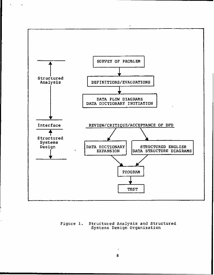
¶ SURVEY OF PROBLEM
StructuredAnalysis DEFINITIONS/EVALUATIONS
DATA FLOW DIAGRAMSDATA DICTIONARY INITIATION
Interface REVIEW/CRITIQUE/ACCEPTANCE OF DFD
StructuredSystemsDesign DATA DICTIONARY STRUCTURED ENGLISH
SEXPA NSION DATA STRUCTURE DIAG RAMS
PROGRAM
S-TEST
Figure 1. Structured Analysis and StructuredSystems Design Organization
8
LSA SUBTASK 303.2.7 - DATA FLOW DIAGRAMS
The Data Flow Diagram is a tool that shows flow of data,
i.e., data flows from sources and is processed by activities
to produce intermediate or final products.
The DFD provides a useful and meaningful partitioning of a
system from the viewpoint of identification and separation of
all functions, actions, or processes so that each can be
introduced, changed, added, or deleted with minimal disruption
of the overall program, i.e., it emphasizes the underlying
concept of modularity and identifiable transformations of data
into actionable products.,
A series of four (4) DFDs have been developed to structure
the RLA LSA subtasks:
1. 303.2.7 RLA Overview
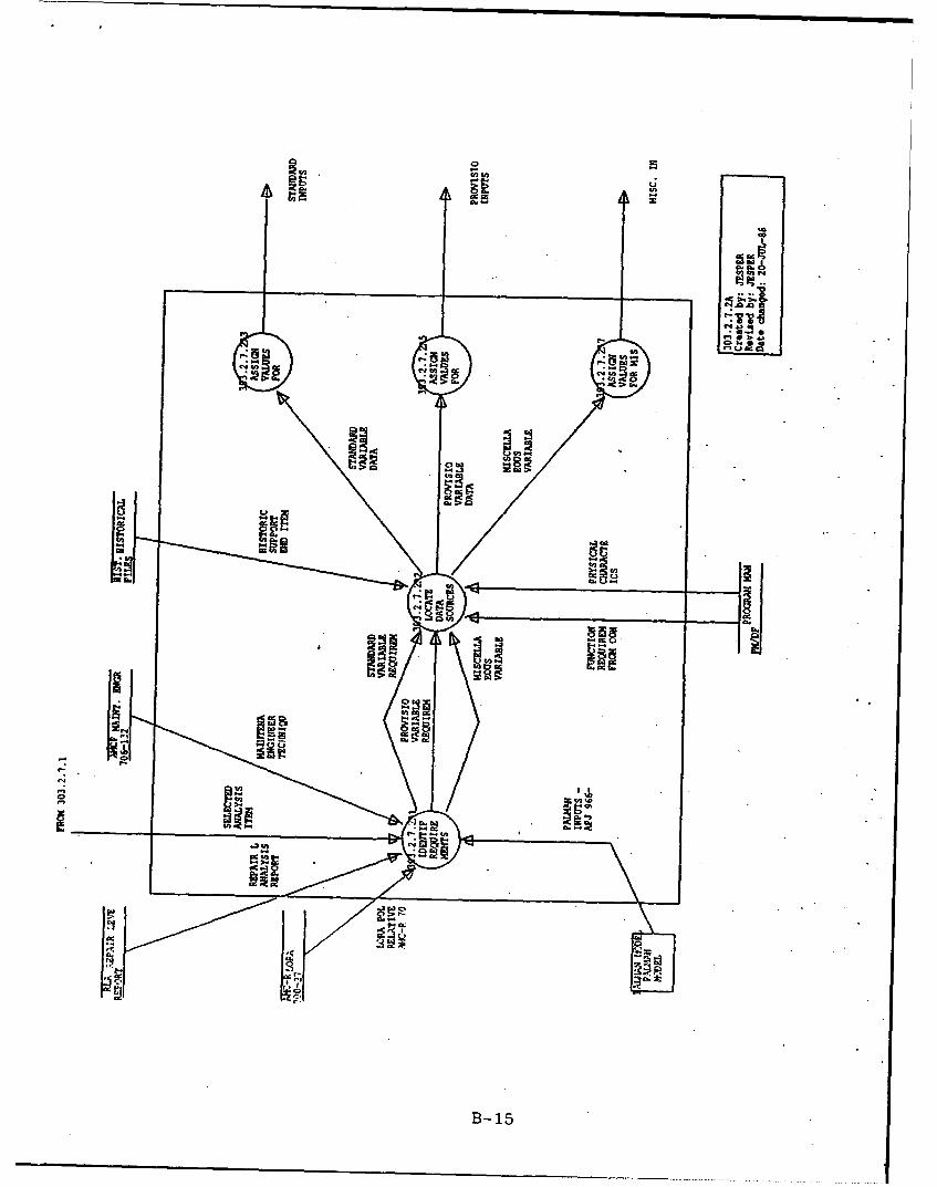
2. 303.2.7.2A Preparation of Palman Database
3. 303.2.7.3A Application of Palman Model
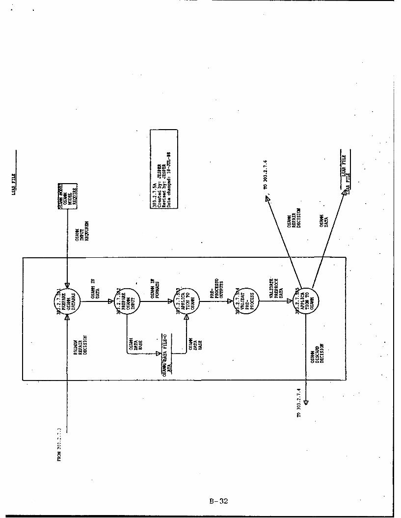
4. 303.2.7.5A Application of OSAMM
Each DFD makes reference to the basic LSA task it
addresses through the identification number assigned in the
lower right hand box, as well as the level of indenture
(explosion) of the DFD. For example, the first or top level
DFD, "303.2.7", refers to the paragraph in MIL-STD-1388-IA
which describes the task. One of the processes (bubbles) on
the top level diagram (303.2.7.2) is expanded and identified
as "303.2.7.2A", (Alpha "A" identifies the expansion).
9

The Alpha codes indicate the level of indenture or
explosion below the top level, e.g.,:
Top Level ..................... LSA DFD 303.2.7
First Indenture .......... LSA DFD 303.2.7.2A
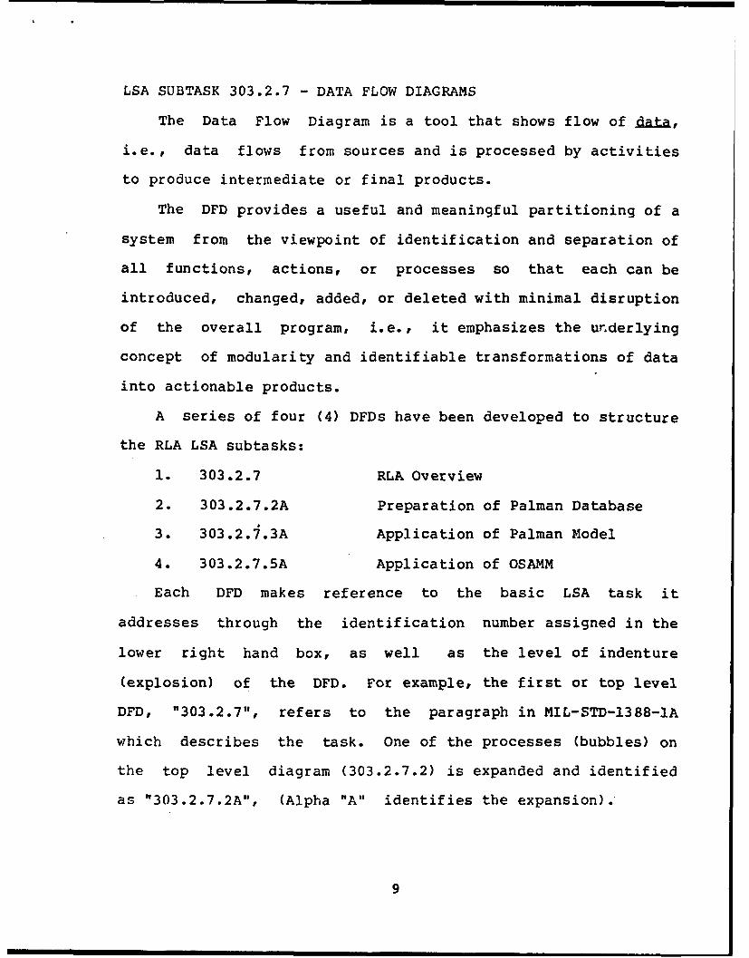
Four standard symbols are used in the DFD drawing (see
Figure 2).
A copy of each DFD is presented in Annex B, accompanied
by the Data Dictionary process elements. Each entry made in
the DFDs has a corresponding entry in the Data Dictionary,
immediately following each of the DFDs.
This Technical Note presents the Data Dictionary entries
necessary for the coordination of the overall concept and
details of the processes. These include data flow
identifications, process, external entities and data store
descriptions are provided. As noted above, they will continue
to evolve and be expanded in the System Design phase.
As the DFDs progress through Structured System Design, the
Data Dictionary will continue to be expanded and completed.
Since they are working documents rather than final
submissions, only minimum effort has been devoted to editorial
niceties, e.g., spelling, typography, etc.
10
REPRESENTS A PROCESS, FUNCTION,OR ACTION
REPRESENTS A DATA STORE OR ADATA FILE -. OFTEN IDENTIFIED ASREPOSITORY OF INFORMATION OF ASPECIFIC TYPE
REPRESENTS A DATA ELEMENT FLOWINDICATING OUTPUT FROM ONEPROCESS AND INPUT TO ANOTHERPROCESS
REPRESENTS AN EXTERNAL ENTITY -AN ACTIVITY NOT A PART OF THESYSTEM/PROCESS BEING MODELED.
Figure 2. STANDARD DFD SYMBOL DEFINITIONS
11
ANNEX A
LSA SUBTASK 303.2.7
REPAIR LEVEL ANALYSIS
(RLA)

ANNEX ALSA TASK 303
EVALUATION OF ALTERNATIVES AND TRADEOFF ANALYSIS I/
303.1 PURPOSE: To determine the preferred support systemalternative(s) for each system/equipment alternative and toparticipate in alternative system tradeoffs to determine thebest approach (support, design, and operation) which satisfiesthe need with the best balance between cost, schedule,performance, readiness, and supportability.
303.2 TASK DESCRIPTION:
303.2.7 - Conduct repair level analysis (RLA) commensuratewith the level of design, operation, and support dataavailable.
I/ Abstracted verbatim from MIL-STD-1388-lA, April 11, 1983,Pages 36-37.
A-1
ANNEX B
SUBTASK 303.2.7
DATA FLOW DIAGRAMS AND DATA DICTIONARY

ac :
AI
B-1.
DATE: 26-AUG-88 APJ PROJECT 966 PAGE 1
TIME: 17:09 TASK 303.2.7 PROCESSES EXCELERATOR 1.8
Name Label Description
303.2.7.1 SELECT AP- ACRONYMS:
PROPRIATE OSAMM - Optimum Supply And Maintenance Model
END ITEM, LOR - Level Of Repair
COMPONENT, UBS - Work Breakdown Structure
OR MODULE LRU - Lowest Repairable Unit
PROCESS:
The process of developing an End Item LOR decision for Army
materiel follows two serial processes:
1. First, a decision is made for Repair or Discard/Replac, with the
application of the Palman modal.2. If a decision is made for repair, a further decision is made for
the optimum maintenance level for the repair to be effected. This
task is accomplished with the application of the OSAM model.
These decisions are made for all three indenture levels of the
MUS from the top down. The levels of the end item are components,
modules, and the LRU. If a discard decision is made at any level for any
branches of the WBS, all lower level decisions in the same branch would
not be meaningful.This specific process in iterative in that the initial selection
is the top level item (such as end item). Next iteration (or selection)
will be the second indenture components assuming that the end item
decision was to repair. The third iteration would be at the module
level for each component rated as repairable. This iterative process
continues until each potentially repairable item has been considered.DATA SOURCES:
Interactive Palman Model User's Guide
OSAM4M User's Guide Version 2.0
1-2

DATE: 26-AUG-88 APJ PROJECT 966 PAGE 2
TIME: 17:09 TASK 303.2.7 PROCESSES EICELEERATOR 1.8
Name Label Description
303.2.7.2 PREPARE ACRONYMS:
PALMAN IPM - Interactive Palman Model
DATABASE DA - Department of the Army
PAM - Pamphlet
PROCESS:
The IPM as described in DA PAM 700-4, is an interactive tool to
assess repair versus discard decisions and perform sensitivities on key
factors.
The 1PM requires the development/formatting of three sts of
variables:
1. 14 standard variables
2. 13 provisioning variables
3. 13 miscellaneous variables
The specific data elements are listed under the three data flows
into the Application of the Palman model. These variables may be
arranged by:
1. supply
2. Test equipment and facilities
3. Personnel
4. Maintenance
5. End item
6. Initial provisioning
The key sources of data for the elements are:
1. Functional requirements from concept development and documentation
2. Physical characteristics from engineering reports
3. Other types of information from historical data bases
The data inputs for the Palman Model must relate to the specific
item (at the appropriate indenture levels) selected in subtask 303.2.7.1
and be prepared in a form which can be readily applied to the computer
input requirements. These data formats are set forth in the Palman
documentation, "Interactive Palman Model User's Guide, June 21, 1984."
There are two types of data files which are used by the Palman
program: Standard Input Data Files and General Input Data Files. The
Standard file, which may be created by the program, is used to
initialize a new analysis. After the standard data have been entered,
either by keyboard or from the standard file, then the peculiar data are
entered by keyboard. The program now prepares the general file (s).
To view the process of the Preparation of the Palman Database in
more detail, explode this process to Subtaak 303.2.7.2A.
DATA SOURCES:DA PAM 700-4, Logistic Support Analysis Techniques Guide, March
31, 1987
Interactive Palman Model User's Guide, June 21, 1984
Palman Model User Guide, August 14, 1987
B-3

DATE: 26-AUG-88 APJ PROJECT 966 PAGE 3
TIME: 17:09 TASK 303.2.7 PROCESSES EXCELERATOR 1.8
Name Label Description
303.2.7.3 APPLICA- ACRONYMS :
TION OF LRU - Lowest Repairable Unit
PALMAN WEBS - Work Breakdown Structure
MODEL R/D - Repair/DiscardPROCESS:
With the application of the Palman model, a repair or
discard/replace decision can be made on the end item and for each of
the lower level items (components, modules, LRU's, etc.) as set forth
in the WBS.
The Palman program calculates R/D break-even cost over a range of
expected deployment densities given the standard, provisioning, and
miscellaneous inputs. In this analysis, if the life cycle cost of the
end item exceeds the break-oven cost value, the end item should be
repaired. Similarly, when the life cycle cost of the end item is less
than the break-even point, that item should be discarded.
The program also outputs the cost and percentage cost contribution
of individual variables to repair cost.
After making the R/D analysis, the Palman program can be used to
perform a sensitivity analysis. This analysis reveals the amount that
the various model parameters that are selected can be in error without
changing the overall R/D decision. The parameters with the highestpercentage cost contribution are usually selected for sensitivity
analyses.
For a detailed description of the necessary procedures to apply the
model and run it, explode this process to Subtask 303.2.7.3k.
DATA SOURCES:
Interactive Palman Model User's Guide, June 21, 1984
Palman User's Manual, August 14, 1987
303.2.7.4 PREPARE ACRONYMS:
SUMMARY
REPORT - PROCESS:
DISCARDS Preparation of a sumnmary report of those items, components, or
modules of the end item for which the Palman Model has indicated
discard decision - that is, it would be economically beneficial to
discard and replace with new like items rather than provide for the and
item' s repair.
DATA SOURCES:
303.2.7.5 APPLICA- ACRONYMS :
TION OF OSANM - Optimum Supply And Maintenance Model
OSAIO4 LORA - Level Of Repair Analysis
PROCESS
PROCESS:
The OSAMM is applied to simultaneously optimize supply and
maintenance policies while achieving a given operational availability
target.
To see the OSAMM in more detail, explode this process to Subtask
303.2.7.5A.
DATA SOURCE:
OSA•M Program
B-4
DATE: 26-AUG-SB APJ PROJECT 966 PAGE 4
TIME: 17:09 TASK 303.2.7 PROCESSES EXCELERATOR 1.8
Name Label Descript ion
303.2.7.6 PREPARE ACRONYMS:
LEVEL OF OSAMM - Optimum Supply And Maintenance Model
REPAIR
REPORT PROCESS:
The Level of Repair Report contains the results of the application
of the Palman and OSAMM models to the equipment/system and itscomplete Work Breakdown Structure. This report contain.
all the recommendations and supporting rationale for oystem/equipment
maintenance and logistics support planning decisions.
DATA SOURCES:
B-5
DATE: 26-AUG-68 APJ PROJECT 966 PAGE I
TIME: 17:12 TASK 303.2.7 DATA FLOWS EXCELERATOR 1.B
Name Label Description
AMCP 706-132 MAINTENANCE Maintenance Engineering Techniques are the activities of equipment
ENGINEERING maintenance which develop concepts, criteria, and technical
TECHNIQUES requirements durinn the conceptual and acquisition phases to be applied
and maintained in a current status during the operational phase to
assure timely and adequate economic maintenance support of weapons and
equipments.
DRAFT DRAFT RLA A draft report of the results of the equipment/system Level of
REPORT Repair Analysis in accordance with DI-R-3549A, DI-R-3549/R-117-2, or
DI-S-6169, the most appropriate for the specific analysis performed.
FUNC FUNCTIONAL Identification of the operations and support functions that must be
REQUIREMENTS performed for each system/equipment alternative under consideration andSELECTED then identification of the tasks that must be performed in order to
ITEM operate and maintain the now system/equipment in its intendeK
environment.
These functions shall be identified to a level connensurate with
design and operational scenario development, and shall include both
peacetime and wartime functions.
These data will be available from the Concept Formulation Package
which will include a Feasibility Study as well as Advance Product
Planning. The Feasibility Study from the Concept Formulation Package
will consist of a Needs Analysis, the System Operational Requiremeents,
and the System Maintenance Concept. Advance Product Planning is
concerned with Plans and specifications of the equipment/eystem.
HIST HISTORICAL Prior to the actual test and field use of the end item, it will be
SUPPORT DATA necessary to develop various reliability, maintainability, and
END ITEM availability parameters which are required to support the data base forLOGISTICAL application to the Palman Model. These quantifications of the
EQUIVALENTS availability parameters may be derived from an analysis of logistically
equivalent systems, operating in similar environmental and operating
conditions. These data will be extracted from the historical files and
used in the development of the model inputs for the end item and for
each of its lower indenture components, modules, or parts.
INIT INITIATING The initiating action would be the signed task order by APJ and
ACTION the HQ, AMCCOM contraction officer representative.
LORA POLICY LORA POLICY In the selection of the parameters for application to the Palman
RELATIVE TO Model, it will be necessary to transfer the policy and guidance ofAMC-R 700-27 AMC-R 700-27 to the analyst and programs assigned to the application of
the Palman Model to the end item and its lower indentures of the Work
Breakdown Structure.
LSAR INPUTS LSAR The data which are entered into the end item LSAR are made
INPUTS available for preparation of the report to be generated as item No. 1
from the Contract Data Requirements List. (DD Form 1423)
B-6
DATE: 26-AUG-88 APJ PROJECT 966 PAGE 2
TIME: 17:12 TASK 303.2.7 DATA FLOWS EXCELERATOR 1.8
Name Label Description
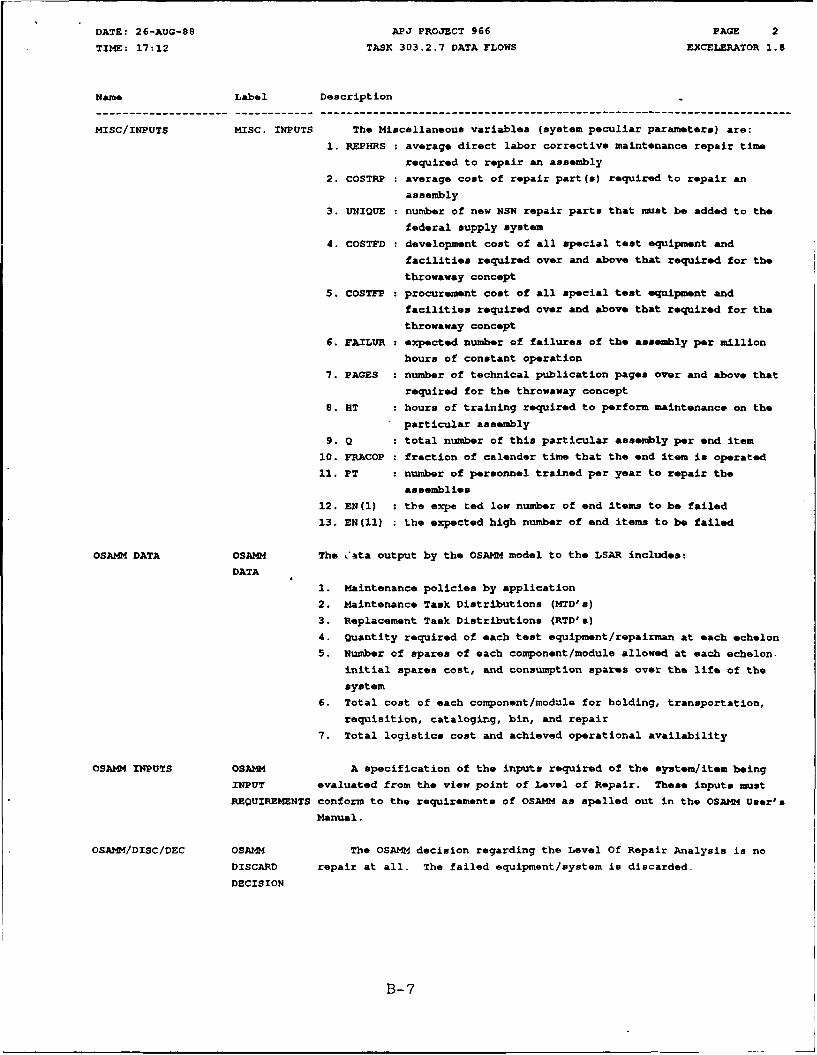
MISC/INPUTS MISC. INPUTS The Miscellaneous variables (system peculiar parameters) are:
1. REPHRS : average direct labor corrective maintenance repair time
required to repair an assembly
2. COSTRP : average cost of repair part(s) required to repair an
assembly
3. UNIQUE : number of new NSN repair parts that must be added to the
federal supply system
4. COSTFD : development cost of all special test equipment and
facilities required over and above that required for the
throwaway concept
5. COSTFP : procurement cost of all special test equipment and
facilities required over and above that required for the
throwaway concept
6. FAILUR : expected number of failures of the assembly per million
hours of constant operation
7. PAGES : number of technical publication pages over and above that
required for the throwaway concept
S. RT : hours of training required to perform maintenance on the
particular assembly
9. Q : total number of this particular assembly per end item
10. FRACOP : fraction of calender time that the end item is operated
11. PT : number of personnel trained per year to repair the
assemblies
12. EN(l) : the expe ted low number of end items to be failed
13. EN(11) the expected high number of end items to be failed
OSAMM DATA OSAMM The Cata output by the OSAM4 model to the LSAR includes:
DATA
1. Maintenance policies by application
2. Maintenance Task Distributions (MTD's)
3. Replacement Task Distributions (RTD's)
4. Quantity required of each test equipment/repairman at each echelon
5. Number of spares of each component/module allowed at each echelon-
initial spares cost, and consumption spares over the life of the
system
6. Total cost of each component/module for holding, transportation,
requisition, cataloging, bin, and repair
7. Total logistics cost and achieved operational availability
OSAMM INPUTS OSA)M A specification of the inputs required of the system/item being
INPUT evaluated from the view point of Level of Repair. These inputs must
REQUIREMENTS conform to the requirements of OSAMM as spelled out in the OSAMM User's
Manual.
OSAMM/DISC/DEC OSAMM The OSAI-4 decision regarding the Level Of Repair Analysis is no
DISCARD repair at all. The failed equipment/system is discarded.
DECISION
B-7
DATE: 26-AUG-88 APJ PROJECT 966 PAGE 3
TIME: 17:12 TASK 303.2.7 DATA FLOWS EXCELERATOR 1.8
Name Label Description
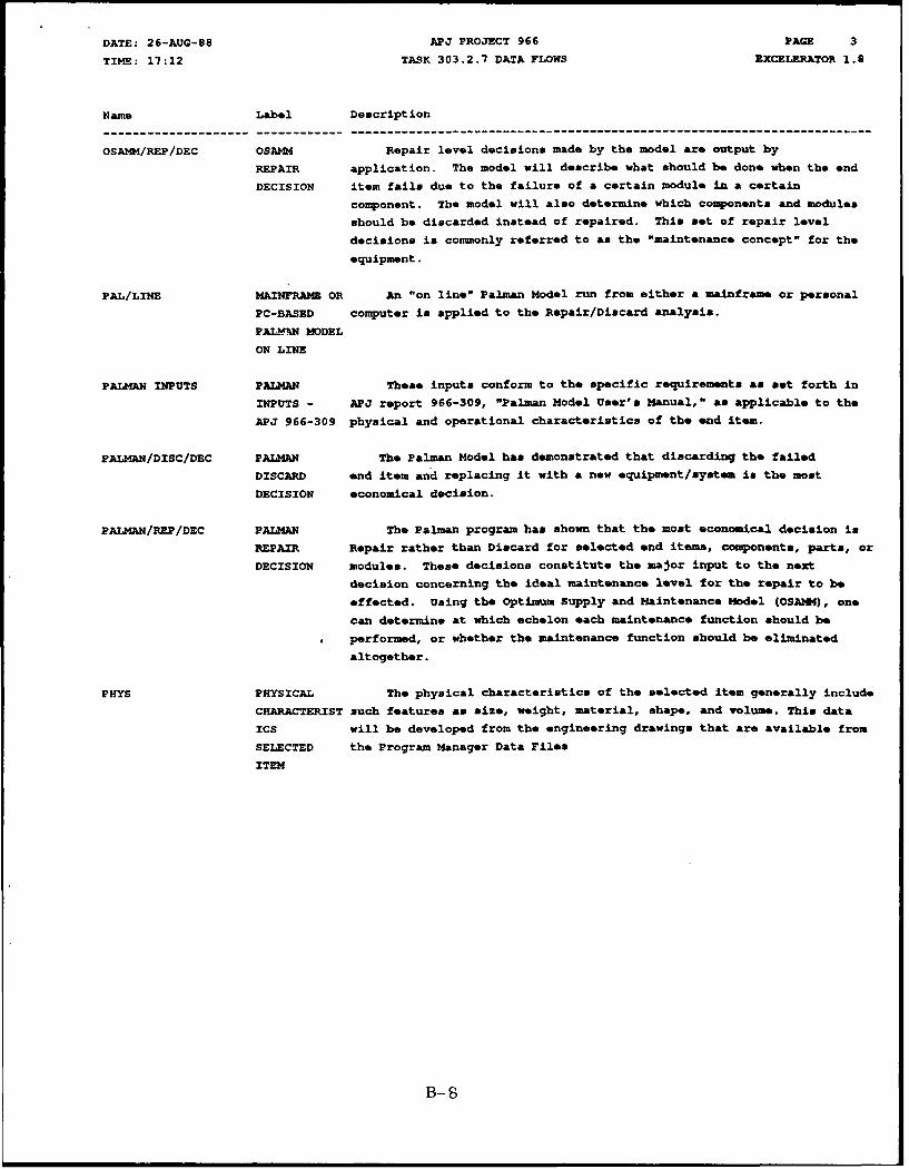
OSAM4/REP/DEC OSAMM Repair level decisions made by the model are output by
REPAIR application. The model will describe what should be done when the end
DECISION item fails due to the failure of a certain module in a certain
component. The model will also determine which components and modules
should be discarded instead of repaired. This set of repair level
decisions is commonly referred to as the "maintenance concept" for the
equipment.
PAL/LINE MAINFRAM OR An "on line" Palman Model run from either a mainframe or personal
PC-BASED computer is applied to the Repair/Discard analysis.
PAL!••IN MODEL
ON LINE
PALMAN INPUTS PALMAN These inputs conform to the specific requirements as set forth in
INPUTS - APJ report 966-309, "Palman Model User's Manual," as applicable to the
APJ 966-309 physical and operational characteristics of the end item.
PALMAN/DISC/DEC PALMAN The Palman Model has demonstrated that discarding the failed
DISCARD end item and replacing it with a new equipment/system is the most
DECISION economical decision.
PALMAN/REP/DEC PALMAN The Palman program has shown that the most economical decision is
REPAIR Repair rather than Discard for selected end items, components, parts, or
DECISION modules. These decisions constitute the major input to the next
decision concerning the ideal maintenance level for the repair to be
effected. Using the Optimum Supply and Maintenance Model (OSAZO), one
can determine at which echelon each maintenance function should be
performed, or whether the maintenance function should be eliminated
altogether.
PHYS PHYSICAL The physical characteristics of the selected item generally include
CHARACTERIST such features as size, weight, material, shape, and volume. This data
ICS will be developed from the engineering drawings that are available from
SELECTED the Program Manager Data Files
ITEM
B-S

DATE: 26-AUG-88 APJ PROJECT 966 PAGE 4
TIME: 17:12 TASK 303.2.7 DATA FLOWS EXCELERATOR 1.9
Name Label Description
PROV/INPUTS PROVISIONING The Provisioning variables (supply related parameters) are:
INPUTS
1. OST(1) : Order and Ship Time in days between equipment and Direct
Exchange (DX)
2. OST(2) : OST in days between DX to Maintenance Level Supply (MLS)
3. OST(3) : OST in days between MLS and Depot
4. OST(4) : OST in days between Depot and Factory
5. OST(5) : OST in days for parts to be obtained by maintenance
facility
6. TAT : Turn Around Time in days for assemblies at maintenance
facility
7. CKK Safety Stock Coefficient (decimal %), percent of stock
above demand to cover delays
8. RPNSTD Perecnt of repair parts that are non-standard, requiring
new NSN's
9. INIPA : Minimum number of days of authorized assembly stockage
10. INIEP : Minimum number of days of authorized parts stockage
11. DXN : Number of DX supply locations
12. CGN Number of Maintenance Level Supply locations
13. PNFAIL : Percent of non-operational failures due to obsolescence,
shelf life, etc.
RLA/RQMNTS REPAIR LEVEL DI-L-2085A states the requirements of a report which are to be
ANALYSIS addressed in the End Item Level of Repair Analysis. The specific
REPORT requirments are abstracted and forwarded to the process to establish the
REQUIREMENTS Palman database to insure that these requirements are met.
SELECT SELECTED * This data flow will represent the iteration of the selection
ANALYSIS of items for the Palman Model evaluation. The first selection will be
ITEM the equipment/system as an end item. Following iterations will include
major components, modules, and LRU as set forth in the WES.
B-9
DATE: 26-AUG-98 APJ PROJECT 966 PAGE 5
TIME: 17:12 TASK 303.2.7 DATA FLOWS EXCELERATOR 1.8
Name Label Description
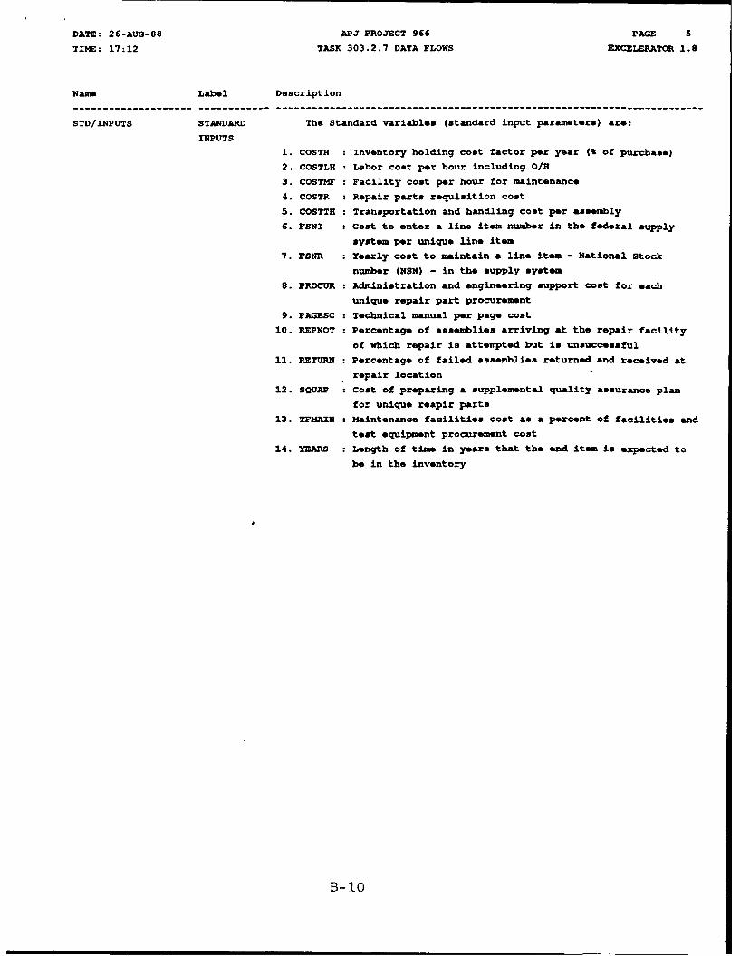
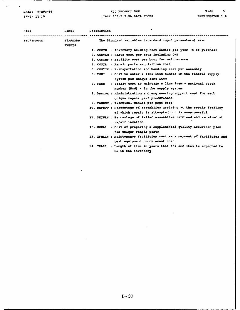
STD/INPUTS STANDARD The Standard variables (standard input parameters) are:
INPUTS
1. COSTH : Inventory holding cost factor per year (% of purchase)
2. COSTLH : Labor cost per hour including O/E
3. COSTMF : Facility cost per hour for maintenance
4. COSTR : Repair parts requisition cost
5. COSTTH : Transportation and handling cost per assembly
6. FSNI Cost to enter a line item number in the federal supply
system per unique line item
7. FSNR : Yearly cost to maintain a line item - National stock
number (NSN) - in the supply system
8. PROCUR : Administration and engineering support cost for each
unique repair part procurement
9. PAGESC : Technical manual per page cost
10. REPNOT • Percentage of assemblies arriving at the repair facility
of which repair is attempted but is unsuccessful
11. RETURN : Percentage of failed assemblies returned and received at
repair location
12. SQUAP : Cost of preparing a supplemental quality assurance plan
for unique reapir parts
13. TFMAIN : Maintenance facilities cost as a percent of facilities and
test equipment procurement cost
14. YEARS : Length of time in years that the end item is expected to
be in the inventory
B-10
DATE: 26-AUG-88 APJ PROJECT 966 PAGE 6
TIME: 17:12 TASK 303.2.7 DATA FLOWS EXCELERATOR 1.6
Name Label Descript ion
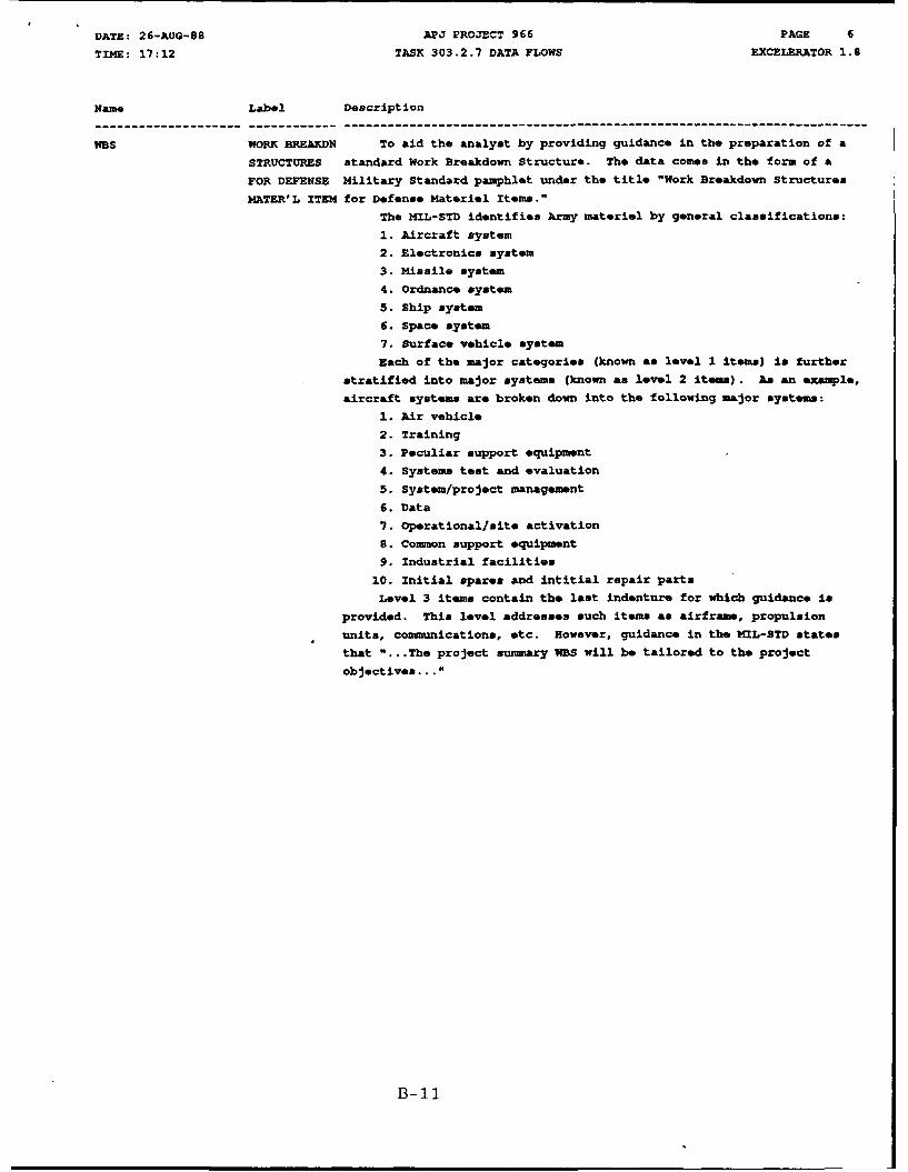
WBS WORK BREAKDN To aid the analyst by providing guidance in the preparation of a
STRUCTURES standard Work Breakdown Structure. The data comes in the form of a
FOR DEFENSE Military Standard pamphlet under the title "Work Breakdown Structures
MATER'L ITEM for Defense Materiel Items."
The MIL-STD identifies Army materiel by general classifications:
1. Aircraft system
2. Electronics system
3. Missile system
4. Ordnance system
5. Ship system
6. Space system7. surface vehicle system
Each of the major categories (known as level I items) is further
stratified into major systems (known as level 2 items). As an example,
aircraft systems are broken down into the following major systems:
1. Air vehicle
2. Training
3. Peculiar support equipment
4. Systems test and evaluation
5. System/project management
6. Data
7. Operational/site activation
S. Common support equipment
9. Industrial facilities
10. Initial spares and intitial repair parts
Level 3 items contain the last indenture for which guidance is
provided. This level addresses such items as airframe, propulsion
units, communications, etc. However, guidance in the MIL-STD states
that "...The project suzmmary WBS will be tailored to the project
objectives..."
B-il

DATE: 26-AUG-88 APJ PROJECT 966 PAGE I
TIME: 17:13 TASK 303.2.7 DATA STORES EXCELERATOR 1.8
Name Label Description
AMC-R 700-27 LORA AMC-R 700-27, "Level of Repair Analysis (LORA) Program," prepared
by HEQ, U.S. Army Materiel Command (March '85) establishes AMC
objectives and policies, and assigns responsibilities for a LORA
program throughout all phases of a materiel systems life cycle.
Appendix C to this AMC regulation establishes policy on level of
repair models. It identifies the Palman model as applicable to specific
aspects of repair analysis and can be used for the repair/discard
decision. OSAMM is considered applicable to system/end item analysis.
AMCP 706-132 MAINT. ENGR. AMCP 706-132 will provide the maintenance engineering techniques
TECHNIQUES applicable to the development of the variables for application of the
Palman Model, the end item, and its major components, items, and parts.
HIST. FILES HISTORICAL This data store contains data previously acquired on the
FILES system/equipment under investigation or some similar system and may
address the following areas:
1. Reliability Data
2. Failure Rate Data
3. Spares and Spares Funding Data
The availability, accuracy, and relevancy of experience of
historical databases on similar existing systems is crucial for
accomplishment of the task in question, namely Repair Level Analysis.
LSAR FILE LSAR FILE This file or records holding area contains:
1. The equipment/system LSA Task reports or their equivalent.
2. The equipment/system LSAR master records sheet information.
3. The equipment/system LSAR reports when system is automated.
It contains logistics data which can be used to assess the ILS
elements set forth in MIL-STD 1389-IA and conforms to the records/files
prescribed in MIL-STD 1388-2A.
RLA REPORT REPAIR LEVEL Data Item Descriptions DID-R-3549/R-117-2 and DID-S-6169 specify
ANALYSIS REPORT the type of detailed data required in a report on the Optimum Repair
Level of Analysis (ORLA). Although the DIDs leave the format of the
report to the discretion of the contractor, the data details required
as adequate to establish a baseline for the reassessment of the OQLA as
more detailed design data are obtained.
DID-R-3549A specifies the type of data required in a report of the
repair level analysis (RLA) reports. As noted for the DIDs above,
an extensive data base is required. In this case, the report requires a
rational for each action proposed, the numerical data used to determine
the level of repair, sensitivity analysis performed and the results,
rationale to support the RaM parameters used, interface considerations
used, and recommendations for updating planning factors for maintenance
and logistic support.
B-12

DATE: 9-AUG-08 APJ PROJECT 966 PAGE 1
Tite: 12:17 TASr 303.2.7 EXTERNAL ENTITIES EXCELERATOR 1.8
Name Label Description
APPROVAL APPROVAL Final approval and publication for distribution will be made by
AUTHORITY the HQ, AMCCOM technical representative or the contracting officer.
/PUBLISH-
ER
COHCEPT CONCEPT The Concept Development involves a Feasibility Study as well as
DEVELOP- Advance Product Planning. The Feasibility Study consists of a Needs
MENT Analysis, the System Operational Requirements, and the System
Maintenance Concept. Advance Product Planning is concerned with plans
and specifications of the equipment/system.
EDR ENGINEER- The Engineering Design Reports show the assembly and construction
ING of the equipment/system in question.
DESIGN
REPORTS
ENGR. ENGINEER- The Engineering Drawings show the physical characteristics of the
ING equipment/system in question.
DRAWINGS
MAINTAIN MAINTAIN- Maintainability Analysis Summary - Level of Repair Report
ABILITY
ANALYSIS This report yields the projected workload resulting from the
SUMMARY Failure Modes Effects and Criticality Analysis. The report details the
Level of Repair to he performed on an item for all maintenance levels.
It will also be used to review reliability and maintainability factors
for the repair time of an item.
(From DI-L-7177, LSA-053, MIL-STD-1388-2A)
OSAMM MODEL OSANM CECOM-TR-87-3, "Optimum Supply and Maintenance Model Release 2.0
MODEL User's Guide," is used to identify the specific inputs required for the
REQUIRE- equipment/system to run the repair level decision model.
MNTS
PALMAN MODEL A The Palman Model has been developed to evaluate the breakeven
MODEL purchase cost for a weapons system component or assembly and to let the
user make a decision to either repair the component/assembly or discard
it.
The operation and specification of the inputs required for the
Palman Model are described in the APJ Report 966-309, "Palman Model
User's Manual."
The Palman Model is written in FORTRAN IV so that is easily
portable to most computer systems with a keyboard, monitor, file
system, and printer.
B- 13
DATE: 9-AUG-S89 APJ PROJECT 966 PAGE 2
TIME: 12:17 TASK 303.2.7 EXTEPRAL ENTITIES EXCELERATOR 1.9
Name Label Description
-- ----------- ---------- -------------------------------------------------------------------------
PROGRAM MANAGER PROGRAM The Program Manager seeks to conduct a Repair Level Analysis
MANAGER commensurate with the level of design, operation, and support data
available.
For the Integrated Logistics Support Program associated with the
acquisition life cycle of system/equipment, a logistics support
analysis is to be made.
To decide whether the failed component should be either repaired or
replaced, the Interactive Palman Model (XPM) will be employed to
determine the most cost-effective action.
B-14
0
cn U)
C4
CC
~~PI
'4was5
DATE: 26-AUG-88 APJ PROJECT 966 PAGE 1TIME: 17:11 TASK 303.2.7.2A PROCESSES EXCELERATOR 1.8
Name Label Description
303.2.7.2A1 IDENTIFY ACRONYMS:
REQUIRE- MRSA - Materiel Readiness Support Activity
MENTS LSAT - Logistics Support Analysis Techniques
PROCESS:
Examine the parameters needed to run the Palman Model, and identify
the data needed to satisfy the input requirements.
DATA SOURCES:
Interactive Palman User's Guide, June 21, 1984
Technical Review and Analysis of Palman Repair vs. Discard Model,
IMSA LSAT 84-06
B- 16
DATE: 26-AUG-88 APJ PROJECT 966 PAGE 2
TIME: 17:11 TASK 303.2.7.2A PROCESSES EXCELERATOR 1.8
Name Label Description.
303.2.7.2A2 LOCATE ACRONYMS:
DATA LSA - Logistic Support Analysis
SOURCES - RIPCUS - Retail Inventory Cost Parameter Update Study
STANDARD CCSSOI - Commodity Command Standard System Operating Instructions
DATA l - Materiel Management Decision
LPL - Logistic Parameters Library
POC - Point Of Contact
N/A - Not Available
PROCESS:
The Standard Inputs are those standard variables which are based on
historical records and usually do not change between runs of the model.
Default values for these parameters are provided by the program.
In the event that the standard input values provided are not
accurate, the user must change those standard inputs. Input data can
originate in the LSA records or may originate from external sources.
For the Standard variables, the sources are described:
COSTH - Coumnodity Command Standard System (CCSS) Material
Management Division (NMD) supply file at the 5A level
COSTLE - MSG, DACA-FAA, 281305Z, Feb. '85
Subject: Composite Standard Rates for Costing Personnel
Services, WY '86
COSTMF - N/A
COSTR - RIPCUS, Nov. '81
COSTTH - Packaging - Army Master Data File (AMDF), USA Catalog
Data Activity, ATTN: AMXCA-DL, New Cumberland Army
Depot, New Cumberland, PA 17070, AV 977-6741,
com (717) 770-6741
FSNI - RIPCUS, Nov. '81
FSNR - RIPCUS, Nov. '81
(Note: FSNI and WSNR values must be adjusted to currentyear dollars using inflation indices referenced in U.S.
Army OMA S MPA Cost Factors Handbook, Vol. 1:Factors,
U.S. Army Cost and Economic Analysis Center, ATTN:
CACC-FDF, Washington, DC 20310-2080)
PROCUR - Parameters are defined by the CCSSOI 18-1-33. The
value provided in the LPL is calculated by averaging
the eight Procurement values taken from the CCSS Mm
File at each commodity command. This value should beupdated 4uarterly
PAGESC - Technical Publications Branch at the appropriatecommodity command
RETURN - Palman Default Value
SQUAP - Analytics Technical Report 1958-TR-06, Determining 'be
Cost of Acquisition Data Packages Methodology Handbook,
June 28, '85, USAF, Business Research Management Center,
(CPT Smith), WPAFB, OH 45433
The following parameters are dependent on the system under analysis.
The appropriate Project Management Office can provide pertinent data;
or at least provide a POC that can supply the necessary information.
REPNOT
TFMAIN
B-17
DATE: 26-AUG-88 APJ PROJECT 966 PAGE 3
TIME : 17:11 TASK 303.2.7.2A PROCESSES EXCELERATOR i.8
Name Label Description
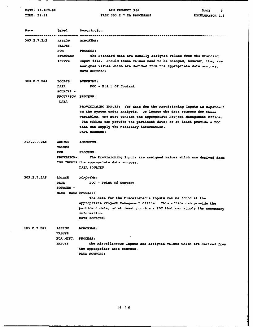
303.2.7.2A3 ASSIGN ACRONYMS:
VALUES
FOR PROCESS:
STANDARD The Standard data are usually assigned values from the standard
INPUTS Input file. Should these values need to be changed, however, they are
assigned values which are derived from the appropriate data sources.
DATA SOURCES:
303.2.7.2A4 LOCATE ACRONYMS:
DATA POC - Point Of Contact
SOURCES -
PROVISION PROCESS:
DATA
PROVISIONING INPUTS; The data for the Provisioning Inputs is dependent
on the system under analysis. To locate the data sources for these
variables, one must contact the appropriate Project Managemnt Office.
The office can provide the pertinent data; or at least provide a POC
that can supply the necessary information.
DATA SOURCES:
303.2.7.2A5 ASSIGN ACRONYMS:
VALUES
FOR PROCESS:
PROVISION- The Provisioning Inputs are assigned values which are derived from
ING INPUTS the appropriate data sources.
DATA SOURCES:
303.2.7.2A6 LOCATE ACRONYMS:
DATA POC - Point Of Contact
SOURCES -
MISC. DATA PROCESS:
The data for the Miscellaneous Inputs can be found at theappropriate Project Management Office. This office can provide the
pertinent data; or at least provide a POC that can supply the necessary
information.
DATA SOURCES:
303.2.7.2A7 ASSIGN ACRONYMS:
VALUES
FOR MISC. PROCESS:
INPUTS The Miscellaneous Inputs are assigned values which are derived from
the appropriate data sources.
DATA SOURCES:
B-18

DATE: 9-AUG-88 APJ PROJECT 966 PAGE I
TIME: 12:11 TASK 303.2.7.2A DATA FLOWS EXCELERATOR 1.8
Name Label Description
AMCP 706-132 MAINTENANCE Maintenance Engineering Techniques are the activities of equipment
ENGINEERING maintenance which develop concepts, criteria, and technical
TECHNIQUES requirements during the conceptual and acquisition phases to be applied
and maintained in a current status during the operational phase to
assure timely and adequate economic maintenance support of weapons and
equipments.
FUNC FUNCTIONAL Identification of the operations and support functions that must be
REQUIREMENTS performed for each system/equipment alternative under consideration and
SELECTED then identification of the tasks that must be performed in order to
ITEM operate and maintain the new system/equipment in its intended
environment.
These functions shall be identified to a level commensurate with
design and operational scenario development, and shall include both
peacetime and wartime functions.
These data will be available from the Concept Formulation Packagewhich will include a Feasibility Study as well as Advance Product
Planning. The Feasibility Study from the Concept Formulation Package
will consist of a Needs Analysis, the System Operational Requiremeents.
and the System Maintenance Concept. Advance Product Planning is
concerned with Plans and specifications of the equipment/system.
HIST HISTORICAL Prior to the actual test and field use of the enri item, it will be
SUPPORT DATA necessary to develop various reliability, maintainability, and
END ITEM availability parameters which are required to support the data base for
LOGISTICAL application to the Palman Model. These quantifications of the
EQUIVALENTS availability parameters may be derived from an analysis of logistically
equivalent systems, operating in similar environmental and operating
conditions. These data will be extracted from the historical files and
used in the development of the model inputs for the end item and for
each of its lower indenture components, modules, or parts.
LOPRA POLICY LORA POLICY In the selection of the parameters for application to the Palman
RELATIVE TO Model, it will be necessary to transfer the policy and guidance of
AMC-R 700-27 AMC-R 700-27 to the analyst and programs assigned to the application of
the Palman Model to the end item and its lower indentures of the Work
Breakdown Structure.
MISC/DATA MISCELLAN- The Miscellaneous Data is used to assign values to the
EOUS Miscellaneous Inputs. The data is supplied by the user, in the form of
VARIABLES input file, to the inputs of the Palman Model.
DATA
B-19
DATE: 9-AUG-88 APJ PROJECT 966 PAGE 2
TIME: 12:11 TASK 303.2.7.2A DATA FLOWS. EXCELERATOR 1.e
Name Label Description
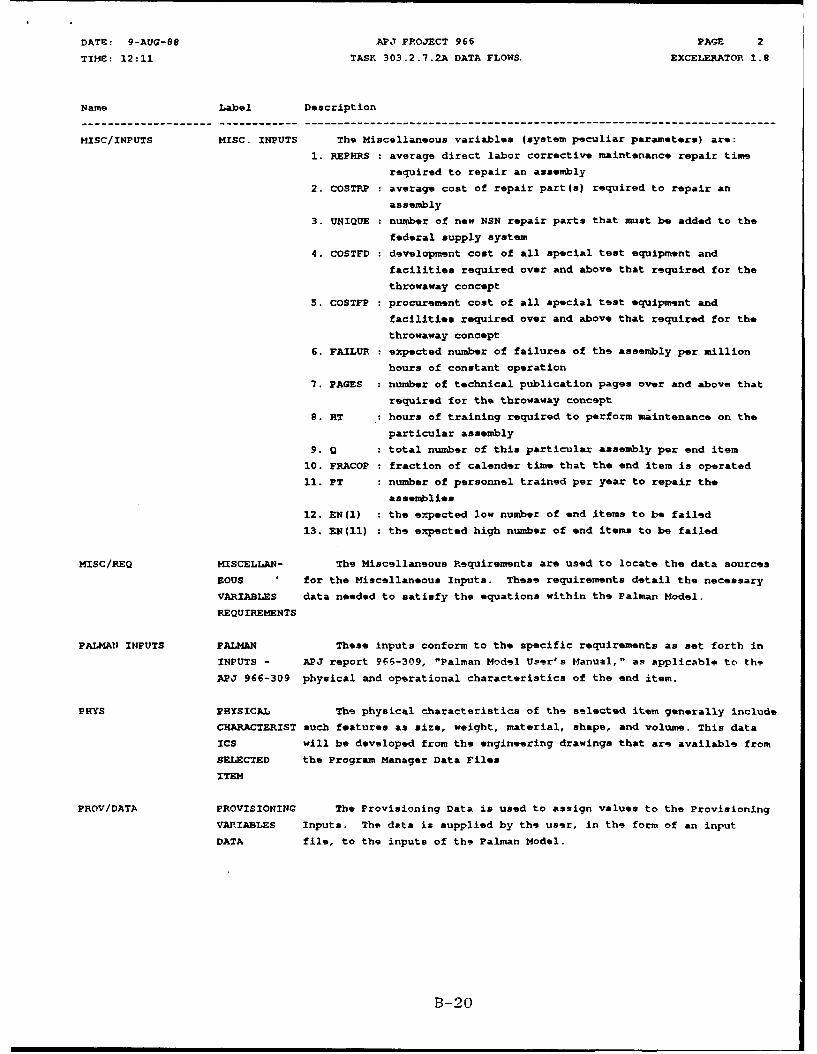
MISC/INPUTS MISC. INPUTS The Miscellaneous variables (system peculiar parameters) are:
1. REPHRS : average direct labor corrective maintenance repair time
required to repair an assembly
2. COSTPP : average cost of repair part(s) required to repair an
assembly
3. UNIQUE : number of new NSN repair parts that must be added to the
federal supply system
4. COSTFD : development cost of all special test equipment and
facilities required over and above that required for thethrowaway concept
5. COSTFP : procurement cost of all special test equipment and
facilities required over and above that required for thethrowaway concept
6. FAILUR expected number of failures of the assembly per million
hours of constant operation
7. PAGES number of technical publication pages over and above that
required for the throwaway concept
8. HT : hours of training required to perform maintenance on the
particular assembly
9. Q total number of this particular assembly per end item
10. FRACOP : fraction of calender time that the end item is operated
11. PT : number of personnel trained per year to repair the
assemblies
12. EN(l) : the expected low number of end items to be failed
13. EN(II) : the expected high number of end items to be failed
MISC/REQ MISCELLAN- The Miscellaneous Requirements are used to locate the data sources
EOUS for the Miscellaneous Inputs. These requirements detail the necessary
VARIABLES data needed to satisfy the equations within the Palman Model.
REQUIREMENTS
PALMAN INPUTS PALMAN These inputs conform to the specific requirements as set forth in
INPUTS - APJ report 966-309, "Palman Model User's Manual," as applicable to the
APJ 966-309 physical and operational characteristics of the end item.
PHYS PHYSICAL The physical characteristics of the selected item generally include
CHARACTERIST such features as size, weight, material, shape, and volume. This data
ICS will be developed from the engineering drawings that are available from
SELECTED the Program Manager Data Files
ITEM
PROV/DATA PROVISIONING The Provisioning Data is used to assign values to the Provisioning
VARIABLES Inputs. The data is supplied by the user, in the form of an input
DATA file, to the inputs of the Palman Model.
B-20

DATE: 9-AUG-88 APJ PROJECT 966 PAGE 3
TIME: 12:11 sASK 303.2.7.2A DATA FLOWS EXCELERATOR 1.9
Name Label Description
PROV/INPUTS PROVISIONING The Provisioning variables (supply related parameters) are:
INPUTS
1. OST(l) : Order and Ship Time between equipment and direct exchange
2. OST(2) : OST in days between DX to Maintenance Level Supply (MLS)
3. OST(3) : OST in days between MLS and Depot
4. OST(4) : OST in days between Depot and Factory
5. OST(5) : OST in days for parts to be obtained by maintenance
facility
6. TAT : Turn Around Time in days for assemblies at maintenance
facility
7. CKK : Safety Stock Coefficient (decimal %), percent of stock
above demand to cover delays
8. RPNSTD :Perecnt of repair parts that are non-standard, requiring
new NSN's
9. INIPA : Minimum number of days of authorized assembly stockage
10. INIPP : Minimum number of days of authorized parts stockago
11. DXN : Number of DX supply locations
12. MXD Number of Maintenance Level Supply locations
13. PNFAIL : Percent of non-operational failures due to obsolescence,
shelf life, etc.
FROV/PfEQ PROVISIONING The Provisioning Requirements are used to locate the data sources
VARIABLES for the Provisioning Inputs. These requirements detail the necessary
REQUIREMENTS data needed to satisfy the equations within the Palman Model.
RLA/RQMNTS REPAIR LEVEL DI-R-3549A (sequence 1) states the requirements of a report which
ANALYSIS are to be addressed in the End Item Level of Repair Analysis. The
REPORT * specific requirments are abstracted and forwarded to the process to
REQUIREMENTS establish the Palman database to insure that these requirements are
met.
SELECT SELECTED This data flow will represent the iteration of the selection
ANALYSIS of items for the Palman Model evaluation. The first selection will be
ITEM the equipment/system as an end item. Following iterations will include
major components, modules, and LRU as set forth in the WDS.
STD/DATA STANDARD The Standard Data is used to assign values to the Standard Inputs.
VARIABLES The data is supplied by the user, in the form of an input file, to the
DATA inputs of the Palman Model.
B-21
DATE: 9-AUG-s8 APJ PROJECT 966 PAGE 4
TIME: 12:11 TASK 303.2.7.2A DATA FLOWS EXCELERATOR 1.e
Name Label Description
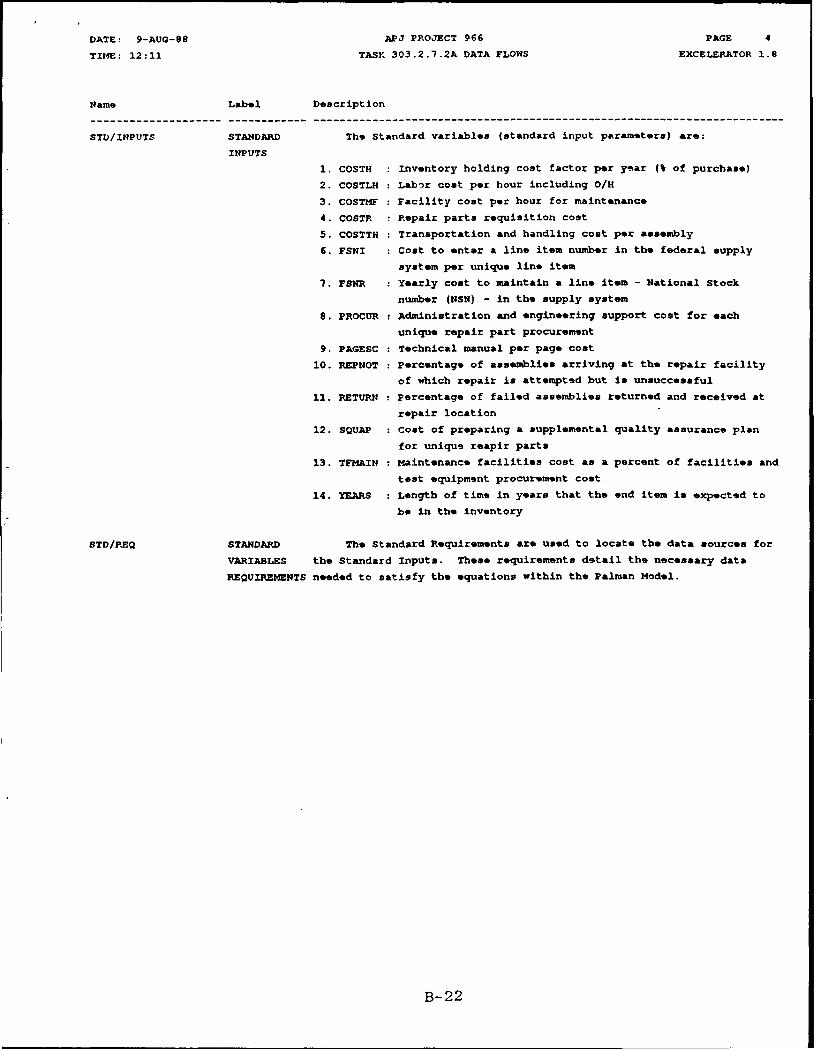
STD/INPUTS STANDARD The Standard variables (standard input parameters) are:
INPUTS
1. COSTH : Inventory holding cost factor per year (% of purchase)
2. COSTLH : Labor cost per hour including O/H
3. COSTMF : Facility cost per hour for maintenance
4. COSTR : Pepair parts requisition cost
5. COSTTH : Transportation and handling cost per assembly
6. FSNI : Cost to enter a line item number in the federal supply
system per unique line item
7. FSNR : Yearly cost to maintain a line item - National Stock
number (NSN) - in the supply system
9. PROCUR Administration and engineering support cost for each
unique repair part procurement
9. PAGESC : Technical manual per page cost
10. REPNOT : Percentage of assemblies arriving at the repair facility
of which repair is attempted but is unsuccessful
11. RETURN : Percentage of failed assemblies returned and received at
repair location
12. SQUAP : Cost of preparing a supplemental quality assurance plan
for unique reapir parts
13. TFMAIN : Maintenance facilities cost as a percent of facilities and
test equipment procurement cost
14. YEARS : Length of time in years that the end item is expected to
be in the inventory
STD/REQ STANDARD The Standard Requirements are used to locate the data sources for
VARIABLES the Standard Inputs. These requirements detail the necessary data
REQUIREMENTS needed to satisfy the equations within the Palman Model.
B-22

VATE: 9-AUG-98 APJ PROJECT 966 PAGE
TItZE: 12:25 TASK 303.2.7.2A DATA STORES EXCELERATOR 1.8
Name Label Description
AMC-R 700-27 LOPA AMC-R 700-27, "Level of Repair Analysis (LORA) Program," prepared
by HQ, U.S. Army Materiel Command (March '85) sets forth the
responsibilities and products required of a Level of Repair Analysis.
Appendix C identifies Palman as applicable to specific aspects of
repair analysis, while OSAMM is considered applicable to system/end
item analysis.
AMCP 706-132 MAINT. ENGR. AMCP 706-132 will provide the maintenance engineering techniques
TECHNIQUES applicable to the development of the variables for application of the
Palman Model, the end item, and its major components, items, and parts.
HIST. FILES HISTORICAL This data store contains data previously acquired on the
FILES system/equipment under investigation or some similar system and may
address the following areas:
1. Reliability Data
2. Failure Rate Data
3. Spares and Spares Funding Data
The availability, accuracy, and relevancy of experience of
historical databases on similar existing systems is crucial for
accomplishment of the task in question, namely Repair Level Analysis.
PM/DF PROGRAM MANAGER CONTAINS THOSE FILES AND DATA WHICH APME NORMALLY DEVELOPED BY AND/OR
DATA FILE RETAINED BY THE PROGRAM MANAGER FOR PROPER MANAGEMENT OF THE DEVELOPMENT
PROGRAM. THESE FILES INCLUDE:
1. ENGINEERING DRAWINGS
2. ENGINEERING CHARACTERISTICS
3. DT/OT RESULTS
4. CONCEPT FORMULATION PACKAGE (CFP)
5. DESIGN CONCEPT PAPER (DCP)
6. TYPE TECHNICAL REVIEWS REQUIRED
7. MILESTONE SCHEDULES
S. FUNDING PROFILES
9. REQUIRED OPERATIONAL CAPABILITIES (ROC)
10. ITEM/EQUIPMENT SPECIFICATIONS
11. ITEM/EQUIPMENT MISSIONS & FUNCTIONS
12. EQUIPMENT, MANPOWER, AND TECHNICAL RISK ASSESSMENTS (FROM
LSA TASK 301.2.3
13. TRADE OFF DETERMINATION ANALYSIS (TOD)
14. TRADE OFF ANALYSIS (TOA)
15.BEST TECHNICAL APPROACH ANALYSIS (BTA)
16. COST AND OPERATIONAL-EFFECTIVENESS ANALYSIS (COEA)
RJLA REPORT REPAIR LEVEL This Data Item Description (DID) contains the details required in
AN.ALYSIS REPORT a report on the optimum Repair Level of Analysis. Although the DID
makes reference to an Air Force application, sequence I of this DID
states the reporting requirement for the end item Level of Repair
Analysis (LORA).
B-23
DATE: 9-AUG-88 APJ PROJECT 966 PAGE I
TIME: 12:18 TASK 303.2.7.2A EXTERNAL ENTITIES EXCELERATOR 1.6
fame Label Description
PALM" MODEL PALMAN The Palman Model has been developed to evaluate the breakoven
MODEL purchase cost for a weapons system component or assembly and to let the
user make a decision to either repair the component/assembly or discard
it.
The operation and specification of the inputs required for the
Palman Model are described in the APJ Report 966-309, "Palman Model
User's Manual."
The Palman Model is written in FORTRAN IV so that is easily
portable to most computer systems with a keyboard, monitor, file
system, and printer.
B-24
0
-1,
B-25
DATE: 9-AUG-88 APJ PROJECT 966 PACE 1
TIME: 12:08 TASK 303.2.7.3A PROCESSES EXCELERATOR 1.8
Name Label Description
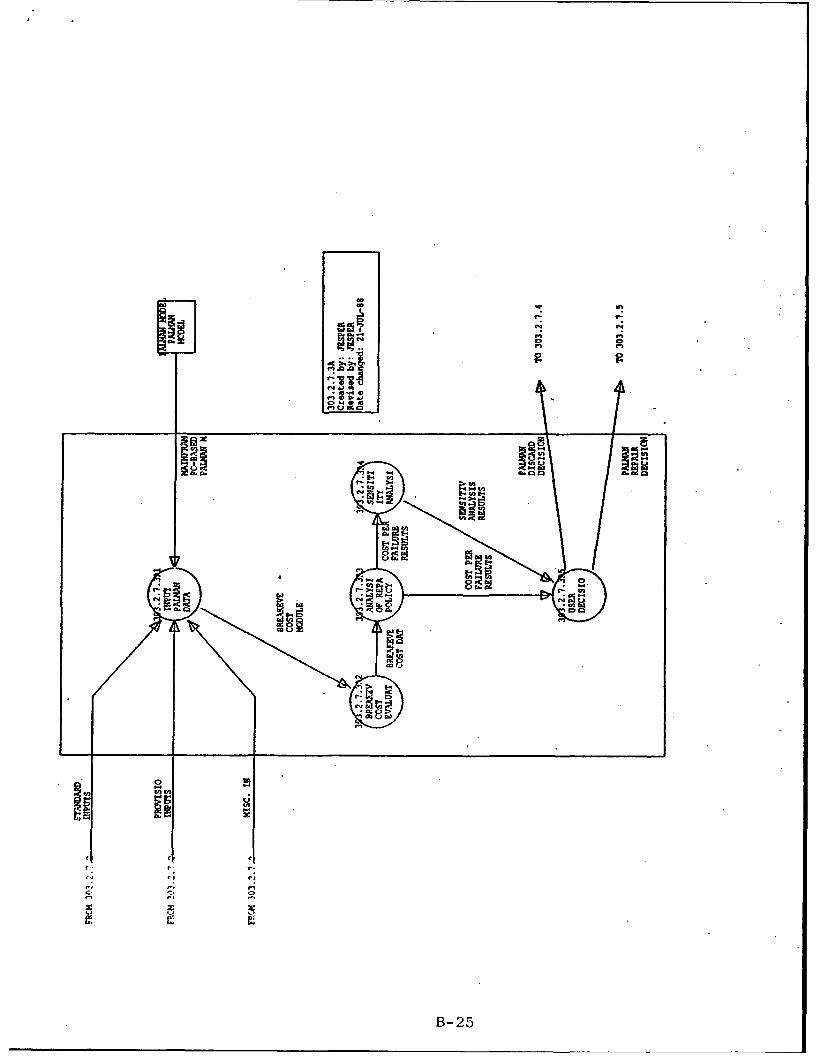
303.2.7.3A1 INPUT ACRONYMS:
PALMAN
DATA PURPOSE:
To provide the algorithms of the Palman Model with the necessary
data to perform the required calculations.
DATA SOURCES:
Standard Input File, Provisioning Input File, Miscellaneous Input
File
303.2.7.3A2 BR1&XEVEN ACRONYMS:
COST
EVALUATION PURPOSE:
This process is the primary feature of the Palman Model. It
calculates the breakeven point where repair cost and throwaway cost are
equal. The user then makes the Repair/Discard decision based on the
results of this process.
DATA SOURCES:
303.2.7.3A3 ANALYSIS ACRONYMS:
OF REPAIR
POLICY - PROCESS:
COST PER This process provides an analysis of repair policy cost per
FAILURE failure. For each cost element, the cost per failure and the
percentage cost contribution is output.
DATA SOURCES:
303.2.7.3A4 SENSITIV- ACRONYMS:
ITY
ANALYSIS PURPOSE:
The Sensitivity Analysis provides the user with information
regarding the variables that most influence the breakeven cost value.
This analysis shows how the breakeven cost value changes as a
particular variable is changed.Two types of sensitivity analyses exist within the Palman Model:
Standard and Unique. If the Standard analysis is selected, the program
automatically chooses the variables to he considered. If the Unique
analysis is selected, the user selects a variable to be considered and
then enters the low value and the high value for the sensitivity range.
DATA SOURCES:
B-26

DATE: 9-AUG-88 APJ PROJECT 966 PAGE 2
TIME: 12:08 TASK 303.2.7.3A PROCESSES EXCELERATOR 1.8
Name Label Description
303.2.7.3A5 USER ACRONYMS:
DECISION
PROCESS:
Based primarily on the results from the Broakeven Cost Evaluation,
along with information provided by the Sensitivity Analysis and the
Analyis of Repair Policy - Cost Per Failure, the user makes the Repair/
Discard decision.
If the replacement cost is less than the breakeven cost, the
decision should be Discard. If the replacement cost is greater than
the breakeven cost, the decision should be Repair. However, If the
replacement cost is close to the breakeven cost, the user should
scrutinize the values of those variables deemed critical by the
sensitivity analysis. Then the model should be re-run, and the
results re-examined.
DATA SOURCES:
B-27
DATE: 9-AUG-88 APJ PROJECT 966 PAGE 1
T!IME: 12:10 TASK1 303.2.7.3A DATA FLOWS EXCELE•PATOR 1.8
Nam's Label Description
BE/COST/DATA BRE -,N The Breakeven Cost Data is the primary source of information
COST DATA used in the Repair/Discard decision. Additionally, data from the
Breakeven cost analysis is used in the subsequent operations made by
the model.
MISC/INPUTS MISC. INPUTS The Miscellaneous variables (system peculiar parameters) are:
1. REPHRS : average direct labor corrective maintenance repair time
required to repair an assembly
2. COSTRP : average cost of repair part (s) required to repair an
assembly
3. UNIQUE : number of new NSN repair parts that must be added to the
federal supply system
4. COSTFD development cost of all special test equipment and
facilities required over and above that required for the
throwaway concept
5. COSTFP : procurement cost of all special test equipment and
facilities required over and above that required for the
throwaway concept
6. FAILUR expected number of failures of the assembly per million
hours of constant operation
7. PAGES number of technical publication pages over and above that
required for the throwaway concept
8. HT : hours of training required to perform maintenance on the
particular assembly
9. Q : total number of this particular assembly per end item
10. FRACOP : fraction of calender time that the end item is operated
11. PT number of personnel trained per year to repair the
assemblies
12. EN(l) : the expected low number of end items to be failed
13. EN(ll) : the expected high number of end items to be failed
PAL/INPUT/DATA PALMAN The Palman Input Data (Standard, Provisioning, and Miscellaneous)
INPUT is used by the model to perform the necessary calculations.
DATA
PAL/LINE MAINFRAME OR An "on line" Palman Model run from either a mainframe or personal
PC-BASED computer is applied to the Repair/Discard analysis.
PALMAN MODEL
ON LINE
PALMAZ./DISC/DEC PALMAN The Palman Model has demonstrated that discarding the failed
DISCARD end item and replacing it with a new equipment/system is the most
DECISION economical decision.
rALHAIi/REP/DEC PALMAN The Palman program has shown that the most economical decision is
REPAIR Repair rather than Discard for selected end items, components, parts, or
DECISION modules. These decisions constitute the major input to the ne:ct
decision concerning the ideal maintenance level for the repair to be
effected. Using the Optimum Supply and Maintenance Model (OsA11M), one
can determine at which echelon each maintenance function should be
performed, or whether the maintenance function should be eliminated
altogether.
B-28
DATE: 9-AUG-88 APJ PROJECT 966 PAGE 2
TIME: 12:10 TASK, 303.2.7.3A DATA FLOWS EXCELEPATOR 1.8
Nom- Label Description--------------------.-.----------.-.----------------------------------------------------------------------
PROV/INPUTS PROVISIONING The Provisioning variables (supply related parameters) are:
INPUTS
1. OST(1) : Order and Ship Time between equipment and direct exchange
2. OST(2) : OST in days between DX to Maintenance Level Supply (MLS)
3. OST(3) : OST in days between MLS and Depot
4. OST(4) : OST in days between Depot and Factory
5. OST(5) : OST in days for parts to be obtained by maintenance
facility
6. TAT Turn Around Time in days for assemblies at maintenance
facility
7. CKK Safety Stock Coefficient (decimal %), percent of stock
above demand to cover delays
S. RPNSTD : Perecnt of repair parts that are non-standard, requiring
new NSN's
9. INIPA : Minimum number of days of authorized assembly stockage
10. INIPP : Minimum number of days of authorized parts stockage
11. DXN : Number of DX supply locations
12. mNw Number of Maintenance Level Supply locations
13. PNFAIL Percent of non-operational failures due to obsolescence,
shelf life, etc.
REPAIR/POLICY/COST COST PER A breakdown of the cost per failure as well as the percent
FAILURE contribution to the total cost per failure for each cost element.
RESULTS
SENS/ANAL/RESULTS SENSITIVITY The results of the Sensitivity Analysis reveal those variables
ANALYSIS which have the greatest influence on the breakeven cost.
RESULTS
B-29
DATE: 9-AUG-99 ArJ PROJECT 966 PAGE 3
TIME: 12:10 TASK 303.2.7.3A DATA FLOWS EXCELERATOR 1.8
Name Label Description
STD/INPUTS STANDARD The Standard variables (standard input parameters) are:
INPUTS
1. COSTH : Inventory holding cost factor per year (% of purchase)
2. COSTLH : Labor cost per hour including O/H
3. COSTMF : Facility cost per hour for maintenance
4. COSTR : Repair parts requisition cost
5. COSTTH : Transportation and handling cost per assembly
6. FSNI Cost to enter a line item number in the federal supply
system per unique line item
7. FSNR : Yearly cost to maintain a line item - National Stock
number (NSN) - in the supply system
8. PROCUR Administration and engineering support cost for each
unique repair part procurement
9. PAGESC : Technical manual per page cost
10. REPNOT Percentage of assemblies arriving at the repair facility
of which repair is attempted but is unsuccessful
11. RETURN Percentage of failed assemblies returned and received at
repair location
12. SQUAP Cost of preparing a supplemental quality assurance plan
for unique reapir parts
13. TFMAIN : Maintenance facilities cost as a percent of facilities and
test equipment procurement cost
14. YEARS : Length of time in years that the end item is e.-4pscted to
be in the inventory
B-30

DATE: 9-AUG-88 APJ PROJECT 966 PAGE
TIME: 12:20 TASK 303.2.7.3A EXTERNAL ENTITIES EXCELERATOR 1.8
Name Label Description
PALMAN MODEL PALMAN The Palman Model has been developed to evaluate the breakeven
MODEL purchase cost for a weapons system component or assembly and to let the
user make a decision to either repair the component/assembly or discard
it.
The operation and specification of the inputs required for the
Palman Model are described in the APJ Report 966-309, "Palman Model
User's Manual."
The Palman Model is written in FORTRAW IV so that is easily
portable to most computer systems with a keyboard, monitor, file
system, and printer.
B-31
C).
-r-
e~ e
B-3
CM3
B- 32
DATE: 9-AUG-88 APJ PROJECT 966 PAGE 1
TIME: 12:09 TASK 303.2.7.5A PROCESSES EXCELERATOR 1.8
Name Label Description
-------------- ---------- ------------------------------------------------------------------------
303.2.7.5AI PREPARE ACRONYMS:
OSAMM OSAMM - Optimum Supply And Maintenance Model.
DATABASE
PROCESS:
The preparation of the OSAMM database involves gathering
information on the following:
1. End item data
Equipment breakdown structure into indenture levels of components,
modules, and piece parts.
2. Deployment information
The identification of the quantity of equipment, personnel,
facilities, etc. and the expected geographical location to include
transportation and mobility requirements.
3. Maintenance policies to be considered
The established requirements for the overall support of the system
throughout its life cycle.
4. Echelon parameters5. Cost parameters
Cost factors can include personnel labor, transportation,
training, facilities, inventory, data, and consumables.
6. Test equipment data
Includes all tools, condition monitoring equipment, diagnostic and
checkout equipment, metrology and calibration equipment, maintenance
stands, and handling equipment required to support scheduled and
unscheduled maintenance actions associated with the system or product.
7. Repairmen data
Either common or special repairmen may be needed for
equipment/system repair.
8. Component data
9. pseudo-component data
10. Module data
11. Pseudo-module data
12. Application data
This information lists a module, the component to which it
belongs, and the Mean Time Between Failure.
DATA SOURCES:
AMC-P 700-4 Logistic Support Analysis Techniques Guide
B-33
DATE: 9-AUG-88 APJ PROJECT 966 PAGE 2
TIME: 12:09 TASK 303.2.7.5A PROCESSES EXCELEPATOR 1.e
Name Label Description---------------.-.--------.-.----------------------------------------------------------------------
303.2.7.5A2 PREPARE ACRONYMS:
OSAM• OSAMt - Optimum Supply And Maintenance Modg-
INPUT CECOM - Communications Electronics Command
DATA TR - Technical Report
FORMATS
PROCESS:
The equipment/system physical characteristics and operational
data developed in subtask 303.2.7.1 for application to the OSAtM
must be stored on a file consisting of 80 column records. All records
are mandatory except where noted. Some of the variables have default
values which will be used if a zero is input or if the data field for
that variable is left blank. These values should be used only when
better data is not available. The correct values for these variables
may change, but the defaults may not reflect the change for some time.
All data entries should be right justified in their fields except
for alphanumeric variables which should be left justified. The decimal
point will automatically be placed so that the entry has the number of
decimal places indicated. The user may insert his own decimal point
which will override the assumed decimal point, however.
DATA SOURCES:
CECOM-TR-87-3, "Optimum Supply and Maintenance Model," Release
2.0, User's Guide, Sept. '87
303.2.7.5A3 APPLICA- ACRONYMS:
TION TO OSAHM - Optimum Supply And Maintenance Model
OSAMM
PRE- PROCESS:
PROCESSOR , The input data file is read by the OSAMI preprocessor program.
The preprocessor reformats user inputs and computes data required by
the main program. It also performs several edit checks and produces a
variety of error messages. By reviewing the preprocessor output the
user can detect errors in his or her inputs and correct them before
expending the resources to run the full model only to find that there
is an error in the input data.
DATA SOURCES:
303.2.7.5A4 VALIDATE ACRONYMS:
PRE- OSAMM - Optimum Supply And Maintenance Model
PROCESSOR
INPUTS/ PROCESS:
OUTPUTS The OSAMM user must now inspect the output from the preprocessor.
If any errors or discrepancies exist, the user must reconcile them
before the basic OSAMM is applied.
DATA SOURCES:
B- 34
DATE: 9-AUG-88 APJ PROJECT 966 PAGE 3
TIME: 12:09 TASK 303.2.7.5A PROCESSES EXCELEP.TOR 1.8
Name Label Description
303.2.7.5A5 APPLICA- ACRONYMS:
TION TO OSAMM - Optimum Supply And Maintenance Model
OSAMM
MODEL PROCESS:
The OSAMM can be run in either an Optimization Mode or an
Evaluation Mode. In the full Optimization Mode a maintenance concept
which minimizes cost is chosen by the model and evaluated. In the
Evaluation Mode, the costs associated with a maintenance concept chosen
by the user are computed. The Evaluation Mode is useful for performingsensitivity analysis and answering "what if" type questions. Except for
a message which describes the performance of the optimization, the
model's output is the same in either case.
DATA SOURCES:
B-35
DATE: 9-AUG-88 APJ PROJECT 966 PAGE 1
TIME: 12:09 TASK 303.2.7.5A DATA FLOWS EXCELERATOR 1.8
Hant Label Description
OSAM DATA OSAMM The data output by the OSAMM model to the LSAR includes:
DATA
1. Maintenance policies by application
2. Maintenance Task Distributions (MTD's)
3. Replacement Task Distributions (RTD's)
4. Quantity required of each test equipment/repairman at each echelon
5. Number of spares of each component/module allowed at each echelon,
initial spares cost, and consumption spares over the life of the
system
6. Total cost of each component/module for holding, transportation,
requisition, cataloging, bin, and repair
7. Total logistics cost and achieved operational availability
OSAMH DATA BASE OSAMM Data inputs required for application of OSAMO to the
DATA system/equipment at each and every indenture level in its Work
BASE Breakdown Structure. The data have been set forth in S0-column format
as described in the CECOM publication, OSAMM Release 2.0 User's Guide.
(CECOM-TR-87-3)
OSAM4 INPUT DATA OSAMM INPUT PURPOSE OF DATA:
DATA The OSAMM input data is used to prepare the input data formats and
then it is passed on to the Preprocessor.
DATA SOURCE:
B- 36
DATE: 9-AUG-88 APJ PROJECT 966 PAGE 2
TIME: 12:09 TASK 303.2.7.5A DATA FLOWS EXCELERATOR 1.8
flame Label Description
OSAMM INPUT FORMS OSAMM INPUT The specific OSAMM input data formats are as follows:
FORMATS 1. Control Parameters
Run Mode Selector-Defines type of run; indicates type of input data.
Policy Selector Variables-Limits the number of levels that are
considered for certain types of repair or screening actions.
2. End Item Information
MTBF (Mean Time Between Failure) Multiplier-All MTBF's input will
be multiplied by this factor. The false removal rate default input on
this record represents an overall average for the end item.
3. Turnaround Time (TAT) and End Item Repair Information
This record contains default values for TAT's and the screening
detection fraction which are used when specific data is not input with
an individual component or module.
4. End Item Repair Alternatives
These records define End Item Repair Alternatives and contain
lists of test equipments and/or repairmen that are required to repair
the End Item each time it fails.
5. End Item Repair Equip./Repairmen Associated with Specific Equip.
These records contain lists of test equipments and/or repairmen
that are needed to repair the end item when specific components fail.
6. Deployment Information
This record contains SESAME (Selected Essential-Item Stockage
Availability Method) model data concerning the supply structure which
supports the end item.
7. Labor Rates and Transportation Information
This record defines common repairmen at each maintenance level
and data which is used to calculate transportation costs.
8. Cost Parameters
The record is required even if all of its fields are blank.
9. Test Equipment Information
The first record contains basic information and identification
number. Parameters that may vary by maintenance level are listed on
the second record.
10. Repairman Information
The first record contains basic information, and the second
contains parameters that may vary by echelon.
11. Component Information
The first record is a 4 character, alphanumeric identification.
The second record defines the first repair alternative for the
component and contains the identification numbers of test equipments
and/or special repairmen needed for every repair action.
12. Pseudo-Compcnent Information
This information follow recular components in the file. Only
one record is required unless the pseudo-component is a candidate
for screening. Since pseudo-components are non-repairable, no repair
alternatives are needed.
13. Module Information
Records arranged in the same manner as component information.
14. Pseudo-Module Information
Records arranged in the same manner as pseudo-component
information except no failure rate information is input. As with
repairable ncodules, failure information in entered on the application
records.
15. Applicatinn Information
B-37
DATE: 9-AUG-88 AFJ PROJECT 966 PAGE 3
TIME: 12:09 TASK 303.2.7.5A DATA FLOWS EXCELERATOR 1.8
Name Label Description--------------------.-.----------.-.----------------------------------------------------------------------
belongs, and the MTBF of the module in this application. Multiple
occurrences of a module in the same component should be entered as one
application. Since each repairable component must contain at least one
module, it must be listed with at least one application.
OSAHM INPUTS OSAMM A specification of the inputs required of the system/item being
INPUT evaluated from the view point of Level of Repair. These inputs must
REQUIREMENTS conform to the requirements of OSAMM as spelled out in the OSAMM User's
Manual.
OSAMM/DISC/DEC OSAMM The OSAMO decision regarding the Level Of Repair Analysis is no
DISCARD repair at all. The failed equipmont/system is discarded.
DECISION
OSAMM/REP/DEC OSAMM Repair level decisions made by the model are output by
REPAIR application. The model will describe what should be done when the end
DECISION item fails due to the failure of a certain module in a certain
component. The model will also determine which components and modules
should be discarded instead of repaired. This set of repair level
decisions is commonly referred to as the "maintenance concept" for the
equipment.
PALMAN/REP/DEC PALMAN The Palman program has shown that the most economical decision is
REPAIR Repair rather than Discard for selected end items, components, parts, or
DECISION modules. These decisions constitute the major input to the next
decision concerning the ideal maintenance level for the repair to be
effected. Using the Optimum Supply and Maintenance Model (OSAMM), one
can determine at which echelon each maintenance function should be
performed, or whether the maintenance function should be eliminated
altogether.
PROC/OUTPUTS PRE- The Preprocessor outputs are used by the main program for
PROCESSOR computation as well as edit checks and error messages.
OUTPUTS
VAL/PREPROC/OUTPUTS VALIDATED The validated Preprocessor output data is used by the OSAMM main
PREPROCESSOR program to make the supply and maintenance decisions and produce the
DATA necessary LSAR data.
B-38

DATE: 9-AUG-88 APJ PROJECT 966 PAGE
TIME: 12:26 TASK 303.2.7.5A DATA STORES EXCELERATOR 1.9
Name Label Description---------------.-.-------------.-.----------------------------------------------------------------------
DATA FILE - OSA DATA FILE-OSAMN A temporary storage of the 80 column cards containing the OSA•O4
APPLICATION inputs required of the equipment/system. This file may be retained for
historical purposes (a baseline for updates) or destroyed at completion
of its use.
LSAR FILE LSAR FILE This file or records holding area contains:
1. The equipment/system LSA Task reports or their equivalent.
2. The equipment/system LSAR master records sheet information.
3. The equipment/system LSAR reports when system is automated.
It contains logistics data which can be used to assess the ILS
elements set forth in MIL-STD 1388-1A and conforms to the records/files
prescribed in MIL-STD 1388-2A.
B- 39

DATE: 9-AUG-88 APJ rROJECT 966 PAGE I
TIME: 12:20 TASK, 303.2.7.5A EXTERNdAL ENTITIES EXCELERATOP. 1.8
iam� ILabel Description
OSANM MODEL OSAMM CECOM-TR-87-3, "Optimum Supply and Maintenance Model Release 2.0
MODEL User's Guide," is used to identify the specific inputs required for the
REQUIRE- equipment/system to run the repair level decision model.
MENTS
B-40
ANNEX C
STRUCTURED SYSTEMS ANALYSIS
FUNDAMENTALS
ANNEX C
STRUCTURED SYSTEMS ANALYSIS
Fundamentals
Structured Systems Analysis (SSA) has recently become anindustry standard for generating Data Flow Diagrams (replacing"logic diagrams" or "flow charts") to aid in coordinating thefunctions to be performed by a computer program and itsassociated Inputs/Outputs (I/O). During the SSA, each set of"flow charts" can be checked by the potential user to assurethat there is complete agreement on what is to be done by theprogram, and how it is to be accomplished. It also providesconsiderable flexibility for updating or changing the program.
Six basic elements are used in SSA:
1. Process (PRC)2. Data Flow (DAF)3. Data Store (DAS)4. External Entity (EXT)5. Data Flow Diagram (DFD)6. Data Dictionary (DCT)
PROCESS (Represented by a Circle):
A function or operation to be performed which can beexplained by a set of instructions representing a single task,e.g., "calculate interest on a loan", "prepare a draftreport". If 'the Process description is too complex todescribe in a few steps, it may be necessary to develop alower level description (see below).
DATA FLOW (Lines interconnecting Processes or I/Os):
Each function or Process cannot be a stand-alone in acomplex network. To have any meaning in a program, eachprocess must be initiated by a previous action and/or providedinformation on which to act. Furthermore, a Process mustresult in an output which is the input to the next logicalProcess. These inputs, outputs, or initiating actions areidentified as Data Flows, and are represented by the Data Flowlines indicating its point of origin and the process to whichit provides data.
C-i

DATA STORE (Represented by two parallel lines):
Although some Processes generate data used as input to asucceeding Process, there is often a need to "gather orcollect" information from files in which it is stored. Thisinformation may come from an external source (such as a MIL-STD, Army regulation, historical experience files, etc.), oran internal source or file in which data is temporarily storedfor use by succeeding processes. These Data Stores can bevisualized as a "file cabinet", in which the data are storedfor later retrieval).
EXTERNAL ENTITY (Represented by a Rectangle):
Each program or logical process must have an initiatingaction, a "point" of disposition of the results, and possiblyinput guidance or instructions. Each of these haveauthorities, functions, or applications which are independentof the program Process (although required by the programProcess). Thus, these activities, agencies, or facilities areconsidered "External Entities" to the program.
DATA FLOW DIAGRAM:
The general arrangement of the above can be readily seen.First, the circle or Process describes what has to be done;the interconnecting lines represent the Data Flows, togetherwith the specific description of all I/Os. The Data Storesidentify the source and/or file designation of a data base,and the External Entities represent those activities remotefrom the Process, which are the source of guidance or therecipients of the program. This combination of Processes,Data Flows, Data Stores, and External Entities constitutes a"Data Flow Diagram". The unique feature of the Data FlowDiagram (DFD) is that each process can be consideredindependently, permitting a change to be made in one Processwithout a major change in the overall program.
DATA DICTIONARY:
The Data Dictionary consists of a complete description ofeach of the basic elements. For the Process, it contains astep-by-step description of what has to be performed. Thedescription of the Data Flow identifies the nomenclature ofthe data, a detailed description of its content, and itssource. The Data Stores and External Entities are described,including possible location.
The Data Dictionary (a living document) begins with adescription of the first Process and is continually built-upas the Data Flow Diagrams are expanded, detailed, andeventually completed.
C-2
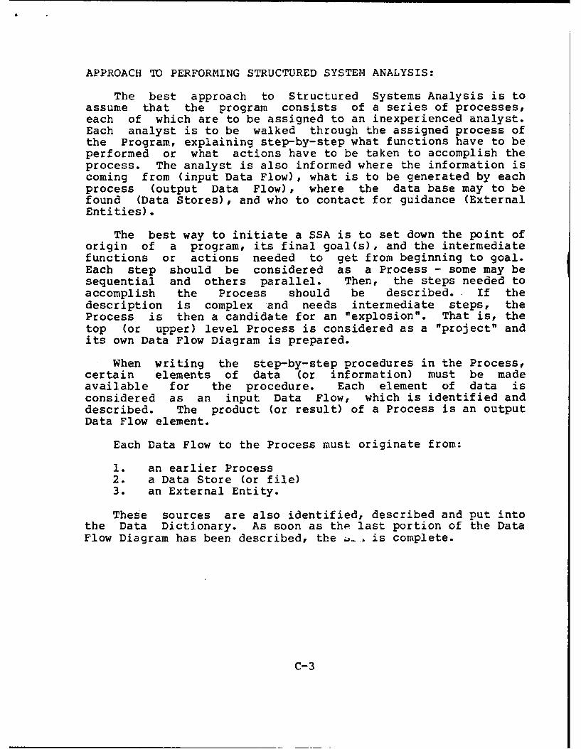
APPROACH TO PERFORMING STRUCTURED SYSTEM ANALYSIS:
The best approach to Structured Systems Analysis is toassume that the program consists of a series of processes,each of which are to be assigned to an inexperienced analyst.Each analyst is to be walked through the assigned process ofthe Program, explaining step-by-step what functions have to beperformed or what actions have to be taken to accomplish theprocess. The analyst is also informed where the information iscoming from (input Data Flow), what is to be generated by eachprocess (output Data Flow), where the data base may to befound (Data Stores), and who to contact for guidance (ExternalEntities).
The best way to initiate a SSA is to set down the point oforigin of a program, its final goal(s), and the intermediatefunctions or actions needed to get from beginning to goal.Each step should be considered as a Process - some may besequential and others parallel. Then, the steps needed toaccomplish the Process should be described.- If thedescription is complex and needs intermediate steps, theProcess is then a candidate for an "explosion". That is, thetop (or upper) level Process is considered as a "project" andits own Data Flow Diagram is prepared.
When writing the step-by-step procedures in the Process,certain elements of data (or information) must be madeavailable for the procedure. Each element of data isconsidered as an input Data Flow, which is identified anddescribed. The product (or result) of a Process is an outputData Flow element.
Each Data Flow to the Process must originate from:
1. an earlier Process2. a Data Store (or file)3. an External Entity.
These sources are also identified, described and put intothe Data Dictionary. As soon as the last portion of the DataFlow Diagram has been described, the • is complete.
C-3

GLOSSARY

GLOSSARY
AMCCOM Armament Munitions and Chemical CommandAMSDL Acquisition Management Systems and
Data Requirements Control ListAPJ American Power Jet CompanyAR Army Regulation
DAF Data FlowDAS Data StoreDCT Data DictionaryDFD Data Flow DiagramDID Data Item Description
EXT External Entity
ILS Integrated Logistic SupportIPM Interactive Palman Model
LORA Level Of Repair AnalysisLSA Logistic Support AnalysisLSAR Logistic Support Analysis Report
MIL-STD Military Standard
OSAMM Optimum Supply And Maintenance Model
PAM PamphletPRC Process
RLA Repair Level Analysis
SSA Structured System AnalysisSSAD Structured Systems Analysis and Design
G-1