ad-a~51 599 - defense technical information center ad-a~51 599 defense nuclear agency alexandria, va...
TRANSCRIPT

AD-A~ 51 599
Defense Nuclear AgencyAlexandria, VA 22310-3398
DNA-TR-90-170
Metal-Metal Microfilamentary Composites for HighStrength Electrical Conductor Applications - Phase 11
James D. Klein, et al.EIC Laboratories, Inc.111 Downey StreetNorwood, MA 02062 ELECTE i
JUN 17 1992
August 1991 A
Technical Report
CONTRACT No. DNA 001-87-C-0150
I A o for Ip : rae";
92 6 0 ~92-15478 N UIII
Destroy this report when it is no longer needed. Do notreturn to sender.
PLEASE NOTIFY THE DEFENSE Y4UCLEAR AGENCY,ATTN: CSTI. 6801 TELEGRAPH ROAD, ALEXANDRIA, VA22310-3398, IF YOUR ADDRESS kINCORRECT. IF YOUWISH IT DELETED FROM THE D)$TRIBUTION UST, ORIF THE ADDRESSEE IS NO LONGER EMPLOYED BY YOURORGANIZATION.

DISTRIBUTION LIST UPDATE
This mailer is provided to enable DNA to maintain current distribution lists for reports. We wouldI appreciate your providing the requested information.
I Add the individual listed to your distribution list.PeaeetrNOEIfaertr the mailing label from
0 Deetethe ite oraniztio/indvidal.the document so that any additions,0 Deetethe ite oraniztio/indvidalchanges, corrections or deletions
I can be made more easily.1 0 Change of address. _______________
INAME:
IORGANIZATION:
IOLD ADDRESS CURRENT ADDRESS
ITELEPHONE NUMBER: )
a
ZI
DNA OR OTHER GOVERNMENT CONTRACT NUMBER: _______________
ICERTIFICATION OF NEED*TO-KNOW BY GOVERNMENT SPONSOR (if other than DNA):
ag SPONSORING ORGANIZATION:_____________________
I CONTRACTING OFFICER OR REPRESENTATIVE: _________________
I SIGNATURE: _ _ _ _ _ _ _ _ _ _ _ _ _ _ _ _ _ _ _ _ _ _ _ _ _ _ _ _ _

DirectorDefense Nuclear AgencyATTN: TITLWashington, DC 20365-1000
DirectorDefense Nuclear AgencyATTN: TITLWashington, DC 20305-1000

REPORT DOCUMENTATION PAGE FmAfvOw4 NO. 0701m
pubme 00llm 1 g 0~ IN Wil a menm d 10mIII 1 nourw 0, 1e g to te ki ronown wauoni de Sources.ceatel on f bft mMn.' eI sugind fo ed ucn Oft hmuml do . to W0 0 Hed mmies3 i ieird widwelon 00erftn afta Pimtw~ . 121 Julavon
1. kmmm bq AGENCYm USE 014LY (LW b4*. REPO Ttm TElm 3k. m 0ROR TYP mAD DAEOVERE D Fwm 2$J~
i 910801 Technical 870908 - 9003314. TITLE AND SUBTITLE 5. FUNDING NUMBERS
Metal-Metal Microflamentary Composites for High Strength C - DNA 001-87-C-0150Electrical Conductor Applications - Phase II PE - 63221C
PR - SF6. AUTHOR(S) TA - SB
James D. Klein. Stuart F. Cogan, Allen Yen and Louis L. Wu WV - DH035 100
7. PERFORMING ORGANIZATION NAME(S) AND ADDRESS(ES) 8. PERFORMING ORGANIZATIONREPORT NUMBER
EIC Laboratories, Inc.111 Downey Street C915FNorwood, MA 02062
9. SPONSORING/MONITORING AGENCY NAME(S) AND ADDRESS(ES) 10. SPONSORING/MONITORINGAGENCY REPORT NUMBER
Defense Nuclear Agency6801 Telegraph Road DNA-TR-90-170Alexandria, VA 22310-3398RAEV/Rodriguez
11. SUPPLEMENTARY NOTES
This work was sponsored by the Defense Nuclear Agency under RDT&E RMC CodeB7661D SF SB 00034 RAEV 3230A 25904D.
12. D STRIBUTIOI1AVAILABIITY STATEMENT 12b. DISTRIULTION CODE
Approved for public release; distribution is unlimited.
13. ABSTRACT (MaW&nWm 00 m)
Continuous-filament Cu-Nb and Cu-Ag composites were fabricated as candidate highstrength electrical conductors. Microflamentary Cu-Nb composites achieved remarkablestrength levels while maintaining good electrical conductivity. By examining the super-conducting properties of the Cu-Nb composites, it was determined that some recoveryprocesses were active In the Nb fibers at relatively low annealing temperatures. However.the flne-flament Cu-Nb wires exhibited excellent pulsed current capabilities. A noveltesting regime called pulsed current fatigue demonstrated the impact of composite designand pulse conditions on pulsed current lifetime. Cu-Ag composites were fabricated toprovide a higher conductivity alternative to Cu-Nb. Although the Cu-Ag results werepromising, a second-generation composite is needed to extend the benefits to the higheststrength levels.
14. SUBJECT TERMS I& NUMER OF PAGIES
Metal-Matrix Composites Microfilamentary Composites 70Hig Strength Wires Pulsed Current Fatigue 1& PRIC COos
17.ECuRrrYCLASSFICATION I5SECRTYCLASSIFITAToN 19. SECURITY CLASSIFICATION 20. LMATION OF AISTRACT
OF REPORT OF THIS PAGE OF ABSTRACT
UNCLASSIFIED UNCLASSIFIED UNCLASSIFIED SARt It0-ago100 SIM r011 (I 1.2-
AmIbMMtI" MNMN fA M e.=81

UNCLASSIFIEDSECURM7 cLASSICAM~N OF Th.S PAGECLASSIFIED BY:
N/A since UnclassifiedDECLASSIFY ON:
N/A since Unclassified
UNCLASSIFID

SUNMARY
The mechanical and electrical properties of continuous-filament Cu-Nb andCu-Ag composites have been surveyed. The mlcroflamentary Cu-Nb compositeswere found to have excellent mechanical strength, good electrical conductivity,and substantial resistance to annealing. As such. the fine-filament Cu-Nbcomposites are excellent materials for high strength electrical conductors. Bydetermining the superconducting properties of the Nb filaments, the annealingbehavior of finely divided Nb was determined. To assess the suitability of theCu-Nb composites for pulsed current applications, a novel testing method calledpulsed current fatigue was Implemented. The technique is unique In that itprovides a cyclic thermo-mechanical loading with an extremely simple exper-imental apparatus.
Cu-Ag composites were fabricated to provide a higher conductivity alternativeto the Cu-Nb system. The anticipated electrical conductivity advantage affordedby Ag filaments is confirmed. Indeed. extrapolation of their conductivity vs.strength behavior indicates that the advantage of Cu-Ag over Cu-Nb will increaseat the higher strength levels. However, Ag is not as aggressive as Nb with regardto developing strength by cold work. Although the present data suggests thathigher strength levels can be accessed, the strengths of the Cu-Ag wires fabricateddo not approach those of the best Cu-Nb samples.
Accesion For
NTIS CRA&IDTIC TAB L!Urnainnou rced J
y ...... ..... ...............O Dist ib, tic'; I
Dist b o
U1
... .. .. ... ....

TABLE OF CONTENTS
Section Page
SUB4AR ................................................ IiiLIST OF ILLUSTRATIONS ............................................... v
V, ' OF TABL S ........................... .................................
1 INTRODUCTION ................................................................ 1
2 SPECIFIC Cu-Nb COMPOSIES .................... 2
3 STrENGTH AND RESISTvr1Y OF Cu-Nb COMPOSrM .... 5
3.1 Concept and Approach ............................................... 53.2 Introduction ............................................................... 53.3 Results and Discussion .............................................. 63.4 Conclusions .............................................................. 10
4 ANEAL G BEHAVIOR OF Nb FAMENTS ...................... I I
4.1 Concept and a ................................. I I4.2 IntroducUou ..... ................ ......4.3 E erm t.............. . .. ......................................... 12
4.4 Results and D0acu... ................................ 134o5 C n us ..... o..................................... .............. 20
5 PULSED CURRENT FATIGUE OF Cu-Nb COMPOSITES .... 23
5.1 Concept and Approac .............................................. 235.2 Introduction ...... ... ....... 0........cu ........................ 235.3 .0-00~n .................. .. .................................... 24
5.4 Results and Discussion .......................................... 285.5 C...cluslci ....... *.................... . ...... 33
6 Cu-Ag COMPOSr S ................. ................ . ........ 35
6.1 Concept and Approach ............................................... 356.2 SpecificCu-Ag t ....................................... 356.s Rmuts and u .o .......................................... 376.4 Canc ............................................................ 40
7 RECOM0ENDAIONS .................................................... 42
8 REFE REN E ....... ....................... ...... ..... o....................... 43
APPENDICESA P SONNEL,. ....................................................... o........... 45B pUBuCATMON ............. ....... ................................. . .......... 53
iv
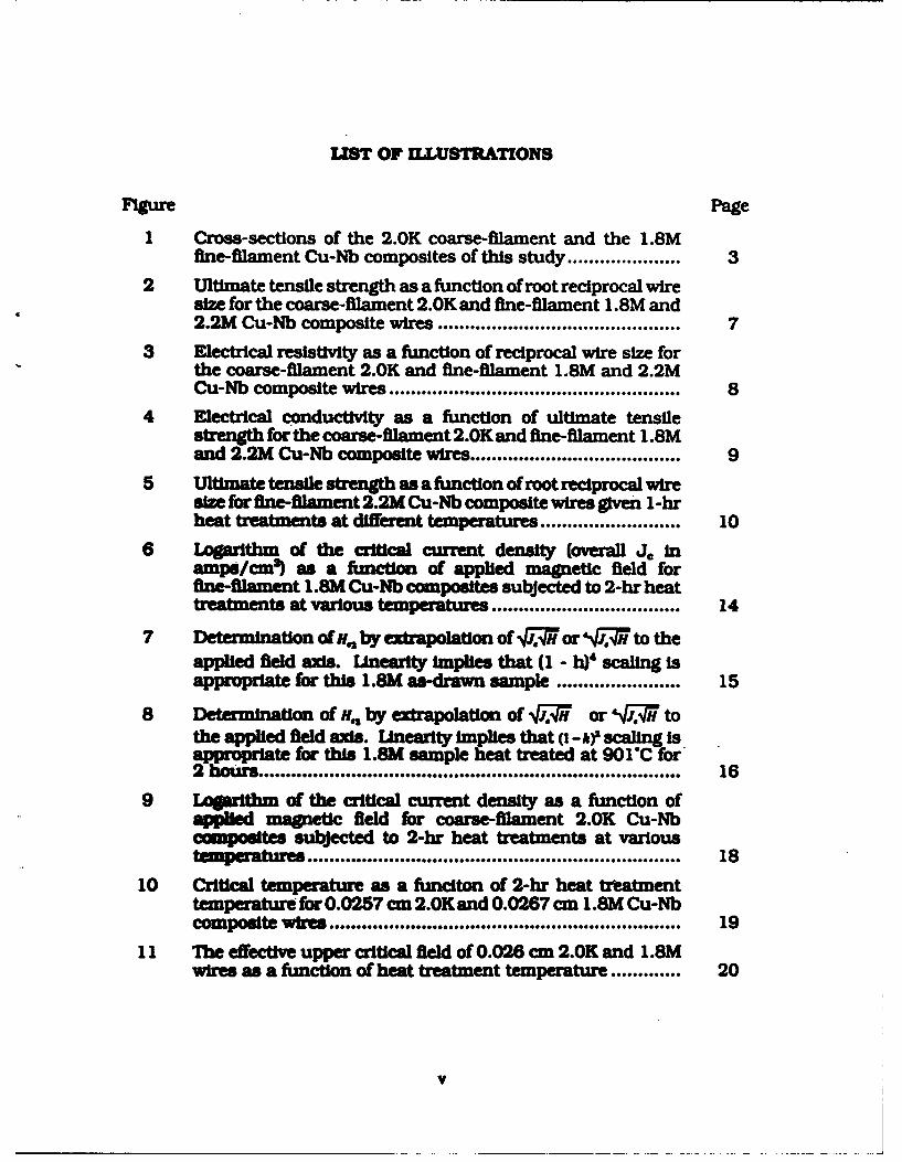
LIST OF ILLUSTRATIONS
Figure Page
1 Cross-sections of the 2.0K coarse-filament and the 1.8Mfine-filament Cu-Nb composites of this study ..................... 3
2 Ultimate tensile strength as a function of root reciprocal wiresize for the coarse-filament 2.0K and fine-filament 1.8M and2.2M Cu-Nb composite wires ............................................. 7
3 Electrical resistivity as a function of reciprocal wire size forthe coarse-filament 2.0K and fine-filament 1.8M and 2.2MCu-Nb composite wires ...................................................... 8
4 Electrical conductivity as a function of ultimate tensilestrength for the coarse-filament 2.0K and fine-filament 1.8Mand 2.2M Cu-Nb composite wires ....................................... 9
5 Ultimate tensile strength as a function of root reciprocal wiresize for fine-flament 2.2M Cu-Nb composite wires given 1-hrheat treatments at different temperatures .......................... 10
6 Logarithm of the critcal current density (overall J. Inamps/cm') as a function of applied magnetic field forfine-ftiment 1.SM Cu-Nb composites subjected to 2-hr heattreatments at various temperatures ................................... 14
7 Determination of m,, by extrpolation of qJ.1 or VrP7H to theapplied field axis. Unearity implies that (1 -li scaling isappropriate for this 1.8M as-drawn sample ....................... 15
8 Determination of H., by extapolation of q or 'J4r tothe applied field axis. Linearlty Implies that (i-h)' scaling is
r Pte for this I.SM sample heat treated at 901"C for2 h rs................................ ........ *..................................... 16
9 Lpogadth of the critical current density as a function ofa1 magnetic field for coarse-filament 2.0K Cu-Nbcamposites subjected to 2-hr heat treatments at varioustem p atne ..................................................................... 18
10 Critical temperature as a funciton of 2-hr heat treatmenttemperature for 0.0257 cm 2.0K and 0.0267 cm 1 .8M Cu-Nbcomposite wires ............................................................... 19
11 The effective upper critical field of 0.026 cm 2.0K and 1.8Mwires as a function of heat treatment temperature ............. 20
V

UST OF ILLUSTRATIONS (Continued)
Frguc Page
12 Cross-sections of representative colonies of the 1.8M doubleextrusion composite are shown in the as-drawn conditonand after a 2-hour heat treatment at 700*C ....................... 22
13 A schematic diagram of the experimental setup for pulsedcurrent fatigue testing ....................................................... 25
14 The calculated thermal and stress history of a wire subjectedto pulsed current fatigue................................................... 26
15 The mechanically severe 30 amp. 20 msec, 0.75 Hz pulseconditions applied to a 0.018 cm 1.8M wire cause steady-state oscillations of the wire length corresponding to largetemperature and stress fluctuations as a function of time.. 27
16 Pulsed current fatigue results of 0.0257 cm 2.0K wiresresulting from 10 mec, 10 Hz pulsing at 15 and 20 amps 29
17 Pulsed current fatigue results of 0.0267 cm 1.SM wiresresulting from 10 isc. 10 Hzt pulsing at 15. 20. and 25am ps ........... ................. ...... .......... .......................... ..... 30
18 Pulsed current faigue results of 0.018 cm 1.8M wiresresulting from three pulse current fatigue conditions havingthe sane average power Input.................................... 32
19 Fracture surfaces of 0.018 cm 1.8M wires subjected to 10amp. 10 msec, 13.5 Hz, 138OMPa and 30 amp. 20 msec.0.75 Hz. 345 &Pa pulsed current fatigue ............................... 34
20 Cross-sections of the 1.2K coarse-filament and the 1.3M finelament Cu-Ag amposites of this study ... .......................... 36
21 Ultimate tensile strength as a function of root reciprocal wiresne for the fine Mament 1.3M Cu-Ag. 1.8M Cu-Nb. and 2.2MCoNb composite wires ...... o........................................ 38
22 Ibctcal resistivity as a function of reciprocal wire size forthe Me lament 1 .3M Cu-Ag. 1.SM Cu-Nb. and 2.2M Cu-Nbc m o iewires ...................................... ............. 39
23 Electrical conductivity as a function of ultimate tensilestrength for the fine-fllament 1.3M Cu-Ag. 1 .8M Cu-Nb, and2.2M Cu-Nb composite wires ................................. 41
vi

LIST OF TABLES
Table Page
1 Design parameters for the 2.0K 1.8M. and 2.2M Cu-Nb(!omfposlte wires ................................................. 4
2 Values of H derived from fitting the 0.0267 cm 1.8M j, vs. Hdate to (1-_h) 2 or (I -b)4 scaling .............................. 17
3 Values of H.. derived from fitting 4. vs. H data of as-drawn1.8M Wires of Various diameters to (1 _ h)4 Scaling........... 17
4 Values of . derived from fitting the 0.0254 cm 2.0K J, vs.H data to (R - h2or (1 - hi)4 scaling ..................... 18
5 Pulsfng conditions, ,O: v. and 12 t applied to 0.018 cm diameter1 .8k wires................ ............... .... .................................. 32
6 esgpaaeesfor the 1.2K and 1.3M Cu-Ag composite
vii

SECTION I
INTRODUCTION
Composite materials are generally employed because they afford a combi-nation of properties not Pvallable in homogeneous samples. This is certainlythe case for high strength electrical conductors. The electrical properties ofhigh conductivity metals such as Cu or Ag are severely compromised whenconventional strengthening techniques such as solid solution alloying or agehardening are applied. To retain the high electrical conductivity inherent insemi-noble metals the fcc phase must remain unalloyed. The availablestrengthening mechanisms are therefore reduced to cold work or co-ilpositemicrostructure. Cold work (work hardening) causes appreciable strengtheningat the expense of increased resistivity brought on by the attendant increase indislocation defect density. Composite microstructures also imply a higheroverall resistivity because of the volume needed to accommodate the strength-ening phase. Neither mechanism can successfully attain the high strength lev-els desired. However, if the two techniques are combined in a single designtheir synergistic effects can yield the desired strengthening.
The composite materials of this study were selected to obtain the best com-prmise between strength and conductivity in conductor applications. ThedeformationInherent in cold work procedures requires that the reinforcingphase be metallic. Moreover. the cable or wire geometry of most conductorssuggest that maximum benefit will be realized when the reinforcing phase ispresent in the form of continuous fibers aligned with the wire axis. Maximumstrengthening is generally afforded when the matrix and fiber materials havedissimilar crystal structures. Therefore, the majority of this study was per-formed using Nb (body-centered cubic or bcc) fibers in a Cu (face-centeredcubic or fcc) matrix. However. the conductivity is least compromised whenboth phases are semi-noble. A brief Investigation of Cu-Ag composites wasincluded to probe this inviting alternative.
SECTION 2
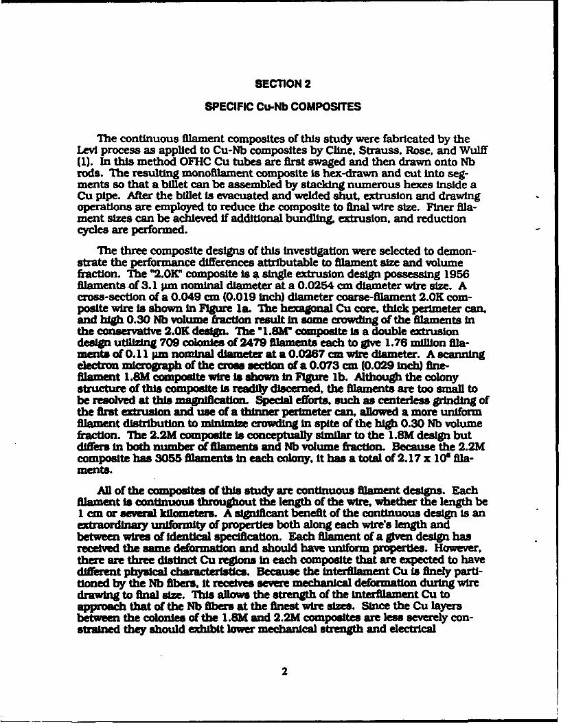
SPECIFIC Cu-Nb COMPOSITES
The continuous filament composites of this study were fabricated by theLevi process as applied to Cu-Nb composites by Cline, Strauss, Rose, and Wulff(1). In this method OFHC Cu tubes are first swaged and then drawn onto Nbrods. The resulting monofliament composite is hex-drawn and cut into seg-ments so that a billet can be assembled by stacking numerous hexes inside aCu pipe. After the billet is evacuated and welded shut, extrusion and drawingoperations are employed to reduce the composite to final wire size. Flner fila-ment sizes can be achieved If additional bundling, extrusion, and reductioncycles are performed.
The three composite designs of this investigation were selected to demon-strate the performance differences attributable to filament size and volumefraction. The "2.01V composite is a single extrusion design possessing 1956filaments of 3.1 un nominal diameter at a 0.0254 cm diameter wire size. Across-section of a 0.049 cm (0.019 inch) diameter coarse-filament 2.0K com-posite wire Is shown in Figure la. The hexagonal Cu core. thick perimeter can.and high 0.30 Nb volume fraction result in some crowding of the filaments inthe conservative 2.0K design. The ".8M" composite is a double extrusiondesign utilizing 709 colonies of 2479 filaments each to give 1.76 million fila-ments of 0.11 urn nominal diameter at a 0.0267 an wire diameter. A scanningelectron micrograph of the cros section of a 0.073 cm (0.029 inch) fine-filament L.SM composite wire Is shown In Figure lb. Although the colonystrcture of this composite is readily discerned, the filaments are too small tobe resolved at this magnifcation Special efforts, such as centerless grinding ofthe first extrusion and use of a thinner perimeter can, allowed a more uniformfilament distribution to minimize crowding In spite of the high 0.30 Nb volumefraction. The 2.2M composite is conceptually similar to the 1.8M design butdiffers in both number of filaments and Nb volume fraction. Because the 2.2Mcomposite has 3055 filaments In each colony. it has a total of 2.17 x 10⁶ fila-ments.
All of the composites of this study are continuous filament designs. Eachfilament is continuous throughout the length of the wire, whether the length beI cm or several kilometers. A significant benefit of the continuou design is anex-Raordinay uniformity of properties both along each wire's length andbetween wires of Identical specification. Each filament of a given design hasreceived the same deformation and should have uniform properties. However.there are three distinct Cu regions in each composite that are expected to havedifferent physical characterist. Because the Interfilament Cu is finely parti-tioned by the Nb fibers, it receives severe mechanical deformation during wiredrawing to final size. This allows the strength of the triaent Cu toapproach that of the Nb fibers at the finest wire sizes. Since the Cu layersbetween the colonies of the 1.SM and 2.2M compoites are less severely con-strained they should exhibit lower mechanical strength and electrical
2

(a)
(b)
Figure 1. Cross-sections of (a) the 2.0K coarse-filament and (b) the1.8M fine-filament Cu-Nb composites of this study. The2.0K wire is derived from a single extrusion billet whereasthe 1.8M material is the result of a double extrusion fabri-cation.
3

resistivity. The Cu in the filament-free perimeter can (and in the center of the2.0K design) should exhibit strengthening and annealing characteristicsapproximating those of heavily deformed bulk OFHC Cu. As such, the perime-ter Cu can is a region of relatively low mechanical strength and high electricalconductivity. This is useful because it both enhances ac electrical conductivityand minimizes notch sensitivity. Because of the differences in filament size,filament count, and Nb volume fraction the three Cu-Nb composites provide abasis for the assessment of design parameters. The specifications of the com-posites are summarized In Table 1.
Table 1. Design parameters for the 2.0K, 1.8M. and 2.2M Cu-Nbcomposite wires.
Composite Designation 2.0K 1.8M 2.2MNumber of Colonies 1 709 709Filaments per Colony 1956 2479 3055Total Number oFilaments 1956 1.76z I0 2.17x 10POverall Nb Volume Fraction 0.30 0.30 0.18Local Nb Volume Fraction 0.45 0.35 0.23Nozmil Fwber Dimeter 3.1 n 0.11 pm 0.07 pm
at 0.0254 cm wie ae
4

SECTION 3
STRENGTH AND RESISTIVITY OF Cu-Nb COMPOSITES
3.1 CONCEPT AND APPROACH.
The two most important parameters for a robust electrical conductor aremechanical strength and electrical resistivity. In particular a high mechanicalstrength and low electrical resistivity are desired. Additionally, any normal-state conductor experiences resistance or Joule heating while carrying a cur-rent. In many environments the available cooling may be Insufficient tomaintain the ambient temperature in the conductor. Therefore, the annealingbehavior of the conductors can be important.
Filamentary composites of continuous Nb fibers in Cu matrices were testedto determine the effect of composite design on ultimate tensile strength andelectrical resistivity. Both coarse and fine filament composites were tested todemonstrate the benefits of microfilamentary composites. Properties weredetermined as a function of wire size to Indicate the strengthening mecha-nisms. Fine-filament wires of various diameters given elevated-temperatureheat treatments were tensile tested to define annealing characteristcs.
3.2 INTRODUCTION.
The strength and annealing characteristics of multifilamentary compositeshave been Investigated in a number of Cu-matrix systems such as Cu-W (2).Cu-Ag (3.4), and Cu-Nb (5,6). However, most studies of fine-filament compos-Ites have been performed on materials fabricated by In-situ methods (3-7) tofacilitate the preparation of fine-filament sizes. The strengths of large filamentdesigns tend to obey the rule of mixtures (2), whereas the tensile values of fine-filament composites often exceed linear combination predictons by large mar-gins In both fcc-fcc (3) and fcc-bce (5) systems. Additionaly, the electricalresstivity has exhibited anomalous effects at the high reductions required toobtain fine fiber s)es (4).
The mechanisms by which the physical properties are enhanced can berevealed by exmining the functonalty of strength and resistIvity increaseswith respect to decreasing wire size. The simultaneous deformation of bcc Nband fcc Cu-neessrily requires some acc mmodation between matrix and fila-ments. Specicaly, the 11101 texture which develops in bec metals (8) resultsin a marked tendency of the Nb filaments to become ribbon shaped in in-situCu-Nb composites (5). Since the partitioning and high dislocaton density inthe matrix result in high Cu restIvities, electrical conductivity is a usefulmeans of observing matrix annealing in these materials. The elevated-temperature results of Karasek and Bevk (6) indicate that even very fine in-situCu-Nb wires are annealed by 525C. Further work on these materials by Bevk,Harbison. and Bell (5) demonstrated ultimate tensile strengths that far exceed
5

the rule of mixtures. Continuous-filament resistivity results of Klein and Rose(9) indicate that the finest composites are not completely annealed until 600"C.By monitoring ultimate tensile strength and electrical resistivity as a functionof Nb volume fraction and wire size the available tradeoffs between mechanicaland electrical properties are to be defined. Examination of annealing behaviorwill indicate suitability for elevated temperature service.
3.3 RESULTS AND DISCUSSION.
Tensile testing of continuous filament Cu-Nb composites was undertakento define the manner in which strength was developed. Of particular interestwere the effects of filament size and Nb volume fraction. Wire samples of thethree composite designs were tensile tested in an Instron 4204 loadfiame untilfailure. The 2.0K and 1.8M wires provide a comparison of coarse and fine fila-ment composites of similar Nb volume fraction. Including both 1.8M and 2.2Mwires provided a basis for assessing the role of Nb volume fraction In determin-ing strength. Wire drawing is a permanent deformation process that reducesthe dimensions of the wire cross-section uniformly. As the diameter of the wiredecreases the distance between the Cu matrix-Nb filament interfaces isreduced. Such reductions In the scale d of the microstructure usually increasethe strength a of a material according to the Hall-Petch relationship (10.11)
k
where a. and k are constants for a given material. To reveal any tendency ofthe data to follow this trend the ultimate tensile strength was plotted as a fimc-tion of root reciprocal wire diameter. The ultimate tensile strengths of the sam-ple wires are noted In FIgure 2. The 2.0K strengths are linear with respect toroot reciprocal wire size tt the diameter range Investigated. Thus, thecoarse-filament 2.0K data can be described well by a Hall-Petch relationship.The fine-flament 1.8M and 2.2M curves exhibit a significantly different behav-ior. As antcipated, the fine-filamentwires are remarkabl stronger than the2.0K wires. In addition, the rate of Increase in strength (the slope) is muchgreater for the fine-filament data. The higher Nb volume fraction 1.8M wiresare stronger than their 2.2M counterparts at simar wire sizes. However. thefine-filament curves are linear only over the first part of the size range. Curvesfor both 1.W and 2.2M wires become parabolic at the finest wire sizes. Itbecomes obvious that other factors are playing a role In sengthening the com-posites.
The deformation Inherent In room temperatur wire drawing Introduces alarge degree of cold work In the composite wires. The major influence of thisdeformation on the microstructure is to Increase dramatically the density of
6

2000 290
1800.- E 261
o 16001 -232
~ 1400030 v/o Nbl1.8M20v. 1200 0 18 v/o Nb 2.2M 174
)1000. A 30 v/o Nb 2.OK 145 ..
800 116
600, 872 4 6 8 10 12 14
FVgur 2. Ultimate tensile strengt as a fuinction of root reciprocalwire size for the coarse-filament 2.0K and fine-filament1.8M and 2.2M Cu-Nb composite wires.
defects. The defects, predominantly crystal lattice distortions called disloca-tions. act to hinder further deformation of the materials. Heavily deformedmaterials such as small wires tend to be strong by virtue of their highdislocation densities. In the present case of Cu-Nb composites both the Nbfilaments and the Cu matrix are known to experience dramatic rises in disloca-tion density as the wires are deformed during drawing. The distortion of themcrostructure inherent In dislocations acts to disrupt electrical conduction.An indication of the dislocatio density in the Cu can be gained by consderingthe electrical resistivity of the wires. Because of the much higher resistivity ofNb, the normal state conductivity of the wires is governed by the Cu matrix.The dependence of the electrical resistivity on reciprocal wire size is shown inFIgure 3. The coarse-filament 2.0K data is fitted by a single straight line indi-cating that electrical resistivity p is gtvm by
KP - dP-P.+ .
The .HM and 2.2M compo have ncant high remtivities at eachwire size. Given Its higher Nb volume fraction, it is expected that the resistivityof the 1.SM composite is grester than that of the 2.2M design at each wire size.The fine-filament curves are initially quite linear but become parabolic at thefinest wire sizes The deviations from linearity occur at the same wire sues asdid the bends in the ultimate tensile strength curves. This suggeat that themecanical strengthening is due to the increased dlocation density. Theexperimental results of Rider and Foxon (12) and the theoretical considerations
7

of Brown (13) suggest that Cu resistivity is directly proportional to dislocationdensity with a Cu dislocation resistivity on the order of 2 x 10"10 Olcmn. There-fore the dislocation density p,. in the linear portion of the Figure 3 curves isgivenby
K,
Noting that the dependence of strength a on dislocation density Is given bya- o. +r4 "p (14). the dependence of strength on wire size becomes
:r,+d ,
which is the Hall-Petch relationship. Thus the strengthening behavior noted inthe Cu-Nb composites of this study is consistent with both the spacing of barri-ers (the Cu matrix-Nb filament interfaces) and the increase in dislocato.A den-slty (form wire drawing deformation).
5.0 0 30 v/o Nb 1.8M
E 4.5- 018v/oNb2.2M4. a 30 v/o Nb 2.OK
.E 3..C0:k 3.0.
S2.5 AAA
2.010 30 60 90 120 150 180
1/d, 1/cm
Flgur 3. ectrcal resistvity as a function of reciprocal wire size forthe coarse-filament 2.0K and fine-M=lamet I.SM and 2.2MCu-Nb cmposite wires.
From an t wpoint Its the tradeoff between strength and elec-trical ca-ductivity that Is most Impxant It is lmprtnt to determine [I]whether REW-filament c prvde a better tradeoff and 121 the Impact ofvolume fraction on the stre gth-conducivity m. These issues areaddresed by Fgure 4 In which electrical comuctivity is plotted as a functioo( ultimate tens stregh For each Composite cdctivity is linear withrespect to uldmde ten somngth. The 1.9M and 2.2M fine filament data aredeser9d by a abnk line. ThM s the of Nb volume frvtion should be
S
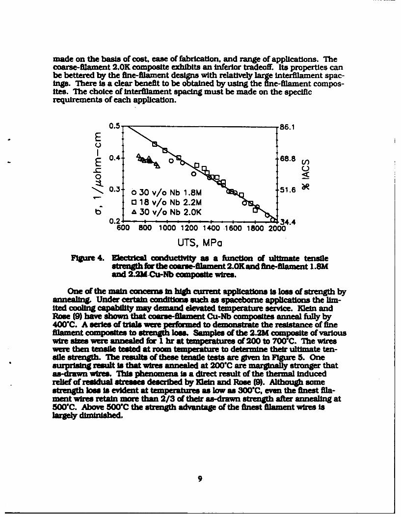
made on the basis of cost, ease of fabrication, and range of applications. Thecoarse-filament 2.0K composite exhibits an inferior tradeoff. Its properties canbe bettered by the fine-filament designs with relatively large Interfilament spac-ings. There Is a clear benefit to be obtained by using the fine-filament compos-ites. The choice of interfilament spacing must be made on the specificrequirements of each application.
0.5 86.1
E
0. 68.8 EE~ 0
0 0<
0.3 0 30 v/o Nb 1.8M 51.60 18 v/o Nb 2.2M
o. A 30 v/o Nb 2.0K0.2' 34.4
600 800 1000 1200 1400 1600 1800 2000
UTS, MPaFgure 4. Electrlcal condu as a function of ultimate tensile
strength for the comare-filament 2.01[ and fine-filament 1.8Mand 2.2M-Cu-Nb composite wir.
One of the main concerns In high current aicatons Is loss of strength byannealing. Under certain conditions such as spacebore applicatons the lim-ited cooling capability may demand elevated tem-rature service. Klein andRose (9) have shown that coarse-filament Cu-Nb composites anneal fully by400C. A series of trials were puformed to demontrate the resistance of finefilament composites to strength loss. Samples of the 2.2M composite of variouswire sizes were annealed for I hr at t of 200 to 70'C. The wireswere then tensile tested at room temperature to determine their ultimate ten-sle strgh The results of these tensile tests are given In Figure 5. OnesurprisI result is that wires annealed at 200"C are marginaRy stronger thatas-drawn wires. bis phenomena is a direct result of the thermal inducedrelief of residual stresses described by Klein and Rose (9). Although somestrength loss is evident at temperatures as low as 300"C. even the finest fila-ment wires retain more than 2/3 of their as-drawn strength after annealing at500"C. Above 500C the strength advantage of the finest filament wires isW1gey m.
9

2000 2902000C18 v/o Nb 2.2M 30o3000 C1600.- 4000C 232
aS1200 174 Vi
I- 7000 CZ) 800 1164 "-I lP ~ il 7000C )
400 583 5 7 9 11 13 15
Figure 5. Ultimate tensile strength as a functon of root reciprocal wiresize for fine-flament 2.2M Cu-Nb composite wires given 1-hrheat treatments at different temperatures.
4 CONCLUSIONShe streg multiamentary Cu-Nb cmnposites with decreasing
wire size Is generally demeribed by a Hall-Petch relaionship o= o.+k4I. Itisikely that the strengthenn occurs through a combination of Interfae barriersand dislocation density. Theresistiity of wvre of different sizes is closelydescribed by p= p.+k. At the smallest sizes o the ne--filament composites therates of Uncrase In rength and resis ty a somewhat dmnshd. In con-sidering the tradeoff between electrical conductivity and mechanical strength.the coarse-filament wires are clearly Inferior. In the fine-ilament wires thestrength-conducUvity tradeoff is simllar over a wide range of Nb volume frac-tion All sizes . the fine-filament composites display excellent resistance tonea at temperatues below 500C. However, the finest micostructures
have relativel little advantage If sustained service at higher temperatures Isanticipated.
10

SECTION 4
ANNEALING BEHAVIOR OF Nb FILAMENTS
4.1 CONCEPT AND APPROACH.
The strength of multlfllamentary composites can be degraded by annealingof matrix and/or filament materials. The annealing behavior of Cu-Nb compos-Ires Is commonly examined by monitoring electrical resistivity. Since Cu is amuch better normal state conductor than Nb, room temperature or elevatedtemperature resistivity cannot reveal thermally induced changes in Nb fila-ments. Although It Is commonly assumed that annealing of the Cu matrix isresponsible for strength loss at service temperatures below 500"C. the smallsize of the Nb filaments suggests that they may also be vulnerable. While Cu isalways a normal state conductor. Nb becomes superconducting at very lowtemperatures. As such, the superconducting properties of Cu-Nb compositesare governed by the Nb filaments. Moreover. the superconducting properties ofNb are strongly Influenced by its deformation conditions. Therefore. the super-conducting properties of Cu-Nb composites given various heat treatmentsshould reveal Nb annealing behavior.
Microfmentary composites of continuous Nb fibers In Cu matrices weretested for superconducting transport properties after heat treatments at 200 to900C. The critical current density at any given applied magnetic field wasreduced dramaticaly as the heat treatment temperature was increased. Thescaling relations describing the critical current as a function of applied fieldshifted from conventional (-hji callng to higher order relations as the heattreatment history was varied. Critical temperature transitions were abnormallybroad In the fine-filament composites exmmined. The upper critical fields andtransitio temperatures approached bulk values after severe heat treatment.
4.2 INTRODUCTION.
The effect of heat treatment on the nonsuperconducting electrical proper-ties of mutil11am ntry Cu-Nb composites has been addressed by severalInvestigations (15,6.9). Since the normal state conductivity of Cu Is so muchgreater than that of Nb. these studles have served largely to Indicate theannealig and Intefacial scatteing behavior of the Cu matrix as constrainedby the Nb filaments. Resistivity studies of Wt-situ composites as a function oftemperature have been purued to Indic the annealng behavior of the Cu(15.6). Resistivity and thermal contraction observations of continuous filamentCu-Nb composites have related matrix aealng behavior to the relief of largeresidual strains InWduced during cold drawing to final wire size (9). However.heat treatment at even moderate temperatures can be expected to alter thep of the small Nb filaments as well as the surrounding Cu matrix. Theeffects o heat treatment on the Cu and Nb can be partially separated by con-sidering the supen behavior of the composites. Since the Cu matrix
II

Is not superconducting the critical current and transition temperature of thecomposites are governed by the properties of the Nb filaments. The presentwork on continuous-filament materials produced by stack-and-draw methodsdescribes superconducting behavior in multifliamentary Cu-Nb composites inwhich there Is little chance of filament contamination by matrix Cu during fab-rication.
The heat treatment of Cu-Nb composite wires might change the supercon-ducting properties by altering either the Cu matrix or the Nb filaments. Super-conducting wires comprised of multifflamentary Nb3Sn in a bronze matrixrespond strongly to their residual stress states at 4.2 K (16,17). Recent •experiments show that annealing cold-drawn Cu-Nb composite wires at tem-peratures as low as 300"C can strongly alter the residual stresses present atroom temperature (9). Additionally, the residual stress state of the Nbfilaments at 4.2 K will be Influenced by the differing thermal contractions of Cuand Nb as well as the possible complication of plastic deformation in anannealed Cu matrix. The effect of heat treatment temperatures up to 900'C onthe internal structure of Nb filaments is not well defined. Moderately deformedNb single crystals have exhibited no thermally activated dislocation motionbelow 1000C (18). Although 900*C is less than half the absolute melting pointof Nb, the coalescence observed in fine-filament Cu-Nb composites (19,20) Indi-cates that major changes can occur within the Nb fibers at much lower temper-atures.
The critical current density, j.. at an applied magnetic field, H, may beenhanced or degraded as the filament size is decreased. At filament diametersgreater than I pm It is generally observed that increasing cold work enhancesthej, of Nb (21). Indeed, this trend as well as an adherence to Kramer (22)scaling was indicated In the magnetization experiments of Mathur. Ashkin. andDeis (23) for Cu-Nb composites having filament diameters of 7 to 18 pm. How-ever, the quadruple extrusion composites of Cline. Strauss, Rose, and Wulff(24) exhibited a decrease nj, as the filament size was taken below 160 rin.This suggests that alternatve scaling relations may be required to describe fluxpinning in these materials. The present study defines Nb filament propertiesas a function of annealing history by Mining the transport and critical tem-perature behavior of coarse-filament and fine-filament Cu-Nb composites givenheat treatents at 200 to 900"C.
4.3 EXPERIMENT.
The continuous filament composites of this study were fabricated by theLevi process as applied to Cu-Nb composites by Cline, Strauss. Rose. and Wulff(25). In this method OFHC Cu tubes are first swaged and drawn onto Nb rods.The resulting mono-ilament composite Is then hex-drawn and cut Into seg-ments so that a billet can be assembled by stacking numerous hexes inside aCu pipe. After the billet is evacuated and welded shut, extrusion and drawingoperations are employed to reduce the composite to final wire size. Finer fila-
12

ment sizes can be achieved if additional bundling, extrusion, and reductioncycles are performed. Two composites designs were used in this investigation.The "2.0K" composite is a single extrusion design possessing 1956 filaments of3.1 pm nominal diameter at a 0.0254 cm diameter wire size. The "1.8m" com-posite Is a double extrusion design utilizing 709 colonies of 2479 filamentseach to give 1.76 million filaments of 0.11 pm nominal diameter at a 0.0267 cmwire diameter.
The dependence of critical current density on applied magnetic field wasmeasured to ascertain the effects of both fine-filament structure and heattreatment on the superconducting properties of Cu-Nb composites. The mea-surements were performed at 4.2 K with a four-point probe arrangement. Theusual IpV/cm transition criterion was used for samples placed In a magneticfield provided by a NbTI superconducting magnet. Most wires were tested at anominal diameter of 0.026 cm in a transverse field through a current densityrange of 10s to I05 amps/cm'. In all cases the field was set before sweepingthe current to obtain a transition.
The critical temperatures of 0.026 cm diameter composites were deter-mined resistively. The specimens were attached to a jig containing a germa-nium cryothermometer by four solder contacts. The jig was then inserted intoa Cu can wound non-Inductively with resistance wire. Placement of the canand jig assembly in a 25 mm quartz tube allowed evacuation by a mechanicalpump prior to the Introduction of a small quantity of He transfer gas. Afterimmersion and equilibratn of the tube In liquid He. currents were applied tothe sample and thermometer. Power was then applied to the heater can togradually drive the sample through Its transition. An overall sample currentdensity of 30 amps/cm= was chosen to provide a better comparison with thecritical current measurements.
4.4 RESULTS AND DISCUSSION.
The superconducting properties of 0.026 cm diameter 2.0K and 1.8MCu-Nb wires were determined In the as-drawn condition as well as after twohour heat treatments performed In a vacuum of better than 2 x 10⁴ Torr attemperatures ranging from 200 to 900-C. The overall critical current densitiesas a function of applied field. j. vs. ,. for the 1.8M composite are shown in Fig-ure 6. As the annealing temperature rises toward 700"C the critical currentcapacity degrades monotonically. The curves for samples heat treated at 701"Cand 798C are essentiafly the same whereas a distinctly different character isexhibited by the sample heat treated at the highest temperature.
The det of the scaling laws appropriate to the 1.8M data wouldallow the definition of the upper critical field m. effective over the critical cur-rent regime Investigated. The shape of the as-drawn 1.8M j. vs. H curve Implies
13

1.8 M, 0.0267cm 0 20*C2 hrs at temperature a 204*C
5. & 304*Cs 0 40"76C
0 4 4- 6064C
70IO
•701"
2
p I I I
0 I 2 3 4 5 6 7 0
Applied Magnetic-Field, kG
FIgure 6. Logarithm of the critical current density (overall r, inamps/cm') as a function of applied magnetic field for fine-filament 1.SM Cu-Nb composites subjected to 2-hour heattreatments at various temperatures.
a rapid reduction of the critical current density as the reduced field t =H/H isincreased. As In the case of ine-flament NbSn data (26). It was found thatsuch behavior failed to fit the Kramer (27) scaling law
F, -J.'Hu=. k,(l-h9.
Here. F, Is the flux pinning force density. j.' is the critical current density in thefilaments and K, is a constant for a gven sample and temperature. The asso-cated (i-h) xapolation function for H is
The higher order -h scaling law employed successfully for the fine-filament
NbsSn data isF,-=J'H -K -h)4 .
. correspondi hiher order extrapolation function becomes
14
As can be seen in Figure 7 the (1-h scaling is much more appropriate than the(1-h? relation for the as-drawn 1.8M wire. Note the linearity of the H, extrapo-lation function as it indicates an upper critical field of 9.55 kG. The failure ofthe more common (1 -h? relation In describing the critical current behavior ofas-drawn Cu-Nb wires Is not surprising. As noted in a discussion of Nb3Snflux pinning by Evetts and Plummer (28). there exist serious reservations con-cerning the applicability of Kramer scaling relations to highly distorted struc-tures. The cold work introduced by drawing to final wire diameter withoutintermediate anneals will produce a high defect density in the Nb filaments.Only after severe annealing will the internal structure of the Nb become moreconsistent with the assumptions of the model.
1.8 M As-drawn
600 30
50 - -25
400 20
300- 15
200 -10
o 0
0 2 4 6 a 10Applied Magnetic Field, kG
FIgure 7. Determination of H, by extrapolation of vriJ7H or "4r to theapplied field axis. Linearity implies that (1-k)' saling isappropriate for this 1.8M as-drawn sample.
The appropriate scaling relation for the 1.8M composites changes at heattreatment temperatures above 650C. The 798 and 901'C data conformstrongly to (1-ii scaling. Plots employed for the H, determination for the 901"Csample are shown in Figure 8. The j, s. it data of this sample conforms closelyto the (1-k? scaling relation. Simillr results hold for the 798"C sample whereasthe 701 C sample conforms to either type of scaling only moderately well. A
15

summary of the scaling parameters of the 0.0267 cm L.8M composite wires Isgiven In Table 2. Further reductions In the 1.8M wire diameter resulted in aloss of critical current capacity. As Indicated In Table 3 the as-drawn wirescontinued to conform to the higher order (1-khr scaling. However, the degrada-tion In j. with decreasing wire size was reflected not only in a reduction of H,,but also in declining values of the slope of the extrapolation plots.
500 1 25
1.8 M, 901C
400- 20
E
IOOO (
a aa
0 ! 2 3 4 5Applied Magnetic Field, kG
Figure 8. ermInation of H.2 by extrapolation of N4Z1T or sji7to the applied field axis. Unearity implies that (1-h?scaling is appropriate for this 1.8M sample heat treatedat 90 1"C for 2 hours.
The overall critical current as a function of applied field results for thecoarse-filament 2.0K composite are only qualitatively similar to those describedabove. The j.vs.H characteristics of 0.0254 cm diameter 2.0K wires given2-hour heat treatments up to 900C are shown In Figure 9. At any given heattreatment condition the critical current capacity of the 2.0K wires Is Inferior tothat exhibited by their I.SM counterparts. The scaling behavior of the coarse-fllamnent 2.0K composites is initially quite different than that shown by thefine-filament wire. The critical current behavior of 2.0K wires In the as-drawncondition and those annealed at temperatures below 450"C Is such that theplot of bo&j, vs. m Is linear over the current density range Investigated. Interme-diate heat treatment temperatures result in j. w. it behavior that can be repre-sented by the (-hf scaling discussed above. As before, the highest heattreatment temperatures yield curves that are consistent with (1-k)2 scaling.
16

Table 2. Values of H,, derived from fitting the 0.0267 cm IS8M , vs. Hdata to (i -A? or (1- hr scaling.
Temperature of A to fit Correlation2-hour anneal F,- K, r-(I -Isr Coefficient .
rC) Of ait (kG)
as-drawn 4 0.9992 9.55204 4 0.9953 9.01304 4 0.9993 7.55407 4 0.9994 6.02504 4 0.96 4.84606 4 0.9985 4.00701 4 0.9951 3.73798 2 0.9994 3.53901 2 0.9996 3.79
Table 3. Values of , derived from fitting . vs.H data of as-drawn 1 .8Mwires of various diameters to (1- ht scaling.
Wile a ato fit CorrelatfondimtrF jr. -41 -,tr Coefficient Ift
1Cm) Offt (KG)
0MOM6 4 0.9974 9.670.0208 4 0.9988 9.010.0170 4 0.9980 8.200.0135 4 0.9949 6.67
This alloved the effective upper field to be deemndreadily for wires givenheat tetmet above 450C. For the wires given less severe heat tz eatmentsthe upper critca field was estimated as the 9 plied field tha would allow anoverall critical current density of 10 amps/cma. This Is consistent with the H.,values obtained from application of the scaling laws to the other wires in thesense that extra polation of their curves gives m., as the applied field at thiscurrent density. The scaling ch-ceitc of the 2.0K wires are noted inTable 4. The data Indicate that H., falls sharply as tMe heat treatment tempera-ture is raised toward 650-C. As was the case with the 1.8M composite, heattreatment of the 2.0K wires above 650C resulted In a limiting value of 3.6 kGfor the upper critical field.
17

o 20PC2.0 K,0.0254 cm a 2041C2 hrs at temperoature & 304"C
E 0 4070C* 504'C
C £606CS4-
*7019C*7989C9-3
-9010C
2-
_ I I I I I I
I a 3 4 5 6 7 6 9
Applied Magnetic Field, kG
Fjgure 9. Logarithm of the eiucal current density (oveall r. inamps/cm) w a function of applied magnetic field forcoarse-flament 2.0K Cu-Nb compoites subjected to 2-hourheat trIetMents at various temperatures.
Table 4. Values of H., derived fm fitting the 0.0254 cm 2.OKi* w. H datato (1-k? or (1-1 scaling.
1mpemtue dA ato At Correlaion2-bow anned Fr, - -w Ca 0- "fat
Of At 09G)in-*awn a " 9.1
204 8 8.7304 a a 7.8407 a a 6.6504 4 0.9996 4.79w.e 4 0.9982 4.07701 2 0.9974 3.37796 2 0.9961 34I901 2 0.9992 3.61
The io&*J. v.H pkpt IsIbmar for theme oamplm
18

The critical temperature T, of a superconductor is often taken as an indica-tor of the quality of the material. As a comparison, a Nb single crystal tested ata current density of 3.0 amps/cm' was found to have a relatively sharpsuperconducting transition starting at 9.15 K and ending at 9.12 K. The 30amps/cm2 T, results for the 1.8M and 2.0K composite wires appear in Figure10. Under all heat treatment conditions examined the transitions for the 2.0Kwires are relatively shexp (< 0.09 K wide) with the transitions occurring in thevicinity of 9 K. Samples of the 2.0K composite given two-hour heat treatmentsat temperatures below 400"C have slightly broadened transitions. Also notableis a significant depression and broadening in the superconducting transitionsof samples heat treated above 750"C. The characteristics of the critical temper-ature transitions of the 1.8M wires are remarkably different. Under all but themost severe heat treatment conditions the transitions are quite broad andappreciably depressed. The effect of heat treatment at temperatures below600"C is to depress the transition temperature while maintaining the breadthof the transition. Heat treatments above 600"C tend to Increase T, and sharpenthe transition.
10C)2.OK 01.8M
U. .M
8*
0. • 0
70 200 400 600 800 1000
Heat Treatment Temperature, °C
Figure 10. Critical temperature as a function of 2-hour heattreatment temperature for 0.0257 cm 2.0K and 0.0267cm 1.8M Cu-Nb composite wires. Squared and circlesdenote the onsets and completions of the transition tothe superconducting state, respectively.
19

4.5 CONCLUSIONS.
The critical current capacity of cold-drawn Cu-Nb multifllamentary com-posites is significantly reduced by heat treatment at temperatures as low as200C. Application of the appropriate scaling laws to the coarse-filament 2.0Kand fine-filament 1.8M data indicates that the reduction is largely the result ofa depression of the effective upper critical field. Shown In Figure 11 are theeffective H.1s governing the critical current behavior of the two composites inthe range of 100 to I05 amps/cm. As the heat treatment temperature wasraised from 200 to 600C H,. was reduced by more than 1 kG for each 100C.Heat treatment at temperatures above 650C allowed the upper critical field toreach a limiting value of about 3.4 to 3.5 kG with some recovery of H, afterannealing at 9000C. In addition, the critical current behavior of the 1.8M wiressubjected to heat treatments above 750"C conformed to the more usual (I-A?scaling.
10
9 *1.8M
8 0 2.0K
-- 70
6534 U30 200 400 600 800 1000
Heat Treatment Temperature, 0 C
Figure 11. The effective upper critical field of 0.026 cm 2.0K and1.SM wires as a function of heat treatment temperature.
The obuerved changes in H, upon annealing would seem to result from acombination of stress rehef, recovery processes, and filament coalescence.Stress effects can expain much of the critical current behavior in wires givenlow temperature heat treatments. The higher tensile strength and lower vol-ume fraction of the Nb filaments as compared to the Cu matrix allows highresidual tensile strains to be introduced in the filaments during cold drawing tofinal wire size. DifferentIal thermal expansion experiments have shown thatthe Nb filaments in the present 0.026 cm diameter composites have residual
20

tensile strains of 0.4 to 0.75 percent at room temperature.s In the as-drawnwires the tensile stress in the Nb filaments Is balanced by compressive stress inthe matrix Cu. However, since there is much more Cu than Nb In these com-posites, the residual compressive stresses In the Cu matrix are of much smallermagnitude than the tensile stresses n the Nb filaments. The higher residualstrain levels are associated with the fine-filament 1.8M composite because thegreater cold work and smaller Interfilament spacings In the fine filament mate-rials produce a stronger Cu matrix. The effect of heat treatment Is to relievethe residual strains by the relatively low temperature annealing of the Cumatrix. Resistivity studies of these composites have shown that 0.026 cmdiameter 2.0K wires are fully annealed by heat treatments at less than 5000C.Fne-filament 1.8M wires of similar diameter experience significant decreases inresistivity beyond 6000C.3
The stress state of the Nb filaments Is particularly Important to the criticalcurrent behavior of Cu-Nb composites. The application of tensile strains to as-drawn or heat treated Cu-Nb composites can drastically enhance the criticalcurrent capacity at 4.2 K according to
lo,,J, = me +b
where e is the applied strain and m and b are constants for a given sample.applied magnetic field, and temperature conditions (29). An applied strain of I% often Increases the critical current capacity by more than an order of magni-tude. This suggests that the effect of the low temperature heat treatments ofthis investigation is to relieve the residual tensile strains in the filaments of theas-drawn wires by permitting relation and annealing of the matrix Cu. Thelower strain In the Nb filaments results In reduced critical current capacitywithout internal structural changes In the filaments. This apparent reductionin the upper critical field with reduced filament tension is consistent with theobservations of Hill and Rose (30) and Klein (26).
The present experimental results indicate that heat treatments performedabove 400C alter the Internal structure of the Nb filaments. The Cu matrix ofthe coarse-filament 2.0K composite will be fully annealed by heat treatments at450C. However, the R, values shown in Figure I I are still decreasing between500 and BOC. In addftion the 2.0K critical temperature transitions describedby Figure 10 are sharpest between 500 and 700"C. Similarly, the sharpnessand midpoint temperature of the 1.8M superconducting transitions increasewith increasing annealing temperature above 500"C. Microscopic examinationof the fine-filament I.SM composite reveals that high temperature heat treat-ments cause the closely spaced filaments to coalesce as shown In Figure 12.Coalescence of the ISM fine-filament colonies would result in large porous"filaments" similar in size to the filaments of the 2.0K composite. This Is Indi-cated by the agreement of the ISM and 2.OK j, Ys. , m., and T, behavior In wiresheat treated above 550"C. The action of rapid Nb recovery processes is furthersupported by electron microscopy of in-situ Cu-Nb composites. Verhoeven.Downing Chumbley. and Gibson have observed the onset of Nb filament coars-
21

eng at temperatur,.a as low as 320"C In fine-filament In-situ composites (15).The ctional dependence of the critical current on the applied field isdetermined by the defect structure responsible for flux pinning. Although (1-hs?scaling is appropriate for wires possessing well annealed Nb filaments, otherrelations such as the (i-h# scaling noted In this investigation are necessary todescribe flux pinning behavior In heavily deformed Nb.
as-drown I - H
(a)
2 hr 0 7000C I5,um r
(b)
FIgure 12. Cross-sections of representative colonies of the .SMdouble extrusion composite are shown (a) In the as-drawn condition and (b) after a two hour heat treat-ment at 700C. Heat treatment has caused the 2479Nb flaments of the as-drawn colony to coalesce intoa sponge-like structure. The matrix Cu has beenetched away to reveal the Nb morphology.
22

SECTION 5
PULSED CURRENT FATIGUE OF Cu-Nb COMPOSITES
5.1 CONCEPT AND APPROACH.
The suitability of multiflHamentary composites of continuous Nb fibers InCu matrices for high stress conductors In pulsed current applications wasassessed by a novel electromechanical testing method described as pulsed cur-rent fatigue. In this technique direct current pulses are applied to a verticallyoriented wire supporting a dead weight Expansion resulting from jouleheating during the pulse and contraction due to convective and radiative cool-ing between pulses causes periodic mechanical loading of the wire during thepulsed current cycling. Plots of fracture stress as a function of logarithm ofnumber of cycles or time serve to define the role of current level, pulse dura-tion. and pulse frequency on the pulsed current life of composite conductors.Flne-filament Cu-Nb composites exhibit pulsed current fatigue performancethat Is markedly superior to that observed in corresponding coarse-filamentmaterials.
5.2 INTRODUCTION.
Many pulsed current a cations require hih stength, hih conductttyelectrical conductor Projected pulse power requirements Include currents Inthe range of klamps to me.amps, repetition rates up to 100 H& and pulsewidths of 100 --09 to 100 milliseconds (31). Apprecable stresses mayarise from Lorentz forces within coiled conductors or from post-pulse recoileffectr. Weight and volume resrictIons Inherent in space and airborne systemsplace a high priority on mechanial strong conductor materials. The pulsedcurrent fatigue method of conductor testing is intended to combine themechanical and thermal trauma that a conductor material might experience Ina pulsed current system. Although the operating environment and service pro-tocol of Implemented pulsed current conductors will be dictated by their spe-cific applications an experimental method was desired to discrimine betweengood and poor conductor materials. A conductor exhibiting superior pulsedcurntfatie behavior will possess a favorable combination of electrical con-ductivity. mechanical stength. and resistance to annealing.
Floe-moment Cu-matrix componstes are pi appealing for pulsedcurrent pplicatims because of their high tensie strengths,- appirecablresistance to anneallng and electrical conductivities approaching that of purecopper. The strength relaionsps, annealing charcteritcs, and elasticmodulus of multifflamentary compo'tes have been determined in a number ofCu-matrix systems such as Cu-W (2). Cu-Ag (3.4). and Cu-Nb (5-7). However.most studies of fine-filament composItes have been performed on materials fab-ricated by in-situ methods (3-7) to facilitate the preparation of fine flalmentaims. The strengths of large filament designs tend to obey the rule of mixtures
23

(2). whereas the tensile properties of fine-filament composites often exceed lin-ear combination predictions by large margins In both fcc-fcc (4) and fcc-bcc (7)systems. The effect of heat treatment on the nonsuperconducting electricalproperties of multlfllamentary Cu-Nb composites has been addressed by sev-eral investigations (6,9.15). Since the normal state conductivity of Cu is somuch greater than that of Nb, these studies have served largely to indicate theannealing and Interfacial scattering behavior of the Cu matrix as constrainedby the Nb filaments. Resistivity and thermal contraction observations of con-tinuous filament Cu-Nb composites have related matrix annealing behavior tothe relief of large residual strains introduced during cold drawing to final wiresize (9). However, heat treatment at even moderate temperatures can beexpected to alter the properties of the small Nb filaments as well as the sur-rounding Cu matrix. The effects of heat treatment on the Cu and Nb werelargely separated by considering the superconducting behavior of thecomposites. Klein and Rose (32) have shown that fine Nb filaments anneal sig-nificantly at temperatures below 400C. The present work on continuous-filament materials produced by stack-and-draw methods describes pulsedcurrent fatigue performance of coarse-filament (3 Am diameter) and fine-filament (<O. 15 pm nominal diameter) Cu-Nb composites.
5.3 EXPERIMENT.
Pulsed current fatigue Is a materials testing technique in which periodicthermal and mechanical loading of a wire specimen is achieved through theapplication of a pulsed current. The ease with which pulsed current fatigue isImplemented can be a by consdering the etal setup shownin Figure 13. The system is designed to applyan axial load to a wire throughwhich current pulses are passed. The wire sample is held vertically betweenthe upper and lower grips. In practice It has proven convenient to fit the uppergrip rigidly to the upper crosshead of a tensile testing loadframe. The lowergrip assembly is comprised of a wire grip, a weight can, and a rod terminatedwith a displacement transducer core. The body of the linear variable displace-ment transformer (LVDI1 transducer is mounted onto the fixed crosshead ofthe tensile loadfIrame. The LVDT allows thermally and me inducedlength changes to be mniored during testing. Current flow through the sam-ple is cmtrolled by a specialy fabricated pulser circuit. During each cycle thepulser supplies a preset direct current for a short time interval, typically 10msec, and no current for the rest of the period. The reference frequencysupplied by the functio generator determines the repetition rate at which thecurrent s ed by the lead-acid battery is applied. An osilloscope and digitalrecorder are used to monitor the current pulsing and length fluctuations simul-taneouS.
Application of a cyclic pulsed current to the sample changes both the tem-perature and stress state of the wire. Due to the high current densitiesemployed, each pulse causes ab joule heating in the current-onportion of the pulse. During the first few cycles there is little heat disspation
24

upper crosshead
function cellIgene.rator I el'F
upper griplead-acid
battery wire sample
r ~ ~ ~ lwJ--'-' er grip
0 digital weight canscope re coroder.O co
vi l vdt
fixed crosshead
Figure 13. A schematic diagram of the experimental setup for pulsedcurrent fatigue testing.
between the pulses because the w trre is only sighty higher thanthe ambient room temperature. As the wire sample heats, convective and radi-ation heat transfer Increase until the temperature rise during the current pulseis balanced by the temperature drop between pulses. However, even after alarge number of cycles the thermal expansion and contraction during a pulseperiod cause the wire to raise and lower the load resulting from the mass of thelower grip-weight can assembly. Therfore, superiposed upon thermalcyligof the wires is a periodic mechanical loading of the same excitationfrequency, that of the pulsed cueit. The combined thermal and stresscycling under the influence of the current pulses leads to a sgnpificant reduc-tion in load carrying capacity of the wie.
The cyclic history of a wire during pulsed current fatigue can be appre-dated by c nsidering Its temperature and stress state as a function of time.The limited travel of the dt transducer precludes following thelength chanes of a wire during warm-up to steady state conditions. However.numerical modeling of pulsed current fatigue allows a complete history to becalculated. Shown In Figure 14 are the calculated curves for temperature andstress during 20 amp, 10 mec, 0 Hz pulsed current fatigue of a 0.0267 cmdiameter 30 vblune % Nb compu te supporting a mass of 1.8 kg. Each pulsecauses apreable heati of the wire, the effect being more pronounced atlonr times due to the increase of wire resistivity with ncreasng temperature.Howeve. since the rate of heat d o increases rapidly with rising tem-perature the avera temperature over a cycle asymptotcally a hes asteady state value. The axial stress in the wire is determined by a combinationf the pulsin codition, the lower grip assembly mass, and the composite
wire's m p. The applicaton of each current pulse changes
25

the free (unladen) length of the wire in response to the temperature rise. Theresulting raising and lowering of the dead weight provides a mechanical distur-bance that Initiates vibration of the wire-weight-can combination as a spring-mass system. For example, in Figure 14 there are more than two stressoscillations for each current pulse. That is, the lower grip assembly "bounces"twice before the next current pulse disturbs the motion. Careful examinationreveals that there is observable attenuation in the amplitude of the secondbounce. Such damping characteristics are more evident under pulse condi-tions causing more severe mechanical loading.
500-
o 400 -58
m o stressq)0200- -29 (
Ln E 0.0267 cm 1.8M, 1.8 kg I)~150 100..1
20 amps, 10 msec, 10 Hz0. 0
0 1 2 3 4 5 6 7
Time, sec
Flure 14. The calculated thermal and stress history of a wire sub-jected to pulsed current fatigue. The parameters of thenumerical simulaton model were set to describe 20 amp.10 mse, 10 Hz pulsing of a 0.0267 cm 1.8M compositesupporting a mass of 1.8 kg.
The interaction of the wire length oscillations with the applied currentpulse is best appreciated by examining the ch in wire length as a functionof time. Shown In FIgure 15a are calculated and experimental curves for wirelength as a function of time at steady state condtmions. In this case a lower gripassembly mass of 0.91 kg was used to load a 0.018 cm wire under 30 amp. 20msec, and 0.75 Hz pulse conditions. The only adjustment of the modelrequired to match the shapes of the experimental and model length curves wasthe addition of a damping factor to account for the attenuation of the oscilla-tions. These pulse conditions are particularly severe in that they cause a tern-perature rise of -p-rcmaately 300C during each pulse. This would result Inan unladen length increase of approximately 0.74 mm during the current-oninterval. However, when the current pulse ends the lower grip assembly Is stillfing. The cooling wire must therefore arrest the downward motion of theload mass. This causes a jerk on the sample wire that excites sinusoidal oscil-lations of the wire-lower grip spring-mass system. The combination of the
26

15710.018 cm 1.8M. 0.9 1 kg30 A, 20 ins, 0.75 HzE 1561
(a) E Ieprmna
Q) 154-
7 8 910
Time, sec
C1000 10000 0.018 cm 1.13M. 0.91 k9
*30 A.20ma.O.75 Hzmodel .
L- C
Q)~
E UQ) temperature
0 1 - - - - - - 07 8 10
Time, sec
FVgur 15. Mwe echanically sevee 30 a=p. 20 nmec, 0.75 Hzt pulsecoditIons applied to a 0.0 18 cm 1 .M wilre cause a) steady
state oscilltions of the wire length correspondin to b) largtem p erature and sbess alcuaina a function of itilme.
27

thermal expansion and the Jerk result in a laden length change of more than1.2 mm under these pulse-load mass conditions. Naturally, the severity of thisJerk Is reflected in the stress history. The length and stress values depicted inFigure 15b were produced by the numerical simulation used to generate themodel length trace shown in Figure 15a. Close examination of the stress curvereveals that the initial drop in stress associated with the current-on thermalexpansion is followed by a sharp increase associated with arresting the down-ward motion of the load mass. The peak-to-peak amplitude of the stress oscil-lations, 620 MPa. is more than 1.8 times the mean stress of 340 MPa. Underthese conditions the stress ranges from 670 MPa to 50 MPa during each pulseperiod. Note also that the time of maximum tensile stress is nearly coincidentwith the time of maximum temperature. Since increases in the severity of thepulse will raise both the peak temperature and the peak tensile stress, conduc-tor life should be remarkably sensitive to pulse conditions.
.4 RESULTS AND DISCUSSION.
The pulsed current fatigue method of conductor evaluation was devised toassess the relative performance of candidate high strength electrical conduc-tors In pulsed current applications. The variables Inherent in pulsed currentfatigue testing can be separated into conductor parameters and current pulsingcharacteristics. The ability of the test to discrimite between candidate con-ductors is demonstrated by eamining the relative performance of two compos-ite wire designs differing mainly in filament size. The sensitivity of a conductorto the severity of a current pulse was examined by applying pulse conditions ofsimilar average power but different pulse energy to the better conductor.
5.4.1 Fiament Size Effects.
The coarse-filament 2.0K Cu-Nb composite was considered as a mediumstrength material obeying the rule of mixtures with respect to both mechanicaland electrical properties. At room temperature a 0.0254 cm 2.0K wire has anelectrical resistivity of 2.47 pohm-cm, a yield strength of 525 MPa (76 ks). anultimate tensile strength of 785 MPa (114 ks). and an elongation of 4.0 % overa 10 cm gage length. Since high performance applications are of particularinterest, relatively large currents were applied to small wires. The pulsed cur-rent fatigue behavior of the 0.0254 cm 2.0K composite wires was determinedwith 10 me=c, 10 Hz direct current pulses. The 15 and 20 amp current levelsemployed correspond to overall current densities of 3 x 10 and 4 x 10⁴amps/cm2 , respectively. As is usually the case with materials exposed to cyclictrauma the number of cycles to failure is strongly dependent on the stress lev-els employed. Representation of all the data on a single graph requires semilogaxes as shown in Figure 16. The vertical aids Is the static stress obtained bydividing the weight of the lower grip assembly by the cross-sectional area of thewire. The horizontal axis Is the number of pulse cycles to failure plotteda-cording to logarithmic graduations. The 15 and 20 amp curves have similarshapes consisting of two well-defined segments. each of which appears approxi-mately linear on a semilog plot. The initial sharp drop of static stress with
28

Increasing number of pulse cycles is attributed to the transient temperaturerise to steady-state conditions. During this period the warming of the wirereduces its tensile strength until the load applied by the dead weight results Inan overload condition. After reaching a steady state average temperature thewires are subjected to a combination of cyclic mechanical loading and creep.Under these conditions the wire gradually degrades through accumu-lated annealing and mechanical damage. In comparing the two curves of Fig-ure 16 It should be remembered that the joule heating input at the 20 amplevel Is approximately 1.8 times that at the 15 amp condition. Actually. thedifference is probably greater due to the Increase in resistivity at elevated tem-peratures.
1000 1450.0257 cm 2.0K
0~scl~ 0 15 ampsM . 10 msec, 10 Hz
0 20amps
.50 050 b 20 omps ._7
(13
0 2 010 10 2 10 10 4 10 5 10 6
Number of Cycles
FIgure 16. Pulsed current fatigue results of 0.0257 cm 2.0K wiresresulting from 10 msec, 10 Hz pulsing at 15 and 20 amps.
The 1.8M composite wires possess outstanding tensile properties as aresult of their fine-filament structure. For example, a 0.0267 cm 1.8M wire hasa yield strength of 765 MPa (I 11 ksi) and a tensile strength of 1360 MPa (197k}l) with a 3.8 percent elongation relative to a 10 cm gage length. The onlydrawback of fine-filament designs with respect to conductor applications lies insome compomlse of electrical properties. The 2.98 plohm-cm electricalresistivity of an as-drawn 0.0267 cm diameter 1.8M wire is 1.2 times that of a2.0K wire having a similar Nb volume fraction. As such, the application ofsimilar cunrt pulses to the 2.0K and 1.8M wires of the same diameter willcause more heating In the fine-filament composite. In spite of this, the pulsedcurrent fatigue performance of the 1.8M wires is markedly superior to that ofthe 2.0K wires. As shown in FIgure 17, 0.0267 cm diameter L.SM wires canstill support a static stress of 1050 MPa (152 ksl) after ten thousand cycles of15 amp, 10 msec, 10 Hz pulsed current fatigue. This Is more than twice thestress that the 2.0K wires can bear under the same pulse conditions. Thesuperiority of the fine-filament material is even greater under more severe
29
pulse conditions. The 1.8M wires have a fracture stress of more than 600 MPa(87 ksl) after ten thousand cycles of 20 amp, 10 msec, 10 Hz pulsed currentfatigue. The 2.0K data Indicates a fracture stress of less than 200 MPa undersimilar conditions. The much more severe 25 amp. 10 msec. 10 Hz pulse con-ditions result n 1.8M fracture stresses of less than 300 MPa at long times.The average steady state temperature calculated is apparently too high forsustained high stress operation.
2000- 2900.0267 cm 1.8M O 15 amps
0 10 msec, 10 Hz 0 20 amps 218M3 1500. 218 (nA 25 amps
01'000' 0. 145iI.
o500 73UI)
0 i _1 01 10 102 1604 05
Number of CyclesFigure 17. Pulsed current fatigue results of 0.0267 cm 1.SM wires
resulting from 10 msec, 10 Hz pulsing at 15, 20, and 25amps.
5.4.2 Pulse Energy Effects.
The cycli mechancal loading Inherent In pulsed current fatigue arisesfrom the arresting action of the sample wire on the downward motion of thelower grip mass immediately after the end of a pulse. The severity of the post-pulse Jerk is governed by the sharpness with which the wires are heated duringa pulse. During the application of a direct current pulse the temperature riseand hence the unladen length of the wire will be nearly linear with respect totime. That Is. direct current heating tends to extend a conductor at constantvelocity. However, the vertical drop of an unsupported lower grip assemblywould vary as the square of time under the influence of gravity. A low currentpulse results In a low heating rate that allows the descending lower grip assem-bly to keep up with the extending wire. A long pulse, even one of high current.eventually allows the accelerating lower grip assembly to catch up to theextending wire. Generation of the most severe loading therefore requires rapidheating of the sample wire over a short time interval. Smaller diameter fine-Rlament wires provide a means of achieving pulsed current fatigue conditionsof great mechanical severity at readily attainable current levels.
30

The selection of the 1.8M composite design for the pulse energy trials wasdue to the superior performance of the fine-filament composite In the previoussection. The mechanical and electrical properties of the 1.8M wires are notice-ably dependent upon wire :11ameter. Smaller wires have reduced interfilamentspacings that enhance tensile properties at some expense of electricalconductivity. For example, as-drawn 0.018 cm diameter 1.8M wires have ayield strength of 864 MPa (125 ksi), a tensile strength of 1680 MPa (244 ksi),an elongation of 5.3 % (over a 10 cm gage length). and an electrical resistivity of3.01 pohm-cm. To demonstrate the Influence of mechanical severity on pulsedcurrent fatigue behavior three pulse conditions possessing similar heatingcharacteristics were selected. The average temperature of a wire Is primarilydependent on the power that must be dissipated. The average power P. over apulse cycle is given by
P12t plT A
where I is the current during the pulse, t is the duration of the pulse. T is theperiod of the pulse cycle and p, 1. and A are the resistivity. length. and cross-sectional area of the wire. Here. it is assumed that the variations of resistivity.length, and area with temperature and loading are represented by appropriateaverage values. Noting that the period of the pulse cycle T is simply the reci-procal of the pulse frequency, the dependence of the average power on thepulsing conditions becomes
P. a 12 tv
where v is the frequency. In comparison, the energy per pulse does not dependon the frequency of pulsing. Once again ignoring variations In length, areaand resistivity, the dependence of pulse energy
E ai 2 t
is governed by the current and duration of the pulse. The three pulse condi-tions given in Table 5 were chosen to share the same i'ev while differing InE a 2t. Note that the three sets of pulse conditions differ in frequency as well ascurrent and duration. The best comparison between pulsed current conditionsof similr average power but different frequency is provided by plotting theexperimental static stress values as a function of time rather than number ofcycles. As before a logarithmic scale for the abscissa allows all the data to beshown on a single plot. As shown In Figure 18, the differences In pulse energyresult in large variations in the ability to bear stress. Under the least severe 10amps. 10 msec, 13.5 Hz pulse conditions (lt a 1 aml-sec) a static stress of970 MPa can be supported for one thousand seconds. As ,2t i increased to 6and IS amp-sec the maximum static stress at a thousand seconds is reducedto 575 MPa and 250 MPa, respectively. Two factors are important n producing
31
this dramatic sensitivity to pulse energy,. maximum stress and peak tempera-ture. The length and stress oscillations shown in Figures 15a and 15b wereobtained for the 350 MPa static stress point of the 30 amp. 20 msec. 0.75 Hz(18 amp-sec) data. It is Interesting to note that the maximum dynamic stressattained under these high pulse energy conditions is less than the static stressthat can be supported under the lowest pulse energy conditions. Even thoughthe stress oscillations are quite severe, the peak value of 671 MPa is far belowthe static stress levels sustainable under the 10 amp, 10 msec. 13.5 Hz pulseconditions. However, although the average wire temperature Is nearly thesame under the three pulse conditions, the maximum wire temperatures differgreatly.
2000. 2900 10 A, 10 ms, 13.5 Hz
0 [0 20 A, 15 ins, 2.25 Hzn 1500218 U)1500 30 A. 20 ms, 0.75 Hz
q1000 145U/) 0 Q
V) 0.018 cm 1.8M
1 10 100 1000 10,0000
Time, secFigure 18. Pulsed current fatigue results of 0.018 cm 1.8M wires
resulting from three pulse current fatigue conditionshaving the same average power input The lifetime of theconductors Is reduced sharply as the pulse energy Isincreased.
Table 5. Pulsing conditions, 12tv. and 1Ou applied to 0.018 cm diameter1.SM wires.
current !. dumratlo. frequmneyv. J. 12tv, 12t.(amps) (maec) OW (amps/an') (amnp' (amp'-aec
10 10 3.5 38.900 13.5 120 15 2.25 77.700 13.5 630 20 0.75 116.000 13.5 18
32

Fracture surfaces demonstrate the differences in failure mode observed inpulsed current fatigue testing. The initial steeply downward segments of thecurves in Figures 16, 17, and 18 are attributed to overload conditions. As theaverage temperature of a wire approaches a steady-state value Its ultimate ten-sile strength is reduced. When the ultimate tensile strength Is reduced to thelevel of the applied stress, the wire fails. Since all of the wires of thisinvestigation are ductile at room temperature, their failure by tensile overloadshould produce a ductile fracture. As shown in Figure 19a, the fracture sur-face obtained under such conditions exhibits a ductile cup-and-cone morphol-ogy in which the exterior shear IUps surround a dimpled concave interior. Thisparticular fracture was obtained from the initial pulsing of a 0.018 cm diameter1.8M wire under high current density conditions. The ductility is quiteremarkable when the high tensile strength of the conductor is considered. Thelower loads required to extend sample life beyond 100 cycles correspond tostatic stresses considerably less than the tensile strength. As expected, thelong-cycle fracture surface shown in Figure 19b indicates failure by a less duc-tile mechanism. Themost obvious difference is the near 45" inclination of thefracture surface to the axis of the wire. This suggests that shear deformation isan important factor in the failure mode. The fracture surface is comprised ofthree relatively distinct areas: the rim and two interior zones. The perimeter ofthe 1.8M composite is comprised of a filament-free zone of low strength andpoor resistance to annealing. The ductility of the perimeter Cu layer is evi-denced by several cracks or tears around the rim. In contrast, the interiorfilament-laden high strength region exhibits a much less ductile mode offailure. The darkened portion of the interior near the top of the micrographshows a reglon that had been exposed before the fracture of the wire. Thelarger, lighter interior region is characteristic of essentially brittle failure ema-nating from the previously exposed Interior zone. The failure probably startedby the exposure of the Interior colony structure by shearing of the filament-freeouter layer. A gradual progression of the crack into the Interior resulted in thedarkened region. The resulting overload and stress concentration caused frac-ture of the remaining cross-section.
5.5 CONCLU SONS.
A novel test method called pulsed current fatigue was developed to evaluatepotential pulsed current conductors. In this technique a periodic pulsed cur-rent Is applied to a sample conductor wire -prting a dead weight againstthe acceleratn of gravity. The thermal e o resulting from joule heatingof the wire causes cyclic mec.hancal loading along the axis of the wire. Therapid expansion and contraction caused by the thermal cycling introduce oscil-lations of the wire-weight spring-mass system The pulsed urrent fatigue per-formance of fine-filament Cu-Nb composites were found to be markedlysuperior to that of their coarse-filament counterparts. By comparing differentpulse conditions having the same average power Input, it was shown that amore severe pulse can drastically reduce the load mass that can be supportedfor a given time.
33
(a)
(b)
Figure 19. Fracture surfaces of 0.018 cm I.8M Wires subjected toa) 10 amp, 10 msec, 13.5 Hz. 1380 M[Pa and b) 30 amp,20 msec. 0.75 Hz. 345 MPa pulsed current fatigue.
34

SECTION 6
Cu-Ag COMPOSITES
6.1 CONCEPT AND APPROACH.
The multlf lamentary composites of this study are intended to obtain thebest combination of high mechanical strength and low electrical resistivity. Inthe case of the Cu-Nb composites of the proceeding sections both the Nb fila-ments and the Cu matrix contribute to their rmarkale mechanical strength.However, because Nb has such a high resistivity only the Cu matrix providesan effective path for electrical conduction. Electrically, the Nb filaments canalmost be considered as insulators. The substitution of a high conductivityfiber metal for Nb should significantly enhance the electrical performance ofmultiftlamentary composites.
The choice of an alternative filament material must be made on the basis ofmechanical strength, electrical resistivity, and phase diagram limitations. Thehigh mechanical strength of Cu-Nb compsites Is derived from work hardeningof fibers and matrix and the deformation mismatch between Cu and Nb. Toretain these ste n mechanisms the fiber material must be amenable tocold work without annealing and crystallographicalny dissimilla to the Cumatrix. High electrical conductivity requires the use of a semi-noble or noblemetal for the fiber phase. The basic phase diagram limitation is that no brittlephases be formed during billet fabrication The best cmnp mIse betweenthese factors and cost Is provided by employing Ag as the fiber phase. Ag hasexcellent ductility, higher electrical conductivity than Cu. and favorable Cu-Agphase diagram relatonships. The only apparent drawback Is the crystallo-graphic silahrty to Cu. Since both Cu and Ag are face-centered metals, theydiffer crystallographicay only In lattice parameter. However, Frommeyer andWamssrmann (3.4) have fabrticated high strength Cu-Ag wires using an ft-situprocess. This section describes the first investigation of continuous-filamentCu-Ag composites.
6.2 SPECIFIC Cu-Ag COMPOTES.
The n3bufilamentary Cu-Ag compostes of this study were fabricated In-house by WC Laboratorles. Because continuous-filament Cu-Ag compositeshad not been fabricated preiously. an ntentnaly servative design wasdevised. Sub-micron filament diameters were obtained by using a double-extruion fabrication process. The first-extrusIon "I.2K" composite design has1191 filaments of 4.2 pm nominal diameter at a 0.0254 cm diameter wire size.A cros-section of a 0.195 cm (0.077 Inch) diameter coarse-filament 1.2K com-posite wire is shown in Fgure 20a. The thick perimeter can and hgh 0.32 Agvolume fraction result in some crowding of the filaments In the 1.2K design.The double-exusIo "1.3M" composite design utilizes 1115 colonies of the1.2K composite to give 1.33 million filaments of 0.11 ptm nominal diameter at a
35

"00...--. 10 . 0 .. ..
ON3 fiefiaet NuA cmoie ftissuh1.2K wlr is derved froma s/ng~-xrso b.le 0hrathe~~~~~~~a* 1.3 maer. -s th eutofadul-xtulnlr/cat/on. -----
a309

0.0254 cm wire diameter. A scanning electron micrograph of a portion of thecross section of a 0.073 cm (0.029 inch) fine-filament 1.3M composite wire isshown in FIgure 20b. Because of the conservative design of the 1.2K compositewire feedstock used to stack the 1.3M billet there is a thick filament-free Curegion between the colonies. This necessarily results In some compromise ofstrength because a significant portion of the Cu matrix does not benefit fromthe presence of the reinforcing filaments. Special efforts, such as centerlessgrinding of the first extrusion and use of a thinner perimeter can, would allowa more uniform filament distribution.
Both of the Cu-Ag composites of this study are continuous filamentdesigns. Each filament extends throughout the length of the wire, whether thelength be I cm or several kilometers. A significant benefit of the continuousdesign Is an extraordinary uniformity of properties both along each wire'slength and between wires of Identical specification. Each filament of a givendesign has received the same deformation and should have uniform properties.However, there are three distinct Cu regions in the 1.3M composite that areexpected to have different physical characteristics. Because the interfilamentCu is finely partitioned by the Ag fibers, it receives severe mechanical deforma-tion during wire drawing to final size. This allows the strength of the interfila-ment Cu to increase rapidly as the deformation proceeds. Sinee thefilament-free Cu between the colonies and in the perimeter can of the 1.3Mcomposite Is less severely constrained, it will exhibit lower mechanicalstrength, The specifications of the composites are summarzed in Table 6.
Table 6. Design parameters for the 1.2K and 1.3M Cu-Ag compositewires.
Canpst Den~gnation 1.2K LSMWNumber olCok 1 1115Fllisper Colny 1191 1191Total Nunber oFllmtmmu 1191 1.33 10Overall Ag Volume Fhcton 0.32 0.23Local Nb Volume Frctin 0.44 0.44Naal Fler Djrneterat 0.054 em wke Mw 4.2 pam 0.11 in
6.3 RESULTS AND DISCUSSION.
Sinc the 1.3M Cu-Ag composite Is intended to be an Improvement over thefine-filament Cu-Nb designs. it is natural to compare its mechanical and elec-trical properties to those of the 1.8M and 2.2M wires. The ultimate tensilestrength of the 1.3M Cu-Ag. 1.8M Cu-Nb, and 2.2M Cu-Nb compoites areshown as a function of root reciprocal wire diameter in FIgure 21. At all wire
37

sizes the Cu-Ag composite is weaker than its Cu-Nb counterparts. This is aresult of three factors. Since Ag is inherently weaker than Nb. the initialstrength of the Cu-Ag composite is less than that of the Cu-Nb wires. Addition-ally, the uneven filament distribution across the Cu-Ag composite leaves a sub-stantial portion of the cross-section unrelnforced. The lower slope of the Cu-Agcurve of FIgure 21 indicates that the crystallographic similarity of Ag and Cuprovides a strengthening m that is less rapid than that inherent InCu-Nb wires.
2000 290
1800. 0 1.8M Cu-Nb '' 261
1600- -232CL (
S1400 203 -3; . & 1.3M Cu-Ag
v/) 12001 174 /:D 1000, 145
8001 116
600 - - 872 4 6 8 10 12 14
FIgure 21. Ultimate tenale strength as a function of root reciprocalwire size for the fine filament 1.3M Cu-Ag. 1.8M Cu-Nb,and 2.2M Cu-Nb composite wires.
The Cu-Ag composite was fabricated to benefit from the high electrical con-ductivity of Ag. Since the resistivity of Ag Is actually less than that of Cu. theCu-Ag wires should enjoy an appreciable resistivity advantage over the Cu-Nbsamples. The resistivity of each of the three compotes as a fimction of reci-procal wire size is shown In Figure 22. For all wire slzes Investigated, theresistivity of the 1.3M Cu-Ag composite is less than those of the Cu-NbcompoMtes. foreover, the linearity of the Cu-Ag pw.Vd plot prevails over theentire size ran Inve eted. At the largest wire sizes the resistivity benefitsare essentially those expected by the replacement of the resistive Nb with con-ductive Ag. That Is. the large diameter 2.2M wires are approximately 20% andthe L.SM wire are more than 30% more resistive than the Cu-Ag wires. At thesmaller wire sizes (higiher Id values) the disparity Is even more pronounced.this Implies that the dislocation density increases less rapidly in the Cu-Agcompostes than In the Cu-Nb wres. Nb seems to be a significantly moreaggrMMiv reinforcing phase than Is Ag. T1hi is not x gWen the simi-larity of the Cu and Ag face-centered lattices. However. the fact that the linear-
38

Ity of the Cu-Ag plot extends to the finest wire sizes suggests that the 1.3Mcomposite could be drawn to finer Interfilament spacings than were possiblewith the Cu-Nb wires.
5.045-0 1.8M Cu-Nb
4.5 0 2.2Mu
E 4.01 3.5
- 3.0
:t 2.5--
2.0.
0 30 60 90 120 150 180
1/d, 1/cm
Rpgue 22. Electrical resistivity as a function of reciprocal wire sizefor the fine filament 1.3M Cu-Ag 1.SM Cu-Nb. and 2.2MCu-Nb compoit wires.
The deformation Inherent In room temperature wire drawing Introduces alarye degree of cold work in the composite wires. The major Influence of thisde- - -tMo on the microstructure Is to increase dramatically the density ofdefects. The defects, predominantly crystal lattice distortions called disloca-tions. act to hinder further defomation of the materials. Heavily deformedmaterials such as small wires tend to be strong by virtue of a their highdislocation densities. In the present case of fine-filament composites both thefilaments and the matrix are known to experience dramatic rises In dislocationdensity as the wires are deformed during drawing The distortion of the micro-structure Inherent in dislocations acts to disrupt electrical coutin -on. AnIndication of the d density in the Cu can be gaied by csidering theelectical resistivity of the wires. The lower slope of the Cu-Ag line in Figure 22can only partially be explained by the higher electrical ducttvity of the Ag.This Indicates that the closer match In matrix-filament deformation Inherent Inthe Cu-Ag system produces a lower work hardening rate than that which pre-vails in the case of Cu-Nb. This does not mean that high strengths cannot beattained In the Cu-Ag system. It does Imply that more deformation and finerfilament sizes are required to access the highest strength levels.
The fne-flament 1.2K data Is fitted by a single straight line Indicating thatelectrical resistivity is gien by
39

k
The experimental results of Rider and Foxon (12) and the theoretical consider-ations of Brown (13) suggest that Cu resistivity is directly proportional to dislo-cation density with a Cu dislocation resistivity on the order of 2 x 10" rcm.Therefore the dislocation density in the Cu-Ag curve of Figure 22 curve Is givenby
Noting that the dependence of strength on dislocation density is given bya-a, +kpJ;- (14), the dependence of strength on wire size becomes
k
which is the Hall-Petch relationship. Thus the strengthening behavior noted inthe Cu-Ag composites of this study Is consistent with both the spacing of barri-ers (the Cu matrix-Ag filament Interfaces) and the increase i dislocation den-sity (form wire drawing deformation).
From an applications vi t, It is the tradeoff between strength andelectrical conductivity that is most important It is Important to determinewhether fine-filament Cu-Ag composites provide a better tradeoff than theirCu-Nb counterparts. This Is addressed by Figure 23 in which the electricalconductivitles of the three fine-flament composites are plotted as a function ofultimate tensile strengths. For each composite conductivity is linear withrespect to ultimate tensile strength. However, the 1.3M Cu-Ag line cearly liesabove the single line fitting the l.SM and 2.2M Cu-Nb data. Thus, the Ag fla-ments do provide a better conductIvity-strength combiaion. The extra-polatlon of the Cu-Ag data to higher strength levels Indicates that theadvantage should Increase as the strngth Increases.
6.4 CONCLUSION.
The hstreigtenz, o fine-filament Cu-Ag composites with decreasing wiresize is deseribed by a Hali-Petch (10.11) relationsh1p oa,+k4. It is Ikely thatthe strezngening occurs through a combination of Interface barriers and dislo-cation density. The resistivity of wire of different sizes is clely described byp -p. +kd. In considering the tradeoff between electrical conductivity andmechanical strength, the fine-filament Cu-Ag wires are clearly superior to theirCu-Nb e ra . However, the strengthening provided by the Ag filamentsis apparently not as rapid as that observed In Cu-Nb composites. Although theconservatve 1.3M design did not provide access to the highest strength levels.the path to higher Cu-Ag strength is evident. By scorporating some relatively
40

0.55- 94.7
E 0.0--a 1.3M Cu-Ag -86.1
1 0.45---7 .E V
0.30 0 1 8M Cu-N -51.6
0.25- 02.2MCu-b -43.0
0.20 34.4600 800 1000 1200 1400 1600 1800 2000
UTS, MPa
Figure 23. Electrical conductivity as a function of ultimate tensilestrength for the fine-filament, 1UM Cu-Ag. 1 .M Cu-Nb,and 2.2M Cu-Nb composite wires.
stralghtformwl steps In the fabdcationprocess the distribution of filaments can be mademuch more uniform. This wi Wxend the fine-flBIment strengthening mechanism to theentire composite cross-section. Additonaly, the utilization of finer sized Ag in the initialbillet wi alow finer Interfilainent spacings to be accessed at larger composite dame-ter& The fact that the Cu-Ag stngth and resistivty curves show no tendency to satu-rate Indicates that more strengthening would be available In a second-generationcomposite.
41

SECTION 7
RECOMMENDATIONS
The mechanical and electrical properties of continuous-filament Cu-Nb andCu-Ag composites have been surveyed. The microfilamentary Cu-Nb compos-ites were found to have excellent mechanical strength, good electrical conduc-tivity, substantial resistance to annealing, and remarkable pulsed currentfatigue capabilities. As such, the fine-filament Cu-Nb composites should beconsidered as an excellent material for high strength electrical conductors.They could be employed in wire. rod, or plate form. Consideration ofcontinuous-filament Cu-Nb composites as monolithic load-bearing memberswould necessitate the characterization of a large-scale composite in which finefilament sizes were available in rod or plate rather than wire form. Naturally. amore complete characterization of electrical and mechanical properties wouldbe required for specific applications. For example, the transverse properties ofthese materials have not yet been determined.
The Cu-Ag composites present an interesting alternative to the Cu-Nb sys-tem. The anticipated electrical conductivity advantage afforded by Ag filaments.was confirmed. Indeed, extrapolation of their conductivity vs. strengthbehavior indicates that the advantage of Cu-Ag over Cu-Nb will Increase at thehigher strength levels. However, since Ag Is not as aggressive as Nb withregard to developing strength by cold work, the strengths of the present Cu-Agwires do not approach those of the best Cu-Nb samples. Although the presentdata suggests that higher strength levels can be accessed, a second-generationCu-Ag composite program would be required for demonstration.
42

SECTION 8
UIST OF REFERENCES
1. H.E. Cline, B. Strauss. R;M. Rose, and J. Wulif Trans. Q. 52, 132 (1966).2. D.L. McDanels. R.W. Jech, and J.W. Weeton, Trans. AIME =,. 636
(1965).3. G. Fronmmeyer and G. Wassermann, Acta Metall. 23, 1353 (1975).4. G. Frommeyer and G. Wassermann, Phys. Status Solidi 2Z,99 (1975).5. J. Bevk. J.P. Harbison. and J.L Bell J. Appi. Phys. A2. 6031 (1978).6. K.R. Karasek and J. Bevk. J. Appi. Phys. =2. 1370 (1981).7. D.E. Cohen and J. Bevk. Appi. Phys. Lett. 32. 595 (1981).8. W.F. Hosford. Trans. AIME =~. 12 (1964).9. J.D. Klein and R.M. Rose J. Appi. Phys. fil. 2212 (1987).
10. B.O. Hall, Proc.Phys. Soc. B f. 747 (195 1).11. N.J. Petch. J. Iron Steel Inst. In, 25 (1953).12. J.G. Rider and C.T.B. Foxon, Philos. Mag. J&i 1133 (1967).13. [RA Brown, J. Phys. F L. 1283 (1977).14. K.M. Ralls. T.H. Courtney. and J. Wulff, Irefrriction to Materials Science
and Engbnetn (John Wiley & Sons. New York. 1976). p. 450.15. J.D. Verhoeven, H.L Downing. LS. Chumbley and E.D. Gibson. J. Appl.
Ptiys. Md. 1293 (1989).16. J.W. Ein. Adv. in Cryo. Eng. 2A. 306 (1978).17. C.C. Koch and D.S. Easton. Cryogenics IL 391 (1977).18. W. Schiump, H. Freyhart. and E. Nembach, Acta. Met 2&. 257 (1972).19. R. Borrnann, J. Appi. Phys. 5L. 1479 (1983).20. J.D. Verboeven. E.D. Gibson. F.C. Laas J.E. Ostenson. and D.K. FInne-
more. IEETrans. Mag. MAG- 19 563 (1983).21. A.T. Santhanam. J. Mat Scd. 11 1099 (1976).22. E.J. Kramer. J. Appi. Phys. ". 1360 (1973).23. M.P. Mathur. M. AskIn. and D.W. Deis. J. Appi. Phys. A 3627 (1974).24. H.E. Cline, B.P. Strauss, R.M. Rose, and J. Wulff. J. Appl. Phys. 3Z 5
(1986).25. H.E. Cline. B. Strauss, R.M. Rose, and J. Wulff. Transactions Quarterly
A% 132 (1966).
43

26. J.D. Mein, Sc.D. Thesis, Department of Materials Science and Engineer-ngM.I.T., Cambridge. MA (1984).
27. E.J. Iramer, J. Electron. Mater. , 839 (1975).28. J.E. Evetts and C.J.G. Plummer in Proceedings ofInternatlonal Sympo-
sium on Flux Pinning and Electromagnetic Properties in Superconductors.ed. T. Matsushita. KL Yarafuji, and F. Ile (Matsukuma Press, Fukuoka),p. 146.
29. J.D. Klein and R.M. Rose, J. Appl. Phys. f6l. 2979 (1987).30. D.C. Hill and RM. Rose, Met. Trans. 2. 1433 (1971).31. Innovative Science and Techrnology Office bulletin on the Technical Pro-
gramn Information of the Strategic Defense Initiative Organization (1988).32. J.D. lein and K.M. Rose, J. Appl. Phys. f. 930 (1990).
44

APPENDIX A
IPRSONNEL
Several staff and senior personnel aided in the completion of this research proj-ect. The experimental laboratory work was performed by Mr. Allen Yen and Mr.Louis L Wu. Experimental design. composite design, and technical reportingwere undertaken by Dr. James D. Klein. Dr. Stuart F. Cogan was responsiblefor overall progrm management.
The resumes of Drs. James D. Klein and Stuart F. Cogan follow.
45
46

DR. JAMES D. KLEINSenior Materials ScientistEIC Laboratories, Inc.
B.S.E. Mechanical Engineering, Duke University, 1974.M.S. Materials Science, Duke University, 1976.Sc.D. Materials Science. Massachusetts Institute of Technology. 1984.
profesiom Eerenee:
1987-Present Senior Scientist in Materials Research, EIC Laboratories, Inc.1984-1987 Assistant Professor, Department of Metallurgical Engineering.
Michigan Technological University.1979-1984 Research Assistant, Department of Materials Science and
Engieering. Massachusetts Institute of Technology.1978-1979 Process Engineer;, POY Process Group, FII Research and
Development, Fiber Industries Inc.1977-1978 Research Associate: Department of Mechanical Engineering
and Materials Science, Duke University.1976-1977 Process Engineer, Process Engineering Group, Research
Triangle Institute.Honors
1973 P1 Tau Sigma. Tau Beta P1. Duke University, Durham. NC1974 Phi Beta Kappa. summa cum laude. Duke University, Dur-
ham, NC
S. F. Cogan, F. W. Gayle, J. D. Klein. F. H. Cocks, and M.L Shepard; "Extrac-tion and X-ray Analysis of Phases In Aluminum Alloys", J. Mater. Sci. Ia. 2687(1978).S. F. Cogan, D. S. Holmes, J. D. Klein, and R. M. Rose; "MultifflamentaryNb3$n by an Impru ernal Diffsion Method", flabmuntay .IR Suoercn-dugtma, ed. X Suenaga and A. F. Clark, Plenum Press, New York 91 (1980).J. D. Klein. S.T. Cogan, 0. Warshaw, N. Dudziak. and R. M. Rose; "Propertiesof Micof lasammay Supercducting Composites Produced by a ModifiedExternal Diffusion Method". IEEE Trans. Mag. M&Q17 378. (1981).J. D. Klein. G. Warshaw, N. Dudziak, S. F. Cogan, and R. M. Rose: "On theSuppression of Kirkendall Porosity in Multifilamentary Superconducting Com-posites". IEEE Trans. Meg. MAQUZ. 380 (1981).J. D. Klein, S. F. Cogan. S. Kwon. and R. M. Rose; "Manufacture of Multifila-mentary NbbSn Superconductors by the External Diffusion Method: TinCoalescence and Diffusion", t0n Problems ofFusion BCroh. ed. C.K. Choi, IEEE, New York 1310 (1981).
47

S. Kwon. S. F. Cogan, J. D). Klein, and R. M. Rose; 'The Influence of Gallium onExternal Diffusion Processed Nb3Sn Composites", J. App!. Phys. 54. 1008(1983).S. F. Cogan, J. D. Klein. S. Kwon. H. Landis, and RL M. Rose; "On the Mechan-ical Properties of Sn-Core Processed Nb3Sn Filamentary Composites". IEEETrans. Mag. M&&J.19 917 (1983).S. F. Cogan. S. Kwon. J. D. Klein, and M. M. Rose; "Fabrication of Large Diame-ter External Diffusion Processed Nb3Sn Composites". IEEE Trans. Mag.MA-9 1139 (1983).S. F. Cogan. S. Kwon. J. D. Mein. M M. Rose; -Diffusion in the CuSn BinarySystem: Application to Nb3Sn Composites", J. Mat Sci. 12. 497 (1984).J. D. Klein and R. M. Rose; 'Thermal Behavior and Strength of Continuous Fil-ament Cu-Nb Composites", J. AppI. Phys. B&. 2212 (1987).J. D. Klein and RL M. Rose; 'The Effect of Strain on the Critical Current Densityof Cu-Nb Composites". J. Appi. Phys. AL, 2979 (1987).J. D. KMein, S. L Clauson, and S. F. Cogan; "Morphology and Charge Capacityof Sputtered Iridium Oide Films", J. Vac. Sci. Technol. ALZ 3043 (1989).J. D. Klein. S. L Clauson, and S. F. Cogan; 'Mhe Influence of Substrate Bias onthe Morphology and Charge Capacity of rf Sputtered Iridium Oide Flms, J.Mater. Res. 1.1505 (1989).J. D. Klein and A. Yen; "Optical Plasma Moioigof Y-Ba-Cu-O rf SputterTarget Transients", Appi. Phys. Lett. A& 2670 (1989).J. D. Klein and A. Yen; 'The Influence of Radio Frequency Sputter Variables onthe Cmoiinof YBaCu5 O Films". J. Vac. Sd. Technol. A &. 1 (1990).J. D. Klein and M. M. Rose; 'The Effect of Heat Treatment on the Superconduct-ing Properties of Cu-Nb Copsts, J. Appl. Phys. ALZ 930 (1990).J. D. Klein. A. Yen, and S. L Clauson; "Ion Beam Deposition of In-S Ltu Super-
conuctngY-Ba-Cu-O Films", Appi. Phys. Lett. M 394 (1990).J. D. Klein. A. Yen, and S. L Clauson; "Ion Beam Sputtering of In-Sttu Super-
conuctngY-Ba-Cu-O Films". J. Appl. Phys. AL. 6389 (1990).J. D. Klein. A. Yen, and S. F. Cogan: "Determining Thin Film Properties by Fit-ting Optical Transmittance", accepted for August J. Appl. Phys. (1990).J.D. KMein and A. Yen; "Optical Plasma Monitoring of Y-Ba-Cu-O Sputter TargetTransients", Proceedings Spring 1990 MRS Meeting M6. 10. San Francisco, CA(1990).J. D. Klein and A. Yen; "Optical Moiorn of Ion Beam Y-Ba-Cu-O Sputter-ing". accepted for November J. Appl. Phys. (1990).
48

DR. STUART F. COGANHead of Materials ScienceEIC Laboratories. Inc.
Sc.D.. Materials Science, Massachusetts Institute of Technology. 1979.M.S., Materials Science, Duke University. 1977.B.S., Mechanical Engtneerng. Duke University. 1975.
Professional Exm rence:
1986 - Present Head of Materials Science, EIC Laboratories, Inc.
1983- 1986 Senior Scientist, EIC Laboratories, Inc.
1980 - 1983 Research Associate, Department of Materials Science andEngineerlng Massachusetts Institute of Technology.
1979-1980 Visiting Assistant Professor. Department of MechanicalEngineering and Materials Science. Duke University.
S.F. Cogan and F.H. Cocks, "A Method for Mountin Powder Samples thatAvoids Adverse Strain Effects at Low Temperatures. J. Appl. Cryst. 8, 571(1975).
F.H. Cocks and S.F. Cogan. "A New Source of X-ray iUne Broadening: Inhomo-geneous Strains Induced by Uniform Homogeneous Temperature Conditions inPolyphase or Non-cubic Materials." J. Mat Sci. 11, 2061 (1976).
S.F. Cogan. J.E. Rockwell HI F.H. Cocks, and M.L Shepard. "Preparation ofMetallic and Intermetallic Powders by Spark Erosion," J. Phys. E: Sci.Instrum. 11, 1974 (1978).
S.F. Cogan, F.W. Gayle. J.D. Kein. F.H. Cocks, and M.L Shepard. "Extractionand X-ray Analyss of Plhases in Aluminum Alloys," J. Mat. Sd. 1,2687(1978).
S.F. Cogan. D.S. Holmes. and RM. Rose, "On the M -iromechanics of Multifila-mentay Suctng Compostes IEEE Trans. on Magn. MA .-15, 684(1979).
S.F. Cogan and R.M. Rose, "On the Elimination of Kirkendall Voids in Super-conducting Composites," Appl. Phys. LetL 35, 557-559 (1979).
S.F. Cogan and RM. Rose, "Fatigue Effects in Unidirectional Composites:A -- ofNbSn Supercanuctors," Appl. Phys. Lett S(I 1). 884-886
S.F. Cogan and R.M. Rose. "Properties of CuSn Bronze at 4.2 K." Cryogenics.pp. 303-316 (June 1980).
49

S.F. Cogan and K.M. Rose, "Crystallographic Texurn In Nb3Sn MultfUamen-tary Superconducting Composites." J. Appl. Phys.51(3 ). 1711-1713 (' V0).
S.F. Cogan. D.S. Holmes and R.M. Rose. "Mcroflamentary Supercondu.r: --agComposites by the External Diffusion Method: Nb 3Sn," J. Appi. Phys. 5 1(8),
S.F. Cogan. J.D. lKlein. D.S. Holmes and R.M. Rose, "Microfilamentazy Super-conductors for Fusion Energy Applications," 8th International Conference onPlassma Physics and Controlled Nuclear Fusion Research. July 1980.
F.H. Cocks, A. ShraP.L. Jones and S.F. Cogan. 1Hydrogeae A-St ThinFilms Produced by Ion-Plating." Appi. Phys. Lett., 36(11). 909-910 (1980).
S.F. Cogan. D.S. Holmes, J.D. Klein and K.M. Rose, "Multifilamentary Nb 3Sn byan ImivdExternal Diffusion Method," in Fiaetr l5 "aodcos
eds M Senaga and A. T. Clak Plenum Press. New York p. 91 11980).
J.D. Klein, S.F. Cogan, 0. Warshaw. N. Dudziak and K.M. Rose "Propetes ofMicrofilamentary Superconducting Composites Produced bi a MoadExter-nal Diffusion Method," IEEE Trans. on Bag. MAG-i?, 378(1981).
J.D. Klein. S.F. Cogan. G. Warshaw, N. Dudziak and K.M. Rose, "On the Sup-prsso of Kirkendall Porosity in Multlmamentaty Covmpoites," IEETrans.
onMagn. MAO-iT,380 (1981)
J.D. Klein. SYF a. S. Kwon and K.M. Rose, "Manufacture of Mtilaen-tazy NbsSn Su Urcnuctor by theEernal Diffusion Method: Tin Coales-cence and Diffusionn."innngPrbem a usoBCMMbL ed. CAX Choi. M= New York 131 0(1981).
S..Cogn J.D. Mein. S. Kwon and K.M. Rose, "Fabrication of Large DiameterExenlDiffusion Processed NbtSn Copsts"IE rn.on MagrL
MAG-19 917 (1983).
S.F. Cogan. J.D. Klein. S. Kwon. H. Landis and K.M. Rose. "On the McaiaProerts of Sn-Core Processed Nb5Sn Flamentary copst,"IE Trans.
on Mgn.MAO-i.. 917 (1983)
R. SchwaL. 0. Ourynay SoF Con and K.M. Rose. OProperties and Per-fora lnce ofOh Current PDnity S-oeProcessed U7 Nb&Sm. IE Trans.
S. Kwon. S.F. Cogan J.D. Klein and K.M. Rose, -Ibe Infuence of Gallium onExternal Diffusio-n-Processed NbsSn Cop sits, J. Appi. Plays.. 54(2)v1008-1012 (1983).
S.F. Cogan. S. Kwon. J.D. Kin and R.M. Rose "Diffusion in the CuSn BinarySystem: Application to Nb$Sn Cap ows J. Mat. ScL. 19. 497-500 (1984).
K.D. Rauh. S.F. Cooan and MA Pier, "Materials for Electrochrornlc Win-dows," SPIE Vol. SM. 38-45 (1984).
s0

RD. Rauh. S.F. Cogan and MA Parker, "Infrared Reflectivity Modulation in UIInserted Electrocbromic W03 Films," Fail Meeting of The Electrochemical Soci-ety, New Orleans, October 7-14, 1984.
S.F. Cogan. E.J. Anderson, T.D. Plante and RD. Rauh,. "Electrochemical Inves-tigation of Electrochromlsm in Transparent Conductive Oides," AppliedOptics, 24(15). 2282 (1985).
S.F. Cogan. E.J. Anderson, T.D. Plante and RD. Rauh, "Materials and Devicesin Electrochromlc Window Development," SPIE Vol. 562, 23-31 (1985).
S.F. Cogan. T.D. Plante. MA Parker and RD. Rauhi, "Free-electron Electro-chromic Modulation In Crystalline U1W03," J. Appi. Phys., 60(8). 2735 (1986).
S.F. Cogan, T.D. Plante, MA Parker and RD. Rauh. "Electrochromic SolarAttenuation In Crystalline and Amorphous LJ1W039" Solar Energy Materials, 14,185(1986).
S.F. Cogan, T.D. Plante. RS. McFadden and RD. Rauh, "Optical Switching in'Complementary Electrochrornlc Windows," SPIE Vol. 692, 32-38 (1986).
S.F. Co, T.D. Plante. RS. McFadden and RD. Rauh. "Solar Modulation InaW fa- lr~and c- ~ ,/a-1r02 Comnplementary Electrochromic Win-
dows", Solar 6ergy materi.19, 16, 371-82(1987).
S. F. Cogan. T.D. Plante. RS. McFadden and MD. Rauh. "Design and OpticalModlatonof a-WO3 ja-Ir02 1 ectoeromic Windows. Proc. SPIE, 823,
106-112 (1987).LS. Robblee and S.F. Coa,"easfor Medical Electrodes," Encylpdao
MaterialsP&I-G Scec inlern upeentary Volume 1.* ed. Robert W.
chrmicLight Mouaos"Solid State Ionics, Vols 28-30 Part 2 pp 1707-1714
S.F. Cogan. N.M. N 4.. Perrottl and RD. Rauh. "EeCtroChroMlsm InSputtered Vanadium Pentoide.- Proc. SPME 1989, 1016 57 (1989)
S.F. Cogan N.M. N=ue S.J. Parrotti, and R David Rah Otical Propertiesof Electocbromlc Viziadum Pentoxide," J.Appl. Ptys. 66.1333 (1989).
S.F. Cogan R.D. Rauh. J.D. Westwood. D.I. Plotkin and RB. Jones, "InfraredRoperie of Electohromlc Materials," Proc. SPIE. 1149.2(1989).
S.F. Cogan, MEecthromic Vanadium Pentoxide," in Larg Area ChromogenIMa edited by C. Lampert and C. Granqvlst. SPIE 1990, in pressS.F. Cogan and RD. Rauh. 'The a-WC6ja-Ir0g Electrochromlc System," Inis &&- [Dm a---m edited by C. Lampert and C. GranqVlst. SPHE 1990,
Inpes

J.D. Klein, S.L Clauson and S.F. Cogan, "Morphology and Charge Capacity ofSputtered Iridium Oxide Fllms." J. Vac. ScL Technol. 8L 3043 (1989)J.D. Klein. S.L Clauson, and S.F. Cogan. "The Influence of Substrate Bias onthe Morphology and Charge Capacity of RF-sputtered Iridium Oxide Films," J.Mater. Res.,j. 1505 (1989)
52

APPENDIX B
PUBUCATION
One publication resulting from this research project has already appeared:"The Effect of Heat Treatment on the Superconducting Properties of Cu-NbComposites" by J.D. Klein and R.M. Rose. J. Appl. Phys. fZ 930 (1990).
A copy of this paper follows.
53

The effect of heat treatment on the superconducting properties ofCu-Nb composites
J. D. KleinErC Labomtor kc I. Norwoo,4 Massachuset 02062
R. M. RoseDqwannvt of Materdal, Science and E ngneenng Mo.sachusAe u Instite of Technokog.Cambride Mamachusetu 02139
(Received 31 July 1989; accepted for publication 28 September 1989)
Microfilamentary composites of continuous Nb fibers in Cu matrices were tested forsuperconducting transport properties after heat treatments at 200-900 C. The critical currentdensity at applied magnetic field was reduced dramatically as the heat treatment temperaturewas increased. The scaling relations describing the critical current as a function of applied fieldshifted rom conventional (1 - h) scaling to higher-ordet relations as the heat treatmenthistory was varied. Critical temperature transitions were abnormally broad in the fine-filamentcomposites examined. The upper critical fields and transition temperatures approached bulkvalues after severe heat treatmenL
L INTRODUCTION structure of Nb filaments is not well defined. Moderately
The effect of heat treatment on the nonsuperconducting deformed Nb single crystals have exhibited no thermally ac-electrical properties of multifilamentary Cu-Nb composites tivated dislocation motion below 1000 C.' Although 900 Chas been addressed by several investigation.3 S"ince the is less than half the absolute melting point of Nb, the coales-
normal-state conductivity ofCu is s much greater than that cence observed in fine-filament Cu-Nb composites' indi-of Nb, these studies have served lrgjy to indiate the an- cates that major changes can occur within the Nb fbm atnealing and interfacial scattering behavior of the Cu matrix much lower temperatursas constrained by the Nb filaments. Resistivity studie of In Te critical current density J, at an appld magnetictu composites as a function of temperature have been pur- field H may be enhanced or degraded as the fiment size is
sed to indicate the annealing behavio of the Cu.' dereased. At filament diameters greater than I pm, it istivity and thermal contraction obervabons of continuous s aerllyobWervead that increasng cold work oh theJ,filament Cu-Nb composite have rd matri .nesof Nb.' Indeed, this trend as well as an adherence tobehavior to the reliefofl residul straim aoduced due- Kra'° scling was indicated in the magnetiztion expen -ing cold drawing to fial wire s=z 3 However, beat tre- mentssofMathur, Ashkin and Deis" for Cu-Nb compositesment at even moderate temperatu can be expected to alter having filament diametes of 7-18 pm. However, the qua-the properties of the small Nb Illaments as well a the - druple extrusion composites of Cline et l." eh'bited a de.ronding Cu matrix. Theffects ofhest treatment n the Ca case in J. as the filament size was taken below 160 im.and Nb can be partially seprald by considering the super- This suggests that alternative scaling relations may be re-conductn behavir of the c=o ie Since the Cu matriz quired to describe lux pinning in these materials. The pres-is not & uctig the aci curre n t-msiti.n ent study defes Nb filsment properties a a function oftemperature of the composites am governed by the proper- annealing history by examning the transport and criticalties of the Nb filaments. The present work on continuous- temperature behavior of coane- and fine-filament Cu-Nbfilament materials produced by stack4and-draw methods de- poites, given beat treatments at 200-90 "Cscribes sup nductin behavio in lImCu-Nb composits - which there is litde chance of filuent IL EXPERIMENTcontaminatio by maix Ca during fbrtication. The continuous-filament composites of thi study were
The heat tistum t of Cu-Nb composite wires might fabricated by the Levi process as applied to Cu-Nb compo-change the superconducting properties by altering either the stes by Cline et.l"' In this method OFHC Cu tubes areCu matrix or the Nb filaments. Su oducting wires con- At swged and drawn ato Nb rods. The resulting monoi-prised of multiflamentary Nb, Sn is a bronze matrix re- lament composite is then bex-drawn and cut into segmeutsspond strongly to their residual stress stntes at 4.2 K.4 Re- so that a billet can be assembled by stacking numerous hexescent experiments show that annealing cold-drawn Cu-Nb inide a Cu pipe After the billdet ia evacuated and weldedcomposite wires at temperatures as low as 300 "C can strong- shut, extrusion and drawing operations are empyWed to re-ly alter the residual stresses prem at room temperature duce the compoite to final wire size. Fner filament sizes canAdditionally, the residual &e state of the Nb filaments at be achieved if additional bundling, extrusion. and reduction4.2 K will be inflenced by the differing thermal contrac- cyces are performed. Two composite desigus were used intions of Cu ad Nb a well as the possible complicaton of this investigatio The "2.GK" composite is a sgle extru-plastic deformation in an annealed Cu matrix. The effect of simo design possessing 1956 filaments of 3. !-am bominal di-heat treatment temperatures up to 900 OC on the internal ameter at a 0.0235-cm-dim wire size. The ".W" compos-
no J. AppiL Phs. h 7 Ml. 15 Ammy 1660 001 4 .75/60/02058004 .O0 * 1050 AmotlonM nuias Phyl 3054

ite is a double extrusion design utilizing 709 colonies of 2479 The determination of the scaling laws appropriate to thefilaments each to give 1.76 x 10⁶ filaments ofO.1 1-p nominal L.SM data would allow the definition of the upper criticaldiameter at a 0.0267-cm wire diameter. H, effective over the critical current regime investigated.
The dependence of critical current density on applied The shape of the as-drawn IBM J,-vs-H curve implies amagnetic field was measured to ascertain the effects *f both rapid reduction of the critical current density as the reducedfine-filament structure and heat treatment on the supercon- field h = H/H, is increased. As in the case of fine-filamentducting properties of Cu-Nb composites. The measurements Nb3 Sn data,'4 it was found that such behavior failed to fitwere performed at 4.2 K with a four-point probe arrange- the Kramers scaling lawment. The usual l-pV/cm transition criterion was used forsamples placed in a magnetic field provided by a NbTi super- F,= J H = K5 IF( 1-h)2 .conducting magnet. Most wires were tested at a nominal Here F is the flux pinning force density, J; is the criticaldiameter of 0.026 cm in a transverse field through a current current density in the filaments, and K, is a constant for adensity range of 10;-10' A/cm2 . In all cases the field was given sample and temperature. The associated (1 -h) ex-set before sweeping the current to obtain a tra- ition. trapolation function for H,. is
The critical temperatures of 0.026-cm-diam composites Hwere determined resistively. The specimens were attached to 4 = _ W_-a jig containing a germanium cryothermometer by four sol- HEder contacts. The jig was then inserted into a Cu can wound The higher-order ( I _ h) I wnoninductively with resistance wire. Placement of the can aw employed successfl-
and jig assembly in a 25-mm quartz tube allowed evacuation ly for the fine-filament Nb 3 Sn data is
by a mechanical pump prior to the introduction of a small F, = JH =K (l-h)'.quantity of He transfer gas. After immersion and equilibra- The corresponding higher-order extrapolation function be-tion of the tube in liquid He, curens were applied to the comesample and thermometer. Power was then applied to theheater can to gradually drive the sample through its transi- "4,' J-4=H - J 4 Ktion. An overall sample current density of 30 A/cm2 was H, 4/" -chosen to provide a better comparison with the critical cur- 2s
rent mesuremnmts. As an be seen in Fig. 2,the (I h)4 scaling is much meappropriate than the (1 - h) 2 relation for the a-drawn
IlL RESULTS AND DIJCUSSION I.AM wire. Note the linearity of the H, extrapolation func-The supercducting prope s of 0.026.cmim onti a it indicates an upper critical field of 9.55 kG. The2.01 and iBM C-Nb wires were deteined in the as- film of the more common (1- k) relation in describing2.OKandIAMCa-Mwirs wre eumied n te W the critical current behavior of as-drawi Cu-Nb wires is not
drawn condition as well as after 2-h heat treatments per-formed in a vacuum ofletter than 2 x 10- 6 Toirrat tempera-tures ranging from 200 to 900 'C. The overall critical curntdensities as a function of applied fWd, J. vaH, for the I.8M 1.8 M As-dmcomposite are shown in Fig. I. As the annealing temperaturerises toward 700 C, the critical current capacity degrades somonotonically. The curves for samples beat treated at 701and 798 "C are essentially the same where a distinctly dif-ferent character is exhibited by the sample heat treated at thehighest temperature
400- to
S. N .M 002676 0 1 92 in at temgosar a 201C30. 1
a 304"9C)
'& * OWCg•7019C too-1
Tomoo
Applied Magnetl Field. kG
FIG. I. Lepikathaci" nlsuzeI 1- (eeE , aaO me NO- . Dd~nbmJNaaoIf, 11 ePk 1Wm fta4.-Xa .rj to hsihmdmappbid slsld fr t"W~daa ISN C-Nbuauposis appsiad oain. amrlt imp"l that 0 - 04' scafis w Poprha formbjsa to 2-bt omanna at wariom umpm.rm tu trmranf mm
91 J. ApL Phys.. VOL 67. NO. 2, 15 Jny 1000 55 J. 0. Klein Wid F. M. Floe 931
UO( * S ~~~~~~~~TABLE It. Vain. f il, dmtwhauj J-sHdic mdLB K, 901*C JAM wUU of variass diemeerto t(I - k)4 acaWq.
40. ID windiameter aloft mCoelm H,
130 0(CO) F,-E JI-) W fIII (kG)
CA267 4 a.974 9.670.0206 4 0.991 9.010.0170 4 0.910 5.W0.0135 4 &.9949 6.67
was reflected not only in a reduction of H,,, but also in de-1 2 3 4 9chning values of the slope of the extrapolation plots.
Aplied Mooretic Field kG The overall critical current as a function of applied fieldresults for the coarse-filatment 2.01 composite are only qual-
FIG. 3. Dauwmgnafon o H, b rapolaio off fi7VwsX o he itatively similar to those described above The J,-vs-H char-applied idi axis Uwnariy implies tha (1 - h)' scaling is appropriate for acteristics of 0.0254-cin-diam 2.OK wires given 2-h heamtis L.~saamphe beat tresatd at 901 'C for 2 L tramet up to 900 *C are shown in Fg. 4. At any given
heat treatment condition, the critica current capacity of thesurprising. As noted in a discussion of Nb3 Sn flux pinin 2.0K wires is inferior to that exhibited by their l.&Mcounter-by Evetts and Pluminer,"6 there exist serious reservations pats. The scaling behavior of the coarse-filament 2.OK coun-concerning the applicability of Kramer s m relatin to posites is initially quite different than that shown by the fine-
highy dstotedstrctuesThecol wok itrouce by filament wires. The cratcal current behavior of 2.0K wires indrawing to final wire diameter without intermediate anneals te sdancdionn hseneldatem rtuswill produce ahigh defect density in the Nb flaments. Only below 450 *C is such that the plot of loggg J, vs H i lineaafter severe annealing will the internal structure of the Nb over the current density range investigated. Intermediate
bcmm Consistent with the asumptions of die moe heat treatment temperatures result in J-vs-Hbdlvior thatThe appropriate scaling relation for the tIM' compo. can be represented, by t (1 - A)" acalieg dicumed above.
site changes at heat Itatment temperatures above 650 C A before the hW "es heat treatment temperatures yieldThe 79 and 901 *C dueaconform sum*nlto (I -h02sca- cuve that are consistnt with 01-) Wscaling. This al-in& Plots employed for the Hr determination for the 901 -C towed the effective upper Aded to be determined readily forsample are shown in ftg 3. The Jr-va-H data of this sample en etsre eat treatments, thoe uppeC r rtca fiesd wasconform closely to the (0 - 0)2 wialing relattion. Similar esthmte at aia feld tht wupd cicall &W ovealresults hold for the 798 -C sample, wherea the 701 C sam- esme as dhenst a e 10 A/ot2 Thuis all consisteawitple conforms to either type o scaling only moderately welL r& cuendtmyof1A/i .M isoiitn whA summary of the scaling parameters of the 0.0267-a.th H,, values obtained from appblton of the scaling lawsI.SM composite wiresisgven inTablL Furtha erdcton to the other wires in the Solve that extrapolation of theirin the l.SMwie diameter resulted inaloasof critical current curves gives H,, as the applied &Mel at this current density.capacity. As indicateid in Table IL the as-drawn wires co- Tin scalng cltrtaktca of the 2.K wire are noted intinned to conform to the higher-order 0I - A)2 scaling. TbeII h aaidct htH al hrl stehaHowever, the degradation in J, with decreasing Wire SiZe
da o( r0-k Ib e4MTmpBaa., of Cideilca *701C
2-6 eadi nsil 0011d H..
V'C) F, -K~vW(I -h k dii( (kG) WITl~
asdrawa 4 0.999 9.55344 0.999 7.55
40 4 &.9994 6602 p5"4 0.999 4.54aa a 1 S 1 S S
06 4 &.996 4M0 pe amw lN701 4 0.9911 3.73796 2 0.999 3.53 FIG. 4. Lop ithmshac dri ~ mdcor'aI, A/e'tmgot 2 0691196 3.79 I0emo pidipl ad e s~20 .f ms
IOa J. Appi. P~iya. VOL. 67. No, 2. 16 Mm"y 1560 J. D. Klein and FL M. PuM on56

TABLE UL Values of H,, derived from fitting the 0.254-cm 2.OK J vs-H IV. CONCLUSIONSdaw (1 - h)'or (I - h)4 soling. The critical current capacity of cold-drawn Cu-Nb mul-
Tapemperi.reotifilamentary composites is significantly reduced by heat2.h antu a to act i H,, treatment at temperatures as low as 200 C. Application of
(1C) F, -K,I"(1 - h), cfAt (kG) the appropriate scaling laws to the coarse-filament 2.0K andfine-filament I.8M data indicates that the reduction is large-
in-drawn a a 9.1 ly the result of a depression of the effective upper critical304 a a 7.5 field. Shown in Fig. 6 are the effective H ,'s governing the407 a a 6.6 critical current behavior of the two composites in the range504 4 0.9995 4.79 of 100--10 A/cm2 .As the heat treatment temperature was606 4 0.9982 4.07 raised from 200 to 600"C H, was reduced by more than 1701 2 0.9974 3.37
79 2 0.9961 3.45 kG for each 100 C. Heat treatment at temperatures above901 2 0.9992 3.61 650 C allowed the upper critical field to reach a limiting
value of about 3.4-3.5 kG with some recovery of H,, after• The 1010w J,-vs.H P4
0t isl lnear tfor these sampls. annealing at 900C. In addition, the critical current behav-ior of the I.SM wires subjected to heat treatments above750 C conformed to the more usual (I - h)2 scaling.
treatment temperature is raised toward 650 C. As was the The observed changes in H,, upon annealing wouldcase with the I.8M composite, heat treatment of the 2.0K seem to result from a combination of stress relief, recoverywires above 650 C resulted in a limiting value of 3.6 kG for processes, and filament coalescence. Stress effects can ex-the upper critical field, plain much of the critical current behavior in wires given
The critical temperature T ofa superconductor is often low-temperature heat treatments. The higher tensiletaken as an indicator of the quality of the material. As a strength and lower volume fraction of the Nb filaments ascomparison, a Nb single crystal tested at a current density of compared to the Cu matrix allows high residual tensile3.0 A/cm was found to have a relatively sharp supercon-, strains to be introduced in the filaments during cold drawingducting transition starting at 9.15 K and ending at 9.12 I to final wire size. Differential thermal expansion expe-The 30-A/cm 2 T, results for the I.M and 20K composite ments have shown that the Nb filaments in the presentwires appear in Fig. 5. Under all heat treatment conditions 0.026-cm-diam composites have residual tensile strains ofexamined, the transitions for the 2.0K wires m rdaively 0.4%-0.75% at room temperature.3 In the as-drawn wiresshamp ( < 0.09 K wide) with the transition occurring in the the tensile stress in the Nb filaments is balanced by compres.vicinity o9 K. Samples ofthe 2.0K composite give 24k hat sive stress in the matrix Cu. However, since there as muWhtreatments at temperatures below 400 "C have slh more Cu than Nb in the composites, the residual ompres.broadened transitions. Also notable a a signilcant des- sie stresses in the Cu matrix am of much smal r a itudesion and broadening in the superMconducting tranMitions o than the tensile stresses in the Nb filamens. The high " re-samples heat treated above 705 'C. Thcharactestils Of the sidual strain levels are associated with the fiue-41amentcritical temperature transitions of the 1.8M wires m M I.8M composite becamuse the greater col work and smallermarkably different. Under all but d moat severe heat treat- interfibament spacings in the fine-filament materials producement conditions, the tran tws are quite broad and appe a stronger Cu matrix. The effect of heat treatment is to M-ciably depressed. The effect of heat treatment at lieve the residual strains by the relatively low temperaturetemperatures below 600 C is to deprm thaastion ter- annealing of the Cu matrix. Resistivity studies of these com-perature while maint-ining the breadth of the transitionL posites have shown that 0.026-cm-diam 10K wires are fullyHeat treatments above 600 "C tend to increase n, ad shar- annealed by heat treatments at less than 500 'C. Fime-fla-pen the transition. meat L.SM wires of similar diameter experience significant
decreases in resistivity beyond 600 C.3
o O2o *8&i- too
@00 a~ 90 07
0
O 200 400 600 80 1000Heat Treatment Temperature. oC 3
0 200 400 600 600 100,FIG. S. Crtleml Ipeawn as ma A I d 2lb -timt prl Heat Treatment Temperature. oCtm hr 0.c57-em 20K md 0.0-217.c I.IM C-a.Nb emalo imSquare and ekS. de te e wad ampl-, m et t tmid. to FIG. 6. Me efective upper critical field (0.026-m 20 and I.LMwiru,,the saperaandueft sas. ropeiv*, a f0ai af bat intnmt tainpeutu.
93 J. APiP. Phys. Va. 7. No. 2.15 Jiamy 19m0 57 J.0. KWi and R. M. RWee a

as-drawn 5prn still decreasing between 500 and 800 -C. In addu 'onM the2.0K critical temperature transitions described by F4C. 5 aresharpest between 500 and 700*C. Similarly, the shaijInessand midpoint temperature of the l.8M superconduc jigtransitions increase with increasing annealing temperatu.,eabove 500 C. Microscopic examination of the fine-filarnen.1.8M composite reveals that high-temperature heat treat-ments cause the closely spaced filaments to coalesce asshown in Fig. 7. Coalescence of the 1 .8M fine-filament colo-nies would result in large porous "filaments" similar in size
(a) to the filaments of the 2.0K composite. This is indicated bythe agreement of the I. SM and 2.0K J, vs H, H,,and T,
5prn behavior in wires heat treated above 550 *C. The action of2 hr 0 7000C rapid Nb recovery processes is further supported by electron
microscopy of in situ Cu-Nb composites. Verhoeven et at.have observed the onset of Nb filament coarsening at tem-peratures as low as 320 .C in fine-filament in situ compo-sites.' The functional dependence of the critical current onthe applied field is determined by the defect structure re-sponsible for flux pinning. Although (I - h )2 scaling is ap-propriate for wires possessing well-annealed Nb filaments,other relations such as the (1 - h )" scaling noted in this
tb) investigation are necessary to describe flux pinning behaviorin heavily deformed Nb.
FIG. 7. Cram sections of repmetatve colonies of the LIM double extru-sion cooWte are shown (a) in the nrnm conditio, and (b) after a 2-h ACKNOWLEDGMENTSheet treatment at 70D0C Hest treamt ha catad the 2479 Nb~amenW TJhis research was supported by the United States De-af the asdrawn colony to coalesce into a spege1te stractume The smurCu ha been ethdaway to reveal the N& mopol partinent. of Energy through the Massachusett Institute of
Technology Plasma Fusion Center and by the Defense Nu-clear Agency under RDT&E RMSS Code B7661 D SF SD
The stress state of the Nb fiaments is patclrl il 00034 RAEV 3232 A. DNA Contract No. DNAOO 1-87-C-portant to the critical cusrrent behavior of CoN ap. 0150. The authors also gratefully acknowledge the asis-sites. The application of tensile strain to as-daw orbet tance of Irvin Puffer, Dr. S. F. Cagan, and L-R. Granick.treated Cu-Nb composites can drastcally enhance thecritical current capacity at 4.2 K according to aLj D. Verhoeven, H. L Doweima. L &. Cbmahky. ad E D. GOboe. 3L
Appl. PlayL ..1293 (19119).logj0J, = me + b, K L Kak and .&-.k.. Ant Pyg.52& 1370 (1911).
'3. D. Klen and R. Ki Raws 3. AWpL Pupy. 61.2n12 (1987).where e is the applied strain, and m anid bare consants for a L* W. Ekim. Adv. Caycs Ena& X4306(19n3).given simple, applied magnetic fiWd and temperature conl- IC C Koch and D. &. Emtrn Cnyogenic. 17,391 C 1977).ditions. 17 An applied strain of I% often increasesl the critical IW. Schimkp. IL Fuwyhart and L Neibrach Acta MetaL A 257 (1972).current capacity by more than an order of mat& li I L3. Dorm. 3. AppI. lays. 5I4 1479 (1953).
8J. D. Verhoeve.. E D. Gage.. F. C Labs. J.. Emon, sad D. K_suggests that the effect of the low-temperature beat treat- Fnmoms IEEE Tm MaV. MAG-lI, 563 (1913).ments, of this investigation is to relieve the residual tensile 'A. T. smatianar. 3. mawe. s& .L109(1976).strains in the filaments of the as-rawn wires by permnitting 0! E3. Kramer. 3. Appl. Plays 44. 1360 (1973).relaxation and annealing of the matrix Cu. Thle lower strain H. EMCline, . P. Staum M Rse and D.J e.. AWu. PlJ. Ap. 4 37,45in the Nb filaments result in reduced critca current capac- (196. n,3 .Srw.I .lsad3 ui..Ala.Pas 7ity without internal structral changes in the filaments. This "JH. E. aine, B. Stratus 3 . Ru lne, and 3. WuK TmU Q. 99, 132apparent reduction in the upper critical field with reduced (1966).filament tension is consistent with the observation of HI '4)' D' Klein, Sc.D. thini Depeement of Miea" Scienc ad En.w-
an oe 5 and Klein. 1 in&. M.L.T.. Cambridge, MA (1914).andRow IsE 3. Knmer,3J. Electro. Maw.4. W39(1973).
The preent experimental results indcate tha heat -"J.3. Evetts and C 3. 0. Flaer. a hucdrp*1(ImAmdaSpm&etreatments perfortned above 400 OC alte the internal struc jimo i latadAeonjos oe oi mecnuwture of the Nb filamsents. The Cu nuti of th on-ia eited by T. Matsushita, K. Yamhdp. ad P. Irie (Matsvkums F.
koa. 1916), p. 1466inent 2.OK comnposite will be fully anneale by beat treat- 171. D. Klein andl LHA Ross. 3. Appl. Plays .12M79(IM).menus at 450 *C. However, the H., values shown in Fig. 6 are 16D. C Hil ad 3L M. lose, MetaL Tma 2. 1433 (1971).
=4 J1. AWLI Plays. Vol. 67. N&.2. 15 Jew"r I N0 58 J. 0. Kleina~R *4FLK Am 934

DISTRIBUTION LIST
DNA-TR.90-170
DEPARTMENT OF THE ARMY DEPARTMENT OF ENERGY
ABERDEEN PROVING GROUND LOS ALAMOS NATIONAL LABORATORYATTN: AMSLC-VL-DE R REITZ ATTN: J BROWNELL
ATTN: I LINDEMUTHELECTRONICS TECH & DEVICES LAB ATTN: CHARLES FENSTERMACHER
ATTN: PULSE POWER CTR S LEVY ATTN: R REINOVSKYATTN: SLCET-D C THORNTON
SANDIA NATIONAL LABORATORIESHARRY DIAMOND LABORATORIES ATTN: DIV 1253 D MCDANIEL
ATTN: F AGEE ATTN: DIV 2566 J HARRISATTN: G HUTTLIN ATTN: J J RAMIREZOEPT 1230ATTN: M BUSHELL ATTN: KENNETH R PRESTWICH DEPT 1240ATTN: SLCH-D S GRAYBILL ATTN: M BUTTRAM DIV 1248ATTN: SLCHD-NW-R K G KERRIS ATTN: ORG 9340 W BEEZHOLD
DEPARTMENT OF THE NAVY OTHER GOVERNMENT
NAVAL POSTGRADUATE SCHOOL CENTRAL INTELLIGENCE AGENCYATTM: CODE 61SW F SCHWIRZKE ATTN: OSWR J PINA
NAVAL RESEARCH LABORATORY NASAATTN: CODE 4000 DR W ELLS ATTN: J LEEATN: CODE 4700 S OSSAKOWATTN: CODE 4720 J DAVIS NATIONAL BUREAU OF STANDARDSATN: CODE 4720 J THORNHILL ATTN: R HEBNERATTN: CODE 4770 G COOPERSTEINAiN: CODE 4770 R COMMISSO DEPARTMENT OF DEFIENE CONTRACMOMATTN: CODE 4771 P OTTINGERAIN: CODE 4774 J R BOLLER APPLIED PHYSICAL ELECTRONICS LABATTN: CODE 4775 R FORD ATTN: DR W NUNNALLYATTN: D MOSHERATTN: J NERI AVCO CORPORATIONATTIM: R TERRY COOE 4721 ATTN: M SIRCHIS
NAVAL STUDIES BOARD BDM INTERNATIONAL INCATTN: CAPT J WILSON USN RET ATTN: L 0 HOEFT
NAVAL SURFACE WARFARE CENTER BERKELEY RSCH ASSOCIATES, INCATm: V L KENYON H23 ATTN: R KARES
ATTN: S BRECHTNAVAL SURFACE WARFARE CENTER
ATN: CODE F-12 R DEWITT BERKELEY RSCH ASSOCIATES, INCATTN: CODE F-12 R GRIPSHOVER ATTN: J AMBROSIANO
ATTN: J GEARYDEPARTMEINT OF T EAM F0 IC ATN: N PEREIRA
AIR FORCE OFFICE OF SCIENTIFIC RSCH DEFENSE GROUP, INCATTN: MAJ B SMITH ATTN: MKGROVER
AIR WEATHER SERVIC MAC EIC LABORATORIES. 4NCATTN: AWS TECH UBRARY FL4414 2 CYS ATTN: A YEN
2CYS AiTN: J DKLEINPHILLIPS LABORATORY 2CYS AiTN: LLWU
ATN: AWP J DEGNAN 2 CYS ATTN: S F COGANATN: WL/AWP WIWAM L BAKER
ENERGY COMPRESSION RESEARCH CORPWRIGHT RESEARCH & DEVELOPMENT CENTER ATTN: D S WEIN
ATTN: POOC R THIBODEAUXATN: POOX-3 OBERLY FORD AEROSPACE CORPORATION
ATTIM: M BURNS
Dist-1
DNA.TR-90-170 (DL CONTINUED)
FORD MOTOR COMPANY CORPORATION PULSE SCIENCES, INCATTN: M MOSBROOKER ATTN: D JOHNSON
ATTN: I D SMITHFORD MOTOR COMPANY CORPORATION ATTN: J DOUGLASATTN: C NAKAYAMA ATTN: J LIDESTRIATTN: H CROFT ATTN: L DEMETER
ATTN: P W SPENCEGA TECHNOLOGIES, INC ATTN: V BAILEYAITN: J DEGRASSIEATTN: K PARTAIN R & D ASSOCIATES
ATTN: J BICFORDHUGHES AIRCRAFT CO
ATTN: DR R SCHUMACHER SCLJBEDATTN: A WILSONJAYCOR ATTN: DR PARKS
ATTN: B SADLER ATTN: E KENNEDYATTN: E WAISMANKAMAN SCIENCES CORP ATTN: ERIC SALBERTA
ATTN: D MOFFETT ATTN: HYLTON MURPHYATTN: I KATZLTV AEROSPACE & DEFENSE COMPANY ATTN: P STEEN2 CYS ATTN: LIBRARY EM.08 ATTN: R LAFRENZATTN: RANDALL INGERMANSON
MAXWELL LABS, INCATTN: A KOLB SCIENCE APPLICATIONS INTL CORPATTN: A MILLER ATTN: D ARIONATTN: D HASKELL 023 ATTN: R RICHARDSONATTN: D HUSOVSKYATTN: ECHU SRI INTERNATIONALATTN: G WILKINSON ATTN: S SCHNEIDERATTN- GERSTENATTN: J ENNIS TETRA CORPATTN: J GILBERT ATTN: W MOOENYATTN: J SEVIGNYATTN: J THOMPSON TEXAS TECH UNIVERSITYATTN: K WARE ATTN: M HAGLERATTN: M MONTGOMERYATTN: M RHODES TRW SPACE & DEFENSE SECTOR SPACE &ATTN: N LOTTER ATTN: HL DEPT/UBRARYATTN: R WHITEATTN: W RIX UNIVERSAL VOLTRONICS CORP
ATTN: W CREWSONMISSION RESEARCH CORPATTN: B GOPLEN W J SCHAFER ASSOCIATESATTN: Ji BRANDENBURG ATTN: 0 COLE III
PENNWALT CORPORATION TECHNOLOGICAL CENTER W J SCHAFER ASSOCIATES, INCATTN: DR L WEMPE ATTN: E ALCARAZATTN: DR P NANNELU
WESTINGHOUSE ELECTRIC CORPPHYSICS INTERNATIONAL CO ATTN: J S FLETCHER
ATTN: ACP PROGRAM MANAGERATTN: C STALLNGS WESTINGHOUSE STCATTN: E MOORE JR ATTN: A BENNETTATTN: J GOYER ATTN: C HEYNEATTN: J LEVINE ATTN: C IZZOATTN: J RIORDAN ATTN: DR A H COOKSONATTN: P SINCERNY ATTN: H SAUNDERS
ATTN: L MANDELCORNPOLYTECHNIC UNIVERSITY ATTN: M MENDELSOHNATTN: R THORSEN ATTN: R E WOOTTON
ATTN: R HARROLD
Dist-2
DNA-TR-90-170 (DL CONTINUED)
3M CENTER UNIVERSITY OF NEW YORK-BUFFALOATTN: D REDMOND ATTN: R DOLLINGERATTN: R ADAMS ATTN: W SARJEANT
DIRCTORY OF OTHER UNIVERSITY OF CALIFORNIA-DAVISATrN: J SDEGROOT
AUBURN UNIVERSITYATTN: M ROSEATTN: R ASKEW
Dist-3