ad2022 manual - avalon design - avalon pure class a music ... · pdf filedependable...
TRANSCRIPT

Operation Manual© 2002 Avalon Industries Incorporated. Release 1.0.
DE S I G NAVA LONPURE CLASS A M USIC RECORDING SYSTEMS
A D 2 0 2 2
Pure Class A Mono Discrete
Microphone & Instrument Preamplifier
Pure Class A Dual Mono Discrete
Microphone & Instrument Preamplifier
M 5

AVALON DESIGNPU R E CL A S S A M U S I C RE C O R D I N G SY S T E M S
AD2022 & M5
Operation Manual
Avalon Industries, Inc., PO Box 5976, San Clemente, CA 92673
Tel: 949-492-2000 Fax: 949-492-4284 www.avalondesign.com

AVALON DESIGNPU R E CL A S S A M U S I C RE C O R D I N G SY S T E M S
AD2022 and M5 Table of Contents
1.0 Introduction . . . . . . . . . . . . . . . . . . .41.1 Overview . . . . . . . . . . . . . . . . . .41.2 Features . . . . . . . . . . . . . . . . . . .51.3 Unpacking and Inspection . . . . . .6
2.0 Quick Start-up . . . . . . . . . . . . . . . . .72.1 Useful Tips . . . . . . . . . . . . . . . . .7
3.0 Safety and Grounding . . . . . . . . . . .83.1 Safety Instructions . . . . . . . . . . .83.2 Grounding Instructions . . . . . . . .83.3 AC Voltage Selection . . . . . . . . .83.4 Fuse Replacement . . . . . . . . . . .93.5 Rack mounting and Cooling . . .103.6 AC Power and Warm-up . . . . . .10
4.0 AD2022 Operation and Controls . .114.1 Rear Panel Description . . . . . . .134.2 Using the AD2022 . . . . . . . . . . .144.3 Basic Operation . . . . . . . . . . . .144.4 Instrument Input (DI) . . . . . . . . .144.5 Balanced & Unbalanced Output 144.6 Input Source (Impedance) . . . . .154.7 Microphone Tests . . . . . . . . . . .15
5.0 M5 Operation and Controls . . . . . .185.1 Rear Panel Description . . . . . . .195.2 Using the M5 . . . . . . . . . . . . . .205.3 Basic Operation . . . . . . . . . . . .205.4 Instrument Input (DI) . . . . . . . . .205.5 Unbalanced Output . . . . . . . . . .20
6.0 Recording Applications . . . . . . . .216.1 Using Microphones . . . . . . . . .216.2 Acoustic Guitar/Upright Bass . .216.3 Direct Bass Guitar . . . . . . . . . .226.4 Keyboards & Synths . . . . . . . .22
7.0 FAQs (Frequently Asked Questions) .23
8.0 Trouble Shooting . . . . . . . . . . . . .24
9.0 Service & Contact Information . .25
10.0 AD2022 Technical Information . .2610.1 AD2022 Recall Sheet . . . . . . .2710.2 AD2022 Block Diagram . . . . .28
11.0 M5 Technical Information . . . . . .2911.1 M5 Recall Sheet . . . . . . . . . . .3011.2 M5 Block Diagram . . . . . . . . .31
12.0 Warranty . . . . . . . . . . . . . . . . . . . .3212.1 Returns . . . . . . . . . . . . . . . . .32
13.0 Safety Standards . . . . . . . . . . . . .32
Appendix A - Glossary . . . . . . . . . . . . .33

Page 4 Avalon AD2022 & M5 Operation Manual
AVALON DESIGN
1.0 Introduction
Welcome to Avalon and the world of highperformance analog signal processing! TheAvalon AD2022 and M5 pure Class Amicrophone and instrument preamplifiershave been designed for optimal signalintegrity, ease of use and sonic excellence.
This operation manual incorporatesinstructions for the AD2022 and M5preamplifiers. These preamplifiers share thesame Pure Class A, synergistic design. TheAD2022 and M5 include many professionalfeatures including high-voltage Class Aregulated power supplies, HI-Z instrumentinputs, variable-passive high pass filter and alow-ratio microphone input transformer. Thisunique design combination culminates into adynamically neutral preamplifier capable ofunmatched musicality.
Hand built in the U.S.A., the AD2022 (M5) usesonly the finest active and passive componentsavailable. Many parts have been custom-manufactured exclusively to Avalon’sspecifications. A "no compromise" approach inevery stage of design and production ensuresthat your AD2022 (M5) will give many years ofdependable high-quality service.
Please take a moment to read this manualand enjoy your Avalon experience!
1.1 Overview
The AD2022 (M5) incorporates the mostadvanced high-performance microphonetransformer available. Split low-ratio primarywindings are carefully combined within acustom mu-metal core for an extendedsmooth frequency response and very lowdistortion. Sealed silver relays are used for allrouting and have minimal signal invasion. Theinput selector, high pass filter, polarity-phasereverse, +48v power and the 20dB inputattenuator (pad) all utilize these sealed silverrelays. A variable passive high pass filterprovides a minimum phase shift design whileeliminating low frequency rumble, wind noiseand mechanical vibration at subsonic levels.
Twin 100% discrete, high-voltage, PureClass A amplifiers are utilized in each channelof the AD2022 and M5. The first amplifieroperates in a cascaded-cascode FETconfiguration while the second stage amplifieris fully bipolar. The twin amplifiers share thetotal available gain requirement. This sharedarchitecture increases the high levelheadroom capability, improves transientresponse and doubles the internal bandwidthof the ultra high performance Pure Class Aamplifiers.

High-current DC coupled, Class A amplifiersare utilized for the output drive interface givingthe AD2022 headroom of +36dB (M5 = +30dB)capability into all known loads. Two large, high-quality analog VU meters indicate accuratesignal readings while bi-color LED’s offer fastpeak indication at 0dB and +20dB.
The AD2022 & M5 are world-classpreamplifiers designed to deliver smoothdetailed highs, delicate liquid midrange andextended low frequency control. Allmicrophones, acoustic instruments and bassguitars will benefit from these preamplifiersand enable you to capture the full potential ofyour creative performance. They are theperfect partners for analog tape and digitalaudio workstations (DAW’s).
1.2 Features
AD2022 & M5
� Deep, musical sound-stage
� Transparent amplification
� 100% Discrete pure Class A amplifiers
� Ultra high-quality custom input transformer
� Sealed silver relays for all signal routing
� Dual microphone and Hi-Z inputs
� Gain switched in 4dB steps
� Variable passive high pass filter
� Low noise -126dB EIN
� Large accurate analog VU meter(s)
� Fast acting bi-color peak LED’s
� Regulated phantom power supply (+48V)
� Input polarity (phase) reverse
� Discrete Class A regulated power supplies
� Transformerless DC coupled outputs
� External power supply 100-240V AC
� Rugged stainless steel hardware
AD2022 Only
� Selectable input impedance matching
� Dual mono matched channels
� +/-3dB fine output trim
� Ultra high operating headroom +36dB
� Balanced and unbalanced outputs
Page 5Avalon AD2022 & M5 Operation Manual
IntroductionAVALON DESIGN
Inside view of AD2022

1.3 Unpacking and Inspection
Your AD2022 (M5) was packed carefully atthe factory and includes the following items:
1. AD2022 (M5) Preamplifier2. B2T power supply3. IEC AC power cable4. 4-pin PC-1 power supply cable for B2T5. Registration card
(must be returned to activate warranty)6. Operation Manual
We suggest that you keep the packingmaterials should your unit ever requireservice.
Note: Please complete and mail yourregistration card to Avalon in order toactivate the warranty and receivetechnical support.
Page 6 Avalon AD2022 & M5 Operation Manual
AVALON DESIGNIntroduction
AD2022 contents and packaging

AVALON DESIGN
2.0 Quick Start-up
The following chapter is designed to help youget started using your AD2022 (M5) withouthaving to read the entire manual. Pleasetake time to read the manual at a later date asthere are many safety aspects and featuresthat will not be discussed here.
Hook it up, turn it on and play:
1. Check that the voltage selector card onyour B2T power supply is set for your localAC voltage. (120V in U.S.) Refer toChapter 3.3 page 8 for details.
2. Connect the 4-pin cable from the B2T toyour AD2022 (M5) then plug the AC powercable to your power source. Note: there isNO power switch on the AD2022 (M5) orthe B2T. If you prefer a switched supply,plug your unit into a switched AC power strip.
3. Turn the Preamp Gain to the lowest setting(fully counter clockwise.) Press in the -20dBpad. (a safety option if you have a high outputlevel microphone.)
4. Set the Output control to 0dB center position(AD2022 only).
5. Set the source input selector to MIC (1,500ohms) (AD2022 only).
6. Plug your microphone into the Channel 1XLR on the back of the unit and theChannel 1 balanced (or unbalanced)output to your monitoring system. (M5 -plug mic into XLR input on back of unit andthe output to your monitoring system.)
7. If your microphone requires phantompower, press in +48V. (M5 phantom +48Vswitch is located on back of unit).
8. Talk into microphone. Disengage the -20dBpad, and adjust gain as needed.
2.1 Useful Tips
Unity Level - The AD2022 (M5) is calibratedfor unity level where +4dBu output equalszero on the VU meter (+4dBu=0VU). The bi-color signal LED turns green (on peaks) at0dBu and red at +20dBu (clip at +36dBu onAD2022 and +30dBu on M5).
INPUT - Use the input knob as the main gaincontrol. Each position gives +4dB of gain.
OUTPUT (AD2022 only) - Use the outputcontrol as a fine trim control or for gain ridingwhile recording.
BALANCED OUTPUT (AD2022 only) - Theelectronic balanced output is transformerlessand DC-coupled, pin 2 hot and pin 3 cold.
UNBALANCED OUTPUT - The unbalancedoutput is DC-coupled and single ended, pin 2hot and pin 3 ground.
SOURCE INPUT (AD2022 only) - Use inputimpedance settings for alternate sounds fromyour microphones. See chapter 4, page 15 formore details on input impedance.
Page 7Avalon AD2022 & M5 Operation Manual
Quick Start-up

3.0 Safety and Grounding
The following chapter describes how tosafely install your AD2022 (M5).
3.1 Safety Instructions
This unit contains voltages that can causeserious injury or death. Do not operatewith the covers removed. Improperconnection of the equipment-grounding cablecan result in a risk of electric shock.
Check with a qualified electrician orserviceman if you are in doubt about yourelectrical power or ground connection. TheAD2022 (M5) is for use with an AC supply asselected by the AC voltage selector (locatedwithin the AC inlet on the front of the B2Tpower supply). Voltages are 100-120-220-240 VAC +/-5%, 50-60Hz (85 watts for theAD2022 and 28 watts for the M5.)
3.2 Grounding Instructions
Always connect the AD2022 (M5) to agrounded AC power circuit.
If the unit should malfunction or become"live", the chassis ground will provide the pathof least resistance for electric current toreduce the risk of fatal shock.
The AC power cable must be plugged into anappropriate outlet that is correctly installedand grounded in accordance with all localelectrical safety codes and ordinances.
Warning! No ground adapter should everbe used with this unit.
3.3 AC Voltage Selection
Before connecting the AD2022 to the ACsupply, check the operating voltagelocated on the front of the B2T powersupply in the AC inlet connector.
Voltages available are 100-120-220-240VAC+/-5%, 50-60Hz.
To change the AC voltage for your location:
1. Check that the AC power cable is NOTconnected to the AC inlet on the B2T.
2. Slide the plastic cover to the left to exposethe fuse and AC selector card.
3. Carefully remove the fuse by pulling thelever labeled “FUSE PULL.”
Page 8 Avalon AD2022 & M5 Operation Manual
Safety andGrounding AVALON DESIGN

4. With a pair of needle nose pliers, carefullypull the AC selector card straight out.
5. Turn the voltage selector card so that youcan read the correct voltage on top left. Thencarefully slide the card back into the slot.
6. Connect your PC-1 (4 pin XLR) cable fromthe B2T to your AD2022 (M5) then connectthe B2T to the IEC inlet connector via thegrounded AC power cable.
3.4 Fuse Replacement
The fuse on the AD2022 (M5) is located withinthe AC plug assembly on the front of the B2T.A fuse can blow if the AC selector card isincorrectly set or if your unit malfunctions.
The B2T is supplied with a 250V, 1 amp slowblow fuse.
To change the fuse:
1. Remove the AC power cable.
2. Slide the plastic cover on the AC inlet to theleft to expose the fuse.
3. Pull the fuse lever to remove the fuse(labeled FUSE PULL).
4. Replace fuse into fuse holder. Slide fusecover to the right. Connect grounded ACpower cable.
Page 9Avalon AD2022 & M5 Operation Manual
Safety andGroundingAVALON DESIGN

3.5 Rack Mounting and Cooling
The AD2022 is designed to be mounted in astandard 19" equipment rack. You may purchasean RM-1 rack mounting kit for your M5 (RM-2 forracking two M5’s). Because Class A circuitrygenerates heat, it is recommended that anadditional rack space above and below the unitremain open for extra cooling. Avalon Designhas a 1U ventilation panel (VP-1) to keep yourrack mounted gear cool.
Be sure that the ventilation slots (located onthe top and bottom of the unit) are notobstructed and air is allowed to flow easilythrough the chassis. Never leave anyobstruction on top of the unit (such as papersor books) blocking the ventilation slots. Also,be sure that the heat sink mounted on therear panel of the AD2022 chassis hasadequate clearance.
Excessive heat is the primary causeof component failures in electronicequipment!
Good ventilation can help avoid prematureequipment breakdowns and assure a longand consistent life for your equipment!
Always use all four front panel-mountingholes when mounting the AD2022 (M5) in arack enclosure.
The AD2022 (M5) is shielded againstmoderate electrical and magnetic fields, careshould be taken to avoid areas that are inproximity to large motors or powertransformers. Locations near sources of highradio frequency interference (RFI) such ascomputers or digital effects devices should beavoided.
3.6 AC Power and Warm-up
There is no AC power (on/off) switch onthe AD2022 (M5). This minimizes induced ACnoise and eliminates intermodulationdistortion created by stray magnetic fields.Should you require AC switching, plug the ACcord into a power strip or line conditioner.
For the best sonic performance,allow your AD2022 (M5) to warm-upfor 30 minutes prior to recording.This warm-up gives the electronicstime to stabilize and reach optimaloperating level.
Page 10 Avalon AD2022 & M5 Operation Manual
Safety andGrounding AVALON DESIGN
VP1- 1U ventilation panels
M5 with RM-1 rack mounting kit

Page 11Avalon AD2022 & M5 Operation Manual
Operation andControlsAVALON DESIGN
4.0 AD2022 Operation & Controls
The following chapter describes the frontpanel controls and functions for the AD2022.
The AD2022 is a dual mono (two channel)preamplifier. The functions on the left sidecontrol Channel 1 (1-12) while the functionson the right side control Channel 2 (13-24).
& INPUT (Gain Control)Discrete resistor-loaded rotary switch controlspreamplifier gain (11 position). The gainrange on the input is +20dB to +64dB in +4dBsteps.
& VU METERThe VU meter indicates the output level in dB.Calibrated: +4dBu = 0 VU (balanced output).
& OUTPUT (Fine Adjustment)Fine adjustment of the output level. Variableconductive plastic potentiometer +/-3dBrange. The output control can also be usedfor gain riding while recording.
& HI-Z INSTRUMENT INPUT1/4" unbalanced jack. High impedance inputselected when INPUT SOURCE is in DIposition (also known as DI direct injection).Instruments such as electric/bass guitars,and keyboards can be plugged into this jackvia a standard shielded instrument cable.
& -20dB (Pad)Sealed silver relay selects a -20dB resistiveattenuator pre the microphone inputtransformer (Pad only on microphone input.)
& INPUT SOURCE (impedance)Transformer balanced low-ratio, 50, 150, 600and 1,500 ohm (MIC) input load selection.Use this for achieving alternate sounds fromyour microphones and cables. As you lowerthe input impedance you place a load onthe microphone and cable. For more detailssee page 15 on impedance selection.
186
175
134
163
152
141
1 3
5 6 7 8
4
9 10 11 12
2 14 1615
17 18 19 20 21 22 23 24
13
WARNING: DI maximum input +18dB.

& +48V (phantom power)+48V phantom power is applied to themicrophone input XLR on pins 2 and 3.Phantom power is necessary for condensermicrophones that do not use their ownexternal power supply.
Notes: Microphones that require phantompower will not work unless the +48V switch isengaged. Be careful, ribbon microphones canbe damaged by using +48V phantom power.
& SIGNAL (Output LED)Bi-color LED flashes green at 0dBu and redat +20dBu. Red signal LED does notindicate clipping, the AD2022 clips at+36dBu.
& DC (Power Indicator)Blue LED indicates the DC power isoperational.
& POLARITY (Phase Reverse)Reverses the input polarity of themicrophone input only. Experiment with thephase switch to change the phase in multiplemicrophone and instrument applications. TheAD2022 operates in "true phase" from theinput source to the output. A positivevoltage on input pin 2 yields a positivevoltage on output pin 2.
& FILTER (Variable Frequency)Continuously variable rotary control adjuststhe cut-off frequency measured in Hertz (Hz)of the passive high-pass filter. This sonicallytransparent filter rolls off the low-endfrequencies at 6dB per octave (gentle slope)and works well for reducing room rumble,muddiness or microphone handling noise.
& FILTER (In)Engages the high pass filter. When theFILTER switch is out, the filter is hard wirebypassed.
2412
2311
2210
219
208
197
Page 12 Avalon AD2022 & M5 Operation Manual
Operation andControls AVALON DESIGN

Page 13Avalon AD2022 & M5 Operation Manual
Operation andControlsAVALON DESIGNAVALON DESIGN
4.1 Rear Panel Description
B2T POWER CONNECTIONPC-1 (XLR-4) cable connects to the powerinput connector on the external B2T powersupply.
& MICROPHONE INPUTFemale XLR-3. Balanced microphone inputwhen INPUT SOURCE is set to 50, 100, 150or MIC. Accepts microphone level signals to+30dB maximum (with -20dB pad engaged)and provides +48V when phantom powerswitch is engaged.
& UNBALANCED LINE OUTPUTMale XLR-3. Unbalanced DC coupled, +30dBmaximum output into 600 ohms. Pin 1 groundPin 2 hot (+)Pin 3 ground
Note: When using unbalanced equipment,always use the dedicated unbalanced XLRoutput. This output can also be used withbalanced input devices.
& BALANCED LINE OUTPUTMale XLR-3. Balanced DC coupled, +36dBmaximum into 600 ohms.Pin 1 groundPin 2 hot (+)Pin 3 cold (-)
Note: Do not use this balanced output withunbalanced inputs as the circuit design isoptimized for balanced lines only.
HEATSINKSolid aluminum heatsink. Allow adequate airflow for cooling.
8
75
64
32
1
1 32
4 5 6 7
8

4.2 Using the AD2022
The AD2022 is simple to operate and can beused with a variety of microphones includingdynamics, condensers and ribbons.
4.3 Basic Operation
1. Connect the PC-1 (XLR 4 pin) cable fromthe B2T to your AD2022 then plug the ACpower cable to your power source.2. Turn INPUT fully counter clockwise 3. Select INPUT SOURCE to MIC4. Plug microphone into Channel 1 input(microphone XLR) on rear of unit.
5. Connect Channel 1 balanced (or unbalanced)output into desired channel on recording device(or monitoring system for testing). 6. If your mic requires phantom power, pressin +48V. Never use +48V on ribbonmicrophones.
8. Talk into mic and adjust INPUT level.9. Set OUTPUT at 0dB position and adjustfine trim as required.10. Engage High Pass Filter switch and selectlow frequency roll-off to reduce rumble andsub-harmonic noise (if required).
4.4 Instrument Input (DI)
You can use the AD2022 as an instrumentpreamplifier for guitars, bass, synths orkeyboards. The AD2022 DI input can also beused as an unbalanced line level input signalconditioner.
Plug the instrument into the 1/4” jack on thefront and select the INPUT SOURCE to DI.The -20dB pad and phase reverse do notaffect the DI instrument input.
4.5 Balanced & Unbalanced Output
The AD2022 provides balanced andunbalanced outputs to optimize the absoluteminimum signal path design. The balancedoutput is +6dB higher than the unbalancedoutput. (Both outputs can be usedsimultaneously.)
The balanced output is transformerless andDC coupled. The unbalanced output is“single-ended” and is the most direct signalpath. For optimum performance in anunbalanced system, use the unbalancedoutput.
Page 14 Avalon AD2022 & M5 Operation Manual
Operation andControls AVALON DESIGN
CH 1Input
CH 1Balanced
Output
CH 1Balanced
Output
CH 1UnbalOutput
Having balanced and unbalanced outputsis a feature that enables you to choosebetween two high performance outputstages!
IMPORTANT!ALWAYS CHECK YOUR CABLES FIRST!
WARNING: Turn down your monitorswhen changing microphones, cablesand activating +48V.
WARNING: DI maximum input +18dB.

4.6 Input Source (Impedance)
The AD2022 includes a rotary switch thatenables you to change the preamplifier’sinput impedance. The switch labeled INPUTSOURCE selects between four different inputimpedance values: 50, 150, 600, and 1,500ohms (MIC).
Most professional microphone preamplifiershave an input impedance between 600 ohmsand 2K (2,000) ohms. With a higher inputimpedance, the signal is hotter and often thefrequency range is more extended. As youlower the INPUT SOURCE impedance, a“load” is placed across the microphone. Thiscauses the sound characteristics of themicrophone to change while some mics maychange dramatically. Lowering the inputimpedance can reduce the output level of themicrophone. The input gain can be increasedto make up for any loss in level.
Cable capacitance is also a factor when theimpedance changes. Lowering the inputimpedance can in some cases “tune” yourcable. Some lower quality cables and longcables have higher amounts of capacitanceand helps balance the high to low frequencyfiltering effects caused by high-capacitancecables. The input load selector enables you to“swamp” or “dampen” the non-musical effectsof poor cables.
Impedance MatchingMost microphone specifications do not list anoptimal source impedance. Typicallymicrophone specifications list their “nominaloutput impedance” (usually 50 ohms) in whichthe microphone will meet its specifiedperformance.
4.7 Microphone Tests
To help you better understand the effects of theinput impedance selector, Avalon conducteda range of tests with over twenty microphonesincluding condensers, dynamics, tube, andribbons.
The following microphones were used in thetests: AKG C414EB / C12VR / 451EB / 451W / D112,Audio Technica ATM25, DPA (B&K), BrawnerValvet, Neumann TLM 103 / TLM 147 / U67 /U87 / KM84, Royer SF-1/ 121, RCA 77,Sennheiser 441 / 421, Shure SM57 / SM58and Sound Deluxe Gold.
Page 15Avalon AD2022 & M5 Operation Manual
Operation andControlsAVALON DESIGN
Typical microphone and equalized speakerplacement used in impedance tests.

Microphone TestsOur test results showed that changing the inputimpedance alters the sound of somemicrophones. There are three main audibleelements that effect the sound of a microphonewhen the input impedance is changed:(i) frequency response, (ii) distortion, and(iii) cable capacitance (filtering effects).These sonic differences can be explainedtechnically with mathematical formulas.However, for simplicity we have taken amusical approach to show the results ofchanging the transformer balanced inputimpedance on the AD2022 microphonepreamp.
Test ProcedureEach microphone was tested by sending a20Hz to 20kHz swept tone through areference monitor. The microphone outputwas connected to the input of the AD2022.The AD2022 output was the connected to anFFT frequency analyzing device. For thissummary, each microphone was tested withan input impedance of (1) 1,500 ohms(highest setting) and (2) 50 ohms (lowestsetting).
Frequency ResponseThe frequency response or overall bandwidthof a microphone can change when the inputimpedance is lowered (or raised).
The following graph shows the Amplitude(dBu vertical axis) vs. Frequency (Hzhorizontal axis) for a popular large
diaphragm condenser microphone.The top curve is the plot of the input impedanceset to “MIC” (1,500) ohms (nominal response isflat). While the lower curve is the inputimpedance set to 50 ohms. As you can see,there is a low frequency (-3dB at 400Hz) roll offto -20dB at 50Hz. This indicates a 10dBreduction below 400Hz with consistent trackingto 50Hz. In this case the lower impedancesetting may sound clearer and more detailedon a muddy or boomy acoustic guitar. Thisreduced low frequency output could be causedby the microphone’s coupling devices whichare acting as a high pass filter when driving alower impedance input. Not all microphonesfollow the same patterns when the inputimpedance is lowered.
Page 16 Avalon AD2022 & M5 Operation Manual
Operation andControls AVALON DESIGN
A selection of the microphones used in the “input impedance” evaluation tests.
Lower curve is 50 ohm impedance

The next example is a plot from a dynamicmicrophone. As the input impedance is low-ered, there is a roll-off in the high frequenciesbeginning around 5kHz and rolling off approx-imately 3dB above 12kHz. The bass frequen-cies are also affected. A lower impedancesetting in the above example may achieve aslightly “softer” tone. However the higherimpedance setting will make the source more“open” and have greater presence.
Distortion(THD)Distortion is a measurable and audible factoron some microphones when the input imped-ance on the AD2022 is changed.
The following graph plots total harmonicdistortion (THD) vs. Frequency (Hz) for apopular small diaphragm condensermicrophone.
As seen in the graph the lower the inputimpedance the higher the harmonic distortion inthe upper midrange between 3kHz and 4kHz.This may give the microphone a “harder” andmore “electric” sound at these frequencies. Thegraph also indicates this microphone’s activeelectronics and output drive capability aredirectly limited by the lower input impedance.
Cable CapacitanceAll cables have a fixed resistance andcapacitance. When these two elements areincluded in a circuit, a low pass (high cut) filteris created. The frequency of where the lowpass filter begins is a function of the resistanceand capacitance. As the input impedance islowered (in most cases) the capacitance effectis also reduced. The net result is that thefrequency where the low pass filter begins israised thus delivering more of the highfrequencies than the higher input impedance.This is sometimes inaudible but can be a factorwhen using microphones with longer lengths orlow quality cables. Take time to compare yourcables. They can often provide the final “sonicsolution” for a particular recording application.
ConclusionOur test results concluded that everymicrophone reacts differently when theimpedance is changed. We found no patternsin microphone types (ie. dynamics,condensers, ribbons.) There is not always a“best setting” for a particular microphone, butrather a multitude of hidden “voices” withineach microphone-cable combination.
Page 17Avalon AD2022 & M5 Operation Manual
Operation andControlsAVALON DESIGN
Lower curve is 50 ohm impedance
Higher curve is 50 ohm impedance
Trust your ears and use the inputimpedance control as a “creative toneshaper” to enhance the sonic signaturefrom your microphones and cables!

5.0 M5 Operation and ControlsThe following chapter describes the frontpanel controls and functions for the M5.
MICROPHONE (Gain Control) Discrete resistor-loaded rotary switch controlsthe preamplifier gain (11 position). The gainrange is +20dB to +64dB in +4dB steps.
VU METERThe VU meter indicates the output level in dB.Calibrated: +4dBu = 0 VU.
FILTER (Variable Frequency High-pass)Continuously variable rotary control adjuststhe cut-off frequency measured in Hertz (Hz)of the passive high-pass filter. This sonicallytransparent filter rolls off low-end frequenciesat 6dB per octave (gentle slope) and workswell for reducing room rumble, muddiness ormicrophone handling noise.
POLARITY (Phase Reverse)Reverses the input polarity of themicrophone input only. Experiment with thephase switch to defeat phase cancellationand create musical effects.
The M5 operates in "true phase" from theinput source to the output. A positive voltageon input pin 2 yields a positive voltage onoutput pin 2.
-20dB (pad)Sealed silver relay selects a -20dB pre-transformer resistive attenuator (pad).Microphone input only!
SIGNAL-LEDBi-color LED flashes green at 0dBu and redat +20dBu. Red signal LED does notindicate clipping, the M5 clips at +30dBu.
DC-LEDBlue LED indicates the DC power is operational.
HI-Z INPUT (Instrument)Selects 1/4" unbalanced jack on the rear ofthe chassis. Instruments, acoustic guitars,electric/bass guitars, synths and keyboardscan be plugged into this jack via a standardshielded instrument cable.
FILTER (In)Engages the high pass 6dB per octavevariable filter. When the FILTER switch is notengaged, the filter is hard wire bypassed witha sealed silver relay.
9
8
7
6
5
4
3
2
1
Page 18 Avalon AD2022 & M5 Operation Manual
Operation andControls AVALON DESIGN
1 3
5 6 7 84 9
2
WARNING: DI maximum input +18dB.

5.1 Rear Panel Description
B2T POWER CONNECTIONPC-1 (XLR-4) cable connects to the power inputconnector on the external B2T power supply.
+48V / 130V (phantom power)Three position toggle switch. Left: 130 Volt DPA (B&K) power (optional)Middle: Off - Use when using instrument jackor dynamic/ribbon microphones.Right: +48V phantom power for condensermicrophones.
Note: Phantom power is applied to themicrophone input XLR. Both pins 2 and 3carry the phantom power. Microphones thatrequire phantom power will not workunless the +48V switch on rear of M5 isselected.
MICROPHONE INPUTFemale XLR-3 for microphone level signal.(+30dB maximum with -20dB pad engaged).Also provides +48V phantom power when+48V switch on rear is selected to right position.
UNBALANCED LINE OUTPUTMale XLR-3 unbalanced DC coupled, +30dBmaximum into 600 ohms. Pin 1 groundPin 2 hot (+)Pin 3 ground
Note: The M5 output is supplied asunbalanced. The optional JT-1 Jensen outputtransformer can be factory fitted for balancedoutput operation. The JT-1 option does notalter or improve the sonic performance of theM5. If you are using cables in excess of 100feet (30 meters) the JT-1 may be a worthwhileconsideration.
DPA (B&K) MICROPHONE INPUTFemale XLR-4 for DPA (B&K) microphones thatrequire +130V power. (Optional BK-1 powercard available, but not included in standard M5.)
HIGH Z INSTRUMENT INPUT1/4" unbalanced jack. High impedance inputselected when HIGH-Z push button isengaged on front panel. Also known as DI(direct injection). Instruments, electric/bassguitars and keyboards can be directlyplugged into this jack via a standard shieldedinstrument cable.
6
5
4
3
2
1
Page 19Avalon AD2022 & M5 Operation Manual
Operation andControlsAVALON DESIGN
1 32 4
5 6
WARNING: DI maximum input +18dB.

5.2 Using the M5
The M5 is simple to operate and can be usedwith a variety of microphones includingdynamics, condensers and ribbons.
5.3 Basic Operation
1. Connect the PC-1 (XLR 4) pin cable fromthe B2T to your M5 then plug the AC powercable to your power source.2. Turn MICROPHONE input fully counterclockwise.
3. Plug your microphone into the XLR inputconnector on the rear of the unit.4. Connect output into desired channel onyour recording device (or monitoring systemfor testing). 5. If your mic requires phantom power, select+48V on rear. Never use +48V on ribbonmicrophones.6. Talk into mic and adjust MICROPHONEinput level.8. Press in High Pass Filter and select lowfrequency roll-off to reduce rumble and sub-harmonic noise (if required).
5.4 Instrument Input (DI)
You can use the M5 as an instrumentpreamplifier for guitars, bass, synths orkeyboards. The M5 DI input can also be usedas an unbalanced line level input signalconditioner.
Plug your instrument into the 1/4” jack on therear of the chassis and engage the HI-Zswitch on the front panel. The -20dB pad isnot available for the DI instrument input.
5.5 Unbalanced Output
The M5 output is single-ended and DCcoupled. This simple design minimizes thesignal path and provides the most naturalsound possible with the lowest noise.
Note: Always connect pin 3 to ground toensure correct loading on balanced lineinputs following the M5 in the signal chain.
Page 20 Avalon AD2022 & M5 Operation Manual
Operation andControls AVALON DESIGN
IMPORTANT!ALWAYS CHECK YOUR CABLES FIRST!
WARNING: Turn down your monitorswhen changing microphones, cablesand activating +48V.
WARNING: DI maximum input +18dB.

6.0 Recording ApplicationsThe following diagrams show you how to useyour AD2022 in a recording session.
6.1 Using MicrophonesMicrophones direct to Digital AudioWorkstation (DAW) or tape machine. Use thisset up for vocals (typically one microphone),simultaneous two channel recording such askick and snare drum, or capturing the stereoimage of an acoustic instrument, eg. piano ordrum overheads.
6.2 Acoustic Guitar/Upright BassTwo channel recording - Direct signal frompick-up and microphone to capture bothdirect signal and room ambience.
Page 21Avalon AD2022 & M5 Operation Manual
RecordingApplicationsAVALON DESIGN
Microphones
Ch1 Input on rear
Input Sourceset to MIC
AD2044 Compressor
(optional)
Monitors
Ch1 1/4” input on frontInput set to DI
Instrument cablefrom guitar
Microphone placedin front of guitar
Ch2 Input on rear
DAWor Tape machine
A/D converters
Ch2 Input on rearInput set to MIC
Monitors
Tape machine or DAW
Route AD2022 directly into recording device, and use console for monitoring only
Mixing console
Line Inputs
AD2055 Equalizer (optional)
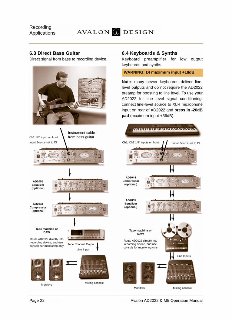
6.3 Direct Bass GuitarDirect signal from bass to recording device.
6.4 Keyboards & SynthsKeyboard preamplifier for low outputkeyboards and synths.
Note: many newer keyboards deliver line-level outputs and do not require the AD2022preamp for boosting to line level. To use yourAD2022 for line level signal conditioning,connect line-level source to XLR microphoneinput on rear of AD2022 and press in -20dBpad (maximum input +36dB).
Page 22 Avalon AD2022 & M5 Operation Manual
RecordingApplications AVALON DESIGN
Input Source set to DI
Monitors
Tape machine or DAW
Route AD2022 directly into recording device, and use console for monitoring only
Mixing console
Line Input
Ch1 1/4” input on front
Instrument cablefrom bass guitar
Monitors Mixing console
Tape machine or DAW
Route AD2022 directly into recording device, and use console for monitoring only
Input Source set to DICh1, Ch2 1/4” inputs on front
AD2044 Compressor
(optional)
AD2055 Equalizer (optional)
Tape Channel Output
AD2044 Compressor
(optional)
AD2055 Equalizer (optional)
Line Inputs
WARNING: DI maximum input +18dB.

7.0 FAQs
The following are answers to FrequentlyAsked Questions about the AD2022 & M5:
Q: Is the AD2022 (M5) durable enough forthe road?A: Yes. the AD2022 (M5) and all Avalonequipment is literally “built like a tank.” Steelchassis, 1/4” thick metal faceplate, metalknobs, all circuit boards are mounted tochassis with stainless steel hardware.
Q: Will the AD2022 (M5) continue to workwhen I travel to different countries?A: Yes. The B2T power supply for the AD2022(M5) has selectable voltages: 100V, 120V,220V, and 240V. It is easy to change thevoltage. See chapter 3.3 (page 8).
Q: Will the AD2022 (M5) work with myunbalanced inputs on my recordingdevice?A: Yes. The AD2022 features both balancedand unbalanced outputs. Make sure that yourcables are wired the same (pin 2 hot). You canuse a cable with an XLR on one end and anRCA or 1/4” on the other. This will work fine forthe unbalanced system, as long as the cablesare not more than 20 ft (6 meters) in length.The M5 output is unbalanced only and workswell with both balanced and unbalanced inputdevices.
Q: Will the AD2022 (M5) work with arecording device designed for -10dBoperation?A: Yes. However the signal coming from theAD2022 (M5) may be too hot. You may needto press the -20dB pad so the signal moreclosely matches the -10dB machine. If youhave a choice, always run at +4dB.
Q: What kind of microphones work bestwith the AD2022 (M5)?A: The AD2022 (M5) was designed to workwith all types of microphones. (ie. condensers,dynamics, ribbons, etc.) It works great withFET condensers as well as tube condensers.Microphone choice and selection is a matter oftaste.
Q: Can I use the AD2022 (M5) live as amicrophone preamp and as a DI box?A: Yes. Many touring artists are currently usingthe AD2022 (M5) as the primary vocal micpreamp as well as a preamp for bass andguitars.
Q: Will the AD2022 (M5) “enhance” thesignal going to a digital recorder?A: Yes. The AD2022 (M5) will give the signal arich and deep sound. The low frequencies willbe more extended and your recording willsound bigger. It will bring your digitalrecordings to life!
Q: What are the main differences betweenthe microphone preamplifiers in theVt-737sp and the AD2022 (M5)?A: The Vt-737sp is a vacuum tube preamp(uses four dual triode tubes) and includes anopto-compressor and equalizer. The AD2022(dual channel) and M5 (mono), are Avalon’s“top of the line” ultra-high performance solidstate microphone preamps. The AD2022 (M5)preamp features 100% discrete electronicsand no tubes. All Avalon Design preamps runin Class A mode and have enormousheadroom and wonderful musicality. Sonically,the Vt-737sp has a more “close-up” soundwhereas the AD2022 (M5) has a larger andmore extended sound stage giving a deeperand more detailed three dimensional image(you hear more of “the room”).
Page 23Avalon AD2022 & M5 Operation Manual
FAQsAVALON DESIGN

Page 24 Avalon AD2022 & M5 Operation Manual
Trouble Shooting AVALON DESIGN
8.0 Trouble Shooting
If you experience any problems with yourAD2022 (M5) always make sure you isolatethe cause to your preamp. In many casesa bad cable or another piece of equipmentin the signal path can produce less thanexcellent results.
To isolate the problem, remove as manypieces of extraneous gear in the signal pathas possible. If you believe that your AD2022(M5) has a problem, set up the following testsystem:
1. Plug your input source (microphone orinstrument) into the AD2022 (M5).
2. Connect the output of the AD2022 (M5)directly to your powered speakers or monitorsystem. Use the INPUT gain control to adjust thevolume.
If you have isolated the problem to theAD2022 (M5) please check the table below forsuggested solutions.
Other problems
If you have any technical questions or areexperiencing problems not listed in our TroubleShooting Table, please call your nearest dealeror the Avalon factory at 949-492-2000 or fax to949-492-4284. You can also email Avalon [email protected].
Problem
No Power
No Power
Lights dim / no sound
No sound
No sound
No sound
Hum or buzzingnoise
Distorted sound
Distorted sound
Overloadingrecording device
Cause
Power cable on B2T not securelyattached into connector
Fuse blown due to power surge orimproper AC voltage setting
Improper AC voltage setting
Incorrect input selector position
Bad cable or connectors
+48v not selected for a microphonethat requires phantom power
bad cables, ground loop or wiremissing from connector link
Microphone or input source overloading
AD2022 (M5) may be overheating
Recording device is -10dB device,AD2022 (M5) is +4dB device
Solution
Check PC-1 power cable, AC sourceand IEC power cable
Replace fuse and check AC voltagesetting on B2T power supply (p. 8)
Check AC voltage setting on B2Tpower supply (p. 8)
Make sure input source selectorswitch is set to the correct position (DI for HI-Z input) (M5 check Hi-Z)
Check cables on input and output
Turn on +48V to supply microphonewith phantom power
check all cables and grounding. Isolatechassis of preamp from equipment rack.
Change microphone or input source;lower input gain, press -20dB pad
Make sure AD2022 (M5) has goodventilation (p. 10)
Press in -20dB pad to attenuate to ausable level.
ALWAYS CHECK YOUR CABLES FIRST!

9.0 Service and Contact Information
Your AD2022 (M5) is built to withstand manyyears of high performance music making. Ifyou experience any malfunctions orproblems, please contact the dealer whereyour unit was purchased. If your AD2022(M5) has outlasted your dealer, pleasecontact Avalon directly.
External CleaningThe AD2022 (M5) can be cleaned using amild cleaner such as 409 or Windex. Do notuse abrasive cleaners or petroleum-basedsolvents.
Contact InformationAvalon DesignPO Box 5976San Clemente, CA 92673United States of America
Tel: 949-492-2000Fax: 949-492-4284
Email: [email protected]: www.avalondesign.com
Page 25Avalon AD2022 & M5 Operation Manual
Service InformationAVALON DESIGN
Problem
Drop in level / Low ouput
No bass or LowFrequencies
Hiss or HF noise
Clip LED Red, VU small movement
Cause
Pin 2 or 3 not connected on XLR miccable
Pin 2 or 3 not connected on XLR miccable
Bad cable, dirty XLR connector pinsbad microphone
High content of peak transients andlow average signal level
Solution
Check / change XLR mic cables
Check / change XLR mic cables
Check / change XLR mic cablesCheck / change microphone
Make sure device following AD2022(M5) can handle the high output
Trouble Shooting Continued

10.0 AD2022 Technical Information
Specifications
Circuit topology: Twin Cascode FET andbipolar low level signal amplifiers, high-voltage, 100% discrete, symmetrical PureClass A
Input type and load: Transformer balancedlow-ratio, 50, 150, 600 and 1k5 ohm inputload selection
Maximum mic level: +36dB balanced XLRpin 2 hot (with -20dB passive attenuator)
Maximum instrument level: +18dB at 100kohms instrument input level, standard mono1/4 inch jack.
Input attenuator: -20dB resistive pre-transformer primary, sealed silver relay
Phantom power: +48v regulated 50mAcapability, sealed silver relay
High pass filter: Passive, variable from 30Hzto 185Hz @ 6dB per octave, sealed silverrelay by-pass
Polarity reverse: sealed silver relay onmicrophone input only
Gain range input: +20dB to +64dB in 4dBsteps
Gain range output: +/-3dB variableconductive plastic potentiometer
Maximum output level: +36dB balanced 600ohms, (+30dB unbalanced) DC coupled,discrete symmetrical Pure Class A
Output type: XLR connector, pin 2 hot
Noise EIN unweighted: -126dB 150 ohm
Noise 20-20kHz unweighted: -102dBu
Distortion (THD, IMD) @ 1kHz: 0.05%
Frequency Response -3dB: 1 to 120kHz
Bandwidth (-3dB): DC to 1MHz
Output meter: Illuminated analog VU meter0dB=+4dBu (balanced output)
Peak meter: Bi-color LED’s 0dB and +20dBpeak detection circuit
AC power supply B2T: External toroidal100v to 240v, 50-60Hz selectable, 85 wattsmaximum. Internal DC regulation on AD2022.
Cables: 1 x 8 ft 4-pin AC cable (PC-1), 1 x 8 ft AC standard IEC cable included
AD2022 Dimensions: 19 x 12 x 3.5 inches 482 x 305 x 89 mm
AD2022 Weight: 15 lbs (6.8kg)
B2T Dimensions: 5 x 7 x 3.25 in127 x 177 x 83mm
B2T Weight: 7lbs (3.2kg)
Dimensions - shipping carton: 24 x 21.5 x 7.5 inches610 x 546 x 190 mm
Weight packed: 25 lbs. ( 11.4 kg)
Page 26 Avalon AD2022 & M5 Operation Manual
Technical Information AVALON DESIGN

Page 27Avalon AD2022 & M5 Operation Manual
Technical InformationAVALON DESIGN
PREA
MPL
IFIE
R
Pure
Cla
ss A
AD 202
2 +
dB
-dB
+
INP
UT
2218
6258
3446
5030
5426
4238
OU
TP
UT
33
1.5
1.5
22
2.5
2.5
11
DC
INP
UT
SO
UR
CE
2
-20d
B+4
8V
150
50D
IM
IC60
0
SIG
NA
L
CH
AN
NE
L T
WO
PU
RE
CL
AS
S A
PR
EA
MP
LIF
IER
AV
AL
ON
0
2H
zF
ILT
ER
PO
LA
RIT
YF
ILT
ER
8050
3514
0
4012
0
100
3018
0
PREA
MPL
IFIE
R
Pure
Cla
ss A
AD 202
2 +
dB
-dB
+
INP
UT
2218
6258
3446
5030
5426
4238
OU
TP
UT
33
1.5
1.5
22
2.5
2.5
11
DC
INP
UT
SO
UR
CE
1
-20d
B+4
8V
150
50D
IM
IC60
0
SIG
NA
L
CH
AN
NE
L O
NE
PU
RE
CL
AS
S A
PR
EA
MP
LIF
IER
AV
AL
ON
2010
75
3
32
10
12
de
cib
els
VU
-+
2010
75
3
32
10
12
de
cib
els
VU
-+
0
1AV
AL
ON
AD
20
22
PR
EA
MP
LIF
IER
RE
CA
LL
SH
EE
T
Pu
re C
lass A
MIC
RO
PH
ON
E P
RE
AM
PL
IFIE
R
AD
20
22
Ava
lon
Des
ign
is a
div
isio
n of
Ava
lon
Indu
strie
s, In
c.
20
01 c
Hz
FIL
TE
R
PO
LA
RIT
YF
ILT
ER
8050
3514
0
4012
0
100
3018
0
10.1 AD2022 Recall Sheet

Page 28 Avalon AD2022 & M5 Operation Manual
Technical Information AVALON DESIGN
2012
DIS
CR
ET
EF
ET
CLA
SS
AA
MP
LIF
IER
2010
DIS
CR
ET
EP
UR
E C
LAS
S A
A
MP
LIF
IER
2010
DIS
CR
ET
EP
UR
E C
LAS
S A
A
MP
LIF
IER
FE
T
B~P
B~P
OU
TPU
T
1 62 3 4 5
0v
40vA
C
TO C
H.2
+36v
-36v
0v2
+20v
1 62 3 4 5
0v
40vA
C
+36v
-36v
0v2
+20v
40v-
0-40
v
DC
RE
GU
LATO
R
RE
LAY
-20d
B P
AD
INP
UT
ON
+36v
PH
AN
TOM
+48v
DI ~
INS
T.IN
PU
T
INP
UT
SE
LEC
TOR
PO
LAR
ITY
RE
VE
RS
E
SE
RV
O
RE
LAY
RE
LAY
TRIM
RE
LAY
RE
LAY
HI-
CU
RR
EN
T
DIS
CR
ETE
LIN
E D
RIV
ER
-20d
B
PA
D
+48v
PO
WE
R
INS
T.
INP
UT
600
OH
M
150
OH
M
50 OH
M
HIP
AS
S
IN
RE
LAY
HI-
Z
DI
50 150
600
MIC
MIC
RO
PH
ON
ETR
AN
SFO
RM
ER
RE
LAY
-3dB
~+3d
B
+18d
B ~
+62
dB
FRE
QU
EN
CY
30~1
85H
z
Pur
e C
lass
A M
icro
phon
e &
Inst
rum
ent P
ream
plifi
er
Ava
lon
Des
ign
is a
div
isio
n of
Ava
lon
Indu
stri
es,
Inc.
20
01 c
Ava
lon
Indu
stri
es,
Inc.
San
Cle
men
te,
Cal
iforn
ia.
U.S
.A.
AV
ALO
N A
D20
22 S
IGN
AL
DIA
GR
AM
UN
BA
LAN
CE
D10
0k O
HM
+18d
B M
AX
BA
LAN
CE
D50
~1k5
OH
M+3
6dB
MA
X
UN
BA
LAN
CE
D60
0 O
HM
+30d
B M
AX
BA
LAN
CE
D60
0 O
HM
+36d
B M
AX
FILT
ER
MIC
~ IN
ST
MIC
RO
PH
ON
EIN
PU
T
LIN
EO
UTP
UT
LIN
EO
UTP
UT
+12v
+12v
-15v
+15v
-36v
+36v
+48v
INP
UT
GA
IN
VU
ME
TER
80v
AC
(B
2T)
1822
2630
34
+ -
3842
4650
5458
62
HI-P
AS
S
FILT
ER
DC
red
+20d
B
SIG
NA
L
gree
n 0d
B+3
6v-3
6v
vu
LED
DR
IVE
R
ME
TER
BU
FFE
R0d
B=+
4dB
u
+20v
VU
LAM
PS
+36v
-36v
+36v
-36v
+20v
0v3
+20v
-15v
+12v
ON
ON
SE
RV
O
1 62 3 4 5
PS
UIN
RE
LAY
+48v
ON
O-/ /
2022
AV
AL
ON
DE
SIG
N
+12v
RE
LAY
S
SE
RV
O
HI-
CU
RR
EN
T
DIS
CR
ETE
LIN
E D
RIV
ER
10.2 AD2022 Block Diagram
11.0 M5 Technical Information
Specifications
Circuit topology: Twin Cascode FET andbipolar low level signal amplifiers, high-voltage, 100% discrete, symmetrical PureClass A
Input type and load: Transformer balancedlow-ratio 1k5 ohm input load selection
Maximum mic level: +36dB balanced XLRpin 2 hot (with -20dB passive attenuator)
Maximum instrument level: +18dB at 100kohms instrument input level, standard mono1/4 inch jack.
Input attenuator: -20dB resistive pre-transformer primary, sealed silver relay
Phantom power: +48v regulated 50mAcapability, sealed silver relay. (BK-1 +130VDPA (B&K) option available.)
High pass filter: Passive, variable from 30Hzto 185Hz @ 6dB per octave, sealed silverrelay by-pass
Polarity reverse: sealed silver relay onmicrophone input
Gain range input: +20dB to +64dB in 4dBsteps
Maximum output level: +30dB unbalanced600 ohms, DC coupled, discrete symmetricalpure Class A
Output type: XLR connector, pin 2 hot(optional balanced JT-1 Jensen transformer)
Noise EIN unweighted: -126dB 150 ohm
Noise 20-20kHz unweighted: -102dBu
Distortion (THD, IMD) @ 1kHz: 0.05%
Frequency Response -3dB: 1 to 120kHz
Bandwidth (-3dB): DC to 1MHz
Output meter: Illuminated analog VU meter0dB=+4dBu
Peak meter: Bi-color LED’s 0dB and +20dBpeak detection circuit
AC power supply B2T: External toroidal100v to 240v, 50-60Hz selectable, 28 wattsmaximum. Internal DC regulation on M5.
Cables: 1 x 8 ft 4-pin AC cable (PC-1), 1 x 8 ft AC standard IEC cable included
M5 Dimensions: 8.5 x 3.5 x 12 inches 216 x 88 x 305 mm
M5 Weight: 15 lbs (6.8kg)
B2T Dimensions: 5 x 7 x 3.25 in127 x 177 x 83mm
B2T Weight: 7lbs (3.2kg)
Dimensions - shipping carton: 24 x 21.5 x 7.5 inches610 x 546 x 190 mm
Weight packed: 25 lbs. ( 11.4 kg)
Page 29Avalon AD2022 & M5 Operation Manual
Technical InformationAVALON DESIGN

Page 30 Avalon AD2022 & M5 Operation Manual
Technical Information AVALON DESIGN
2010
75
3
32
10
12
de
cib
els
VU
-+
1
AV
AL
ON
M5
MO
NO
PR
EA
MP
LIF
IER
RE
CA
LL
SH
EE
T
Pu
re C
lass A
MIC
RO
PH
ON
E P
RE
AM
PL
IFIE
R
M5
Ava
lon
Des
ign
is a
div
isio
n of
Ava
lon
Indu
strie
s, In
c.
20
01 c
AV
AL
ON
DE
SIG
N
FIL
TE
R
5095
100
130
40 35
2018
5
8570
HI-
Z
INP
UT
AV
AL
ON
M5
PU
RE
CL
AS
S A
- H
IGH
VO
LT
AG
E -
PR
EA
MP
LIF
IER
PA
DO
UT
PU
T L
EV
EL
-20d
B
PO
LA
RIT
Y
INP
UT
SIG
NA
LP
OW
ER
FIL
TE
R
+dB
MIC
RO
PH
ON
E
2258
3446
5030
5426
4238
2010
75
3
32
10
12
de
cib
els
VU
-+
2A
VA
LO
N
DE
SIG
N
FIL
TE
R
5095
100
130
40 35
2018
5
8570
HI-
Z
INP
UT
AV
AL
ON
M5
PU
RE
CL
AS
S A
- H
IGH
VO
LT
AG
E -
PR
EA
MP
LIF
IER
PA
DO
UT
PU
T L
EV
EL
-20d
B
PO
LA
RIT
Y
INP
UT
SIG
NA
LP
OW
ER
FIL
TE
R
+dB
MIC
RO
PH
ON
E
2258
3446
5030
5426
4238
Hz
Hz
11.1 M5 Recall Sheet

Page 31Avalon AD2022 & M5 Operation Manual
Technical InformationAVALON DESIGN
+24v
2012
DIS
CR
ET
EF
ET
CLA
SS
AA
MP
LIF
IER
2010
DIS
CR
ET
EP
UR
E C
LAS
S A
A
MP
LIF
IER
FE
T
B~P
80v
AC
(B2T
)
40v-
0-40
v
DC
RE
GU
LATO
R
RE
LAY
-20d
B P
AD
INP
UT
ON
+36v
PH
AN
TOM
DI ~
INS
T.IN
PU
T
PO
LAR
ITY
RE
VE
RS
E
SE
RV
O
RE
LAY
HI-
CU
RR
EN
T
DIS
CR
ETE
LIN
E D
RIV
ER
-20d
B
PA
D
+48v
PO
WE
R
HIP
AS
S
IN
RE
LAY
HI-
Z
MIC
RO
PH
ON
ETR
AN
SFO
RM
ER
RE
LAY
6dB
/oct
+18d
B ~
+62
dB
FRE
QU
EN
CY
30~1
85H
z
Pur
e C
lass
A M
icro
phon
e &
Inst
rum
ent P
ream
plifi
er
Ava
lon
Des
ign
is a
div
isio
n of
Ava
lon
Indu
stri
es,
Inc.
20
01 c
Ava
lon
Indu
stri
es,
Inc.
San
Cle
men
te,
Cal
iforn
ia.
U.S
.A.
AV
ALO
N M
5 S
IGN
AL
DIA
GR
AM
UN
BA
LAN
CE
D10
0k O
HM
+18d
B M
AX
BA
LAN
CE
D50
~1k5
OH
M+3
6dB
MA
X
600
OH
M+3
0dB
MA
X
FILT
ER
HI-
Z
MIC
BP
A
RE
LAY
MIC
RO
PH
ON
EIN
PU
T
LIN
EO
UTP
UT
+12v
-15v
+15v
-36v
+36v
+48v
INP
UT
GA
IN
VU
ME
TER
+ -
HI-P
AS
S
FILT
ER
DC
red
+20d
B
SIG
NA
L
gree
n 0d
B
vu
LED
DR
IVE
R
ME
TER
BU
FFE
R0d
B=+
4dB
u
+36v
-36v
+36v
-36v
-36v
HV
0v3
12v
LAM
PS
+24v
-15v
+12v
+12v
HV
0v
ON
ON
SE
RV
O
DC
RE
G
DC
RE
G
RE
LAY
+48v
OFF
130v
48v
+12v
O-/ /
2022
AV
AL
ON
DE
SIG
N
ON
+12v
RE
LAY
S
HI-Z
INP
UT
JT-1
OP
TIO
N
BK
-1 O
PTI
ON
JEN
SE
N O
UTP
UT
TR
AN
SF
OR
ME
R
BP
A M
IC13
0v H
VP
OW
ER
BP
A M
ICIN
PU
T
11.2 M5 Block Diagram

12.0 Warranty
Avalon Industries, Inc. warrants this productagainst defects in material or workmanship asfollows:1. For a period of one (1) year from the dateof purchase Avalon will pay the labor chargesto repair the defective product. After this one(1) year period, all labor charges will be paidby the customer.2. Avalon will supply at no charge, new orrebuilt replacements for any defectivemechanical switches, potentiometers ormoving parts for a period of one (1) year fromoriginal date of purchase.3. This warranty is void if the product hasbeen found to be subjected to misuse, abuseor unauthorized service.4. This warranty does not cover cosmeticdamage, and damage due to acts of God,accident or transit damage.5. Proof of purchase in the form of a bill ofsale or invoice to provide evidence that theunit is within the warranty period must bepresented to obtain warranty service.6. This warranty is only valid if the serialnumber appears on the product.
Outside of the USA
Please check www.avalondesign.com foryour nearest authorized service center.
12.1 Returns
If your AD2022 (M5) has become defectivewithin the one (1) year period as specifiedabove, please contact the place of purchase toarrange for warranty repair. If you would ratherwork directly with Avalon, please call the factoryat 949-492-2000, send a fax to 949-492-4284or email at [email protected].
13.0 Safety Standards
Avalon Industries, Inc. declares that theAD2022 (M5) conforms to standardsEN55013 (Emissions), EN55020 (Immunity),and EN60065 (Product Safety).
Page 32 Avalon AD2022 & M5 Operation Manual
Warranty and Safety Standards AVALON DESIGN
To return a unit to Avalon for repair orexchange, you will need to obtain a ReturnAuthorization Number (RA) from Avalon. Donot send your unit to Avalon without anRA number.

Appendix A - Glossary
amplification – The process by which asignal level is increased.
amplitude – The distance above or below thecenterline of a signal’s waveform. The greaterthe distance from the centerline, the largerthe pressure variation or electrical signal.
attack – The initial transient or first part of theenvelope of a signal. The beginning of a note.
attenuate – To reduce the signal level.
balanced – In a classic balanced audiocircuit, the two legs of the circuit (+ and -) areisolated from the circuit ground by exactly thesame impedance. Additionally, each legcarries the signal at exactly the same levelbut with opposite polarity. Balanced inputcircuits can offer excellent rejection of noiseand grounding loops.
balanced line – A cable having twoconductors and a ground connection andoften surrounded by a shield. With respect toground, the conductors are at equal potentialbut opposite polarity. These lines are oftenused in professional setting to reduce oreliminate induced noise and interference fromexternal electromagnetic sources.
bandwidth – The band of frequencies thatpass through a device with a loss of less than3dB, expressed in hertz or in musicaloctaves.
capacitance – Capacitance is the ability ofan object to store an electrical charge.
channel – A single functional path in an audiocircuit.
clipping – A cause of audio distortion that isthe result of excessive gain requiring thepeaks of the audio signal to rise above thecapabilities of the circuit.
compressor – In effect, an automatic fader.When the input signal exceeds apredetermined level (called the threshold),the gain is reduced by the compressor andthe signal is attenuated.
compression ratio – The ratio of signaldynamic range between the compressor inputand the output above the device’s setthreshold point (such as 2:1, 4:1, 20:1).
console – A term for a sound mixer, usually alarge desk-type mixing board used to mixtogether multiple track musical material.
crosstalk – The unwanted leakage of asignal from one channel or track onto another.
decibel (dB) – A unit of audio measurementof sound pressure level (SPL), signal level,and changes of difference in signal level. Thedecibel is a logarithmic (log) mathematicalfunction that reduces large numeric valuesinto smaller, more manageable numbers.Decibel is calculated as 10 times the log ofthe ratio of two powers, and 20 times the logof the ratio of two voltages.
dBm: Decibels referenced to 1 milliwatt.
dBu or dBv: Decibels referenced to 0.775volt.
dBV: Decibels referenced to 1 volt.
Page 33Avalon AD2022 & M5 Operation Manual
GlossaryAVALON DESIGN

de-ess – Using a frequency-dependentfunction in a compressor to reduce excessivesibilance ("sss”, "sh," and "ch") sounds.
detent – A point of slight physical resistance(a click stop) in the travel of a knob or slidecontrol.
dynamic range – The range between themaximum and minimum sound levels of anaudio system. It is usually expressed indecibels as the difference between the levelat peak clipping and the level of the noisefloor.
equalizer – A frequency-dependent amplifierthat controls the relative amplitude of variousfrequencies in the audible bandwidth. Theequalizer lets you exercise tonal control overthe harmonic content or timbre of a sound.
EQ curve – A graph of the response of anequalizer, with frequency on the x (horizontal)axis and amplitude (level) on the y (vertical)axis. Equalizer types and effects are oftennamed after the shape of the graphedresponse curve, such as peak, dip, shelf,notch, knee and so on.
fade – A slow change in volume.
fader – A linear attenuation device or linearvolume control.
feedback – The returning of a loudspeakersignal back into a microphone feeding theloudspeaker. Excessive feedback results inunpleasant, screaming sounds usually atparticular high frequencies.
filter – A simple equalizer designed toremove certain ranges of frequencies. A high-pass filter (also called a low-cut filter) reducesor eliminates frequencies below the cutofffrequency. There are also high-cut (low-pass)filters, bandpass filters, which cut both highand low frequencies but leave a band offrequencies in the middle untouched, andnotch filters, which remove a narrow band butleave the high and low frequencies alone.
flanging – A process whereby a delayedsignal is combined with itself undelayed. Thedelay is varied to create continual changes insound.
frequency – The rate at which a sound waverepeats a cycle. The number of cycles thatoccurs over the period of one second is calledhertz (Hz). Often , the perceived range ofhearing is from 20Hz to 18,000Hz.
gain – The measure of how much a circuitamplifies a signal. Gain may be stated as aratio of input to output values, such asdecibels from line amplifier.
gain riding – Adjusting the preamp gainwhile recording.
gain stage – An amplification point in a signalpath, either within a system or a singledevice. Overall system gain is distributedbetween the various gain stages.
graphic EQ – A type of equalizer where thefrequency bands for cut/boost andbandwidths are fixed. Graphic EQs areusually controlled by faders instead of knobs.
ground – The point of zero voltage in a circuitor electrical system.
Page 34 Avalon AD2022 & M5 Operation Manual
Glossary AVALON DESIGN

Page 35Avalon AD2022 & M5 Operation Manual
GlossaryAVALON DESIGN
ground loop – Exists in an impropergrounding situation, whereby a DC currentdifferential exists between one signal path andanother, resulting in a 50Hz or 60Hz hum.
headroom – The difference between nominaloperating level and peak clipping in an audiosystem.
hertz – The unit of measure for frequency ofoscillation, equal to 1 cycle per second.Abbreviated Hz. kHz is an abbreviation forkilohertz, or 1000 Hertz.
impedance – The opposition of current flowin a circuit.
knee – A sharp bend in an EQ responsecurve. Also used in describing dynamicprocessors.
LED – Acronym for light emitting diode.
line level – A signal level that is referenced toeither +4dB (professional) of –10dB (semi-pro/consumer).
mastering – The processing and transfer of afinal, sequenced or mixed audio tape to amedium for duplication.
mixdown – The process in which theseparate audio tracks of a multiple trackrecording are combined, balanced, androuted through the recording console. Duringmixdown, volume, tone, special effects andspatial positioning can be artistically set bythe engineer to create a stereo or surroundsound mix that is then recorded to a masterrecording device, such as a DAT recorder.
monaural – Confined to a single channel.One microphone is a mono pickup; manymicrophones mixed to one channel is a monomix. Several mono sources, however, can bepanned into a stereo (or two-channel) mix.
mono – short for monaural.
noise – Unwanted sounds. Hum, buzz orhiss; could be crosstalk or digital hiss.
noise floor – The residual level of noise inany system. The lower the noise floor and thehigher the headroom, the more usabledynamic range a system has.
overload – The distortion that occurs whenan applied signal exceeds a system’smaximum input level.
pad – A switch circuit that attenuates the levelby a specified amount (such as -20dB).
parametric EQ – A parametric EQ allowscontinuous control of each of the threeprimary EQ parameters (frequency, gain andbandwidth) independently.
passive EQ - A filter topology similar to earlyequalizer designs (such as pultec) wherepassive components (capacitors) are only usedto filter the signal. In a passive EQ, amplifiers areonly used as make-up gain devices. Thecapacitors used to filter the signal are notincorporated in the active feedback stage of thecircuit. Passive EQ’s have a distinctively smoothand musical sound.
peak amplitude – The maximum instantaneousamplitude of a signal.

peak LED – A light that flashes when amaximum signal level is reached.
phantom power – Polarizing supply voltagefor condenser microphones supplied directlythrough the microphone cable (usually +48V).
phase – The degree of progression in thecycle of a wave, where one complete cycle is360 degrees. Phase is measured in degreesof a cycle and will result in audible variationsof a combined signal’s amplitude and overallfrequency response.
phase shift – The difference in degrees ofphase angle between corresponding pointson two waves.
polarity – See phase.
potentiometer (pot) – A rotary gain, pan, orother type of continuously variable signalcontrol.
preamplifier - A piece of equipment thatboosts the signal level so that the signaloperates at a higher and more desired levelenabling greater frequency and dynamicrange.
PSU - Power supply unit
release time – Once compression has begun,the time taken for the attenuated signal to returnto 63% of its original (unprocessed) level.
resistance – The opposition to the flow ofDC current in a wire or circuit.
ribbon microphone – A microphone thatuses a diaphragm of extremely thin,aluminum ribbon suspended in a strong field
of magnetic flux. As sound-pressurevariations displace the metal diaphragm inaccordance with air-particle velocity, theribbon cuts across the magnetic lines of flux.This induces a current in the ribbon ofproportional amplitude and frequency to theacoustic waveform.
shelving filter – A rise or drop in frequencyresponse at a selected frequency that tapersoff to a preset level and continues at the levelto the end of the audio spectrum.
side chain - A function on a compressorwhere a specified frequency range iscompressed more than the overall musicalprogram. Many compressors have a jack foran equalizer to be inserted into thecompressor drive electronics.
signal LED - Light flashed when signal of aspecified level occurs. On AD2022 (M5)green light flashes at 0dB, then flashes red at+20dB.
spectral control - The use of a side chain ina compressor to compress selectedfrequencies of a musical program. Oneexample of spectral control is removing the“sss” sounds of a vocal (de-essing).
sweep EQ – An equalizer that allows you to"sweep" or continuously vary the frequency ofone or more sections.
unbalanced – An electrical circuit in whichthe two legs of the circuit are not balancedwith respect to ground. Unbalanced circuitconnections require only two conductors(signal "hot" and ground). Unbalanced audiocircuitry is less expensive to build, but undercertain circumstances is more susceptible to
Page 36 Avalon AD2022 & M5 Operation Manual
Glossary AVALON DESIGN
noise. An unbalanced audio cable has onlyone conductor plus a surrounding shield, inwhich the shield is at ground potential. Theconductor and the shield carry the signal.
VU meter - Volume unit meter. A meter thatreads audio voltage levels in or out of a pieceof equipment and is designed to match theear's response to sudden changes in level.
volume – Electrical or sound level in an audiosystem.
waveform – A graph of a signal’s soundpressure or voltage level versus time.
Page 37Avalon AD2022 & M5 Operation Manual
GlossaryAVALON DESIGN