adaptive modulation and superposition coding for mimo data
TRANSCRIPT
Adaptive Modulation and Superposition Coding for MIMO
Data Transmission Using Unequal Error Protection and
Ordered Successive Interference Cancellation Techniques
Wasan Kadhim Saad1, Waheb A. Jabbar
2, and Bashar J. Hamza
1
1Al-Furat Al-Awsat Technical University, Engineering Technical College-Najaf, 31001 Najaf, Iraq
2Faculty of Engineering Technology, Universiti Malaysia Pahang (UMP), Lebuhraya Tun Razak, 26300, Gambang,
Kuantan, Pahang, Malaysia
Email: [email protected], [email protected], [email protected]
Abstract—This paper proposes and discusses an efficient
multiple input multiple output (MIMO) system for adaptive
modulation coding (AMC) based on unequal error protection
(UEP) and superposition coding (SPC) by exploiting the
features of sub channel partitioning. Using AMC, an appropriate
order of modulation and code rate to suit the channel state
information (CSI) can be selected. The realization of UEP is
achieved through adaptive allocation and transmission of high
and low-priority data signals over high and low quality sub
channels respectively. A multistage decoding (MSD) receiver
with the ordered successive interference cancellation (OSIC)
technique is employed in the receiver by using two linear
receiver signal combiner (RSC) techniques: zero-forcing (ZF)
and minimum mean square error (MMSE). The data priority can
be distinguished by the signal-to-noise ratio (SNR) and can be
categorized as mode-B and mode-G. The simulation results
show that the SNR performance enhancement for the UEP-
MIMO scheme is approximately 9.4 dB compared to the others
schemes. In addition, for the UEP-MIMO scheme, the overall
data system transmission from mode-B outperforms that of
mode-G with SNR gains of 8.2 dB compared to the 7.5 dB for
the UEP-SISO scheme. Also, MMSE-SPC also outperforms the
ZF-SPC with a 3 dB SNR at a bit error rate (BER) of 10-3. Index Terms—Adaptive modulation and coding (AMC),
multiple-input multiple-output (MIMO) channel, superposition
coding (SPC), unequal error protection (UEP), spatial
multiplexing (SM), zero-forcing (ZF) and minimum mean
square error (MMSE).
I. INTRODUCTION
Providing high-quality video- and multimedia oriented
services is regarded as a task of great importance for
enhancing the next generation of wireless broadband
communication systems. However, effective video data
transmissions are highly sensitive to errors over time-
varying wireless channels, which has become the major
challenge. The data priority (high-priority (HI) and low-
priority (LI) subchannels) can be categorized as mode-B
(HI only) and mode-G (HI and LI). Thus, it is important
to investigate what actually occurs when making a video
call, for example, in real-time video conferencing, to
Manuscript received November 28, 2018; revised July 3, 2019. Corresponding author email: [email protected].
doi:10.12720/jcm.14.8.696-705
obtain a thorough and general understanding of this
phenomenon. In this process, the user’s face, which is
taken in the foreground, is part of the high-importance
(HI) data layer, whereas the background scene reflects the
low-importance (LI) data layer “Ref. [1], [2]”. There is a
priority to transmit more reliable HI data than LI data,
which is one requirement for optimising the quality of
service (QoS). Hence, it is more important to protect the
HI data than the LI data from being corrupted by the
channel. In the last decade, there have been an increasing
number of emergent plans or schemes devoted to develop
error control schemes in the field of wireless
communication. One of these schemes is known as UEP,
where the original and initial proposal of this scheme was
for single-carrier systems, but there is a potential
extension of its use for multi-carrier systems “Ref. [2]”.
UEP has the ability to divide the data signal into two or
more layers based on priorities. For instance, the HI layer
carries more of the data signal and can perform self-
decoding to reconstruct the original signal. However, the
LI layer carries the data of less importance, which are
employed to enhance the signal quality. Because errors in
the HI layer have adverse impacts on the quality of the
reconstructed signal, it is important to reduce the errors as
much as possible. In contrast, errors in the LI layer can be
tolerated more. Therefore, the goal of UEP is to protect
the HI layer as much as possible to achieve a high-quality
signal “Ref. [2], [3]”. The effectiveness of UEP as a
method is related to video transmission in error-prone
wireless environments. Its effectiveness is attributed to its
ability to protect various parts of the video data with
various levels of importance. In its basic function, UEP is
capable of making changes in the distribution of errors
without consuming additional resources. Thus, the more
important data suffers from fewer bit errors “Ref. [4]-[6]”.
In contrast, AMC is a well-known technique that has
gained wide consideration and investigation in the recent
literature on wireless communication systems. It is also
recognised as an effective link adaptation technique,
which has been widely applied in wireless
communication systems for the last few years “Ref. [7],
[8]”. The AMC technique permits the systems to select
the most suitable modulation and coding scheme (MCS)
Journal of Communications Vol. 14, No. 8, August 2019
696©2019 Journal of Communications

that best fits the instantaneous channel quality, therefore
selecting the MCS with a higher modulating order and
coding rate to maximise the transmission data rate, and
vice versa for low-quality channels. Thus, different MCSs
will be utilised for different channel conditions, so that,
an optimal performance in terms of both bit error rate
(BER) and data rate can be achieved “Ref. [9]”.
However, SPC modulation is considered as an
alternative method to the other coded modulation
techniques with bandwidth efficiency. In SPC modulation,
the linear superimposition is made for the number of
encoded layers before the transmission “Ref. [10], [11]”.
In the SPC modulation scheme proposed by “Ref. [12]”,
the various bit streams are transferred on the same
modulation periods. The authors in “Ref. [13]” proposed
a SPC modulation scheme that utilises block codes as its
component code, which is known as superposition block
coded modulation. These researchers reported a
significant gain from low encoding and decoding
complexity with the proposed scheme.
This paper proposed an effective AMC technique,
which employs UEP-SPC scheme for transmitting the
data through the wireless fading MIMO channel. The
proposed system in this paper aims to provide a reliable
quality of reception for even the lowest-quality channels
through the exploitation of the layered data and
instantaneous CSI. However, the proposed scheme is
capable of delivering diverse data signal layers over
MIMO wireless channels along with different protection
levels in an adaptive manner that depends on the SNR of
the reception. The results obtained from the simulation
revealed that the proposed system has efficiently and
significantly improved in the execution of the wireless
data transmission systems through MIMO channel
compared to the single-input single-output (SISO) and
Single-Input Multiple-Output (SIMO) systems.
Furthermore, the study showed that flexible trade-offs in
terms of execution improvement between the HI and LI
data layers in additional to the overall (HI + LI) data
system can be achieved by making adjustments to the
modulation power fractions of the layers. Finally, a lower
BER can be obtained when the superimposed signal
transmission has a uniform constellation.
In addition, Spatial Multiplexing (SM) is the one type
of the MIMO techniques that used to significantly
increase the data rates (enabling high spectral efficiencies)
or channel capacity. SM is achieved by transferring
various data streams on the same time-frequency grid
“Ref. [14]-[16]”. However, in SM-MIMO technique, the
data stream is subdivided into independent sub streams,
one for each transmitting antenna. Therefore, in a SM
configuration, which that focuses on the current study,
the system is capable of obtaining substantial gains in the
data rate, and such a scheme can be use with or without
the transmission of channel knowledge “Ref. [17]”. The
standard linear RSC detection methods that are used on
the receiver side include the ZF and MMSE techniques.
However, both of ZF and MMSE are considered in the
simulation work.
The rest of the paper is organised as follows: The
proposed UEP-AMC-SPC-MIMO system is discussed in
section 2, where the system design for two modes of
operation, mode-G and mode-B, is highlighted. Section 3
presents and discusses the performance evaluation of the
proposed system, and section 4 provides the simulation
results and discussion for the proposed system with the
OSIC. Finally, section 5 is drawn the concluding remarks
of this paper.
II. PROPOSED UEP-AMC-SPC-MIMO SYSTEM MODEL
“Fig. 1,” illustrates the block diagram of the proposed
transmission system employing UEP, which is based on
sub channel partitioning. For a simple illustration, the
diagram will present only the functional blocks that are
related to data transmission; the blocks that are related to
the feedback are omitted. As observed on the transmitter
side, the source data of the adaptive transmitter stage are
split into several various priority layers based on the
priorities of the data, i.e., the quality of the reception.
Because the proposed scheme has the ability to support
the data at different layers, we implemented a system
with only two data layers for simplicity in the analysis,
namely, (i) the HI data layer, which comprises the more
important data, and (ii) the LI data layer, which
comprises the less important data. In contrast to the LI
data layer, a higher level of protection against
propagation errors will be emphasised in the HI data layer
during the data transmission because these errors have a
significant effect on the quality of the data. Then, each
layer is encoded and modulated separately by utilising
AMC, which is subject to the CSI. Therefore, the CSI-
based AMC is used here to encode and modulate each
data layer individually. In the encoding stage, these two
layers are encoded with an adaptive forward error
correction (FEC) code to produce the HI and LI code
words, HIv and LIv . In the modulation stage, these code
words are modulated with the adaptive modulation (AM)
order, and the level of UEP for each priority layer is used
to protect the layer from error transmission.
The various UEP levels are equipped with the HIv and
LIv code words by assigning various power ratios, HI
and LI , of the overall transmitted power, P. Thus, the
various modulated power ratios are assigned to the
various priority layers, where modulation of a higher-
priority data layer with power ratio is higher than data
layer of a lower-priority. In addition, the power ratio of
each layer is provided in accordance with its priority,
i.e.,LIHI > . Therefore, the total average power ratio
for modulating bit streams is assumed to be one and can
be stated as follows:
Journal of Communications Vol. 14, No. 8, August 2019
697©2019 Journal of Communications

21h
MIMO
channel
Spatial
Multiplexer
V
HIs HIv
Mux
Encoder Modulator
s
1v
Data
Partitioning
2v
ModulatorInput
ControllerLIs
LPvEncoder
F.B of
CSI
1x
2x
1y
2y
11h
22h
12h
Linear
detector
(ZF &
MMSE)
Multistage
Demodulator
(O-SIC)
Multistage
Decoder Combiner
dr s
Fig. 1. Block diagram of the proposed UEP-AMC-SPC-MIMO system model.
1 LIHI
(1)
where 1P
P
P
P LIHI (2)
Therefore, LIHI PPP (3)
where HIP and
LIP are the power utilised in the HI and LI
modulators, respectively. This criterion results in
transmitting the data of the highest-priority layer with the
highest reliability and those of the lowest-priority layer
with the lowest reliability. To construct the transmission
signal, the adaptive modulated signals of two layers are
then superimposed, which can be illustrated as follows:
2
1n
nvV (4)
Therefore, to avoid losing generality and to achieve
transmission of high spectral efficiency, the scheme
proposed in the current study is operated by using two
system modes, namely, mode-G and mode-B, which will
be introduced based on the output of the CSI feedback
signal (CFS). The MCS will be chosen according to the
wireless channel quality or received SNR. Thus,
depending on the CFS, the proposed system switches the
modulation order and coding rate to match with the
immediate channel quality. Therefore, at the receiver, the
SNR is estimated and sent back to the transmitter through
the feedback channel using the CSI signal. Thus, mode-G
and mode-B are selected by the CFS when the CSI signal
displays the SNR of the received signal placed between
the designed SNR thresholds of SNR1 and SNR2, where
12 > SNRSNR . The range of the received SNR is split into
several regions using a set of threshold values. The values
of the SNR thresholds are selected depending on the
BERtarget of the application, which is a real-time video
application in this case. Therefore, depending on the SNR
range that assesses the current SNR, the MCS of the
proposed system is switched to preserve the BER of the
system such that it remains below the target BER.
Therefore, mode-G is selected when 2SNRSNR ,
where it represents a default mode. Alternatively, mode-
G is selected when a good CSI feedback signal is
received, i.e., high-quality channel. During the initial
transmission, the system is assumed to be in mode-G
operation. Thus, the MCS is chosen with a higher
modulation and coding rate. Reliable decoding of both
the HI and LI bit streams is achieved when the operation
of the system is in mode-G. However, mode-B is selected
when 1SNRSNR ; therefore, it is selected to indicate a
low-quality channel or lack of a CSI feedback signal.
Thus, the MCS is chosen for this system with lower-order
modulation techniques, which are highly robust against
error without reducing the data rate for the HI layer.
Reliable decoding of the HI bit stream only is achieved
when the system is operated in mode-B. Then, these two
data layers with two various levels of protection are
superimposed, and the signal, V, is sent to the receiver
with two transmitting antennas over two independent flat
Rayleigh fading sub channels by spatially multiplexed
MIMO (SM-MIMO) systems. Such systems are able to
transmit data at a higher speed than MIMO systems by
using antenna diversity techniques. Thus, spatial de
multiplexing or signal detection at the receiver side is
considered a challenging task for SM-MIMO systems,
particularly when the spatial correlation between the
receiving or transmitting antenna is very high (a
correlation coefficient near unity), which means that
signal detection and equalisation at the receiver are
impossible. Because each of the independent channels or
paths is linked with the corresponding receiving antenna,
the received signal at the m-th antenna, my , is given by
2,12
1
mfornVhym
xmm m (5)
where mxV represents the spatially multiplexed user data
signal that is transmitted from the m- th transmitting
antenna, is the m-th column vector of the channel matrix
H, and n refers to the additive white Gaussian noise
(AWGN) with zero mean and a variance of at the m-th
receiving antenna. At the receiver side, the received
signals, my , are then used by the linear detectors, which
are capable of retrieving the transmitted vector through
MIMO systems. Various techniques can be used to
separate the different symbol streams from one another.
These techniques involve the ZF and MMSE as linear
receivers, which perform the function of detecting the
received signals from multiple antennas and are used to
Journal of Communications Vol. 14, No. 8, August 2019
698©2019 Journal of Communications
construct the dr signal, which is then sent to a multistage
demodulator to separate the code word of each m-th
layer, )(mx , from those of the other layers. Moreover,
MSD receiver with the OSIC technique is used to
reconstruct the two layers of data from the superimposed
received signal. This technique is used to enhance the
performance without significantly increasing the
complexity and separating the layers at the receiver side.
It is defined as a bank of linear receivers, each of which
functions as a detector of one of the parallel data streams.
Thus, the detected signal components are successively
cancelled from the received signal at each stage. More
specifically, the detected signal from the received signal
in each stage is subtracted to use the remaining signal
with the reduced interference in the subsequent detection
stage.
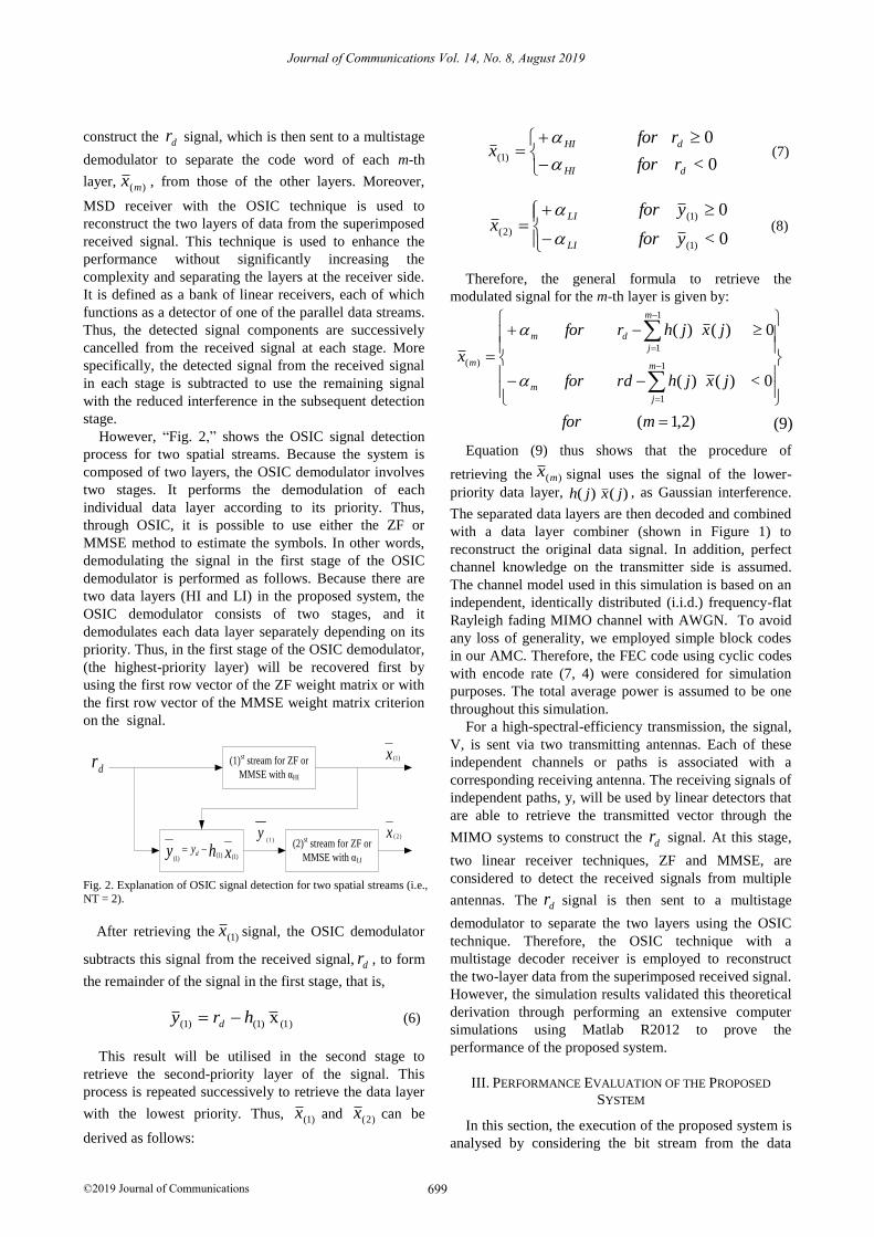
However, “Fig. 2,” shows the OSIC signal detection
process for two spatial streams. Because the system is
composed of two layers, the OSIC demodulator involves
two stages. It performs the demodulation of each
individual data layer according to its priority. Thus,
through OSIC, it is possible to use either the ZF or
MMSE method to estimate the symbols. In other words,
demodulating the signal in the first stage of the OSIC
demodulator is performed as follows. Because there are
two data layers (HI and LI) in the proposed system, the
OSIC demodulator consists of two stages, and it
demodulates each data layer separately depending on its
priority. Thus, in the first stage of the OSIC demodulator,
(the highest-priority layer) will be recovered first by
using the first row vector of the ZF weight matrix or with
the first row vector of the MMSE weight matrix criterion
on the signal.
x )1(
dr (1)st stream for ZF or
MMSE with αHI
(2)st stream for ZF or
MMSE with αLIxhy dy
)1()1()1(
x )2(y)1(
Fig. 2. Explanation of OSIC signal detection for two spatial streams (i.e.,
NT = 2).
After retrieving the )1(x signal, the OSIC demodulator
subtracts this signal from the received signal, dr , to form
the remainder of the signal in the first stage, that is,
x (1))1()1( hry d (6)
This result will be utilised in the second stage to
retrieve the second-priority layer of the signal. This
process is repeated successively to retrieve the data layer
with the lowest priority. Thus, )1(x and )2(x can be
derived as follows:
0<
0)1(
dHI
dHI
rfor
rforx
(7)
0<
0
)1(
)1(
)2(yfor
yforx
LI
LI
(8)
Therefore, the general formula to retrieve the
modulated signal for the m-th layer is given by:
)9()2,1(
0<)()(
0)()(
1
1
1
1
)(
mfor
jxjhrdfor
jxjhrfor
xm
j
m
m
j
dm
m
Equation (9) thus shows that the procedure of
retrieving the )(mx signal uses the signal of the lower-
priority data layer, )()( jxjh , as Gaussian interference.
The separated data layers are then decoded and combined
with a data layer combiner (shown in Figure 1) to
reconstruct the original data signal. In addition, perfect
channel knowledge on the transmitter side is assumed.
The channel model used in this simulation is based on an
independent, identically distributed (i.i.d.) frequency-flat
Rayleigh fading MIMO channel with AWGN. To avoid
any loss of generality, we employed simple block codes
in our AMC. Therefore, the FEC code using cyclic codes
with encode rate (7, 4) were considered for simulation
purposes. The total average power is assumed to be one
throughout this simulation.
For a high-spectral-efficiency transmission, the signal,
V, is sent via two transmitting antennas. Each of these
independent channels or paths is associated with a
corresponding receiving antenna. The receiving signals of
independent paths, y, will be used by linear detectors that
are able to retrieve the transmitted vector through the
MIMO systems to construct the dr signal. At this stage,
two linear receiver techniques, ZF and MMSE, are
considered to detect the received signals from multiple
antennas. The dr signal is then sent to a multistage
demodulator to separate the two layers using the OSIC
technique. Therefore, the OSIC technique with a
multistage decoder receiver is employed to reconstruct
the two-layer data from the superimposed received signal.
However, the simulation results validated this theoretical
derivation through performing an extensive computer
simulations using Matlab R2012 to prove the
performance of the proposed system.
III. PERFORMANCE EVALUATION OF THE PROPOSED
SYSTEM
In this section, the execution of the proposed system is
analysed by considering the bit stream from the data
Journal of Communications Vol. 14, No. 8, August 2019
699©2019 Journal of Communications
source that will be divided into two various data streams
based on their priorities. Thus, the data source is split into
HI and LI bit streams. The encoding and modulation of
both streams are performed with different MCS levels to
obtain a better match with the instantaneous channel
quality to achieve a BER below the target level (BERtarget).
By adjusting the power ratio allocations of the data layers,
the performance of the overall data can be achieved in a
flexible manner. For protection against transmission
errors, the proposed system identifies a UEP level for
each priority layer in the modulation stage. Therefore, the
various UEP levels are submitted by assigning various
modulated power ratios for the various priority layers.
Thus, the higher-priority data layer is modulated with a
higher power ratio and transmitted with higher reliability
and vice versa. As a result of this process, the adaptive
modulated signals are superimposed to produce the signal
that is transmitted in a flat Rayleigh fading MIMO
channel. Therefore, it is important to select these power
ratios carefully on the transmitter side to satisfy the
system design requirements.
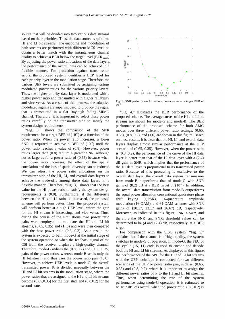
“Fig. 3,” shows the comparison of the SNR
requirement for a target BER of (10-3
) as a function of the
power ratio. When the power ratio increases, a lower
SNR is required to achieve a BER of (10-3
) until the
power ratio reaches a value of (0.8). However, power
ratios larger than (0.8) require a greater SNR, although
not as large as for a power ratio of (0.55) because when
the power ratio increases, the effect of the spatial
correlation and the loss of spatial diversity can be reduced.
We can adjust the power ratio allocations on the
transmitter side of the HI, LI, and overall data layers to
achieve the trade-offs among these data layers in a
flexible manner. Therefore, “Fig. 3,” shows that the best
value for the HI power ratio to satisfy the system design
requirements is (0.8). Furthermore, if the difference
between the HI and LI ratios is increased, the proposed
scheme will perform better. Thus, the proposed system
will perform better at a high UEP level, where the gain
for the HI stream is increasing, and vice versa. Thus,
during the course of the simulations, two power ratio
pairs were employed to modulate the HI and LI bit
streams, (0.65, 0.35) and (1, 0) and were then compared
with the best power ratio (0.8, 0.2). As a result, the
system is expected to bein mode-G at the initial stage of
the system operation or when the feedback signal of the
CSI from the receiver displays a high-quality channel.
Therefore, mode-G utilises the (0.8, 0.2) and (0.65, 0.35)
pairs of the power ratios, whereas mode-B sends only the
HI bit stream and thus uses the power ratio pair (1, 0).
However, to achieve UEP levels in mode-G, the overall
transmitted power, P, is divided unequally between the
HI and LI bit streams in the modulation stage, where the
power ratios that are assigned to the HI and LI bit streams
become (0.65,0.35) for the first state and (0.8,0.2) for the
second state.
0.5 0.55 0.6 0.65 0.7 0.75 0.8 0.85 0.9 0.95 1
18
20
22
24
26
28
30
SN
R (
dB
)
power ratio, qq Fig. 3. SNR performance for various power ratios at a target BER of 10−3
“Fig. 4,” illustrates the BER performance of the
proposed scheme. The average curves of the HI and LI bit
streams are shown for mode-G and mode-B. The BER
performance of the proposed scheme for both AMC
modes over three different power ratio settings, (0.65,
0.35), (0.8, 0.2), and (1,0) are shown in this figure. Based
on these results, it is clear that the HI, LI, and overall data
layers display almost similar performance at the UEP
scenario of (0.65, 0.35). However, when the power ratio
is (0.8, 0.2), the performance of the curve of the HI data
layer is better than that of the LI data layer with a (2.4)
dB gain in SNR, which implies that the performance of
the HI data layer is proportional to its transmitted power
ratio. Because of this processing is exclusive to the
overall data layer, the overall data system transmission
from mode-B outperforms that of mode-G with SNR
gains of (8.2) dB at a BER target of (10-3
). In addition,
the overall data transmission from mode-B outperforms
the equal power allocation conventional quadrature phase
shift keying (QPSK), 16-quadrature amplitude
modulation (16-QAM), and 64-QAM schemes with SNR
gains of (20.17, 23.17 and 26.67) dB, respectively.
Moreover, as indicated in this figure,12 > SNRSNR and
therefore the SNR1 and SNR2 threshold values can be
determined to be (4 and 12.4) dB, respectively, at a BER
target.
For comparison with the SISO system, “Fig. 5,”
explains that if the channel is of high quality, the system
switches to mode-G of operation. In mode-G, the FEC of
the cyclic (15, 11) code is used to encode and decode
both the HI and LI bit streams. As displayed in this figure,
the performance of the SPC for the HI and LI bit streams
with the UEP technique is conducted for two different
scenarios of the UEP or power ratio pair, such as; (0.65,
0.35) and (0.8, 0.2), where it is important to assign the
different power ratios of P to the HI and LI bit streams.
Thus, when determining the rate of the system
performance using mode-G operation, it is estimated to
be 18.7 dB less overall when the power ratio (0.8, 0.2) is
Journal of Communications Vol. 14, No. 8, August 2019
700©2019 Journal of Communications
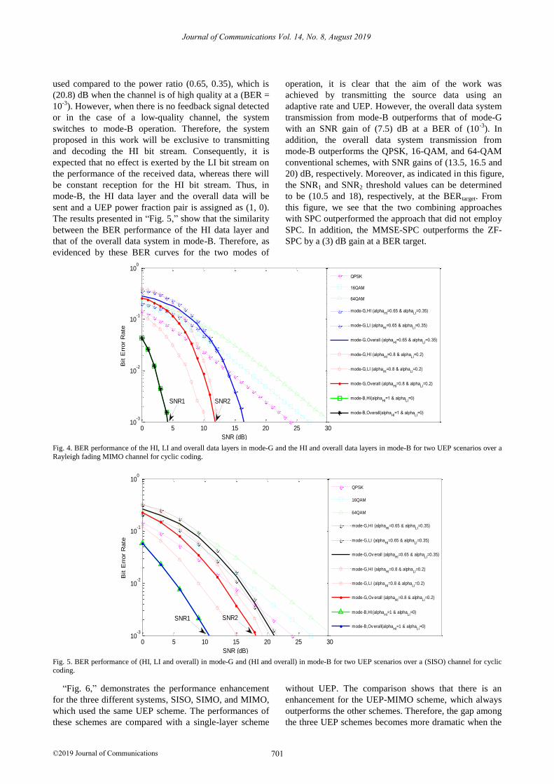
used compared to the power ratio (0.65, 0.35), which is
(20.8) dB when the channel is of high quality at a (BER =
10-3
). However, when there is no feedback signal detected
or in the case of a low-quality channel, the system
switches to mode-B operation. Therefore, the system
proposed in this work will be exclusive to transmitting
and decoding the HI bit stream. Consequently, it is
expected that no effect is exerted by the LI bit stream on
the performance of the received data, whereas there will
be constant reception for the HI bit stream. Thus, in
mode-B, the HI data layer and the overall data will be
sent and a UEP power fraction pair is assigned as (1, 0).
The results presented in “Fig. 5,” show that the similarity
between the BER performance of the HI data layer and
that of the overall data system in mode-B. Therefore, as
evidenced by these BER curves for the two modes of
operation, it is clear that the aim of the work was
achieved by transmitting the source data using an
adaptive rate and UEP. However, the overall data system
transmission from mode-B outperforms that of mode-G
with an SNR gain of (7.5) dB at a BER of (10-3
). In
addition, the overall data system transmission from
mode-B outperforms the QPSK, 16-QAM, and 64-QAM
conventional schemes, with SNR gains of (13.5, 16.5 and
20) dB, respectively. Moreover, as indicated in this figure,
the SNR1 and SNR2 threshold values can be determined
to be (10.5 and 18), respectively, at the BERtarget. From
this figure, we see that the two combining approaches
with SPC outperformed the approach that did not employ
SPC. In addition, the MMSE-SPC outperforms the ZF-
SPC by a (3) dB gain at a BER target.
0 5 10 15 20 25 3010
-3
10-2
10-1
100
SNR (dB)
Bit E
rror
Rate
QPSK
16QAM
64QAM
mode-G,HI (alphaHI
=0.65 & alphaLI
=0.35)
mode-G,LI (alphaHI
=0.65 & alphaLI
=0.35)
mode-G,Overall (alphaHI
=0.65 & alphaLI
=0.35)
mode-G,HI (alphaHI
=0.8 & alphaLI
=0.2)
mode-G,LI (alphaHI
=0.8 & alphaLI
=0.2)
mode-G,Overall (alphaHI
=0.8 & alphaLI
=0.2)
mode-B,HI(alphaHI
=1 & alphaLI
=0)
mode-B,Overall(alphaHI
=1 & alphaLI
=0)
SNR2SNR1
Fig. 4. BER performance of the HI, LI and overall data layers in mode-G and the HI and overall data layers in mode-B for two UEP scenarios over a
Rayleigh fading MIMO channel for cyclic coding.
0 5 10 15 20 25 3010
-3
10-2
10-1
100
SNR (dB)
Bit E
rror
Rate
QPSK
16QAM
64QAM
mode-G,HI (alphaHI
=0.65 & alphaLI
=0.35)
mode-G,LI (alphaHI
=0.65 & alphaLI
=0.35)
mode-G,Ov erall (alphaHI
=0.65 & alphaLI
=0.35)
mode-G,HI (alphaHI
=0.8 & alphaLI
=0.2)
mode-G,LI (alphaHI
=0.8 & alphaLI
=0.2)
mode-G,Ov erall (alphaHI
=0.8 & alphaLI
=0.2)
mode-B,HI(alphaHI
=1 & alphaLI
=0)
mode-B,Ov erall(alphaHI
=1 & alphaLI
=0)
SNR2SNR1
Fig. 5. BER performance of (HI, LI and overall) in mode-G and (HI and overall) in mode-B for two UEP scenarios over a (SISO) channel for cyclic
coding.
“Fig. 6,” demonstrates the performance enhancement
for the three different systems, SISO, SIMO, and MIMO,
which used the same UEP scheme. The performances of
these schemes are compared with a single-layer scheme
without UEP. The comparison shows that there is an
enhancement for the UEP-MIMO scheme, which always
outperforms the other schemes. Therefore, the gap among
the three UEP schemes becomes more dramatic when the
Journal of Communications Vol. 14, No. 8, August 2019
701©2019 Journal of Communications

number of receiving antennas is increased from one to
two. For example, compared to the single-layer scheme
without UEP, the enhancement for the UEP-MIMO
scheme is approximately (9.4) dB, while it is (8.4) dB for
the UEP-SIMO scheme and (6) dB for the UEP-SISO
scheme. Thus, with two receiving antennas, the proposed
scheme achieves a large performance enhancement
compared to the other schemes which demonstrates the
ability of UEP to enhance performance compared with
the single layer without a UEP scheme that has the lowest
performance level.
0 5 10 15 20 25 3010
-4
10-3
10-2
10-1
100
SNR (dB)
Bit E
rror
Rate
Single layer-Rayleigh (No UEP)
UEP-SISO
UEP-SIMO
UEP-MIMO
Fig. 6. BER comparison among the single-layer Rayleigh (without
UEP), UEP-SISO, UEP-SIMO and UEP-MIMO systems.
IV. EVALUATION OF THE PROPOSED SYSTEM WITH THE
OSIC
In this section, we evaluate and compare the BER
performance of the proposed system over (2x2) MIMO
fading channels with different receiver combining
equalisers; such as; ZF-OSIC and MMSE-OSIC
equalisers. Because there are two data layers (HI and LI)
in the system, the OSIC multiuser demodulates each data
layer individually according to its priority to retrieve the
signals of these two layers.
“Fig. 7,” displays the BER performance of the
proposed scheme with the various combining approaches,
such as; ZF and MMSE, as well as compared the results
without used SPC over a MIMO channel. However, the
two combining approaches without SPC used on the
receiver side is considered as the references for
comparison. From this figure, we see that the two
combining approaches with SPC outperformed the
approach that did not employ SPC. In addition, the
MMSE-SPC outperforms the ZF-SPC by a (3) dB gain at
a BER target.
“Fig. 8,” illustrates the BER performance of the
proposed scheme along with the ZF-OSIC equaliser. The
performance of the HI layer is better than that of the LI
layer for the (2×2) SM-MIMO system. According to
these results, the HI, LI, and overall data layers clearly
perform better in the UEP scenario of (0.8, 0.2) than the
other scenario, such as; (0.65, 0.35). Specifically, when
the power ratio is (0.8, 0.2), the performance of the HI
layer exceeds that the LI layer with a (13.62) dB SNR at a
BER of (0.1). Thus, the execution of the HI data layer is
proportional to its transmitted power ratio. In addition,
based on the overall data system transmission, mode-B
outperforms mode-G.
0 5 10 15 20 25 30 3510
-5
10-4
10-3
10-2
10-1
SNR (dB)
Bit E
rror
Rate
(ZF with SPC)
( ZF without SPC)
(MMSE with SPC)
( MMSE without SPC)
Fig. 7. BER comparison for ZF and MMSE with and without SPC over
a MIMO channel.
0 5 10 15 20 25 3010
-2
10-1
100
SNR (dB)
Bit E
rror
Rate
mode-G,HI (alphaHI
=0.65 & alphaLI
=0.35)
mode-G,LI (alphaHI
=0.65 & alphaLI
=0.35)
mode-G,Ov erall (alphaHI
=0.65 & alphaLI
=0.35)
mode-G,HI (alphaHI
=0.8 & alphaLI
=0.2)
mode-G,LI (alphaHI
=0.8 & alphaLI
=0.2)
mode-G,Ov erall (alphaHI
=0.8 & alphaLI
=0.2)
mode-B,HI(alphaHI
=1 & alphaLI
=0)
mode-B,Ov erall(alphaHI
=1 & alphaLI
=0)
Fig. 8. Comparison of BER analysis of the UEP-SPC-MIMO system of a ZF-OSIC equaliser for mode-G and mode-B
Journal of Communications Vol. 14, No. 8, August 2019
702©2019 Journal of Communications
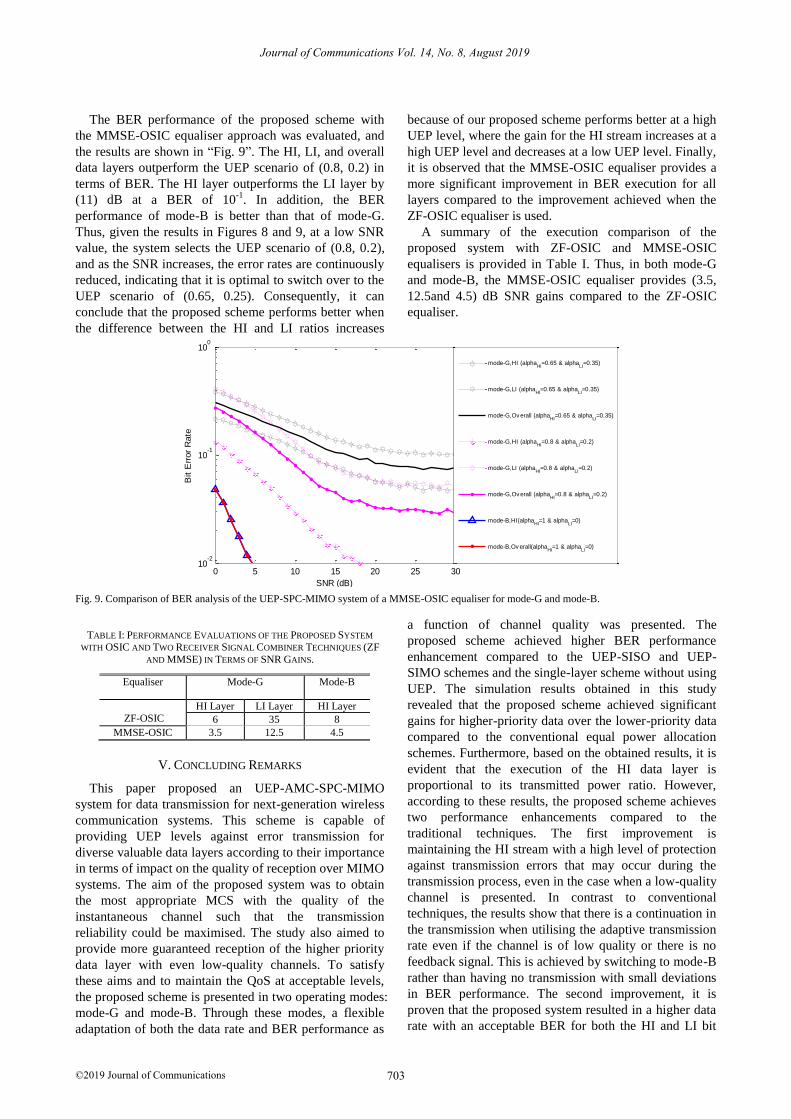
The BER performance of the proposed scheme with
the MMSE-OSIC equaliser approach was evaluated, and
the results are shown in “Fig. 9”. The HI, LI, and overall
data layers outperform the UEP scenario of (0.8, 0.2) in
terms of BER. The HI layer outperforms the LI layer by
(11) dB at a BER of 10-1
. In addition, the BER
performance of mode-B is better than that of mode-G.
Thus, given the results in Figures 8 and 9, at a low SNR
value, the system selects the UEP scenario of (0.8, 0.2),
and as the SNR increases, the error rates are continuously
reduced, indicating that it is optimal to switch over to the
UEP scenario of (0.65, 0.25). Consequently, it can
conclude that the proposed scheme performs better when
the difference between the HI and LI ratios increases
because of our proposed scheme performs better at a high
UEP level, where the gain for the HI stream increases at a
high UEP level and decreases at a low UEP level. Finally,
it is observed that the MMSE-OSIC equaliser provides a
more significant improvement in BER execution for all
layers compared to the improvement achieved when the
ZF-OSIC equaliser is used.
A summary of the execution comparison of the
proposed system with ZF-OSIC and MMSE-OSIC
equalisers is provided in Table I. Thus, in both mode-G
and mode-B, the MMSE-OSIC equaliser provides (3.5,
12.5and 4.5) dB SNR gains compared to the ZF-OSIC
equaliser.
0 5 10 15 20 25 3010
-2
10-1
100
SNR (dB)
Bit E
rror
Rate
mode-G,HI (alphaHI
=0.65 & alphaLI
=0.35)
mode-G,LI (alphaHI
=0.65 & alphaLI
=0.35)
mode-G,Ov erall (alphaHI
=0.65 & alphaLI
=0.35)
mode-G,HI (alphaHI
=0.8 & alphaLI
=0.2)
mode-G,LI (alphaHI
=0.8 & alphaLI
=0.2)
mode-G,Ov erall (alphaHI
=0.8 & alphaLI
=0.2)
mode-B,HI(alphaHI
=1 & alphaLI
=0)
mode-B,Ov erall(alphaHI
=1 & alphaLI
=0)
Fig. 9. Comparison of BER analysis of the UEP-SPC-MIMO system of a MMSE-OSIC equaliser for mode-G and mode-B.
TABLE I: PERFORMANCE EVALUATIONS OF THE PROPOSED SYSTEM
WITH OSIC AND TWO RECEIVER SIGNAL COMBINER TECHNIQUES (ZF
AND MMSE) IN TERMS OF SNR GAINS.
V. CONCLUDING REMARKS
This paper proposed an UEP-AMC-SPC-MIMO
system for data transmission for next-generation wireless
communication systems. This scheme is capable of
providing UEP levels against error transmission for
diverse valuable data layers according to their importance
in terms of impact on the quality of reception over MIMO
systems. The aim of the proposed system was to obtain
the most appropriate MCS with the quality of the
instantaneous channel such that the transmission
reliability could be maximised. The study also aimed to
provide more guaranteed reception of the higher priority
data layer with even low-quality channels. To satisfy
these aims and to maintain the QoS at acceptable levels,
the proposed scheme is presented in two operating modes:
mode-G and mode-B. Through these modes, a flexible
adaptation of both the data rate and BER performance as
a function of channel quality was presented. The
proposed scheme achieved higher BER performance
enhancement compared to the UEP-SISO and UEP-
SIMO schemes and the single-layer scheme without using
UEP. The simulation results obtained in this study
revealed that the proposed scheme achieved significant
gains for higher-priority data over the lower-priority data
compared to the conventional equal power allocation
schemes. Furthermore, based on the obtained results, it is
evident that the execution of the HI data layer is
proportional to its transmitted power ratio. However,
according to these results, the proposed scheme achieves
two performance enhancements compared to the
traditional techniques. The first improvement is
maintaining the HI stream with a high level of protection
against transmission errors that may occur during the
transmission process, even in the case when a low-quality
channel is presented. In contrast to conventional
techniques, the results show that there is a continuation in
the transmission when utilising the adaptive transmission
rate even if the channel is of low quality or there is no
feedback signal. This is achieved by switching to mode-B
rather than having no transmission with small deviations
in BER performance. The second improvement, it is
proven that the proposed system resulted in a higher data
rate with an acceptable BER for both the HI and LI bit
Equaliser Mode-G Mode-B
ZF-OSIC
HI Layer LI Layer HI Layer
6 35 8
MMSE-OSIC 3.5 12.5 4.5
Journal of Communications Vol. 14, No. 8, August 2019
703©2019 Journal of Communications
streams for high-quality channels. In addition, there is no
transmission in the traditional schemes for low-quality
channels. In addition, MSD receiver accompanied by the
OSIC technique is employed using two linear RSC
techniques, namely, ZF and MMSE, thus, it is shown that
the RSC approaches with SPC outperformed the scheme
without SPC.
ACKNOWLEDGMENT
The research was supported by the Ministry of
Education, Malaysia under the grant scheme No.
FRGS/1/2018/TK04/UMP/02/11.
REFERENCES
[1] Y. G. Hua, S. Dongxu, and L. O. K. Victor, “Adaptive
sub-channel allocation based UEP for video transmission
in space-time coded OFDM systems,” in Proc. IEEE 15th
International Symposium on Personal, Indoor and Mobile
Radio Communications, vol. 4, pp. 3054-3058, 2004.
[2] L. Shuying, Z. Yaqin, H. Liang, W. Zhilu, and L.
Yuanyuan, “A novel STBC-DCSK transmission scheme
for scalable video with unequal error protection property,”
in Proc. IEEE International Conference on Consumer
Electronics (ICCE), 2016.
[3] H. Changcai and W. Weiling, “UEP schemes for
multimedia transmission in space-time coded systems,” in
Proc. IEEE International Conference on Communications,
Circuits and Systems, pp. 602-606, 2007.
[4] L. Yang, Z. Hui, Z. Bin, W. Wenbo, and W. Bin, “A
novel unequal-error-protected STBC design for
multimedia transmission,” in Proc. IEEE 73rd Vehicular
Technology Conference (VTC Spring), 2011, pp. 1-5.
[5] J. Jose and S. M. Sameer, “A new unequal error
protection technique for scalable video transmission over
multimedia wireless networks,” in Proc. IEEE
International Conference on Signal Processing,
Informatics, Communication and Energy Systems, 2015.
[6] S. O. Hazim and X. Wei, “A novel unequal error
protection scheme for 3-D video transmission over
cooperative MIMO-OFDM systems,” EURASIP Journal
on Wireless Communications and Networking , 2012, pp.
1-15.
[7] K. S. Wasan, I. Mahamod, N. Rosdiadee, and E. S. A.
Ayman, “Survey of adaptive modulation scheme in
MIMO transmission,” Journal of Communications, vol.
7, no. 12, 2012.
[8] R. Fantacci, D. Marabissi, D. Tarchi, and I. Habib,
“Adaptive modulation and coding techniques for OFDMA
systems,” IEEE Transactions on Wireless
Communications, vol. 8, no. 9, pp. 4876-4883, 2009.
[9] K. S. Wasan, I. Mahamod, N. Rosdiadee, and E. S A.
Ayman, “Throughput performance of adaptive
modulation and coding scheme with link adaptation for
MIMO-WiMAX downlink transmission,” Journal of
Asian Scientific Research, vol. 2, no. 11, pp. 641-650,
2012.
[10] T. Jun, P. Li, and M. Xiao, “Superposition coded
modulation with peak-power limitation,” IEEE
Transactions on Information Theory, vol. 55, no. 6, 2009.
[11] H. P. Adam and W. Tianbin, “Superposition modulation:
Myths and facts,” IEEE Communications Magazine, vol.
49, no. 12, pp. 110-116, 2011.
[12] P. P. Bergmans and T. M. Cover, ”Cooperative
broadcasting,” IEEE Transaction on Information Theory,
vol. 20, no. 3, pp. 317-324, 1974.
[13] G. Karabulut and A. Yongacoglu, “Superposition block
coded modulation,” in Proc. IEEE Canadian Conference
on Electrical and Computer Engineering(CCECE), 2013
vol. 3, pp. 1629-1632.
[14] M. Jan, S. Robert, L. Lutz, G. H. Wolfgang, and H. A.
Peter, “Multiple-Antenna techniques for wireless
communications - a comprehensive literature survey,”
IEEE Communications Surveys& Tutorials, vol. 11, no. 2,
pp. 87-105, 2009.
[15] R. Fa and R. C. D Lamare, “Multi-branch successive
interference cancellation for MIMO spatial multiplexing
systems: Design, analysis and adaptive implementation,”
IET Communications, vol. 5, no. 4, 2011.
[16] H. Thomas, L. Peng, R. C. D. Lamare, and W. Stephen,
“Multi-Feedback successive interference cancellation
with dynamic log-likelihood-ratio based reliability
ordering,” in Proc. Tenth International Symposium on
Wireless Communication Systems, 2013, pp. 696-700.
[17] H. Nohand and F. Xavier, “Massive MIMO wireless
networks: An overview,” Journal of Electronics, vol. 6,
no. 63, pp. 1-29, 2017.
Wasan Kadhim Saad received the B.Sc.
degree in Electrical and Electronic
Engineering / Electronic &
Communication from the University of
Technology, Baghdad, Iraq, 1997. She
received the M.Sc degree in the Satellite
Communication Engineering from the
University of Technology, Baghdad, Iraq,
2005, and her Ph.D. in Electrical, Electronics, and System
Engineering from the University Kebangsaan Malaysia (UKM),
Faculty of Engineering and Build Environment, Bangi, Selangor,
Malaysia, 2017. She is currently working in the Al-Furat Al-
Awsat Technical University, Engineering Technical College-
Najaf, Iraq. Her research interests include Wireless
Communications and Networking, Cognitive Radio Networks
and Image Processing.
Waheb A. Jabbar received the B.Sc. in
Electrical Engineering from the
University of Basrah, Iraq, in 2001, the
M.Eng. in Communication & Computer
and the Ph.D. in Electrical, Electronics,
and System Engineering from Universiti
Kebangsaan Malaysia (UKM), Bangi,
Selangor, Malaysia, in 2011 and 2015
respectively. He is currently a Senior Lecturer in the Faculty of
Engineering Technology, Universiti Malaysia Pahang (UMP),
Gambang, Pahang, Malaysia. His research interests include
Journal of Communications Vol. 14, No. 8, August 2019
704©2019 Journal of Communications

Routing Protocols in Ad Hoc Networks, Mobile
Communications and Wireless Networking. He also has keen
interest in Internet of Things applications and Smart City.
Bashar J. Hamza received the B.Sc.
degree in Communication Engineering
from Al-Furat Al-Awsat Technical
University, Engineering Technical
College-Najaf, Iraq, 2002. He received
the M.Sc degree in the Communication
Engineering from the University of
Technology, Baghdad, Iraq, 2005, and
His Ph.D in Wireless Communication Engineering from the
Universiti Putra Malaysia (UPM), Faculty of Engineering, 2011.
He is currently working in the Al-Furat Al-Awsat Technical
University, Engineering Technical College-Najaf, Iraq. His
research interests include Vertical handover, UMTS network,
WLAN network and Heterogeneous network between
UMTS/WLAN.
Journal of Communications Vol. 14, No. 8, August 2019
705©2019 Journal of Communications