adaptive relaying introduction application advantages adaptive system impedance model improved...
TRANSCRIPT

1
Adaptive Relaying
Introduction
Conventional relays have fixed setting parameters and therefore it becomes difficult
to comply with the protection requirements in variable operation conditions in a power
system. A solution to this problem is the adaptive protection, which can vary its setting
parameters or its operating characteristics in response to changes in the power system.
Adaptive protection is defined by Horowitz, Phadke and Thorp as “a protection
philosophy which permits and seeks to make adjustments to various protection functions in
order to make them more attuned to prevailing power system conditions.”
This implies updating of the relay settings, which represent a change in the power
system topology. This change in power system topology is mainly due to the following
reasons:
1. Deliberate system switching, for example, isolation of a part of the equipment for
maintenance.
2. Unplanned system switching, for example, removal of a fault by a relay from a
healthy power system.
In these cases, the power system topology gets changed but the system protection
settings remain the same as they before the modifications, which is why the latter may not be
able to adequately protect the current system. Once the system topology is changed, the
settings of the system devices should be updated as soon as possible to protect the system
against new faults. This can be achieved by applying the adaptive protection scheme.
Adaptive relaying can be utilized in the following areas:
i. Automatic circuit breaker reclosing control.
ii. Power transformer protection.
iii. Multi-terminal transmission line protection.
iv. Relay settings.

2
Specifically, adaptive protection is applied to dynamically determine the pick-up
current and time multiplier in overcurrent relays. These parameters can be determined
through optimization techniques. Continuous real-time simulations of the power system also
need to be done to reconfigure the protection system. Thus, as and when there is a change in
the power system, continuous real-time simulations help protection devices to get updated
automatically.
Adaptive protection systems are expected to perform the following functions:
i. Relays should only operate for faults in their respective zone of protection, as defined
by the direction that the relay supervises.
ii. If both the relays sense a fault in their respective zones of protection. The relay with
the shorter time delay or the relay subject to the longer fault current should trip first.
iii. As the power system topology changes, the relay will automatically switch to the
appropriate relay group for proper power system protection.
It is obvious that adaptive protection is an old concept, which is substantiated by the
fact that directional relaying schemes adapt the direction of the fault current while time-delay
overcurrent relays adapt their operating to fault magnitude. But these old concepts represent
the permanent characteristics of a relay or relay system. These characteristics are part of the
original designs of the installations used to perform a given function.
The relay setting has to adapt itself to the real-time system as and when the system
conditions change. The advantages and applications of adaptive protection schemes are
shown in the following table.

3
Application advantages
Adaptive system impedance model Improved reliability
Adaptive sequential instantaneous
tripping Faster back-up protection
Adaptive multi-terminal relay coverage Improve zone settings
Adaptive zone-1 ground distance Greater sensitivity to high resistance
ground fault
Adaptive re-closing Faster restoration following incorrect
trips
Variable breaker-failure timing
Improvement in back-up timing margins
and elimination of unnecessary tripping
of back-up breaker
Adaptive last-resort islanding Facilitation of load restoration
Adaptive internal logic monitoring Improve relaying reliability
Relay setting co-ordination checks Optimization of the co-ordination
Adaptive Relaying
The concept of adaptive relaying is that many relay settings are dependent upon
assumed conditions on the power system. In order to cover all possible scenarios that the
protection system may have to face, the actual protection settings in use are often not optimal
for any particular system state. If an optimal setting is desired for an existing condition on the
power network, then it becomes necessary for the setting to adapt itself to the real-time
system states as the system conditions change.

4
When the power system is in a normal (healthy) state, there is sufficient generation and
spinning reserve to meet the connected load, and transmission facilities are robust enough to
provide strong alternative paths for power flow in the event of contingencies. In such a state,
the greatest danger to the power system is instability resulting from faults that are not cleared
quickly. It is therefore normal practice to design the protection system with a very high level
of dependability, thereby making sure that all faults will be cleared by primary protection
systems. The penalty for making the system highly dependable is a loss of security: the
protection system may operate unnecessarily, removing system components that were not
faulted. Such over-tripping is not harmful for a robust power system. However, when the
power system is not robust because of prevailing stressful conditions, the bias toward
dependability is harmful. Then the system can ill afford to lose an unfaulted transmission
facility in error. One would now prefer to have a protection system that is biased in favor of
security. Thus, one would reduce risk of false trips and accept a reduction in dependability. A
very powerful adaptive relaying concept helps realize this flexible dependability-security
balance as shown in Figure 1.
Based upon an assessment of the condition of the network made at the energy control
center of the power system, a decision is made as to whether the power system is in a normal
healthy state or in a stressed state. This state characterization is made known to the protection
systems at key facilities. The protection systems in those facilities have the ability to alter the
balance between security and dependability based upon the signal from the energy control
center by changing the arbitration strategies among available relay outputs.

5
Speed as Function of Fault Location
The concept of relay operating speed as a function of the fault magnitude is well known
and is a natural result of the traditional time delay over-current relays that provide an inverse
time versus current-magnitude relationship. However, distance relays, which are the
fundamental component of almost all EHV transmission line protection, do not perform in
this manner. For fault impedances that fall within the relay characteristic, the operating speed
of the distance relay is relatively constant. The operating speed must allow enough time so
the relay can ignore the non-60 (or 50) Hz frequency components that always accompany a
fault in order to make a correct decision. Digital relays can accommodate the errors caused by
non-fundamental frequency signals by dynamically adjusting its operating speed as the
operating speed (sample window) gets larger or smaller. For instance, a relay using all of the
data samples in one period of the fundamental frequency component could be set to see 80–
90% of the line to assure dependable operation in the presence of noise. With half the
samples (i.e., in half cycle), the calculation error is greater and the relay would be set to see
only 60% of the line. In a quarter-cycle the error is still greater and the reach would be set to
see less of the line. However, in each instance the operating speed of the relay is significantly
increased although the reach of the relay is reduced. Close in faults, with their more
damaging impact, are thus removed faster.
Fault Analysis and Protection Determination
Faults can be analyzed by applying them to various locations in a modeled power system and
the recording the resulting fault currents and voltages. The results of this fault analysis help
decide the determination of the level protection. Generally, for simulation purposes, fault
locations are kept at each bus and the mid-point of each line. The fault currents and voltages
for each type of fault and location represent the fault analysis results. In order to determine
the adaptive protection settings, fault analysis results are found for all the possible system
configurations.
In order to realize the system protection, the relay settings are selected on the basis of the
power system configuration and fault conditions, once the fault analysis has been completed.
A table of different power system topologies consisting of associated relay settings is
organized in such a manner as to ensure that the sets of relay settings for a particular relay

6
location are similar. Each group of similar relay settings are analyzed to arrive at a set of
common settings which are useful for that group and to mange all situations that need to be
covered.
The adaptive relaying scheme operates very rapidly and the relays can communicate with one
another to indicate failures, suppress operation and suitably isolate a fault.
These schemes can also facilitate communication between devices other than relays. Local or
remote computers can interface with digital relays and allow humans to easily interact with
the relay. Any digital aspect of the relay including current settings, operation logs and event
reports can be downloaded by computers, which can also carry out the requisite changes in
the current settings. The detailed can be saved in a separate file for future reference and use.
Relay-to-relay and relay-to-computer communication paths for a digital relay are shown in
the following Figure.
7
ADAPTIVE TECHNIQUES
The use of numeric techniques for protective relays has allowed the protection
algorithms to become adaptive to conditions on the power system. The use of these adaptive
algorithms can increase both the security and the dependability of the protective system
compared to similar electronic and electromechanical relay systems. Several of these adaptive
techniques will are discussed in the following sections.
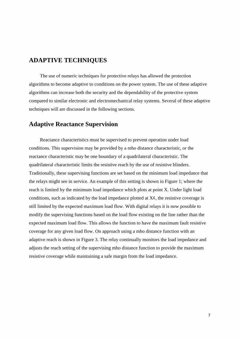
Adaptive Reactance Supervision
Reactance characteristics must be supervised to prevent operation under load
conditions. This supervision may be provided by a mho distance characteristic, or the
reactance characteristic may be one boundary of a quadrilateral characteristic. The
quadrilateral characteristic limits the resistive reach by the use of resistive blinders.
Traditionally, these supervising functions are set based on the minimum load impedance that
the relays might see in service. An example of this setting is shown in Figure 1; where the
reach is limited by the minimum load impedance which plots at point X. Under light load
conditions, such as indicated by the load impedance plotted at X¢, the resistive coverage is
still limited by the expected maximum load flow. With digital relays it is now possible to
modify the supervising functions based on the load flow existing on the line rather than the
expected maximum load flow. This allows the function to have the maximum fault resistive
coverage for any given load flow. On approach using a mho distance function with an
adaptive reach is shown in Figure 3. The relay continually monitors the load impedance and
adjusts the reach setting of the supervising mho distance function to provide the maximum
resistive coverage while maintaining a safe margin from the load impedance.

8
Adaptive reach using an mho distace function
Adaptive Polarizing Memory
Some form of polarizing voltage memory is a common feature for mho distance relays.
The memory voltage serves three main functions:
1. Allows the distance relays to operate for zero voltage three phase faults in front of the
relay,
2. Prevents the relay from operating for zero voltage three phase faults behind the relay,
3. Give the relay a variable characteristic.
In the past, the duration of the memory voltage was typically for a predetermined time,
or for an “infinite” time. One possible problem area with the fixed memory time is for faults
beyond the reach of the Zone 1 functions. On lines with high source to line ratios, magnitude
of the steady state fault voltage at the relay for three phase faults at the remote end of the line
may be less than the voltage required for the relay to operate. For these conditions, the
overreaching step distance backup functions may not operate if the time delay is greater than
the fixed memory time. In digital relays, the memory time can be made adaptive based on the
fault duration. One possible adaptive memory logic scheme is described below.
If the positive sequence voltage is less than 10% of rated during a fault, the relay will
continue to use the pre-fault memory voltage to polarize the distance functions. The pre-fault
memory voltage will be used until the positive sequence voltage increases above 10%, or
until the fault detector resets. Note that the fault detector is sealed-in when any distance

9
function is picked up. If the relay uses positive sequence voltage polarizing for all distance
units, this change will not affect the performance for other than three phase faults because the
magnitude of the positive sequence voltage will be above 10% of nominal (»7 V rms) for all
unbalanced faults.
Relay Design
Electromechanical and solid-state relays do not determine the exact location of a fault.
Instead, they establish a zone of protection for which the relay will operate. This zone of
protection is defined by the relay characteristic; i.e., a circle or some other geometric figure.
This characteristic can be entered during other system phenomena such as changing loads,
generator loss-of-field, or system stability swings as shown in Figure 2 for which some
provision must be made to avoid an incorrect trip. Digital relays need not duplicate the
traditional relay characteristic and instead can calculate the exact location of a fault and are,
therefore, not susceptible to such incorrect operations.
Below are some examples of other relaying problems and possible counter-measures.
1. Adaptive control of defective relays.
This was the first advantage recognized for digital relays. The relay can monitor itself
and give immediate alarm that a correction is needed.

10
2. Load effect. One of the most significant causes of incorrect distance relay tripping is
the fact that the relay characteristic under severe system conditions can be encroached
upon by heavy loads. The solution is to monitor the load and eliminate it from the
digital relay fault-processing algorithm.
3. Cold load pickup. The restoration of load, particularly on distribution circuits, results
in current magnitudes that exceed the normal instantaneous relay settings. Logic can
be employed to recognize the length of an outage and the magnitude of the load
pickup current. Today’s solution is to remove the instantaneous relay for a period of
time after the circuit is restored. Digital relays can have their setting automatically
adjusted to maintain protection.
4. End-of-line protection. Instantaneous relays must not overreach a line to avoid loss
of coordination. Recognizing that the remote breaker has opened and transmitting this
fact to the other end allows the instantaneous relay setting to be adjusted for this stub
fault, protecting the entire line instantaneously rather than relying on a time-delay
over-current relay.
5. Multi-terminal line protection. Traditional setting philosophy requires that Zone 1
must under-reach the remote terminal to avoid loss of coordination and is therefore set
with no in-feed. Zones 2 and 3 must overreach to insure 100% line protection and are
set with in-feed. Transmitting the status of either the breakers or the actual current to
all terminals allows the setting to avoid potentially damaging compromises.
6. Transformer protection. Aside from the problem of harmonics, transformer
differential relays must accommodate tap changes, CT ratio mismatch, and other
errors. Adaptive relays can monitor the actual currents and adjust the percentage
setting for them.
Adaptive Relay Settings
The objective of adaptive relay settings is to minimize the compromise that are
accumulated due to considering several conditions simultaneously, by allowing the relays to
responds only to actual conditions. Digital relays, whose settings are resident in software and
can be set remotely via communication, can automatically adjust to many changes in system
conditions. Thus, they can be set to respond to 'existing' network conditions, that change from
time to time, and to operate faster for various types of fault conditions.

11
A study presented in [Jam98] illustrated the benefits of applying adaptive relay settings.
The paper compared the protection operation for a network protected by overcurrent relays,
with and without adaptive reviewing of relay settings. Their results show that for adaptive
relay settings:
Mean operating time of primary operations is 18.4% faster.
Mean operating time for back-up operation is 18.4% faster.
Individual primary protection, as well as back-up protection, consistently operates
faster.
These results demonstrate that setting the relay for 'existing' network conditions results
in speedier operation of the relays. However the relay settings need to be computed more
often because of possible changes that may occur in the state of the network. Some other
benefits offered by adaptive relay setting are as follows:
Better transmission line loading due to significantly improved speed of relaying
Improved life expectancy of transmission lines and switch gears because they are
exposed to extreme fault conditions for shorter times
Permissive over-loading of transmission lines by increasing the pickup setting of the
over-current relays to prevent tripping when service is restored following an outage.
Components of an adaptive protection system
Every adaptive protection consists of three main components: hardware,
communication system and software.
1. Hardware:
The hardware of adaptive protections is mainly protective relays' hardware. The possible
hardware architectures are:
A single computer performs all the functions in a substation. With this alternative,
since all protection operations depend on a single computer, which can cause a serious
unavailability problem, it is hard to convince protection engineers to accept this
alternative.

12
A set of relays implements a specified protection function. For example, the
protection of a single transmission line may consist of over-current, distance and
traveling-wave-based relays. This alternative is in close conformation with existing
protection practices.
A relay with multiple processors to realize a single protection scheme. For example, a
relay may be realized by multiple processors to achieve higher computational speed.
Multi-Layer Multi-Agent Architecture
Adaptive protection is realized with multi-layer multi-agent architecture for large-scale
transmission networks. The architecture has the following features:
1. Intelligent adaptive methods allowing protective devices to adapt to changing system
conditions.
2. Each agent may have only a local view of the system, but the team of agents (i.e.
multi-agent system) can perform wide-area protective schemes through autonomous
and cooperative action of the agents.
3. The cooperation of multi-agents enables the flexible utilizations of all hardware
resources by any equipment, so that various adaptive protection functions are realized.
(01364859)
Multi-layer multi-agent system for adaptive protect is made up of three layers, the system,
substation, and equipment. Each of the layers is made up of a group of software agents that
perform different functions. The communication between the agents is what allows for the
adaptive protection functions.

13

14

15
The lowest (equipment) layer is required to act quickly to disturbances while the higher
layers view the whole system. A multi-agent system is a distributed and coupled network of
intelligent hardware and software agents that are working together to achieve a global goal. A
description of the role of the agent in a multi-layer protection system is as follows:
The measurement agent observes the current and voltage levels, checks the status of
isolation devices and circuit breakers, and transfers the data to the protector and mobile
(collector) agent. The protector agent collects the power system information and detects if a
fault occurred and isolates the fault to a zone. When a fault is detected the performer trips the
circuit breaker isolating the faulted section. The mobile agent communicates between the
software agents and system equipment for data transfer. The region agent collects the data
from the lower layers and sends the information to the management agents and the higher
layer. The management agent calculates the setting of the relays depending on the power
systems state and passes them back to the protector agents. Essential data is sort by the
system agent to recognize a disturbance and the data is transfer to the evaluation agent. The
evaluation agent monitors the performance of the protection system if it determine that a lack
of protection capability it send a request to the management agent to modify the necessary
values.
2. Communication and Control:
The generating units and the loads of a power system are usually far apart and the
transmission system inter-connects them. However, the control is centralized and many
control decisions require system-wide knowledge. Each substation has complete information
on its current status, but not on that of any other substation. data is gathered from major
substations and is sent to a central control center for processing and further action. At any
given time, only the control center has the up-to-date performance data profile of the system
and the computing power to process the data.
3. software:
The software part of an adaptive protection system is on-line relay coordination
programs. The software should be able to:
o review existing settings;

16
o re-compute the settings in case of a contingency or of localized changes in
power generation or load;
o re-compute the settings to accommodate the slowly varying network
conditions;
o check the backup relay operation for improving reliability.

17
Literature Survey:
1. An Adaptive Protection Scheme for Optimal
Coordination of Overcurrent Relays.
" A.Y. Abdelaziz , H.E.A. Talaat , A.I. Nosseir , Ammar A. Hajjar."
In this paper, the authors suggest an adaptive protection scheme for optimal
coordination of overcurrent relays in interconnected power networks by applying a linear
programming technique.
The general relay coordination problem can be stated as a parametric optimization
problem. The objective function of operating times of the primary relays is minimized subject
to keeping the operation of the backup relays coordinated. One possible approach to achieve
minimum shock to the system due to faults would be to minimize a sum of the operating
times of all primary relays hoping that the operating times of individual primary relays would
be close to the minimum individual operating times that might be possible.
The adaptive relaying scheme
Fig. 2 shows the functional block diagram of the adaptive relaying scheme proposed for
overcurrent protection of the power system. Similar configurations of relays and computers
are used at other substations. The
relays sample line currents via current transformers. Each relay possesses quantized samples
and calculates voltage and current phasors. Under normal operating conditions, each relay
provides the measurements to the substation control computer at regular intervals.
The SCADA system checks the status of local isolators and circuit breakers and provides the
information to the substation computers. In addition to communicating with the relays, the
station computer pass on the collected information to the central computer at pre-specified
intervals (e.g. 1 h).

18
The central computer estimates the system state and decides whether or not the relay settings
should be changed. If it decides to change the settings, it will calculate the new settings and
conveys them to the relays via the substation control computers. The relays implement the
new settings and send confirmation messages to the central computer via substation
computers. If the central computer decides not to change the settings, the decision will be
communicated to the relays for the purpose of sharing information and confirming that
communication facilities are working properly.

19
Algorithm for adaptive coordination
Fig. 3 illustrates the flowchart of the developed MATLAB algorithm for the adaptive
coordination of the overcurrent relays. Each block of the flowchart is explained as follows:
1. Topology processor
The topology processor tracks the network topology over the time. The circuit breaker
status information is the main input to this module. The topology processor feeds the
network information to the load flow program and the fault analysis program.
2. Optimal coordination procedure

20
Using a linear programming technique (Active Set Strategy two-phase method) as
follows: In phase I, a feasible solution is obtained and in phase II, the optimal solution is
found.
3. Transfer settings to the relays
In adaptive coordination of overcurrent relays, it is assumed that all relays are of
digital type and that there is a communication channel between them and the substation
control computers (optic-fiber cables) as shown in Fig. 2. Hence, once the relay settings
are calculated, these are communicated to the respective relays.
4. Monitoring
The power system is continuously monitored, using SCADA system, for any change
operational or topological. If the change detected is an operational change, the computer
will restart the coordination process from the load flow program and if the change is due
to a topological change, the procedure will be restarted from the topology processor.

21

22
Adaptive relays for overhead line protection
V. Calderaro, V. Galdi, A. Piccolo , P. Siano
In this paper an adaptive procedure is presented in order to manage power distribution
systems according to dependability or security requirements. In particular, a procedure to
obtain an inverse time trip curve by means of a microprocessor, connected to a relay, is
presented. The procedure adapts the trip characteristic depending on the conductor
temperature, wind speed, emissivity and solar absorbity and is implemented on a
microprocessor Rabbit 2200 considering a Drake conductor, 795 kcmil 26/7 ACSR.
Adaptive concept and the architecture of the protection system:
The proposed architecture, shown in Fig. 1, consists of a breaker, sensors, useful in
obtaining current value and ambient conditions and an external microprocessor, which
computes the trip characteristic according to the actual conditions. The variables causing the
change of the operative conditions are temperature, wind speed and solar absorbity. The
breaker protects an overhead line by faults and overloads.
The sensors measure line current, wind speed and solar absorbity. Starting from an
average current value, obtained by the acquisition of current values for a ∆t time. the

23
microprocessor evaluates the conductor temperature by means of previously loaded
algorithms and considering the history previous to the measurement.
According to an adaptive procedure, described in the next paragraph, a new trip
characteristic is evaluated and stored into the relay. The adaptive procedure, in this way, aims
at overcoming the protection system management based on worst case situation by means of
static rating trip values.

24
Comparative Evaluation of Adaptive and
Conventional Distance Relay for Parallel
Transmission Line with Mutual Coupling
S.G. Srivani, Chandrasekhar Reddy Atla, K.P.Vittal
This paper presents the development of adaptive distance relay for protection of
parallel transmission line with mutual coupling. The proposed adaptive relay, automatically
adjusts its operation based on the acquisition of the data from distance relay of adjacent line
and status of adjacent line from line circuit breaker IED (Intelligent Electronic Device). The
zero sequence current of the adjacent parallel transmission line is used to compute zero
sequence current ratio and the mutual coupling effect is fully compensated. The relay adapts
to changing circumstances, like failure in communication from other relays and non-
availability of adjacent transmission line.
DEVELOPMENT OF ADAPTIVE DISTANCE RELAY
The proposed adaptive relaying scheme on each protected line accesses the three-phase
voltage and current signals of the protected line. In addition, the zero sequence current and
line operating status of the paralleled lines at the substation where the distance relay is
located will be used by the scheme. The parallel line’s zero sequence current could be
25
obtained either through additional cabling, direct communication link between relays, or
substation local networks. The parallel line’s operating status could be obtained by accessing
the circuit breaker’s auxiliary contacts and/or parallel line’s voltage/current level detection or
substation PLC (programmable logic controller). The scheme automatically adapts its
operation based on the signal availability from the parallel lines to achieve an optimal
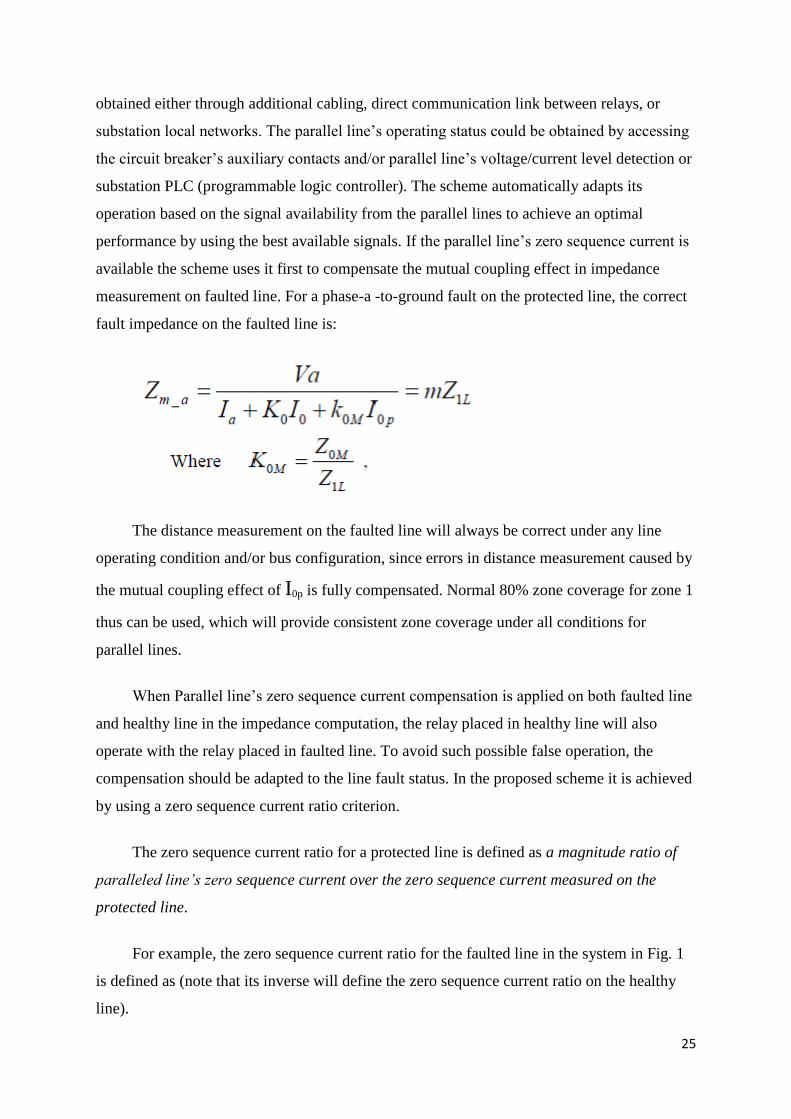
performance by using the best available signals. If the parallel line’s zero sequence current is
available the scheme uses it first to compensate the mutual coupling effect in impedance
measurement on faulted line. For a phase-a -to-ground fault on the protected line, the correct
fault impedance on the faulted line is:
The distance measurement on the faulted line will always be correct under any line
operating condition and/or bus configuration, since errors in distance measurement caused by
the mutual coupling effect of I0p is fully compensated. Normal 80% zone coverage for zone 1
thus can be used, which will provide consistent zone coverage under all conditions for
parallel lines.
When Parallel line’s zero sequence current compensation is applied on both faulted line
and healthy line in the impedance computation, the relay placed in healthy line will also
operate with the relay placed in faulted line. To avoid such possible false operation, the
compensation should be adapted to the line fault status. In the proposed scheme it is achieved
by using a zero sequence current ratio criterion.
The zero sequence current ratio for a protected line is defined as a magnitude ratio of
paralleled line’s zero sequence current over the zero sequence current measured on the
protected line.
For example, the zero sequence current ratio for the faulted line in the system in Fig. 1
is defined as (note that its inverse will define the zero sequence current ratio on the healthy
line).

26
By setting a proper threshold equal to 1.0 plus some margin so that the compensation
will not be performed when the ratio on the protected line is above the threshold, the relay
false operation on the healthy line for close-in faults on an adjacent parallel line could be
effectively prevented.
when the parallel line’s zero sequence current is not available due to local technical
problems to the relay for various reasons ,the proposed adaptive scheme adopts to use parallel
line’s operating status signal, for an improved performance. A relay could make proper zone
setting and/or zero sequence compensation factor adjustment to take into account of the
mutual coupling effect corresponding to each line operating status.
The sequence network in Fig. 3 corresponds to the line operating condition in Fig. 2(a).

27
In Fig. 3, Z AB0 = Z L0 is assumed, the accurate zero sequence compensation factor in (1)
at m the fault location under this condition is,
This is a function of the fault location, system, and line impedance. Using k 0with I 0 in
the fault impedance
Similarly, the zero sequence current compensation factor for one parallel line switched
off and grounded at both ends could be derived. The zero sequence network for one parallel
line switched off and grounded at both ends is shown in Fig. 4.

28
The accurate zero sequence compensation factor at the fault location m under this
condition is given by
In the case that both parallel line’s zero sequence current and line operating status
signals are not accessible, a default zero sequence compensation factor (K 3), based on the
worst case scenario, will be used by the new adaptive relay to ensure a reliable operation of
the relay. This operation mode achieves the same performance level as conventional distance
relays operating on the parallel lines.
An exemplary flowchart illustrating how the new adaptive scheme works is shown in
Fig. 5. In this flowchart, the adaptive scheme first ascertains whether the parallel line’s zero
sequence current is available. If available, the zero sequence current ratio is used to determine
the line fault status. The parallel line’s zero sequence current will be used for faulted line
impedance computation, but will not be used in healthy line’s impedance calculation.
When the adjacent parallel transmission line’s current is not available, the parallel line’s
operating status at the relay location is used to select the proper zero sequence compensation
factors. The relay logic program follows the sequence shown in flowchart, for both line in

29
operation condition, and for one line switched off condition. In the case that both the parallel
line’s current and operating status are not accessible, the scheme uses the default zero
sequence current compensation factor.

30
References
1. Jerel Culliss, Alan Franklin, David Majok, "Adaptive Protection: Background, Uses,
and Methods."
2. S. M. Madani, "Analysis and Design of Power System Protections Using Graph
Theory."
3. Ravindra P. Singh, " Digital Power System Protection ".
4. S.H. Horrowiittz and A.G. Phadke, "Boosting Immunity to Blackouts." , IEEE power
& energy magazine. september/october 2003.
5. A.K. Jampala, S.S Venkata and M.J. Damborg, "Adaptive transmission protection:
concepts and computational issues", IEEE Transactions on power delivery, Vol. 4, N.
1, January 1989, pp. 177-185.
6. A.Y. Abdelaziz , H.E.A. Talaat , A.I. Nosseir , Ammar A. Hajjar. , " An Adaptive
Protection Scheme for Optimal Coordination of Overcurrent Relays."
7. V. Calderaro, V. Galdi, A. Piccolo , P. Siano. , " Adaptive relays for overhead line
protection "
8. S.G. Srivani, Chandrasekhar Reddy Atla, K.P.Vittal. , "Comparative Evaluation of
Adaptive and Conventional Distance Relay for Parallel Transmission Line with
Mutual Coupling "