adaptive reuse: plastic bottle construction
DESCRIPTION
A comprehensive analysis of adaptive reuse plastic bottle construction techniques.TRANSCRIPT
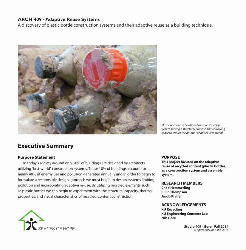
ARCH 409 - Adaptive Reuse SystemsA discovery of plastic bottle construction systems and their adaptive reuse as a building technique.
Purpose StatementIn today’s society around only 10% of buildings are designed by architects
utilizing “first-world” construction systems. These 10% of buildings account for nearly 40% of energy use and pollution generated annually and in order to begin to formulate a responsible design approach we must begin to design systems limiting pollution and incorporating adaptive re-use. By utilizing recycled elements such as plastic bottles we can begin to experiment with the structural capacity, thermal properties, and visual characteristics of recycled-content construction.
PURPOSEThis project focused on the adaptive reuse of recycled content (plastic bottles) as a construction system and assembly system.
RESEARCH MEMBERSChad HemmerlingCulin ThompsonJacob Pfeifer
ACKNOWLEDGEMENTSKU RecyclingKU Engineering Concrete LabNils Gore
Studio 409 - Gore - Fall 2014
Plastic bottles can be utilized as a construction system serving a structural purpose and occupying space to reduce the amount of adhesive material.
Executive Summary
SPACES OF HOPE © Spaces of Hope, Inc. 2014

Project AimsOur research project tested utilizing plastic bottles as adaptive reuse construc-
tion systems and assemblies. We focused on how we can integrate the bottles into a wall system, how the force travels through the bottles, and which different composi-tions we can utilize for both filling the bottles and surrounding the bottles to adhere them into a wall system. Testing to determine maximum strength between filling the bottles with sand, straw, or having a void was performed. Additional testing to determine the best bonding agent was performed between pure concrete; concrete mixed with clay; and mixed concrete, clay, and straw. Bottle strength was tested with empty bottles, sand-filled bottles, and straw-filled bottles and compared. It was also important to determine if the bottles served a structural purpose - this conclu-sion would allow us to determine if the bottles were necessary or if they could be left empty for aesthetic value and natural lighting purposes.
Project ConclusionAfter testing the assembly systems for strength, we concluded that the best
system to utilize adaptive reuse principles with the plastic bottles was pure concrete as the bonding agent with empty plastic bottles. Utilizing pure concrete to sur-round empty bottles provided for the use of the empty bottles to allow natural light as well as providing 15 times more strength in comparison to the wall constructed with clay bonding and sand-filled bottles. We found that while the bottles do in fact carry a portion of the force, the concrete was able to support a sufficient load without the support of the bottles.
Above: Compression tests were performed on the bottles, filler material, and small constructed wall systems to test for the strength of each system.
Right: Compression tests show the strength of the fill-er material and the deflection each material allowed within the same bottle.
Right: Plastic bottle construction precedent for a school in the Philippines utilizing the bottles as a structural component
1.

3

Project BackgroundPrecedent Studies
Left: Plastic bottles used as insulation to fil walls, while concrete columns and beams are utilized as the structural system in the building in Guatemala by Inspiration Green
1.
Bottle IntegrationPlastic bottle constructuion systems
have been utililzed in differing forms throughout the globe as an alterntive to expensive construction systems and materials (such as insulation) utilized within the first world.
Examples of plastic bottle integra-tion within buildings include using the plastic bottles as insulation (seen on the left) and using the plastic bottles as a structural component (seen on the prior page). One of the key questions we looked to answer upon beginning the project was if the bottles, when being utilized as a structural component, ac-tually carry any of the load placed upon them or if the bonding agent carried all of the force.
This question was instrumental to our study - if the bottles carried no structural significance and simply served as a placeholder, the bottle could be removed and help to create endless pos-sibilities for voids, openings for natural ventilation systems, lighting, etc.
1. http://www.inspirationgreen.com/plastic-bot-tle-schools.html
2. http://www.archdaily.com/348692/heineken-wo-bo-when-beer-met-architecture/
5
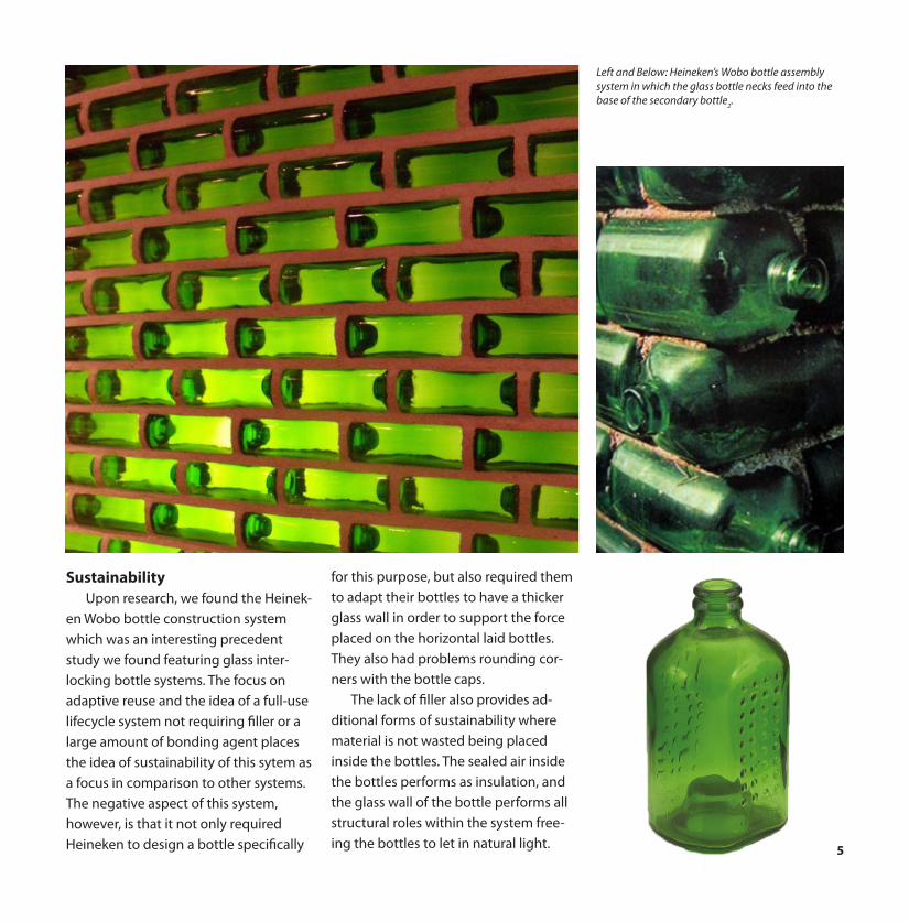
Left and Below: Heineken’s Wobo bottle assembly system in which the glass bottle necks feed into the base of the secondary bottle
2.
SustainabilityUpon research, we found the Heinek-
en Wobo bottle construction system which was an interesting precedent study we found featuring glass inter-locking bottle systems. The focus on adaptive reuse and the idea of a full-use lifecycle system not requiring filler or a large amount of bonding agent places the idea of sustainability of this sytem as a focus in comparison to other systems. The negative aspect of this system, however, is that it not only required Heineken to design a bottle specifically
for this purpose, but also required them to adapt their bottles to have a thicker glass wall in order to support the force placed on the horizontal laid bottles. They also had problems rounding cor-ners with the bottle caps.
The lack of filler also provides ad-ditional forms of sustainability where material is not wasted being placed inside the bottles. The sealed air inside the bottles performs as insulation, and the glass wall of the bottle performs all structural roles within the system free-ing the bottles to let in natural light.


7
Left: Plastic bottles are utilized in Nigeria in building both a full-scale wall and half-scale wall - even supporting a window opening
1.
Configuration and ExpressionThe use of plastic bottles, though
seemingly straight forward, can be utilized in a wide array of shapes, sizes, and configurations. The house built in Nigeria (seen on the left) expresses the true versitility of plastic bottle construc-tion. The bottles in this home are utilized as the primary structural system and are even able to support the window open-ing in the full-height curved wall.
The linear extrusion of the bottle allows for manipulation in curvature of walls and variance from the traditional square home form. These bottles, filled with sand, additionally provide protec-tion from fire and bullets
1.
After finishing construction of the bottle structural wall, it is possible to place a finish coat of plaster or adobe to cover the wall. In our research, many in-dividuals chose to leave a portion of the bottle wall exposed to provide visibility of their unique construction method and additionally provide areas of natural lighting and decoration in contrast to a singular colored wall plane. In many circumstances a full coat of plaster was also applied to completely cover any ev-idence of plastic bottles utilized within the construction phase of the building. This plaster allows the buildings to be painted and individualized as if gypsum wall board was to have been utilized in
Top: Adobe plaster is used to cover the wall of the plastic bottles (left) and wine bottles (right). The endcaps of the bottles are left exposed to provide exposure of the structure and decoration
1.
Bottom: Plastic bottles can be utilized in a variety of shapes, dimensions, and configurations as in this aquaduct by Inspiration Green
1.
the construction phase.Varrying forms can be created, as
previously discussed, with the use of plastic bottles. Arches, curved walls, straight planes, and abstract forms can be generated with the manipulation of how the bottle is laid and the variance generated by hand filling and placing the bonding agent.

Project Description
(1). Sorting of the bottles and cleaning out the bottles. Wall systems were constructed with similar bottle shapes/sizes.
(2). The bottles were filled to the top with either the shredded straw or sand in order to test the compres-sive strength of each respective filler.
(3). Wall assembliy was constructed utilizing the different mortar mixes and assembly system.
(4). Testing of the wall assemblies for their compres-sive strength relative to the other.
Testing Properties To begin testing the properties of
the plastic bottle construction systems, we first clarified which properties we wanted to test:
1. Filler2. Bonding Agent3. Wall System
We wanted to understand how the plastic bottle construction system operated as a sub-element of a larger construction methodology. This meant understanding how the forces within the system worked (if the bottle held any structural load) and which combi-nation of bottle filler - if any - and which bonding agent worked best to optimize the system both in a cost analysis and a structural analysis of the system.
The resulting testing system we utilzied was a construction and testing methodology in which involved nu-merous steps to accurately understand how the plastic bottle walls worked and how we could optimize the system. The steps to construct these systems were: (1) sort through and clean recycled plastic bottles courtesy of KU Recycling, (2) fill the bottles with their respective test filler [sand or shredded straw], (3) construct the respective wall assembly system, and (4) test the systems for their compressive strength.

9
Wall Assemblies After determining the four steps of
our testing method, we had to find wall assembly systems which would allow us to examine the different components we were examining (filler, bonding agent, and wall system). In order to test all three components we examined, it was essential to generate wall assem-blies and systems which would specifi-cally test each case.
The Single Bottle Sample was a sin-gle bottle surrounded by the bonding agent, allowing us to test the effective strength of the bonding agent itself [Fig-ure (1)]. All of the single bottle samples were all filled with straw to allow a small amount of compressive support yet consistency among results.
The Wall Block system featured a mold into which bottles were stacked and the forms filled with the clay mix [Figure (2)]. This wall block system allowed us to test the assembly strength of the block system in addition to the strength of the filler.
The Wall Composition sample was a small scale composition of the larger wall system. [Figure (3)] This assembly is most like the precedent studies we found and tested a small scale version of the compressive stresses put on a system implemented in a construction system.
Seen on the right are our original sketches of each system coupled with the constructed system.
Single Bottle Sample
Wall Block
Wall Composition
Figure (1)
Figure (2)
Figure (3)

Filler Compression Testing To begin our testing we utilized
plain, empty plastic Gatorade bottles filled with the two differing types of filler we would be testing: sand and compact-ed straw. The ideology behind filling the bottles with a material was to provide an additional level of thermal massing to improve insulation in addition to provid-ing additional structural support for the wall assembly system.
We first filled one individual Gato-rade bottle with white sand and one bottle with compacted straw. The bottles were then loaded onto the tray of the compressor and aligned with a steel plate to evenly distribute the compressive load throughout the bottle and prevent the load being applied as a singular point load voiding the compres-sive strength of the bottle as an element of the wall assembly system.
The result, to no surprise, was that the sand as a filler performed signifi-cantly better to resist compressive force applied to the bottle over the com-pacted straw as seen in Table (1). The difference, however, was the weight of each bottle. The bottle filled with sand was significantly heavier than the one filled with compacted straw.
Because of the sand filled bottle’s strong resistance to compressive force, we decided to utilize the sand filled
Right: Compression tests show the strength of the fill-er material and the deflection each material allowed within the same bottle.
The stress compression machine was used to crush the bottles to determine their maximum load before failure.
The steel plate placed above the bottles allowed the compressive load to be evenly distributed across the surface area of the plastic bottle.

11
bottles for the remaining research of our project.
The interesting values calculated and shown in Table (1) display that both bot-tles held a significant amount of weight. The straw filled bottle compressed until the steel plate pressed down upon the neck of the bottle - preventing com-pression of the entire bottle any further and distorting the load of the bottle. The sand filled bottle featured a similar property where the steel plate began to compress upon the neck of the bottle.
Both bottles exhibit an extreme amount of deflection, as seen in the im-age to the left. Though the sand bottle fell subject to a higher compressive load, the bottle deflected less than the straw bottle due to the lack of air inside of the bottle and therefore was able to spring back into a closer version of its original form.
The bottles were additionally tested in both the horizontal and vertical ori-entation to develop a concise numerical value to the strength relative to the orientation of the bottle. As shown in Table (1), it is clear that bottles laid in the horizontal axis structurally sup-port a greater amount of compressive strength. From this test on, all bottles were laid in the horizontal axis.
Straw being compacted into the plastic bottles in order to test the compressive value of straw vs. sand as bottle filler.
Bottle compressive tests were performed on bottles in both the vertical and horizontal direction.
Left: Compressive elastic and plastic failure points for the bottles filled with sand or straw in the horizontal and vertical orientation.
Bottle Filler Load (lbs) Thermal Values3 (BTU/Ft) Orientation
Sand 5,000 0.1156 Horizontal
Straw 5600 0.052 Horizontal
Straw 90 0.052 Vertical
Table (1)
3. http://www.engineeringtoolbox.com/ther-mal-conductivity-d_429.html

Bonding Mix Testing The first element we tested was the
mixes which would serve as our initial bonding agent. The compositions of those mixes were:
Right: Slump tests were performed to determine the viscosity of the clay mixture to be used as a bonding agent within the bottle wall system.
Mix 11 Water1 Clay2 Sand1 Straw
Mix 21 Water1 Clay3 Sand
Mix 31 Water1.5 Clay2 Sand

13
Mix 4.75 Water1 Clay1.75 Sand
Mix 5Concrete
Assembly Process To construct the single block assem-
bly system to test the bonding agent of the assembly we constructed formwork which bound the assembly in the the 4”x4”x8” block. The bottles were insert-ed into the formwork and surrounded with the bonding agent mix. The blocks gave us a uniform block allowing us to comparitively analyze the strength of each mix through filling all bottles with a sand filler mix.
Left: Construction of the single bottle sample with the use of plywood formwork held together by clamps.

Single Bottle Sample TestingIn order to test our various methods
and mixes we utilized a compression tester at the School of Architecture’s East Hills warehouse and the Engineering Departments concrete compression tester. The single bottle samples made primarily with a clay mixture were able to be tested at the warehouse while the wall blocks and concrete single bottle samples required the use of a larger compression tester. To successfully test the compressive strength of each Single Bottle Sample a layer of foam was placed in between the steel plate and the clay form which allows for a more uniform load when combined with the steel plate.
After testing all five mixes, we found that the blocks held two different load points - elastic failure and plastic failure. The elastic failure marked the initial fail-ure load on the blocks where the plastic load marked the secondary failure point and the final load value.
Part of the question regarding com-pressive stress was whether or not the bottles carried the load or if the bonding material that carried the load. Figure (4) shows the force through the wall assem-bly traveling around the bottle within the wall assembly. This represents the force within the wall assembly traveling solely through the bonding agent and avoiding the bottles within the wall. Figure (5) shows the bottles carrying a portion of the force within the wall assembly. Our initial hypothesis, since
Above: Table (2) shows the mixes (shown on the prior pages) held an elastic failure point (initial failure) and a plastic failure point (final failure point) shown in both total compressive strength and PSI.
Below: The question of where the florce was located in the wall assembly arose in our initial studies. Figure (4) shows the force around the bottle, where figure (5) shows the force traveling through the bottle.
Figure (4) Figure (5)
Table (2)
force takes the path of greatest resis-tance, was that the plastic bottles would carry a portion, if not all, of the force placed upon the wall system.
When testing the initial clay and singular concrete block it was unclear with our data as to which path the force placed on the wall assembly system took through the wall. We did, however, notice that Mix 5 (concrete) held a signif-
icanly higher level of force - 32 times more for PSI. Because of this significant amount of strength, we determined that it was best to incorporate concrete into the clay mixture allowing for improved strength as well as cheaper costs in com-parison to a pure concrete wall.
This new mix, called Mix 6, featured 1 part water, 1 part clay, 2 parts sand, and one-half part concrete and was

15
Mix 61 Water1 Clay2 Sand1/2 Concrete
utilized from this point of research on to optimize the clay wall’s performance against a pure concrete built assembly wall system.
In an attempt to clarifiy which path the force took through the wall assem-bly, we constructed a concrete single block (the same mix as Mix 5) in which the bottle was not filled with any filler and left void. This allowed us to compare the compression force results of the two blocks with the same bonding agent and bottles that held different filler agents: sand and void. As shown by the results in Table (3), it was clear that hav-ing the bottled filled with a substance that was able to support additional compressive load would allow the wall assembly to support increased levels of compressive stress over an assembly without filled bottles.
Above: Mix 6 was the finalized mix that combined the clay mixes for economy and concrete mix for improved strength.
Right: Stress compression on a single bottle sample to failure of the clay block.

Left: Force from the compressive strength of the con-crete block burst the side of the plastic bottle open.
Above: After removing the plastic bottle post failure, the bottled had cracked under the pressure of the sand and concrete supporting the compressive force.
Left: The concrete single bottle form being compres-sion tested at the University of Kansas Engineering Concrete Testing Lab. The sand helps to take a portion of the compressive force.

17
Table (3)
As seen in the Table (3) and the images to the left in comparison to the image on the right, the bottle contain-ing sand (left) holds a larger amount of compressive load before failing when compared to the bottle that has a void in the center (right).
The sand filled bottle burst during the compressive strength and began pouring the sand from inside of the bot-tle into the space which the bottle pre-viously occupied. This explosion began to show stress and cracks in the concrete yet the sand carried stress through the block supporting an additional 69 PSI over the empty bottle.
The empty bottle completely flattened and blew at the base of the bottle, in comparison to the sand filled bottle which blew on the side due to the compressive strength of the sand and the deflection.
This comparison between the empty bottle and sand filled bottle confirmed our conclusion that the bottle carries structural load due to the filled bottle block being able to support the addi-tional 69 PSI over the empty bottle.
Lower Right: The empty bottle within the concrete block was completely crushed flat by the compressive forced placed upon the block.
Right: Table (3) shows the compression failure values of the empty bottle concrete block in comparison to the sand filled bottle concrete block.


19
After removing the clay portion falling off of Mix 1, it was clear that though the bottle carries some struc-tural load, load still travels along the bottle edge.
The straw within Mix 1 gave the block additional strength by bonding the portions of clay together even after failure.
Concrete blocks cure around the empty plastic bottle and sand filled bottle within the 4”x4”x8” wood formwork.
The concrete block with the sand filled plastic bottle pushes plates of concrete away from the bottle as the sand pours out of the bottle.
The compressive load of the sand filled bottle concrete block was strong enough to break the concrete block which it was raised on. This proves that the strength of the sand-filled con-crete block is well above the necessary amount to structurally support a struc-ture and compressive load placed upon a wall system constructed with plastic bottles and concrete.
Left: Force from the compressive strength of the sand-filled plastic bottle concrete block broke the concrete base it was placed on.
Below: Compressive force pushing down on the singular blocks pushes on the horizontal axis of the blocks.

Wall Blocks The wall block system was testing
the ideology of constructing blocks built out of mortar and stacked platic bottles. These wall bricks would be stacked in a similar manner to the typical brick con-struction system.
These wall blocks additionally allowed us to test the strength of the straw filled bottles against the sand filled bottes within the assembly system. Although the singular bottle tests previously performed demonstrated the increased structural performance of the sand bottle system in contrast to the straw bottle system, we wanted to be sure they would perform the same with-in the full assembly context and deter-mine if the increased weight of the sand bottles would have an impact in the structural performance when integrated within the clay mix.
Similarly to the single bottle form-work, a formwork was constructed which would allow us to construct the wall blocks with a three bottle base and two bottles placed on top of the three base bottles and an additional level of three bottles as a cap.
In order to successfully distribute the compressive load across the entire top surface of the block without generating a point load at the uneven top surface of the wall block, a concrete cap was poured in an effort to level out the top of the blocks.
Looking at the data from the indi-divual bottle blocks, it was expected that the sand filled bottle block would
Above: Construction process of the wall blocks in which the bottles were completely encased in the Mix 5 clay mix. The first three bottle layer is put into place before more clay mix is added on top of the bottles.
Left: Diagram of the construction of the wall blocks.
Page 22: Wall block composed of straw filled bottles.
Page 23: Wall block composed of sand filled bottles.

21
perform better than the block with the bottles filled with straw.
Upon compression of the blocks it was found that the wall blocks followed the trend of the singular bottles in the fact that the sand filled bottles were able to support a higher compressive load than the bottles filled with straw.
During the compression of the straw bottles, once the clay casing began to fall apart the bottles immediately began to all fall, causing the block to fail.
In contrast to the immediate failure of the straw block and bottles, the block constructed with sand filled bottles was able to hold its form for additional compressive force after the clay casing had fallen off exposing the bottles - seen in the picture on page 23. This additional compressive force resistance allowed the block constructed with sand filled bottles to resist an additional 350 pounds.
Left: Table (4) shows the compression failure values of the wall block systems in comparison of the straw bottles and the sand bottles.
Table (4)
Bottom: Wall block composed of straw filled bottles is being compressed to failure point.


23

Wall Compositions The wall compositions are the
culmination in testing the plastic bottle wall assembly construction system. This small wall composition is meant to represent and recreate a large wall system in a scale small enough to test the compressive strength with.
The compositions were constructed by first laying a layer of the bonding agent (clay mix #5 or cement) on a piece of plywood, then placing a three bottle base down, surrounding them with the bonding agent, placing another layer of two bottles, and topping them off with a coat of the bonding agent.
The wall composition test sought to answer our final question that had arisen throughout our research so far: which is stronger, a clay system with sand bottles or a concrete system with empty bottles. Because of this, the clay system featured plastic bottles filled with sand while the concrete system featured empty bottles placed inside of concrete.
To no surprise, the concrete wall - de-spite having no bottle filler for structural support - vastly outperformed against the clay wall. Supporting nearly 14.5 times more compressive force, the con-crete wall was able to structurally hold not only its own weight despite the void where the bottles were located but the
Right: Table (5) shows the compression points of failure for the concrete and sand filled clay wall composition.
Table (5)
Right: Diagram of the construction of the wall composition system. This construction simulates the small scale construction of the large wall system.
Bottom: Images of the construction of the wall com-positions featuring three bottles as the base with two bottles on the secondary layer.

25
additional compressive force. The cracking within the clay wall
system seemed to appear to follow the curves of the bottles and travels straight down from the bottle to the bottom of the wall assembly (see picture to the left). In contrast to the clay system, the cracking within the concrete system linked one bottle cap to the next bottle cap instead of following along the curves of the plastic bottles. This style of cracking, which we deem panneling, is displayed by the ‘fin’ of the concrete wall being pushed up into the air off of the wall assembly from the tensile force applied to the wall edge from the point of the compressive force.
The ability of the concrete wall to support additional load without the use of filler material inside of the plastic bottles opens the opportunity for the bottles to be removed after the concrete is poured to open up the wall system for natural ventilation, natural lighting, etc. to be incorporated into the design pro-cess over just the plastic bottles required to support the wall as in the clay system.
Top: Compressive testing on the clay wall system showing cracks surrounding the bottles.
Bottom: Compressive testing on the concrete wall system showing the panneling of the concrete along bottle lines.


27


29

Wall Cost Analysis
Concrete1 bag = 777.6 in3Cost = $.93/bagCost/in3 = $0.0037/in3
Sand1 bag = 864 in3Cost = $3.77/bagCost/in3 = $0.0043/in3
Clay1 bag = 1583.13 in3Cost = $17.67Cost/in3 = $0.011/in3
Concrete Wall Cost$320.75
Mix 6 Wall Cost$409.07
λ = cost/in3 (dependent on materialP=1156 bottles in the wallV=36in3 (volume of bottle)(L x H x D) – (P x V) = θ(θ x λ) = total cost of system
As part of our findings we calculated the total cost to build a wall out of Mix 6 and out of Concrete. In order to find this value we calculated the volume of the wall minus the volume the plastic bottles would take up. Next we multiplied the volume of the wall by the cost per in3. This gave the total cost for a 10’ by 10’ by 8.91” wall. As you can see above the concrete wall was cheaper than the mix 6 wall by $88.32. Because of this we made the recomendation that concrete be used because: 1. its cheaper than mix 6 and 2. because it offers more structural stability.

31
Project Conclusion
Conclusions Our tests revealed valuable informa-
tion that can be taken and expanded upon in the future. We tested various mixtures of clay, sand, water and straw with cement as a stabilizer in some mixtures and pure concrete. These tests demonstrated that the concrete was far superior in its compressive strength as a bonding agent for the bottles being nearly fifteen times stronger in compres-sion than any of the clay mortar mixes.
The concrete in our test samples reached 767 PSI while the clay mortar mixes only reached a value of 26 PSI. In addition to the concrete being stronger, it was found that the cost of building a wall out of the clay mix would be more expensive than using concrete.
Additionally, a finish coat of adobe would not be required to protect the wall system with concrete and would require less up-keep when compared to the clay alternative.
The concrete also provides sufficient strength alone, in the application of affordable housing, for empty bottles to be used to allow natural lighting and natural ventilation through holes in the wall. This is one of the key benefits of using concrete as the bonding agent.
It was also proved that while the structural properties of the filler material was important and did hold an impact,
by using the concrete bonding agent filler material inside of the bottles was not required due to the structural integ-rity of the concrete material. Looking at the insulation values, it is also clear that the straw holds a better insulation value over sand if a filler material was to be utilized as insulation. This thermal value does not, however, take into account the properties of thermal massing which would allow the sand filled bottles to hold a significant advantage over the straw compacted plastic bottles.
Structurally the sand filled bottles performed the best with all of the mixes and tests closely followed by the straw bottles and then the empty bottles. Over the course of testing the sand bottles against the straw bottles with any mix of the bonding agent, the sand bottles were able to support 53% of the total load in comparison to the straw only supporting 47%. While this number may seem insignificant, it is important to note the total load value of 51,050 lbs - making the 6% difference a value of 3,063 lbs, see Figure (6).
After testing the value of the sand bottle , we determined that the best method of testing the value of the structural filler would be to compare the values of the best structural filler and clay with concrete and empty bottles. Between the two tests held which placed a clay mixture against a concrete mixture, the concrete supported 96% of the total load in a stark contrast to only the 4% held by the clay with a total load value of 33,246 lbs. This means the con-
crete held a total of 31,900 lbs compared to the clay assembly’s 1,346 lbs - see Figure (7).
The eventual failure of the concrete wall assembly system at 7,350 lbs far ex-ceeds the compressive force applied to the system, and the failure point for the single bottle assembly at 767.2 PSI again far exceeds any small-scale residential application in which this method of construction is intended.
The cost analysis, when added with the other outstanding conclusions made of the concrete wall systems, provides sufficient support to elect the integra-tion of a concrete wall system within a project. When analyzing our 10’x10’ wall assembly, we found that the construc-tion of the concrete wall in contrast to the clay wall allowed for a 14% reduc-tion in price of the materials for the wall system - see FIgure (8).
In conclusion of our research, we were able to answer our initial questions posed within the Executive Summary of this research document:
- Which bonding agent is best? - Which filler is best? - Do the bottles support the
load? - Can the bottles be removed?Through the process we were able
to conlude that the best bonding agent would be concrete. This conclusion was drawn from the fact that concrete was able to, as seen in Figure (7), support the most structural compressive load for construction purposes while being

Above: Linear consumerist process and adaptive reuse / recycling process. The adaptive reuse process is shown through our bottle wall system and the posi-tive attributes of the system.
Mined from Earth Manufactured Sold in Box Store Purchased Thrown Away
Adaptive Reuse + Recycling
Adaptive Reuse
Recycled
Economic system of construction
Utilizes recycling
Increased compressive force
Sustainable practice
Encourages community

33
cost efficient for a low-cost housing or constructino application [Figure (8)].
We additionally determined that the best filler agent to utilize within a clay system would be sand [Figure (6)], however, due to our choice to utilize concrete as the bonding agent, filling agent was not necessary even though it was determined that the bottles do support a structural load due to the ability of the bottles with filling agent being able to support additional weight over bottles without any filling agent - see Figure (9). Due to the high strength
of the concrete, however, it was de-termined that the additional strength gained by having a filling agent within this concrete system is not necessary for low-cost, low-rise construction for which this system is intended to be integrated with.
Because of the lack of necessity for the bottles to support a structural load, the bottles could be removed from the wall to allow for additional opportu-nities to integrate natural ventilation, windows, natural lighting, etc.
Figure (6): Breakdown of the structural strength of sand v. straw filler agents.
Figure (7): Breakdown of the structural strength of clay v. concrete as the bonding agent of the wall assembly system.
Figure (8): Breakdown of the cost to construct a 10’x10’ wall assembly system out of the Mix 6 mixture v. a completely concrete wall system.
Figure (9): Breakdown of the structural strength of a sand filled bottle in concrete v. a void bottle in concrete.
Figure (8)
Figure (6) Figure (7) Figure (9)
4%47% 53% 96% 53% 47%
43%
57%
Concrete
Mix 6 (Clay)

Bibliography
“BOTTLE BRICKS AND THE AESTHETICS OF SUSTAINABILITY.” Academia.edu. Accessed November 1, 2014. http://www.aca-demia.edu/3685038/BOTTLE_BRICKS_AND_THE_AESTHETICS_OF_SUSTAINABILITY.
“Bulletproof & Fireproof House Made From Used Plastic Bottles.” Off Grid World. Accessed November 1, 2014. http://www.offgridworld.com/bulletproof-fireproof-house-made-from-used-plastic-bottles/.
“HEINEKEN WOBO: A Beer Bottle That Doubles as a Brick.” Inhabitat Sustainable Design Innovation Eco Architecture Green Building HEINEKEN WOBO A Beer Bottle That Doubles as a Brick Comments. Accessed November 3, 2014. http://inhabitat.com/heineken-wobo-the-brick-that-holds-beer/.
“Plastic Bottle Schools.” Plastic Bottle Schools. Accessed November 3, 2014. http://www.inspirationgreen.com/plastic-bot-tle-schools.html.
“Plastics, Common Wastes & Materials.” EPA. Accessed November 3, 2014. http://www.epa.gov/osw/conserve/materials/plas-tics.htm#markets.
“RECYCLING FACTS.” Interesting Plastic Recycling Facts. Accessed November 1, 2014. http://www.mrcpolymers.com/Plasti-cRecyclingFacts.php.
Accessed November 5, 2014. http://www.quikrete.com/PDFs/DATA_SHEET-Concrete Mix 1101.pdf.
“Thermal Conductivity of Some Common Materials and Gases.” Thermal Conductivity of Some Common Materials and Gases. Accessed December 6, 2014. http://www.engineeringtoolbox.com/thermal-conductivity-d_429.html.

35

Studio 409 - Gore - Fall 2014
Chad Hemmerling
Culin Thompson
Jacob Pfeifer
SPACES OF HOPE © Spaces of Hope, Inc. 2014