addendum no - sawpa
TRANSCRIPT

SANTA ANA WATERSHED PROJECT AUTHORITY
INLAND EMPIRE BRINE LINE REACH V REHABILITATION AND IMPROVEMENT PROJECT – PHASE 1
ADDENDUM NO.2
The following addendum is being issued for the above referenced contract(s). Bidders are required to incorporate the information contained herein as if originally issued and included with the contract documents. Pursuant to Section 6 of the Bid Form, Bidders are required to acknowledge receipt of this addendum and confirm all associated impacts from this addendum are included in the Bid. Failure to acknowledge this addendum in the Bid Form will render the Bid non-responsive and will not be considered.
PRE-BID MEETING
The sign-in sheet and minutes from the Pre-Bid Meeting, held September 18, 2014, are attached.
PART 1: RESPONSES TO QUESTIONS
Questions received during the Pre-Bid Meeting are included in the attached meeting minutes.
1. A question was received during the pre-bid meeting regarding availability of required encroachment permits that was deferred to this addendum. The encroachment permits are not available during the bidding process. Costs for required permits are included in the bid schedule.The Contractor must pull the encroachment permit from appropriate jurisdictional agency. County of Riverside and City of Corona standard details for trenching, backfill, and repaving are included in the Contract Documents, Drawings D-4 and D-5.
The following are questions on Specification Section 15121 received from Steve Leffler, SEKISUI SPR, dated Thursday September 25, 2014:
2. Q - 1.01.D. – The use of the product shall not result in the formation or production of any detrimental compounds or by-products at any wastewater treatment plant. Question – is this intended to target styrene? A –No, the requirement is not intended to target styrene.
3. Q - 1.03.D. … all applicable … eternal hydrostatic groundwater pressure to the surface, whether groundwater is present or not, … This seems to contradict the design parameters in 2.05 Design Parameters A. Is the surcharge load a transient load? Can we get this apparent conflict resolved? A – There is no conflict. 1.03.D says all “applicable” surcharge loads. The design parameters govern the liner design for this project.
4. Q - 1.04.A. Greenbook – Can the reference to ASTM F1216 ‘and/or’ Greenbook be changed to ‘or’? A – The use of “and/or” allows for compliance with either standard.
1

5. A - 1.04.B Reference to ASTM-D3681; Can it be eliminated as it is not called out in the body of the specs? A – This is addressed in Part 2 of this addendum.
6. Q - 1.06.D. 10,000 hour third party 50-year Flexural and Tensile Creep Data. Can this be simplified to ‘Creep data’? A –This is addressed in Part 2 of this addendum.
7. Q - 1.06.J.3. Submit a letter of acceptance from the liner manufacturer and installer indicating acceptance of the temperature sensor cable system for use on the Project – We have never used or evaluated the temperature sensor, and I would not feel it appropriate to write the letter of acceptance. I have two problems with the cable sensor specified; 1) it has not been recognized through an ASTM standard for either an acceptable technology, or any other acceptance/use criteria, limits, dependability resolution; accuracy and precision, calibration, or any of a number of feasibility issues in pressure pipe, and 2) the thickness of the cable may introduce a ‘global’ hoop defect in the reinforcement, degrading the structural pressure capability of the liner, based upon the hoop stress equation and possibly introducing a bending moment into the hoop. A – Comment noted.
8. Q - 2.02.J. The nominal fabric tube wall thickness shall be constructed, as a minimum, to the nearest 0.5mm increment rounded up from the design thickness. This tends to be specific to a nominal needled felt. Some products, such as glass and products with a thick polymer coating do not build in 0.5mm increments. For example, a glass reinforcement product is a nominal 1.3mm thick. Another example is the polymer coating on the coated felt is nominal 0.8mm and the felts are incremented to different structural thickness increments. Please revise this to allow for the rounded up to the nearest highest incremental thickness to fit the liner manufactures product. A – This is addressed in Part 2 of this addendum.
9. Q - 2.05.A. DESIGN PARAMETERS – Groundwater Depth Above the Pipe listed as -2ft, in other words, as I read it, it puts the groundwater at the invert of the pipe – This is in apparent conflict with 1.03.D, that calls for the liner to withstand all surcharge loads, including the groundwater to the surface. Please reconcile the conflict. A – Refer to response to Question #3.
10. Q - 2.05.A DESIGN PARAMETERS – Retention Factor for Long-term Flexural Modulus. This is in apparent conflict with 1.06.D calling for us to use the creep data. Please reconcile. A – There is no conflict. 1.06.D calls for using retention valves in the specification (provided herein).
11. Q - 2.05.A. DESIGN PARAMETERS- Retention Factor for long-term tensile strength; This is low and will bump the liner into a 2-glass liner in Bypass Reach #1. Ask to change this to 50% creep retention. A – Comment noted.
2

12. Q - 2.05.B. The ASTM Tensile strength per D3039 is not a referenced standard. Change this to ASTM D-638 which is referenced. A –This is addressed in Part 2 of this addendum.
13. Q - 3.03.C Requiring a 15psi water pressure for inversion and curing is high. Likely it will be at or near the MAX cold head, and it will exceed the Max Hot head. They state that care should be taken to not cause damage to the liner, but their specifications require a level of pressure to be risky. Allow the contractor and liner manufacture to set the installation and cure head. The 15 psi will mean a tower/water column of 36ft. The tower will have to be higher. A – This is addressed in Part 2 of this addendum.
14. Q - 3.03.D.1. the spec calls for temperature monitoring system manufactured by ZIA Systems, VeriCure. This is not covered by any industry standard and I believe it may cause structural defect in a fiber reinforced pressure CIPP liner. Remove or qualify the use only if okayed by the liner manufacturer. A – Comment noted.
15. Q - 3.08.C.3. I oppose cutting and then repairing a sample removed from the installed liner. We don’t have a general repair method that effectively restores the glass overlap integrity. May have to have a ‘LinkPipe’ type of short liner used. A –Comment noted.
16. Q - 3.08.E Chemical Resistance – providing proof of Greenbook chemical resistance is possibly inconsistent with the ‘and/or’ in 1.04.A. Require ASTM F1216 chemical resistance results. A – This is addressed in Part 2 of this addendum.
The following are questions from Terry Henry, Insituform, datedMonday September 29, 2014:
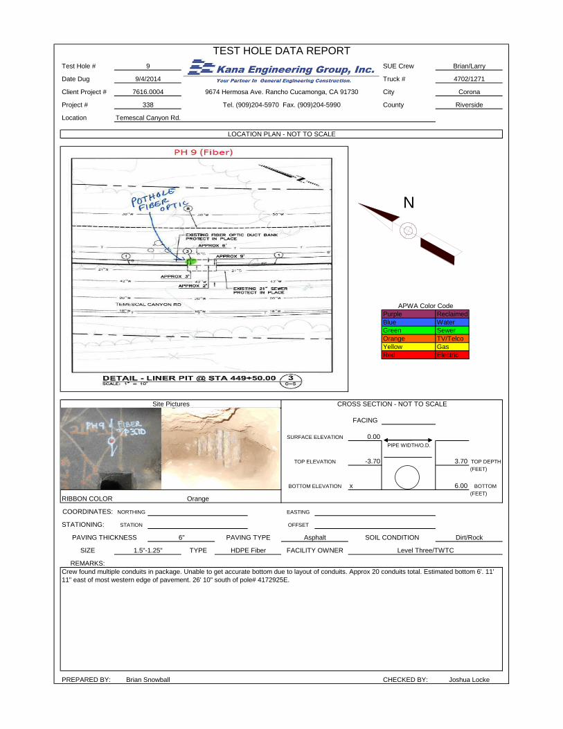
17. .Q - The Authority stated pothole excavations were performed to evaluate the PVC pipe geometry and define the project’s station limits. It was declared at the pre-bid, there are four pits that produced host pipe dimensions within this project’s start/completion stationing for this Phase 1 project that offer insight to the PVC distortion >5%. This is significant information to share with bidders to offer data supporting the CIPP lining length of the project. The stationing, ovality measurements and the calculated ovalities are requested for these four locations. A – Test pit data is attached per Part 4 of this addendum.
18. Q - It was stated by the Authority at the pre-bid that if the PVC host pipe distortion between the Authority defined pit stations contains calculated ovality greater than 5%, the entire length between the two Authority defined pit stations would be lined using CIPP. The actual required length of the distorted PVC pipe was not defined. Can you offer language stipulating this information? A - A pipe segment between pits will be lined if any ovality greater than 5% is detected.
19. Q - Is there a required calibration practice for host pipe laser profiling measurement data acquisition that must be performed prior to inspections?
3

A – Calibration should be in accordance with the laser profiling equipment manufacturer’s recommendations.
20. Q - The permissible working hours are not on the drawings as stated in the specifications. It was stated each encroachment would determine the daily work hours. Can these times for allowable access be defined prior to bidding so the number of working days can be estimated? A - The work hours are in the Traffic Control Work Hours Restrictions table on Dwg G-2.
21. Q - The design criteria of the three CIPP tubes have a common 13.5 millimeter wall thickness. The wall thickness dimension is determined by an external loading design based upon groundwater, soil and live loads. We respectfully request that internal pressure pipes: 60-psi and 30-psi internal pressure contain reinforcement to provide the required tensile properties to resist short- and long-term loadings. PVC and HDPE are not reinforced pressure pipes, but these are resilient thermoplastics. Thermoset materials; such as CIPP or Hobas, use reinforcing materials for internal pressure applications. We request your consideration for using fiber reinforcement in all internal pressure applications exceeding 10 psi of internal pressure. A - The internal pressure threshold for reinforced CIPP has been changed to 20 psi per Part 2 of this addendum.
22. Q - CIPP wall thickness is defined by the external loading and a host pipe ovality of 7%. This geometry will be used for bidding. What is the consequence of documenting lower (5 or 6%) ovality or greater (>7%) out of roundness when the laser profiling data is reviewed? If lower ovality exists or if the out of roundness is greater than the specified 7% what material should be installed and how can the contractor define the material cost for a representative bid? A - Measured ovality will not change the CIPP wall thickness design. The intention is to install the same liner thickness throughout.
23. Q - The CIPP installation is to be performed using a hydrostatic head of 15 psi. Contract documents require a 13.5 millimeter in-place CIPP wall thickness. Installing a greater wet out tube “nominal” wall thickness is intuitively required. There is no data for the contractor to select the “nominal tube thickness” for bidding and material pricing that will produce the required wall thickness when installed at approximately twice the industry’s installation pressure. The specified installation head exceeds the safe maximum internal pressure for the curing head of a tube of that diameter and thickness. This head could jeopardize the unrestrained portions of the tube approaching and within the pits causing tube rupture during the cure phase of the installation. We respectfully suggest the means and methods installation head of 15 psi be removed from the specification. The use of such an installation pressure (half or one fourth the operating internal pressures) will neither re-round the PVC pipe with the curing temperatures (180 degrees Fahrenheit curing water temperature and approaching 140 degrees at the PVC pipe CIPP tuber interface temperature) as stated during the pre-bid discussion nor allow for industry standard material utilization for this project. The CIPP materials will be designed to accommodate an out of roundness (7% in the specifications) and the structural performance will suffice without any rounding or attempt of rounding the PVC host pipe. A - The inversion pressure requirement has been modified per Part 2 of this addendum.
4

24. Q - If the specified installation head is mandated, the thickness 13.5 millimeter with a tolerance of +/- 0.5 millimeter will make the selection of the installed tube conservatively thick. A plus thickness requirement indicates the range of tolerance (1.0 mm) will not allow for CIPP wall thickness values exceeding 14.0 mm. This installation procedure and relatively narrow tolerance may be commercially impractical for CIPP installations. A - The inversion pressure requirement has been modified per Part 2 of this addendum.
25. Q - Sampling for this project is mandated as one restrained and one flat plate sample. Restraining 24” samples, although contrary to ASTM F1216, within pits is possible since access through a manhole ring is not necessary. Samples retrieved at the Owner’s discretion for removing a sample at a designated location other than the pits, generates additional cost. Is it anticipated this requirement will be invoked on each installation or only as a quality assurance measure if planned samples produce deficient or noncompliant test results? A - It would only be invoked if test results are noncompliant or an issue is suspected.
26. Q - Standard (Non-reinforced) CIPP has a tendency to crack and shrink when installed into PVC. Also, standard CIPP is not used above 10 psi, having the contractors choose between the two will give a disadvantage to a contractor who will installs a non-reinforced CIPP and will put the agency at risk for future failure. We request the internal pressure CIPP be reinforced in order to provide a common material for bidding ensuring the customer obtains the appropriate internal pressure pipe product for short and long-term performance. A - This has been addressed in Part 2 of this addendum.
PART 2: REVISIONS TO SPECIFICATIONS
27. Specification Front End Documents, pages 19-21 (Bid Schedule), shall be replaced with the attached, pages 19-21 (Bid Schedule).
28. Specification Front End Documents, Invitation to Bid, Page 5, 4th Paragraph, shall be revised to read as follows: “The Work shall be fully completed in all respects within four hundred (400) calendar days from the effective date identified in the Notice to Award.”
29. Specification Front End Documents, Agreement, Page 38, Section 3.1, 1st Sentence shall be revised to read as follows: “Contract Times: Contractor shall achieve Construction Completion within four hundred (400) calendar days from the commencement date stated in the Notice of Award.”
30. Specification Section 01010, 1.01.C.2, Page 1, shall be revised to read as follows: “Construction of below-grade maintenance access structure (MAS) assemblies along the existing 24-inch PVC pipe in accordance with the Approved Plans and the various details therein, which include Type B MAS structures with a nominal 24-inch man-way tee, 24-inch plug valve, 14-inch flow diversion connection, and connections to the existing pipe and Type A MAS structures with a nominal 24-inch man-way tee, and connections to the existing pipe.”
5

31. Specification Section 01010, 1.05.A.8, Page 4, 2nd Sentence shall be revised to read as follows: “Within two (2) working days of receiving the CCTV and laser profiling inspection results for a given segment (approximately 1,500 linear feet of pipeline length), the Owner and Construction Manager will provide the Contractor with direction on whether the subject segment (or half thereof for a length of approximately 750 linear feet) will require CIPP lining.
32. Specification Section 01010, 1.06.A.9, Page 6, delete the words “or non-reinforced”. 33. Specification Section 01010, 1.06.A.36, Page 6, delete the words “fiberglass reinforced or”.
34. Specification Section 15121, 1.04.B, Page 3, delete reference to ASTM D3681.
35. Specification Section 15121, 1.06.D, Page 4, 2nd Sentence shall be revised to read as follows:
“Submittal shall include all available Flexural and Tensile Creep test data.
36. Specification Section 15121, 1.06.J.2, Page 5, 1st Sentence shall be revised to read as follows: “The Manufacturer’s cure schedule, including the range of recommended curing pressures for each liner type to be installed.”
37. Specification Section 15121, 2.02.J, Page 7, 1st Sentence shall be revised to read as follows: “The nominal fabric tube wall thickness shall be constructed, as a minimum, to the nearest incremental thickness of the liner manufacturer’s product, rounded up from the design thickness.”
38. Specification Section 15121, 2.05.A, Pages 7-8, Table shall be replaced with the following:
Parameter Reach No. 1
Reach No. 2 BetweenSta472+00and 427+00 Only
Caltrans Reach and Reach No. 2 Except Between Sta 472+00 and
427+00 Reach No. 3 Liner Type Reinforced Reinforced Non-reinforced Non-reinforced Design Condition Fully deteriorated
host pipe Fully deteriorated
host pipe Fully deteriorated
host pipe Fully deteriorated
host pipe Design Safety Factor 2.0 2.0 2.0 2.0 Internal Pressure 60 psi 30 psi 20 psi 0 psi Ovality 7% 7% 7% 7% Groundwater Depth Above Pipe
-2 feet -2 feet -2 feet -2 feet
Soil Depth Above Pipe Crown
18 feet 18 feet 18 feet 18 feet
Live Load H20 Highway H20 Highway H20 Highway H20 Highway Soil Density 120 pounds per
cubic foot 120 pounds per
cubic foot 120 pounds per
cubic foot 120 pounds per
cubic foot
6

Parameter Reach No. 1
Reach No. 2 BetweenSta472+00and 427+00 Only
Caltrans Reach and Reach No. 2 Except Between Sta 472+00 and
427+00 Reach No. 3 Soil Modulus 750 psi 750 psi 750 psi 750 psi Minimum CIPP Wall Thickness (After Curing)
13.5 mm 13.5 mm 13.5 mm 13.5 mm
Retention Factor for Long-Term Flexural Modulus
50% 50% 50% 50%
Retention Factor for Long-Term Tensile Strength
33% 33% 33% 33%
39. Specification Section 15121, 2.05.B, Page 8, 1st Sentence shall be revised to read as follows: “The required structural CIPP minimum wall thickness after curing shall be as defined on the construction drawings, or 13.5 millimeters, as reviewed and approved by the Owner.”
40. Specification Section 15121, 2.05.B, Page 8, Test Method for Tensile Strength shall be changed to “ASTM D638”.
41. Specification Section 15121, 3.03.C, Page 10, replace the words “15 psi” with “the required pressure” in two places.
42. Specification Section 15121, 3.03.D, Page 11, 1st Sentence shall be revised to read as
follows: “Curing shall be accomplished by using hot water at the highest pressure recommended by the liner manufacturer for the liner to be installed, plus or minus 0.5 psi.”
43. Specification Section 15121, 3.8.E, Page 14, 1st Sentence shall be revised to read as follows:
“The CIPP system installed shall meet the chemical resistance requirements of Greenbook and/or ASTM F1216.”
PART 3: REVISIONS TO DRAWINGS
1. The following drawings shall be replaced with the attached revised drawings, indicating drawing revision 1 with a triangle.
a. G-1 b. C-5 c. C-18 d. D-3
PART 4: SUPPLEMENTAL REPORTS
1. Potholing report is attached.
2. Test pit report is attached.
7


Pre-Bid Conference Sign-in Sheet


Pre-Bid Conference Minutes

M E E T I N G S U M M A R Y
Santa Ana Watershed Project Authority Inland Empire Brine Line
Reach V Rehabilitation and Improvement Project – Phase 1
PRE-BID CONFERENCE
September 18, 2014
Attendees Representing Steven Mitchell Kana Engineering Jeff Garcia Professional Pipe Services Jason Bent Utah Pacific Abraham Nageeh Michels Corporation Butch King Charles King Co. Mike Bollinger Mladen Buntich Construction Kristian Corona E. J. Meyer Michael Corcoran E. J. Meyer Paul Lanhardt Pure Effect Environmental Michael Negri Sunbelt Rentals Terry Henry Insituform Technologies Rick Baxter Insituform Technologies Matt Sherwood Insituform Technologies Steve Himle WEKA Inc. Abdou Ceydi Spiniello Leo Calvario SAK Construction Amanda Combs Dudek Kate Palmer Dudek David Ruhl SAWPA Rich Haller SAWPA Carlos Quintero SAWPA Regina Patterson SAWPA
Introductions The Pre-Bid Conference for the Inland Empire Brine Line Reach V Rehabilitation and Improvement Project – Phase 1 commenced at 10:02 a.m. at the Santa Ana Watershed Project Authority located at 11615 Sterling Avenue, Riverside, California. Introductions were made.
SAWPA and Brine Line Overview - SAWPA Program Manager David Ruhl provided a brief overview of SAWPA and the Brine Line System and its purpose. Reach V Overview – David described Reach V of the Brine Line displaying the project location area. He stated Reach V is 22 miles in length with pipe ranging in size from 24” to 30” of PVC and HDPE. Project Overview – The project, located within and adjacent to the right-of-way of Temescal Canyon Road in the City of Corona and in various unincorporated areas of the county of Riverside, will be divided into four bypass reaches.
K:\BRINE LINE\PROJECTS\REACH 5 REHABILITATION\BID PROCESS\ADDENDUM 2\PRE-BID MTG SUMMARY 9-18-14.DOC 1

Project Background – Investigation following an October 2011 catastrophic failure discovered poor compaction and over-deflection of the pipe. General Description of Work – The project involves installation of 23,000 lf of CIPP, 19 Maintenance Access Structures (MAS), inspection of 27,000 lf of existing 24-inch pipe, and temporary bypassing of brine flows. Contract Documents - Contract Documents are available for purchase or download from SAWPA.org. General Engineering Contractor’s License Class A is required. California Prevailing Wages or Federal Davis Bacon Wage Rates, whichever is higher, shall apply to the project. A Bid Security of 10% of the total bid amount will be due (Certified or Cashier’s Check, or Bid Bond). Bidder schedule must be complete with base bid and additive bid items or the bid will be rejected. The low bid will based on the total of the base bid and additivie bid items. The bid sheet also includes specialty contractor work for items like CIPP. Liquidated damages are for not meeting the Brine Line shutdown periods and construction completion date. Due to the project receiving Clean Water State Revolving Funds, there are DBE requirements on this project. You will be required to conduct outreach that demonstrates a good faith effort to ensure opportunities for DBEs to compete. Entities can no longer self-certify so they must be certified at the Bid Opening. Contractor References and Qualifications (see page 35 of specs) – Three references for projects are needed to be completed by the bidder in which the bidder has installed fiberglass reinforced CIPP liner similar to that proposed for this project. The specialty contractor for CIPP installation is required to submit a statement of qualifications with the bid. Name and resume of superintendent required. Kate Palmer of Dudek identified the project components. Shutdown will only be for three days. Existing appurtenances (a combination of air valves and blow-offs) will need to be reconnected, reinstated or replaced. The project will add access to the existing pipeline through the MASs and installing the CIPP liner pits where the pipe needs to be lined. On the Bid Schedule, the MASs that are directly in line with existing pipeline are their own bid items for Type A and Type B. There are also bid items for Type A and Type B MASs that need to be offset from the existing pipeline because of existing utilities. Amanda Combs of Dudek identified the CIPP considerations. There is a single thickness required of 13.5 mm whether the liner is reinforced or not. There are areas where pressure reinforced liner is required and other areas of no pressure where we can use a non-reinforced liner. Resin requirements are vinyl ester or epoxy and curing is required to be hot water only. Regarding the inversion design considerations, the as-builts of the existing pipeline will show how the vertical profile of the pipe changes over the alignment. There is only a 3-day window to shut the Brine Line down and complete the bypass which requires MASs on either side of the bypass connections. There is a minimum amount of dewatering that will be required to get the bypass in place. The remaining dewatering to completely drain the line for the inspection and lining operations will happen once the bypass is in operation and the brine line is back in service.
K:\BRINE LINE\PROJECTS\REACH 5 REHABILITATION\BID PROCESS\ADDENDUM 2\PRE-BID MTG SUMMARY 9-18-14.DOC 2

The entire alignment will be inspected, CCTV’d and laser profiled but only the segments that are CIPP lined will have a post CCTV inspection. Kate said a large component of the project is managing the brine flow. Coordination with the owner will be imperative. The bypass operation can run by gravity. The specifications allow for a pump system but the information has to be submitted on what is intended. A suggested sequencing method is provided in Specification Section 01010. The contractor will be responsible for conducting its own potholing and verifying all existing utilities in the project area. The contractor is responsible for surveying and materials testing. The traffic control plans are currently being updated and will be included as part of an upcoming Addenda. The revisions are mainly to signage. Construction management and inspection services are being performed by Vali Cooper and Associates. Dudek provided clarification that work for each of the four bypass reaches is required to be done separately and is required to be completed before work moves to the next by-pass reach. Work within the City of Corona is not allowed between Thanksgiving Day and New Years Day. Questions are due by close of business on October 2, 2014. Bids are due on October 8, 2014 at 2:00 p.m. at the SAWPA offices. Bids will remain valid for 90 days from the Bid Opening. Questions Q – SAWPA has only two days to notify the contractor to proceed with lining on an approved reach after CCTV and laser profiling data is complete? A – Yes. Once CCTV and laser profiling data is complete and received from the Contractor, SAWPA will have 2 days to notify the Contractor to proceed or not to proceed with lining a particular segment. Q – Are the DBE requirements equivalent to the SBE requirements? The rules are changing. SBE encompasses all. A - There is explanation on contacting the Small Business Administration and working through them to obtain a list of certified MWE/WBEs. Appendix D includes the DBE requirements. Q – Who is responsible for the encroachment permits? Does the contractor incur all costs? A – The contractor is responsible for the costs and for pulling the permits. There is a bid allowance on the bid sheet. Q – Regarding laser profiling, companies have been contacted and none have the laser profiling capability. Does SAWPA have a list of companies it could recommend? A – Dudek has contacted two companies that have the capability, Pro-Pipe and Ace Pipe Cleaning.
K:\BRINE LINE\PROJECTS\REACH 5 REHABILITATION\BID PROCESS\ADDENDUM 2\PRE-BID MTG SUMMARY 9-18-14.DOC 3
Q – What are the work hours? A – The works hours will be per the encroachment permits for each agency, city and county. See Drawing No. G-2 for the Traffic Conrol Work Hour Restrictions Table Q - Will there be copies of the encroachment permits as they are currently written? How is it addressed in the bid if we don’t have the encroachment permit or a copy of the application? A – Dudek said this question will be addressed in Addendum No. 2. Q - Regarding bid items 14 and 15 of the CIPP portion of work, there is an actual footage, however, this is basically a find and fix project. Where did the footages come from? How is it bid not knowing how much pipe lining is necessary? A – The quantities (footage) in the base bid are one half of the potential footages quantities to be lined. The additive bid items are for the other half of the potential lining footages. If quantities are adjusted more than a certain percentage off of the base bid then the method for adjusting unit prices is outlined in the specifications. Q – If all of it (pipeline) is lasered, and it’s below that percentage, it’s almost impossible to provide a number for linear foot. A – There was a pipe failure on Temescal Canyon Road at Cabot Road. The ovality was greater than 5% at that location. As a follow-up to the pipe failure, we constructed test pits to measure ovality and measure soil compaction at nine (9) locations within the project boundaries (27,000 feet) Five of Nine locations had an ovality of greater than 5%. Relative compaction measured was between 69% and 83%. Q - In sequencing you ask for laser profile data and clean the pipe two days to give it to you and two days to respond, what’s the agency’s ideal time to start lining? A – The owner has two days to approve a segment for lining once the CCTV and laser profiling data is received by the owner. When the Contractor lines a segment that has been approved is up to the Contractor. Q – It takes 3-4 weeks to manufacture a liner. A - Once a by-pass reach is set-up the Contractor will be cleaning the pipeline, performing CCTV Inspection and laser profiling and installing the intermediate Type-A and Type-B MASs. While a liner is being manufactured the Contractor has the ability to perform other work as long as the Contractor meets the agency, city or county requirements, such as recessed plates for open excavations. CIPP considerations include all pipe segments to be lined are about 750 feet in length. The minimum liner thickness is 13.5 mm. Q - Can that be addressed in the addendum? A - We will review and if necessary address in an Addendum. Q - Corona will not allow work from Thanksgiving until New Years? A – Yes, the City of Corona does not allow any work during that time period. Q – Will the working days for the contract take into account the manufacturing? Will that blow the schedule? A – Yes it takes into account the manufacturing of the liner.
K:\BRINE LINE\PROJECTS\REACH 5 REHABILITATION\BID PROCESS\ADDENDUM 2\PRE-BID MTG SUMMARY 9-18-14.DOC 4

Q – You have three different designs, 60, 30 and a gravity design. Are you comfortable with non-reinforced liner being used with and internal pressure of 30 psi? A – Yes. We will review and if a clarification is necessary we will address in an Addendum. Q – What if the manufacturer is not? A – That is up to the contractor. Q - You have a mandated installation pressure and then you are checking wall thicknesses, are you comfortable with the installation pressure? A –We will review this question and if a clarification is necessary we will address in an Addendum. The 13.5 mm is the installed minimum thickness. The test method for wall thickness compliance is described in the specifications. There is an allowed tolerance. Q - You are telling us what to start with and what it has to be. A – We only state the finished thickness must be 13.5 mm. It is up to the liner manufacturer to determine what the starting thickness needs to be so that the finished thickness is 13.5 mm. Q - Installed pressure requested is twice the pressure we would install. A - We will review this question and if a clarification is necessary we will address in an Addendum. Q – If there is a spill do you have to wash down the area and return the water to the pipeline. A – If there is a spill you have to capture any standing brine and return to the Brine Line at a SAWPA approved location. Any soil that is wet will have to be removed and disposed of at an approved facility. Contractor Insurance requirements include pollution liability. Dudek provided clarification on the liner design. One of the product submittals for CIPP is liner design calculations using the actual physical properties of the liner, as long as they are substantiated by independent lab testing. .. 13.5 mils is the minimum installed thickness and should be used for the bid. 13.5 mm is based on conservative design values and we do not expect a thicker liner will be required. The meeting ended at 11:02 a.m.
K:\BRINE LINE\PROJECTS\REACH 5 REHABILITATION\BID PROCESS\ADDENDUM 2\PRE-BID MTG SUMMARY 9-18-14.DOC 5

Revised Bid Schedule

Santa Ana Watershed Project Authority Addendum No. 2 Brine Line Reach V Rehabilitation & Improvement Project – Phase 1 19
8. SALES AND USE TAXES. 8.1. The Bidder agrees that all federal, state, and local sales and use taxes are included in
the stated Bid prices for the Work. 9. BASE BID 9.1. Unit Price Work: Bidder further proposes to accept as full payment for the Unit Price Work proposed
herein the amounts computed under the provisions of the Contract Documents and based on the following unit price amounts, it being expressly understood that the unit prices are independent of the exact quantities involved. Bidder agrees that the unit prices represent a true measure of the labor, materials, and services required to furnish and install the item, including all allowances for overhead and profit for each type and unit of Work called for in these Contract Documents.
Item Description1
Quantity Unit Unit Price Extended
Total Amount
1. Mobilization and Demobilization (not to exceed 5 % of total bid price.)
1 LS $ $
2. State Required Line Item for Labor Code Section 6705 and 6707 – Trench Excavation Plan and Sheeting, Shoring, and Bracing Including all Labor, Equipment, and Materials
1 LS $ $
3. Water Pollution Control Plan 1 LS $ $
4. Flow Bypass 1-3 (Outside of Caltrans Right-of-Way)
1 LS $ $
5. Flow Bypass in Caltrans Right-of-Way
1 LS $ $
6. Drain Brine as Required for Cleaning and Inspection
1 LS $ $
7. Cleaning of 24” PVC Pipe 26,100 LF $ $
8. Traffic Control 1 LS $ $
9.
(S)
High Definition CCTV Inspection with Laser Profiling of 24” PVC Pipe Along Entire Project Alignment
26,100 LF $ $

Santa Ana Watershed Project Authority Addendum No. 2 Brine Line Reach V Rehabilitation & Improvement Project – Phase 1 20
Item Description1
Quantity Unit Unit Price Extended
Total Amount
10. Maintenance Access Structure A Assembly, Including Potholing
9 EA $ $
11. Maintenance Access Structure B Assembly, Including Potholing
6 EA $ $
12. Offset Maintenance Access Structure A Assembly Perpendicular to Brine Line Pipe, Including Potholing
2 EA $ $
13. Offset Maintenance Access Structure B Assembly Perpendicular to Brine Line Pipe, Including Potholing
2 EA $ $
14.
(S)
Fiberglass CIPP Liner for 24” PVC Pipe, Including Post-Installation CCTV, and Pressure Testing
7,918 LF $ $
15.
(S)
Non-Reinforced CIPP Liner for 24” PVC Pipe, Including Post-Installation CCTV, and Pressure Testing
3,600 LF $ $
16.
(S)
CIPP Liner Installation Pit with End Seals and Pipe, Including Potholing
17 EA $ $
17. Disconnect and Reinstatement of 4” Air/Vacuum Valve Assembly, Including New Valve (along pipe segments that are CIPP lined)
14 EA $ $
18. New 4” Air/Vacuum Valve Assembly, Including New Valve (along pipe segments that are not CIPP lined)
3 EA $ $
19. Disconnect and Reinstatement of 8” Blow-off Assembly (along pipe segments that are CIPP lined)
15 EA $ $
20. Disconnect and Reinstatement of Existing 8” Blow-off Assembly (along pipe segments that are not CIPP lined)
3 EA $ $
21. Abandonment of Existing Inline Valve Prior to CIPP Lining
1 EA $ $

Santa Ana Watershed Project Authority Addendum No. 2 Brine Line Reach V Rehabilitation & Improvement Project – Phase 1 21
Item Description1
Quantity Unit Unit Price Extended
Total Amount
22. Record Drawings 1 LS $ $
23. Materials Testing 1 LS $ $
24. Owner-Directed Demobilization and Remobilization
1 EA $ $
25. Permit Fee Allowance 1 LS $ 50,000 $ 50,000
26. Field Order Allowance 1 LS $ 75,000 $ 75,000
27. Test Pits from STA 221+40 to STA 108+50
3 EA $ $
ADDITIVE BID ITEMS2
28.
(S)
Fiberglass CIPP Liner for 24” PVC Pipe, Including Post-Installation CCTV, and Pressure Testing
7,918 LF $ $
29.
(S)
Non-Reinforced CIPP Liner for 24” PVC Pipe, Including Post-Installation CCTV, and Pressure Testing
3,600 LF $ $
TOTAL EXTENDED AMOUNT FOR UNIT PRICE WORK LISTED ABOVE $
1 Detailed bid descriptions included in Section 01025 2 Additive Items will be paid on a per linear foot basis as added to the contract and approved by the Owner. (S) indicates Work items considered to be Specialty Contractor Work 9.2. Base + Additive Bid Summary (Bidder Schedule shall be complete in its entirety or will be
rejected)
Sum of Bid Items 1 thru 27: $
Sum of Bid Items 28 & 29: $
Last Minute Deduction, Items 1-27 (if any): ($ )
Last Minute Deduction, Items 28-29 (if any): ($ )
Total Bid in Figures: $
Total Bid in Words:

Potholing Report

338
7616.0004
8/28/2014
9/5/2014
1 9/5/2014 Corona 2" PVC Rec. Water 0.00 -2.30 -2.50 2.30
Gas line was marked closer to proposed line, client requested to locate gas. Gas line not found.
Crew found irrigation line while digging for gas. Reclaimed water @ 2.30'. Crew continued
digging to 5' and found concrete across entire bottom of hole. 4' 4" west of east median C/F
2 8/29/2014 0 0 0 0.00 0.00 0.00 0.00
NOT FOUND - Crew dug 6' and did not find target utility. Needed to get off street due to permit
restriction of time.42' 4" south of reclaimed water valve.
3 9/3/2014 So Cal Gas 8" Steel HP Gas 0.00 -2.84 -3.56 2.84 High Pressure Gas Line. 54' 4" north of SAWPA man hole. 13' 6" east of east median C/F.
4 9/5/2014 0 8" Steel HP Gas 0.00 -4.42 -5.14 4.42
High Pressure Gas Line - Gas was marked closer to proposed line, client requested to locate gas
line. 40' West of east C/F. 50' south of D/D# 2034664E
5 9/4/2014 Level Three TWTC 0 0 0.00 0.00 0.00 0.00
NOT FOUND - Crew dug down 6.5' deep 2.5' east and west of locaters marks and did not find
target. During investigation, crew determinedthat target might be diving to get under box culvert.
22' east of west C/F. 115' south of water vlave.
6 9/3/2014 Level Three TWTC
Encasem
ent Slurry Fiber 0.00 -0.90 -2.80 0.90 Encasement9.5' east of west C/F. 21' south of water valve.
7 9/4/2014 So Cal Gas 8" Steel HP Gas 0.00 -3.32 -4.04 3.32 High Pressure Gas Line. 5' East of easter edge of pavement. 80' south of P/P# 4524599E
8 1/0/1900 0 0 0 0.00 0.00 0.00 0.00
This Gas line does not exhist. Ends 100' north or pothole location (Per Ray Rascon @ So Cal
Gas).
9 9/4/14
Level
Three/TWTC
1.5"-
1.25" HDPE Fiber 0.00 -3.70 x 3.70
Crew found multiple conduits in package. Unable to get accurate bottom due to layout of
conduits. Approx 20 conduits total. Estimated bottom 6'. 11' 11" east of most western edge of
10 8/29/2014 So Cal Gas 8" Steel HP Gas 0.00 -4.34 -5.06 4.34 Steel High Pressure Gas. 1' east of eastern edge of pavement. 50' south of P/P# 4087919E.
11 9/3/2014 Level Three TWTC
Encasem
ent Conctete/Fiber 0.00 -0.50 -3.52 0.50
Crew found slurry encasement directly under asphalt. Crew then opened pothole up to 6" west to
find edge of encasement.24' 3" east of western edge of pavement. 36' 9" south of telephone man
Top
Elevation
Bottom
Elevation
Date Complete:
Utility Owner
Utility
Description
Depth of
Cover
Utility
Size
Ground
Elevation
Testhole Data Summary
Job #:
Client Job #:
TH #
Date of
Excavation
Comments
Date Started:
9674 Hermosa Ave.
Rancho Cucamonga, CA 91730
(909) 204-5970 1

Contacts
KEG
TitlePhone #Name
Superintendent909-204-5987Brian Snowball
KEG Estimator714-412-0099Joshua Locke
Company

Test Hole # SUE Crew
Date Dug Truck #
Client Project # City
Project # County
Location
Purple Reclaimed
Blue Water
Green Sewer
Orange TV/Telco
Yellow Gas
Red Electric
FACING Cnorth
0.00 2.38
PIPE WIDTH/O.D.
-2.30 2.30 TOP DEPTH
(FEET)
-2.50 2.50 BOTTOM
RIBBON COLOR(FEET)
COORDINATES: NORTHING EASTING
STATIONING: STATION OFFSET
SIZE TYPE
REMARKS:
PREPARED BY: CHECKED BY:
Gas line was marked closer to proposed line, client requested to locate gas. Gas line not found. Crew found irrigation line while digging for gas.
Reclaimed water @ 2.30'. Crew continued digging to 5' and found concrete across entire bottom of hole. 4' 4" west of east median C/F
Brian Snowball Joshua Locke
SOIL CONDITION Compacted Dirt/Rock
2" PVC Rec. Water FACILITY OWNER Corona
PAVING THICKNESS
Blue
N/A PAVING TYPE N/A
TOP ELEVATION
BOTTOM ELEVATION
SURFACE ELEVATION
APWA Color Code
N
Site Pictures CROSS SECTION - NOT TO SCALE
338 Riverside
9674 Hermosa Ave. Rancho Cucamonga, CA 91730
Tel. (909)204-5970 Fax. (909)204-5990
Temescal Canyon Rd.
LOCATION PLAN - NOT TO SCALE
TEST HOLE DATA REPORT
1 Brian/Larry/Hermon
9/5/2014 4702/1271
7616.0004 Corona

Test Hole # SUE Crew
Date Dug Truck #
Client Project # City
Project # County
Location
Purple Reclaimed
Blue Water
Green Sewer
Orange TV/Telco
Yellow Gas
Red Electric
FACING
0.00
PIPE WIDTH/O.D.
0.00 TOP DEPTH
(FEET)
0.00 0.00 BOTTOM
RIBBON COLOR(FEET)
COORDINATES: NORTHING EASTING
STATIONING: STATION OFFSET
SIZE TYPE
REMARKS:
PREPARED BY: CHECKED BY:
FACILITY OWNER
NOT FOUND - Crew dug 6' and did not find target utility. Needed to get off street due to permit restriction of time.42' 4" south of reclaimed water
valve.
Brian Snowball Joshua Locke
PAVING THICKNESS 7" PAVING TYPE Asphalt SOIL CONDITION Base/Dirt
BOTTOM ELEVATION
TOP ELEVATION
Site Pictures CROSS SECTION - NOT TO SCALE
SURFACE ELEVATION
338 Tel. (909)204-5970 Fax. (909)204-5990 Riverside
Temescal Canyon Rd.
LOCATION PLAN - NOT TO SCALE
NOT FOUND
APWA Color Code
N
TEST HOLE DATA REPORT
2 Brian Hermon
8/29/2014 4702/1271
7616.0004 9674 Hermosa Ave. Rancho Cucamonga, CA 91730 Corona

Test Hole # SUE Crew
Date Dug Truck #
Client Project # City
Project # County
Location
Purple Reclaimed
Blue Water
Green Sewer
Orange TV/Telco
Yellow Gas
Red Electric
FACING
0.00 8.63
PIPE WIDTH/O.D.
-2.84 2.84 TOP DEPTH
(FEET)
-3.56 3.56 BOTTOM
RIBBON COLOR(FEET)
COORDINATES: NORTHING EASTING
STATIONING: STATION OFFSET
SIZE TYPE
REMARKS:
PREPARED BY: CHECKED BY:
8" Steel HP Gas FACILITY OWNER So Cal Gas
High Pressure Gas Line. 54' 4" north of SAWPA man hole. 13' 6" east of east median C/F.
Brian Snowball Joshua Locke
PAVING THICKNESS 10" PAVING TYPE Asphalt SOIL CONDITION Dirt/Rock
BOTTOM ELEVATION
Yellow
TOP ELEVATION
Site Pictures CROSS SECTION - NOT TO SCALE
SURFACE ELEVATION
338 Tel. (909)204-5970 Fax. (909)204-5990 Riverside
Temescal Canyon Rd.
LOCATION PLAN - NOT TO SCALE
N
APWA Color Code
TEST HOLE DATA REPORT
3 Brian/Hermon/Lary
9/3/2014 4702/1271
7616.0004 9674 Hermosa Ave. Rancho Cucamonga, CA 91730 Corona

Test Hole # SUE Crew
Date Dug Truck #
Client Project # City
Project # County
Location
Purple Reclaimed
Blue Water
Green Sewer
Orange TV/Telco
Yellow Gas
Red Electric
FACING North
0.00 8.63
PIPE WIDTH/O.D.
-4.42 4.42 TOP DEPTH
(FEET)
-5.14 5.14 BOTTOM
RIBBON COLOR(FEET)
COORDINATES: NORTHING EASTING
STATIONING: STATION OFFSET
SIZE TYPE
REMARKS:
PREPARED BY: CHECKED BY:
8" Steel HP Gas FACILITY OWNER
High Pressure Gas Line - Gas was marked closer to proposed line, client requested to locate gas line. 40' West of east C/F. 50' south of D/D#
2034664E
Brian Snowball Joshua Locke
PAVING THICKNESS 12" PAVING TYPE Asphalt SOIL CONDITION Dirt/Rock
BOTTOM ELEVATION
Yellow
TOP ELEVATION
Site Pictures CROSS SECTION - NOT TO SCALE
SURFACE ELEVATION
338 Tel. (909)204-5970 Fax. (909)204-5990 Riverside
Temescal Canyon Rd.
LOCATION PLAN - NOT TO SCALE
N
APWA Color Code
TEST HOLE DATA REPORT
4 Brian/Hermon
9/5/2014 4702/1271
7616.0004 9674 Hermosa Ave. Rancho Cucamonga, CA 91730 Corona

Test Hole # SUE Crew
Date Dug Truck #
Client Project # City
Project # County
Location
Purple Reclaimed
Blue Water
Green Sewer
Orange TV/Telco
Yellow Gas
Red Electric
FACING
0.00
PIPE WIDTH/O.D.
0.00 TOP DEPTH
(FEET)
0.00 0.00 BOTTOM
RIBBON COLOR(FEET)
COORDINATES: NORTHING EASTING
STATIONING: STATION OFFSET
SIZE TYPE
REMARKS:
PREPARED BY: CHECKED BY:
FACILITY OWNER Level Three TWTC
NOT FOUND - Crew dug down 6.5' deep 2.5' east and west of locaters marks and did not find target. During investigation, crew determinedthat target
might be diving to get under box culvert. 22' east of west C/F. 115' south of water vlave.
Brian Snowball Joshua Locke
PAVING THICKNESS 4" PAVING TYPE Asphalt SOIL CONDITION Rock/Sand
BOTTOM ELEVATION
TOP ELEVATION
Site Pictures CROSS SECTION - NOT TO SCALE
SURFACE ELEVATION
338 Tel. (909)204-5970 Fax. (909)204-5990 Riverside
Temescal Canyon Rd.
LOCATION PLAN - NOT TO SCALE
N
APWA Color Code
TEST HOLE DATA REPORT
5 Brian/Larry
9/4/2014 4702/1271
7616.0004 9674 Hermosa Ave. Rancho Cucamonga, CA 91730 Corona

Test Hole # SUE Crew
Date Dug Truck #
Client Project # City
Project # County
Location
Purple Reclaimed
Blue Water
Green Sewer
Orange TV/Telco
Yellow Gas
Red Electric
FACING North
0.00 24
Enc. WIDTH/O.D.
-0.90 0.90 TOP DEPTH
(FEET)
-2.80 2.80 BOTTOM
RIBBON COLOR(FEET)
COORDINATES: NORTHING EASTING
STATIONING: STATION OFFSET
SIZE TYPE
REMARKS:
PREPARED BY: CHECKED BY:
Encasement Slurry Fiber FACILITY OWNER Level Three TWTC
Encasement9.5' east of west C/F. 21' south of water valve.
Brian Snowball Joshua Locke
PAVING THICKNESS 5" PAVING TYPE Asphalt SOIL CONDITION Base
BOTTOM ELEVATION
Orange
TOP ELEVATION
Site Pictures CROSS SECTION - NOT TO SCALE
SURFACE ELEVATION
338 Tel. (909)204-5970 Fax. (909)204-5990 Riverside
Temescal Canyon Rd.
LOCATION PLAN - NOT TO SCALE
N
APWA Color Code
TEST HOLE DATA REPORT
6 Brian/Hermon/Lary
9/3/2014 4702/1271
7616.0004 9674 Hermosa Ave. Rancho Cucamonga, CA 91730 Corona

Test Hole # SUE Crew
Date Dug Truck #
Client Project # City
Project # County
Location
Purple Reclaimed
Blue Water
Green Sewer
Orange TV/Telco
Yellow Gas
Red Electric
FACING North
0.00 8.63
PIPE WIDTH/O.D.
-3.32 3.32 TOP DEPTH
(FEET)
-4.04 4.04 BOTTOM
RIBBON COLOR(FEET)
COORDINATES: NORTHING EASTING
STATIONING: STATION OFFSET
SIZE TYPE
REMARKS:
PREPARED BY: CHECKED BY:
8" Steel HP Gas FACILITY OWNER So Cal Gas
High Pressure Gas Line. 5' East of easter edge of pavement. 80' south of P/P# 4524599E
Brian Snowball Joshua Locke
PAVING THICKNESS NA PAVING TYPE NA SOIL CONDITION Compacted Dirt/Rock
BOTTOM ELEVATION
Orange Stake
TOP ELEVATION
Site Pictures CROSS SECTION - NOT TO SCALE
SURFACE ELEVATION
338 Tel. (909)204-5970 Fax. (909)204-5990 Riverside
Temescal Canyon Rd.
LOCATION PLAN - NOT TO SCALE
N
APWA Color Code
TEST HOLE DATA REPORT
7 Brian/Larry
9/4/2014 4702/1271
7616.0004 9674 Hermosa Ave. Rancho Cucamonga, CA 91730 Corona

Test Hole # SUE Crew
Date Dug Truck #
Client Project # City
Project # County
Location
Purple Reclaimed
Blue Water
Green Sewer
Orange TV/Telco
Yellow Gas
Red Electric
FACING
0.00
PIPE WIDTH/O.D.
0.00 TOP DEPTH
(FEET)
0.00 0.00 BOTTOM
RIBBON COLOR(FEET)
COORDINATES: NORTHING EASTING
STATIONING: STATION OFFSET
SIZE TYPE
REMARKS:
PREPARED BY: CHECKED BY:
FACILITY OWNER
This Gas line does not exhist. Ends 100' north or pothole location (Per Ray Rascon @ So Cal Gas).
Brian Snowball Joshua Locke
PAVING THICKNESS PAVING TYPE SOIL CONDITION
BOTTOM ELEVATION
TOP ELEVATION
Site Pictures CROSS SECTION - NOT TO SCALE
SURFACE ELEVATION
338 Tel. (909)204-5970 Fax. (909)204-5990
Temescal Canyon Rd.
LOCATION PLAN - NOT TO SCALE
N
APWA Color Code
TEST HOLE DATA REPORT
8
7616.0004 9674 Hermosa Ave. Rancho Cucamonga, CA 91730
Test Hole # SUE Crew
Date Dug Truck #
Client Project # City
Project # County
Location
Purple Reclaimed
Blue Water
Green Sewer
Orange TV/Telco
Yellow Gas
Red Electric
FACING
0.00
PIPE WIDTH/O.D.
-3.70 3.70 TOP DEPTH
(FEET)
x 6.00 BOTTOM
RIBBON COLOR(FEET)
COORDINATES: NORTHING EASTING
STATIONING: STATION OFFSET
SIZE TYPE
REMARKS:
PREPARED BY: CHECKED BY:
1.5"-1.25" HDPE Fiber FACILITY OWNER Level Three/TWTC
Crew found multiple conduits in package. Unable to get accurate bottom due to layout of conduits. Approx 20 conduits total. Estimated bottom 6'. 11'
11" east of most western edge of pavement. 26' 10" south of pole# 4172925E.
Brian Snowball Joshua Locke
PAVING THICKNESS 6" PAVING TYPE Asphalt SOIL CONDITION Dirt/Rock
BOTTOM ELEVATION
Orange
TOP ELEVATION
Site Pictures CROSS SECTION - NOT TO SCALE
SURFACE ELEVATION
338 Tel. (909)204-5970 Fax. (909)204-5990 Riverside
Temescal Canyon Rd.
LOCATION PLAN - NOT TO SCALE
N
APWA Color Code
TEST HOLE DATA REPORT
9 Brian/Larry
9/4/2014 4702/1271
7616.0004 9674 Hermosa Ave. Rancho Cucamonga, CA 91730 Corona

Test Hole # SUE Crew
Date Dug Truck #
Client Project # City
Project # County
Location
Purple Reclaimed
Blue Water
Green Sewer
Orange TV/Telco
Yellow Gas
Red Electric
FACING North
0.00 8.63
PIPE WIDTH/O.D.
-4.34 4.34 TOP DEPTH
(FEET)
-5.06 5.06 BOTTOM
RIBBON COLOR(FEET)
COORDINATES: NORTHING EASTING
STATIONING: STATION OFFSET
SIZE TYPE
REMARKS:
PREPARED BY: CHECKED BY:
8" Steel HP Gas FACILITY OWNER So Cal Gas
Steel High Pressure Gas. 1' east of eastern edge of pavement. 50' south of P/P# 4087919E.
Brian Snowball Joshua Locke
PAVING THICKNESS NA PAVING TYPE NA SOIL CONDITION Compact Dirt/Trash
BOTTOM ELEVATION
Yellow/Stake
TOP ELEVATION
Site Pictures CROSS SECTION - NOT TO SCALE
SURFACE ELEVATION
338 Tel. (909)204-5970 Fax. (909)204-5990 Riverside
Temescal Canyon Rd.
LOCATION PLAN - NOT TO SCALE
N
APWA Color Code
TEST HOLE DATA REPORT
10 Brian/Hermon
8/29/2014 4702/1271
7616.0004 9674 Hermosa Ave. Rancho Cucamonga, CA 91730 Corona

Test Hole # SUE Crew
Date Dug Truck #
Client Project # City
Project # County
Location
Purple Reclaimed
Blue Water
Green Sewer
Orange TV/Telco
Yellow Gas
Red Electric
FACING North
0.00 24
PIPE WIDTH/O.D.
-0.50 0.50 TOP DEPTH
(FEET)
-3.52 3.52 BOTTOM
RIBBON COLOR(FEET)
COORDINATES: NORTHING EASTING
STATIONING: STATION OFFSET
SIZE TYPE
REMARKS:
PREPARED BY: CHECKED BY:
Encasement Conctete/Fiber FACILITY OWNER Level Three TWTC
Crew found slurry encasement directly under asphalt. Crew then opened pothole up to 6" west to find edge of encasement.24' 3" east of western edge
of pavement. 36' 9" south of telephone man hole.
Brian Snowball Joshua Locke
PAVING THICKNESS 4" PAVING TYPE Asphalt SOIL CONDITION
BOTTOM ELEVATION
Orange
TOP ELEVATION
Site Pictures CROSS SECTION - NOT TO SCALE
SURFACE ELEVATION
338 Tel. (909)204-5970 Fax. (909)204-5990 Riverside
Temescal Canyon Rd.
LOCATION PLAN - NOT TO SCALE
N
APWA Color Code
TEST HOLE DATA REPORT
11 Brian/Hermon/Lary
9/3/2014 4702/1271
7616.0004 9674 Hermosa Ave. Rancho Cucamonga, CA 91730 Corona
Test Pit Data Tables
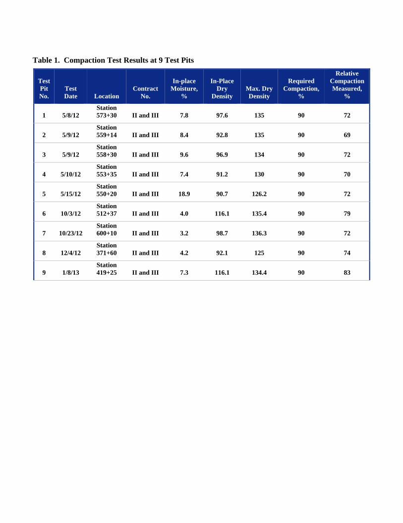
Table 1. Compaction Test Results at 9 Test Pits
Test Pit No.
Test Date Location
Contract No.
In-place Moisture,
%
In-Place Dry
Density Max. Dry Density
Required Compaction,
%
Relative Compaction Measured,
%
1 5/8/12 Station 573+30 II and III 7.8 97.6 135 90 72
2 5/9/12 Station 559+14 II and III 8.4 92.8 135 90 69
3 5/9/12 Station 558+30 II and III 9.6 96.9 134 90 72
4 5/10/12 Station 553+35 II and III 7.4 91.2 130 90 70
5 5/15/12 Station 550+20 II and III 18.9 90.7 126.2 90 72
6 10/3/12 Station 512+37 II and III 4.0 116.1 135.4 90 79
7 10/23/12 Station 600+10 II and III 3.2 98.7 136.3 90 72
8 12/4/12 Station 371+60 II and III 4.2 92.1 125 90 74
9 1/8/13 Station 419+25 II and III 7.3 116.1 134.4 90 83

Table 2. Pipe Ovality Measured at 9 Test Pits Test Pit No. Test Date Location
Contract No.
Depth to Top of Pipe
Average Measured X Dimension(1)
Average Measured Y Dimension(1) Ovality, %
1 5/8/12 Station 573+30 II and III 5’-4” 27 24.7 4.7
2 5/9/12 Station 559+14 II and III 7’-10” 27.2 24.5 5.4
3 5/9/12 Station 558+30 II and III 10’-6” 27.6 24.1 7.1
4 5/10/12 Station 553+35 II and III 7’-2” 27.3 24.4 5.6
5 5/15/12 Station 550+20 II and III 9’-0” 26.5 25.1 2.7
6 10/3/12 Station 512+37 II and III 5’-11” 27.5 24.2 6.6
7 10/23/12 Station 600+10 II and III 11’-0” 26.8 24.9 3.7
8 12/4/12 Station 371+60 II and III 6’-2” 26.8 24.9 3.7
9 1/8/13 Station 419+25 II and III 7’-3” 27.5 24.2 6.6

Revised Drawings G-1, C-5, C-18, and D-3


7616.0004INLAND EMPIRE BRINE LINE
REACH V REHABILITATION & IMPROVEMENT PROJECT
605 Third Street Encinitas, CA 92024
760.942.5147 Fax 760.632.0164
98
TEMESCAL CANYON RD
TE
ME
SC
AL C
AN
YO
N R
D
TEMESCAL C
ANYON R
D
15
C-5
8
GRAPHIC SCALE
CONSTRUCTION NOTES:

7616.0004INLAND EMPIRE BRINE LINE
REACH V REHABILITATION & IMPROVEMENT PROJECT
605 Third Street Encinitas, CA 92024
760.942.5147 Fax 760.632.0164
98
C-18
21
DETAIL - LINER PIT @ STA 464+50.00 1 DETAIL - MAS V-0470-B 2 DETAIL - LINER PIT @ STA 449+50.00 3
GRAPHIC SCALE
TEMESCAL CANYON RD
TEMESCAL CANYON RD
TEMESCAL CANYON RD
NOTES:
SECTION - MAS V-0470-B2
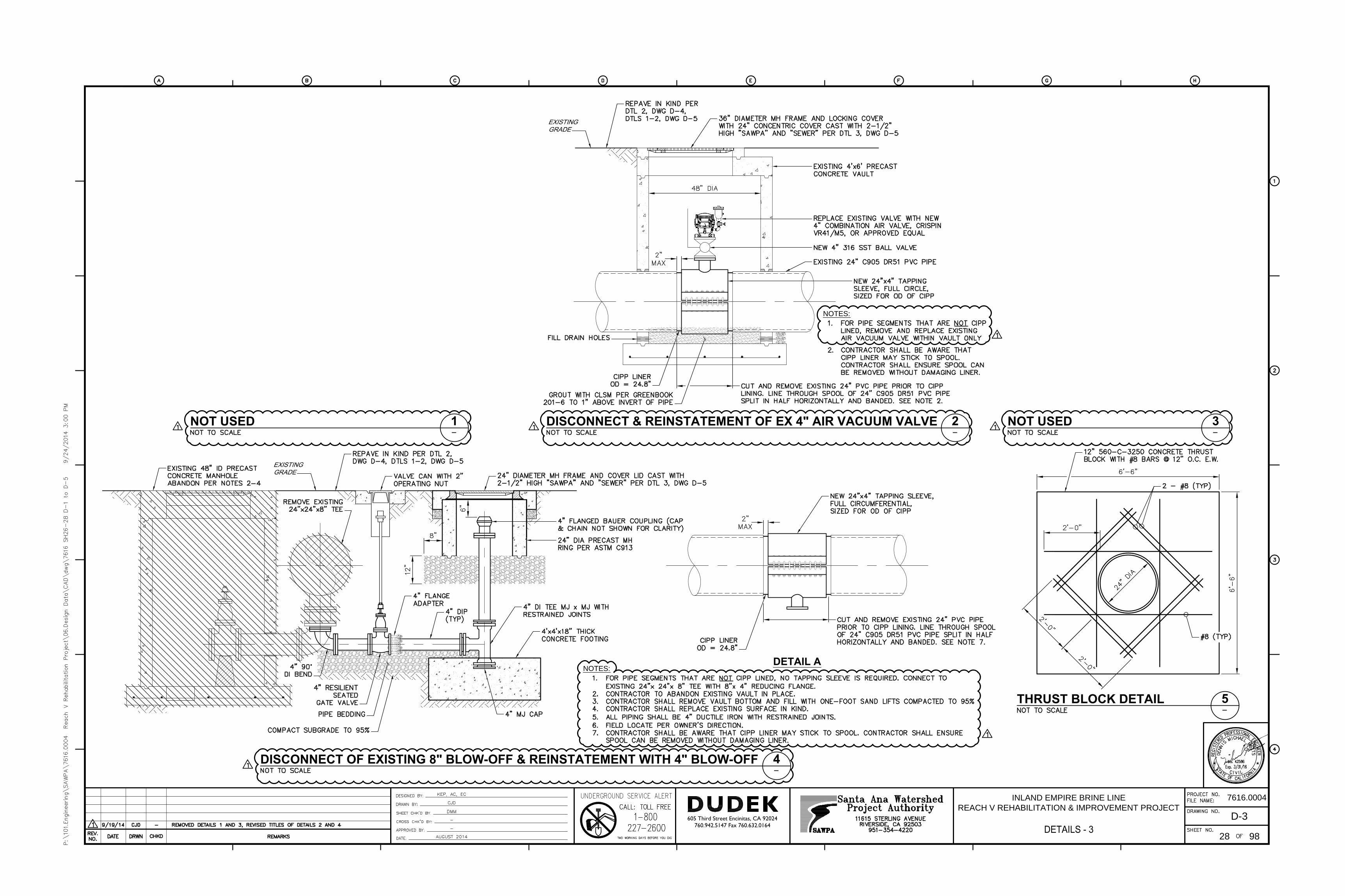
7616.0004INLAND EMPIRE BRINE LINE
REACH V REHABILITATION & IMPROVEMENT PROJECT
605 Third Street Encinitas, CA 92024
760.942.5147 Fax 760.632.0164
98
D-3
28
NOT USED 1 NOT USED 32
4
NOTES:
DETAIL A
DISCONNECT & REINSTATEMENT OF EX 4" AIR VACUUM VALVE
DISCONNECT OF EXISTING 8" BLOW-OFF & REINSTATEMENT WITH 4" BLOW-OFF
THRUST BLOCK DETAIL 5
NOTES: