additional information for engines with oil injection · recommendation: the setting for the...
TRANSCRIPT

Appendix B 0-1
16.02.05 DOC_Anhang_B_E_0.01 Page 1 of 12
Appendix B
Additional Information for Engines with Oil Injection
Attention: The chapter on Oil Injection (Appendix B) is only to be used in connection
with the service manual for the corresponding engine type. All sections of
the manual, with exception of the chapters concerning lubrication, are
from here on still fully valid. Please read all instructions before installing
the engine or its operation.
General Directions:
In order to provide for the continuing further development of our products we have to reserve
the right to make changes in the size of deliveries, in form, technical execution, and
equipment. We also ask for your understanding that no claims can be made based on
information contained in this manual.
Göbler-Hirth Engines KG, Max-Eyth-Str. 10, 71726 Benningen, Germany

Appendix B 0-1
16.02.05 DOC_Anhang_B_E_0.01 Page 2 of 12
Table of Contents:
1. Description of Oil Injection
1.1. General description of oil injection
1.2. Names and description of individual parts
2. Installation Instructions
2.1. Mechanical installation
2.2. Hydraulic installation
2.3. Installation instruction
2.4. Additional Measures to Ensure Safety of the Construction
3. Operation of the System
3.1. Operational means
3.2. First time operation
3.3. Operation of the oil injection system
4. Maintenance/Service Intervals
5. Diagram
5.1. Hydraulic diagram
6. Trouble shooting

Appendix B 0-1
16.02.05 DOC_Anhang_B_E_0.01 Page 3 of 12
1 Description of Oil Injection
1.1 General description of oil injection
An oil pump transports the two stroke oil directly from a container into the intake manifold
and in special constructions also directly to hard to reach areas to be lubricated (for example:
top bearing when vertically installed [H30; H32]).
The oil pump is fastened to the recoil starter or to a support of the fan housing and is
connected by way of the clutch directly to the crankshaft.
With the exception of the H30, H37 and the H32, the oil ratio depends on 2 variables.
1. Number of rotations
2. Throttle position (loaded condition)
The oil ratio of the H30, H37 and the H32 depends solely on the engine rpm.
1.2 Names and description of individual parts
• Oil container (sketch 5.1 pos. 5)
Function: Reservoir for the two stroke oil for the oil injection
Minimum amount of oil: F30, H30, 3701 und H37 > 2,5 Liter
All others > 1,5 Liter
1. Filling socket with air vent
2. Connection of oil line to oil pump
• Oil level indicator and/or warning light (sketch 5.1. pos. 4)
Function: Gives information about present oil level and/or warns when below
minimum level.
• Oil filter (sketch 5.1. pos. 3)
Function: Cleaning the oil from foreign parts which may damage or conjest the oil
injection system.
• Oil pump (sketch 5.1. pos. 2)
Function: To dispatch and measure out the oil for the suction sockets and the areas
to be lubricated.
The oil pump consists of the following main components:
1. Rope disc and Bowden cable holder (pict. 1)
Function: Guide for load depending regulator for the amount of oil
Note: With motors of the H-series the amount of oil will only be changed in
connection with the rotation number. Therefore, the lever has been adjusted and set
at the factory and may not be changed.
2. Oil connections (pict. 1)
Function: The connection from oil pump to motor has been factory-installed. The
open oil connector is for the connection from the oil reservoir.

Appendix B 0-1
16.02.05 DOC_Anhang_B_E_0.01 Page 4 of 12
2. Installation Instructions
The following instructions have to be adhered to for a safe and trouble free operation
2.1. Mechanical Installation (oil pump control):
• Install a "splitter" into the throttle cable for the carburettor - i.e. throttle valve control.
• Install a Bowden cable between splitter and oil pump.
• Measure and cut the end of Bowden cable and affix lead seal.
• Hang Bowden cable into guide disc.
For 2-cylinder engines:
• Open carburettor i.e. throttle valve completely and adjust the Bowden cable to the
required length (pict. 1a).
Attention: please note that the respective marks on control dial of oil pump are to
be understood only as the minimum settings requiring the final
adjustment to the desired mixture ratio.
Remarks: For engines with 2 carburettors or throttle valve sockets, the 2
carburettors, i.e. throttle valves first have to be synchronized to each
other, before adjusting the oil pump.
For 3-cylinder engines:
• keep the basic engine setting from factory or adjust the engine without load (e.g.
propeller) to idle speed 1400-1500 rpm
Stop the engine and keep position of throttle valve in idle position.
Harmonize mark on oil pump housing and line mark on sheave.
In general:
• Secure the adjusting screw with counter nut.
• Activate throttle control several times, then check the adjustment and if necessary
readjust. Repeat until the setting does not change anymore.
• Check that the Bowden cable to the oil pump action is not bent and runs smoothly.
Furthermore, assure that the Bowden cable can not be damaged by sharp edges or nearby
heat, etc.
• Check that the Bowden cable can not jump from the guide disc.
Note: The amount of oil may not be reduced by changing the setting of the guide
disc, because too lean an operation in the partial load may cause serious engine
damage. There is no way the operator can adjust the amount of oil.
2.2. Hydraulic Installation:
• The oil reservoir must be situated higher than the oil pump, since the oil pump can not
begin suction independently.
• An oil filter has to be installed between the oil reservoir and the oil pump in order to avoid
damage or clogging of the oil pump.
• All lines have to be attached in sufficient distance to hot parts (i.e. exhaust system).
• The oil lines have to be laid out in such a way, that they may not be damaged by sharp
edges.
• The oil lines must not be bent. They have to be secured in such a way that bending can not
occur even during operation.
• For safety, hose clamps must be affixed to all connections of the oil lines.

Appendix B 0-1
16.02.05 DOC_Anhang_B_E_0.01 Page 5 of 12
2.3. Installation Instruction
1. Mount the engine as described in the individual service manual.
2. Mount the oil reservoir as described in section 2.2 above.
3. Connect oil reservoir and oil pump, insert an oil filter into the line.
4. Ensure that the necessary amount of oil can flow from the oil reservoir to the oil pump.
To do this, hang the oil hose into a measuring cup at the level of the pump, fill 200 ml
2 stroke oil for the oil injection into the oil reservoir. Clock the time between the
beginning and the end of the oil flow.
5. For engines H30, F30, 3701, the 200ml must have run through a maximum of 20 min.
For engines 2702-2706 and H32 E, 30 min maximum. When measuring, the oil- and
surrounding temperature should be between 10-20°C. Should the passage take longer
than stated, the position of the oil reservoir has to be changed accordingly until the
flow condition described is reached.
6. Connect the oil hose to the entrance of the oil pump and secure with a hose clamp.
7. Fill oil reservoir with 2 stroke oil for the oil injection.
8. Vent the oil pump by opening the air vent screw (pictures 1a and 1b). Wait until the
oil exits the bore hole without bubbles. Then the vent bore hole must be closed again.

Appendix B 0-1
16.02.05 DOC_Anhang_B_E_0.01 Page 6 of 12
Picture 1a: Front view of Oil pump all engines except 3 cylinder models.
Bowden cable
Full gas mark 2706.
3203 and 3503
(minimum)
and H32 adjustment
Marking Oil pump
case
Oil exits
Air vent screw Bowden cable holder
Cab disc
Full gas mark
F23, 2704, 3202,
3502 (minimum)
Oil entrance

Appendix B 0-1
16.02.05 DOC_Anhang_B_E_0.01 Page 7 of 12
Picture 1b: Front view of oil pump (3-cylinder engines)
2.4 Additional Measures to Ensure Safety of the Construction:
The following measures are not necessary for a secure operation of the installation.
1. Install a fill level indicator into the oil reservoir to control the oil level.
2. Install a warning light when going under the minimum amount of oil.
Recommendation: The setting for the minimum amount of oil should be chosen so
as to ensure that the remaining amount of oil is sufficient for the
entire fuel tank capacity.
3. Check the used amount of oil in relationship to the used amount of fuel in order to be
able to react in time to a blocked or worn out oil pump.
Note: The consumption of oil is strongly influenced by the fuel setting. If the
engine is operated with various loads the oil consumption may vary
also.
3. Operation of the System
3.1. Operational means
Only brand name 2 stroke oils may be used. They have to be suitable for oil injection
and must be labeled accordingly.
For safe engine operation and least wear Göbler-Hirth Engines recommends
BlueMax AL 2-stroke oil.
oil entrance Oil exits
Air vent screw
Marking oil pump
case
Idle mark 3 cyl.

Appendix B 0-1
16.02.05 DOC_Anhang_B_E_0.01 Page 8 of 12
3.2. First Time Operation:
1. Fill fuel tank with at least 10 liters of pre mixed fuel (1:50).
2. Start engine and let idle.
3. Manually completely open guide disc of the oil pump (see picture 1).
4. Check that oil lines fill evenly with oil.
5. After all oil lines have filled with oil, reposition guide disc to the idle position.
6. Let engine run for another 5-10 minutes and turn off.
7. Check all oil lines for leaks and whether the oil pump setting is still correctly
adjusted.
8. Operate engine with the rest of the mixture, before refuelling.
3.3. Operation of the Oil Injection System:
See chapter 4 about maintenance and service intervals.
Before each operation it is necessary to ensure, that the oil reservoir contains a
sufficient amount of oil for the planned time of operation, since an interruption of the
oil supply may lead to serious engine damage.
Appendix B 0-1
16.02.05 DOC_Anhang_B_E_0.01 Page 9 of 12
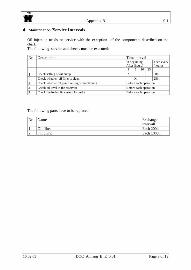
4. Maintenance-/Service Intervals
Oil injection needs no service with the exception of the components described on the
chart.
The following service and checks must be executed:
Nr. Description Timeinterval
In beginning
After (hours)
Then every
(hours)
1 5 10 25
1. Check setting of oil pump X 50h
2. Check whether oil filter is clean X 25h
3. Check whether oil pump setting is functioning Before each operation
4. Check oil level in the reservoir Before each operation
5. Check the hydraulic system for leaks Before each operation
The following parts have to be replaced:
Nr. Name Exchange
intervall
1. Oil filter Each 200h
2. Oil pump Each 1000h

Appendix B 0-1
16.02.05 DOC_Anhang_B_E_0.01 Page 11 of 12
5. Diagram 5.1. Hydraulic Diagram
1 Engine
2 Oil pump
3 Oil filter
4 Oil level gauge
5 Oil reservoir
h >=0

Appendix B 0-1
16.02.05 DOC_Anhang_B_E_0.01 Page 12 of 12
6. Trouble Shooting
Attention, should it become clear that no or too little oil is being moved, the engine must immediately be changed to a
lubrication mixture of 1:50 until the problem is solved, otherwise serious damage to the engine may occur. Problem Cause Control Elimination Insufficient oil flow Oil pump setting not properly
adjusted
See Chapter 2.1. Readjust oil pump setting
Oil filter blocked Check amount of flow (see Chapter 2.3. Pos.5) Exchange filter
Too much oil flow Oil pump setting not properly
adjusted
See Chapter 2.1 Read just pump setting
No or too small amount of
oil in one channel
Defektive injection valve Exchange injection valves and check whether or not the defect
changes too.
Replace injection valve
Oil line blocked or pinched Check oil lines visually Exchange oil line
Oil pump defective Measure amount of oil flow of all channels without injection
valve and with new lines
Exchane oil pump
No amount of oil flow Inflow stopped up, Oil filter
blocked
Check amount of flow (see Chapter 2.3. Pos.5) Exchange filter
Oil pump defective Measure amount of oil flow of all channels without injection
valve
Exchange oil pump

Oil injection tips
The oil injection pump pushes oil to the injectors but does not draw oil from the reservoir
tank. The pump is gravity feed so your choice for mounting the reservoir tank must be
high enough that the outlet on bottom of tank is at least 1” higher than the supply inlet
hose barb on the pump. In the case of a tractor prop installation the tank will be lower
during climb than in level flight so it may be necessary to mount the tank 2 or 3 inches
higher than the pump. Use ¼” hose with the supplied oil filter in between pump and tank.
Make sure the oil filter is installed with the oil flow arrow toward the pump.
This is a variable rate oil injection system meaning the RPM of the engine combined with
the position of the cable disk on the front of the pump will determine the ratio. The cable
disk must be connected to your throttle cable system so that as you increase throttle the
disk moves as well which increases the oil flow. On a tractor prop application this can
simply be a 3rd cable run all the way to your quadrant. On pusher applications the
quadrant will be much farther away from the engine and the small spring on the pump
cable disk may not be strong enough to pull the cable back when you go to idle. This is
where a 3 way throttle cable splitter can come in handy. You can purchase a cable splitter
from Aircraft Spruce. The oil injection manual shows how to initially adjust the cable. On
2 cylinder engines after cable is installed bend the retaining tab over to keep it in place.
Once installed and reservoir tank filled you need to bleed the air out of the pump. There
is a small bleed screw on the side of the pump that you turn out a few turns to bleed the
air. Once the air is gone and oil begins to come out tighten the bleed screw. There is still
air in the injection lines that can not be bled out until engine is started and until it is there
will be no lubrication. For your first run you need to premix your first tank of fuel at 50:1
ratio. This will keep engine lubricated until the oil injection system is functioning. Pull
the black plastic protective sheath that is around the oil lines back at each injector far
enough that you can see the white oil line on each. After engine is started monitor the
line. When the air is gone and oil is all the way to the injector you will be able to see it in
the line. You can shove the sheath back into place. Once the oil is flowing make a mark
on the tank that reflects the oil level. Also record how much fuel is in the fuel tank. Start
the break in procedure. Before you refill fuel tank record how much fuel you used for
break in. Refill oil tank until you are back at your mark measuring exactly how much oil
is required to refill it. Now do the math to determine what ratio of oil you are getting. As
an example if you used 8 gallons total for the break in and 14.5 ounces of oil your ratio is
70:1. - 8X128 ounces in a gallon = 1024 ounces of fuel divided by 14.5 = 70:1 oil ratio.
70: to 1 is the correct ratio. If the ratio found on the survey is substantially less than 70:1
increase the amount the cable disk on the pump is actuated by adjusting the cable adjuster
on the oil pump to increase it. If you are using too much oil adjust the cable adjuster so
that the cable disk is opened less. Keep doing short surveys (1 gallon of fuel at 5000Rpm
per survey) making adjustments until the required ratio is achieved. When you are
confident engine is receiving sufficient oil from the oil injection system (70:1) to operate
safely you can stop premixing oil with the fuel and begin running straight gas.
Size of reservoir tank: You want to choose an oil reservoir tank that will not run empty
before the fuel tank does. If your oil ratio is 70:1 a 1 gallon oil reservoir tank would

provide enough oil for 70 gallons of fuel. A 3 quart tank would cover 52 gallons, a 2
quart tank is good for 35 gallons and a 1 quart tank would be good for 17.5 gallons of
fuel. If you had a 10 gallon fuel tank a 1 quart oil tank would be more than enough oil for
each tank full but would have to be refilled each time the fuel tank is refilled. With 2
quarts of oil you could run 3 full tanks of fuel before refilling the oil tank. There are
various reasons for oil injection failures but by far the largest percentage of failure is
forgetting to refill the oil tank. For this reason some users will choose the 1 quart tank
and just get into the habit of refilling it at the some time they add fuel. Also it takes up
less room. You want to use a translucent oil tank that allows you to see the oil level at a
glance to insure you always have enough before you leave.
Recommended oil ratios: Blue Max 2 cycle injection oil – 70:1
Off the shelf mineral based 2 cycle injection oils – 60:1
Synthetic 2 cycle oils: 45:1 for pure synthetic - 50:1 for synthetic/mineral blends
Note: Hirth does not recommend the use of any type or blend of synthetic oil.
Do not use Blue Max pre mix oil in an oil injected engine.
Engines with recoil starter: On 2 cylinder in line engines the oil pump is installed on the
recoil starter. Too avoid shipping damage to the pump we sometimes remove the pump
and the oil line clamp and store it alongside the engine in a small plastic bag. Also inside
the bag are the two 5mm pump mounting bolts. Simply line up the pump driving slot with
the pump shaft, push the pump into place and install the two 5mm bolts with blue
locktight on the threads. (25 inch pounds) Note that one of the 5mm bolts is longer than
the other so be sure to install them in the correct mounting foot on the pump. Install the
oil line clamp to the recoil starter case with the spacer between the clamp and the recoil
case. Use Blue loccktight on the threads and torque to 86 inch pounds.
Re positioning the recoil handle: If you decide you want the recoil handle to exit the
engine in a different direction it is possible to pull the 3 mounting bolts out and turn the
recoil. You will first have to remove the oil pump. When re installing the recoil it is
imperative that it is centered with the crankshaft. To center the recoil install all 3 screws
(with blue locktight) until they are just snug and you can still move the recoil slightly.
Snap the recoil handle out hard until it catches but do not pull the engine over. Hold the
tension on the handle with one hand and tighten the 3 recoil mounting bolts with the
other. Now pull the handle out about a foot and let go. If the handle recoils back easily
you have the starter centered and you can go ahead and torque the 3 mounting bolts to 86
inch pounds. If the handle has drag when you let go loosen the 3 bolts and repeat the
centering procedure until the recoil is centered. If you pulled the recoil off the engine
make sure the rubber insert that goes between the pump shaft and the crankshaft is still in
the coupling and that the coupling is lined up before you push the recoil in place. If you
let the rubber insert fall out the coupling will shear off in a short time and you will have a
total failure of the lubrication system. Now that the recoil is in a new position you will
find the pump mounting holes no longer line up. Remove the pump mount plate from the
front of the recoil, turn it until the pump mount holes are again in correct position then re
install the plate mounting bolts with blue locktight 925 inch pounds) and then re mount
the pump as per pump mounting instructions previously mentioned above.

Form: 17283rev4
Fig. No No. Designation Hirth Ref. No Neoteric
No. Notes
1 1 Oil pump 045.9 5426
2 1 Cylinder screw D912M5x16 Shorter (port side) oil pump schs .Loctite 243
3 2 Locking washer 053.8/5 Belleville washer under pump mount shcs 4 1 Cable adjuster holder 3211 A3 Aluminum bracket to attach cable
5 1 Cylinder screw (Timing Adj. Hardware) D912 M5X20 Longer (starboard side) oil pump
shcs.Loctite 243 6 1 Cylinder screw D912 M6X12 2469 Holds cable adjuster in place.Loctite 243 7 1 Serrated Locking washer 053.8/6 6902 Belleville washer under DIN912M6X12 8 1 Isolating hose D40621 B5X0,6/140 7128 Short single oil line cover (black) 9 1 Isolating hose D40621 B8x0,7/330 7129 Long single oil line cover (black) 10 1 Hose 062.28/380 3425 Supply hose front 13” long 11 4 Hose Clamp (small) 5646 Clamp hose to tank & Filter 12 1 Hose 063.28/500 3425 Supply hose rear 16 ¼” long 13 1 Cable tie rap 026.40 2372 Zip tie, do not use 14 1 Cylinder Screw Din 912 M6x25 Do not use 15 2 Washer DIN 125 B6,4 6916 Do not use 16 1 Hexagon head screw DIN 985 M6 5572 Do not use 17 1 Hexagon head screw DIN 934 M6 Do not use 18 1 Washer DIN 433 6,4 Do not use 19 4 Hose clamp (smaller) 5489 Clamp hose to pump & carbs 20 1 Oil Filter 5505 Inline oil filter Arrow = Flow Direction 21 1 Splash Cover 6246 Fiberglass part, Neoteric manufactures 22 1 Adjusting Screw 6105 Oil Injection Cable Adjuster Screw 23 1 Adjusting Screw Nut 6106 Nut to lock adjuster screw 24 1 3” Hose Clamp, SS 2734 Hose clamp for splash cover
24
Arrow = Flow Direction On Filter
22
23
11
19

Fig. No Qty Designation Hirth Part No. Neoteric Part No.
Notes
1 1 Driving Dog with starter 275Y3U 6189 Dog Pulley
2 3 Cylinder Screw DIN 6912M8X35 Dog Pulley hardware, SCHS Md=23‐28Nm
3 3 Tab washer 053.8/8 Belleville washer under DIN6912M8X35
50 1 Recoil 275AF1U 5471 Pull Start
6 2 Cylinder screw DIN 912 M6X35 6911 Pull Start Hardware SCHS Md=9,6…11 Nm
7 2 Spring Ring DIN7980 6 6940 Pull Start Hardware, Belleville washer under DIN912M6X35
8 1 Cylinder screw DIN 912 M6X50 2479 Pull Start Hardware SCHS (Only applies to 5471 pull start long screw)Md=9,6…11 Nm
9 1 Spacer pipe 264 H4 6935 Pull Start Hardware
10 1 Washer DIN 125 B6,4 6916
11 1 Pipe clamp with rubber 063.24 6697 Small #8 clamp
12 1 Solenoid starter 195 A1
13 2 Cylinder screw DIN 912 M8X30 2348 Starter SCHS bolt
14 2 Spring ring DIN 127 B8 Belleville washer under DIN912M8X30
15 1 Mounting Plate 3211 A4 Round plate on front 5471
16 3 Cylinder screw DIN 912 M5X16 SCHS holds on round plate 3211A4
17 3 Serrated tab washer 053.8/5 Belleville washer under DIN912M5X16
18 2 Deep groove ball bearing DIN 625 6200 2RS/C3 6887 Located inside 5471
19 1 Shaft 3211 A5 Located inside 5471
20 1 Locking ring DIN 472 30X1,2 Located inside 5471
21 1 Coupling right 3211 A8 Located inside 5471
22 1 Coupling element 040.4/2 Rubber coupling element. Loctite 243
23 1 Coupling left 3211 A7 Aluminum coupler engine side. Loctite 243 –reverse threaded
24 1 Threaded pin DIN 913 M6X20 LH Reverse thread set screw that attaches 3122A7 to the crankshaft. Loctite 243‐reverse threaded
