advanced diagnostics for detection and root cause analysis of problems in power€¦ · ·...
TRANSCRIPT

© ABB Inc.April 19, 2011 | Slide 1
WPO-100-1A&1BAdvanced diagnostics for detection and root cause analysis of problems in power transformers
ABB Automation & Power World: April 18-21, 2011

© ABB Inc. April 19, 2011 | Slide 2
WCS-100-1A & 1B Advanced diagnostics for detection and root cause analysis of problems in power transformers
Dr. Poorvi Patel
Manager, TRES Engineering
Solutions
ABB
St. Louis, MO

© ABB Inc.April 19, 2011 | Slide 3
Your safety is important to usPlease be aware of these emergency procedures
In the event of an emergency please dial ext. 55555
from any house phone. Do not dial 9-1-1.
In the event of an alarm, please proceed carefully to the
nearest exit. Emergency exits are clearly marked
throughout the hotel and convention center.
Use the stairwells to evacuate the building and do not
attempt to use the elevators.
Hotel associates will be located throughout the public
space to assist in directing guests toward the closest exit.
Any guest requiring assistance during an evacuation
should dial “0” from any house phone and notify the
operator of their location.
Do not re-enter the building until advised by hotel
personnel or an “all clear” announcement is made.

© ABB Inc.April 19, 2011 | Slide 4
Your safety is important to usConvention Center exits in case of an emergency
Know your surroundings:
Identify the meeting room your workshop is being held in
Locate the nearest exit

Advanced diagnostics for detection and root cause analysis of problems in power transformers
What is DFR?
DFR- Cases
What is SFRA?
FRA- Cases

Why Dielectric Frequency Response?
Traditional Power Factor Testing
Power
factor
Frequency (Hz)
60 Hz1 mHz 1 kHz

Dielectric Frequency Response
50 Hz1 mHz 1 kHz
Frequency (Hz)
Power
factor

Dielectric Response of Power Transformers
Off-line diagnostics
Oil and cellulose insulation system
Dielectric properties are strongly affected by
moisture and ageing.
Dielectric response measurements can be
used for diagnostic purposes.

Why Dielectric Response
Purpose of measurement
Diagnostic test of insulation system
Moisture content
Oil Conductivity
Diagnose defects in system
Diagnose high PF or tan
Contamination
Carbon Tracking
Resistance in core ground circuit
Quality control test of Factory and/or Field processing
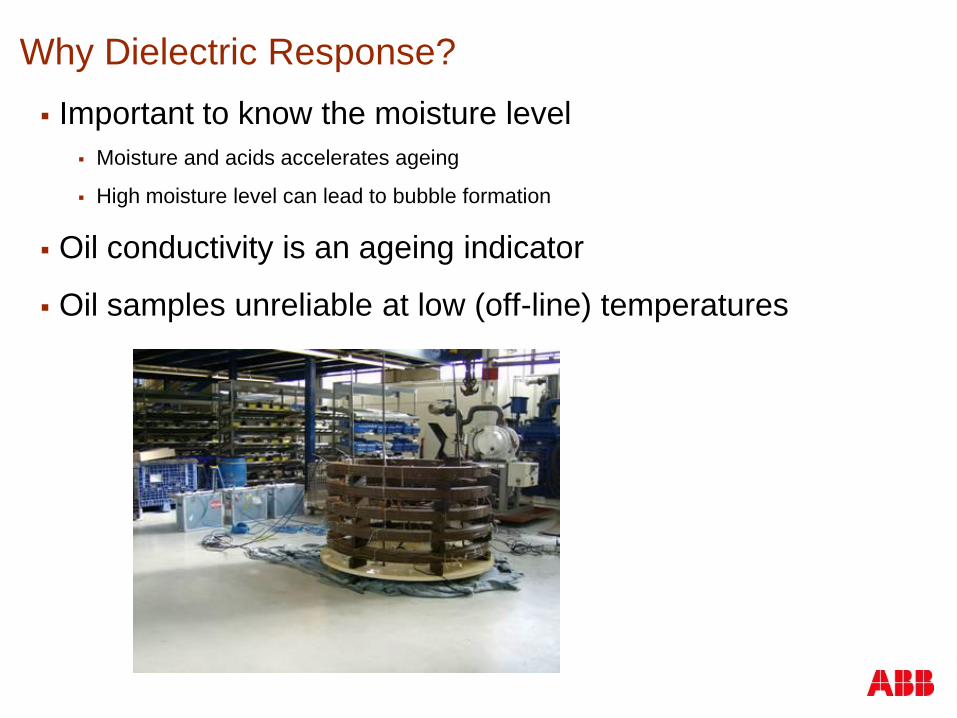
Why Dielectric Response?
Important to know the moisture level
Moisture and acids accelerates ageing
High moisture level can lead to bubble formation
Oil conductivity is an ageing indicator
Oil samples unreliable at low (off-line) temperatures

Uncertain area
Big Errors at Low Temperatures
Cellulose Moisture from Oil Samples
From. P.J.Griffin, C. M. Bruce and J. D. Christie:“Comparison of Water Equilibrium in Silicone and
Mineral Oil Transformers”, Minutes of the Fifty-Fifty Annual Conference of Double Clients, Sec.
10-9.1, 1988

Power Products where DFR is used
Transformer diagnostics
Power Transformers
Transformer Bushings
Instrument Transformers
Cable diagnostics
XLPE cables
Oil/paper cables
Manufacturing controlling system
Trouble shooting electrical apparatus
Material chacterization

DFR Measurements
DFR-Measurements

Equipment Setup
Sinusoidal signal of amplitude up to 200V peak
Frequency sweep range
0.0001 – 10 kHz maximum
.001 – 1000 Hz typical
0.01-1000 Hz minimum
Three-electrode set up: the voltage electrode
“Hi”, the current sense electrode “Lo” and the
ground
UST
(GST)
GST-g

UST Setups
Ungrounded specimen test, UST, with guard
Hi
CHL
CHCL
LoHi
Lo
Guard
Hi
Lo
Ground
U
I
G
Hi
CHL
CHCL
LoHi
Lo
Guard
Hi
Lo
Ground
U
I
G
U
I
G
DFR-Instrument
Earth connection
Hi
CHL
CHCL
LoHi
Lo
Guard
Hi
Lo
Ground
U
I
G
Hi
CHL
CHCL
LoHi
Lo
Guard
Hi
Lo
Ground
U
I
G
U
I
G
DFR-Instrument
Hi
CHL
CHCL
LoHi
Lo
Guard
Hi
Lo
Ground
U
I
G
Hi
CHL
CHCL
LoHi
CHL
CHCL
LoHi
Lo
Guard
Hi
Lo
Ground
U
I
G
Hi
CHL
CHCL
LoHi
Lo
Guard
Hi
Lo
Ground
U
I
G
U
I
G
DFR-Instrument
Earth connection

Two winding transformer
With this lead connection the following
measurement could be performed
No Mode Hi
(Red)
Lo
(Blue)
Ground
(Black)
Configuration Measure
1 UST High Low Tank UST CHL
2 GST High Low Tank GST-Guard CH

Two winding transformer
With this lead connection the following
measurement could be performed
No Mode Hi
(Red)
Lo
(Blue)
Ground
(Black)
Configuration Measure
1 GST Low High Tank GST-Guard CL
Hi
Lo
Ground
Hi
Lo
Ground

Three winding transformer

Rainy days
Instrument is sensitive to water Can cause failure of electronics if the instruments gets soaked
Keep instrument under shelter if rain threatens
Water on bushings affects readings Try guarding the bushing porcelain
UST test between windings usually
unaffected.

Minimize Influence of contaminated Bushing insulation
GST-g and GST with small low voltage bushings or
wet or dirty bushings, recommend guarding the bushing
insulation to minimize the influence of contamination
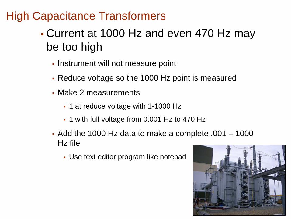
High Capacitance Transformers
Current at 1000 Hz and even 470 Hz may
be too high
Instrument will not measure point
Reduce voltage so the 1000 Hz point is measured
Make 2 measurements
1 at reduce voltage with 1-1000 Hz
1 with full voltage from 0.001 Hz to 470 Hz
Add the 1000 Hz data to make a complete .001 – 1000
Hz file
Use text editor program like notepad

Low Capacitance Measurement
Instrument may stop and display error message.
Determine the reason for the low capacitance
Check nameplate connection
Check for inner-winding shields
Change the minimum capacitance value on the C
file
Make the measurement
Look for unusual results

Noise
Noise is any signal that is not produced by the
applied voltage or the response of the transformer
AC Noise
Overhead power lines
Nearby energized transformers
Improper grounds
Harmonics
DC Noise
Ground currents
Dissimilar metals
Industrial processes

DC Noise
Problems
Causes Error Signal and Halts Test
Can cause error if DC current is large
Solution
Increase DC current limit in C file
Check Grounding Connections
Record DC current levels for future reference

Error Message – High dc current

Oil & Air Temperature
-Top and Bottom Oil Temperature
- Air Temperature

Oil Conductivity Measurement

Check the DFR- Instrument before testing
1) Red on 1, blue on 2 and black on 0 – UST – C12
2) Red on 1, blue on 2 and black on 0 – GSTg – C10
3) Red on 2, blue on 1 and black on 0 – GSTg – C20

DFR Modeling
DFR-Analysis

Dielectric Response of a Power Transformer
Dielectric response of a power transformer depends on:
The dielectric response of the constituent materials
The structure/geometry of the constituent material
Oil and Pressboard in Series
OIL BOARD

soil
Dielectric Response - Insulation Oil

Dielectric Response of Moisture Content
0.5%
2.0%
4.0%

10 ºC30 ºC50 ºC70 ºC
DR of Oil Impregnated Pressboard, Temperature Dependence

Dielectric Response of a Power Transformer
Dielectric response of a power transformer depends on:
The dielectric response of the constituent materials
The structure/geometry of the constituent material
Oil and Pressboard in Series
OIL BOARD

Measurement considerations
Winding configurations
LV HV
XV HV
HV
Reg
H0
Core
CHL => meas. D1
D2D1
HV
Reg
LV HV
XV HV
H0
Core
D1D2
CHL => meas. D1//D2

Power Transformer Insulation: Oil & Cellulose
Segment of insulation in main duct
• Cylindrical barriers
• Axial spacers
Simplified geometry for modelling:
The X-Y model
Relative proportion of barriers, X
Relative proportion of Sticks, Y
Outer windingCore
Barrier
Stick
Oil
Inner windingOuter windingCore
Barrier
Stick
Oil
Inner winding
Oil
Barrier
Stick
X
1-X
Y 1-Y
Oil
Barrier
Stick
X
1-X
Y 1-Y
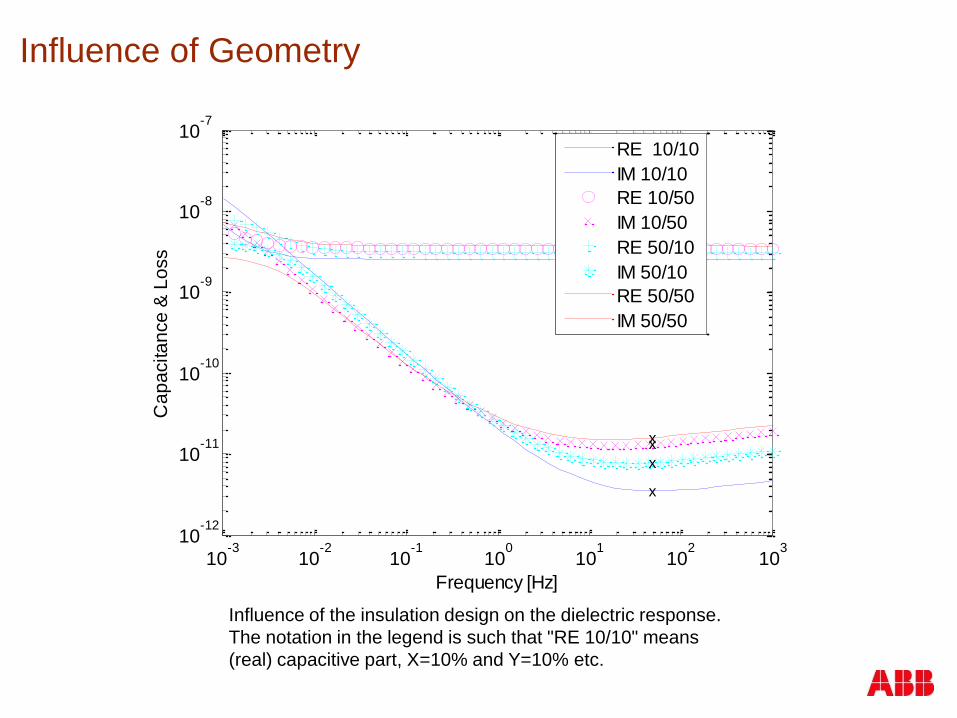
Influence of Geometry
10-3
10-2
10-1
100
101
102
103
10-12
10-11
10-10
10-9
10-8
10-7
Frequency [Hz]
Ca
pa
cita
nce
& L
oss +
x
+
x
+
x
+
x
RE 10/10
IM 10/10
RE 10/50
IM 10/50
RE 50/10
IM 50/10
RE 50/50
IM 50/50
Influence of the insulation design on the dielectric response.
The notation in the legend is such that "RE 10/10" means
(real) capacitive part, X=10% and Y=10% etc.

The X-Y model - Tool for Analysis
X
1-X
Y 1-Y
Oil
Barrier
Spacer
X
1-X
Y 1-Y
Oil
Barrier
Spacer
Insert the materials in the geometry
Simplified geometry
Materials characteristics
Model
Dry transformer
Wet transformer
10-6
10-4
10-2
100
102
104
10-2
10-1
100
101
102
103
LOG FREQUENCY
LO
G E
PS

The X-Y model - Tool for Analysis
•X & Y for the XY-model
•Temperature (ºC)
•DFR measurements data
General Input Parameters
•% moisture,
•Oil conductivity
•Amount of contamiantion
•High Core ground resistance
•
•
General Output Parameters
for the analysis tool

DFR- Cases

© ABB Group April 19, 2011 | Slide 42
Preventive Auto issue
Carbon trackingBushing Shield Problem
Resistor in the core groundPump Bearing Failure
Contamination

Case #1 – New Transformer
•HV kV: 220 kV (Y- connection)
•XV kV : 72.5 kV (Y- connection)
•TV kV: 12.0 kV (- connection)
•Top rating MVA: 125 MVA at 50 Hz
•Cooling Class: ONAN/ONAF/ONAF
•Average oil temperature : 20 C

Case #1 – New Transformer – Test Configurations
HV UST XV
HV UST TV
XV to ground
HV to ground
TV to ground
XV HV
XV HV
Core TV
TV
XV HV
XV HV
Core TV
TV

Case #1 – New Transformer – HV UST XV

Case #1 – Temperature influence
An Error in Temperature can affect the estimate of
moisture in the insulation

Case #1 – New Transformer – Geometrical prop.
An Error in %X and %Y can affect the accurcy of the results


Case #3: Unit Gassing in Operation
HV: 525 kV
XV: 15 kV
MVA: 236 MVA
Coolant: Mineral oil

Case #3: Unit Gassing in Operation
The unit was producing combustible gasses. No
obvious fault could be detected.
Customer performed routine tests, and all were
normal
DFR- measurements were done as a last resort to
help locate the source so the unit could be repaired in
the field without returning it to the factory.
ABB performed H-ground, X-ground and H-X DFR
tests

Case #3: Unit Gassing in OperationCombustible Gases
0
10
20
30
40
50
60
70
80
90
07-Aug-06 09-Aug-06 11-Aug-06 13-Aug-06 15-Aug-06 17-Aug-06 19-Aug-06 21-Aug-06 23-Aug-06
Date
C2H
2, H
2 (p
pm
)
0
50
100
150
200
250
To
tal C
om
b. G
as
Hydrogen (H2)
Methane (CH4)
Acetylene (C2H2)
Ethane (C2H6)
Ethylene (C2H4)
Total Combustible Gas

Case #3: Winding Configuration
XV
XV
HV
HV
Co
re XV
XV
HV
HV
HV
HV
Co
re
Test Set-up
-CHL
-CL
-CH
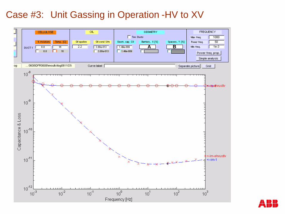
Case #3: Unit Gassing in Operation -HV to XV
A B
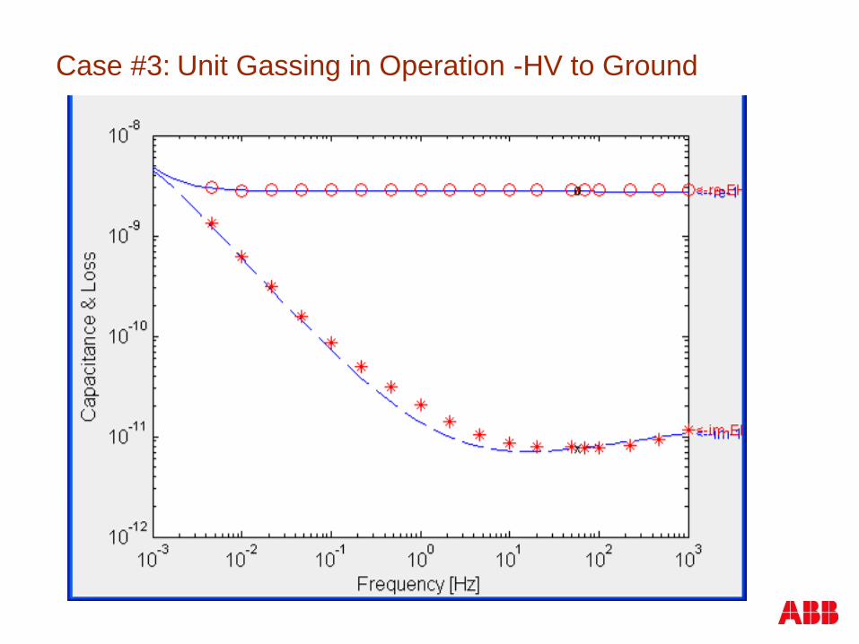
Case #3: Unit Gassing in Operation -HV to Ground

Case #3: Unit Gassing in Operation
1. The tip up test on the HV indicated
the potential of a loose connection
2. The DFR test on the HV indicated
the presence of a parallel capacitance
resistance circuit

Case #3: Unit Gassing in Operation
The inspection of the shielding tube showed that the sleeve (also called union coupling) that connects the vertical tube with the horizontal Y tubes at the HV windings connection was loose and did not make proper contact.
There had been arcing at the sleeve and also between the cable inside the shielding tube and the tube.

Case: Unit Gassing in Operation - After Repair
A B

Summary
Determine moisture of the insulation
Abnormal DGA
Just want to know the condition of your transformer
Suspect contamination or core issues


What is SFRA?
SFRA means: Sweep Frequency Response Analysis
SFRA is: “An off-line, non-destructive diagnostic technique”
SFRA shows: Spectrum changes mechanical
deformation
SFRA is: Comparative method (two spectra are compared)
SFRA is: Measurement of electrical response
(from 10 Hz to 2 MHz or more).
SFRA can detect mechanical
problems without opening the
transformer.

Zp,out Uout
Iout
Us
Zs
Zp,inUin
Iin
s
Inductances and capacitances act together, creating resonances
What is FRA? (principle of FRA)
out10
in
( )FRA(dB) 20log
( )
U f
U f

Typical FRA spectrum (logarithmic scales):
Magnitude in dB
Logarithmic frequency scaleStarts at: some Hertz (e.g. 10 Hz)
Stops at: some Megahertz (e.g. 2 MHz)
What is FRA ? What the responses look like?
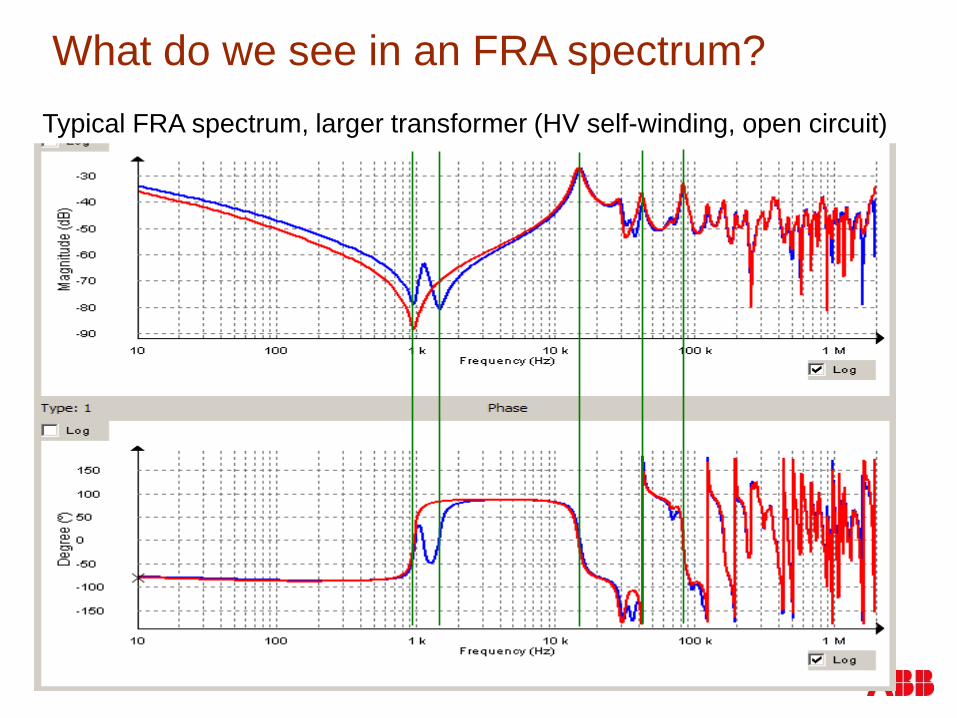
What do we see in an FRA spectrum?
Typical FRA spectrum, larger transformer (HV self-winding, open circuit)

- axial winding collapse
- clamping failure
- hoop buckling
- shorted turns
- bad core grounding
- open, broken, grounded, … tertiary winding
- bad contact (?)
- …
What is FRA ?
What we can detect today using FRA?
Changes in FRA response reveal a wide range of
fault types:

Two Examples
1) Short-circuited turns
2) Hoop Buckling

Example: Short-circuited turns
Frequency [MHz]
Mag
nit
ud
e [
dB
]
Phase A has clear short-circuit behavior
(reduction of the inductance).
The other two phases have normal open
circuit measurement behavior.

Example: Short-circuited turns

Example: Hoop Buckling
Hoop buckling means:
- Internal winding (usually LV)
collapses
-Reason:
- large (compressive) radial
forces on the winding during a
short-circuit fault.

Example: Hoop Buckling
Suspect Unit
(LV winding)Clear shift left
at critical
frequency

Example: Hoop Buckling
Clear deformation
in winding

When should we perform FRA?

When should we perform FRA?
After manufacturing
Fingerprint measurement
Create first reference
As part of a routine diagnostic protocol
To check for changes during service time
After installation or relocation
To check for transformer integrity

When should we perform FRA?
In case of troubles:
After a major change in on-line diagnostic condition
After a transformer alarm
After a significant through-fault event
After external failures compromising the transformer condition
(short circuits, close lightning impact, ...)
To compare with a sister unit in troubles

DFR Measurements
SFRA-Measurements

FRAX-101 produced by
Megger Group
ABB-Switzerland is working with this device
M5300 produced by Doble
ABB-USA is working with this device
FRAnalyzer
produced by Omicron
ABB-Germany is working with this device
Agilent (HP) – Network analyzerGeneral device – Not dedicated to FRA
Traftek produced by
B&C Diagnostics
FRA-100 produced
by Phenix
FRAmit
produced by
Utility &
Industrial
Products, Inc
FRA 5310
produced by
Haefely
SoFT produced
by ABBComplete transformer
fingerprinting
What is FRA ? What the devices look like?

Measurement procedure (do not forget!!!)
Take Pictures:
-Name plate
-Transformer
-Connections

Typical test connection (three key elements):• The unit under test (Transformer)
• The FRA device (Many possibilities)
• The cabling (three coaxial cables)
TransformerUnderTest
Measurement procedure (setup installation)
AC Voltage
(Swept frequency or time pulse)
FRA Device

Typical test connection (Avoid loops in GND connections)
Source Signal Cable
Reference
Signal Cable
Source and ReferenceCable Shield Grounds
Response
Signal Cable
TransformerUnderTest
ResponseCable Shield Ground
FRA Device
PhaseBushing
NeutralBushing
Sw
ep
t F
req
uen
cy
AC
Vo
ltag
e
Very important: keep the loop
formed by cable shield to ground
connection and bushing as small
as possible!
The transformer tank is the reference ground.
Measurement procedure (setup installation)

Check your leadsout
10
in
( )FRA(dB) 20log
( )
U f
U f
Measurement procedure (before to start)
Small scale in
vertical axis:
- Look for available reference data:
- Fingerprint measurements (i.e., from same unit)
- Data from twin / sister units
- Prepare a list of the configurations you want to test
Capacitive
Inductive
HV self-winding (open circuit)
LV self-winding (open circuit)
HV self-winding (short circuit)
LV self-winding (short circuit)
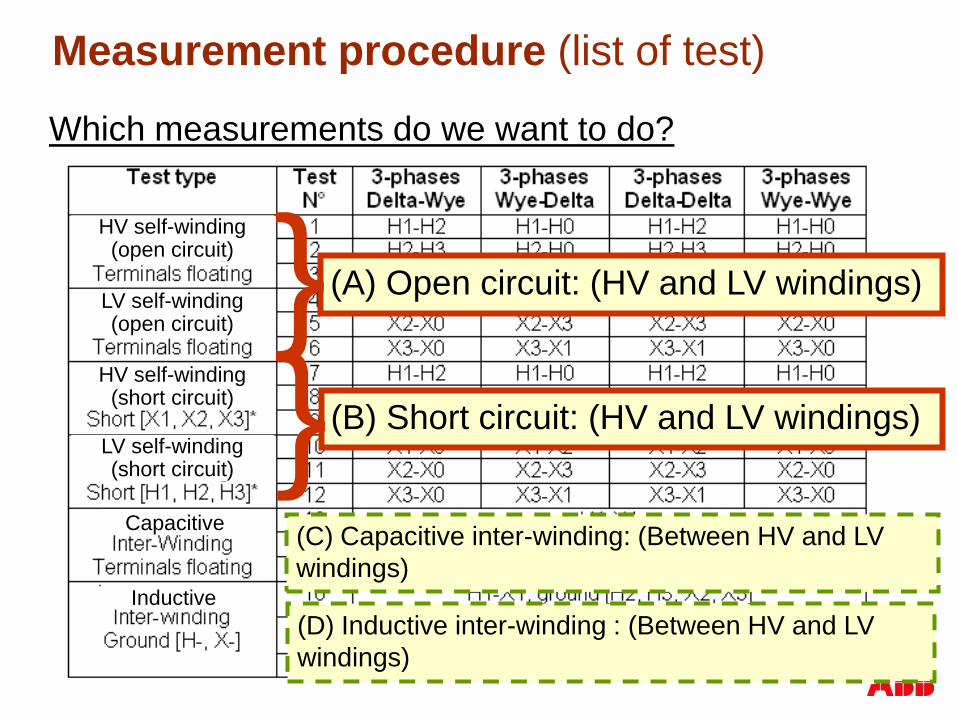
Measurement procedure (list of test)
(C) Capacitive inter-winding: (Between HV and LV
windings)
(D) Inductive inter-winding : (Between HV and LV
windings)
(A) Open circuit: (HV and LV windings)}(B) Short circuit: (HV and LV windings)}
Which measurements do we want to do?

Measurement procedure
Why open circuit measurements?
We can see:
Winding short-circuits
Broken delta winding
Core related problems (circulating currents, bad joints, …)
Why short circuit measurements?
Precise short-circuit reactance measurement
close agreement between phases (0.1 dB rule)
Very good reproducibility within the whole frequency range
Not affected by core magnetization

DFR Measurements
SFRA-Analysis

Analysis:
-Baseline Measurements
-Sister units
-Phase to Phase

Typical results: Large transformer
“LV sc”
“LV oc”
“HV oc”
“HV sc”

Configuration - Self-Winding (Open circuit)
The Low Voltage terminals are open (floating)
Typical results: Open- vs. short circuit
Configuration – Self-Winding (Short circuit)
The Low Voltage terminals are short-circuited
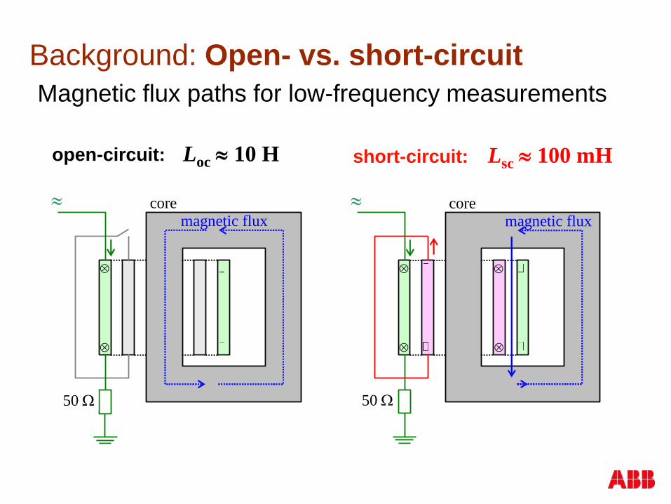
Background: Open- vs. short-circuit
50
magnetic flux
core
50
core magnetic flux
Magnetic flux paths for low-frequency measurements
open-circuit: short-circuit:Loc 10 H Lsc 100 mH

Open-circuit test: Y vs. Delta
Configuration – Self-Winding (Open circuit)
Voltage injection /
Voltage reference
Voltage response
Star configuration Delta configuration
Voltage injection
Voltage reference
The Low Voltage terminals are open (floating)
H3-H0
test
Voltage response
Y1-Y3
test

Typical results: Areas of influences (Approx.)
Core influence

Winding influence
Typical results: Areas of influences (Approx.)

Leads, grounding influence
Typical results: Areas of influences (Approx.)

Comparing phase by phase : Before and
after DC Winding resistance test
Typical results: Influence of winding resistance test
Measurements before and after winding resistance test

Typical results: Cable shield grounding at bushing
Cable shields
grounded
Cable shields
NOT grounded
Cable shield must be connected at both ends

Oil influence in FRA signatures (HV Winding):
With Oil
Without Oil

Tap Position influence in FRA signatures
Position 1
Position 17 Position 9

Noise from Instrumentation!

Short circuit test
0.1 dB or less

Short-circuit test: 0.1dB criterion
The short-circuit inductance is proportional to the cross-
section area A of the main channel:
2
0sc
NL
h
AHV
LVA
main
channel< 0.1dB means that
A changes by < 1%

Good practices: Short circuit Connection
Reduce short circuit cable resistance and inductance
by using several conductors in parallel.
Very good Good
SFRA- Cases

Case # 1
Residual magnetization

Case # 1 Residual magnetization
FRA measurement identified residual
magnetization
The outer phases (A & B) did not align well with
one another at the low frequency region.
All Short circuit tests showed symmetry between
windings.
It was discovered that the field test specialist
performed a DC resistance test one day earlier.

Case # 1 Residual magnetization
All three phases show separation
due to the core being magnetized100 Hz – 4 kHz

Case # 1 FRA results after Demagnetizing
A & C phase are aligned
phase B shows higher impedance as usual
demagnetization

Case # 2
Shorted turns

Case # 2 Shorted turns
Ratio test indicated shorted winding turn on phase B
FRA was made to decide whether HV or LV winding had
failed

Case # 2 Shorted turns – Which winding (HV or LV)..??
HV open circuit
Phase B
Phase A & C
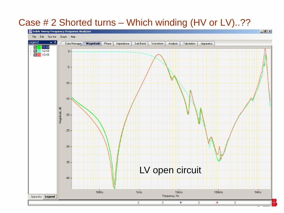
Case # 2 Shorted turns – Which winding (HV or LV)..??
LV open circuit

Case # 2 Shorted turns – Which winding (HV or LV)..??
HV short circuit
(i.e., HV measured and
LV short circuited)
Lower inductance due to
shorted turns in HV
phase B

Case # 2 Shorted turns - lesson learned
Both HV and XV open circuit tests indicate that phase B has shorted turns
HV short circuit test indicates that HV winding has shorted turn
HV short deviation at low frequency also indicates that HV B-phase has extra losses

Case # 3
Earthed tertiary
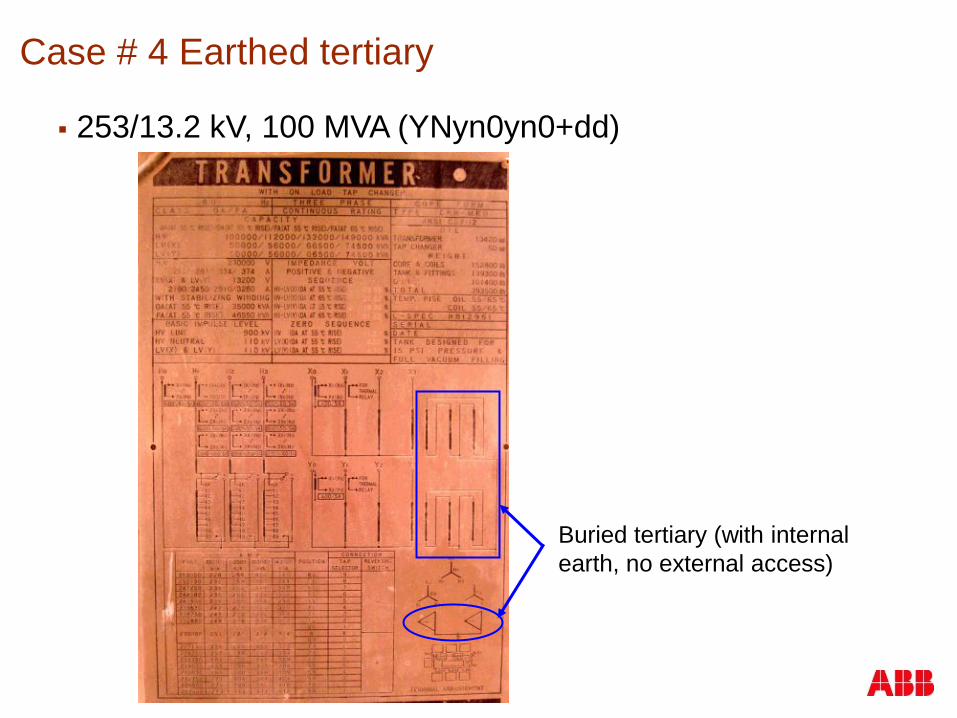
Case # 4 Earthed tertiary
253/13.2 kV, 100 MVA (YNyn0yn0+dd)
Buried tertiary (with internal
earth, no external access)

Case # 4 Earthed tertiary
253/13.2 kV, 100 MVA (YNyn0yn0+dd)
LV open circuit
Phase asymmetry due to
earthed tertiary (buried)

Case # 4 Earthed tertiary
240/72 kV, 150MVA (YNyn0+d)
Tertiary brought out and earthed externally
Possible to remove tertiary earth keeping delta intact
Tertiary brought out
and earthed

Case # 4 Earthed tertiary
Tertiary earth removed and delta intact
Symmetry between phases is preserved
delta tertiary intact, earth
connection removed
LV open circuit

© ABB Inc.April 19, 2011 | Slide 115
RemindersAutomation & Power World 2011
Please be sure to complete the workshop evaluation
Professional Development Hours (PDHs) and
Continuing Education Credits (CEUs):
You will receive a link via e-mail to print
certificates for all the workshops you have attended
during Automation & Power World 2011.
BE SURE YOU HAVE YOUR BADGE SCANNED
for each workshop you attend. If you do not have
your badge scanned you will not be able to obtain
PDHs or CEUs.

© ABB Group April 19, 2011 | Slide 116