advanced instrumentation, information, and … iic system technologies/m2...advanced...
TRANSCRIPT

PNNL-20671
Prepared for the U.S. Department of Energy under Contract DE-AC05-76RL01830
Advanced Instrumentation, Information, and Control System Technologies: Nondestructive Examination Technologies – FY11 Report RM Meyer P Ramuhalli JB Coble LJ Bond August 2011


PNNL-XXXXX
Advanced Instrumentation, Information, and Control System Technologies: Nondestructive Examination Technologies – FY11 Report RM Meyer P Ramuhalli JB Coble LJ Bond August 2011 Prepared for the U.S. Department of Energy under Contract DE-AC05-76RL01830 Pacific Northwest National Laboratory Richland, Washington 99352


iii
Abstract
Licensees of commercial nuclear power plants in the United States are expected to submit license renewal applications for the period of operation of 60 to 80 years which has also been referred to as long term operation (LTO). The greatest challenges to LTO are associated with degradation of passive components as active components are routinely maintained and repaired or placed through maintenance programs. Some passive component degradation concerns include stress corrosion cracking of metal components, radiation induced embrittlement of the reactor pressure vessel, degradation of buried piping, degradation of concrete containment structures, and degradation of cables.
Proactive management of passive component aging employs three important elements including online monitoring of degradation, early detection of degradation at precursor stages, and application of prognostics for the prediction of remaining useful life. This document assesses several nondestructive examination (NDE) measurement technologies for integration into proactive aging management programs. The assessment is performed by discussing the three elements of proactive aging management identified above, considering the current state of the industry with respect to adopting these key elements, and analyzing measurement technologies for monitoring large cracks in metal components, monitoring early degradation at precursor stages, monitoring the degradation of concrete containment structures, and monitoring the degradation of cables.
Specific and general needs have been identified through this assessment. General needs identified include the need for environmentally rugged sensors that can operate reliably in an operating reactor environment, the need to identify parameters from precursor monitoring technologies that are unambiguously correlated with the level of pre-macro defect damage, and a methodology for identifying regions where precursor damage is most likely to initiate.


v
Summary
Long-term operation (LTO) of the current fleet of nuclear power plants (NPPs) has been identified as high priority by the U.S. Department of Energy as part of an overall effort to meet rising demands for electricity and meet international obligations to lower greenhouse gas emissions. NPP operators are granted an initial license term of 40 years to operate and are eligible for multiple 20-year license extensions beyond the initial expiration. It is anticipated that most plants will apply for and be granted the initial 20-year license extension (21 initial license renewals have been approved thus far) but subsequent license extensions are less clear due to uncertainties regarding the performance of safety critical systems, structures and components (SSCs) beyond 60 years.
Active SSCs (including pumps, valves, and rotating machinery) are well managed and undergo routine maintenance and repair/replacement activities through plant maintenance programs and are not expected to challenge LTO of NPPs. Passive SSCs (pipes, vessels, concrete, and cables) are managed by periodic inservice inspection (ISI) and aging management plans (AMPs). Aging degradation of passive components is expected to pose a threat to LTO of NPPs because not all potential aging mechanisms are well understood and the physical size of some passive SSCs could make their replacement impossible or uneconomical. As a consequence, issues related to LTO are associated with passive SSCs.
Current approaches to managing the aging degradation of passive SSCs include periodic ISI. Periodic ISI involves the examination of SSCs at regular intervals with respect to time. For this philosophy to be effective, the inspection interval should be short with respect to the time it takes for the degradation to progress from inception to failure. Many degradation mechanisms begin with an incubation period during which damage at the microscopic level coalesces to impose gross physical deformation. At this point, the degradation mechanism has entered a new phase in which the severity of the gross physical deformation increases until failure. Periodic ISI is applied at NPPs using nondestructive examination (NDE) techniques that are insensitive to the incubation phase of degradation. As practiced, periodic ISI is most effective at managing degradation mechanisms characterized by short incubation phases relative to the phase of gross physical deformation growth. In NPPs, however, there are certain mechanisms (such as stress corrosion cracking) that are characterized by long incubation phases and short crack growth phases. In addition to challenges posed by some existing mechanisms, periodic ISI may be inadequate to manage mechanisms yet to be discovered.
To manage the challenging degradation mechanisms and new mechanisms as they occur, a more proactive approach to aging management could be implemented employing elements of advanced diagnostics, on-line monitoring, and prognostics. Implementation of this philosophy in the current fleet of light-water reactors (LWRs) will require adaptation of existing measurement technologies and development of new technologies to perform measurements on-line to ensure timely detection of degradation and to ensure sampling of degradation is sufficient to support the implementation of prognostics architectures. In addition, technology adaptation and development will be required to implement technologies in the field that are sensitive to early precursor stages of damage.
This document assesses measurement technologies with respect to their potential integration into a proactive aging management program employing online monitoring, advanced diagnostics, and prognostics. For remaining useful life (RUL) estimations, NDE measurements must allow appropriate characterization of degradation mechanisms so that the correct degradation models are applied. Further,

vi
useful RUL predictions require the current state of a component to be assessed with good accuracy. This accuracy requirement is transferred to NDE technologies that must be able to characterize flaw significance with high accuracy. To assist in the assessment of NDE technologies, they are classified as technologies for monitoring large cracks in metal components, technologies for monitoring cable degradation, technologies for monitoring early degradation (precursors), and technologies for monitoring concrete containment structures.
Technologies assessed for large crack detection in metal components include acoustic emission (AE), guided ultrasonic waves (GUW), diffuse ultrasonic wave fields (DUW), phased array ultrasonic testing (PA-UT), and eddy current testing (ET). Technologies assessed for monitoring cable degradation include time domain reflectometry and line resonance analysis. A formal approach is applied to the assessment of technologies for monitoring large cracks in metal components and for monitoring cable degradation. These technologies are relatively mature and most have been demonstrated in the field of the nuclear power or other industries. The formal approach assesses technologies by considering five parameters of relevance to proactive management of degradation: i) technology maturity level, ii) sensitivity, iii) measurement frequency, iv) flaw characterization capability, v) and accessibility. Early degradation or precursor monitoring technologies considered in this assessment include nonlinear acoustics, acousto-ultrasonics, magnetic Barkhausen noise, and magnetic loop measurements. NDE technologies assessed for monitoring concrete degradation include bulk wave ultrasonic testing, half-cell potential and surface potential, linear polarization resistance, thermographic imaging, radiographic testing, and inspections with microwave or radar signals.
The assessment of NDE technologies for proactive aging management is performed to reveal technical gaps that could inhibit the implementation of proactive aging management strategies. While the assessment can reveal gaps specific to each individual technology, some general themes do emerge. General technical issues or gaps identified through this assessment are summarized below:
• Environmentally rugged sensors are needed that can operate reliably for long periods at temperatures near 300°C. Sensors for monitoring reactor pressure vessel internal components will also need to be resistant to exposure by neutron radiation and eddy current sensors deployed for online monitoring of steam generator tubes also need to be resistant to moisture and steam.
• Precursor NDE signal parameters that exhibit an unambiguous correlation with the level of pre-macro defect damage are needed for many forms of degradation relevant to LWRs. The nonlinearity parameter has exhibited good correlation with damage in fatigue specimens prior to cracking. Parameters with similar behavior are needed for stress corrosion cracking and embrittlement.
• The placement of sensors for precursor monitoring presents a challenge. Precursor monitoring technologies need to be able to regularly sample large volumes of material or rapidly scan a component to identify regions where damage exists in precursor state. The scanning can be limited to regions of anticipated damage initiation based on experience and or modeling/simulations.
In addition the general needs identified above, some more specific needs have been identified for technologies to monitor large cracks in metal components. These are provided for each technology below:
• Acoustic Emission (AE) – The formula contained in Appendix I of Article 13 of Section V of the ASME Code relating crack growth rate to AE activity is generalized and conservative. The accuracy provided by this formula is not sufficient to base predictions of RUL. Achieving the necessary

vii
accuracy to perform RUL predictions from AE data may require the formulation of component/material specific crack growth rate to AE activity relationships.
Currently, Section XI of the ASME Code sanctions the use of online monitoring with AE to supplement periodic NDE. In this application, AE is limited to monitoring the growth of existing flaws that have been sized using alternative NDE techniques. The detection of defects with AE must be verified with alternative NDE techniques. To experience the full advantages of proactive aging management, online monitoring with AE should replace periodic NDE. In this case, AE will be relied upon for accurate detection of new flaws and defects. To keep the false call probability low, sophisticated algorithms for signal discrimination should be developed.
AE sensors failed due to thermal exposure during an online monitoring demonstration at the Limerick Unit 1 generating station. Testing of modern AE equipment in equivalent environments is necessary to assess long-term reliability.
• Guided Ultrasonic Waves (GUW) – High temperature transducers for GUW monitoring need to be developed and validated with respect to long term reliability. Currently, the technique is unable to fully characterize a flaw without some prior knowledge regarding the state of the flaw. The sensitivity of the technique to anticipated forms of degradation in specific LWR components under operating conditions should be assessed.
• Diffuse Ultrasonic Wave Field (DUW) – DUW requires multiple reflections of injected energy from the boundaries of the component and has been tested on relatively small components. The feasibility of applying the technique on components and materials of interest to operating LWRs should be assessed. Further, the influence of reactor coolant noise on the performance of the technique should also be assessed.
• Phased Array Ultrasonic Testing (PA-UT) – PA-UT is mostly inhibited from online monitoring applications due to the high temperature environment. The high temperature environment also requires the use of coupling alternatives to water.
• Eddy Current Testing (ET) – ET is mostly considered a surface examination technique except for the examination of thin wall tubing such as steam generator tubing. ET is routinely deployed for steam generator inspections during outages but online monitoring will require the development of techniques to perform ET inspections from tube outer diameters.
For concrete containments, thorough inspections of basemats are an issue. Inspection technologies are unable to penetrate the full thickness of the basemat which is heavily reinforced. Further, access to the soil side of the basemat is restricted.


ix
Acknowledgments
The effort that Kay Hass expended in the final preparation and formatting of this report is gratefully acknowledged.

xi
Acronyms and Abbreviations
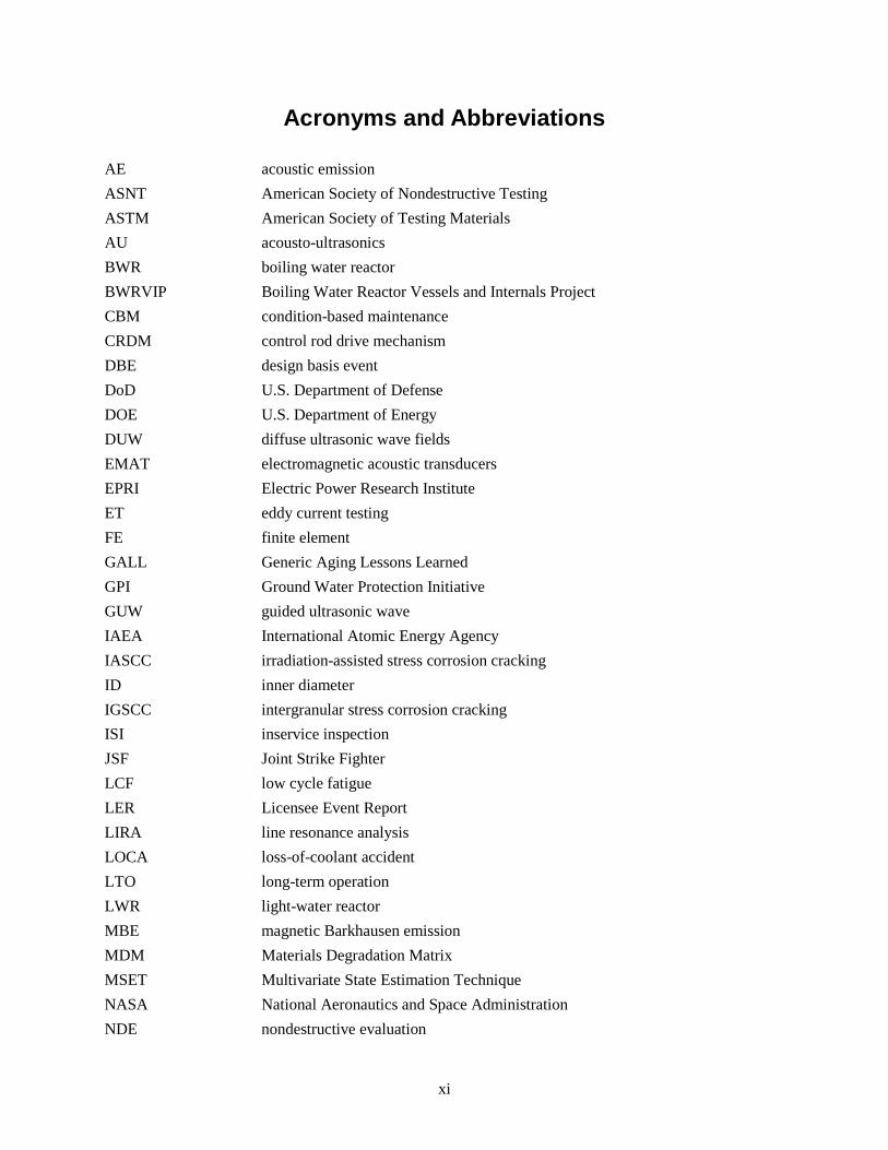
AE acoustic emission ASNT American Society of Nondestructive Testing ASTM American Society of Testing Materials AU acousto-ultrasonics BWR boiling water reactor BWRVIP Boiling Water Reactor Vessels and Internals Project CBM condition-based maintenance CRDM control rod drive mechanism DBE design basis event DoD U.S. Department of Defense DOE U.S. Department of Energy DUW diffuse ultrasonic wave fields EMAT electromagnetic acoustic transducers EPRI Electric Power Research Institute ET eddy current testing FE finite element GALL Generic Aging Lessons Learned GPI Ground Water Protection Initiative GUW guided ultrasonic wave IAEA International Atomic Energy Agency IASCC irradiation-assisted stress corrosion cracking ID inner diameter IGSCC intergranular stress corrosion cracking ISI inservice inspection JSF Joint Strike Fighter LCF low cycle fatigue LER Licensee Event Report LIRA line resonance analysis LOCA loss-of-coolant accident LTO long-term operation LWR light-water reactor MBE magnetic Barkhausen emission MDM Materials Degradation Matrix MSET Multivariate State Estimation Technique NASA National Aeronautics and Space Administration NDE nondestructive evaluation

xii
NDT nondestructive testing NEI Nuclear Energy Institute NPP nuclear power plant NRC U.S. Nuclear Regulatory Commission NUREG U.S. Nuclear Regulatory Commission Regulation OD outer diameter PA-UT phased-array ultrasonic testing PFM post fault monitoring PHM prognostics and health management POD probability of detection PTS pressurized thermal shock PVC polyvinyl chloride PWR pressurized water reactor PWSCC primary water stress corrosion cracking RI-ISI risk-informed inservice inspection RPV reactor pressure vessel RUL remaining useful life SCC stress corrosion cracking SSC safety structures and components TDR time-domain reflectometry TGSCC transgranular stress corrosion cracking TOFD time-of-flight diffraction TRL Technology Readiness Level UPTI Underground Piping and Tanks Integrity Initiative XLPE cross-linked polyethylene

xiii
Contents
Abstract ........................................................................................................................................................ iii Summary ....................................................................................................................................................... v Acknowledgments ........................................................................................................................................ ix Acronyms and Abbreviations ...................................................................................................................... xi 1.0 Introduction ....................................................................................................................................... 1.1
1.1 Approach ................................................................................................................................... 1.3 1.2 Outline of Document ................................................................................................................. 1.4
2.0 Life-Limiting Concerns ..................................................................................................................... 2.1 2.1 Stress Corrosion Cracking ......................................................................................................... 2.2 2.2 Embrittlement ............................................................................................................................ 2.3 2.3 Buried Piping ............................................................................................................................ 2.4 2.4 Containment Structures ............................................................................................................. 2.6 2.5 Cables ........................................................................................................................................ 2.7
3.0 Proactive Management of Aging Degradation .................................................................................. 3.1 3.1 Early Detection of Degradation ................................................................................................. 3.1 3.2 Online Condition Monitoring .................................................................................................... 3.2 3.3 Prognostics ................................................................................................................................ 3.3 3.4 PHM Activities .......................................................................................................................... 3.4
4.0 Industry State-of-the-Art ................................................................................................................... 4.1 4.1 ASME Boiler and Pressure Vessel Code, Section XI ............................................................... 4.1
4.1.1 Inspection Techniques .................................................................................................... 4.1 4.1.2 Inspection Schedules ...................................................................................................... 4.1 4.1.3 Component Classification .............................................................................................. 4.2 4.1.4 Risk-Informed Inservice Inspection ............................................................................... 4.2 4.1.5 Inspection of Concrete Containments ............................................................................ 4.2
4.2 Acoustic Emission ..................................................................................................................... 4.3 4.3 EPRI COLM Workshop, Atlanta, Georgia ............................................................................... 4.5 4.4 Empirical Methods for System Monitoring............................................................................... 4.6 4.5 OLM in Nuclear Power Plants .................................................................................................. 4.7
4.5.1 OLM Applications in the USA ....................................................................................... 4.8 4.5.2 International OLM Applications .................................................................................... 4.9
5.0 Measurement Technology Assessment.............................................................................................. 5.1 5.1 Assessment of Technologies for Monitoring Large Cracks ...................................................... 5.1
5.1.1 Acoustic Emission .......................................................................................................... 5.4 5.1.2 Guided Ultrasonic Waves ............................................................................................... 5.6 5.1.3 Phased-Array Ultrasonic Testing ................................................................................... 5.8

xiv
5.1.4 Diffuse Ultrasonic Wave Fields ................................................................................... 5.10 5.1.5 Eddy Current Testing ................................................................................................... 5.11
5.2 Assessment of Technologies to Monitor Cable Degradation .................................................. 5.12 5.2.1 Time Domain Reflectometry ........................................................................................ 5.12 5.2.2 Line Resonance Analysis ............................................................................................. 5.12
5.3 Technologies Sensitive to Early Degradation in Metals (Precursor Monitoring) ................... 5.13 5.3.1 Nonlinear Acoustics ..................................................................................................... 5.13 5.3.2 Acousto-ultrasonics ...................................................................................................... 5.14 5.3.3 Magnetic Barkhausen Emission ................................................................................... 5.15 5.3.4 Magnetic Loop Parameters ........................................................................................... 5.16 5.3.5 Other Techniques ......................................................................................................... 5.16
5.4 Concrete .................................................................................................................................. 5.17 5.4.1 Ultrasonic Testing ........................................................................................................ 5.17 5.4.2 Thermographic Imaging ............................................................................................... 5.17 5.4.3 Radiographic Testing ................................................................................................... 5.17 5.4.4 Half-cell Potential and Surface Potential ..................................................................... 5.18 5.4.5 Polarization Resistance ................................................................................................ 5.18 5.4.6 Microwave Techniques ................................................................................................ 5.18 5.4.7 Other Techniques for Monitoring of Tendons and Reinforcing Steel .......................... 5.18
6.0 Discussion/Technical Gaps ................................................................................................................ 6.1 6.1 Critique of Technologies for Monitoring Crack Growth .......................................................... 6.1 6.2 Critique of Technologies for Precursor Monitoring .................................................................. 6.2 6.3 Critique of NDE Technologies for Assessment of Concrete Containment Structures .............. 6.3 6.4 Monitoring of Buried Piping ..................................................................................................... 6.3 6.5 General Technical Gaps ............................................................................................................ 6.4
7.0 Summary/Conclusions ....................................................................................................................... 7.1 8.0 References ......................................................................................................................................... 8.3

xv
Figures
1.1 Illustration of Degradation that Progresses in a Slow, Linear Manner .............................................. 1.2 1.2 Illustration of Degradation Trend Exhibiting Long Initiation Time Followed by Rapid
Growth to Failure ............................................................................................................................... 1.2 1.3 Summary of Major Degradation Phenomena Experienced Over the Operating History of
LWRs ................................................................................................................................................. 1.3 2.1 Modes of Degradation of Most Significant Concern to Extended Operation by Expert Panel ......... 2.2 2.3 Trend of Embrittlement Degradation Progression to Failure ............................................................. 2.4 2.4 Depiction of a Typical Cable Architecture ........................................................................................ 2.9 3.1 Illustration of Stages of Degradation and Correlating Measurement Methodologies ........................ 3.2 4.1 Photograph of Acoustic Emission Application to Monitoring an RPV to Nozzle Safe End
Weld at Limerick Unit 1 .................................................................................................................... 4.4 4.2 Modules of a Typical Health Management System ........................................................................... 4.6 5.1 Plot Showing the Origin of AE Signals Relative to an Array of AE Sensors .................................... 5.5 5.2 Example of an Amplitude Distribution Obtained from the Collection of AE Signals ....................... 5.6 5.3 Photograph of Data Acquisition Hardware for PA-UT and Integration with Computer
Interface ............................................................................................................................................. 5.9 5.4 Photograph of PA-UT Probe ............................................................................................................ 5.10
Tables
2.1 Distribution of Low Voltage Circuits in a Typical NPP .................................................................... 2.8 3.1 Conferences and Meetings with an Emphasis on PHM ..................................................................... 3.4 4.1 Summary of NDE Technologies Included in Section XI of the ASME Boiler and Pressure
Vessel Code ....................................................................................................................................... 4.1 5.1 Technology Readiness Level Definitions and Their Descriptions ..................................................... 5.2


1.1
1.0 Introduction
Long-term operation (LTO) of the current fleet of nuclear power plants (NPPs) has been identified as high priority by the U.S. Department of Energy (DOE) (DOE 2011) as part of an overall effort to meet rising demands for electricity and meet international obligations to lower greenhouse gas emissions. NPP operators are granted an initial license term of 40 years to operate and are eligible for multiple 20-year license extensions beyond the initial expiration. It is anticipated that most plants will apply for and be granted the initial 20-year license extension (21 initial license renewals have been approved thus far) (NRC 2011) but sequential license extensions are less clear due to uncertainties regarding the performance of safety critical systems, structures and components (SSCs) beyond 60 years.
Active SSCs (including pumps, valves, and rotating machinery) are well managed and undergo routine maintenance and repair/replacement activities through plant maintenance programs and are not expected to challenge LTO of NPPs. Passive SSCs (pipes, vessels, concrete, and cables) are managed by periodic inservice inspection (ISI) and aging management plans (AMPs). Aging degradation of passive components is expected to pose a threat to LTO of NPPs because not all potential aging mechanisms are well understood and the physical size of some passive SSCs could make their replacement impossible or uneconomical. As a consequence, issues related to LTO are associated with passive SSCs.
Current approaches to managing the aging degradation of passive SSCs include periodic ISI. Periodic ISI involves the examination of SSCs at regular intervals with respect to time. For this philosophy to be effective, the inspection interval should be short with respect to the time it takes for the degradation to progress from inception to failure. Many degradation mechanisms begin with an incubation period during which damage at the microscopic level coalesces to impose gross physical deformation of the material. At this point, the degradation mechanism has entered a new phase in which the severity of the gross physical deformation increases until failure. Periodic ISI is applied at NPPs using NDE techniques that are insensitive to the incubation phase of degradation. As practiced, periodic ISI is most effective at managing degradation mechanisms characterized by short incubation phases relative to the phase of gross physical deformation growth, as illustrated in Figure 1.1. In NPPs, however, there are certain mechanisms (such as stress corrosion cracking) that are characterized by long incubation phases and short crack growth phases (see Figure 1.2). In addition to challenges posed by some existing mechanisms, periodic ISI may be inadequate to manage mechanisms yet to be discovered. According to Wilkowski (2002), a new degradation mechanism can be anticipated approximately every 7 years (see Figure 1.3).

1.2
Figure 1.1. Illustration of Degradation that Progresses in a Slow, Linear Manner
Figure 1.2. Illustration of Degradation Trend Exhibiting Long Initiation Time Followed by Rapid
Growth to Failure
Unacceptable Degradation
Initiation Time Crack Propagation
Leve
l of D
egra
datio
n
Time
Unacceptable Degradation
Initiation Time
Crack Propagation
Leve
l of D
egra
datio
n
Time

1.3
Figure 1.3. Summary of Major Degradation Phenomena Experienced Over the Operating History of
LWRs (Wilkowski et al. 2002)
To manage the challenging degradation mechanisms and new mechanisms as they occur, a more proactive approach to aging management could be implemented. Proactive aging management employing elements of advanced diagnostics, on-line monitoring, and prognostics was presented at the ASME Pressure Vessel and Piping meeting in July 2010 (Bond 2010). Implementation of this philosophy in the current fleet of light-water reactors (LWRs) will require adaptation of existing measurement technologies and development of new technologies to perform measurements on-line to ensure timely detection of degradation and to ensure temporal resolution of measurements is sufficient to support the implementation of prognostics architectures. In addition, technology adaptation and development will be required to implement technologies in the field that are sensitive to precursor stages of damage.
1.1 Approach
Several NDE technologies are assessed with respect to potential integration into a proactive aging management plan. For RUL estimations, NDE measurements must allow appropriate characterization of degradation mechanisms so that the correct degradation models are applied. Further, useful RUL predictions require the current state of a component to be assessed with good accuracy. This accuracy requirement is transferred to NDE technologies which must be able to characterize flaw significance with high accuracy. To assist in the assessment of NDE technologies, they are classified as technologies for monitoring large cracks in metal components, technologies for monitoring cable degradation, technologies for monitoring early degradation (precursors), and technologies for monitoring concrete containment structures.
Technologies assessed for large crack detection in metal components include acoustic emission (AE), guided ultrasonic waves (GUW), diffuse ultrasonic wave fields (DUW), phased array ultrasonic testing (PA-UT), and eddy current testing (ET). Technologies assessed for monitoring cable degradation include time domain reflectometry (TDR) and line resonance analysis (LIRA). A formal approach is applied to

1.4
the assessment of technologies for monitoring large cracks in metal components and for monitoring cable degradation. These technologies are relatively mature and most have been demonstrated in the field of the nuclear power or other industries. The formal approach assesses technologies by considering five parameters of relevance to proactive management of degradation: i) technology maturity level, ii) sensitivity, iii) measurement frequency, iv) flaw characterization capability, v) and accessibility. Early degradation or precursor monitoring technologies considered in this assessment include nonlinear acoustics, acousto-ultrasonics (AU), magnetic Barkhausen noise (MBE), and magnetic loop measurements. NDE technologies assessed for monitoring concrete degradation include bulk wave ultrasonic testing (UT), half-cell potential and surface potential, linear polarization resistance, thermographic imaging, radiographic testing (RT), and inspections with microwave or radar signals.
1.2 Outline of Document
Section 2 of this report discusses specific aging degradation concerns in LWRs that may be considered a threat to LTO.
Section 3 introduces proactive aging management by discussing three key elements including early degradation detection, online monitoring, and prognostics for predicting remaining useful life.
Section 4 provides a state of the art for the industry with regard to performing NDE on NPP components, the use of AE for online monitoring and the implementation of advanced pattern recognition software.
Section 5 includes the technology assessments for monitoring large cracks, monitoring early degradation, monitoring cable degradation, and monitoring degradation of concrete containments.
Section 6 includes a discussion of the technology assessment performed in Section 5.
Section 7 contains a summary and conclusions.

2.1
2.0 Life-Limiting Concerns
Life-limiting concerns in LWRs are issues that pose a threat to the long-term operation or continued operation of the current fleet of commercial nuclear power plants in the United States. Life-limiting issues include component degradation, lack of physical access for performing meaningful inspections and assessments of structural integrity, and a lack of confidence among the stakeholders of a nuclear power plant.
Most life-limiting concerns have been identified through collective operating experience of LWRs and knowledgeable experts familiar with specific LWR operating characteristics and general materials behavior. Knowledge of passive SSC aging and degradation issues is distributed among several types of documents including Licensee Event Reports (LERs), U.S. Nuclear Regulatory Commission (NRC) generic correspondence, NRC Regulations (NUREGs), industry reports, etc.
In addition to the distribution of documents above, a compilation of common aging degradation phenomena is include in NUREG-1801, “Generic Aging Lessons Learned” (GALL) (NRC 2001). This document assesses the adequacy of aging management plans for handling specific forms of degradation and indicates if further effort is needed. The GALL document was developed in response to industry requests to receive license renewal credit for existing plant programs or activities to handle degradation. The GALL document represents the efforts of the NRC to provide industry with a generic basis by which to assess their specific programs or activities for license renewal.
Analysis of prior operating experience is not sufficient to address concerns facing LWRs as they move into LTO. A proactive approach is required in an effort to assess where degradation is likely to occur during extended operation. The Materials Degradation Matrix (MDM) contains a comprehensive listing of likely degradation mechanisms for BWR and PWR primary system components (Lain 2010). The MDM was created by industry to facilitate implementation of guideline NEI 03-08, “Guidelines for the Management of Materials Issues” (NEI 2003). The matrix includes a pairing of important degradation mechanisms with materials found in BWR and PWR primary systems. For each pair, the applicability of the degradation process is indicated, a code is provided to reference the assessment, and the cells are color coded to indicate the level of research needed to resolve the issue. The assessment was performed based on an expert elicitation process.
The NRC initiated a Proactive Materials Degradation Assessment (PMDA) program in an effort to identify components and materials in LWRs where future degradation is likely to occur. This was achieved through expert elicitation and the Phenomena Identification and Ranking Table (PIRT) process. The expert panel assessed the susceptibility of given components to several degradation mechanisms considering each component’s history, stressors, and time-dependent phenomena, and the level of knowledge regarding the specific degradation processes. The PIRT process was then used to rank issues according to susceptibility and level of knowledge (Andresen et al. 2007).
The Materials Aging Degradation Pathway of the Light Water Reactor Sustainability program held a workshop at the Electric Power Research Institute (EPRI) offices in Charlotte, North Carolina, on August 5 and 6, 2008. The workshop included experts from industry, academia, and national laboratories who were asked to identify areas where research was most needed. Figure 2.1 summarizes the responses elicited from the expert panel. The remainder of Section 4 includes brief discussions about stress

2.2
corrosion cracking (intergranular and irradiation-assisted), radiation embrittlement of the reactor vessel, degradation of buried piping, degradation of concrete containments, and degradation of cables.
Figure 2.1. Modes of Degradation of Most Significant Concern to Extended Operation by Expert Panel
(INL 2010)
2.1 Stress Corrosion Cracking
Stress corrosion cracking (SCC) refers to the degradation phenomenon that consists of crack initiation and growth in susceptible materials under tensile stress and in contact with a corrosive environment. Crack propagation is perpendicular to the applied stress and the time to crack initiation generally decreases with increasing stress levels. SCC can be intergranular (IGSCC) in nature tending to propagate along grain boundaries or it can be transgranular (TGSCC) and propagate through grains (IAEA 2005).
Figure 1.3 shows that SCC was identified as an issue early on in the commercial nuclear industry. Instances of IGSCC in 304 stainless steel components of boiling water reactors (BWRs) were caused by water chemistry conditions that promoted IGSCC. Water chemistry parameters impacting IGSCC susceptibility include pH, conductivity, and electrochemical potential. Maintaining these parameters
2.3
within acceptable ranges can inhibit IGSCC susceptibility. Hydrogen water chemistry programs have been implemented at several BWR utilities to manage IGSCC of 304 stainless steel components (IAEA 2005).
Primary water stress corrosion cracking (PWSCC) is a more recent phenomenon affecting nickel-alloy components in pressurized water reactors (PWRs). Several instances of PWSCC have been identified in Alloy 600 portions of control rod drive mechanism (CRDM) penetrations and the Alloy 82/182 weld material of the J-groove partial penetration welds. Although most of the PWSCC indications have been axial cracks, circumferential cracking has been observed as well. Safety concerns arise from circumferential cracks due to the potential for nozzle ejection. In addition to CRDM penetrations, PWSCC indications have been observed on bottom-mounted instrumentation nozzles and dissimilar metal welds in reactor hot legs (IAEA 2007).
Irradiation-assisted stress corrosion cracking (IASCC) is an intergranular form of cracking that is highly dependent on neutron fluence exposure level in addition to the presence of tensile stress and a corrosive environment. It is of greatest concern for internal components of the reactor pressure vessel (RPV), which are exposed to the highest fluence levels over the reactor lifetime. Neutron fluence thresholds for IASCC of ~5×1024 n/m2 for annealed 304 stainless steels in highly stressed components and ~2×1025 n/m2 in low stress components are supported by field and laboratory data (IAEA 2005).
SCC is a concern to LTO for several reasons. Detecting SCC using periodic inspections can be challenging due to the growth profile of SCC as displayed in Figure 1.2. SCC processes depend on several environmental parameters including temperature, exposure to neutron radiation, and chemistry, making it difficult to predict SCC behavior. Finally, susceptibility to SCC processes generally increases with the amount of time that materials are exposed to conditions that favor SCC initiation. IASCC, for instance, is strongly dependent on neutron fluence, which is directly proportional to reactor lifetime.
2.2 Embrittlement
When certain alloys are exposed to heat or radiation they experience microstructural damage that tends to embrittle the material. This leads to an increase in hardness and yield strength and a decrease in ductility and fracture resistance. In addition, the fracture resistance of a material can exhibit temperature dependence. The fracture toughness transition temperature, RNDT, is a temperature threshold where the material exhibits a sharp transition in fracture resistance. The fracture resistance is greater above this threshold than below it. In metals that have experienced significant embrittlement, the value of RNDT is shifted to higher temperatures.
Thermal and radiation embrittlement are both typified by a rapid embrittlement in the early stage as the impurities form small precipitates in the matrix. At some point the embrittlement stabilizes as the impurities that form the precipitates are depleted and a minimum toughness is reached. For radiation-induced embrittlement, there is an early rapid embrittlement phase followed by a slower accumulation of matrix defects. The matrix defects may stabilize at a certain level depending on the operating temperature, but for many materials the loss of ductility does not stabilize until the material has been severely embrittled.

2.4
Figure 2.2. Trend of Embrittlement Degradation Progression to Failure. The curves illustrate that the
level of damage can stabilize above or below an acceptable level.
A significant concern to LTO of NPPs is the potential for pressurized thermal shock (PTS) of the reactor pressure vessel (RPV). PTS of the RPV results from the growth of an existing inner-surface-breaking flaw from the inner surface to the outer surface of embrittled RPV material as a consequence of a thermal shock that pushes the RPV material into the regime of low fracture resistance (NUREG-1806; EricksonKirk et al. 2007). The source of thermal shock could include the injection of cold water from the emergency core cooling system as a result of a loss-of-coolant accident (LOCA). Utilities are required to monitor embrittlement of RPV material in an effort to manage the probability of a PTS occurrence. In the event that the fracture toughness screening criteria in 10 CFR 50.61a (2011), “Alternate fracture toughness requirements for protection against pressurized thermal shock events,” is exceeded, utilities may i) perform a plant-specific analysis to justify operation above the screening limit, ii) implement neutron flux reduction strategies to limit exposure of RPV material to neutron flux, or iii) thermally anneal the RPV. In lieu of the three options above, RPV embrittlement may force early plant shutdown. In addition to the threat of PTS, severe embrittlement of components can leave them vulnerable to seismic events.
2.3 Buried Piping
Underground piping at some nuclear power plants has degraded to the point that through-wall leakage has occurred leading to, in a few cases, releases of tritium into surrounding groundwater. Although leaks from degraded buried piping are responsible for less than approximately 10–20% of recently reported abnormal releases of tritium from nuclear power plants, these events have attracted the most significant stakeholder attention (ML102590171; NRC NRR 2010). Of the life-limiting issues discussed in this section, stakeholder interest with underground piping has illustrated that threats to LTO of NPPs can be political as well as technical in nature.
Leve
l of D
egra
datio
n
Time
Unacceptable Degradation
Early Trend Line
Stabilizes at an acceptable level
Stabilizes at an unacceptable level
Early RapidLoss of FR
Slower Loss of FRWith Possible Stabilization

2.5
Industry has provided a distinction between underground piping and buried piping. Buried piping is piping in direct contact with soil or concrete while underground piping is piping routed through below-grade tunnels or vaults (NEI 2010). The main causes of degradation in buried piping include fouling or debris, soil movement, surface traffic, and corrosion. Buried piping is susceptible to degradation on both the outer diameter (OD) and inner diameter (ID) surfaces. Unlike piping that is not buried, buried piping is often susceptible from corrosion on the OD surface.
Coordinated efforts by industry to manage accidental releases of radiological material into the environment led to the creation of the Industry Ground Water Protection Initiative (GPI) (NEI 2007). The Ground Water Protection Initiative was approved by the Nuclear Strategic Issues Advisory Committee (NSIAC) in 2006 and specifies that each member company owning an operating or decommissioned NPP must develop and implement a site-specific strategy to assure timely and effective management of inadvertent releases of licensed material to ground water. An element of the GPI includes a hydrogeological and geological assessment of prevailing ground water gradients to identify potential pathways for the transport of contamination offsite. A second element of the GPI includes a site risk assessment to identify SSCs that pose a significant risk to inadvertent releases of licensed radioactive material. A third element provides general guidelines for locating ground water monitoring wells based on the results of the first two elements to assure timely detection and management of ground water contamination. Additionally, GPI provides guidance to improve communications with stakeholders.
EPRI published a report, “Recommendations for an Effective Program to Control the Degradation of Buried Pipe” (EPRI 2008) providing a set of recommendations for nuclear power plants to use in implementing an effective program to detect and mitigate life-limiting degradation that may occur in buried piping systems. Recommended activities include:
• Develop a corporate program including training, implementing procedures, documentation, and performance indicators
• Prioritize buried piping systems and locations to be inspected based on risk of failure
• Perform direct inspections to quantify the degree of degradation and damage
• Evaluate the fitness-for-service of degraded buried pipes
• Select the appropriate repair technique where required, including both non-welded and welded repairs
• Take preventative actions to reduce the risk of future leaks and failures.
Indirect inspections are recommended as part of the risk prioritization process to help determine the likelihood of degradation. Implementation of these recommendations results in the inspection of a prioritized sample of risk-ranked locations. Recommendations for performing direct inspections of prioritized components are provided and a number of nondestructive examination (NDE) technologies for direct assessments are summarized including their applications and limitations.
The Underground Piping and Tanks Integrity Initiative (UPTI) was approved by NSIAC in September 2010 (NEI 2010). This document supersedes the Buried Piping Integrity Initiative (BPI) incorporating all of the elements with added milestones and scope. The scope of the original BPI program was limited to piping in direct contact with the soil. UPTI includes selected underground piping that is not in direct contact with the soil and specified underground tanks. The focus of UTPI is on assessing in-scope components in order to provide reasonable assurance of their continued structural and leakage integrity

2.6
with special emphasis on components containing licensed materials. The focus of GPI is on improving the management of situations involving inadvertent radiological releases that get into ground water and the communications with external stakeholders about those events. An important part of GPI is the evaluation of the potential for unintended leaks of licensed materials resulting from work activities and components that contain or could contain licensed material, including some components that are within the UPTI scoping.
2.4 Containment Structures
Containment vessels may contain several regions that are inaccessible to conventional inspections. Inaccessible regions include the basemat located beneath the RPV and portions of the containment walls that are below grade. In addition to being inconveniently located, the basemat is also difficult to access because it is heavily reinforced by steel, making it difficult to penetrate with electromagnetic radiation. According to Shah and Hookham (1998), three primary degradation mechanisms pose the greatest threat to long-term operation of NPP containment structures: (1) corrosion of embedded steel, (2) alkali-silica reactions, and (3) sulfate attack.
Numerous issues have been observed with metal components that raise potential concerns about the long-term aging of concrete containments. These issues include the following (Naus et al. 1999):
• Corrosion of steel reinforcement in water intake structures
• Corrosion of post-tensioning tendon wires
• Leaching of tendon gallery concrete
• Low pre-stressing forces on tendon wires
• Leakage of corrosion inhibitor from tendon sheaths
• Corrosion of metal liners
• Void formation under vertical tendon bearing plates
• Cracking of post-tensioning tendon anchor heads due to SCC or embrittlement.
Corrosion of embedded steel components can occur through a global process in which the protective oxide layer on the surface of the embedded steel is uniformly depleted through a process known as depassivation. Alternatively, corrosion can occur due to local penetrations of the oxide layer through processes such as chloride attack. The corrosion of embedded steel components can manifest on the surface of the concrete structure as cracking and spalling. In addition, corrosion can result in the debonding of concrete from the steel members, resulting in a reduction of strength (Shah and Hookham 1998). Thinning of the steel liner plates as a result of corrosion is another degradation concern. Protrusions, joints, and general discontinuities of the steel liner represent sites most vulnerable to corrosion mechanisms. Portions of the steel liner embedded in concrete are also susceptible to chlorine attack.
Tendons are susceptible to pitting, general corrosion, SCC, and hydrogen embrittlement (Shah and Hookham 1998). Tendons are also susceptible to loss of pre-stressing forces due to relaxation of the tendons or shrinkage and creep of the concrete (Naus et al. 1999). Water separation in the grout (referred

2.7
to as “bleeding”) can result in the formation of voids. Sites on the tendon surface adjacent to these voids are susceptible to SCC. Sites on the tendon head region under the tendon grease cap are also susceptible to SCC if voids are present in these regions. Tendons are also susceptible to hydrogen embrittlement at room temperature. The hydrogen may be introduced during the fabrication process or as a result of the cathodic reaction during corrosion. Hydrogen embrittlement is also promoted by the presence of manganese sulfide inclusions within the ferritic steel (Shah and Hookham 1998).
Alkali-silica reactions take place between alkali ions introduced by the environment and silica contained in the aggregate of the concrete. The reaction is facilitated by moisture at high pH levels (pH > 12.5). The reaction produces a hygroscopic gel, which swells in the presence of moisture, leading to cracking or pop-out if the reaction occurs near the surface. American Society of Testing Materials (ASTM) test method C 227 was created to prevent this form of concrete deterioration by providing a standard method to reject potentially reactive aggregates. Although no actual damage to NPP concrete containments can be attributed to alkali-silica reactions, recent evidence suggests that test method C 227 is insufficient and some reactive aggregates may pass the test. This has motivated the creation of a new ASTM test method (C 1260) to replace C 227, and caused concern that current concrete containments will be susceptible to alkali-silica reactions despite following test method C 227 (Shah and Hookham 1998).
Sulfate attack occurs when sulfates from the environment react chemically with the constituents of the cement. Two types of sulfate attack are distinguished: one that causes cracking due to the expansion of reaction products and another in which the strength of the concrete is continuously depleted over a long period of time as a result of exposure to sulfates. The former reaction occurs when sulfates react with tricalcium aluminate (CA3) to produce ettringite, which is the product that can swell and cause cracking over a relatively short duration. It is noted that this mode of degradation is probably not a threat to U.S. NPP concrete containment structures because they are constructed out of low-permeability concrete based on Type II cement. The second type of sulfate attack occurs when sulfates from the environment react with sodium hydroxide and produce gypsum. The continued deposition of gypsum over long periods has a deleterious impact on the stiffness and strength of the concrete, eventually leading to cracking. Of the four elements that sulfates may partner with (Na, K, Ca, Mg), Mg is considered the most hazardous, as the presence of MgSO4 results in the reduced alkalinity of the concrete, leaving embedded steel structures vulnerable to corrosion (Shah and Hookham 1998).
In addition to the three mechanisms highlighted above, concrete structures are susceptible to other forms of degradation that do not necessarily pose a threat to LTO. The consequences of relaxation of prestressed tendon cables, for instance, can be easily mitigated by retightening (Shah and Hookham 1998). Concrete structures are susceptible to other forms of degradation including freeze-thaw, dry-out, shrinkage, creep, thermal fatigue, aggregate growth, decomposition of water, and leaching of calcium. In many cases, deterioration can be accelerated by the simultaneous occurrence of multiple degradation mechanisms. In the discussion above, the significance of carbonation and chloride attack was only considered with respect to their influence on the corrosion of embedded metal components.
2.5 Cables
In 1993, the International Atomic Energy Agency (IAEA) initiated a coordinated research project (CRP) to address the aging management of in-containment cables at NPPs. Because it simply is not practical to inspect the over 1000 km of cable within an NPP, a prioritization scheme is necessary to limit

2.8
cable inspection programs to a manageable level. The following criteria are applied to rank cables for testing:
• The severity of the cable operating conditions
• The function of the cable.
The first criteria limited the focus of the study to in-containment cables while the latter criteria put the focus on cables associated with safety-related equipment. Other factors to consider in cable selection include the prevalence of the cable type or cable materials throughout an NPP, and the convenience of testing a particular cable. As a result, the CRP study focused on low voltage (< 1 kV) instrumentation and control (I&C) and power cables as these cable constitute the bulk of cable installed in NPPs (IAEA 2000). The distribution of circuits containing these types of cables is provided in Table 2.1 (Gazdzinski et al. 1996).
Table 2.1. Distribution of Low Voltage Circuits in a Typical NPP (Gazdzinski et al. 1996)
Circuit Type Approximate Number
of Circuits Percentage of
Total (%) Instrumentation 10,180 20 Control 31,500 61 AC power 650 13 DC power 530 1 Communication 2,560 5 Total 51,350
The main components of an I&C or low-voltage power cable include (IAEA 2000):
• conductor(s)
• electrical insulation
• shielding
• outer jacket
In the context of aging management, the outer jacket and electrical insulation (both made of polymeric materials) are most significant. Typical cable architecture consists of one or several conductors individually wrapped with electrical insulation and bundled inside of a protective jacket (see Figure 2.3). Single conductor cables will consist of the components listed above while multiple conductor cables will also include extra filler material between individual conductors to constrain the movement of individual conductors within the jacket. Common insulating materials include (Kim 2005):
• XLPE – cross-linked polyethylene
• EPR – ethylene propylene rubber
• EPDM – ethylene propylene dimonomer
• PVC – polyvinyl chloride.

2.9
Figure 2.3. Depiction of a Typical Cable Architecture (Fantoni 2010)
Common jacket materials include (Kim 2005):
• Neoprene
• CSPE (Hypalon)
• PVC
In the 1960s, common NPP cable materials included silicone, polyethylene, PVC, and butyl materials. The widespread application of XLPE, cross-linked polyolefin, neoprene, and hypalon materials in NPP cables began in the 1970s (Gillen et al. 1995). In U.S. NPPs, cables with XLPE or EPR insulation each constitute approximately 36% of installed cables. The polymeric materials will often contain protective additives (i.e., anti-oxidants, thermal stabilizers, fire retardants) (IAEA 2000).
The aging degradation of a cable will be governed by the following three factors (IAEA 2000):
• The polymeric system
• Pre-service and in-service environmental conditions
• Time scale for which age inducing stressors are applied.
The specific type of polymeric material will determine which degradation mechanism(s) is (are) important. Several important mechanisms responsible for the deterioration of polymeric materials are:
• Macromolecule scission
• Cross-linking reactions
• Oxidation reactions
• Elimination of hydrochloric acid (PVC only)
• Evaporation and migration of plasticizers (PVC only)
Thermal- and radiation-induced degradation mechanisms are the major aging mechanism for cables in an NPP. Most cables are exposed to temperatures of 23°–40°C during their service life (EPRI 1996). Estimates of radiation dose exposure over the service life of a cable range from 0.5–3 Mrad (EPRI 1996) to 10–20 Mrad (Anandakumaran 2007). Other environmental stressors of significance include the local humidity, local oxygen concentration, and sources of vibration. It is noted that cables inside of PWR containments should be exposed to limited humidity, but cables located in the wet wells of BWRs can be subject to humidity levels of 80%. Another source of humidity is the design basis event (DBE).

2.10
Vibration can be an important source of stress for cables attached to moving or rotating equipment (i.e., motors). In addition, abnormal events or operating conditions can result in cables being subject to physical stress (IAEA 2000). Finally, the containment oxygen level has important implications with regard to degradation by radiation exposure (Ohki et al. 2007).
The time scale over which cables are exposed to various stressors is generally assumed to be the service life of the NPP. However, a significant amount of cable aging can occur during a DBE, which lasts a period of several ours. A DBE normally subjects cables to rather extreme stressor levels. Therefore, it is important to distinguish between expected stressor levels as a result of normal plant operation and a DBE.

3.1
3.0 Proactive Management of Aging Degradation
Proactive management of aging degradation requires a system with greater fidelity than is offered by periodic ISI. This increased fidelity is achieved by implementing a system with three key elements:
• Early Detection of Degradation
• Online Condition Monitoring
• Estimation of Remaining Useful Life (RUL); application of prognostics
Each of these key elements is briefly discussed in the subsections that follow (Sections 3.1–3.3). The application of prognostics to civil systems or structures is an area of research that has experience rapid growth over the last decade. Several industries including defense and aerospace, electronics, fossil, nuclear, and wind have recognized the value of the prognostics component. In an effort to represent the interest and recent growth in prognostics research, a summary of conferences that are wholly or partially dedicated to the theme of prognostics and health management (PHM) is included in Section 3.4.
3.1 Early Detection of Degradation
Figure 3.1 illustrates the relationships between degradation regimes, nature of degradation, and some of the methods being used to make measurements. Early detection of degradation is a key element in both system management and prognostics estimates for the remaining life, based on models for degradation development. Gross degradation often manifests in the form of sharp material discontinuities such as large cracks representing stage IV in Figure 3.1. This is the stage at which degradation is usually detected in NPPs using periodic ISI approaches. Detection of degradation at stages I, II, and III will require the deployment of technologies sensitive to more subtle forms of material changes including gradual changes in bulk electrical or mechanical material properties and/or microstructural changes.
The ability to detect degradation before gross material deformation benefits the aging management system in several ways. First, a larger portion of the degradation lifespan is detectable, increasing the probability of detection (POD). This could be particularly effective at ensuring that certain forms of degradation such as SCC do not progress to failure between successive inspection intervals. Second, early degradation detection is key to the successful implementation of prognostics which require data from early in the degradation period to base predictions of RUL. Finally, the detection of degradation before gross physical deformation can occur allows for better control and management of aging in plant assets. The detection of large cracks may be sufficient to mitigate catastrophic failure of components but detection at even earlier stages has the potential to significantly reduce repair/replacement activities.

3.2
Figure 3.1. Illustration of Stages of Degradation and Correlating Measurement Methodologies
3.2 Online Condition Monitoring
Online condition monitoring, like early degradation detection, is a key element to proactive management of aging materials in nuclear power plants. Inspections performed during reactor shutdown can occur at most once every 18–24 months. While this may be sufficient for the initial 60 years of NPP operation, concerns related to LTO can be at least partially offset by employing aging management approaches with greater fidelity. Increased fidelity can be achieved by increasing the frequency at which condition monitoring technologies sample degradation. Increasing the sampling frequency beyond once every 18–24 months requires performing measurements during reactor operation (online). The presence of extreme temperature and radiation stressors represents a barrier to transferring NDE technologies typically applied during periodic ISI to online measurement applications. In addition, online measurements will require automated deployment as these same stressors limit the presence of humans. Successful implementation of online condition monitoring will increase the POD as degradation is sampled more frequently. In addition, measurements obtained online provide the necessary data points for RUL estimations.

3.3
3.3 Prognostics
Prognostics is a term given to equipment life prediction techniques and may be thought of as the “holy grail” of condition-based maintenance. Prognostics can play an important role in increasing safety, reducing downtime, and improving economics by facilitating operations planning and timely maintenance. Prognostics is one component in a larger health monitoring system which also includes system monitoring, fault detection, diagnostic modules, and operations and maintenance planning support. Prognostic algorithms can be categorized into three classes based on the type of information used to make RUL estimates (Hines et al. 2008a). Type I, or reliability-based, prognostics use historical failure time data; type II, or stressor-based, prognostics consider operating and environmental conditions; and type III, or degradation-based, prognostics incorporate the measured or inferred condition of the actual system when estimating the remaining system runtime. A complete description of these classes and a selection of algorithms can be found in Coble (2010). NPP maintenance strategies have been based on traditional reliability analysis and mean time to failure data. However, focus has shifted to PHM or condition-based maintenance (CBM) systems, particularly for aging NPPs (Bond 2010; Bond and Meyer 2011; Bond et al. 2011b). A review of prognostic system architectures for application in aging NPPs is given in Lybeck et al. (2011).
Prognostics is one component in a larger health monitoring system which also includes system monitoring, fault detection, and diagnostic modules. Full health monitoring systems, also called condition-based maintenance systems, are the focus of much research. Kothamasu et al. (2006) describe prognostics as part of a full CBM system. The authors describe using prognostic estimates to aid maintenance scheduling and planning; they also suggest prognostics for optimal control algorithms. Pipe (2008) and Hess et al. (2005) suggest the use of RUL estimates for maintenance planning and logistics systems. Callan et al. (2006) outline a five-step CBM system which includes: data acquisition, data manipulation, condition monitoring, health assessment, and prognostics. By applying the entire suite of modules, one can accomplish the goals of most prognostic systems: increased productivity; reduced downtime; reduced number and severity of failures, particularly unanticipated failures; optimized operating performance; extended operating periods between maintenance; reduced unnecessary planned maintenance; and reduced life-cycle cost. Figure 3.1 gives a diagram of a typical health monitoring system. Data collected from a system of interest is monitored for deviations from normal behavior. Monitoring can be accomplished through a variety of methods, including first principle models, empirical models, and statistical analysis (Hines and Seibert 2006). The monitoring module can be considered an error correction routine; the model gives its best estimate of the true value of the system variables. These estimates are compared to the data collected from the system to generate a time-series of residuals. Residuals characterize system deviations from normal behavior and can be used to determine if the system is operating in an abnormal state. A common test for anomalous behavior is the Sequential Probability Ratio Test (SPRT) (Wald 1945). This statistical test considers a sequence of residuals and determines if they are more likely from the distribution that represents normal behavior or a faulted distribution, which may have a shifted mean value or altered standard deviation from the nominal distribution. If a fault is detected, it is often important to identify the type of fault; systems will likely degrade in different ways depending on the type of fault and so different prognostic models will be applicable. Expert systems, such as fuzzy rule-based systems, are common fault diagnosers. Finally, a prognostic model is employed to estimate the RUL of the system. This model may include information from the original data, the monitoring system residuals, and the results of the fault detection and isolation routines.

3.4
3.4 PHM Activities
The PHM research community largely began with the Joint Strike Fighter (JSF) program in the late 1990s (Smith et al. 1997; Ferrell 1999, 2000; Hess and Fila 2002). Though the field is still relatively immature, the flood of funding from U.S. Department of Defense (DoD), and later other government agencies, has allowed PHM to grow quickly. Several existing conferences, workshops, and meetings have added a PHM emphasis, such as the IEEE Aerospace Conference or the Machinery Failure Prevention Technology conference, which will focus entirely on PHM in 2012. Additionally, some new conferences have emerged with a strict focus on PHM, including the IEEE PHM Conference and the PHM Society Conference. Table 3.1 gives a list of U.S. and international conferences that regularly have at least a track focusing on PHM activities.
Table 3.1. Conferences and Meetings with an Emphasis on PHM
• Annual Conference of the Prognostics and Health Management (PHM) Society
• The Society for Machinery Failure Prevention Technology (MFPT) Conference
• Maintenance and Reliability Conference (MARCON)
• ANS Nuclear Plant Instrumentation and Control and Human Machine Interface Technologies (NPIC & HMIT)
• IEEE International Conference on Prognostics and Health Management
• Propulsion Safety and Affordable Readiness Conference (PSAR)
• Integrated Systems Health Management (ISHM) Conference
• International Workshop on Structural Health Monitoring (IWSHM)
• Condition Monitoring and Diagnostic Engineering Management (COMADEM) International Congress & Exhibition
• IEEE Aerospace Conference

4.1
4.0 Industry State-of-the-Art
4.1 ASME Boiler and Pressure Vessel Code, Section XI
Rules for the ISI of SSCs in commercial LWRs are provided by Division 1 of Section XI of the ASME Boiler and Pressure Vessel Code. The rules and regulations outlined by the Code are mandatory and are enforceable through Title 10 of the Federal Code of Regulations, Part 50 (10 CFR 50). The boundaries provided by the Code can be generic and more specific guidelines are often issued by industry or owner’s groups (e.g., EPRI, Nuclear Energy Institute [NEI], Boiling Water Reactor Vessels and Internals Projects [BWRVIPs]). The guidelines issued by these groups are not mandatory and conformance to the guidelines by utilities is on a voluntary basis.
4.1.1 Inspection Techniques
Inspection and examination methods are classified in Article IWA-2000 as visual, surface, or volumetric examination methods. Specific nondestructive technologies are called out for the surface and volumetric examinations in Article IWA-2000. These are shown in Table 4.1. However, provisions exist within the Code to accommodate the use of alternative examination methods assuming they are demonstrated to be superior or equivalent to the specified methods. Table 4.1. Summary of NDE Technologies Included in Section XI of the ASME Boiler and Pressure
Vessel Code
Surface Examination Volumetric Examination Magnetic Particle Radiographic Liquid Penetrant Ultrasonic Eddy Current Eddy Current Ultrasonic Acoustic Emission
Visual testing is a nondestructive ISI technique that uses the inspector’s eyes, magnifying lenses, binoculars or closed circuit television or video cameras to look for signs of degradation. Visual testing can range from highly detailed inspections for minute signs of degradation to looking at a component to check that the component is in the correct location. These visual tests are classified as VT-1, VT-2, or VT-3. VT-1 testing is a surface examination for degradation such as cracking or corrosion. VT-1 can be used to measure the length of an indication but it cannot be used to measure the depth of an indication. VT-2 testing is an examination performed at the outside of a pressure-retaining component to try to detect evidence of leakage. VT-2 is a very important technique for finding new degradation that is not being addressed by the current inspection program requirements. VT-3 is a general inspection to determine the mechanical or structural condition of the component. VT-3 is useful in determining if a component is missing or has significant structural damage.
4.1.2 Inspection Schedules
Rules for inspection schedules are provided in Article IWB-2000. Generally, a “phased” schedule is applied to examinations, with the specification that all required examinations for a given examination

4.2
category be distributed over three inspection periods within a 10-year inspection interval. The sequence in which examinations are performed for the initial inspection interval determines the sequence in which examinations must be performed for successive intervals. Exceptions to these scheduling rules are provided in cases for which strict adherence to the scheduling regulations is impractical or may represent an unreasonable burden or hardship (ASME 2007).
4.1.3 Component Classification
The ASME B&PV Code establishes a hierarchal and layered sampling strategy for the inspection of components based on their perceived importance to safety. Systems in direct contact with reactor coolant (Class 1) receive the most stringent and populated inspections because it is important to maintain the coolant inventory and contain radioactivity. Secondary systems (Class 2), such as those that remove primary heat or are necessary to actuate in case of emergency, also must be examined, but smaller populations of components are generally inspected than on Class 1 systems. Class 3 systems, such as the component cooling water supply, service water and steam conversion systems, which provide support functions, are inspected in lesser numbers and less rigorously. The ASME B&PV Code does not address the balance of plant components and leaves these to the owner to decide if any and to what extent inspections will be conducted.
4.1.4 Risk-Informed Inservice Inspection (RI-ISI)
Many operating licensees have adopted risk-informed inservice inspection (RI-ISI) programs to define the locations and sample size for ISI of safety-related (Class 1, 2, and 3) piping welds at their plants. The concept behind RI-ISI is to use insights from a plant risk analysis to develop a ranked order of components and apply ISI resources to those contributing the higher risk. Therefore, RI-ISI could provide a more meaningful basis for selecting the specific components to be inspected than was originally developed by the Code by directing the inspections to the higher-ranked piping components.
4.1.5 Inspection of Concrete Containments
The examination of concrete containments is covered in article IWL-2000 of Section XI of the ASME Code. Components covered within the scope of this article are concrete sections of the containment, metallic reinforcement systems, and post-tensioned tendon systems. The post-tensioned tendon system includes the tendon and all anchoring hardware as well as greases or coatings meant to protect the tendons against corrosion. Metallic liners of concrete containments and mounting hardware associated with these metallic liners fall within the scope of Subsection IWE.
Article IWL-2000 specifies two visual examination categories. The first category is referred to as a general visual examination. This inspection must be detailed enough to identify regions of the concrete that are deteriorating or under distress in order to assess the condition of structural concrete. Further guidance is provided in documents ACI 201.1 and ACI 349.3R. The second type of visual examination is referred to as a detailed visual examination. The purpose of detailed visual inspections is to determine the severity of deterioration or distress at suspect sites on the concrete surface, the condition of post-tensioned tendon anchoring hardware, the condition of concrete at repair/maintenance sites, and the condition of exposed reinforcing steel. A detailed visual inspection is often triggered by the identification of suspect sites during the general visual inspection.

4.3
Two examination categories are specified for concrete containments in Article IWL-2000. Examination category L-A specifies examinations for the concrete components of concrete containment structures. Examination category L-B covers examination requirements associated with unbonded post-tensioning systems.
Generally, all accessible surfaces are subject to general visual examinations while suspect sites are subject to more detailed examinations. Inaccessible below-grade areas are subject to an environmental assessment to judge the likelihood of corrosion. This environmental assessment includes an evaluation of the below-grade conditions, existing or potential degradation mechanisms, and condition of installed protective barriers. Additionally this evaluation includes a review of design and construction criteria, in-place condition-monitoring programs, and a specification of requirements for the examination of representative samples of below-grade concrete. The responsible engineer designs a condition-monitoring program for these inaccessible below-grade structures based on the results of the environmental assessment. In this program, the responsible engineer would specify the examination technology and frequency of examinations.
These requirements outline procedures for examination of tendons, anchorage hardware, corrosion protection medium, and free standing water. Sample tendons are randomly selected before undergoing examination. The tendon examination includes measurement of prestressing force and tendon elongation. Single strands or wires removed from sample tendons undergo full-length examinations for corrosion and mechanical damage before they undergo a series of tension tests at various locations along the wire or strand, including the most severely corroded areas. Tendon anchorage hardware undergoes a detailed visual examination which includes documentation of free water observations. Samples of the corrosion protection medium are collected from the sampled tendons are analyzed to determine reserve alkalinity, moisture content, and concentration of water soluble chlorides, nitrites, and sulfides. Free water samples are analyzed to determine their pH.
Category L-A and category L-B components must be examined at 1, 3, and 5 years (± 6 mos.) following the initial containment structural integrity test and every 5 years (± 1 year) thereafter. Category L-A components that have experienced a repair/replacement activity must undergo examination at 1 year (± 3 mos.) following the repair/replacement activity. Under certain conditions, these examination requirements are relaxed slightly for sites with multiple plants.
Rules for the ISI of metallic liners of concrete containment structures are outlined in Subsection IWE of the ASME Code, Section XI. The Code specifies general visual inspections for all surfaces accessible to inspection. Paragraph IWE-1241 specifies criteria for which surface regions require additional augmented inspections. These are regions that are subject to accelerated aging or exhibit excessive corrosion or erosion. The augmented inspection of accessible surfaces will consist of a more detailed VT-1 inspection. Inaccessible surfaces (i.e., the concrete-metal liner interface) requiring augmented inspections are subject to wall thickness measurements using ultrasonic techniques. The inspection schedule is covered by the rules specified in Article IWB-2000.
4.2 Acoustic Emission
Most of the technologies in Table 4.1 are only suitable for periodic inspections with the exception of AE. AE is currently the only method sanctioned within the ASME Boiler and Pressure Vessel Code for

4.4
online monitoring of NPP SSCs. Use of AE for inservice inspection of NPP SSCs is governed by Section XI of the ASME Code “Rules For Inservice Inspection of Nuclear Power Plant Components,” Division I. The use of acoustic emission for volumetric examinations is discussed in paragraph IWA-2234. Here, it is specified that AE may be used to monitor the growth of an existing flaw that has been characterized using another NDE technique. Evaluation of the growth rate based on AE measurements must be performed every two months and extrapolated to the next outage to determine if mitigating or repair activities are necessary or if operation can continue uninterrupted. Flaw growth is estimated from a relationship in Section V of the ASME Code, Article 13, Appendix I. This relationship provides a conservative estimation of flaw growth and alternative NDE methods must be applied for accurate flaw size assessments. In addition, existing code rules imply that if a new flaw is detected by AE, the flaw must be sized using an alternative NDE method.
AE has been deployed in the field to monitor the growth of cracks in two RPV nozzles at Limerick Generating Station Unit 1 (BWR) reactor and the Watts Bar Unit 1 (PWR) reactor. The flaws were known to exist and had first been characterized using conventional ultrasonic inspections. These tests demonstrated the ability of AE testing to discriminate AE signals due to crack growth from background noise caused by an active coolant loop and the ability to perform monitoring on components at temperatures near 300°C. AE was deployed for the duration of two fuel cycles at Limerick Unit 1 and operated well for the first fuel cycle. The equipment experienced degradation during the second fuel cycle as a result of thermal exposure (Hutton et al. 1993). A photograph of the Limerick Unit 1 nozzle and AE waveguide attachments is provided in Figure 4.1. These tests stemmed from more than two decades of work supported by the NRC and the U.S. Atomic Energy Commission.
Figure 4.1. Photograph of Acoustic Emission Application to Monitoring an RPV to Nozzle Safe End
Weld at Limerick Unit 1
AE has been deployed to monitor leaks in addition to active degradation processes. Leak monitoring requirements using AE sensors are covered by Section V, Article 13 of the ASME Code in addition to supplemental requirements specific to leak detection applications in Appendix VI of Article 13. An NRC-sponsored laboratory study of AE for leak detection found that the estimated sensitivity of an AE

4.5
leak monitoring system is strongly influenced by background noise, varying from 0.003 to 1.0 gpm depending on the noise level (Kupperman et al. 2004).
PWSCC in a CRDM nozzle of the Bugey 3 reactor in France was detected using an AE leak monitoring system during hydrostatic testing. The detected leak rate was approximately 0.003 gpm (Buisine et al. 1993).
4.3 EPRI COLM Workshop, Atlanta, Georgia
EPRI hosted the “Nuclear On-Line Monitoring Workshop” in Atlanta, Georgia, on January 27–28, 2011. In addition to EPRI, other participating members included representatives from Electricity de France (EDF), representatives from nuclear utility companies and vendors of “Advanced Pattern Recognition” software.
Advanced pattern recognition (APR) models are data-driven empirical models to detect anomalous behavior of components/systems. These models use historical parameter data during normal behavior and extrapolate expected parameter values for normal behavior forward in time. The difference between the actual parameter value and the predicted parameter value is known as the residual. Historical data is also used to determine appropriate anomaly thresholds for the residuals. Several vendors of APR software were present at the meeting.
The “Diagnostic Advisor and Fault Signature Database” (AFS) was presented at the meeting and developed for EPRI by Expert Microsystems. This package represents the first step towards automated diagnosis and determination of RUL. This project relies on participation from EPRI members to populate the AFS database. The diagnostic advisor is described as a troubleshooter to take incomplete information and determine the most likely fault condition.
An illustration of the typical modules of a health monitoring system is provided in Figure 4.2. The state of the nuclear industry at the time of the January 2011 meeting was between the Surveillance and Diagnostics modules.

4.6
Figure 4.2. Modules of a Typical Health Management System
4.4 Empirical Methods for System Monitoring
The state of the art for online monitoring techniques was reviewed in the three-volume NUREG/CR-6895 (Hines and Seibert 2006; Hines et al. 2008b, c). While these reports focus on OLM for instrument channel calibration, the same techniques may be applied to monitoring the condition and performance of the system as a whole, assuming that instrument channels are accurate and precise. An important distinction has been drawn in industry between real-time monitoring and online monitoring. Both methods rely on the unobtrusive collection of data during actual plant operation. Real-time monitoring evaluates this data synchronously as it is collected to detect and diagnose faults, and inform operations in real- or near-real-time. Online monitoring is typically performed through batch processing, where operational data is collected and stored for some period of time. The entire set of data is processed at once, and health monitoring functions are performed on the entire sequence of data. Batch processing may occur as once a day or as infrequently as once a month. The appropriate frequency of processing depends on the rate at which degradation progresses to failure.
Modeling methods for OLM can generally be divided into two categories: parametric and non-parametric models. Parametric models involve fitting a set of parameters to best describe system operation, then discarding any data or other information. The parameters and a set of equations using those parameters define the function model. Parametric methods include first principle models, traditional regression methods, and neural networks. First principle models of a large, complex system tend to be expensive and tedious, if not impossible, to develop. Simplifying assumptions must necessarily be made to support development and reduce model runtime, which limits the applicability and efficacy of these models. Traditional regression models tend to be too simplistic to accurately describe complex systems. Neural networks are universal function approximaters and are well suited to modeling complex, non-linear relationships such as those in an NPP. However, design of an appropriate neural network model is more art than science, and training can be a long process. Because parameter fitting

4.7
begins with random initial estimates, the results may not be consistent across multiple training epochs. Extrapolation of neural network models beyond the conditions included in the training data set is unpredictable because of the non-linear nature of the model. Updating these models to account for changing conditions involves another long training. With the exception of the Halden Reactor Project (Fantoni 1999; Hoffman 2004; Fantoni 2005), neural networks have largely been abandoned for nuclear applications.
In contrast, non-parametric modeling methods consist of a set of historical operational data and an algorithm for combining the data with new observations to make a prediction. These methods typically use a similarity-based algorithm to compare historical data to the current operation and predict nominal behavior. Non-parametric modeling techniques are more common for modeling large, complex systems for several reasons. First, these methods do not require any knowledge of the underlying physics that describe the system. Models are typically developed for groups of correlated sensors. Second, because non-parametric models are based on a set of data instead of a set of parameters, there is little or no training time involved in model development. Training non-parametric methods includes selecting an appropriate set of exemplar data and optimizing a small number of algorithm features; this is typically much faster than parametric model fitting. Third, non-parametric models are easily updated as nominal conditions evolve and change; generally new observations can be appended to the historical data matrix, and obsolete observations can be removed. Finally, non-parametric models can be evaluated quickly, supporting online and near real-time deployment.
The Multivariate State Estimation Technique (MSET) developed at Argonne National Laboratory (Singer et al. 1995; Singer et al. 1997) is the most common non-parametric modeling method available in commercial monitoring software. The MSET algorithm is employed in SmartSignal’s EPI*Center (Wegerich et al. 2001) and Expert Microsystem’s SureSense® (Expert Microsystems 2010). Autoassociative Kernel Regression (AAKR) is a special case of the MSET algorithm which uses the Gaussian kernel as a non-linear operator. Both of these algorithms compare a current observation to each exemplar observation in the historical data matrix, compute the similarity of the current observation to each exemplar, and give a prediction which is a weighted average of the most similar historical observations. Because non-parametric techniques are similarity based, they are only valid for operating data which is contained within the historical data matrix. Evaluation of observations outside the range of the exemplar data will result in saturation of the predictions; there is no extrapolation capability in these methods. The availability of high-quality, nominal operational data which spans the entire range of expected future operation is paramount for non-parametric model efficacy. As mentioned above, updating these models is straightforward, but predictions made prior to the update may be suspect.
4.5 OLM in Nuclear Power Plants
Research in OLM for NPPs focused on instrument channel calibration monitoring for several decades, but has expanded to include general equipment condition monitoring over approximately the last decade. This additional capability is built on the same core technologies as calibration monitoring, such as the modeling techniques briefly described above, with the addition of interpretive logic and expert systems to perform condition assessment. With this expanded scope of OLM in mind, Rasmussen (2005) identifies six requirements of a successful system: (1) A clear understanding of failure modes; (2) Installed instrumentation capable of detecting each failure mode; (3) Defined instrument signatures or symptoms for each failure mode; (4) Sufficiently slow progression from fault to failure to allow detection,
4.8
diagnosis, and mitigation; (5) Unambiguous indications of impending failures to prompt early action; and (6) Negligible or acceptable probability of false alarms.
Several specific areas have been identified for application of OLM in NPPs (Hashemian 2011; Ma and Jiang 2011), including:
• instrument calibration monitoring
• dynamic performance monitoring of instrumentation channels
• equipment condition monitoring
• reactor core monitoring
• loose parts monitoring
• transient identification
• detecting sensing-line blockages
• pressure transmitter response-time testing and on-line calibration
• cross calibration of temperature sensors
• monitoring of reactor internals
• fluid flow monitoring
• life extension of neutron detectors.
Most of these applications have been tested and proven in simulations or test-beds; however, some OLM applications have been fielded in NPPs in the USA and abroad. These systems are described in the following sections.
4.5.1 OLM Applications in the USA
While the NRC has accepted the general concept of OLM for sensor calibration interval extension (NRC 2000), no U.S. NPPs have filed the necessary license amendment to extend calibration intervals for safety-critical transmitters. Several pilot studies have been performed by EPRI, including application of PEANO software (Fantoni 2005); use of Expert Microsystem’s monitoring system at Limerick, Harris, Salem, Sequoya, TMI, and VC Summer plants; and use of SmartSignal Inc.’s system at Harris and Palo Verde plants (Davis et al. 2002; Hines and Davis 2003; Hines and Davis 2005). These pilot projects were able to detect drifts in feedwater flow, steam generator level, and first stage turbine pressure sensors. The PEANO pilot project identified a drift in historical operating data of the feedwater flow sensor. During operation without the OLM system, the plant discovered the drift a month later than PEANO was able to (Fantoni 2005). In 2001, a drift was detected in a first stage turbine pressure sensor at one of the participating NPPs. Because the OLM system was in place, the plant was able to identify which of the two redundant sensors was faulty and provide a correct input to the pressure control system. This allowed the plant to maintain normal operation and schedule maintenance for a more opportune time (Hines and Davis 2005).
In addition to sensor calibration monitoring programs, Hashemian (2011) highlights several applications of OLM techniques in other areas. A method for non-intrusive monitoring of sensing-line

4.9
blockage using noise analysis is described which is employed by many U.S. plants to measure response time of both pressure transmitters and associated sensing lines. Additionally, neutron noise analysis programs at the Diablo Canyon NPP allowed the plant to continue operating while investigating the source of increased neutron signal alarms. Neutron noise analysis was able to pinpoint the source of the spurious alarms as flow anomalies resulting from new fuel assemblies.
SmartSignal Inc. and Entergy Nuclear were recognized for the use of the SmartSignal monitoring software at the Waterford 3 NPP in Louisiana (SmartSignal 2009b). During a pilot study using the monitoring software at Waterford 3, several equipment faults were detected and identified, including condensate pump motor upper temperature rise; reactor coolant pump seal pressure changes; reactor coolant pump (RCP) motor oil level decrease; RCP thrust bearing temperature rise; condenser silting; and sensor failures. Because of the success of the pilot project, Entergy Nuclear deployed the monitoring software in a larger region of the fleet, and planned to deploy fleetwide in 2010.
4.5.2 International OLM Applications
In addition to the applications in USA NPPs described, several programs have looked at OLM systems in NPPs abroad. Most notably, the Sizewell B plant in the United Kingdom uses OLM for sensor calibration interval extension (Lillis 2005, 2010). The Sizewell B design is based on a generic Westinghouse 4-loop plant, but it has significantly more instrumentation and fewer maintenance employees than its U.S. counterparts. Safety critical systems, such as the reactor protection system and post fault monitoring (PFM), include 330 sensors. Off-site monitoring of the on-line data from Sizewell B is provided by AMS Corp in the USA. In addition to instrument calibration monitoring, the data are used for response testing of pressure and temperature sensors and dynamic calibration of temperature sensors. Current benefits of the OLM system are estimated at $21.5M per fuel cycle, with an additional $36.5M expected from expanded OLM applications, compared to the estimated implementation cost of $5M for the full system (Hashemian 2011).
Additionally, pilot programs have looked at the use of PEANO at the Halden boiling heavy-water reactor (HBWR) in Halden (Fantoni 2005). This installation installed PEANO in real-time to the actual physical process to monitor for sensor failures and calibration drifts. PEANO was also utilized by CESI (Centro Elettrotecnico Sperimentale Italiano) in Italy to monitor the steam-water cycle of a fossil power plant. In 2009, Bruce Power in Canada chose the SmartSignal predictive-analytic software to monitor the Bruce facility in Ontario (SmartSignal 2009a). No results of this implementation have been published.


5.1
5.0 Measurement Technology Assessment
Measurement technology assessments are aided by categorizing technologies for monitoring of large cracks in metal components, monitoring early stages of degradation, monitoring cable degradation, and monitoring degradation in concrete containment structures. A formal approach is applied to the assessment of technologies for monitoring large cracks in metal components and for monitoring cable degradation. A description of the formal approach is provided in Section 5.1. These technologies are relatively mature and most have been demonstrated in the field of the nuclear power or other industries. Early degradation or precursor monitoring technologies are discussed in Section 5.3. Many of these technologies require further development to assess sensitivity to various forms of degradation and to extract useful parameters from their signals for the purpose tracking degradation. Nearly all precursor monitor technologies can be assessed at Technology Readiness Level (TRL) 1-3 (see discussion in Section 5.1). Finally, NDE technologies for assessing concrete containment structures are considered in Section 5.4.
5.1 Assessment of Technologies for Monitoring Large Cracks
NDE technologies for monitoring large cracks are assessed with respect to several parameters considered important to successful implementation of proactive degradation management approaches. These parameters include maturity, measurement frequency, sensitivity, flaw characterization capability, and accessibility. A brief description each of these parameters and discussion of their relevance to successful proactive degradation management are discussed in the following paragraphs.
Maturity is assessed through TRLs, which have been developed by government agencies and private corporations as a way to assess the maturity of a technology before it is incorporated in the field. The TRL provides a common understanding of technology status and is useful for making decisions regarding funding of technology, making decisions regarding the transition of technology to the field, and for risk management. TRLs were first adopted by the National Aeronautics and Space Administration (NASA) and have more recently been adopted by the DoD and elements of the DOE. Condition monitoring technologies for managing potential life-limiting aging/degradation concerns are assessed using the TRL system described in the DOE’s “Technology Readiness Assessment Guide” (DOE 2009). TRL definitions and descriptions are summarized in Table 5.1.
Measurement frequency is a parameter of fundamental relevance to proactive management of material degradation in relation to the rate at which degradation progresses. If degradation progresses from initiation to failure between successive measurements, the monitoring is ineffective. In addition to the anticipated degradation rate, the measurement frequency will be influenced by the application of prognostics to predict RUL. Frequent measurements may be required to limit uncertainties in the RUL estimations. However, oversampling will incur costs associated with archival and management of extraneous data as well as the power consumed in making extra measurements.
Sensitivity is an important parameter to ensure high POD of aging degradation and ensure it is detected at sufficiently early stages to take mitigating actions. A condition monitoring technology capable of frequent measurements will be ineffective if it lacks good sensitivity to the process under observation. Likewise, a condition monitoring technology with excellent sensitivity to a degradation phenomenon may be ineffective if the measurement frequency is insufficient.

5.2
Flaw characterization capability describes the ability of a condition monitoring technology to characterize a flaw. This refers to the ability of a technology to discriminate different types of degradation (e.g., corrosion versus cracking), quantify the significance of degradation (e.g., crack size), and determine flaw orientation. Reliable characterization of flaws is necessary for diagnostic and prognostic purposes. Many technologies are capable of limited flaw characterization including accurate sizing or determining the type of degradation. Complete characterization with a single technology is challenging. Accurate identification of the degradation process is necessary in prognostic implementations so that the appropriate models can be applied.
Accessibility refers to the ease with which a condition monitoring technology may be deployed for monitoring degradation on the intended component. Access may be impeded due to physical or geometric restrictions or incompatibilities between the environment and available sensing technologies.
Table 5.1. Technology Readiness Level Definitions and Their Descriptions
TRL Definition Description Supporting Information 1 Basic principles
observed and reported.
Lowest level of technology readiness Scientific research begins to be translated into applied research and development (R&D). Examples might include paper studies of a technology's basic properties.
Published research that identifies the principles that underlie this technology. References to who, where, when.
2 Technology concept and/or application formulated.
Invention begins. Once basic principles are observed, practical applications can be invented. Applications are speculative, and there may be no proof or detailed analysis to support the assumptions. Examples are limited to analytic studies.
Publications or other references that outline the application being considered and that provide analysis to support the concept.
3 Analytical and experimental critical function and/or character-istic proof of concept.
Active R&D is initiated. This includes analytical studies and laboratory studies to validate physically the analytical predictions of separate elements of the technology. Examples include components that are not yet integrated or representative.
Results of laboratory tests performed to measure parameters of interest and comparison to analytical predictions for critical subsystems References to who, where, and when these tests and comparisons were performed.
4 Component and/or breadboard validation in a laboratory environment.
Basic technological components are integrated to establish that they will work together. This is relatively "low fidelity" compared with the eventual system. Examples include integration of "ad hoc': hardware in the laboratory.
System concepts that have been considered and results from testing laboratory-scale breadboard(s). References to who did this work it and when. Provide an estimate of how breadboard hardware and test results differ from the expected system goals.
5 Component and/ or breadboard validation in a relevant environment.
Fidelity of breadboard technology increases significantly. The basic technological components are integrated with reasonably realistic supporting elements so they can be tested in a simulated environment. Examples include "high-fidelity" laboratory integration of components.
Results from testing a laboratory breadboard system are integrated with other supporting elements in a simulated operational environment. How does the "relevant environ-ment" differ from the expected operational environment? How do the test results compare with expectations? What problems, if any, were encountered? Was the breadboard system refined to more
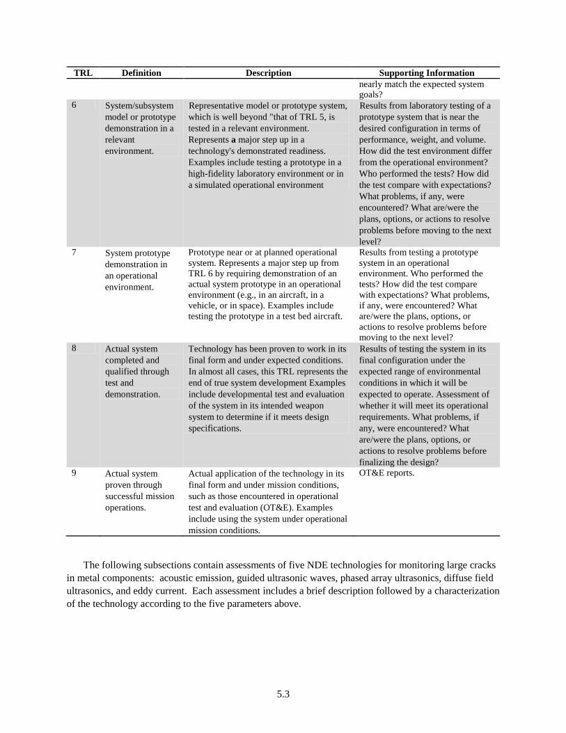
5.3
TRL Definition Description Supporting Information nearly match the expected system goals?
6 System/subsystem model or prototype demonstration in a relevant environment.
Representative model or prototype system, which is well beyond "that of TRL 5, is tested in a relevant environment. Represents a major step up in a technology's demonstrated readiness. Examples include testing a prototype in a high-fidelity laboratory environment or in a simulated operational environment
Results from laboratory testing of a prototype system that is near the desired configuration in terms of performance, weight, and volume. How did the test environment differ from the operational environment? Who performed the tests? How did the test compare with expectations? What problems, if any, were encountered? What are/were the plans, options, or actions to resolve problems before moving to the next level?
7 System prototype demonstration in an operational environment.
Prototype near or at planned operational system. Represents a major step up from TRL 6 by requiring demonstration of an actual system prototype in an operational environment (e.g., in an aircraft, in a vehicle, or in space). Examples include testing the prototype in a test bed aircraft.
Results from testing a prototype system in an operational environment. Who performed the tests? How did the test compare with expectations? What problems, if any, were encountered? What are/were the plans, options, or actions to resolve problems before moving to the next level?
8 Actual system completed and qualified through test and demonstration.
Technology has been proven to work in its final form and under expected conditions. In almost all cases, this TRL represents the end of true system development Examples include developmental test and evaluation of the system in its intended weapon system to determine if it meets design specifications.
Results of testing the system in its final configuration under the expected range of environmental conditions in which it will be expected to operate. Assessment of whether it will meet its operational requirements. What problems, if any, were encountered? What are/were the plans, options, or actions to resolve problems before finalizing the design?
9 Actual system proven through successful mission operations.
Actual application of the technology in its final form and under mission conditions, such as those encountered in operational test and evaluation (OT&E). Examples include using the system under operational mission conditions.
OT&E reports.
The following subsections contain assessments of five NDE technologies for monitoring large cracks in metal components: acoustic emission, guided ultrasonic waves, phased array ultrasonics, diffuse field ultrasonics, and eddy current. Each assessment includes a brief description followed by a characterization of the technology according to the five parameters above.
5.4
5.1.1 Acoustic Emission
Description – A detailed history and introduction to acoustic emission testing is provided in the American Society of Nondestructive Testing (ASNT) Handbook (ASNT 2005). Fundamentally, acoustic emission is the elastic energy released during deformation of materials (ASNT 2005). The released energy travels as a transient elastic wave in the material and is typically recorded using a transducer that is located at some distance from the AE source. In metals, several phenomena give rise to AE, including crack initiation and growth, phase transformations, twinning, deformation, etc. Factors such as leaks also give rise to changes in the local stress gradients, resulting in a transient elastic wave.
Maturity – AE is sanctioned by the ASME Code for non–through-wall crack growth monitoring in NPPs. The use of AE for crack growth monitoring has been demonstrated in the field on Limerick Unit 1 reactor (Hutton et al. 1993) and the technology to perform crack growth monitoring using AE is commercially available. The demonstration at Limerick Unit 1 was performed on a flaw in an RPV nozzle to safe-end weld performing successfully for one fuel cycle. Some of the sensors failed during the second fuel cycle due to thermal exposure. AE has not been demonstrated for monitoring crack growth on components inside of the RPV. Based on the above information, the maturity of AE for monitoring the growth of non–through-wall cracks in metal pressure boundary components of NPPs is assessed at TRL 8–9.
Measurement frequency – AE is a passive monitoring technique that is sensitive to the dynamic nature of degradation processes and is therefore a continuous monitoring technique.
Sensitivity – Crack propagation is physically characterized as a series of discrete jumps of length Δl. The length of the crack jump is determined by the size of the plastic zone at the crack tip that undergoes work hardening until the local stress intensity factor exceeds a threshold value, ΔKth. It is reported that 100 µm represents a typical value for Δl (Rogers 2005). During fatigue testing of flat Incoloy 901 test specimens, minimum detectable crack lengths between 50–100 µm were observed (Berkovits and Fang 1995). AE monitoring was used to investigate IGSCC growth in Inconel 600. The reported minimum detectable crack size from AE monitoring is 200 to 400 µm in length and 100 µm in depth (Sung et al. 1997). This agrees well with the result of IGSCC crack initiation studies in 304 stainless steel. In these studies, the minimum detectable crack dimensions are reported as 200–300 µm in length and 100–200 µm in depth (Jones et al. 1991). Minimum detectable crack growth rates of 10-7 m/s for IGSCC in Inconel 600 steel (Sung et al. 1997) and 2.33×10⁻⁸ m/s for TGSCC in 316 stainless steel have been reported (Shaira et al. 2008).
Flaw characterization capability – Crack growth rates can be estimated from AE activity assuming the specific emission activity, γ, is known. AE monitoring will be more responsive to flaw growth in materials with higher γ. However, γ varies considerably with material and component geometry (Sinclair et al. 1977) and the application of general formulas will result in estimates with great uncertainty. Appendix I of Article 13 of Section V of the ASME Code provides a general relationship for quantitative crack growth estimation in NPP components:
da/dt = 290(dN/dt)0.53, (5.1)

5.5
where da/dt is crack growth in microinches/second and dN/dt represents AE activity in events/second. The estimations obtained from using this formula are conservative and cannot be relied upon to provide highly accurate estimations of flaw growth.
Crack growth rates could also be estimated using localization algorithms incorporated in modern AE systems to locate the origin of AE activity using an array of sensors (see Figure 5.1). In the plane of the sensor array, the identified location of a source of AE activity will have an uncertainty at least as great as the thickness of the component under test. This can inhibit accurate sizing of small flaws that do not pose a significant threat to the structural integrity of a component. Figure 5.1 also indicates that is possible to ascertain the general orientation of planar flaws that are longer than the thickness of the component under test.
Figure 5.1. Plot Showing the Origin of AE Signals (red dots) Relative to an Array of AE Sensors (green)
Determination of the degradation process can be achieved by analyzing collected AE data. Cluster analysis of AE signals is performed by analyzing histograms or scatter plots of AE signals with respect to one or more signal features. This analysis is based on different processes resulting in unique distributions of signals. Discrimination of AE sources based on amplitude distributions represents a common signal analysis strategy. The amplitude distributions of individual sources of AE are assumed to exhibit a power law shape described by Sung et al. (1997):
( ) ( ) bthreshF V V V .−= (5.2)
F(V) is a cumulative distribution function representing the probability that a signal amplitude exceeds V. Vthresh is selected such that F(Vthresh) = 1. This method is based on the assumption that different sources of AE will exhibit unique b-coefficient values.

5.6
Figure 5.2. Example of an Amplitude Distribution Obtained from the Collection of AE Signals
Methods to automatically cluster and classify signals include K-means (Ramadan et al. 2008; Shaira et al. 2008) principle component analysis (Ramadan et al. 2008), and neural networks (Barga et al. 1990).
Accessibility – Geometric accessibility is not expected to be a major obstacle to AE monitor. An array of AE sensors can be mounted to a component using pressure-coupled or magnetic-clamping mechanisms. The exact array configuration could be modified to avoid geometric incompatibilities. AE sensors are susceptible to degradation due to extreme environments including high temperatures or high levels of radiation. AE waveguides can be used to isolate sensitive AE monitoring equipment from extreme environments at the expense of some sensitivity.
5.1.2 Guided Ultrasonic Waves
Description – Guided ultrasonic wave (GUW) monitoring is an active mode of monitoring as opposed to acoustic emission. GUW monitoring involves the introduction of energy into a component and observing reflections of that energy from flaws or other material discontinuities. GUW involves the introduction of ultrasonic waves with wavelengths on the same order of magnitude as the dimension of the component under inspection. As a consequence, boundary conditions significantly influence the propagation of GUW energy. In this scenario, the component under inspection supports the propagation of several GUW modes. Each of these modes experience dispersion that can result in significant variation of phase and group velocity (Vp and Vg, respectively) with respect to frequency. More complete and rigorous discussions regarding GUW can be found in multiple texts (Rose 1999; Cheeke 2002).
Maturity – GUW is a rapidly emerging inspection technology. Sensors for GUW inspections may be based on piezoelectric elements, magnetostrictive sensors (MsS), electromagnetic acoustic transducers (EMATs) (Shivaraj et al. 2008), or laser-based techniques (Yang et al. 2011). The possible applications of guided waves to piping and vessel inspections in the chemical, petrochemical, and power industries are numerous and varied. Commercial systems have been developed for corrosion detection using

5.7
circumferentially guided waves injected by EMATs and axial detection systems for long-range piping inspection (Cawley et al. 2003). With regard to nuclear power applications, GUW has been explored as a tool for inspecting heat exchangers (Vinogradov and Kidd 2006), fuel cladding (Kwun et al. 2009), free containment liner plates (Maxfield and Kuramoto 1988; Kwun 1999), embedded containment liner plates (Kwun and Kim 2000), and feedwater lines in pressurized heavy water reactors. However, GUW systems have not been demonstrated inside of an LWR containment during operation. The maturity of GUW for online monitoring of cracks in pressure boundary components of LWRs is assessed at TRL 4.
Measurement frequency – A pulse-echo based system will require 200 ms for signal propagation if group velocity is conservatively assumed to be 1000 m/s and a bounding limit of 100 m is assumed for inspectable pipe length. Additional time will be required to perform automatic signal processing. This measurement frequency may be considered continuous for the purposes of managing most forms of age-induced degradation in metal components.
Sensitivity – The sensitivity of GUW to gross material deformation is wavelength (λ) dependent. Sensitivity to degradation is greatest when λ ~ ℓ, where ℓ is the dimension of the flaw. By the definition of guided waves, λ ~ d, where d is the dimension of the component under test. Therefore, it’s anticipated that GUW is only sensitive to relatively large flaws. For instance, the sensitivity of a long-range corrosion monitoring technique developed for piping is sensitive to processes that result in 5%–10% removal of wall material (Alleyne et al. 1998; Lowe et al. 1998; Alleyne et al. 2001). Sensitivity to sharp discontinuities with dimensions shorter than the wavelength may be feasible. Computational studies of the reflection of cylindrically guided waves from axially oriented defects in pipe walls has been investigated by Valle et al. (2001). These studies showed that crack lengths down to 300 µm could be detected with transducers at a center frequency of 500 kHz and with high-frequency components extending up to 1.5 MHz. Further, it is typically feasible to operate at higher frequencies and obtain better spatial resolution using wave modes restricted to the surface of a component than in the bulk of the component. However, the inspection is only sensitive to those flaws that penetrate the surface and is not sensitive to the depth dimension of the flaw (Shivaraj et al. 2008).
Flaw characterization capability – GUW has been demonstrated to be effective at detecting and locating large defects in metallic components such as pipes, tubes, and plates. Characterization of defects using GUW is an active area of research and these efforts typically try to relate the reflection coefficient to the geometry of the material discontinuity at the defect. An extensive parametric study of the influence of several relevant parameters on the reflection of guided waves from notch defects was performed by Demma et al. (2004). These investigators looked at the effects of the notch dimensions in the axial, circumferential, and depth directions on the observed reflection coefficients for two axisymmetric modes [T(0,1) (torsional) and L(0,2) (longitudinal)] at low frequencies (10 kHz–65 kHz). In addition, the impact of notch location, pipe diameter, and wall thickness on the reflection coefficient for these two modes was considered. This particular technique was developed for long-range pipe inspections and was found to be sensitive to defects that resulted in the removal of 5%–10% of pipe material at the defect location. Monotonic increasing trends in the reflection coefficients were observed as each notch dimension increased in size. The circumferential extent of the notches could be estimated based on mode conversion to flexural modes due to reflections from non-axisymmetric defects. The circumferential extent of the defect can be estimated by taking the ratio of the amplitude of the reflection coefficient for axisymmetric mode to the amplitude of the reflection coefficient of the flexural mode. This method exhibits low sensitivity at low circumferential extent; thus, it may be difficult to distinguish a defect of 5% circumferential extent (normalized to full pipe circumference) from a defect of 10% circumferential
5.8
extent. The axial extent of the defect has little impact on the amplitude of the reflection coefficient if the flaw is 100% through wall. For partial through-wall defects, the amplitude of the reflection coefficient varies cyclically as the axial extent of the defect increases. This is due to interference caused by reflections from the back and front surfaces of the notch. This interference could potentially prevent the detection of a defect that actually exists. This is considered unlikely in practice, however, as transducers have finite bandwidths and inspections are normally performed at multiple frequencies. Finally, it is noted that defects that are of partial through-wall and partial circumferential extent introduce some ambiguity as it is difficult to determine how much each dimension is contributing to the reflection coefficient. Observations of flexural mode signals can help estimate the circumferential extent. A similar study has been performed to study the reflection of SH0 mode signals from notches in plates (Demma et al. 2004). This study was performed numerically using finite element (FE) modeling and mode decomposition techniques. Reflection coefficients for circumferentially guided waves reflected from axial cracks in a half cylinder were computed numerically by Valle et al. (2001). The results of these simulations indicated a quasi-linear relationship between the amplitude of the reflection coefficient and the length of the crack. In all of the numerical efforts above, information regarding flaw orientation and geometry is known a priori. The difficulty in trying to simultaneously size and determine the orientation of defects was highlighted in an experimental demonstration of guided waves to detect and locate defects in mockup fuel rod cladding specimens with fabricated defects (Kwun et al. 2009). MsS transducers were used to stimulate the T(0,1) mode. In this case, the intensity of the reflected signal was dependent on both size and orientation (axial, circumferential, 45°) of the defect. Independent sizing and determination of orientation was not possible (Kwun et al. 2009).
Accessibility – Comb or ring transducers require full 360° access for piping inspections. However, the long-range inspection capability permits the location of GUW transducers at convenient locations.
5.1.3 Phased-Array Ultrasonic Testing (PA-UT)
Conventional ultrasonic inspections employ the use of monolithic transducers in the frequency range of 2.25–5 MHz mounted on an angular wedge to generate longitudinal and transverse waves (Satyanarayan et al. 2009). To obtain an image of a flaw, the transducer is scanned over the surface automatically or manually. The PA-UT technique is a more advanced form of ultrasonic inspection in which beam steering and control is performed automatically by adjusting the phase delays (also known as focus laws) to elements of a linear or 2-D array, eliminating the need to physically scan the probe over the surface of a component for the purpose of flaw characterization. A subset of elements can be excited at once (referred to as the aperture) or elements can be excited individually. Line scanning is a mode of operation that refers to the sequential firing of individual elements to simulate single element scanning (Satyanarayan et al. 2009) except with much greater speed and consistency than could be achieved by scanning a single monolithic transducer. Common defect sizing and characterization algorithms are based on amplitude analysis and time-of-flight analysis [e.g., time-of-flight diffraction (TOFD)]. The Synthetic Aperture Focusing Technique (SAFT) is a technique borrowed from radar and sonar to improve lateral resolution and image contrast through reduction of backscatter. Due to the superior imaging quality of PA-UT over conventional UT, several applications of PA-UT to the inspection of LWR components have been explored. Example applications include the inspection cast austenitic stainless steel metal components (Anderson et al. 2008), steam turbines (Ciorau 2004), BWR core shrouds, and control rod drive mechanism tube nozzles (Komura et al. 2001). PA-UT inspection systems have been developed for high-temperature applications including viewing under the sodium coolant of liquid sodium-cooled fast

5.9
reactors. PA-UT probes have been developed to operate at temperatures of 220°C, which is the temperature the sodium is maintained at during shutdown to prevent solidification (Karasawa et al. 2000).
Maturity – Key hardware elements of a PA-UT system include the array probe, signal cables, data acquisition hardware, and the computer interface shown in Figures 5.3 and 5.4. PA-UT systems are commercially available from several technology vendors (Drinkwater and Wilcox 2006). Methodology for performing PA-UT inspections is outlined in Mandatory Appendixes IV and V of Article 4 of Section V of the ASME Boiler and Pressure Vessel Code. However, PA-UT systems have not been deployed for on-line inspections of LWR components and PA-UT technology has not been demonstrated at temperatures relevant to the primary coolant (near 300°C). The maturity of PA-UT technology for crack monitoring in metal pressure boundary components of NPPs is assessed to TRL 4-5.
Measurement frequency – The inspection speed depends on the amount of required scanning thus depending on the size of component being scanned.
Sensitivity – Minimum detectable crack depths are on the order of wavelength and reported to be approximately 0.5 mm (7.5 MHz) for practical applications (Moles 2004; Bond et al. 2011a).
Flaw characterization capability – PA-UT can effectively image flaws by employing signal processing algorithms such as SAFT and recording of PA-UT scan coordinates. A review of ultrasonic sizing studies by Moles (2004) concludes that the sizing accuracy of UT techniques is approximately ±1 mm.
Accessibility – Figure 5.4 shows that the footprint of PA-UT probes is significant (~ 8 cm) as well as its height. Difficulties can be encountered with scanning over uneven surfaces (near welds).
Figure 5.3. Photograph of Data Acquisition Hardware for PA-UT and Integration with Computer
Interface

5.10
Figure 5.4. Photograph of PA-UT Probe
5.1.4 Diffuse Ultrasonic Wave Fields (DUW)
Description – DUW is described as an inspection technique in which wave modes of all propagation directions and frequencies are excited with random amplitudes that are independent to each other and random phases that are uniformly distributed. Diffuse fields can be set up in fluids with random solid inclusions or heterogeneous solids. Diffuse fields can also form after many reflections from the boundaries of a structural component. The diffuse field develops over a time period that is long with respect to the time required for ultrasonic signals to travel the dimension of the test structure and entire components can be monitored with a sparse array of sensors (Lu 2007). As a consequence of the numerous mode directions, frequencies, and boundary reflections, direct assessment of structural condition from signals is not possible but detection of defects can be achieved by comparison to baseline signals. In addition, DUW signals are sensitive to environmental factors such as temperature and surface conditions (Lu and Michaels 2005). An advantage of DUW is that it can be applied to the inspection of complex component geometries.
Maturity – Diffuse ultrasonic wave fields are currently limited to laboratory testing. Some of the active areas of research include the development of methodologies to compensate for the influence of environmental factors on measurements and algorithms for signal processing (Lu 2007). Diffuse ultrasonic wave fields have not been demonstrated in environments of relevance to monitoring inside of an LWR containment. The maturity of diffuse ultrasonic wave fields is assessed at TRL 2-3.
Measurement frequency – Unlike guided waves, diffuse ultrasonic waves are formed after multiple reflections from the structural boundaries. In Weaver (1984), it is indicated that more than 50 boundary reflections may be required before the field becomes sufficiently diffuse. Thus, the time required to perform a DUW inspection will exceed GUW inspections by a factor of 25 assuming pulse-echo implementation of GUW testing. Based on the estimate for GUW inspection time in Section 5.1.2, approximately 5 s would be required to perform a DUW inspection on an equivalent component.

5.11
Sensitivity – DUW has been investigated in the laboratory using commercial longitudinal piezoelectric transducers to investigate fabricated defects in 2-in. × 6-in. × 0.25-in. rectangular specimens (Lu and Michaels 2005). The smallest flaw size that was consistently detected was a notch that was 1.27 mm (0.05 in) in length. The technique employed a novel methodology for temperature compensation that relied on an array of baseline signals obtained at representative temperatures over the expected operating range. The POD was observed to significantly decrease when a sparse array of baseline signals was provided for temperature compensation and the minimum detectable flaw size increased notably (Lu and Michaels 2005). Environmental effects including surface conditions and temperature have a notable influence on DUW signals. Specifically, Weaver and Lobkis (2001) have shown that temperature changes result in time dilation or compression of the signal.
Flaw characterization ability – DUW signals are difficult to simulate and model due to the numerous modes, frequencies, and boundary reflections represented by the signal. The complexity precludes solution to the inverse problem but damage assessment is possible by computing the correlation between the flawed specimen and an unflawed baseline specimen (Lu and Michaels 2005). However, complete characterization of type, size, and orientation of the defect is not possible without prior knowledge of the degradation characteristics.
Accessibility – Requires access for two or more longitudinal transducers approximately 0.5 in. in diameter (Lu and Michaels 2005).
5.1.5 Eddy Current Testing (ET)
Description – ET can measure changes in the electromagnetic properties near the surface of a material that are caused by damage. A coil, excited with an alternating current at a specific frequency, is used to induce eddy currents in accordance with Lenz’s law (ASNT 2004), in the specimen under test. The corresponding induced magnetic flux density changes the net magnetic flux linked with the coil, resulting in a change in its inductance. At the same time, losses due to the induced currents in the specimen manifest themselves as an increase in the resistance of the coil. Thus, the coil will present a change in electric impedance (relative to its impedance in air) when placed near a conducting specimen.
ET is limited in inspecting material within a skin depth of the surface. The technique is sanctioned by Section XI of the ASME Code for surface examinations. For the inspection of thin-walled material such as steam generator tubing, inspections are effectively volumetric.
Maturity – ET inspections are routinely employed to inspect damage to steam generator tubes during outages. These technologies include the use of bobbin coils, magnetic rotating pancake coils, and array probes (IAEA 1997; EPRI 2002). These probes perform inspections from the inner diameter of drained steam generator tubes. To the author’s knowledge, ET instruments for performing online inspections have not been developed. ET for performing online inspections of steam generator tubing is assessed at TRL 4.
Sensitivity – ET is only sensitive to defects less than 1 mm in size (Bond et al. 2011a).
Accessibility – Online ET monitoring of steam generator tubes will require the implementation of outer diameter probes. Mechanical scanning will be required to perform inspections over significant portions of material. Difficulties will be encountered in accessing defects located near supports.

5.12
5.2 Assessment of Technologies to Monitor Cable Degradation
The two cable monitoring technologies assessed in this section include time domain reflectometry and line resonance analysis.
5.2.1 Time Domain Reflectometry (TDR)
Description – Time domain reflectometry operates on the same principles as radar. A pulse of energy is transmitted down a cable from one end, which must be disconnected from the system for testing, and is reflected back when it encounters any change in electrical impedance along the cable. These changes may be due to the far end of the cable or faults and degradation along the length of the cable. The time necessary for the pulse to travel to the impedance change and reflect back to the open end of the cable can be used to determine the location of the impedance change. TDR can be used to identify the location and severity of electrical or insulation faults and the presence and location of water. TDR is applicable to low- and medium-voltage cables, as well as cable insulation and jackets of all types. The pulse used to detect faults is very low power and non-destructive to the cables being investigated.
Maturity –TDR is the most popular and effective cable testing technique in use for the evaluation of nuclear instrumentation system cables in NPPs (IEC 2010). Based on the widespread use of TDR, it is assess at TRL 9.
Measurement Frequency – This testing method requires that the end terminations of the cable be disconnected to perform the test. The test cannot be performed continuously or online.
Sensitivity – TDR technique effectively detects local and significant defects, but is less effective for minor anomalies (IEC 2010).
Flaw characterization capability – TDR provides useful information for identifying and locating potential defects and discontinuities in a cable. These measurements can identify the location and magnitude of an impedance change; however, this requires accurate baseline data for comparisons. When appropriately applied, TDR is able to identify changes in cable impedance due to loose connections, moisture, and cracks in cable conductors, connectors, and insulation. Transient conditions, such as immersion, will only be detected if they are present during testing.
Accessibility – TDR can be applied to cables in inaccessible locations, which are not available for visual inspection and other physical tests.
5.2.2 Line Resonance Analysis (LIRA)
Description – Line resonance analysis analyzes electrical test signals from a waveform generator by modeling the cable's wire system using transmission line theory. Through narrow-band frequency domain analysis of high frequency resonance effects, LIRA can be used to detect local or global changes in the electrical properties of a cable, which may result from insulation faults or degradation. The cumulative phase shift of the input impedance gives a condition indicator for aging and small defects, while amplitude changes account for larger effects. Because LIRA tests can detect small changes in the electrical properties in insulation materials, localized and bulk thermal aging can be detected and identified well before significant physical deterioration occurs.

5.13
Maturity –LIRA was developed at Halden Reactor Project from 2003–2005, and then further developed by Wirescan AS. LIRA has been tested extensively with low, medium, and high voltage cables, both in laboratory tests and in-situ experiments. Work with EPRI from 2006–2007 tested the capabilities of LIRA to identify cuts, gouges, and thermal aging in cables. However, it does not seem to be widely in use in NPPs; LIRA is assessed at TRL 8.
Measurement Frequency – Unlike TDR, LIRA can be performed in situ without disconnecting the cable. LIRA can be performed online by accounting for the effects of loads attached to the cable during the results analysis (Fantoni and Toman 2006). However, LIRA would likely be employed as a periodic test, which would allow for trending of degradation severity.
Sensitivity – LIRA is reported to detect changes in the electrical properties of insulation materials on the order of 1 pf (Fantoni 2010).
Flaw characterization capability – LIRA can detect thermally induced embrittlement and cracking, radiation-induced embrittlement and cracking, and severe mechanical damage. Results of tests with EPRI indicate that LIRA can identify cuts and gouges in the insulation system and thermal and radiation damage. LIRA can also be used to identify the location of faults.
Accessibility – LIRA tests are run in situ without disconnecting cables; it should be able to monitor cables in inaccessible locations.
5.3 Technologies Sensitive to Early Degradation in Metals (Precursor Monitoring)
Early degradation refers to a level of distress in a material that is insufficient to result in gross deformation, tearing, or material loss. Instead the degradation is manifest as a change in residual stresses, grain morphology, or bulk material properties (i.e., electromagnetic and elastic). The process of crack initiation may result in distress confined to a localized area while embrittlement damage (radiation and thermal-induced) may exist over a wider region. Unlike many NDE technologies for detection and monitoring of cracks, most NDE technologies for early degradation have not been demonstrated in the field. The following subsections contain discussions of several precursor monitoring technologies with potential application to monitoring in LWRs. Technologies discussed include nonlinear acoustics, acousto-ultrasonics, magnetic Barkhausen, and magnetic loop measurements. Several other techniques are briefly mentioned.
5.3.1 Nonlinear Acoustics
Conventional ultrasonic evaluation of materials is performed in the linear regime. This regime applies to the propagation of low-intensity ultrasonic waves such that deviations from the equilibrium state of the material caused by these signals is assumed to be small and material assessments are based on observing small changes in several parameters (e.g., velocity, attenuation, phase shifts, reflection and transmission coefficients) (Jhang 2009). The application of high-intensity ultrasonic energy into a structure can result in many nonlinear effects caused by nonlinear elasticity of the material or contact nonlinearities. The most relevant form of nonlinearity to the study of early degradation detection in materials is higher harmonic generation resulting from nonlinear elasticity in materials. Through this phenomenon, the existence and characteristics of defects are related and interpreted through an acoustic

5.14
signal at different frequency than input signal. The nonlinear 3rd order elastic constants of solids were first measured in the early 1960s and the harmonic generation of bulk waves was reported by several investigators (Carr 1964; Parker Jr. et al. 1964). Normally, the nonlinear effect of 3rd and higher order harmonics are much smaller than the effect of the 2nd order harmonic. Thus, the 2nd order harmonic has assumed special significance and its magnitude is represented by the nonlinear parameter, β. The magnitude of β is based on material properties and the degradation of elastic material properties can be monitored using this parameter (Jhang 2009).
The nonlinear acoustic parameter, β, is sensitive to fatigue damage because the distribution of dislocations during fatigue damage is known to cause significant changes in the material’s non-linear elastic wave behavior and manifests itself in harmonic generation (Jhang 2009). In Kulkarni et al. (2006), the nonlinear parameter is used to quantify pre-macro crack damage and forms the basis of a probabilistic model to predict the initiation of fatigue cracks. The nonlinear parameter has also formed the basis of fatigue life prediction in a rod specimen subject to bending fatigue. In this case, surface-shear waves were introduced into the specimen using EMAT transducers and nonlinear parameter responses were correlated with crack nucleation and extension (Ogi et al. 2001). In addition to mechanical fatigue damage, the sensitivity of the nonlinear parameter to precipitate hardening in ASTM A710 steel (Hurley et al. 2000), thermal aging of 2.25Cr-1Mo steel (Choi et al. 2002), and creep damage in CrMoV rotor steels (Park et al. 2003) has been explored. The nonlinear response of materials is most frequently investigated for excitation with bulk waves, but it is noted that nonlinear effects in surface waves and guided waves could potentially form the basis of a material damage assessment. Nonlinearities in surface acoustic waves have been used to investigate damage in Ti-6Al-4V and Inconel 718 (Barnard et al. 2003), nickel based superalloy (Hermann et al. 2006), aluminum alloy 2024 and 6061 (Shui et al. 2008).
5.3.2 Acousto-ultrasonics (AU)
Acousto-ultrasonics (AU) is an NDE method that is closely related to diffuse ultrasonic wave field inspections (Lu 2007). AU was developed in an attempt to enhance the passive AE inspection technique by combining passive and active modes of inspection. The AU technique employs one transducer for excitation and one transducer for signal reception. It is noted that AU is not sensitive to discrete defects but can sense distributed damage resulting in localized changes to elastic properties of the material. The receiver does not sense the excitation signal, but rather the response of the structure to the acoustic disturbance (Lu 2007). The AU technique is often attributed to Vary (1982) and was developed primarily for the inspection of composite materials. According to Vary (1991),
“Acousto-ultrasonics assesses integrated defect states and the resultant variations in properties such as tensile, shear, and flexural strengths and fracture resistance. Matrix cure state, porosity, fiber orientation, fiber volume fraction, fiber-matrix bonding, and interlaminar bond quality are factors that underlie acousto-ultrasonic evaluations.”
The response of a structure to AU can be based on the evaluation of several AU signal features including ultrasonic decay rate, mean time, skew factor, and the power spectrum (Kautz 2002). The evaluation of the response must be compared to a baseline or unflawed state to perform an assessment of component damage. This is a disadvantage because of the burden necessitated by the collection and maintenance of a library of baseline data and data representative of several states of degradation. An advantage of this approach to assessing damage is that the assessment can be performed without specific knowledge of the interaction between the probing energy and the boundaries of the component. Thus,

5.15
AU may be used to assess the state of components with complex geometries such as nozzles, elbows, and pump casings.
5.3.3 Magnetic Barkhausen Emission (MBE)
The magnetic Barkhausen emission of a material is measured by applying a continuously time-varying magnetic field to the material and observing the induced flux in a coil placed nearby. More specifically, MBE is characterized by discontinuous changes in flux even in the presence of a continuous excitation signal. The theory behind this behavior relates observed flux changes to the stochastic processes of magnetic domain wall motion and rotation (Jiles 2000). Magnetic domain walls respond to the application of external field by trying to align with the direction of the external field and experience deformation. The deformation is caused by resistance to the domain wall motion and rotation due to domain wall pinning. Pinning sites can be described as microscopic inhomogeneous volumes of material including dislocations, second phase precipitates, and voids. Under low external field intensities, this deformation is elastic and reversible. As the field intensity continues to increase, the domain wall eventually breaks away from the pinning site resulting in rapid and irreversible motion, which is expressed as a discontinuity in the rate of change of magnetization with time (Jiles 2000).
The inherent connection between MBE activity and micro structural features of a material has motivated numerous studies of its ability to nondestructively sense material damage at the micro structural level. In 9Cr-1Mo steel, the formation of carbides like M23C6, Laves phase (Fe2Mo), and Z-phase cause creep failure. The increase in MBE from the second stage of creep in 9Cr-1Mo has been attributed to the growth of those second phases (Mitra et al. 2007). The MBE response to low cycle fatigue (LCF) has also been studied in 9Cr-1Mo material and the response increased during phases associated with hardening and subsequent softening. The MBE response leveled off during a stage associated with stabilization of the dislocation structure and then increased sharply in response to crack initiation and propagation (Moorthy et al. 1999). The MBE response to α’-martensite formation from LCF in 304L stainless steel has also been a subject of investigation (Vincent et al. 2005). The MBE response from α’-martensite was clearly distinguishable from δ-ferrite and the MBE from cold rolling was stronger than in response to LCF. For LCF, the MBE response was greater during tensile loading than compressional loading. The plastic deformation around a pit in ASTM 36 steel samples has been measured with MBE and compared with FE models of ideal plastic deformation and parameters from the MBE data were extracted to detect the plastic deformation and measure the pit width (Perez-Benitez et al. 2008). Residual stresses in AS1548-7-460R steel have been investigated using MBE measurements. The MBE signals displayed symmetry with respect to tensile and compressive stresses showing more sensitivity to compression. Welded plates of the same material were also studied and a sharp change in the MBE response was observed at the weld edge indicating stress concentration (Stewart et al. 2004). The MBE response has been measured in the elastic-plastic stress region for the rolling and transversal directions of AISI/SAE 1070 annealed surfaces. The results indicate that the magnetic anisotropy coefficient can be used to characterize the linear and nonlinear elastic limits of material under tensile load (Campos et al. 2008). The effects of microstructure evolution from isothermal annealing on structure-sensitive magnetic properties on MBE in 12% CrMoV steel have been investigated and the MBE energy was correlated to three stages of microstructure evolution. The linear relationship between hardness and MBE parameters in the magnetization region of irreversible domain wall displacement suggest hardness and microstructural evolution could be evaluated nondestructively with MBE (Yi et al. 1994).

5.16
5.3.4 Magnetic Loop Parameters
The magnetic loop or hysteresis curve is a plot of the magnetic induction, B, as a function of applied magnetic field, H. Early degradation in a material can be assessed by the magnetic loop by relating magnetic loop parameters to certain microstructure trends associated with forms of damage. Magnetic loop parameters sensitive to microstructure changes include coercive force, Hc, residual induction, Br, hysteresis curve slope, saturation magnetization, Ms, and hysteresis curve area. Raj et al. (2003) provides a thorough assessment of the use of magnetic loop parameters for assessing damage from changes in microstructure. Magnetic loop parameters are assessed with respect to sensitivity to grain size, microstructure changes due to cold work, volume fraction of secondary ferritic phases in a paramagnetic material, and mechanical properties. In addition, the effectiveness of magnetic loop parameters at estimating creep and fatigue damage is considered. It is observed that the magnetic loop parameters are sensitive to α’-martensite phase formation and can detect it for 10% amount of cold work. Ms has been used to determine quantity of ferrite and martensite contents in duplex steels and transformation-induced plasticity steels (Mikheev and Gorkunov 1985) and residual austenite in carbon and low-alloy steels (Gorkunov 1991). However, Ms measurements require application of large field and precludes the use of this technique in practice. The relationship between magnetic loop parameters and mechanical properties is unique to specific classes of steels depending on amount of carbon and other alloying elements. Studies of creep on Cr-Mo steels showed lower remanence and higher Hc indicative of creep damage. The product of remanence and Hc also seems to be a good indicator of creep damage level. Magnetic loop parameters are unable to discern individual effects of multiple simultaneous microstructure evolution phenomena during creep.
5.3.5 Other Techniques
In addition to the techniques discussed above, numerous other NDE techniques exist for microstructure level assessments. Raj et al. (2003) provides a comprehensive review of NDE techniques sensitive to microstructure level responses to degradation. Bond et al. (2011a) provides an overview of possible damage assessment technologies for proactive management of materials degradation in LWRs. Damage assessment technologies are summarized and categorized with respect to applicability to the four stages of damage progression identified in Figure 3.1.
Inspections via positron annihilation are sensitive to electron density variations and voids. The tool has been used under laboratory settings to assess the void swelling phenomenon for Ti-modified stainless steel exposed ion beam irradiation (Amarendra et al. 2008; Davis et al. 2008; Arunkumar et al. 2009; Davis et al. 2009). The eventual transfer of positron annihilation to field is questionable, however, due to high levels of background radiation and applicability to core internal structures. X-ray diffraction and small angle neutron scattering (SANS) techniques face similar obstacles with respect to online deployment of the technologies in the field. SANS is shown to be sensitive to various microstructure features including grain boundaries, dislocations, precipitates, and voids (Raj et al. 2003). Seebeck coefficient (SC) measurements have been studied as a technique to assess the level of embrittlement in RPV steels (Niffenegger et al. 2005). SC measurements were obtained from several irradiated Charpy specimens of Japanese reference steel, JRQ. The samples were irradiated up to levels of 4×10¹⁹ n/cm2. Results from SC measurements exhibited a linear behavior with respect to the level of neutron exposure. The efficacy of this technique for in situ monitoring of RPV steel is less clear as large amounts of energy would be required to drive significant thermal gradients in the wall of the RPV.

5.17
5.4 Concrete
Multiple NDE technologies for assessing the health of concrete structures are described below. In particular, technologies are described for the detection of cracks in bulk members and for the inspection of metal hardware including reinforcing steel and prestressed tendons.
5.4.1 Ultrasonic Testing
Ultrasound transmits very little energy through air, facilitating the detection of surface cracks in concrete although cracks that are small or filled with liquids or debris may be difficult to detect (Malhotra and Carino 2004). A sophisticated approach to concrete inspection using ultrasonic techniques is embodied in the acoustic time travel tomography (ATTT) technique that was employed in the inspection of Barker Dam north of Boulder, Colorado (Bond et al. 2000; Kepler et al. 2000). The ATTT technique was able to detect most of the horizontally oriented defects along the face of the dam. A complete image of crack defect locations was obtained through the collection of signals at regularly spaced measurement locations.
The ultrasound velocity can also be correlated to the strength of the concrete and related to the modulus of elasticity, assuming the Poisson’s ratio and density are known. Pulse velocity measurements are significantly impacted by the presence of reinforcing steel as the velocity in the steel is 1.4 to 1.7 times the velocity in the concrete. The type and amount of aggregate also influences the pulse velocity and is generally higher in aggregate materials than in the cement paste (Malhotra and Carino 2004). It has been observed that ultrasonic pulse velocity and attenuation measurements are sensitive to concrete expansion and cracking caused by alkali-silica reactions (Shah and Hookham 1998).
5.4.2 Thermographic Imaging
The transport of heat through a concrete member is constrained along paths that intercept air pockets in the form of voids, delaminations, or cracks. Faults can be detected by viewing the surface of a concrete structure with an infrared imager and identifying regions of constrained heat flow. The best contrast is obtained when the rate of heat flow through the concrete is large. One advantage of this method is its ability to scan in two dimensions. Limitations of the method include its inability to determine the depth at which defects are located and to determine the thickness of the defects. Also, the method is sensitive to environmental conditions. Infrared thermography has been used for the inspection of bridge decks, airport taxi-ways, garage decks, swimming pools, and tunnel walls (Malhotra and Carino 2004).
5.4.3 Radiographic Testing
Gamma-rays can detect faults in concrete, as the attenuation of a gamma-ray beam is correlated to the density of the concrete member. They can be used for volumetric examination of concrete and are promising for probing containment walls, as they can penetrate relatively thick sections of concrete (up to 0.5 m). However, the inner wall of a concrete containment structure is often lined with metal plates and may not be accessible for detecting transmitted gamma rays. In addition, the extreme thickness of concrete containment walls (~ 1 m) is likely to cause excessive attenuation of the source gammas. Backscatter gamma-ray or x-ray measurements are advantageous because they only require access to one side of the containment wall. However, backscatter techniques are only sensitive to the first 3 inches of concrete beneath the exposed surface (Malhotra and Carino 2004). RT is less reliable at finding planar

5.18
flaws such as cracking, requires radiation protection, and must be carried out by properly licensed and certified individuals (Naus 2007).
5.4.4 Half-cell Potential and Surface Potential
Half-cell potential is an electrochemical potential measurement method that provides an indication if the reinforcing steel is susceptible to corrosion. This method is sensitive to the flow of electrons and build-up of negative potential in the reinforcing steel as a result of corrosion. These measurements can be obtained at patterned locations and a map of the measurements provides a convenient visualization of the potential at the surface of the concrete. Strong potential gradients indicate sites where localized anodes have formed and thus provide an indication of the susceptibility of the reinforcing steel to corrosion (Malhotra and Carino 2004). This technique is performed using a reference electrode to obtain measurements at the surface of the concrete relative to the potential of the reinforcing steel. Drawbacks to this technique are that the magnitude and rate of corrosion cannot be determined, the technique is sensitive to environmental effects, and direct access to the reinforcing steel is required.
Alternatively, a surface potential technique can be applied that utilizes two reference electrodes to map out the potential distribution on the surface of a concrete structure. In this case, one reference electrode remains stationary while the other electrode is movable. This method does not require direct access to the reinforcing steel (Song and Saraswathy 2007).
5.4.5 Polarization Resistance
The linear polarization resistance of concrete is inversely related to the corrosion current density and can provide an estimate of the instantaneous rate of corrosion (Malhotra and Carino 2004). The polarization resistance of steel reinforcement embedded in concrete is defined as the ratio between applied voltage and the step in current ∆I when the metal is slightly polarized from its free corrosion potential, Ecorr (Andrade and Alonso 2004). A relationship exists between the corrosion rate of the steel reinforcement in concrete and the polarization resistance. The corrosion rate is usually expressed as the corrosion current per unit area of bar (Naus 2007).
5.4.6 Microwave Techniques
Short pulse radar can be effective at detecting faults and reinforcing steel embedded in concrete structures. This method relies on the reflection of signals from the interface of regions with different dielectric properties. This method has been used for detecting the delamination of concrete in bridge decks, to estimate the water-to-cement ratio in fresh concrete, to estimate the thickness of concrete members from the two-way travel time of injected pulses, and to locate reinforcement steel. A serious limitation of this method is the sensitivity to embedded steel. Interfering signals from embedded steel can obscure weaker signals from cracks, delaminated regions, or voids, making them difficult to detect. The maximum penetration distance in dry, unreinforced concrete is approximately 24 in. (Malhotra and Carino 2004).
5.4.7 Other Techniques for Monitoring of Tendons and Reinforcing Steel
Several techniques have been investigated to detect relaxation of prestressed tendons in concrete containment structures non-invasively. Strain gauges have recently been implemented to perform online

5.19
monitoring of tendon stress at the Ginna nuclear power station (Lindberg 2011). GUWs have also been investigated to detect stress levels in prestressed tendons (Beard et al. 2003; Chaki and Bourse 2009). In the case of grouted tendons leakage into the embedding structure inhibits the inspection range (Beard et al. 2003). Nonlinear guided waves have been investigated as means to inspect prestressing tendons in bridges (Bartoli et al. 2009) and cylindrical guided waves have been investigated to detect delamination between corrugated reinforcing steel rods and the embedding concrete member (Miller 2010). AE has been investigated as a tool to detect corrosion in both reinforcing steel (Zdunek et al. 1995) and prestressing tendons (Ramadan et al. 2008).


6.1
6.0 Discussion/Technical Gaps
6.1 Critique of Technologies for Monitoring Crack Growth
AE is considered a rather mature technology for monitoring NPP components on-line due to the demonstration of the technique during operation of Limerick Unit 1 (Hutton et al. 1993). The system eventually failed due to thermal overexposure of some of the transducer elements. Currently, Section XI of the ASME Code limits AE to monitoring the growth of cracks that have already been sized using other NDE techniques. Issues that could inhibit the use of AE as a proactive monitoring tool for degradation of metallic components include environmental compatibility, susceptibility to interference from extraneous sources of noise, and accuracy.
For monitoring components of the reactor pressure boundary, modest effort is probably required to ensure long-term operation of AE sensors in an operating reactor environment. High temperature transducers available from commercial vendors are often rated up to 500°C and waveguides can be deployed to isolate transducers from the temperature of the monitored component. However, the application of high-temperature transducers or waveguides will result in a sensor with lower sensitivity. Efforts should focus on optimizing the tolerance of sensors for AE to high temperatures while minimizing the loss in sensitivity.
Appendix I of Article 13 of Section V of the ASME Code provides a formula for estimating crack growth rate from AE activity. This formula is general and conservative since flaw sizing is performed using alternative NDE techniques. A more accurate relationship is required if online monitoring using AE is to replace periodic NDE and if AE data is used for the purpose of predicting remaining useful life (RUL). This requires the application of formulas that are specific to the material and component under investigation.
The susceptibility of AE to coolant flow noise in NPPs has been mitigated in the past by filtering out low frequency signals (<200 kHz). While this can greatly improve performance, interference from other potential sources of extraneous noise could limit the effectiveness of AE monitoring. The use of wideband transducers would result in less signal distortion and may improve the ability to discriminate AE signals of interest from extraneous signals—at the expense of reduced sensitivity. Principal component analysis (PCA) has been investigated as a technique to distinguish AE signals (Ramadan et al. 2008; Shaira et al. 2008). The development and application of PCA and other sophisticated algorithms for AE signal analysis may reduce the susceptibility of AE to extraneous sources of signals and aid in characterization of the degradation mechanism.
GUW monitoring is attractive due to its ability to quickly perform long-range, large-volume inspections on NPP components. The complexity of signals limits the application primarily to simple geometries. GUW has not been demonstrated in an environment relevant to an operating LWR. High temperature is a concern for GUW applications and there is a need for high-temperature sensors for GUW applications. Alternatively, the long-range capability of the technique may allow the technique to monitor high-temperature components from a benign environment. In its present form, GUW is sensitive to gross forms of degradation. It can detect flaws but independent sizing and characterization remains an issue. The accuracy of guided wave sizing may not be sufficient to base RUL estimates. It is noted that it can be

6.2
difficult to distinguish a 5% circumferential flaw (percentage of full circumference) from a 10% circumferential flaw (Demma et al. 2004).
The diffuse field monitoring technique (DUW) is at a relatively immature state of development but is promising due to its potential for monitoring geometrically complex structures. The technique has been applied to the detection of flaws in 2-in. × 6-in. × 0.25-in. rectangular specimens and was sensitive to notches as small as 1.27 mm (Lu and Michaels 2005). The technique relies on multiple reflections of wave modes from the boundaries of the component under inspection so the feasibility of monitoring large structural NPP components is unclear. The impact of coolant flow noise on the sensitivity of the technique and the long-term reliability of the technique are also issues to consider in the application of this technique to online monitoring of NPPs.
The ability of PA-UT to rapidly inspect a defect from multiple angles allows the technique to accurately size and characterize many defects. The issues that present the biggest obstacles to implementation of PA-UT as an online monitoring technique include survivability and coupling at high temperature (near 300°C). Current PA-UT probes rely on water for coupling of signals into a component and the use of liquid couplant facilitates mechanical scanning. Water is not an option at 300°C, motivating the use of alternative means of coupling. The footprint of phased-array probes presents another issue ultimately limiting its application due to physical access limitations caused by uneven surfaces and inadequate clearance for the probe.
ET probes have routinely been deployed to perform inner-diameter inspections of steam generator tubes during outages. The application of ET probes for performing online inspections requires the development of probes that can tolerate high temperature (near 300°C) and a moist/steam environment. Further, online ET monitoring of steam generator tubes could not be performed from the tube inner diameter.
6.2 Critique of Technologies for Precursor Monitoring
The nonlinearity parameter, β, has shown sensitivity to pre-macro crack damage and has been used for RUL estimations of laboratory specimens. Continued efforts are needed to transfer the technology to the field and to explore the efficacy of the technique for tracking precursor signals related to other forms of damage in metals, such as SCC, embrittlement, creep, and corrosion. One difficulty with implementing this technique in the field is that a priori knowledge about the location of damage accumulation may not be known. A methodology is needed to determine when and where transducers should be placed for performing measurements of β of structural components in the field.
The AU technique was initially devised as a way to enhance the AE technique by actively stimulating signals from crack surfaces. The technique is described as being sensitive to the integrated health of a component rather than to individual discrete defects. It is sensitive to distributed parameters such as tensile, shear, and flexural strengths and fracture resistance. The sensitivity of AU to damage caused by radiation and thermal embrittlement may warrant further investigations and efforts to extract parameters that correlate to the significance of the damage. AU systems are commercially available but such systems would require additional hardening to tolerate the high temperature encountered with pressure boundary components.

6.3
MBE provides a signal that is directly correlated with microstructure level details. Contributions to domain wall behavior including grain size and precipitate density are expressed in the MBE signal. The sensitivity of MBE to the presence of secondary ferromagnetic phases make the technique a potential candidate for the detection of stress induced α’-martensite and δ-ferrite introduced by thermal aging. Many phenomena contribute to the MBE signal complicating the analysis. As a particular form of damage progresses, some phenomena may contribute to the signal while other phenomena may subtract from it. Efforts are needed to identify parameters from the MBE signal that show good correlation with damage significance (analogous to the nonlinearity parameter, β). Practical implementation of MBE will require the development of high-temperature probes and a methodology for identifying locations where crack precursor damage begins to accumulate. MBE could potentially be scanned over a larger area of interest to identify specific locations of concentrated precursor damage.
Magnetic loop measurements are less sensitive to phenomena at the microstructure level than MBE. However, magnetic loop parameters have expressed sensitivity to the quantity of secondary ferromagnetic phases in materials. The evolution of material phases as damage progresses from initiation to failure can be complex. As a consequence, the magnetic loop parameter may not exhibit monotonic behavior over the lifetime of the damage, inhibiting its ability to provide an unambiguous interpretation of damage significance. Magnetic loop measurements are obtained in the process of performing MBE measurements. Magnetic loop analysis can be combined with MBE to aid in interpretation of signals (Raj et al. 2003) and aid the interpretation of damage significance.
6.3 Critique of NDE Technologies for Assessment of Concrete Containment Structures
Most of the NDE technologies for assessing the health of concrete containment structures are mature and readily available for field deployment. Further, NDE tools for monitoring the containment structure will not be exposed to extreme high temperatures and further development in this direction is not needed. Several techniques have emerged for monitoring metal components (tendons and reinforcing steel). The demonstration of fiber-optic strain gauges for monitoring the Ginna containment structure shows new techniques can have an impact on the LTO of currently operating reactors. While tendons are accessible, reinforcing steel is generally not accessible. Therefore, it is not clear if guided wave and acoustic emission techniques can have an impact on LTO of LWRs. Techniques that can inspect the interior of as-built structures are needed. Basemats are difficult to inspect because they are heavily reinforced, very thick, and located beneath the RPV. Non-invasive techniques with significant penetration ability include radiographic and microwave-radar techniques. Radiographic techniques require access to both sides of a structure while radar-based techniques are limited by the presence of significant reinforcing steel.
6.4 Monitoring of Buried Piping
EPRI has investigated numerous technologies for the inspection of buried piping (EPRI 2008). Access to buried piping outer diameter is restricted due to contact with soil or concrete. Inner diameter inspections are also inhibited for long stretches of pipeline that consists of elbows, tees, or other sources of sharp redirection. GUW is considered one of the leading technologies for performing inspections of buried piping but is limited to inspections of a few 10’s of meters and also encounters difficulties with inspecting pipeline beyond elbows, tees, or other joints. Thus, full-length inspections of buried pipes with GUW would require excavation every 20–30 meters or beyond every elbow for placement of a GUW

6.4
probe. Alternatively, excavations could be performed at the site of a known indication to perform an assessment with other NDE techniques. Excavation may not be possible in all situations (buried piping routed beneath the reactor containment building).
6.5 General Technical Gaps
Several general technical gaps emerge from an assessment of NDE technologies for proactive management of aging degradation. They are:
• Environmentally rugged sensors are needed that can operate reliably for long periods at temperatures near 300°C. Sensors for monitoring RPV internal components will also need to be resistant to exposure by neutron radiation, and eddy current sensors deployed for online monitoring of steam generator tubes also need to be resistant to moisture and steam.
• Precursor NDE signal parameters that exhibit an unambiguous correlation with the level of pre-macro defect damage are needed for many forms of degradation relevant to LWRs. The nonlinearity parameter has exhibited good correlation with damage in fatigue specimens prior to cracking. Parameters with similar behavior are needed for SCC and embrittlement.
• The placement of sensors for precursor monitoring presents a challenge. Precursor monitoring technologies need to be able to regularly sample large volumes of material or rapidly scan a component to identify regions where damage exists in precursor state. The scanning can be limited to regions of anticipated damage initiation based on experience and or modeling/simulations.

7.1
7.0 Summary/Conclusions
Long-term operation (LTO) is used to describe the operation of NPPs into the 60–80-year timeframe. As NPPs enter this phase of their lifetime, aging issues considered irrelevant to the first 60 years of operation suddenly have significance. To ensure the continued safe operation of the current fleet of commercial NPPs in the United States, aging concerns that threaten continued plant operation must be addressed. In this regard, much of the focus is on passive SSCs as active SSCs are well managed and routinely repaired or replaced through maintenance programs while passive SSCs are addressed through periodic ISI and aging management programs.
ISI through periodic NDE is challenged by degradation mechanisms that exhibit long incubation periods followed by rapid growth to failure. In addition, licensees can expect the discovery of new forms of degradation as reactors enter the period of extended operation. Some of the issues considered as major concerns to limiting the extended operating lifetime of LWRs include SCC (mostly PWSCC of nickel alloy components and IASCC of reactor internals), radiation embrittlement of the RPV, degradation of concrete containment structures, degradation of buried pipes, and cable degradation.
The impact of the above aging degradation concerns for LWRs can be minimized by adopting a proactive approach to aging management. The proactive approach to aging management addresses degradation concerns before they become major issues and threaten to disrupt continued safe operation of the plant. Key elements of proactive aging management include frequent sampling of component degradation through implementation of online monitoring, early detection of degradation (degradation precursors), and the application of prognostics for RUL predictions.
Several NDE technologies are assessed with respect to potential integration into a proactive aging management plan. For RUL estimations, NDE measurements must allow appropriate characterization of degradation mechanisms so that the correct degradation models are applied. Further, useful RUL predictions require the current state of a component to be assessed with good accuracy. This accuracy requirement is transferred to NDE technologies which must be able to characterize flaw significance with high accuracy. To assist in the assessment of NDE technologies, they are classified as technologies for monitoring large cracks in metal components, technologies for monitoring cable degradation, technologies for monitoring early degradation (precursors), and technologies for monitoring concrete containment structures.
The assessment of NDE technologies for proactive aging management is performed to reveal technical gaps that could inhibit the implementation of proactive aging management strategies. While the assessment can reveal gaps specific to each individual technology, some general themes do emerge. General technical issues or gaps identified through this assessment are summarized below:
• Environmentally rugged sensors are needed that can operate reliably for long periods at temperatures near 300°C. Sensors for monitoring RPV internal components will also need to be resistant to exposure by neutron radiation, and eddy current sensors deployed for online monitoring of steam generator tubes also need to be resistant to moisture and steam.
• Precursor NDE signal parameters that exhibit an unambiguous correlation with the level of pre-macro defect damage are needed for many forms of degradation relevant to LWRs. The nonlinearity

7.2
parameter has exhibited good correlation with damage in fatigue specimens prior to cracking. Parameters with similar behavior are needed for SCC and embrittlement.
• The placement of sensors for precursor monitoring presents a challenge. Precursor monitoring technologies need to be able to regularly sample large volumes of material or rapidly scan a component to identify regions where damage exists in precursor state. The scanning can be limited to regions of anticipated damage initiation based on experience and or modeling/simulations.
In addition the general needs identified above, some more specific needs have been identified for technologies to monitor large cracks in metal components of the pressure boundary. These are provided for each technology below:
• Acoustic Emission (AE) – The formula contained in Appendix I of Article 13 of Section V of the ASME Code relating crack growth rate to AE activity is generalized and conservative. The accuracy provided by this formula is not sufficient to base predictions of RUL. Achieving the necessary accuracy to perform RUL predictions from AE data may require the formulation of component/material specific crack growth rate to AE activity relationships.
Currently, Section XI of the ASME Code sanctions the use of online monitoring with AE to supplement periodic NDE. In this application, AE is limited to monitoring the growth of existing flaws that have been sized using alternative NDE techniques. The detection of defects with AE must be verified with alternative NDE techniques. To experience the full advantages of proactive aging management, online monitoring with AE should replace periodic NDE. In this case, AE will be relied upon for accurate detection of new flaws and defects. To keep the false call probability low, sophisticated algorithms for signal discrimination should be developed.
AE sensors failed due to thermal exposure during an online monitoring demonstration at the Limerick Unit 1 generating station. Testing of modern AE equipment in equivalent environments is necessary to assess long-term reliability.
• Guided Ultrasonic Waves (GUW) – High temperature transducers for GUW monitoring need to be developed and validated with respect to long term reliability. Currently, the technique is unable to fully characterize a flaw without some prior knowledge regarding the state of the flaw. The sensitivity of the technique to anticipated forms of degradation in specific LWR components under operating conditions should be assessed.
• Diffuse Ultrasonic Wave Field (DUW) – DUW requires multiple reflections of injected energy from the boundaries of the component and has been tested on relatively small components. The feasibility of applying the technique on components and materials of interest to operating LWRs should be assessed. Further, the influence of reactor coolant noise on the performance of the technique should also be assessed.
• Phased Array Ultrasonic Testing (PA-UT) – PA-UT is mostly inhibited from online monitoring applications due to the high temperature environment. The high temperature environment also requires the use of coupling alternatives to water.
• Eddy Current Testing (ET) – Eddy current testing is mostly considered a surface examination technique except for the examination of thin wall tubing such as steam generator tubing. ET is routinely deployed for steam generator inspections during outages but online monitoring will require the development of techniques to perform ET inspections from tube outer diameters.

8.3
For concrete containments, thorough inspections of basemats are an issue. Inspection technologies are unable to penetrate the full thickness of the basemat which is heavily reinforced. Further, access to the soil side of the basemat is restricted.
8.0 References
10 CFR 50.61a. 2011. "Alternate Fracture Toughness Requirements for Protection Against Pressurized Thermal Shock Events." Code of Federal Regulations, U.S. Nuclear Regulatory Commission, Washington, D.C.
Alleyne DN, MJS Lowe and P Cawley. 1998. "The Reflection of Guided Waves From Circumferential Notches in Pipes." Journal of Applied Mechanics, Transactions ASME 65(3):635-641.
Alleyne DN, B Pavlakovic, MJS Lowe and P Cawley. 2001. "Rapid Long-Range Inspection of Chemical Plant Pipework Using Guided Waves." Insight: Non-Destructive Testing and Condition Monitoring 43(2):93-96.
Amarendra G, BK Panigraphi, S Abhaya, C Davis, R Rajaraman, KGM Nair, CS Sundar and B Raj. 2008. "Positron Beam Studies of Void Swelling in Ion Irradiated Ti-modified Stainless Steel." Applied Surface Science 255:139-141.
Anandakumaran K. 2007. "Aging and Condition Monitoring Studies of Composite Insulation Cables Used in Nuclear Power Plants." IEEE Transactions on Dielectrics and Electrical Insulation 14(1):227-237.
Anderson MT, SL Crawford, SE Cumblidge, AA Diaz and SR Doctor. 2008. "Low Frequency Phased Array Methods for Crack Detection in Cast Austenitic Piping Components." In Proceedings of the Sixth International Conference on NDE in Relation to Structural Integrity for Nuclear and Pressurised Components, EUR 23356 EN-2008, pp. 813-823. October 8-10, 2007, Budapest, Hungary. eds: M Bieth and J Whittle. European Communities.
Andrade C and C Alonso. 2004. "Test Method for On-site Corrosion Rate Measurement of Steel Reinforcement in Concrete by Means of the Polarisation Resistance Method, RILEM TC 154-EMC: Electrochemical Techniques for Measuring Metallic Corrosion." Materials and Structures 37:623-643.
Andresen PL, FP Ford, K Gott, RL Jones, PM Scott, T Shoji, RW Staehle and RL Tapping. 2007. Expert Panel Report on Proactive Materials Degradation Assessment. NUREG/CR-6923, BNL-NUREG-77111-2006, U.S. Nuclear Regulatory Commission, Washington, D.C.
Arunkumar J, S Abhaya, R Rajaraman, G Amarendra, KGM Nair, CS Sundar and B Raj. 2009. "Defect Recovery in Proton Irradiated Ti-modified Stainless Steel Probed by Positron Annihilation." Journal of Nuclear Materials 384:245-248.
ASME. 2007. 2007 ASME Boiler and Pressure Vessel Code, Section XI: Rules for Inservice Inspection of Nuclear Power Plant Components. American Society of Mechanical Engineers, New York.
8.2
ASNT. 2004. Nondestructive Testing Handbook, Third Edition: Volume 5, Electromagnetic Testing. SS Udpa and PO Moore, American Society for Nondestructive Testing, Columbus, Ohio.
ASNT. 2005. Nondestructive Testing Handbook, Third Edition: Volume 6, Acoustic Emission Testing. RK Miller, EvK Hill and PO Moore, American Society for Nondestructive Testing, Columbus, Ohio.
Barga RS, MA Friesel and RB Melton. 1990. "Classification of Acoustic-Emission Waveforms for Nondestructive Evaluation Using Neural Networks." In Proceedings of SPIE, Volume 1294 - Application of Artificial Neural Networks, pp. 545-556. April 16-20, 1990, Orlando, Florida. Society of Photo-Optical Instrumentation Engineers, Bellingham, Washington.
Barnard DJ, LJH Brasche, D Raulerson and AD Degtyar. 2003. "Monitoring Fatigue Damage Accumulation with Rayleigh Wave Harmonic Generation Measurements." In Review of Progress in Quantitative Nondestructive Evaluation, Volume 22, pp. 1393-1400. July 14-19, 2002, Bellingham, Washington. American Institute of Physics, Melville, New York.
Bartoli I, C Nucera, A Srivastava, S Salamone, R Phillips, FLd Scalea, S Coccia and CS Sikorsky. 2009. "Nonlinear Ultrasonic Guided Waves for Stress Monitoring in Prestressing Tendons for Post-Tensioned Concrete Structures." In Proceedings of SPIE, Volume 7292 - Sensors and Smart Structures Technologies for Civil, Mechanical, and Aerospace Systems 2009. March 9, 2009, San Digeo, California. Society of Photo-Optical Instrumentation Engineers, Bellingham, Washington. Paper 729220.
Beard MD, MJS Lowe and P Cawley. 2003. "Ultrasonic Guided Waves for Inspection of Grouted Tendons and Bolts." Journal of Materials in Civil Engineering 15(3):212-218.
Berkovits A and D Fang. 1995. "Study of Fatigue Crack Characteristics by Acoustic Emission." Engineering Fracture Mechanics 51(3):401-416.
Bond LJ. 2010. "Moving Beyond NDE to Proactive Management of Materials Degradation." In Proceedings of the ASME 2010 Pressure Vessels & Piping Division / K-PVP Conference (PVP2010). July 18-22, 2010, Bellevue, Washington. American Society of Mechanical Engineers, New York. Paper PVP2010-26132.
Bond LJ, SR Doctor, JW Griffin, AB Hull and SN Malik. 2011a. "Damage Assessment Technologies for Prognostics and Proactive Management of Materials Degradation." Nuclear Technology 173(1):46-55.
Bond LJ, WF Kepler and DM Frangopol. 2000. "Improved Assessment of Mass Concrete Dams with Acoustic Travel Time Tomography. Part 1 - Theory." Construction and Building Materials 14(3):133-146.
Bond LJ and RM Meyer. 2011. "Online Monitoring to Enable Improved Diagnsotics, Prognostics, and Maintenance." In ICI2011. August 21-25, 2011, Daejon, Korea.
Bond LJ, P Ramuhalli, MS Tawfik and NJ Lybeck. 2011b. "Prognostics and Life Beyond 60 Years for Nuclear Power Plants." In Proceedings of the 2011 IEEE International Conference on Prognostics and Health Management. June 20-23, 2011, Denver, Colorado.
Buisine D, F Cattant, J Champredonde, C Pichon, C Benhamou, A Gelpi and M Vaindirlis. 1993. "Stress Corrosion Cracking in the Vessel Closure Head Penetrations of French PWRs." In Proceedings of the Sixth International Symposium on Environmental Degradations of Materials in Nuclear Power Systems-

8.3
Water Reactors, August 1-5, 1993, pp. 845-853 eds: RE Gold and EP Sdvienon. Minerals, Metals & Materials Society, Warrendale, Pennsylvania, San Diego, California.
Callan R, B Larder and J Sandiford. 2006. "An Integrated Approach to the Development of an Intelligent Prognostic Health Management System." In Proceedings of the IEEE Aerospace Conference. March 4-11, 2006, Big Sky, Montana. Institute of Electrical and Electronics Engineers, Inc., Piscataway, New Jersey.
Campos MA, J Capo-Sanchez, J Perez-Benitez and LR Padovese. 2008. "Characterization of the Elastic - Plastic Region in AISI/SAE 1070 Steel by the Magnetic Barkhausen Noise." NDT & E International 41:656-659.
Carr PH. 1964. "Harmonic Generation of Microwave Phonons in Quartz." Physical Review Letters 13(10):332-335.
Cawley P, MJS Lowe, DN Alleyne, B Pavlakovic and PD Wilcox. 2003. "Practical Long Range Guided Wave Inspection--Applications to Pipes and Rail." Materials Evaluation 61:66-74.
Chaki S and G Bourse. 2009. "Guided Ultrasonic Waves for Non-Destructive Monitoring of the Stress Levels in Prestressed Steel Strands." Ultrasonics 49(2):162-171.
Cheeke JDN. 2002. Fundamentals and Applications of Ultrasonic Waves. CRC Press, Boca Raton, Florida.
Choi YH, HM Kim, K-Y Jhang and IK Park. 2002. "Application of Nonlinear Acoustic Effect for Evaluation of Degradation of 2.25Cr-1Mo Steel." Journal of KSNT 22(2):170-176.
Ciorau P. 2004. "A Contribution to Detection and Sizing Linear Defects by Convention and Phased Array Ultrasonic Techniques." In 16th WCNDT 2004 - World Conference on NDT. August 30-September 3, 2004, Montreal, Canada.
Coble JB. 2010. Merging Data Sources to Predict Remaining Useful Life – An Automated Method to Identify Prognostic Parameters. Thesis, The University of Tennessee, Knoxville, Tennessee.
Davis C, BK Panigraphi, G Amarendra, S Abhaya, S Balaji, AK Balamurugan, KGM Nair, B Viswanathan, CS Sundar and B Raj. 2009. "Void Swelling in Ion Irradiated (15Ni-14Cr), Ti-modified Stainless Steel: A Study Using Positron Annihilation and Step Height Measurements." Surface & Coatings Technology 203:2363-2366.
Davis C, BK Panigraphi, S Balaji, AK Balamurugan, KGM Nair, G Amarendra, CS Sundar and B Raj. 2008. "A Study of the Effect of Titanium on the Void Swelling Behavior of D9 Steels by Ion Beam Simulation." Journal of Nuclear Materials 383:132-136.
Davis E, R Bickford, P Colgan, K Nesmith, R Rusaw and R Shankar. 2002. "On-Line Monitoring at Nuclear Power Plants – Results from the EPRI On-Line Monitoring Implementation Project." In 45th International Society of Automation (ISA) Power Industry Division (POWID) Symposium. June 2-7, 2002, San Diego, California. Research Triangle Park, North Carolina. Printed in USA by Edan Engineering Corporation, Expert Microsystems, Inc., and Electric Power Research Institute.

8.4
Demma A, P Cawley, M Lowe, AG Roosenbrand and B Pavlakovic. 2004. "The Reflection of Guided Waves from Notches in Pipes: A Guide for Interpreting Corrosion Measurements." NDT & E International 37(3):167-180.
DOE. 2009. Technology Readiness Assessment Guide. Document DOE G 413.3-4, U.S. Department of Energy (DOE), Washington, D.C.
DOE. 2011. Department of Energy Strategic Goal - Reduce CO2 Emissions by 80% by the Year 2050. U.S. Department of Energy (DOE). Washington, D.C. Accessed August 3, 2011 Available at http://www.ne.doe.gov/neGoals.html.
Drinkwater BW and PD Wilcox. 2006. "Ultrasonic Arrays for Non-destructive Evaluation: A Review." NDT & E International 39:525-541.
EPRI. 1996. Evaluation of Cable Polymer Aging Through Indenter Testing of In-Plant and Laboratory-Aged Specimens. EPRI TR-104075, Electric Power Research Center, Palo Alto, California.
EPRI. 2002. Pressurized Water Reactor Steam Generator Examination Guidelines: Revision 6. EPRI 1003138, Electric Power Research Institute, Palo Alto, California.
EPRI. 2008. Recommendations for an Effective Program to Control the Degradation of Buried Pipe. Report No. 1016456, Electric Power Research Institute (EPRI), Palo Alto, California.
EricksonKirk M, M. Junge, W. Arcieri, B.R. Bass, R. Beaton, D. Bessette, T.H.J. Chang, T. Dickson, C.D. Fletcher, A. Kolaczkowski, S. Malik, T. Mintz, C. Pugh, F. Simonen, N. Siu, D. Whitehead, P. Williams, R. Woods and S Yin. 2007. Technical Basis for Revision of the Pressurized Thermal Shock (PTS) Screening Limit in the PTS Rule (10 CFR 50.61). NUREG-1806, Vol. 1, U.S. Nuclear Regulatory Commission, Washington, D.C.
Expert Microsystems. 2010. SureSense® Software Suite Overview. Expert Microsystems, Inc., Orangevale, California.
Fantoni P. 1999. "On-Line Calibration Monitoring of Process Instrumentation in Power Plants." In EPRI Plant Maintenance Conference. June 21, 1999, Atlanta, Georgia.
Fantoni P. 2005. "Experiences and Applications of PEANO for On-Line Monitoring in Power Plants." Progress in Nuclear Energy (Special Issue on Lessons Learned from Computational Intelligence in Nuclear Applications) 46(3-4):206-225.
Fantoni P. 2010. "Cable Aging Assessment." In Report from the Light Water Reactor Sustainability Workshop on On-Line Monitoring Technologies. June 10-12, 2010, Seattle, Washington. Idaho National Laboratory, Idaho Falls, Idaho. Document No. INL/EXT-10-19500.
Fantoni P and GJ Toman. 2006. "Wire System Aging Assessment and Condition Monitoring Using Line Resonance Analysis (LIRA)." In Offshore Wind and Other Marine Renewable Energies in Mediterranean and European Seas (OWEMES). April 20-22, 2006, Citavecchia (Rome), Italy.
Ferrell BL. 1999. "JSF Prognostics and Health Management." In 1999 IEEE Aerospace Conference Proceedings, pp. 471-472. March 6-13, 1999. Institute of Electrical and Electronics Engineers, Inc., Piscataway, New Jersey.

8.5
Ferrell BL. 2000. "Air Vehicle Prognostics and Health Management." In 2000 IEEE Aerospace Conference Proceedings, pp. 145-146. March 18-25, 2000, Big Sky, Montana. Institute of Electrical and Electronics Engineers, Inc., Piscataway, New Jersey.
Gazdzinski RF, WM Denny, GJ Toman and RT Butwin. 1996. Aging Management Guideline for Commercial Nuclear Power Plants - Electrical Cable and Terminations. SAND 96-0344, Sandia National Laboratories, Albuquerque, New Mexico.
Gillen KT, RL Clough, M Celina, J Wise and GM Malone. 1995. DOE-Sponsored Cable Aging Research at Sandia National Laboratories. SAND-95-2548C, Sandia National Laboratories, Albuquerque, New Mexico.
Gorkunov ES. 1991. "Magnetic Structure and Phase Analysis of Ferromagnetic Steels and Alloys." The Soviet Journal of Nondestructive Testing 27(4):231-249.
Hashemian HM. 2011. "On-Line Monitoring Applications in Nuclear Power Plants." Progress in Nuclear Energy 53:167-181.
Hermann J, JY Kim, L Jacobs, J Qu, J Littles and M Savage. 2006. "Assessment of Material Damage in a Nickel-Base Superalloy Using Nonlinear Rayleigh Surface Waves." Journal of Applied Physics 99(12):124913.1-124913.8.
Hess A, G Calvello and P Frith. 2005. "Challenges, Issues, and Lessons Learned Chasing the ‘Big P’: Real Predictive Prognostics Part 1." In Proceedings of the IEEE Aerospace Conference, pp. 3610-3619. March 5-12, 2005, Big Sky, Montana. Institute of Electrical and Electronics Engineers, Inc., Piscataway, New Jersey.
Hess A and L Fila. 2002. "The Joint Strike Fighter (JSF) PHM Concept: Potential Impact on Aging Aircraft Problems." In 2002 IEEE Aerospace Conference Proceedings, pp. 3021-3026. March 9-16, 2002, Big Sky, Montana. Institute of Electrical and Electronics Engineers, Inc., Piscataway, New Jersey.
Hines JW and E Davis. 2003. "Status of The EPRI/Utility On-Line Monitoring Working Group." In Transactions of the American Nuclear Society, 2003 ANS Annual Meeting. July 1-5, 2003, San Diego, California. American Nuclear Society, LaGrange Park, Illinois.
Hines JW and E Davis. 2005. "Lessons Learned from the U.S. Nuclear Power Plant On-Line Monitoring Programs." Progress in Nuclear Energy 46(3-4):176-189.
Hines JW, J Garvey, J Preston and A Usynin. 2008a. "Empirical Methods for Process and Equipment Diagnostics, Tutorial Notes." In IEEE Reliability and Maintability Symposium (RAMS-08). January 23-26, 2008, Las Vegas, Nevada.
Hines JW, J Garvey, R Seibert and A Usynin. 2008b. Technical Review of On-line Monitoring Techniques for Performance Assessment, Volume 2: Theoretical Issues. NUREG/CR-6895, Vol. 2, U.S. Nuclear Regulatory Commission, Washington, D.C.
Hines JW, J Garvey, R Seibert and A Usynin. 2008c. Technical Review of On-line Monitoring Techniques for Performance Assessment, Volume 3: Limiting Case Studies. NUREG/CR-6895, Vol. 3, U.S. Nuclear Regulatory Commission, Washington, D.C.

8.6
Hines JW and R Seibert. 2006. Technical Review of On-line Monitoring Techniques for Performance Assessment, Volume 1: State-of-the-Art. NUREG/CR-6895, Vol. 1, U.S. Nuclear Regulatory Commission, Washington, D.C.
Hoffman M. 2004. "PEANO - A Tool for On-Line Calibration Monitoring." Paper presented at IAEA Technical Meeting on Increasing Instrument Calibration Interval through On-line Calibration Technology, Halden, Norway.
Hurley DC, D Balzer and PT Purtscher. 2000. "Nonlinear Ultrasonic Assessment of Precipitation Hardening in ASTM A710 Steel." Journal of Material Research Society 15(9):2036-2042.
Hutton PH, MA Friesel and JF Dawson. 1993. Continuous AE Crack Monitoring of a Dissimilar Metal Weldment at Limerick Unit 1. NUREG/CR-5963, PNL-8844, U.S. Nuclear Regulatory Commission, Washington, D.C.
IAEA. 1997. Assessment and Management of Ageing of Major Nuclear Power Plant Components Important to Safety: Steam Generators. IAEA-TECDOC-981, International Atomic Energy Agency, Vienna.
IAEA. 2000. Assessment and Management of Ageing of Major Nuclear Power Plant Components Important to Safety: In-containment Instrumentation and Control Cables. Volume I. IAEA-TECDOC-1188, International Atomic Energy Agency, Vienna, Austria.
IAEA. 2005. Assessment and Management of Ageing of Major Nuclear Power Plant Components Important to Safety: BWR Pressure Vessel Internals. IAEA-TECDOC-1471, International Atomic Energy Agency (IAEA), Vienna, Austria.
IAEA. 2007. Assessment and Management of Ageing of Major Nuclear Power Plant Components Important to Safety: PWR Pressure Vessel Internals, 2007 Update. IAEA-TECDOC-1557, International Atomic Energy Agency (IAEA), Vienna, Austria.
IEC. 2010. "Nuclear Power Plants. Instrumentation and Control Important to Safety. Management of Ageing of Electrical Cabling Systems." International Electrotechnical Commission (IEC), Geneva, Switzerland. Rule number IEC 62465.
INL. 2010. Light Water Reactor Sustainability Program Plan, Fiscal Year 2011-2020. DRAFT INL/MIS-08-14918, Rev. 3, Idaho National Laboratory (INL), Idaho Falls, Idaho.
Jhang K-Y. 2009. "Nonlinear Ultrasonic Techniques for Non-destructive Assessment of Micro Damage in Material: A Review." International Journal of Precision Engineering and Manufacturing 10(1):123-135.
Jiles DC. 2000. "Dynamics of Domain Magnetization and the Barkhausen Effect." Czechoslovak Journal of Physics 50(8):893-988.
Jones RH, MA Friesel and R Pathania. 1991. "Evaluation of Stress Corrosion Crack Initiation Using Acoustic Emission." Corrosion 47(2):105-115.
Karasawa K, M Izumi, T Suzuki, S Nagai, M Tamura and S Fujimori. 2000. "Development of Under-sodium Three-dimensional Visual Inspection Technique Using Matrix-arrayed Ultrasonic Transducer." Journal of Nuclear Science and Technology 37(9):769-779.

8.7
Kautz HE. 2002. Acousto-Ultrasonics to Assess Material and Structural Properties. NASA/CR-2002-211881, NASA Center for Aerospace Information, Hanover, Maryland.
Kepler WF, LJ Bond and DM Frangopol. 2000. "Improved Assessment of Mass Concrete Dams Using Acoustic Travel Time Tomography. Part II - Application." Construction and Building Materials 14(3):147-156.
Kim J-S. 2005. "Evaluation of Cable Aging Degradation Based on Plant Operating Condition." Journal of Nuclear Science and Technology 42(8):745-753.
Komura I, T Hirasawa, S Nagai, J-i Takabayashi and K Naruse. 2001. "Crack Detection and Sizing Techniques by Ultrasonic and Electromagnetic Methods." Nuclear Engineering and Design 206:351-362.
Kothamasu R, SH Huang and WH VerDuin. 2006. "System Health Monitoring and Prognostics – A Review of Current Paradigms and Practices." International Journal of Advanced Manufacturing Technology 28:1012-1024.
Kulkarni SS, L Sun, B Moran, S Krishnaswamy and JD Achenbach. 2006. "A Probabilistic Method to Predict Fatigue Crack Initiation." International Journal of Fracture 137:9-17.
Kupperman DS, SH Sheen, WJ Shack, DR Diercks, P Krishnaswamy, D Rudland and GM Wilkowski. 2004. Barrier Integrity Research Program: Final Report. NUREG/CR-6861, U.S. Nuclear Regulatory, Washington, D.C.
Kwun H. 1999. Feasibility of Magnetostrictive Sensor Inspection of Containments. NUREG/CR-5724, ORNL/SUB/98-SZ272V, U.S. Nuclear Regulatory Commission, Washington, D.C.
Kwun H and SY Kim. 2000. Experimental Validation of Concrete Effects on Guided Waves in Plate. EPRI Technical Report 1000105, Electric Power Research Institute, Charlotte, North Carolina.
Kwun H, E Mader and K Krzywosz. 2009. "Guided Wave Inspection of Nuclear Fuel Rods." In Proceedings of the 7th International Conference on NDE in Relation to Structural Integrity for Nuclear and Pressurised Components. May 12-14, 2009, Yokohama, Japan. European Commission Joint Research Centre, Luxembourg.
Lain T. 2010. Primary System Corrosion Research Progarm: EPRI Materials Degradation Matrix, Revision 2. EPRI No. 1020987, Electric Power Research Institute, Palo Alto, California.
Lillis D. 2005. "Implementation of On-Line Monitoring for Transmitter Calibration Period Extension at Sizewell B." In IAEA Technical Meeting: On-Line Condition Monitoring of Equipment and Processes in NPPs Using Advanced Diagnostic Systems. June 27-30, 2005, Knoxville, Tennessee.
Lillis D. 2010. "Use of On-Line Monitoring to Support Condition Based Maintenance of Safety Category Sensors at Sizewell ‘B’ Nuclear Power Plant." In Proceedings of the 7th International Topical Meeting on Nuclear Plant Instrumentation, Control, and Human-Machine Interface Technologies (NPIC&HMIT). November 7-11, 2010, Las Vegas, Nevada.
Lindberg J. 2011. "Monitoring and NDE to Support Long Term Operation of the Nuclear Fleet - Augmented Containment Inspection." In 38th Annual Review of Progress in QNDE. July 17-22, 2011, Burlington, Vermont.

8.8
Lowe MJS, DN Alleyne and P Cawley. 1998. "The Mode Conversion of a Guided Wave by a Part-Circumferential Notch in a Pipe." Journal of Applied Mechanics, Transactions ASME 65(3):649-656.
Lu Y. 2007. Analysis and Modeling of Diffuse Ultrasonic Signals for Structural Health Monitoring. Ph.D. Thesis, Georgia Institute of Technology, Atlanta.
Lu Y and JE Michaels. 2005. "A Methodology for Structural Health Monitoring with Diffuse Ultrasonic Waves in the Presence of Temperature Variations." Ultrasonics 43:717-731.
Lybeck N, B Pham, M Tawfik, JB Coble, RM Meyer, P Ramuhalli and LJ Bond. 2011. Lifecycle Prognostics Architecture for Selected High Cost Active Components. INL/EXT-11-22915, Idaho National Laboratory, Idaho Falls, Idaho.
Ma J and J Jiang. 2011. "Applications of Fault Detection and Diagnosis Methods in Nuclear Power Plants: A Review." Progress in Nuclear Energy 53:255-266.
Malhotra VM and NJ Carino. 2004. Handbook on Nondestructive Testing of Concrete. CRC Press, LLC, West Conshohocken, Pennsylvania. ISBN 0-8031-2099-0.
Maxfield BW and A Kuramoto. 1988. The Feasibility of Using Electromagnetic Acoustic Transducers to Detect Corrosion in Mark I Containment Vessels. EPRI NP-6090, Electric Power Research Institute, Palo Alto, California.
Mikheev MN and ES Gorkunov. 1985. "Magnetic Methods of Nondestructive Testing of the Structure Condition and Strength Characteristics of Heat-Treated Parts (Review)." The Soviet Journal of Nondestructive Testing 21(3):155-172.
Miller TH. 2010. Nondestructive Inspection of Corrosion and Delamination at the Concrete-Steel Reinforcement Interface. Ph.D. Thesis, The University of Arizona.
Mitra A, JN Mohapatra, J Swaminathan, M Ghosh, AK Panda and RN Ghosh. 2007. "Magnetic Evaluation of Creep in Modified 9Cr-1Mo Steel." Scripta Materialia 57:813-816.
Moles M. 2004. "Defect Sizing in Pipeline Welds: What Can We Really Achieve?" In ASME/JSME 2004 Pressure Vessels and Piping Conference (PVP2004), Vol. 484 - Recent Advances in Nondestructive Evaluation Techniques for Material Science and Industries, pp. 31-40. July 25-29, 2004, San Diego, California. American Society of Mechanical Engineers, New York. Paper PVP2004-2811.
Moorthy V, BK Choudhary, S Vaidyanathan, T Jayakumar, KBS Rao and B Raj. 1999. "An Assessment of Low Cycle Fatigue Damage Using Magnetic Barkhausen Emission in 9Cr-1Mo Ferritic Steel." International Journal of Fatigue 21:263-269.
Naus DJ. 2007. Inspection of Nuclear Power Plant Structures – Overview of Methods and Related Applications. ORNL/TM-2007/191, Oak Ridge National Laboratory, Oak Ridge, Tennessee.
Naus DJ, CB Oland, BR Ellingwood, CJ Hookham and HL Graves III. 1999. "Summary and Conclusions of a Program Addressing Aging of Nuclear Power Plant Concrete Structures." Nuclear Engineering and Design 194(1):73-96.
NEI. 2003. Guideline for the Management of Materials Issues. NEI 03-08, Nuclear Energy Institute (NEI), Washington, D.C. ADAMS Accession No. ML032190048.

8.9
NEI. 2007. Industry Ground Water Protection Initiative - Final Guidance Document. NEI 07-07 Final, Nuclear Energy Institute (NEI), Washington, D.C.
NEI. 2010. Guideline for the Management of Underground Piping and Tank Integrity. NEI 09-14, Rev. 1, Nuclear Energy Institute (NEI), Washington, D.C.
Niffenegger M, K Reichlin and D Kalkhof. 2005. "Application of the Seebeck Effect for Monitoring of Neutron Embrittlement and Low-Cycle Fatigue in Nuclear Reactor Steel." Nuclear Engineering and Design 235:1777-1788.
NRC. 2000. Safety Evaluation by the Office of Nuclear Reactor Regulation: Application of On-Line Performance Monitoring to Extend Calibration Intervals of Instrument Channel Calibrations Required by the Technical Specifications – EPRI Topical Report (TR) 104965 On-Line Monitoring of Instrument Channel Performance. U.S. Nuclear Regulatory Commission, Washington, D.C. Project 669.
NRC. 2001. Generic Aging Lessons Learned (GALL) Report. NUREG-1801, U.S. Nuclear Regulatory Commission, Washington, D.C.
NRC. 2011. Fact Sheet on Reactor License Renewal. U.S. Nuclear Regulatory Commission (NRC). Washington, D.C. Accessed August 15, 2011 Available at http://www.nrc.gov/reading-rm/doc-collections/fact-sheets/fs-reactor-license-renewal.html (last updated August 8, 2011).
NRC NRR. 2010. NRR Action Plan for Buried Piping, Revision 1. ADAMS Accession No. ML102590171, U.S. Nuclear Regulatory Commission, Washington, D.C. Available at http://pbadupws.nrc.gov/docs/ML1025/ML102590171.pdf.
Ogi H, M Hirao and S Aoki. 2001. "Noncontact Monitoring of Surface-Wave Nonlinearity for Predicting the Remaining Life of Fatigued Steels." Journal of Applied Physics 90(1):438-442.
Ohki Y, N Hirai and T Yamamoto. 2007. "Need for Condition Monitoring and Diagnosis of Electric Wires and Cables Used in Nuclear Power Plants." In Proceedings of 2008 International Conference on Condition Monitoring and Diagnosis, CMD 2008, pp. 1207-1211. April 21-24, 2008, Beijing, China. Institute of Electrical and Electronics Engineers Inc., Computer Society. http://dx.doi.org/10.1109/CMD.2008.4580505.
Park IK, HM Kim and K-Y Jhang. 2003. "Nondestructive Evaluation of Degraded 2.25Cr-1Mo Steel and Estimation of Nonlinear Acoustic Effect using Bispectral Analysis." In ASME 2003 Pressure Vessels and Piping Conference (PVP2003): Vol. 456, Ultrasonic Nondestructive Evaluation for Material Science and Industries, pp. 65-71. July 20-24, 2003, Cleveland, Ohio. American Society of Mechanical Engineers, New York. Paper PVP2003-1854.
Parker Jr. JH, EF Kelly and DI Bolef. 1964. "An Ultrasonic-Optical Determination of the Third Order Elastic Constant c111 for NACL Single Crystals." Applied Physics Letters 5(1):7-9.
Perez-Benitez JA, J Capo-Sanchez, J Anglada-Rivera and LR Padovese. 2008. "A Study of Plastic Deformation Around a Defect Using the Magnetic Barkhausen Noise in ASTM 36 Steel." NDT & E International 41:53-58.
Pipe K. 2008. "Practical Prognostics for Condition Based Maintenance." In 2008 International Conference on Prognostics and Health Management (PHM 2008), pp. 1-10. October 6-9, 2008, Denver, Colorado. Institute of Electrical and Electronics Engineers, Inc., Piscataway, New Jersey.

8.10
Raj B, V Moorthy, T Jayakumar and KBS Rao. 2003. "Assessment of Microstructures and Mechanical Behaviour of Metallic Materials through Non-destructive Characterisation." International Materials Reviews 48(5):273-325.
Ramadan S, L Gaillet, C Tessier and H Idrissi. 2008. "Assessment of the Stress Corrosion Cracking in a Chloride Medium of Cables Used in Prestressed Concrete Structures by the Acoustic Emission Technique." Measurement Science & Technology 19(11):115702 (9 pp.).
Rasmussen B. 2005. "On-Line Monitoring for Equipment Condition Assessment: Technology Status." In IAEA Technical Meeting: On-Line Condition Monitoring of Equipment and Processes in NPPs Using Advanced Diagnostic Systems. June 27-30, 2005, Knoxville, Tennessee.
Rogers LM. 2005. "Crack Detection Using Acoustic Emission Methods - Fundamentals and Applications." Key Engineering Materials 293-294:33-45.
Rose JL. 1999. Ultrasonic Waves in Solid Media. Cambridge University Press, Cambridge, United Kingdom.
Satyanarayan L, A Kumar, T Jayakumar, CV Krishnamurthy, K Balasubramaniam and B Raj. 2009. "Sizing Cracks in Power Plant Components Using Array Based Ultrasonic Techniques." Journal of Nondestructive Evaluation 28:111-124.
Shah VN and CJ Hookham. 1998. "Long-term Aging of Light Water Reactor Concrete Containments." Nuclear Engineering and Design 185:51-81.
Shaira M, N Godin, P Guy, L Vanel and J Courbon. 2008. "Evaluation of the Strain-Induced Martensitic Transformation by Acoustic Emission Monitoring in 304L Austenitic Stainless Steel: Identification of the AE Signature of the Martensitic Transformation and Power-Law Statistics." Materials Science and Engineering A 492:392-399.
Shivaraj K, K Balasubramaniam, CV Krishnamurthy and R Wadhwan. 2008. "Ultrasonic Circumferential Guided Wave for Pitting-Type Corrosion Imaging at Inaccessible Pipe-Support Locations." Journal of Pressure Vessel Technology 130:021502-1 to 021502-11.
Shui G, JY Kim, J Qu, YS Wang and L Jacobs. 2008. "A New Technique for Measuring the Acoustic Nonlinearity of Materials Using Rayleigh Waves." NDT & E International 41(5):326-329.
Sinclair ACE, DC Connors and CL Formby. 1977. "Acoustic Emission Analysis During Fatigue Crack Growth in Steel." Materials Science and Engineering 28:263-273.
Singer RM, KC Gross, JP Herzog, RW King and S Wegerich. 1997. "Model-Based Nuclear Power Plant Monitoring and Fault Detection: Theoretical Foundations." In Proceedings of the 9th International Conference on Intelligent Systems Applications to Power Systems. July 6-10, 1997, Seoul, Korea.
Singer RM, KC Gross, RW King and S Wegerich. 1995. "A Pattern-Recognition-Based, Fault-Tolerant Monitoring and Diagnostic System." In Proceedings, 7th Symposium on Nuclear Reactor Surveillance and Diagnostics. June 18-23, 1995, Avignon, France.
SmartSignal. 2009a. Bruce Power Selects SmartSignal to Support Critical Nuclear Plant Equipment. Lisle, Illinois. Available at

8.11
http://www.smartsignal.com/assets/news/documents/SmartSignal_Bruce_Power_Support_Critical_Nuclear_Plant_Assets_PressRelease_06_09.pdf.
SmartSignal. 2009b. Entergy Nuclear and SmartSignal Honored Among Industry Best. Lisle, Illinois. Available at http://www.smartsignal.com/assets/news/documents/SmartSignal_Entergy_Nuclear_Press_Release_12-09.pdf.
Smith G, JB Schroeder, S Navarro and D Haldeman. 1997. "Development of a Prognostics and Health Management Capability for the Joint Strike Fighter." In Proceedings of 1997 IEEE AUTOTESTCON, pp. 676-682. September 22-25, 1997, Anaheim, California. Institute of Electrical and Electronics Engineers, Inc., Piscataway, New Jersey.
Song H-W and V Saraswathy. 2007. "Corrosion Monitoring of Reinforced Concrete Structures - A Review." International Journal of Electrochemical Science 2:1-28.
Stewart DM, KJ Stevens and AB Kaiser. 2004. "Magnetic Barkhausen Noise Analysis of Stress in Steel." Current Applied Physics 4:308-311.
Sung KY, IS Kim and YK Yoon. 1997. "Characteristics of Acoustic Emission During Stress Corrosion Cracking of Inconel 600 Alloy." Scripta Materialia 37(8):1255-1262.
Valle C, M Niethammer, J Qu and LJ Jacobs. 2001. "Crack Characterization Using Guided Waves." Journal of Acoustical Society of America 110(3):1282-1290.
Vary A. 1982. "Acousto-Ultrasonic Characterization of Fiber Reinforced Composites." Materials Evaluation 40(6):650-654.
Vary A. 1991. "Acousto-Ultrasonics: An Update." In Acoustic Emission: Current Practice and Future Directions, STP 1077, pp. 95-104 eds: W Sachse, J Roget and K Yamaguchi. ASTM International, West Conshohocken, Pennsylvania.
Vincent A, L Pasco, M Morin, X Kleber and M Delnondedieu. 2005. "Magnetic Barkhausen Noise from Strain-Induced Martensite During Low Cycle Fatigue of 304L Austenitic Stainless Steel." Acta Materialia 53:4579-4591.
Vinogradov S and G Kidd. 2006. "Advanced Guided Wave Piping and Tubing Inspection Using Magnetostrictive Sensor Technology." In Fifth International Conference on NDE in Relation to Structural Integrity for Nuclear and Pressurised Components, May 10-12, 2006, San Diego, California. eds: M Bieth and J Whittle. European Commission Joint Research Centre.
Wald A. 1945. "Sequential Tests of Statistical Hypotheses." Annals of Mathematical Statistics 16(2):117-186.
Weaver RL. 1984. "Diffuse Waves in Finite Plates." Journal of Sound and Vibration 94(3):319-335.
Weaver RL and OI Lobkis. 2001. "On the Emergence of the Green’s Function in the Correlations of a Diffuse Field." Journal of Acoustical Society of America 110(6):3011-3017.

8.12
Wegerich S, R Singer, J Herzog and A Wilks. 2001. "Challenges Facing Equipment Condition Monitoring Systems." In Proceedings of the 5th Annual Maintenance and Reliability Conference (MARCON 2001). May 6-9, 2001, Gatlinburg, Tennessee.
Wilkowski G, R Tregoning, P Scott and D Rudland. 2002. "Status of Efforts to Evaluate LOCA Frequency Estimates Using Combined PRA and PFM Approaches." In 28th MPA-Seminar. October 2002, Universitaet Stuttgart, Germany. Materials Testing Institute.
Yang J, H Lee and H Sohn. 2011. "An Optical-fiber Guided Ultrasonic Excitation and Sensing System for Online Monitoring of Nuclear Power Plants under High-temperature Considering an Insulator." In 38th Annual Review of Progress in Quantitative NDE. July 17-22, 2011, Burlington, Vermont.
Yi J-K, B-W Lee and HC Kim. 1994. "Nondestructive Evaluation of Isothermally Annealed 12% CrMoV Steel by Magnetic BN Measurement." Journal of Magnetism and Magnetic Materials 130:81-91.
Zdunek AD, D Prine, Z Li, E Landis and S Shah. 1995. "Early Detection of Steel Rebar Corrosion by Acoustic Emission Monitoring." In CORROSION95, the NACE International Annual Conference and Corrosion Show. March 26-31, 1995, Orlando, Florida. NACE International. Paper No. 547.

