advanced materials manufacturing & characterization ... · advanced materials manufacturing...
TRANSCRIPT

86 ________________
Corresponing author: sarmila sahoo E-mail address: [email protected]
Doi: http://dx.doi.org/10.11127/ijammc.2015.09.05 Copyright@GRIET Publications. All rights reserved.
Advanced Materials Manufacturing & Characterization Vol 5 Issue 2 (2015)
Advanced Materials Manufacturing & Characterization
journal home page: www.ijammc-griet.com
Laminated composite stiffened elliptic paraboloid shell with cutout under clamped condition
Sarmila Sahoo
Department of Civil Engineering, Heritage Institute of Technology, Kolkata 700107, India
E-mail: [email protected]
A R T I C L E I N F O Article history: Received: 31-08-2015 Accepted: 16-09-2015 Keywords: Clamped elliptic paraboloid shell;
Laminatedcomposite,cutout; Natural
frequency; mode shape.
A B S T R A C T
Clamped elliptic paraboloid shells made of laminated composite materials in presence of stiffeners and cutouts are analyzed employing the eight-noded curved quadratic isoparametric element for shell with a three noded beam element for stiffener formulation. Free vibration problem of stiffened shells with different size and position of the cutouts with respect to the shell centre are examined to find natural frequency and mode shapes of stiffened shells and arrive at some conclusions useful to the designers. The results are further analyzed to suggest guidelines to select optimum size and position of the cutout with respect to shell centre.
Introduction Aerospace, civil, marine and other related weight-
sensitive engineering applications requiring high
strength-to-weight and stiffness-to weight ratios use
laminated composite materials to a great extent. Shells of
double curvature, particularly elliptic paraboloids, have
the ability to span over relatively large distances without
the need of intermediate supports in comparison with
flat plates and cylindrical panels of the same general
proportions. This aspect in particular attracts the
designers to use such shell forms in places of large
column free areas. Moreover, elliptic paraboloidal shells
are both architecturally acceptable and structurally stiff
due to their surface geometry. These special types of
shells are found in many applications in the aerospace
and naval construction industries. Of course, the shells
used in those applications are designed with stiffeners to
provide better strength, stiffness and buckling
characteristics. Cutouts are provided in shell panels to
save weight and also to provide a facility for inspection.
In practice the margin of the cutouts are stiffened to take
account of stress concentration effects. Also, there can be

87
some instruments directly fixed on these panels, and the
safety of these instruments can be dependent on the
vibration characteristics of the panels. Hence free
vibration studies on these shell panels with cutouts are of
interest to structural engineers.
Dynamic analysis of shell structures having
complex geometry, loading and boundary conditions can
be solved efficiently by finite element method. Different
computational models for laminated composites were
proposed by researchers. Vibration of shells is an
extensively studied area in mechanical and structural
dynamics. The natural frequencies of the shells lie in a
narrow band and they are prone to becoming involved in
resonant vibrations. To control the amplitudes of these
vibrations, it is necessary to know the distribution of the
natural frequencies in order to design the shell structures
safely from the viewpoint of optimum vibration control.
Ghosh and Bandyopadhyay [1], Dey et al. [2, 3],
Chakravorty et al. [4, 5] reported static and dynamic
behaviour of laminated doubly curved shells. Later Nayak
and Bandyopadhyay [6-8], Das and Chakravorty [9-12]
and Pradyumna and Bandyopadhyay [12-14] reported
static, dynamic and instability behavior of laminated
doubly curved shells. As the numerical approaches like
finite element method become popular, investigators
started venturing to analyze stiffened shells with cutout.
Earlier studies in this aspect were due to Reddy [15],
Malhotra et al. [16] and Sivasubramonian et al. [17]. They
analyzed the effect of cutouts on the natural frequencies
of plates. Later Sivakumar et al. [18], Rossi [19], Huang
and Sakiyama [20] and Hota and Padhi [21] studied free
vibration of plate with various cutout geometries.
Researchers like, Chakravorty et al. [22],
Sivasubramonian et al. [23], Hota and Chakravorty [24],
Nanda and Bandyopadhyay [25] published useful
information about free vibration of shells with cutout.
However natural frequency and vibration mode shapes of
clamped elliptic paraboloidal shells with cutout is not
present in the existing body of literature. Accordingly, the
present study considers natural frequencies and mode
shape of composite elliptic paraboloidal shell with cutout
(stiffened along the margin) with concentric and
eccentric cutouts, and considers the shell panel to be
clamped at all edges.
Fig. 1 Elliptic paraboloidal shell with a concentric cutout
stiffened along the margins
FORMULATION
A laminated composite shell of uniform
thickness h (Fig.1) is considered. Keeping the total
thickness same, the thickness may consist of any number
of thin laminae each of which may be arbitrarily oriented
at an angle with reference to the X-axis of the co-
ordinate system. The constitutive equations for the shell
are given by
F=E (1)
where,
TyQxQxyMyMxMxyNyNxNF ,,,,,,, ,
S
DB
BA
E
00
0
0
,
Tyzxzxyyxxyyx kkk 00000 ,,,,,,,
88
The force and moment resultants are expressed as
2/
2/
,,.,.,.,,,
,,,,,,,
h
h
Tyzxzxyyzxyyx
Tyxxyyxxyyx
dzzzz
QQMMMNNN
(2)
The submatrices [A], [B], [D] and [S] of the elasticity
matrix [E] are functions of Young’s moduli, shear moduli
and the Poisson’s ratio of the laminates. They also
depend on the angle which the individual lamina of a
laminate makes with the global X-axis. The detailed
expressions of the elements of the elasticity matrix are
available in several references including Vasiliev et al.
[26] and Qatu [27]. The strain-displacement relations on
the basis of improved first order approximation theory
for thin shell are established as
Tyzxzxyyx
T
yzxzxyyx
Tyzxzxyyx
kkkkkz ,,,,,,,,
,,,,
00000
(3)
where, the first vector is the mid-surface strain for a shell
and the second vector is the curvature.
An eight-noded curved quadratic isoparametric
finite element is used for shell analysis. The five degrees
of freedom taken into consideration at each node are u, v,
w, , . The following expressions establish the relations
between the displacement at any point with respect to
the co-ordinates and and the nodal degrees of
freedom.
i
i
iuNu
8
1
i
i
ivNv
8
1
i
i
iwNw
8
1
i
i
iN
8
1
i
i
iN
8
1
(4)
where the shape functions derived from a cubic interpolation polynomial are: Ni =(1+i)(1+i)( i+i-1)/4, for i=1,2,3,4
Ni =(1+i)(1-2)/2, for i=5,7
Ni =(1+i)(1-2)/2, for i=6,8 (5)
The generalized displacement vector of an element is
expressed in terms of the shape functions and nodal
degrees of freedom as:
edNu (6)
i.e.,
8
1i
i
i
i
i
i
i
i
i
i
i
w
v
u
N
N
N
N
N
w
v
u
u
The strain-displacement relation is given by
edB , (7)
where
,
,
, ,8
,
1
,
, ,
,
,
0 0 0 0
0 0 0
0 0 0
0 0 0 0
0 0 0 0
0 0 0
0 0 0
0 0 0
i x
ii y
y
i y i x
i x
i
i y
i y i x
i x i
i y i
N
NN
R
N N
NB
N
N N
N N
N N
(8)
The element stiffness matrix is
dxdyBEBKT
e (9)
The element mass matrix is obtained from the
integral
dxdyNPNMT
e , (10)
where,
89
8
1
0000
0000
0000
0000
0000
i
i
i
i
i
i
N
N
N
N
N
N ,
8
1
0000
0000
0000
0000
0000
i
I
I
P
P
P
P ,
in which
np
k
z
z
k
k
dzP
11
and
np
k
z
z
k
k
dzzI
11
(11)
Three noded curved isoparametric beam
elements are used to model the stiffeners, which are
taken to run only along the boundaries of the shell
elements. In the stiffener element, each node has four
degrees of freedom i.e. usx, wsx, sx and sx for X-stiffener
and vsy, wsy, sy and sy for Y-stiffener. The generalized
force-displacement relation of stiffeners can be
expressed as:
X-stiffener: sxisxsxsxsxsx BDDF ;
Y-stiffener: syisysysysysy BDDF (12)
where, Tsxxzsxxsxxsxxsx QTMNF ;
Txsxsxxsxxsxxsxsx wu ....
and Tsyyzsyysyysyysy QTMNF ;
Tysysyysyysyysysy wv ....
The generalized displacements of the y-stiffener and the
shell are related by the transformation matrix
syi T where
1
0 1
0 0 1
0 0 0 1
y
esymmetric
R
T
This transformation is required due to curvature of y-
stiffener and is the appropriate portion of the
displacement vector of the shell excluding the
displacement component along the x-axis.
Elasticity matrices are as follows:
11
3
664412/
12/
12/
11/
11/
12/
11/
11
000
06
1
0
0
Sb
bdQQbDbB
bDbDbB
bBbBbA
D
sx
sxsxsxsx
sxsxsx
sxsxsx
sx
22
311
/12
/12
/
12/
664422/
12/
22/
22
000
0
0)(6
1
0
Sb
bdDbDbB
bDbQQbB
bBbBbA
D
sy
sysysysy
sysysy
sysysy
sy
.
where,
ijijijij AeeBDD 2/ 2 ; ijijij eABB /,(13)
and Aij, Bij, Dij and Sij are explained in an earlier paper by
Sahoo and Chakravorty [28].
Here the shear correction factor is taken as 5/6.
The sectional parameters are calculated with respect to
the mid-surface of the shell by which the effect of
eccentricities of stiffeners is automatically included. The
element stiffness matrices are of the following forms.
for X-stiffener: dxBDBK sxsxT
sxxe ;
for Y-stiffener: dyBDBK sysyT
syye (14)

90
The integrals are converted to isoparametric coordinates
and are carried out by 2-point Gauss quadrature. Finally,
the element stiffness matrix of the stiffened shell is
obtained by appropriate matching of the nodes of the
stiffener and shell elements through the connectivity
matrix and is given as:
yexeshee KKKK . (15)
The element stiffness matrices are assembled to get the
global matrices.
The element mass matrix for shell is obtained
from the integral
dxdyNPNMT
e , (16)
where,
8
1
0000
0000
0000
0000
0000
i
i
i
i
i
i
N
N
N
N
N
N ,
8
1
0000
0000
0000
0000
0000
i
I
I
P
P
P
P ,
in which
np
k
z
z
k
k
dzP
11
and
np
k
z
z
k
k
dzzI
11
(17)
Element mass matrix for stiffener element
dxNPNMT
sx for X stiffener
and dyNPNMT
sy for Y stiffener (18)
Here, N is a 3x3 diagonal matrix.
3
133
2
12/)..(000
012/.00
00.0
000.
i
sxsxsxsx
sxsx
sxsx
sxsx
dbdb
db
db
db
P
for X-
stiffener
3
133
2
12/)..(000
012/.00
00.0
000.
i
sysysysy
sysy
sysy
sysy
dbdb
db
db
db
P
for Y-
stiffener
The mass matrix of the stiffened shell element is the sum
of the matrices of the shell and the stiffeners matched at
the appropriate nodes.
yexeshee MMMM . (19)
The element mass matrices are assembled to get the
global matrices.
The code developed can take the position and size of
cutout as input. The program is capable of generating
non uniform finite element mesh all over the shell
surface. So the element size is gradually decreased near
the cutout margins.
The free vibration analysis involves
determination of natural frequencies from the condition
02 MK (20)
This is a generalized eigen value problem and is solved
by the subspace iteration algorithm.
RESULTS AND DISCUSSION
The results of Table 1 show that the agreement of
present results with the earlier ones is excellent and the
correctness of the stiffener formulation is established.
Free vibration of clamped saddle shell of (0/90)4
lamination with cutouts is also considered. The

91
fundamental frequencies of shell with cutout obtained by
the present method agree well with those reported by
Chakravorty et al. [22] as evident from Table 1,
establishing the correctness of the cutout formulation.
Thus it is evident that the finite element model proposed
here can successfully analyze vibration problems of
stiffened composite shells with cutout which is reflected
by close agreement of present results with benchmark
ones.
Table 1: Non-dimensional fundamental frequencies ( )
for clamped laminated composite saddle shell with
cutout.
a’/a Chakravorty et. al.[22] Present model
0.0 113.567 112.926
0.1 97.753 98.041
0.2 97.599 97.032
0.3 111.489 111.033
0.4 110.210 110.20
a/b=1, a/h=100, a//b/=1, h/Rxx= -h/Ryy=1/300
In order to study the effect of cutout size and
position on the free vibration response additional
problems for clamped elliptic paraboloidal shells with
0/90/0/90 and +45/-45/+45/-45 laminations have been
solved. The positions of the cutouts are varied along both
of the plan directions of the shell to study the effect of
eccentricity of cutout on the fundamental frequency.
Table 2 furnishes the results of non-
dimensional frequency ( ) of 0/90/0/90 and +45/-
45/+45/-45 stiffened shells with cutout. The shells
considered are of square plan form (a=b) and the cutouts
are also taken to be square in plan (a/=b/). The cutouts
placed concentrically on the shell surface. The cutout
sizes (i.e. a//a) are varied from 0 to 0.4. The stiffeners are
place along the cutout periphery and extended up to the
edge of the shell. The material and geometric properties
of shells and cutouts are mentioned along with the Table.
Table 2: Non-dimensional fundamental frequencies ( )
for laminated composite stiffened shell for different sizes
of the central square cutout and different laminations.
Laminations
Cutout size (/a a )
0 0.1 0.2 0.3 0.4
0/90/0/90 139.71
119.13
133.82 152.26
152.99
+45/-45/+45/-45 143.55
156.08
165.22 166.77
157.25
a/b=1, a/h=100, / /a b =1, h/Rxx=0, h/Ryy=1/300;
E11/E22 = 25, G23 = 0.2E22, G13 = G12 = 0.5E22, 12 =21 =0.25.
From Table 2 it is seen that when a cutout is introduced
to a stiffened shell the fundamental frequency changes in
all the cases. This trend is noticed for both cross ply and
angle ply shells. This initial increase in frequency is due
to the fact that with the introduction of cutout, numbers
of stiffeners increases from two to four in the present
study. As the cutout grows in size the loss of mass is
more significant than loss of stiffness, and hence the
frequency increases. As with the introduction of a cutout
of a//a=0.2, in shell surface, the frequency increases in
most of the cases, this leads to the engineering
conclusion that concentric cutouts with stiffened margins
may be provided safely on shell surfaces for functional
requirements upto a//a=0.2.
The mode shapes corresponding to the fundamental
modes of vibration are plotted in Fig.2 and Fig.3 for cross
ply and angle ply shells respectively. The normalized
displacements are drawn with the shell mid-surface as
the reference for all the support condition and for all the
lamination used here. For corner point supported shells
the fundamental mode shapes are complicated. With the

92
introduction of cutout mode shapes remain almost
similar. When the size of the cutout is increased from 0.2
to 0.4 the fundamental modes of vibration do not change
to an appreciable amount.
(a)
(b)
(c)
(d)
(e)
Fig. 2: First mode shapes of laminated composite
(0/90/0/90) stiffened elliptic paraboloidal shell for
different sizes of the central square cutout (a) /a a =0,
(b) /a a =0.1, (c)
/a a =0.2, (d) /a a =0.3, (e)
/a a
=0.4
(a)
(b)
x
y
x
y
x
y
x
y
x
y
x y
x
y
93
(c)
(d)
(e)
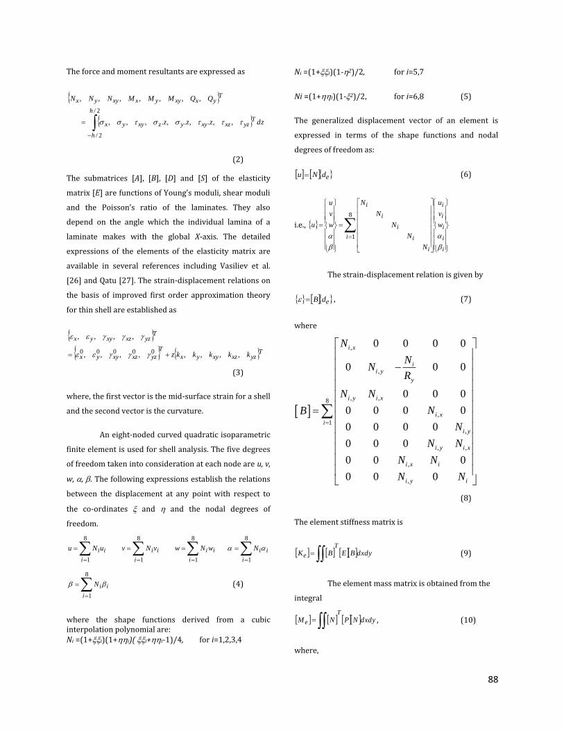
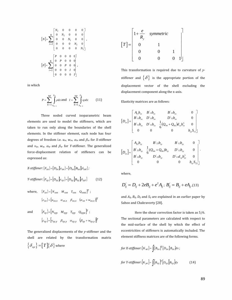
Fig. 3: First mode shapes of laminated composite (+45/-
45/+45/-45) stiffened elliptic paraboloidal shell for
different sizes of the central square cutout (a) /a a =0,
(b) /a a =0.1, (c)
/a a =0.2, (d) /a a =0.3, (e)
/a a
=0.4.
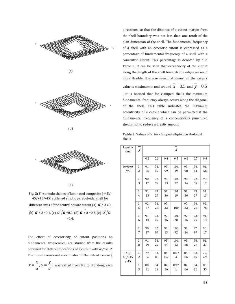
The effect of eccentricity of cutout positions on
fundamental frequencies, are studied from the results
obtained for different locations of a cutout with a//a=0.2.
The non-dimensional coordinates of the cutout centre (
,x y
x ya a
) was varied from 0.2 to 0.8 along each
directions, so that the distance of a cutout margin from
the shell boundary was not less than one tenth of the
plan dimension of the shell. The fundamental frequency
of a shell with an eccentric cutout is expressed as a
percentage of fundamental frequency of a shell with a
concentric cutout. This percentage is denoted by r in
Table 3. It can be seen that eccentricity of the cutout
along the length of the shell towards the edges makes it
more flexible. It is also seen that almost all the cases r
value is maximum in and around 0.5x and 0.5y
. It is noticed that for clamped shells the maximum
fundamental frequency always occurs along the diagonal
of the shell. This table indicates the maximum
eccentricity of a cutout which can be permitted if the
fundamental frequency of a concentrically punctured
shell is not to reduce a drastic amount.
Table 3: Values of ‘r’ for clamped elliptic paraboloidal
shells
Lamina
tion y
x
0.2 0.3 0.4 0.5 0.6 0.7 0.8
0/90/0
/90
0.
2
91.
56
94.
52
99.
99
106.
19
99.
98
94.
51
91.
56
0.
3
90.
17
92.
97
98.
13
104.
72
98.
14
92.
97
90.
17
0.
4
91.
13
93.
27
97.
36
101.
19
97.
36
93.
27
91.
13
0.
5
92.
77
94.
26
97.
32 100
97.
32
94.
25
92.
76
0.
6
91.
13
93.
27
97.
36
101.
20
97.
36
93.
27
91.
13
0.
7
90.
17
92.
97
98.
13
103.
92
98.
14
92.
97
90.
17
0.
8
91.
29
94.
22
99.
64
106.
12
99.
86
94.
28
91.
37
+45/-
45/+45
/-45
0.
2
79.
66
82.
85
84.
84
85.7
4
84.
86
82.
87
79.
69
0.
3
80.
31
84.
19
87.
56
89.7
1
87.
66
84.
28
80.
35
x
y
x
y
x
y

94
0.
4
80.
05
84.
59
90.
03
95.2
9
90.
17
84.
67
80.
08
0.
5
79.
67
84.
63
91.
24 100
91.
22
84.
61
79.
67
0.
6
80.
09
84.
67
90.
19
94.9
5
90.
06
84.
59
80.
08
0.
7
80.
36
84.
28
87.
66
89.5
4
87.
56
84.
20
80.
32
0.
8
79.
57
82.
84
84.
84
85.6
6
84.
87
82.
81
79.
57
CONCLUSIONS
Present results are in close agreement with those of the
benchmark problems. Thus the finite element code used
here is suitable for analyzing free vibration problems of
stiffened elliptic paraboloidal panels with cutouts. The
relative free vibration performances of shells are
expected to be very useful in decision-making for
practicing engineers. The information regarding the
behavior of clamped stiffened elliptic paraboloidal shell
with eccentric cutouts for a wide spectrum of eccentricity
for cross ply and angle ply shells may also be used as
design aids for structural engineers.
REFERENCES
[1] Ghosh B., Bandyopadhyay J.N., Analysis of
paraboloidal of revolution type shell structures using
isoparametric doubly curved shell elements, Computers
& Structures, 1990, 36(5), 791-800.
[2] Dey A., Bandyopadhyay J.N., Sinha P.K., Finite element
analysis of laminated composite paraboloidal of
revolution shells, Computers & Structures, 1992, 44(3),
675-682.
[3] Dey A., Bandyopadhyay J.N., Sinha P.K., Behaviour of
paraboloidal of revolution shell using cross-ply and anti-
symmetric angle-ply laminates, Computers & Structures,
1994, 52(6), 1301-1308.
[4] Chakravorty D., Sinha P.K., Bandyopadhyay J.N., Free
vibration analysis of point supported laminated
composite doubly curved shells- a finite element
approach, Computers & Structures, 1995, 54(2), 191-207.
[5] Chakravorty D., Sinha P.K., Bandyopadhyay J.N., Finite
element free vibration analysis of doubly curved
laminated composite shells, J. Sound and Vibration, 1996,
191(4), 491-504.
[6] Nayak A.N., Bandyopadhyay J.N., Free vibration
analysis and design aids of stiffened conoidal shells.
Journal of Engineering Mechanics, 2002, 128, 419-427.
[7] Nayak A.N., Bandyopadhyay J.N., Free vibration
analysis of laminated stiffened shells, Journal of
Engineering Mechanics, 2005, 131, 100-105.
[8] Nayak A.N., Bandyopadhyay J.N., Dynamic response
analysis of stiffened conoidal shells, Journal of Sound and
Vibration, 2006, 291, 1288-1297.
[9] Das H.S., Chakravorty D., Design aids and selection
guidelines for composite conoidal shell roofs-a finite
element application, Journal of Reinforced Plastic and
Composites, 2007, 26, 1793-1819.
[10] Das H.S., Chakravorty D., Natural frequencies and
mode shapes of composite conoids with complicated
boundary conditions, Journal of Reinforced Plastic and
Composites, 2008, 27, 1397-1415.
[11] Das H.S., Chakravorty D., Finite element application
in analysis and design of point supported composite
conoidal shell roofs suggesting selection guidelines,
Journal of Strain Analysis in Engineering Design., 2010,
45(3), 165-177.
[12] Das H.S., Chakravorty D., Bending analysis of
stiffened composite conoidal shell roofs through finite

95
element application, Journal of Composite Materials,
2011, 45, 525-542.
[13] Pradyumna S., Bandyopadhyay J.N., Static and free
vibration analyses of laminated shells using a higher
order theory. Journal of Reinforced Plastics and
Composites, 2008, 27, 167-186.
[14] Pradyumna S., Bandyopadhyay J.N., Dynamic
instability behaviour of laminated hypar and conoid
shells using a higher-order shear deformation theory,
Thin Walled Structures, 2011, 49, 77-84.
[15] Reddy J.N., Large amplitude flexural vibration of
layered composite plates with cutouts, Journal of Sound
and Vibration, 1982, 83(1), 1-10.
[16] Malhotra S.K., Ganesan N., Veluswami M.A., Vibration
of composite plate with cutouts, Journal of Aeronautical
Society of India, 1989, 41, 61-64.
[17] Sivasubramanian B., Kulkarni A.M., Rao G.V.,
Krishnan A., Free vibration of curved panels with cutouts,
Journal of Sound and Vibration, 1997, 200(2), 227-234.
[18] Sivakumar K., Iyengar N.G.R., Deb K., Free vibration
of laminated composite plates with cutout, Journal of
sound and Vibration, 1999, 221(3), 443-465.
[19] Rossi R.E., Transverse vibrations of thin, orthotropic
rectangular plates with rectangular cutouts with fixed
boundaries, Journal of Sound and Vibration, 1999,
221(4), 733-736.
[20] Huang M., Sakiyama T., Free vibration analysis of
rectangular plates with variously-shaped holes, Journal
of Sound and Vibration, 1999, 226(4), 769-786.
[21] Hota S.S., Padhi P., Vibration of plates with arbitrary
shapes of cutouts, Journal of Sound and Vibration, 2007,
302(4-5), 1030-1036.
[22] Chakravorty D., Sinha P.K., Bandyopadhyay J.N.,
Applications of FEM on free and forced vibration of
laminated shells, Journal of Engineering Mechanics;
1998, 124(1), 1-8.
[23] Sivasubramonian B., Rao G.V., Krishnan A., Free
vibration of longitudinally stiffened curved panels with
cutout, Journal of Sound and Vibration, 1999, 226(1), 41-
55.
[24] Hota S.S., Chakravorty D., Free vibration of stiffened
conoidal shell roofs with cutouts, Journal of Vibration and
Control, 2007, 13(3), 221-240.
[25]Nanda N., Bandyopadhyay J.N., Nonlinear free
vibration analysis of laminated composite cylindrical
shells with cutouts, Journal of Reinforced Plastic and
Composites, 2007, 26(14), 143-1427.
[26] Vasiliev V.V., Jones R.M., Man L.L., Mechanics of
Composite Structures, Taylor and Francis, USA, 1993.
[27] Qatu M.S. , Vibration of Laminated Shells and Plates,
Elsevier, UK, 2004.
[28] Sahoo S., Chakravorty D., Stiffened composite hypar
shell roofs under free vibration: Behaviour and
optimization aids, Journal of Sound and Vibration, 2006,
295, 362-377.