advanced methods for use of numerical …incdmtm.ro/editura/documente/pag. 11-16_advanced … ·...
TRANSCRIPT
Advanced Methods for use of Numerical Control Computer Aided for Optimization of Bearing
Rings Surface Processing
The Romanian Review Precision Mechanics, Optics & Mechatronics, 2015, Issue 47 11
ADVANCED METHODS FOR USE OF NUMERICAL CONTROL
COMPUTER AIDED FOR OPTIMIZATION OF BEARING RINGS
SURFACE PROCESSING
Besnea Daniel1, Donţu Octavian1, Doina Cioboata2, Ciobanu Robert1 , Soare Anamaria Catalina3
1Politehnica University of Bucharest, Splaiul Independenţei, nr. 313, Bucharest, Romania 2The National Institute of Research and Development in Mechatronics and Measurement Technique, Bucharest,
Romania, Sos. Pantelimon, Nr. 6-8 Sector 2, Bucuresti 3SC COMIS Ltd, Romania, Nicolae Iorga Road, No. 83, Valenii de Munte, Prahova, [email protected]
Abstract - In the bearing industry precision of bearings ring manufacturing is a determining factor in the
quality of the finished product. From this point of view, integration of processing machines with CNC
numerical command was a necessity and brought important contributions in optimizing the manufacturing
of the bearing rings.
This paper describes in detail the stages of design and manufacturing of bearing rings on a CNC machine
tool. In the stages of design CAD and production CAM on numerical controlled lathes are presented and
analyzed the process parameters that may influence product quality. Manufacturing of the bearing rings
on CNC machine tools is justified by the performance and flexibility criteria, that lead to increasing of
productivity in the conditions of assurance high level standards of accuracy.
Keywords: CAD/CAM, CNC Lathe Machining, bearing rings.
1. Introduction
Because bearings are used in a wide range of
applications, they must have a number of specific
properties for each area of use, such as: to provide good
sealing, to operate properly at high temperatures, to
provide a accurate rotation movement, to be silent, to
have increased durability in condition of lowest
dimensions, to operate at high and very high speeds etc.
Technological evolution and especially
manufacturing technologies evolution is a key factor in
meeting the requirements of quality and precision
rolling surfaces. However, this technological evolution
involves at the same time increasing the demands
related to accuracy and reliability of the bearing
mechanisms, aiming to obtain bearings with reduced
size, having a longer lifetime and which operate at very
high speeds and high temperatures.
In general, small bearings rings are made of pipe
or bar by turning to obtain a product in raw form.
After turning, the bearing rings are heat treated by
oil quenching process at 820o C, followed by cooling
and high reheating, achieving a hardness value in the
range of 58-65HRC.
To obtain the accuracy required to ensure the
operation of the bearings within the parameters, active
surface of the bearing rings finishing is done by
grinding.
For small bearings with inner diameter up to 25
mm, processing through removal of material by turning
is considered the most economical meeting
requirements of all imposed technological standards [1].
Bearings industry is in continuous evolution and
specific particularities of this industry, respectively
manufacturing a variety of products in large series, in
compliance with strict accuracy standards and as low as
possible execution times, has imposed integrating the
computerized numerically controlled machine tools
(CNC) in the production chain.
Now, as for any other technological product,
conditions relating to functional, reliability and costs
imposed standards of bearings have increased, requiring
manufacturing process optimization through the
implementation of new technologies. Continuous
evolution of the CNC machines and related processes,
led in greater flexibility for rapid adaptation to the
specific conditions of production without great effort,
besides increasing productivity in bearing industry with
compliance with quality standards.
2. Manufacturing of Bearing Rings by Turning
Integrated CAD/CAM systems have been
developed and imposed in the past years achieving and
combining the two adjacent and at the same time
complementary components:
- constructive design component (the proper
design) - CAD (Computer Aided Design);
- technological design (manufacturing) - CAM
(Computer Aided Manufacturing).
To realise a virtual prototype, CAD module
generates models (graphical representations of the
Advanced Methods for use of Numerical Control Computer Aided for Optimization of Bearing
Rings Surface Processing
The Romanian Review Precision Mechanics, Optics & Mechatronics, 2015, Issue 47 12
object to be processed) and knowledge (information
relating to the manufacturing process necessary for
CAM module).
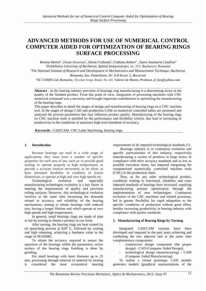
To draw a 2D profile of bearing ring, we use the
Sketcher application of Mechanical Design module,
from the Start menu. This module enables creating,
editing the elements of a sketches and applying
constraints between their components. With the help of
its tools are quick obtained profiles used as supports for
3D bodies, model analysis, highlighting that is one
symmetrically part, represented in Figure 1-a.
Drawing can be done using the options from
Geometry toolbar, using the Sketcher tool, all elements
can be constrained to each other through the
dimensional or geometric constraints. Shaft option
(Figure 1-b) allows to generate solid bodies of
revolution by rotating a 2D profile around an axis
created in the same sketch. [2] [3] [4] [5] [6].
a) b)
Figure 1. 3D module –Bearing ring:
a - Sketch tool.; b –Shaft tool
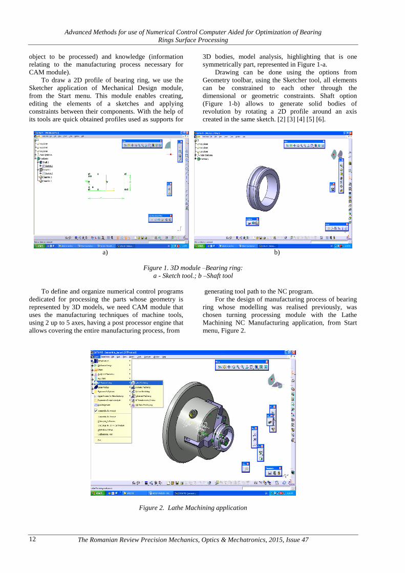
To define and organize numerical control programs
dedicated for processing the parts whose geometry is
represented by 3D models, we need CAM module that
uses the manufacturing techniques of machine tools,
using 2 up to 5 axes, having a post processor engine that
allows covering the entire manufacturing process, from
generating tool path to the NC program.
For the design of manufacturing process of bearing
ring whose modelling was realised previously, was
chosen turning processing module with the Lathe
Machining NC Manufacturing application, from Start
menu, Figure 2.
Figure 2. Lathe Machining application
Advanced Methods for use of Numerical Control Computer Aided for Optimization of Bearing
Rings Surface Processing
The Romanian Review Precision Mechanics, Optics & Mechatronics, 2015, Issue 47 13
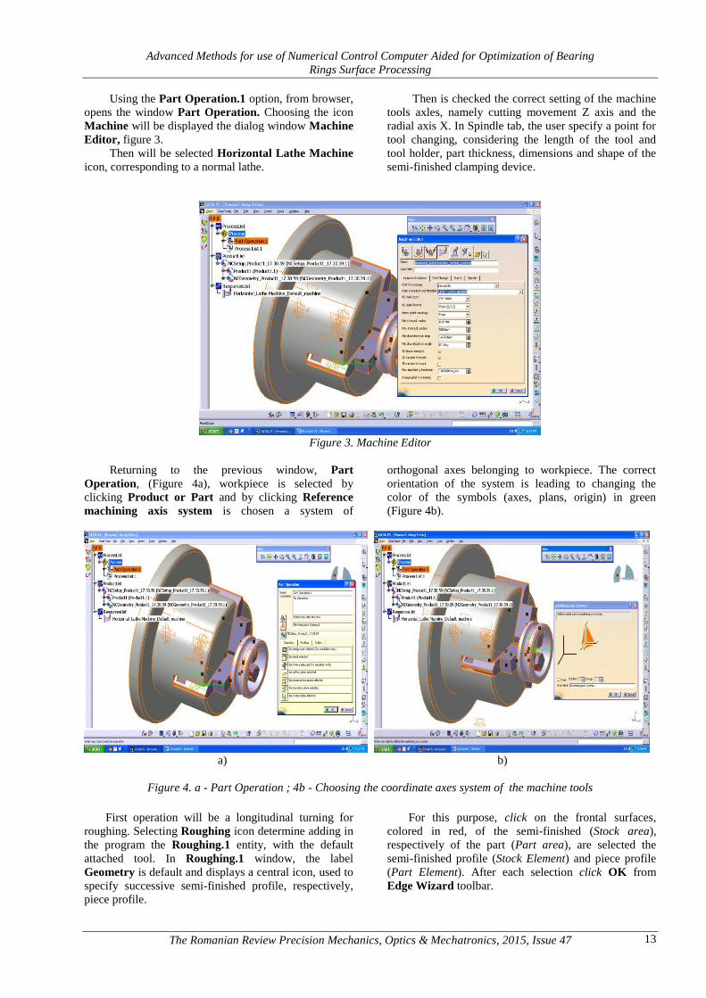
Using the Part Operation.1 option, from browser,
opens the window Part Operation. Choosing the icon
Machine will be displayed the dialog window Machine
Editor, figure 3.
Then will be selected Horizontal Lathe Machine
icon, corresponding to a normal lathe.
Then is checked the correct setting of the machine
tools axles, namely cutting movement Z axis and the
radial axis X. In Spindle tab, the user specify a point for
tool changing, considering the length of the tool and
tool holder, part thickness, dimensions and shape of the
semi-finished clamping device.
Figure 3. Machine Editor
Returning to the previous window, Part
Operation, (Figure 4a), workpiece is selected by
clicking Product or Part and by clicking Reference
machining axis system is chosen a system of
orthogonal axes belonging to workpiece. The correct
orientation of the system is leading to changing the
color of the symbols (axes, plans, origin) in green
(Figure 4b).
a) b)
Figure 4. a - Part Operation ; 4b - Choosing the coordinate axes system of the machine tools
First operation will be a longitudinal turning for
roughing. Selecting Roughing icon determine adding in
the program the Roughing.1 entity, with the default
attached tool. In Roughing.1 window, the label
Geometry is default and displays a central icon, used to
specify successive semi-finished profile, respectively,
piece profile.
For this purpose, click on the frontal surfaces,
colored in red, of the semi-finished (Stock area),
respectively of the part (Part area), are selected the
semi-finished profile (Stock Element) and piece profile
(Part Element). After each selection click OK from
Edge Wizard toolbar.

Advanced Methods for use of Numerical Control Computer Aided for Optimization of Bearing
Rings Surface Processing
The Romanian Review Precision Mechanics, Optics & Mechatronics, 2015, Issue 47 14
Figure 5 Defining the semi-finished and part profiles for longitudinal roughing turning
Then is selected the icon Strategy and are setting
the working parameters. The operation will be done by
clicking the OK button from this window. To simulate
the tool path for this operation, is used the command
Replay Tool Path. In the dialog window associated to
this command is selected the continuous simulation
mode, the tool is positioned in the starting point and
starts the simulation process. The tool will move along
the calculated path. In the same window are displayed
the advance values, basic time and total processing time.
At the end of manufacturing technological process
is providing a finishing turning operation (Figure 6). For
this purpose, is used the Finishing profiles command.
In label Geometry, click the frontal face of the part
icon, colored in red, and on the part model is selected
the final profile Part. After selection click OK.
Figure 6. Defining the part profile for longitudinal finishing turning
To view the path of the cutting tool at finishing
turning operation (Figure 7), is used the command
Replay Tool Path. After enabling Continuous replay
mode icon, the simulation process ca be seen by
successively selecting the appropriate buttons.
Lathe Machining application allows insertion of
other types of operations, using the commands from
menu Insert, Lathe Operations group or the
corresponding icons from the toolbar.
Advanced Methods for use of Numerical Control Computer Aided for Optimization of Bearing
Rings Surface Processing
The Romanian Review Precision Mechanics, Optics & Mechatronics, 2015, Issue 47 15
Figure 7. Longitudinal finishing turning path simulation
The work session ends by generating an APT
source file, to be post-processed for obtaining the
control program of NC lathe.
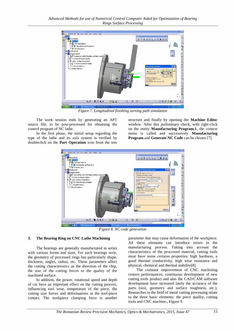
In the first phase, the initial setup regarding the
type of the lathe and its axis system is verified by
doubleclick on the Part Operation icon from the tree
structure and finally by opening the Machine Editor
window. After this preliminary check, with right-click
on the entity Manufacturing Program.1, the context
menu is called and successively Manufacturing
Program and Generate NC Code can be chosen [7].
Figure 8. NC code generation
3. The Bearing Ring on CNC Lathe Machining
The bearings are generally manufactured in series
with various forms and sizes. For each bearings serie,
the geometry of processed rings has particularly shape,
thickness, angles, radius, etc. These parameters affect
the cutting characteristics as the direction of the chip,
the size of the cutting forces or the quality of the
machined surface.
In addition, the power, rotational speed and depth
of cut have an important effect on the cutting process,
influencing tool wear, temperature of the piece, the
cutting size forces and deformations at the tool-piece
contact. The workpiece clamping force is another
parameter that may cause deformation of the workpiece.
All these elements can introduce errors in the
manufacturing process. Taking into account the
characteristics of the processed material, cutting tools
must have some certains properties: high hardness, a
good thermal conductivity, high wear resistance and
physical, chemical and thermal stability[8].
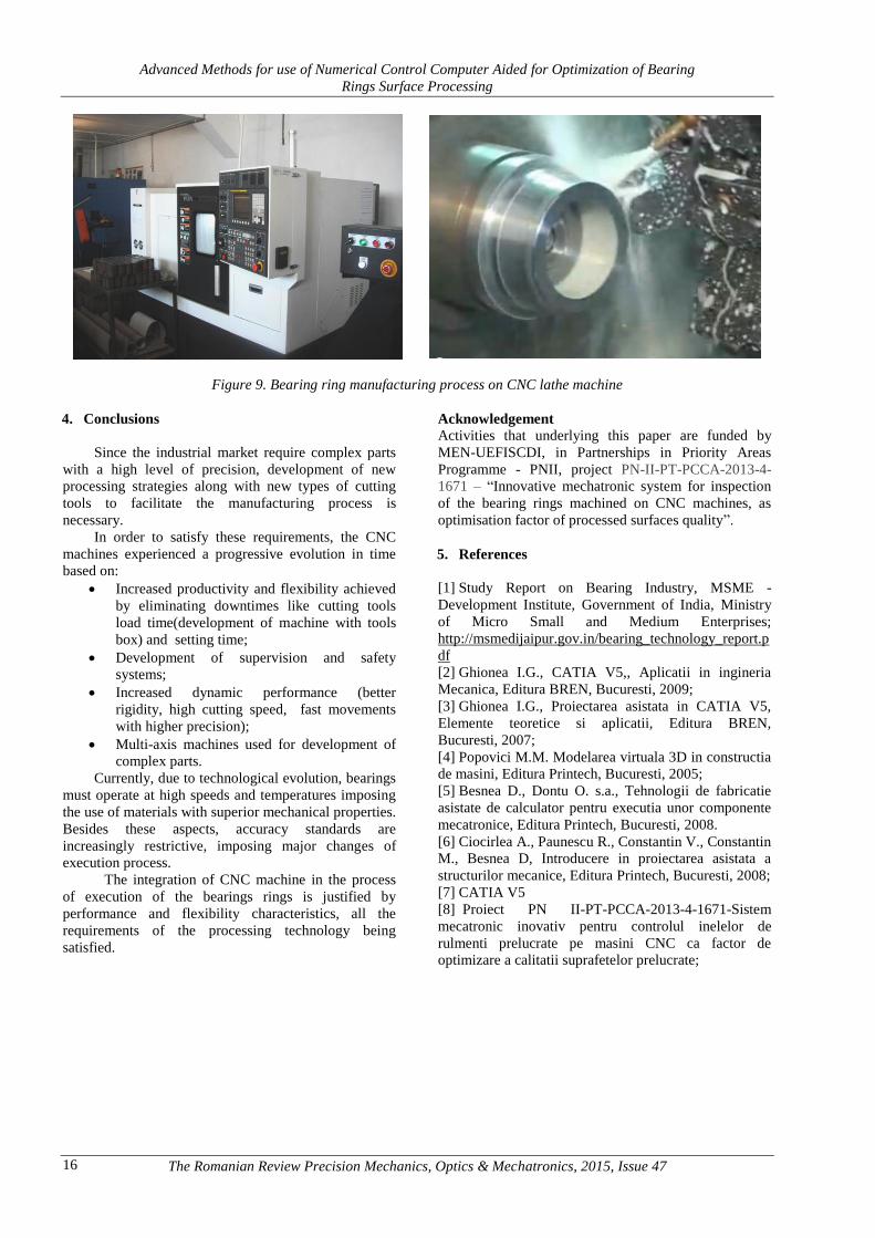
The constant improvement of CNC machining
centers performances, continuous development of new
cutting tools product and also the CAD/CAM software
development have increased lately the accuracy of the
parts (size, geometry and surface roughness, etc.).
Researches in the field of metal cutting processing relate
to the three basic elements: the piece quality, cutting
tools and CNC machine., Figure 9.
Advanced Methods for use of Numerical Control Computer Aided for Optimization of Bearing
Rings Surface Processing
The Romanian Review Precision Mechanics, Optics & Mechatronics, 2015, Issue 47 16
Figure 9. Bearing ring manufacturing process on CNC lathe machine
4. Conclusions
Since the industrial market require complex parts
with a high level of precision, development of new
processing strategies along with new types of cutting
tools to facilitate the manufacturing process is
necessary.
In order to satisfy these requirements, the CNC
machines experienced a progressive evolution in time
based on:
Increased productivity and flexibility achieved
by eliminating downtimes like cutting tools
load time(development of machine with tools
box) and setting time;
Development of supervision and safety
systems;
Increased dynamic performance (better
rigidity, high cutting speed, fast movements
with higher precision);
Multi-axis machines used for development of
complex parts.
Currently, due to technological evolution, bearings
must operate at high speeds and temperatures imposing
the use of materials with superior mechanical properties.
Besides these aspects, accuracy standards are
increasingly restrictive, imposing major changes of
execution process.
The integration of CNC machine in the process
of execution of the bearings rings is justified by
performance and flexibility characteristics, all the
requirements of the processing technology being
satisfied.
Acknowledgement
Activities that underlying this paper are funded by
MEN-UEFISCDI, in Partnerships in Priority Areas
Programme - PNII, project PN-II-PT-PCCA-2013-4-
1671 – “Innovative mechatronic system for inspection
of the bearing rings machined on CNC machines, as
optimisation factor of processed surfaces quality”.
5. References
[1] Study Report on Bearing Industry, MSME -
Development Institute, Government of India, Ministry
of Micro Small and Medium Enterprises;
http://msmedijaipur.gov.in/bearing_technology_report.p
df
[2] Ghionea I.G., CATIA V5,, Aplicatii in ingineria
Mecanica, Editura BREN, Bucuresti, 2009;
[3] Ghionea I.G., Proiectarea asistata in CATIA V5,
Elemente teoretice si aplicatii, Editura BREN,
Bucuresti, 2007;
[4] Popovici M.M. Modelarea virtuala 3D in constructia
de masini, Editura Printech, Bucuresti, 2005;
[5] Besnea D., Dontu O. s.a., Tehnologii de fabricatie
asistate de calculator pentru executia unor componente
mecatronice, Editura Printech, Bucuresti, 2008.
[6] Ciocirlea A., Paunescu R., Constantin V., Constantin
M., Besnea D, Introducere in proiectarea asistata a
structurilor mecanice, Editura Printech, Bucuresti, 2008;
[7] CATIA V5
[8] Proiect PN II-PT-PCCA-2013-4-1671-Sistem
mecatronic inovativ pentru controlul inelelor de
rulmenti prelucrate pe masini CNC ca factor de
optimizare a calitatii suprafetelor prelucrate;