advanced technology and application of large-scale cdq
TRANSCRIPT

ADVANCED TECHNOLOGY AND APPLICATION OF LARGE-SCALE CDQ
Masayuki Watanabe1, Naruo Hamasaki1
1JP Steel Plantech Co., 3-1-11F, Kinko-cho, Kanagawa-ku, Yokohama 221-0056, Japan
Abstract
JP Steel Plantech Co. has the record of having constructed 200 t/h and 185t/h large-scale CDQ. Those CDQs are keeping up the operating ratio of 95% on a calendar base still now, although after-operation 22 years, and 15 years have passed. Moreover, although the steam which these CDQs are generating by the steam boiler is changed into the electric power, It is keeping up 95% also with the utilization rate which divided the actual electric-power-generation output by the electric-power-generation output of rating. In order to achieve these high operating ratios and capacity factors, I introduce the facilities technology which makes realizable the factor and them which are being taken into consideration. 1. Heat exchange in the CDQ furnace and factors to be considered 1) Cooling gas volume The CDQ chamber is a shaft-type heat exchanger as shown in Figure 1. Figure 2 shows the principle of CDQ about heat exchange. To improve its performance, the cooling gas volume needs to be increased. As the cooling gas volume is increased to exceed a certain flow rate (flow velocity), coke particles start to be fluidized in the flues formed in the sidewall. If the gas volume is further increased, the coke particles are carried over through the flues to cause pipe abrasion in the boiler, and therefore, the cooling gas cannot be blown into the furnace over the fluidization limit.
Figure-2 Principle of heat exchanging Figure-1 General flow of CDQ

Figure3 shows the gas temperature variation at the cooling chamber outlet in the case that the retention time in the cooling chamber was 1.5 hours and the cooling gas flow rates were changed from 1100 to 1400m3N/ton-coke. The calculation was made under the condition that the inlet coke temperature was 1000°C and the blowing gas temperature was 160°C. 2) Retention time of coke in the cooling chamber Figure 4 shows the relation between the retention time of coke in the cooling chamber and the cooling gas volume. The inlet coke temperature and the blowing gas temperature were kept constant at 1000°C and 160°C, respectively. The figure shows the effect of the retention time on the coke discharge temperature, when the gas flow rates were changed from 1100 to 1400m3N/ton-coke. It shows that the increase in the cooling gas volume greatly changes the cooling chamber volume needed to secure the coke outlet temperature. 3) Control of gas permeability Coke particle diameters range from those of fine dust to about 150 mm of maximum lumps. To cool coke particles as uniformly as possible in the shaft furnace, they should be charged into the furnace with a proper particle size distribution in both circumferential and radial directions. The method employed to uniform the particle size distribution in the circumferential direction is to use a rotating coke bucket that rotates and collects the coke particles discharged from the coke oven (Figure 5).
Figure-5 Effect of rotating coke bucket
Figure-3 Effect of cooling gas volume Figure-4 Effect of retention time

The method employed to obtain an appropriate particle size distribution in the radial direction is to use an apparatus such as BELL, which was used as the charging apparatus of blast furnaces. This apparatus distributes large lumps in the circumferential part and the central part of the furnace, and uniform the gas velocity in the radial direction to some extent (Figure 6). 4) Descending velocity control of coke The apparatus for blowing the cooling gas from underneath is supported by a single directional beam. This support beam obstructs the descent of the coke particles. The shape of the gas distributor is experimentally determined to be able to uniform the descending velocities of coke particles in the circumferential direction (Figure 7). 5) Application of CDQ Furnace Control Technology In the above Items 1) - 4), the factors to be considered for the heat exchange in the CDQ furnace (cooling gas volume, particle size distribution control, etc.) are described. Figure 8 shows the heat exchange volume between red-hot coke and cooling gas in the efficiency-improved CDQ furnace mentioned above versus the heat volume generated by burning the blowing air in the dust catcher. The power generation volume is also shown in the figure.
Figure-6 Effect of special charging bell
Figure-7 Outline drawing of funnel & distributor
Figure-8 Heat exchange volume & power generation

2. System factors needed to maintain high operation rate In the CDQ process, the parts that need maintenance and replacement are the lined refractories in the furnace and the boiler’s abrasion proof protectors. A CDQ system manufactured by another company and installed in China, for example, needs about 45-day maintenance work after 2 years of operation. 1) Durability of refractories The cooling gas passes through the coke layer in the cooling chamber. The cooling gas superficial velocity is about 2m/s. The actual gas velocity passing through the furnace wall surfaces is therefore estimated to be about 10m/s. The gas naturally accompanies coke dust, causing serious abrasion damage to the furnace wall surfaces. Our recommended cooling zone refractories have the life duration of longer than 10 years, and hence they have excellent abrasion resistance. The joints between the refractories should also be taken into account (Figure 9). 2) Measures to prevent coke particles from scattering from flues It is also important to reduce the abrasion by coke particles in the boiler, the multi-cyclone as the secondary dust collector, and the circulation blower. The normal single flue structure has several tens of large openings on the side, collects the cooling gas to the circular flow passages in the upper part of the CDQ furnace body, and leads the gas to the dust catcher. The areas of the openings are designed to be as large as possible to reduce the gas flow velocity.
Figure-9.1 Photograph of cooling chamber refractory after 1 year operation (Before change of the refractory quality)
Figure-9.2 Photograph of cooling chamber refractory after 8 years operation (After change of the refractory quality)

The increase in height, however, significantly increases the carried-over quantity of coke particles, and hence the width is increased to a maximum extent. The partition wall thickness between the flues is therefore as thin as about 150mm, causing concern about the decrease in the strength of the brick structure (Figure 10). Figure 11 shows the form of accumulated coke particles in the flues. Since the gas flow resistance in the upper parts of the flues differs greatly from that in the lower parts, the gas flow velocity passing through the upper parts is much larger than that passing through the lower parts. As a result, when the cooling gas volume is increased to 1200m3N/ton-coke or more, coke lumps start to be fluidized in the flues, and a large amount of coke particles is carried over to the dust catcher or downstream (Figure 12).
Figure-11 Coke Condition in Flue of CDQ-chamber
Figure-10 Structure of single flue brick
Partition wall
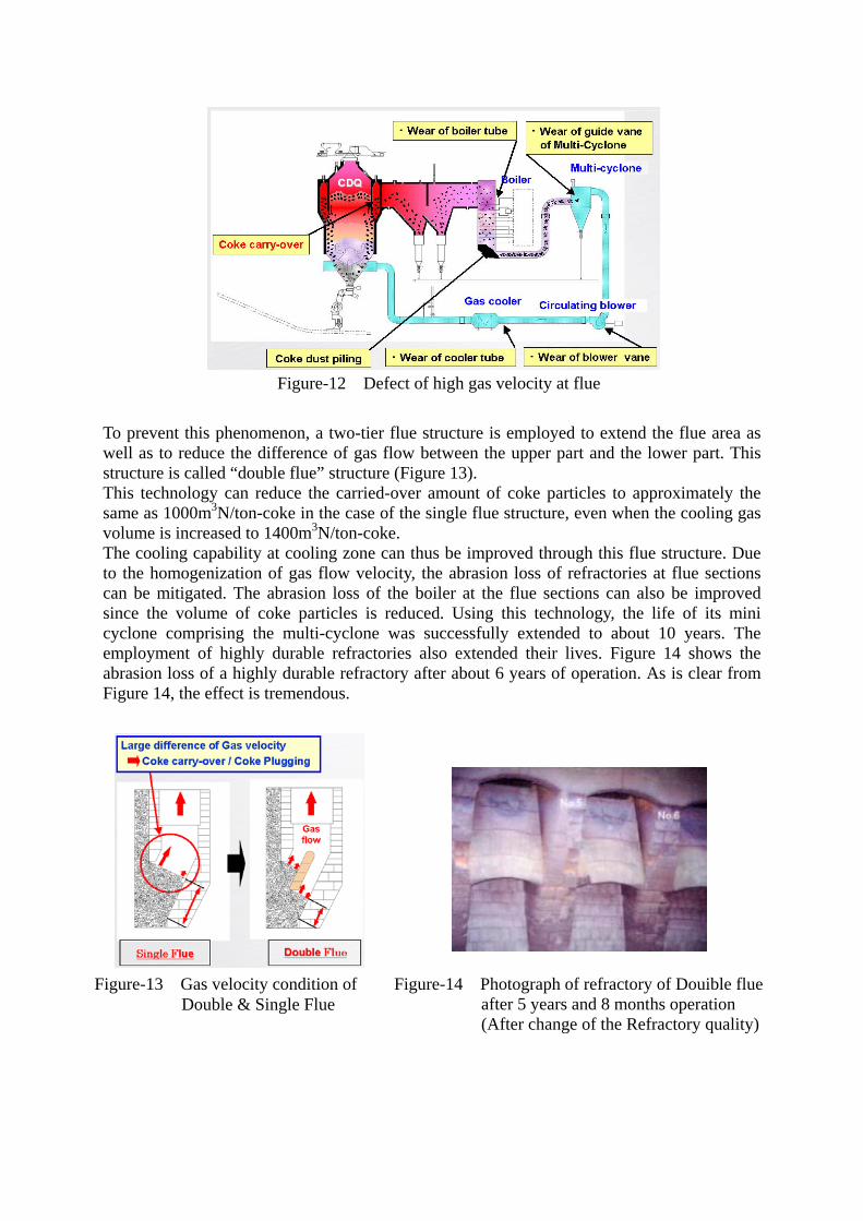
To prevent this phenomenon, a two-tier flue structure is employed to extend the flue area as well as to reduce the difference of gas flow between the upper part and the lower part. This structure is called “double flue” structure (Figure 13). This technology can reduce the carried-over amount of coke particles to approximately the same as 1000m3N/ton-coke in the case of the single flue structure, even when the cooling gas volume is increased to 1400m3N/ton-coke. The cooling capability at cooling zone can thus be improved through this flue structure. Due to the homogenization of gas flow velocity, the abrasion loss of refractories at flue sections can be mitigated. The abrasion loss of the boiler at the flue sections can also be improved since the volume of coke particles is reduced. Using this technology, the life of its mini cyclone comprising the multi-cyclone was successfully extended to about 10 years. The employment of highly durable refractories also extended their lives. Figure 14 shows the abrasion loss of a highly durable refractory after about 6 years of operation. As is clear from Figure 14, the effect is tremendous.
Figure-13 Gas velocity condition of Double & Single Flue
Figure-14 Photograph of refractory of Douible flue after 5 years and 8 months operation (After change of the Refractory quality)
Figure-12 Defect of high gas velocity at flue

3) Structure of dust catcher Figures 15 and 16 show the flow line charts comparing the cases with and without the collision wall in the dust catcher. Although the dust collection efficiency of the dust catcher is about 25% and not very high, the addition of a collision wall enables the catching of coke particles, in particular, with a large diameter (Figure 17). Large size coke particles contained in the circulating gas obviously increase the degree of abrasion of the boiler and the multi-cyclone.
0
10
20
30
40
50
60
70
80
90
100
0.E+00 2.E- 03 4.E- 03 6.E- 03 8.E- 03
Particles diameter Dp(m)
Collection efficiency(wt%
With collision wall
Without collision wall
Figure-17 The dust collection efficiency
Figure-15 The flow line charts comparing the cases with collision wall
Figure-16 The flow line charts comparing the cases without collision wall
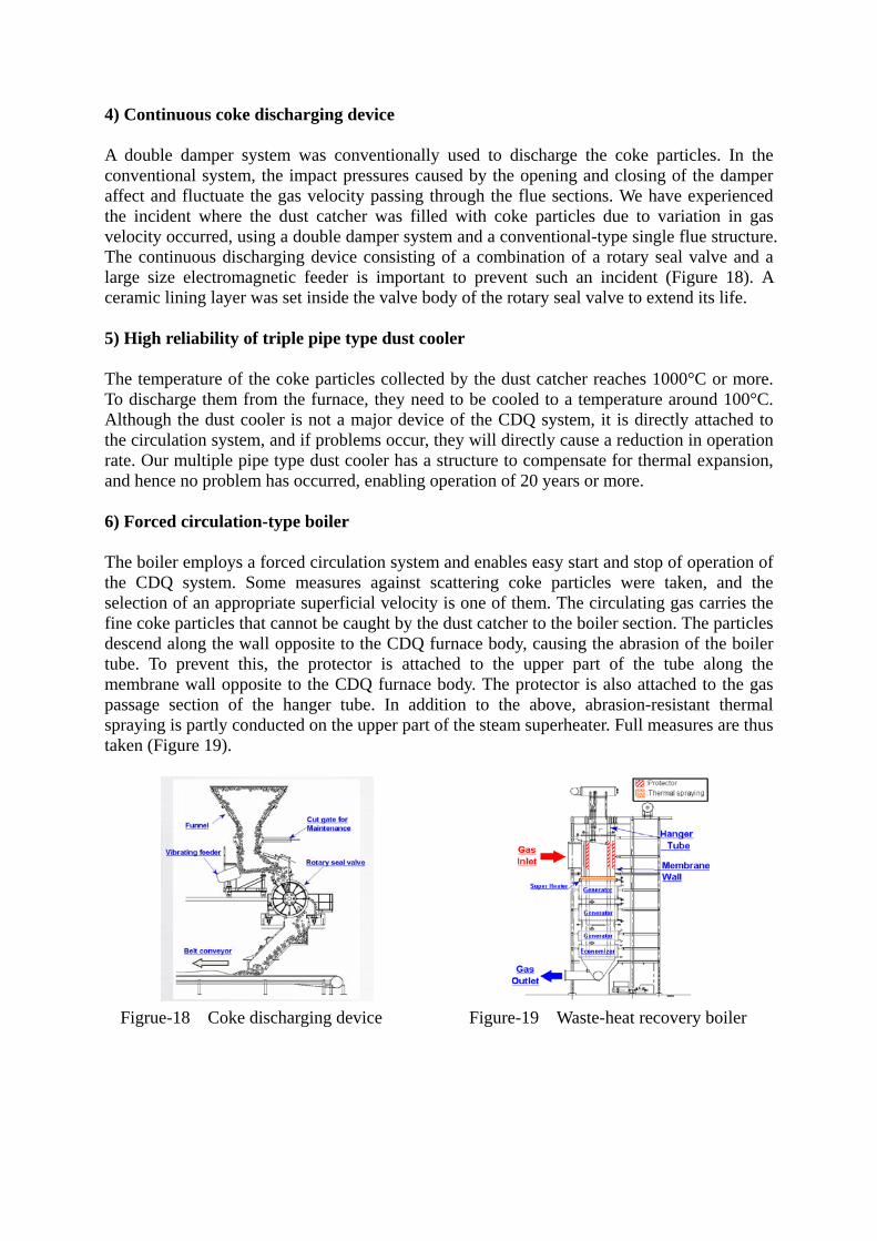
4) Continuous coke discharging device A double damper system was conventionally used to discharge the coke particles. In the conventional system, the impact pressures caused by the opening and closing of the damper affect and fluctuate the gas velocity passing through the flue sections. We have experienced the incident where the dust catcher was filled with coke particles due to variation in gas velocity occurred, using a double damper system and a conventional-type single flue structure. The continuous discharging device consisting of a combination of a rotary seal valve and a large size electromagnetic feeder is important to prevent such an incident (Figure 18). A ceramic lining layer was set inside the valve body of the rotary seal valve to extend its life. 5) High reliability of triple pipe type dust cooler The temperature of the coke particles collected by the dust catcher reaches 1000°C or more. To discharge them from the furnace, they need to be cooled to a temperature around 100°C. Although the dust cooler is not a major device of the CDQ system, it is directly attached to the circulation system, and if problems occur, they will directly cause a reduction in operation rate. Our multiple pipe type dust cooler has a structure to compensate for thermal expansion, and hence no problem has occurred, enabling operation of 20 years or more. 6) Forced circulation-type boiler The boiler employs a forced circulation system and enables easy start and stop of operation of the CDQ system. Some measures against scattering coke particles were taken, and the selection of an appropriate superficial velocity is one of them. The circulating gas carries the fine coke particles that cannot be caught by the dust catcher to the boiler section. The particles descend along the wall opposite to the CDQ furnace body, causing the abrasion of the boiler tube. To prevent this, the protector is attached to the upper part of the tube along the membrane wall opposite to the CDQ furnace body. The protector is also attached to the gas passage section of the hanger tube. In addition to the above, abrasion-resistant thermal spraying is partly conducted on the upper part of the steam superheater. Full measures are thus taken (Figure 19).
Figrue-18 Coke discharging device Figure-19 Waste-heat recovery boiler

7) Maintainability improvement using a rope trolley type hoisting crane Overhead traveling cranes are employed in conventional bucket hoisting devices. The conventional systems, however, need winch maintenance work at a high place and a high maintenance space on the furnace top. So, a rope trolley type hoisting crane was developed to solve these problems (Figure 20). This system places the winch on the ground to facilitate maintenance work, eliminates the maintenance space on the furnace top, and reduces the weight moving over the furnace top by about 100 tons, resulting in a reduction in frame weight. 3. Conclusion The above summarizes the process evolution and plant technology that have been studied to realize a high-performance, high operation rate large size CDQ system. Lacking any factor or device leads to difficulty in maintaining the high operation rate and the high utilization rate of the CDQ system. The factors leading to the realization of such a CDQ system have been developed in Japanese steel companies together with their customers. We would like to make effort to spread these technologies to maximize energy saving and minimize CO2 emissions, contributing to the global environmental preservation.
Figure-20 Coke bucket hoisting crane - rope trolley type