advanced technology solar telescope...
TRANSCRIPT
Conservation District Use Application (CDUA)
for the
Advanced Technology Solar Telescope (ATST)
Haleakalā High Altitude Observatory Site
Haleakalā, Maui, HI
March 10, 2010
Prepared for:
University of Hawai‗i, Institute for Astronomy
2680 Woodlawn Drive
Honolulu, HI 96822
www.ifa.hawaii.edu
Prepared by:
KC Environmental, Inc.
P.O. Box 1208
Makawao, HI 96768
www.kcenv.com

THIS PAGE INTENTIONALLY LEFT BLANK
EXECUTIVE SUMMARY
This Conservation District Use Application (CDUA) is being submitted by the University of Hawai‗i
Institute for Astronomy (IfA) for the development of the Advanced Technology Solar Telescope (ATST)
within the 18.166-acre Haleakalā High Altitude Observatory Site (HO) at the summit of Haleakalā, County
of Maui, Hawai‗i. The HO site is located in a General Subzone of the Conservation District, in Tax Map
Key (TMK) (2) 2-2-07-008. Maui County Code 16.26.101.3 exempts HO from County regulation.
In 1961, Executive Order (EO) 1987 established HO and placed it under the control and management of
the Board of Regents of the University of Hawai‗i. EO 1987 has no expiration date and stipulates: ―That
the lands… set aside shall be used for Haleakalā High Altitude Observatory Site purposes only.‖
Public Access
As stipulated in EO 1987, the HO is not open to the general public. Most observatory personnel working
at HO during daylight hours are involved in maintenance and engineering activities that do not facilitate
tours. However, by special arrangement, the University of Hawai‗i does provide educational tours of its
facilities. During nighttime hours, observatories at HO are conducting research employing the most
advanced astronomical and space surveillance instruments in the world. HO‘s instrumentation is
extremely sensitive to light and therefore, vehicle traffic restrictions through HO are rigorously enforced.
Cultural Resources
Those who are descendants of Native Hawaiians who inhabited the Hawaiian Islands prior to 1778
possess Native Hawaiian traditional and customary rights. These rights are uniquely held by this group of
people and not shared by the general public. What those rights are and how they are exercised is
determined on a case-by-case basis, as there are no definitions that apply across all situations or in all
places. Customary practices can also change over time. The IfA has taken steps to help ensure that Native
Hawaiians are welcome to enter HO for cultural practices. A sign has been provided by IfA with
instructions meant only for Native Hawaiians and is posted at the entrance to HO. Additionally, an area
consisting of approximately 24,000 square feet and located on the western side of HO has been set aside
in perpetuity for the sole reverent use of Native Hawaiians for religious and cultural purposes. The area
includes an ahu and other archaeological features.
Natural Resources Management
The objective for management of observatory facilities is to create a structure for sustainable, focused
management of the resources and operations of the observatories at HO, in order to protect
historic/cultural resources: e.g. archaeology sites, traditional cultural practices, to protect natural
resources, protect and enhance education and research, and to provide a base for future expansion of the
scope of activities at HO. Specific methods and techniques are discussed in detail in this CDUA and the
HO Management Plan.
Advanced Technology Solar Telescope The 1998 National Academy of Sciences/National Research Council report entitled ―Ground-Based Solar
Research: An Assessment and Strategy for the Future‖, and the 2000 National Science Foundation (NSF)
and National Aeronautics and Space Administration (NASA) ―Astronomy & Astrophysics Survey
Committee Decadal Survey‖, highly recommended the development of an Advanced Technology Solar
Telescope (ATST). The ATST would be the world's flagship facility for the study of magnetic
phenomena in the solar atmosphere and would be the first large, ground-based, open-access solar
telescope constructed in the United States in more than 40 years. In December 2009, the Record of
Decision (ROD) by NSF on the Final Environmental Impact Statement for this project approved funding
for ATST at HO. Frequently asked questions about this project are summarized below:
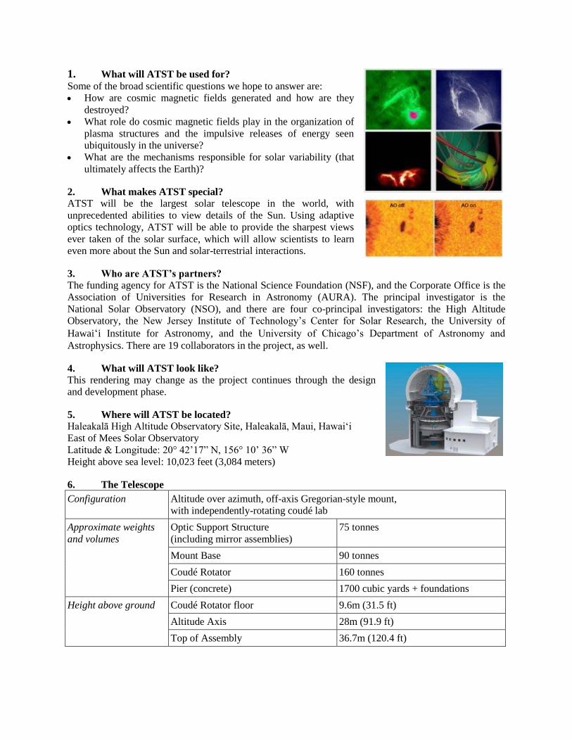
1. What will ATST be used for? Some of the broad scientific questions we hope to answer are:
How are cosmic magnetic fields generated and how are they
destroyed?
What role do cosmic magnetic fields play in the organization of
plasma structures and the impulsive releases of energy seen
ubiquitously in the universe?
What are the mechanisms responsible for solar variability (that
ultimately affects the Earth)?
2. What makes ATST special?
ATST will be the largest solar telescope in the world, with
unprecedented abilities to view details of the Sun. Using adaptive
optics technology, ATST will be able to provide the sharpest views
ever taken of the solar surface, which will allow scientists to learn
even more about the Sun and solar-terrestrial interactions.
3. Who are ATST’s partners?
The funding agency for ATST is the National Science Foundation (NSF), and the Corporate Office is the
Association of Universities for Research in Astronomy (AURA). The principal investigator is the
National Solar Observatory (NSO), and there are four co-principal investigators: the High Altitude
Observatory, the New Jersey Institute of Technology‘s Center for Solar Research, the University of
Hawai‗i Institute for Astronomy, and the University of Chicago‘s Department of Astronomy and
Astrophysics. There are 19 collaborators in the project, as well.
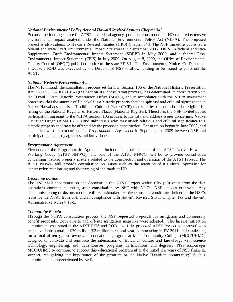
4. What will ATST look like?
This rendering may change as the project continues through the design
and development phase.
5. Where will ATST be located?
Haleakalā High Altitude Observatory Site, Haleakalā, Maui, Hawai‗i
East of Mees Solar Observatory
Latitude & Longitude: 20° 42‘17‖ N, 156° 10‘ 36‖ W
Height above sea level: 10,023 feet (3,084 meters)
6. The Telescope
Configuration Altitude over azimuth, off-axis Gregorian-style mount,
with independently-rotating coudé lab
Approximate weights
and volumes
Optic Support Structure
(including mirror assemblies)
75 tonnes
Mount Base 90 tonnes
Coudé Rotator 160 tonnes
Pier (concrete) 1700 cubic yards + foundations
Height above ground Coudé Rotator floor 9.6m (31.5 ft)
Altitude Axis 28m (91.9 ft)
Top of Assembly 36.7m (120.4 ft)
National Environmental Policy Act and Hawai‘i Revised Statutes Chapter 343
Because the funding source for ATST is a federal agency, potential construction at HO required extensive
environmental impact analysis under the National Environmental Policy Act (NEPA). The proposed
project is also subject to Hawai‗i Revised Statutes (HRS) Chapter 343. The NSF therefore published a
federal and state Draft Environmental Impact Statement in September 2006 (DEIS), a federal and state
Supplemental Draft Environmental Impact Statement (SDEIS) in May 2009, and a federal Final
Environmental Impact Statement (FEIS) in July 2009. On August 8, 2009, the Office of Environmental
Quality Control (OEQC) published notice of the state FEIS in The Environmental Notice. On December
3, 2009, a ROD was executed by the Director of NSF to allow funding to be issued to construct the
ATST.
National Historic Preservation Act
The NSF, through the consultation process set forth in Section 106 of the National Historic Preservation
Act, 16 U.S.C. 470f (NHPA) (the Section 106 consultation process), has determined, in consultation with
the Hawai‗i State Historic Preservation Office (SHPO), and in accordance with the NHPA assessment
processes, that the summit of Haleakalā is a historic property that has spiritual and cultural significance to
Native Hawaiians and is a Traditional Cultural Place (TCP) that satisfies the criteria to be eligible for
listing on the National Register of Historic Places (National Register). Therefore, the NSF invited public
participation pursuant to the NHPA Section 106 process to identify and address issues concerning Native
Hawaiian Organizations (NHO) and individuals who may attach religious and cultural significance to a
historic property that may be affected by the proposed construction. Consultation began in June 2005, and
concluded with the execution of a Programmatic Agreement in September of 2009 between NSF and
participating signatory agencies and individuals.
Programmatic Agreement
Elements of the Programmatic Agreement include the establishment of an ATST Native Hawaiian
Working Group (ATST NHWG). The role of the ATST NHWG will be to provide consultation
concerning historic property matters related to the construction and operation of the ATST Project. The
ATST NHWG will provide consultation on issues such as the retention of a Cultural Specialist for
construction monitoring and the naming of the roads at HO.
Decommissioning
The NSF shall decommission and deconstruct the ATST Project within fifty (50) years from the date
operations commence, unless, after consultation by NSF with NHOs, NSF decides otherwise. Any
decommissioning or deconstruction will be undertaken per the terms and conditions defined in the NSF‘s
lease for the ATST from UH, and in compliance with Hawai‗i Revised Status Chapter 183 and Hawai‗i
Administrative Rules § 13-5.
Community Benefit
Through the NHPA consultation process, the NSF requested proposals for mitigation and community
benefit proposals. Both on-site and off-site mitigation measures were adopted. The largest mitigation
commitment was noted in the ATST FEIS and ROD: ―-- if the proposed ATST Project is approved -- to
make available a total of $20 million ($2 million per fiscal year, commencing in FY 2011, and continuing
for a total of ten years) towards an educational program at Maui Community College (MCC/UHMC)
designed to cultivate and reinforce the intersection of Hawaiian culture and knowledge with science
technology, engineering, and math courses, programs, certifications, and degrees. NSF encourages
MCC/UHMC to continue to support this educational program after the initial ten years of NSF financial
support, recognizing the importance of the program to the Native Hawaiian community;‖ Such a
commitment is unprecedented by NSF.
Federal Endangered Species Act
Through lengthy consultation related to the NSF‘s compliance with the Federal Endangered Species Act
of 1973, as amended (16 USC1531, et seq.), and pursuant to Chapter 195D, Hawai‗i Revised Statutes
(HRS 195D), the NSF agreed to, and is in the process of obtaining approval from the Board of Land and
Natural Resources to voluntarily implement a Habitat Conservation Plan (HCP) to mitigate, minimize,
monitor, and report on any potential negative impact to endangered species related to the construction and
operation of the ATST at HO. The HCP will have multiple-year financial assurance from the ATST
Project to implement the Plan. The HCP will have multiple year financial assurance from NSF, through
the ATST Project, to implement the HCP. The HCP includes full-time staffing at ATST to implement
and carry out the required mitigation, minimization, monitoring, and reporting measures and tasks,
together with any adaptive management measures that may be necessary to adjust the ATST Project‘s
approach, in order to achieve a net recovery benefit during the duration of the HCP.
- 1 – State of Hawaii, Department of Land and Natural Resources, Conservation District Use Application, 11/17/2008 Revised
Conservation District Use Application (CDUA)
For DLNR Use
File # ______________
Reviewed by ______________
Date ______________
Accepted by Date ______________
180-Day Exp. ______________
EA/EIS Required ______________
PH Required ______________
Decision ______________
Date ______________
Project Location/Address: University of Hawai‗i, Institute for Astronomy, Haleakalā High Altitude Observatories (HO) Site
District: Waiakoa, Papaanui, Makawao County: Maui
Island: Maui Tax Map Key(s): 2-2-2-007-008
Total Area of Parcel: 18.166 acres (HO) Area of Proposed Use: 0.86 acres
(proposed ATST Project)
Commencement Date: 180 days from Completion Date: Approximately 7 years
Submission of CDUA from issuance of CDUP
Indicate which of the following approvals are being sought, as specified in the Hawai`i Administrative
Rules (HAR), Chapter 13-5.
X Board Permit
Departmental Permit
___ Emergency Permit
___ Temporary Permit
___ Site Plan Approval

- 2 – State of Hawaii, Department of Land and Natural Resources, Conservation District Use Application, 11/17/2008 Revised
THIS PAGE INTENTIONALLY LEFT BLANK
- 3 – State of Hawaii, Department of Land and Natural Resources, Conservation District Use Application, 11/17/2008 Revised
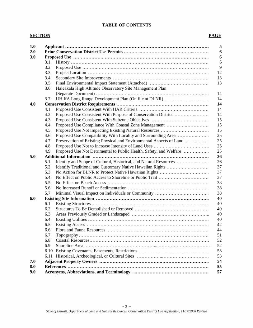
TABLE OF CONTENTS
SECTION PAGE
1.0 Applicant …………….……………………………………………………………………. 5
2.0 Prior Conservation District Use Permits ………...……………………………... ……… 6
3.0 Proposed Use ……………….…………………………………………………………….. 6
3.1 History ………….…………………………………………………………………… 6
3.2 Proposed Use ……….……….………………………………………………………. 9
3.3 Project Location …………………………………………………………………….. 12
3.4 Secondary Site Improvements ……………………………………………………… 13
3.5 Final Environmental Impact Statement (Attached) ………….……………………… 13
3.6 Haleakalā High Altitude Observatory Site Management Plan
(Separate Document) ………………….………………………………………….…. 14
3.7 UH IfA Long Range Development Plan (On file at DLNR) ………….……………. 14
4.0 Conservation District Requirements ……….…………………………………………… 14
4.1 Proposed Use Consistent With HAR Criteria …………….………………………… 14
4.2 Proposed Use Consistent With Purpose of Conservation District …………..……… 14
4.3 Proposed Use Consistent With Subzone Objectives ……………………………….. 15
4.4 Proposed Use Compliance With Coastal Zone Management ………….…………… 15
4.5 Proposed Use Not Impacting Existing Natural Resources ……….…………………. 15
4.6 Proposed Use Compatibility With Locality and Surrounding Area ………….…….. 25
4.7 Preservation of Existing Physical and Environmental Aspects of Land ……..…….. 25
4.8 Proposed Use Not to Increase Intensity of Land Uses ……….……………………… 25
4.9 Proposed Use Not Detrimental to Public Health, Safety, and Welfare …………….. 25 5.0 Additional Information …………….……………………………………………………. 26
5.1 Identity and Scope of Cultural, Historical, and Natural Resources …………..…….. 26
5.2 Identify Traditional and Customary Native Hawaiian Rights …………….………… 37
5.3 No Action for BLNR to Protect Native Hawaiian Rights ……………….………….. 37
5.4 No Effect on Public Access to Shoreline or Public Trail …………………………… 37
5.5 No Effect on Beach Access …………………………………………….…………… 38
5.6 No Increased Runoff or Sedimentation ……………………………….…………….. 38
5.7 Minimal Visual Impact on Individuals or Community ……………….…………….. 38
6.0 Existing Site Information ……………………………………….……………………….. 40
6.1 Existing Structures …………………………………………..………………………. 40
6.2 Structures To Be Demolished or Removed ……………….………………………… 40
6.3 Areas Previously Graded or Landscaped ….…………….………………………….. 40
6.4 Existing Utilities ……………………………………….……………………………. 40
6.5 Existing Access ………….…………………………….……………………………. 42
6.6 Flora and Fauna Resources …………………………..……………………………… 44
6.7 Topography …………………………….………….………………………………… 51
6.8 Coastal Resources……………………………………………………………………. 52
6.9 Shoreline Area ………………………………………....……………………………. 52
6.10 Existing Covenants, Easements, Restrictions …………….………………………… 53
6.11 Historical, Archeological, or Cultural Sites ……………..…………………………. 53
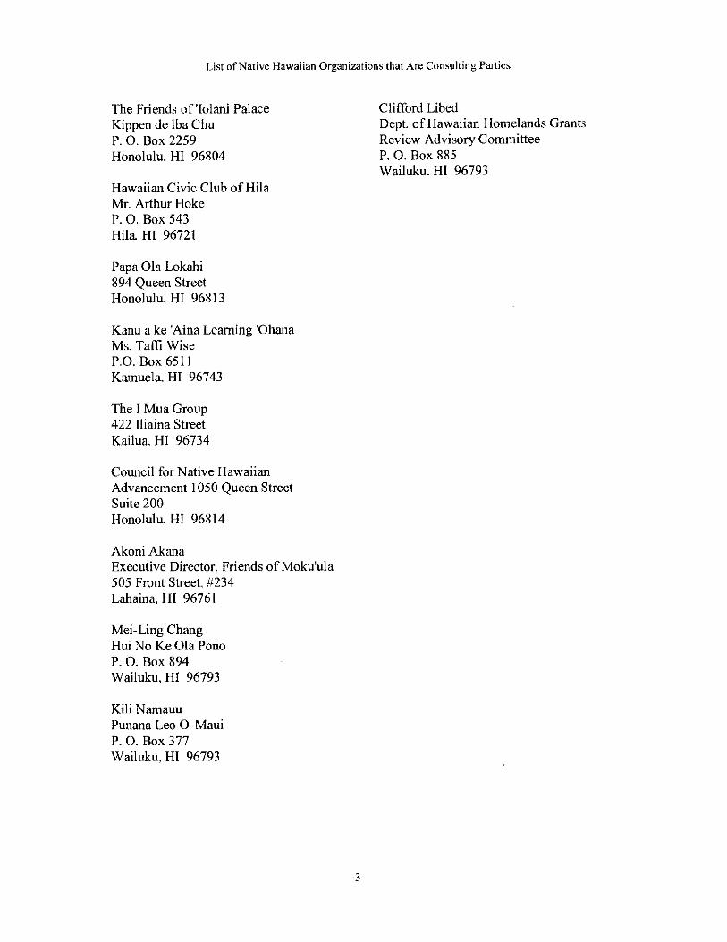
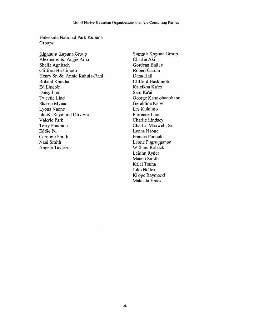
7.0 Adjacent Property Owners ….……………………………….………………………….. 54
8.0 References ………………………………………………………………………………… 55
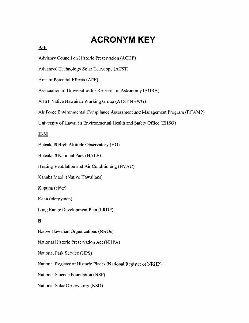
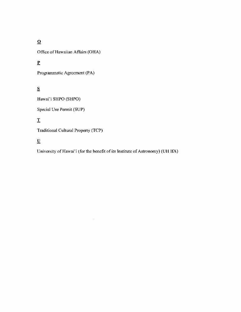
9.0 Acronyms, Abbreviations, and Terminology ...………………………………………… 57
- 4 – State of Hawaii, Department of Land and Natural Resources, Conservation District Use Application, 11/17/2008 Revised
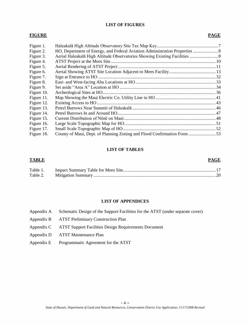
LIST OF FIGURES
FIGURE PAGE
Figure 1. Haleakalā High Altitude Observatory Site Tax Map Key ...................................................... 7 Figure 2. HO, Department of Energy, and Federal Aviation Administration Properties ...................... 8 Figure 3. Aerial Haleakalā High Altitude Observatories Showing Existing Facilities ......................... 8 Figure 4. ATST Project at the Mees Site ............................................................................................. 10 Figure 5. Aerial Rendering of ATST Project ...................................................................................... 11 Figure 6. Aerial Showing ATST Site Location Adjacent to Mees Facility ......................................... 13 Figure 7. Sign at Entrance to HO ........................................................................................................ 32 Figure 8. East- and West-facing Ahu Locations at HO ....................................................................... 33 Figure 9. Set aside ―Area A‖ Location at HO ..................................................................................... 34 Figure 10. Archeological Sites at HO .................................................................................................... 36 Figure 11. Map Showing the Maui Electric Co. Utility Line in HO ..................................................... 41 Figure 12. Existing Access to HO ......................................................................................................... 43 Figure 13. Petrel Burrows Near Summit of Haleakalā .......................................................................... 46 Figure 14. Petrel Burrows In and Around HO ....................................................................................... 47 Figure 15. Current Distribution of Nēnē on Maui ................................................................................. 48 Figure 16. Large Scale Topographic Map for HO ................................................................................. 51 Figure 17. Small Scale Topographic Map of HO .................................................................................. 52 Figure 18. County of Maui, Dept. of Planning Zoning and Flood Confirmation Form ........................ 53
LIST OF TABLES
TABLE PAGE
Table 1. Impact Summary Table for Mees Site.................................................................................. 17 Table 2. Mitigation Summary ............................................................................................................ 20
LIST OF APPENDICES
Appendix A Schematic Design of the Support Facilities for the ATST (under separate cover)
Appendix B ATST Preliminary Construction Plan
Appendix C ATST Support Facilities Design Requirements Document
Appendix D ATST Maintenance Plan
Appendix E Programmatic Agreement for the ATST
- 5 – State of Hawaii, Department of Land and Natural Resources, Conservation District Use Application, 11/17/2008 Revised
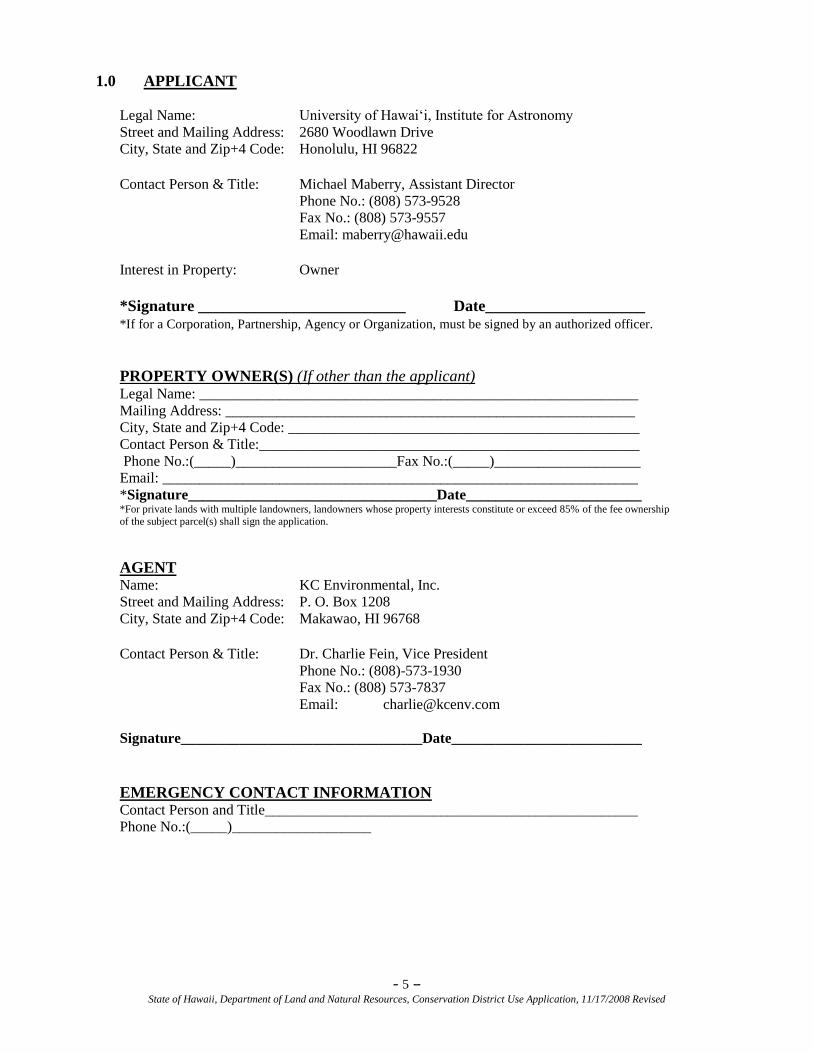
1.0 APPLICANT
Legal Name: University of Hawai‗i, Institute for Astronomy
Street and Mailing Address: 2680 Woodlawn Drive
City, State and Zip+4 Code: Honolulu, HI 96822
Contact Person & Title: Michael Maberry, Assistant Director
Phone No.: (808) 573-9528
Fax No.: (808) 573-9557
Email: [email protected]
Interest in Property: Owner
*Signature __________________________ Date____________________ *If for a Corporation, Partnership, Agency or Organization, must be signed by an authorized officer.
PROPERTY OWNER(S) (If other than the applicant) Legal Name: ____________________________________________________________
Mailing Address: ________________________________________________________
City, State and Zip+4 Code: ________________________________________________
Contact Person & Title:____________________________________________________
Phone No.:(_____)______________________Fax No.:(_____)____________________
Email: _________________________________________________________________
*Signature__________________________________Date________________________ *For private lands with multiple landowners, landowners whose property interests constitute or exceed 85% of the fee ownership
of the subject parcel(s) shall sign the application.
AGENT Name: KC Environmental, Inc.
Street and Mailing Address: P. O. Box 1208
City, State and Zip+4 Code: Makawao, HI 96768
Contact Person & Title: Dr. Charlie Fein, Vice President
Phone No.: (808)-573-1930
Fax No.: (808) 573-7837
Email: [email protected]
Signature_________________________________Date__________________________
EMERGENCY CONTACT INFORMATION Contact Person and Title___________________________________________________
Phone No.:(_____)___________________
- 6 – State of Hawaii, Department of Land and Natural Resources, Conservation District Use Application, 11/17/2008 Revised
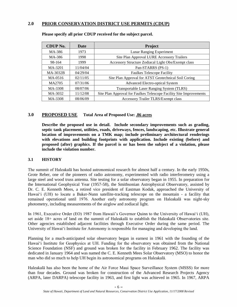
2.0 PRIOR CONSERVATION DISTRICT USE PERMITS (CDUP)
Please specify all prior CDUP received for the subject parcel.
CDUP No. Date Project
MA-386 1973 Lunar Ranging Experiment
MA-386 1998 Site Plan Approval LURE Accessory Trailers
98-164 1999 Accessory Structure Zodiacal Light Obs/Exempt class
MA-3201 11/04/04 Pan-STARRS (PS-1)
MA-3032B 04/29/04 Faulkes Telescope Facility
MA-0516 02/11/05 Site Plan Approval for ATST Geotechnical Soil Coring
MA2705 07/31/06 Advanced Electro-optical System
MA-3308 08/07/06 Transportable Laser Ranging System (TLRS)
MA-3032 11/12/08 Site Plan Approval for Faulkes Telescope Facility Site Improvements
MA-3308 08/06/09 Accessory Trailer TLRS/Exempt class
3.0 PROPOSED USE Total Area of Proposed Use: .86 acres
Describe the proposed use in detail. Include secondary improvements such as grading,
septic tank placement, utilities, roads, driveways, fences, landscaping, etc. Illustrate general
location of improvements on a TMK map; include preliminary architectural renderings
with elevations and building footprints with application. Include existing (before) and
proposed (after) graphics. If the parcel is or has been the subject of a violation, please
include the violation number.
3.1 HISTORY
The summit of Haleakalā has hosted astronomical research for almost half a century. In the early 1950s,
Grote Reber, one of the pioneers of radio astronomy, experimented with radio interferometry using a
large steel and wood truss antenna. Site testing for a solar observatory began in 1955. In preparation for
the International Geophysical Year (1957-58), the Smithsonian Astrophysical Observatory, assisted by
Dr. C. E. Kenneth Mees, a retired vice president of Eastman Kodak, approached the University of
Hawai‗i (UH) to locate a Baker-Nunn satellite-tracking telescope on the mountain - a facility that
remained operational until 1976. Another early astronomy program on Haleakalā was night-sky
photometry, including measurements of the airglow and zodiacal light.
In 1961, Executive Order (EO) 1987 from Hawaii‘s Governor Quinn to the University of Hawai‗i (UH),
set aside 18+ acres of land on the summit of Haleakalā to establish the Haleakalā Observatories site.
Other agencies established adjacent facilities through Executive Order during the same period. The
University of Hawai‗i Institute for Astronomy is responsible for managing and developing the land.
Planning for a much-anticipated solar observatory began in earnest in 1961 with the founding of the
Hawai‗i Institute for Geophysics at UH. Funding for the observatory was obtained from the National
Science Foundation (NSF) and ground was broken for the facility in February 1962. The facility was
dedicated in January 1964 and was named the C. E. Kenneth Mees Solar Observatory (MSO) to honor the
man who did so much to help UH begin its astronomical programs on Haleakalā.
Haleakalā has also been the home of the Air Force Maui Space Surveillance System (MSSS) for more
than four decades. Ground was broken for construction of the Advanced Research Projects Agency
(ARPA, later DARPA) telescope facility in 1963, and first light was achieved in 1965. In 1967, ARPA
- 7 – State of Hawaii, Department of Land and Natural Resources, Conservation District Use Application, 11/17/2008 Revised
designated the site for Western Test Range midcourse observations under the auspices of the University
of Michigan, Ann Arbor. The ARPA Midcourse Optical Station, as it was known back then, began
routine missile tracking operations in 1969 under contractors AVCO Everett Research Laboratory and
Lockheed Missiles and Space Company. In 1975, the site became the ARPA Maui Optical Station, and
ultimately the MSSS. Daily routine satellite tracking operations were inaugurated in 1977 as the Maui
Optical Tracking and Identification Facility (MOTIF). In addition to MSSS, the Air Force has located
three smaller telescopes for deep space surveillance as well as support facilities on Haleakalā. The entire
Air Force site, known as the Maui Space Surveillance Complex (MSSC), comprises the largest single user
area on the mountain.
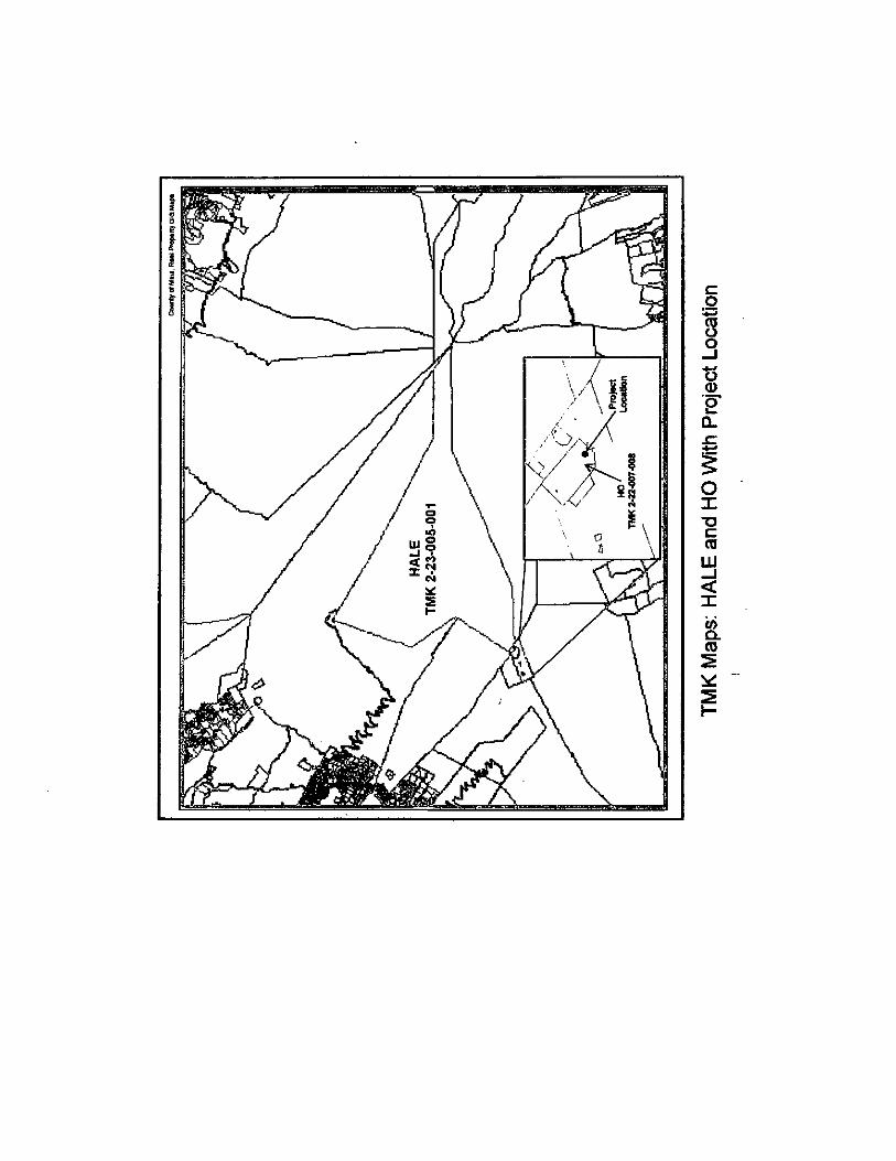
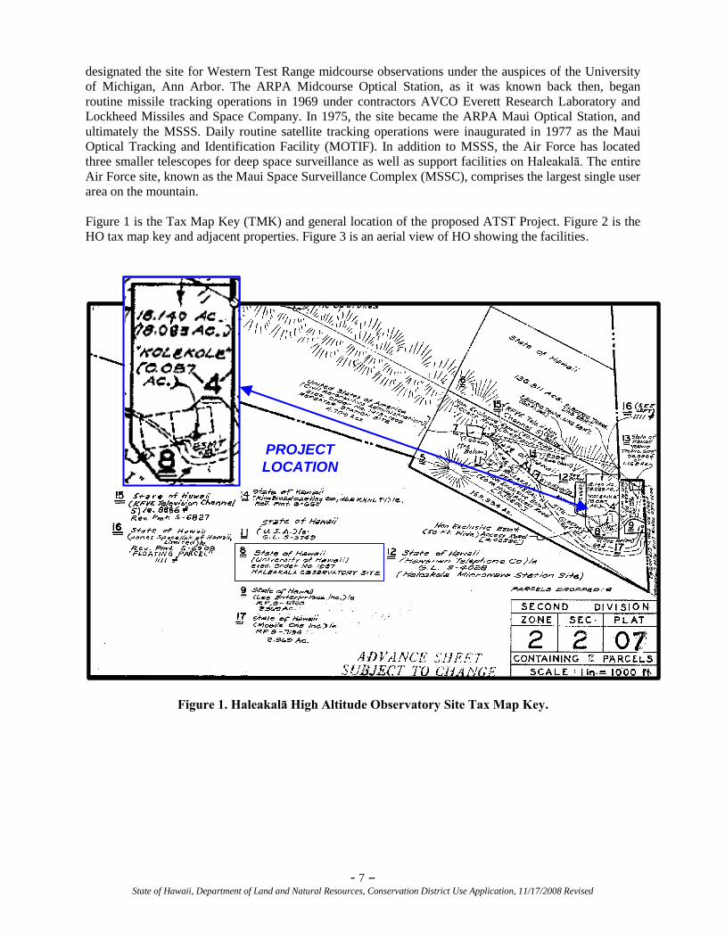
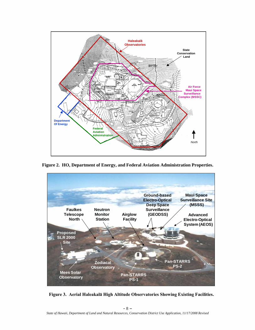
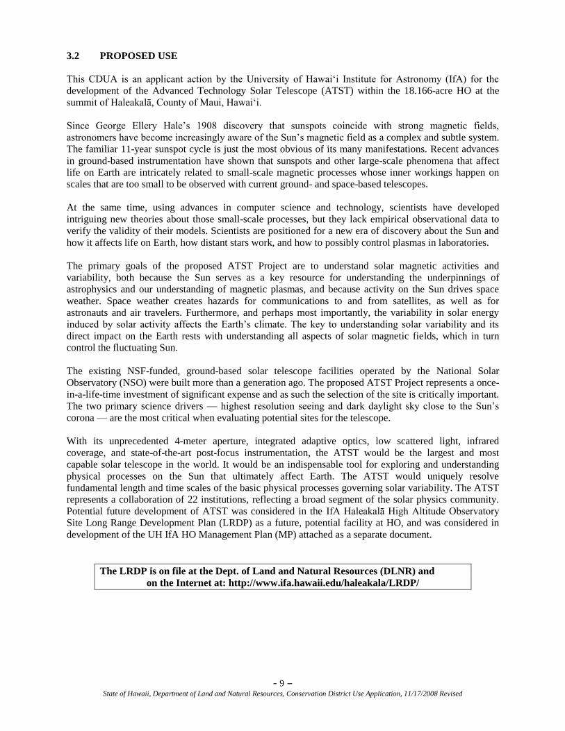
Figure 1 is the Tax Map Key (TMK) and general location of the proposed ATST Project. Figure 2 is the
HO tax map key and adjacent properties. Figure 3 is an aerial view of HO showing the facilities.
Figure 1. Haleakalā High Altitude Observatory Site Tax Map Key.
PROJECT
LOCATION
PROJECT
LOCATION
- 8 – State of Hawaii, Department of Land and Natural Resources, Conservation District Use Application, 11/17/2008 Revised
Figure 2. HO, Department of Energy, and Federal Aviation Administration Properties.
Zodiacal
Observatory
Faulkes
Telescope
North
Neutron
Monitor
Station
Airglow
Facility
Ground-based
Electro-Optical
Deep Space
Surveillance
(GEODSS)
Maui Space
Surveillance Site
(MSSS)
Advanced
Electro-Optical
System (AEOS)
Pan-STARRS
PS-2
Pan-STARRS
PS-1
Mees Solar
Observatory
Proposed
SLR 2000
Site
Figure 3. Aerial Haleakalā High Altitude Observatories Showing Existing Facilities.
State
Conservation
Land
Air Force
Maui Space
Surveillance
Complex (MSSC)
North
Federal
Aviation
Administration
Department
Of Energy
Haleakalā
Observatories
State
Conservation
Land
Air Force
Maui Space
Surveillance
Complex (MSSC)
North
Federal
Aviation
Administration
Department
Of Energy
Haleakalā
Observatories
- 9 – State of Hawaii, Department of Land and Natural Resources, Conservation District Use Application, 11/17/2008 Revised
3.2 PROPOSED USE
This CDUA is an applicant action by the University of Hawai‗i Institute for Astronomy (IfA) for the
development of the Advanced Technology Solar Telescope (ATST) within the 18.166-acre HO at the
summit of Haleakalā, County of Maui, Hawai‗i.
Since George Ellery Hale‘s 1908 discovery that sunspots coincide with strong magnetic fields,
astronomers have become increasingly aware of the Sun‘s magnetic field as a complex and subtle system.
The familiar 11-year sunspot cycle is just the most obvious of its many manifestations. Recent advances
in ground-based instrumentation have shown that sunspots and other large-scale phenomena that affect
life on Earth are intricately related to small-scale magnetic processes whose inner workings happen on
scales that are too small to be observed with current ground- and space-based telescopes.
At the same time, using advances in computer science and technology, scientists have developed
intriguing new theories about those small-scale processes, but they lack empirical observational data to
verify the validity of their models. Scientists are positioned for a new era of discovery about the Sun and
how it affects life on Earth, how distant stars work, and how to possibly control plasmas in laboratories.
The primary goals of the proposed ATST Project are to understand solar magnetic activities and
variability, both because the Sun serves as a key resource for understanding the underpinnings of
astrophysics and our understanding of magnetic plasmas, and because activity on the Sun drives space
weather. Space weather creates hazards for communications to and from satellites, as well as for
astronauts and air travelers. Furthermore, and perhaps most importantly, the variability in solar energy
induced by solar activity affects the Earth‘s climate. The key to understanding solar variability and its
direct impact on the Earth rests with understanding all aspects of solar magnetic fields, which in turn
control the fluctuating Sun.
The existing NSF-funded, ground-based solar telescope facilities operated by the National Solar
Observatory (NSO) were built more than a generation ago. The proposed ATST Project represents a once-
in-a-life-time investment of significant expense and as such the selection of the site is critically important.
The two primary science drivers — highest resolution seeing and dark daylight sky close to the Sun‘s
corona — are the most critical when evaluating potential sites for the telescope.
With its unprecedented 4-meter aperture, integrated adaptive optics, low scattered light, infrared
coverage, and state-of-the-art post-focus instrumentation, the ATST would be the largest and most
capable solar telescope in the world. It would be an indispensable tool for exploring and understanding
physical processes on the Sun that ultimately affect Earth. The ATST would uniquely resolve
fundamental length and time scales of the basic physical processes governing solar variability. The ATST
represents a collaboration of 22 institutions, reflecting a broad segment of the solar physics community.
Potential future development of ATST was considered in the IfA Haleakalā High Altitude Observatory
Site Long Range Development Plan (LRDP) as a future, potential facility at HO, and was considered in
development of the UH IfA HO Management Plan (MP) attached as a separate document.
The LRDP is on file at the Dept. of Land and Natural Resources (DLNR) and
on the Internet at: http://www.ifa.hawaii.edu/haleakala/LRDP/
- 10 – State of Hawaii, Department of Land and Natural Resources, Conservation District Use Application, 11/17/2008 Revised
The ATST Project would construct a reflecting Gregorian-type telescope that would deliver images of the
Sun and the solar corona to instrument stations mounted on the telescope and on a rotating platform
located below the telescope. The ATST facilities would include:
1. The observatory facility, which includes the telescope, its pier, and the rotating instrument
platform,
2. The telescope enclosure,
3. The Support and Operations Building (S&O Building) adjacent to the observatory,
4. A Utility Building attached to the S&O Building by an underground utility chase,
5. Parking for the facility as a whole; and,
6. Modifications to the existing MSO facility.
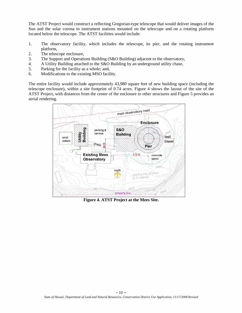
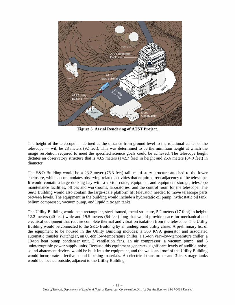
The entire facility would include approximately 43,980 square feet of new building space (including the
telescope enclosure), within a site footprint of 0.74 acres. Figure 4 shows the layout of the site of the
ATST Project, with distances from the center of the enclosure to other structures and Figure 5 provides an
aerial rendering.
Figure 4. ATST Project at the Mees Site.
- 11 – State of Hawaii, Department of Land and Natural Resources, Conservation District Use Application, 11/17/2008 Revised
Existing
MeesObservatory
Pan-STARRS
Solar C
ATST Utility
Building
cistern
ATST Telescope
Enclosure
ATST
S&O Building
Figure 5. Aerial Rendering of ATST Project.
The height of the telescope — defined as the distance from ground level to the rotational center of the
telescope — will be 28 meters (92 feet). This was determined to be the minimum height at which the
image resolution required to meet the specified science goals could be achieved. The telescope height
dictates an observatory structure that is 43.5 meters (142.7 feet) in height and 25.6 meters (84.0 feet) in
diameter.
The S&O Building would be a 23.2 meter (76.3 feet) tall, multi-story structure attached to the lower
enclosure, which accommodates observing-related activities that require direct adjacency to the telescope.
It would contain a large docking bay with a 20-ton crane, equipment and equipment storage, telescope
maintenance facilities, offices and workrooms, laboratories, and the control room for the telescope. The
S&O Building would also contain the large-scale platform lift (elevator) needed to move telescope parts
between levels. The equipment in the building would include a hydrostatic oil pump, hydrostatic oil tank,
helium compressor, vacuum pump, and liquid nitrogen tanks.
The Utility Building would be a rectangular, steel-framed, metal structure, 5.2 meters (17 foot) in height,
12.2 meters (40 feet) wide and 19.5 meters (64 feet) long that would provide space for mechanical and
electrical equipment that require complete thermal and vibration isolation from the telescope. The Utility
Building would be connected to the S&O Building by an underground utility chase. A preliminary list of
the equipment to be housed in the Utility Building includes: a 300 KVA generator and associated
automatic transfer switchgear, an 80-ton low-temperature chiller, a 15-ton very-low-temperature chiller, a
10-ton heat pump condenser unit, 2 ventilation fans, an air compressor, a vacuum pump, and 3
uninterruptible power supply units. Because this equipment generates significant levels of audible noise,
sound-abatement devices would be built into the equipment, and the walls and roof of the Utility Building
would incorporate effective sound blocking materials. An electrical transformer and 3 ice storage tanks
would be located outside, adjacent to the Utility Building.
- 12 – State of Hawaii, Department of Land and Natural Resources, Conservation District Use Application, 11/17/2008 Revised
Additional facilities associated with the telescope facility would include the following:
1. A grounding field consisting of a series of shallow trenches around the facility and fanning out to
the south of the S&O Building filled with conductive concrete or coke breeze (a granular material
with high conductivity) to safely provide an electrical ground for the observatory, which is in an
environment with a high risk of lightning strikes.
2. A wastewater treatment plant with a capacity of 1,000 gallons/day and an associated infiltration
well, designed in compliance with Hawai‗i Department of Health regulations.
3. A stormwater management system including gutters, catchment drains, an underground tank, and
pipes connecting it to the cistern at the MSO facility.
4. A new electrical transformer next to the Utility Building.
5. A diesel generator for use in case of power outages.
With the exception of the Utility Building, the rest of the ATST facility would be white in order to reduce
heat absorption, which would adversely affect telescope operations by heating the adjacent air and
thereby introducing turbulence that would degrade the seeing.
The ATST Project construction would involve land clearing, demolition, grading/leveling, excavation,
soil retention and placement, construction, remodeling of the MSO facility, paving, and other site
improvements. These are discussed in detail in the Final Environmental Impact Statement (FEIS) for the
Advanced Technology Solar Telescope.
3.3 PROJECT LOCATION
The proposed ATST Project would be located on State of Hawai‗i land within the Conservation District
on Pu‗u (hill) Kolekole, near the summit of Haleakalā. Pu‗u Kolekole is about 0.3 miles from the highest
point, Pu‗u Ula‗ula (Red Hill) Overlook, which is in Haleakalā National Park (HALE). At an elevation of
10,023 feet, Haleakalā is one of the prime sites in the world for astronomical and space surveillance
activities. The Kolekole cinder cone lies near the apex of the Southwest rift zone of the mountain. The rift
zone forms a spine separating the Kula Forest Reserve from the Kahikinui Forest Reserve, both of which
are pristine lands along the rift zone.
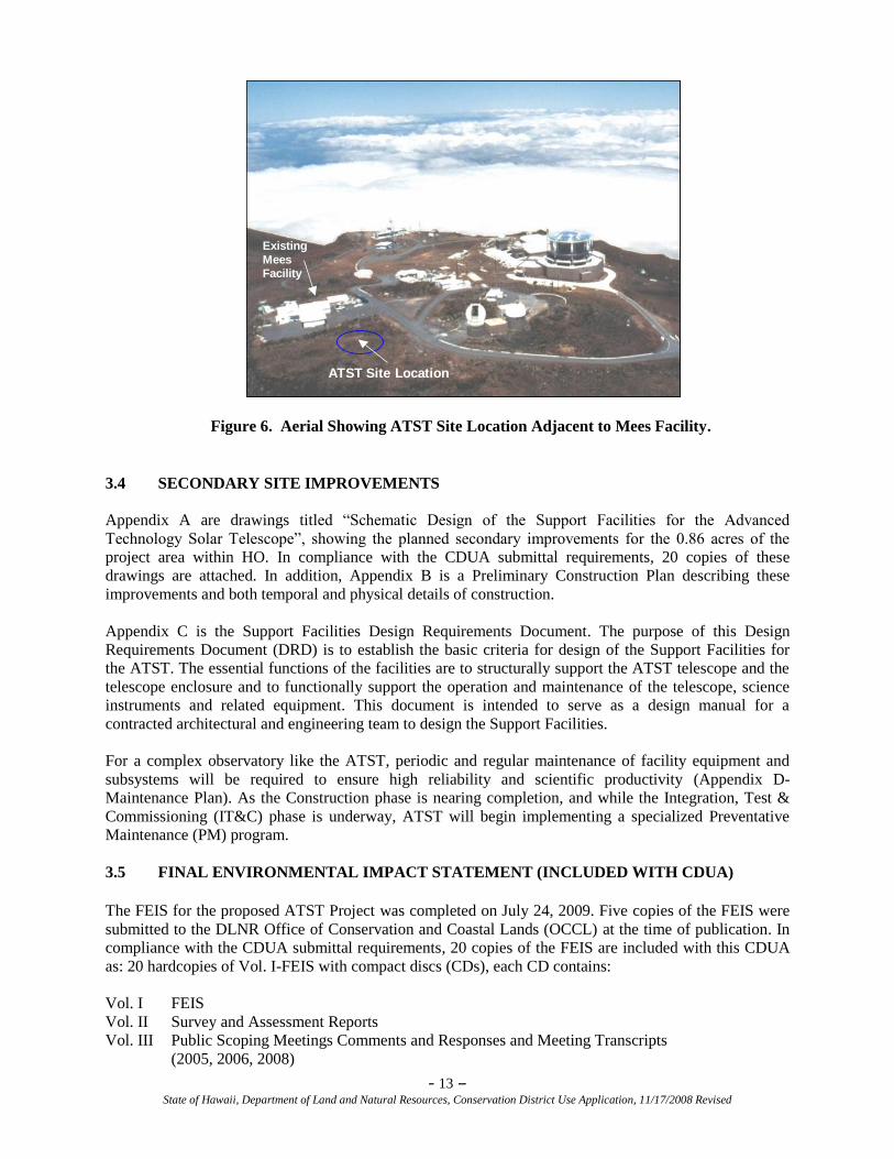
The proposed ATST Project would be located within HO at the summit of Haleakalā, County of Maui,
Hawai‗i, on approximately 0.86 acres of undeveloped, but mostly previously disturbed, land. The 0.86
acres includes the leveling area, buildings, and paved pads (the actual building footprint would be 0.74
acres). The proposed ATST Project site would be east of the existing C. E. Kenneth Mees Solar
Observatory (MSO) facility (Fig. 6).
- 13 – State of Hawaii, Department of Land and Natural Resources, Conservation District Use Application, 11/17/2008 Revised
Mees Location
Reber Circle
Location
Existing
Mees Facility
ATST Site Location
Existing
Mees Facility
Figure 6. Aerial Showing ATST Site Location Adjacent to Mees Facility.
3.4 SECONDARY SITE IMPROVEMENTS
Appendix A are drawings titled ―Schematic Design of the Support Facilities for the Advanced
Technology Solar Telescope‖, showing the planned secondary improvements for the 0.86 acres of the
project area within HO. In compliance with the CDUA submittal requirements, 20 copies of these
drawings are attached. In addition, Appendix B is a Preliminary Construction Plan describing these
improvements and both temporal and physical details of construction.
Appendix C is the Support Facilities Design Requirements Document. The purpose of this Design
Requirements Document (DRD) is to establish the basic criteria for design of the Support Facilities for
the ATST. The essential functions of the facilities are to structurally support the ATST telescope and the
telescope enclosure and to functionally support the operation and maintenance of the telescope, science
instruments and related equipment. This document is intended to serve as a design manual for a
contracted architectural and engineering team to design the Support Facilities.
For a complex observatory like the ATST, periodic and regular maintenance of facility equipment and
subsystems will be required to ensure high reliability and scientific productivity (Appendix D-
Maintenance Plan). As the Construction phase is nearing completion, and while the Integration, Test &
Commissioning (IT&C) phase is underway, ATST will begin implementing a specialized Preventative
Maintenance (PM) program.
3.5 FINAL ENVIRONMENTAL IMPACT STATEMENT (INCLUDED WITH CDUA)
The FEIS for the proposed ATST Project was completed on July 24, 2009. Five copies of the FEIS were
submitted to the DLNR Office of Conservation and Coastal Lands (OCCL) at the time of publication. In
compliance with the CDUA submittal requirements, 20 copies of the FEIS are included with this CDUA
as: 20 hardcopies of Vol. I-FEIS with compact discs (CDs), each CD contains:
Vol. I FEIS
Vol. II Survey and Assessment Reports
Vol. III Public Scoping Meetings Comments and Responses and Meeting Transcripts
(2005, 2006, 2008)
- 14 – State of Hawaii, Department of Land and Natural Resources, Conservation District Use Application, 11/17/2008 Revised
Vol. IV Public Comments and Responses to Draft EIS (September 2006) and
Supplemental Draft EIS (May 2009); SDEIS Public Hearing Transcripts (June 2009);
Facilitator‘s Notes Section 106 Consultation Meetings (June 2009)
3.6 UH IfA HALEAKALĀ HIGH ALTITUDE OBSERVATORY SITE
MANAGEMENT PLAN (SEPARATE DOCUMENT)
A Management Plan (MP) for HO was prepared in accordance with Hawai‗i Administrative Rules (HAR)
Chapter 13: Department of Land and Natural Resources (DLNR), Subtitle 1: Administration, Chapter 5:
Conservation District, where this document is implemented to regulate land use in the Conservation
District for the purpose of conserving, protecting, and preserving the important natural resources of the
State through appropriate management and use to promote their long term sustainability and the public
health, safety, and welfare. ―Management plan‖ means a comprehensive plan for carrying out multiple
land uses (HAR §13-5-2).
HO is not a multiple land use property. HO is a single land use property, in accordance with Executive
Order (EO) 1987, which designated the land for use by HO, and no additional purposes. Therefore an MP
may not be required by the HAR. However, the MP is intended to assist IfA to meet the General
Provisions of Chapter 13-5-1 above.
3.7 UH IfA LONG RANGE DEVELOPMENT PLAN (ON FILE AT DLNR)
The University of Hawai‗i Institute for Astronomy LRDP, published in January 2005, is a publicly vetted
document that describes the general environmental, cultural, and historic conditions and the site
characteristics that guide future development. It also describes the principles that define the scientific
programs that the UH strives to maintain and develop at HO and the potential new facility developments
that will keep the UH in the forefront of astronomy into the next decade. In order to describe and to
protect this resource, while accommodating the growing need for public scrutiny and partnering in its
astronomical planning, the IfA planning process for long-range development takes into consideration the
environmental, cultural, and historic importance of Haleakalā.
While the long range planning aspect of the LRDP is current,
the management plans for HO that were included in the LRDP
are superseded by the management plans in the MP attached to this CDUA.
4.0 CONSERVATION DISTRICT REQUIREMENTS
4.1 Demonstrate that the proposed use is consistent with the following criteria. Refer to HAR,
Section 13-5-30, to review criteria. Attach additional sheets if necessary.
In accordance with HAR 13-5-30, the application is consistent with Conservation District requirements,
as described in the following paragraphs.
4.2 Is the proposed land use consistent with the purpose of the Conservation District?
The proposed land use is consistent with the purpose of the Conservation District.
The objective of the Conservation District is to conserve, protect, and preserve the important natural
resources of the State through appropriate management and use to promote their long-term sustainability
and the public health, safety, and welfare. The proposed ATST Project is consistent with the intention that
conveyed HO to the University of Hawai‗i by Governor‘s Executive Order 1987, where ―…the lands
- 15 – State of Hawaii, Department of Land and Natural Resources, Conservation District Use Application, 11/17/2008 Revised
herein set aside shall be used for the Haleakalā High Altitude Observatory Site purposes only.‖ Many
facilities conducting astronomy and advanced space surveillance already exist in HO.
4.3 Is the proposed use consistent with the objectives of the subzone of the land in which the use
will occur?
The proposed land use is consistent with the objectives of the Subzone of the land on which the use will
occur.
The existing State Land Use District for the proposed ATST Project is designated as Conservation
District, General Subzone. The objective of the General Subzone is to designate open space where
specific conservation uses may not be defined, but where urban use would be premature. During the past
few years, the OCCL within the DLNR has administered CDUPs for numerous potential uses, among
them astronomical facilities on Haleakalā. The Proposed Action would be located in the area of the
Conservation District that has been set aside for astronomical research (§13-5-25: Identified land uses in
the General Subzone, which is applicable from R-3 Astronomy Facilities, (D-1) Astronomy facilities
under an approved management plan).
4.4 Does the proposed land use comply with provisions and guidelines contained in Chapter
205A, Hawaii Revised Statutes (HRS), entitled “Coastal Zone Management,” where
applicable?
The proposed land use complies with the provisions and guidelines contained in Chapter 205A, HRS,
entitled Coastal Zone Management, where applicable.
To determine whether HO falls in the Coastal Zone Management area, reference was made to the County
of Maui Planning Department map entitled Island of Maui Showing Special Management Area provided
by the County of Maui GIS Program Office of the Managing Director, dated July 2002, and located in the
Zoning and Administration Enforcement Division of the Planning Department, Wailuku, Maui. The map
clearly indicates that the ATST facility would be located in the HO complex and is not in the Coastal
Zone Management area.
The Kilohana Map M-11, State Land Use Designation Map (Conservation District topography map)
located in the same County office verifies that the subject parcel is not within the Special Management
Area (June 1995, State of Hawai‗i Land Use Commission).
4.5 Describe how the proposed land use will not cause substantial adverse impact to existing
natural resources within the surrounding area, community or region.
The existing natural resources are described in Section 5.1 and 6.6 of this CDUA. The potential impacts
on natural resources of the proposed ATST Project were carefully evaluated during four-year long
National Environmental Policy Act (NEPA) and National Historic Preservation Act (NHPA) assessment
processes, culminating in the attached joint Federal and State FEIS, published in July 2009.
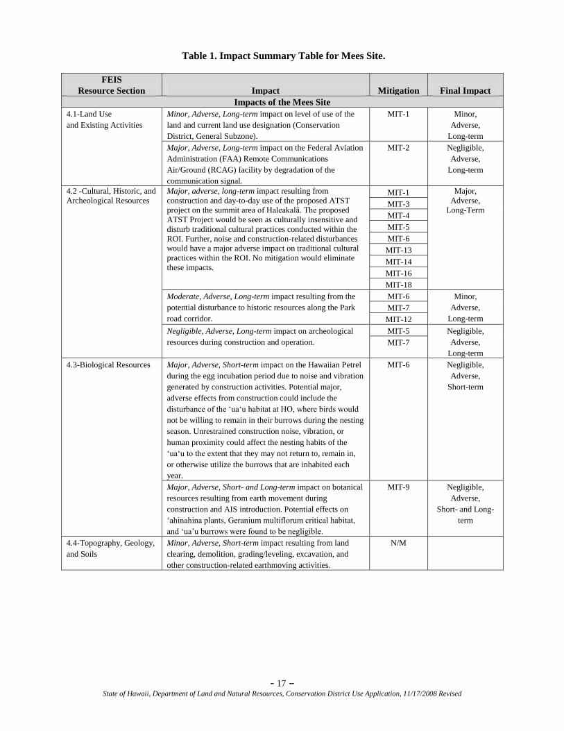
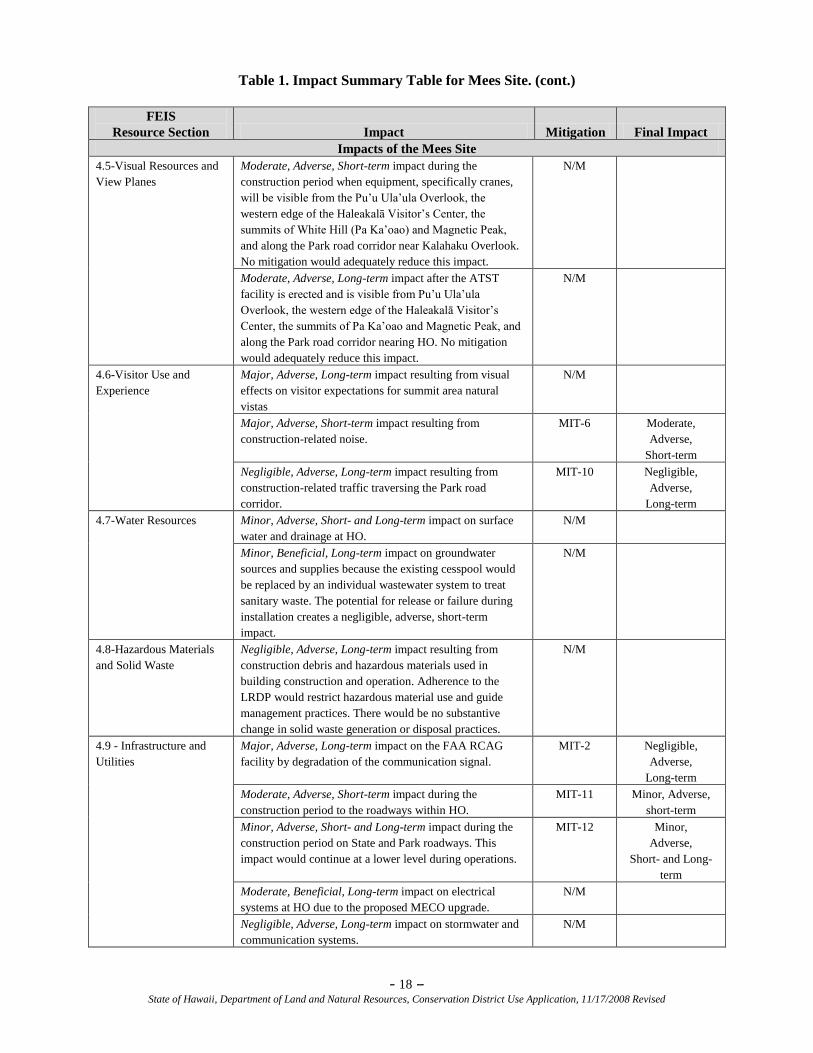
The criteria for the intensity of impact on each resource, the anticipated impacts on the natural
environment, and mitigations for those impacts are described in FEIS Volume I Section 4.0-
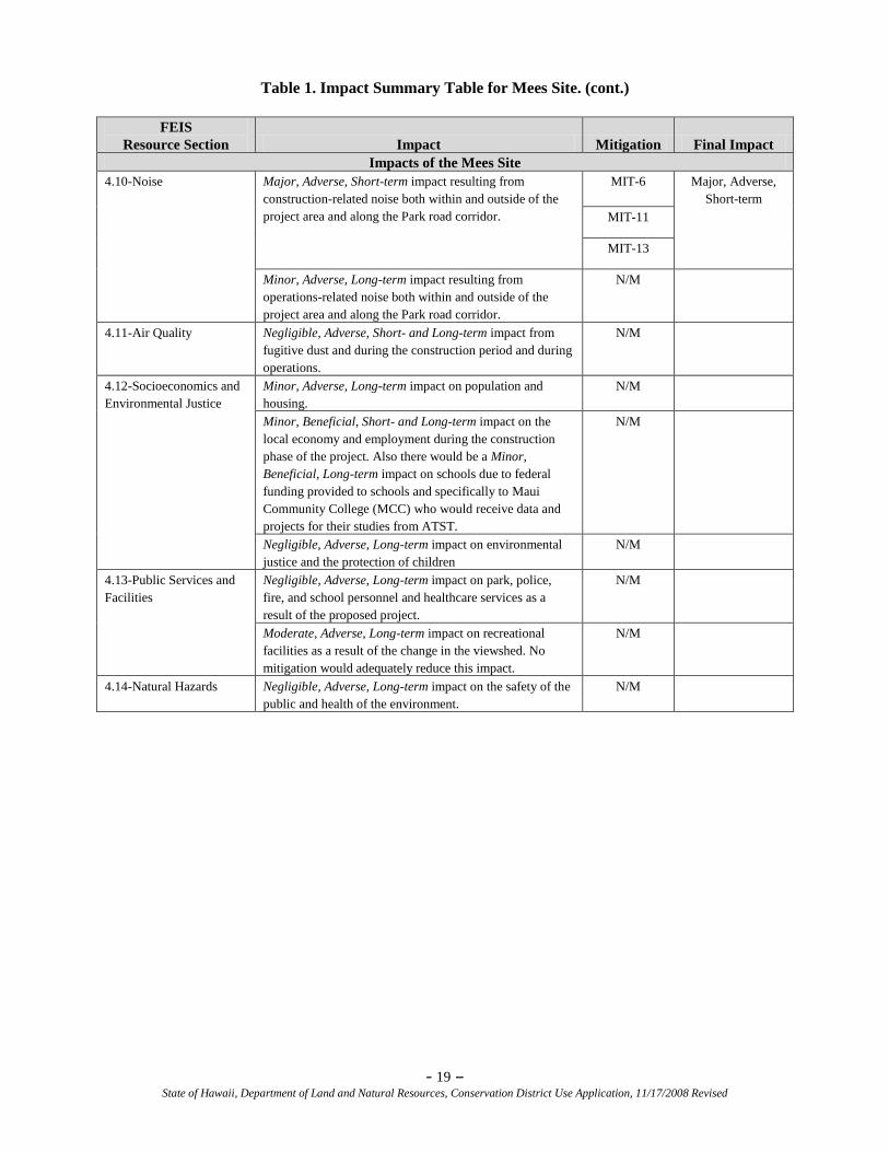
Environmental Consequences, Cumulative Impacts, and Mitigation. Table 1 below is a summary of the
resources, impacts, mitigations, and final impacts for the Mees Site (shown in FEIS Vol. I as Table 4-7.)
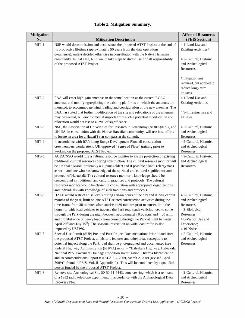
Table 2 below details the mitigations for those impacts (shown in FEIS Vol. I as Table 4-13) Within the
FEIS, potential impacts were characterized with respect to intensities described as major, moderate,
minor, and negligible.
- 16 – State of Hawaii, Department of Land and Natural Resources, Conservation District Use Application, 11/17/2008 Revised
Both Tables 1 and 2 below show that the proposed ATST Project would have a substantial (major)
adverse impact on cultural resources. Specifically, the proposed ATST Project would be seen as culturally
insensitive and disturb traditional cultural practices conducted within the Region of Influence (ROI),
which includes parts of HALE. Noise and associated construction-related disturbances would also have a
major, adverse impact on traditional cultural practices within the ROI. No mitigation would eliminate
these impacts, but numerous mitigation measures would be employed to reduce such impacts as much as
possible. As shown from the extensive analysis conducted during the EIS process, no other aspects of the
proposed land use would result in substantial (major) adverse impacts.
Volume II of the FEIS consists of numerous studies, inventories, surveys, and evaluations of resources
and potential impacts on those resources within HO, the surrounding area, community or region. Volume
III of the FEIS consists of the Public Scoping Meetings, Comments and Responses and Meeting
Transcripts (2005, 2006, 2008). Volume IV is a continuation of the content in Volume III to include 2009,
along with Facilitator Notes from Section 106 meetings in 2009.
- 17 – State of Hawaii, Department of Land and Natural Resources, Conservation District Use Application, 11/17/2008 Revised
Table 1. Impact Summary Table for Mees Site.
FEIS
Resource Section Impact Mitigation Final Impact
Impacts of the Mees Site
4.1-Land Use
and Existing Activities
Minor, Adverse, Long-term impact on level of use of the
land and current land use designation (Conservation
District, General Subzone).
MIT-1 Minor,
Adverse,
Long-term
Major, Adverse, Long-term impact on the Federal Aviation
Administration (FAA) Remote Communications
Air/Ground (RCAG) facility by degradation of the
communication signal.
MIT-2 Negligible,
Adverse,
Long-term
4.2 -Cultural, Historic, and
Archeological Resources
Major, adverse, long-term impact resulting from
construction and day-to-day use of the proposed ATST
project on the summit area of Haleakalā. The proposed
ATST Project would be seen as culturally insensitive and
disturb traditional cultural practices conducted within the
ROI. Further, noise and construction-related disturbances
would have a major adverse impact on traditional cultural
practices within the ROI. No mitigation would eliminate
these impacts.
MIT-1 Major,
Adverse,
Long-Term
MIT-3
MIT-4
MIT-5
MIT-6
MIT-13
MIT-14
MIT-16
MIT-18
Moderate, Adverse, Long-term impact resulting from the
potential disturbance to historic resources along the Park
road corridor.
MIT-6 Minor,
Adverse,
Long-term
MIT-7
MIT-12
Negligible, Adverse, Long-term impact on archeological
resources during construction and operation.
MIT-5 Negligible,
Adverse,
Long-term
MIT-7
4.3-Biological Resources Major, Adverse, Short-term impact on the Hawaiian Petrel
during the egg incubation period due to noise and vibration
generated by construction activities. Potential major,
adverse effects from construction could include the
disturbance of the ‗ua‗u habitat at HO, where birds would
not be willing to remain in their burrows during the nesting
season. Unrestrained construction noise, vibration, or
human proximity could affect the nesting habits of the
‗ua‗u to the extent that they may not return to, remain in,
or otherwise utilize the burrows that are inhabited each
year.
MIT-6 Negligible,
Adverse,
Short-term
Major, Adverse, Short- and Long-term impact on botanical
resources resulting from earth movement during
construction and AIS introduction. Potential effects on
‗ahinahina plants, Geranium multiflorum critical habitat,
and ‗ua‘u burrows were found to be negligible.
MIT-9 Negligible,
Adverse,
Short- and Long-
term
4.4-Topography, Geology,
and Soils
Minor, Adverse, Short-term impact resulting from land
clearing, demolition, grading/leveling, excavation, and
other construction-related earthmoving activities.
N/M
- 18 – State of Hawaii, Department of Land and Natural Resources, Conservation District Use Application, 11/17/2008 Revised
Table 1. Impact Summary Table for Mees Site. (cont.)
FEIS
Resource Section Impact Mitigation Final Impact
Impacts of the Mees Site
4.5-Visual Resources and
View Planes
Moderate, Adverse, Short-term impact during the
construction period when equipment, specifically cranes,
will be visible from the Pu‘u Ula‘ula Overlook, the
western edge of the Haleakalā Visitor‘s Center, the
summits of White Hill (Pa Ka‘oao) and Magnetic Peak,
and along the Park road corridor near Kalahaku Overlook.
No mitigation would adequately reduce this impact.
N/M
Moderate, Adverse, Long-term impact after the ATST
facility is erected and is visible from Pu‘u Ula‘ula
Overlook, the western edge of the Haleakalā Visitor‘s
Center, the summits of Pa Ka‘oao and Magnetic Peak, and
along the Park road corridor nearing HO. No mitigation
would adequately reduce this impact.
N/M
4.6-Visitor Use and
Experience
Major, Adverse, Long-term impact resulting from visual
effects on visitor expectations for summit area natural
vistas
N/M
Major, Adverse, Short-term impact resulting from
construction-related noise.
MIT-6
Moderate,
Adverse,
Short-term
Negligible, Adverse, Long-term impact resulting from
construction-related traffic traversing the Park road
corridor.
MIT-10 Negligible,
Adverse,
Long-term
4.7-Water Resources Minor, Adverse, Short- and Long-term impact on surface
water and drainage at HO.
N/M
Minor, Beneficial, Long-term impact on groundwater
sources and supplies because the existing cesspool would
be replaced by an individual wastewater system to treat
sanitary waste. The potential for release or failure during
installation creates a negligible, adverse, short-term
impact.
N/M
4.8-Hazardous Materials
and Solid Waste
Negligible, Adverse, Long-term impact resulting from
construction debris and hazardous materials used in
building construction and operation. Adherence to the
LRDP would restrict hazardous material use and guide
management practices. There would be no substantive
change in solid waste generation or disposal practices.
N/M
4.9 - Infrastructure and
Utilities
Major, Adverse, Long-term impact on the FAA RCAG
facility by degradation of the communication signal.
MIT-2 Negligible,
Adverse,
Long-term
Moderate, Adverse, Short-term impact during the
construction period to the roadways within HO.
MIT-11 Minor, Adverse,
short-term
Minor, Adverse, Short- and Long-term impact during the
construction period on State and Park roadways. This
impact would continue at a lower level during operations.
MIT-12 Minor,
Adverse,
Short- and Long-
term
Moderate, Beneficial, Long-term impact on electrical
systems at HO due to the proposed MECO upgrade.
N/M
Negligible, Adverse, Long-term impact on stormwater and
communication systems.
N/M
- 19 – State of Hawaii, Department of Land and Natural Resources, Conservation District Use Application, 11/17/2008 Revised
Table 1. Impact Summary Table for Mees Site. (cont.)
FEIS
Resource Section Impact Mitigation Final Impact
Impacts of the Mees Site
4.10-Noise Major, Adverse, Short-term impact resulting from
construction-related noise both within and outside of the
project area and along the Park road corridor.
MIT-6
Major, Adverse,
Short-term
MIT-11
MIT-13
Minor, Adverse, Long-term impact resulting from
operations-related noise both within and outside of the
project area and along the Park road corridor.
N/M
4.11-Air Quality Negligible, Adverse, Short- and Long-term impact from
fugitive dust and during the construction period and during
operations.
N/M
4.12-Socioeconomics and
Environmental Justice
Minor, Adverse, Long-term impact on population and
housing.
N/M
Minor, Beneficial, Short- and Long-term impact on the
local economy and employment during the construction
phase of the project. Also there would be a Minor,
Beneficial, Long-term impact on schools due to federal
funding provided to schools and specifically to Maui
Community College (MCC) who would receive data and
projects for their studies from ATST.
N/M
Negligible, Adverse, Long-term impact on environmental
justice and the protection of children
N/M
4.13-Public Services and
Facilities
Negligible, Adverse, Long-term impact on park, police,
fire, and school personnel and healthcare services as a
result of the proposed project.
N/M
Moderate, Adverse, Long-term impact on recreational
facilities as a result of the change in the viewshed. No
mitigation would adequately reduce this impact.
N/M
4.14-Natural Hazards Negligible, Adverse, Long-term impact on the safety of the
public and health of the environment.
N/M
- 20 – State of Hawaii, Department of Land and Natural Resources, Conservation District Use Application, 11/17/2008 Revised
Table 2. Mitigation Summary.
Mitigation
No. Mitigation Description
Affected Resources
(FEIS Section)
MIT-1 NSF would decommission and deconstruct the proposed ATST Project at the end of
its productive lifetime (approximately 50 years from the date operations
commence), unless decided otherwise in consultation with the Native Hawaiian
community. In that case, NSF would take steps to divest itself of all responsibility
of the proposed ATST Project.
4.1-Land Use and
Existing Activities*
4.2-Cultural, Historic,
and Archeological
Resources
*mitigation not
required, but applied to
reduce long- term
impacts
MIT-2 FAA will erect high-gain antennas in the same location as the current RCAG
antennas and modifying/replacing the existing platforms on which the antennas are
mounted, to accommodate wind loading and configuration of the new antennas. The
FAA has stated that further modification of the site and relocations of the antennas
may be needed, but environmental impacts from such a potential modification and
relocation would not rise to a level of significance.
4.1-Land Use and
Existing Activities
4.9-Infrastructure and
Utilities
MIT-3 NSF, the Association of Universities for Research in Astronomy (AURA)/NSO, and
UH IfA, in consultation with the Native Hawaiian community, will use best efforts
to locate an area for a Hawai‗i star compass at the summit.
4.2-Cultural, Historic,
and Archeological
Resources
MIT-4 In accordance with IfA‘s Long Range Development Plan, all construction
crewmembers would attend UH-approved ―Sense of Place‖ training prior to
working on the proposed ATST Project.
4.2-Cultural, Historic,
and Archeological
Resources
MIT-5 AURA/NSO would hire a cultural resource monitor to ensure protection of existing
traditional cultural resources during construction. The cultural resource monitor will
be a Kanaka Maoli, preferably a kupuna (elder) and if possible a kahu (clergyman)
as well, and one who has knowledge of the spiritual and cultural significance and
protocol of Haleakalā. The cultural resource monitor‘s knowledge should be
concentrated in traditional and cultural practices and protocols. The cultural
resources monitor would be chosen in consultation with appropriate organizations
and individuals with knowledge of such traditions and protocols.
4.2-Cultural, Historic,
and Archeological
Resources
MIT-6 HALE would restrict noise levels during certain hours of the day and during certain
months of the year, limit on-site ATST-related construction activities during the
time-frame from 30 minutes after sunrise to 30 minutes prior to sunset, limit the
hours for wide load vehicles to traverse the Park road (such vehicles need to come
through the Park during the night between approximately 8:00 p.m. and 4:00 a.m.,
and prohibit wide or heavy loads from coming through the Park at night between
April 20th and July 15th). The seasonal restriction on wide load traffic is also
imposed by USFWS.
4.2-Cultural, Historic,
and Archeological
Resources;
4.3-Biological
Resources;
4.6-Visitor Use and
Experience;
4.10-Noise
MIT-7 Special Use Permit (SUP) Pre- and Post-Project Documentation: Prior to and after
the proposed ATST Project, all historic features and other areas susceptible to
potential impact along the Park road shall be photographed and documented (see
Federal Highway Administration (FHWA) report – ―Haleakala Highway, Haleakala
National Park, Pavement Drainage Condition Investigation, Distress Identification
and Recommendations Report # HALA 3-2-2009, March 2, 2009 (revised April
2009)‖, found in FEIS, Vol. II-Appendix P). This will be completed by a qualified
person funded by the proposed ATST Project.
4.2-Cultural, Historic,
and Archeological
Resources
MIT-8 Remove site Archeological Site 50-50-11-5443, concrete ring, which is a remnant
of a 1952 radio telescope experiment, in accordance with the Archaeological Data
Recovery Plan.
4.2-Cultural, Historic,
and Archeological
Resources
- 21 – State of Hawaii, Department of Land and Natural Resources, Conservation District Use Application, 11/17/2008 Revised
Table 2. Mitigation Summary (cont.).
Mitigation
No. Mitigation Description
Affected Resources
(FEIS Section)
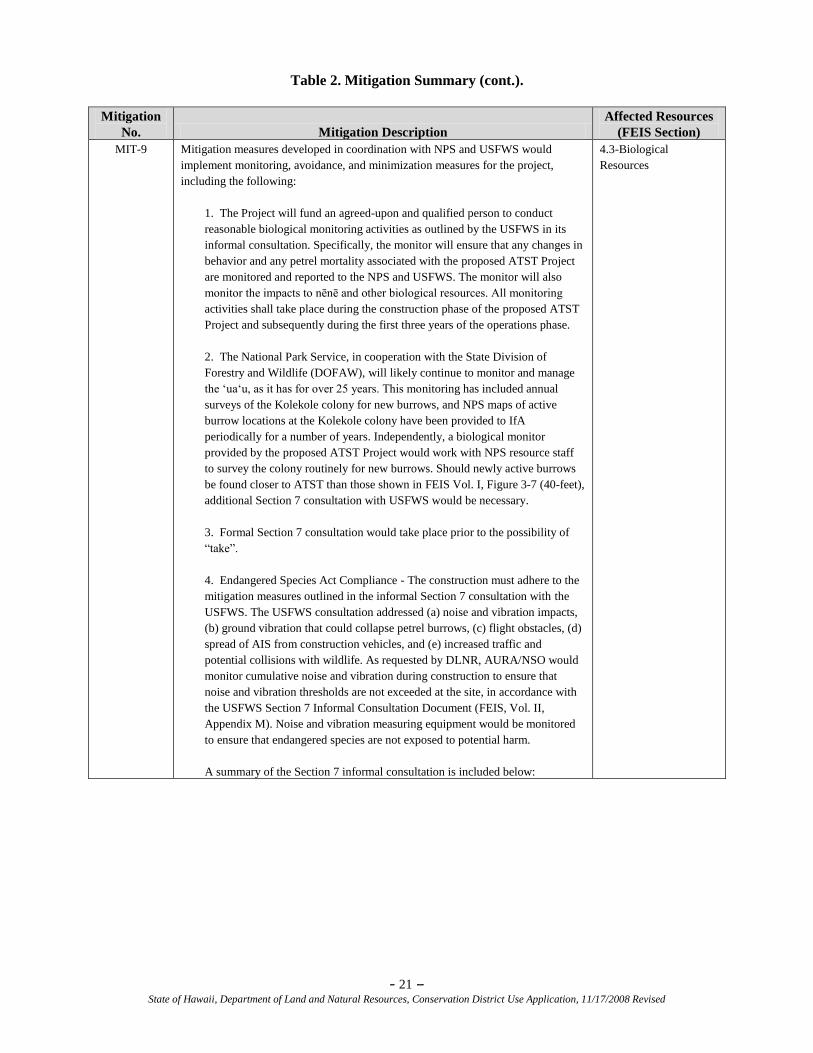
MIT-9 Mitigation measures developed in coordination with NPS and USFWS would
implement monitoring, avoidance, and minimization measures for the project,
including the following:
1. The Project will fund an agreed-upon and qualified person to conduct
reasonable biological monitoring activities as outlined by the USFWS in its
informal consultation. Specifically, the monitor will ensure that any changes in
behavior and any petrel mortality associated with the proposed ATST Project
are monitored and reported to the NPS and USFWS. The monitor will also
monitor the impacts to nēnē and other biological resources. All monitoring
activities shall take place during the construction phase of the proposed ATST
Project and subsequently during the first three years of the operations phase.
2. The National Park Service, in cooperation with the State Division of
Forestry and Wildlife (DOFAW), will likely continue to monitor and manage
the ‗ua‗u, as it has for over 25 years. This monitoring has included annual
surveys of the Kolekole colony for new burrows, and NPS maps of active
burrow locations at the Kolekole colony have been provided to IfA
periodically for a number of years. Independently, a biological monitor
provided by the proposed ATST Project would work with NPS resource staff
to survey the colony routinely for new burrows. Should newly active burrows
be found closer to ATST than those shown in FEIS Vol. I, Figure 3-7 (40-feet),
additional Section 7 consultation with USFWS would be necessary.
3. Formal Section 7 consultation would take place prior to the possibility of
―take‖.
4. Endangered Species Act Compliance - The construction must adhere to the
mitigation measures outlined in the informal Section 7 consultation with the
USFWS. The USFWS consultation addressed (a) noise and vibration impacts,
(b) ground vibration that could collapse petrel burrows, (c) flight obstacles, (d)
spread of AIS from construction vehicles, and (e) increased traffic and
potential collisions with wildlife. As requested by DLNR, AURA/NSO would
monitor cumulative noise and vibration during construction to ensure that
noise and vibration thresholds are not exceeded at the site, in accordance with
the USFWS Section 7 Informal Consultation Document (FEIS, Vol. II,
Appendix M). Noise and vibration measuring equipment would be monitored
to ensure that endangered species are not exposed to potential harm.
A summary of the Section 7 informal consultation is included below:
4.3-Biological
Resources
- 22 – State of Hawaii, Department of Land and Natural Resources, Conservation District Use Application, 11/17/2008 Revised
Table 2. Mitigation Summary (cont.).
Mitigation
No. Mitigation Description
Affected Resources
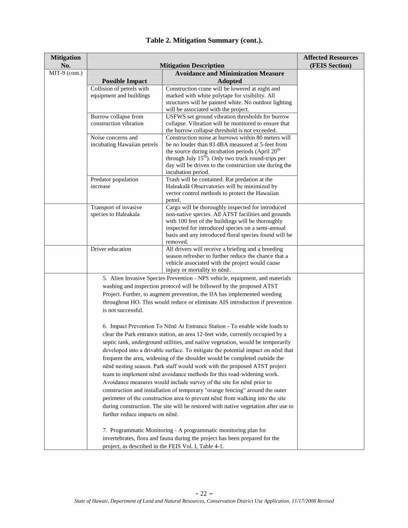
(FEIS Section) MIT-9 (cont.)
Possible Impact
Avoidance and Minimization Measure
Adopted
Collision of petrels with
equipment and buildings
Construction crane will be lowered at night and
marked with white polytape for visibility. All
structures will be painted white. No outdoor lighting
will be associated with the project.
Burrow collapse from
construction vibration
USFWS set ground vibration thresholds for burrow
collapse. Vibration will be monitored to ensure that
the burrow collapse threshold is not exceeded.
Noise concerns and
incubating Hawaiian petrels
Construction noise at burrows within 80 meters will
be no louder than 83 dBA measured at 5-feet from
the source during incubation periods (April 20th
through July 15th). Only two truck round-trips per
day will be driven to the construction site during the
incubation period.
Predator population
increase
Trash will be contained. Rat predation at the
Haleakalā Observatories will be minimized by
vector control methods to protect the Hawaiian
petrel.
Transport of invasive
species to Haleakala
Cargo will be thoroughly inspected for introduced
non-native species. All ATST facilities and grounds
with 100 feet of the buildings will be thoroughly
inspected for introduced species on a semi-annual
basis and any introduced floral species found will be
removed.
Driver education All drivers will receive a briefing and a breeding
season refresher to further reduce the chance that a
vehicle associated with the project would cause
injury or mortality to nēnē.
5. Alien Invasive Species Prevention - NPS vehicle, equipment, and materials
washing and inspection protocol will be followed by the proposed ATST
Project. Further, to augment prevention, the IfA has implemented weeding
throughout HO. This would reduce or eliminate AIS introduction if prevention
is not successful.
6. Impact Prevention To Nēnē At Entrance Station - To enable wide loads to
clear the Park entrance station, an area 12-feet wide, currently occupied by a
septic tank, underground utilities, and native vegetation, would be temporarily
developed into a drivable surface. To mitigate the potential impact on nēnē that
frequent the area, widening of the shoulder would be completed outside the
nēnē nesting season. Park staff would work with the proposed ATST project
team to implement nēnē avoidance methods for this road-widening work.
Avoidance measures would include survey of the site for nēnē prior to
construction and installation of temporary "orange fencing" around the outer
perimeter of the construction area to prevent nēnē from walking into the site
during construction. The site will be restored with native vegetation after use to
further reduce impacts on nēnē.
7. Programmatic Monitoring - A programmatic monitoring plan for
invertebrates, flora and fauna during the project has been prepared for the
project, as described in the FEIS Vol. I, Table 4-1.
- 23 – State of Hawaii, Department of Land and Natural Resources, Conservation District Use Application, 11/17/2008 Revised
Table 2. Mitigation Summary (cont.).
Mitigation
No. Mitigation Description
Affected Resources
(FEIS Section)
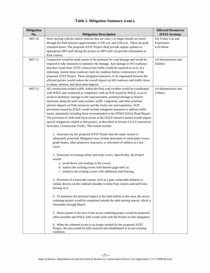
MIT-10 Slow moving vehicles and/or vehicles that are class 5 or larger should not travel
through the Park between approximately 11:00 a.m. and 2:00 p.m. These are peak
visitation hours. The proposed ATST Project shall provide regular updates to
appropriate NPS staff during the project so NPS staff can provide information to
Park visitors.
4.6-Visitor Use and
Experience;
4.10-Noise
MIT-11 Contractors would be made aware of the potential for road damage and would be
required to take measures to minimize the damage. Any damage to HO roadways
that does result from ATST construction traffic would be repaired so as to, at a
minimum, restore those roadways back its condition before construction of the
proposed ATST Project. These mitigation measures, to be negotiated between the
affected parties, would reduce the overall impact on HO roadways and traffic down
to minor, adverse, and short-term impacts.
4.9-Infrastructure and
Utilities
MIT-12 All construction-related traffic within the Park road corridor would be coordinated
with HALE and conducted in compliance with an SUP issued by HALE, so as to
avoid or minimize: damage to the road pavement, potential damage to historic
structures along the park road corridor, traffic congestion, and other potential
adverse impacts on Park resources and the visitor use and experience. SUP
provisions issued by HALE would include mitigation measures to address traffic
issues, potentially including those recommended in the FHWA HALE Road Report.
The provision of wide-load truck access at the HALE entrance station would require
special mitigations related to that project, as described in Section 2.4.3-Construction
Activities, Construction Traffic. This would include:
1. Assurance by the proposed ATST Project that the septic system is
adequately protected. Mitigation may include placement of metal plate covers,
grade beams, other protective structures, or relocation of utilities as a last
resort.
2. Protection of existing utility man-hole covers. Specifically, the Project
would:
a. avoid direct axle loading on the covers,
b. replace the existing covers with heavier gage steel; or,
c. reinforce the existing covers with additional steel bracing.
3. Provision of a barricade system, such as a gate, removable bollards or
similar devices on the widened shoulder to deter Park visitors and staff from
driving on it.
4. To minimize the potential impact to the nēnē habitat in this area, the access
widening project would be completed outside the nēnē nesting season, which is
November through March.
5. Native plants in the area of the access widening project would be protected
when possible and HALE staff would work with the Project on this mitigation.
6. When the widened access is no longer needed for the proposed ATST
Project, the area would be fully restored and rehabilitated to its pre-existing
condition.
4.9-Infrastructure and
Utilities
- 24 – State of Hawaii, Department of Land and Natural Resources, Conservation District Use Application, 11/17/2008 Revised
Table 2. Mitigation Summary (cont.).
Mitigation
No. Mitigation Description
Affected Resources
(FEIS Section)
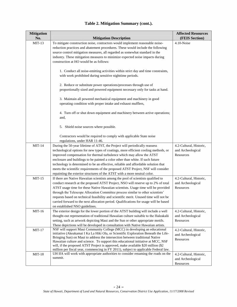
MIT-13 To mitigate construction noise, contractors would implement reasonable noise-
reduction practices and abatement procedures. These would include the following
source control mitigation measures, all regarded as somewhat standard in the
industry. These mitigation measures to minimize expected noise impacts during
construction at HO would be as follows:
1. Conduct all noise-emitting activities within strict day and time constraints,
with work prohibited during sensitive nighttime periods.
2. Reduce or substitute power operations/processes through use of
proportionally sized and powered equipment necessary only for tasks at hand.
3. Maintain all powered mechanical equipment and machinery in good
operating condition with proper intake and exhaust mufflers,
4. Turn off or shut down equipment and machinery between active operations;
and,
5. Shield noise sources where possible.
Contractors would be required to comply with applicable State noise
regulations, under HAR 11-46.
4.10-Noise
MIT-14 During the 50-year lifetime of ATST, the Project will periodically reassess
technological options for new types of coatings, more efficient cooling methods, or
improved compensation for thermal turbulence which may allow the ATST
enclosure and buildings to be painted a color other than white. If such future
technology is determined to be an effective, reliable and affordable solution that
meets the scientific requirements of the proposed ATST Project, NSF will consider
repainting the exterior structures of the ATST with a more neutral color.
4.2-Cultural, Historic,
and Archeological
Resources
MIT-15 If there are Native Hawaiian scientists among the pool of scientists qualified to
conduct research at the proposed ATST Project, NSO will reserve up to 2% of total
ATST usage time for these Native Hawaiian scientists. Usage time will be provided
through the Telescope Allocation Committee process similar to other scientists‘
requests based on technical feasibility and scientific merit. Unused time will not be
carried forward to the next allocation period. Qualifications for usage will be based
on established NSO guidelines.
4.2-Cultural, Historic,
and Archeological
Resources
MIT-16 The exterior design for the lower portion of the ATST building will include a well
thought-out representation of traditional Hawaiian culture suitable to the Haleakalā
setting, such as artwork depicting Maui and the Sun or other appropriate motifs.
These depictions will be developed in consultation with Native Hawaiian artists.
4.2-Cultural, Historic,
and Archeological
Resources
MIT-17 NSF will support Maui Community College (MCC) in developing an educational
initiative (Akeakamai I Ka La Hiki Ola, or Scientific Exploration Beneath the Life-
Bringing Sun) on Maui to address the intersection between traditional Native
Hawaiian culture and science. To support this educational initiative at MCC, NSF
will, if the proposed ATST Project is approved, make available $20 million ($2
million per fiscal year, commencing in FY 2011), subject to applicable Federal law.
4.2-Cultural, Historic,
and Archeological
Resources
MIT-18 UH IfA will work with appropriate authorities to consider renaming the roads on the
summit. 4.2-Cultural, Historic,
and Archeological
Resources
- 25 – State of Hawaii, Department of Land and Natural Resources, Conservation District Use Application, 11/17/2008 Revised
4.6 Describe how the proposed land use, including buildings, structures and facilities, will be
compatible with the locality and surrounding areas, and to the physical conditions and
capabilities of the specific parcel or parcels.
The ATST would be in close proximity to other previously developed facilities for astronomy and
advanced space surveillance within HO. The HO facilities are closed to the general public; therefore, only
HO personnel would see the facility at close range. From the nearest public vantage point, the Haleakalā
National Park Pu‗u Ula‗ula (Red Hill) overlook, the ATST would sit among the other astronomy and
advanced space surveillance facilities within HO.
4.7 Describe how the existing physical and environmental aspects of the land, such as natural
beauty and open space characteristics, will be preserved or improved upon.
The proposed ATST Project will be confined in entirety within the boundaries of HO, which has been
designated for observatory site purposes. At the proposed ATST Project site, no substantial change to the
natural topography will occur. No fences will be permitted around the facility. There will be no new
roads.
4.8 If applicable, describe how subdivision of land will not be utilized to increase the intensity
of land uses in the Conservation District.
The proposed ATST Project does not involve the subdivision of land. Subdivision of land will not be
utilized to increase the intensity of land use in the Conservation District.
4.9 Describe how the proposed land use will not be materially detrimental to the public health,
safety, and welfare.
The proposed land use will not be materially detrimental to the public health, safety, and welfare, as
described below.
Hazardous Materials
Construction of the proposed ATST Project would have negligible, adverse impacts on health and safety
relating to the use of hazardous materials (HAZMAT). Hazardous materials may be used during the
construction of the proposed ATST Project, however the use would be temporary and applicable Best
Management Practices (BMPs) would be implemented to protect the health and safety of the workers and
the public.
Site development activities, such as welding and metalworking, could generate minor quantities of
hazardous waste and air pollutants. Other HAZMAT or substances that may be used in the construction
phase would include fuels, oils, and lubricants in the machinery operations and paints on building
structures. No other HAZMAT or substances would be used in construction. Under the MP-imposed
construction constraints, no oil or chemical treatments may be used at the site for dust control.
The construction contractor would comply with the requirements in the MP related to hazardous materials
during construction (see MP, Section 3.5.3.2-Construction Practices):
1. No hazardous materials are to be released at the site. Surplus or used paint, oil, solvents, and
cleaning chemicals must be removed from the area and disposed of properly.
2. Accidental spills of any hazardous material during the execution of a contractor‘s project at the
site must be reported immediately to the on-site IfA supervisor. Spill containment would be
supervised by IfA personnel at the site. Spill remediation methods must be approved by the UH‘s
Environmental Health and Safety Office (EHSO) prior to clean up, and all costs incurred for
- 26 – State of Hawaii, Department of Land and Natural Resources, Conservation District Use Application, 11/17/2008 Revised
cleanup would be assigned to the contractor. In the event of a reportable release, the construction
contractor would be liable for any Federal- or State-imposed response action, costs, or penalties.
3. Washing and curing water used for aggregate processing, concrete curing, and cleanup cannot be
released into the soil at the site. A recovery process is required by the contractor to recapture
wastewaters.
Solid Waste
Operation of the proposed ATST Project would have negligible, adverse impacts on solid waste
management. No mitigation would be necessary. The operations of the ATST would have no appreciable
impact on waste streams. Solid waste generated on-site would be carried out of the building by facility
workers and kept in covered refuse containers. In accordance with MP requirements, construction
contractors would remove construction trash frequently, particularly food sources that could increase the
population of mice and rats. Most construction waste would be removed in roll-off trash receptacles that
would be covered before transport. During demolition and construction, solid waste requiring disposal
would be generated. Construction waste and debris would be secured to minimize windblown materials,
particularly during off-hours. Non-hazardous trash and recyclable material would be disposed of off-site
at Maui‘s licensed landfill. There would be no change in the long-term solid waste disposal practices,
although solid waste generation could triple. At present, approximately four to five bags are being
disposed of weekly from the Mees facility and other facilities under HO jurisdiction.
After completion of the proposed construction, the facility would be operational; thus, solid waste
generated on-site would be carried out of the building by facility workers and kept in covered refuse
containers. Non-hazardous trash and recyclable material would be disposed of off-site at Maui‘s licensed
landfill.
Noise
Direct impacts of noise from the construction of the proposed ATST Project are anticipated to be major
(substantial), but short-term. Construction noise emissions would increase the existing ambient noise
levels at the summit but would be temporary and intermittent. Trucks and mobile construction machinery
would also raise ambient noise above background levels during the construction period. While not posing
a health hazard, the noise would be detrimental to the welfare of those involved in the Hawaiian cultural
practices described in Section 5.1 of this CDUA. The mitigations to be employed during ATST
construction to limit, reduce, and prevent noise are discussed above in Table 2-Mitigation Summary.
5.0 ADDITIONAL INFORMATION
Articles IX and XII of the State Constitution, other state laws, and the courts of the State require
government agencies to promote and preserve cultural beliefs, practices, and resources of native
Hawaiians and other ethnic groups. The Department of Health (DOH), Chapter 343, also requires
an Environmental Assessment (EA) of cultural resources in determining the significance of a
proposed project.
5.1 If applicable, please provide the identity and scope of “valued cultural, historical and
natural resources” in which traditional and customary Native Hawaiian rights are exercised
in the area.
Cultural, Historic, and Archeological Resources According to o‗mana‗o (remembrances, recollections) of many Native Hawaiians interviewed for the
recent cultural impact assessments, for the ancient Native Hawaiian, Haleakalā — which includes the
Kolekole area on which HO resides — is considered a piko (the navel), or center of Maui Nui O Kama
(Greater Maui). It is a Pu‗u Honua (sacred refuge, or place of peace), which Hawaiian ancestors believed
was a Wao Akua, or place where gods and spirits walk. The cultural resources of Kolekole date back
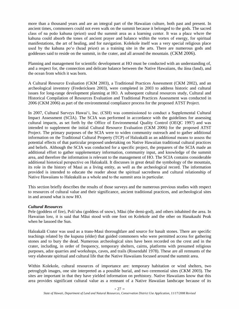
- 27 – State of Hawaii, Department of Land and Natural Resources, Conservation District Use Application, 11/17/2008 Revised
more than a thousand years and are an integral part of the Hawaiian culture, both past and present. In
ancient times, commoners could not even walk on the summit because it belonged to the gods. The sacred
class of na poāo kahuna (priest) used the summit area as a learning center. It was a place where the
kahuna could absorb the tones of ancient prayer and balance within the vortex of energy, for spiritual
manifestations, the art of healing, and for navigation. Kolekole itself was a very special religious place
used by the kahuna po‗o (head priest) as a training site in the arts. There are numerous gods and
goddesses said to reside on the summit, in the crater, and all around the mountain. (CKM 2006).
Planning and management for scientific development at HO must be conducted with an understanding of,
and a respect for, the connection and delicate balance between the Native Hawaiians, the āina (land), and
the ocean from which it was born.
A Cultural Resource Evaluation (CKM 2003), a Traditional Practices Assessment (CKM 2002), and an
archeological inventory (Fredericksen 2003), were completed in 2003 to address historic and cultural
issues for long-range development planning at HO. A subsequent cultural resources study, Cultural and
Historical Compilation of Resources Evaluation and Traditional Practices Assessment was conducted in
2006 (CKM 2006) as part of the environmental compliance process for the proposed ATST Project.
In 2007, Cultural Surveys Hawai‗i, Inc. (CSH) was commissioned to conduct a Supplemental Cultural
Impact Assessment (SCIA). The SCIA was performed in accordance with the guidelines for assessing
cultural impacts, as set forth by the Office of Environmental Quality Control (OEQC 1997) and was
intended to supplement the initial Cultural Resource Evaluation (CKM 2006) for the proposed ATST
Project. The primary purposes of the SCIA were to widen community outreach and to gather additional
information on the Traditional Cultural Property (TCP) of Haleakalā as an additional means to assess the
potential effects of that particular proposed undertaking on Native Hawaiian traditional cultural practices
and beliefs. Although the SCIA was conducted for a specific project, the preparers of the SCIA made an
additional effort to gather supplementary information, community input, and knowledge of the summit
area, and therefore the information is relevant to the management of HO. The SCIA contains considerable
additional historical perspective on Haleakalā. It discusses in great detail the symbology of the mountain,
its role in the history of Maui as a living entity, as well as the archeological record. The information
provided is intended to educate the reader about the spiritual sacredness and cultural relationship of
Native Hawaiians to Haleakalā as a whole and to the summit area in particular.
This section briefly describes the results of those surveys and the numerous previous studies with respect
to resources of cultural value and their significance, ancient traditional practices, and archeological sites
in and around what is now HO.
Cultural Resources
Pele (goddess of fire), Poli‗ahu (goddess of snow), Māui (the demi-god), and others inhabited the area. In
Hawaiian lore, it is said that Māui stood with one foot on Kolekole and the other on Hanakauhi Peak
when he lassoed the Sun.
Haleakalā Crater was used as a trans-Maui thoroughfare and source for basalt stones. There are specific
teachings related by the kupuna (elder) that guided commoners who were permitted access for gathering
stones and to bury the dead. Numerous archeological sites have been recorded on the crest and in the
crater, including, in order of frequency, temporary shelters, cairns, platforms with presumed religious
purposes, adze quarries and workshops, caves, and trails (Rosendahl 1978). These are all remnants of the
very elaborate spiritual and cultural life that the Native Hawaiians focused around the summit area.
Within Kolekole, cultural resources of importance are: temporary habitation or wind shelters, two
petroglyph images, one site interpreted as a possible burial, and two ceremonial sites (CKM 2003). The
sites are important in that they have yielded information on prehistory. Native Hawaiians know that this
area provides significant cultural value as a remnant of a Native Hawaiian landscape because of its
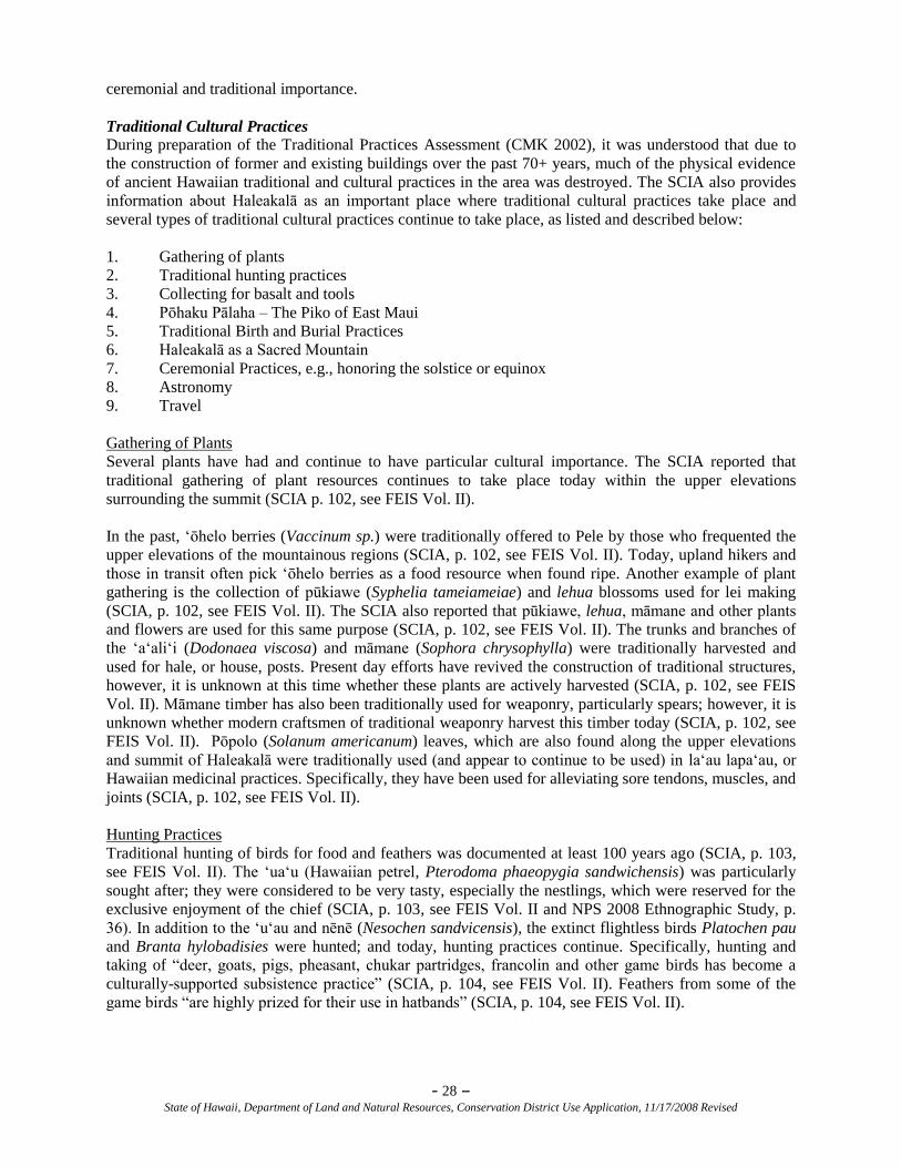
- 28 – State of Hawaii, Department of Land and Natural Resources, Conservation District Use Application, 11/17/2008 Revised
ceremonial and traditional importance.
Traditional Cultural Practices
During preparation of the Traditional Practices Assessment (CMK 2002), it was understood that due to
the construction of former and existing buildings over the past 70+ years, much of the physical evidence
of ancient Hawaiian traditional and cultural practices in the area was destroyed. The SCIA also provides
information about Haleakalā as an important place where traditional cultural practices take place and
several types of traditional cultural practices continue to take place, as listed and described below:
1. Gathering of plants
2. Traditional hunting practices
3. Collecting for basalt and tools
4. Pōhaku Pālaha – The Piko of East Maui
5. Traditional Birth and Burial Practices
6. Haleakalā as a Sacred Mountain
7. Ceremonial Practices, e.g., honoring the solstice or equinox
8. Astronomy
9. Travel
Gathering of Plants
Several plants have had and continue to have particular cultural importance. The SCIA reported that
traditional gathering of plant resources continues to take place today within the upper elevations
surrounding the summit (SCIA p. 102, see FEIS Vol. II).
In the past, ‗ōhelo berries (Vaccinum sp.) were traditionally offered to Pele by those who frequented the
upper elevations of the mountainous regions (SCIA, p. 102, see FEIS Vol. II). Today, upland hikers and
those in transit often pick ‗ōhelo berries as a food resource when found ripe. Another example of plant
gathering is the collection of pūkiawe (Syphelia tameiameiae) and lehua blossoms used for lei making
(SCIA, p. 102, see FEIS Vol. II). The SCIA also reported that pūkiawe, lehua, māmane and other plants
and flowers are used for this same purpose (SCIA, p. 102, see FEIS Vol. II). The trunks and branches of
the ‗a‗ali‗i (Dodonaea viscosa) and māmane (Sophora chrysophylla) were traditionally harvested and
used for hale, or house, posts. Present day efforts have revived the construction of traditional structures,
however, it is unknown at this time whether these plants are actively harvested (SCIA, p. 102, see FEIS
Vol. II). Māmane timber has also been traditionally used for weaponry, particularly spears; however, it is
unknown whether modern craftsmen of traditional weaponry harvest this timber today (SCIA, p. 102, see
FEIS Vol. II). Pōpolo (Solanum americanum) leaves, which are also found along the upper elevations
and summit of Haleakalā were traditionally used (and appear to continue to be used) in la‗au lapa‗au, or
Hawaiian medicinal practices. Specifically, they have been used for alleviating sore tendons, muscles, and
joints (SCIA, p. 102, see FEIS Vol. II).
Hunting Practices
Traditional hunting of birds for food and feathers was documented at least 100 years ago (SCIA, p. 103,
see FEIS Vol. II). The ‗ua‗u (Hawaiian petrel, Pterodoma phaeopygia sandwichensis) was particularly
sought after; they were considered to be very tasty, especially the nestlings, which were reserved for the
exclusive enjoyment of the chief (SCIA, p. 103, see FEIS Vol. II and NPS 2008 Ethnographic Study, p.
36). In addition to the ‗u‗au and nēnē (Nesochen sandvicensis), the extinct flightless birds Platochen pau
and Branta hylobadisies were hunted; and today, hunting practices continue. Specifically, hunting and
taking of ―deer, goats, pigs, pheasant, chukar partridges, francolin and other game birds has become a
culturally-supported subsistence practice‖ (SCIA, p. 104, see FEIS Vol. II). Feathers from some of the
game birds ―are highly prized for their use in hatbands‖ (SCIA, p. 104, see FEIS Vol. II).
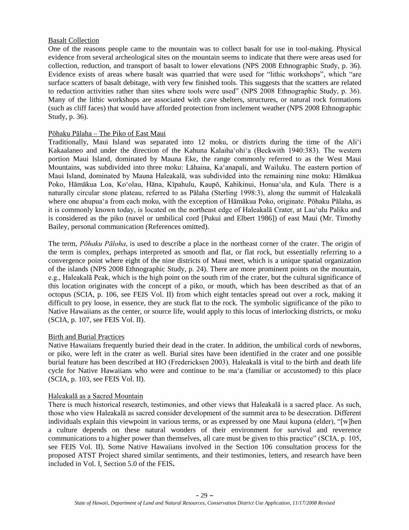
- 29 – State of Hawaii, Department of Land and Natural Resources, Conservation District Use Application, 11/17/2008 Revised
Basalt Collection
One of the reasons people came to the mountain was to collect basalt for use in tool-making. Physical
evidence from several archeological sites on the mountain seems to indicate that there were areas used for
collection, reduction, and transport of basalt to lower elevations (NPS 2008 Ethnographic Study, p. 36).
Evidence exists of areas where basalt was quarried that were used for ―lithic workshops‖, which ―are
surface scatters of basalt debitage, with very few finished tools. This suggests that the scatters are related
to reduction activities rather than sites where tools were used‖ (NPS 2008 Ethnographic Study, p. 36).
Many of the lithic workshops are associated with cave shelters, structures, or natural rock formations
(such as cliff faces) that would have afforded protection from inclement weather (NPS 2008 Ethnographic
Study, p. 36).
Pōhaku Pālaha – The Piko of East Maui
Traditionally, Maui Island was separated into 12 moku, or districts during the time of the Ali‗i
Kakaalaneo and under the direction of the Kahuna Kalaiha‗ohi‗a (Beckwith 1940:383). The western
portion Maui Island, dominated by Mauna Eke, the range commonly referred to as the West Maui
Mountains, was subdivided into three moku: Lāhaina, Ka‗anapali, and Wailuku. The eastern portion of
Maui Island, dominated by Mauna Haleakalā, was subdivided into the remaining nine moku: Hāmākua
Poko, Hāmākua Loa, Ko‗olau, Hāna, Kīpahulu, Kaupō, Kahikinui, Honua‗ula, and Kula. There is a
naturally circular stone plateau, referred to as Pālaha (Sterling 1998:3), along the summit of Haleakalā
where one ahupua‗a from each moku, with the exception of Hāmākua Poko, originate. Pōhaku Pālaha, as
it is commonly known today, is located on the northeast edge of Haleakalā Crater, at Lau‗ulu Paliku and
is considered as the piko (navel or umbilical cord [Pukui and Elbert 1986]) of east Maui (Mr. Timothy
Bailey, personal communication (References omitted).
The term, Pōhaku Pāloha, is used to describe a place in the northeast corner of the crater. The origin of
the term is complex, perhaps interpreted as smooth and flat, or flat rock, but essentially referring to a
convergence point where eight of the nine districts of Maui meet, which is a unique spatial organization
of the islands (NPS 2008 Ethnographic Study, p. 24). There are more prominent points on the mountain,
e.g., Haleakalā Peak, which is the high point on the south rim of the crater, but the cultural significance of
this location originates with the concept of a piko, or mouth, which has been described as that of an
octopus (SCIA, p. 106, see FEIS Vol. II) from which eight tentacles spread out over a rock, making it
difficult to pry loose, in essence, they are stuck flat to the rock. The symbolic significance of the piko to
Native Hawaiians as the center, or source life, would apply to this locus of interlocking districts, or moku
(SCIA, p. 107, see FEIS Vol. II).
Birth and Burial Practices
Native Hawaiians frequently buried their dead in the crater. In addition, the umbilical cords of newborns,
or piko, were left in the crater as well. Burial sites have been identified in the crater and one possible
burial feature has been described at HO (Fredericksen 2003). Haleakalā is vital to the birth and death life
cycle for Native Hawaiians who were and continue to be ma‗a (familiar or accustomed) to this place
(SCIA, p. 103, see FEIS Vol. II).
Haleakalā as a Sacred Mountain
There is much historical research, testimonies, and other views that Haleakalā is a sacred place. As such,
those who view Haleakalā as sacred consider development of the summit area to be desecration. Different
individuals explain this viewpoint in various terms, or as expressed by one Maui kupuna (elder), ―[w]hen
a culture depends on these natural wonders of their environment for survival and reverence
communications to a higher power than themselves, all care must be given to this practice‖ (SCIA, p. 105,
see FEIS Vol. II). Some Native Hawaiians involved in the Section 106 consultation process for the
proposed ATST Project shared similar sentiments, and their testimonies, letters, and research have been
included in Vol. I, Section 5.0 of the FEIS.
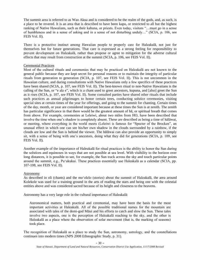
- 30 – State of Hawaii, Department of Land and Natural Resources, Conservation District Use Application, 11/17/2008 Revised
The summit area is referred to as Wao Akua and is considered to be the realm of the gods, and, as such, is
a place to be revered. It is an area that is described to have been kapu, or restricted to all but the highest
ranking of Native Hawaiians, such as their kahuna, or priests. Even today, visitors ―…must go in a sense
of humbleness and in a sense of asking and in a sense of not disturbing unduly…‖ (SCIA, p. 106, see
FEIS Vol. II).
There is a protective instinct among Hawaiian people to properly care for Haleakalā, not just for
themselves but for future generations. That care is expressed as a strong feeling for responsibility to
prevent development on Haleakalā, rather than propose or agree to mitigation for the adverse cultural
effects that may result from construction at the summit (SCIA, p. 106, see FEIS Vol. II).
Ceremonial Practices
Most of the cultural rituals and ceremonies that may be practiced on Haleakalā are not known to the
general public because they are kept secret for personal reasons or to maintain the integrity of particular
rituals from generation to generation (SCIA, p. 107, see FEIS Vol. II). This is not uncommon in the
Hawaiian culture, and during consultations with Native Hawaiians only a few specifics of these practices
have been shared (SCIA, p. 107, see FEIS Vol. II). The best-known ritual to non-Native Hawaiians is the
calling of the Sun, or ―e ala e‖, which is a chant used to greet ancestors, kupuna, and [also] greet the Sun
as it rises (SCIA, p. 107, see FEIS Vol. II). Some consulted parties have shared other rituals that include
such practices as annual pilgrimages to honor certain trees, conducting solstice ceremonies, visiting
special sites at certain times of the year for offerings, and going to the summit for chanting. Certain times
of the day, month, or year are considered important because at these times the Sun is at zenith. The zenith
has particular significance in that there would be the greatest amount of hā, or spiritual breath that comes
from above. For example, ceremonies at Leleiwi, about two miles from HO, have been described that
involve the time when one‘s shadow is completely absent. These are described as being a time of hālāwai,
or meeting, where everything in the world meets (Leleiwi is famous for ―Specter of the Brocken‖, an
unusual effect in which one can see his/her own shadow in the clouds surrounded by a rainbow, if the
clouds are low and the Sun is behind the viewer. The hālāwai can also provide an opportunity to simply
sit, with a sense of being with one‘s ancestors, doing what they did for generations (SCIA, p. 109, see
FEIS Vol. II).
Another example of the importance of Haleakalā for ritual practices is the ability to honor the Sun during
the solstices and equinoxes in ways that are not possible at sea level. With visibility to the horizon over
long distances, it is possible to see, for example, the Sun track across the sky and touch particular points
around the summit, e.g., Pu‗ukukui. These practices essentially use Haleakalā as a calendar (SCIA, pp.
107-108, see FEIS Vol. II).
Astronomy
As described in oli (chants) and the mo‗olelo (stories) about the summit of Haleakalā, the area around
Kolekole was used for a training ground in the arts of reading the stars and being one with the celestial
entities above and was considered sacred because of its height and closeness to the heavens.
Astronomy has a very large role in the cultural importance of Haleakalā:
Astronomical matters, both practical and ceremonial, may have been the basis for the most
important activities at Haleakalā. All of the possible traditional names for the mountain are
associated with tales of the demi-god Māui and his efforts to catch and slow the Sun. These tales
involve two aspects, one is the perception of Haleakalā reaching to the sky, and the other is
Haleakalā as a place where the observation of solar movement (that is, the marking of seasons)
took place.
The recognition of Haleakalā as a place to study the Sun, astronomy, astrology, and the constellations
continues into modern times (NPS 2008 Ethnographic Study, p. 31).
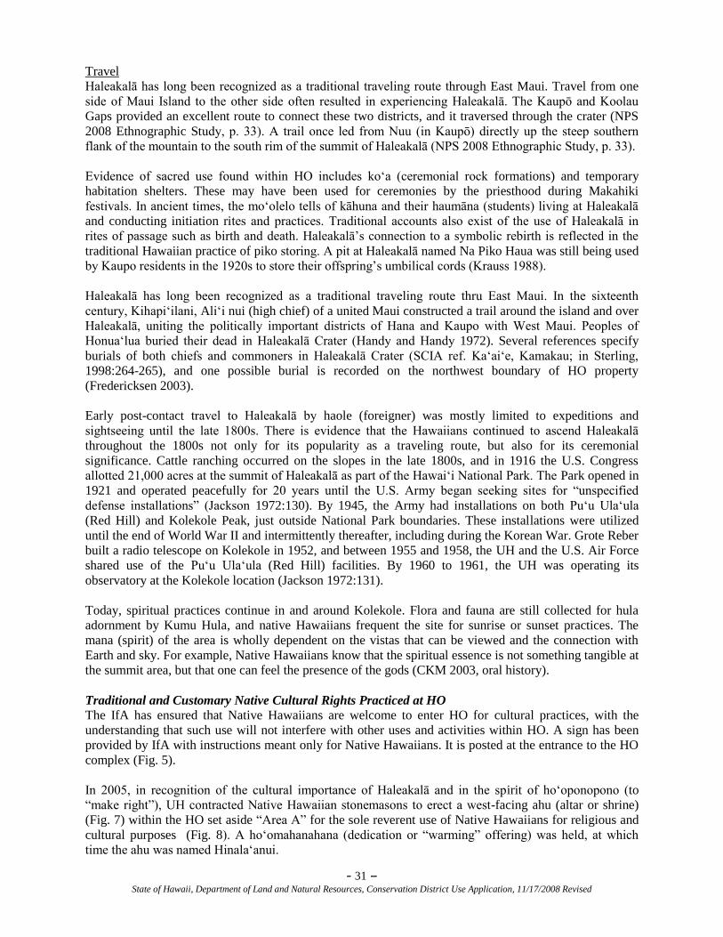
- 31 – State of Hawaii, Department of Land and Natural Resources, Conservation District Use Application, 11/17/2008 Revised
Travel
Haleakalā has long been recognized as a traditional traveling route through East Maui. Travel from one
side of Maui Island to the other side often resulted in experiencing Haleakalā. The Kaupō and Koolau
Gaps provided an excellent route to connect these two districts, and it traversed through the crater (NPS
2008 Ethnographic Study, p. 33). A trail once led from Nuu (in Kaupō) directly up the steep southern
flank of the mountain to the south rim of the summit of Haleakalā (NPS 2008 Ethnographic Study, p. 33).
Evidence of sacred use found within HO includes ko‗a (ceremonial rock formations) and temporary
habitation shelters. These may have been used for ceremonies by the priesthood during Makahiki
festivals. In ancient times, the mo‗olelo tells of kāhuna and their haumāna (students) living at Haleakalā
and conducting initiation rites and practices. Traditional accounts also exist of the use of Haleakalā in
rites of passage such as birth and death. Haleakalā‘s connection to a symbolic rebirth is reflected in the
traditional Hawaiian practice of piko storing. A pit at Haleakalā named Na Piko Haua was still being used
by Kaupo residents in the 1920s to store their offspring‘s umbilical cords (Krauss 1988).
Haleakalā has long been recognized as a traditional traveling route thru East Maui. In the sixteenth
century, Kihapi‗ilani, Ali‗i nui (high chief) of a united Maui constructed a trail around the island and over
Haleakalā, uniting the politically important districts of Hana and Kaupo with West Maui. Peoples of
Honua‗lua buried their dead in Haleakalā Crater (Handy and Handy 1972). Several references specify
burials of both chiefs and commoners in Haleakalā Crater (SCIA ref. Ka‗ai‗e, Kamakau; in Sterling,
1998:264-265), and one possible burial is recorded on the northwest boundary of HO property
(Fredericksen 2003).
Early post-contact travel to Haleakalā by haole (foreigner) was mostly limited to expeditions and
sightseeing until the late 1800s. There is evidence that the Hawaiians continued to ascend Haleakalā
throughout the 1800s not only for its popularity as a traveling route, but also for its ceremonial
significance. Cattle ranching occurred on the slopes in the late 1800s, and in 1916 the U.S. Congress
allotted 21,000 acres at the summit of Haleakalā as part of the Hawai‗i National Park. The Park opened in
1921 and operated peacefully for 20 years until the U.S. Army began seeking sites for ―unspecified
defense installations‖ (Jackson 1972:130). By 1945, the Army had installations on both Pu‗u Ula‗ula
(Red Hill) and Kolekole Peak, just outside National Park boundaries. These installations were utilized
until the end of World War II and intermittently thereafter, including during the Korean War. Grote Reber
built a radio telescope on Kolekole in 1952, and between 1955 and 1958, the UH and the U.S. Air Force
shared use of the Pu‗u Ula‗ula (Red Hill) facilities. By 1960 to 1961, the UH was operating its
observatory at the Kolekole location (Jackson 1972:131).
Today, spiritual practices continue in and around Kolekole. Flora and fauna are still collected for hula
adornment by Kumu Hula, and native Hawaiians frequent the site for sunrise or sunset practices. The
mana (spirit) of the area is wholly dependent on the vistas that can be viewed and the connection with
Earth and sky. For example, Native Hawaiians know that the spiritual essence is not something tangible at
the summit area, but that one can feel the presence of the gods (CKM 2003, oral history).
Traditional and Customary Native Cultural Rights Practiced at HO
The IfA has ensured that Native Hawaiians are welcome to enter HO for cultural practices, with the
understanding that such use will not interfere with other uses and activities within HO. A sign has been
provided by IfA with instructions meant only for Native Hawaiians. It is posted at the entrance to the HO
complex (Fig. 5).
In 2005, in recognition of the cultural importance of Haleakalā and in the spirit of ho‗oponopono (to
―make right‖), UH contracted Native Hawaiian stonemasons to erect a west-facing ahu (altar or shrine)
(Fig. 7) within the HO set aside ―Area A‖ for the sole reverent use of Native Hawaiians for religious and
cultural purposes (Fig. 8). A ho‗omahanahana (dedication or ―warming‖ offering) was held, at which
time the ahu was named Hinala‗anui.
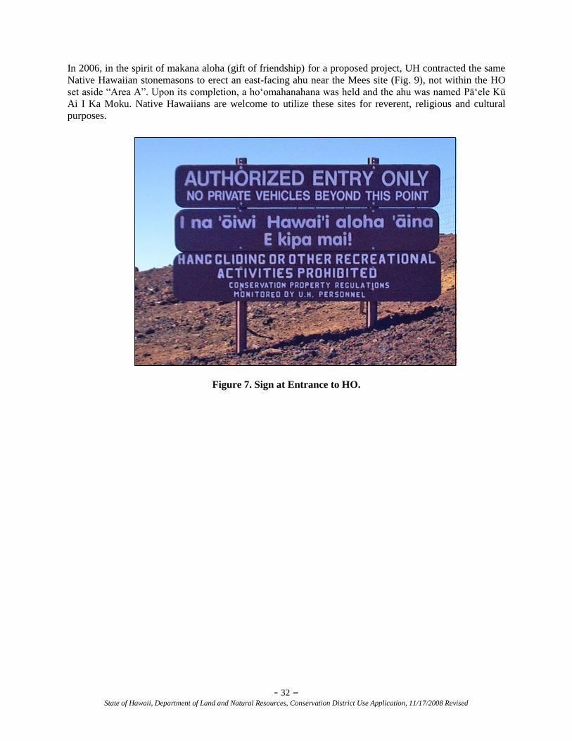
- 32 – State of Hawaii, Department of Land and Natural Resources, Conservation District Use Application, 11/17/2008 Revised
In 2006, in the spirit of makana aloha (gift of friendship) for a proposed project, UH contracted the same
Native Hawaiian stonemasons to erect an east-facing ahu near the Mees site (Fig. 9), not within the HO
set aside ―Area A‖. Upon its completion, a ho‗omahanahana was held and the ahu was named Pā‗ele Kū
Ai I Ka Moku. Native Hawaiians are welcome to utilize these sites for reverent, religious and cultural
purposes.
Figure 7. Sign at Entrance to HO.
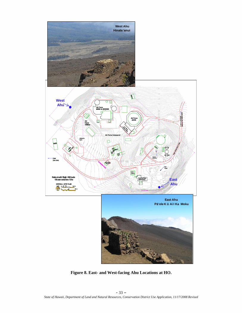
- 33 – State of Hawaii, Department of Land and Natural Resources, Conservation District Use Application, 11/17/2008 Revised
East
Ahu
West
Ahu
East Ahu
Pā‘ele K ū Ai I Ka Moku
East Ahu
Pā‘ele K ū Ai I Ka Moku
West Ahu
Hinala‘anui
West Ahu
Hinala ‘anui
Figure 8. East- and West-facing Ahu Locations at HO.
- 34 – State of Hawaii, Department of Land and Natural Resources, Conservation District Use Application, 11/17/2008 Revised
Figure 9. Set aside “Area A” Location at HO.
Haleakalā Summit
The summit of Haleakalā is considered a significant cultural resource in and of itself. It is eligible for
listing on the National Register of Historic Places (NRHP) as a TCP through consultation with the State
Historic Preservation Division (SHPD) under Criterion ―A‖ for its association with the cultural landscape
of Maui and this is reflected in the number of known uses, oral history, mele and legends surrounding
Haleakalā. The term ―Traditional Cultural Property‖ is used in the NRHP to identify a property ―that is
eligible for inclusion in the NRHP because of its association with cultural practices or beliefs of a living
community that, (a) are rooted in that community‘s history, and (b) are important in maintaining the
continuing cultural identity of the community‖ (DOI 1994). The summit is also eligible under NRHP
Criterion ―C‖ because it is an example of a resource type, a natural summit, and a source for both
traditional materials and sacred uses. The value ascribed to Haleakalā as a TCP can be expressed in five
distinct attributes, solidifying the role of the summit as a place of value.
1. Haleakalā summit is considered by Native Hawaiians, as well as more recent arrivals to Hawai‗i,
as a place exhibiting spiritual power.
2. The summit of Haleakalā is significant as a traditional cultural place because of traditional
cultural practices conducted there. For both Hawaiians and non-Hawaiians who live and visit
here, the summit is a place of reflection and rejuvenation.
3. The mo‗olelo and oli surrounding the summit present a collection of stories suggesting the
significance of Haleakalā as a TCP.
4. Some believe that the summit possesses therapeutic qualities.
5. The summit provides an ―experience of place‖ that is remarkable.
- 35 – State of Hawaii, Department of Land and Natural Resources, Conservation District Use Application, 11/17/2008 Revised
Historic Resources
One historic site is present at HO. It is identified as the Reber Circle site, which is a remnant of early
1950‘s astronomy construction that lies at the peak of Pu‗u Kolekole. It is designated by the State
Inventory of Historic Places (SIHP) as Site 5443 (UH IfA 2005) and is eligible for listing on the NRHP
under Criterion ―A‖ because of its association with mid-20th century scientific studies at Haleakalā, and
under Criterion ―D‖ for its information content. This site remnant consists of a concrete and rock
foundation that was part of the former radio telescope facility that was constructed in 1952 by Grote
Reber, an early pioneer of radio astronomy. The bulk of this structure was dismantled about 18 months
after the facility was completed. This site is composed of a concrete and rock foundation that is
approximately 25 meters (82 feet) in diameter, the outer rim of which is up to 1 meter (3.28 feet) in width
and approximately 80 centimeters (2.62 feet) in height.
Archeological Resources
There were two archeological surveys conducted in portions of HO during the 1990s. The first of these
was in 1990 and consisted of a reconnaissance survey by Pacific Northwest Laboratory on behalf of the
US Air Force for the Advanced Electro-optical System Environmental Assessment (AEOS) (Chatters
1991). Cultural Surveys Hawai‗i, Inc., conducted the second study, an archeological inventory, in 1998.
During the course of this study, a walkover, four archeological sites were identified, primarily along the
western side of Kolekole. These sites included 23 temporary shelters and a short low wall. These wind
shelters were typically constructed against the existing rock outcrop of the hill. The sites were designated
Site 50-50-11-2805 through 50-50-11-2808. One sling stone was found on the floor of Feature J at Site
50-50-11-2807. In addition, one ‗opihi (limpet) (Cellana spp.) shell, was noted on the surface of the
Feature B floor of Site 50-50-11-2808. There was no subsurface investigation carried out, and only Site
50-50-11-2805 was mapped (additional inventory work was done at these sites in 2005).
Cultural Surveys Hawai‗i, Inc. conducted another study in 2000 (FTF EA), in conjunction with the
planned construction of the FTF. They located two previously unidentified sites (50-50-11-4835 and 50-
50-11-4836) to the west of the MSO facility. Both of these sites were constructed against an exposed rock
outcrop. Site 50-50-11-4835 consists of two features—both historic rock enclosures filled with burned
remnants of modern refuse—obviously historic trash burning pits. The researchers speculated that the
U.S. Army might have initially used these during the war and later UH workers used them (FTF EA). Site
50-50-11-4836 consists of three terraces, a rock enclosure, two leveled areas and a rock wall, all
constructed against an exposed rock outcrop. Five of the features are interpreted as temporary shelters,
while the two leveled areas were of indeterminate usage. Although one test unit did not reveal any pre-
Contact cultural materials, their construction is consistent with pre-Contact structures used for temporary
shelters in other areas of Haleakalā Crater (Bushnell and Hammatt). The IfA has preserved both sites.
A comprehensive archeological inventory survey of HO was completed in fall 2002 (UH IfA 2005) and
the inventory survey report was approved by SHPD. An archeological preservation plan for ―Science
City‖ (Xamanek Researches, 2006) was prepared in 2006 and approved by SHPD in a July 10, 2006,
review letter (DLNR 2006). Whereas surveys had previously been conducted for specific construction
projects within HO and a number of archeological features had been identified, the 2002 survey of the
entire 18.166 acres for the LRDP (UH IfA 2005) was exhaustive and included location and description of
six previously unidentified sites. These sites were assigned State of Hawai‗i designations, and further
documentation was obtained for four previously identified sites that were listed with the SHPD. In total,
29 new features were identified and five excavation units were used to sample selected features that were
located in some of the previously undocumented sites. These sites consist of wind shelters, two
petroglyph images, a possible burial feature, and an historic foundation known as Reber Circle.
Supplemental information was obtained from Sites 50-50-11-2805 to 50-50-11-2808 per discussions with
Dr. Melissa Kirkendall of the SHPD Maui office. In addition, a trail segment was recorded at Site 50-50-
11-4836 and designated as Feature F. Several isolated pieces of coral were noted in the southeastern
portion of the 18.166-acre study area, but not assigned a formal site number because the coral pieces were
not weathered. A possible site consisting of several pieces of coral in a boulder was plotted on the project
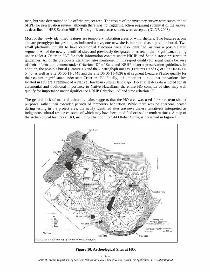
- 36 – State of Hawaii, Department of Land and Natural Resources, Conservation District Use Application, 11/17/2008 Revised
map, but was determined to lie off the project area. The results of the inventory survey were submitted to
SHPD for preservation review, although there was no triggering action requiring submittal of the survey,
as described in HRS Section §6E-8. The significance assessments were accepted (DLNR 2003).
Most of the newly identified features are temporary habitation areas or wind shelters. Two features at one
site are petroglyph images and, as indicated above, one new site is interpreted as a possible burial. Two
small platforms thought to have ceremonial functions were also identified, as was a possible trail
segment. All of the newly identified sites and previously designated ones retain their significance rating
under at least Criterion ―D‖ for their information content under NRHP and State historic preservation
guidelines. All of the previously identified sites mentioned in this report qualify for significance because
of their information content under Criterion ―D‖ of State and NRHP historic preservation guidelines. In
addition, the possible burial (Feature D) and the 2 petroglyph images (Features F and G) of Site 50-50-11-
5440, as well as Site 50-50-11-5441 and the Site 50-50-11-4836 trail segment (Feature F) also qualify for
their cultural significance under state Criterion ―E‖. Finally, it is important to note that the various sites
located in HO are a remnant of a Native Hawaiian cultural landscape. Because Haleakalā is noted for its
ceremonial and traditional importance to Native Hawaiians, the entire HO complex of sites may well
qualify for importance under significance NRHP Criterion ―A‖ and state criterion ―E‖.
The general lack of material culture remains suggests that the HO area was used for short-term shelter
purposes, rather than extended periods of temporary habitation. While there was no charcoal located
during testing in the project area, the newly identified sites are nevertheless tentatively interpreted as
indigenous cultural resources, some of which may have been modified or used in modern times. A map of
the archeological features at HO, including Historic Site 5443 Reber Circle, is presented in Figure 10.
Data based on 2003 survey by Xamanek Researches, Inc.
Figure 10. Archeological Sites at HO.
- 37 – State of Hawaii, Department of Land and Natural Resources, Conservation District Use Application, 11/17/2008 Revised
5.2 Identify the extent to which those resources, including traditional and customary native
Hawaiian rights, will be affected or impaired by the proposed action.
During construction and operation of ATST, the presence of an additional large, white observatory
structure at HO would be considered intrusive on Native Hawaiian cultural practices in the summit area.
Also, during construction, noise levels would exceed those currently existing at HO. For those whose
traditional and customary Native Hawaiian rights require only the natural soundscape those rights could
be affected during periods when construction noise exceeds the ambient noise levels.
5.3 What feasible action, if any, could be taken by the Board of Land and Natural Resources
regarding your application to reasonably protect native Hawaiian rights?
IfA requests that the SHPD division of DLNR support and participate in the measures developed to
protect Native Hawaiian rights agreed to by signatories of the Programmatic Agreement (PA) in
Appendix E regarding the ATST and the IfA MP for HO, as follows:
Programmatic Agreement
For the PA, NSF invited public participation pursuant to the NHPA Section 106 process to identify and
address issues concerning Native Hawaiian organizations (NHO) and individuals who may attach
religious and cultural significance to a historic property that may be affected by the proposed
construction. Consultation began in June 2005 with formal notification letters to the Advisory Council on
Historic Preservation (ACHP), the SHPD, and Maui Native Hawaiian individuals. Over the years, a list of
interested and potentially interested parties was generated from lists provided by the Office of Hawaiian
Affairs (OHA), the U.S. Department of the Interior‘s Office of Hawaiian Relations website (DOI 2007),
through ongoing requests from NSF to the public during Section 106 consultation meetings and
information letters about the Section 106 process, and through community interest and participation
during consultation meetings. The process culminated in a PA to stipulate measures to be undertaken, a
number of which are specifically to protect Native Hawaiian rights, i.e., retention of a cultural specialist,
required ―Sense of Place training‖, etc.
Management Plan
With respect to the protection of Native Hawaiian rights in the IfA MP, the IfA has ensured that Native
Hawaiians are welcome to enter HO for cultural practices. A sign provided by IfA has been posted at the
entrance to HO with instructions meant only for Native Hawaiians. In addition, Native Hawaiian dry
stack masons erected two ahu on HO property to delineate ceremonial sites. In addition, the IfA set aside
approximately 0.55 acres of HO property around the west-facing ahu for the sole reverent use of Native
Hawaiians for religious and cultural purposes, with the understanding that such use will not interfere with
other uses and activities within HO (Fig. 6).
5.4 Does the proposed land use have an effect (positive/negative) on public access to and along
the shoreline or along any public trail?
Shoreline Access
The site is located at 9,980 feet above sea level and, therefore, will have no effect on public access to and
along the shoreline pursuant to the County of Maui Planning Department map entitled Island of Maui
Showing Special Management Area. This map is provided by the County of Maui GIS Program, Office of
the Managing Director, dated July 2002, and is located in the Zoning and Administration Enforcement
Division of the Planning Department, Wailuku, Maui. The map clearly indicates that the proposed ATST
facility is not located within a shoreline access area.
Public Trails
There are no public trails within the HO boundaries. The entire HO complex is off limits to the general
public as shown on the sign in Figure 5.
- 38 – State of Hawaii, Department of Land and Natural Resources, Conservation District Use Application, 11/17/2008 Revised
5.5 Does the proposed use have an effect (positive/negative) on beach processes?
The site is located at 9,980 feet above sea level and will have no effect on beach processes as indicated in
Section 5.4 above.
5.6 Will the proposed use cause increased runoff or sedimentation?
A National Pollutant Discharge Elimination System (NPDES) Permit is required for this project. An
application for a permit will be submitted upon issuance of a CDUP.
There are no water bodies at HO. The Polipoli Springs water system is within the project aquifer system.
The Polipoli Spring State Recreation Area water system is in the Kahikinui Forest Reserve, 9.7 miles
upland from Kula on Waipoli Road. The water system is owned and operated by the State of Hawai‗i and
managed by the Hawai‗i DLNR State Parks. The water system serves a park cabin and campground area.
The non-potable source for the water system is an unnamed spring whose water flows through a 1.5-inch
pipe to the campground area. The estimated water demand is 2,000 gallons daily (Fukunaga and
Associates 2003).
Drainage Features
On the native slopes of Haleakalā, virtually all precipitation infiltrates the soil profile. Once in the soil,
gravity continues to force the water down into the soil. When the water hits a less permeable layer, such
as basalt, it flows in the path of least resistance. This means subsurface water flows, driven by gravity,
down gradient along the surface of the basalt layer. The flow continues along the interface between the
highly pervious cinder material and the basalt layer until it either resurfaces as a spring or stream or flows
into a fissure in basalt, contributing to groundwater storage (UH IfA 2005a).
In March 2005, soil borings were taken at HO to support design planning for construction of the Proposed
Action (see FEIS Vol. II, Appendix K-Soils Investigation Report). The results of the exploratory borings
revealed that the soil profile generally consists of sands and gravels on top of a basalt layer. This means
water can easily infiltrate the upper soils and then becoming significantly slowed when it reaches the
basalt layer, which ranges from 5 to 21 feet (UH IfA 2005a).
All precipitation falling near the summit is infiltrated and flows subsurface toward the natural drainage
courses, such as Manawainui Gulch. Loss of rainfall would be caused by evaporation in the soil column
(UH IfA 2005a). Due to site topography, as well as a small collection of stormwater conveyance systems
consisting of concrete channels and culverts, runoff generated within HO is controlled and conveyed via
natural drainage paths to an infiltration basin at the western extremity of HO property. This infiltration
basin is a depression that represents an old vent on the cinder cone, and its substrate is considerably more
porous than the lava or spatter portions of Kolekole. The runoff collection system was originally designed
to maintain stormwater runoff on paved surfaces and consists of gutters and channels intended to prevent
stormwater from discharging onto native soils adjacent to paved surfaces. Ten main stormwater flow
paths have been identified at HO. In the FEIS Vol. I, Section 3.0, Figure 3-10 illustrates the existing
runoff patterns associated with HO and provides a brief description of each flow path in the HO drainage
system.
5.7 Will the proposed use cause any visual impact on any individual or community?
An exhaustive analysis of the visual impacts to visual resources and view planes of the proposed ATST
Project is found in the FEIS Vol. I, Sections 4.5 and 4.17.8. The proposed use will cause a substantial
visual impact on visitors to the summit area of HALE and only negligible impacts on populated parts of
the greater Maui community. The viewing areas used to assess and describe visual effects from the
proposed ATST Project are:
- 39 – State of Hawaii, Department of Land and Natural Resources, Conservation District Use Application, 11/17/2008 Revised
1. Pu‗u Ula‗ula (Red Hill) Overlook,
2. The areas of HALE adjacent to HO, but not on Pu‗u Ula‗ula (Red Hill), including Magnetic Peak,
3. The upper Park roadway, including the Haleakalā Visitor Center,
4. The crater,
5. The lower Park roadway, including Hosmer Grove; and,
6. Populated areas of Maui, including windward, Upcountry, Central Valley, and South Maui
locations.
From Section 4.5 of the attached FEIS, the impact on visual resources at the Pu‗u Ula‗ula (Red Hill)
Overlook from the construction and operation of the proposed ATST Project is substantial because of its
prominence in relatively close-up views. The location relative to other HO structures would result in the
appearance of an increase in the total horizontal space occupied by the HO footprint (see FEIS Vol. I,
Section 4.5, Fig. 4-4b). Though it would appear taller than any other structure in the view, it would not
appear out of scale or character compared with the existing view toward HO from the overlook.
From areas in HALE adjacent to HO, the proposed ATST Project would appear in views to increase the
total amount of horizontal space occupied by HO. The proposed ATST Project would also appear as the
tallest man-made structure in views where HO is visible, through it would be subordinate to Magnetic
Peak in terms of visual dominance (see FEIS Vol. I, Section 4.5, Fig. 4-8b). The visual character of views
toward HO in adjacent areas in HALE remains defined by topography and the general downward slope to
the west from Magnetic Peak. The proposed ATST Project would constitute a substantial (major) impact.
From within the upper two miles of the Park roadway, the proposed ATST Project would occupy varying
portions of the existing landscape. In closer views, the new structure would occupy greater space than in
views from further away (see FEIS Vol. I, Section 4.5, Figs. 4-10b and 4-11b); however, the proposed
ATST Project would appear in all such views to increase the horizontal footprint of HO. As with other
views, however, the new structure would appear consistent with the existing visual character of its
immediate surroundings at HO. The visual effect of adding the ATST structure would be to intensify the
appearance of the developed area in closer views. In views from further away in the area, such visual
effects would not be as noticeable. As such the proposed ATST Project would result in impacts on visual
resources, but those would be less than substantial.
The proposed ATST Project would be intermittently visible in views from the lower Park roadway,
including the area from the entry station to just above the Park Headquarters Visitor Center (see FEIS
Vol. I, Section 4.5, Fig. 4-12b). In these views, the proposed ATST Project would be barely discernable
alongside other existing structures at HO and the footprint of the area would appear to increase slightly.
The new structure would not substantially affect the visual quality of such views. The impact to visual
resources in this area would be negligible.
From inside the crater, the upper part of the 250-foot crane that would be used during construction of the
proposed ATST Project would be visible from trails and camping areas within the crater, during such
times when the crane is extended. No other past or present actions at HO are visible within the crater and
the crane would not be distinguishable as other than a faint, short segment above the rim. Where visible, it
would appear small relative to the 3,000-foot crater walls. To the extent that it could be visible, however,
such an object would potentially affect the visual quality of views from within the crater, which consists
of mainly undeveloped backcountry. The impact to visual resources resulting from construction activities
would be minor.
Where visible in more distant views from populated areas of Maui, the proposed ATST Project would
appear as part of the cluster of structures at HO along the ridgeline (see FEIS Vol. I, Section 4.5, Figs. 4-
15 through 4-27). While a slight increase in the amount of overall space occupied by HO along the
ridgeline would be visible from some locations, from others, the new structure would not be
distinguishable from other existing structures. The new building would not appear to substantially
- 40 – State of Hawaii, Department of Land and Natural Resources, Conservation District Use Application, 11/17/2008 Revised
increase the size of the developed ridgeline, nor would it substantially alter the existing visual quality of
views toward the proposed ATST Project site. The anticipated visual effects from the proposed ATST
Project would not contribute to any further loss of visual resources. Therefore, in views from the
populated areas of Maui, the proposed ATST Project would result in negligible impacts to visual
resources.
6.0 EXISTING SITE INFORMATION
To better understand existing features on and of the land, mapping of existing features is requested.
Mapping of existing features may be combined. Please include Titles, Legends and North arrows.
6.1 Are there existing structures on the parcel? Yes X No
If yes, please describe below and include/illustrate on a map entitled existing structures.
6.2 Will any existing structures be demolished or removed? ___Yes X No
If yes, describe how below. Please indicate/illustrate demolished structure on a map entitled
structures to be demolished/removed.
6.3 Has the parcel been graded or landscaped? ___Yes X No
If yes, describe below. Please describe cubic yards affected and/or area of landscaping on a
map entitled areas previously graded or landscaped.
6.4 Describe existing utilities. Include electricity, water, telephone, drainage, and sewerage.
Please illustrate on a map entitled existing utilities.
At the proposed ATST Project site east of the Mees facility, there are currently no existing utilities;
however, the following is a description of existing utilities within HO.
Wastewater and Solid Waste Disposal
Septic tanks are the primary means of sewage disposal within the summit area. There is no central
waste/sewage collection or storage system at the Haleakalā summit. Each user provides for the collection
and proper storage of wastewater and sewage generated by that site.
Trash collection is the responsibility of building maintenance personnel for each facility located within
the HO complex. Non-hazardous trash is disposed of off-site in a licensed landfill, with computer paper
and aluminum being recycled. Hazardous wastes and petroleum product wastes are segregated at the
generation point and handled separately.
Stormwater and Drainage System
On the slopes of Haleakalā, as mentioned in the FEIS Vol. I, Section 3.7-Water Resources, virtually all
precipitation infiltrates the soil profile. Once in the soil, gravity continues to force the water down into the
soil. When the water hits a less permeable layer, such as basalt, it will flow in the path of least resistance.
At HO, this confining layer of basalt ranges from depths of 5 to 20+ feet. The significance of a confining
layer of basalt near the summit area is that all precipitation falling near the summit is infiltrated and flows
subsurface toward the natural drainage courses such as Manawainui Gulch. As a result, runoff from the
impervious surfaces associated with HO facilities and adjacent roads may not increase the total volume of
stormwater flow entering natural drainages, but may only affect the way it is transported there (UH IfA
2005b). (Hydrologic conditions of stormwater drainage within HO is further discussed in the FEIS Vol. I,
Section 3.7–Water Resources.)
Electrical Systems
MECO generates electricity for HO. There is a 3750/4688 kilovolt-ampere (kVA) transformer at the Kula
substation that presently serves HO. The site is connected via 23 kV conductors on power lines to a 450
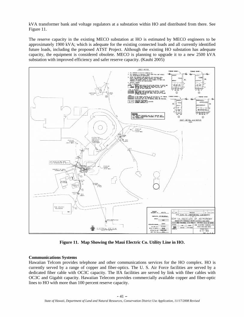
- 41 – State of Hawaii, Department of Land and Natural Resources, Conservation District Use Application, 11/17/2008 Revised
kVA transformer bank and voltage regulators at a substation within HO and distributed from there. See
Figure 11.
The reserve capacity in the existing MECO substation at HO is estimated by MECO engineers to be
approximately 1900 kVA; which is adequate for the existing connected loads and all currently identified
future loads, including the proposed ATST Project. Although the existing HO substation has adequate
capacity, the equipment is considered obsolete. MECO is planning to upgrade it to a new 2500 kVA
substation with improved efficiency and safer reserve capacity. (Kauhi 2005)
Figure 11. Map Showing the Maui Electric Co. Utility Line in HO.
Communications Systems
Hawaiian Telcom provides telephone and other communications services for the HO complex. HO is
currently served by a range of copper and fiber-optics. The U. S. Air Force facilities are served by a
dedicated fiber cable with OC3C capacity. The IfA facilities are served by link with fiber cables with
OC3C and Gigabit capacity. Hawaiian Telecom provides commercially available copper and fiber-optic
lines to HO with more than 100 percent reserve capacity.
- 42 – State of Hawaii, Department of Land and Natural Resources, Conservation District Use Application, 11/17/2008 Revised
The Federal Aviation Administration (FAA) operates and maintains 50-watt transmitter and receiving
equipment for remote air/ground interisland and trans-Pacific communications to and from aircraft. The
antennas for these transmitters/receivers are located on two towers within the FAA property adjacent to
HO. The frequencies for transmission and receiving are in the Very High Frequency (VHF) and Ultra-
High Frequency (UHF) radio bands, to and from transiting aircraft at altitudes from 8,000 to 50,000 feet.
6.5 Describe existing access. Illustrate and include roadways and public trails on a map entitled
existing access. Give major street names if available.
Existing access into and out of HO is exclusively via HALE (Fig. 12) and then through the entrance to the
HO complex just past Pu‗u ‗Ula ‗Ula (Red Hill). There is no general public access to HO and authorized
entry only is posted on the sign (Fig. 5) located at the entrance to the facilities. Native Hawaiians are
welcome to enter for cultural and traditional practices, as indicated on the sign.
There are two other access roads that serve the Haleakalā summit area. The FAA maintains a non-
exclusive access road to facilities in the Saddle Area and the FAA Low Site. There is also an unimproved
access road known as Skyline Drive (Fig. 12), which originates 0.5 miles away from HO at the Saddle
Area. It traverses the Southwest Rift Zone, ultimately leading to Spring State Recreation Area (also
known as Polipoli State Park), which is located at 6,200 feet above sea level (ASL) within the fog belt of
the Kula Forest Reserve (DLNR, Hawai‗i State Parks). Its entire length is located on State land within the
Forest Reserve. A locked gate near the Saddle Area restricts vehicle access to the road from the Haleakalā
summit to only those holding DLNR permits. Hikers and hunters use the unpaved road. There are sections
of this trail that have a steep grade and soft cinder roadbed that will not support standard construction
truck traffic, only smaller vehicles with four-wheel drive.
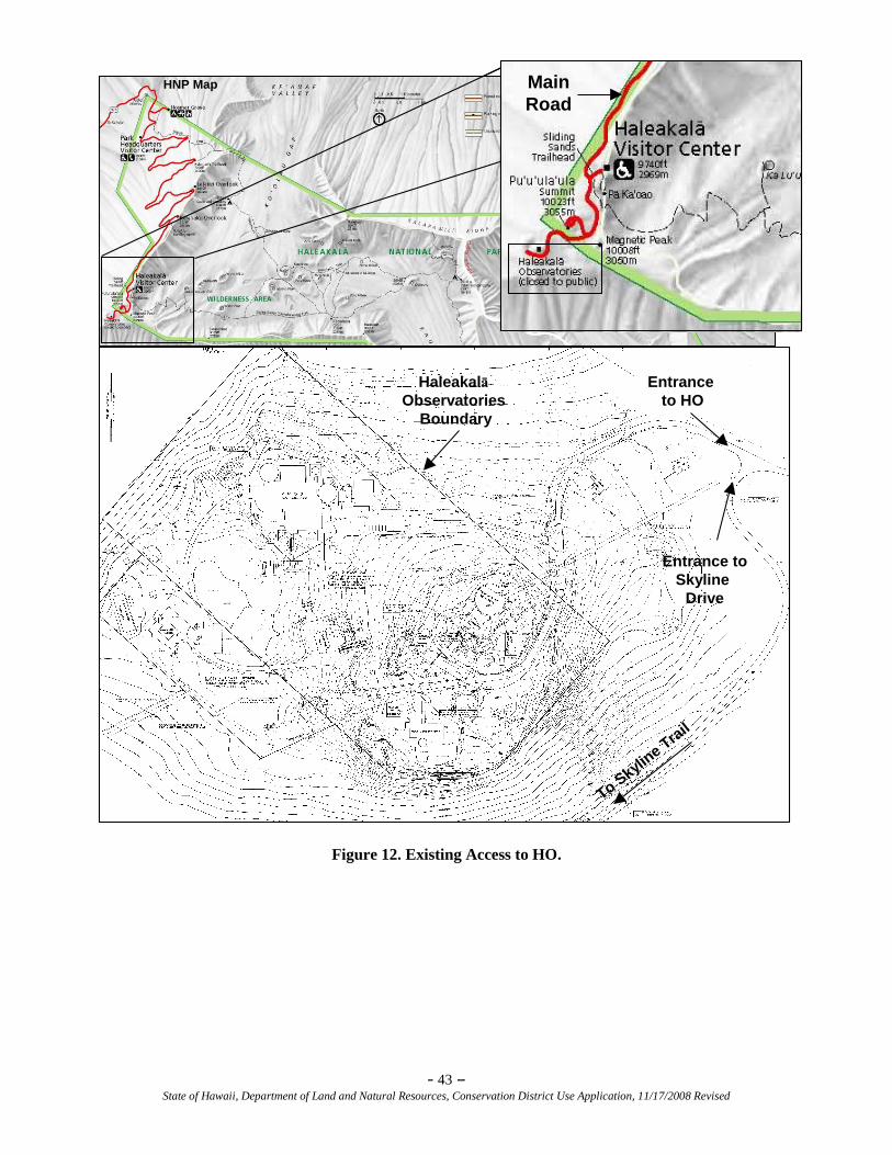
- 43 – State of Hawaii, Department of Land and Natural Resources, Conservation District Use Application, 11/17/2008 Revised
Figure 12. Existing Access to HO.
Haleakalā
Observatories
Boundary
Entrance
to HO
Entrance to
Skyline
Drive
To Skyl
ine T
rail
HNP Map Main
Road
Haleakalā
Observatories
Boundary
Entrance
to HO
Entrance to
Skyline
Drive
To Skyl
ine T
rail
HNP Map Main
Road
Main
Road
- 44 – State of Hawaii, Department of Land and Natural Resources, Conservation District Use Application, 11/17/2008 Revised
6.6 Describe Flora and Fauna. Illustrate general location and types of flora and fauna on a
map entitled resources. Indicate if rare or endangered native plants and/or animals are
present.
Detailed botanical and avifaunal survey information and management plans can be found in the FEIS Vol.
I, Section 3.3-Biological Resources and Vol. II, Appendices C(1), C(2), C(3) and E, and in the LRDP.
BOTANICAL RESOURCES
The landscape at HO is considered to be an Argyroxiphium/Dubautia alpine dry shrubland vegetation
type. Dry alpine shrublands are typically open communities, occurring between about the 9,800 to
11,100-foot elevations in Hawai‗i, predominantly on barren cinders, with very sparse vegetation cover
(UH IfA 2005a). The substrate is a mixture of ash, cinders, pumice, and lava (UH IfA 2005a). Vegetation
is sparse, varying from a near barren landscape (<1 percent cover) to about 10 percent cover. Vegetation
is low to the ground, no more than 3 feet (1 meter) tall anywhere on the site. During the November 2002,
LRDP survey conducted by Starr Environmental (UH IfA 2005a), a total of 32 plant species were
observed, consisting of 11 (34 percent) native species and 21 (66 percent) non-native species. The
December 2005 survey identified 25 plant species, consisting of 11 native species and 14 non-native
species (see FEIS, Vol. II, Appendix E-Botanical Survey).
A more recent survey was conducted in June 2009 (see FEIS, Vol. II, Appendix E-Botanical Survey). It
indicated that, in general, the number of species has increased over time and it appears the distribution
and abundance of both native and non-native plants has increased. Global Positioning System (GPS)
work conducted during this latest study will allow for greater resolution detail of future vegetation
changes.
At HO, the total number of plant species has increased from a total of 32 plant species (11 were native
and 21 were non-native) in 2002, to a total of 44 plant species (3 new natives and 9 new non-natives, for a
total of 14 native species and 30 non-native species) in 2009. Species previously reported from HO that
were not observed in 2009 include Anthoxanthum odoratum and Senecio sylvaticus. These species may
have disappeared, may have been overlooked, or may persist as seed in the soil. The 9 new non-native
species recorded in 2009 included Ageratina adenophora, Bromus diandrus, Conyza bonariensis,
Dactylis glomerata, Festuca rubra, Pennisetum clandestinum, Trifolium repens, Unknown sp., and Vulpia
myuros. These species may be new arrivals, they may have been overlooked in previous studies, or
perhaps they were persisting as seeds in the soil and have recently germinated. The 3 new native species
recorded in 2009 included Dryopteris wallichiana, Pteridium aquilinum var. decompositum, Silene
struthioloides. These could be new arrivals, but these inconspicuous natives could have just as easily
been overlooked in previous surveys.
The land in HO can be divided into two general areas: undisturbed and disturbed (i.e. those where
construction or other human influence has occurred). Undisturbed areas are comprised of predominantly
native plants including shrubs, herbs, and grasses. Three species of native ferns are found in rock crevices
and overhangs around the Pan-STARRS (PS-1) observatory and on the steep slopes on the southeast
portion of the property near the MSO facility.
Areas of HO property where construction has occurred generally support fewer native species and contain
more weeds. One notable exception is the endemic ‗ahinahina, or Haleakalā silversword, which is found
exclusively on areas where construction has occurred. The only tree species found at HO were two
unidentified pines (Pinus sp.) located between a weather station tower and the MSO facility, which were
approximately 20 cm (7.87 inches) tall and looked more like a small multi-branched shrub than a tree.
This was the first record of pines on the summit of Haleakalā. It was not known if the trees were planted,
arrived as contaminants in soil, or arrived through natural wind dispersal. These trees were thought to be
many years old despite their minimal height (compared to other pine species). At the recommendation of
the Friends of Haleakalā National Park, these trees were removed.
- 45 – State of Hawaii, Department of Land and Natural Resources, Conservation District Use Application, 11/17/2008 Revised
There are ten native species and nine non-native plants species found on the Mees site. Portions of the site
which were moderately disturbed, especially areas near buildings and roads, contain the most weeds (non-
native species) and fewest native species. Non-native plants found on the Mees site include thyme-leaved
sandwort (Arenaria serpyllifolia), storksbill, hairy cat‘s ear, black medick (Medicago lupulina), evening
primrose (Oenothera stricta subsp. stricta), pine (Pinus sp.), English plantain (Plantago lanceolata),
Kentucky bluegrass (Poa pratensis), and common or spring vetch (Vicia sativa subsp. nigra). (see FEIS
Vol. II, Appendix E-Botanical Survey).
Portions of the site that were the least disturbed contain the most native plant species and the least weeds.
Native plants found on the Mees site include Hawaiian bentgrass, ‗iwa ‗iwa, ‗oali‗i, hairgrass
(Deschampsia nubigena), kupaoa, kalamoho (Pellaea ternifolia), pukiawe (Styphelia tameiameiae),
tetramolopium (Tetramolopium humile), mountain pili (Trisetum glomeratum), and ohelo. (see FEIS Vol.
II, Appendix E-Botanical Survey).
The most undisturbed areas of HO hold remnant pockets of native plants indicative of relatively pristine
conditions. Two native shrubs, ohelo and pukiawe, appear to be sensitive to disturbance/urbanization on
Pu‗u Kolekole, and were found on the proposed construction site adjacent to the MSO facility.
Alien Invasive Species
The introduction of alien invasive species (AIS) was evaluated based upon what is known about existing
and past loss of habitat at HO. According to the botanical survey of HO conducted in 2005, there were
more non-native plants relative to similar adjacent ―pristine‖ areas, such as HALE, the Kahikinui Forest
Reserve, and the Kula Forest Reserve. The report cited a number of reasons for this. To some extent,
development seems to promote plant growth, both native and non-native. This is likely due to disturbance
to the soil from construction, additional water sources from discharge pipes and gutters, and protection
from the elements by objects such as building foundations and sidewalks. As a result, both native and
non-native plants are able to find refuge in otherwise inhospitable locations. Endangered, Threatened, Listed, or Proposed Plant Species
For detailed information, see FEIS Vol. I, Section 3.3.3.1- Endangered, Threatened, Listed or Proposed
Avifaunal Species.
The ‗ahinahina or Haleakalā silversword are Federally-listed as a ―threatened‖ species, meaning they may
become endangered throughout all or a significant portion of their range if no protective measures are
taken. No ‗ahinahina were located on or around the proposed ATST Project area.
FAUNAL RESOURCES
Fauna at HO consist of avifaunal species, mammals, and invertebrates. Three Federal- and State-listed
animal species, described below, occur in the summit area and slopes of Haleakalā. For detailed
information, see FEIS Vol. I, Section 3.3.3-Faunal Resources.
AVIFAUNAL RESOURCES
‘Ua‘u (Hawaiian Petrel)
The ‗ua‗u, or Hawaiian Petrel (Pterodroma sandwichensis), a federal- and state-listed endangered bird
species, is present in the summit area. Approximately 85 percent of the world‘s known ‗ua‗u population
nests on Haleakalā, near the summit. Approximately 30 known burrows are along the southeastern
perimeter of HO and several burrows are northwest of HO (Fig. 13), with a large number of burrows in
and around HO (Fig. 14). This was derived from data obtained during the 2006 and 2007 surveys by the
NPS and KC Environmental, Inc.
The ‗ua‗u can be found nesting at Haleakalā from February to November. The birds make their nests in
burrows and return to the same burrow every year. The species distribution during their non-breeding
season is poorly known, but they are suspected to disperse north and west of Hawai‗i, with very little
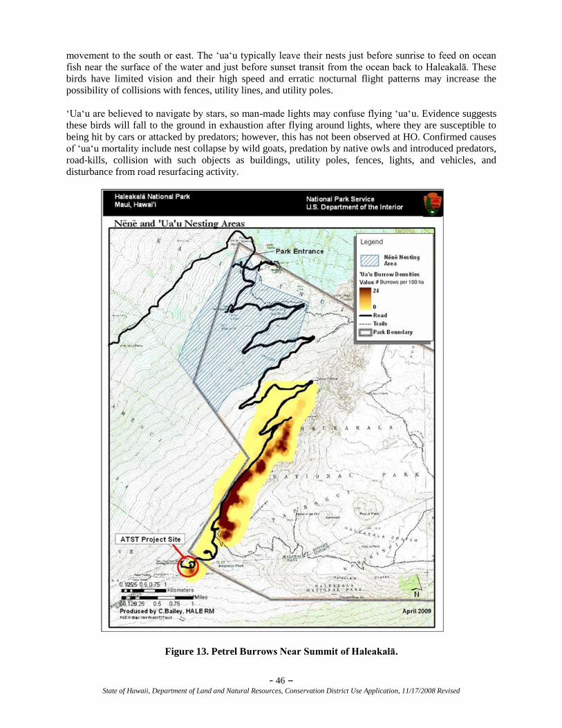
- 46 – State of Hawaii, Department of Land and Natural Resources, Conservation District Use Application, 11/17/2008 Revised
movement to the south or east. The ‗ua‗u typically leave their nests just before sunrise to feed on ocean
fish near the surface of the water and just before sunset transit from the ocean back to Haleakalā. These
birds have limited vision and their high speed and erratic nocturnal flight patterns may increase the
possibility of collisions with fences, utility lines, and utility poles.
‗Ua‗u are believed to navigate by stars, so man-made lights may confuse flying ‗ua‗u. Evidence suggests
these birds will fall to the ground in exhaustion after flying around lights, where they are susceptible to
being hit by cars or attacked by predators; however, this has not been observed at HO. Confirmed causes
of ‗ua‗u mortality include nest collapse by wild goats, predation by native owls and introduced predators,
road-kills, collision with such objects as buildings, utility poles, fences, lights, and vehicles, and
disturbance from road resurfacing activity.
Figure 13. Petrel Burrows Near Summit of Haleakalā.
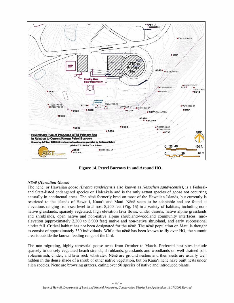
- 47 – State of Hawaii, Department of Land and Natural Resources, Conservation District Use Application, 11/17/2008 Revised
Figure 14. Petrel Burrows In and Around HO.
Nēnē (Hawaiian Goose)
The nēnē, or Hawaiian goose (Branta sandvicensis also known as Nesochen sandvicensis), is a Federal-
and State-listed endangered species on Haleakalā and is the only extant species of goose not occurring
naturally in continental areas. The nēnē formerly bred on most of the Hawaiian Islands, but currently is
restricted to the islands of Hawai‗i, Kaua‗i and Maui. Nēnē seem to be adaptable and are found at
elevations ranging from sea level to almost 8,200 feet (Fig. 15) in a variety of habitats, including non-
native grasslands, sparsely vegetated, high elevation lava flows, cinder deserts, native alpine grasslands
and shrublands, open native and non-native alpine shrubland-woodland community interfaces, mid-
elevation (approximately 2,300 to 3,900 feet) native and non-native shrubland, and early successional
cinder fall. Critical habitat has not been designated for the nēnē. The nēnē population on Maui is thought
to consist of approximately 330 individuals. While the nēnē has been known to fly over HO, the summit
area is outside the known feeding range of the bird.
The non-migrating, highly terrestrial goose nests from October to March. Preferred nest sites include
sparsely to densely vegetated beach strands, shrublands, grasslands and woodlands on well-drained soil,
volcanic ash, cinder, and lava rock substrates. Nēnē are ground nesters and their nests are usually well
hidden in the dense shade of a shrub or other native vegetation, but on Kaua‗i nēnē have built nests under
alien species. Nēnē are browsing grazers, eating over 50 species of native and introduced plants.
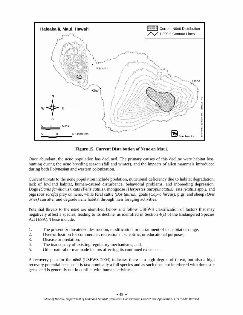
- 48 – State of Hawaii, Department of Land and Natural Resources, Conservation District Use Application, 11/17/2008 Revised
Figure 15. Current Distribution of Nēnē on Maui.
Once abundant, the nēnē population has declined. The primary causes of this decline were habitat loss,
hunting during the nēnē breeding season (fall and winter), and the impacts of alien mammals introduced
during both Polynesian and western colonization.
Current threats to the nēnē population include predation, nutritional deficiency due to habitat degradation,
lack of lowland habitat, human-caused disturbance, behavioral problems, and inbreeding depression.
Dogs (Canis familiaris), cats (Felis cattus), mongoose (Herpestes auropunctatus), rats (Rattus spp.), and
pigs (Sus scrofa) prey on nēnē, while feral cattle (Bos taurus), goats (Capra hircus), pigs, and sheep (Ovis
aries) can alter and degrade nēnē habitat through their foraging activities.
Potential threats to the nēnē are identified below and follow USFWS classification of factors that may
negatively affect a species, leading to its decline, as identified in Section 4(a) of the Endangered Species
Act (ESA). These include:
1. The present or threatened destruction, modification, or curtailment of its habitat or range,
2. Over-utilization for commercial, recreational, scientific, or educational purposes,
3. Disease or predation,
4. The inadequacy of existing regulatory mechanisms; and,
5. Other natural or manmade factors affecting its continued existence.
A recovery plan for the nēnē (USFWS 2004) indicates there is a high degree of threat, but also a high
recovery potential because it is taxonomically a full species and as such does not interbreed with domestic
geese and is generally not in conflict with human activities.
Haleakalā, Maui, Hawai‘i Current Nēnē Distribution
1,000 ft Contour Lines
Kihei
Kahului
Hana
5 5 Kilometers0
5 5 Miles0
N
E
S
W
Haleakalā, Maui, Hawai‘i Current Nēnē Distribution
1,000 ft Contour Lines
Kihei
Kahului
Hana
5 5 Kilometers0
5 5 Miles0
N
E
S
W
- 49 – State of Hawaii, Department of Land and Natural Resources, Conservation District Use Application, 11/17/2008 Revised
‘Ope‘ape‘a (Hawaiian Hoary Bat)
The ‗ope‗ape‗a, or Hawaiian hoary bat (Lasiurus cinereus semotus), is a federal-listed endangered species
that resides on the lower slopes of Haleakalā. The ‗ope‗ape‗a is found on Hawai‗i Island, Maui, O‗ahu,
Kaua‗i and Moloka‗i. On the island of Hawai‗i, most observations have been from between sea level and
7,500 feet ASL, although individuals have been recorded at elevations as high as 13,000 feet. On Maui,
the bat resides in the lowlands of the Haleakalā slopes. Even though several sightings have been reported
near HO, it is unlikely that the bat is a resident of the area, due to the relatively cold summit temperatures
and the lack of flying insects in the area, which is the preferred food source (AFRL 2005).
Other Introduced Fauna
Introduced fauna that could be observed within the summit area include the chukar (Alectoris chukar), the
feral goat (Capra hircus), the Polynesian rat (Rattus exulans), and the roof rat (Rattus rattus) (AFRL
2005). The Indian mongoose (Herpestes auropunctatus) is occasionally observed on the summit. These
species are not included on federal or state threatened or endangered lists.
INVERTEBRATE RESOURCES
The highest elevations of Haleakalā were once considered lifeless, but biologists have discovered a
diverse fauna of resident insects and spiders. These arthropods inhabit unique natural habitats on the bare
lava flows and cinder cones. Because they feed primarily on windblown organic materials, they form an
aeolian ecosystem.
In Hawai‗i, aeolian ecosystems are used to describe those that exist on non-weathered lava substrates
mostly, but not exclusively, found at high elevations (Medeiros, et al, 1994). On Haleakalā there is an
aeolian ecosystem extending up the summit from about the 7,550 feet elevation. It is characterized by
relatively low precipitation, porous lava substrates that retain relatively little moisture, little plant cover,
and high solar radiation. The dark, heat-absorbing cinder provides only slight protection from the extreme
temperatures, and thermal regulation and moisture conservation are critical adaptations of arthropods
occurring in this unusual habitat.
Due to the harsh environment, fewer insects are present at upper elevations on Haleakalā than are found
in the warm, moist lowlands. However, an exceptional assemblage of insects and spiders make their home
on the mountain's upper slopes. A survey and inventory of arthropod fauna was conducted for the 18.166
acres of HO in 2003 for the LRDP. In the 2003 study, several species were added to the previous
inventory site records. An additional survey including arthropod collection and analysis was conducted in
2005 at the Mees site for the proposed ATST Project (see FEIS Vol. II, C(1)-Arthropod Inventory). The
arthropod species that were collected in the 2005 study were typical of what had been found during
previous studies. No species were found that are locally unique to the site, nor were there any species
found whose habitat is threatened by normal observatory operations.
Through a desire to have a comprehensive arthropod inventory and in response to comments submitted
for the ATST DEIS published in September 2006, supplemental sampling for arthropods at the sites was
conducted in March 2007 (see FEIS Vol. II, Appendix C(2)-Supplemental Arthropod Sampling). The
goal was to detect additional species that may have been missed during previous samplings. This
additional survey, including night sampling, covers a seasonal component not included in the two
previous studies. The results of the arthropod survey indicate there are no special concerns or legal
constraints related to invertebrate resources in the project area. No invertebrate species listed as
endangered, threatened, or that are currently proposed for listing under either federal or State of Hawai‗i
endangered species statutes were found at the project site.
The diversity of the arthropod fauna at HO is somewhat less than what has been reported in adjacent,
undisturbed habitat. This is expected, in that buildings, roads, parking areas, and walkways occupy 40
percent of the site. However, the undisturbed habitat on the site that was sampled has an arthropod fauna
generally similar to what could be expected from other sites on the volcano with similar undisturbed
- 50 – State of Hawaii, Department of Land and Natural Resources, Conservation District Use Application, 11/17/2008 Revised
habitat. Most of the arthropods collected during the 2003 study were largely associated with vegetation at
the site. Observatory construction and operations have increased the suitability of some habitats for plants
and increased vegetation has probably caused an increase in the populations of some native arthropod
species.
The proposed project site represents an even smaller portion of the habitat overall on Haleakalā. The
Mees site is partly undisturbed. Native vegetation is more abundant, and the undisturbed nature of the
substrate provides excellent microhabitats for arthropods. Overall, the Mees site contains fewer
microhabitats than can be found elsewhere within HO.
Comments on the DEIS of September 2006, indicated that the collective invertebrate inventories obtained
at HO did not address certain ―Species of Concern‖ (SOC), although these were not specified (HALE,
2008). Therefore, USFWS was contacted to obtain a list of SOC for the ROI so that future surveys could
include those. It should be noted that SOC is an informal term. It is not defined in the Federal
Endangered Species Act. The term commonly refers to species that are declining or appear to be in need
of conservation. Many agencies and organizations maintain lists of at-risk species. These lists provide
essential information for land management planning and conservation efforts. According to the USFWS,
these species are not directly addressed by the USFWS Section 7 consultations (D. Greenlee, USFWS,
personal communication, April 2009). Using an updated (2008) version of the Hawai‗i Biodiversity and
Mapping Program data set, which includes map locations for SOC, the USFWS imported the data to the
Hawai‗i Biodiversity and Mapping Program and no invertebrate SOC were identified in the ROI for the
proposed ATST Project (D. Greenlee, USFWS, personal communication, April 2009).
In response to comments about SOC that might have been missed during earlier surveys, a third arthropod
survey was conducted in June 2009 (See FEIS Vol. II, Appendix C(3)-Arthropod Inventory and
Assessment, HALE and HO). There were a number of additional species collected, including one
endemic carabid beetle (Mecyclothorax), and two species of long horn beetles of the genus Plagithmysus.
Carabid beetle populations appear to be impacted when alien predators are introduced to their habitats and
their conservation is considered important. The two species of long-horn beetles are considered rare and
are infrequently collected.
One of the biggest concerns of past evaluations was the presence of ants. None were found during this
study within HO, but ants are reported from nearby National Park facilities. Since ants are not a common
endemic species in Hawai‗i (Wilson & Taylor, 1967), introduced species are often successful in the
favorable environment. The Argentine ant is one of about 60 species that has flourished since invasions of
biological organisms were aided by humans to enter in the Hawaiian Islands. With HALE‘s large visitor
population and vehicular traffic from lower elevations, it is not surprising that several of these predatory
ant species have found their way into the Park. The invasive potential of the Argentine ant requires active
management by HALE to prevent further spread of the species, including such methods as inspection,
when warranted, of vehicles, freight, and soils that may contain individuals capable of colonizing areas.
With some practical precautions, HO should remain ant free.
The Yellow-jacket is also a predator within the upper shrubland of HALE and at HO that has an impact
on the varied arthropods on which it preys. It poses a substantial threat to biodiversity within the Park,
and since its introduction to Maui in 1978, it has experienced a population explosion in subsequent years
(Gambino, et. al., 1990). The identity of its diet and location in HALE (Gambino, 1992) suggests that it is
a threat to biodiversity in wide areas of the Park and HO, at lower and upper elevations. In particular, this
predator is found within the ROI for the proposed ATST Project, where active management for
prevention of widened invasion is required. With a capability to colonize in massive numbers (ibid,
1990), any reproducing individuals of this species introduced to the upper slopes of HALE could prove
damaging to the biodiversity of the Park taxonomy. Therefore, active management of this species is
needed at HO in addition to HALE. It should be noted, however, that none were identified in the 2009
survey at the Park road entrance station (see FEIS Vol. II, Appendix C(3).
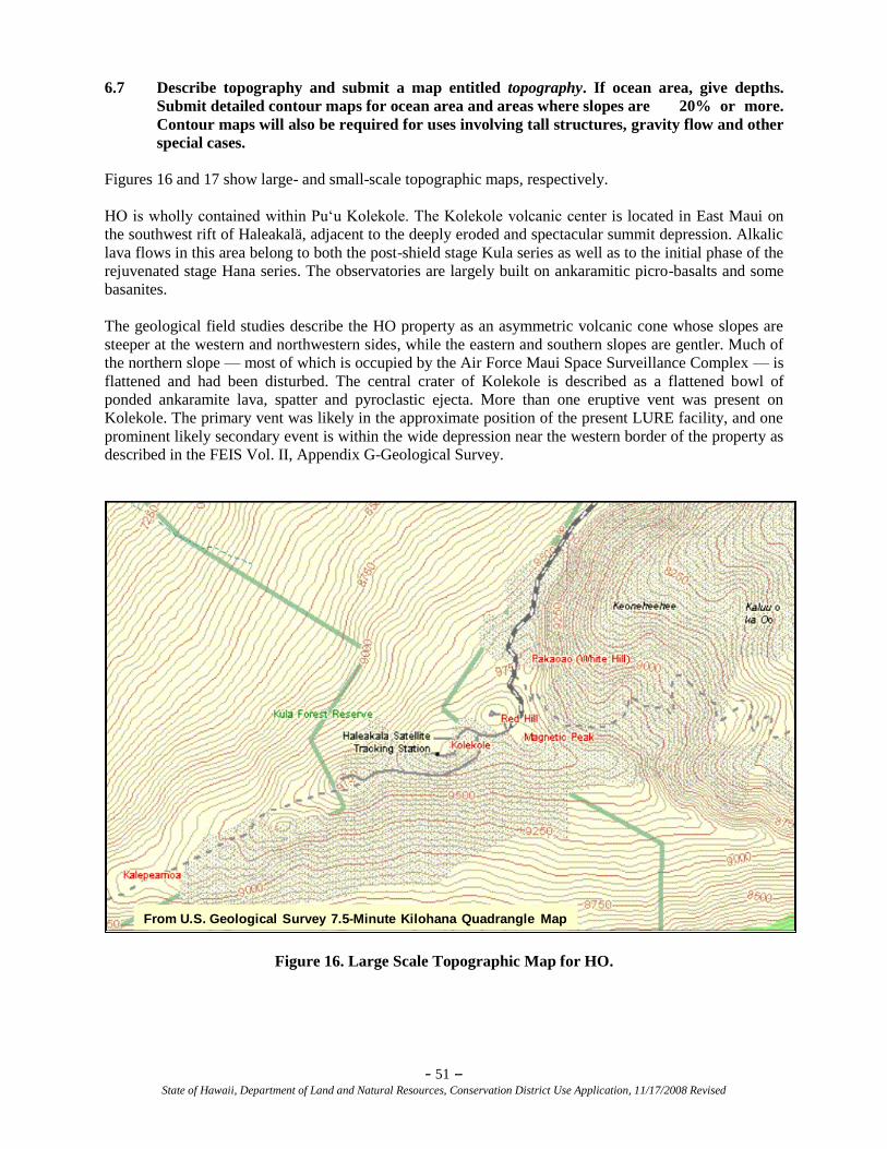
- 51 – State of Hawaii, Department of Land and Natural Resources, Conservation District Use Application, 11/17/2008 Revised
6.7 Describe topography and submit a map entitled topography. If ocean area, give depths.
Submit detailed contour maps for ocean area and areas where slopes are 20% or more.
Contour maps will also be required for uses involving tall structures, gravity flow and other
special cases.
Figures 16 and 17 show large- and small-scale topographic maps, respectively.
HO is wholly contained within Pu‗u Kolekole. The Kolekole volcanic center is located in East Maui on
the southwest rift of Haleakalä, adjacent to the deeply eroded and spectacular summit depression. Alkalic
lava flows in this area belong to both the post-shield stage Kula series as well as to the initial phase of the
rejuvenated stage Hana series. The observatories are largely built on ankaramitic picro-basalts and some
basanites.
The geological field studies describe the HO property as an asymmetric volcanic cone whose slopes are
steeper at the western and northwestern sides, while the eastern and southern slopes are gentler. Much of
the northern slope — most of which is occupied by the Air Force Maui Space Surveillance Complex — is
flattened and had been disturbed. The central crater of Kolekole is described as a flattened bowl of
ponded ankaramite lava, spatter and pyroclastic ejecta. More than one eruptive vent was present on
Kolekole. The primary vent was likely in the approximate position of the present LURE facility, and one
prominent likely secondary event is within the wide depression near the western border of the property as
described in the FEIS Vol. II, Appendix G-Geological Survey.
From U.S. Geological Survey 7.5-Minute Kilohana Quadrangle Map
Figure 16. Large Scale Topographic Map for HO.
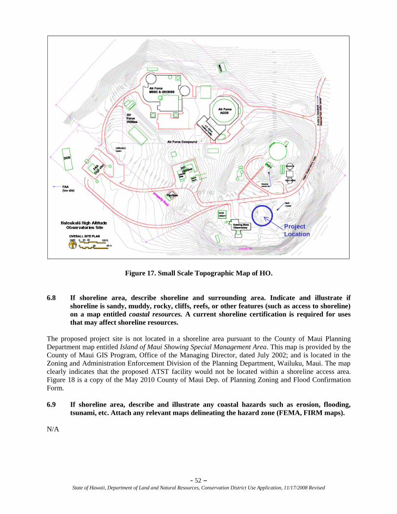
- 52 – State of Hawaii, Department of Land and Natural Resources, Conservation District Use Application, 11/17/2008 Revised
Project
Location
Figure 17. Small Scale Topographic Map of HO.
6.8 If shoreline area, describe shoreline and surrounding area. Indicate and illustrate if
shoreline is sandy, muddy, rocky, cliffs, reefs, or other features (such as access to shoreline)
on a map entitled coastal resources. A current shoreline certification is required for uses
that may affect shoreline resources.
The proposed project site is not located in a shoreline area pursuant to the County of Maui Planning
Department map entitled Island of Maui Showing Special Management Area. This map is provided by the
County of Maui GIS Program, Office of the Managing Director, dated July 2002; and is located in the
Zoning and Administration Enforcement Division of the Planning Department, Wailuku, Maui. The map
clearly indicates that the proposed ATST facility would not be located within a shoreline access area.
Figure 18 is a copy of the May 2010 County of Maui Dep. of Planning Zoning and Flood Confirmation
Form.
6.9 If shoreline area, describe and illustrate any coastal hazards such as erosion, flooding,
tsunami, etc. Attach any relevant maps delineating the hazard zone (FEMA, FIRM maps).
N/A
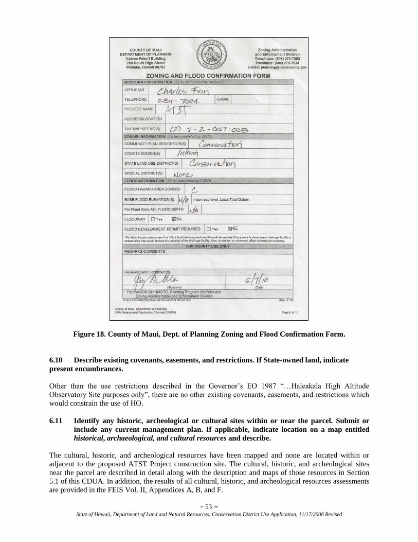
- 53 – State of Hawaii, Department of Land and Natural Resources, Conservation District Use Application, 11/17/2008 Revised
Figure 18. County of Maui, Dept. of Planning Zoning and Flood Confirmation Form.
6.10 Describe existing covenants, easements, and restrictions. If State-owned land, indicate
present encumbrances.
Other than the use restrictions described in the Governor‘s EO 1987 ―…Haleakala High Altitude
Observatory Site purposes only‖, there are no other existing covenants, easements, and restrictions which
would constrain the use of HO.
6.11 Identify any historic, archeological or cultural sites within or near the parcel. Submit or
include any current management plan. If applicable, indicate location on a map entitled
historical, archaeological, and cultural resources and describe.
The cultural, historic, and archeological resources have been mapped and none are located within or
adjacent to the proposed ATST Project construction site. The cultural, historic, and archeological sites
near the parcel are described in detail along with the description and maps of those resources in Section
5.1 of this CDUA. In addition, the results of all cultural, historic, and archeological resources assessments
are provided in the FEIS Vol. II, Appendices A, B, and F.
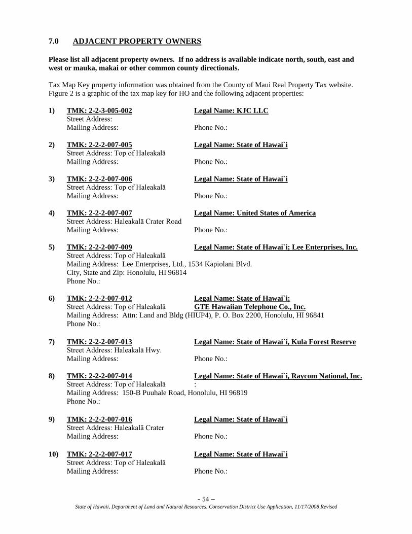
- 54 – State of Hawaii, Department of Land and Natural Resources, Conservation District Use Application, 11/17/2008 Revised
7.0 ADJACENT PROPERTY OWNERS
Please list all adjacent property owners. If no address is available indicate north, south, east and
west or mauka, makai or other common county directionals.
Tax Map Key property information was obtained from the County of Maui Real Property Tax website.
Figure 2 is a graphic of the tax map key for HO and the following adjacent properties:
1) TMK: 2-2-3-005-002 Legal Name: KJC LLC
Street Address:
Mailing Address: Phone No.:
2) TMK: 2-2-2-007-005 Legal Name: State of Hawai`i
Street Address: Top of Haleakalā
Mailing Address: Phone No.:
3) TMK: 2-2-2-007-006 Legal Name: State of Hawai`i
Street Address: Top of Haleakalā
Mailing Address: Phone No.:
4) TMK: 2-2-2-007-007 Legal Name: United States of America
Street Address: Haleakalā Crater Road
Mailing Address: Phone No.:
5) TMK: 2-2-2-007-009 Legal Name: State of Hawai`i; Lee Enterprises, Inc.
Street Address: Top of Haleakalā
Mailing Address: Lee Enterprises, Ltd., 1534 Kapiolani Blvd.
City, State and Zip: Honolulu, HI 96814
Phone No.:
6) TMK: 2-2-2-007-012 Legal Name: State of Hawai`i;
Street Address: Top of Haleakalā GTE Hawaiian Telephone Co., Inc.
Mailing Address: Attn: Land and Bldg (HIUP4), P. O. Box 2200, Honolulu, HI 96841
Phone No.:
7) TMK: 2-2-2-007-013 Legal Name: State of Hawai`i, Kula Forest Reserve
Street Address: Haleakalā Hwy.
Mailing Address: Phone No.:
8) TMK: 2-2-2-007-014 Legal Name: State of Hawai`i, Raycom National, Inc.
Street Address: Top of Haleakalā :
Mailing Address: 150-B Puuhale Road, Honolulu, HI 96819
Phone No.:
9) TMK: 2-2-2-007-016 Legal Name: State of Hawai`i
Street Address: Haleakalā Crater
Mailing Address: Phone No.:
10) TMK: 2-2-2-007-017 Legal Name: State of Hawai`i
Street Address: Top of Haleakalā
Mailing Address: Phone No.:
- 55 – State of Hawaii, Department of Land and Natural Resources, Conservation District Use Application, 11/17/2008 Revised
8.0 REFERENCES
AFRL [U. S. Air Force Research Laboratory]. April 2005. ―Draft Environmental Assessment: Proposed
Advanced Electro-Optical System (AEOS) Mirror Coating Facility at the Maui Space
Surveillance Complex (MSSC), Haleakalā, Maui, Hawai‗i‖. Prepared by Belt Collins.
Bushnell, K.W. and H.H. Hammatt. 2002. ―An Archaeological Inventory Survey of 1.5 Acres of the
University of Hawai‗i Facility at Haleakalā, Papa‗anui Ahupua‗a, Makawao District, East Maui
(TMK: 2-2-07: 8)‖, for KC Environmental, Inc., by Cultural Surveys Hawai‗i.
Chatters, J. C. July 1991. ―Cultural Resources Inventory and Evaluation for Science City, Conducted for
Expansion of the Maui Space Surveillance Site, Haleakalā, Maui, Hawai‗i‖. Prepared for the
U. S. Air Force Headquarters Space Division Air Systems Command, Los Angeles Air Force
Base. Prepared by the Pacific Northwest Laboratory (Batelle Memorial Institute).
CKM [CKM Cultural Resources, LLC]
______ 2006. Cultural Resource Evaluation and Traditional Practices of the Proposed Advanced
Technology Solar Telescope (ATST) at Haleakalä High Altitude Observatories. Final Report.
January 2006.
______ 2003. ―Cultural Resources Evaluation for the Summit of Haleakalā‖. March 2003.
______ 2002. Traditional Practices Assessment for the Summit of Haleakalā, December 2002.
DLNR [State of Hawai‗i, Department of Land and Natural Resources]
______ Conservation Lands. Web site: http://hawaii.gov/dlnr/occl/conservation.
Web site accessed June 17, 2009.
______ Hawai‗i State Parks, Polipoli Spring State Recreation Area.
Web site: http://www.hawaiistateparks.org/parks/maui/Index.cfm?park_id=39
Web site accessed February 26, 2008.
______ 2006. Letter to Erik Fredericksen, Xamanek Researches, from Peter Young, DLNR. Subject:
National Historic Preservation Act (NHPA) Section 106 Review – Preservation Plan for 11
Sites at Science City, Haleakalā, Papa‗anui Ahupua‗a, Makawao, Island o Maui, TMK: (2)2-2-
007:por. 008.
______ 2003. Doc. No. 0307MK03, Log No. 2003.1138, Letter from P. Holly McEldowney,
Acting Administrator, to Erik Fredericksen, Xamanek Researches, dated July 10, 2003.
DOI [U. S. Department of the Interior].
______ 2007. Web site: http://www.doi.gov/ohr/nativehawaiians/list.html.
Web site accessed January 16, 2008.
______ 1994. ―Guidelines for Evaluating and Documenting Traditional
Cultural Properties‖, National Register Bulletin 38.
EO [Executive Order] 1987. State of Hawai‗i, Setting Aside Land for Public Purposes. December 12,
1961.
FTF EA [Faulkes Telescope Facility Environmental Assessment]. May 2001.―Final Environmental
Assessment/Negative Declaration for the Faulkes Telescope Facility at Haleakalā, Maui,
Hawai‗i‖. Prepared by KC Environmental, Inc.
- 56 – State of Hawaii, Department of Land and Natural Resources, Conservation District Use Application, 11/17/2008 Revised
Fredericksen, Erik and Fredericksen, Demaris. 2003. ―Archaeological Inventory Survey of 18.1-acre
parcel at Science City, Haleakalā Crater, Papa‗anui Ahupua‗a, Makawao District,
Maui Island (TMK: 2-2-07: por. 8)‖, Prepared for Mr. Charles Fein, KC Environmental, Inc.,
Makawao, Maui.
Fukunaga and Associates. 2003. ―State Water Project Plans, Hawai‗i Water Plan‖. Volume 4, SWPPP for
Islands of Lanai/Maui/Molokai. February 2003.
Gambino, Parker, et. al. 1990. ―Invasion and Colonization of Upper Elevations on East Maui (Hawai‗i)
by Vespula pensylvanica”.
Gambino, Parker, 1992. ―Yellow-Jacket (Vespula pensylvanica) Predation at Hawai‗i Volcanoes and
Haleakalā National Park‘s: Identity of Prey Items‖.
HALE [Haleakalā National Park]. 2003. ―Hawaiian Petrels Near the Haleakalā Observatories: A Report
to KC Environmental, Inc. for Preparation of a Long-Range Development Plan‖, Prepared by
Cathleen Natividad Bailey, HALE Wildlife Biologist, Endangered Species Management.
Jackson, Frances. University of Hawai‗i Archivist. ―Military Use of Haleakalā National Park‖. Hawaiian
Journal of History, Vol. 6, 1972.
Kauhi, Greg. 2005. Email to Mike Maberry, UH IfA. August 11, 2005.
Krauss, B. 1988, Keneti: South Seas Adventures of Kenneth Emory. University of Hawai‗i, Honolulu,
Hawai‗i.
Medeiros, A.C., F.R. Cole, and L.L. Loope. 1994. Impacts of biological invasions on the management
and recovery of rare plants in Haleakala National Park, Maui, Hawaiian Islands. In Restoration
of Endangered Species, M. Bowles and C.J. Whelan (eds.).
NPS [National Park Service]. Ethnographic Study. ―An Ethnographic Overview and Study of the Cultural
Impacts of Commercial Air Tours Over Haleakalā National Park, Island of Maui‖. Prasad, U.,
Ph.D., Tomonari-Tuggle, M.J., M.A., International Archaeological Research Institute, Inc.,
June 2008.
OEQC. [Hawai‗i State Department of Health Office of Environmental Quality Control] 1997. Guidelines
for Assessing Cultural Impacts. Electronic Document,
http://www.state.hi.us/health/oeqc/guidance/cultural.htm. Web site accessed April 2007.
Rosendahl, Margaret L. K. 1978. Preliminary Overview of Archaeological Resources at Haleakalä
National Park. Department of Anthropology, B. P. Bishop Museum, Honolulu, HI.
UH IfA [University of Hawai‗i, Institute for Astronomy].
______ 2005. ―Haleakalā High Altitude Observatory Site Long Range Development Plan (LRDP)‖.
KC Environmental, January 2005. Web site: http://www.ifa.hawaii.edu/haleakala/LRDP/.
______ 2005a. ―Haleakalā High Altitude Observatory Stormwater Erosion Report‖.
Prepared by Tetra Tech, Inc., July 2005.
______ 2005b. Institute For Astronomy, Haleakalā Division, ―Hazardous Material and Hazardous
Waste Management Program, Rev. Dec. 1, 2005‖.
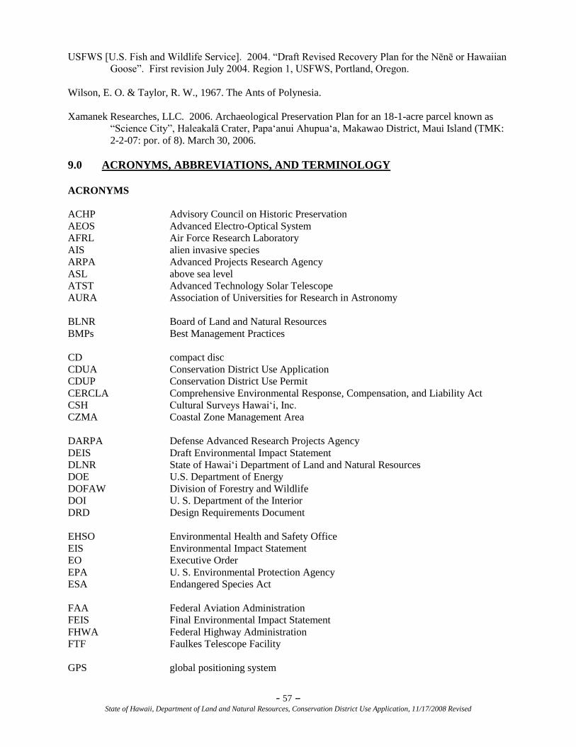
- 57 – State of Hawaii, Department of Land and Natural Resources, Conservation District Use Application, 11/17/2008 Revised
USFWS [U.S. Fish and Wildlife Service]. 2004. ―Draft Revised Recovery Plan for the Nēnē or Hawaiian
Goose‖. First revision July 2004. Region 1, USFWS, Portland, Oregon.
Wilson, E. O. & Taylor, R. W., 1967. The Ants of Polynesia.
Xamanek Researches, LLC. 2006. Archaeological Preservation Plan for an 18-1-acre parcel known as
―Science City‖, Haleakalā Crater, Papa‗anui Ahupua‗a, Makawao District, Maui Island (TMK:
2-2-07: por. of 8). March 30, 2006.
9.0 ACRONYMS, ABBREVIATIONS, AND TERMINOLOGY
ACRONYMS
ACHP Advisory Council on Historic Preservation
AEOS Advanced Electro-Optical System
AFRL Air Force Research Laboratory
AIS alien invasive species
ARPA Advanced Projects Research Agency
ASL above sea level
ATST Advanced Technology Solar Telescope
AURA Association of Universities for Research in Astronomy
BLNR Board of Land and Natural Resources
BMPs Best Management Practices
CD compact disc
CDUA Conservation District Use Application
CDUP Conservation District Use Permit
CERCLA Comprehensive Environmental Response, Compensation, and Liability Act
CSH Cultural Surveys Hawai‗i, Inc.
CZMA Coastal Zone Management Area
DARPA Defense Advanced Research Projects Agency
DEIS Draft Environmental Impact Statement
DLNR State of Hawai‗i Department of Land and Natural Resources
DOE U.S. Department of Energy
DOFAW Division of Forestry and Wildlife
DOI U. S. Department of the Interior
DRD Design Requirements Document
EHSO Environmental Health and Safety Office
EIS Environmental Impact Statement
EO Executive Order
EPA U. S. Environmental Protection Agency
ESA Endangered Species Act
FAA Federal Aviation Administration
FEIS Final Environmental Impact Statement
FHWA Federal Highway Administration
FTF Faulkes Telescope Facility
GPS global positioning system
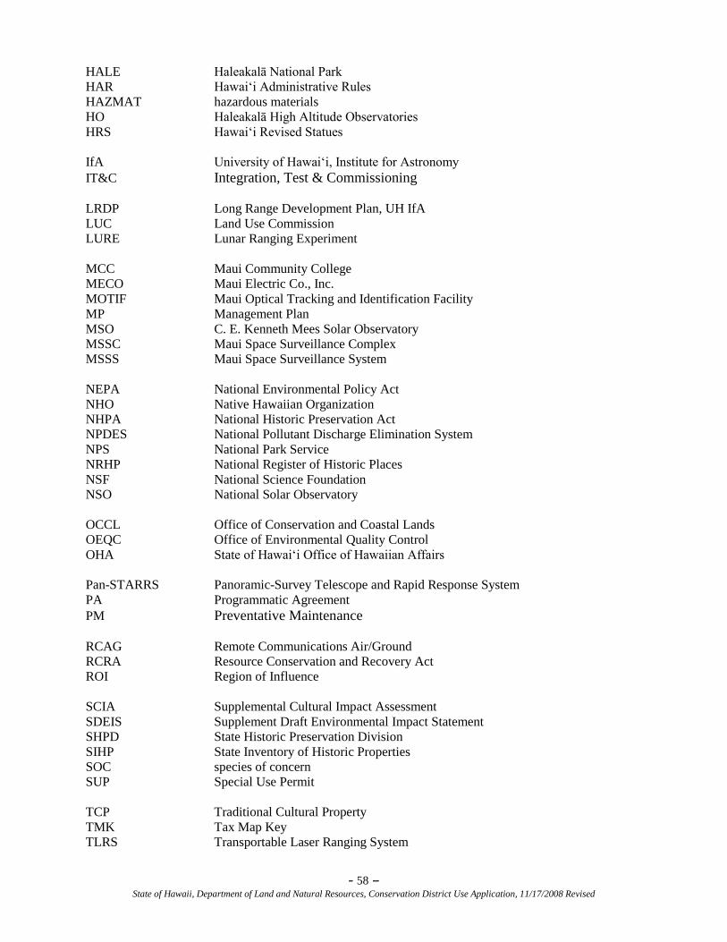
- 58 – State of Hawaii, Department of Land and Natural Resources, Conservation District Use Application, 11/17/2008 Revised
HALE Haleakalā National Park
HAR Hawai‗i Administrative Rules
HAZMAT hazardous materials
HO Haleakalā High Altitude Observatories
HRS Hawai‗i Revised Statues
IfA University of Hawai‗i, Institute for Astronomy
IT&C Integration, Test & Commissioning
LRDP Long Range Development Plan, UH IfA
LUC Land Use Commission
LURE Lunar Ranging Experiment
MCC Maui Community College
MECO Maui Electric Co., Inc.
MOTIF Maui Optical Tracking and Identification Facility
MP Management Plan
MSO C. E. Kenneth Mees Solar Observatory
MSSC Maui Space Surveillance Complex
MSSS Maui Space Surveillance System
NEPA National Environmental Policy Act
NHO Native Hawaiian Organization
NHPA National Historic Preservation Act
NPDES National Pollutant Discharge Elimination System
NPS National Park Service
NRHP National Register of Historic Places
NSF National Science Foundation
NSO National Solar Observatory
OCCL Office of Conservation and Coastal Lands
OEQC Office of Environmental Quality Control
OHA State of Hawai‗i Office of Hawaiian Affairs
Pan-STARRS Panoramic-Survey Telescope and Rapid Response System
PA Programmatic Agreement
PM Preventative Maintenance
RCAG Remote Communications Air/Ground
RCRA Resource Conservation and Recovery Act
ROI Region of Influence
SCIA Supplemental Cultural Impact Assessment
SDEIS Supplement Draft Environmental Impact Statement
SHPD State Historic Preservation Division
SIHP State Inventory of Historic Properties
SOC species of concern
SUP Special Use Permit
TCP Traditional Cultural Property
TMK Tax Map Key
TLRS Transportable Laser Ranging System
- 59 – State of Hawaii, Department of Land and Natural Resources, Conservation District Use Application, 11/17/2008 Revised
UH University of Hawai‗i
USFWS U.S. Fish & Wildlife Service
ABBREVIATIONS AND TERMINOLOGY
‗ahinahina Haleakalā Silversword, Argyroxiphium sandwicense
subsp. Macrocephalum. Low-growing plant found only in volcanic
craters on Hawai‗i having rosettes of narrow pointed silver-green
leaves and clusters of profuse red-purple flowers on a tall stem
‗āina land
ahu altar or shrine
akamai smart, clever
centimeter A metric unit of measure where 2.5 centimeters equals 1 inch
Haleakalā House of the Sun; mountain at 10,023 ft ASL on island of Maui
haole foreigner
haumana students
HazMat hazardous material
Hawaiian Petrel ‗Ua‗u, Pterodoma phaeopygia sandwichensis
Hawaiian Goose Nēnē, Branta sandvicensis or Nesochen sandvicensis
Hawaiian Hoary Bat ‗Ope ‗ape ‗a, Lasiurus cinereus semotus
Haleakalā Silversword ‗ahinahina, Argyroxiphium sandwicense subsp. Macrocephalum Low-
growing plant found only in volcanic craters on Hawai‗i having rosettes
of narrow pointed silver-green leaves and clusters of profuse red-purple
flowers on a tall stem
Hinala‗anui Name dedicated to West-facing ahu on Haleakalā
Honua‗lua area of Maui once inhabited by Hawaiian people
ho‗omahanahana dedication or ―warming‖ offering
ho‗oponopono to ―make right
I na ‗ōiwi Hawai‗i To the native caretakers of the land, please enter.
Aloha ‗āina
Indian mongoose Herpestes auropunctatus
kahu clergyman
- 60 – State of Hawaii, Department of Land and Natural Resources, Conservation District Use Application, 11/17/2008 Revised
Kahuna Po‗o head priest
ko‗a ceremonial rock formations
Kolekole Land section in Kilohana and Mākena.
(1) One account explicates that Kolekole was named after the first Kole,
for its similarity in the abundance of the rusty hue.
(2) The second account stated that Kolekole means to ―talk story‖. Some
believe it was an area where Kahuna Po‘o or High Priests would come to
delve over tough issues.
Kumu Hula hula master
kupuna elder
ma‗a familiar or accustomed
Makahiki Ancient festival beginning about the middle of October and lasting about
four months, with sports and religious festivities and taboo on war
makana aloha gift of friendship
mana spirit
Māui demi-god
Maui Nui O Kama the greater Maui
mele song
meter A metric unit of measure that equals 39.37 inches
mo‗olelo stories
na poāo kāhuna priest
Nēnē Hawaiian Goose, Branta sandvicensis or Nesochen sandvicensis
o‗mana‗o remembrances, recollections
oli chants
‗Ope ‗ape ‗a Hawaiian Hoary Bat, Lasiurus cinereus semotus
‗opihi limpet, Cellana spp.
Pā‗ele Kū Ai I Ka Moku Name dedicated to East-facing ahu on Haleakalā
Pa Ka‘oao White Hill
Pele Goddess of the Volcano
piko navel
- 61 – State of Hawaii, Department of Land and Natural Resources, Conservation District Use Application, 11/17/2008 Revised
Poli‗ahu goddess of snow
pu‗u hill
Pu‗u Honua sacred refuge, or place of peace
Pu‗u Kolekole land near the summit of Haleakalā
Pu‗u Ula‗ula Red Hill Overlook
Star Compass A learning tool used to teach direction without instruments: The star
compass is the basic mental construct for navigation, to help one
memorize what is needed to navigate.
‗ua‗u Hawaiian Petrel, Pterodoma phaeopygia sandwichensis
Wahi Pana a legendary place

- 62 – State of Hawaii, Department of Land and Natural Resources, Conservation District Use Application, 11/17/2008 Revised
This page intentionally left blank.
APPENDICES for
Conservation District Use Application (CDUA)
for the
Advanced Technology Solar Telescope
Haleakalā High Altitude Observatory Site
Haleakalā, Maui, HI
Appendix A Schematic Design of the Support Facilities for the ATST
(separate document)
Appendix B ATST Preliminary Construction Plan
Appendix C ATST Support Facilities Design Requirements Document
Appendix D ATST Maintenance Plan
Appendix E Programmatic Agreement for the ATST

THIS PAGE INTENTIONALLY LEFT BLANK
Appendix A
APPENDIX A
SCHEMATIC DESIGN OF THE SUPPORT FACILITIES FOR THE ATST
(SEPARATE DOCUMENT)

Appendix A
THIS PAGE INTENTIONALLY LEFT BLANK
APPENDIX B
PRELIMINARY CONSTRUCTION PLAN
for the
Advanced Technology Solar Telescope
Haleakalā High Altitude Observatory Site
Haleakalā, Maui, HI

THIS PAGE INTENTIONALLY LEFT BLANK
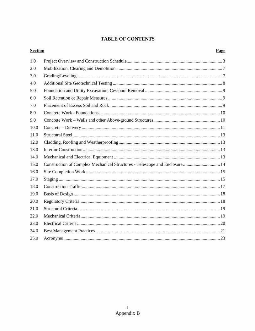
1 Appendix B
TABLE OF CONTENTS
Section Page
1.0 Project Overview and Construction Schedule................................................................................... 3
2.0 Mobilization, Clearing and Demolition ............................................................................................ 7
3.0 Grading/Leveling .............................................................................................................................. 7
4.0 Additional Site Geotechnical Testing ............................................................................................... 8
5.0 Foundation and Utility Excavation, Cesspool Removal ................................................................... 9
6.0 Soil Retention or Repair Measures ................................................................................................... 9
7.0 Placement of Excess Soil and Rock .................................................................................................. 9
8.0 Concrete Work - Foundations ......................................................................................................... 10
9.0 Concrete Work – Walls and other Above-ground Structures ......................................................... 10
10.0 Concrete – Delivery ........................................................................................................................ 11
11.0 Structural Steel ................................................................................................................................ 13
12.0 Cladding, Roofing and Weatherproofing ........................................................................................ 13
13.0 Interior Construction ....................................................................................................................... 13
14.0 Mechanical and Electrical Equipment ............................................................................................ 13
15.0 Construction of Complex Mechanical Structures - Telescope and Enclosure ................................ 14
16.0 Site Completion Work .................................................................................................................... 15
17.0 Staging ............................................................................................................................................ 15
18.0 Construction Traffic ........................................................................................................................ 17
19.0 Basis of Design ............................................................................................................................... 18
20.0 Regulatory Criteria .......................................................................................................................... 18
21.0 Structural Criteria ............................................................................................................................ 19
22.0 Mechanical Criteria ......................................................................................................................... 19
23.0 Electrical Criteria ............................................................................................................................ 20
24.0 Best Management Practices ............................................................................................................ 21
25.0 Acronyms ........................................................................................................................................ 23
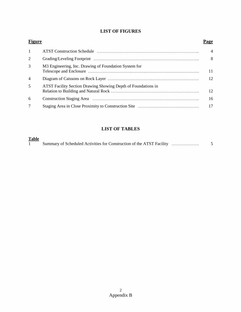
2 Appendix B
LIST OF FIGURES
Figure Page
1 ATST Construction Schedule …………………………………………………………….. 4
2 Grading/Leveling Footprint ………………………………………………………………. 8
3 M3 Engineering, Inc. Drawing of Foundation System for
Telescope and Enclosure ………………………………….………………………………. 11
4 Diagram of Caissons on Rock Layer ……………………………………………………… 12
5 ATST Facility Section Drawing Showing Depth of Foundations in
Relation to Building and Natural Rock ……………………………………………………. 12
6 Construction Staging Area ……………………………………………………………….. 16
7 Staging Area in Close Proximity to Construction Site …………………………………… 17
LIST OF TABLES
Table
1 Summary of Scheduled Activities for Construction of the ATST Facility ………………. 5
3 Appendix B
PRELIMINARY CONSTRUCTION PLAN
1.0 Project Overview and Construction Schedule
The following description corresponds to the Advanced Technology Solar Telescope (ATST) Final
Environmental Impact Statement (FEIS) Section 2.4.3, pages 2-21 to 2-35 that describes the construction
of the ATST Project at the Mees site location. The FEIS also provides references to appendices and
corollary documents that may be useful to the reviewer of the Conservation District Use Application
(CDUA). For the purposes of this CDUA, the description is revised to suit the requirements of the CDUA
Preliminary Construction Plan and also to focus on the specific site location that is identified in the
Record of Decision for the FEIS. This written description relates closely to the graphic depiction of the
ATST facility in the Schematic Design Drawings (DWG-00124) provided as CDUA Appendix B.
Specific references to those drawings are provided where appropriate. Approximate durations of the
progressive stages of construction are provided in Table 1, which also provides a synopsis of the
construction activities.
Construction of the ATST Project would involve: land clearing and demolition; grading/leveling;
excavation and soil placement; geotechnical testing; concrete foundations and walls; structural steel;
cladding and weatherproofing; mechanical and electrical work; staging and assembly of complex
mechanical structures (telescope & rotating enclosure); paving and other final site improvements.
Construction Schedule
The earliest possible construction start for the ATST facility would be during the Federal fiscal year 2010,
which is October 1, 2009 to September 30, 2010. Depending on the timing of permitting and the window
for site work allowed by biological and other mitigations, excavation and construction of the foundations
and pier would take place in the first year of construction, followed by erection of the telescope pier,
buiding structures and enclosure in the second, third, and fourth years. Once the enclosure is in position,
the telescope mount would be installed and the majority of the remaining work would be inside the
buildings and enclosure. The optics, control systems, and instrumentation would progress toward the end
of construction and into integration, testing, and commissioning of the various systems and instruments.
The final phase of construction would be the verification of the science and the transition into a fully
operational system. The site would be in full operation during the 7th year after construction begins.
Figure 1 shows an overall graphic timeline of these activities. Table 1 provides a more task-specific
breakdown of the anticipated construction activities.
Decommissioning of facilities constructed with the financial assistance of the National Science
Foundation is determined on a case-by-case basis. Decommissioning is taken into consideration as part of
life-cycle project planning. With regard to the ATST Project, NSF anticipates that the estimated lifetime
of the telescope would be at least 45 years (spanning two 22-year solar cycles) after it becomes
operational (if funding for construction is approved). As discussed in the FEIS, NSF would consider
decommissioning, deconstruction or divestment of the ATST Project at the end of its productive lifetime.
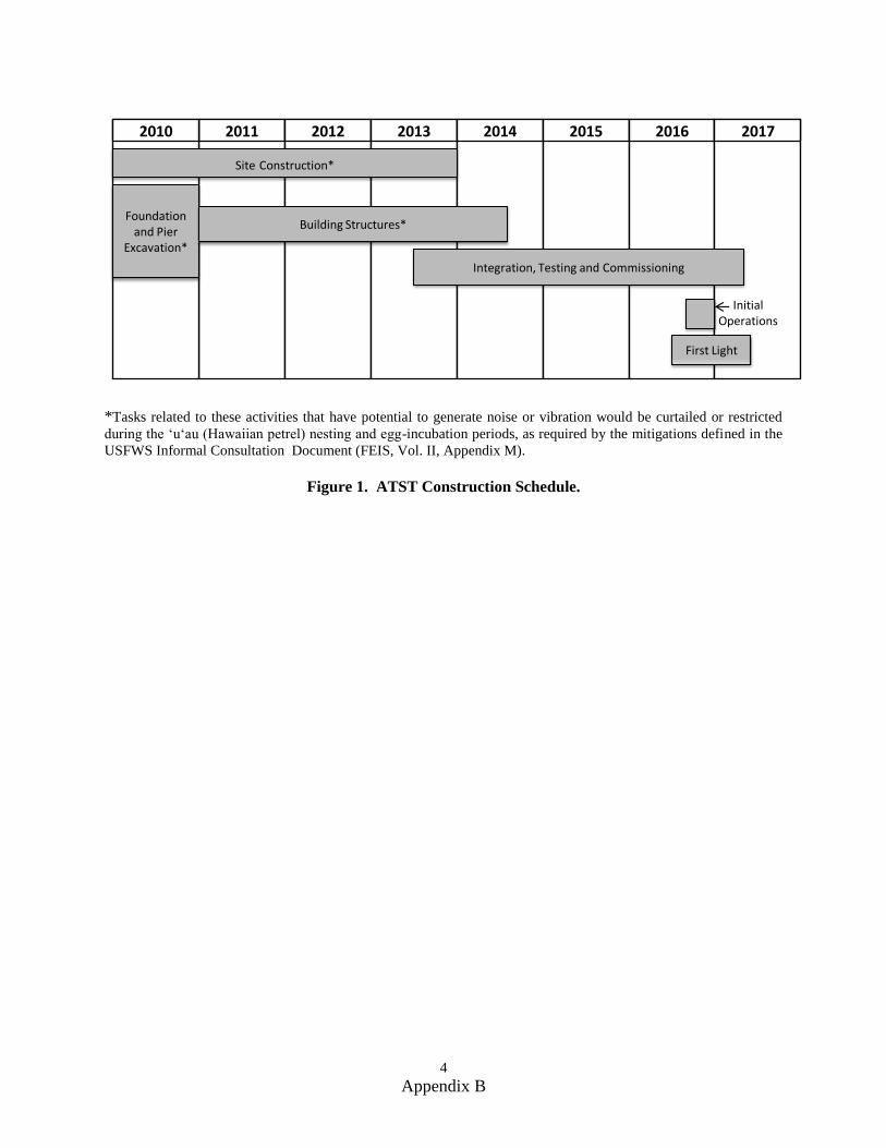
4 Appendix B
2011 2012 2013 2014 20152010 2016 2017
Site Construction*
Foundation and Pier
Excavation*
Building Structures*
Integration, Testing and Commissioning
First Light
InitialOperations
*Tasks related to these activities that have potential to generate noise or vibration would be curtailed or restricted
during the ‘u‘au (Hawaiian petrel) nesting and egg-incubation periods, as required by the mitigations defined in the
USFWS Informal Consultation Document (FEIS, Vol. II, Appendix M).
Figure 1. ATST Construction Schedule.
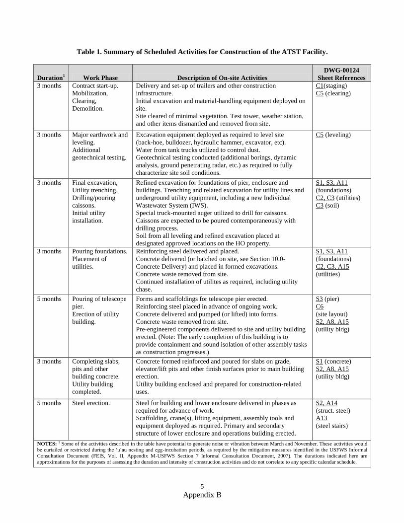
5 Appendix B
Table 1. Summary of Scheduled Activities for Construction of the ATST Facility.
Duration1
Work Phase Description of On-site Activities
DWG-00124
Sheet References
3 months Contract start-up.
Mobilization,
Clearing,
Demolition.
Delivery and set-up of trailers and other construction
infrastructure.
Initial excavation and material-handling equipment deployed on
site.
Site cleared of minimal vegetation. Test tower, weather station,
and other items dismantled and removed from site.
C1(staging)
C5 (clearing)
3 months Major earthwork and
leveling.
Additional
geotechnical testing.
Excavation equipment deployed as required to level site
(back-hoe, bulldozer, hydraulic hammer, excavator, etc).
Water from tank trucks utilized to control dust.
Geotechnical testing conducted (additional borings, dynamic
analysis, ground penetrating radar, etc.) as required to fully
characterize site soil conditions.
C5 (leveling)
3 months Final excavation,
Utility trenching.
Drilling/pouring
caissons.
Initial utility
installation.
Refined excavation for foundations of pier, enclosure and
buildings. Trenching and related excavation for utility lines and
underground utility equipment, including a new Individual
Wastewater System (IWS).
Special truck-mounted auger utilized to drill for caissons.
Caissons are expected to be poured contemporaneously with
drilling process.
Soil from all leveling and refined excavation placed at
designated approved locations on the HO property.
S1, S3, A11
(foundations)
C2, C3 (utilities)
C3 (soil)
3 months
Pouring foundations.
Placement of
utilities.
Reinforcing steel delivered and placed.
Concrete delivered (or batched on site, see Section 10.0-
Concrete Delivery) and placed in formed excavations.
Concrete waste removed from site.
Continued installation of utilites as required, including utility
chase.
S1, S3, A11
(foundations)
C2, C3, A15
(utilities)
5 months Pouring of telescope
pier.
Erection of utility
building.
Forms and scaffoldings for telescope pier erected.
Reinforcing steel placed in advance of ongoing work.
Concrete delivered and pumped (or lifted) into forms.
Concrete waste removed from site.
Pre-engineered components delivered to site and utility building
erected. (Note: The early completion of this building is to
provide containment and sound isolation of other assembly tasks
as construction progresses.)
S3 (pier)
C6
(site layout)
S2, A8, A15
(utility bldg)
3 months Completing slabs,
pits and other
building concrete.
Utility building
completed.
Concrete formed reinforced and poured for slabs on grade,
elevator/lift pits and other finish surfaces prior to main building
erection.
Utility building enclosed and prepared for construction-related
uses.
S1 (concrete)
S2, A8, A15
(utility bldg)
5 months Steel erection. Steel for building and lower enclosure delivered in phases as
required for advance of work.
Scaffolding, crane(s), lifting equipment, assembly tools and
equipment deployed as required. Primary and secondary
structure of lower enclosure and operations building erected.
S2, A14
(struct. steel)
A13
(steel stairs)
NOTES: 1 Some of the activities described in the table have potential to generate noise or vibration between March and November. These activities would be curtailed or restricted during the ‘u‘au nesting and egg-incubation periods, as required by the mitigation measures identified in the USFWS Informal
Consultation Document (FEIS, Vol. II, Appendix M-USFWS Section 7 Informal Consultation Document, 2007). The durations indicated here are
approximations for the purposes of assessing the duration and intensity of construction activities and do not correlate to any specific calendar schedule.
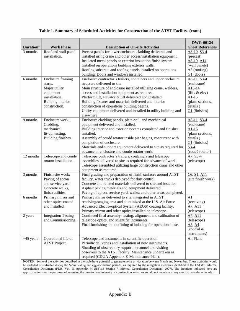
6 Appendix B
Table 1. Summary of Scheduled Activities for Construction of the ATST Facility. (cont.)
Duration1
Work Phase Description of On-site Activities
DWG-00124
Sheet References
3 months Roof and wall panel
installation.
Precast panels for lower enclosure cladding delivered and
installed using crane and other access/installation equipment.
Insulated metal panels or exterior insulation finish system
installed on operations building exterior walls.
Roofing substrate and roofing panels installed on operations
building. Doors and windows installed.
A8-10, S3-4
(precast)
A8-10, A14
(wall panels)
A5 (roofing)
G1 (doors)
6 months Enclosure framing
starts.
Major utility
equipment
installation.
Building interior
construction.
Enclosure contractor’s trailers, containers and upper enclosure
structure delivered to site.
Main structure of enclosure installed utilizing crane, welders,
access and installation equipment as required.
Platform lift, elevator & lift delivered and installed
Building fixtures and materials delivered and interior
construction of operations building begins.
Utility equipment delivered and installed in utility building and
elsewhere.
A8-11, S3-4
(enclosure)
A13-14
(lifts & elev)
A1-15
(plans sections,
details )
G1 (finishes)
9 months Enclosure work:
Cladding,
mechanical
fit-up, testing,
Building finishes.
Enclosure cladding panels, plate-coil, and mechanical
equipment delivered and installed.
Building interior and exterior systems completed and finishes
installed.
Assembly of coudé rotator inside pier begins, concurrent with
completion of enclosure.
Materials and support equipment delivered to site as required for
advance of enclosure and coudé rotator work.
A8-11, S3-4
(enclosure)
A1-15
(plans sections,
details )
G1 (finishes)
S3-4
(coudé rotator)
12 months Telescope and coudé
rotator installation.
Telescope contractor’s trailers, containers and telescope
assemblies delivered to site as required for advance of work.
Telescope assembled utilizing large construction crane and other
equipment as required.
A7, S3-4
(telescope)
3 months Finish site work:
Paving of apron
and service yard.
Concrete walks,
finish utilities.
Final grading and preparation of finish surfaces around ATST
facility, water trucks deployed for dust control.
Concrete and related materials delivered to site and installed
Asphalt paving materials and equipment delivered.
Paving of apron, service yard, walks, and other areas completed.
C6, S1, A11
(site finish work)
6 months Primary mirror and
other optics coated
and installed.
Primary mirror delivered to site, integrated in ATST
receiving/staging area and aluminized at the U.S. Air Force
Advanced Electro-optical System (AEOS) coating facility.
Primary mirror and other optics installed on telescope.
A1
(receiving)
A7, A11
(telescope)
2 years Integration Testing
and Commissioning.
Continued final assemby, testing, alignment and calibration of
telescope optics, and scientific intruments.
Final furnishing and outfitting of building for operational use.
A7, A11
(telescope)
A3, A4
(control &
instruments)
~45 years Operational life of
ATST Project.
Telescope and instuments in scientific operation.
Periodic deliveries and installation of new instruments.
Shuttling of observatory support personnel and visiting
observers to the ATST facility. Maintenance undertaken as
required (CDUA Appendix E-Maintenance Plan).
All Plans
NOTES: 1Some of the activities described in the table have potential to generate noise or vibration between March and November. These activities would
be curtailed or restricted during the ‘u‘au nesting and egg-incubation periods, as required by the mitigation measures identified in the USFWS Informal
Consultation Document (FEIS, Vol. II, Appendix M-USFWS Section 7 Informal Consultation Document, 2007). The durations indicated here are approximations for the purposes of assessing the duration and intensity of construction activities and do not correlate to any specific calendar schedule.
7 Appendix B
2.0 Mobilization, Clearing and Demolition
At the initiation of construction, and periodically during the course of the project, contractors’ trailers,
storage containers, waste receptacles, and equipment would be transported to the site. Other than the
ATST construction site itself, the main area identified for staging these facilities is a portion of the
Federal Aviation Administration (FAA) property as shown in the DWG-00124, sheet C1. Use of this area,
and augmentation with any other ancillary staging areas, would be negotiated with the property owners.
Minimal removal of vegetation would be necessary to clear the site. Existing vegetation is very sparse and
no Federally-threatened ‘ahinahina (Haleakalā silverswords, or Argyroxiphium sandwicense) or other
protected species have been identified on the construction site. Land clearing would be done using
bulldozers and other heavy machinery.
Facilities required to be demolished or removed to clear the site would include:
1. The ATST test tower and its foundations,
2. Tower and weather station belonging to the Institue for Astronomy (IfA),
3. Driveway, parking area, and rock wall borders at the Mees Solar Obsrvatory (MSO) facility,
4. MSO generator and other selective demolition at the MSO shop/utility area; and,
5. MSO facility underground cesspool. (Removal of the cesspool would require testing of the
surrounding soil and possible remediation measures. Proper disposal of the cesspool, treatment of
the soil, and all other aspects of this work would comply with applicable regulations of the
Environmental Proection Agency (EPA) and Hawai’i Department of Health.)
Clearing and demolition work would be staged, beginning with the removal of the test tower and other
on-site structures and continuing later with the cesspool (when the transition can be made to the new
individual wastewater treatment plant) and finally the interior demolition work in the MSO facility after
the ATST structure is nearly complete. The exterior site demolition would require the use of bulldozers,
dump trucks, Bobcat-type excavators, and other heavy machinery.
3.0 Grading/Leveling
The construction of the ATST facility would require the creation of a level pad at least 20 feet wider in all
directions than the base level footprint of the enclosure and the operations building (see DWG-00124
sheet C6 for overall building layout). The critical nature of the structural bearing condition requires that
the level area be achieved primarily by removal of soil and rock rather than by a cut and fill approach.
The initial grade cut at this site would be at approximately 1 foot above the finished grade around the
ATST facility, which is expected to be at the 9,980-foot contour level. This would be done using a
bulldozer, backhoe, jackhammer, dump truck, and other standard heavy equipment. An estimated 2,500
cubic yards of soil and rock would be removed for leveling in order to prepare the site for construction.
Figure 2 (and DWG-00124, sheet C-5) shows the extent of the leveling necessary for the ATST Project.
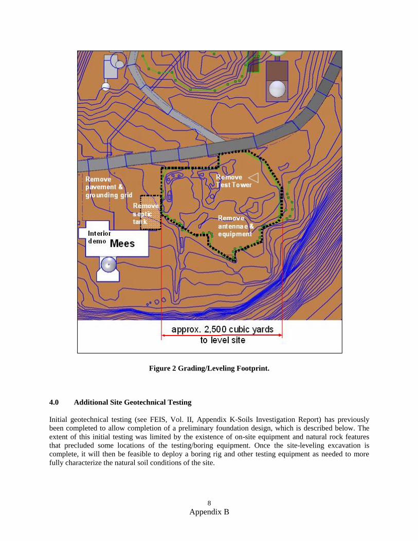
8 Appendix B
Figure 2 Grading/Leveling Footprint.
4.0 Additional Site Geotechnical Testing
Initial geotechnical testing (see FEIS, Vol. II, Appendix K-Soils Investigation Report) has previously
been completed to allow completion of a preliminary foundation design, which is described below. The
extent of this initial testing was limited by the existence of on-site equipment and natural rock features
that precluded some locations of the testing/boring equipment. Once the site-leveling excavation is
complete, it will then be feasible to deploy a boring rig and other testing equipment as needed to more
fully characterize the natural soil conditions of the site.
9 Appendix B
This testing is expected include soil borings down to solid rock (up to 20 feet deep) in critical locations
required to adequately characterize the soil/rock substrate under the telescope and enclosure foundation
(see DWG-00124, sheets C5 and S1). Laboratory testing will be conducted on samples taken from the
site. On-site testing may also include ground penetrating radar and/or downhole-crosshole dynamic
vibration analysis. The results of this additional testing would allow definitive design of the final
excavation and foundation systems for the ATST facility
5.0 Foundation and Utility Excavation, Cesspool Removal
The second phase of excavation would include the removal of rock and soil as required to accommodate
the foundation systems of the telescope pier, the telescope enclosure, the operations building, the elevator
and platform lift, the utility building, and the utility chase. This major structural excavation is expected to
follow the leveling work and the additional site testing. Additional excavation would also be needed in
order to trench for utility lines, all of which would be installed underground. It is estimated that
approximately 2,150 cubic yards of soil would be excavated for construction purposes, for a combined
excavation total of 4,650 cubic yards when added to the 2,500 cubic yards of soil removed during
grading/leveling activities. The majority of this second phase excavation work would be done using
bulldozers, backhoe, trencher, and a hydraulic hammer or jackhammers to break up larger lava sections.
In addition to the general excavation methods, a truck-mounted augur is expected to be deployed for
drilling holes for caissons down to bedrock, as described below in the Section 5.0-Foundation and Utility
Excavation.
The removal of the existing cesspool, which serves the Mees facility, is also expected to be accomplished
during this second phase of excavation and site preparation. The new individual wastewater system (IWS)
(as indicated on DWG-00124, sheets C2 & C5 and described in the FEIS, Vol. I, Section 2.4.4) would be
installed to serve as the long-term wastewater system for ATST and Mees. If the installation of the IWS is
not logistically feasible at this point, a temporary holding tank for catchment of the Mees facility
wastewater may be installed and periodically pumped out until the permanent IWS can be implemeted.
All aspects of the removal of the cesspool and the conversion to the IWS would comply with applicable
regulations of the State of Hawai'i Department of Health.
6.0 Soil Retention or Repair Measures
Some soil retention and fill are likely to be advantageous to provide support for the extended apron
around the base of the enclosure and at other peripheral areas. This retention would be achieved using on-
site native rock to form a sloped rip-rap embankment.
In some places, especially in the area where the existing cesspool is removed, there is an expected
requirement for over-excavation, fill, and re-compaction. In this area, and anywhere else that fill would be
required, every effort would be made to utilize existing on-site soil. Any required importation of outside
fill would comply with sterilization procedures and other required precautions against unintentional
importation of invasive biological species.
7.0 Placement of Excess Soil and Rock
At an average volume of 20 cubic yards per normal truckload, approximately 250 truckloads of rock and
soil would be excavated and relocated. To some extent, especially at the utility excavations, the soil
would be replaced in its original location as backfill. However, a significant percentage of the excavated
material would be displaced by site leveling and foundations. All of this native rock and soil removed
from the site would be placed at locations within HO boundaries under supervision of a Cultural Monitor.
The placement areas, as identified in the FEIS, are shown in DWG-00124 sheet C2. The final
10 Appendix B
determination of appropriate soil placement will be subject to approval by the corresponding land owners
and tenants of adjacent properties.
All soil placement and backfill would be configured to maintain the established stormwater management
flow paths for HO (FEIS, Vol. II, Appendix L-Stormwater Management Plan for HO). For example,
material will be kept clear of the concrete drainage channels. The embankment of the fill material along
the edges of any drainage channels or swales would be stabilized with native rocks sloped at an angle that
would not result in erosion into the drainage paths. The slope of newly placed soil would also be
configured to maintain vehicular access to required areas.
A significant percentage of the material that would be excavated from the site is expected to be in the
form of large intact pieces of rock. Subject to approval by IfA, other HO tenants, and the Cultural
Monitor, these large rocks may be placed at locations around the HO property. As an additional strategy
for beneficial use of on-site soil material, sandy and silty material may be taken from the infiltration basin
area to be utilized for backfill around the ATST structures. This could potentially eliminate the need for
imported backfill material and would also augment periodic removal of finer material that must be done
to maintain the capacity and percolation of the infiltration basin to help reduce potential erosion.
8.0 Concrete Work - Foundations
To determine the extent of work required for the most significant and critical underground support
structures of the ATST facility, a preliminary design for the telescope and enclosure foundations has been
established (see DWG-00124, sheet S1). For The purposes of that design, the bearing capacity of the
natural rock and soil were taken from the preliminary geotechnical report (FEIS, Vol. II-Appendix K)
prepared by Island Geotechnical Engineering, Inc. Based on that report and load conditions stipulated by
the ATST engineering team, M3 Engineering and Technology, Inc., a firm knowledgable in the design of
telescope facilities, was contracted to recommend an appropriate foundation system for the ATST facility.
Figures 3 and 4 are excerpted from the M3 Engineering design. Their recommndation is for a concrete
mat foundation approximately 1 meter thick supported from the solid basalt layer that underlies the site.
Because the basalt layer is sloping, poured concrete caissons (underground columns) extending from
underneath the mat down to the solid basalt layer would be necessary in some locations. A total of
approximately 21 caisssons would be required 1 meter (3 feet 3 inches) in diameter and of lengths varying
from 2 meters (6 feet 6 inches) to a maximum of approximately 6 meters (20 feet). These caissons would
be installed by drilling holes, using a truck-mounted auger, and then pouring concrete into the holes. No
blasting or impact driving of piles would be done. Figure 5 shows the depth and location of the caissons
in relation to the telescope pier, the enclosure, and the natural rock layer of the site. In addition to this
caisson/mat system, ATST foundations would include relatively shallow (less than 3 ft. deep) pad and
linear footings for the building columns and walls.
9.0 Concrete Work – Walls and other Above-ground Structures
The walls of the ATST telescope pier are to be formed of cast-in-place reinforced concrete, as depicted in
the illustrations below and DWG-00124, sheet S3. The construction of formwork for these walls will be
an extensive construction task requiring a large crane, scaffoldings and lifts, hand/power tools for
assembly and a crew of carpenters. Reinforcing steel will be placed prior to erection of each section of
formwork, and the concrete for the telescope pier walls will be pumped or lifted in a crane-mounted
bucket for placement in the forms. Similar placement of cast-in-place concrete is also expected to be
utilized for other above-ground structures such as elevated floor slabs and retaining walls.
Precast concrete panels are proposed for exterior cladding of the lower enclosure as depicted on DWG-
00124, sheets S3-4 & A8-10. These panels are expected to be fabricated at an off-site location and
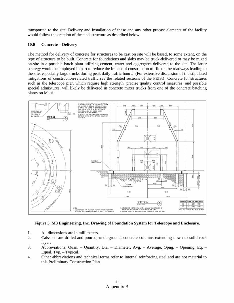
11 Appendix B
transported to the site. Delivery and installation of these and any other precast elements of the facility
would follow the erection of the steel structure as described below.
10.0 Concrete – Delivery
The method for delivery of concrete for structures to be cast on site will be based, to some extent, on the
type of structure to be built. Concrete for foundations and slabs may be truck-delivered or may be mixed
on-site in a portable batch plant utilizing cement, water and aggregates delivered to the site. The latter
strategy would be employed in part to reduce the impact of construction traffic on the roadways leading to
the site, especially large trucks during peak daily traffic hours. (For extensive discussion of the stipulated
mitigations of construction-related traffic see the related sections of the FEIS.) Concrete for structures
such as the telescope pier, which require high strength, precise quality control measures, and possible
special admixtures, will likely be delivered in concrete mixer trucks from one of the concrete batching
plants on Maui.
Figure 3. M3 Engineering, Inc. Drawing of Foundation System for Telescope and Enclosure.
1. All dimensions are in millimeters.
2. Caissons are drilled-and-poured, underground, concrete columns extending down to solid rock
layer.
3. Abbreviations: Quan. – Quantity, Dia. – Diameter, Avg. – Average, Opng. – Opening, Eq. –
Equal, Typ. – Typical.
4. Other abbreviations and technical terms refer to internal reinforcing steel and are not material to
this Preliminary Construction Plan.
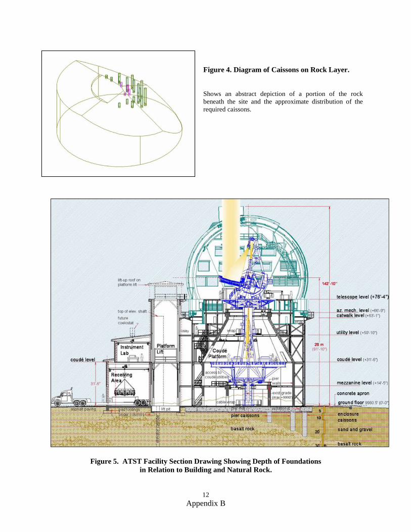
12 Appendix B
Figure 4. Diagram of Caissons on Rock Layer.
Shows an abstract depiction of a portion of the rock
beneath the site and the approximate distribution of the
required caissons.
Figure 5. ATST Facility Section Drawing Showing Depth of Foundations
in Relation to Building and Natural Rock.
13 Appendix B
11.0 Structural Steel
Following the installation of foundation systems and other cast-in-place concrete structures the structural
steel elements of the ATST facility will be installed (see DWG-00124, sheet S2). The columns, beams,
bracing, railings, stairs and other complex elements would be fabricated at an off-site shop and
transported to the site. Erection on-site would require a large construction crane, welding equipment,
hand/power tools for assembly as well as scaffoldings lifts and other temporry access equipment.
The lower enclosure and the operations building are multi-level custom-designed steel structures. The
utility building is to be a pre-engineered steel structure manufactured by a standard metal building
fabricator. .As indicated in Table 1, the utility building is expected to be built as early as possible in the
overall construction sequence to allow for its use as a protected and sound-contained facility for
construction assembly tasks.
All of these structures will be designed to withstand the gravity and lateral loads as defined below in
Section 21.0-Structural Criteria.
12.0 Cladding, Roofing and Weatherproofing
The exterior walls of the lower enclosure will be clad in precast concrete panels, as previously noted. The
roof of the lower enclosure will be formed by the rotating, upper enclosure as described below. The walls
of the operations building will be insulated metal panels or exterior insulation finish system. The roof of
the operations building as well as the roof and exterior walls of the utility building will be constructed of
a pre-manufactured metal panel system. All of these exterior wall materials and a preliminary set of
details for their installation are depicted on the building elevations (DWG-00124, sheets A8 to A13).
Insulation, seals, doors and windows installed in the exterior walls of the ATST facility would be as
depicted in DWG-00124 floor plan, elevations and schedules. All of these materials would be fabricated
off-site and delivered to the site for installation during the exterior wall/roof construction phase of the
project.
Installation of the exterior walls, roofs and associated materials would require a crane, lifting and access
equipment, standard power/hand tools, and specialized work crews for the various materials being
iintalled.
13.0 Interior Construction
Following the completion of exterior walls and roof, the interior build-out of the ATST facility would
begin. This would include interior partitioning, doors, ceiling systems, finishes and built-in equipment as
shown on the DWG-00124 floor plans and schedules. This work would be coordinated and
contemporaneous with the installation of interior mechanical and electrical equipment as described below.
This phase of the project would overlap with the construction of the enclosure and continue until the final
completion of the facility construction project.
Installation of the interior building systems would require lifting and access equipment, standard
power/hand tools, and specialized work crews for the various materials being installed.
14.0 Mechanical and Electrical Equipment
Mechanical equipment for the ATST facility includes heating ventilation and air-conditioneing (HVAC)
equipment, facility cranes, elvators, and a large platform lift. Electrical equipment includes primary
14 Appendix B
switchgear and transformer; a diesel generator and transfer switch; power and energy management
system; motor controls; distribution panels; circuit protection devices, outlets, switches and lighting.
Preliminary specification of this mechanical and electrical equipment is decribed in DWG-00124 sheets
A15, U1-3 & G30. Specification data is described below in Section 13.0-Mechanical Criteria and
Electrical Criteria. Specific manufacturers and models will be subject to final specification and
competitive procurement. All of this equipment will be specified and installed in compliance with
applicable State of Hawai’i codes and regulations.
Mechanical and electrical equipment will be factory fabricated and will arrive at the site in the largest
feasible components for on-site installation. Piping, ducting and conduit runs will be largely assembled
and installed on site. Installation and interconnection of equipment will require a crane, access equipment,
welding and pipe-fitting equipment, standard hand/power tools and specialized work crews.
15.0 Construction of Complex Mechanical Structures - Telescope and Enclosure
The support structures for the telescope and enclosure (the pier and the lower enclosure) will be
completed as part of the fixed building construction described above. Following completion of the lower
enclosure, installation of the (upper, rotating) enclosure will begin. The work will commence with
installation and alignment of the enclosure azimuth track. Following this, the large steel structural framing
will be erected, including the ring beam, arch girders, and all secondary bracing and support members.
Azimuth support bogies will also be installed and shimmed/braced in place. The up-and-over shutter
assemblies will then be framed and installed on the carousel structure. Following this, cladding and
insulation will be installed to make the enclosure weather tight. At this point, mechanical equipment, such
as azimuth drive bogies, shutter drives, interior cranes and platforms and other subsystems will be
installed and tested. The enclosure control system will then be installed, along with the local interlock
controllers, and final enclosure acceptance testing carried out.
The installation of the Telescope Mount Assembly (TMA) will begin in parallel with construction of the
enclosure. Specifically, the coudé rotator assembly components will be pre-positioned inside of the
telescope pier, with a safety cap installed on top of the pier. This will allow work on the coudé rotator to
continue inside of the pier whilst enclosure construction (above) begins. This coudé rotator work will
commence with installation and alignment of the coudé rotator azimuth track assembly. The coudé rotator
structure will then be installed, followed by flooring, thermal systems, and coudé drives and other
mechanical subsystems.
For safety reasons, the remainder of the TMA site construction will not commence until the enclosure
construction is complete. Once this enclosure milestone is reached, the mount azimuth track assembly
will be installed and aligned inside the enclosure. Following this, the mount structure will be installed,
bearings and drives installed and aligned, and all other mechanical equipment added. Mass balance of the
telescope will then begin, followed by installation and test of the mount control system and interlocks.
Once the TMA assembly is complete, the formal start of Integration, Test, and Commissioning (IT&C)
will begin. (IT&C includes the installation of the optics assemblies, wavefront control system,
instrumentation, high-level software, and other scientific equipment inside the observatory). In parallel
with the start of IT&C will be the installation and test of the enclosure thermal systems, including the
exterior plate coil system, piping and plumbing, and thermal control systems. Other mechanical systems,
such as coudé environmental control, chillers, and related equipment will also be installed and tested at
this point.
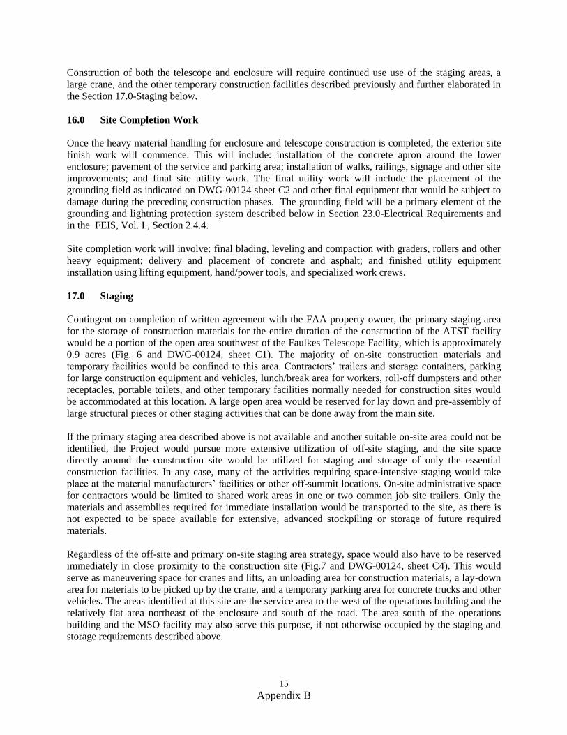
15 Appendix B
Construction of both the telescope and enclosure will require continued use use of the staging areas, a
large crane, and the other temporary construction facilities described previously and further elaborated in
the Section 17.0-Staging below.
16.0 Site Completion Work
Once the heavy material handling for enclosure and telescope construction is completed, the exterior site
finish work will commence. This will include: installation of the concrete apron around the lower
enclosure; pavement of the service and parking area; installation of walks, railings, signage and other site
improvements; and final site utility work. The final utility work will include the placement of the
grounding field as indicated on DWG-00124 sheet C2 and other final equipment that would be subject to
damage during the preceding construction phases. The grounding field will be a primary element of the
grounding and lightning protection system described below in Section 23.0-Electrical Requirements and
in the FEIS, Vol. I., Section 2.4.4.
Site completion work will involve: final blading, leveling and compaction with graders, rollers and other
heavy equipment; delivery and placement of concrete and asphalt; and finished utility equipment
installation using lifting equipment, hand/power tools, and specialized work crews.
17.0 Staging
Contingent on completion of written agreement with the FAA property owner, the primary staging area
for the storage of construction materials for the entire duration of the construction of the ATST facility
would be a portion of the open area southwest of the Faulkes Telescope Facility, which is approximately
0.9 acres (Fig. 6 and DWG-00124, sheet C1). The majority of on-site construction materials and
temporary facilities would be confined to this area. Contractors’ trailers and storage containers, parking
for large construction equipment and vehicles, lunch/break area for workers, roll-off dumpsters and other
receptacles, portable toilets, and other temporary facilities normally needed for construction sites would
be accommodated at this location. A large open area would be reserved for lay down and pre-assembly of
large structural pieces or other staging activities that can be done away from the main site.
If the primary staging area described above is not available and another suitable on-site area could not be
identified, the Project would pursue more extensive utilization of off-site staging, and the site space
directly around the construction site would be utilized for staging and storage of only the essential
construction facilities. In any case, many of the activities requiring space-intensive staging would take
place at the material manufacturers’ facilities or other off-summit locations. On-site administrative space
for contractors would be limited to shared work areas in one or two common job site trailers. Only the
materials and assemblies required for immediate installation would be transported to the site, as there is
not expected to be space available for extensive, advanced stockpiling or storage of future required
materials.
Regardless of the off-site and primary on-site staging area strategy, space would also have to be reserved
immediately in close proximity to the construction site (Fig.7 and DWG-00124, sheet C4). This would
serve as maneuvering space for cranes and lifts, an unloading area for construction materials, a lay-down
area for materials to be picked up by the crane, and a temporary parking area for concrete trucks and other
vehicles. The areas identified at this site are the service area to the west of the operations building and the
relatively flat area northeast of the enclosure and south of the road. The area south of the operations
building and the MSO facility may also serve this purpose, if not otherwise occupied by the staging and
storage requirements described above.
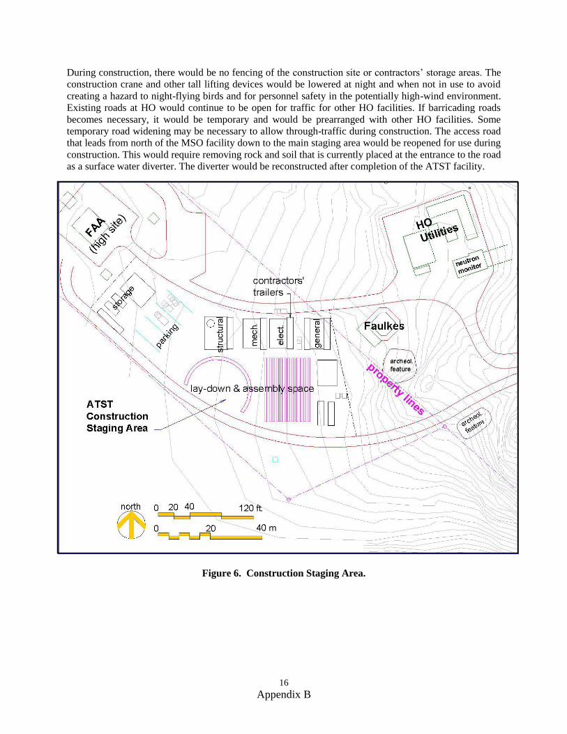
16 Appendix B
During construction, there would be no fencing of the construction site or contractors’ storage areas. The
construction crane and other tall lifting devices would be lowered at night and when not in use to avoid
creating a hazard to night-flying birds and for personnel safety in the potentially high-wind environment.
Existing roads at HO would continue to be open for traffic for other HO facilities. If barricading roads
becomes necessary, it would be temporary and would be prearranged with other HO facilities. Some
temporary road widening may be necessary to allow through-traffic during construction. The access road
that leads from north of the MSO facility down to the main staging area would be reopened for use during
construction. This would require removing rock and soil that is currently placed at the entrance to the road
as a surface water diverter. The diverter would be reconstructed after completion of the ATST facility.
Figure 6. Construction Staging Area.
17 Appendix B
Figure 7. Staging Area in Close Proximity to Construction Site.
18.0 Construction Traffic
The extent of traffic required for construction of the ATST facility has been extensively examined as part
of the Federal environmetal permitting process. This analysis, conducted in cooperation with
theHaleakalā National Park (HALE) and the Federal Highways Administration (FHWA), is fully
documented in the FEIS.
The total number of truck and automobile trips anticipated to be required over the 7-year construction,
integration and commissioning phases of the ATST Project is approximately 25,000, as listed and
described in the FEIS, Vol. I, Table 2-4. Less than 800 of these anticipated vehicle-trips are by large
trucks (FHWA class 5 and larger). The majority of the anticipated trips are by small pick-up trucks, vans
and passenger vehicles as required for the commuting of workers, small equipment or material deliveries,
and passenger car traffic for inspection and supervision. During all phases of the ATST Project,
carpooling by workers to the summit would be mandated, to the maximum extent practicable, in order to
minimize traffic impacts and to address parking space limitations on the site.
Following the defined five-year construction phase of the ATST Project, the integration, testing and
commissioning phase would extend for approximately two years, during which the anticipated traffic on
the Park road would be limited to approximately 4 passenger vehicles per day, 4 pick-up trucks or vans
per day and 2 truck deliveries per week. Following that, and extending for the operational life of the
18 Appendix B
project, the ATST-related use of the roads leading to the site would be approximately 3 roundtrips for a
van shuttle per day, 3 roundtrips for passenger vehicles per day, 1 truck-trip per month for delivery of
domestic water, liquid nitrogen, or diesel fuel for the generator, and 3 truck trips per year for occasional
transportation of scientific instruments. Traffic during these phases is also included in the FEIS, Vol. I,
Table 2-4.
19.0 Basis of Design
The criteria used to develop the current preliminary design and for further development into construction
documents are fully described in CDUA Appendix D-ATST SPEC-0032 Design Requirements for the
ATST Support Facilites.
20.0 Regulatory Criteria
All aspects of the ATST facility are to comply with the following codes:
1. International Building Code, 2006 edition
2. Code of Federal Regulations 10 CFR Parts 433 & 434
a. Energy Efficiency Standards for Design and Construction of New Federal Commercial
and High-Rise Residential Buildings (433)
b. Energy Code for New Federal Commercial & High-Rise Residential Buildings (434)
3. International Energy Efficiency Code (IEEC) , 2006 edition; applicable provisions of IEEC in
coordination with the above CFR standards
4. International Mechanical Code, 2006 edition
5. International Plumbing Code, 2006 edition
6. National Electric Code, 2005 edition
7. Occupational Safety and Health Act (OSHA)
8. American Concrete Institute (ACI) 301, 318 and other applicable specifications
9. American Institute of Steel Construction (AISC) - Structural Steel for Buildings
10. American Welding Society (AWS) D1.1-92 - Structural Welding Code – Steel
11. American Society for Testing and Materials (ASTM) (various applicable standards)
12. American Society of Mechanical Engineers (ASME) A17.1 Elevator and Escalator Code
(Personnel Elevator & LU/LA Lift)
13. ASME B20.1 Safety Standard for Conveyors and Related Equipment (Platform Lift)
14. The Americans with Disabilities Act Accessibility Guidelines (ADAAG)
15. Uniform Federal Accessibility Standards (UFAS)
16. Materials and methods specifications as stipulated by Maui Electric Co., Inc. (MECO)
17. Specifications of Hawaiian Telecom, and other utility authorities
18. Manufacturer’s specifications and trade standards for all materials and equipment
19. Hawai‘i Department of Health standards for wastewater processing and disposal
19 Appendix B
20. Haleakalā High Altitude Observatory (HO) Long Range Development Plan (LRDP)
21. Final Environmental Impact Statement (FEIS) for the ATST Facility at HO, including all
stipulated mitigations and conditions
21.0 Structural Criteria
For design of the foundation systems and other structural elements of the ATST facility, the following
structural criteria have been determined:
1. Lateral force design (wind and seismic), at a minimum, will comply with the load criteria dictated
by the 2006 International Building Code and its associated companion codes. (This set of codes
provides for a more conservative site-specific approach to lateral seismic loads than is dictated
by the 1997 Uniform Building Code, currently adopted by Maui County).
2. Seismic design of all elements of the ATST facility is a critical concern. The telescope pier will
be designed using finite element analysis to assure compliance with stiffness and survivability
requirements.
3. The ATST telescope and instruments will be extremely sensitive to any impacts or vibrations
induced on the structures that directly or indirectly support them. All possible strategies will
employed to isolate the building foundations and structure from the telescope pier or other
potential paths of vibration transmission. Specifications and mounting conditions for facility
equipment shall be designed to minimize potential induced vibration.
4. Floor loading throughout the ATST facility of at least 100 pounds per square foot and higher in
some locations based on special loading conditions.
5. The foundations of the ATST facility will be sized to support and carry all operational and
survival loads. In particular, long-term creep and/or settling of the pier foundation shall be strictly
minimized, as this can impact performance of the telescope. All foundation systems of the ATST
facility will be designed to be compatible with the soil properties expected at the site, as
characterized by the preliminary Island Geotechnical Soils Report (see FEIS, Vol. II, Appendix
K-Soils Investigation Report) and future testing.
22.0 Mechanical Criteria
1. The heating ventilation and air-conditioning (HVAC) requirements for the ATST facility will be
based on the climatic conditions of the site and the requirements described in the SPEC-0032 for
each of the building spaces. In general, the HVAC system will be as normally provided for
typical office, laboratory, shop and other functional areas.
2. The primary means for cooling and heating the building spaces in the operations building is a heat
pump and air handler system. The total capacity of the system is expected to be approximately 10
tons (120,000 BTU/h). Other alternatives to this system may be considered for better economy or
more refined control.
3. A special concern for the ATST facility will be the prevention of undesirable migration of heated
air from sources in the building to the coudé lab and telescope levels of the enclosure. Creating
negative relative pressure in air spaces adjacent to those areas, effective door seals in vestibules,
physical barriers to the passage of air in concealed spaces and other strategies will be employed.
20 Appendix B
4. The coudé lab inside the pier will be conditioned by a dedicated clean-room-type HVAC system.
5. The lower enclosure will be actively ventilated by fans at two locations between the ground level
of the lower enclosure and the operations building, as shown in DWG-00124 sheet A1. The
ventilation air will be exhausted through actively controlled louver panels in the walls of the
operations building.
6. The surface of the upper rotating enclosure will be actively cooled with a liquid cooling system.
That system will include provision for supply and return piping runs; building space for chillers
and other equipment; power for chillers and pumps; spill containment and other elements.
Specific requirements for this system will be further developed as part of the full enclosure design
process.
7. An integrated system for control of the facility HVAC equipment will be provided as part the
ATST support facility.
23.0 Electrical Criteria
1. The design of the ATST facility provides adequate electrical power for all observatory systems.
The primary source for this power will be the HO substation of Maui Electric Co. (MECO). A
back-up generator with automatic transfer switch will be included in the design. The anticipated
electrical loads for equipment will be further refined as part of the final construction documents.
Appropriate switchgear, over current protection, distribution systems, and other elements of the
electrical system will be included. The preliminary schedule for the peak electrical demand for
the ATST facility is included below:
a. Lights and general use outlets 50 kVA
b. Chiller, pumps and air-handling units 160
c. Fans for Lower Enclosure and utility bldg. 100
d. Lifting devices 160
e. Instrument utilities 50
f. Enclosure mechanisms 80
g. Telescope mount and hydrostatic bearings 90
h. Computer control hardware 15
i. Instruments and rotating platform 60
j. Mirror mechanisms and thermal control 15
k. Mirror coating facility 50
TOTAL 830 kVA
2. The distribution system will include provision for all required voltage levels and include a
separate wiring system for Uninterruptible Power Supply (UPS) protected circuits for critical
equipment. An approximation of the different levels and types of power required in the
individual building spaces is provided in DWG-00124 and in the ATST Interconnects and
Services document.
21 Appendix B
3. A power and energy management system (PEMS) will be included in the design of the electrical
system. A primary objective of the PEMS will be to maintain the peak power utilization of the
facility below a MECO-established threshold to keep the utility rate paid by ATST in the lowest
possible bracket. A power monitoring unit and a programmable logic controller will be located
near the main electrical switchgear in the utility building (see DWG-00124, sheet A15).
4. The design of the ATST facility electrical system will minimize electromagnetic interference with
scientific instruments and other telescope systems.
5. A special concern for the entire ATST observatory electrical system is achieving an effective
earth ground for protection of equipment and personnel against lightning. Based on preliminary
consultation, this is expected to be an earth electrode system, composed of a set of conductors in
shallow trenches filled with conductive concrete. (see DWG-00124, sheet C2) The concrete and
conductors would be kept moist by water, gravity-fed through perforated pipe that runs the extent
of the trenches and is embedded with the conductors. The entire system, including surge-
suppression devices and cad-welded connection to the steel structure of the buildings, will be
specified by the grounding and lightning-protection consultant.
6. Data and control cabling, low voltage wiring, and other specialized observatory systems will be
included as required. Final requirements for fire alarm system, an electronic card access system
and other special building-related systems will be developed as part of the final construction
documents.
24.0 Best Management Practices
A variety of best management practices (BMPs) (required practices established in the Management Plan
and policies reflecting public consultation during the EIS process) would be implemented during
construction to prevent damage to the natural environment. These BMPs would include the following:
1. Implementation of the Stormwater Management Plan (SWMP), specific to HO, which is
included in the FEIS as Appendix L. This would include all BMPs in Sections 3.1 and 3.2 of
Appendix L for recommended construction practices and stormwater control.
2. During construction, temporary diverters and hard surfaces would be utilized to direct surface
water flow to the existing stormwater drainage system. As soon as possible, permanent gutters
and leaders would be installed on the buildings to capture rainwater and direct it to the
underground cistern.
3. Portable toilets with containment tanks would be utilized during early construction work. As
soon as possible, a permanent wastewater treatment facility would be installed, which uses
aeration and biologically accelerated treatment techniques that achieve effluent standards
acceptable for infiltration back to groundwater.
4. Cultural resources monitoring during all leveling and excavation activities in order to prevent
damage to undiscovered cultural resources.
5. Using native soils to fill holes upon completion of construction, and replanting grounding
trenches, other excavated areas, and soil deposition areas with native vegetation to prevent
erosion.
22 Appendix B
6. Scheduling deliveries of concrete and other materials at times that minimize conflict with tourist
traffic on the Park road to Haleakalā.
7. Using signage at the project site and along the roadways to ensure vehicle, pedestrian, and
bicycle safety during construction.
8. Dust control would be done by watering the disturbed ground using non-potable water trucked to
the site by the contractor specifically for that purpose. Potable water would not be used for dust
control.
23 Appendix B
25.0 Acronyms
‘ahinahina Haleakalā silverswords, or Argyroxiphium sandwicense
ACI American Concrete Institute
ADAAG Americans with Disabilities Act Accessibility Guidelines
AEOS U.S. Air Force Advanced Electro-optical System
AISC American Institute of Steel Construction
ASME American Society of Mechanical Engineers
ASTM American Society for Testing and Materials
ATST Advanced Technology Solar Telescope
AWD American Welding Society
BTU/h British thermal units per hour
CDUA Conservation District Use Application
DWG drawing
EPA Environmental Proection Agency
FAA Federal Aviation Administration
FEIS Final Environmental Impact Statement
FHWA Federal Highways Administration
HALE Haleakalā National Park
HO Haleakalā High Altitude Observatory
HVAC heating ventilation and air-conditioning
IEEC International Energy Efficiency Code
IfA Institute for Astronomy
IT&C Integration, Test, and Commissioning
IWS Individual Wastewater System
kVA kilovolt-ampere
LRDP Long Range Development Plan
MECO Maui Electric Co., Inc.
MSO Mees Solar Obsrvatory
OSHA Occupational Safety and Health Act
PEMS power and energy management system
SWMP Sotrmwater Management Plan
TMA Telescope Mount Assembly
UFAS Uniform Federal Accessibility Standards
UPS Uninterruptible Power Supply

24 Appendix B
THIS PAGE INTENTIONALLY LEFT BLANK
APPENDIX C
SUPPORT FACILITIES
DESIGN REQUIREMENTS DOCUMENT
for the
Advanced Technology Solar Telescope
Haleakalā High Altitude Observatory Site
Haleakalā, Maui, HI
Project Documentation SPEC-0032
Draft 4
Advanced Technology Solar Telescope 950 N. Cherry Avenue Tucson, AZ 85719 Phone 520-318-8102 [email protected] http://atst.nso.edu Fax 520-318-8500
Appendix C
THIS PAGE INTENTIONALLY LEFT BLANK
Project Documentation SPEC-0032
Draft 4
Advanced Technology Solar Telescope 950 N. Cherry Avenue Tucson, AZ 85719 Phone 520-318-8102 [email protected] http://atst.nso.edu Fax 520-318-8500
Appendix C
Support Facilities Design Requirements Document
Jeff Barr July 14, 2009
Support Facilities Design Requirements Document
SPEC-0032 Draft 3 Page ii
Appendix C
REVISION SUMMARY:
1. Date: January 6, 2006 Revision: Initial Draft Changes: Draft used at January 2006 SDR.
2. Date: September 11, 2006 Revision: Draft 2 Changes: Draft used at October 2006 PDR.
3. Date: October 7, 2008 Revision: Draft 3 Changes: Updated for November 2008 SDR
4. Date: June 29, 2009 Revision: Draft 4 Changes: Revisions from SDR, FDR and ATST team comments
5. Date: July 14,2009 Revision: 5 Changes: Finalized for A&E RFP
Support Facilities Design Requirements Document
SPEC-0032 Draft 3 Page iii
Appendix C
TABLE OF CONTENTS
1. REQUIREMENTS OVERVIEW ......................................................................................... 1
1.1 SCOPE AND PURPOSE OF THIS DOCUMENT ......................................................................... 1 1.2 RELATED DOCUMENTS ...................................................................................................... 1
1.2.1 Related ATST Project Documents ............................................................................. 1 1.2.2 Interface Control Documents .................................................................................... 2
2. SUPPORT FACILITIES DEFINITIONS ........................................................................... 2
2.1 SITE INFRASTRUCTURE ...................................................................................................... 2 2.1.1 Demolition & Clearing: ............................................................................................ 2
2.1.2 Major Earthwork: ..................................................................................................... 2 2.1.3 Roads & Driveways: ................................................................................................. 2
2.1.4 Site Utilities: ............................................................................................................. 2
2.2 BUILDINGS ........................................................................................................................ 3 2.2.1 Support & Operations (S&O) Building: ................................................................... 3 2.2.2 Utility Building: ........................................................................................................ 5
2.2.3 Mees Building Modifications (N.I.C): ...................................................................... 5 2.3 HANDLING EQUIPMENT ..................................................................................................... 5
2.3.1 Platform Lift: ............................................................................................................ 5 2.3.2 Personnel Access Equipment: ................................................................................... 5 2.3.3 Cranes: ...................................................................................................................... 5
2.3.4 Articulating-Boom Lifts: ........................................................................................... 5
3. DESIGN REQUIREMENTS ................................................................................................ 6
3.1 ADHERENCE TO SCHEMATIC DESIGN AND APPLICABLE REGULATIONS ............................ 6 3.2 SITE ................................................................................................................................... 6
3.3 SITE INFRASTRUCTURE ...................................................................................................... 6 3.3.1 Demolition and Clearing .......................................................................................... 6 3.3.2 Major Earthwork ...................................................................................................... 7
3.3.3 Roads & Driveways .................................................................................................. 8 3.3.4 Site Utilities ............................................................................................................... 8
3.4 BUILDINGS ...................................................................................................................... 10 3.4.1 Overview ................................................................................................................. 10 3.4.2 Telescope Pier ......................................................................................................... 10
3.4.3 Lower Enclosure ..................................................................................................... 12
3.4.4 Operations Building ................................................................................................ 14 3.4.5 Utility Building........................................................................................................ 19
3.5 HANDLING EQUIPMENT ................................................................................................... 19
3.5.1 Platform Lift ............................................................................................................ 20 3.5.2 Operations Building Elevator ................................................................................. 20 3.5.3 Limited-Use Limited-Application (LU/LA) Lift ...................................................... 21 3.5.4 Facility Cranes........................................................................................................ 21 3.5.5 Articulating Boom Lifts ........................................................................................... 23
Support Facilities Design Requirements Document
SPEC-0032 Draft 3 Page iv
Appendix C
4. GENERAL AND TECHNICAL REQUIREMENTS ....................................................... 24
4.1 OVERALL DESIGN OBJECTIVES ....................................................................................... 24 4.1.1 Minimize Thermal Turbulence ................................................................................ 24 4.1.2 Efficiency, Standardization, and Simplicity ............................................................ 24
4.1.3 Reliability & Durability .......................................................................................... 24 4.1.4 Provision for Maintenance ..................................................................................... 25 4.1.5 Adaptability ............................................................................................................. 25
4.2 APPLICABLE CODES, REGULATIONS, & STANDARDS ....................................................... 25 4.3 GENERAL SITE AND CLIMATIC CONDITIONS.................................................................... 26
4.4 STRUCTURAL DESIGN REQUIREMENTS ............................................................................ 27 4.5 MECHANICAL HVAC REQUIREMENTS ............................................................................ 27 4.6 ELECTRICAL DESIGN REQUIREMENTS ............................................................................. 28
5. SAFETY REQUIREMENTS.............................................................................................. 30
6. DRAWINGS & SPECIFICATIONS ................................................................................. 30
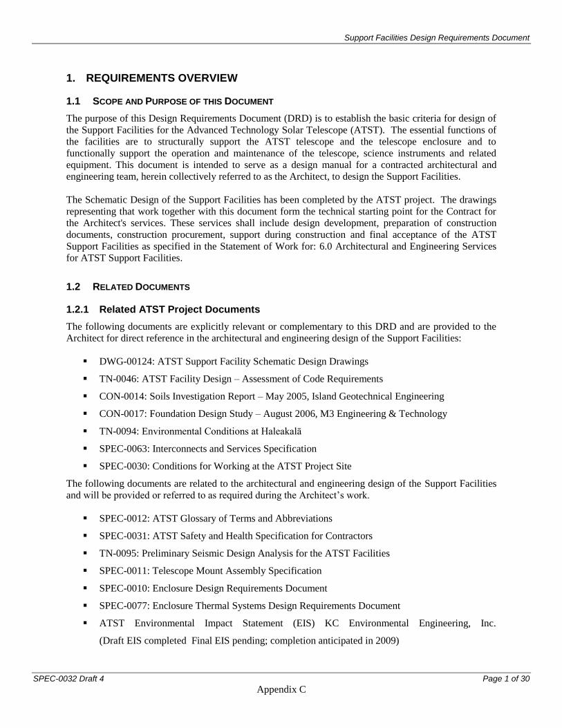
Support Facilities Design Requirements Document
SPEC-0032 Draft 4 Page 1 of 30
Appendix C
1. REQUIREMENTS OVERVIEW
1.1 SCOPE AND PURPOSE OF THIS DOCUMENT
The purpose of this Design Requirements Document (DRD) is to establish the basic criteria for design of
the Support Facilities for the Advanced Technology Solar Telescope (ATST). The essential functions of
the facilities are to structurally support the ATST telescope and the telescope enclosure and to
functionally support the operation and maintenance of the telescope, science instruments and related
equipment. This document is intended to serve as a design manual for a contracted architectural and
engineering team, herein collectively referred to as the Architect, to design the Support Facilities.
The Schematic Design of the Support Facilities has been completed by the ATST project. The drawings
representing that work together with this document form the technical starting point for the Contract for
the Architect's services. These services shall include design development, preparation of construction
documents, construction procurement, support during construction and final acceptance of the ATST
Support Facilities as specified in the Statement of Work for: 6.0 Architectural and Engineering Services
for ATST Support Facilities.
1.2 RELATED DOCUMENTS
1.2.1 Related ATST Project Documents
The following documents are explicitly relevant or complementary to this DRD and are provided to the
Architect for direct reference in the architectural and engineering design of the Support Facilities:
DWG-00124: ATST Support Facility Schematic Design Drawings
TN-0046: ATST Facility Design – Assessment of Code Requirements
CON-0014: Soils Investigation Report – May 2005, Island Geotechnical Engineering
CON-0017: Foundation Design Study – August 2006, M3 Engineering & Technology
TN-0094: Environmental Conditions at Haleakalā
SPEC-0063: Interconnects and Services Specification
SPEC-0030: Conditions for Working at the ATST Project Site
The following documents are related to the architectural and engineering design of the Support Facilities
and will be provided or referred to as required during the Architect’s work.
SPEC-0012: ATST Glossary of Terms and Abbreviations
SPEC-0031: ATST Safety and Health Specification for Contractors
TN-0095: Preliminary Seismic Design Analysis for the ATST Facilities
SPEC-0011: Telescope Mount Assembly Specification
SPEC-0010: Enclosure Design Requirements Document
SPEC-0077: Enclosure Thermal Systems Design Requirements Document
ATST Environmental Impact Statement (EIS) KC Environmental Engineering, Inc.
(Draft EIS completed Final EIS pending; completion anticipated in 2009)
Support Facilities Design Requirements Document
SPEC-0032 Draft 4 Page 2 of 30
Appendix C
Haleakalā High Altitude Observatory Long Range Development Plan
SPEC-0035: ATST Hazardous Material and Hazardous Waste Management Program
CON-0010: Energy Efficiency Design Assistance Study
1.2.2 Interface Control Documents
It is the intent of the ATST project to integrate the design and development of the Support Facilities with
other major ATST subsystem engineering efforts, such as the design of the upper (rotating) enclosure, the
telescope Pier, telescope/instrument utilities, and control systems. Contractor shall coordinate with ATST
project personnel and outside vendors that are designing these related subsystems.
The Support Facilities shall interface with other major ATST project elements as described in the
following Interface Control Documents, which are provided to the Architect along with this DRD:
ICD-1.1/6.2 Telescope Mount Assembly-to-Buildings
ICD-3.1/6.2 Coudé Environmental Systems-to-Buildings
ICD-5.0/6.2 Enclosure-to-Buildings
ICD-5.0/6.5 Enclosure-to-Handling Equipment
2. SUPPORT FACILITIES DEFINITIONS
The Support Facilities consist of: Site Infrastructure, Buildings, and Handling Equipment, which are
defined as follows:
2.1 SITE INFRASTRUCTURE
2.1.1 Demolition & Clearing:
Removal of the existing structures and utilities in the site area where the telescope enclosure and
related Support Facilities are to be constructed.
2.1.2 Major Earthwork:
Excavation as required to provide level platforms for the Support Facilities and to prepare for
foundation installation and forming.
2.1.3 Roads & Driveways:
Provision of exterior access ways, including a paved service yard.
2.1.4 Site Utilities:
Provision of exterior main utility lines and fixtures, including main electrical service, raceways
for telephone and data connection lines, site drainage, water collection system, wastewater
treatment system, and an underground utility chase between the S&O Building and the Utility
Building.
Also included in site infrastructure but not included in the scope of this document are the following:
Site Permits
Environmental Impact Statement
Geotechnical Testing
Support Facilities Design Requirements Document
SPEC-0032 Draft 4 Page 3 of 30
Appendix C
Construction Infrastructure
Although the specification, definition and provision of these elements are not included in the scope of this
professional services contract, applicable aspects of these processes and documents shall be incorporated
into the design of the Support Facilities.
2.2 BUILDINGS
2.2.1 Support & Operations (S&O) Building:
The supporting pier for the telescope (Pier); the lower, non-rotating portion of the telescope enclosure
(Lower Enclosure), and the multi-story structure directly attached to the Lower Enclosure that houses the
control room and other ancillary support spaces (Operations Building) are all included as constituent parts
of a contiguous structure referred to as the Support & Operations (S&O) Building. General descriptions
of these major elements are as follows:
The Pier is a poured-in-place concrete structure, the essential function of which is to provide stable
support for the telescope at the height required to achieve the science objectives of the project. As
such, the structural stiffness and vibration isolation of the Pier are critical parameters. Further
information regarding these criteria will be provided to the Architect by the Telescope Mount
Assembly (TMA) vendor. In addition to the telescope, the Pier also supports a rotating coudé
instrument platform which is housed within the interior volume of the Pier. Detailed information
regarding the dynamic loads of the telescope and the coudé platform will be provided to the Architect
by AURA. The specific interface between the structural design of the Pier and the mechanical and
structural design of the telescope and coudé platform is addressed in the TMA to Buildings Interface
Control Document, and will be the subject of an information exchange as defined and scheduled in
the TMA Contract Statement of Work.
The Lower Enclosure is a steel frame structure, the essential function of which is to support the
Enclosure which rotates with and protects the telescope while providing the observing aperture. The
protection of the telescope from wind, heat, precipitation and other potentially deleterious
environmental conditions is a major factor in the design of both the upper and the lower enclosures.
Notable requirements in this regard for the Lower Enclosure include vibration isolation from the
structure of the Pier and telescope floors as well as incorporation of passive and active thermal
stabilization measures. The specific interface between the Lower Enclosure and the mechanical and
structural design of the upper rotating enclosure is addressed in the Enclosure-to-S&O Building
Interface Control Document, and will be the subject of an information exchange as defined and
scheduled in the Enclosure Contract Statement of Work.
The Operations Building is a steel-framed structure that houses the operational and maintenance
functions of the ATST observatory that require close proximity to the telescope. It is directly attached
to the Lower Enclosure and accommodates a control room, instrument preparation lab, computer
room, equipment spaces, large-assembly handing devices, office space and other ancillary functions.
The Schematic Design of the S&O Building consists of a series of floor levels The basic elements of the
Pier, Lower Enclosure, and Operations Building at each level are described as follows (in order of
increasing height above ground):
2.2.1.1 Ground Floor:
Pier: Access to utility equipment as well as general storage space.
Support Facilities Design Requirements Document
SPEC-0032 Draft 4 Page 4 of 30
Appendix C
Lower Enclosure: Access to utilities, duct space, a ventilation plenum, stairs to the levels
above, and a concrete apron surrounding the exterior of the Lower Enclosure
Operations Building: Receiving/staging area, multi-use shop or coating facility, mechanical
equipment area, stairs, elevator and other ancillary spaces.
The Operations Building, at all levels, also includes a platform lift, described below in the
Handling Equipment section.
2.2.1.2 Mezzanine Level:
Pier: Access floors and other structures inside the Pier are not included in the Support
Facilities design contract.
Lower Enclosure: Service access, ventilation, stairs and other egress provisions.
Operations Building: Offices, a workstation area, break area, platform lift, restrooms and
other ancillary spaces. An expansion of the mezzanine level, as shown in the Schematic
Drawings, shall be designed by the Architect as an Add Alternate to the construction
contract.
2.2.1.3 Coudé Level
Pier: The rotating coudé platform and other structures inside the Pier are not included in the
Support Facilities design contract.
Lower Enclosure: Service access, ventilation, stairs and other egress provisions.
Operations Building: Control room, computer room, instrument preparation lab, platform
lift and other ancillary spaces.
2.2.1.4 Utility Level:
Pier: A floor surrounding the outside of the Pier and supported from it is included in the
Support Facilities design contract. This floor provides work space as well as stairs and a lift
to the levels above. Access floors and other structures inside the Pier are not included in the
Support Facilities design contract.
Lower Enclosure: Service access, large vent windows, and work space on an annular floor
ring that is non-contacting and isolated from the Pier-supported floor.
Operations Building: Elevator, stairs and platform lift to below. This is the highest
accessible floor level of the Operations Building.
2.2.1.5 Catwalk Level:
Pier: No floor area
Lower Enclosure: an exterior, approximately circular catwalk around the outside of the
enclosure for access to the bogies (trucks). This is the highest level of the Lower Enclosure
and incorporates the fixed ring beam that supports the rotating enclosure above.
Operations building: Platform lift and an articulating boom lift that provides access to
exterior areas of the Enclosure.
2.2.1.6 Azimuth Mechanical Level:
Pier: A floor surrounding the outside of the Pier and supported from it is provided as part of
the building contract. This floor provides access to the main azimuth bearings of the
telescope as well as stairs and a lift to adjacent levels.
Lower Enclosure: No floor area
Operations Building: Platform lift only
2.2.1.7 Telescope Level:
Pier: An annular floor above the Pier and supported from it is included in the S&O Building
design contract. This provides stationary floor area for access to the telescope as well as
Support Facilities Design Requirements Document
SPEC-0032 Draft 4 Page 5 of 30
Appendix C
stairs and a lift to levels below. This floor interfaces to the rotating floors of the TMA and
the Enclosure as described in the corresponding Interface Control Documents.
Lower Enclosure: No floor area
Operations Building: Platform lift only
2.2.2 Utility Building:
This is a separate, steel-framed structure west of the S&O Building that houses mechanical and
electrical equipment, which for reasons of heat and vibration are to be located remotely from the
telescope. The Utility Building is connected to the S&O Building by an underground chase,
which provides space for primary utility lines.
2.2.3 Mees Building Modifications (N.I.C):
The existing Mees Solar Observatory building may be modified to provide a larger shop area or
other supporting facilities. If undertaken, this work will likely be deferred to the operational phase
of the project and is not included in the Support Facilities design contract.
2.3 HANDLING EQUIPMENT
2.3.1 Platform Lift:
The equipment lift at the center of the Operations Building, which provides access for the primary
mirror (M1) and other large heavy equipment to all levels of the S&O Building and Enclosure.
The interface between the Enclosure and the platform lift is defined in the Enclosure-to-Handling
Equipment ICD.
2.3.2 Personnel Access Equipment:
The hydraulic elevator in the Operations Building, and the limited-use, limited-applicability
(LU/LA) lift that is supported from the Pier.
2.3.3 Cranes:
Bridge cranes in the receiving area and the instrument preparation lab.
2.3.4 Articulating-Boom Lifts:
Two articulating-boom personnel lifts which are permanently installed – one outside on the roof
of the Operations Building and one inside on the fixed telescope level floor. The interface
between the Enclosure and the articulating-boom lifts is defined in the Enclosure-to-Handling
Equipment ICD.
Support Facilities Design Requirements Document
SPEC-0032 Draft 4 Page 6 of 30
Appendix C
3. DESIGN REQUIREMENTS
3.1 ADHERENCE TO SCHEMATIC DESIGN AND APPLICABLE REGULATIONS
The location, dimension and general arrangement of buildings, utilities, major excavations, pavements
and other elements of the Support Facilities shall adhere to the Schematic Design Drawings (ATST-
DWG-00124) and other related documents as specifically cited. This design has been extensively
reviewed and has been utilized to assess the environmental impact of the project. Any perceived
requirement for significant deviation from the design depicted in these documents shall be brought to the
immediate attention of AURA.
All aspects of the Support Facilities design shall comply with the Haleakalā High Altitude Observatory
Long Range Development Plan and the specific conditions and mitigations stipulated in the Final
Environmental Impact Statement for ATST. The relevant site-specific requirements are summarized in
SPEC-0030: Conditions for Working at the ATST Project Site. These and other applicable codes and
regulating authorities are identified in Section 4.2.
3.2 SITE
For the purposes of this Design Requirements Document the site for the ATST facilities shall be the
primary (Mees) site as defined in the EIS and shown in the Schematic Design Drawings (ATST-DWG-
00124). In the unanticipated event that any other site is identified as the final location for ATST, a
revised version of this DRD will be provided.
3.3 SITE INFRASTRUCTURE
3.3.1 Demolition and Clearing
3.3.1.1 Required Demolition
The following items have been identified as necessary to be removed to allow the construction of
the proposed ATST facilities at the primary proposed (Mees) site at Haleakalā. The Architect
shall specify the extent and conditions for their removal as well as, per AURA direction, the
disposition of any salvaged materials.
a) ATST test tower and foundations
b) Antenna and weather station
c) Mees facility underground cesspool
d) Exterior rock walls at Mees facility
e) Driveway and parking area
f) Mees generator
g) Selective demolition at the Mees shop/utility area
Support Facilities Design Requirements Document
SPEC-0032 Draft 4 Page 7 of 30
Appendix C
3.3.1.2 Clearing
The site areas that will be utilized for the ATST facilities are relatively clear of vegetation. The
Architect shall specify the extent of clearing required as well as any specific environmental
precautions and procedures that are to be observed.
3.3.2 Major Earthwork
The Architect shall specify the dimensions and requirements for all necessary excavation, backfill and
placement of excess soil including the following:
3.3.2.1 Leveling
The site for the ATST enclosure and Support Facilities is a natural terrain of volcanic rock and
outcroppings as shown by the topographical contours on the Schematic Design site plans. The
Architect shall specify the horizontal dimensions and elevation of the level graded pads needed to
accommodate all of the ATST Support Facilities and related site areas.
Following the leveling work, an assessment shall be made by the project engineers, the Architect,
and other contracted engineers as to the extent of additional geotechnical testing that is warranted.
This additional testing will be separately contracted by AURA and the results shall be utilized by
the Architect to refine the specification of further excavation and design of the foundations.
3.3.2.2 Foundation Excavation
The Architect shall describe the required removal of rock and soil to accommodate the foundation
systems of the telescope Pier, the Lower Enclosure, the Operations Building, the elevator &
platform lift, the Utility Building, and the underground utility chase. These foundations are
expected to include the use of concrete caissons in drilled excavations extending down to rock
bearing structure below the surface strata. (See CON-0017, M3 Engineering, Foundation Design
Study). The other foundation elements are expected to be concrete pads bearing either on natural
basaltic rock structure or on the volcanic sand and gravel of the upper site strata.
3.3.2.3 Utility Trenching and Excavation
All exterior utility lines for ATST will be installed underground. This will include trenching for a
new underground electric line from the existing MECO substation at HO, and for new
communications cabling as required. Trenching will also be a required for underground water
and sewer lines in the vicinity of the S&O and Utility Buildings. A wider and deeper trench will
be required for the underground utility chase that connects the Utility Building to the Operations
Building.
3.3.2.4 Soil Retention or Repair Measures
Some retainage and fill is likely to be advantageous to provide support for the extended apron
around the Lower Enclosure or at other areas. This will likely utilize on-site native rock material
in a sloped rip-rap embankment. In some areas, especially in the area where the existing cesspool
is removed, overexcavation, fill and recompaction will likely be required. The Architect shall
specify the extent and methodology for any required repair, fill, and retention measures.
3.3.2.5 Placement of Excess Soil
All native material removed from the site is required to be placed in a culturally appropriate
manner at locations within the HO area. These placement areas and methods, as preliminarily
identified in the Draft Environmental Impact Statement, shall be fully specified in the Architect’s
Construction Documents.
Support Facilities Design Requirements Document
SPEC-0032 Draft 4 Page 8 of 30
Appendix C
3.3.3 Roads & Driveways
3.3.3.1 Paved Service Areas
Adjacent to the operations and Utility Buildings there will be a main service/parking area of
approximately 7000 sq.ft. The Architect shall ensure that this area will accommodate safe
approach to the vehicular access doors of the facility for trucks of a size and type that will be
defined by AURA. Suitable sloping of the pavement to ensure adequate surface drainage and
convenient vehicular and pedestrian access to the buildings shall be included in the Architect’s
design. A minimum of eight parking spaces (~10ft. x 20ft.) will also be provided in this area. In
addition to the main service yard there will be a need for vehicular access to several ancillary
service areas that will be defined during design development of the site. Pavement in these areas
shall be asphalt, concrete, or other material based on durability and thermal properties as
determined in consultation with AURA.
3.3.3.2 Roadway Modifications
The existing HO roadways provide vehicular access to the ATST Site. Retaining walls and other
roadway improvements, such as extension and/or widening of pavement, may be required to
accommodate ATST construction or long-term operation. Any such improvements shall be
determined by the Architect in consultation with AURA and HO management, and fully defined
in the Architect's Construction Documents.
3.3.3.3 Construction Infrastructure
Provisional construction infrastructure, such as cranes, staging areas, and temporary utilities, will
be determined by the General Contractor for construction and will not be defined as part of the
Support Facilities design contract. The building design team shall, however, take these
requirements into consideration in the final specific location of building and site utility elements.
3.3.4 Site Utilities
3.3.4.1 Main Electrical Service
The ATST facilities will be served by an electrical power connection from the Maui Electric
Company (MECO) substation on HO. The routing, conductors, raceways, switchgear,
overprotection devices, transformers, methods and other specifics of this connection shall be
determined by the Architect in consultation with MECO and AURA, and included in the
Architect's Construction Documents.
3.3.4.2 Communications
ATST will require connection to the existing fiber-optic data/voice communication lines of the
telecommunications provider for HO, Hawaiian Telecom. Appropriate routing, cabling, and
connection devices for that service shall be determined by the Architect in consultation with the
utility company and AURA, and included in the Architect's Construction Documents.
3.3.4.3 Water Supply
Domestic water for ATST will be provided from the existing on-site 64,000 gallon cistern that
currently serves the Mees facility, augmented by new underground holding tank(s) with a total
capacity of approximately 40,000 gallons.. Rainwater collected from the ATST roof surfaces will
Support Facilities Design Requirements Document
SPEC-0032 Draft 4 Page 9 of 30
Appendix C
be fed through the holding tank(s) to the cistern in order to supplement the existing water
collection system from the roof of the Mees building. The Architect shall design appropriate
systems for piping and pumping the collected rainwater to the holding tank(s) and to the cistern,
and for subsequent treatment and distribution of the cistern water for use in the ATST Building.
The cistern water will be used directly for the domestic fixtures in the Buildings and will be
filtered and treated to minimize contaminants. Potable water for human consumption, however,
will be provided separately from bottles (N.I.C.). Any special treatment of the cistern water for
mirror washing or other processes will be specified and provided by others. (N.I.C.)
3.3.4.4 Wastewater Treatment
An individual treatment plant adequate to process the domestic wastewater from both ATST and
the Mees facility will be provided. This plant will be installed underground and will generate
effluent suitable for direct disposal in an on-site infiltration well. The Architect shall determine
the appropriate type and capacity for this plant and its related piping and discharge system based
on the anticipated occupancy of the facility, the fixture units served, and consultation with the
State Department of Health and other regulating authorities.
3.3.4.5 Electrical Grounding
AURA will retain a separate consulting firm to evaluate the on-site soil conductivity conditions
and to provide a specific recommendation on the appropriate methods and materials to achieve
the required electrical and lightning ground for the facility. Based on preliminary consultation,
this is expected to be an earth electrode system, composed of a set of conductors in shallow
trenches filled with conductive concrete. The concrete and conductors would be kept moist by
water, gravity-fed through perforated pipe that runs the extent of the trenches and is embedded
with the conductors. The entire system, including surge-suppression devices and cad-welded
connection to the steel structure of the buildings, will be specified by the grounding and
lightning-protection consultant. The Architect shall include the necessary elements in the site and
building design and associated Construction Documents to implement the recommended system.
3.3.4.6 Other Site Utilities
Other miscellaneous requirements for cabling and mounting of a weather station, low voltage
wiring, and other potential site utilities shall be included in the Architect’s design as required.
3.3.4.7 Underground Utility Chase
The Utility Building and the S&O Building are to be connected by an accessible, underground
chase for utility lines. In the Schematic Design this chase is conceived of as an 8-ft. diameter
concrete or steel tunnel with an access hatch on each end. Precast concrete culvert segments or
other alternative designs shall be explored by the Architect. Conceptually, on one side of the
chase would be mounted “dry” utilities such as electrical and communications conduits, and on
the other side would be water piping and other “wet” utility lines. Systematic arrangement of the
utility lines, designated space for future additional lines, and orderly transition of lines in and out
of the chase shall all be incorporated into the Architect’s design. Sump pumps, interior lighting,
and other practical and ergonomic considerations shall be incorporated into the design. The
Architect shall coordinate the design of the underground utility chase with the development of
utility requirements by others.
Support Facilities Design Requirements Document
SPEC-0032 Draft 4 Page 10 of 30
Appendix C
3.4 BUILDINGS
3.4.1 Overview
The buildings included in the ATST Support Facilities (Buildings) consist of the telescope Pier, the
Lower Enclosure, the Operations Building, and the Utility Building. The Schematic Design Drawings
(ATST-DWG-00124) describe the relationship of the required spaces and the overall size and shape of
these structures. The Architect shall specify the dimensions, details, structural systems, utility systems,
finishes and other aspects of the Buildings as required for design development and a completion of the
Construction Documents.
The following sections describe the essential functions that will be performed and activities that will be
supported by each of the separately identified elements and spaces of the Buildings. Dimensions of the
structural elements and spaces; utility requirements; finishes and the general anticipated layout of fixtures
and equipment are indicated on the Schematic Design floor plans and accompanying schedules. More
detail with regard to structural, functional and utility requirements will be provided by AURA
commensurate with the progression of the Architect’s design.
3.4.2 Telescope Pier
The Pier is a fundamental element in the support system for the telescope mount assembly (TMA) and for
the optics and instruments that the TMA in turn supports. The primary structural and dimensional criteria
for the Pier are therefore derived from the essential scientific objectives of the project. Preliminary
design and analysis of the Pier has resulted in a poured-in-place concrete structure with the configuration
and dimensions depicted in the Schematic Design Drawings (DWG-00124) and in the Telescope-to-S&O
Building Interface Control Document (ICD-1.1/6.2). The Architect shall fully design that structure to
meet all the loads that the Pier is required to support and all the dimensional tolerances that it is required
to maintain. Any recommended revisions to the basic dimensions and configuration of the Pier, based on
the Architect’s analysis and professional judgment, shall be brought to the attention of AURA for
consideration. The Pier design is also expected to be reviewed, and to some extent refined, as part of the
TMA design process, which will be simultaneous with the design Contract for the Support Facilities. The
Architect shall interact with the TMA Contractor as specifically called for and scheduled in their
respective Contract Statements of Work. Any revisions to the Pier design directed by AURA shall be
incorporated by the Architect into the final Support Facilities construction documents.
The following basic parameters of the Pier design are intended to inform the Architect regarding the
rationale for the preliminary Pier design, and as a supplement to the other technical information provided
in the Schematic Design Drawings and in the TMA-to-S&O Building ICD.
3.4.2.1 Basic Structural Requirements of the Pier:
The minimum lowest resonant frequency of the Pier, as defined by AURA, shall be verified by
the Architect through finite element analysis and other analytical methods as required.
Deflection of the Pier under the gravity and dynamic loads of the TMA, wind pressure and other
anticipated forces shall be verified by the Architect to be within the tolerances defined by AURA.
Vibration coupling of the Pier with the telescope enclosure shall be verified by the Architect to be
below a threshold level defined by AURA. Vibration isolation of supported floors, air
conditioning plenums and other sources of vibration shall also be included in the Architect's
design.
Support Facilities Design Requirements Document
SPEC-0032 Draft 4 Page 11 of 30
Appendix C
Interfaces to azimuth tracks for the TMA and Coudé Platform shall be as described in the TMA-
to-Buildings ICD.
Survival of the Pier in seismic events – with acceptable damage levels associated with specific
seismic spectra, as defined by AURA – shall be verified by the Architect. The Architect shall
perform dynamic finite element analysis of the Pier to quantify and limit, in consultation with
AURA, the seismic response of elements that interact with other systems.
The Architect shall design the Pier foundation to support all of the defined loads on the natural
rock and soil of the site. Anticipated long-term settling of the Pier on the natural substrate shall be
verified to be within limits defined by AURA. The Preliminary Foundation Design Study
completed by M3 Engineering & Technology, Inc. (CON-0017) provides the initial basis for the
Architect’s design. The proposed foundation design described in that study shall be revised or
refined as recommended by the Architect and approved by AURA.
Lift points with appropriate attachment brackets for portable hoists or cables, at locations and
with load capacities as defined by AURA, shall be designed into the interior walls of the Pier
3.4.2.2 Basic Dimensional Requirements of the Pier:
The overall dimensions of the Pier – heights to top of ring beams, diameters of ring beams,
interior shape and dimensions of the base region of the Pier, interior and exterior floor heights –
are integrally tied to the TMA, to other observatory systems and to the basic science requirements
of the project. These dimensions are not expected to change significantly as the designs of all
these systems are finalized.
Other, secondary dimensions – Pier wall thickness, foundation mat thickness, location and
diameter of caissons, etc. – shall be determined by the Architect to satisfy the structural criteria of
the Pier as described above and as defined by AURA.
3.4.2.3 Basic Functional and Spatial Requirements of the Pier:
In addition to its primary structural support function, the Pier provides operational and
maintenance floor space, both in its interior volume and on the exterior floors supported from it.
Base Level Service and Storage Areas: The ground level areas inside the Pier provide access to
the coudé cable wrap inside the inner Pier and air handling units between the inner and outer Pier
walls. The design and specification of these pieces of equipment are to be provided by others
(N.I.C.). A portion of the base level of the pier may be partitioned off at a future date to provide
a small-optics coating facility. The Architect shall incorporate the operational and maintenance
requirements of these immediate requirements and potential future uses, as provided by AURA,
into the design of base level of the Pier.
Interior Pier Areas Above Ground Level: The design of the coudé platform, and all other above-
ground areas inside the Pier, is not included in the Support Facilities design Contract. The
Architect shall, however, incorporate the anticipated loads of these floors and other structures into
the structural design of the Pier and shall provide anchor bolts or other supporting embedments,
openings for ducts or utilities, and any other provisions determined necessary in interactions with
the designers of these systems.
Support Facilities Design Requirements Document
SPEC-0032 Draft 4 Page 12 of 30
Appendix C
Exterior Floors Supported from the Pier: At the utility level, azimuth mechanical level, and
telescope level of the facility, floor structures supported from the upper walls of the Pier shall
provided as part of the Support Facilities design Contract. These floors, as shown in the
Schematic Design Drawings, serve to access TMA-related systems and provide for vertical
circulation (stairs and LU/LA lift) between the levels. The interface of these floors to the TMA
and to the rotating enclosure shall be as defined in the corresponding Interface Control
Documents and as determined necessary in interactions with the designers of these systems.
3.4.3 Lower Enclosure
The Lower Enclosure is an integral part of the protection system for the telescope. It provides a protective
shield for the telescope Pier and structural support for the upper, rotating enclosure that protects the
telescope. The primary structural and dimensional criteria for the Lower Enclosure are dictated by
gravitational and dynamic loads of the Enclosure and by the relationship of the Lower Enclosure to the
Enclosure, to the telescope Pier and to the attached Operations Building. The preliminary design of the
Lower Enclosure envisions a steel-framed structure clad in pre-cast concrete panels with the basic
configuration and dimensions depicted in the Schematic Design Drawings (DWG-00124) and in the
Enclosure-to-S&O Building Interface Control Document (ICD-5.0/6.2). The Architect shall revise and
refine that design including design and specification of: all structural elements, all connection details,
weather-protection systems, ancillary structures, coatings and other required elements of the Lower
Enclosure. The Architect shall verify the adequacy of the final design for all the loads that the Lower
Enclosure is required to support and for the dimensional tolerances that it is required to maintain. The
Lower Enclosure design is also expected to be reviewed, and to some extent refined, as part of the design
process for the Enclosure, which will be simultaneous with the design Contract for the Support Facilities.
The Architect shall interact with the enclosure Contractor as specifically called for and scheduled in their
respective Contracts. Any revisions to the Lower Enclosure design directed by AURA shall be
incorporated by the Architect into the final Support Facilities construction documents.
The following basic design parameters are intended to inform the Architect regarding the rationale for the
preliminary Lower Enclosure design, and as a supplement to the other technical information provided in
the Schematic Design Drawings and in the Enclosure-to-S&O Building ICD.
3.4.3.1 Basic Structural Requirements of the Lower Enclosure:
Vertical and horizontal deflection of the ring beam at the top of the Lower Enclosure under the
gravity and dynamic loads of the Enclosure, wind pressure and other anticipated forces shall be
designed by the Architect to be within the tolerances defined by AURA.
Vibration coupling of the Lower Enclosure to the telescope Pier shall be verified by the Architect
to be below a threshold level defined by AURA.
Survival of the Lower Enclosure in seismic events – with acceptable damage levels associated
with specific seismic spectra, as defined by AURA – shall be verified by the Architect. The
Architect shall perform dynamic finite element analysis of the Pier to quantify and limit, in
consultation with AURA, the seismic response of elements that interact with other systems.
The adequacy of the Lower Enclosure foundation to support all of the defined loads on the natural
rock and soil of the site shall be verified by the Architect. The Preliminary Foundation Design
Study completed by M3 Engineering & Technology, Inc. (CON-0017) provides the initial basis
for the Architect’s design. The proposed foundation design described in that study shall be
revised or refined as recommended by the Architect and approved by AURA.
Support Facilities Design Requirements Document
SPEC-0032 Draft 4 Page 13 of 30
Appendix C
3.4.3.2 Basic Dimensional Requirements of the Lower Enclosure:
The overall dimensions of the Lower Enclosure – height and diameter of the top ring beam, size
and shape of the exterior envelope, interior floor heights, catwalk height and width – are
integrally tied to the configuration of the Enclosure and of the Operations Building. The defined
exterior materials and dimensions of the entire enclosure have also been subject to extensive
thermal and environmental impact analysis. These major dimensions and conditions are not
expected to change significantly as the designs of the Enclosure and Support Facilities are
finalized.
Other secondary dimensions, the detailed relationship of elements, and the specifications of all
Lower Enclosure materials shall be determined by the Architect to meet the structural and
functional criteria of the Lower Enclosure as required.
3.4.3.3 Basic Functional Requirements of the Lower Enclosure:
In addition to its primary structural support function, the Lower Enclosure provides operational
and maintenance floor space, ventilation plenums, and egress provisions, in its interior volume
and on an exterior catwalk.
Space Between Lower Enclosure and Pier: At the ground level, mezzanine level, and coudé level
the space between the inside face of the Lower Enclosure wall and the outside face of the
concrete Pier provides access to utilities, ventilation plenum, duct space and a stair that connects
the first four floor levels of the S&O Building. Floors, platforms, stairs landings, ladders and
other elements in this space, as indicated in the Schematic Design Drawings, shall be refined by
the Architect and verified to satisfy egress and functional requirements as defined by applicable
codes and by AURA. The structural support for all floors and platforms in this area shall be
designed to cantilever off of the enclosure columns and to be structurally isolated from the
telescope Pier. At ground level personnel egress doors shall be provided as well as a roll-up
service door leading from the exterior to an aligned service door into the telescope Pier.
Utility Level Floor: At the utility level the Lower Enclosure structure includes a cantilevered
floor that interfaces to a fixed floor supported off of the telescope Pier. These two floors form a
continuous, level surface while remaining structurally separated for vibration isolation. Together
these floors provide a functional area for staging of maintenance and operational activities related
to the telescope. The Lower Enclosure floor at this level also incorporates grated vent openings
for extraction of air into the area below. Passive ventilation openings with roll-up doors are
provided in the exterior walls of the Lower Enclosure at the utility level.
Enclosure Areas Contiguous with Operations Building: At the ground level, mezzanine level,
coudé level and utility level where the Lower Enclosure meets the Operations Building the floor
areas of the two buildings are functionally and structurally integrated. This occurs at the
mechanical equipment area (ground level), the open workstation area (mezzanine), the control
room (coudé level) and at the vestibule that connects the operation buildings to the Pier at all four
levels. Functional requirements for those spaces are described below in the Operations Building
section.
3.4.3.4 Passive Thermal Performance Requirements of the Lower Enclosure
The Architects design of the Lower Enclosure shall incorporate passive thermal strategies as
defined in the Schematic Design and as refined in consultation with AURA.
Support Facilities Design Requirements Document
SPEC-0032 Draft 4 Page 14 of 30
Appendix C
In the Schematic Design, this includes cladding the exterior of the Lower Enclosure in 6-inch
thick concrete panels. The finish of the panels, as determined by thermal modeling, is a coating
having adequate thermal characteristics (absorptivity α=0.16, and thermal emissivity ε=0.93) as
well as adequate weathering characteristics to be defined by AURA. Preliminary specification in
the Schematic Design is an elastomeric system manufactured by Advanced Coating Systems, Inc.
(base coat of Energy Seal Acu-Tac base coat and two coats of Acu-Shield ESC-0407-TS). Other
products of equivalent or better performance may be considered. The Architect's design of the
Lower enclosure wall panels shall include provision for the installation of thermal sensors, as
determined in consultation with AURA. The design and specification of the sensors and the
thermal monitoring system will be by others (N.I.C.)
Passive thermal, measures also include a horizontal concrete apron extending 32'-10" (10 m) from
the base of the Lower Enclosure, finished with a coating system similar to the wall panels. The
Architect's design for the apron shall be adequate for vehicle/equipment loading and include an
integral rainwater collection system as indicated in the Schematic Design and refined in
consultation with AURA. The apron shall be designed to be installed as a later work package
after completion of the Enclosure and TMA construction.
3.4.4 Operations Building
The Operations Building, a multi-story structure attached to the Lower Enclosure, accommodates
observing-related activities for which it is beneficial or necessary to be near the telescope. This building
also provides space for equipment that requires proximity to the telescope for reasons of robust rapid data
transmission, utility run length or minimizing transport of critical assemblies.
The following descriptions of spaces within the Operations Building are intended to inform the Architect
about the essential activities and criteria related to each space and to promote appropriate decision making
regarding the detailed design. Additional information will be conveyed by AURA as dictated by progress
in the design work.
3.4.4.1 Control Room
As the operational center of the ATST facility, the control room supports multiple activities
conducted by personnel of different disciplines. Ample circulation and adequate zoned areas for
the varying functional tasks of telescope operators, observing scientists, engineering teams, IT
support personnel and others is essential to the efficient use of this space. Dedicated space for the
telescope control console and additional work counters is provided. Other contractors designing
the telescope, control systems for the observatory, and other specific subsystems will provide the
dimensional and utility requirements for the console area. Flexibility for future rearrangement of
the space and optimization of the control room layout shall be allowed for in the Architect’s
design. Close proximity and a large observation window between the control room and the coudé
laboratory are considered essential to observing operations and have been accommodated in the
Schematic Design. One exterior window and vestibule access to an exterior balcony are provided
for day-lighting, checking weather and visual relief. The window in the control room – and all
other windows provided throughout the Operations Building – shall be equipped with black-out
shades and/or other devices to allow full darkening of the interior spaces and to protect adjacent
nighttime observatories from stray light. From the control room convenient access and/or
monitoring of all other areas of the ATST facility is required. Overhead accessible cable trays are
provided around the perimeter of the room and to other adjacent rooms for flexible routing of data
cables and other utilities.
Support Facilities Design Requirements Document
SPEC-0032 Draft 4 Page 15 of 30
Appendix C
3.4.4.2 Computer Room
This area houses data-processing hardware, instrument modules, power supplies and other similar
rack-mounted or self-contained equipment that can be remotely located from the main console
and instruments. Convenient access to the control room and instrument work area shall be
provided. To minimize background noise in these adjacent areas, the computer room shall be
effectively sound isolated. Thermal insulation and air conditioning for this area shall be designed
to provide for the special environmental requirements of the equipment with reserve capacity for
future additional equipment. The computer room will be served by a separate dedicated air
conditioning system. In-room cooling units shall be explored by the Architect as an option. The
layout of the space will allow for a minimum of 16 standard computer hardware racks with access
to both the front and back of all modules. Each rack will require a UPS-protected power
connection (see Section 4.6 – Electrical Requirements) of 3kVA minimum capacity. Adequate
rack space in the computer room for the telescope, instrument, and data processing related
equipment shall be verified during design development. Cable trays shall be provided along the
length of the room and over each bay of racks.
3.4.4.3 Instrument Preparation Lab
Instruments normally utilized on the telescope or in the coudé lab will be repaired, tested and
prepared for observing in this area. The differing requirements of short-term staging/testing
activities and long-term repair will be accommodated with convenient access to common
resources (tools, optical benches, fixtures, utilities, etc.). A 5-ton bridge crane for maneuvering
large instrument components and equipment shall be provided – as described in the Handling
Equipment section below. The floor of the instrument prep lab shall be capable of supporting a
live load of 100 lbs/sq.ft. minimum over the entire surface. Support for point loading that satisfies
stiffness criteria and variability of load condition as defined by AURA shall be provided. The
basic anticipated load cases are support of a movable instrument weighing up to 6500 lbs. and a
single support point load of up to 1000 lbs. The Architect shall design this space to suit the
specific functional requirements, to be provided by AURA, of the suite of facility instruments and
potential visitor instruments. A light-feed tube and support points on the roof of the instrument
prep lab for a future coelostat – as defined by AURA and provided by others (N.I.C.) – shall be
included in the Architect’s design. The viability of utilizing a deployable soft-wall clean room
(N.I.C.) shall be explored as part of the Architect’s design of the instrument prep lab. Overhead
cable trays shall be provided around the perimeter of the room. Adequate space for approximately
12 storage cabinets, as indicated in the Schematic Design Drawings, shall be provided in the
corridor adjacent to the instrument prep lab or other adjoining area.
3.4.4.4 Site Manager’s Office
This office is utilized daily by the observatory operations manager for administrative work,
interactions with staff, telephone & video conferencing, and other normal office activities.
Effective sound privacy is required.
3.4.4.5 Office/Conference Room
This is expected to be utilized as a general purpose meeting room and as office space for visiting
scientists and other staff when more privacy is required than is afforded by the open workstation
area. Telephone & video conferencing capability are required as well as effective sound isolation.
3.4.4.6 Open Workstation Area
This large common work area provides for efficient flexible accommodation of the office space
needs of staff and visiting personnel. This area will likely be subdivided into multiple
workstations with office partitioning - the design of which is N.I.C. Provisions for power and
Support Facilities Design Requirements Document
SPEC-0032 Draft 4 Page 16 of 30
Appendix C
communications to the workstations shall be incorporated into the Architect's design as directed
by AURA.
3.4.4.7 Mezzanine Level Extension (Additive Alternate
A potential extension of the mezzanine level of the Operations Building, as an additive alternate
to the contract for construction, shall be provided for in the Architect's design. As indicated in the
Schematic Design Drawings this would be located in the north area of the Operations Building
above the multi-use shop or coating facility area. The anticipated use of the mezzanine extension
would be as an electronics shop or auxiliary instrument work area. The Architect's design of this
area shall include adequate utility connections and provision for benches, tools, and test
equipment, as defined by AURA
3.4.4.8 Kitchen Break Area
This area is to provide a comfortable space for informal meeting and dining for approximately 10
to 12 people. The Architect’s design shall include a kitchenette, a window and access to an
exterior balcony. A table and other appropriate portable furnishings will be provided (N.I.C.)
3.4.4.9 Restrooms
The Schematic Design includes two restrooms (Men’s and Women’s) on the mezzanine level and
one unisex restroom on the Coudé level. Alternate arrangements of restrooms may be explored by
the Architect for improved efficiency or as required to allow flexible planning of other adjacent
spaces. The dimensions and design of all restrooms shall comply with handicapped accessibility
standards, and minimum sanitary fixture requirements defined in the codes listed below in the
Applicable Regulations section.
3.4.4.10 Receiving and Staging
This area will accommodate handling of large assemblies including: the primary mirror and its
support cell; observing instruments; subassemblies of the telescope mount and enclosure, and
other observatory equipment. Activities here include loading, unloading, assembly, disassembly,
staging for installation, and transfer of materials onto the adjacent platform lift. A 20-ton bridge
crane is to be provided (see Handling Equipment section below). A service door 20 ft. wide by
16 ft. high provides direct access to the main service yard.
3.4.4.11 Multi-use shop or Coating Facility
This area is expected to be used during construction as a general machine shop with a drill press,
lathe, milling machine, chop saw, grinder, welding equipment, benches and other equipment as
defined by AURA. During future observatory operations this area may continue to serve as a shop
or may be converted to a small-optics coating facility. Further direction regarding the
accommodation of future flexible use of this space will be provided by AURA.
3.4.4.12 Platform Lift Shaft
A shaft at the center of the building is provided for a large platform lift that will serve four floor
levels that are common to the Operations Building and the Lower Enclosure (ground, mezzanine,
coudé, utility) and three higher levels of the Lower Enclosure (azimuth mechanical, catwalk &
telescope). The functional requirements of the lift are described below in the Handling
Equipment section. The shaft has roll-up doors at each level on the east and/or west sides
sufficient to allow passage of the equipment that will be utilized at that level (see door schedule
in ATST-DWG-00124). At the bottom of the shaft is a pit as required by the lift manufacturer
and applicable codes. When the lift is raised to the highest (telescope) level, the roof of the shaft
is lifted up by arch-irons that are integrally attached to the lift carriage. The separable connection
between the walls of the shaft and the lift-up roof require appropriate seals and uplift restraint to
Support Facilities Design Requirements Document
SPEC-0032 Draft 4 Page 17 of 30
Appendix C
ensure effective weather protection when the roof is in its normal (down) position under all
survival environmental conditions.
3.4.4.13 Entry Vestibules
At each of the three main levels of the S&O Building (ground, mezzanine & coudé) the
Schematic Design provides a transitional space between the east side of the platform lift and the
outer wall of the telescope Pier. The floor of this space serves as a landing platform for the lift
and will be capable of supporting a live load of 100 lbs/sq.ft. and special loading as defined by
AURA. This space also serves as an air-separation vestibule connecting the adjacent rooms in the
Operations Building with the spaces in the Lower Enclosure. Effective environmental isolation
will be most critical at the coudé level where the vestibule connects the control room to the
rotating coudé instrument platform. The coudé platform (N.I.C.) is to be environmentally
conditioned as a clean room (N.I.C.). The doorways and vestibule walls, floor and ceiling at this
level, which shall designed as part of the Buildings, shall be appropriate to serve as a clean room
air lock. At all levels the vestibules will have self-closing doors at all entry points. The area of
the vestibules is expected to be useful as ancillary staging/work space related to the spaces inside
the Pier. The Architect’s design shall accommodate all of these functional requirements.
3.4.4.14 Elevator Shaft
On the south side of the platform lift a shaft is provided for the personnel elevator that will serve
the four levels of the S&O Building. The structure and dimensions of this shaft will be
determined by the requirements of the elevator, described below in the Handling Equipment
section. The wall materials, opening details, the pit and the top clearance will be determined by
the elevator manufacturer and applicable codes.
3.4.4.15 Stairs
There are three sets of interior stairs that serve the support facility: one at the southwest corner
adjacent to the main entry serving the three main levels of the Operations Building, another in the
Lower Enclosure serving the first four levels of the Lower Enclosure and Operations Building,
and a third connecting the utility level of the Lower Enclosure with the azimuth mechanical and
telescope levels. All of these shall be designed as part of the S&O Building. They all serve as
code mandated vertical exits from the upper levels of the S&O Building. In addition to
complying with dimensional and construction details defined in the IBC, the stairs shall be given
appropriate consideration in the Architect’s design as frequently used primary circulation for the
facility. Light colored wall/floor surfaces and contrasting stair tread edges shall be specified to
allow for safe use of the stairs with minimal required lighting.
There is one set of exterior stairs that connects the utility level of the Operations Building to the
exterior catwalk at the top of the Lower Enclosure. Like the interior stairs, this stair serves as a
functional route for maintenance and operation as well as an emergency exit from the upper
levels of the enclosure.
Possible minor revision of levels in Lower Enclosure or rearrangements of floor areas during
design development may impact the design of any or all of these stairs. Final optimal and code-
compliant configuration and dimensions of the stairs shall be verified by the Architect.
3.4.4.16 Utility Level Spaces
The utility level of the Operations Building is expected to serve only as a landing for access to the
utility floor of the Lower Enclosure and the telescope-related levels above. The utility level is the
highest stop for the elevator in the Operations Building. The platform lift also stops at this level,
and there are doors that open into the Lower Enclosure and out to the exterior stair leading to the
Support Facilities Design Requirements Document
SPEC-0032 Draft 4 Page 18 of 30
Appendix C
catwalk. A frequent anticipated path of travel for operational and maintenance personnel will be
from the control room up to the utility level via the elevator then into the Lower Enclosure and up
the stairs or LU/LA lift to the telescope level.
3.4.4.17 Mechanical Equipment Area
A separate room is provided in the base level of the Operations Building to house the mechanical
equipment that requires proximity to the telescope for effective operation, but needs to be isolated
for sound, vibration and thermal control. This room is to be thermally and acoustically buffered
from the rest of the facility. Fire separation from other areas may also be required for this space,
depending on the nature and volume of flammable utility materials to be utilized or stored here.
Ventilation openings in the exterior walls of this room will allow warm air from the equipment to
be exhausted away from the telescope enclosure. Potential exterior noise from the equipment in
this area is a significant environmental concern. In addition to sound abatement equipment
integral to the equipment, the walls and ventilation openings of the mechanical equipment area
shall incorporate effective sound blocking materials. The underground utility chase, which is
accessed through a hatch in the floor, connects the mechanical equipment space to the separate
Utility Building described below. The Architect’s design of this space shall consider the
maintenance requirements of the equipment and the length of required utility runs to other areas.
A preliminary list of the equipment to be housed here includes:
Hydrostatic bearing oil pump for telescope mount & coudé rotator assemblies.
Hydrostatic oil tank
Helium compressor(s)
Vacuum pump
Liquid nitrogen tanks
Telephone connection board
Main grounding bus for the facility
Electrical distribution panels
Details regarding the dimensions, utility connections and maintenance requirements of these
pieces of equipment will be provided by AURA.
The open space at the west end of mechanical equipment space is expected to serve as a small
shop for tasks related to the telescope and instruments.
3.4.4.18 Machine & Service Rooms
Enclosed spaces required for special equipment, such as the machine room for the elevator and
the plenum rooms for the enclosure ventilation fans, shall be designed for the particular
requirements of the equipment to be housed. Manufacturer’s specified clearances for
maintenance shall be provided. Materials, finishes, sound treatment, security, and other design
aspects of these spaces shall comply with applicable codes and AURA specified requirements.
3.4.4.19 Miscellaneous Support Spaces
Other ancillary spaces within the building (corridors, vertical chases, small vestibules, accessible
ceiling areas, etc.) as well as incidental materials, finishes, and building elements not specifically
defined shall be designed to comply with applicable codes, special requirements as conveyed by
AURA, and generally in accord with normal standards for research facilities.
Support Facilities Design Requirements Document
SPEC-0032 Draft 4 Page 19 of 30
Appendix C
3.4.5 Utility Building
The Utility Building encloses and protects the mechanical and electrical equipment which requires
complete thermal and vibration isolation from the telescope. The basic structure is expected to be a pre-
engineered metal building. The interior space is partitioned in the Schematic Design to provide a separate
space for the generator and electrical equipment. The Utility Building is connected to the S&O Building
by an underground utility chase accessed by a floor hatch. Potential exterior noise from the equipment in
this area is a significant environmental concern. In addition to sound abatement equipment integral to the
equipment, the walls and roof of the Utility Building shall incorporate effective sound blocking materials.
The west wall includes large louver panels for ventilation which shall be designed to minimize sound
transmission. The preliminary list of the equipment to be housed at the Utility Building includes:
1000 kVA main transformer (to be located outside the Utility Building)
300 kVA generator and associated automatic transfer switchgear
Power and Energy Management System main control unit
Uninterruptible power supply (UPS) units (2 or 3)
80-ton, low-temperature chiller
15-ton, very-low-temperature chiller
3 plate & frame heat exchangers
Ice storage tanks (3) (to be located outside, west of the Utility Building)
Feed unit for anti-freeze agent for heat-transfer fluid
Pumps as required for distribution of heat-transfer fluid
Tank to drain a specified subsection of plate-coil on the enclosure (~1000 gal.)
(may be underground or elevated to save space)
10-ton heat pump condenser unit
Vane-axial ventilation fan with VFD speed control
Air compressor with dryer and filter
The layout of the Utility Building shown in the Schematic Design is preliminary. It is intended to depict
the space requirements of the equipment and to verify the basic dimensional adequacy of the building.
Further consideration shall be given in the Architect’s design to alternative layouts, the possible inclusion
of other equipment as identified by AURA, as well as potential location of some equipment outside the
building or elsewhere.
3.5 HANDLING EQUIPMENT
The following equipment shall be designed as an integral part of the Support Facilities and shall be
specified in the Architect's Construction Documents. The dimensions, mounting conditions, imposed
structural loads and other critical aspects of the equipment shall be fully considered and accommodated.
Wherever possible, designs and specifications shall allow for multiple competitive vendors of the
equipment to fulfill the requirements.
Support Facilities Design Requirements Document
SPEC-0032 Draft 4 Page 20 of 30
Appendix C
3.5.1 Platform Lift
The platform lift shall be a vertical reciprocating conveyor as defined by ASME B20.1, Safety Standard
for Conveyors and Related Equipment. The maximum design lift task shall be safe and efficient
conveyance of the primary mirror assembly (M1) between the receiving area in the ground level of the
Operations Building and the telescope level in the enclosure. The platform lift will also be utilized during
construction and operation to convey large optical instruments and other telescope-related assemblies to
the coudé level labs and to the telescope. Dimensions of the lift; safe capacity of its drives and
mechanisms; and interface to landings and shaft openings shall accommodate M1 and its handling cart as
well as instruments and their handling fixtures. The specifications for these items will be provided by
AURA.
The minimum capacity of the lift shall be 22 tons (44,000 lbs.)
The approximate horizontal clear dimensions of the lift platform shall be 19’-0” in both directions.
Specific clearance requirements of the M1 cart and other large handling rigs will be provided by AURA
as they are developed and shall be verified by the Architect as safely accommodated in the lift design.
The maximum vertical travel of the platform lift will be approximately 76’-6”.
The effective travel speed of the platform lift shall be a minimum of 5 ft. per minute. The Architect shall
consult with AURA and the lift manufacturer to determine the optimal reliable and cost-effective speed.
The lift shall be designed to stop at six different levels (ground, mezzanine, coudé, utility, catwalk, and
telescope). The floor of the platform shall stop level with each floor to within 1/4” over the entire length
of the joint on both sides of the platform (as applicable). When not in use for transport of equipment, the
platform lift is expected to be stationed at one of the primary functional floors of the facility – especially
the coudé or ground floor – to provide supplemental floor space for operational or maintenance activities.
When stationed at the catwalk level, the platform lift will provide necessary additional space for
maintaining the bogies that support the Enclosure. Stow pins or other method for safely securing the
platform at each of the levels it serves shall be provided in the design.
The design of the lift shall incorporate arch irons to lift the roof of the shaft approximately 10 ft. above
the top of the shaft walls when the lift is raised to its maximum stop (level with the telescope floor). This
aspect of the lift design shall be developed and coordinated integrally with design of the building structure
and roof flashing system.
The design of the platform lift shall comply with the requirements of ICD 5.0/6.5, Enclosure-to-Handling
Equipment Interface Control Document. The Architect shall interact as required with the contractor of
the Enclosure structure to ensure that the functional and dimensional requirements of the platform lift
interface are satisfied.
The platform lift shall comply with ASME Standard B20.1, Safety Standards for Conveyors and Related
Equipment as regards the safe design and implementation vertical reciprocating conveyors. Applicable
safety standards of OSHA and the 2006 IBC shall be complied with as well.
3.5.2 Operations Building Elevator
The personnel elevator in the Operations Building is expected to be the primary means of circulation for
personnel and equipment between the four levels of the support facility (base, mezzanine, coudé, and
Support Facilities Design Requirements Document
SPEC-0032 Draft 4 Page 21 of 30
Appendix C
utility). The elevator that has been incorporated into the Schematic Design, is a manufacturer’s standard
hydraulically-operated personnel elevator.
The dimension of the cab and the capacity of the mechanisms shall be designed for a load rating of 3,500
lbs.
The maximum vertical travel of the elevator will be approximately 50’-10”.
The effective travel speed of the elevator shall be a minimum of 150 feet per minute.
The elevator shall comply with ANSI 17.1 standards for hydraulic personnel-rated elevators, and
applicable regulations of the State elevator inspection authority. All components and dimensions of the
elevator shall comply with all applicable standards of ADA and other accessibility regulations.
The Schematic Design anticipates a requirement for bidirectional entry doors to accommodate opposite
side access at the utility level. The Architect’s design of the elevator shall include consideration of
alternative arrangements of the entrance door(s) at each level and other potentially advantageous options.
3.5.3 Limited-Use Limited-Application (LU/LA) Lift
The personnel lift in the telescope enclosure will be a primary means for conveying personnel and
equipment between the three upper levels of the enclosure (utility, azimuth mechanical, and telescope).
The equipment that has been incorporated into the Schematic Design, is a manufacturer’s standard
limited-use/limited-application (LU/LA) electrically-operated personnel lift. The typical use of the
LU/LA lift will be transporting as many as three workers, one worker and a cart of tools, or one person in
a wheelchair or mobility scooter between the three levels.
The dimension of the cab and the capacity of the mechanisms shall be designed for a maximum loading of
approximately 1,400 lbs.
The maximum vertical travel of the LU/LA lift will be approximately 24’-2”.
The effective travel speed of the LU/LA lift shall be 25 feet per minute.
The LU/LA lift shall comply with ANSI 17.1 standards for Limited-Use/Limited-Application Elevators
and applicable regulations of the State elevator inspection authority. All components and dimensions of
the elevator shall comply with all applicable standards of ADA and other accessibility regulations.
A critical aspect of the LU/LA lift design will be minimizing the potential rising of warm air through the
lift shaft up into the telescope area. Appropriate door seals and other strategies shall be specified for that
purpose. The lift will be mounted directly to the telescope Pier. All measures to minimize the
transmission of vibration from the lift mechanisms to the telescope Pier and mount structure shall be
incorporated into the design. This shall include the selection of the most vibration-free equipment
available and the provision of appropriate vibration isolating elements.
3.5.4 Facility Cranes
All of the following cranes shall comply with Crane Manufacturer’s Association of America (CMAA)
standards for Class C indoor use, applicable OSHA and NEC standards and other applicable regulations.
Architect's specification for cranes shall include proof loading to verify safe capacity.
Support Facilities Design Requirements Document
SPEC-0032 Draft 4 Page 22 of 30
Appendix C
The acceleration/deceleration of crane trolleys and lifting devices shall be as smooth and linear as
possible within the manufacturer's standard equipment. The Architect shall consult with AURA and the
crane manufacturer(s) to determine the optimal drives and control mechanisms.
3.5.4.1 Receiving and Staging Area Crane
This crane will be used to lift and maneuver the components of the M1 assembly, including the
4.2 m diameter mirror itself, for initial integration and for subsequent recoating preparation. It
will also be used to handle telescope subassemblies, optical instruments, as well as other
observatory equipment and general materials. It shall be designed with a hoist mechanism that
moves along a bridge structure which in turn travels along a set of primary side rail beams. The
design of the crane and all its components shall be developed, in consultation with AURA, to
insure its adequacy for critical tasks and in general to maximize its functionality.
The capacity of the receiving area crane is expected to be approximately 20 tons (40,000 lbs.) (to
be verified)
The minimum hook height above the base level floor shall be 25’-6”. Alternate beam and hoist
configurations, and the specification of low-headroom trolleys shall be considered as a means of
maximizing the hook height.
Horizontal coverage area of this crane will be a critical to its functionality. Optimal coordination
with the building structure design and alternate configurations of the main crane rail beams shall
be considered in the Architect’s design to maximize the crane coverage area.
The trolleys for travel in both (X-Y) horizontal directions shall be motor driven with continuously
varying speed control (approximately 1 to 30 feet per minute – to be verified)
The lifting device shall be a wire rope hoist with continuously varying speed control.
(approximately 1 to 10 feet per minute – to be verified)
3.5.4.2 Instrument Preparation Lab Crane
This crane will be used to lift and maneuver optical instruments and their components as required
for repair activities and preparation for their use on the coudé platform. This will involve precise
placement of optical elements and careful maneuvering of instrument components for alignment,
assembly and other critical operations. The heaviest task that this crane is expected to be
designed for is maneuvering the large optical benches that form the stable base for many solar
instruments. The ATST instruments are still in a formative stage of design. As the specific
handling requirements are developed they will be conveyed by AURA to the Architect and shall
be incorporated into the design of this crane.
The capacity of the instrument preparation lab crane is expected to be approximately 5 tons
(10,000 lbs.) (to be verified)
The minimum hook height above the coudé floor level shall be 13’-4”.
This crane shall be designed in a bridge configuration for optimal horizontal coverage and utility.
The trolleys for movement of the crane along its rail(s) shall be motorized with continuously
varying speed control (approximately 1 to 20 feet per minute – to be verified)
Support Facilities Design Requirements Document
SPEC-0032 Draft 4 Page 23 of 30
Appendix C
The lifting device shall be a wire rope hoist with continuously varying speed control.
(approximately 1 to 10 feet per minute – to be verified)
The crane shall be equipped with a shield device to protect the instruments that are being serviced
from debris or lubricants falling from crane mechanisms. The effective design of that shield shall
be determined in consultation with AURA and the crane manufacturer.
3.5.4.3 Coudé Lab Crane
An overhead monorail crane (N.I.C.) will be provided inside the coudé lab extending to the entry
vestibule outside the Pier. This crane will provide for lifting and maneuvering of instruments and
other equipment as they are transferred out of the telescope Pier and onto the landing in front of
the platform lift. While this crane is not to be designed or specified by the Architect, the related
elements of the Support Facilities shall be coordinated with the design of this crane to ensure
clear passage of the beam and hoist, adequate travel range for the anticipated tasks, and adequate
structural support for the crane and its payloads.
3.5.5 Articulating Boom Lifts
Two articulating boom lifts on fixed mounts are to be provided as an integral part of the Support
Facilities, as indicated in the Schematic Design Drawings. One is mounted inside the enclosure on the
fixed telescope floor and the other is mounted outside on the roof of the Operations Building at the level
of the Lower Enclosure catwalk. These lifts will be utilized by observatory personnel for inspection and
maintenance of the telescope and Enclosure.
The Schematic Design is based on the inside lift as a modified Genie S-45 and the outside lift as a
modified Genie Z-80/60, or equivalent models of other manufacturers having similar reach range,
capacity and dimensions. Both articulating boom lifts shall have the following basic characteristics:
The minimum payload carrying capacity of the lifts shall be 600 lbs.
Reach range of the lift platform shall be 80 ft. vertically and 60 ft. horizontally.
Rotation of the lift base shall be 360° continuous. Horizontal rotation of the lift platform shall be 160°
minimum. Vertical rotation of the main jib shall be 110° minimum, with a separate articulating extension
connecting it to the lift platform.
The lift platform shall be 2’-6” x 6’-0” minimum. The platform shall be equipped with guard rails, safe
tie-off points, manufacturer’s standard set of controls, and electrical outlets – including an outlet suitable
for arc welding equipment. AURA will provide additional information regarding specific functional
capabilities and accessories of the lifts.
Stowed dimensions of the lifts and accessibility of the lift platforms shall be approximately as indicated
on the Schematic Drawings. The Architect’s design for structural mounting of the lifts shall ensure that all
moments and eccentric loads induced by any potential position and loading condition of the lifts are
safely reacted in the fixed building structure.
The design of the articulating boom lifts shall comply with the requirements of ICD 5.0/6.5, Enclosure-to-
Handling Equipment Interface Control Document. The Architect shall interact as required with the
contractors of the Enclosure and the telescope mount assembly to ensure that the functional and
dimensional requirements are satisfied. The basic design and installed configuration of the articulating
boom lifts shall comply with OSHA requirements and other applicable safety standards.
Support Facilities Design Requirements Document
SPEC-0032 Draft 4 Page 24 of 30
Appendix C
4. GENERAL AND TECHNICAL REQUIREMENTS
4.1 OVERALL DESIGN OBJECTIVES
4.1.1 Minimize Thermal Turbulence
An essential goal in the Architect’s design of the ATST Support Facilities shall be to minimize
contribution by the buildings to thermal turbulence in the telescope optical path. All viable strategies
shall be employed towards this goal. To the extent possible the buildings shall be constructed of materials
with beneficial thermal inertia properties. Exposed exterior surfaces shall be white. All coatings shall be
selected for low heat absorption and high emissivity, especially where exposed to daytime insolation.
Wall and roof assemblies that enclose conditioned spaces shall be designed as effective barriers to air
infiltration and shall have composite minimum thermal insulation values of R-30 for roofs and R-20 for
walls or as required by applicable codes. Air conditioning and other mechanical equipment shall be
remotely located or ventilated to a remote outlet. Vertical shafts and chases shall be effectively sealed to
prevent chimney-effect rising of warm air that could migrate into the telescope optical path. Forced and
natural ventilation shall be employed to promote thermal equilibrium in the entire vicinity surrounding the
telescope.
4.1.2 Efficiency, Standardization, and Simplicity
Controlling construction cost within a defined budget will be a major factor in evaluation of the
Architect’s design of the Support Facilities. Efficient use of standard commercially available materials
and an effort to avoid costly construction procedures shall be an integral part of all aspects of the design.
Equipment and materials that are off-the-shelf or previously successfully utilized by the Architect or by
AURA will be favored, in order to reduce cost and risk and to enhance maintainability of the facility.
Standard details and solutions utilized in other observatories or buildings of similar function will be
employed wherever possible.
An important factor in evaluation of the Architect’s design will be economy of means and simplicity of
detailing. Design solutions that achieve secure, simple connection of materials using a minimum of
fasteners and components will be favored. Dependable performance and functionality shall be achieved
through fundamental elegance of design and efficient use of appropriate materials. Space efficiency,
functional efficiency, and energy efficiency shall be maximized in all aspects of the Architect’s design.
All elements of the Support Facilities shall be designed or selected to allow for straightforward handling
and installation at the remote construction site. Special consideration shall be given to service and
replacement part availability on the Island of Maui. Components shall be sized to allow passage for
installation or replacement through standard doors and openings.
4.1.3 Reliability & Durability
All building systems shall be designed to meet the 50-year anticipated service life of the telescope.
Wherever possible and affordable, building components and systems shall be designed to exceed the
lifetime of the facility.
The remote nature of the site will necessitate robust systems that are highly reliable and can be readily
repaired. The rated duty cycle of all facility equipment shall allow for 24 hour-a-day everyday use of the
facility with no more than 10 days total down time per year for maintenance and repair. Wherever
possible and affordable, redundancy of equipment shall be provided to allow continuation of observing
Support Facilities Design Requirements Document
SPEC-0032 Draft 4 Page 25 of 30
Appendix C
operation in the event of equipment failure. The Mean Time Between Failure (MTBF) for critical facility
equipment shall be no less than 5000 hours, or approximately 2 years.
4.1.4 Provision for Maintenance
Architect’s design shall minimize concealed or inaccessible spaces, surfaces, and components that may be
subject to deterioration or failure. All facility equipment and moving parts of the building shall be
designed to be easily cleaned, inspected, maintained or replaced.
All routing of utility lines shall be subject to approval by AURA. Where specifically required, piping and
conduit runs shall be accessible.
The Support Facilities shall be designed such that all necessary maintenance operations can be easily
carried out without risk to personnel or critical equipment. Equipment and materials shall be selected and
designed such that routine servicing and general maintenance tasks are expected to take no longer than 8
hours by two trained observatory staff members.
All areas of the building and all finished surfaces shall promote general cleanliness of the facility.
Concealed or difficult to clean surfaces where dust, moisture or contamination could collect shall be
avoided. All exposed surfaces shall be painted or otherwise permanently protected against corrosion. All
finishes shall be durable against atmospheric and sun exposure, airborne dust impact, personnel access on
and around the building, and any other expected wear-inducing conditions.
Hatches and access panels for entry into concealed spaces shall be designed to be easily opened or
removed by one person, and to not present a hazard when open.
4.1.5 Adaptability
Wherever possible the Architect’s design shall allow for adaptability to meet unanticipated future needs.
In utility areas and chases 100% extra space shall be allowed for future additional piping, conduits or
equipment. Consideration shall be given, in consultation with AURA, to specific ways that the facility
could be modified or expanded in the future to accommodate new instruments, additional personnel or
other functionality enhancements.
4.2 APPLICABLE CODES, REGULATIONS, & STANDARDS
The following codes and regulations shall form a partial basis of compliance for design of the ATST
Support Facilities. Unless specified otherwise by AURA, the most current edition shall govern. In the
case of conflict between the published standards, the standard affording the most protection to the ATST
Project shall prevail. In the case of conflict between a standard and this document, the more stringent of
the two shall prevail.
International Building Code, 2006 edition;
Code of Federal Regulations 10 CFR Parts 433 & 434
Energy Efficiency Standards for Design and Construction of New Federal Commercial
and High-Rise Residential Buildings (433);
Energy Code for New Federal Commercial & High-Rise Residential Buildings (434)
International Energy Efficiency Code, 2006 edition; applicable provisions of IEEC in
coordination with the above CFR standards
Support Facilities Design Requirements Document
SPEC-0032 Draft 4 Page 26 of 30
Appendix C
International Mechanical Code, 2006 edition;
International Plumbing Code, 2006 edition;
National Electric Code, 2005 edition;
Occupational Safety and Health Act (OSHA);
American Concrete Institute (ACI) 301, 318 and other applicable specifications;
AISC American Institute of Steel Construction - Structural Steel for Buildings;
AWS American Welding Society AWS D1.1-92 - Structural Welding Code – Steel;
ASTM American Society for Testing and Materials (various applicable standards)
ASME A17.1 Elevator and Escalator Code (Personnel Elevator & LU/LA Lift)
ASME B20.1 Safety Standard for Conveyors and Related Equipment (Platform Lift)
The Americans with Disabilities Act Accessibility Guidelines (ADAAG)
Uniform Federal Accessibility Standards (UFAS);
Materials and methods specifications as stipulated by Maui Electric Co. (MECO),
Specifications of Hawaiian Telecom, and other utility authorities;
Manufacturer’s specifications and trade standards for all materials & equipment;
Hawaii Department of Health standards for wastewater processing and disposal;
Haleakalā High Altitude Observatory Long Range Development Plan
Final Environmental Impact Statement for the Proposed ATST Facility at Haleakala
Observatory, including all stipulated mitigations and conditions;
TN-0046 ATST Facility Design – Assessment of Code Requirements provides a background reference to
the applicable codes and code assumptions that have been applied in the Schematic Design and which are
presumed to be applicable to the Architect's design of the Support Facilities. Any codes or regulations,
other than those listed above and referred to in TN-0046, utilized by the Architect to establish minimum
design standards for the ATST facility shall be approved by AURA, and copies of the referenced
standards shall be provided when requested.
4.3 GENERAL SITE AND CLIMATIC CONDITIONS
The site for the ATST facility is at the summit of Haleakalā, 9,990 feet above sea level, on the rim of a
volcanic cinder cone near the center of the east portion of the island of Maui. Haleakalā Observatory is at
a remote location approximately 45 minutes by car from the nearest populated support communities.
Detailed information regarding logistical information for the site is provided in SPEC-0030 Conditions
for Working at the ATST Project Site. Detailed climatic data – including defined observing and survival
conditions – are provided in TN-0094, Environmental Conditions at Haleakalā.
Local air pressures, temperatures, precipitation, wind and other environmental conditions that are affected
by the altitude and by local weather conditions will impact the design of the ATST Support facilities. All
assemblies, subassemblies, parts and components of the Support Facilities shall be selected and designed
to withstand these conditions. Equipment capacities and specifications based on standard atmospheric air
Support Facilities Design Requirements Document
SPEC-0032 Draft 4 Page 27 of 30
Appendix C
pressures or incorporating air cooling shall be de-rated for the reduced air density at the site. Freeze-thaw
cycle and icing conditions shall be considered in the design of concrete structures and other susceptible
elements. Coatings on structural steel and other interior elements that will be exposed for lengthy periods
during construction shall be specified to withstand the site conditions without unacceptable deterioration.
Seismic design of the all of the ATST Support Facilities shall consider the levels of ground acceleration
expected during the maximum anticipated earthquake, defined in the 2006 IBC. Design of the telescope
Pier and foundation shall additionally analyze the full spectral range of accelerations experienced in
recent maximum events in the region. Architect’s analysis shall verify that under the highest anticipated
seismic loading, the maximum stresses in the structure shall not exceed allowable, safe, and elastic stress
levels. TN-0095 Preliminary Analysis of Seismic Design for the ATST Facilities provides an initial study
of seismic design criteria that was used to determine structural parameters for the Schematic Design.
4.4 STRUCTURAL DESIGN REQUIREMENTS
Stresses in all components of the building structure shall be maintained within safe working values for all
possible combinations of fabrication, erection, operation, and survival conditions. Dead loads, live loads,
temperature effects, wind effects, and seismic loads shall be combined per 2006 IBC requirements when
determining the critical cases for maximum stresses and deflections. Unless otherwise specified by
AURA, the design live load factor of all floor areas shall be 100 pounds per square foot.
Seismic design of all elements of the Support Facilities in relation to adjacent structures is a critical
concern. The Architect shall perform a detailed, dynamic, systems-level FEA on the Pier, Lower
Enclosure, and other building elements to ensure that no pounding or collision between elements will
occur during a maximum defined seismic event, to be determined in consultation with AURA. The
Architect shall also provide frequency and amplitude predictions for the movement of the telescope-level
and azimuth mechanical-level flooring, where such flooring comes in close proximity to the TMA and/or
the Enclosure.
The ATST telescope and instruments will be extremely sensitive to any impacts or vibrations induced on
the structures that directly or indirectly support them. All possible strategies shall be implemented in the
Architect’s design for isolation of building foundations and structure from the telescope Pier or other
potential paths of vibration transmission. Specifications and mounting conditions for facility equipment
shall be designed to minimize potential induced vibration. Vibration transference to the pier/telescope
assembly shall be strictly minimized in the Architect's design. Isolation joints shall be included to
effectively isolate the Pier and any structures directly mounted on it from any other structures of the
Support Facilities.
The foundations of the Support Facilities shall be sized to support and carry all operational and survival
loads. In particular, long-term creep and/or settling of the Pier foundation shall be strictly minimized, as
this can impact performance of the telescope. All foundation systems of the ATST Support Facilities shall
be designed to be compatible with the soil properties expected at the site, as characterized by CON-0014
Island Geotechnical Soils Report. Any insufficiency in the provided information shall be brought to the
attention of AURA. Following the initial leveling excavation, described above in the Site Infrastructure
section, the Architect shall consult with AURA regarding the potential requirement and scope of any
additional geotechnical testing to verify the adequacy of the foundation design.
4.5 MECHANICAL HVAC REQUIREMENTS
The Heating Ventilation and Air Conditioning (HVAC) requirements for the ATST facility shall be based
on the climatic conditions described in TN-0094 and the requirements described in the Schematic Design
Support Facilities Design Requirements Document
SPEC-0032 Draft 4 Page 28 of 30
Appendix C
Requirements for each of the building spaces. In general, the HVAC system will be as normally provided
for typical office, laboratory and other functional areas as described in this document.
The primary means for cooling and heating the building spaces in the Schematic Design is a heat pump
and air handler system. The total capacity of the system is expected to be approximately 10 tons (120,000
BTUH). In consultation with AURA, the Architect shall consider alternatives to this proposed system
that may result in better economy or more refined control. The preferred system shall be fully designed
and specified for the heat loads and environmental control requirements to be developed in consultation
with AURA.
A special concern will be the prevention of undesirable migration of heated air from sources in the
building to the coudé lab and telescope levels of the enclosure. Creating negative relative pressure in air
spaces adjacent to those areas, effective door seals in vestibules, physical barriers to the passage of air in
concealed spaces and other strategies shall be included in the overall environmental system design of the
facility.
The coudé lab inside the Pier will be conditioned by a dedicated clean room HVAC system that is not
included in the design of the Support Facilities. The Pier and Lower Enclosure do, however have
interfaces to this system which are defined in ICD-3.1/6.2 Coudé Environmental Systems-to-Buildings.
The Lower Enclosure will be actively ventilated by fans at two locations between the ground level of the
Lower Enclosure and the Operations Building, as shown in the Schematic Design Drawings. The
ventilation air will be exhausted through actively controlled louver panels in the walls of the Operations
Building. Requirements for the fans louvers and other components of that system shall be further
developed and fully specified as part of the Architect’s work. Specific requirements for this system that
will impact the design of the Support Facilities will be developed by AURA and provided to the
Architect.
The surface of the upper rotating enclosure will be actively cooled with a liquid cooling system (N.IC.).
Provision for supply and return piping runs; building space for chillers and other equipment; power for
chillers and pumps; spill containment and other elements of that system have been included in the
Schematic Design of the Support Facilities and shall be further developed and specified as part of the
Architect’s work. Specific requirements for this system that will impact design of the design of the
Support Facilities will be developed by AURA and provided to the Architect.
Design of an integrated system for control of the facility HVAC equipment shall be provided as part the
Architect's Construction Documents. That control system shall be designed to interface appropriately with
the Observatory Control System (OCS) the Enclosure Control System (ECS) and other related systems.
The specifics of the required sensing and control and the relevant details of the related control systems
will be developed by AURA and provided to the Architect.
4.6 ELECTRICAL DESIGN REQUIREMENTS
The design of the Support Facilities shall provide adequate electrical power for all observatory systems.
The primary source for this power will be the Haleakalā Observatory substation of Maui Electric Co.
(MECO). A back-up generator with automatic transfer switch shall also be included in the Architect’s
design. The anticipated electrical loads for equipment not designed and specified as part of this Contract
will be determined by AURA and provided to the Architect. Appropriate switchgear, overcurrent
protection, distribution systems, and other elements of the electrical system shall be fully designed and
specified as part of the Architect’s work. The preliminary schedule for the peak electrical demand for the
ATST facility is included below. The information from other Project elements required for finalization of
Support Facilities Design Requirements Document
SPEC-0032 Draft 4 Page 29 of 30
Appendix C
this schedule will be provided by AURA following the 50% Design Development Review as defined in
the Statement of Work.
Lights & general use outlets 50 KVA
Chiller, pumps and air-handling units 160
Fans for Lower Enclosure & utility bldg. 100
Lifting devices 160
Instrument utilities 50
Enclosure mechanisms 80
Telescope mount & hydrostatic bearings 90
Computer control hardware 15
Instruments & rotating platform 60
Mirror mechanisms & thermal control 15
Mirror coating facility 50
TOTAL 830 KVA
The Architect’s design of the distribution system shall include provision for all required voltage levels
and shall include a separate wiring system for Uninterruptible Power Supply (UPS) protected circuits for
critical equipment as identified by AURA. An approximation of the different levels and types of power
required in the individual building spaces is provided in the Schematic Design Drawings and in SPEC-
0063 Interconnects and Services. The specific requirements for generator backed-up power, UPS power
and normal building power at different voltage levels will be further developed in consultation with
AURA.
A power and energy management system (PEMS) shall be included in the Architect’s design of the
electrical system. A primary objective of the PEMS will be to maintain the peak power utilization of the
facility below a MECO-established threshold to keep the utility rate paid by ATST in the lowest possible
bracket. A power monitoring unit and a programmable logic controller will be located near the main
electrical switchgear in the Utility Building. Current transformers and other monitoring hardware will be
installed on the primary entrance conductors and at major power-consuming equipment throughout the
observatory. Distributed control wiring and relays will be employed to implement computer-controlled
load shedding to control peak power consumption. The Architect shall consult with potential vendors to
effectively integrate the PEMS into the electrical design of the facility. All major equipment that requires
electrical power shall be specified to be compatible with BACnet or other ethernet/IP communications
protocol to allow energy management, control, and status monitoring. Additional detail regarding the
PEMS and the distributed monitoring system will be determined in consultation with AURA.
Architect’s design of the support facility electrical system shall minimize electromagnetic interference
with scientific instruments and other telescope systems.
A special concern for the entire ATST observatory electrical system will be achieving an effective earth
ground for protection of equipment and personnel against lightning. Another important function of this
system will be to minimize unintended voltage potentials between separate instrument and control system
components. A separate consultant will be engaged by AURA to recommend an appropriate grounding
system for the facility. The Architect shall interface with this consultant as required to coordinate
elements of the electrical system and other aspects of the facility design with the recommended grounding
Support Facilities Design Requirements Document
SPEC-0032 Draft 4 Page 30 of 30
Appendix C
measures. These measures are expected to include an earth electrode system as shown in the Schematic
Design Drawings, embedding of grounding grids into concrete building elements, surge suppression
devices and other means. Any infrastructure required for these measures shall be incorporated into the
Architect’s design.
Design of data and control cabling, low voltage wiring, and other specialized observatory systems will be
by others (N.I.C.). Where required and as specified by AURA the Architect’s design shall include cable
trays, conduit runs, pull boxes and other special provisions for those systems.
Requirements for fire alarm system, an electronic card access system and other special building-related
systems will be developed in consultation with AURA and shall be incorporated by the Architect into the
design of the Support Facilities.
5. SAFETY REQUIREMENTS
The Architect’s design shall impose no circumstances whereby any part, component, subassembly, or
assembly of the ATST Support Facilities is unsafe for personnel or equipment, either during construction
or during the operational lifetime of the facility. Safety is a prime consideration for all aspects of the
design.
Appropriate guards and safety interlock systems shall be designed into all potentially hazardous moving
components of the support facility, in accordance with OSHA and other applicable standards.
Requirements for fire detection and other special safety systems shall be determined during design
development in consultation with AURA, the local Fire Marshall and other authorities.
All assemblies, subassemblies, parts and systems that comprise the ATST Support Facilities shall be
designed and implemented in compliance with the SPEC-0031 ATST Safety and Health Specifications
for Contractors.
6. DRAWINGS & SPECIFICATIONS
The Construction Documents for the ATST Support Facilities shall be provided by the Architect in
accordance with the Statement of Work. All design documentation, including: plans, elevations, sections,
detail drawings, schedules, calculations of materials, analysis reports, and other relevant documentation
shall be submitted to AURA for approval per the requirements of the Contract.
AURA shall have free access to all design calculations, and if considered inadequate, may require that
further calculations shall be made to ensure that the requirements are met.
All detail design drawings shall be in Imperial (feet and inches) units with System International (metric)
secondary units shown in parentheses. All analyses may be performed in either Imperial or System
International units. Final derived values from analyses shall be shown in Imperial units with System
International equivalents shown in parentheses.
All design drawings shall be generated in (or compatible with) the latest version of AutoCAD. Electronic
files of these drawings, along with printed hard copies, and PDF files shall be provided to AURA upon
completion of the Contract as required by the Statement of Work.
All computer aided design (CAD) 3D models of the Support Facilities shall be provided to AURA in a
file format compatible with the latest version of SolidWorks.
Appendix D
APPENDIX D
MAINTENANCE PLAN
for the
Advanced Technology Solar Telescope
Haleakalā High Altitude Observatory Site
Haleakalā, Maui, HI

Appendix D
THIS PAGE INTENTIONALLY LEFT BLANK
Appendix D
MAINTENANCE PLAN
For a complex observatory like the Advanced Technology Solar Telescope (ATST), periodic and regular
maintenance of facility equipment and subsystems will be required to ensure high reliability and scientific
productivity. As the Construction phase is nearing completion, and while the Integration, Test &
Commissioning (IT&C) phase is underway, ATST will begin implementing a specialized Preventative
Maintenance (PM) program. This PM program will be managed by a full-time engineer, who will work
with a staff of trained technicians and service personnel.
To help organize and plan the PM program, a Computerized Maintenance Management System (CMMS)
will be used to manage both time-based and performance-based maintenance activities. Work orders
generated with the system will be linked to information about the tools, parts, drawings, manuals, and
instructions needed for each maintenance activity including preventative, predictive, and corrective
actions. It is anticipated that the system will be integrated as an enterprise-based system in order to be
used to track part inventories and order spare parts as required. Predictive maintenance activities are
likely to include technologies such as thermography, oil analysis, ultrasonic leak detection and equipment
monitoring, vibration analysis, motor analysis, and other trend analyses. The CMMS will be a PC-based
system with either stand-alone specialized software, or it will be implemented as part of the Facility
Control System. All facility equipment and systems will be included as a part of this system in order to
document and schedule all maintenance of the equipment and systems in compliance with the
manufacturer requirements by trained technicians.
Other, non-facility equipment, such as optic assemblies, instruments, and polarization and calibration
equipment, will be maintained by ATST project engineers and scientists assigned specifically to those
pieces of equipment. For example, periodic cleaning and recoating of optic assemblies will be performed
by ATST optics engineering and specialty-trained staff, and scheduled in advance of need and at regular
intervals.
All PM tasks will be conducted on a daily, weekly, monthly, and/or yearly basis, depending on the needs
of the individual subsystem and the manufacturers’ requirements and recommendations. The following
chart shows the approximate PM frequency for the major subsystem areas of the ATST.
System Daily Weekly Monthly Yearly
1.0 Telescope
1.1 Telescope Mount Assembly X X
1.2-1.5 Optic Systems X X X
1.7-1.8 Alignment & Acquisition Systems X
2.0 Wavefront Correction X
3.0 Instrument Systems
3.1 Instrument Lab Facility X X
3.2-3.6 Instruments & Camera Systems X
4.0 High-Level Controls & Software X
5.0 Enclosure
5.1, 5.2, 5.5-5.8 Enclosure Carousel, Drives & Controls X X X
5.4 Enclosure Thermal System X X X
6.0 Support Facilities & Buildings
6.1, 6.2, 6.5, 6.6 Buildings & Infrastructure X X
6.3 Facility Equipment X X X
6.4 Coating & Cleaning Facilities X
7.0 Remote Operations Building X

Appendix D
THIS PAGE INTENTIONALLY LEFT BLANK
Appendix E
APPENDIX E
Programmatic Agreement
for the
Advanced Technology Solar Telescope
Haleakalā High Altitude Observatory Site
Haleakalā, Maui, HI

Appendix E
THIS PAGE INTENTIONALLY LEFT BLANK
National Science Foundation4201 Wilson BoulevardArlington, Virginia 22230
November 25, 2009
Dear Consulting Parties,
I am writing to inform you that the final version of the Programmatic Agreement (PA)has now been fully signed by all primary and invited signatories. The fully executed documentwill be posted on the website within the next week at: htty://atst.nso.edu!library/NHPA. As Imentioned in my last letter, if any of the consulting parties wish to sign the PA as “concurringparties,” they may still do so by signing the signature page on page 21 of the PA, entitled,“Concurring Parties to this Programmatic Agreement,” and either scan it and e-mail it to me at:cblanco(nsfgov, or fax it to me at: 703-292-9041. Please then mail the original signature pageto me at the following address: Caroline M. Blanco, Assistant General Counsel, NationalScience Foundation, 4201 Wilson Blvd., Suite 1265, Arlington, VA 22230.
I also wish to take this opportunity to invite all Native Hawaiian Organizations (NHOs),regardless of whether they participated as consulting parties in the Section 106 process, to thefirst meeting of the ATST Native Hawaiian Working Group (ATST NHWG). The meeting,which will be focused on the logistics and agenda for the Group, will take place on Tuesday,December 15, 2009, from 3:00 p.m. to 5:00 p.m. (HST) in the conference room at the Institutefor Astronomy, Maikalani Office, 34 Ohia Ku Street, Pukalani, Hawai’i 96768. A map of thislocation can be found at: http://www.ifa.hawaii.edu/maps/Maui-ATRC.html. If you are arepresentative of a NHO, I hope that you will join us for this important first meeting. Please alsopass on this invitation to any other NHOs that you believe may be interested in participating inthe ATST NHWG.
Thank you all, again, for your valuable contributions to the Section 106 process. I hopethat those of you who are representatives ofNHOs will be available to participate in the meetingon December 15th1 If you are able to attend the meeting, I would greatly appreciate receiving ane-mail to that effect so that I can begin to assemble an e-mail list ofATST NHWG members.
Best regards,
Caroline M. BlancoAssistant General CounselNational Science Foundation4201 Wilson Blvd., Suite 1265Arlington, VA 22230(703) [email protected]