advances in aerodynamic design of gas turbines ... -...
TRANSCRIPT

1
Advances in Aerodynamic Design of Gas Turbines Compressors
Ernesto Benini University of Padova
Italy
1. Introduction
Aerodynamic design techniques of gas turbine compressors have dramatically changed in the last years. While traditional 1D and 2D design procedures are consolidated for preliminary calculations, emerging techniques have been developed and are being used almost routinely within industries and academia. The compressor design still remains a very complex and multidisciplinary task, where aerothermodynamic issues, traditionally considered prevalent, now become part of a more general design approach, where aeromechanical, technological, structural, noise-related concerns and many other matters have to be taken into account simultaneously, thus leading to a very challenging problem for designers. To this respect, designer experience still plays a decisive role; however, the complexity evidenced above claims for a more structured and organized way of handling the problem, where mathematical and statistical tools are implemented and used as a decisive support in the decision making process. Nowadays, interesting and alternative options are in fact available for compressor 3D design, such as new blade shapes for improved on-off design efficiency, endwall contouring and casing treatments for enhanced stall margin and many others. For this reason, while experimental activity remains decisive for ultimate assessment of design choices, numerical design optimization techniques, along with Computational Fluid Dynamics (CFD) are assuming more and more importance for the detailed design and concrete evaluation of options. In this chapter, a contribution to illustrating the roadmap for modern compressor design technique development, as well as an updated picture of available procedures, is given. Starting from the precise formulation of the design problem and the choice of the so-called "design" or "nominal" condition, both conventional and advanced techniques will be presented and discussed.
2. Choice of the design point
In both stationary and aircraft medium-to-high size gas turbines, axial-flow compressor design is always part of a more general framework involving the engine as a complex system. In this perspective, compressors are seen mainly as one of the engine components, specifically those carrying out the compression phase; however, due to the peculiar way in
www.intechopen.com

Gas Turbines
2
which energy transfer occurs and the flow pattern which consequently establishes within them, compressors are perhaps the most crucial component to be designed, at least from the aerodynamic point of view. In many gas turbine designers’ opinion in fact, compressors are often regarded as “delicate” turbomachines, whose design heavily affects the overall engine performance, both in design and, above all, in off-design operations. In stationary gas turbines, most of the interest is concentrated on the compressor design around the nominal condition, i.e. when the compressor delivers almost a constant mass flow rate for a fixed shaft speed at the maximum possible efficiency; this occurs almost invariably for both single and multi-shaft engine configurations, since the gas turbine load is always kept as much constant as possible in order to preserve engine’s peak efficiency. In such cases, load variations, when necessary, are implemented so as not to modify the thermodynamic cycle of the gas turbine, bur rather to change the air flow, a goal which is pursued by changing the compressor stator vanes’ attitude, e.g. using inlet guide vanes (IGV) and/or variable stator vanes (VSV). Usually, in stationary gas turbines, the nominal condition at which the compressor will operate most of the time is well defined and characterized by a unique combination of mass flow rate, rotational speed and pressure ratio derived from the cycle analysis at sea level ISA inlet conditions. Corrections for non-standard ISA operations can be accounted for at the early design phase when the engine is supposed to work far away from the sea level or under extreme temperature conditions. In principle, compressors adopted in aircraft gas turbine engines, often referred to as aeroengines, require completely different design criteria (even though some stationary gas turbines are often derived and adapted from aeroengines to fulfil heavy-duty operation). In fact, aeroengines are designed mainly to fulfil many, often conflicting, technical objectives, such as specific thrust, range and fuel consumption within a wide range of flight conditions which typically require the engine to operate far away from its nominal conditions. Moreover, some limiting constraints reduces the engine design space, for instance direct operating costs and mean time between overhauls, which have to be traded-off and have a significant impact on the engine design. As a result, the compressor design gives rise to a multi-point and multidisciplinary approach which should be able to incorporate off-design requirements into the design phase. Among aeroengine compressor designers it is of common practice to define the nominal operating condition, or at least the one chosen for the preliminary compressor sizing, as the one where the engine runs at fixed point, i.e. when it develops a static thrust, a condition representative for a real aircraft at departure. This because the fixed point operation can be easily characterized by experiments on a static test bench when a prototype of the designed engine will be available; another reason rely on the fact that engine performance at fixed point are independent of the type of aircraft to which the engine is destined. Following this criteria, the cycle analysis gives a unique combination for mass-flow rate, rotational speed and compression ratio that make the basis for the preliminary design. Nowadays, aeroengine manufactures rarely develop a new engine neglecting the type of aircraft it will joined with, particularly in civil applications. Indeed, today the engine is born closer and closer with the aircraft and its design is mainly driven by issues regarding thrust class and specific fuel consumption along some typical flight envelopes. This in turn allows to clearly identify a cruise point, in particular standard ambient conditions and flight Mach number, from which compressor quantities can be derived. In such case, compressor behaviour over the entire operating range, especially at relevant points such as take-off and
www.intechopen.com

Advances in Aerodynamic Design of Gas Turbines Compressors
3
landing, can be accounted for only afterwards, mainly as a check. If not satisfactory, the designer iterates until well defined compressor characteristics are found at cruise conditions which satisfy all the constraints in the off-design one. IN fact, more sophisticated design procedures attempt to identify the nominal condition by weighting some relevant compressor operating points along its operating line on the desirable map, including both fixed point and cruise conditions. In the following, we shall make the assumption that, whatever the case in which the compressor will operate, either within ground or onboard power plants, a nominal condition has already been defined using some criteria such that the compressor characteristics are known.
3. Aerodynamic design problem formulation
Qualitatively speaking, compressor aerodynamic design is the procedure by which the compressor geometry is calculated which fulfils the design cycle requirements in the best possible way. Using a more definite statement, we can formulate the design problem by identifying objectives, boundary conditions, constraints, and design (or decision) variables as follows:
• Objectives: maximize adiabatic efficiency (η), maximize stall margin (SM), both at nominal condition.
• Boundary conditions: inlet conditions (pressure pa, temperature Ta), flight Mach number (in the case of an aeroengine).
• Decision variables: number of stages, compressor and stage geometry parameters.
• Functional constraints: mass flow rate, m, (based on engine Power or Thrust requirements), Pressure Ratio, PR, (from Cycle analysis), correct compressor-component matching (i.e. intake-compressor, compressor-combustor, and above all compressor-turbine) as determined by a Matching Index (MI).
• Side Constraints: each decision variables must be chosen within feasible lower and upper bounds (sides).
• Multi-disciplinary constraints: structural and vibrational, weight, costs, manufacturability, accessibility, reliability.
It is worth considering that, although not explicitly involved in the aerodynamic design, other criteria must be accounted from the very beginning: these can derive either from other engineering requirements (structural, technological, constructive) or from non-technical aspects (mainly economical). To this respect, the aerodynamic design of an axial-flow compressor is inherently a multiobjective constrained optimization problem, which can be written in mathematical terms as follows: For given pa, Ta (and flight Mach number, M, in aeroengines)
Maximize (η, SM)= f(X) Subject to: m = m(X) PR = PR(X) Matching Index (MI) = MI(X) Cost function = Cost function(X) Weight, Structural, technological and other constraints = g(X), being X=(x1,x2, …..,xn)T and xi,min< xi <xi,max for i=1,…,n and n the number of decision variables.
www.intechopen.com
Gas Turbines
4
It is worth underlying that this might not be the general formulation, as some constraints could be turned into objectives, mainly depending on compressor’s final destination and/or manufacturer’s strategies. For example, in a stationary gas turbine used for electric power generation, the compressor aerodynamic design problem can be stated as follows: For given pa, Ta
Maximize (η, load-response) = f(X) Subject to: m =m(X) PR = PR(X) Matching Index (MI) = MI(X) Cost function = Cost function(X) Weight, Structural, technological and other constraints = g(X),
where a great importance is given both to the compressor peak efficiency and to the function called “load_response” which quantifies the rapidity of the compressor in adjusting the airflow delivered by means of IGVs and/or VSVs. In this case, of course, an intervention aimed at regulating the delivered power of the gas turbine has an effect also on the mass flow conveyed by the compressor. In another example, i.e. an aeroengine for military use, the problem can be set up in the following way: For given pa, Ta, M
Maximize (η, SM) = f(X) Minimize weight = weight(X) Subject to: m =m(X) PR = PR(X) Static thrust at sea level index = q(X) Matching Index (MI) = MI(X) Cost function = Cost function(X) Structural, technological and other constraints = g(X),
where a significant merit is attributed to reaching the best trade-off between performance and weight, objectives which are intuitively conflicting each other, while cost function is inevitably different to the one assigned to the civil application. Finally, a constraint based on the static thrust to be delivered by the overall engine at seal level is set which inevitably influences compressor design. From the problem formulations given above, remarkable importance is attributed to maximize or minimize some compressor performance indexes or figures of merit. Therefore, before examining how to deal with such problems, it is worth analyzing how performance can be significantly affected by the choice in the design variables. For instance, maximizing adiabatic efficiency requires a deep understanding of the physics governing stage losses, which have to be minimized either in design and off-design conditions. This, in turn, will have an important impact on the choice of stage geometrical and functional variables. On the other hand, maximizing stall margin involves acquiring a proper insight of stall physics and minimizing stall losses. Again, such problem can be tackled if proper stage geometry is foreseen. Finally, minimizing compressor weight (at least from the aerodynamic point of view) implicates reducing the number of compressor stages and increasing individual stage loading, a fact which ultimately affects the choice of the blade shape, particularly cascade parameters.
www.intechopen.com

Advances in Aerodynamic Design of Gas Turbines Compressors
5
Based on the arguments above, in the following a brief summary of basic and advanced compressor aerodynamics is given.
4. Summary of compressor losses at design and off-design conditions
Despite the remarkable advances regarding the physical origin of compressor losses, driven by both experimental and numerical analyses, a general theory for their estimation is not yet available. Today, perhaps the most reliable way to estimate losses accurately and generally is to use in fact Computational Fluid Dynamics (CFD), with the help of which significant results have been documented in the open literature. The fundamentals of CFD and its application to compressor design are beyond the scope of this chapter. The reader is referred to Denton & Dawes, 1999 for an exhaustive treatment of the subject. For the purpose here, a much simpler approach can still be adopted which is based on pseudo-empirical relationships to explain and describe fluid dynamic losses and exit flow deviation. Such an approach gives rise to the so-called “loss and deviation” correlation method, among which the one proposed by Koch & Smith, 1976, together with those available in Lieblein, 1960, seem to be among the most comprehensive and reliable for subsonic compressors. A work by Schobeiri, 1996 confirms this. A step further is required when inlet supersonic flows have to be dealt with (as in the case of transonic stages), for which the predictive models given by Miller et al., 1961, is by far the most used. As it is well known, with reference to a generic compression stage (Fig. 1), a flow deviation occurs at each cascade exit as a consequence of the non-infinite number of guiding blades, as well as because of the actual operating profile incidence, camber and thickness, Mach number and three-dimensional effects taking place close to blade hub and tip. When NACA-
65 or Double Circular Arc (DCA) profiles are considered, flow deviation δ can be estimated using the following equation:
( ) ( ) ( ) ( )10 10
1
ref
ref refbti
m dK i i
K diσδ δδ δ ϑ δσ =⎡ ⎤ ⎛ ⎞= + + Δ + −⎢ ⎥ ⎜ ⎟⎝ ⎠⎢ ⎥⎣ ⎦ (1)
Fig. 1. Sketch of a compressor stage (left) and cascade geometries at midspan (right).
stator
rotor
www.intechopen.com

Gas Turbines
6
where K is a compressibility coefficient, σ the cascade solidity, ( ) max( / )t
K f s lδ = , ( )0 10δ is a
basic deviation for symmetrical 10% thickness-to-chord profiles, ( )1
m σ = is a parameter
referred to a sample cascade having solidity equal to 1 and ϑ is the profile camber.
Moreover ( , / )ref if Ma x bδΔ = depends on the actual cascade Mach number and
( / ) ( )refi refd di i iδ − takes into account the effect of off-design performance on deviation by
estimating the actual incidence angle i with respect to the reference, o minimum loss, one iref.
Terms in equation (1) are usually given in graphical form (Koch & Smith, 1976) but can be
easily implemented numerically. Usually stage losses are divided into profile, secondary and tip-clearance ones. Corrections are foreseen in order to modify the basic profile losses to account for Reynolds and Mach number effects. Addictive terms are finally introduced to estimate the shock wave losses when supersonic incoming flow occurs. A well established approach is to account for the various loss sources, in both on and off-design operation, according to the following equation
( ) ( ) 20 R M sh s M refM K i iδζ ζ χ χ ζ ζ ζ== + + + + − (2)
where:
- ( )0Mζ = is the basic loss coefficient for incompressible flow;
- Rχ is the Reynolds-based correction;
- Mχ is the Mach-based correction;
- shζ is the shock correction;
- sζ is the secondary loss coefficient;
- δζ is the tip clearance loss coefficient;
- MK is the off-design coefficient, function of the Mach number. Losses are computed for both rotors and stators using the following relation:
2 2,2
1 / 2
isR
h h
wζ −= 3 3
22 / 2
tS
h h
cζ −= (3)
( ) ( ) ( ) ( )( ) 12 2 2 11 / 0.5 1 1 0.5 1 1 1 0.5 1
kk
kki i ik M k M k Mζ ϖ ϖ −
−⎧ ⎫⎡ ⎤⎪ ⎪⎡ ⎤ ⎢ ⎥≈ − + − − − + − +⎨ ⎬⎣ ⎦ ⎢ ⎥⎪ ⎪⎣ ⎦⎩ ⎭ (4)
Being ϖ the conventional total pressure loss coefficient:
21 1(0.5 )o
R Rp wϖ ρ= Δ 22 2(0.5 )o
S Sp wϖ ρ= Δ (5)
In estimating the profile losses, the basic loss coefficient is a function of a series of parameters according to the following:
2 3cos 2
2 1cos cos 3 1 cos
ip
ex ex ex
HH
l H l
αϑ σ ϑ σϖ α α α−⎛ ⎞ ⎛ ⎞⎛ ⎞ ⎛ ⎞ ⎛ ⎞= −⎜ ⎟ ⎜ ⎟⎜ ⎟ ⎜ ⎟ ⎜ ⎟⎜ ⎟ ⎜ ⎟−⎝ ⎠ ⎝ ⎠ ⎝ ⎠⎝ ⎠ ⎝ ⎠ (6)
where / lϑ is the non-dimensional momentum thickness of the blade boundary layer (i.e.
referred to the profile chord) which in turns depends on the Lieblein local diffusion factor:
www.intechopen.com

Advances in Aerodynamic Design of Gas Turbines Compressors
7
2 221 1 1 2
1 2 22 1 1 1
cos1.12 .61 tan tan 1m
RR m m
cw u rDR
w c c r
β β βσ⎧ ⎫⎡ ⎤⎛ ⎞⎪ ⎪= + − − −⎢ ⎥⎜ ⎟⎨ ⎬⎜ ⎟⎢ ⎥⎪ ⎪⎝ ⎠⎣ ⎦⎩ ⎭
232 2
2 31 2
cos1.12 0.61 tan tanm
SS m
ccDR
c c
α α ασ⎧ ⎫⎡ ⎤⎪ ⎪= + −⎨ ⎬⎢ ⎥⎪ ⎪⎣ ⎦⎩ ⎭
(7)
while iα and exα are the inlet and outlet flow angles of the generic cascade (i.e. 1iα β= and
2exα β= for a rotor cascade), and H is a shape factor, whose values are found between 1.05
and 1.2. Reynolds correction is due to the fact that the shear stress boundary layer on the blade, to which losses are linked, depends on the chord-based Reynolds blade number according to the following:
, ,
p p fR
p ref p ref f ref
c
c
ϖ ζχ ϖ ζ= = = (8)
where (Re)fc f= is the shear stress coefficient of a smooth flat plate. Mach correction offers an explanation for compressibility effects, which become non-negligible when Mach number exceeds, say, 0.3 and remarkable for M>0.75. A special case
occurs for supersonic cascades (incidence M>1), for which Mχ >1.5.
Shock correction applies only to supersonic blades and can be calculated reasonably well using the two-dimensional shock loss model provided by Miller et al., 1961, to which the reader is referred for details.
Secondary losses are caused both by friction on the endwalls and secondary vorticity located
on planes perpendicular to the shaft axis. According to Suter, 1960 secondary losses are
linked to an energy dissipation coefficient cd which, in turn, depends on the blade geometry
and a work parameter referred to the blade midspan ( Ψ ), being the latter empirically
determined:
( )0.004d Rc Fχ= Ψ + (9)
where ( / )aF f l b= being la and b the blade axial chord and blade height, respectively, while
Rχ is the Reynolds-based correction. A more rigorous modelling for secondary losses will
break down the contribution due to the endwall friction and secondary vorticity according
to the following (valid for a rotor blade):
( )3 3
_
1 1 1
/0.004
1
a SRS annulus R
l b cwY
Y sen w wζ χ β ∞∞⎡ ⎤⎛ ⎞ ⎛ ⎞⎢ ⎥= +⎜ ⎟ ⎜ ⎟⎜ ⎟ ⎜ ⎟⎢ ⎥+ ⎝ ⎠ ⎝ ⎠⎣ ⎦
( )( )3 30.15
_
1 1 1
/0.032
1
a SRS vorticity R
l b cwY
Y sen w wζ χ β ∞∞⎡ ⎤⎛ ⎞ ⎛ ⎞⎢ ⎥= Ψ +⎜ ⎟ ⎜ ⎟⎜ ⎟ ⎜ ⎟⎢ ⎥+ ⎝ ⎠ ⎝ ⎠⎣ ⎦
(10)
where ( )1 20.5R R Rw w w∞ = +if if if and ( )2 30.5S S Sc c c∞ = +f f f
.
www.intechopen.com

Gas Turbines
8
Tip clearance losses are a complex function of blade geometry, tip gap and functional parameters. Traupel suggests the following expression for a rotor blade:
2
1
2 1
1t s s
tS mS
w w DK
u sen D bwδ δ δζ γ
⎛ ⎞⎛ ⎞Δ= ⎜ ⎟⎜ ⎟⎜ ⎟ ⎜ ⎟⎝ ⎠ ⎝ ⎠ (11)
where:
- tSγ is the blade stagger angle, measured with respect to the tangential direction;
- Kδ is an empirically derived coefficient, function of the ratio between actual and design
flow coefficients; its values are found in the range [0.8-2] when φ/φ* belongs to [0.8-1.3].
- δ is the tip clearance gap;
- ( )2/t Sw uΔ is the work coefficient of the rotor.
A blockage factor can also be accounted for in order to estimate the correct mass flow delivered by a generic stage using the following expression, proposed by Smith, 1970, whose calculation is based on the actual boundary layer displacement thicknesses at the root
*Rδ and at the tip *
Sδ of the blade:
* *0
max
''R R
ψψ
δ δ δ= + * *0
max
'S S
ψψ
δ δ δ= + (12)
being ''δ and 'δ the clearance gaps of the rotor and stator blades, respectively, and *0Rδ
and *0Sδ the displacement thicknesses corresponding to null values of the gaps in the rotor
and stator blades. Consequently, the following blockage factor can be calculated:
( ) ( ) ( )2 21 2 2 /SR R
R S S
rr
m m m m m S R
r r
w w r dr w w r dr w r r
δ
δξ ρ ρ π ρ ρ π ρ π+
−
⎡ ⎤⎢ ⎥= − − − − −⎢ ⎥⎣ ⎦∫ ∫ (13)
where the actual mass flow rate is ( )2 2m S Rm w r rξ ρ π= −$ , i.e.:
( ) ( )* * * *
2 2 2 2
2 41 1
R R S S R R S S
S R S R
r r D D
r r D D
δ δ δ δξ + += − = −− − (14)
Correlations presented above are able to give a reasonable insight into the loss mechanisms and to capture the correct entities for the various sources involved in both design and off-design conditions. An example of prediction obtained by the author using such an approach is given in Fig. 2, where the map of the Rolls-Royce HP9 compressor stage (Ginder & Harris, 1989) has been predicted by the author and compared to available experimental data. Another example is given by Wisler et al., 1977, where a preliminary design study was conducted using correlations to identify an advanced core compressor for use in new high-bypass-ratio turbofan engines to be introduced into commercial service in the 1980's.
5. Advanced design techniques
Independently from the particular case under study, modern compressor design philosophy can be summarized as in Fig. 3.
www.intechopen.com

Advances in Aerodynamic Design of Gas Turbines Compressors
9
Co
mp
ress
or
rati
o
Sur ge line (predicted)
Sur ge line (experimental ) Desi gn point
experimental
predictedEi
cie
nc
y
6.5 7 7.5 8 8.5 9 9.5 10 10.5
4 5 6 7 8 9 10 11
Corrected mass �ow [kg/s]
Desi gn point
Fig. 2. Experimental and predicted map of the Rolls-Royce HP-9 compressor.
A preliminary design is usually carried out at first, aiming at defining some basic features such as number of stages, inlet and outlet radii and length. Stage loading and reaction is established as well on the basis of preliminary criteria driven by basic theory and experiments. Such procedure is based on one-dimensional (1D) methods, where each stage characteristics are condensed into a single “design block”, to which basic thermo- and fluid-dynamics equations are applied. Therefore, no effort is spent to account for flow variations other than those which characterize the main axial flow direction within each stage at a time. Then, stages are stacked together to determine the overall compressor design, regardless any mutual stage interaction. Within this process, which will be described later on, technological and process constraints, as well as restrictions on weight and cost, play an important role that must be properly accounted for. In this framework, some early choices could be revisited and subject to aerodynamic criteria checking, so that an iterative process occurs until a satisfactory preliminary design is obtained.
www.intechopen.com

Gas Turbines
10
Fig. 3. Compressor design flow chart.
A second preliminary step, distinct from the 1D procedure, is the two-dimensional design (2D), which include both cascade and throughflow models, from which a characterization of both design and off-design multi-stage compressor performance can be carried out after some iterations, if necessary. In this case, both direct and inverse design methodologies have been successfully applied. Numerical optimization strategies may be of great help in this case as the models involved are relatively simple to run on a computer. Often an optimization involves coupling a prediction tool, e.g. a blade to blade solver and/or a throughflow code, and an optimization algorithm which assists the designer to explore the search space with the aim of obtaining the desired objectives. Finally, a fully three-dimensional (3D) design is carried out including all the details necessary to build the aerodynamic parts of the compressor. In this phase, some design intervention is needed to account for the real three-dimensional, viscous flows in the stages, especially tip clearance, secondary flows and casing treatment for stall delay. This is usually carried out using CFD models, where the running blade is modelled in its actual deformed shape, analyzed and, if necessary optimized. While traditional 3D analyses are aimed at evaluating and improving compressor performance of a single stage, the recent availability of powerful computers makes the analyses of multistage compressors an affordable task for most industries. Most advanced CFD computations include evaluation of complex unsteady effects due to successive full-span rotor-stator interaction.
5.1 Preliminary design techniques A simple meanline one-dimensional method usually forms the basis of a preliminary design. Examples of such methods are almost uncountable in the literature (see, among others, the one developed by Casey, 1987). In the following, a synthesis of such methods is provided. For a given design condition, the compressor total pressure ratio is known from which the total number of compressor stages can be estimated. To this respect, the designer can use statistical indications based on typical values of admissible peripheral speeds and stage loading (see Fig. 4). More in details, it is worth considering that the elementary compressor
ratio, cπ , that can be developed by a single stage obeys to the following equation, which can
be easily derived from the Euler equation for an axial stage at the root-mean-square radius:
www.intechopen.com

Advances in Aerodynamic Design of Gas Turbines Compressors
11
Fig. 4. Preliminary estimation of the compressor number of stages based on typical peripheral mean velocities and stage loading.
( ) ( )0 2 1 12 22
01 10 0 21 1
1 1 1 1 cos
pol polk k
k k
c w
p ψuk ψ k M
p kRT
η ηπ β φ
− −⎛ ⎞ ⎛ ⎞= = + − = + −⎜ ⎟ ⎜ ⎟⎜ ⎟⎜ ⎟ ⎝ ⎠⎝ ⎠ (1)
where k is the ratio of specific heats for an ideal gas, R=287 J/(kgK), u is the peripheral
velocity at the mean radius, 01T the total temperature at stage inlet, ψ and ψ the work and
flow coefficients, 01wM the Mach number of inlet relative velocity with respect the
stagnation speed of sound, 1β the mean inlet flow angle measured and, finally, polη the
estimated stage polytrophic efficiency. From the above equation, a preliminary design chart can be obtained as reported in Fig. 5. This is very useful for estimating the preliminary stage pressure ratio once the range for the other functional parameters has been settled. For instance, it is well known that the work coefficient is today always less that 0.45 for an ordinary subsonic stage in order not to overload it and to limit stall susceptibility. At the same time, the flow coefficient does not exceed 0.6 and very rarely goes below 0.2 (at least for subsonic stages). Actually, the work
and flow coefficients are linked together via the blade degree of reaction Rε , and cannot be
chosen separately:
( )22 02 22 2 21
1 1
1 11 / 2 / 2 / 1
2 2z
w R R w
c a k kM ψ ψ M
u uφ ε ε⎧ ⎫⎡ ⎤⎛ ⎞ − −⎛ ⎞ ⎛ ⎞⎪ ⎪⎢ ⎥= = − − − − + +⎡ ⎤⎜ ⎟⎨ ⎬⎜ ⎟ ⎜ ⎟⎣ ⎦⎜ ⎟⎢ ⎥ ⎝ ⎠⎝ ⎠ ⎪ ⎪⎝ ⎠⎣ ⎦⎩ ⎭
(2)
Fig. 6 displays this relation in graphical form for both industrial and aeronautical compressors. Moreover, due to theoretical arguments going back to Howell, 1942 inlet flow angles never stay far away from 55 degrees, being the maximum theoretical stage efficiency in the
www.intechopen.com

Gas Turbines
12
Fig. 5. Preliminary compressor design chart.
Fig. 6. Load and flow coefficients as functions of the relative Mach number for a given degree of reaction for aeronautical (left) and industrial (right) stages.
neighbourhood of ( )1 2tan 0.5 tan tanmβ β β= + =45° and the maximum flow turning in the
order of 20° for a decelerating cascade. Finally, the operating Mach number is less than 0.75
for a subsonic cascade, but can go up to 2 and more at the tip of a transonic blade. This is the
reason why modern subsonic stages can develop pressure ratios in the order of 1.5-1.8 (see
Fig. 7), while transonic stages operate with 2 and more while maintaining an acceptable
www.intechopen.com

Advances in Aerodynamic Design of Gas Turbines Compressors
13
value for the polytropic efficiency. In a well designed subsonic stage, the latter reaches
values not very much higher than 0.9, while 0.89 is by far one of the highest documented
values for transonic bladings.
Based on these indications, the total number stages can therefore be estimated from
admissible stage compression (Figure 8).
Without going very much into details, the 1-D methods rely in the sequential calculation or
assumption of the following quantities: - peripheral mean stage rotor velocity (300-350 m/s for subsonic rotors, up to 600 m/s for
transonic ones); - Annulus radius ratio, i.e. Rhub/Rtip, usually chosen between 0.45 (front stages) and 0.6
(rear stages);
Fig. 7. Time evolution for compressor circumferential speed and stage loading.
Fig. 8. Estimation of the number of compressor stages based on stage loading and mean circumpherential speed.
www.intechopen.com
Gas Turbines
14
α1 α2 β1 β2
rotation
u
u
c1= c3
c2
w1
w2
1
2
3
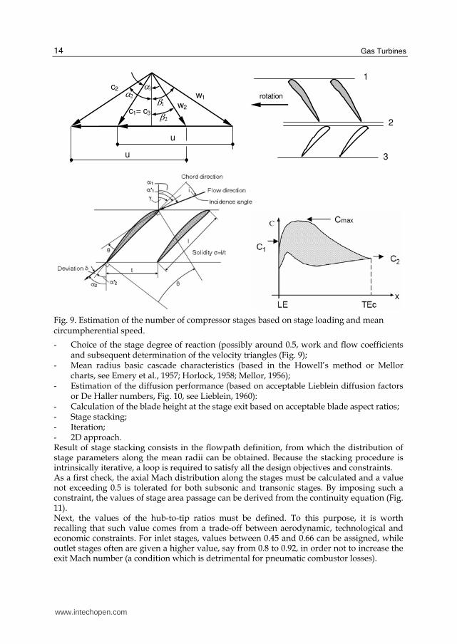
Fig. 9. Estimation of the number of compressor stages based on stage loading and mean circumpherential speed.
- Choice of the stage degree of reaction (possibly around 0.5, work and flow coefficients and subsequent determination of the velocity triangles (Fig. 9);
- Mean radius basic cascade characteristics (based in the Howell’s method or Mellor charts, see Emery et al., 1957; Horlock, 1958; Mellor, 1956);
- Estimation of the diffusion performance (based on acceptable Lieblein diffusion factors or De Haller numbers, Fig. 10, see Lieblein, 1960):
- Calculation of the blade height at the stage exit based on acceptable blade aspect ratios; - Stage stacking; - Iteration; - 2D approach. Result of stage stacking consists in the flowpath definition, from which the distribution of stage parameters along the mean radii can be obtained. Because the stacking procedure is intrinsically iterative, a loop is required to satisfy all the design objectives and constraints. As a first check, the axial Mach distribution along the stages must be calculated and a value not exceeding 0.5 is tolerated for both subsonic and transonic stages. By imposing such a constraint, the values of stage area passage can be derived from the continuity equation (Fig. 11). Next, the values of the hub-to-tip ratios must be defined. To this purpose, it is worth recalling that such value comes from a trade-off between aerodynamic, technological and economic constraints. For inlet stages, values between 0.45 and 0.66 can be assigned, while outlet stages often are given a higher value, say from 0.8 to 0.92, in order not to increase the exit Mach number (a condition which is detrimental for pneumatic combustor losses).
www.intechopen.com

Advances in Aerodynamic Design of Gas Turbines Compressors
15
Fig. 10. Lieblein’s Diffusion Factor (DLi) level versus solidity for given flow and work coefficient (left). Iso De Haller number in the φ, ψ diagram (right).
Fig. 11. Corrected mass flow over stage area passage as function of the axial Mach number.
Despite its relative simplicity, meanline 1D methods based on stage-stacking techniques still play an important role in the design of compressor stages as also demonstrated by Sun & Elder, 1998. In their work, a numerical methodology is used for optimizing a stator stagger setting in a multistage axial-flow compressor environment (seven-stage aircraft compressor) based on a stage-by-stage model to 'stack' the stages together with a dynamic surge prediction model. A direct search method incorporating a sequential weight increasing factor technique (SWIFT) was then used to optimize stagger setting, while the objective function was penalized externally with an updated factor which helped to accelerate convergence. A recent example of how 1D models can still be used in the preliminary design of axial compressors is given by Chen et al., 2005. In their work, a model for the optimum design of a compressor stage, assuming a fixed distribution of axial velocities, is presented. The absolute inlet and exit angles of the rotor are taken as design variables. Analytical relations between the isentropic efficiency and the flow coefficient, the work coefficient, the flow angles and the degree of reaction of the compressor stage were obtained. Numerical examples were provided to illustrate the effects of various parameters on the optimal performance of the compressor stage.
Corr
ecte
d m
ass flo
w /
Passage
are
a [
kg/(
sm
2)]
www.intechopen.com
Gas Turbines
16
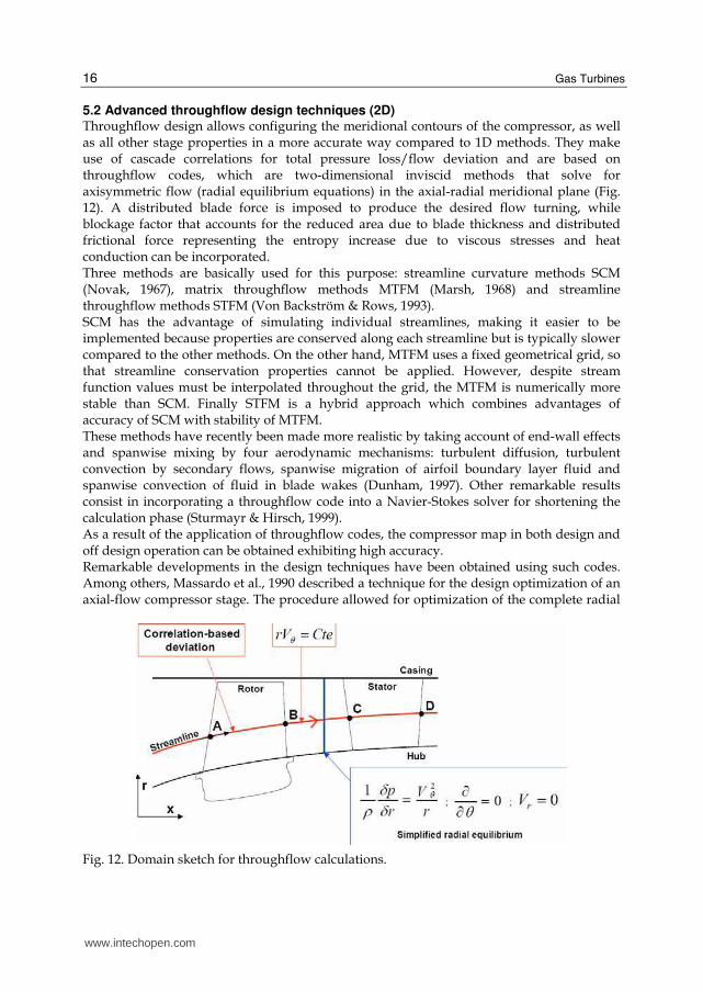
5.2 Advanced throughflow design techniques (2D) Throughflow design allows configuring the meridional contours of the compressor, as well as all other stage properties in a more accurate way compared to 1D methods. They make use of cascade correlations for total pressure loss/flow deviation and are based on throughflow codes, which are two-dimensional inviscid methods that solve for axisymmetric flow (radial equilibrium equations) in the axial-radial meridional plane (Fig. 12). A distributed blade force is imposed to produce the desired flow turning, while blockage factor that accounts for the reduced area due to blade thickness and distributed frictional force representing the entropy increase due to viscous stresses and heat conduction can be incorporated. Three methods are basically used for this purpose: streamline curvature methods SCM (Novak, 1967), matrix throughflow methods MTFM (Marsh, 1968) and streamline throughflow methods STFM (Von Backström & Rows, 1993). SCM has the advantage of simulating individual streamlines, making it easier to be implemented because properties are conserved along each streamline but is typically slower compared to the other methods. On the other hand, MTFM uses a fixed geometrical grid, so that streamline conservation properties cannot be applied. However, despite stream function values must be interpolated throughout the grid, the MTFM is numerically more stable than SCM. Finally STFM is a hybrid approach which combines advantages of accuracy of SCM with stability of MTFM. These methods have recently been made more realistic by taking account of end-wall effects and spanwise mixing by four aerodynamic mechanisms: turbulent diffusion, turbulent convection by secondary flows, spanwise migration of airfoil boundary layer fluid and spanwise convection of fluid in blade wakes (Dunham, 1997). Other remarkable results consist in incorporating a throughflow code into a Navier-Stokes solver for shortening the calculation phase (Sturmayr & Hirsch, 1999). As a result of the application of throughflow codes, the compressor map in both design and off design operation can be obtained exhibiting high accuracy. Remarkable developments in the design techniques have been obtained using such codes. Among others, Massardo et al., 1990 described a technique for the design optimization of an axial-flow compressor stage. The procedure allowed for optimization of the complete radial
Fig. 12. Domain sketch for throughflow calculations.
www.intechopen.com

Advances in Aerodynamic Design of Gas Turbines Compressors
17
Fig. 13. Optimization procedure proposed in Massardo et al., 1990
distribution of the geometry, being the objective function obtained using a throughflow calculation (Fig. 13). Some examples were given of the possibility to use the procedure both for redesign and the complete design of axial-flow compressor stages. Howard & Gallimore, 1993, incorporated a viscous throughflow method into an axial compressor design system such that the meridional velocity defects in the endwall region and consequently blading could be designed that allowed for the increased incidence, and low dynamic head, near the annulus walls. A very interesting application of a throughflow multiobjective design optimization has been recently given by Oyama & Liou, 2002. In this paper, a throughflow code based on the streamline curvature method is used along with a multiobjective evolutionary algorithm to design a four-stage compressor (Fig. 14, left) for maximization of the overall isentropic efficiency and the total pressure ratio. The diffusion factor was constrained to avoid designs involving flow separation. Total pressure and solidities at the rotor trailing edges, and flow angles and solidities at the stator trailing edges were considered as design parameters. In Fig. 14 (right), the final Pareto optimal solutions are plotted which reveal a significant superiority with respect to the baseline compressor from which the optimization started. The procedure made it also possible to obtain the full span distribution of design variables. e.g. the solidity of a blade which maximized one objective (see, for example, Fig. 14).
5.3 Advanced cascade design techniques (2D) A great benefit in compressor design for maximum performance can derive from advanced 2D cascade aerodynamic design using both direct and indirect methods.
Direct methods
These are design methods where a blade-to-blade geometry is first assessed and subsequently analyzed using available CFD flow solvers. Then, shape modifications take place and resulting geometries evaluated until an acceptable or even optimal configuration is found. Iterative methods perfectly suit for this purpose, so that optimization loops are often used in the framework of this approach. Among optimization techniques available today, evolutionary algorithms (Goldberg, 1989; Schwefel, 1995) are preferable to other “local” methods since they have revealed to be powerful tools in handling multimodal, non convex and multi-objective problems. Gradient-based optimization methods are still in use only for special “quadratic” cases.
www.intechopen.com

Gas Turbines
18
Fig. 14. Throughflow optimization of a multistage compressor (from Oyama & Liou, 2002).
Obayashi, 1997 faced the multi-objective optimization problem of maximizing the pressure rise and efficiency of compressor cascades with a Pareto-Genetic Algorithm and a Navier-Stokes solver. Pierret, 1999 used an artificial neural network coupled with a Navier-Stokes solver to maximize the efficiency and/or operating range of two-dimensional compressor cascades and then staggered them in radial direction to obtain the three dimensional blade. Köller et al., 2000 and Küsters et al., 2000 developed a new family of compressor airfoils, characterized by low total pressure losses and larger operating range with respect to standard Controlled Diffusion Airfoils (CDA), using a gradient optimization method and an inviscid/viscous code. Until today, the use of evolutionary techniques in combination with CFD codes for solving multi-objective optimization problems in compressor aerodynamics has been limited by the tremendous computational effort required. Since the large majority of the computational time is spent in the evaluation process of the objective function, a faster solution approach to calculate the flow field would be more appropriate. From this point of view, the use of Euler solvers with integral boundary layer approach are more desirable than Navier-Stokes codes, at least to predict flow quantities in the vicinity of the design point of the machine. On the other hand, the available evolutionary optimization techniques are not enough effective in exploiting information from a population of candidate solutions to the optimization
www.intechopen.com

Advances in Aerodynamic Design of Gas Turbines Compressors
19
problem, so that the number of generations required to get the optimum is usually great, thus penalizing the convergence process. A powerful evolutionary optimization code was developed by Toffolo & Benini, 2003 to support the development of a new design methodology of optimal airfoils for axial compressors (Benini & Toffolo, 2004). In fact, the ultimate goal of compressor cascade design is to create a blade with maximum pressure rise and minimum total pressure loss along with an acceptable tolerance to incidence angles variations. A number of different design choices can be carried out to reach this scope. Considering a cascade of airfoils, the flow may be turned by a high cambered profile at low incidence angles or, equivalently, by a low cambered profile having marked positive incidence. In this respect, the shape of the profile plays an important role because it affects the nature of the boundary layer on the suction side and therefore the amount of profile losses. On the other hand, the designer may use a high solidity cascade in order to decrease the aerodynamic loading on a single profile, thus reaching the maximum pressure rise with the whole blade row, or may adopt a low solidity cascade to minimize the friction losses for a prescribed pressure rise. All these choices involve a decision-making process that makes the design a challenging task. An option to handle this problem is to parameterize the shape of the airfoil first, e.g. by using Bézier parametric curves (see Fig. 15). Next, a proper problem formulation is needed, e.g. to maximize pressure ratio and minimize total pressure losses across the cascade for a given inlet Mach number, inlet and outlet flow inclinations (fixed flow deflexion). Moreover, in order to assure efficient off-design operation and acceptable profile thickness, one can impose a constraint regarding maximum allowable total pressure losses over the operating range of the cascade; for a generic cascade, for instance the total pressure loss can be
measured in five operating conditions defined by βi-β1*=0, ±2.5 deg, ±5 deg and compared to the one of the design: to satisfy the constraint, the following condition had to be verified at
each operating point i, i.e. / * 2 1,...,5i iω ω ≤ ∀ = , being ω the total pressure loss coefficient
of the cascade.
θout
■ Bezier Control
- - - - Bezier Polygon
θinl
(x(i),yCL(i)+δ (i))
(x(i),yCL(i))
(x(i),yCL(i)-δ (i))
Fig. 15. Geometry parameterization of an airfoil using Bezier curves; squares represent control points of Bezier curves (left). I-type grid used in the simulations of a compressor cascades (right). From Benini & Toffolo, 2002.
www.intechopen.com

Gas Turbines
20
An efficient algorithm can be used to handle the problem. A typical multiobjective evolutionary strategy (Schwefel, 1995) with genetic diversity preserving mechanism (GeDEM) can be used (Fig. 16, left) to obtain Pareto-optimal solutions (Fig. 16 right). The shape of the Pareto front confirms that at low pressure ratios it is possible to increase profile loading without penalizing efficiency in a very significant way; on the other hand, as the flow turning moves toward its maximum, a sudden drop in the profile efficiency is unavoidable. It is worth noting that the individuals belonging to the Pareto front “dominate” the cascades of NACA 65 profiles. In particular, the cascade of NACA 65-8-10, NACA 65-12-10 and NACA 65-15-10 are dominated by individuals A, B, C with respect to profile efficiency (PR being fixed), and by individuals A1, B1, C1 with respect to pressure ratio (profile efficiency being fixed).
Initial
random
population
Survival
of the
fittest
GeDEM
Evaluation
(Pareto
ranking)
Reproduction
( crossover +
mutation)
Parents’
selection
STOP
Max
generation
no.?
Yes
No
A
A1
B
B1
C
C1
Fig. 16. Scheme of the optimization used for cascade optimization (left). Pareto front of the optimization compared with performance figures of NACA 65 cascades (right). PR=Pressure ratio, w=total pressure loss coefficient. From Benini & Toffolo, 2002.
Fig. 17. Comparison between non optimal (left) and optimal (right) Mach number contour plot in a transonic compressor cascade (from Ahmadi, 1998).
Inverse methods
In inverse design, the required cascade performance is specified and the blade shape is sought accordingly. Although widely used in both academia and industry, they are far from
www.intechopen.com

Advances in Aerodynamic Design of Gas Turbines Compressors
21
being as accurate as direct methods. The reason for this relies in the simplifications which characterize them, particularly that inviscid flow equations (Euler equations) are solved. In 2D cascades, performance is defined by the design specification of either the flow properties on one or both sides of the blade, typically pressure, velocity or Mach number distribution (Lighthill, 1945; Giles & Drela, 1987; Leonard & Van Den Braembussche, 1992). A noticeable application of inverse methods for the design of transonic compressor cascade is given by Ahmadi, 1998, who implemented a cell-vertex finite volume method on unstructured triangular meshes. In this design method, the mass-averaged swirl schedule and the blade thickness distribution were prescribed. The design method then provided the blade shape that would accomplish this loading by imposing the appropriate pressure jump across the blades and satisfying the blade boundary condition. The method was first validated for a compressor cascade and then used to redesign a transonic ONERA cascade with the aim of removing the passage shock (Fig. 17).
5.4 Advanced 3D design techniques
Direct methods
Advanced optimization techniques can be of great help in the design of 3D compressor blades when direct methods are used. These are usually very expensive procedures in terms of computational cost such that they can be profitably used in the final stages of the design, when a good starting solution, obtained using a combination of 1D and/or 2D methods, is already available. Moreover, large computational resources are necessary to obtain results within reasonable industrial times. Examples of 3D designs of both subsonic and transonic compressor bladings are today numerous in the open literature.
Direct methods involving optimization techniques and direct objective evaluation
Among others, Lee & Kim, 2000 developed a numerical optimization technique combined with a three-dimensional Navier-Stokes solver to find an optimum shape of a stator blade in an axial compressor through calculations of single stage rotor-stator flow. For numerical optimization, searching direction was found by the steepest decent and conjugate direction methods, and the golden section method was used to determine optimum moving distance along the searching direction. The object of present optimization was to maximize efficiency. An optimum stacking line was also found to design a custom-tailored 3-D blade for maximum efficiency with the other parameters fixed. Sieverding et al., 2004 showed an example of advanced 3D design of industrial compressors blades, which typically require a wider range from surge to choke than typical gas turbine compressors in order to meet the high volume flow range requirements of the plant in which they operate. The method combined a parametric geometry definition method, a powerful blade-to-blade flow solver and an optimization technique (breeder genetic algorithm) with an appropriate fitness function. Particular effort has been devoted to the design of the fitness function for this application which includes non-dimensional terms related to the required performance at design and off-design operating points. It has been found that essential aspects of the design (such as the required flow turning, or mechanical constraints) should not be part of the fitness function, but need to be treated as so-called "killer" criteria in the genetic algorithm. Finally, it has been found worthwhile to examine the effect of the weighting factors of the fitness function to identify how these affect the performance of the sections. It is worth
www.intechopen.com

Gas Turbines
22
noting that the system has been tested on the design of a repeating stage for the middle stages of an industrial axial compressor and the resulting profiles showed an increased operating range compared to an earlier design using NACA65 profiles. A multiobjective design optimization method for 3D compressor rotor blades was developed by Benini, 2004, where the optimization problem was to maximize the isentropic efficiency of the rotor and to maximize its pressure ratio at the design point, using a constraint on the mass flow rate. Direct objective function calculation was performed iteratively using the three-dimensional Navier-Stokes equations and a multi-objective evolutionary algorithm featuring a special genetic diversity preserving method was used for handling the optimization problem. In this work, blade geometry was parameterized using three profiles along the span (hub, midspan and tip profiles), each of which was described by camber and thickness distributions, both defined using Bézier polynomials. The blade surface was then obtained by interpolating profile coordinates in the span direction using spline curves. By specifying a proper value of the tangential coordinate of the first midspan and the tip pro- files’ control point with respect to the hub profile, the effect of blade lean was achieved. Results confirmed the superiority of optimized leaned profiles with respect to the baseline configuration as far as efficiency and pressure ratio were concerned. Performance enhancement derived from a drastic modification in the shock structure within the blade channel which led to less severe shock losses (Fig. 18). Computational time was huge, involving about 2000 CPU hours on a 4-processor machine.
Fig. 18. Performance map and Mach number contours of baseline and optimized compressor configurations (from Benini, 2004).
www.intechopen.com

Advances in Aerodynamic Design of Gas Turbines Compressors
23
Direct methods involving optimization techniques and surrogate methods
In order to accelerate convergence toward the design optima without using intensive calls of a CFD solver, the use of approximations of the objective functions is becoming a popular technique. This is often referred to as a “response surface methodology” (RSM) and the practice of building an approximation of the true objective function is named “metamodelling” or “surrogate model construction”. Considering the competing requirements of computational economy, that is, employing as few data points as possible for constructing a surrogate model, and fidelity, that is, offering high accuracy in representing the characteristics of the design space, the assessment of the performance of surrogate models is of critical importance. In a recent work, Samad et al., 2008 multiple surrogate models for compressor optimization were considered including polynomial response surface approximation, Kriging, and radial basis neural networks. Once that the response surface was constructed, a sequential quadratic programming was used to search the optimal point based on these alternative surrogates. Three design variables characterizing the blade regarding sweep, lean, and skew were selected along with the three-level full factorial approach for design of experiment. The optimization was guided by three objectives aimed at maximizing the adiabatic efficiency, as well as the total pressure and total temperature ratios. The optimized compressor blades yielded lower losses by moving the separation line toward the downstream direction. The optima for total pressure and total temperature ratios were similar, but the optimum for adiabatic efficiency is located far from them. It was found that using multiple surrogates can improve the robustness of the optimization at a minimal computational cost.
Direct methods involving optimization techniques and adjoint equations
Another, remarkable, direct design optimization procedure makes use of adjoint methods (Chung, 2004). The formulation tries to encompass the drawbacks related to the long time required by traditional optimization techniques to converge. Adjoint methods are characterized by the definition of a classical Lagrangian functional, where the goal is to minimize a nonlinear objective function subject to the governing flow equations as constraints. The Lagrangian multipliers, called adjoint variables, are chosen such that they satisfy the functional, or adjoint equation, which eliminates the dependency of the optimality condition on flow variables. For the computation of adjoint variables, an adjoint sensitivity code needs to be built corresponding to the flow solver. However, the adjoint formulation enables the gradients of an objective function with respect to all design variables to be obtained simultaneously, at a negligible computational cost. This implies that a shape optimization based on the adjoint formulation becomes economical when the design involves a large number of design variables, as in 3D designs of complex geometry. However, obtaining accurate adjoint sensitivities is inherently difficult in internal flow problems due to the close proximities of the boundaries.
Inverse methods
In the last two decades, three-dimensional inverse design methods have emerged and been applied successfully for a wide range of designs, involving both radial/mixed flow turbomachinery blades and wings (Zangeneh, 1991; Demeulenaere & Van Den Braembussche, 1996; Dulikravich & Baker, 1999). Quite a new approach to the 3D design of axial compressor bladings has been recently proposed by Tiow, 2002. In this work, an inverse method was presented which is based on
www.intechopen.com

Gas Turbines
24
the flow governed by the Euler equations of motion and improved with viscous effects modelled using a body force model as given by Denton, 1987. However, contrary to the methods cited above, the methodology is capable of providing designs directly for a specific work rotor blading using the mass-averaged swirl velocity distribution.
Fig. 19. Surface Mach number and geometry of inverse designed and final blades (from Tiow, 2002).
Fig. 20. Comparison of blade loading distributions of an original supersonic blade, a new design (prescribed by inverse mode), and a reference blade (R2-56 blade) for a given pressure ratio (left); comparison of passage Mach number distributions at 95% span (from Dang et al., 2003).
Moreover, the methodology proposed by Tiow, 2002 joins the capabilities of an inverse design with the search potential of an optimization tool, in this case the simulated annealing algorithm (Kirkpatrick et al, 1983). The entire computation required minimal human intervention except during initial set-up where constraints based on existing knowledge may be imposed to restrict the search for the optimal performance to a specified domain of interest. Two generic transonic designs have been presented, one of which referred to compressor rotor, where loss reductions in the region of 20 per cent have been achieved by imposing a proper target surface Mach number which resulted in a modified blade shape (Fig. 19).
www.intechopen.com
Advances in Aerodynamic Design of Gas Turbines Compressors
25
An interesting application of a three-dimensional viscous inverse method was developed by Dang et al., 2003 ad applied to the design and analysis of a supersonic rotor, where aspiration was applied to enhance the operating range of a compressor. Results in Fig. 20 showed that an optimum combination of pressure-loading tailoring with surface aspiration can lead to a minimization of the amount of sucked flow required for a net performance improvement at design and off-design operations. By prescribing a desired loading distribution over the blade the placement of the passage shock in the new design was about the same as the original blade. However, the passage shock was weakened in the tip region where the relative Mach number is high.
6. Conclusion
Gas turbine compressors, either stationary or aeronautical, have reached a relatively mature level of development and performance. Nevertheless, the availability of advanced materials for blade construction makes it possible to rich levels of aerodynamic loading never experienced in the past while preserving high levels of on-off design efficiency. This holds especially for highly-subsonic and transonic blades, where tangential velocities are now becoming higher that 600 m/s, thus leading to stage pressure ratios of 2 and more. In fact, transonic bladings make it possible to reduce the number of stages for a prescribed total compression ratio, thus leading to huge savings in compressor costs, weight and complexity. To properly design such machines, multiobjective and multicriteria problems are to be dealt with which claim for rigorous and robust procedures, more often assisted by solid mathematical tools that help the designer to complete his/her skills and experience. In view of the above, continuous effort is currently being spent in building advanced design techniques able to tackle the problem efficiently, cost-effectively and accurately. Plenty of design optimization techniques has been and are being developed including standard trial-and-error 1D procedures up to the most sophisticated methods, such as direct or indirect methods driven by advanced optimization algorithms and CFD. Advanced techniques can be used in all stages of the design. In the field of 1D, or meanline methods, correlation-based prediction tools for loss and deviation estimation can be calibrated and profitably used for the preliminary design of multistage compressors. 2D methods supported by either throughflow or blade-to-blade codes in both a direct and an indirect approach, can be used afterwards, thus leading to a more accurate definition of the flow path of both meridional and cascade geometry. To enhance the potentialities of such methods, optimization algorithms can be quite easily used to drive the search toward optimal compressor configurations with a reasonable computational effort. Detailed 3D aerodynamic design remains peculiar of single stage analyses, although several works have described computations of multistage configurations, either in steady and unsteady operations. However, the latter is an approach suitable for verification and analysis purposes, thus with a limited design applicability. 3D design optimization techniques can realistically be used if local refinements of a relatively good starting geometry is searched for. On the other hand, if more general results are expected, simplified design methods are mandatory, such as those based on supervised learning procedures, where surrogate models of the objective functions are constructed. Other very promising techniques include adjoint methods, where the number of design iteration can be potentially reduced by an order of magnitude if local derivatives of physical quantities with respect to the decision variables are carefully computed.
www.intechopen.com
Gas Turbines
26
7. References
Ahmadi, M. (1998). Aerodynamic inverse design of turbomachinery cascades using a finite volume method on unstructured meshes. Inverse Problems in Science and Engineering, Vol. 6, Issue 4, pp. 281-298, ISSN: 1741-5977.
Benini, E. (2004). Three-Dimensional Multi-Objective Design Optimization of a Transonic Compressor Rotor. Journal of Propulsion and Power, Vol. 20, No. 3 (May/June), pp. 559-565, ISSN: 0748-4658.
Benini, E. & Toffolo, A. (2002). Development of High-Performance Airfoils for Axial Flow Compressors Using Evolutionary Computation. Journal of Propulsion and Power, Vol. 18, No. 3, pp. 544-554, ISSN: 0748-4658.
Casey, M.V. (1987). A mean-line prediction method for estimation the performance characteristics of an axial compressor stage. Proceedings of the IMechE 1987, Turbomachinary Efficiency Prediction and Improvement, pp. 145–55, ISBN: 0852986300.
Chen, L.; Luo, J.; Sun, F. ; Wu, C. (2005). Optimized efficiency axial-flow compressor. Applied Energy, Vol. 81, No. 4, pp. 409-419, ISSN: 0306-2619.
Chung, J.; Martin G. & Lee, K. D. (2004). Aerodynamic Design of 3D Compressor Blade Using an Adjoint Method. AlAA Paper 2004-0027.
Dang, T. Q.; Van Rooij, M. & Larosiliere, L. M. (2003). Design of Aspirated Compressor Blades Using Three-Dimensional Inverse Method. NASA/TM—2003-212212.
Demeulenaere, A. & Van Den Braembussche, R. A. (1996). Threedimensional inverse method for turbomachinery blading design. ASME paper 96-GT-39.
Denton J. D. & Dawes W. N. (1999). Computational fluid dynamics for turbomachinery design. Journal of Mechanical Engineering Science, IMechE Proc. Part C, Vol. 213, No. C2, pp. 107-124, ISSN: 0022-2542.
Denton, J. D. (1986). The use of a distributed body force to simulate viscous effects in 3D flow calculations. ASME paper 86-GT-144.
Dulikravich, G. S. & Baker, D. P. (1999). Aerodynamic shape inverse design using a Fourier series method. AIAA paper 99-0185.
Dunham, J. (1997). Modelling of spanwise mixing in compressor through-flow computations. Proceedings of the Institution of Mechanical Engineers, Part A: Journal of Power and Energy, Vol. 211, No. 3, pp. 243-251, ISSN: 0957-6509.
Emery J. C.; Herrig L. J.; Erwin J. R. & Felix A. R. (1957). Systematic Two-Dimensional Cascade Test of NACA 65-Series Compressor Blades at Low Speeds. NACA Rept. 1368.
Giles, M. & Drela, M. (1987). Two-dimensional transonic aerodynamic design method. AIAA Journal, Vol. 25, No. 9, 1199-1205, ISSN: 0001-1452.
Ginder, R.B. & Harris D. (1989). AGARD Pep Working Group 18: Compressor Test Case E/CO-3, Royal Aerospace Establishment.
Goldberg, D. E. (1989). Genetic Algorithms for Search, Optimization and Machine Learning, Reading, MA, Addison Wesley, ISBN: 0201157675.
Horlock J. H. (1958). Axial-flow Compressors, Butterworths, London, UK. Howard, M. A. & Gallimore, S. J. (1993). Viscous Throughflow Modeling for Multistage
Compressor Design. Journal of Turbomachinery. Vol. 115, Issue 2, pp. 296-305. Howell, A. R. (1942). The present Basis of Axial Flow Compressor Design: Part 1 Cascade
Theory and performance. 2095. Aeronautical Research Council Reports and Memoranda.
www.intechopen.com

Advances in Aerodynamic Design of Gas Turbines Compressors
27
Kirkpatrick, S.; Gelatt, C. D. & Vecchi, M. P. (1983). Optimization by simulated annealing. Science, Vol. 220, pp. 671–680.
Koch, C. C. & Smith, L. H. (1976). Loss sources and magnitudes in axial-flow compressors. ASME Transactions, Journal for Engineering and Power, Vol. 98, No. 3, pp. 411-424.
Köller, U.; Mönig, R.; Küsters, B. & Schreiber, H.-A. (2000). Development of Advanced Compressor Airfoils for Heavy-Duty Gas Turbines – Part I: Design and Optimization. Journal of Turbomachinery, Vol. 122, pp. 397-405, ISSN: 0889-504X.
Küsters, B.; Schreiber, H.-A.; Köller, U. & Mönig, R., (2000). Development of Advanced Compressor Airfoils for Heavy-Duty Gas Turbines – Part II: Experimental and Theoretical Analysis. Journal of Turbomachinery, Vol. 122, pp. 406-415, ISSN: 0889-504X.
Lee S.-Y. & Kim, K.-Y. (2000) Design optimization of axial flow compressor blades with three-dimensional Navier-Stokes solver. KSME International Journal. Vol. 14, No. 9, pp. 1005-1012, ISSN: 1226-4865.
Leonard O. & Van Den Braembussche, R. (1992). Two-dimensional Transonic aerodynamic design method. Journal of Turbomachinery, Vol. 114, No.3, pp. 553-560, ISSN: 0889-504X.
Lieblein, S. (1960). Incidence and deviation angle correlations for compressor cascades. Trans. ASME Journal of Basic Engineering, Vol. 82, pp. 575–587.
Lighthill, M. (1945). A new method of two-dimensional aerodynamic design. Aeronautical research Council RxM 2104.
Marsh, H. (1968). A digital computer program for the throughflow fluid mechanics in an arbitrary turbomachine using a Matrix Method. Aeronautical Research Council. 3509.
Massardo, A.; Satta, A. & Marini M. (1990). Axial Flow Compressor Design Optimization: Part II—Throughflow Analysis. Journal of Turbomachinery. Vol. 112, No. 3, pp. 405-411, ISSN: 0889-504X.
Mellor G. (1956). The NACA 65-Series Cascade Data. Gas Turbine Laboratory Charts, MIT, Cambridge, MA.
Miller, G.R.; Lewis, G.W. & Hartmann M.J. Jr (1961). Shock Losses in Transonic Compressor Blade Rows, Trans. ASME Journal of Engineering for Power, Vol. 83, July, pp., 235–242.
Novak, R. E. (1967). Streamline curvature computing procedures for fluid-How problems. J. Eng. Power (Trans. ASME), Vol. 89, No. 4, pp. 478-490.
Obayashi, S. (1997). Pareto Genetic Algorithm for Aerodynamic Design Using the Navier-Stokes Equations, In: Genetic Algorithms in Engineering and Computer Science, Quagliarella et al. Eds., Wiley, New York.
Oyama, A. & Liou, M.-S. (2002). Multiobjective Optimization of a Multi-stage Compressor Using Evolutionary Algorithm. AIAA paper 2002-3535.
Pierret, S. (1999). Three-Dimensional Blade Design by Means of an Artificial Neural Network and Navier-Stokes Solver. VKI Lecture Series 1999-02 on Turbomachinery Blade Design Systems.
Samad, A.; Kim, K.-Y.; Goel, T.; Haftka, R.T. & Shyy, W. Multiple (2008). Surrogate Modeling for Axial Compressor Blade Shape Optimization, Journal of Propulsion and Power. Vol. 24, No. 2, pp. 302-310, ISSN: 0748-4658.
www.intechopen.com

Gas Turbines
28
Schobeiri, M. T. (1996). Advanced Compressor Loss Correlations, Part I: Theoretical Aspects. International Journal of Rotating Machinery. Vol. 3, No. 3, pp. 163-177, ISSN (printed): 1023-621X.
Schwefel, H.-P. (1995). Evolution and optimum seeking, Wiley, New York, ISBN: 0471571482. Sieverding, F.; Ribi, B. & Casey, M. (2004). Design of Industrial Axial Compressor Blade
Sections for Optimal Range and Performance. Journal of Turbomachinery , Volume 126, No. 2, pp. 323-332, ISSN: 0889-504X.
Smith, L. H. (1970). Casing Boundary Layers in Multistage Axial Flow Compressors, in L. W. Dzung, Flow Research in Blading, Elsevier.
Smith, L.H. (1970). Casing Boundary Layers in Multistage Axial Flow Compressors, in Flow Research in Blading (L. W. Dzung Ed.), Elsevier.
Sturmayr, A. & Hirsch, Ch. (1999). Throughflow model for design and analysis integrated in a three-dimensional Navier-Stokes solver. Proceedings of the Institution of Mechanical Engineers, Part A: Journal of Power and Energy. Vol. 213, No. 4, pp. 263-273, ISSN: 0957-6509.
Sun, J. & Elder, R. L. (1998). Numerical optimization of a stator vane setting in multistage axial-flow compressors. Proceedings of the Institution of Mechanical Engineers, Part A: Journal of Power and Energy. Vol. 212, No 4, pp. 247-259, ISSN: 0957-6509.
Suter, P. (1960). Theoretische Untersuchung uber die Seitenwandgrenzschikter in Axialverdichtern. Mitt. Inst. Therm. Turbomasch. ETH Zürich, n. 5.
Tiow, W. T.; Yiu, K. F. C. & Zangeneh M. (2002). Application of simulated annealing to inverse design of transonic turbomachinery cascades. Proceedings of the Institution of Mechanical Engineers, Part A: Journal of Power and Energy, Vol. 216, No. 1, pp. 59-73, ISSN: 0957-6509.
Toffolo, A. & Benini, E. (2003). Genetic Diversity as an Objective in Evolutionary Algorithms. Evolutionary Computation, Volume 11, No. 2, pp. 151-167, ISSN 1063-6560.
Von Backström & T.W. & Roos, T.H. (1993). The streamline through-flow method for axial turbomachinery flow analysis. Papers from the Eleventh International Symposium on Air Breathing Engines, Tokyo, Japan, pp. 347 - 354.
Wisler, D. C.; Koch, C. C. & Smith, L. H. Jr. (1977). Preliminary design study of advanced multistage axial flow core compressors. NASA Report -CR-135133.
Zangeneh, M. (1991). A compressible three-dimensional design method for radial and mixed flow turbomachinery blades. International Journal of Numerical Methods in Fluids. Vol. 13, pp. 599–624, ISSN: 0271-2091.
www.intechopen.com

Gas TurbinesEdited by Gurrappa Injeti
ISBN 978-953-307-146-6Hard cover, 364 pagesPublisher SciyoPublished online 27, September, 2010Published in print edition September, 2010
InTech EuropeUniversity Campus STeP Ri Slavka Krautzeka 83/A 51000 Rijeka, Croatia Phone: +385 (51) 770 447 Fax: +385 (51) 686 166www.intechopen.com
InTech ChinaUnit 405, Office Block, Hotel Equatorial Shanghai No.65, Yan An Road (West), Shanghai, 200040, China
Phone: +86-21-62489820 Fax: +86-21-62489821
This book is intended to provide valuable information for the analysis and design of various gas turbineengines for different applications. The target audience for this book is design, maintenance, materials,aerospace and mechanical engineers. The design and maintenance engineers in the gas turbine and aircraftindustry will benefit immensely from the integration and system discussions in the book. The chapters are ofhigh relevance and interest to manufacturers, researchers and academicians as well.
How to referenceIn order to correctly reference this scholarly work, feel free to copy and paste the following:
Ernesto Benini (2010). Advances in Aerodynamic Design of Gas Turbines Compressors, Gas Turbines,Gurrappa Injeti (Ed.), ISBN: 978-953-307-146-6, InTech, Available from:http://www.intechopen.com/books/gas-turbines/advances-in-aerodynamic-design-of-gas-turbines-compressors