advances in environmental biology - aensiweb.net 2014/1092-1103.pdfadvances in environmental...
TRANSCRIPT
Advances in Environmental Biology, 8(12) July 2014, Pages: 1092-1103
AENSI Journals
Advances in Environmental Biology ISSN-1995-0756 EISSN-1998-1066
Journal home page: http://www.aensiweb.com/AEB/
Corresponding Author: Tayeb Hedayati, MSc in department of civil engineering, Zanjan branch, Islamic Azad University,
Zanjan, Iran
Study on Soil Parameters Effect on Seismic Performance of Buried Pipelines 1Mehran Javanmard and 2Tayeb Hedayati 1Assistant professor, University of Zanjan, Zanjan , Iran. 2 MSc in department of civil engineering, Zanjan branch, Islamic Azad University, Zanjan, Iran.
ARTICLE INFO ABSTRACT
Article history:
Received 2 June 2014
Received in revised form 13 August 2014
Accepted 28 September 2014
Available online10 October 2014
Keywords: pipe line, soil parameters, Praxis,
seismic
Life line system, and its equipment’s, provides essential services today, so seismic
performance analysis in modern industrial area is exigent. We analyze and compare the
performance analysis of gas bored pipes in various soil compactions with finite element method. We create a finite element model with three soil types and compare them.
Finally, the soil with best performance is presented.
© 2014 AENSI Publisher All rights reserved.
To Cite This Article: Mehran Javanmard and Tayeb Hedayati, Study on Soil Parameters Effect on Seismic Performance of Buried
Pipelines. Adv. Environ. Biol., 8(12), 1092-1103, 2014
INTRODUCTION
Today, vital arteries play an important role in urban modern industrial areas. This vital arteries system
includes buried oil and gas pipes, underground electricity transfer cable, underground water distribution
systems, etc. vital arteries system and the related equipments provide essential services in today lives. However,
function necessity of its types is determined in modern industrial areas. Not only destruction of vital arteries has
severe economical consequences, but also might have reverse effect on environment and quality of life after an
earthquake. Examining past earthquakes and severe damages incurred to vital arteries in these quakes indicates
the importance of studying vital arteries behavior under earthquake.
Earthquake can damage buried pipes in two ways. One group of these damages is due to the earthquake
wave propagation phenomena and the other group is related to the permanent ground deformation, which in the
follow is called PGD. Faulting, landslide, lateral spreading, as well as settlement are among the events
categorized in permanent ground deformation [6]. One of the uncertainties about design and implementation of
buries pipes is that after pipe placement in the ground depth whether material or the soil density filling the
trenches has any effect on this pipeline performance. To this end, interaction between soil and pipe under
different situations is investigated. So, finite element method and Plaxis software were used. Studied models
have a same input stimulation and various soils such that soil parameters effect on seismic performance of pipe
will be determined.
Numeric Modeling Method for Buries Pipelines vs. Earthquake:
Finite element method (FEM) might be used to analysis and design any pipeline in any loading situations
including explosive charge and is applied for many cases of designing pipeline. Figure 1 shows an example of
modeling by FEM method. Pipe can be modeled by linear element of beam (or pressure pipe). Near the loaded
zone boundary, length of beam/pipe elements should not be more than pipe diameter. The model must conform
to pipe material as well as non-linear geometry states (major deformations). In one case with more generality,
axial symmetric and sell elements might be used to study the appropriate connections and other factors. Soil is
modeled by lateral and axial springs which can provide non-linear behavior of force-displacement.

1093 Mehran Javanmard and Tayeb Hedayati 2014
Advances in Environmental Biology, 8(12) July 2014, Pages: 1092-1103
Fig. 1: Finite element (beam type) of buried pipe with soil and supports.
Analysis for Earth Quake Risk:
Earth shake causes random movements. This results in pipe deformation along with soil. Buried pipes in
areas subject to seismic waves move together with soil which is against the local movements of earth like
liquefaction, landslide, and fault deviation. Maximum strain in soil is estimated as follows [3]:
soil
PGV
c
(1)
Where;
PGV= maximum earth speed in pipe place
C= speed of seismic wave in soil at pipe place. Wave propagation speed can be considered 13000 f/s, unless
otherwise be justified.
A) Continuum pipe:
A continuum pipe has joints connected to the pipe body with significant toughness and perseverance (they
are typically called restrained joints). An example of these pipes is steel pipe with weld (single pass lab shear
weld, two pass lap shear weld and butt welding).
Force of pipe body design and joints is the minimum of F1 or F2 that F1 is a force assuming pipe is
dependant completely on soil (that is, pipe does not slide in soil) and F2 is the final force which soil can transfer
to the pipe.
Suppose that earth strain is transferred to pipe without slide, so
(1)
(2)
(3)
Where
A= pipe cross section
E= pipe Young`s module
tu final friction force that is applied to pipe body in axial direction (force in length unit)
λ seismic wave length in soil in pipe place. Wave length can be considered 6500 foot unless otherwise is
justified.
B) Sectional pipe:
A sectional pipe has joints connected to pipe body with low toughness and perseverance (they are typically
called unrestrained joints). For example, a cast-iron or a PVC pipe has washer joints with compression gasket
filler. It is supposed that earth strains are transferred to relative axial movements between pipes which should be
considered in pipe joints. If relative movements of joint are higher than that in the joint, then pipe pieces in the
connection point will be separated under tension or pieces resist against each other under pressure, probably
result in merging two pieces together or local bending of pipe wall occurs. Axial movement (in both direction of
pipe soil
PGV
c
1 pipeAEF
24
utF

1094 Mehran Javanmard and Tayeb Hedayati 2014
Advances in Environmental Biology, 8(12) July 2014, Pages: 1092-1103
axial shortening and axial length increase) that a joint must be conformed to it, is obtained by the following
equation:
int 7jo p soilL (4)
Where: LP= pipe length
Laboratory tests show that axial toughness and perseverance is different among joints. Therefore, weak
joints relative to neighboring strong joints are subject to more relative movements. In 1990, O'Rourke [5]
showed that for cast-iron pipe with sealed joints by lead, about one percent of joints were under movement 3
times more than average movements of joint, while 0.1 percent were under movement 5 times more than
average movement of joint. To design purposes, it is recommended to use movements 7 times more than
average movements. And it is expected that damages would not be more than one in ten thousand joint. For
example, suppose that PGV is 50 cm/sec and piece length is 16 foot, then:
int
507 7 16 12 0.17( )
13000 12 2.54jo p
PGVL in
c
(5)
Transaction between soil and pipe:
Buried pipes influenced by ground movements or incurred major charges to pipes like great temperature
changes might be under high bending tensions or tensile loads. Cause of ground movement can result in
different subsidence. The resulted deformations due to the earth subsidence are generally monotonic and do not
have any effects on fatigue life and weariness of pipe. Usually, transaction between soil and pipe in buried
pipeline during earthquake or explosion is a complicated matter; during earthquake or explosion, non-linear
behavior of soil components make it more complicated. Most of this complication is due to soil features. In
major pipeline analysis, using complete finite element model that shows the system non-linear behavior in the
best way is recommended. Normally, various models are used to show transaction of soil and pipe which
include:
A) Continuum model, in which a complex mathematical formula is developed for flexible pipes with finite
length that are in a semi-finite soil medium.
B) Soil finite element grid model, which in this non-linearity of system complexity becomes model.
C) Winkler`s beam on foundation model (BNMF), in which soil is considered by the independent springs on
certain point of the pipe.
Practically, among the above-mentioned models, BNMF model is used extensively due to simplicity of
mathematical facilities and the capability of applying non-linear behavior. Following this topic, the method of
modeling in BNMF for continuum and discontinuous pipelines will be provided.
As said before, an exact method for analyzing and designing buried pipes is considering non-plastic
behavior for transaction between soil and pipe. ALA agenda [1] has provided the following method for
analyzing and designing transaction between soil and pipe. In this method, non-linear tension-strain relations for
steel pipes are considered. This model needs definition of the following parameters:
- Bending and axial resistance of pipe
- Longitudinal and transverse resistance of soil regarding internal friction and soil cohesion ratio
In this method, soil resistance is modeled normally as a complete elastic-plastic behavior with spring. The
applied load on the pipe is modeled by a series of springs with non-linear behavior, as below Figure.
Fig. 2: Modeled soil with Winkler non-linear springs [1].
Soil modeling:
For some states of soil movements applied on the pipeline (like earthquake and explosion), it is expected
that the pipe slide in the soil. So, load curves of soil deformation should be non-linear. In the next part,
formulation extracted from America`s regulations [2] for soil springs are provided.
1095 Mehran Javanmard and Tayeb Hedayati 2014
Advances in Environmental Biology, 8(12) July 2014, Pages: 1092-1103
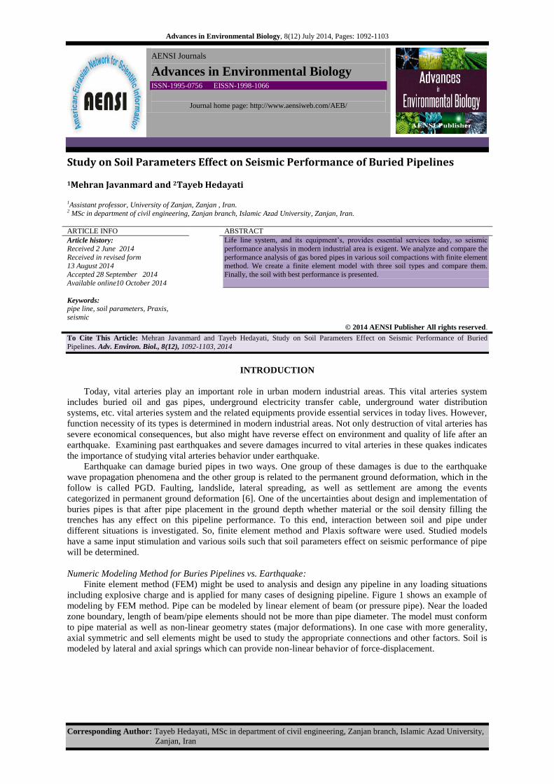
Axial spring of soil:
Regarding to the soil embankment material used for trench of pipeline, soil axial spring features are
estimated. Though this is appropriate only when pipeline movement response relative to neighboring
embankment is not significantly affected by trench outside soil, in the below Figure ideal behavioral curve of
axial soil spring is shown.
Fig. 3: Ideal behavioral curve of axial soil spring.
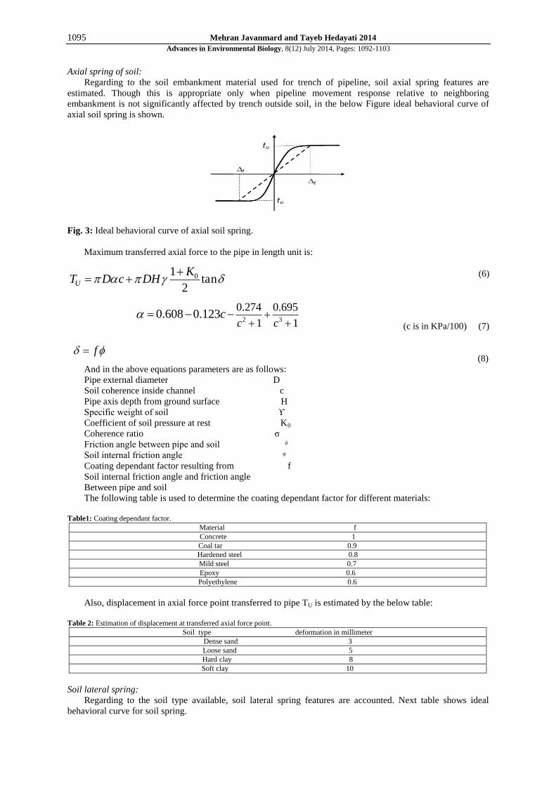
Maximum transferred axial force to the pipe in length unit is:
(6)
2 3
0.274 0.695
1 10.608 0.123
c cc
(c is in KPa/100) (7)
(8)
And in the above equations parameters are as follows:
Pipe external diameter D
Soil coherence inside channel c
Pipe axis depth from ground surface H
Specific weight of soil ϒ
Coefficient of soil pressure at rest K0
Coherence ratio σ
Friction angle between pipe and soil ᵟ
Soil internal friction angle ᵠ
Coating dependant factor resulting from f
Soil internal friction angle and friction angle
Between pipe and soil
The following table is used to determine the coating dependant factor for different materials:
Table1: Coating dependant factor.
Material f
Concrete 1
Coal tar 0.9
Hardened steel 0.8
Mild steel 0.7
Epoxy 0.6
Polyethylene 0.6
Also, displacement in axial force point transferred to pipe TU is estimated by the below table:
Table 2: Estimation of displacement at transferred axial force point.
Soil type deformation in millimeter
Dense sand 3
Loose sand 5
Hard clay 8
Soft clay 10
Soil lateral spring:
Regarding to the soil type available, soil lateral spring features are accounted. Next table shows ideal
behavioral curve for soil spring.
01tan
2U
KT D c DH
f

1096 Mehran Javanmard and Tayeb Hedayati 2014
Advances in Environmental Biology, 8(12) July 2014, Pages: 1092-1103
Fig. 4:. Ideal curve for lateral soil.
Maximum lateral force transferred to the pipe in length unit is:
(9)
(10)
(11)
Horizontal bearing capacity factor for clay (for soil Nch
Without coherence it is zero)
Horizontal bearing capacity factor (for soil without Nqh
Internal friction angle it is zero)
Provided equations and the below table for Nch and Nqh value determination are obtained by experimental
results.
Table 3: Nch and Nqh value determination.
Nqh value for soil with internal friction angle different from above table value can be calculated by
interpolation.
In addition, displacement in lateral force point transferred to pipe Pu is obtained by the following equation:
(12)
Soil vertical spring:
Soil spring features for states of uplift or bearing are different. Probably, available soil features will be used,
while for soil spring in uplifting state embankment features will be considered. The following Figure shows the
ideal behavioral curve for soil vertical spring.
u ch qhP N cD N HD
2 3
91 1
ch
c dN a bx
x x
2 3 4qhN a b x c x d x e x
0.04 0.1 0.152
P
DH D D

1097 Mehran Javanmard and Tayeb Hedayati 2014
Advances in Environmental Biology, 8(12) July 2014, Pages: 1092-1103
Fig. 5: Ideal curve for soil vertical springs.
A) Uplift:
The provided equation in this section to determine vertical force of springs to the soil is based on test results
in small-scale and analysis models. This equation is applicable for surface and pipe`s being on surface or depth
is based on ratio.
(13)
Upward vertical force ratio (for the soil without coherence is zero) Nch
Upward vertical force for sand (for the soil without internal friction angle is zero) Nqh
10H
D
Where
2 10CV
HN
D
44qV q
HN N
D
(14)
Displacement in the place of vertical force transferred to the pipe Qu is equal to:
For dense sand to the loose sand Δqu value is equal to:
For hard clay to soft clay Δqu value is equal to:
0.1 0.2 0.2H H D B) Vertical bearing
(15)
Nc and Nq and Nϒ are bearing capacity ratios.
(16)
0.18 2.5N e
(17)
Nq is calculated based on the equation in the last section.
Displacement in the place of vertical force transferred to pipe Qd is equal to:
Table4: Displacement estimation in place of vertical force transferred.
Soil type deformation
Grained soil 0.1D
Cohesive soil 0.2D
u qVCVQ N cD N HD
2exp( tan )tan 452
qN
0.01 0.02 0.1H H D
2
2d c q
DQ N cD N HD N
2 0.001cot 0.001 exp tan 0.001 tan 45
2cN

1098 Mehran Javanmard and Tayeb Hedayati 2014
Advances in Environmental Biology, 8(12) July 2014, Pages: 1092-1103
Fig. 6: Cohesive soil resistance rations for various values of soil friction.
Modeling buried pipe in Plaxis software:
Plaxis is software used for analyzing deformations and stability in geotechnical engineering projects.
Usually, in major geotechnical issues, there is a need for an advanced behavioral model for modeling non-linear
and time-dependant behavior of soils relative to desired purpose. By this software, one can model excavation
and embankment with various loading and boundary conditions using 6 and 15 nodal triangle elements. First
edition of this software was commissioned by water resource management of Netherlands in Delft Industrial
University in 1987 to analysis earth dams constructed on soft soil in low level areas of this country. Then in
1993 it was extended and confirmed and supported by Center for Civil Engineering Research and Codes
institution. In this software, behavioral models of Moher-Colomb, hardening hyperbolic model, softening model
(Cam-Clay) and soft soil creep model are applicable. Also, developing and excavation process is done with this
software by enabling and disenabling elements in calculation steps. One example of this application is layer
analyzing in slope, dam and tunnel stability.
In the present research model 15 nodal triangle elements are used. Regarding that pipe length is more than
its cross section, for convenience 2D model is used under plane strain 16. In addition, to achieve element
relation between soil and pipe interface element 17 is used. On the other hand, to raise modeling accuracy
elements surrounding pipe are considered finer. Furthermore, tunnel element with elasto-plastic behavior for
pipe modeling is applied.
Fig. 7: Finite element model of buried pipe with 15 nodal element meshing.
Velocimetry applied for this model was harmonic which has various types with pga= 0.4g and 5Hz
frequency, but all their time is 5 seconds.

1099 Mehran Javanmard and Tayeb Hedayati 2014
Advances in Environmental Biology, 8(12) July 2014, Pages: 1092-1103
Fig. 8: Velocimetry applied for models.
Material:
Soil:
Used soil in this research is the combination of the following soils. In the present study, based on the
hardening soil model three types of soil are used for modeling. Hardening soil model parameters are provided in
the below Figure.
Fig. 9: Hardening soil model parameters.
1) Firoozkouh standard sand, 2) sand with 15 percent clay, and 3) construction sand
Firoozkouh 161 sand has density of dry grain 2/65Kg/cm3. Also, sand with clay used in this study is the
combination of Firoozkouh 161 sand and clay in the ratio of 1 to 0.15.
Soils parameters are obtained by triaxial tests in the state of undrained, as well as soil direct shear in Soil &
Foundation Laboratory of Tehran University. Additionally, σ and ß Rayliegh parameters related to damping are
obtained by trial and error.
Table 5: Soils parametric features.
Material Internal friction angle φuu(deg)
Dilation angle
(deg)
( )urE Mpa
value
value e0 Undrained cohesion cuu(kg/cm2)
Firoozkouh standard sand 30 1.9 35.8 0.98 0.647
0.152
Clay sand 32.5 3.7 53.2 0.98 0.682 0.192
Construction sand 33 4.2 76 1 0.637 0.258
Modeled pipe features are as follows:
Table 6: Used pipe features.
Nominal diameter
in
material Internal diameter
mm
thickness
mm
Elastic module،E
GPa
Bending rigidity،EI
kN.m^2
Axial rigidity،EA, kN
4 steel 101.6 5.1 200 485.5 340507.43
Model dimension is a rectangular with 1.5 m height and 2 m width. The dimensions are selected such as
boundary effects are minimized.

1100 Mehran Javanmard and Tayeb Hedayati 2014
Advances in Environmental Biology, 8(12) July 2014, Pages: 1092-1103
Transaction between soil and pipe:
In this section, transaction between soil and pipe and influential parameters on them are studied. Compared
parameters are 1) pressure on the pipe, and 2) strains on the pipe.
The effect of relative density of soil around pipe on pipe relative deformation:
To study the effect of soil density on seismic behavior of pipe two models are used. This means that two
same stimulations once in loose sand and once in dense sand were applied on the pipe. Soil features in loose and
dense states are as follows.
Table7: Sandy soils with various densities
( )urE mpa
( )Deg
( )Deg
B –value 0e
Dr (%) type
35.8 1.9 32.5 0.98 0.737 40 Loose sand
82.7 44 38.3 1 0.439 70 Dense sand
Fig. 10: Comparing strains on pipe in loose and dense sand.
To study relative density of soil around pipe on pipe relative deformation, diagram of c nodal strains in the
right of pipe element was drawn and is shown in Figure 1.
As it can be seen in Figure 10 when soil is denser strain is more. Regarding this increase it can be said that
when the soil is denser, pipe and soil coordination is more and transaction between soil and pipe is increased
too. So, incurred force on pipe is higher.
The effect of relative density of soil around pipe on incurred force on pipe:
Incurred force in node C is considered to study the effect of relative density of soil around pipe on incurred
force on pipe. So one can say that when the soil around pipe is denser transaction between soil and pipe is
raised. This result is consistent with findings about strains in the last section.
Fig. 11: Comparison of incurred force on pipe for loose and dense sand.

1101 Mehran Javanmard and Tayeb Hedayati 2014
Advances in Environmental Biology, 8(12) July 2014, Pages: 1092-1103
There are two views about density effect on transaction between soil and pipe. First view: when the soil
around pipe is loose, then there is more resonance in soil; that is velocity resonance factor increases. In turn, this
increase raises the velocity and therefore incurred force on pipe grows.
Second view: when the soil around pipe is dense. Soil density around pipe raises the coordination between
pipe and soil. In addition, density increase makes lateral force on pipe more. Thus, in this way incurred force on
pipe increases. According to the comparison of bearing and strain on the pipe in two cases of dense and loose
soil it can be concluded that transaction between soil and pipe is higher when soil around pipe is denser.
Therefore, effect of lateral bearing on pipe in the case of density is higher than effect of velocity increase in
loose soil.
Effect of relative density on resonance ratio results:
Figure 12 is drawn to determine the relation between soil density around pipe and resonance phenomena.
This diagram shows resonance ratio in different levels of soil for a model with 0.4 g velocity and 5Hz frequency
in both loose and dense soil. As it can be seen, whether under pipe level in depth of 65 cm or higher levels in
trench, there is no difference in resonance. It can be said that density has no effect on resonance factor.
Fig. 12: Resonance factor based on cycle numbers.
Effect of soil type on incurred force on soil from pipe:
In developed models to study effect of soil type around pipe on incurred force on pipe, three types of soil,
Firoozkouh 161 sandy soil, Firoozkouh clay sand, and construction sand under same conditions were used.
Features of these soils are provided in table 2. According to Figure 13 it can be seen that Firoozkouh 161 sand
has the most bearing on pipe. In addition, bearing amount, in the case of Firoozkouh clay sand, shows the least
bearing.

1102 Mehran Javanmard and Tayeb Hedayati 2014
Advances in Environmental Biology, 8(12) July 2014, Pages: 1092-1103
Fig. 13: Comparison of bearing on buried pipe for three types of soil.
Fig. 15: Comparisons of pipe strains under cyclic charge in two types of construction and clay sand soils
As it is clear strains amount on pipe in cohesive soil is more than construction sand soil, and this implies
that cohesion increase results in rising incurred force on soil from pipe.
Conclusion:
According to the obtained results from this research it can be said that first high density of soil makes
incurred force on pipe more, and therefore results in more relative deformation of pipe. So it is recommended
that soil used around pipe in trench should be screened and has low density. Also, it can be said that more the
soil cohesion less the incurred bearing on pipe, and pipe will show better performance.
REFERENCES
[1] American Lifeline Alliance (ALA), 2001. Guidelines for the design of Buried steel pipe, American Society
of Civil Engineering (ASCE).
[2] American Lifeline Alliance (ALA), 2005. Seismic Guidelines for Water Pipelines.
[3] Davis, C.A., J.P. Bardet, 2000. Response of buried corrugated metal pipes to earthquakes, Journal of
geotechnical and environmental engineering.

1103 Mehran Javanmard and Tayeb Hedayati 2014
Advances in Environmental Biology, 8(12) July 2014, Pages: 1092-1103
[4] Kramer, S.L., 1996. Geotechnical Earthquake Engineering, Prentice Hall.
[5] O’Rourke, M.J., 2003. Earthquake engineering Handbook, Buried Pipeline, Chapter 23, CRC Press.
[6] PIANC., 2001. Seismic Design Guidelines for Port Structures, Balkema (http://www.pianc.org).