advantages of deformation measurements for a …...advantages of deformation measurements for a deep...
TRANSCRIPT

Advantages of deformation measurements for adeep excavation of an unstable slope in order toimplement a hydropower development
C. DidulescuFaculty of Geodesy, Department of Surveying and Cadastre, Technical University of Civil EngineeringBucharest, Lacul Tei Blvd., No. 122-124, sector 2, Bucharest, Romania
D. Păunescu, C. PopescuFaculty of Hydrotechnics, Hydraulic Structures Department, Technical University of Civil EngineeringBucharest, Lacul Tei Blvd., No. 122-124, sector 2, Bucharest, Romania
Abstract. In order to implement the LivezeniHydro Power Plant on the Jiu River, theconstruction of the dam required a diversionchannel through the left bank. Constructing thediversion channel imposed a deep trench excavationand thus steep slope which often slid in time. In thisregard, a bored and anchored column piles supportwas made, designed for the slope movementcontrol. In this site there is also an importantrailway. The stringent conditions of displacementcontrol could be ensured by adopting acomprehensive monitoring system usinginclinometers. The inclinometer system had toprovide both information about the displacement ofthe column wall and railway track, also revealingany potential crest and slope instability. With thefinished columns, the excavations began under theirshelter and as the excavation progressed also thetwo rows of anchorage were rigged-up.Measurements made during the carrying out of theexcavation revealed, at a given moment, that thedisplacements were larger than designed due to theposition of initially estimated bedrock. This fact ledto the resizing of the anchorage system. Themismatch between the geological configuration,highlighted by the initial studies and the revealedreality on-site was highlighted exclusively by theinclinometer systems, this being one of the majorfacts that made possible to ensure the stabilityworks. Without this detailed and well integratedmonitoring system, the slope stability and trafficsafety would have been definitely compromised.
Keywords. Slope displacement, inclinometer,monitoring system
1 Introduction
One of the reasons that changed the slope stabilitywas the excavation at the toe of the slope. This
paper presents how the excavation for the diversionchannel for Livezeni Hydro Power Plant, at the toeof the slope, created instability conditions and howthey were revealed. The chosen solution for theslope instability control was to create a bored andanchored column pile support.The integrated monitoring system of the slopemovement consisted of column inclinometers (notedIC1 to IC5) slope piezometers (noted IP1 to IP9)and topo-geodesic landmarks. The lay-out of themonitoring system complied with the imposedscheme by the initial DE project phase (DE - Detailsfor Execution), with the purpose of an independentmonitoring for the pile columns wall, the abutmentmass rock, the railway track and adjacent railwaysworks, the slope to the ridge. This system wasimplemented so that one could diagnose theoccurrence of possible instabilities and their causes.
2 Geological conditions highlighted inthe works phase. The stability of thecolumn pile wall
In the case of the drilled columns piles theconstruction works for the left bank slopeprotection, in the Livezeni dam area, on the JiuRiver, TUCEB (Technical University of CivilEngineering Bucharest) participated as expertconsultant.The geological study, originally conducted by acompany that activates in the field of geology, wasbased on Vertical Electrical Sounding (VES) andboreholes that revealed a transversal profile, in theaxis of dam, without extending it in the columnswall area. This profile was the basis for TUCEBconsultants for the elaboration of the supportinfrastructure, depicted in the design TP phase(Technical Project) and DE (DE - Details forExecution).The first cues that the profiles were inaccurateemerged in the stage of the boring of the first pile
2
columns when the contractor complained that thepenetration of the bedrock was achieved at higherlevels than those highlighted by the geologicalsurvey, thus requiring the reduction of the height ofthe foundation, motivated by extremely highstrength of rock.In these circumstances the consultant expert fromTUCEB requested additional on site geological andgeotechnical drillings in order to clarify thedisaccords noted in the works phase.The request was rejected by the beneficiary on thegrounds of delays already affecting the schedule,and opted for the matching of the design accordingto the progress of the works. Thus the geologicalconfiguration was completed on the ongoing siteinformation related to the progress of the works.This measure imposed very thorough tracking ofthe evolution of the geological data that emergedfrom the site and the follow-up of the behavior ofthe structure and slope through a permanentmonitoring system. The decisions about adapting ormodifying the constructive solution in order to beoperational and that it ensured the safety conditionsboth for rail traffic in the area and for the personnelinvolved in the execution had to be taken on thedata provided by the ongoing works.The chosen monitoring system allowed theupdating of the geological information and moreaccurate location of the mobile geological layer,regardless of their origin. The mobile geologicallayers are responsible for the increase in activity ofthe thrust-fault, while formations contribute to thestability increase of the pile columns embedding.The position of boundary surface of the mobilegeological layers was relative to that depicted in theinitial studies, and the revealing of the real lay-outis extremely important. If the boundary would havebeen lower than the initial estimates, the stress andstrain on the active thrust, corroborated with theimplementation of a under-dimensioned designwould inevitably lead to a considerable increase inthe embedding efforts for the pile columns.This was the reason for the swift intervention of thedesigner and expert consultant, stated also in theinitial project, both in TP and DE phases. As soonas the bed rock would be found 30 cm lower thanexpected, the consultant had to adapt the design.Unfortunately this provision could not be respectedobjectively by the contractor due to the presence ofbreccia boulders, found at higher elevations, whichmisled into thinking that the actual bed-rock ishigher. Moreover, the accredited geologists werenot able to note this facts, on the base of the debrisexamination resulted from drilling the pile columns,
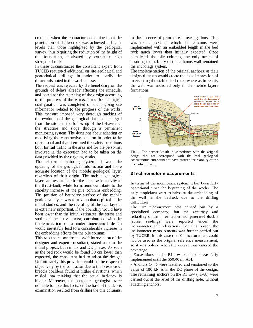
in the absence of prior direct investigations. Thiswas the context in which the columns wereimplemented with an embedded length in the bedrock much lower than initially expected. Oncecompleted, the pile columns, the only means ofensuring the stability of the columns wall remainedthe anchorage system.The implementation of the original anchors, at theirdesigned length would create the false impression ofintersecting the stabile bed-rock, where as in realitythe wall was anchored only in the mobile layersformations.
Fig. 1 The anchor length in accordance with the originaldesign did not correspond with the real geologicalconfiguration and could not have ensured the stability of thepile columns wall.
3 Inclinometer measurements
In terms of the monitoring system, it has been fullyoperational since the beginning of the works. Theonly suspicions were relative to the embedding ofthe wall in the bedrock due to the drillingdifficulties.The "0" measurement was carried out by aspecialized company, but the accuracy andreliability of the information had generated doubts(some readings were reported under theinclinometer sole elevation). For this reason theinclinometer measurements was further carried outby TUCEB. In this case the “0” measurement couldnot be used as the original reference measurement,so it was redone when the excavations entered thenext stage:- Excavations on the R1 row of anchors was fullyimplemented until the 550.00 m. ASL;- Anchors 1- 40 were installed and tensioned to thevalue of 180 kN as in the DE phase of the design.The remaining anchors on the R1 row (41-68) werecarried out at the level of the drilling hole, withoutattaching anchors;
3
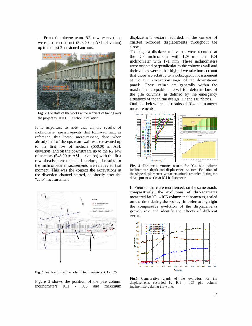
- From the downstream R2 row excavationswere also carried out (546.00 m ASL elevation)up to the last 3 tensioned anchors.
Fig. 2 The state of the works at the moment of taking over
the project by TUCEB. Anchor installation
It is important to note that all the results ofinclinometer measurements that followed had, asreference, this "zero" measurement, done whenalready half of the upstream wall was excavated upto the first row of anchors (550.00 m ASLelevation) and on the downstream up to the R2 rowof anchors (546.00 m ASL elevation) with the firstrow already pretensioned. Therefore, all results forthe inclinometer measurements are relative to thatmoment. This was the context the excavations atthe diversion channel started, so shortly after the"zero" measurement.
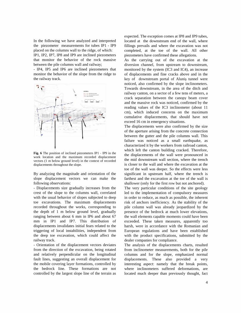
Fig. 3 Position of the pile column inclinometers IC1 - IC5
Figure 3 shows the position of the pile columninclinometers IC1 - IC5 and maximum
displacement vectors recorded, in the context ofcharted recorded displacements throughout theslope.The highest displacement values were recorded atthe IC3 inclinometer with 129 mm and IC4inclinometer with 171 mm. These inclinometerswere oriented perpendicular to the columns wall andtheir values were rather high, if we take into accountthat these are relative to a subsequent measurementat the first excavation stage of the downstreampanels. These values are generally within themaximum acceptable interval for deformations ofthe pile columns, as defined by the emergencysituations of the initial design, TP and DE phases.Outlined below are the results of IC4 inclinometermeasurements.
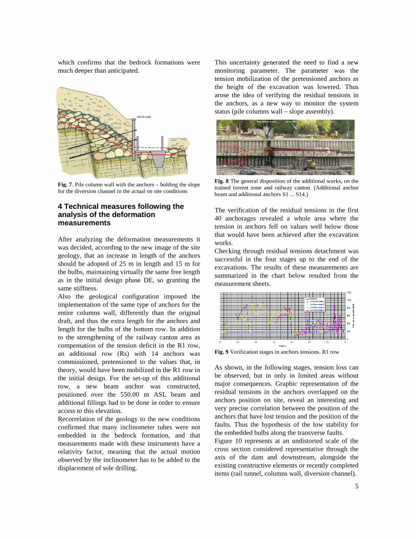
Fig. 4 The measurements results for IC4 pile columninclinometer, depth and displacement vectors. Evolution ofthe slope displacement vector magnitude recorded during thedevelopment works at IC4 inclinometer.
In Figure 5 there are represented, on the same graph,comparatively, the evolutions of displacementsmeasured by IC1 - IC5 column inclinometers, scaledon the time during the works, in order to highlightthe comparative evolution of the displacementsgrowth rate and identify the effects of differentevents.
Fig.5 Comparative graph of the evolution for thedisplacements recorded by IC1 - IC5 pile columninclinometers during the works
4
In the following we have analyzed and interpretedthe piezometer measurements for tubes IP1 - IP9placed on the columns wall to the ridge, of which:IP1, IP2, IP7, IP8 and IP9 are inclined piezometersthat monitor the behavior of the rock massivebetween the pile columns wall and railway;- IP4, IP5 and IP6 are inclined piezometers thatmonitor the behavior of the slope from the ridge tothe railway track.
Fig. 6 The position of inclined piezometers IP1 - IP9 in thework location and the maximum recorded displacementvectors (1 m below ground level) in the context of recordeddisplacements throughout the slope.
By analyzing the magnitude and orientation of theslope displacement vectors we can make thefollowing observations:- Displacements size gradually increases from thecrest of the slope to the columns wall, correlatedwith the usual behavior of slopes subjected to deeptoe excavations. The maximum displacementsrecorded throughout the works, corresponding tothe depth of 1 m below ground level, graduallyranging between about 6 mm in IP6 and about 67mm in IP1 and IP7. This distribution ofdisplacements invalidates initial fears related to thetriggering of local instabilities, independent fromthe deep toe excavation, which could affect therailway track.- Orientation of the displacement vectors deviatesfrom the direction of the excavation, being rotatedand relatively perpendicular on the longitudinalfault lines, suggesting an overall displacement forthe mobile covering layer formations, controlled bythe bedrock line. These formations are notcontrolled by the largest slope line of the terrain as
expected. The exception comes at IP8 and IP9 tubes,located at the downstream end of the wall, wherefillings prevails and where the excavation was notcompleted, at the toe of the wall. All otherpiezometers have confirmed these allegations.As the carrying out of the excavation at thediversion channel, from upstream to downstream,monitored by the system (IC3 and IC4), an increaseof displacements and fine cracks above and in thekey of downstream portal of Aluniş tunnel werenoticed, also confirmed by the slope inclinometers.Towards downstream, in the area of the ditch andrailway canton, on a sector of a few tens of meters, acrack separation between the canopy beam coverand the massive rock was noticed, confirmed by thereading values of the IC3 inclinometer (about 11cm), which induced concerns on the maximumcumulative displacements, that should have notexceed 16 cm in emergency situations.The displacements were also confirmed by the sizeof the aperture arising from the concrete connectionbetween the gutter and the pile columns wall. Thisfailure was noticed as a small earthquake, ascharacterized it by the workers from railroad canton,which left the canton building cracked. Therefore,the displacements of the wall were pronounced inthe mid downstream wall section, where the trenchis closer to the wall and where the excavation at thetoe of the wall was deeper. So the effects were lesssignificant in upstream half, where the trench isfarthest and the excavation at the toe of the wall isshallower (only for the first row but not anchored).The very particular conditions of the site geologyled to the implementation of compulsory measuresin order to reduce, as much as possible, the inherentrisk of anchors inefficiency. As the stability of thepile column wall was already jeopardized by thepresence of the bedrock at much lower elevations,the wall elements capable moments could have beenexceeded. These taken measures, apparently tooharsh, were in accordance with the Romanian andEuropean regulations and have been establishedwith the product specifications, submitted by thedealer companies for compliance.The analysis of the displacements charts, resultedfrom inclinometer measurements, both for the pilecolumns and for the slope, emphasized normaldisplacements. These also provided a veryinteresting aspect: namely that the break points,where inclinometers suffered deformations, arelocated much deeper than previously thought, fact
5
which confirms that the bedrock formations weremuch deeper than anticipated.
Fig. 7. Pile column wall with the anchors – holding the slopefor the diversion channel in the actual on site conditions
4 Technical measures following theanalysis of the deformationmeasurements
After analyzing the deformation measurements itwas decided, according to the new image of the sitegeology, that an increase in length of the anchorsshould be adopted of 25 m in length and 15 m forthe bulbs, maintaining virtually the same free lengthas in the initial design phase DE, so granting thesame stiffness.Also the geological configuration imposed theimplementation of the same type of anchors for theentire columns wall, differently than the originaldraft, and thus the extra length for the anchors andlength for the bulbs of the bottom row. In additionto the strengthening of the railway canton area ascompensation of the tension deficit in the R1 row,an additional row (Rs) with 14 anchors wascommissioned, pretensioned to the values that, intheory, would have been mobilized in the R1 row inthe initial design. For the set-up of this additionalrow, a new beam anchor was constructed,positioned over the 550.00 m ASL beam andadditional fillings had to be done in order to ensureaccess to this elevation.Recorrelation of the geology to the new conditionsconfirmed that many inclinometer tubes were notembedded in the bedrock formation, and thatmeasurements made with these instruments have arelativity factor, meaning that the actual motionobserved by the inclinometer has to be added to thedisplacement of sole drilling.
This uncertainty generated the need to find a newmonitoring parameter. The parameter was thetension mobilization of the pretensioned anchors asthe height of the excavation was lowered. Thusarose the idea of verifying the residual tensions inthe anchors, as a new way to monitor the systemstatus (pile columns wall – slope assembly).
Fig. 8 The general disposition of the additional works, on thetrained torrent zone and railway canton. (Additional anchorbeam and additional anchors S1 ... S14.)
The verification of the residual tensions in the first40 anchorages revealed a whole area where thetension in anchors fell on values well below thosethat would have been achieved after the excavationworks.Checking through residual tensions detachment wassuccessful in the four stages up to the end of theexcavations. The results of these measurements aresummarized in the chart below resulted from themeasurement sheets.
Fig. 9 Verification stages in anchors tensions. R1 row
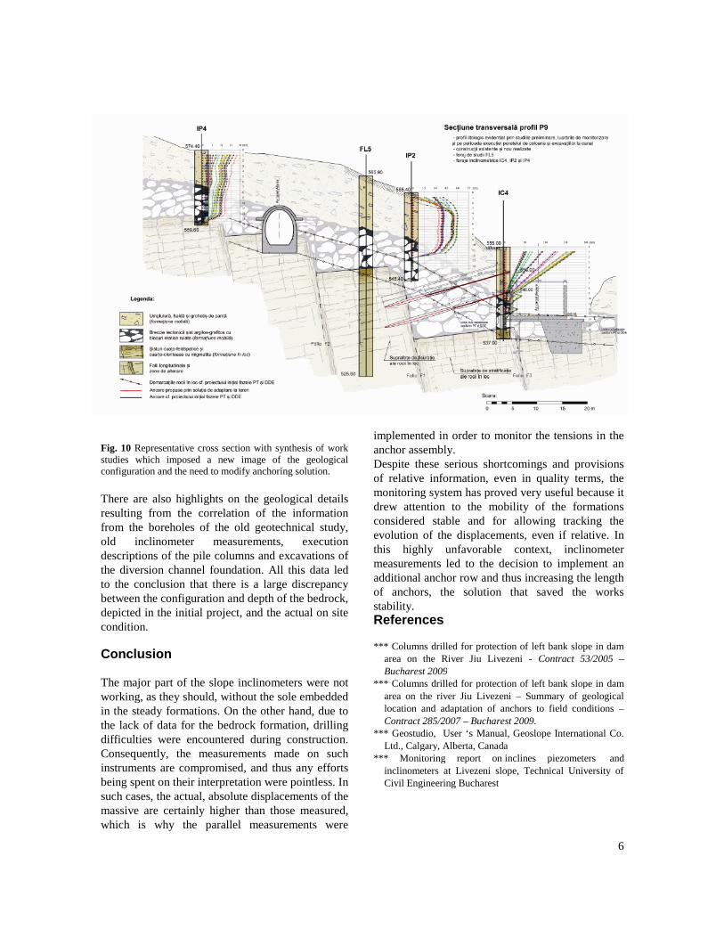
As shown, in the following stages, tension loss canbe observed, but in only in limited areas withoutmajor consequences. Graphic representation of theresidual tensions in the anchors overlapped on theanchors position on site, reveal an interesting andvery precise correlation between the position of theanchors that have lost tension and the position of thefaults. Thus the hypothesis of the low stability forthe embedded bulbs along the transverse faults.Figure 10 represents at an undistorted scale of thecross section considered representative through theaxis of the dam and downstream, alongside theexisting constructive elements or recently completeditems (rail tunnel, columns wall, diversion channel).
6
Fig. 10 Representative cross section with synthesis of workstudies which imposed a new image of the geologicalconfiguration and the need to modify anchoring solution.
There are also highlights on the geological detailsresulting from the correlation of the informationfrom the boreholes of the old geotechnical study,old inclinometer measurements, executiondescriptions of the pile columns and excavations ofthe diversion channel foundation. All this data ledto the conclusion that there is a large discrepancybetween the configuration and depth of the bedrock,depicted in the initial project, and the actual on sitecondition.
Conclusion
The major part of the slope inclinometers were notworking, as they should, without the sole embeddedin the steady formations. On the other hand, due tothe lack of data for the bedrock formation, drillingdifficulties were encountered during construction.Consequently, the measurements made on suchinstruments are compromised, and thus any effortsbeing spent on their interpretation were pointless. Insuch cases, the actual, absolute displacements of themassive are certainly higher than those measured,which is why the parallel measurements were
implemented in order to monitor the tensions in theanchor assembly.Despite these serious shortcomings and provisionsof relative information, even in quality terms, themonitoring system has proved very useful because itdrew attention to the mobility of the formationsconsidered stable and for allowing tracking theevolution of the displacements, even if relative. Inthis highly unfavorable context, inclinometermeasurements led to the decision to implement anadditional anchor row and thus increasing the lengthof anchors, the solution that saved the worksstability.References
*** Columns drilled for protection of left bank slope in damarea on the River Jiu Livezeni - Contract 53/2005 –Bucharest 2009
*** Columns drilled for protection of left bank slope in damarea on the river Jiu Livezeni – Summary of geologicallocation and adaptation of anchors to field conditions –Contract 285/2007 – Bucharest 2009.
*** Geostudio, User ‘s Manual, Geoslope International Co.Ltd., Calgary, Alberta, Canada
*** Monitoring report on inclines piezometers andinclinometers at Livezeni slope, Technical University ofCivil Engineering Bucharest