aeroelastic analysis of a transonic fan blade with low hub...
TRANSCRIPT
Journal of Power and Energy Engineering, 2015, 3, 362-372 Published Online April 2015 in SciRes. http://www.scirp.org/journal/jpee http://dx.doi.org/10.4236/jpee.2015.34049
How to cite this paper: Fu, Z.Z. and Wang, Y.R. (2015) Aeroelastic Analysis of a Transonic Fan Blade with Low Hub-to-Tip Ratio including Mistuning Effects. Journal of Power and Energy Engineering, 3, 362-372. http://dx.doi.org/10.4236/jpee.2015.34049
Aeroelastic Analysis of a Transonic Fan Blade with Low Hub-to-Tip Ratio including Mistuning Effects Zhizhong Fu, Yanrong Wang School of Energy and Power Engineering, Beijing University of Aeronautics and Astronautics, Beijing, China Email: [email protected] Received March 2015
Abstract This paper presents a comprehensive investigation of aeroelastic stability for a high aft-swept transonic fan blade with low hub-to-tip ratio. The evolution of the blade’s aeroelastic stability in the first bending modes is studied. A 3D flutter computation representing today’s industry stan-dard is performed. Steady state flow field and motion-induced unsteady pressures acting on the blade have been determined by a 3D Reynolds-Averaged Navier-Stokes (RANS) equations with a standard k-ε turbulence model. A weakly coupled (one-way) method has been employed to de-scribe the interaction between fluid and structure. The results of aerodynamic damping indicate a significant shock-driven risk. To increase the flutter margin by a viable method, a statistical mis-tuned aeroelastic stability investigation has been performed. It has been found that alternately intentional mistuning with a small blade frequency offset stabilizes the system effectively. How-ever, as the standard deviation of random mistuning reaches some critical values, the introduction of alternately intentional mistuning does not provide any additional stabilizing effects.
Keywords Aeroelastic Stability, Flutter, Turbomachinery, Mistuning
1. Introduction Aeroelastic problems in turbomachinery continue to attract the attention of industrial and academic researchers [1]-[5]. Classic aeroelastic phenomena include forced response and flutter. Forced response of rotor blades due to wake/rotor interaction or inlet distortion are synchronous with integer multiples of the shaft rotation rate (en-gine orders) [6]. Numerous studies of forced response of experimental and numerical character have been pub-lished in the past few decades [7]-[9]. Flutter, on the other hand, is asynchronous, and usually occurs at high re-duced velocities and/or large incidence angles. Flutter in turbomachinery is defined as an aeroelastic instability in the coupled fluid-structure system consisting of an oscillating blade surrounded by flowing gas. There are also many researchers working on it over the years with varying levels of complexity and details, ranging from 1D models to nonlinear, time-marched 3D computations with fully coupled fluid-structure models [10] [11].
Basically, there are three numerical methods for flutter prediction. First (“time domain”) method is based on
Z. Z. Fu, Y. R. Wang
363
the direct simulation of fully coupled fluid-structure system. This method could include almost any nonlinear characteristic and does not make any assumptions in regard to either reduced frequency or inter-blade phase an-gle. However, necessity of great amount of computational resources and time limits wide applications of this method. Second (“frequency domain”) method is based on calculation of eigenvalue problem of coupled fluid- structure system. Generally, positive imaginary part of the eigenvalue is a criterion for flutter occurrence. Bak-hle et al. [12] employed this method with harmonic balance technique to an experimental forward-swept fan encountered flutter at part-speed conditions during wind tunnel testing. Third (“energy”) method is based on calculating the sum of the work done by unsteady (linearized or nonlinear) aerodynamic forces. This method assumes that the flutter behavior is linear, positive aerodynamic work, i.e. energy transfer to the structure, indi-cating instability.
The flutter which is a self-excited aeroelastic instability phenomenon is the focus of this paper. The overall objective of the presented investigation is to determine the flutter risk for a transonic aft-swept fan blade with low hub-to-tip ratio when operating inside and outside the normal envelop of service parameters. Figure 1 shows a 3D view of the investigated fan blisk. The numerical investigation into the blade is first conducted with linear harmonic analysis method which remains the primary tool for flutter analysis for turbomachinery designs and then expanded into studies of blade mistuning. The linear harmonic analysis method is a sound and robust aeroelastic analysis approach and is widely used by many researchers [13] [14].
Mistuning as a result of manufacturing imperfection, field damage, or small geometry variations is inevitable. The research on this subject over the few past decades has shown that mistuning may drastically increase the vi-bration level of bladed disk and blisk [15]-[17]. A topic of particular interest to this investigation is the effect of random mistuning. The introduction of intentional mistuning has been proven to be an effective and practical way to alleviate flutter [18]-[20]. This paper has described the outcomes of the performed mistuned aeroelastic stability with a Monte Carlo simulation of random mistuning presented at the last.
2. Computational Model 2.1. Flow Simulation Model The aerodynamic forces were calculated by solving the 3D compressible Reynolds-Averaged Navier-Stokes (RANS) equations with a standard k-ε turbulence model through time-linearized method. Inflow boundary con-dition has been implemented by standard atmosphere with axial flow direction, and averaged static pressure was employed as outflow boundary condition. Tip clearance has not been modeled in the present study. The whole annulus model has been simulated to take into account nonzero inter-blade phase angle.
Figure 1. 3D view of the investigated fan blisk.

Z. Z. Fu, Y. R. Wang
364
A preliminary grid convergence work is shown in Figure 2 in which AMDR is explained further below. For the same boundary conditions and geometric domain, AMDRs have been calculated with a single passage CFD model under different mesh levels. As the cell number increases, AMDR has a valley value at a cell number of 650,000. Considering the computational resource and results accuracy, the CFD model of this paper contains 252,192 cells for one flow passage. The hub and blade view of employed CFD grid is shown in Figure 3. Oper-ating characteristic of this fan blade shown in Figure 4 is calculated through modifying static pressure of out-flow boundary. The followed aeroelstic analyses have been performed in load case A and load case B.
2.2. Structural Model To determine the blade oscillation modes, a modal analysis has been performed using. Figure 5 depicts the
0
Aer
odyn
amic
Mod
al D
ampi
ng R
atio
1 2 3 4 5 6 7 8 9 10 Cell Number ×105
1.5
1.55
1.65
1.75
1.85
1.8
1.7
1.6
×10-3
Figure 2. Evolution of AMDR as the cell number increasing.
Figure 3. Blade and hub view of the employed CFD grid.

Z. Z. Fu, Y. R. Wang
365
0.92
Rot
or T
otal
Pre
ssur
e R
atio
0.93 0.94 0.95 0.96 0.97 0.98 0.99 1 Mass Flow Rate/Mass Flow Rate at Choke
1.25
1.35
1.45
1.55
1.6
1.5
1.4
1.3
Load Case B
Load Case A
Figure 4. Operating characteristic of fan blade at design speed line.
Figure 5. Employed blade finite element model.
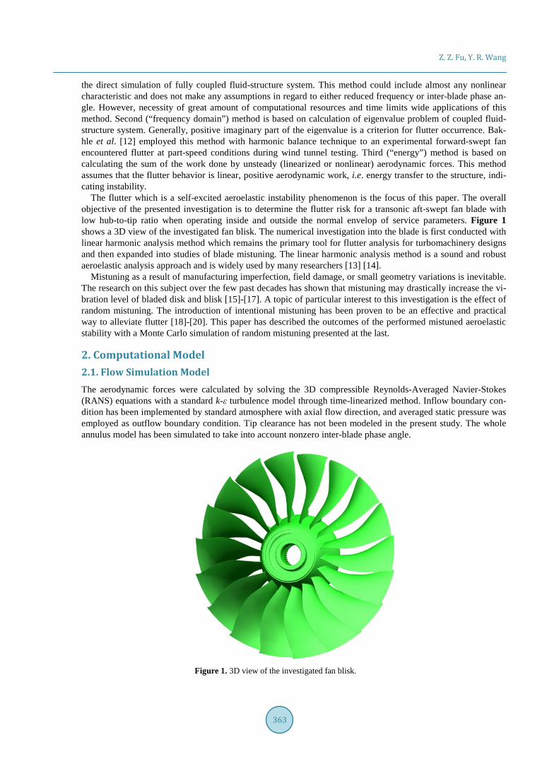
employed finite element model. The impact of disk on the blade modes has been ignored. In fact real disk-blade mode interaction does not occur for the lowest mode. The nodes at the disk interface have been constrained in all translational degrees of freedom. Rotational effects such as stress stiffening and spin softening have been considered by imposing a centrifugal loading on the entire domain. Aerodynamic pressure from steady solution has been included in static analysis. It assumes that the influence of flow condition on natural blade modes and frequencies can be neglected. The first three modes shown in Figure 6 are applied as moving surface boundary conditions to the later CFD analyses.
2.3. Aeroelastic Model The interaction between fluid and structure is here assumed to follow the weakly coupled (one-way) approach. That is, the airfoil is prescribed to oscillate harmonically in the flow field according to the elastic mode shape
Z. Z. Fu, Y. R. Wang
366
Mode1 Mode2 Mode3
Figure 6. The first three modes (total displacement). and the elastic eigenfrequency. The actual feedback influences on both mode shape and oscillation frequency from fluid inertia and stiffness are thereby ignored. The aerodynamic damping calculation consists of two major steps. The first step is to obtain the steady-state solution from a nonlinear flow simulation. The second step is to solve the linearized harmonic (unsteady) flow equations to obtain an estimation of aerodynamic damping. The details of employed method in this paper has not been disclosed, but can be found in [3]. AMDR is calculated based upon the concept of equivalent viscous damping which will be negative in case of aeroelastic instability.
( )aero
aero 222π cfd
W
qζ
ω= − (1)
3. Aerodynamic Damping Results In spite of extensive research work over the past 40 years, the exact flutter mechanisms are still somewhat diffi-cult to recognize due to many ways in which it can occur. But some parameters have been recognized as key factors by many researchers such as shock wave. The results presented in Figure 7 confirm that the load case A is predicted to be stable. Furthermore, the maximum AMDR of about 2% signifies an unusually strong aerody-namic coupling for this mode. Figure 8 reveals the steady state Mach number distribution at 80% span which is calculated from a single blade passage steady analysis for two load cases. The results are copied to three pas-sages to give a clear contour. The observed high velocity flow in the blade passage generates a strong shock near 70% chord length on the suction side in load case A which indicates a pressure jump exists at the two sides of shock. As the outflow static pressure increases, the shock moves from the trailing edge to the leading edge.
Figure 9 illustrates the unsteady pressure amplitude distribution on the airfoil surface due to 1st mode in two load cases, in which the values presented with red color are larger than that in blue regions. It is shown that the regions on suction surface close to blade tip regions reveal larger unsteady pressure amplitudes for both flow conditions. As mentioned before, the in-passage shock attaching to the blade surface generates a higher unsteady pressure amplitude which stems from shock oscillation. For these two load cases, the regions of high unsteady pressure amplitudes on pressure surfaces are closer to blade leading edge as the shock moves from blade trailing edge to leading edge. These differences of unsteady pressure amplitude distribution lead to the distinction of aerodynamic work distribution which is shown later.
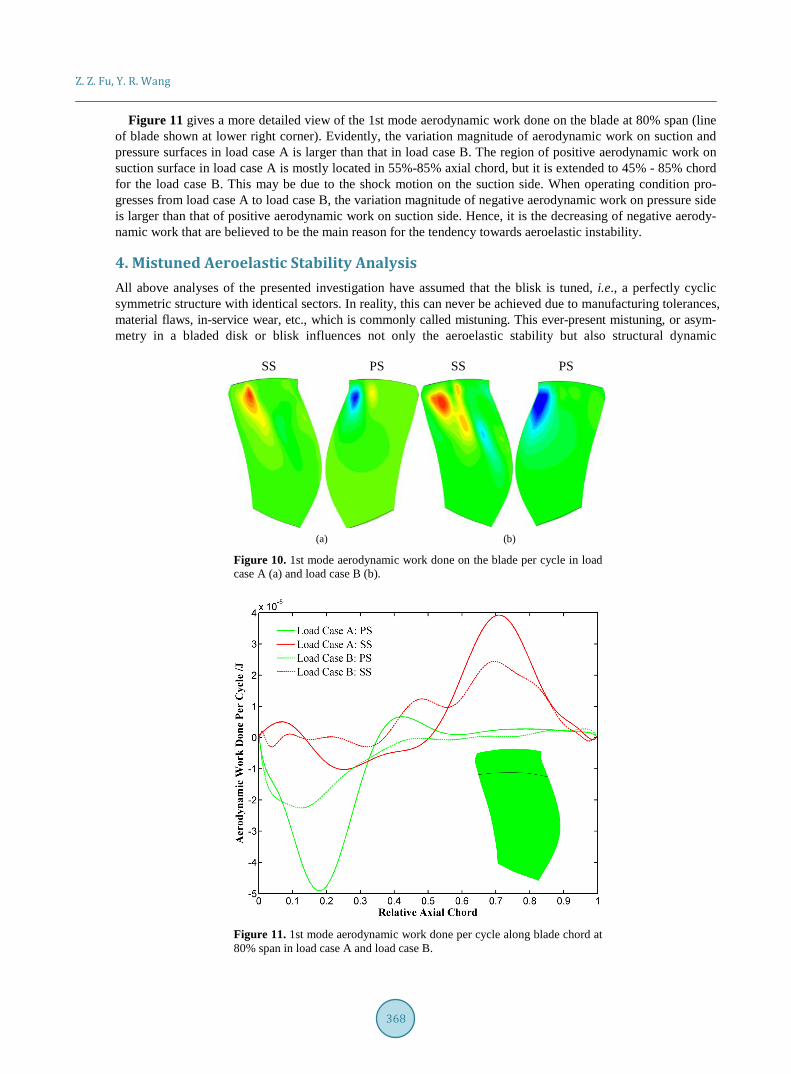
Figure 10 provides a comparison of distributions of 1st mode aerodynamic work done on the blade per airfoil oscillation cycle between two load cases. Red and blue colors signify positive and negative values respectively. Here, positive values imply that energy is fed into the airfoil (excitation) and negative values signify energy dis-sipation (damping). It can be observed that the blade part that absorbs the unsteady aerodynamic work is mostly located on suction surface and the negative region mainly locates on pressure surface on both operating condi-tions. Comparing Figure 8-10, it can be found that the region before shock position always corresponds to nega-tive aerodynamic work, showing stabilizing effects, and the region behind the shock corresponds almost directly to the positive aerodynamic work, showing destabilizing effects. Therefore, it can be concluded that the shock may be one of main reasons for flutter of fan blade.

Z. Z. Fu, Y. R. Wang
367
Figure 7. 1F mode aerodynamic modal damping ratio versus nodal diameter in load case A.
Figure 8. Steady state Mach number distributions at 80% span in load case A (a) and load case B (b).
Figure 9. Unsteady pressure amplitude distribution due to 1st mode in load case A (a) and load case B (b).
Z. Z. Fu, Y. R. Wang
368
Figure 11 gives a more detailed view of the 1st mode aerodynamic work done on the blade at 80% span (line of blade shown at lower right corner). Evidently, the variation magnitude of aerodynamic work on suction and pressure surfaces in load case A is larger than that in load case B. The region of positive aerodynamic work on suction surface in load case A is mostly located in 55%-85% axial chord, but it is extended to 45% - 85% chord for the load case B. This may be due to the shock motion on the suction side. When operating condition pro- gresses from load case A to load case B, the variation magnitude of negative aerodynamic work on pressure side is larger than that of positive aerodynamic work on suction side. Hence, it is the decreasing of negative aerody-namic work that are believed to be the main reason for the tendency towards aeroelastic instability.
4. Mistuned Aeroelastic Stability Analysis All above analyses of the presented investigation have assumed that the blisk is tuned, i.e., a perfectly cyclic symmetric structure with identical sectors. In reality, this can never be achieved due to manufacturing tolerances, material flaws, in-service wear, etc., which is commonly called mistuning. This ever-present mistuning, or asym- metry in a bladed disk or blisk influences not only the aeroelastic stability but also structural dynamic
SS PS SS PS
(a) (b)
Figure 10. 1st mode aerodynamic work done on the blade per cycle in load case A (a) and load case B (b).
Figure 11. 1st mode aerodynamic work done per cycle along blade chord at 80% span in load case A and load case B.
Z. Z. Fu, Y. R. Wang
369
behavior. In particular, it may lead to drastically increased forced response amplitude of the structure, but it has the potential to mitigate flutter risk. As mentioned in the introduction, it is well known that mistuning improves aeroelastic stability. The mechanism behind this is that mistuning leads to a mode localization which implies the participation of several and quite possible all tuned traveling wave modes in the motion. As a consequence the aerodynamic damping of mistuned system is always higher than the minimum one of tuned structure.
This mistuned aeroelastic analyses have been performed for 1st vibration mode in load case A through eigen-value analyses. The variation of blade mode shapes is assumed to be small when mistuning is introduced into system. Influence coefficient method has been employed to deal with unsteady aerodynamic forces. The details about influence coefficient method are not given in this paper but can be found in [4]. Unsteady analyses have been performed with all blade passages model in which only one blade oscillates with natural blade mode and frequency. The mistuning effects have been studied through the variation of imaginary part of eigenvalue which corresponds to the damping of system. A positive value of the minimum imaginary part of eigenvalue denotes that the system is aeroelastic stable. Here, the blade frequency has been chosen as mistuning parameter. When mistuning exists, the properties of each sector (or blade) of fan rotor are different. These differences may be represented by a way of individual blade mass, stiffness or shape, but all these differences would lead to distinc-tion of individual blade frequency. Alternate mistuning pattern has been chosen as intentional mistuning such that every second blade in the nominal (tuned) configuration is replaced by a higher-frequency blade.
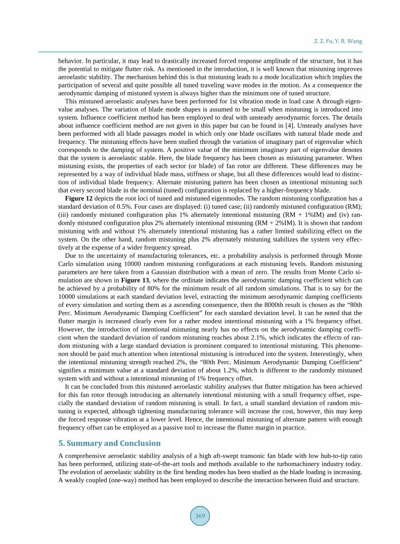
Figure 12 depicts the root loci of tuned and mistuned eigenmodes. The random mistuning configuration has a standard deviation of 0.5%. Four cases are displayed: (i) tuned case; (ii) randomly mistuned configuration (RM); (iii) randomly mistuned configuration plus 1% alternately intentional mistuning (RM + 1%IM) and (iv) ran-domly mistuned configuration plus 2% alternately intentional mistuning (RM + 2%IM). It is shown that random mistuning with and without 1% alternately intentional mistuning has a rather limited stabilizing effect on the system. On the other hand, random mistuning plus 2% alternately mistuning stabilizes the system very effec-tively at the expense of a wider frequency spread.
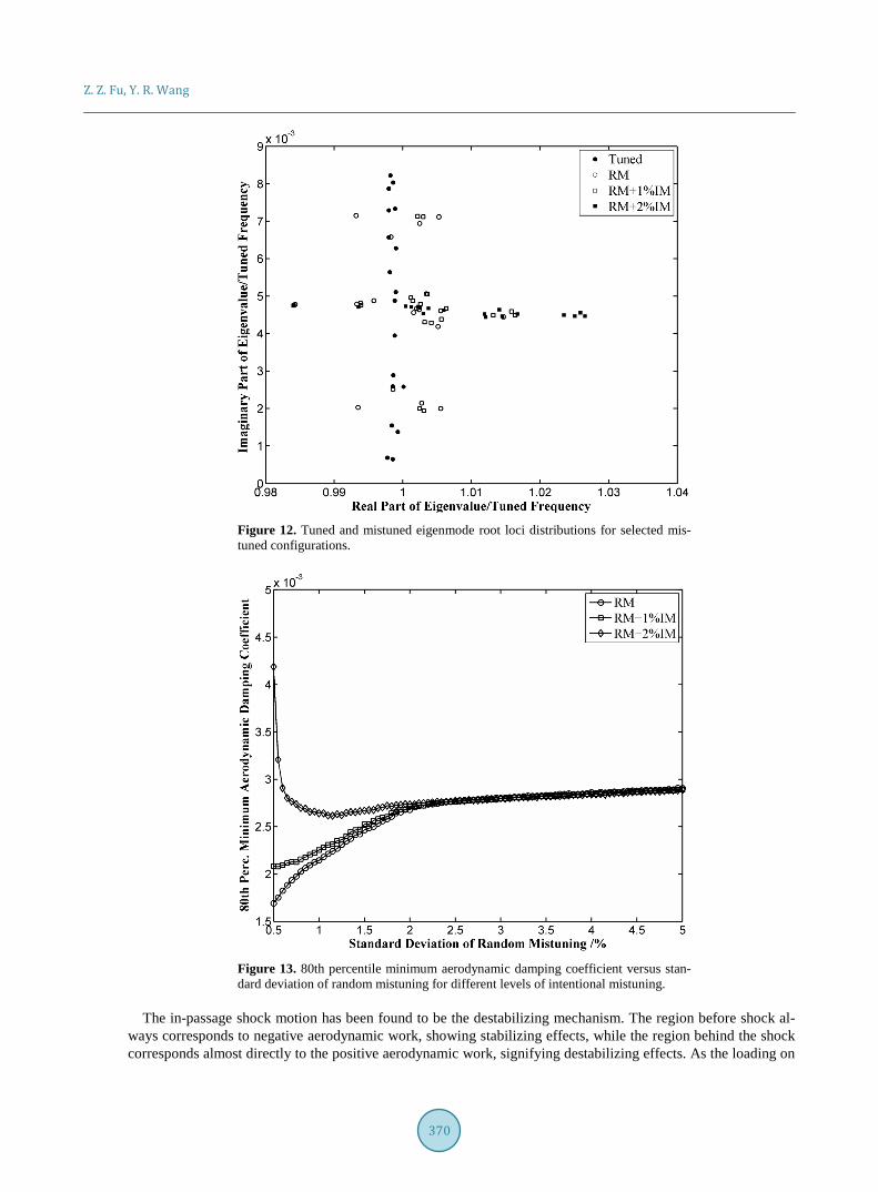
Due to the uncertainty of manufacturing tolerances, etc. a probability analysis is performed through Monte Carlo simulation using 10000 random mistuning configurations at each mistuning levels. Random mistuning parameters are here taken from a Gaussian distribution with a mean of zero. The results from Monte Carlo si-mulation are shown in Figure 13, where the ordinate indicates the aerodynamic damping coefficient which can be achieved by a probability of 80% for the minimum result of all random simulations. That is to say for the 10000 simulations at each standard deviation level, extracting the minimum aerodynamic damping coefficients of every simulation and sorting them as a ascending consequence, then the 8000th result is chosen as the “80th Perc. Minimum Aerodynamic Damping Coefficient” for each standard deviation level. It can be noted that the flutter margin is increased clearly even for a rather modest intentional mistuning with a 1% frequency offset. However, the introduction of intentional mistuning nearly has no effects on the aerodynamic damping coeffi-cient when the standard deviation of random mistuning reaches about 2.1%, which indicates the effects of ran-dom mistuning with a large standard deviation is prominent compared to intentional mistuning. This phenome-non should be paid much attention when intentional mistuning is introduced into the system. Interestingly, when the intentional mistuning strength reached 2%, the “80th Perc. Minimum Aerodynamic Damping Coefficient” signifies a minimum value at a standard deviation of about 1.2%, which is different to the randomly mistuned system with and without a intentional mistuning of 1% frequency offset.
It can be concluded from this mistuned aeroelastic stability analyses that flutter mitigation has been achieved for this fan rotor through introducing an alternately intentional mistuning with a small frequency offset, espe-cially the standard deviation of random mistuning is small. In fact, a small standard deviation of random mis-tuning is expected, although tightening manufacturing tolerance will increase the cost, however, this may keep the forced response vibration at a lower level. Hence, the intentional mistuning of alternate pattern with enough frequency offset can be employed as a passive tool to increase the flutter margin in practice.
5. Summary and Conclusion A comprehensive aeroelastic stability analysis of a high aft-swept transonic fan blade with low hub-to-tip ratio has been performed, utilizing state-of-the-art tools and methods available to the turbomachinery industry today. The evolution of aeroelastic stability in the first bending modes has been studied as the blade loading is increasing. A weakly coupled (one-way) method has been employed to describe the interaction between fluid and structure.
Z. Z. Fu, Y. R. Wang
370
Figure 12. Tuned and mistuned eigenmode root loci distributions for selected mis-tuned configurations.
Figure 13. 80th percentile minimum aerodynamic damping coefficient versus stan-dard deviation of random mistuning for different levels of intentional mistuning.
The in-passage shock motion has been found to be the destabilizing mechanism. The region before shock al-
ways corresponds to negative aerodynamic work, showing stabilizing effects, while the region behind the shock corresponds almost directly to the positive aerodynamic work, signifying destabilizing effects. As the loading on

Z. Z. Fu, Y. R. Wang
371
blade increases, the shock moves from blade trailing edge to leading edge. This behavior significantly changes the aerodynamic work done on the blade. The increasing of total positive aerodynamic work done on the blade surface is prominent to the dissipative (negative) aerodynamic work. It can be concluded that the energy flowing from blade to surrounding air is more and more difficult when the strength of in-passage shock increases.
Additionally, a statistical investigation of intentional and random mistuning has been performed through Monte Carlo simulation. Alternately intentional mistuning with enough frequency offset can stabilizes the ran-domly mistuned system very effectively. The introduction of intentional mistuning nearly has no effects on aerodynamic damping coefficient when the standard deviation of random mistuning reaches about 2.1%. There is an interesting phenomenon that a large amount intentional mistuning (for example 2%IM) is very sensitive to slight random mistuning. This needs to be investigated in the future.
Acknowledgements The authors wish to thank Xingmin Gui professor from Beihang University for his support for providing the knowledge about swept blade profile design.
References [1] Groth, P., Mårtensson, H. and Andersson, C. (2010) Design and Experimental Verification of Mistuning of a Super-
sonic Turbine Blisk. Journal of Turbomachinery, 132, Article ID: 011012. http://dx.doi.org/10.1115/1.3072492 [2] Zhai, Y., Bladh, R. and Dyverfeldt, G. (2012) Aeroelastic Stability Assessment of an Industrial Compressor Blade in-
cluding Mistuning Effects. Journal of Turbomachinery, 134, Article ID: 060903. http://dx.doi.org/10.1115/1.4007210 [3] Zhang, X.W., Wang, Y.R. and Xu, K.N. (2011) Flutter Prediction in Turbomachinery with Energy Method. Proc IM-
echE Part G. Journal of Aerospace Engineering, 225, 995-1002. [4] Hsu, K. and Hoyniak, D. (2011) A Fast Influence Coefficient Method for Linearized Flutter and Forced Response
Analysis. 49th AIAA Aerospace Sciences Meeting including the New Horizons Forum and Aerospace Exposition, Or-lando, 4-7 January 2011, 1-11. http://dx.doi.org/10.2514/6.2011-229
[5] Huang, X.Q., He, L. and Bell, D.L. (2009) Experimental and Computational Study of Oscillating Turbine Cascade and Influence of Part-Span Shrouds. Journal of Fluids Engineering, 131, Article ID: 051102. http://dx.doi.org/10.1115/1.3111254
[6] Hall, K.C., Kielb, R.E., Ekici, K., et al. (2005) Recent Advancements in Turbomachinery Aeroelastic Design Analysis. 43rd AIAA Aerospace Sciences Meeting and Exhibit, Reno, 10-13 January 2005, 1-23. http://dx.doi.org/10.2514/6.2005-14
[7] Kenyon, J.A. and Griffin, J.H. (2003) Experimental Demonstration of Maximum Mistuned Bladed Disk Forced Re-sponse. Journal of Turbomachinery, 125, 673-681. http://dx.doi.org/10.1115/1.1624847
[8] Lim, S.H., Bladh, R. and Castanier, M.P. (2007) Compact, Generalized Component Mode Mistuning Representation for Modeling Bladed Disk Vibration. AIAA Journal, 45, 2285-2298. http://dx.doi.org/10.2514/1.13172
[9] Petrov, E.P. (2011) Reduction of Forced Response Levels for Bladed Disks by Mistuning: Overview of the Phenome-non. Journal of Engineering for Gas Turbines and Power, 133, Article ID: 072501. http://dx.doi.org/10.1115/1.4002619
[10] Carta, F.O. (1967) Coupled Blade-Disk-Shroud Flutter Instabilities in Turbojet Engine Rotors. Journal of Engineering for Gas Turbines and Power, 89, 419-426. http://dx.doi.org/10.1115/1.3616708
[11] Sanders, A.J., Hassan, K.K. and Rabe, D.C. (2004) Experimental and Numerical Study of Stall Flutter in a Transonic Low-Aspect Ratio Fan Blisk. Journal of Turbomachinery, 126, 166-174. http://dx.doi.org/10.1115/1.1645532
[12] Bakhle, M.A., Thomas, J.P. and Reddy, T.S.R. (2008) Fan Flutter Computations Using the Harmonic Balance Method. 44th AIAA/ASME/SAE/ASEE Joint Propulsion Conference & Exhibit, Hartford, 21-23 July 2008, 1-7. http://dx.doi.org/10.2514/6.2008-4743
[13] Vasanthakumar, P. (2011) Computation of Aerodynamic Damping for Flutter Analysis of a Transonic Fan. Proceed-ings of ASME Turbo Expo 2011, GT2011, Vancouver, 6-10 June 2011, 1-9. http://dx.doi.org/10.1115/GT2011-46597
[14] McBean, I., Hourigan, K., Thompson, M., et al. (2005) Prediction of Flutter of Turbine Blades in a Transonic Annular Cascade. Journal of Fluids Engineering, 127, 1053-1058. http://dx.doi.org/10.1115/1.2060731
[15] Choi, Y.S., Gottfried, D.A. and Fleeter, S. (2010) Resonant Response of Mistuned Bladed Disks including Aerody-namic Damping Effects. Journal of Propulsion and Power, 26, 16-24. http://dx.doi.org/10.2514/1.36537
[16] Choi, Y.S., Lawless, P.B. and Fleeter, S. (2007) An Investigation of the Resonant Response of Mistuned IBRs. 43rd

Z. Z. Fu, Y. R. Wang
372
AIAA/ASME/SAE/ASEE Joint Propulsion Conference & Exhibit, 8-11 July 2007, 1-13. http://dx.doi.org/10.2514/6.2007-5036
[17] Avalos, J. and Mignolet, M.P. (2010) Maximum Amplification of Blade Response in Mistuned Multi Stage Assemblies. Proceedings of ASME Turbo Expo 2010: Power for Land, Sea and Air, GT2010, Glasgow, 14-18 June 2010, 1-14. http://dx.doi.org/10.1115/GT2010-23062
[18] Groth, P., Mårtensson, H. and Andersson, C. (2010) Design and Experimental Verification of Mistuning of a Super-sonic Turbine Blisk. Journal of Turbomachinery, 132, Article ID: 011012. http://dx.doi.org/10.1115/1.3072492
[19] Martel, C., Corral, R. and Llorens, J.M. (2008) Stability Increase of Aerodynamically Unstable Rotors Using Inten-tional Mistuning. Journal of Turbomachinery, 130, Article ID: 011006. http://dx.doi.org/10.1115/1.2720503
[20] Mayorca, M.A., Vogt, D.M., Mårtensson, H., et al. (2012) A New Reduced Order Modeling for Stability and Forced Response Analysis of Aero-Coupled Blades Considering Various Mode Families. Journal of Turbomachinery, 134, Article ID: 051008. http://dx.doi.org/10.1115/1.4003830
Nomenclatures AMDR: Aerodynamic Modal Damping Ratio IBPA: Inter-Blade Phase Angle IM: Intentional Mistuning Ma: Mach Number PS: Pressure Surface q: Modal Amplitude RM: Random Mistuning SS: Suction Surface W: Work per Cycle ω: Natural Frequency ζ: Modal Damping Ratio
Superscripts and Subscripts aero: Aerodynamic cfd: Fluid.