agenda - blackstone presentation.… · conventional assemblies • include the casing head, casing...
TRANSCRIPT


Agenda • Arrival/Welcome • Safety Orientation • Facility Tour • Presentation on Basic Wellhead and API Requirements • Lunch • Stack-up of MBU-LR Speed Head System/Conventional
Wellhead System/Overview of Frac Tree Equipment • Discussion | Q&A

Conventional Assemblies • Include the casing head, casing
hangers, spool sections, tubing head, tubing hanger, valves and fittings
• Provides safe and adequate means for supporting and attaching blowout control equipment during drilling
• Provides sealing between casing strings and a connection for the Christmas tree
• Requires manipulation of BOP’s with each added section
• Tubulars suspended on “slips”

Casing Heads
C2 Casing Head (With FPO’s)
C2-BP Casing Head (With Two Lockscrews)
C2 Casing Head (With LP Outlets and Baseplate)
Test Port
O-Ring Groove
Available with Threaded or Slip-on and Welded bottoms

Tubing Heads
CTH Tubing Head (With Secondary Bushing)
CTH Tubing Head (With integral bottom)
Test Port

Slip Type Casing Hangers
C1 Casing Hanger and H Plate. Non-Automatic slip-
type hanger. Used to suspend light to medium
casing loads in C2 & C2BP Casing Heads
C2 Casing Hanger. Standard automatic slip-type casing hanger. Used
to suspend medium casing loads (50% joint strength) in C2 & C2BP
Casing Heads
C9 Casing Hanger. Heavy duty automatic slip-type casing hanger. Used to suspend high casing loads in C9 & C9BP
Casing Heads

Mandrel Hangers
One Piece Mandrel Hanger Fluted Mandrel Hanger

Tubing Hangers and Tubing Head Adapters
CTH-2W wrap around hanger with BO2 coupling
and BO2 tubing head adapter
CTH-EN with EN tubing head adapter
T40 Hanger with T40 tubing head adapter
BPV Threads
BPV Threads
BPV Threads
CTH-2W

Multi-bowl Wellhead Systems
MBS MBU
11” 10M
11” 5M

Multi-bowl Wellhead Systems
MBU-T MBU-LR
Lock-Ring
Landing Ring
Threaded-on Flange
2” LP
3” LP
20” Casing
13-3/8” Casing
9-5/8” Casing 5-1/2” Casing

‘HPS’ Elastomer Secondary Seals
Springs in corners prevent extrusion
Large ID interference provides sealing on rough casing
Interference fit provides pressure energized seal. No plastic packing required.

Type ‘P’ Elastomer Seal
Metal retainer rings prevent extrusion
Seal energized against casing with plastic packing injection

‘Dovetail’ Elastomer Seals
Dovetail shape locks seal into groove
Wide seal surface provides improved sealing
Tapered edges help prevent extrusion
Commonly used as test plug and large O.D. seals

Type ‘S’ Elastomer Seal
Metal springs in corners to prevent extrusion
OD bump provides interference fit allowing seal to be pressure energized

Lockscrews
Integral Lockscrew Threaded Lockscrew

API Ring Gaskets
R Gasket 5,000 PSI
RX Gasket 5,000 PSI
BX Gasket 10,000-15,000 PSI

Frac Valve Comparison
• Two Seat Seal Rings • An Inner and Outer
Seal Ring That are Both Lip Sealed and Pressure and Spring Energized
DS-BSFC 7-1/16” 10M Valve CW FL-R 7-1/16” 10M Valve

Frac Valves
Detail of Seat with Seals
7-1/16” 10M
Detail of Seat with Seals
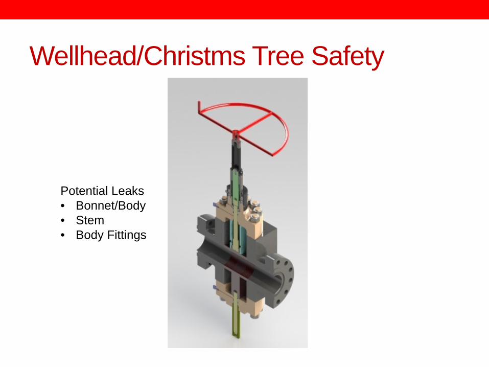
Potential Leaks • Bonnet/Body • Stem • Body Fittings
Wellhead/Christms Tree Safety

Wellhead/Christmas Tree Safety “Line of Fire”
• Test or injection fittings
• Lockscrews

Wellhead/Christmas Tree Safety Hidden Pressure

Wellhead/Christmas Tree Safety
One-Piece for lower pressures
Two-Piece for higher pressures

Wellhead/Christmas Tree Safety Back Pressure Valves

Wellhead/Christmas Tree Safety Body Fitting

API Flange Bolting • Flanges under pressure see a separation force equal to
the pressure times the area inside the ring gasket. F = P x A • This separation force is contained by the flange bolting.
Thus, larger flanges and higher pressure flanges have larger bolts and/or more bolts.
• As the bolt diameter increases the amount of make up torque goes up.
• API 6A publishes recommended make-up torques for API bolting.

f = 0.07 Xylan Coated f = 0.13 Standard Lubricant

Casing Effects During Frac
Initial Hanging Weight
Cold frac fluid causes casing to contract increasing load on slip
Pressure causes casing to balloon increasing load on slip
Top of cement
Suspension point in wellhead

Specification for Wellhead and Christmas Tree Equipment
• API Specification 6A • Twentieth Edition, October 2010
• ISO 10423:2009 (Modified), Petroleum and Natural Gas Industries- Drilling and Production
Equipment- Wellhead and Christmas Tree Equipment

API 6A Basic Contents 435 Pages
• Design and performance • Materials • Welding • Quality control • Equipment marking • Storing and shipping • Equipment specific requirements • Repair and remanufacture • Various Annexes covering purchasing guidelines, design,
testing, etc.

API 6A Product Specification What does it mean?
6A-U-EE-1.5-1-1
API Spec 6A Temperature
Class Material Class
PSL – Product Specification Level
PR – Performance Requirement

Temperature Class • Determined by the maximum flowing temperature in the wellhead or the mud circulating temperature and the minimum seasonal external temperature.
• API Designations o K ………… -750F to 1800F o L ………… -500F to 1800F o N ……….. -500F to 1400F o P ………… -200F to 1800F o S ………… 00F to 1400F o T ………… 00F to 1800F o U ………… 00F to 2500F o V ………… 350F to 2500F o X ………… 00F to 3500F* o Y ………… 00F to 6500F*
* Non-standard Ratings

Material Class 0 to < 0.05
psia 0.05 to 0.5
psia > 0.5 to 1.5
psia > 1.5 psia
0 to < 7 psia
AA Non-sour
Non-corrosive
EE-0.5 or DD-0.5 Sour
Non-corrosive
EE-1.5 or DD-1.5 Sour
Non-corrosive
EE-NL or DD-NL Sour
Non-corrosive
7 to 30 psia
BB Non-sour
Slightly Corrosive
EE-0.5 Sour
Slightly Corrosive
EE-1.5 Sour
Slightly Corrosive
EE-NL Sour
Slightly Corrosive
> 30 to < 200 psia
CC Non-sour
Moderate to Highly Corrosive
FF-0.5 Sour
Moderate to Highly Corrosive
FF-1.5 Sour
Moderate to Highly Corrosive
FF-NL Sour
Moderate to Highly Corrosive
> 200 psia
CC or HH Non-sour
Highly Corrosive
FF-0.5 or HH-0.5 Sour
Highly Corrosive
FF-1.5 or HH-1.5 Sour
Highly Corrosive
FF-NL or HH-NL Sour
Highly Corrosive
H2S Partial Pressure
CO
2 Par
tial P
ress
ure

Product Specification Level (PSL) • PSL 1, PSL2, PSL3, PSL3G, PSL4 • Quality control requirements such as material certifications, NDE, etc. that increase with the severity of service.
• API 6A Annex A provides purchasing guidelines for selecting the proper PSL of Primary Equipment oTubing Heads oTubing Hangers oTubing Head Adapters oLower Master Valves


Performance Requirement (PR) • Cycle testing of the designs • Cycles may include pressure, loads, open-close, etc.
depending on product being tested • PR1 is minimum API cycle requirements found in the
equipment section of the Specification 6A • PR2 adds additional cycles

Standard Materials for API 6A Materials Classification
Material Class Body, End and Outlet Connections
Mandrel Hangers Bull Plugs, Valve Removal Plugs and Back-Pressure
Valves 2K, 5K, 10K 15K
AA 4130 60K (CMS-102)
4130 75K (CMS-103)
4140 110K (CMS-106)
BB 4130 60K (CMS-102)
4130 75K (CMS-103)
17-4 PH (CMS-303)
CC 410SS (CMS-301)
410SS (CMS-301)
17-4 PH (CMS-303)
DD 4130 60K (CMS-102)
4130 75K (CMS-103)
4130 80K (CMS-104)
Or 4140 80K
(CMS-105)
4130 60K (CMS-102)
EE-XX 4130 60K (CMS-102)
4130 75K (CMS-103)
FF-XX 410SS (CMS-301)
410SS (CMS-301)
17-4 PH (CMS-303)
Or Inconel 718 (CMS-304)
HH-XX ------ ------ Inconel 718 (CMS-304)

Product Plan - Quality Control Requirements for Wellhead Bodies and Assemblies
The following chart details the Quality Control Requirements for all bodies. Applies to Casing and Tubing Heads, Cross-Over Connectors, Tubing Head Adapters, Top Connectors Tees and Crosses, Adapter and Spacer Spools, Casing and Tubing Hangers, Flanged Connectors Threaded Connectors, Other End Connectors.
Parameter PSL 1 PSL2 PSL3 Comments
Tensile Testing CMS-002 and Material Spec
CMS-002 and Material Spec
CMS-002 and Material Spec Compare MTR to Material Spec
Impact Testing CMS-004 CMS-004 CMS-004 Section 8.0 & EPS
Compare MTR to Material Spec
Chemical Testing CMS-002 and Material Spec
CMS-002 and Material Spec
CMS-002 and Material Spec Compare MTR to Material Spec
Hardness Testing CIR-002 CIR-002 CIR-002 Process Router & EPS
Dimensional CIR-001 CIR-001 CIR-001 Process Router & EPS
Thread Gauging CIR-004 or
TTM-WI-7.5.1
CIR-004 or
TTM-WI-7.5.1
CIR-004 or
TTM-WI-7.5.1 End and Outlet Connection Threads Gauge 100%
Traceability Heat Traceable Heat Traceable Heat Traceable & Heat Lot
PSL-1/2-Trace by heat numbers PSL-3-Trace by serial numbers
Visual Exam CIR-003 CIR-003 ---
Surface NDE --- CNT-002 or
CNT-004
CNT-002 or
CNT-004 Process Router & EPS
Volumetric NDE --- --- CNT-005 Prior to Machining
Weld NDE --- CNT-008 CNT-008 Process Router & EPS, if applicable
Marking MD Drawing MD Drawing MD Drawing Process Router & EPS
Serialization --- --- Each component Work Order-sequential number
Hydrostatic Test CTS-001 CTS-001 CTS-001 PSL-3 – Chart Recorder Required
Assembly Traceability CTS-001 CTS-001 CTS-001
PSL-1/2- Record heat number of body
PSL 3- Record heat and serial number
Set Out Reports
Assembly Serialization --- Work Order-sequential number
Work Order-sequential number Process Router
API Monogram TTM-MSP-A-1 TTM-MSP-A-1 TTM-MSP-A-1 Process Router & EPS

Impact Testing
Temperature
Minimum Average Impact Value Transverse Direction - Ft-Lb (J)
Classification Test PSL 1 PSL 2 PSL 3
K -75 (-60) 15 (20) 15 (20) 15 (20)
L and N* -50 (-46) 15 (20) 15 (20) 15 (20)
P -20 (-29) -- 15 (20) 15 (20)
S 0 (-18) -- -- 15 (20)
T 0 (-18) -- -- 15 (20)
U 0 (-18) -- -- 15 (20)
V 0 (-18) -- -- 15 (20)

Cactus Record Requirements Bodies, End and Outlet Connections, Mandrel Tubing Hanger and Casing
Hanger PSL-1 PSL-2 PSL-3*
Material Test Reports: Chemical analysis, tensile test, impact test (if required) and hardness test
X X X
Weld Process Records: WPS, WPQR and WQR X X X
Welding Process Records: Welder identification, weld procedures, filler material type, post-weld heat treatments
X
NDE personnel Qualification Records for Weld Metal Corrosion Overlay on Bodies X X X
Hardness Test X X Actual Hardness
Dimensional Inspection X NDE Records: Surface NDE, Weld Volumetric NDE, and Repair Weld NDE X X
Volumetric NDE X Heat Treatment COC X X
Non-Metallic Seals PSL-1 PSL-2 PSL-3
Batch Traceability, Cure date certification, Shelf-life expiration date certification X
Bullplugs, Valve-Removal Plugs and Back-Pressure Valves
Material Test Reports : Chemical analysis, tensile test, impact test, and hardness test
Assembled Equipment Records PSL-1 PSL-2 PSL-3*
Pressure Test Records: Actual test pressure, holding period duration X X
Pressure Test Records: Hydrostatic Test Chart X
Assembly Traceability Record X
*All required records for PSL3 components & assemblies shall reference the specific part serial number.

Records to be Furnished to Customer Bodies, End and Outlet Connections, Mandrel Tubing Hanger and Casing
Hanger PSL-1 PSL-2 PSL-3*
No records are required -- -- --
Non-Metallic Seals PSL-1 PSL-2 PSL-3
No records are required -- -- --
Assembled Equipment Records PSL-1 PSL-2 PSL-3*
Certificate of Compliance – stating that equipment conforms to PSL 3 of API Spec 6A and the temperature and material class
-- -- X
Pressure Test Records: Actual test pressure, holding period duration -- -- X
Pressure Test Records: Hydrostatic Test Chart
-- -- X
Assembly Traceability Record -- -- X