agent technology applied to information systems
TRANSCRIPT

DOTTORATO DI RICERCA IN INGEGNERIA INFORMATICAXVII CICLO
Sede Amministrativa Università degli Studi di Modena e Reggio Emilia
TESI PER IL CONSEGUIMENTO DEL TITOLO DI DOTTORE DI RICERCA
AGENT TECHNOLOGY APPLIED TO INFORMATION SYSTEMS
CANDIDATO Gionata Gelati


To my friends Gianni and Meris


ACKNOWLEDGEMENTSThanks to the database group of the University of Modena and Reggio Emilia.


TABLE OF CONTENTS 1 INTRODUCTION 1
Part I - Sofware agents and agent technology
2 SOFTWARE AGENTS 4 2.1 Defining software agents 5 2.2 Software agents vs. software objects 7 2.3 Agents vs Services 10
3 PERFORMING AGENT DESIGN 11 3.1 Background 12 3.2 Class diagrams 15 3.3 Behaviours 21 3.4 Behavioral matching 23 3.5 Interactional view 24
3.5.1 Background 25 3.5.2 Agent UML 27
3.6 Sequence diagrams 28 3.7 Experiencing AUML sequence diagrams 33
3.7.1 Sending messages to more than one agent 34 3.7.2 Trigger management 37 3.7.3 Atomic transactions 37
3.8 Comparison with previous AUML proposals 39 3.9 Conclusions 40
4 ARCHITECTING AGENT SYSTEMS 42 4.1 An abstract infrastructure model 43 4.2 FIPA: a standard model for MAS infrastructures 47
4.2.1 The directory facilitator 49 4.2.2 The agent management system 50 4.2.3 The message transport service 50
4.3 JADE 53 4.3.1 The JADE agent platform 54 4.3.2 The JADE agent model 55 4.3.3 The JADE Kernel 58 4.3.4 Persistence 61 4.3.5 JESS 62 4.3.6 JADE-S: security for multi-agent systems 63
Part II - Applying agent technology to information systems
5 WINK: WEB-LINKED INTEGRATION OF NETWORK-BASED KNOWLEDGE 67 5.1 Project motivation 67 5.2 Case study 69 5.3 Architecture 70 5.4 Overview of the Project Collaboration Portal 72 5.5 The integration framework 73
5.5.1 Information integration 73 5.5.2 Query processing 78
6 THE SEWASIE MULTI-AGENT SYSTEM: MANAGING A NETWORK OF MEDIATORS 85 6.1 The SEWASIE system architecture 87 6.2 The SEWASIE multi-agent platform 89
6.2.1 Coordinating agents: protocols and final state machine behaviors 90 6.2.2 Fault tolerance 91
6.3 The SEWASIE agents 95 6.4 Semantic brokering: the brokering agent 95
6.4.1 Gluing SINodes 96 6.4.2 Query decomposition 97 6.4.3 Query expansion 99

6.4.4 Query unfolding 100 6.4.5 Brokering agents as final state machines 102
6.5 Query Agent 106 6.6 SINode Agents 106
6.6.1 The Java GUI model and JADE GUIs 107 6.6.2 SEWASIE shadow agents 108
Part III - Software agents in e-commerce
7 SOFTWARE AGENTS IN VIRTUAL SOCIETIES 110 7.1 Approach 111 7.2 Basic concepts 112 7.3 Actions and obligations 115 7.4 The counts-as link 119
7.4.1 Jones and Sergot's analysis 119 7.4.2 A new proposal 120 7.4.3 A comparison 122
7.5 Proclamation and declarative power 124 7.5.1 The notion of proclaiming 124 7.5.2 Hierarchy among agents 128 7.5.3 Empowering autonomous agents 130
7.6 The framework applied to the contract net protocol 136 7.7 Future developments: applications and computational issues 139
Conclusions 142Bibliography 144

1
1. INTRODUCTION
Software agents represent the ultimate idea of artificial intelligence. For many years
now computer engineers and scientists have drawn attention to define how software
agents may be useful for tackling issues concerning intelligent and pervasive computer
systems. Despite the soundness of the theoretical results presented in literature,
software agents have not yet entered mainstream technology.
Some share the belief that there basically exists a lack of tools intended to sup-
port designers and programmers in building systems based on software agents. This
inspired the present work and brought to a less theoretical and more practical ap-
proach to the topic because of the urgency of providing tools and experiences of
applied agent technology.
The thesis is thus divided into three parts. In the first one, software agents are
presented and critically compared to other mainstream technologies. We also discuss
modeling issues. In the second part, some example systems where we applied agent
technology are presented and the solution is discussed. The realistic scenarios and
requirements for the systems were provided by the WINK and SEWASIE projects.
The third part presents a logical framework for characterizing the interaction of
software agents in virtual societies where they may act as representatives of humans.
The contribution of the thesis has been twofold. First, facing the problem of
implementing systems, we started to define tools through which agent technology
could be effectively applied. This has been the case for instance for Agent UML
and the logical framework presented in chapter 6. Second, we adopted technologies
developed by others and this served as testing activity for ongoing efforts. It is the
case of JADE, the Java Agent Development Environment, developed by Telecom

2
Italia Lab located in Turin, that was used to implement the multi-agent systems for
the WINK and SEWASIE projects.

Part I
Sofware agents and agent
technology
3

4
2. SOFTWARE AGENTS
The concept of agent represents a milestone in the thinking of computer science. The
genesis of such a concept can be tracked down to a number of disciplines among which
a prominent contribution has been derived from artificial intelligence. Agents are
basically intelligent entities. Intelligent as they show behaviors in which they make
rational choices. Entities as they are artifact of human endeavor. We distinguish
two coarse categories of agents. The first one comprises robots, intended as entities
having an hardware body and executing in the real world. The second comprises
software agents, the purely software counterpart of robots. The main dissimilarity
between the two concerns the environment they experience, how they sense it and
what actions they can undertake to change the state of the environment. On one
side we have a physical world with its mechanical laws, on the other a logical one,
built on top of operating systems and networks. Usually to build robots we have to
solve problems like vision, motion control, live speech, physical sensing and human-
like interfaces. To program software agents, we need visual interfaces, distributed
computer architectures and IT security. Both have to face issues such as high-
level communication, distributed planning, cooperation and negotiation, though they
may find different forms of application. The commonality is that both pull towards
making a system (no matter if hardware or software or hybrid) more intelligent,
more suitable to serve human or human-like purposes. With this respect they are
complementary to the goal of producing artificial intelligent artifacts: these artifacts
will have two dimensions, one related to their physical presence in the world, the
other related to the exploitation of the advantages an infrastructure such as computer
networks offers. We will focus here on software agents.

5
2.1 Defining software agents
As they are the object of the present work, we will give a characterization of
their properties. The need for a specification arises from the fact that, being agents
and software agents one of the main objects of study of artificial intelligence, as AI
has become more and more interdisciplinary, agents have been applied to a wide
spectrum of fields, assuming from time to time slightly different connotations. At
present, there is no commonly accepted definition of agent, although many share
some points.
In [RN03], a classical reading in AI, the authors define an agent as an “entity that
perceives and acts”, “a function from percept histories to actions”. On the same line
of discourse is the definition by Hayes-Roth [HR95], “intelligent agents continuously
perform three functions: perception of dynamic conditions in the environment; action
to affect conditions in the environment; and reasoning to interpret perceptions, solve
problems, draw interfaces, and determine actions”.
The most evident feature of agents lies in that they are supposed to activate
their capabilities (reasoning or acting for instance), i.e. to act without the control of
external entities [Mae95,OPB00]. Upon request, they can deny execution or, even
in the case no external request has arrived, they can undertake actions. Autonomy
appears thus as a key feature of agents. The concept can be approached by different
perspectives.
We can take for instance a knowledge perspective. In [RN03], the authors state
that “[a rational agent] should learn what it can to compensate for partial or incorrect
prior knowledge”. This view encompasses that, when built, an agent is provided with
some knowledge and the capability to evolve it, learning from its experience. The
agent will then refine its knowledge and, at a certain time in its life, it may even
have deeply changed its behaviour, so that we can hardly find any hint of the original
behavior. If this is the case, the agent’s knowledge has become “independent” from
its original state. This view emphasizes how agents reason about things. The actions

6
of the agent can be even decided by an external entity, but how it executes them
is not directly controllable, responding to an internal, possibly intelligent thread of
control. The result is that such agents can become flexible enough to face the different
situations that can happen in their environment. An example is represented by an
expert system which provides on-demand medical consultancy, whose knowledge
grows as cases are faced and whose decision-making algorithms varies according to
the patient’s medical history.
Numerous contributions seem to consider autonomy under a different light, that
of deliberative choice of actions. The agent, once activated and initially instructed,
has its own thread of control and can decide if an action has to be undertaken by
itself. The focus here is on what the agent does. Typically, an agent is assigned an
overall goal in a declarative way and it can decompose it into a hierarchy of sub-goals
and finally actions. It is the agent that has the last word in choosing which actions
are supposed to conduct to the best possible result, it is the agent that knows (or
reasons about) when to undertake them and if other partners (agents) have to be
involved. An example of such a system is an house alarm system, which responds
according to the geometry and the physical conditions of the environment, but also
in response to intruders’ moves.
Again, autonomy can be seen as deriving from internal motivation. A motivation
is any desire or preference that can lead to the generation and adoptions of goals
and which affects the outcome of the reasoning or behavioral task intended to sat-
isfy those goals [Ld95, dL96]. We classify agents as having goals and autonomous
agents as having goals totally or partially generated under the influence of internal
motivations. As Luck and D’Inverno put it, “motivations are not-derivative and
governed by internal inaccessible rules, while goals are derivative and relate directly
to motivations”.
Further perspectives on autonomy have been presented in [Pit04a,Pit04b]. The
authors give a characterization of agents’ autonomy in terms of a relational concept,
how agents are interrelated or correlated with each other (it is typical of social

7
sciences to consider agents both artificial and human entities, as in the work of
Castelfranchi). They then distinguish between social autonomy (or autonomy from
other agents) and non-social autonomy (or autonomy from the environment).
Collecting these ideas, we can observe that in order to build agents which are in
some way autonomous, we need to design agents which show a degree of intelligence.
In literature we distinguish three degrees of intelligence: reactivity, that is the ability
to react to external inputs, pro-activeness that is the ability to undertake actions and
finally the capability of learning. Learning is the highest expression of intelligence
as it allows agents to evolve over time, adapting their behavior by verifying the
conditions of the environment and the results of their actions.
2.2 Software agents vs. software objects
“Is it an object or an agent?” is a popular question in the agent community
[FG97]. As often happens, answers much depend on the assumptions we made. The
following lines are an attempt to make things less confusing.
Software objects are instances of classes. Classes represent abstract data types,
with their data structures and methods that work on them. Booch writes that “An
object has state, behavior and identity” [Boo94]. The state is represented by the
variables defined for that class of objects, the behavior is given by the methods and
the identity is unique within the local execution environment.
Software agents represent objects with enhanced capabilities, or “active objects,
exhibiting both dynamic autonomy (the ability to initiate action without external
invocation) and deterministic autonomy (the ability to refuse or modify an external
request)” [OPB00]. They are based on the same concepts, applied to a wider range:
their state is not only produced by internal computation but also by perceiving
external conditions, their behavior results from more complex considerations than
method execution, messages are not simple method invocations, but are true high-

8
level messages [FFMM94,New82] with a performative, a well-defined semantics and
possibly follow an interaction protocol.
The internal state of an agent is represented by the set of properties that identify
its status, the snapshot at a certain time of the state of its evolution. It is usually
accessible only to the agent itself and is used to reason about the facts (actions and
conditions) the agent is able to consider. A purely reactive agent does not hold an
internal state, as the choice of what to do next is based only on the latest percept
input received. Having an internal state is the enabling factor that brings an agent
from purely reactive to more sophisticated behavior. Objects resemble to purely
reactive agents, where the environment is the execution environment and the only
perceivable external events are method calls. Each method call than fires exactly the
execution of the method with the specified name. We cannot of course claim that
having a state is a fully distinctive feature of agents. Each piece of software can be
conceived to hold variables that it uses to carry out its computation. Nevertheless,
whilst we commonly use variables to store values that are produced internally, the
internal state of an agent may derive from external inputs, from what it senses of
the environment external to it.
Object systems are implicitly meant to execute on the top of an operating system
and an execution environment (sometimes also a virtual machine). More and more
frequently applications expose their services over a network. With software agents
the presence of the environment is more explicit, as they observe it and the collected
information may impact on the way agents will reason in the future. The environ-
ment becomes an active component of the system, a far more complex entity than
a mere execution environment. As such it requires to be explicitly modeled in the
agent knowledge. For this reason, we say agents are situated. They are expressively
designed to operate in a specific environment. Sometimes a dramatic change of the
environment will not allow an agent to execute appropriately or at all. It is the case,
for instance, of a mobile robot with a camera, which is suddenly out in a dark room.
9
Building agents means indeed finding the best performing agent for the environment
it must operate in [RN03].
The concept of software agents is thus an extension of the concept of objects,
perhaps realizing in its full the potential of the object paradigm. In the same way
the definition of an object is the ground for defining the object-oriented software
paradigm, so does the definition of agent for the agent-oriented paradigm. What
appears to be different to one approaching the field is that while the object-oriented
movement has produced object-oriented languages and compilers, the agent-oriented
has not. And it was never the intention of the proposal, as agents stress upon
features of objects that are usually underestimated in object-oriented systems. We
can say that the object-oriented way of designing producing results in using the most
straightforward elements of objects, while agent-oriented proposes a paradigm where
designers are forced to consider more advanced features of objects in order to build
complex systems. As the authors of [RN03] put it, “the notion of agent is meant
to be a tool for analyzing systems, not an absolute characterization that divides
the world into agents and non-agents”. This also explains why the most widely
used agent toolkits are built using object-oriented languages, this being evidently no
contradiction.
Nevertheless, we still like to distinguish between objects and agents. We will
consider a software component as a software agent whenever it is characterized by
a sufficiently significant internal state, a sensing activity possibly impacting on the
internal state, a reasoning activity which makes the component choose the actions to
undertake (or whether an action has to be undertaken at all) [WJK00] and high-level
communication through speech-acts [Aus62,Sea69]. Having at disposal these features
presupposes an underlying architecture that is more complex than the bare facilities
provided by an operating system and an execution environment. We will discuss the
software architecture needed by agent systems in Chapter 4.

10
2.3 Agents vs Services
Services in a service oriented-architecture may closely resemble to software agents.
A service-oriented architecture is essentially a collection of services which interact
with each other. Interacting could imply either simple data passing or a coordination
process involving two or more services. A service is a function that is well-defined,
self-contained, and does not depend on the context or state of other services. Nowa-
days the technology of web services is the most used to realize such architectures.
According to the W3C [Con], “a web service is a software system designed to support
interoperable machine-to-machine interaction over a network. It has an interface de-
scribed in a machine-processable format (specifically WSDL). Other systems interact
with the web service in a manner prescribed by its description using SOAP messages,
typically conveyed using HTTP with an XML serialization in conjunction with other
web-related standards.”
A first account on the difference between agents and services is given by the
W3C itself: “A web service is an abstract notion that must be implemented by a
concrete agent. The agent is the concrete piece of software or hardware that sends
and receives messages, while the service is the resource characterized by the abstract
set of functionality that is provided”.
Other differences may be found. Web services are way to use a server-based
system.Web services run as background processes of an application server and as
such are fully controllable. They do not hold a proper autonomy.
Further, both agents and services are meant to build interoperable systems.
While agent solve the matter using high-level communication with speech-acts [Aus62,
Sea69], services relies on standard interfaces like WSDL to specify how remote meth-
ods invocations can be performed.

11
3. PERFORMING AGENT DESIGNING
The characterization given in the previous chapter covers the definition of software
agents, highlighting their qualitative features. Qualitative features are good to give
a general idea of the technology but are insufficient for a software designer who
wants to include agents in a system. This can also be seen as one reason why
agent-based systems have not yet entered mainstream industrial applications, despite
during the last decade a high number of theories, models, agent toolkits and design
methodologies have been proposed. A qualitative approach should be backed up by
more tangible tools that allow the actual development of agent-based systems. We
share the view proposed in [BMO00] that, in order to be more widely adopted, we
have to present agents as an extension of existing knowledge and practices.
Practices in the field of software design are mainly related to object-oriented
software design and development, which relies on well-established and trusted meth-
ods. One of these is the Unified Modeling Language (UML) [Boo94], a widely
accepted notation for designing software systems according to the object-oriented
paradigm. The view of software as the next step beyond objects has lead to ex-
plore extensions to UML to accommodate the distinctive requirements of software
agents [BMO00]. In [OPB00, BMO00, Bau02, Hug02a, Hug02b, Mod03b, Mod03a]
ideas were progressively refined around the specification of an Agent Unified Model-
ing Language (AUML). The quality of these efforts have brought the Foundation of
Intelligent Physical Agents [fIPA] and the Object Management Group [Gro] to form
an interest group to complete the AUML specification.
As the work on AUML specification is still on-going, we present here the ideas
developed so far, resulting from previous work and draft specifications, together with
extensions we find useful for modeling software agents [Ber].

12
3.1 Background
Research on agent-based software development has been a very important dis-
cipline for agent technology. In the last few years a number of methods have been
proposed to the scientific community. The first approaches are surveyed in [IGG99].
Some more recent methodologies are interesting to understand what are the main
issues to worry about when approaching the design of a multi-agent system.
The Gaia methodology [WJK00] proposes to break the process in an analysis
stage and a design stage. In both stages, designers are required to deal with models
(roles model and interaction model for the analysis stage and agent model, services
model and acquaintance model for the design stage). This way, designers and devel-
opers are progressively guided through specifying more and more details about the
application and the system, being encouraged to follow a process based on organi-
zational design.
The Tropos methodology [MKC01] is based on two features: the notions of agent,
goal, plan and other agent related concepts are coherently used throughout the pro-
cess and requirements analysis and specification are an essential part of the method-
ology. At the core of the methodology there is the Tropos Modeling Language which
is based on a meta model and is conceived as an extensible language.
Commonalities between the two methodologies are:
• they distinguish a conceptual and an implementation or development phase
during the overall process;
• they use different models to catch different views of the system-to-be. These
views concerns the following aspects of agent hood: agents, environments,
interactions and organizations;
• they support not only agent-based systems, but are aware that real applications
envisage a blend of object-oriented services and agent technology.

13
It follow that in order to provide a comprehensive view of a system involving
agents we have to specify facts about the architecture of agents and their features,
the interactions that can happen among them, the environment that supports their
execution and how they can (be) organize(d) as a community. We have four views:
the agency view, which deals with agents knowledge, belief, intentions, plans and be-
haviors; the environmental view, which models how agents react to external changes;
the interaction view, where interaction protocols are specified; the organizational
view, which gives details on organizations to which an agent belongs. In order to
fulfill its unification purpose, AUML should provide a sufficiently rich notation to
support these views. AUML as unified modeling language should thus aim at cov-
ering both the conceptual and the implementation level of systems’ design. The
conceptual level of design is intended to provide an overview of the system, repre-
senting the different agents and classes that compose it and the relationships inter
curring among these entities.
The first move towards the definition of Agent UML class diagrams has been done
by Bauer [Bau02]. According to Bauer an agent can be divided into three parts: a
communicator, carrying out the physical communication, a head, dealing with goals
and states, and a body, performing the actions of the agent. Bauer’s approach gives
rise to a class diagram as the one depicted in Figure 3.1, where Bauer considers the
following information:
• agents and roles: an agent role identifies a set of agents satisfying distinguished
properties, interfaces, service descriptions or having a distinguished behavior;
• state description: it is a logical description of the state using well formed
formula which can be expressed in whatever logic we choose;
• actions: agents can perform two types of actions. Pro-active actions are trig-
gered by the agent itself. Re-active actions are triggered by another agent. An
agent action is defined by its signature toghter with pre- and post-conditions,
effects and invariants;

14
Fig. 3.1. Bauer’s approach to AUML class diagrams
• methods: similar to UML methods;
• capabilities, service description and supported protocols: capabilities, services
and protocols are described in an informal way. Capabilities may be alterna-
tively rendered by object-oriented class diagrams;
• constraints and society: the constraints to enter or leave societies of agents;
• agent head automata: the behavior of the agents head has to be specified in
the agent head automata. The automata defines the re-active behavior of the
agent, relating the incoming messages with the internal state, actions, methods
and the outgoing messages. it also defines the pro-active behavior, triggering
different actions, methods and state-changes depending on the internal state
of the agent.

15
These concepts have been critically revised and extended by Huget in [Hug02a].
Similarities between the two approaches are to be found in the way they consider
actions as reactive and proactive (Huget’s internal actions are Bauer’s methods),
capabilities and protocols (Huget adds the information on role, as an agent can
play more roles given a protocol). According to Huget himself, the main difference
between his approach and Bauer’s lies in the use of the agent head automata. Bauer’s
head automata are meant to model information related to communicative acts and
the impact they have on the activity of an agent. We agree with Huget in that head
automata capture a part of agent dynamic behavior and should not belong to a static
view of the system. We should rather use sequence or activity diagrams to model
the dynamic and interactive aspects of the agent project. A second difference is how
the two consider the description of the state of an agent. Bauer’s state description is
for the computation of beliefs, desires, intentions and goals as well-formed formulas.
Huget considers instead these elements as objects linked to an agent. In this way
it is easier to retrieve, merge and modify the state of an agent. Further, as they
are objects, they are external to an agent and can be easily shared among a group
of agents. A third difference is in the modeling of organizations. With respect to
Bauer, Huget adds the notion of role and the conditions by which the agent can
enter, stay in and leave a particular organization.
3.2 Class diagrams
UML class diagrams are intended to capture the static architecture of the system,
a graphic view of the static structural model. They collect elements such as classes,
interfaces and the relationships among them. Classes and interfaces are characterized
by having an header, whose value is the name of the class, a set of variables and a
set of operations as depicted in Fig. 3.2. Interfaces have a similar representation.
The relationships between two static elements classes can be of four types (Figure
3.3):

16
Fig. 3.2. The notation for a class in UML

17
• association: there is an association whenever two classes are generically con-
nected. It is the case of the class Dog and the class Owner. Multiplicity can
be specified at both ends. Possible values are n, (n,m) and (n, ∗) with n < m,
n, m ∈ ℵ. To help readability we may add an arrow to assign a direction to
the association;
• generalization: there is generalization when a general class (called parent) ab-
stracts the features of more specific classes (called children). If more classes are
abstracted, then the general class models their common features, i.e. children
inherit all of the properties of the father. It is otherwise named “is-a” relation-
ship. An example is given by classes Car, Spider and Coupe. Constraints may
specify whether an instance of the general class can be mapped to only one or
to more specialized classes (overlapping versus disjoint) or whether an instance
may belong to a non-listed child (complete vs. incomplete). It is represented
by a solid line with a triangle where it meets the more general element;
• aggregation: there is aggregation whenever a class is formed as a collection
of other classes. It is a “whole/part” relationship. It is the case of class
RoomFurniture and class Table. Aggregation is represented by a solid line with
a diamond near the aggregate class. A variation is the composition relationship
that indicates that one instance of a part element belongs only to one instance
of the formed element. It can be the case of the class Bicycle and the classes
Wheel, Brake and Frame. For composition, the arrowhead is filled;
• dependency: a dependency represents a semantic relationship between two
elements. It indicates a situation in which a change to the target element may
imply a change to the source element and not vice-versa. It is the case of class
Agenda and the class Meeting. It is represented as a dashed arrow between the
two elements with the arrowhead meeting the target element.

18
Fig. 3.3. The possible relationships between two classes in UML

19
Agent UML 1 aims at extending the existing UML definition and notation intro-
ducing the concept of agent. The extended notation should be usable to model
agents’ features. The first trivial step is of course to introduce the stereotype
� agent �. To place this stereotype with respect to the stereotype � classes �,
[Hug02a] defines the UML relationships association, generalization, aggregation and
dependency for agent/agent relationships, giving them a semantics under the light
of agent properties:
• association: the connected agents are acquainted and can exchange messages.
This relationship prevents that the two agents are in a context of cooperation
or coordination;
• generalization: as for classes, the definition of an agent can be derived from
other agents;
• aggregation: aggregation among agents is possible only in the case of recursive
agent architectures [FO00];
• dependency: in multi-agent systems a dependency can be unilateral, as for
classes, or mutual. The latter case happens when agent A relies on agent B
for some task execution and B needs therefore information from A in order to
deliver the service;
• order: this is a hierarchical relationship representing organizational order be-
tween agents.
Huget also states the meaning of the relationships that can be applied between
an agent and a class:
1UML Class diagrams have been revisited in [Bau02] and further extended in [Hug02a]. WhileBauer et al. proposed a base form of class diagrams, Huget gave a precise semantics to the rela-tionships inter curring between agents and between agents and objects. Hughet further redefinedthe compartments of a class diagram taking a Vowel-based approach [Dem95].
20
• association: it is a unidirectional relationship, from an agent to the classes it
exploits for their execution. These may include classes to handle tasks, to build
plans or to reason about goals;
• generalization: we cannot derive an agent from a class and vice-versa;
• aggregation: the agent is defined as an aggregation of several classes. It is the
case of agent architectures which may comprise a reasoning part, a planning
part and so on;
• dependency: the agent needs the class either in its code or during its execution.
To graphically identify these associations we use the same notation used for the
corresponding UML relationships (Figure 3.3).
To give a finer semantics, we consider the following. Taking an agent perspective,
every execution that can be performed is a behavior. An agent may have for instance
a behavior which allows it to rationally participate to an auction. With the same
perspective in mind, even an object whose method printOnScreen() is called is per-
forming a behavior. Thus, we indicate classes representing agent execution with the
stereotype� behavior �. Behavior classes are directly connected to agents. We fur-
ther distinguish behaviors into internal behaviors and external behaviors (expressed
as attributes). Internal behaviors are those which are known and immediately exe-
cutable by an agent. External behaviors are those that are needed by the agent and
it does not know how to execute. It must either rely on some other entity to perform
it or it has to know a way to learn it. A third type of class that can be directly
bound to an agent are those that represent the data structure storing its state. The
state of an agent can be of whatever complexity and in general it is required to
define particular data types to hold the agent status. These classes will be identified
by the stereotype � state �. We have also classes that are not directly bound to
agents and we call them services (stereotype � service �). Services are objects
that expose some functionality and have to be modeled in the system because useful
to the agents’ activity. A typical example of service might be a web service.

21
<<behaviour>>internal
attribute : Type attribute : Type attribute : Type
operation (inout param: Type) : Type operation (in param: Type) : Type
operation (out param: Type) : Type
actionsaction (in param: Type) : proactive : condition
action (inout param: Type) : reactive : stimulus
<<behaviour>> <<behaviour>>
header
attributes
operations
Fig. 3.4. The behavior representation in AUML
Considering the relationships between agents and classes, we should update their
meaning. The association relationship connects an agent to a state class. It means
that the agent needs the data type for representing information related to its status.
Aggregation happens between an agent and a behavior class. It implies that the
agent aggregates the (internal or external) behavior. Agents usually comprise several
parts such as a reasoning side, an interaction side and a perception side: they can
all be seen as an agent executing some behavior class (for reasoning, interacting,
perceiving). Dependency happens between an agent and a service class. It means
that one agent exploits the service execution. A dependency between agents and
behavior classes is also possible, but it would have the same semantics as aggregation.
3.3 Behaviors
Internal behaviors have a representation similar to classes (Figure 3.4).
22
A simple behavior
A cyclic behavior
A sequential behavior
A parallel behavior
Fig. 3.5. The icons associated to threaded behaviors
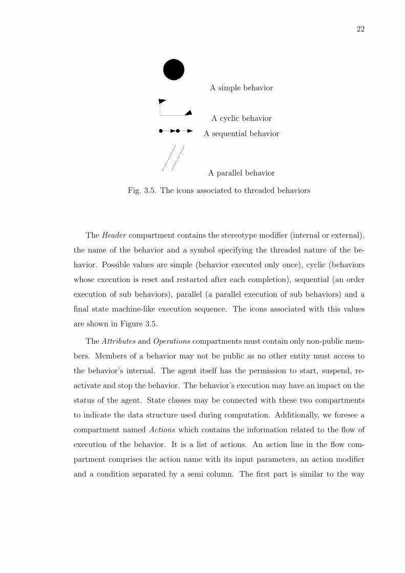
The Header compartment contains the stereotype modifier (internal or external),
the name of the behavior and a symbol specifying the threaded nature of the be-
havior. Possible values are simple (behavior executed only once), cyclic (behaviors
whose execution is reset and restarted after each completion), sequential (an order
execution of sub behaviors), parallel (a parallel execution of sub behaviors) and a
final state machine-like execution sequence. The icons associated with this values
are shown in Figure 3.5.
The Attributes and Operations compartments must contain only non-public mem-
bers. Members of a behavior may not be public as no other entity must access to
the behavior’s internal. The agent itself has the permission to start, suspend, re-
activate and stop the behavior. The behavior’s execution may have an impact on the
status of the agent. State classes may be connected with these two compartments
to indicate the data structure used during computation. Additionally, we foresee a
compartment named Actions which contains the information related to the flow of
execution of the behavior. It is a list of actions. An action line in the flow com-
partment comprises the action name with its input parameters, an action modifier
and a condition separated by a semi column. The first part is similar to the way

23
we define operations in the operation compartment. Action modifiers are reactive,
proactive and internal. Reactive means the execution of the action is fired after an
external stimulus (the content of the condition part). Proactive means the action is
internally fired after a condition is met.
Complex actions rely on the execution of methods or sub behaviors or both.
These elements are connected to the action by means of a solid line and the action
is wrapped by a circle (see Figure 3.4).
A behavior has thus an Operations compartment where the internal operations
are captured and an Actions compartment where that action corresponding to re-
active and proactive actions are detailed. The difference between the two lies in
that actions represent higher-level actions that can map in more operations or even
in a set of sub behaviors, while operations are punctual and play the role of usual
methods. Actions have an associated modifier and condition, operations have not.
Actions can be connected to behaviors, operations to state which represent the data
structure they use. Actions represent what behaviors offer to agents, operations
how actions can be carried out. A behavior can posses the action “Find the best
deal” related to a commercial item. The outcome of this action depends on how the
operation “Quote a deal” operates, i.e it is price-oriented or it considers also other
features (warranty, quality, experience and so on).
3.4 Behavioral matching
An external behavior specifies all data necessary to find out matching behaviors,
that is behaviors of other agents that could possibly fulfill the expected functions
of the external behavior. Behaviors are publicly advertised detailing the actions
they provide and how they can be accessed (protocols). This corresponds exactly
to the public part of the behavior in our AUML class diagram. We essentially need
the Actions compartment and the Protocol compartment. The former contains the
actions that the behavior is expected to perform. Actions once again have their

24
parameters, pre- and post-conditions and conditions that have to be verified during
execution of the action itself. The Protocol compartment specifies the protocols the
behavior supports to call for other agents’ behaviors. While actions are placeholders
for matching other behaviors, protocols are needed to ensure the behavior can cor-
rectly interact with matching behaviors. Matching actions and protocols ultimately
provides a mechanism for binding agents together, thus creating coordination. The
process can be so simple as querying a behavior registry or as complex as negotiating
service availability and conditions.
If the behavior is a learning one, then we suggest to approach the design as done
in [BTS+04]. Note that as behaviors are learned, we may want to update their design,
modeling the created behaviors. This is possible for instance for neural networks,
for which we could write the weight configuration.
3.5 Interactional view
One important aspect of multi-agent systems is how agents come to interact.
With class diagrams we have seen how the system can be statically designed. The
mechanism of behavioral matching clearly shows that communication between agents
is needed to enable cooperation or collaboration. It is the purpose of the interac-
tional view to clarify how this interaction may happen and according to which rules.
The interactional view encompasses sequence diagrams, interaction overview dia-
grams, communication diagrams and timing diagrams. We focus here on sequence
diagrams as they propose the richest insight of the interaction. Other diagrams
either express similar information in different ways (communication diagrams) or
simpler information (interaction overview diagram and timing diagram). Through
sequence diagrams we ultimately design how coordination can be produced among
agents thanks to communication patterns.

25
3.5.1 Background
The modeling of communication protocols is not a new topic in computer science
[Hol91,SW00].
Techniques mutuated from other computer science areas and adapted to multi-
agent system interaction design include finite state machines, Petri networks [Arg79,
Pet81], the Z notation [Spi89], the Specification and Description Language (SDL)
and temporal logic [FW94].
Final state machines represent an intuitive tool for depicting the flow of action
and communication. They are useful for a first approach to conversation modeling
and sufficient for modeling sequential interactions. As conversations grow in size
and complexity, concurrent patterns emerge, final state machines suffer some limi-
tations in capturing the dynamics of protocols. Petri networks are more suited to
model concurrent processes. Petri networks or place transition networks are directed,
connected, bipartite graphs in which each node is either a place or a transition. To-
kens occupy places. When there is at least one token in every place connected to
a transition, we say that the transition is enabled. Any enabled transition may
fire, removing one token from every input place, and depositing one token in each
output place. Applying high-level Petri networks to the specification of multi-agent
systems can be found in a number of works [Hol95,HK98,MW97,PC96]. In partic-
ular [CCF+99,CCF+00] proposes to use a variation of Petri networks called colored
petri networks (see [Jen92,Jen94,Jen97]) to model agent interaction.
The Z notation is a formal specification notation based on set theory and first
order predicate logic and generically intends to describe computer systems and their
behaviors. In [dL96], the authors provide an example on how to use this notation to
formalize the contract net protocol [Smi80] in terms of nodes, agents, tasks, goals and
actions. Such an approach leads to very precise conceptions of a system, resulting
in non-modular and sometimes difficult-to-read design.

26
SDL is an object-oriented formal language for the specification of complex, real-
time applications. It is a graphical language that is both formal and object-oriented.
The language is able to describe the structure, behavior, and data of real-time and
distributed communicating systems with mathematical rigor. It has been used in the
Mas-Common Kads methodology [IGCGV98] for the coordination model of agents.
The most significant approach born in the area of multi-agent system is AgentTalk
[KIO95]. AgentTalk is a programming language capable of implementing protocols
and agents that behave according to them. AgentTalk does not support a specific
agent model. The main features of AgentTalk are:
• explicit state representation: an extended finite state machine is used as a basis
to describe coordination protocols;
• incremental protocol definition: as in an object-oriented language, a protocol
can be incrementally defined by inheriting a definition of an existing script (a
script in AgentTalk represents the state transition of an agent in a protocol);
• protocol customization: when calling a protocol execution, agents can provide
their specific delegate functions to be executed on state transitions;
• conflict resolution between coordination processes: as protocols may be simul-
taneously executed, we need a mechanism to get these protocols communicate
in order to solve conflicts.
Our aim is to find a notation with which designers can capture the essential traits
of an interaction among agents, both at a high-level of abstraction (what we usually
call conceptual level) and at a detailed level (what we usually call implementation
level). The notation should be neutral with respect to any methodology designers
may adopt to design the system. The presented approaches fail to address these
requirements for various reasons. The AgentTalk language misses a proper notation.
Petri nets and the Z notation require a detailed view of the system, that may produce
difficult-to-read projects or over verbose views in the early design stages. They fail
in incrementally representing the system. SDL is bounded to a methodology.

27
3.5.2 Agent UML
AUML does not compete with any of above efforts. It rather aims at extending
and applying a widely accepted modeling and representational formalism (UML) in
a way that harnesses their insights and makes it useful in communicating across a
wide range of research groups and development methodologies. AUML proposes an
intuitive way to design system, hopefully with enough expressive power to catch the
peculiarities of agent interaction. Most probably, once we have designed the system,
other approaches may be used to give insights on particular parts. For instance,
Petri networks seem to suit a precise and fine-grained view of interaction processes.
AUML sequence diagrams are informed by these requirements. The preliminary
move towards sequence diagrams 2 for multi-agent systems was done in [BMO00].
They represent an extension to UML 1.5 state and sequence diagrams. Extensions
included:
• agent roles: an agent role abstracts the properties, interfaces, service descrip-
tions and behaviors shared by a set of agents;
• multi threaded lifelines: an agent lifeline in sequence diagrams defines the
time period during which an agent exists. It is possible to specify parallel or
concurrent message flows by means of AND, OR and XOR connectors;
• extended message semantics: messages can be synchronous or asynchronous
and have cardinalities;
• nested and interleaved protocols: protocols are designed in a modularized way
so as to allow their composation and their interleaving.
Many of these concepts are encountered in later work, refined and expressed
by means of a notation which takes into consideration the evolution of UML 3.
2What is now called sequence diagrams was named by Bauer as protocol diagrams to highlight thedistinction with UML. The same name has been used by succesive work by Huget. In order toavoid overlapping concepts, we call them sequence diagrams as the authors do in the FIPA draftproposal to comply with UML 2.0.3In the meanwhile, UML has evolved from version 1.5 to version 2.0

28
The subsequent step towards AUML sequence diagram specification has been done
by Huget in [Hug02b]. Huget added new features such as message broadcasting,
messages triggered by conditions, interaction synchronization, a form of exception
handling, time management with deadlines and delays between messages and atomic
transactions.
In the following we present these concepts conforming to the latest FIPA specifi-
cation [Mod03a]. We remind that specifications about AUML have not a definitive
form and are subject to changes. We finally propose possible extensions to the model.
3.6 Sequence diagrams
The notions encompassed in AUML protocol diagrams are the followings:
• frame: frames encapsulate all the elements used in the interaction protocol as
a unit. It is depicted as a solid-line rectangle with a sd header on the upper-
left corner. sd stays for sequence diagram and is followed by the name of the
protocol;
• protocol templates: they are determinate by the stereotype � template �
(see Figure 3.6a). A template defines a pattern for a protocol. Information in
a protocol pattern can be prefixed by the stereotype � unbound � making it
a parameter to be specified when creating instances of the template protocol.
A frame representing an instance of the protocol template will have attached
the list of parameters that correspond to that particular instantiation (see
Figure 3.6b). Mandatory parameters for each protocol instance corresponds to
the keywords ontology, ACL (agent communication language) and CL (content
language);
• agents and their roles: agents have an identity, i.e. they are an instance of
some entity and play one or more roles. We have a box for each instance and
for each role this instance plays in the protocol;

29
(a) (b)
Fig. 3.6. The (a) template protocol and (b) its instantiation with parameters.

30
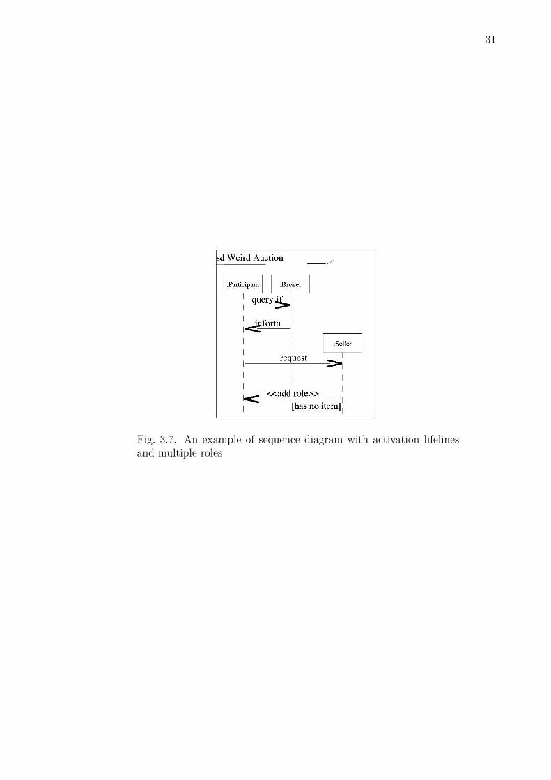
• agent lifelines: in Agent UML lifelines can be associated not only to particular
instances of agents (like in UML 2.0 happens for objects) but can also be
associated to roles and groups, or to agent instances playing specific roles in
certain groups. A role is a class that defines a normative behavioral repertoire
of an agent. A group is a set of agents that are related via their roles, where
these relationships must form a connected graph within this group [Ode02]. A
lifeline represents the time frame an agent instance playing a role in a group
is active during interaction. It is depicted as a vertical dashed line headed by
a label box, containing an agent identifier and/or a role and possibly a group
and the cardinality of the agents playing that role (see Figure 3.7). Time flows
going from top to bottom. Multiple classification, i.e. an agent playing more
than one role within the same interaction, is obtained by using labels with equal
values of the agent instance. Dynamic classification, i.e. agents changing roles
during interaction, is rendered as a directed line from the current role to the
new role. The directed line is adorned with the stereotype � change role �.
If new roles are added during interaction, then we use a directed line adorned
with the stereotype � add role � (see Figure 3.7);
• messages: information about messages is spread in the diagram. The sender
is the agent or role the directed line starts from. The receiver is the agent or
role pointed by the directed line. The ontology, the language and the content
language are parameters attached to the diagram. The communicative act and
its content are adorned on the directed line. The notation for a message is
a line from the lifeline of the sender directed to the lifeline of the receiver.
Asynchronous messages have an open arrowhead, while synchronous messages
have a filled arrowhead. In the case the lifeline of the sender and receiver are
the same, we may precise that the sender agent will not receive the message
by barring the beginning of the directed line;
31
Fig. 3.7. An example of sequence diagram with activation lifelinesand multiple roles
32
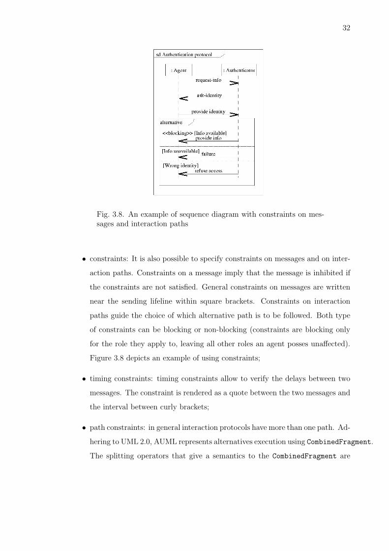
Fig. 3.8. An example of sequence diagram with constraints on mes-sages and interaction paths
• constraints: It is also possible to specify constraints on messages and on inter-
action paths. Constraints on a message imply that the message is inhibited if
the constraints are not satisfied. General constraints on messages are written
near the sending lifeline within square brackets. Constraints on interaction
paths guide the choice of which alternative path is to be followed. Both type
of constraints can be blocking or non-blocking (constraints are blocking only
for the role they apply to, leaving all other roles an agent posses unaffected).
Figure 3.8 depicts an example of using constraints;
• timing constraints: timing constraints allow to verify the delays between two
messages. The constraint is rendered as a quote between the two messages and
the interval between curly brackets;
• path constraints: in general interaction protocols have more than one path. Ad-
hering to UML 2.0, AUML represents alternatives execution using CombinedFragment.
The splitting operators that give a semantics to the CombinedFragment are

33
Alternative, Option, Break, Parallel, Weak and Strict Sequencing, Negative,
CriticalRegion, Ignore, Consider, Assertion and Loop. In order to iden-
tify splitting paths we use a solid-outline rectangle with the operator written
in a top-left “snipped corner” pentagon. Each optional path is separated by a
dashed line. The merging operator is called Continuation. Continuation is
rendered as a rounded rectangle with a name. A Continuation can be outgo-
ing (a filled triangle is depicted after the name) or incoming (a filled triangle
is depicted before the name);
• protocol combination: we may have interleaved protocols. This happens when
the execution of a protocol foresees at a certain stage the execution of another
protocol. The execution of the principal protocol continues after the interleaved
protocol execution finishes. Graphically, this is rendered by a solid-outlined
rectangle. Designers must pay attention to coherently match role when passing
from one protocol to the interleaved one;
• protocol interaction: two protocols may come to interact in that the first sends
a message to the second passing information and the second, after finishing
some execution, sends information back to the calling protocol. As interaction
happens through messages we can have blocking or non-blocking relationships.
We represent protocol interactions using the usual message notation.
3.7 Experiencing AUML sequence diagrams
In this section we consider some uses of AUML sequence diagrams. This has
the purpose to show the expressiveness of AUML and to propose extensions. The
following observations have been inspired by our experience in using AUML on fielded
systems (see chapter 5 and 6).

34
Fig. 3.9. A broadcast message
3.7.1 Sending messages to more than one agent
In protocols it often happens that one agent has to send a message to a group of
agents. The group can be the totality of the agents present in the environment and
in this case we have a broadcast or to a subset of them and we call this multicast.
Broadcast messages are sent to an undetermined set of agents. Broadcast mes-
sages do not address any particular group, role or agent instance. They are repre-
sented with a message line closed by an arc (Figure 3.9). The line must not meet
any lifeline. As normal messages, broadcast messages can be synchronous or asyn-
chronous. We may precise whether the sender itself receives the message or not. In
the latter case, we bar the beginning of the directed line.
Multicast messages can be rendered in AUML at three different levels, corre-
sponding to groups, roles and agent instances. At group and role level, the simplest
form of multicast is when a message is sent to all agents belonging to that group
or playing that role (see Figure 3.10(a)). For roles, the number of agent addressed
depends on the role cardinality. A second form of multicast happens when we want
to identify, among all agents belonging to a group or playing a role, a distinct subset.
This might be the case of a single agent or group of agents winning an auction: only
winners have to be notified of their success. We call this messages selective multicast

35
messages. Our suggestion is to adorn the message with a number expressing how
many agents should be addressed (possibly a range) and a condition which filters
out the agents which hold a distinctive property (see Figure 3.10 (b)). Only the
number or range is optional. At the level of agent instances, a multicast message
must be represented with a line which forks to direct to the different agents lifelines
(see Figure 3.10 (c)). No number or ranges nor condition specific to multicast must
adorn the message line.
(a) (b) (c)
Fig. 3.10. Multicast messages: (a) simple, (b) selective and (c) to agent instances.
As more agents can be involved in an interaction, there might be the need for
creating a synchronization at some stage. A synchronization is a point where all
agents are expected to get and until all required agents are not arrived at that point
of the protocol execution, the protocol cannot further execute.
Synchronization points can be of two types. Simple synchronization points are
related to synchronization on messages. Suppose an agent asks to all agents of a given
role if they are up and running and the asking agent will undertake further actions
only when all answers have been received. In this case, the message arrowhead is
crossed out by a vertical line. Synchronization can also be applied to merging paths.
Execution must not go on until all paths have reached the merging point. To model
synchronizing merging points we bar the arrow of an incoming Continuation box
(see Figure 3.11).

36
(a) (b)
Fig. 3.11. Synchronization for (a) messages and (b) merging paths.

37
3.7.2 Trigger management
Triggers are actions to be undertaken under particular conditions. We identify
two types of triggers. Those that fire after an exception and those that fire when
specific conditions are met.
The notions of exception and exception handling are important in programming
any computer system. An exception fires when a behavior does not complete suc-
cessfully. Handling exceptions means getting catching it and adopting responsive
actions. In AUML exceptions can be inserted using the Break operator, one of the
splitting path operators we have listed above. The Break operator starts a break-
ing scenario that stops the current execution of the sequence diagram, executes the
scenario and does not resume the main sequence flow.
We suggest to use a similar mechanism to model triggering actions. Triggering
actions take place when particular conditions are met. Triggering actions are like
exceptions, but their execution does not break the interaction. After a triggered
action we always resume the main sequence flow. We use once again the break
operator with a resume keyword in the label as in Figure 3.12.
3.7.3 Atomic transactions
Atomic transaction is a concept developed for database systems. An atomic
transaction collects a set of actions to be executed after some sequence. The ex-
ecution is to be deemed successful only if all actions terminate successfully. If at
least one action does not, all the results produced by the execution of the success-
ful actions must be rolled back. This is to say that we have either the combined
result of all actions or none. In AUML we could think to model this aspect using
CriticalRegion, a splitting operator. A CriticalRegion tells us that a sequence
of actions has to be executed atomically with no interleaved message sequences. We
claim atomic transactions are different from critical regions. Atomic transactions
are not only atomic but imply that in case of failure to complete that sequence, the

38
Fig. 3.12. Representing triggered actions with the resuming Break operator

39
Fig. 3.13. An atomic transaction is represented by the tt Transac-tionRegion operator
state is brought back to the value it had before the atomic transaction started. We
add therefore a new splitting operator called TransactionRegion (Figure 3.13).
3.8 Comparison with previous AUML proposals
In this section we will point out the main differences between our extensions and
what has been proposed in previous work on AUML.
As for AUML class diagrams, we referred the work by Bauer [Bau02] and Huget
[Hug02a]. As Bauer we distinguish between methods, which are internal, and actions,
which are the visible behavior of an agent. With respect to both approaches, we
enrich the diagram by distinguishing classes into behaviors (internal and external)
and services. This gives us the possibility to describe in a modular way the behaviors
associated with an agent. We can connect actions to the operations that they imply
or to those sub behaviors that realize parts of its functioning. This also helps identify
coordination link among agents.
As Huget we represent the state of an agent with objects, because objects are
handier to manage than simple variables stating conditions like tire(2000km, in-

40
flated). The state of an agent changes when an agent operation or one of its behavior
acts on it invoking the available methods.
Huget includes in class diagrams a Capability compartment. Capabilities describe
what agent are able to do in a free-format text. Capabilities are derived as services
to agents. These services are rendered as lollipops linked to the agent. We use a
different approach. We have behaviors, which can be internal or external. A generic
behavior may be associated with an action. An action has a condition which tells
why it fires. External behaviors have to be matched against the services available in
the environment. In this way, we try to capture as much as possible the structure of
the system, reducing the free-format text and precising the relationships among the
diverse elements along with their nature.
As for AUML sequence diagram, we have been mainly inspired by the current
working draft on interaction protocols by FIPA [Mod03a]. In proposing our exten-
sions fundamental has been a work by Huget [Hug02b]. With respect to the latter,
we have proposed extensions which suit the current AUML interaction protocol draft
which refers to UML 2.0. Differences mainly concern the use of the notation and how
we discern concepts like multicast messages, triggered actions, exception handling,
atomic transactions and critical regions.
3.9 Conclusions
In this chapter we reviewed the definition of software agents. First, we have dis-
cussed their qualitative features and showed how perspectives belonging to different
disciplines concur in defining the character of agent technology. Despite different
views in the literature, commonalities can be found. Autonomy plays a central role
with its many facets. Intelligence is another key feature to which we assign different
degrees (reactivity, pro activeness and learning). Secondly, we showed how we can
practically design systems holding such features. Our analysis has been inspired by
the recent moves towards extending UML for multi-agent systems. Reviewing the

41
current proposal, we have proposed some extensions aiming at facilitating the design
of a system which contains software agents. Our observations are not meant to be
stable and reliable, but are intended to put forward themes that we consider essential
to capture the nature of multi-agent system from a design perspectives. Insights on
experiencing AUML are given in [BGGV03a,BGGV03b].

42
4. ARCHITECTING AGENT SYSTEMS
Discussing the design of information systems with software agents we pointed out
how the environment plays an active role in multi-agent systems. Basically, the
properties of the environment determine the “nature” surrounding the agent, what
actions can be done and which resources are available. The environment may also
influence how agents are built, providing the means by which agents can execute,
communicate, move and use resources. This chapter is dedicated to present how the
environment of software agents is modelled and implemented in multi-agent system
toolkits.
With respect to physical agents which may live in the same environment humans
experience, software agents seem to have a more limited living space. They execute
in computer systems, usually connected through computer networks. This physically
bounded space is virtually huge. Physical distances are hidden by a uniform logical
addressing space. Basically we find three reasons for which this environment is
difficult to model. First, dealing with distribution in computer systems requires to
build software layers capable of supporting the system activities we find on local
systems such as identification, messaging, data transfer and resource localization.
This has to be done in a transparent way so as to lessen applications from the
burden of managing distribution. Secondly, as for physical agents, software agents
should include a representation of the external world in terms of software (agents,
objects and services) and hardware (disks, printing facilities, networks, and in general
physical devices) resources. Thirdly, virtual environments may be enriched as to
resemble to physical environments (sometimes they even amplify physical nature).
This is the case of simulation systems in which virtual environments implement

43
physical laws such as the effects of magnetic fields or social dynamics. An example
of an agent-based simulation environment is KidSim [SCS94].
Tackling these issues means creating a software layer that has richer functionali-
ties than those available from an operating system. Most commonly, the solution is
building a software layer which abstracts the execution environment on the top of the
operating system. We call this layer an infrastructure. The study of multi-agent sys-
tem infrastructures is a relatively young field. While fairly sophisticated theories and
technologies have been developed in fields like coordination, interaction, languages
and dynamic organizations for agents, we have little experience about the practi-
cal deployment of multi-agent systems. This may also be viewed as a reason why
agent-based systems have not yet become a widespread technology in commercial
applications. Experiences in other areas have showned that until a critical mass of
fielded systems is in place, pulling towards stable, reliable, accessible infrastructures
offering compelling services, the potential of agent technology will not be converted
into kinetics. In this chapter, we will discuss which are the mandatory features of
a virtual environment for software agents on top of which we can build more so-
phisticated dynamics. The ultimate vision is that of Russel and Norvig [RN03] “the
Internet is an environment whose complexity rivals that of the physical world and
whose inhabitants include many software agents”.
4.1 An abstract infrastructure model
A technical infrastructure is meant to provide solutions to basic, essential, com-
monly problems experienced when tackling a particular category of systems. Ex-
ploiting an infrastructure means taking advantage of its features in order to focus
on application-specific issues, avoiding costly and repetitive activities. The quality
of an infrastructure resides in how well it satisfies global needs that are useful for
building specific applications. Using general purpose infrastructure for solving a
range of specific problems allows shared knoweldge and use of common criteria in

44
the community. Following Star and Ruhleder, in general infrastructures hold the
following properties [SR96]:
• they are built on top of other structures. Technically, the most common ex-
ample of infrastructrue is middleware [Mye02,Bri01];
• they are transparent to users as they offer services that can be used with a
high-level interface and manifest from a design standpoint;
• they are based on standard specifications and learned community practices.
The infrastructure of a multi-agent system includes the set of services and knowl-
edge to support the agent’s social activities such as coordination, communication and
mobility. Figure 4.11 depicts one of the most popular models which has been pre-
sented in [SPVG01] for the RETSINA toolkit. The layered placement suggests that
each level exploits the services of the underlying levels.
A MAS infrastructure is built upon an operating environment. An operating en-
viroment is composed by computers, operating systems, networks and how they are
interconnected. While relying on the services provided by this layer, a MAS infras-
tructure should make agents unaware of the underlying operating environment. In
this way, software agents may work across heterogeneous settings. The lower level of
a MAS infrastructure is represented by the communication infrastructure. The com-
munication infrastructure is responsible for message transfer. Message transfer can
happen both among agents and between an agent and the infrastructure components
(these latter may or may not be agents themselves). Communicating with infras-
tructure components assumes the components can be easily addressed by means of
a discovery service. No matter what the modality of the communication channel is
(wired, wireless, infrared ,...), agents should be able to exchange messages. The com-
munication service should also be independent from the actual transport layer and
1The original figure has two columns, the undepicted one representing the individual agent infras-tructure. We are not concerned here with the individual agent architecture because it is implied bythe infrastructure, i.e. if the infrastructure offers services, agents executing in such infrastructureare given the capabilites to effectively exploit them.

45
Fig. 4.1. The abstract agent infrastructure derived form the RETSINA system

46
from the particular Agent Communication Language (ACL) used in messages [SS00].
The specification of an ACL rules both the syntactic form of the language and the
semantics associated with its primitives, called speech acts. The interpretation of
messages by an agent is done according to some specified ontology. Further to mes-
sages, we may specify which conversational policies [GHB00] are enforced and which
protocols [SCB+98] can be used to carry out conversations.
A MAS infrastructure supplies other high-level services. The multi-agent man-
agement services comprise the set of services needed to control the system (logging,
management tools, installation and launching services). Performance measurement
may also be in place for monitoring the performance of software agents and evaluate
their features (as for instance their reliability or reputation [ZMM99]). As multi-
agent systems are open systems, where agents dynamically appear and disappear,
programmed by different people, we need to secure the system against misuse of
its resources and misbehaviours towards agents. The security layer responds to this
requirement.
A MAS infrastructure provides also a location abstraction, supporting software
agents that move in the environment. This is achieved by activating what is named
an Agent Name Server (ANS) which registers the name of each agent together with
its current positions. Messages sent to the agent are routed according to the informa-
tion stored in this table. The ANS keeps the table up-to-date in a real-time fashion.
Supporting mobile agents brings into play the issue on how agents can meet and find
each other capabilities while changing location over time. The Capability to Agent
Mapping layer makes provision of the service through middle agents [DSW97]. Mid-
dle agents hold registries which store entries related to agents and the descriptions
they advertise about their features. This service may be rendered in a number of
ways as investigated in [WS00]. The upper layer of the infrastructure is dedicated
to make the MAS interoperable with others MASs, which will be in general designed
and implemented independently and responding to different architectures. Making
diverse MASs interoperate (for instance knowing the agents that enter the system
47
and make them reachable by messages) is a very important task and a very difficult
one. In order to promote interoperability and discussion on MAS infrastructures the
Foundation for Intelligent Physical Agents (FIPA) has been constituted with the
aim of pursuig agent standards. In the next section, we present the FIPA standard
model for MASs.
4.2 FIPA: a standard model for MAS infrastructures
The model presented above was developed by abstracting the architecture of
RETSINA, one of the first complete agent environment implemented and has been
useful to introduce the basic layers a multi-agent system should comprise. We will not
comment on the quality or coherence of the model. What is important is that what
observed was a premise for further efforts, and in particular to the initiative of FIPA
aimed at creating a standard specification for multi-agent system infrastructures.
The FIPA agent management reference model [fIPA04] and the abstract archi-
tecture [fIPA02a] define the framework within which FIPA agents exist and operate.
They detail the logical reference model for the creation, registration, location, com-
munication, migration and retirement of agents. According to the FIPA specifica-
tions, the infrastructure is composed by (see Figure 4.2):
• agents as computational processes with an identity (unique identifier called
Agent Identifier), an owner (a human or an organization), a service description
which describes their capabilites. Agents communicate using an ACL. A single
agent may be contacted at a number of logical addresses;
• a directory facilitator (DF) provides yellow pages services to other agents that
can be used by agents to register, unregister their services and query in order
to know other agents. While a DF is optional in the system 2, it is possible to
have more federated DFs exchanging data about agents. If a DF has federated
2If present, the DF has a reserved AID of the form (agent-identifier :name df@platform :addresses(sequence platform transport address))

48
Fig. 4.2. The FIPA reference model
companions, then executing a search means first looking at its own table and
then extending the search to other DFs;
• an agent management system (AMS) is responsible for controlling the access
and the use of the agent system. It offers a white pages service. Each agent
must register with the AMS. The AMS stores all the information about agents
required to excert its control over the platform. An AMS is mandatory and
unique in the platform 3;
• a message transport service (MTS) is the default communication method be-
tween agents on different platforms.
All the actions related to management activites within the platform (such as
registrations, changing states, moving form one place to another) have a correspond-
3The AMS on an AP has a reserved AID of: (agent-identifier :name ams@platform :addresses(sequence platform transport address))

49
ing standard message type with standardized parameters. This ultimately defines a
management ontology which is shared and known to all agents in the platform.
It must be noted that no mandatory requirements concerning how a platform is
actually designed are imposed by FIPA. To be compliant with the FIPA specifications
it is only requested that all defined services are in place.
4.2.1 The directory facilitator
The DF basically provides yellow pages services. As a service provider it is sup-
posed to be reliable and securely open. Reliable as it must keep a view of the system
up-to-date in a real-time fashion. If an agent has advertised a service description, the
directory facilitator must, from that time on, answer to queries with the updated
data. Securely open as it must be available to all regularly authorised agents in
the platform. All the management functions can be requested by agents using the
fipa-request interactional protocol [fIPA02b]. The DF may restrict access to in-
formation in its directory and verify all access permissions for agents which attempt
to inform it of agent state changes.
The DF is a passive component: every agent can register its own services, but
it is not guaranteed that the agent actually provides such services or is willing to
do so upon request. No restrictions are placed on the data that are supplied for
registration. If an agent deregisters its services the DF is no longer committed to
broker information relating to that agent.
Searches submitted to DFs are carried out locally by the receiving DF. If re-
quested and a federation of DFs is active, the DF will ask companion DFs to perform
the same search. In order to create federations, directory facilitators must register
their service with each other.
Additionally to single queries, a DF may support also persisted queries. This is
realised through a subscription mechanism4. Agents submit the query to be persisted
4The mechanism is implemented by means of the fipa-subscribe interaction protocol [FIP02]

50
and the DF will inform them when changes to the result of the subscribed query
happen.
4.2.2 The agent management system
An agent platform is mandatorily managed by one AMS. The AMS holds a
description of the agent platform itself and of all agents in the system. While the
DF holds data about agents’ services, the AMS description of an agent contains the
logical addresses of the agent. Each agent to get to execute must register with the
AMS of the platform it was born in. Upon registration an agent receives a unique
agent identifier. Deregistration is possible only when the agent deceides or is forced
to terminate.
As an agent platform is a logical abstraction that may span over multiple physical
machines, the AMS represents the authority across all machines.
4.2.3 The message transport service
The MTS is the most complex service within an agent platform. The MTS is
charged of delivering messages between agents within a platform. If other platforms
are attached, it must also make possible messaging to agents that are resident on
other platforms. Each agent must have access to at least one MTS in order to be
able to communicate. An MTS is intended only for messages sent to agents. On
a particular platform, an MTS is instatiated by a so-called Agent Communication
Channel (ACC).
The reference model for an agent message transport comprises three levels as
shown in Figure 4.3:
The object to be delivered is a message. A message comprises two parts: a
message envelop holding transport information and a message payload with the ACL
message the agent wishes to communicate. A receiving agent is mainly interested in
interpreting the ACL message for which FIPA defines the semantics. The information

51
Fig. 4.3. The reference model for the agent message transport

52
in the envelop is for transportation support only. FIPA does not specify whether
and how this information may be processed by receiving agents. A message envelop
contains a list of parameters in the form of name/value pairs. A message transport
protocol may use different internal representaion of a message envelop but must
express them in a standardized way. Mandatory parameters concern the receiver
of the message (parameter to), the sender (parameter from), the time the message
is sent (parameter date) and the representation of the ACL message (parameter
acl-repesentation). Each ACC handling a message may add new information to
the message envelope, but it may never overwrite existing information. An ACC must
transfer the messages it receives according to the transport instructions contained
in the message envelope. An ACC is only required to read the message envelope; it
is not required to parse the message payload. In performing message transfer tasks,
the ACC may be required to obtain information from the AMS or DF.
Message routing is performed as follows. If the ACC receives a message with
the intended-receiver slot, then it forwards the message to the agent specified
in that slot. If multiple receivers are specified then the most recent one is taken.
If the intended-receiver slot is empty, then the ACC fills it in with the names
comparing in the to slot. In delivering a message to a receiver agent, an ACC looks
up the addresses specified for that AID. If the agent posses more addresses, the
the ACC first try to reach the agent using the first in the list. If the operation is
unsuccesful it iterates through the list of addresses. If still unsuccesfull, the ACC
may try to resolve the AID by contacting alternative resolvers (usually those listed
in the resolvers parameter of the agent identifier, as specified in [fIPA04]). If still
unsuccesful, a failure message is sent to the sender.
In the setting of more agent platforms, an agent desiring to communicate with an
agent on another platform has two possibilities. The first is to send the message to
its local ACC. The ACC then takes care of sending the message to the correct remote
ACC using a suitable MTP. The remote ACC will eventually deliver the message.
The second is to send the message directly to the ACC on the remote agent platform

53
on which the receiver agent resides. This remote ACC then delivers the message to
B.
4.3 JADE
Since the early stages of FIPA activity, researchers have not only contributed to
delineating the standard but also to test the feasibility of a FIPA-compliant toolkit.
The first FIPA standards were published in 1997. The first FIPA-compliant product
was released in 1999 by Nortel Networks and was called FIPA-OS. It was soon
followed by other examples both as licensed products and open source projects.
Commercial products are the Agent Development Kit by Tryllian BV, Cybele by
Intelligent Automation Incorporated and JACK by AOS. Open source projects are
FIPA-OS by Emorphia (spin-off company by people of the former agent group in
Nortel Networks), the Java Agent DEvelopment JADE by TILab, the April Agent
Platform (AAP) by Fujitsu and ZEUS by BT.
Open source projects have demonstrated to be very appealing for the research
community due to free usage and source code availabilty. This gives the chance to
researchers to build toolkits ahead of commercial products as the research advance.
As a matter of fact, many open source projects were born thanks to researchers’
effort.
Another issue concerns programming languages and more specifically Java TM.
With its multi-platform and network programming support, JavaTMrepresents the
ideal choice in developing multi-agent systems and environments. With respect to
these points, the most succesful projects have been FIPA-OS and JADE. JADE in
particular has been having a big momentum and current releases merge the state-
of-the-art techniques in agent environments.

54
Fig. 4.4. A JADE platform
4.3.1 The JADE agent platform
JADE is a toolkit for implementing and deploying multi-agent systems 5.
JADE complies with the FIPA specification and as such provides an agent man-
agement system, a directory facilitator, the FIPA Management Ontology to contact
their services, and a message transport system.
A JADE platform is a logical space that can be distributed over diverse physical
hosts (Figure 4.4). Each host participating to the platform has its own Java Virtual
Machine running. Each JVM is an agent container, i.e. a runtime environment
that allows agents to concurrently execute. In order to boot the platform, a Main-
Container has to be created. The Main-Container hosts the AMS and the DF. It
also contains the RMI registry that JADE uses to allow containers and agents to
reside on multiple hosts. Other virtual places can be added to the platform by
creating containers. Containers may or may not reside on the same host where the
Main-Container runs. No matter where containers are located, the agent platform is
seen as a uniform logical space, where all containers can be reached simply knowing
their name.
5At the time of writing JADE 3.2 is the latest release

55
JADE provides compliant implementation also for the agent communication lan-
guage with its speech-acts, content language support, and the FIPA interaction
protocols.
4.3.2 The JADE agent model
The JADE agent model defines agents as running thread. The JADE Agent class
implements indeed the Runnable Java interface, meaning that agent instances are
executed by a thread. Developers can therefoer program their own agent inherit-
ing from the JADE Agent class. When instatiated, an agent is assigned a Java
thread which takes hold of its execution. The template Agent class defines features
to accomplish basic interactions with the JADE agent platform such as start-up
registration, service registration, service querying, roaming and sending messages.
As an entity of a MAS, each agent is identified by an Agent Identifier (AID)
(see FIPA Abstract Architecture Specification [fIPA02a]). An AID labels an agent
so that it may be distinguished unambiguously within the platform. The Jade AID
is an abstract data type which includes a number of fields, the most important
of which are name and addresses. The name field contains the globally unique
identifier (GUID) assigned to the agent. A GUID is constructed by concatenating
the nickname assigned by the launching user to the name of the platform the agent
was born in, separated by the ’@’ character. GUID are used to identify receivers of
sent ACL messages. The addresses field, instead, contains a number of transport
addresses at which an agent can be contacted. The syntax of these addresses is just
a sequence of Uniform Resource Identifiers (URIs). When using the default IIOP
MTP, the URI for all the local addresses is the Interoperable Object Reference of the
local agent platform.
As a running thread, instead, an agent has a life-cycle, i.e. can be in different
states. Following the FIPA Platform Lifecycle Specification [fIPA] an agent can be
in one of the following states at a given time (see Figure 4.5):

56
• initiated: the agent is instatiated as object but does not hold the agent features
such as a valid AID and a registration entry by the AMS. In this state the agent
cannot communicate with other agents;
• active: the agent was instatiated and now has all the required agent features.
It can communicate with other agents and execte behaviours;
• suspended: the internal thread of the agent is stopped and all behaviours are
blocked;
• waiting: the agent thread is sleeping on a Java monitor and can be woke up
by some event (typically an incoming message);
• deleted: the agent stops living, its thread termintes and the agent is no longer
registered by the AMS;
• transit: this state allows to know when an agent is moving. While the agent
is moving cannot receive messages. The messages sent to the agent must be
buffered by the platform services and delivered when the agent leaves this state
to the new location;
• copy: this state is internally used by JADE for agent being cloned;
• gone: this state is internally used by JADE when a mobile agent has migrated
to a new location and has a stable state.
The Agent class provides methods to command state transitions.
When in the active state, agents can execute its operations. More precisely,
in JADE agents’ actions are called behaviours. Behaviours can be simple as the
execution of one single action or a set of actions to be executed only once, or complex
such as the execution of actions in strict sequence or in a parallel fashion. Agents
may execute more than one behaviour at a time. A JADE agent has thus a multitask
computational model which allows the execution of whatever combination of simple
and complex behaviours. This is achieved by implementing an internal scheduler

57
Fig. 4.5. The possible states for an agent

58
which interleaves the execution of the agents’ behaviours. The result is that tasks
are executed concurrently, assigning each a slice of time in a non-preemptive way.
The scheduler is hidden to the programmer and automatically schedule agents’ tasks.
Control by an agent over the behaviour execution can be done at two levels. A finer
level of control is reached by using the block() method on a behaviour. This will
block only the activities related to that behaviour. A coarse grain control can be
obtained by acting on the state of the agent. If the agent transits in the wait state
then all its activities are blocked.
4.3.3 The JADE kernel
The JADE kernel is made up of multiple services. Some services map functional-
ities foreseen by the FIPA specification. Additional services have been implemented
for deployment purposes such as replication, security and persistent communication.
The additional features make JADE a comprehensive solution for deploying multi-
agent systems in real world scenarios. Each service can be separetely activated.
The kernel services are:
• messaging: the messaging service supports ACL message exchange and MTP
management. JADE comprises a framework which supports multiple MTPs.
JADE itself provides some implemented MTPs (the IIOP MTP and the HTTP
MTP) and new ones can be written by developers. In general, MTPs can be
dynamically loaded at runtime and more MTPs can be active on a given con-
tainer. This helps administrators create the topology that best suit their needs.
JADE performs message routing for both incoming and outgoing messages, us-
ing a singlehop routing table that requires direct visibility among containers.
When a new MTP is activated on a container, the JADE platform gains a
new address that is added to the list in the platform profile. Moreover, the
new address is added to all the agent descriptions contained within the AMS
knowledge base;

59
• agent management: this service launches the AMS and the DF. The AMS
supports the agent life cycle, i.e. activation, execution, suspension, reactiva-
tion and destruction of agents. The AMS regulates also the shutdown of a
platform or a container. The DF can be configured according to the following
parameters:
– autocleanup: when set to true indicates that the DF will automatically
clean up registrations as soon as agents terminate;
– leasetime: indicates the maximum lease time (in millisecond) that the DF
will grant for agent description registrations (defaults to infinite);
– number of result: indicates the maximum number of items found in a
search operation that the DF will return to the requester (defaults to
100);
– database URL, driver, username and password: the first parameter in-
dicates the JDBC URL of the database the DF will store its catalogue
into. If this parameter is not specified the DF will keep its catalogue in
memory. The other parameters indicate respectively the JDBC driver,
the username and the password to be used to access the DF database.
These three parameters are ignored if the databse URL is not set.
The full FIPA management ontology (see subsection 4.2) is implemented;
• agent mobility: the mobility service allows agents to move from one container
to another. JADE supports strong mobility [FPV98], i.e. mobility of both code
and data. The nice feature is that an agent can migrate to a remote container
running on a host which does not actually store the agent Java classes on
filesystem;
• persistent delivery: this service defines a buffering, storage and retry strat-
egy for undelivered ACL messages. This is useful when we want to manage
situations where the agent is not found and which require a special handling

60
beyond the standard failure notification to the sender. Instead of adopting the
standard FIPA behaviour, the persistent delivery service buffers the message.
Which message types to buffer is chosen according to a user defined filter. Fil-
ters are defined on a per-container basis. As a message fails to be delivered,
the service goes through the chain of filters to check whether a filter claims
the message. Unclaimed messages produce an immediate failure notification
to the sender. If some filter claims the message, it is buffered and a delivery
attempt is made after the delay specified by the filter. If the message still
results undelivered a failure message is sent back to the sender. The buffering
of the message is done by default by storing the message in main-memory.
Alternatively, one can specify a directory in the file system;
• main container replication and address-notification: the basic logical organi-
zation of an agent platform comprises one main container to which agent
containers are linked. The main container holds information vital to keep the
platform up and running. The main container is the only which knows the set
of all nodes making up the platform, the set of all agents in the platform and
the set of all activated MTPs. Further, the AMS and DF are hosted by the
main container. Having one main container inevitably produces a single-point
of failure. The main container replication service is inteded to overcome this
limitation by replicating the main container. The basic idea is to allow the cre-
ation of backup containers. The first activated main container plays the role
of master and the others are simply backups. The master and backup main
containers form the group of main contianers. Main containers are always or-
ganized in a logical ring: if one of them falls, the others can detect the event.
An agent container may be linked to any of the main containers available in
the platform. If an agent container detects the main container it is attached to
is not running any longer, it attaches to another one. This mechanism implies
that the list of all main containers is known to each agent container. This
action can be done statically or dynamically. Statically binding is obtained by

61
passing the list of all main containers when launching a new agent container.
Dynamic binding is obtained by activating the address notification service on
all main containers and agent containers so as to propagate updates on the
logical organization of the ring whenever the list is modified.
4.3.4 Persistence
An agent platform is a highly dynamic environment. Whilst agent are deemed to
be intelligent enough to execute in such environment, system failures may endenger
agents’ lives as they operate. The fact that an agent can suddenly die is a dangerous
event in an agent platform. Think about a learning agent that has matured a certain
experience on how to deal with some situations. If the agent dies, replacing it may
not be a straightforward task as this implies the loss of the agent’s memory. Thus,
unanticipated system failures must be accounted for and a proper solution put in
place.
A common way to solve this problem is to activate a persistence mechanism that
stores on non-volatile memory the data required to restore the system prior to the
failure. In terms of MAS, this translates in recoverying both the system topology
(the agent containers) and the agents with their capabilities and memory. To this
purpose JADE offers a persistence add-on. The JADE persistence add-on provides a
runtime system that can save and retrieve the topology of the MAS and the state of
the agents on a persistent storage system. A persistent storage system can be either
a filesystem or a DBMS. We call this a repository.
The service allows the following operations:
• save container: saves the name, the executing agents and the activated MTPs
of the given container in the repository;
• reload an agent container from the repository. All agent and MTPS are
reloaded from the repository;

62
• delete container: deletes a container data from the repository;
• save agent: stores the agent state on the repository. The action is actually
executed at the next scheduling checkpoint, i.e. when the control returns back
to the JADE scheduler after behaviours execution. The agent itself must be
declared serializable in order to allow this operation;
• load agent: creates a new agent and initializes it according to the state read
from the repository;
• reload agent: the agent’s state is replaced by the state read form the repository;
• remove agent: removes the agent’s state from the repository;
• freeze agent: stores the agent state on the repository. The agent execution is
then stopped and its identity preserved. This means the agents is addressable
and messages can be sent to it. Any ACL message sent to the frozen agent will
be persisted following the persistence service of the kernel;
• thaw agent: activates a frozen agent, loading its state from the repository and
delivering to it the messages buffered while it was frozen.
4.3.5 JESS
A JADE agent is an object which has its own thread of control, has a message
queue and may interleave the execution of one or more behaviours. In addition,
JADE agents can do automated reasoning. An agent with automated reasoning
capabilities basically handles external or internal events applying some kind of al-
gorithm. A way to build such algorithms is to use sets of rules. Rules are used
to represent heuristics which specify a set of actions to be performed for a given
situation. A rule is composed of an if portion and a then portion. The if portion
of a rule is a series of patterns which specify the facts (or data) which cause the
rule to be applicable (pattern matching). Pattern matching always occurs whenever

63
changes are made to facts. An inference engine automatically matches facts against
patterns and determines which rules are applicable. The then portion of a rule is
the set of actions to be executed when the rule is applicable. As the actions are
executed, the list of applicable rules may be affected by adding or removing facts.
The inference engine then selects another rule and executes its actions. This process
continues until no applicable rules remain.
The rule engine used by JADE is the popular Java Expert System Shell (JESS).
JESS is a scripting environment written entirely in JavaTM. JESS processes knowl-
edge in the form of declarative rules and its language has been inspired by CLIPS
[NAS84]. Like CLIPS, Jess uses the Rete algorithm [For82] to process rules, a very ef-
ficient mechanism for solving the difficult many-to-many matching problem. Besides
providing an inference engine which extends CLIPS including backwards chaining
and working memory queries, JESS binds with the Java environment, being able to
manipulate and reason about Java objects.
4.3.6 JADE-S: security for multi-agent systems
As for all today’s IT products, security is an essential feature for deploying multi-
agent systems. Without proper security measures we cannot bring a system to
market. Security concerns are in some way amplified for multi-agent system as
they configure as distributed systems, allow strong mobility (both the code and the
data can be moved) and make intensive use of high-level communication. Dangers
include securing an agent’s execution (it must not be destroyed by other unless they
are otherwise allowed), protecting against message sniffing, guaranteeing the identity
of agents and securing their profile (for instance the actions they are permitted to
perform).
JADE addresses the security issues by extending the Java security model. The
three pillars of Jade’s solutions are user authentication, agent actions authorization
against agent permissions, and message signature and encryption.

64
Authentication provides a way to know which users are logged on in a JADE
platform. A user is known by its name and an associated password. The JADE
authentication service is based on the Java Authentication and Authorization Service
(JASS)and is called security service. It has a callback mechanism that allows users to
provide their identity’s data and a login module which verifies the supplied data. The
available callback mechanisms are based on command-line parameters (eventually
in a plain text configuration file) or on interactive (textual or graphical) dialogs
prompted upon the creation of a container. As login modules the security service
supports both modules for authenticating operating system users (Unix and Windows
NT) and a module for authenticating system-independent users (Kerberos). In this
way, each container or agent in the platform is owned by an authenticated user.
Permissions concern which actions an agent is allowed to perform in a platform.
Agents are granted access to platform services and resources according to a set of
rules. Sets of rules are stored in policy files. JADE policy files may include all
standard permissions defined by Java/JAAS plus specific permissions pertaining the
domain of software agents and containers (see Figure 4.6). JADE policy files can have
two scopes. Policy files assoicated with the MainContainer specifies rules valid for
the whole platform. Policy files associated with peripheral containers enforce rules
which are valid only in the same peripheral container. The JADE service charged of
checking that agents are actually authorized to perform the actions they request is
called permission service.
Finally, JADE provides two services called signature service and encryption ser-
vice which are meant to guarantee the integrity and the confidentiality of messages.

65
Fig. 4.6. The possible permissions as reported by the Jade-S admin-istration guide [Boa04]

Part II
Applying agent technology to
information systems
66

67
5. WINK: WEB-LINKED INTEGRATION OF
NETWORK-BASED KNOWLEDGE
The Wink is a collaborative project management system. The Wink was the result
of a project funded by the European Commission and executed by the University of
Modena, Gruppo Formula SPA and Alenia Spazio (Turin site), one of the worldwide
leading space industry. This latter offered the testbed for the system deployment.
In particular, the Wink system was used for the management of projects related to
the design and manufacturing of satellites or International Space Station modules.
5.1 Project motivation
The increasing of globalization and flexibility required to the companies has gen-
erated, in the last decade, new issues, related to the managing of large scale projects
within geographically distributed network and to the cooperation of enterprises. ICT
support systems are required to allow enterprises to share information, guarantee
data-consistency and to establish synchronized and collaborative processes. In par-
ticular, the management issues related to the aerospace industry, with specific regard
to the production of scientific satellites and in-orbit infrastructures, are very specific
even if compared to the traditional one-of-a-kind production models. Many critical
factors are combined together: absolute reliability of materials, components, equip-
ments and final assembled outputs; unique production processes and products for
unique aims; huge investments and high risks related to the return on investment
factor and strict time constraints. As regards to the reliability and uniqueness, they
have led to the development of sophisticated and accurate procedures for require-
ments analysis, verification and testing. All of them are particularly detailed and re-

68
quire the accurate management of an enormous quantity of technical documentation.
The high quality of final products can only be assured by acquiring components from
highly specialized companies; therefore, it is very rare that the entire space project
(called space program) is carried out within the scope of a single organization, but
more often the prime contractor (typically a large company with adequate know-
how) outsources specific components or activities to smaller firms through various
forms of subcontracting. In these scenarios, the relations between main contractors
and subcontractors are strategic and must be supported by adequate collaboration
practices. Finally the strict time constraints and the huge investments require that
all the activities of the entire product life-cycle (design, manufacturing, verification
and testing, launch) must be planned and monitored precisely, by adopting project
management tools capable of taking into account several factors like resource and
product availability, budget and time constraints, personnel skills and availability,
and so forth. Traditionally, all these issues have been dealt with information systems
capable of managing one feature at a time, nevertheless requiring integration among
them that was hard to automatically obtain. Nowadays, the integration of the diverse
management tools and information sources is necessary for several reasons. Firstly,
due to the fast technology evolution that has shortened the overall product life-cycle:
quite often, during a space program, the time elapsed between the design and the
launch phases is so long that some of the involved technologies become obsolete.
Secondly, new collaboration paradigms such as Collaborative Project Management,
Supply Chain Management and Knowledge Management are definitely mature to
support the overall process and must be accompanied by adequate information sys-
tems [EM03, WZ99]. Finally, the availability on the market of new technologies
(XML for the data exchange between different systems, SOAP for the interoperabil-
ity between different software platforms, mobile agents for accessing remote systems
resources) allows a more powerful and potentially easier interoperability than in the
past. In response to these needs the WINK system offers a collaborative project
management system that integrates information coming from a real world scenario

69
in aerospace industries, offered by Alenia Spazio, the Italian leader of aerospace in-
dustry. The WINK provides users with a set of tools which increase the capability
of managing large projects by supporting operations such as alert firing, activity
scheduling, and project planning structures, providing a customized and integrated
web interface. The business logic is realized by a multi-agent query management
component and web services [Con], which ensure the whole interoperability of the
software components.
5.2 Case study
The life cycle of an Alenia space program (i.e. the plan related to the design,
manufacturing, assembling and launch of a scientific satellite or an International
Space Station module) can last up to ten years. Among the scheduled processes, the
Assembly, Integration and Verification (for short AIV) phases are very critical in an
aerospace context due to the fact that numerous components and relative manufac-
turing and testing procedures are unique as well as the fact that high levels of quality
must be guaranteed. At Alenia Spazio S.p.A., the AIV department is responsible
for the supervision of the whole project life cycle. At the beginning of the project,
requirements lead to a products tree that is split among external enterprises that
play a role of contractors or subcontractors on the basis of budget amount and re-
sponsibility. The AIV department analyzes the project requirements and organizes
them in a hierarchical tree where the lower levels typically list the needed equip-
ment, the intermediate levels represent the assembled components and the root level
is the system perspective. In this way, the best verification procedures matching
the requirements are defined. These activities are supported by different informa-
tion systems (of different enterprises) and involve many complex and distributed
processes:
• project scheduling systems for Gantt definition;

70
• project accounting systems for the definition of project costs, budget and final
balance;
• resource planning systems for personnel allocation combining the right skills
with the right activities according to timing and cost constraints;
• requirement management systems: requirements are managed by dedicated
databases due to the complexity of the product and the high value of the
materials;
• document management system to manage Non Conformity Reports (NCRs).
As for the product requirements, the non-conformity reports are managed by
a specific database.
5.3 Architecture
The WINK architecture, shown in Figure 5.1, is based on a three-tier model
where the client tier makes available an integrated cockpit on which information is
collected and presented as a customized web interface, the data tier manages the
interactions with the data provided by the Enterprise Information Systems, and the
business logic tier combines the capabilities of two separated modules: the Project
Collaboration Portal and the Integration Framework.
In particular, the first module supports the definition of business logic for the
monitoring, the execution and the planning of a project (resource management, non
conformities, alert, document organization and so on). The Integration Framework
collects the data required by the implemented business processes in a very dynamic
way, integrating information coming from heterogeneous and possibly distributed
data.

71
Fig. 5.1. The WINK architecture

72
5.4 Overview of the Project Collaboration Portal
The Project Collaboration Portal (PCP for short) addresses the issues related to
the decentralization of the project and production activities with the related con-
centration on the core business in the specific industrial sector of the one-of-a-kind
production (e.g.: industrial equipment, ship building, aerospace). These activities
assure both final high quality and low overall logistics and production costs of the
final products. In these distributed contexts, where the product life-cycle is charac-
terized by activities that are not repeated, the only way to guarantee high levels of
quality of service within distributed manufacturing processes is to adopt a strategy of
collaboration extending the concurrent engineering techniques to the entire network
of partners (main contractor, subcontractors and suppliers). This model implies not
only a series of formal agreements among different partners, but from a technological
perspective, it also implies the existence of a collective shared information system
integrated with the different local legacy application to create a truly shared and
collaborative workspace.
The PCP is composed of four modules: project collaboration, monitoring, execu-
tion and planning (see Figure 5.1) The PCP allows visibility of data presentations
in aggregate and detailed views, searching, filtering, printable reports and links be-
tween different data for each node or actor according to visibility rights. A document
based system has been developed that permits a large number of documents related
to each data object (products, bills of material, projects and so on) to be managed
at a distributed level. Moreover a smart configurable workflow automation system
has been developed to allow interactions between users in order to negotiate specific
aspects (orders, activity or phase duration and so on) in all the project life-cycle
phases (planning, execution, monitoring). Project planning permits defining the
transversal project structures called respectively work breakdown structure (WBS),
extended project organizational structure (EPOS) and activity plan (AP). The WBS
is a deliverable oriented structure mainly utilized for accounting purpose, the EPOS

73
describes the temporary, multi-site and multi-company hierarchical organization cre-
ated to carry out a particular project, and the AP describes the project in terms of
operational phases and activities. The project execution allows tracking the project
progress in terms of consumed resources, exception management, and performance
(time and costs) to identify variances from the plan, generating alerts if the consump-
tion overcomes the budget, according to the rules defined for the WINK alert system.
Finally the project monitoring allows reporting all the relevant data information by
means of OLAP functionalities and printable reports.
5.5 The integration framework
While the PCP provides a user-friendly presentation layer, the Integration Frame-
work represents the data engine of the WINK system. It plays two main functions:
integrating knowledge and query processing. These two functions are related in that
the latter presupposes the mappings among data and data sources produced during
the former. The Integration Framework is thus naturally separated in two modules.
The first is a mediator system, which describes data sources according to an adopted
common language (ODLi3) and builds mappings among data according to the affin-
ity of their semantical meaning (the meaning is assigned annotating concepts with
WordNet). The mediator system used in the WINK system is MOMIS [BCBV01].
The second module is a multi-agent system, composed by agents capable of carrying
out a user query.
5.5.1 Information integration
The MOMIS is a mediator system which adopts a semantic approach: affinity
among classes coming from diverse sources is measured on the classes annotations.
Annotations are produced by a designer and are based on the WordNet [Fel98].
Details of the logic and algorithm governing the MOMIS integration process are
reported in [BSBV97,BBGV01,BCBV01].

74
We here report about the integration done in our case study as exemplifying the
mediation process.
Space Program Integration
The activities of the AIV manager require the AIV manager is constantly kept
up-to-date on diverse aspects of the projects s/he is managing from personnel to
materials and components, from costs to non-conformities. Starting from the re-
quirements we have identified through interviewing AIV managers in collaboration
with the IT department of Alenia, we selected a set of sources that are necessary
data to support AIV managers throughout their job. Due to the internal organi-
zation of Alenia, the interesting data sources have been created and managed by
different units. Each unit has been managing data following different styles and
criteria, resulting in an heterogeneous collection of information sources. The set of
sources to be integrated includes:
• Storage DB: serves the logistic management of the AIV department. It stores
information about material and equipment and the requests submitted to the
storage unit and the subcontractors. It has been implemented using MS Access;
• AIV DB: stores data related to product trees, project requirements and project
activities. This source is under the direct control of the AIV manager and has
been implemented using Oracle 8i;
• SAP DB: this is a classical SAP system. The portion of data belonging to
this source that is interesting in our application scenario are mainly related
to the project organization (cost centers, resources, workpackages) and supply
management (order, billing, etc);
• NCR DB: collects data related to non-conformities and their impact on the
project schedules. It has been implemented using Lotus Notes;
75
• WHALES: is the data source managed by the PCP module. Its structure is
mainly application independent, with a few tuning parameters. It is a data
source we decided to create to materialize on the WINK system related to
specific project management functionalities not present within Alenia systems.
It has been implemented using MS SqlServer.
The integration process has been carried out over 70 relations distributed in 5
data sources.
Schema-derived relationships
First, the schema-derived relationships holding at intra-schema level are automat-
ically extracted by analyzing each ODLi3 schema separately. These relationships are
determined using the information on foreign keys holding between the relations of
a schema. As an example, we report a few relationships extracted from the AIVB
schema. A relation of the AIVB schema is PRODUCT TREE. It contains the data
related to the product tree of a project. A product tree is identified by the field
PT ID. In the same schema there are other relations declaring a foreign key to the
identifier of a product tree. Just to cite a few, relations that have this constraint are
for instance CI PRODUCT that stores the information on each item of the prod-
uct tree and CI PHASE DEFINITION that stores the phases to be accomplished in
order to realize the tree. We obtain thus the following RT relations:
1. AIVB.CI PRODUCT TREE RT AIVB.CI PRODUCT
2. AIVB.CI PRODUCT TREE RT AIVB.CI PHASE DEFINITION
In the case we have the additional property of the attribute being the primary
key of both relations we have an ISA relationship identified with a BT/NT link.
A BT relationship is extracted for the relations REQUIREMENT - that stores the
requirement of each activity to be executed and IMAGE LINK that stores the links
to a technical document for each requirement (such as drawings):

76
3. AIVB.REQUIREMENT BT AIVB.IMAGE LINK
Lexical-derived inter-schema relationships
In this step, terminological and extensional relationships holding at intra-schema
level are extracted by analyzing ODLi3 schemata together. The extraction of these
relationships is based upon the lexical relations holding between classes and attribute
names. This is a kind of knowledge which is not based on the rules of a data definition
language but derives from the names assigned by the integration designer. This is
achieved during the annotation phase where the designer assigns a meaningful word
and meaning to each relation and attribute name. This phase is crucial in the
integration process as much attention has to be drawn towards the selection of the
meaning to be assigned to a name; this presupposes a correct and complete knowledge
about the content of all schemata. In our case, we have annotated approximately
1400 terms and obtained 900 relationships. A few examples are:
4. WHALES.PHASE SYN AIVB.CI PHASE DEFINITION
5. StorageDB.request SYN WHALES.MyPR
6. NCR.NCR.item SYN AIVB.CI PRODUCT.CI ID
7. StorageDB.request.Program SYN SAP.ODA.PROGRAM
In 5) both the antecedent and subsequent elements are relations. The relationship
explicits that requests of equipments stored in the request relation of the StorageDB
schema are synonym of the requests stored in the MyPR relation of the WHALES
schema. In the following two relationships, both the antecedent and the subsequent
elements are attributes. Thus, an item in a non-conformity stored in the NCR schema
is synonym of an item of the product tree of the AIVB schema. The same goes for the
attribute Program which identifies the program a request in the StorageDB schema
and an order in the SAP schema refer to. All relations have been built starting from
the annotated schema and exploiting the inference engine of ODB-Tools.

77
Clustering and global mapping
Once the relationships among the classes of the schemata have been inferred, the
integration process goes on with the clustering phase. During this phase, we identify
classes that describe the semantically related information, grouping them in the same
cluster. The level of semantic matching is measured by means of the affinity function
[CAdV01]. In our test case, the Integration Framework automatically recognized
twelve clusters. A cluster comprises from two to four classes, being the average
three. Significantly, there have been built clusters for personnel, resources, material
orders, equipment requests, non-conformities, product tree, requirements, procedures
and project documents. Let us take as an example the cluster where all information
concerning orders has been grouped. The cluster (named ORDER) comprises six
relations that cover diverse aspects related to order management within the AIV
department. First, we find the relation ODA from the SAP schema, which stores very
general information about an order (buyer, program, item, description). Then, we
have two relations taken form the WHALES schema that store additional information
such as request and delivery dates, quantity, and supplier. As order is here intended
to be an item of the product tree, the cluster includes also three relations from the
AIVB source that report the description of the requirements related to the particular
item. All these data provide a comprehensive view of the concept of order as meant
within the AIV department. Given its semantic relevance, the cluster was chosen to
form a global class during the last stage of the integration process. Mappings are
defined by means of a table whose columns represent the set of the local classes which
belong to the cluster and whose rows represent the global attributes (see Figure 5.2).
5.5.2 Query processing
The typical usage scenario of the WINK system foresees the AIV Manager and
other users operating the WINK web interface to view and manage project infor-

78
Fig. 5.2. The ORDER mapping table

79
mation. The first operation is the logon where the user specifies the node (that
represents the user point of view for accessing and interacting with other nodes),
the role (which is the organizational position he/she wants to impersonate for the
current session), user name and password. After having stated the logon credentials
the WINK system enables the use of the proper functionalities and presents the
personalized home page. For example the WINK Personal Home Page for an AIV
manager includes current alerts coming from relevant project events, currently on-
going workflow activities, a list of relevant links for easy access of the users projects
and frequently used functions. In order to propose the entry point for any collabo-
ration process in WINK, the main areas in the WINK Personal Home Page are the
following:
• My alerts: contains the notification of relevant events occurred in the project
to the actor of the system, regarding the project and position s/he chooses to
select. The actor can have a look to the data that caused the alert, and can
finally decide to get rid of it, by ignoring it;
• Open NCR: contains the list of currently open non-conformities that have to be
solved. The actor can navigate the list and access documents that accompany
the non-conformity generation;
• My Orders: contains the list of all order that have been submitted but no yet
closed. The actor can thus monitor the execution of the orders he submitted
or the orders for which an authorization is required;
• My Requests: contains the list of internal equipment requests, reporting the
status and tracking any change in the data related to them. The actor can
thus know whether a requested instrument can be available on time and sub-
sequently decide alternative actions or requests;
• My Activities: contains the list of open negotiation that the logged on actor
must consider, since he is requested for authorization or negotiation. The
80
actor must follow the linked workflow interaction in order to comply with the
negotiation activities he is involved in;
• My Projects: contains the list of the organizational positions that the logged
on actor has in the moment of logging on. The actor can choose among the
different projects and organizational positions he is in charge of. Whenever
he selects another position, the home page reloads in order to present the
above mentioned collaboration alerts and activities for the specific project and
position;
• Whats new: contains a series of static information that are common to the
project network the user choose to log on.
• My Link: contains the preferred links (typically to external web sites or appli-
cation) for the actor, regarding the chosen position.
• My Frequent Tasks: contains the most frequently used WINK function of the
logged in organizational position, along with the workflow activities it is in
charge to activate.
Many of these operations require the execution of queries in order to retrieve
up-to-date data, to be subsequently processed. The analysis of the WINK system
requirements brought to classify query types according to two orthogonal dimensions.
The first captures the design perspective, i.e. whether the query responds to explicit
and well-known application requirements or is introduced by users for contingent
needs. The second dimension concerns an operative perspective, i.e. the times a
specific query is issued. In addition, queries can be submitted either in response to
explicit users requests or as scheduled operations required to keep data up-to-date in
an automatic fashion. Combining the two dimensions, we have four kinds of queries:
• designed and user-submitted queries: these are defined at design time to meet
explicit application requirements and are executed only when the user explicitly
calls an operation that relies on the query execution;

81
• designed and scheduled: these are defined at design time to meet user require-
ments and consist in the automatic execution of queries on a regular basis (to
materialize distributed data at scheduled time);
• user defined and user submitted: while operating the system, new queries can
be composed and executed under explicit user requests;
• user defined and scheduled: while operating the system, new requirements
may emerge and determine the introduction of new queries to be scheduled
on a regular basis. This type of query is important for designers when new
application requirements are unfolded.
All these kinds of queries are executed by the WINK system by exploiting the
multi-agent query system included within the Integration Framework.
The main contribution of agent technology in the WINK project concerns what
we call query agents. Query agents support the execution of all identified query
types.
Two are the technological peculiarities of query agents.
The first is the way they carry out the query process. The basic principle is that
a query agent always executes a query locally to the data source. A WINK query
assigned to an agent always retrieve data from a single source. Wink query agents
are mobile agents.
The second is interoperability. In the Wink system query agents glue together
functionalities pertaining to different layers, namely the Project Collaboration Portal
and the Integration Framework. As these layers are realized using different technolo-
gies, software agents must be able to deal with both ’worlds’. Interoperability comes
into play in two situations. Query agents are assigned tasks from within the web
interface, which from the viewpoint of an agent platform is an external application.
The matter is how to make an application running outside the Java virtual machine
of the agent platform communicate with the services it provides and the agents which
run within it. To this purpose JADE makes available a wrapper class, which allows

82
to retrieve an instance of a Java runtime environment and perform a few administra-
tive task in a programmatic way. More precisely, an application acting as a wrapper
of a Jade platform can create containers and set up agents. Although limited in
functionalities, this interface is enough to access a running agent platform. Our con-
tribution was to develop a web service for the wrapper class. This move allowed to
give access to the agent platform not only to external Java-based applications but
also to external non-Java applications through the web.
Interoperability comes also into play when the execution of a service involves
agent and non-agent software component. The easiest example is when a query is
submitted through the user interface: the query is actually solved and the result
will appear as a new web page. A query agent must have a way to communicate
results back to the calling component. In order to guarantee the best possible level of
interoperability the communication from agents to non agent components has been
realized by means of web services. Query agents are include indeed a web service
client which can perform remote procedure calls to remote services on the web.
The web service version of the Jade wrapper class together with the integration
of a web service client into an agent enable the communication between agent and
generic non agent components.
Example execution
An example execution is the processing of a designed and user submitted query
(Figure 5.3). First, the WINK users compose the query by means of a parametric dy-
namic web page. Then, once the query is ready and submitted, the ASP page invokes
an appropriate web service. For example when the AIV manager wants to know the
list of closed orders including the requested item number, the date it was requested,
the date it was delivered, the workpackage and the requirement it was associated
to, the composed query over the GVV could look like the following: Select Item,

83
WINK WEB ApplicationWINK WEB Application
requestorclient
provider
service WINK Integration WINK Integration FrameworkFramework
GVV
WINK AgencyWINK Agency
Storage DB AIVDB+
NCRDB
SAP
XML
ASP
XSL
ServiceAgent
WrapperAgent
WrapperAgent
WrapperAgent
WrapperAgent
QueryAgents
Fig. 5.3. The execution of a designed and user submitted query
RequestDate, DeliveryDate, WorkPackage, RequirementID from Order where
Status-=closed
The ASP page calls a web service that acts upon the WINK Agency in order to
spawn the agents that will be charged of the query execution and result delivery.
The queries to be executed are handed on to query agents. In the example we obtain
the following queries which are executable directly at data source level: SAP source:
Q1 Select Material, Wp from SAP. ODA where State=closed WHALES source:
Q2 Select ProjectItem, Date from WHALES.MyOrder where Status-=closed WHALES
source: Q3 Select ProjectitemCode, DeliveryDate from WHALES.SupplyOrder
where DeliveryDate is not null and OrderStatus =closed AIVB source: Q4
Select CI ID, REQ SEQ from AIVB.VER DOC LINK These queries are assigned to
a same number of Query agents. Each Query Agent will move to the data source the
query refers to, will interact with the Wrapper Agent in order to execute the local
query and finally will report the answer. In order to deliver results so as to update
the correct information, Query Agents reports query answers in the desired format
(in our case, an xml format). The calling ASP page will then apply the desired XSL
stylesheet to present data on the WINK web interface. Note that no query fusion is

84
perform in order to present one global result from the answers to executable queries.
This improvement has been presented in the Sewasie system (see Chapter 6).

85
6. THE SEWASIE MULTI-AGENT SYSTEM:
MANAGING A NETWORK OF MEDIATORS
The SEmantic Webs and AgentS in Integrated Economies (for short SEWASIE)
project aims at creating a prototype information system for the integration of busi-
ness information. The high-level goal is to support information exchange among
enterprises which seek collaboration to improve their market position. In particular,
the reference scenario taken into consideration is that of small and medium enter-
prises (SMEs) which activate partnerships and group together facing the market
with a common strategy and products (we will call such an aggregate of companies
a consortium). In order to allow the emergence of such integrated economies two
are the key enabling factors: (a) information integration in order to build shared
knowledge which partners can reliably refer to during their production and business
activities and (b) information exchange in order to deliver products and services to
external companies.
The SEWASIE system represents the natural evolution of mediator systems
[Wie92], i.e. systems which are intended to provide an integrated, uniform view
of an heterogeneous and distributed set of data sources. Each node, i.e. each com-
pany or consortium belonging to the SEWASIE network, exposes what is called a
Global Virtual View (for short GVV) of the underlying data. A GVV is a structured
representation of the information a node exposes. This representation contains all
concepts and relationships among them. A GVV can be navigated and queries can
be produced over its content.
Each node needs thus to produce this GVV starting from the collection of data
stored in its data sources, which in general spans over different types from free format
files to web pages to databases. This activity is carried out by a mediator system.

86
When isolated nodes come together to form a consortium then the SEWASIE system
provides services to further integrated the GVVs of the involved nodes to build a
higher level GVV corresponding to the knowledge produced and shared within the
consortium. This brings the possibility to perform a number of operations from the
search of consortium with particular features (like belonging to a specific market
segment or providing a certain service), to the negotiation of contracts and to the
processing of queries over the integrated schemata (GVVs).
From a technical viewpoint, the vision of the SEWASIE system is to manage a
network of information systems, distributed and heterogeneous in its nature. The
approach adopted to face the challenge of heterogeneity is the one proposed by
mediator systems [Wie92]. Mediator systems allow to wrap data sources so as to
express their schema according to a chosen model. This unifies the schema represen-
tations and allows the application of reasoning techniques which disambiguate the
schema semantics and help build mappings among them. The result is what can be
called a Global Virtual View which gives one single integrated view of the underlying
schemata and one single point to access the underlying data sources.
In the SEWASIE system we can identify two levels at which integration is re-
quired. At local level, each company must solve its own semantic heterogeneity in
order to expose a unified view of its data. At network level, the system must main-
tain coherent information on the GVVs exposed and how they related which each
other. This is not an absolute classification but corresponds to a modular approach
which can be recursively applied in a system composed of n integration levels. The
scenario addressed by the SEWASIE project becomes an environment populated by
mediator systems.
In the following we give more details of the SEWASIE approach and describe the
issues related to the implemented solution.

87
Fig. 6.1. The high-level architecture of the SEWASIE multi-agent system
6.1 The SEWASIE system architecture
The SEWASIE system high level architecture is depicted in Figure 6.1.
SINodes are mediator-based systems [Wie92], each including a Virtual Data Store,
an Ontology Builder, and a Query Manager. A Virtual Data Store represents a
virtual view of the overall information managed within an SINode and consists of the
managed information sources, wrappers, and a metadata repository. The managed
information sources are heterogeneous collections of structured, semi-structured, or
unstructured data, e.g. relational databases, XML/HTML or text documents and
are accessible by means of wrappers which are intended to translate to and from
local access languages. There is one wrapper linked to each information source.
According to the metadata provided by the wrappers, the Ontology Builder performs
semantic enrichment processes in order to create and maintain the current ontology
which is made up of the GVV, of the managed sources and the mapping description
between the GVV itself and the integrated sources. Ontologies are built on a logical
layer based on existing W3C standard. The Metadata Repository holds the ontology
(GVV) and the knowledge required to establish semantic inter-relationships between
the SINode itself and the neighboring ones.

88
In order to support the set of SINodes in offering an integrated view over their
ontologies, a set of agents has been defined. These agents cover functionalities re-
quired to keep knowledge of the topology of the system as well as the semantical
mappings that can be established among the GVVs of the SINodes. The topology
of the system is used to know which SINodes participate to the SEWASIE network,
whether they are available in a certain moment to solve queries posed to the system
or request to update the ontology. The semantical mappings are exploited in the
query processing phase, where a query may involve more SINodes. More precisely,
SEWASIE agents have four basic types: Brokering Agents, Query Agents, Monitoring
Agents and Communication Agents.
Brokering Agents are the peers responsible for maintaining a view of the knowl-
edge handled by the network. This view is maintained in ontology mappings, that
are composed by the information on the specific content of the SINodes which are
registered by the brokering agent, and also by the information on the content of
other brokering agents. Thus, brokering agents must provide means to publish the
locally held information within the network.
Query Agents are the carriers of the user query from the user interface to the
SINodes, and have the task of solving a query by interacting with the brokering agent
network. Once a brokering agent is contacted, it informs the query agent which
SINodes under its control contain relevant information for the query. Then, the
query agent asks the involved SINodes for collecting partial results. Also, it decides
whether to continue the search with other brokering agents. Once this process is
over, all partial results are fused into a final answer to be delivered to the user.
A Query Tool Agent is part of the SEWASIE user interface. It includes a query
tool that guides the user in composing queries. A query tool agent is responsible
for contacting brokering agents in order to get ontologies and is also responsible to
manage the set of query agents required to solve users’ queries.
Monitoring Agents and Communication Agents provide user-oriented services.
Monitoring agents are responsible for monitoring information sources according to

89
user interests which are defined in monitoring profiles. Each monitoring agent is
assigned a specific topic of interest chosen by one user. Each monitoring agent
contains an internal ontology, i.e. a domain model, which is linked to brokering
agents ontologies. Agents of this type regularly set up query agents to query the
SEWASIE network, filter the results, and fill monitoring repositories with observed
documents.
A communication agent supports negotiation between one user and other parties
present in the SEWASIE network (usually parties that have exposed an SINode).
Any query including contact information sets the context to launch the communica-
tion. Several types of communication agents can be created for one communication
each helping find and contact potential business partner, asking for initial offers, and
ranking them. The human negotiator can then decide and choose the best offer to
begin negotiating, with support from the communication tool. This latter maintains
four types of agents, that can act in the different phases of the negotiation [Con04].
The Initiation Agent tries to establish contacts with potential partners according to
the a user’s preferences. The Filtering and Ranking Agent maintains the overview
of the negotiation process (containing several parallel negotiations) and provides
support for decision making by calculating the scores of received offers and ranking
them. The main task of the Resource Management Agent is to notify the user when
resources lack. The Negotiation Agent can act when the negotiation achieves a well
structured and defined state. In this case the Negotiation Agent tries to provide
some offers depending on user defined preferences and negotiation strategy.
6.2 The SEWASIE multi-agent platform
The SEWASIE system is distributed and as such has been designed using a multi-
agent system. To build a robust solution we have to tackle at least two issues:
• coordination: as more entities operate in a distributed application suitable
coordination between the actions of one module and among the actions of

90
different modules is required in order to preserve the system in a coherent
state.
• fault tolerance: distribution makes difficult the road to reliability and fault
tolerance. Nevertheless appropriate mechanisms are required to avoid and/or
to recover from system failures. In particular, failures in the execution of one
component should not compromise the functioning of the system;
6.2.1 Coordinating agents: protocols and final state machine behaviors
In order to easy the design of the SEWASIE multi-agent system and keep track
of the system state we have used two techniques. The first is to design agent com-
munication following standard protocols so as to have conversations that obey to
a predefined set of rules. This help keep track of the state of a conversation. The
second technique is to assign agents behaviors as final state machines to have control
over the activities and the transition from one activity to the other. This help keep
track of the internal state of an agent. For this, we distinguish agents as characterized
by two state flows.
One flow is a threaded one with states which correspond to those we find for
threads in operating systems. At each time an agent has a state which tells about
the activity of the agent itself. For instance, the agent can be in the active or
suspended mode.
The second state flow is an application flow. The agent holds a state which tells
essentially what the agent is doing, which operation it is busy at. This state can be
kept private or can be verifiable by other agents. The application state determines
whether the agent is available or not for some operations. The result of the current
operation brings to new states according to a set of specified transition rules.
The threaded flow and the application flow might be related at some stage.
While all agents are threaded, not all agents possess an application flow. An
application flow is desirable whenever an agent engages in complex, possibly lasting

91
activities and when the number of activities is considerable. Defining an application
flow helps the agent have a finer control over its activities and internal state.
An application flow is composed by states and transitions among states. For each
state, one or more activities are defined. These activities may be simple behaviors or
complex ones. Each activity or group of activities must imply a final result. On the
basis of the final result, a transition happens according to the applying transition
rule.
In SEWASIE agents have all an application flow which times their activities.
This is necessary as some operations may require time or because the result of an
operation changes how the agent will respond to service requests. With respect to
this, the application flows allows to isolate activities or group of activities which
disconnect the agent services to the outside world as ongoing changes will impact
how these services are provided.
6.2.2 Fault tolerance
Of course, fault tolerance is a desirable feature and a complex issue in distributed
systems. Fault-tolerance solutions usually span over a number of areas, considering
data replication, code exception handling, network reconfiguration and other coun-
termeasures. Our scope is not at system level and focus on agent’s state. We do
not consider system-wide fault-tolerance solutions and restrict our attention to being
capable of reloading an agent in the case it dies for unpredicted events. For doing
this we use a persistence layer.
Persisting run-time objects means being capable of saving on a persistent storage
the state of an object and later retrieve this state from the persistent storage to re-
instantiate the object with the same features. Persistence is useful for instance when
we need a random access file that stores objects or seek an inexpensive, easy-to-use
OODB library for Java.

92
While this appears a natural way for handling objects in fail-safe applications,
the solution is not as straightforward. Persisting an object does not boil down to
serialize and deserialize it. A number of issues are present, first of all how to recall
the object identity.
Most importantly, we have to take into consideration what is called the ob-
ject/relational mismatch (also referred to as the impedance mismatch). This is due
to the fact that most persistence layers use relational database management systems
to manage the underlying persistent storage, leveraging their capability of organiz-
ing data files and the power of their query engines. This forces to design some sort
of mechanism to map objects into relations. In fact, while objects are defined by
means of data and behaviors, relational technologies store data in tables and allow
manipulation internally within the database via stored procedures and externally
via SQL calls. The mismatch is clear if we consider how we can access data. We
traverse objects via their relationships whereas we join the data rows of tables in
the relational case. If we want to store object states relying on a DBMS, some logic
is required to translate between the object model and the relational model. A per-
sistence layer thus transparently folds database activity into applications, allowing
programmers to concentrate on solving the applicative issues.
We may distinguish three approaches. The first foresees the design of classes
which contain how they map to some table in the relational database. That is to
say a class directly contain the SQL code to produce its relational representation.
This approach is in general suitable for applications with a small demand in terms
of persistence and which are supposed to be simple enough to stay stable for a long
time. A change of the database schema implies a redefinition of the class itself.
The second approach is to decouple the SQL mapping from the class definition.
In this way, if changes to the relational storage happen, there is still the need to
recompile the classes which manage the mappings but not the original objects. Again,
this is not suitable for applications which evolve over time. The third and more
suitable approach foresees the mapping is done by an appropriate persistence layer
93
which handles the details and complexity of storing and retrieving objects from a
database. Application programmers do not need to know the objects of the classes
they implement will be some day persisted, relational database do not know that data
are distilled from objects. This is the approach adopted by current state-of-the-art
persistence framework as Hibernate [fIJ] and Solarmetric’s KDO [Sol].
Distinctive features of these products are:
• transparent persistence: no required interfaces or base classes for persistent
classes;
• flexible object/relational mapping: mapping strategies can be of different types
like table-per-class-hierarchy, table-per-subclass, table-per-concrete-class or table-
per-field;
• object-oriented query language: query are expressed on objects. The language
may be the ODMG standard OQL or SQL-like. The language usually supports
polymorphic queries;
On the same basis, agents can also be persisted in the same way objects are.
Agent persistence reflects the fact that agents are different from objects. First, an
object is self-contained. In general, saving an agent may be a more limited operation,
as an agent does not hold pointers to other agents. It may contain their universal
identifiers but no explicit pointer to them. This surely facilitates the persistence
management. On the other hand, persisting an agent can be more sophisticated
than persisting objects. While agent identifiers and state much resemble what we do
for objects, for agents gets relevant saving also the queue of messages. As messages
are indeed objects in an agent platform they deserve the status of first class citizen
and may undergo persistence.
This implies also that we can have different persistence actions in the case of
agents:

94
• save: this action stores the agent state on database and eliminates the agent
from the list of executing ones. The agent is no longer reachable within the
platform;
• freeze: the agent is stored on database and it is suspended. The agent cannot
act any longer but is reachable and other agents can send messages to it. The
message queue is stored and made available when the agent is thaw;
• save message queue: the agent can execute but is not reachable. The messages
are persisted and not delivered until the message queue is reloaded and made
visible to the agent.
JADE implements these persistence modalities by means of two services.
The first is included as a standard JADE service and allows the persistence of
the message queue.
The second is an add-on service and allows to save or freeze agents relying on
the Hibernate persistence framework.
Our contribution for the JADE Persistence add-on focused on testing the support
for multiple databases and solving issues related to the usage of the persistence
service with one of the most popular DBMS, i.e. MySql [MyS]. Originally, the JADE
Persistence add-on was configured to work with the Hypersonic, an all-java database
management system which can be used both in the server mode and in the embedded
mode. While the framework was implemented to support a generic database for
which a JDBC driver exists, it was not possible to use it with MySql due to problems
related to agent deserialization. Our solution to the problem was to redefine the data
types of the tables in order to properly support the serialization/deserialization of
agents.

95
6.3 The SEWASIE agents
With reference to the management of a network of mediators we identified the
following issues:
• connection problem: there must be a way to build the network of mediators.
This can be done in two ways. This network can be physical where mediators
are configured to get links to other mediators by means of a computer network.
In this case each mediator is accessible by others. Although this solution is
straightforward, it is not always viable and desirable. First, opening a mediator
may not be possible for security or confidentiality reasons. Second, building
such a physical network does not bring any additional knowledge. The result
is simply the sum of the separate parts. A second way to obtain the network is
to build mappings among the knowledge of different mediators and propose a
single unified view to access them. This solution is more complex because map-
pings have to be produced. We take the second option and call the approach
semantic brokering ;
• information access: the mediators’ GVVs must not only be visible but queries
can be posed over them. A mechanism to solve queries must be put in place.
The next two sections are dedicated to describe the agents designed to solve these
issues.
6.4 Semantic brokering: the brokering agent
Brokering agents are a crucial component of the SEWASIE system as they solve
the so-called connection problem [DS88]. The connection problem concerns the find-
ing of information and capabilities in an automatic fashion in a networked environ-
ment where many computational entities and resources are present. The SEWASIE
instance of this problem concerns semantical resources. The main challenge is how
GVVs can be collected, integrated and queried. The role played by brokering agents

96
<<agent>>SINode A
<<agent>> : Brokering Agent
request(integrate GVV)
refuse[not inherent or too many GVVs]
agree
failure[integration failed]
informdone : inform
Fig. 6.2. The protocol ruling the interaction among an SINode andbrokering agents
is indeed that of middle agents [WS00] as they assist in locating and connecting
SINodes with the agent seeking them.
Brokering agents intervene in the phases of SINode registration and query de-
composition.
6.4.1 Gluing SINodes
The integration of the GVV of an SINode comprises two steps. First, the SINode
has to propose to the executing brokering agents to integrate its GVV. Then, each
accepting brokering agents must carry out the real integration process, starting from
its GVV (if any) and the GVV sent by the SINode.
We have designed the SINode request step as a FIPA Request Interaction protocol
[fIPA02]. Figure 6.2 depicts the instance of the protocol.

97
The FIPA Request Interaction Protocol (IP) instance we use allows an SINode
agent to request to brokering agents whether they can integrate its GVV. Each ad-
dressed brokering agent will evaluate if it can integrate the GVV and must send
either a refuse message or an agree message. Agreeing means the brokering agent
commit itself to execute the action content of the request and must report on its
final status (successful or not). Note that with respect to the general FIPA request
protocol this instance makes (i) the agree message mandatory as the action of inte-
grating the ontology may not be trivial and requires time to be completed and (ii)
the final message can be only a failure or an inform done (no inform result is possible
as no further data must be sent back to the SINode).
6.4.2 Query decomposition
We have seen how the network of peers in SEWASIE is composed by SINodes.
The main components of an SINode are the global schema, the source schemata
and the mapping between them. Each SINode is integrated into the SEWASIE
system after registering with a brokering agents. Brokering agents are responsible
for building mappings among the ontologies they receive from the managed SINodes.
This is to say that, from a user perspective, each brokering agent offers a unified
ontology of the subscribed SINodes. Users thus can pose queries on these integrated
schemata, addressing in general data managed by a number of SINodes. How to solve
these queries is demanded to the multi-agent system supporting the peer network.
In particular, we refer to the query agent and the brokering agent which together
build up the module named Query Manager. With the notion of Query Manager
we understand the set of coordinated functionalities which take an incoming query,
define a decomposition of the query on the view offered by a brokering agent, demand
the execution of the queries to SINodes, fuse the partial answers performing any
residual filtering and propose the final answer.

98
<<agent>>SINode A
<<agent>> : Brokering Agent
request(process query)
refuse[error]
failure[process failed]
informresult : inform
Fig. 6.3. The protocol ruling the interaction between a query agentand a brokering agent
The typical scenario of usage of the SEWASIE system foresees users navigating
the global schemata which can be retrieved from brokering agents. While navigating,
a user may decide to launch a query. The query composition phase is supported by
the query tool agent interface. Upon the launch of a query, the query tool agent
hands in the query to a query agent and the proper query management phase starts.
Before being in condition to ask SINodes the execution of queries, the query agent
must come to know which SINodes are addressed by the posed query. This activity
is demanded to the brokering agent as it holds the ontology. We have designed this
step as a FIPA Request Interaction protocol [fIPA02]. Figure 6.3 depicts the instance
of the protocol.
The FIPA Request Interaction Protocol (IP) instance we use allows a query agent
to request to a brokering agent to obtain the SINodes involved by the query. The
brokering agent may refuse to execute because too busy. If it can execute, then it

99
will directly answer with the final result of its computation. Note that with respect
to the general FIPA request protocol this instance does not require an agree message
and (ii) the final answer can be only a failure or an inform result containing the list
of SINodes to be contacted to solve the query.
In order to get this information, the brokering agent must decompose the original
query until queries are executable by the involved SINodes. This has to be asked to
the brokering agent whose GVV has been queried. This query management phase
must satisfy requirements related to the correctness and completeness of the answer.
In the context of the integrated schemata, correctness translates into assuring that
the constraints enforced on the brokering agent schema are respected when decom-
posing the query, while completeness translates into assuring that both the required
(full-outer) join operations to fuse the final answer are performed and the necessary
filtering conditions are appropriately applied for each executed query. This phase
comprises thus two steps: (a) query expansion, which is the process which expand
the query taking into consideration the integrity constraints of the global schema,
and (b) query unfolding which decomposes a query into queries executable by local
sources so as they can be coherently fused to give the final answer.
6.4.3 Query expansion
Query expansion amounts to rewriting a query posed over a global schema into a
new query, in such a way that all the knowledge about the constraints in the global
schema is preserved in the new query. The algorithm rewrites a query expressed over
the global schema of an SINode into a new query in such a way that the result of
the expanded query over the same global schema with no integrity constraints is the
same as the result of the original query over the original global schema.
The algorithm essentially takes into consideration foreign key constraints. For
this reason we call this algorithm FKrewrite. Technically, the algorithm performs

100
two steps. First, given a query Q, for each couple of atoms g1 and g2 which unify1,
the algorithm adds to Q a conjunctive query called reduce(Q, g1, g2) obtained as
follows. Starting from Q itself, we eliminate g2 from the query body; then the most
general unifier of g1 and g2 is applied to the whole query.
After this phase, for each atom in the original query Q to which a foreign key
constraint (which we indicate with I) applies we add to the query obtained in the
previous step a query called atom − rewrite(Q, g, I) which is the atom rewritten
using as rewriting rule the foreign key constraint.
In [Con03] more details about the algorithm and an example are reported. The
final output is one expanded query, the one obtained from the first step, and a set
of atom queries, the ones resulting from step two. The expanded query is indeed a
query that puts together the results of each single atom execution. Each atom is
a query posed over one SINode schema managed by the brokering agent. As such,
each atom must be trasformed into a set of queries executable at the level of local
data sources where data are actually stored.
6.4.4 Query unfolding
Each obtained atom addresses only one class of the SINode schema. The further
decomposition steps required to get the set of queries actually executable boils down
to rewrite this single class query over the SINode schema.
We assume a global query expression over the global schema G (whose schema
is S(G)) having the form select AL from G where Q where AL ⊆ S(G) is an
attribute list and Q is a query condition specified as a boolean expression of positive
atomic predicates having the form (A < operator > value) or (A < operator >
A′), with A, A′ ∈ S(G).
1Given an atom g1 = r(X1, .., Xn) and an atom g2 = r(Y1, ..Yn), we say that g1 and g2 unify if thereexists a variable substitution σ such that σ(g1)=σ(g2). Each such a σ is called unifier. Moreover, ifg1 and g2 unify, we denote as U(g1, g2) the most general unifier of g1 g2, i.e. for every other unifierσ’ of g1 and g2 there exists a substitution γ such that σ′ = γσ.

101
Indicating with g the global relation, we define the answer to a query expression
having the above form as πAL(σQ(g)). Since g can be viewed as the global full dis-
junction (GFD) applied to all local sources li, we can write πAL(σQ(GFD(l1, ..ln))).
The query rewriting problem consists into rewriting this expression into an equiv-
alent form πAL(σQr(GFD(lq1, ..lqn))) where lqi is the answer to the local query for
the local class Li (πALi(σLQi
(li))) and Qr is the residual condition. Since an SINode
is not the owner of the data, the local queries are sent and executed on local sources.
Then, in order to reduce the size of the the local query answer lqi, it is important: (1)
to maximize the selectivity of the local query condition LQi and (2) to minimize the
cardinality of the local query select-list ALi. For the query rewriting method shown
in the following, both these properties hold. The steps to compute LQi, 1 < i < n,
and Qr are the following:
1. query normalization: The first step is to convert Q into a Disjunctive Nor-
mal Form (DNF) query Qd where the predicates are atomic. The DNF query
will be of the form Qd = C1 ∨ C2... ∨ Cm, where each conjunction term Ci has
the form P1 ∧ P2... ∧ Pn, i.e. is a conjunction of atomic predicates Pi;
2. local query condition writing: in this step, each atomic predicate P in Qd
is rewritten into one that can be supported by the considered local class Li.
An atomic predicate P is searchable in the local class Li if the global attributes
used in P are present in the local class Li, i.e. the global attributes are mapped
into Li with a non null mapping. We make the hypothesis that each atomic
predicate P searchable in Li is fully expressible/supported in Li;
3. residual condition writing: the computation of Qr is performed by the
following three steps:
(a) transform Q into a Conjunctive Normal Form (CNF) query Qc, the logical
and of clauses C which are the logical or of atomic predicates P ;
(b) any clause C of Qc containing not searchable (in one or more local classes)
atomic predicates is a residual clause;

102
(c) the residual condition Qr is equal to the logical and of residual clauses.
4. select list writing: the select list of the query LQi for the local class Li,
denoted with LALi, is obtained by considering the union of the following sets
of attributes:
(a) attributes of the global select list;
(b) join attribute set for the local class Li2;
(c) attributes in the residual condition Qr.
and by transforming these attributes on the basis of the Mapping Table.
6.4.5 Brokering agents as final state machines
Brokering agents implements the following functionalities:
• create ontology: this type of messages comes from an SINode when it wants to
advertise its ontology. If the proposal is accepted, then the GVV of the SINode
must be integrated into the brokering agent’s GVV;
• update ontology: this message is sent by an SINode when it wants to notify its
ontology has changed and is now available to be re-integrated in the brokering
agent’s GVV;
• broadcast ontology: this message is sent by other brokering agents when they
want to advertise their own GVVs to the receiving brokering agent;
• process query: this message is sent by query agents to ask which SINodes are
involved by a given user query;
2The set of join conditions for all pairs of local classes of the global class G, called Join Map, isdenoted with JM ; a join condition between Li, Lj ∈ L will be denoted with JM(Li, Lj). Givena local class Li, the set of attributes in SG(Li) used to express the join conditions for Li is calledjoin attribute set and it is denoted with JA(Li).

103
Fig. 6.4. The architecture of the brokering agent
• export ontology: this message is sent by brokering agents explicitly requiring
the receiving brokering agent to send its GVV.
We divided these functionalities over a modularized architecture:
The Listener represents the interface brokering agents expose to the outside
world. The listener module defines how other entities may communicate with a
brokering agent and constraints the possible protocols that are supported during
conversations. The MapKeeper is responsible for managing the incoming GVVs
sent by SINodes. Managing such information means having the capability of both
integrating the GVVs sent by SINodes in a new one which contains the mapping

104
Fig. 6.5. The basic AUML diagram of the brokering agent
among the original ones, and updating such knowledge whenever changes to the
GVVs of the SINode occur. The PlayMaker intervenes during query processing:
given a query, the PlayMaker is able to return the SINodes involved by the query
together with a set of queries addressing such SINodes. This is possible thanks to
the mappings produced by the MapKeeper module. The Librarian is the repository
where all information managed by a brokering agent is stored. Data are stored or
read by the MapKeeper and PlayMaker modules. Although the repository may be
local or remote with respect to its location, we logically view the Librarian as part of
the brokering agent. From the design viewpoint, this abstract architecture is realised
as depicted in Figure 6.5.
In order to facilitate the design and verification of the brokering agent behavior
we adopted an approach based on final state machines. The behavior is shown in
Figure 6.6. Each state includes the agent sub behaviors that are active in that state.
At each state only a subset of sub behaviors is executed. Internal behaviors are as
usual (see chapter 1) behaviors not visible by other agents. External behaviors corre-
spond to functionalities available to other agents. For instance, the CreateOntology
message starts a FIPA PROPOSAL interaction protocol and the ProcessQuery mes-
sage activates a FIPA REQUEST interaction protocol. A transition is fired upon

105
internalConfigureRegister
INITexternalQueueIntegrationRequestGetIntegrationRequests
AcceptIntegrationRequest
EMPTY
Conf terminated / ActivateBehaviours
internalCreateOnotology
externalQueueIntegrationRequest
GetIntegrationRequests
UPDATEIntegrationrequest accepted/ AddCreateOntologyRemoveAcceptIntegrationRequest
externalAcceptIntegrationRequesGetIntegrationRequests
GetOntologyProcessQuery
QueueIntegrationRequest
READY
Integration request accepted / AddCreateOntologyRemoveAcceptIntegrationRequestRemoveProcessQuery
internalExpandUnfoldQuery
externalQueueIntegrationRequestGetIntegrationRequests
GetOntology
SOLVEQUERY
Unfolding successful/AddProcessQuery, AddAcceptIntegrationRequest
Ontology created / SaveAgentState, AddProcessQuery, AddAcceptIntegrationRequest
internalWaitEndProcessQuery
externalDeregisterAllOntologies
TAKEDOWN
Finished/Kill
Process Query accepted/ AddExpandUnfoldQueryRemoveProcessQueryRemoveAcceptIntegrationRequest
QueuedIntegrationRequest/SaveAgentState
QueuedIntegrationRequest/SaveAgentState
QueuedIntegrationRequest/SaveAgentState
Conf error / Kill
Fig. 6.6. The behavior of the brokering agent as a final state machine

106
the verification of an event and may imply the execution of an action (specified after
the ’/’ symbol).
6.5 Query Agent
Query agents supervise the overall query processing phase. Given a user query,
the query processing phase is composed by two sub phases. The first is the iden-
tification of the SINode involved by the query. This job is done by contacting the
brokering agent whose ontology is queried. The second is the execution of local
queries and their fusion to get the final result. This phase is organized by the query
agent which commands SINodes to execute the respective queries and collects the
partial results. When all queries are answered, the query agent applies the join
algorithm to fuse them and proposes the result to the user interface.
6.6 SINode Agents
SINode agents are interface agents. They wrap a mediator system so as to expose
it as an agent in the SEWASIE platform, adding a graphical user interface to manage
the capability to require the mediator ontology be integrated by brokering agents.
An SINode has pure monitoring capabilities and similarly to brokering agents their
behavior is designed as a final state machine [Con03].
The main issue is related to the GUI of an SINode agent. The GUI reports the
state of the agent and gives the chance to control part of its behavior. At the same
time, the GUI is understood as remote, since it must be retrieved on the user hosts
wherever the SINode agent is executing. The key problem is that activating the GUI
on the user host must keep the agent executing where it is.
107
6.6.1 The Java GUI model and JADE GUIs
When a Java Virtual Machine is activated, two objects are instantiated: a sys-
tem event queue (instance of java.awt.EventQueue class) which collects all the events
which happens in the system and an event dispatcher thread, whose task is to contin-
uously pick event objects from the system event queue. The event dispatcher thread
offers a subscription service: a Java object may register to be alerted by the thread
whenever a particular kind of event enter the system event queue. The subscribed
objects are called listeners. When the event is produced, the event dispatcher thread,
among other things, calls the various listeners registered with the event source. This
implies that all event listeners are executed within a single event dispatcher thread.
This is the reason it is strongly suggested that the execution time of an event lis-
tener should be short (less than 0.1 s) to ensure Java GUIs responsiveness. A very
important Swing feature is the Model/View system to manage GUI updates. When
a Swing control has some state, this state is kept in a model object. The model
object provides commands to modify the state and the Swing built-in notification
mechanism updates the visual appearance of the GUI to reflect the state change.
One thing worth noting is that the Swing framework is not thread-safe, so any code
that updates the GUI elements must be executed within the event dispatcher thread.
This short description of the Java GUI model arises the following issue for agents
with interfaces. An agent has its own thread of control and all its behaviors are
executed within this thread (and scheduled by the agent internal scheduler). A Java
GUI has its own thread of control and as such cannot be bundled with an agent.
We need a mechanism to handle GUIs as separate threads within the JADE agent
model. Because it is quite common having agents with a GUI, JADE includes the
class GuiAgent for this specific purpose. This class extends the Agent class. At start-
up a GuiAgent instantiates a special behavior responsible for managing a queue of
event objects (here instance of jade.gui.GuiEvent ) that can be received by other
threads. A thread as the GUI associated with the agent can notify an event to
108
the agent by calling the behavior’s public method postGuiEvent() and passing the
occurred GuiEvent object. A GuiEvent object includes the source of the event, the
type of the event and an optional list of parameters that can be added to the event
object itself. As a consequence, an agent wishing to receive events from its GUI,
should define the types of events it intends to receive. The code to be executed upon
the notification of some event is programmed in the agent’s onGuiEvent() method.
6.6.2 SEWASIE shadow agents
The solution provided within the JADE framework allows to build agents with
an interface but does not meet the requirements of the SEWASIE system, where
we need to activate local interfaces on agents executing on remote hosts. For doing
this, we would need to have an agent with a detachable part capable of executing on
demand on a different host but always linked to its agent.
We have thus defined a mechanism to realize this. We see an agent has having
a double impersonation. The first is the agent itself and the second is its shadow,
i.e. an agent responsible of retrieving the agent information and make the interface
appear on demand. This second impersonation is indeed called shadow agent. This
mechanism requires just two things: the definition of the data structure and func-
tionalities to be made visible and a suitable communication protocol between the
agent and its shadow.

Part III
Software agents in e-commerce
109

110
7. SOFTWARE AGENTS IN VIRTUAL SOCIETIES
As we have seen in previous chapters, software agents are a chance to reinterpret
modern information systems, takling complex issues like distributeness, interoper-
ability and mobility right from the first move in the project.
The power of software agents has not only has this influence, but has also inspired
new challenging thoughts about software and its role in the human society. More and
more enthusiastically, the research community is drawing attention to software agents
as representatives of humans in the virtual world. In no doubts this perspective poses
new questions about the deployment of software agents and the properties a multi-
agent system platform should guarantee and enforce. While using software agents
for automating information processing can be seen as an effort to advance the quality
of information systems, conceiving systems were software agents acts on the part of
human (and thus every action may bring liability for the human into concern) needs
a more careful consideration and analysis. To make a parallel, we now need to set up
a ruled system just like the driving code is: everybody may use apiece of technology
within a precise framework of enforced rule. Not respecting the rules means getting
fined or worse. The ruled system in a virtual world serves the purpose of allowing
interaction and exchange of goods, i.e. promoting e-commerce. We view e-commerce
as the ensemble of virutal activities which are fired by entities interacting on the
web. Until now entities have been understood as humans or software componenets
directly managed by users. Software agents are entities that after being started can
decide autonoumously which action sould be better undertaken next.
The goal of this part is to define a framework whithin which concepts related to
human interaction are applied to software agents, bearing in mind the perculiarities
of a virtual world. This will bring us to consider a very important consequence of
111
interaction, coordination. Coordination is in fact a central issue in agent technology
and one of the main motivation software agents keep their promise of next enabling
technology.
7.1 Approach
The main attitude of agents we consider in this part is autonomy. As pointed out
in [MCT01], at least three general models for autonomous agents are developed in
the literature. A first approach includes a number of systems that roughly focus on
goal-based planning or on qualitative decision theory (see [Bou94]). A second line of
research is mainly aimed to provide a cognitive account of agents by specifying their
mental states and motivational attitudes, such as the BDI model (see [RG91]). The
third option is specifically oriented to model societies of agents by means of normative
concepts such as obligation, permission, power and so on (see [CD00,APS02,LN04]).
We focus on the third of the above mentioned approaches to multi-agent systems.
This research assumes that as in human societies, also in artificial societies normative
concepts may play a decisive role, allowing for the flexible co-ordination of intelligent
autonomous agents. It has been argued, in addition, that the adoption of a normative
perspective would allow a substantial progress in the creation of agent societies, a
progress that would be even more important for societies where humans and agents
interact (see [APS02]).
Some significant steps in this direction have been accomplished in recent years
(we mention the proceedings of the DEON conferences, which show how normative
logic has been moving into the direction above indicated). In particular we will
refer here to the tradition of research which starts with the work of Scandinavian
logicians and legal theorists, such as Kanger, Lindhal, and Porn (see for a review
[Elg97], and continues with the work of Carmo, Jones, Sergot, and their colleagues
( [SCJ97,Jon96]).

112
Of course, there are number of ways according to which the issue of the role of
normative concepts in MAS can be approached. Among them, a formal-theoretical
investigation seems to be of great interest. In particular, a logic-oriented approach
is useful insofar as it allows to make more rigorous normative notions as those ana-
lyzed by philosophers and sociologists and potentially relevant for modelling MAS. In
this perspective, a precise logical analysis of normative notions such as obligations,
institutions, responsibilities, delegation, powers, and so forth, is one precondition
for the development of norm-governed societies. In fact, describing and modelling
norm-governed organizations and societies of agents means manipulating and mak-
ing inferences over the normative concepts that are required to account for such
organizations. In its turn, this presupposes to have an accurate and suitable formal
representation of those concepts. As recently pointed out, simple conceptual analysis
of the structure of organizations of agents.
7.2 Basic concepts
Our aim is to provide a formal analysis of some conceptual preconditions that, we
believe, any normative-based approach to the idea of co-ordination of agents should
take into account. The idea of normative co-ordination is based on the assumption
that (human and artificial) agents can achieve flexible co-ordination by conferring
normative positions to other agents. Those positions can include not only duties and
permissions, but also powers, as for instance powers of creating further normative
positions on the head of other agents. In particular we will characterize three ideas.
First, the idea of declarative power, which consists in the capacity of the power-
holder of creating normative positions, involving other agents, simply by “proclaim-
ing” such positions. The idea of declarative power provides a general facility though
which autonomous agents can shape their own normative environment. If agents are
to be really autonomous (in the sense in which one legally speaks of “private au-
tonomy”) they must go beyond the possibility of activating institutional connections

113
between pre-determined actions and pre-determined results: they must be empow-
ered to state what normative relations they want to hold between them, and to
achieve those effects by doing so. This is performed by what is usually called a
declaration of will or intention: the interested agents state the results they want to
achieve, in the appropriate form, and the institution within which they are operat-
ing makes so that exactly those results are achieved (usually assuming that certain
conditions are satisfied).
Such an empowerment of autonomous agents also corresponds to the needs of a
complex self-organising society, where it is not possible to establish in advance all
normative relations between agents. In such a society it must be left to agents them-
selves to decide what normative relations are appropriate to their needs, or required
for the fulfillment of their tasks. In the law, this normative self-organization typically
happens through contracts (a contract is a declarative act jointly performed also by
all parties whose status is going to be changed by the declaration they are perform-
ing). Single contracts usually cannot be exhaustively classified as of the types of
acts which theories of institutional acts usually distinguish (commissive, commands,
etc.): a single contract usually, at once, establishes new duties (for example, the
obligation to pay the price), creates new rights (for example, the right to receive the
price, or to be delivered the goods), transfers existing rights (for example, the prop-
erty of the goods), and so forth. In fact contracts put into focus a new dimension
of autonomy: private autonomy, or contractual autonomy, by which one means the
possibility of realizing the legal effects the parties wish, just by stating those effects.
Secondly, the idea of representation, which is the representative’s capacity of
acting in the name of his principal. An agent that has the power of making the type of
statements we described above, may however not be in condition of directly exercising
this power (he may lack the time, the opportunity, etc.). However also in this regard,
there is no need to impose a regulation from above: an autonomous agent must rather
be able to delegate to other agents the exercise of his own powers. So autonomy
is further enhanced by instrument of representation, which basically concerns the
114
situation “where a principal is held to declarations, especially contracts, made on
his behalf” [ZK92]. As it is argued, the essential aspect of representation is the grant
of an authority or of a power: the representative’s declarations can directly bind the
principal, since they count as if they were the principal’s declarations (contrary to
the fact that one person’s declaration normally can only bind that person).
Thirdly, the idea of mandate, which corresponds to the mandatee’s duty to act
as the mandator has requested. In most cases, one subject confers representation to
another, by accompanying it with a mandate, that is with the obligation of exercising
(and of exercising in a certain way) the power of representation. So, in general terms,
the idea of mandate concerns instead the situation where one agent (the mandator)
has commanded another agent (the mandatee) to do something on his account.
Usually a mandate presupposes that the mandator has authority over the mandatee
(for example, being his employer), or that a contract has been signed between them
for the execution of a specific business. Therefore, the mandator’s requests generate
the mandatee’s duty to act in such a way as the mandator has requested, in order
to satisfy the interests (or to achieve the goals) of the mandator.
Summing up, there is evidentely a connection among the three concepts. The
notion of declarative power is the basic one. Representation is usually created by
an exercise of such a power, and so is a mandate. Additionally, it is not uncommon
that representation and mandate go together with each other: whenever a principal
confers an agent the power to represent her, usually the principal also binds the agent
so that he acts in certain specific ways, or there is a legal relation which provides
the background for the exercise of the representation. Consider, for example, the
case when the employee in a shop represents his employer, and makes in his name
contracts with the clients. In such a case, the authority of the representative is linked
to his duties as an employee, and he is bound to exercise his authority according to
such duties. However, it is possible that there is representation without mandate
(that the agent has the power to act in the name of the principal, without the
obligation to do so).

115
The notions we want to investigate originate from a legal background. Power,
representation and mandate are indeed notions we can find in every legal system,
though they may be differently regulated. These notions do not exhaust the idea of
normative co-ordination. However, we believe that they belong to the basic building
blocks for such an approach to be specified. They may indeed be useful both for
determining the relations and interactions between a user and its agents, or between
autonomous agents.
7.3 Actions and obligations
Let us first outline the logic adopted here to deal with the concepts of action and
obligation.
As it was already said, our approach falls within the well-known Kanger-Lindahl-
Porn logical theory designed to account for agency and organised interaction (see
[Elg97]). More precisely, our aim is to extend and take advantage of what devel-
oped by F. Santos, A. Jones and J. Carmo in [SC96,SCJ97] (in the following SJC).
Despite some limitations (for a critical discussion, see [Elg97,Roy00]), such an ap-
proach seems to be well-suited for our purposes because actions are viewed at a very
abstract level and are simply taken to be relationships between agents and states
of affairs. In addition, it is permitted to easily combine action concepts with other
(e.g., normative) modalities.
Let us recall the set of action concepts discussed by SJC. In short, they use
three kinds of action operators: E, G and H. The first is the well-known operator
expressing direct and successful actions: a formula like EiA means that the agent i
brings it about that A. SJC accept the following schema for E:
EiEjA → ¬EiA (7.1)
for which EiA expresses the idea that the agent i brings it about that A directly
and personally. We think that this is a reasonable reading of the operator E. In
particular, this assumption may be viewed as a principle of rationality for for model-

116
ing co-ordination in institutional organisations: It is counterintuitive that the same
agent brings it about that A and brings it about that somebody else achieves A.
The second one corresponds to indirect and successful actions so that the reading of
GiA is that i ensures that A. Note that the G operator differentiates from E for the
following axiom schema:
GiGjA → GiA (7.2)
Finally, the intended meaning of H is such that HiA means that i attempts to
make it the case that A. The idea is that H is not necessarily successful. Follow-
ing their approach, the logic for such operators is provided by the following axiom
schemas and rules.
Some interaction axioms from [SCJ97] are listed here below:
EiA → GiA (7.3)
GiEjA → GiGjA (7.4)
EiEjA → EiGjA (7.5)
GiA → GiEiA (7.6)
In addition, SJC also accept:
GiA → HiA (7.7)
EiGjA → EiHjA (7.8)
GiGjA → GiHjA (7.9)
HiEjA → HiGjA (7.10)
HiGjA → HiHjA (7.11)
Let us focus now on the operator H. In general, one of the main reasons why H is
useful in a normative domain is that it is not necessarily successful, and therefore it
may be used to model the idea of normative influence, that is the influence which is
exercised by imposing obligations over an agent. Such an influence is not necessarily

117
successful for the reason that OGjA does not imply that A: an obligation does entail
its fulfilment.
First of all, let us define a suitable logic for obligations. Besides the well-known
drawbacks connected with the treatment of logical structures such as contrary-to-
duty obligations, it may be argued that Standard Deontic Logic (SDL) is not ad-
equate for combining deontic and action operators. For example, in SDL OEiA
implies that OA, which we feel unacceptable: The fact that i is obliged to bring it
about that A should not entail that A is in general obligatory. For similar reasons,
OEiEjA → OEjA is a theorem of SDL. However, also this principle cannot be ac-
cepted because the personal obligation on i should not imply a personal obligation on
j [Roy00]. For obvious reasons, we will not enter here into a discussion about which
axiomatisation is suitable for modeling deontic concepts (see, e.g., [MW93,GG02]).
To avoid the just mentioned problems, it suffices to assume that the logic for O
contains only the following axioms
(OA ∧OB) → O(A ∧B) (7.12)
OA → ¬O¬A (7.13)
and is closed under classical logical equivalence (see [JK01]).
Given the above premise, we can represent normative influence by way of expres-
sions like EiOGjA. In this regard SJC, accept the following axiom:
EiOGjA → HiGjA (7.14)
We believe that the principle (7.14) is quite reasonable insofar as, as we said, nor-
mative influence is a special kind of not necessarily successful influence over agents.
On the other hand, we have some doubts concerning a further principle advanced
in [SCJ97]. SJC propose the following axiom (though relativised to the counts-as
operator ⇒s, which we discuss in the following section):
(GiOGjA ∧GjA) → GiA (7.15)
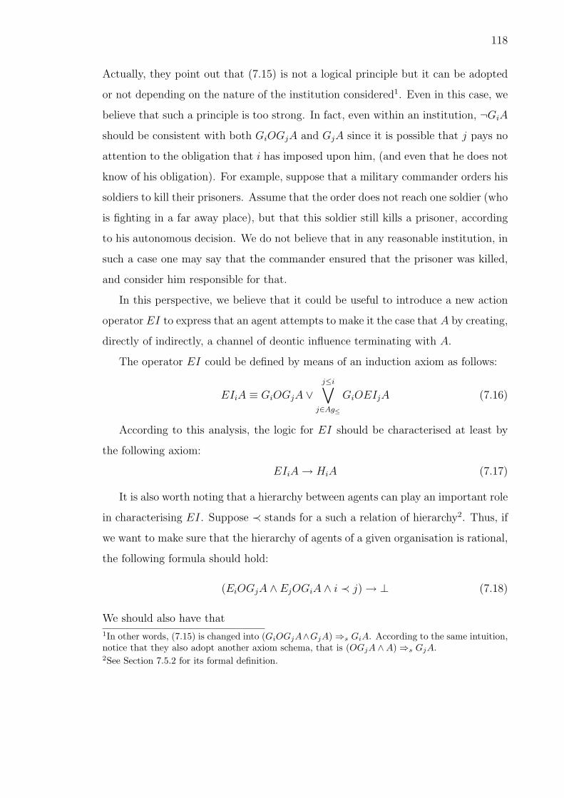
118
Actually, they point out that (7.15) is not a logical principle but it can be adopted
or not depending on the nature of the institution considered1. Even in this case, we
believe that such a principle is too strong. In fact, even within an institution, ¬GiA
should be consistent with both GiOGjA and GjA since it is possible that j pays no
attention to the obligation that i has imposed upon him, (and even that he does not
know of his obligation). For example, suppose that a military commander orders his
soldiers to kill their prisoners. Assume that the order does not reach one soldier (who
is fighting in a far away place), but that this soldier still kills a prisoner, according
to his autonomous decision. We do not believe that in any reasonable institution, in
such a case one may say that the commander ensured that the prisoner was killed,
and consider him responsible for that.
In this perspective, we believe that it could be useful to introduce a new action
operator EI to express that an agent attempts to make it the case that A by creating,
directly of indirectly, a channel of deontic influence terminating with A.
The operator EI could be defined by means of an induction axiom as follows:
EIiA ≡ GiOGjA ∨j≤i∨
j∈Ag≤
GiOEIjA (7.16)
According to this analysis, the logic for EI should be characterised at least by
the following axiom:
EIiA → HiA (7.17)
It is also worth noting that a hierarchy between agents can play an important role
in characterising EI. Suppose ≺ stands for a such a relation of hierarchy2. Thus, if
we want to make sure that the hierarchy of agents of a given organisation is rational,
the following formula should hold:
(EiOGjA ∧ EjOGiA ∧ i ≺ j) → ⊥ (7.18)
We should also have that1In other words, (7.15) is changed into (GiOGjA∧GjA) ⇒s GiA. According to the same intuition,notice that they also adopt another axiom schema, that is (OGjA ∧A) ⇒s GjA.2See Section 7.5.2 for its formal definition.

119
(EIiA ∧ EjOGiA ∧ i ≺ j) → ⊥ (7.19)
In other words, both explicit and implicit “circular” chains of deontic control are not
permitted.
7.4 The counts-as link
7.4.1 Jones and Sergot’s analysis
A. Jones and M. Sergot [Jon96] (abbreviated as JS in the following) have devel-
oped a formal approach to the notion of institutionalised power by introducing a new
conditional connective ‘⇒s’. Such a connective is intended to express the ‘counts
as’ connection holding in the context of an institution s as described, notably, by
Searle [Sea95]. In other words, when applied to action description, a conditional
A ⇒s B says that action A counts as action B. Notice that this is frequently used
in the law: when there is a set of rules which link a certain legal effect to action
(or situation) B, and the law wants the same effects to be linked also to a different
action (or situation) A, then the law says that A counts as B (for the purpose of the
achievement of those effects).
Following Chellas’ terminology [Che75], the logic provided by JS for ⇒s is a
classical (but not normal) conditional logic3. In addition, it is characterised by the
following axiom schemas:
((A ⇒s B) ∧ (A ⇒s C)) → (A ⇒s (B ∧ C)) (7.20)
((A ⇒s B) ∧ (C ⇒s B)) → ((A ∨ C) ⇒s B) (7.21)
and, possibly, by
(A ⇒s B) → ((B ⇒s C) → (A ⇒s C)) (7.22)
JS’s analysis is then integrated by introducing the normal KD modality Ds.
This is suggested to express all constraints on s among which the link ‘counts as’
3In other words, the logic for ⇒s contains the rules RCEA and RCEC but not RCM.

120
is included. In other words, DsA means that A is “recognised by the institution
s” [SCJ97]. Accordingly, it is adopted the following schema:
(A ⇒s B) → Ds(A → B) (7.23)
Besides the general meaning of Ds, one of the main consequences of Ds is to make
possible a restricted version of detachment of the consequent of ⇒s. In fact, by
accepting
(A ⇒s B) → (A → DsA) (7.24)
it can be derived that
(A ⇒s B) → (A → DsB) (7.25)
In other words, if A ⇒s B and A, then B should be the case in s, namely DsB.
7.4.2 A new proposal
In this section, we will provide a fresh characterisation of the counts-as connec-
tion that, though preserving most properties of the model of JS, adopts a different
perspective.
Rather than introducing a separate logic for the counts-as connection, and then
linking it with a Ds logic (relativised to the particular institution under considera-
tion), we use one conditional operator V to express any normative connections or
constants, in any institutions.
In addition, we will use the Ds operator as in [Jon96] but we will apply it to
the consequent of such conditional links, in order to relativise this consequent to
the particular institution under consideration. We argue that any institution can
only state what normative situation holds for itself, given certain conditions, but
according to a general type of conditionality. Actually, we can have different types
of facts between which a conditional link may hold with regard to an institution s:
(1) links between brute facts and s-facts (raising one’s hand is making a bid), (2)
links between s-facts and other s-facts (making a bid is a contractual offer) , (3) links

121
between s′-facts and s-facts, where s′ is an institution different from s (a catholic or
muslim marriage counts as a civil marriage).
By applying the Ds modality to the antecedents or to the consequents of our
conditionals we can easily express and clearly distinguish all those connections.
The logic for V contains besides classical propositional logic, the following axioms
A V A (7.26)
(A V B) ∧ (A ∧B V C) → (A V C) (7.27)
(A V B) ∧ (A V C) → (A ∧B) V C) (7.28)
(A V C) ∧ (B V C) → (A ∨B) V C) (7.29)
and is closed under the usual inference rules
A ≡ B
(A V C) → (B V C)(RCEA)
and(A1 ∧ · · · ∧ An) → B
(C V A1 ∧ · · · ∧ C V An) → (C V B)(RCK )
Let us give now a suitable characterisation of the “institutional modality” Ds. We
believe that the logic for such an operator should be closed under logical equivalence
and contain the following axiom schemas:
DsA → ¬Ds¬A (7.30)
(DsA ∧DsB) → Ds(A ∧B) (7.31)
Notice that we do not accept the necessitation rule. Since the intended meaning
of this modality is to express the domain of the institutional facts holding in a given
institution, the lack of necessitation is reasonable: it sounds strange that > is an
institutional fact for any institution s.
Finally, on the basis of V we can define a relativised operator Vs operator,
which behaves similarly to ⇒ of JS. For this purpose we need to combine a link

122
A V DsB from a brute fact to an institutional fact, and a link DsA V DsB from
an institutional fact to another institutional fact.
In this perspective, we state the following definition:
(A Vs B) =def (A V DsB) ∧ (DsA V DsB) (7.32)
7.4.3 A comparison
Let us now compare the behavior of our logic to the original proposal of JS. Let
us first focus on the commonalities.
Basically, the main commonality between the two approaches is that both al-
low for the detachment of institutional consequents from brute facts and count-as
conditionals: as in JS’s approach Ds(B) follows from A and A ⇒s B, according to
(7.24, and 7.25), so in our approach Ds(B) follows from A and A Vs B, according
to definition (7.32) (which implies A V Ds(B)) and inference rule (??). In addition,
we accepted for our definition of Vs a great part of the axiom schemas introduced
by JS for ⇒s. In particular theorems corresponding to axioms 7.20 and 7.21 can be
derived in our system, on the basis of definition 7.32.
Let us now consider the differences between the two systems.
One significant difference between our approach and JS’s system is that our
approach allows for non-monotonic reasoning. We believe that non-monotonicity
should be an essential property for the count-as link, but also in general for any
normative conditional. This is the reason why we would like to treat it in a uniform
way. Consider the following two examples.
In an auction if the agent i raises one hand, this may count as making a bid.
However, this does not hold if i raises one hand and scratches his own head. However,
we still want to have that “i’s raising one hand ‘counts as’ i’s making a bid” and the
fact that i raised one hand imply that i made a bid.
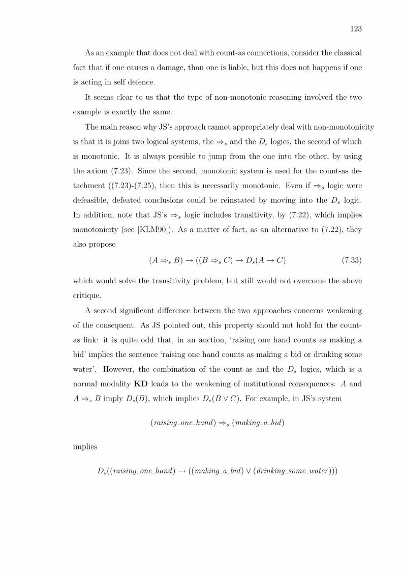
123
As an example that does not deal with count-as connections, consider the classical
fact that if one causes a damage, than one is liable, but this does not happens if one
is acting in self defence.
It seems clear to us that the type of non-monotonic reasoning involved the two
example is exactly the same.
The main reason why JS’s approach cannot appropriately deal with non-monotonicity
is that it is joins two logical systems, the ⇒s and the Ds logics, the second of which
is monotonic. It is always possible to jump from the one into the other, by using
the axiom (7.23). Since the second, monotonic system is used for the count-as de-
tachment ((7.23)-(7.25), then this is necessarily monotonic. Even if ⇒s logic were
defeasible, defeated conclusions could be reinstated by moving into the Ds logic.
In addition, note that JS’s ⇒s logic includes transitivity, by (7.22), which implies
monotonicity (see [KLM90]). As a matter of fact, as an alternative to (7.22), they
also propose
(A ⇒s B) → ((B ⇒s C) → Ds(A → C) (7.33)
which would solve the transitivity problem, but still would not overcome the above
critique.
A second significant difference between the two approaches concerns weakening
of the consequent. As JS pointed out, this property should not hold for the count-
as link: it is quite odd that, in an auction, ‘raising one hand counts as making a
bid’ implies the sentence ‘raising one hand counts as making a bid or drinking some
water’. However, the combination of the count-as and the Ds logics, which is a
normal modality KD leads to the weakening of institutional consequences: A and
A ⇒s B imply Ds(B), which implies Ds(B ∨ C). For example, in JS’s system
(raising one hand) ⇒s (making a bid)
implies
Ds((raising one hand) → ((making a bid) ∨ (drinking some water)))

124
In our system weakening of institutional consequences does not hold, since we
define Ds in terms a non-normal D modality without necessitation and axiom K,
thus avoiding that Ds is closed under logical consequence4.
In fact, the K schema was needed in JS’s approach to guarantee detachment of
institutional consequents through material implications modalised by Ds.
Obviously, because of the new characterisation of Ds and of our definition of the
count-as link, the adoption RCK for V is not problematic since it determines the
closure of V under logical consequence only when the consequent is not modalised
by Ds.
7.5 Proclamation and declarative power
On the basis of the notions introduced in the previous section, we will now analyse
a phenomenon which has a major importance in legal and similar institutions: this
is the decentralised intentional creation of new normative positions. We will first
describe the actions (i.e., proclamations) which maybe used to create those positions,
and then we will consider the institutional rules making those actions effective, and
finally we will analysis the power which these rules attribute (declarative power).
7.5.1 The notion of proclaiming
The idea of proclaiming is used to cover all those speech acts by which a subject
makes a statement expressing a certain proposition, and this statement has the
function (purpose, point or objective) of making this proposition true. So, we say
that one subject i proclaims that A when i makes a statement which expresses A,
and has the function of realising A.
Of course, a plethora of works have been put forward to give a formal account
of speech acts theory (see, e.g., [CP88, SV85, CL90]). More recently, a number of
4The reader who feels this choice unsatisfactory has a different option. It is enough to give up thenecessitation rule for Ds. In this way, axiom K can be retained, thus obtaining a quasi-normalsystem [Seg71, ch. 3]. However, this option will not be considered here.

125
different agent communication languages have been devised. Let us mention two of
the most popular approaches, that is FIPA ACL [fIPA] and KQLM [FFMM94].
In a great part of works on speech acts (see also [Jon90, CDJT99, Sin, Col00]),
what we model as proclamations is represented through different types of speech
acts (commissives, permissives, agreements, etc.), each one characterised by its own
specific semantics. On the contrary, we view all those performatives as instances of
just one speech act, since their differences, from our perspective, only pertain to the
content which is proclaimed. This provides a simpler framework for institutional
performatives. The framework is simpler since the logic of all institutional perfor-
matives is exhausted by the simple logic of the (modal) operator of proclaiming. In
this way, it is also permitted to easily combine speech acts with other formalisms
such as those described in the previous sections.
According to our analysis, the type of speech act we have so defined has some
interesting peculiarities.
First, note that it is neutral in regard to intention-based [Gri89] and non
intention-based theories of speech acts [Jon90]. By saying that the proclamation
that A has the function to achieve A we do not specify how the notion of function
is to be characterized: it may be determined by the intention of the speaker, by the
intention attributed to the speaker by its interlocutor, by a shared convention, by a
communication protocol, etc. What is sufficient, for our purpose, is that the act has
a word to world direction of fit [SV85], that is that has the function to change the
normative world to make it fit the content of the act.
Secondly, note that a proclamation is not necessarily effective (it does not nec-
essarily produce A). When the notion of function is interpreted with reference to
the intention of the speaker it necessarily involves an attempt to achieve A, but this
attempt may not be successful. Whether it is successful or not, within a certain
institutional context, depends on whether that institution makes it effective. It is
up to the institutional rules to establish whether i’s proclamation that A, in the
conditions in which it is made, produces A or not.
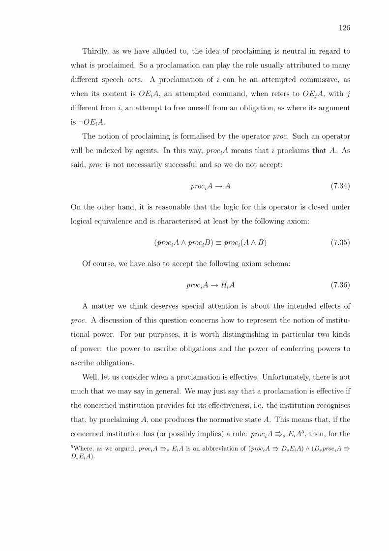
126
Thirdly, as we have alluded to, the idea of proclaiming is neutral in regard to
what is proclaimed. So a proclamation can play the role usually attributed to many
different speech acts. A proclamation of i can be an attempted commissive, as
when its content is OEiA, an attempted command, when refers to OEjA, with j
different from i, an attempt to free oneself from an obligation, as where its argument
is ¬OEiA.
The notion of proclaiming is formalised by the operator proc. Such an operator
will be indexed by agents. In this way, prociA means that i proclaims that A. As
said, proc is not necessarily successful and so we do not accept:
prociA → A (7.34)
On the other hand, it is reasonable that the logic for this operator is closed under
logical equivalence and is characterised at least by the following axiom:
(prociA ∧ prociB) ≡ proci(A ∧B) (7.35)
Of course, we have also to accept the following axiom schema:
prociA → HiA (7.36)
A matter we think deserves special attention is about the intended effects of
proc. A discussion of this question concerns how to represent the notion of institu-
tional power. For our purposes, it is worth distinguishing in particular two kinds
of power: the power to ascribe obligations and the power of conferring powers to
ascribe obligations.
Well, let us consider when a proclamation is effective. Unfortunately, there is not
much that we may say in general. We may just say that a proclamation is effective if
the concerned institution provides for its effectiveness, i.e. the institution recognises
that, by proclaiming A, one produces the normative state A. This means that, if the
concerned institution has (or possibly implies) a rule: prociA Vs EiA5, then, for the
5Where, as we argued, prociA Vs EiA is an abbreviation of (prociA V DsEiA) ∧ (DsprociA VDsEiA).

127
institution it holds that, by proclaiming that A, i produces A. In other words, for
the institution i’s proclamation that A counts as (or generates) i’s production of A.
Note that according to the action logic above presented, EiA implies A. Therefore
when a prociA is effective A should follow. When an institution provides for the
effectiveness of a proclamation to the effect that A, we say that the subject of the
proclamation has a declarative power with respect to A:
DeclPow iA =df prociA Vs EiA (7.37)
According to (7.37), if an agent i has the power over j to ascribe the obligation to
achieve A, the following formula holds:
prociOGjA Vs EiOGjA (7.38)
More generally, i’s power to ascribe an obligation also concern the creation of a
deontic channel according to a specific hierarchy. This means that i is empowered
to oblige other agents:
(prociOEIjA Vs EiOEIjA) (7.39)
It is immediate to see that the following formula can be proved from (7.39:
(prociOGjA Vs EIiA) (7.40)
On the other hand, i has the power to delegate the power to make it the case
that A if we have that
(proci(procjA Vs EjA)) Vs Ei(procjA Vs EjA) (7.41)
Thus we are ready to define the notion of power to delegate powers of ascribing
obligations. Following (7.41), this can be trivially done as follows:
(proci(procjOGkA Vs EjOGkA)) Vs Ei(procjOGkA Vs EjOGkA) (7.42)
or, more generally,
(proci(procjOEIkA Vs EjOEIkA)) Vs Ei(procjOEIkA Vs EjOEIkA) (7.43)

128
We may also have a kind of power, which includes both the power of conferring
a power creating a normative position (an obligation or its negation) and also the
power of transferring to others a similar power. We define this type as a sort of
recursive power RecDeclPow . It can be formalised following a similar idea as that
expressed in (7.16) for EI. In other words,
RecDeclPow i(OGkA) ≡
DeclPow i(OGkA) ∧ (
k≤j≤i∧j∈Ag≤
DeclPow i(RecDeclPow j(OGkA)))(7.44)
The above formula means that the holder i of the recursive declarative power is
enabled to exercise his power in two ways. The first capacity DeclPow i(OGkA),
enables i to make so that k is obliged to realize A. The second capacity
DeclPow i(RecDeclPow j(OGkA)) enables i to transfer to another agent j the same
recursive declarative power which i possesses. This latter notion is useful in those
cases in which an organization is extended over multiple levels, and the top level
wants to delegate not only the performance of the action, but also the command to
perform it.
7.5.2 Hierarchy among agents
As we have alluded to in the previous sections, to deal with the notion of power
we need to introduce an explicit relation of hierarchy ≺ among agents. How to
characterise ≺? In [DW95], for instance, it is suggested that the power relation
should correspond to a partial ordering on the class of agents.
This characterisation is too weak for our purposes. What about a total ordering?
It is clearly too strong: usually, an institution does not require that, for each pair
of agents, one is superior to the other. A reasonable condition is then that ≺ corre-
sponds to a total ordering with clusters. In other words, we have that, for every two
agents i and j such that
• i ∈ Agm and j ∈ Agn;

129
• Agm ⊆ Ag and Agn ⊆ Ag;
• Agm ∩ Agn = ∅;
either i ≺ j or j ≺ i.
It is worth noting that this ordering is also dependent on the operator proc and the
connective Vs. In particular, it seems to be intuitive to reformulate the declarative
power of an agent i to ascribe obligations DeclPower iOGjA by stipulating that
¬j ≺ i.
On the other hand, something stronger can be accepted. For instance, new
hierarchical relations between agents can be made explicit:
DeclPower iOGjA Vs i ≺ j (7.45)
We think that also (7.45) is quite reasonable. If an agent i has the power to ascribe
obligations to another agent j, this mean, at least defeasibly, that i is superior to
j. However, accepting (7.45) could raise some problems for a semantic treatment
of ≺. In fact, since we have the detachment for Vs, (7.45) permits to infer new
hierarchical relations between agents. How to deal with question?
As usual, an action can be conceived as a transition between two states. Ob-
viously, a speech act is a very special kind of action. In this perspective, we have
to consider the dynamic corresponding to institutionalised speech acts, in particular
proc whose argument is either an obligation (e.g., OA or OEjA) or an attribution of
power (e.g., i ≺ j). Those actions transform the state actual at the time of utterance
in a state where the content of the speech act holds. Semantically, we can analyse
this kind of acts by means of two dimension hierarchical fibred models. Shortly and
roughly a two dimensional hierarchical model is a possible world structure where the
points of the outer logic are models of the inner logic and the points are related by a
fibring function. For the application at hand we can adopt a revision function as the
fibring function of the model. In other words, each time we can detach i ≺ j from
DeclPower iOGjA Vs i ≺ j it is possible to define via the fibring function another
model where i ≺ j holds (see [GG98] for the technical details).

130
7.5.3 Empowering autonomous agents
A fundamental aspect of a norm-governed society consists in the allotment of
permissions and obligations to its members. This is the way in which such a society
restrains and organizes the actions of its members. However, in an autonomous
society (autonomous means establishing laws for one-self) the agents themselves
must be able of creating those permissions and obligations. The decisive aspect
of an autonomous social organization consists therefore in the empowerment of its
agents, that is in establishing how agents may create what normative relations. In
our model agents are empowered by attributing them appropriate declarative powers.
This should enable agents to create the normative relations they need, and in this
way to co-ordinate their behaviors. The failure to provide a viable allocation of such
powers may threaten the survival of society. For example, if each self interested
agents were given an unlimited power to unilaterally create obligation on the head
of other agents, society would soon collapse, since everybody would soon be covered
with an unsustainable workload, obligations would no longer be fulfilled, conflicts
would explode, and trust would fade away. In the following we will sketch some
features of a viable allocation of powers, which gives each agent the maximum of
power consistent with the attribution of the same power to other agents.
Multi-lateral Proclaims (Contracts)
A declarative power may be jointly exercised by more than one party. If so,
the proclamation will be an action performed by a set of agents. In very general
terms, we may call such an action a contract. For example the making of a contract
through which j takes the obligation towards k to provide a piece of music m and

131
k undertakes the obligation toward j to pay the price p, can be represented by the
following proclamation6:
proc{j,k}(OkE{j}(deliver(m)) ∧OjE{k}(pay(p))) (7.46)
Such joint proclaims are usually performed by two acts, the first of which is called
offer, and the second acceptance. This combination is considered as a joint declara-
tion (even when there is a delay between offer and acceptance). So we may want to
say that the combination of an offer and an acceptance counts as making a contract.
In cases where contracts are limited to the creation of reciprocal obligations we can
express this as follows:
offer {j},{k}(A, B) ∧ accept{j},{k}(A, B) V proc{j,k}(OkE{j}A ∧OjE{k}B) (7.47)
If j offers to k to make a contract with reciprocal obligations having content A and
B, and k accepts, this counts as making the contract. If the parties have the power
to make an effective contract, the joint declaration generates within the institution
the obligations for the parties involved in the contract:
D(OkE{j}A ∧OjE{k}B) (7.48)
where D is the “institutional” modality introduced in (7.32). The operators offer
and accept are two committing declarative acts, that can be defined using the non
committing declarative acts proposal and agree.
proposal{j},{k}(A, B) = proc{j}(OkE{j}A ∧OjE{k}B) (7.49)
proposal{j},{k} is a declaration of j where she proposes to ascribe to herself the
obligation towards k to do A, and to k the obligation towards herself to do B. On
6Notice that our reading is different from that proposed, e.g., by Herrestad and Krogh [HK95].They view a contract relation as follows: OiEiB ∧ OjEiB. The first conjunct is an ought-to-dostatement expressing that i has the obligation to do B; the second corresponds to an ought-to-bestatement saying that j requires i to perform B. We think this approach is intuitively unsatisfactorysince it lacks to make explicit a strong logical relation between the two conjuncts. We solve thisproblem by saying that the conjunction of directed obligations is proclaimed jointly by both parties.For a criticism of Herrestad and Krogh’s approach, see [TT99].
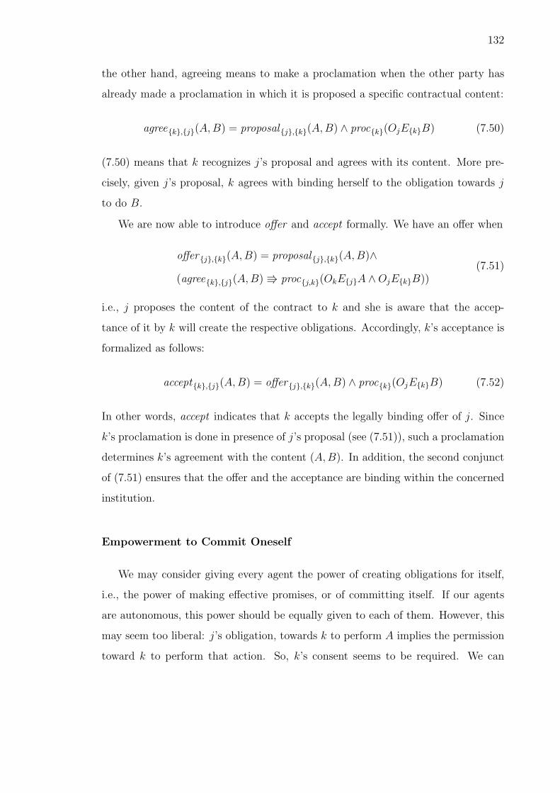
132
the other hand, agreeing means to make a proclamation when the other party has
already made a proclamation in which it is proposed a specific contractual content:
agree{k},{j}(A, B) = proposal{j},{k}(A, B) ∧ proc{k}(OjE{k}B) (7.50)
(7.50) means that k recognizes j’s proposal and agrees with its content. More pre-
cisely, given j’s proposal, k agrees with binding herself to the obligation towards j
to do B.
We are now able to introduce offer and accept formally. We have an offer when
offer {j},{k}(A, B) = proposal{j},{k}(A, B)∧
(agree{k},{j}(A, B) V proc{j,k}(OkE{j}A ∧OjE{k}B))(7.51)
i.e., j proposes the content of the contract to k and she is aware that the accep-
tance of it by k will create the respective obligations. Accordingly, k’s acceptance is
formalized as follows:
accept{k},{j}(A, B) = offer {j},{k}(A, B) ∧ proc{k}(OjE{k}B) (7.52)
In other words, accept indicates that k accepts the legally binding offer of j. Since
k’s proclamation is done in presence of j’s proposal (see (7.51)), such a proclamation
determines k’s agreement with the content (A, B). In addition, the second conjunct
of (7.51) ensures that the offer and the acceptance are binding within the concerned
institution.
Empowerment to Commit Oneself
We may consider giving every agent the power of creating obligations for itself,
i.e., the power of making effective promises, or of committing itself. If our agents
are autonomous, this power should be equally given to each of them. However, this
may seem too liberal: j’s obligation, towards k to perform A implies the permission
toward k to perform that action. So, k’s consent seems to be required. We can

133
propose a general rule attributing all agents the power of committing themselves to
other agents through a contract:
∀j, k (DeclPow{j,k}(OkE{j}A)) (7.53)
which means that every couple of agents has the power of establishing any obligation
between them, simply by proclaiming it. In other words, we empower all our agents
to make effective promises (with the consent of the promisee).
Empowerment to Remit Obligations and Give Permissions
It is reasonable to assign every agent j the power of freeing any other agent k
from obligations toward j, even without k’s consent. For example, if j is no longer
interested in k’s performance, j should be allowed to free k from that performance.
In fact, if j is able to look after itself and an obligation on k was originally created
to promote j’s interest, then j should be empowered to choose whether to cancel
that obligation or not:
∀j, k (DeclPow{j}(¬OjE{k}A) ∧DeclPow{j}(¬Oj¬E{k}A)) (7.54)
Accordingly, this formula also enables an agent to give any permission towards itself:
∀j, k (DeclPow{j}(PjE{k}A)) (7.55)
So, for example, if agent j has the obligation towards k not to access a certain piece of
information, k has the power of permitting that j accesses the information, according
to 7.55. This is a very libertarian approach, but is appropriate for autonomous
agents, e.g, in the commercial domain.
Empowerment to Command
It would be unreasonable to give all agents the power of commanding whatever
action to any other agent. The power of commanding needs to be restricted only to

134
specific cases, such as when one agent is hierarchically superior to another. A power
of commanding held by superiors over inferiors would be conferred by the following
rule7:
∀j, k (j ≺ k ⇒ DeclPow{j}(OjE{k}A)) (7.56)
where ≺ corresponds to a hierarchical relation between agents. Notice that ‘⇒’
stands for the generic normative connection we have alluded to. In many types
of societies, further restriction would be opportune, if the boss is not be a total
dictator over its subordinates. A total power of commanding may be, however, the
right empowerment for a human user over its agents.
Empowerment to Renounce to Power
It may seem reasonable to give agents also the power to renounce to their powers.
In general terms this would be expressed by the following general empowerment:
∀j (DeclPow{j}(¬DeclPow{j}A)) (7.57)
Empowerment to Empower
We give our agents a further chance to develop their societal relationships if we
give them the power of conferring a power. For example, the formula below expresses
the idea that j has the power of creating l’s power of creating the obligation that k
realizes A.
∀x (DeclPow{j}(DeclPow{l}(OxE{k}A))) (7.58)
What kinds of empowerment to empower can be allocated to our agents, according
to a general rule? A very liberal choice would consist in stating that each agent has
the power of giving other agents the powers he has for itself.
∀j, k (DeclPow{j}A ⇒ DeclPow{j}(DeclPow{k}A)) (7.59)
7For a formal treatment of hierarchies among agents in the current setting, see [GGRS02].

135
So, for example, since each agent j has the power of committing itself according
to (7.53), according to (7.59), j also has the power of submitting itself to another
agent k, giving k the power to commanding j. This will be done via the following
proclamation:
proc{j}(DeclPow{k}OkE{j}A) (7.60)
Note that according to the definition above, when j gives to k a power which was
previously possessed by j, j does not lose its power: both j and k can now exercise
it. Obviously, empowerment may lead to cycles. Agent j1 empowers j2 to A, . . . ,
agent jn empowers j1 to A. However, this is no problem: the latter empowerment
simply is redundant, since j already possessed that power (unless it has renounced
its power when conferring that power to another agent).
Recursive Empowerment
Finally, it is possible to confer our agents a further kind of power, which includes
both the power of conferring a power to create a normative position and also the
power of transferring to others a similar power. We define this type a recursive
declarative power (which is a special case of formula (53) in [GGRS02]):
RecDeclPow{j}(OjE{k}A) = DeclPow{j}(OjE{k}A) ∧
DeclPow{j}(RecDeclPow{l}(OjE{k}A)(7.61)
The above formula means that the holder j of the recursive declarative power is
enabled to exercise his power in two ways. The first capacity,
DeclPow{j}(OjE{k}A) (7.62)
enables j to make so that k is obliged to realize A. The second capacity
DeclPow{j}(RecDeclPow{l}(OjE{k}A)) (7.63)
enables j to transfer to another agent l the same recursive declarative power which j
possesses. This latter notion is useful in those cases where an organization is devel-
oped in multiple levels, and the top level wants to delegate not only the performance

136
of the action, but also the command to perform it. The exercise of this power may
lead to cycles, but again, this is no problem (the agent who started the cycle may
consider having another try), or better it is a problem that it is up to the concerned
agents to solve, according to their view of their own interest.
Specific Limitations to Empowerment
In the previous pages, we have sketched the constitution of a liberal, or better
a libertarian society, where every agent is considered to be fully able to look after
its interest, and where any normative relation can be created via the consent of the
interested parties. In many real life contexts, and in particular in legal institutions,
various limitations to individual freedom are provided, for a number of reasons:
preventing frauds, protecting the weaker party, preventing the parties from making
mistakes. Unfortunately, there is not much that we may say in general in regard
to such limitations. It depends on the particular institutional what exceptions are
made to the libertarian framework we sketched above. Consider, for example, the
regulations which require a proclamation to a certain effects to be performed in
certain specific ways (e.g., contracts concerning real estates have to be made in
writing, or through deeds, unilateral promises are binding only if they serve an
interest of the promisor, testaments have to be signed, etc.). We will not investigate
here those special conditions, nor the way in which our formalism need to be extended
to cope with them. This will be a matter of future research.
7.6 The framework applied to the contract net protocol
In this section, we show how the framework can formalize a well-known trading
scenario, the contract-net protocol. As informal specification of the contract-net
protocol we assume that proposed in [PKA01]. For short, a contractor sends a call
for proposal to a set of prospective workers. In general, some workers answer to the
proposal, by offering to do the job, some do not. Among the answers received by

137
the timeout, there be refusals and offers. At this stage, the contractor chooses the
best offer according to some parameters. Then, it accepts the offer of the winner
and rejects the others. The winner must perform the contracted task and inform the
contractor after the execution.
There are some constraints which govern the process of contracting. First, a
worker can only offer to accomplish a task which it is able to accomplish. Second, a
worker can only offer to accomplish a task which has been proposed to him. Third,
a contractor can only accept an offer when he has the resources for paying for the
price.
We may view these constraints in two ways. One perspective is to consider
them to introduce conditions for the validity (effectiveness) of contracts stipulated
between a contractor and a worker. This would mean that if the contractor has no
money, or the worker is unable, or the contract was not preceded by a proposal,
then the contract would be invalid. This would be an exception to our definition of
multi-lateral proclaims, namely that the joint declaration of the interested parties is
sufficient for the effectiveness of the contract.
In this representation we adopt a different approach. Those constraints express
obligations on the parties, which they may violate at their risk (incurring in possible
sanction) but which do not imply the ineffectiveness of their contracts. Note that
this is what happens in the law: the fact that a party is unable to execute a contract
determines the liability of that party (for failure to perform its contractual duties),
rather than the invalidity of the contract.
First, observe that the content of the contract (which is proposed, offered and ac-
cepted) is always OcE{w}performed(t)∧OwE{c}paid(p), which means that the worker
w undertakes, toward the contractor, the obligation to perform the task t, while the
contractor c undertakes, towards the worker w, the obligation of paying the price p.
We write cfpWc (X) to mean that contactor c calls for proposals (of making a
contract) having content X from any worker w ∈ W . Note that a call for pro-
posals is a special case of ‘proposal ’, as previously described, and corresponds to

138
proposal{c},{w}(X) for any w ∈ W . We write offer {w},{c}(X) to mean that worker
w offers contactor c to conclude a contract with content X. Similarly, we write
accept{c},{w}(X) to mean that contractor c accepts to conclude a contract with worker
w having content X.
Here is how we represent those constraints:
1. if a worker agent cannot perform a task, then it is not permitted to offer to
perform it8:
∀w, c, t ((worker(w) ∧ ¬can{w}(performed(t))) ⇒
¬P (offer {w},{c}(E{w}performed(t), E{c}paid(p))))(7.64)
2. if a task has not been proposed, a worker agent is not permitted to offer for it:
∀w, c (worker(w) ∧ ¬cfpWc (X) ⇒ ¬P (offer {w},{c}(X))) (7.65)
3. if a contractor agent cannot pay the price for which a worker has offered to
perform the task than it is not permitted to accept the offer:
∀c, w, t, p (contractor(c) ∧ ¬can{c}(paid(p)) ⇒
¬Pw(accept{c},{w}(E{w}performed(t), E{c}paid(p))))(7.66)
We can now move to show a typical sequence of messages (in our framework,
proclamations) that compose the contract net protocol. First the contractor issues
a proposal of a contract the terms of which state that the worker has the obligation
to print a copy of the book War and Peace (t) and the contractor has the obligation
to pay Euro 20 (p) for it.
cfpWc (E{w}performed(t), E{c}paid(p)) (7.67)
As a consequence, now, workers, who are able to print the book are allowed to make
offers. This assumes that what is not forbidden is allowed. Let us assume that
8The expression ‘can’ may be viewed as the operator Ability described in [Elg97].

139
worker w returns an offer, intended as a (possibly committing) counter-proposal to
(7.67):
offer {w},{c}(E{w}performed(t), E{c}paid(p′)) (7.68)
where p′ =15 Euro. Let us now assume that this is the best offer c has received, so
that it accepts it (this implies c’s agreement; see Section 4.2).
accept{c},{w}(E{w}performed(t), E{c}paid(p′)) (7.69)
From (7.68) and (7.69) the following is obtained (within the institution):
D(proc{c,w}(OcE{w}performed(t) ∧OwE{c}paid(p′))) (7.70)
This means that the parties have made a contract. The contract is effective according
to the general principles. In fact, according to the logical properties of proclamation,
(7.70) implies the following
D(proc{c,w}(OcE{w}performed(t)) ∧ proc{c,w}(OwE{c}paid(p′))) (7.71)
Finally, according to axioms (7.53) and (??) (see note ??)we obtain (within the
institution) that w is obliged to do the job and c is obliged to pay for it:
D(OcE{w}performed(t) ∧OwE{c}paid(p′)) (7.72)
Once the contractor agent has decided which offer fits its needs the most, he has also
to communicate his refusals to the losers w′ 9:
∀w′ (proposal{w′},{c}(E{w′}performed(t), E{c}paid(p′′)) ∧
proc{c}(¬Ow′E{c}paid(p′′)))(7.73)
7.7 Future developments: applications and computational issues
In this section we will briefly indicate two developments and applications of the
framework we have previously defined.
9The following formula expresses c’s disagreement. Its definition can be intuitively formulated fromthe formula (7.50).

140
A first aspect regards a possible and concrete application of the framework in the
in the area of Digital Rights Management (DRM), a field that has drawn attention
from both the scientific community and industry in the last few years. DRM is in-
tended as a pool of technologies for data security and protection, copyright protection
and access control. DRM addresses the management of digital resources, including
their publishing, manipulation and transferring. DRM is ultimately one key en-
abling technology for marketing intellectual products, such as music, images and
e-books, on the Internet [KGG+01]. As a first approach, we have already looked at
the eXtensible rights Markup Language (XrML), an XML-based grammar for spec-
ifying rights related to digital resources [xrm]: XrML is in fact an XML grammar
intended for terming licenses related to digital resources. Licenses establish which
rights are granted to which parties and the conditions by which digital resources
can be operated. Our first results are promising (see [GRS03,GR04a]). We have al-
ready provided a simple extension of the set of elements of XrML language to cover
some types of normative positions required by our logical framework. Subsequently,
a prototype, based on this extension, has been built using the JADE multi-agent
system platform [Boa04] (see [GR04a]). The result is a system that can be used to
make agents negotiate the exchange of goods. Although the system seems to be a
good test bed for some virtual marketplace scenarios, limitations of the system are
due to the nature of XrML: every concept contained in a license must be understood
by the counterparts in the negotiation and this implies that every XrML tag must
be explicitly dealt with the parser. The future work will thus focus on devising a
suitable inference engine, so that agents can reason about rules reaching a more
flexible behavior. This should also permit to embed into the language and express
more complex normative concepts than those already added to standard XrML.
A second line of research consists in developing a computational framework, based
on the logical intuitions we have described here, and which should be able to treat
the basic mechanisms of institutional agency and normative co-ordination. Also in
this regard we have some first, but interesting, results. We have already proposed a

141
computationally oriented model based on Defeasible Logic. Defeasible logic has been
developed by Nute [Nut94] with a particular concern about computational efficiency
and developed over the years by [ABGM00]. The reason being ease of implementa-
tion, flexibility [ABGM00] (it has a constructively defined and easy to use proof the-
ory which allows us to capture a number of different intuitions of non-monotonicity)
and it is efficient: it is possible to compute the complete set of consequences of a given
theory in linear time. At the moment, we have provided two extensions of standard
Defeasible Logic. The first incorporates the notions of “counts as” and agency, the
second combines agency, BDI concepts and obligations [GR04b]. Our future work
will be devoted to developing a unique framework which is able to deal with the cog-
nitive component (BDI concepts), agency, and normative notions (“counts as” and
deontic operators). In addition, thanks to the nice computational features of the
logic, we plan to investigate how the framework can lead to real implementations.

142
Conclusions
Throughout the thesis we tackled issues related to multi-agent systems implementa-
tion.
We first draw attention to how such systems could be modeled, proposing a
possible extension to UML, a popular notation for designing software systems. This
approach has two advantages in our opinion: it builds up on existing knowledge, thus
facilitating the learning of AUML and it does not rely on any specific underlying
methodology, making the notation adoptable in many situations.
We then discussed the implementation of two projects, namely Wink and Sewasie,
where multi-agent systems were developed to meet the application requirements. The
purposes was to test agent technology on the field, using state-of-the-art tools (such
as JADE). This experience has suggested improvements and limitations of agent
technology, making us understand what gaps should be filled next. In particular we
consider interoperability, high-level communication and mobility strong features of
agents, which really make possible the construction of more advanced information
systems. Drawbacks are to be considered in the number and quality of tools available.
At the same time, we studied how to add features like for instance persistence support
(at testing level) and the concept of shadow agents, which may easy multi-agent
system development. We hope also that, as the experiences were conducted while
the agent specifications were under discussion in the scientific community, that our
work may have served as testbed for the discussion.
Finally, we tackled also the deployment of software agents in settings where they
will represent persons, i.e. software agents will be legally bounded to persons. This
is again another facet of agent technology. According to our view this could be

143
realized some day only if there is a precise legal framework within which to ascribe
agent interactions.
Future work comprises many directions among which we would give priority to (i)
investigating fields of application of agent technology outside integration information
systems, like sensor networks and data stream management systems and (ii) design
and build application where the agent middleware is coupled with inference engines
with the aim of providing more intelligent solutions and systems.
144
Bibliography
Chapter 2
[Aus62] J. L. Austin. How to Do Things with Words. Harvard University Press,Cambridge, Massachussets, USA, 1962.
[Boo94] G. Booch. Object-Oriented Analysis And Design With Application.Addison-Wesley, 2nd edition, 1994.
[Con] World Wide Web Consortium.
[dL96] Mark d’Inverno and Michael Luck. Formalising the contract net as agoal-directed system. In Proceedings of the 7th European workshop onModelling autonomous agents in a multi-agent world : agents breakingaway, pages 72–85. Springer-Verlag New York, Inc., 1996.
[FFMM94] T. Finin, R. Fritzson, D. McKay, and R. McEntire. KQML as an AgentCommunication Language. In N. Adam, B. Bhargava, and Y. Yesha,editors, Proceedings of the 3rd International Conference on Informationand Knowledge Management (CIKM’94), pages 456–463, Gaithersburg,MD, USA, 1994. ACM Press.
[FG97] Stan Franklin and Art Graesser. Is it an agent, or just a program?:A taxonomy for autonomous agents. In Proceedings of the Workshopon Intelligent Agents III, Agent Theories, Architectures, and Languages,pages 21–35. Springer-Verlag, 1997.
[HR95] Barbara Hayes-Roth. An architecture for adaptive intelligent systems.Artif. Intell., 72(1-2):329–365, 1995.
[Ld95] Michael Luck and Mark d’Inverno. A formal framework for agencyand autonomy. In Victor Lesser and Les Gasser, editors, Proceedingsof the First International Conference on Multi-Agent Systems (ICMAS-95), pages 254–260, San Francisco, CA, USA, 1995. AAAI Press.
[Mae95] Pattie Maes. Artificial life meets entertainment: lifelike autonomousagents. Commun. ACM, 38(11):108–114, 1995.
[New82] A. Newell. The knowledge level. Artificial Intelligence, 18:87–127, 1982.
[OPB00] J. Odell, H. Parunak, and B. Bauer. Extending uml for agents, 2000.
[Pit04a] Jeremy Pitt, editor. The Open Agent Socieites, chapter Cristiano Castel-franchi and Rino Falcone. Social Trust Theory. John Wiley and Sons,2004.
145
[Pit04b] Jeremy Pitt, editor. The Open Agent Socieites, chapter Cristiano Castel-franchi and Rino Falcone. Adjustable Social Autonomy. John Wiley andSons, 2004.
[RN03] St. Russell and P. Norvig. Artificial Intelligence - A Modern Approach.Prentice Hall International Series in Artificial Intelligence. Prentice Hall,2003. RUS s 03:1 1.Ex.
[Sea69] J. Searle. Speech Acts: An Essay in the Philosophy of Language. Cam-bridge University Press, Cambridge, Massachussets, USA, 1969.
[WJK00] Michael Wooldridge, Nicholas R. Jennings, and David Kinny. The gaiamethodology for agent-oriented analysis and design. Autonomous Agentsand Multi-Agent Systems, 3(3):285–312, 2000.
Chapter 3
[Arg79] Tilak Argewala. Putting petri nets to work. Computer, pages 85–94,1979.
[Bau02] Bernhard Bauer. Uml class diagrams revisited in the context of agent-based systems. In Revised Papers and Invited Contributions from theSecond International Workshop on Agent-Oriented Software Engineer-ing II, pages 101–118. Springer-Verlag, 2002.
[Ber] Sonia Bergamaschi. Experiencing auml for the wink multi-agent.
[BGGV03a] S. Bergamaschi, G. Gelati, F. Guerra, and M. Vincini. Experiencingauml for the wink milti-agent system,. In Proceedings AIIA and TABOOWorkshop: From Object to Agents (WOA03), 10-11 Settembre 2003,Villasimius, 2003.
[BGGV03b] S. Bergamaschi, G. Gelati, F. Guerra, and M. Vincini. Wink: a web-based enterprise system for collaborative project management in virtualenterprises. In Proceedings 4th International Conference on Web In-formation Systems Engineering (WISE), Roma Italy, 10-12 December2003, 2003.
[BMO00] B. Bauer, J. Muller, and J. Odell. An extension of uml by protocols formultiagent interaction, 2000.
[Boo94] G. Booch. Object-Oriented Analysis And Design With Application.Addison-Wesley, 2nd edition, 1994.
[BTS+04] Mihai Boicu, Gheorghe Tecuci, Bogdan Stanescu, Dorin Marcu, marcelBarbulescu, and Cristina Boicu. Design principles for learning agents.In Proceedings of the AAAi-04 Workshop on Intelligent Agent Architec-tures: Combining the Strengths of Software Engineering and CognitiveSystems. AAAI Press, 2004.
[CCF+99] R. Cost, Y. Chen, T. Finin, Y. Labrou, and Y. Peng. Modeling agentconversations with colored petri nets. In Working Notes of the Work-shop on Specifying and Implementing Conversation Policies, pages 59–66, Seattle, Washington, May 1999.

146
[CCF+00] Rost S. Cost, Ye Chen, Tim Finin, Yannis Labrou, and Yun Peng.Using colored petri nets for conversation modeling. In Frank Dignumand Mark Greaves, editors, Issues in Agent Communication, pages 178–192. Springer-Verlag: Heidelberg, Germany, 2000.
[Dem95] Y. Demazeau. From interactions to collective behaviour in agent-basedsystems, 1995.
[dL96] Mark d’Inverno and Michael Luck. Formalising the contract net as agoal-directed system. In Proceedings of the 7th European workshop onModelling autonomous agents in a multi-agent world : agents breakingaway, pages 72–85. Springer-Verlag New York, Inc., 1996.
[fIPA] Foundation for Intelligent Physical Agents.
[FO00] K Fernandes and Michel Occello. A recursive approach to build hybridmulti-agent systems. In Proceedings of the III Iberoamerican Work-shop on Distributed Artificial Intelligence and MultiAgent Systems,SBIA/IBERAMIA. LNAI Springer-Verlag, 2000.
[FW94] M. Fisher and M. Wooldridge. Specifying and executing protocols forcooperative action. In Proceedings of International Working Conferenceon Cooperating Knowledge-Based Systems (CKBS), Keele, U.K., 1994.
[Gro] Object Management Group.
[HK98] T. Holvoet and T. Kielmann. Behaviour specification of parallel activeobjects. Parallel Computing, 24(7):1107–1135, 1998.
[Hol91] Gerard J. Holzmann. Design and validation of computer protocols.Prentice-Hall, Inc., 1991.
[Hol95] Tom Holvoet. Agents and petri nets. Petri Net Newsletter, (49):3–8,October 1995.
[Hug02a] M. Huget. Agent uml class diagrams revisited, 2002.
[Hug02b] M. Huget. Extending agent uml protocol diagrams, 2002.
[IGCGV98] Carlos Argel Iglesias, Mercedes Garijo, Centeno-Gonzalez, and Juan R.Velasco. Analysis and design of multiagent systems using mas-commonkads. In Proceedings of the 4th International Workshop on IntelligentAgents IV, Agent Theories, Architectures, and Languages, pages 313–327. Springer-Verlag, 1998.
[IGG99] Carlos Iglesias, Mercedes Garrijo, and Jose Gonzalez. A survey ofagent-oriented methodologies. In Jorg Muller, Munindar P. Singh, andAnand S. Rao, editors, Proceedings of the 5th International Workshopon Intelligent Agents V : Agent Theories, Architectures, and Languages(ATAL-98), volume 1555, pages 317–330. Springer-Verlag: Heidelberg,Germany, 1999.
[Jen92] Kurt Jensen. Coloured Petri Nets. Basic Concepts, Analysis Methods,and Practical Use, volume 1. Springer Verlag, 1992.
[Jen94] Kurt Jensen. Coloured Petri Nets. Basic Concepts, Analysis Methods,and Practical Use, volume 2. Springer Verlag, 1994.
[Jen97] Kurt Jensen. Coloured Petri Nets. Basic Concepts, Analysis Methods,and Practical Use, volume 3. Springer Verlag, 1997.

147
[KIO95] Kazuhiro Kuwabara, Toru Ishida, and Nobuyasu Osato. Agentalk:Coordination protocol description for multiagent systems. In VictorLesser, editor, Proceedings of the First International Conference onMulti–Agent Systems, page 455, San Francisco, CA, 1995. MIT Press.
[MKC01] John Mylopoulos, Manuel Kolp, and Jaelson Castro. UML for agent-oriented software development: The tropos proposal. Lecture Notes inComputer Science, 2185:422–??, 2001.
[Mod03a] FIPA TC Modeling. Fipa modeling: Interaction diagrams, 2003.
[Mod03b] FIPA TC Modeling. Fipa specification class diagrams, 2003.
[MW97] Daniel Moldt and Frank Wienberg. Mulit-agent systems based oncoloured petri nets. In Proceedings of the 18th International Confer-ence on Application and Theory of Petri Nets (IACATPN-97), volume1248, pages 82–101. Springer-Verlag: Lecture Notes in Computer Sci-ence, 1997.
[Ode02] James Odell. Agent and objects compared. Journal of Object Technol-ogy, 1(1):41–53, 2002.
[OPB00] J. Odell, H. Parunak, and B. Bauer. Extending uml for agents, 2000.
[PC96] Martin Purvis and Stephen Cranefield. Agent modelling with petri nets.In Proceedings of the Symposium on Discrete Events and ManufacturingSystems, pages 602–607. IEEE-SMC, 1996.
[Pet81] James Lyle Peterson. Petri Net Theory and the Modeling of Systems.Prentice Hall PTR, 1981.
[Smi80] R. G. Smith. The contract net protocol: High-level communicationand control in a distributed problem solver. IEEE Transactions onComputers, 29(12), 1980.
[Spi89] J. M. Spivey. The Z notation: a reference manual. Prentice-Hall, Inc.,1989.
[SW00] Gurdip Singh and Jun Wu. Modular object-oriented design of dis-tributed protocols. In Proceedings of the International Conferenceon Technology for Object Oriented Languages and Systems (TOOLS).IEEE Press, 2000.
[WJK00] Michael Wooldridge, Nicholas R. Jennings, and David Kinny. Thegaia methodology for agent-oriented analysis and design. AutonomousAgents and Multi-Agent Systems, 3(3):285–312, 2000.
Chapter 4
[Boa04] Jade Board. Jade security guide, 2004.[Bri01] Chris Britton. IT architectures and middleware: strategies for building
large, integrated systems. Addison-Wesley Longman Publishing Co., Inc.,2001.
[DSW97] K. Decker, K. Sycara, and M. Williamson. Middle-agents for the internet.In Proceedings of the 15th International Joint Conference on ArtificialIntelligence, Nagoya, Japan, 1997.
[FIP02] FIPA. Fipa subscribe interaction protocol specification, 2002.

148
[fIPA] Foundation for Intelligent Physical Agents.[fIPA02a] Foundation for Intelligent Physical Agents. Fipa abstract architecture
specification, 2002.[fIPA02b] Foundation for Intelligent Physical Agents. Fipa request interaction pro-
tocol specification, 2002.[fIPA04] Foundation for Intelligent Physical Agents. Fipa agent management spec-
ification, 2004.[For82] C. L. Forgy. Rete: A fast algorithm for the many pattern/many object
pattern match problem. Artificial Intelligence, 19:17–37, 1982.[FPV98] Alfonso Fuggetta, Gian Pietro Picco, and Giovanni Vigna. Understanding
Code Mobility. IEEE Transactions on Software Engineering, 24(5):342–361, 1998.
[GHB00] Mark Greaves, Heather Holmback, and Jeffrey Bradshaw. What is aconversation policy? In Issues in Agent Communication, pages 118–131.Springer-Verlag, 2000.
[Mye02] Judith M. Myerson. The Complete Book of Middleware. Auerbach, 2002.[NAS84] NASA. C language integrated production system, 1984.[RN03] St. Russell and P. Norvig. Artificial Intelligence - A Modern Approach.
Prentice Hall International Series in Artificial Intelligence. Prentice Hall,2003. RUS s 03:1 1.Ex.
[SCB+98] I. Smith, P. Cohen, J. Bradshaw, M. Greaves, and H. Holmback. Design-ing conversation policies using joint intention theory, 1998.
[SCS94] David Canfield Smith, Allen Cypher, and Jim Spohrer. Kidsim: pro-gramming agents without a programming language. Commun. ACM,37(7):54–67, 1994.
[SPVG01] Katia Sycara, Massimo Paolucci, Martin Van Velsen, and Joseph AndrewGiampapa. The retsina mas infrastructure. Technical Report CMU-RI-TR-01-05, Robotics Institute, Carnegie Mellon University, Pittsburgh,PA, March 2001.
[SR96] S.L. Star and K. Ruhleder. Steps toward an ecology infrastructure: Designand access for large information spaces. Information Systems Research,7(1):111–134, 1996.
[SS00] Onn Shehory and Katia Sycara. The RETSINA communicator. In CarlesSierra, Maria Gini, and Jeffrey S. Rosenschein, editors, Proceedings of theFourth International Conference on Autonomous Agents, pages 199–200,Barcelona, Catalonia, Spain, 2000. ACM Press.
[WS00] H. Wong and K. Sycara. A taxonomy of middle-agents for the internet,2000.
[ZMM99] Giorgos Zacharia, Alexandros Moukas, and Pattie Maes. Collabora-tive reputation mechanisms in electronic marketplaces. In Proceedingsof the Thirty-second Annual Hawaii International Conference on SystemSciences-Volume 8, page 8026. IEEE Computer Society, 1999.
Chapter 5
[BBGV01] Domenico Beneventano, Sonia Bergamaschi, Francesco Guerra, and Mau-rizio Vincini. The MOMIS approach to information integration. In ICEIS(1), pages 194–198, 2001.

149
[BCBV01] S. Bergamaschi, S. Castano, D. Beneventano, and M. Vincini:. Seman-tic integration of heterogeneous information sources. Special Issue onIntelligent Information Integration, Data and Knowledge Engineering,36(1):215–249, 2001.
[BSBV97] Sonia Bergamaschi, Claudio Sartori, Domenico Beneventano, and Mau-rizio Vincini. Odb-tools: A description logics based tool for schemavalidation and semantic query optimization in object oriented databases.In AI*IA ’97: Proceedings of the 5th Congress of the Italian Associationfor Artificial Intelligence on Advances in Artificial Intelligence, pages435–438. Springer-Verlag, 1997.
[CAdV01] Silvana Castano, Valeria De Antonellis, and Sabrina De Capitanidi Vimercati. Global viewing of heterogeneous data sources. IEEE Trans-actions on Knowledge and Data Engineering, 13(2):277–297, 2001.
[Con] World Wide Web Consortium.
[EM03] J. Roberto Evaristo and Bjørn Erik Munkvold. Collaborative infras-tructure formation in virtual projects. Journal of Global InformationTechnology Management, 6(2):9–47, 2003.
[Fel98] Christiane Fellbaum, editor. WordNet An Electronic Lexical Database.MIT Press, 1998.
[WZ99] Lutz Wegner and Christian Zirkelbach. Collaborative project manage-ment with a web-based database editor. In Proceedings of the Fifth In-ternational Workshop on Multimedia INformaiton Systems, 1999.
Chapter 6
[Con03] The Sewasie Consortium. Techniques for query reformulation, 2003.
[Con04] The Sewasie Consortium. Specification of agent technology for negotiationsupport, 2004.
[DS88] Randall Davis and Reid G. Smith. Negotiation as a metaphor for dis-tributed problem solving. pages 333–356, 1988.
[fIJ] Hibernate Relational Persistence for Idiomatic Java.http://www.hibernate.org/.
[fIPA02] Foundation for Intelligent Physical Agents. Fipa request interaction proto-col specification, 2002.
[MyS] MySql. http://www.mysql.org/.
[Sol] SolarMetric. http://www.solarmetric.com/.
[Wie92] G. Wiederhold. Mediators in the architecture of future information systems.IEEE Computer, 25:38–49, 1992.
[WS00] H. Wong and K. Sycara. A taxonomy of middle-agents for the internet,2000.
150
Chapter 7
[ABGM00] Grigoris Antoniou, David Billington, Guido Governatori, and Michael J.Maher. A flexible framework for defeasible logics. CoRR, cs.AI/0003013,2000.
[APS02] Alexander Artikis, Jeremy Pitt, and Marek Sergot. Animated specifi-cations of computational societies. In AAMAS ’02: Proceedings of thefirst international joint conference on Autonomous agents and multia-gent systems, pages 1053–1061. ACM Press, 2002.
[Boa04] Jade Board. jade.cselt.it/, 2004.
[Bou94] Craig Boutilier. Toward a logic for qualitative decision theory. In JonDoyle, Erik Sandewall, and Pietro Torasso, editors, Principles of Knowl-edge Representation and Reasoning, pages 75–86, 1994.
[CD00] Rosaria Conte and Chris Dellarocas, editors. Social Order in MultiagentSystems: Workshop on Norms and Institutions in Multi-Agent Systems(Held in conjunction with Autonomous Agents’2000), Boston, KluwerAcademic Publishers, 2000.
[CDJT99] Cristiano Castelfranchi, Frank Dignum, Catholijn M. Jonker, and JanTreur. Deliberative normative agents: Principles and architecture. InAgent Theories, Architectures, and Languages, pages 364–378, 1999.
[Che75] B.F. Chellas. Basic conditional logic. Journal of Philosophical Logic,1975.
[CL90] P. R. Cohen and H. J. Levesque. Rational interaction as the basis forcommunication. In P. R. Cohen, J. Morgan, and M. E. Pollack, editors,Intentions in Communication, pages 221–255. MIT Press, Cambridge,MA, 1990.
[Col00] M. Colombetti. A commitment–based approach to agent speech acts andconversations. In In Proc. Workshop on Agent Languages and Commu-nication Policies, 4th International Conference on Autonomous Agents(Agents 2000), pages 21–29, Barcelona, Spain, 2000.
[CP88] Philip R. Cohen and C. Raymond Perrault. Elements of a plan-basedtheory of speech acts. Distributed Artificial Intelligence, pages 169–186,1988.
[DW95] F. Dignum and H. Weigand. Communication and deontic logic, 1995.
[Elg97] D. Elgesem. The modal logic of agency. Journal of Philosophical Logic,2(2):1–46, 1997.
[FFMM94] T. Finin, R. Fritzson, D. McKay, and R. McEntire. KQML as an AgentCommunication Language. In N. Adam, B. Bhargava, and Y. Yesha,editors, Proceedings of the 3rd International Conference on Informationand Knowledge Management (CIKM’94), pages 456–463, Gaithersburg,MD, USA, 1994. ACM Press.
[fIPA] Foundation for Intelligent Physical Agents.

151
[GG98] Dov Gabbay and Guido Governatori. Dealing with label dependent deon-tic modalities. In P. McNamara, editor, Norms, Logics and InformationSystems. New Studies on Deontic Logic and Computer Science, Deon’98.IOS Press, 1998.
[GG02] D. Gabbay and F. Guenthner, editors. Handbook of Philosophical Logic(2nd edition), volume 8, chapter Deontic logic and contrary-to-duties,pages 265–343. Kluwer Academic Publishers, Dordrecht, Holland, 2002.
[GGRS02] G. Gelati, G. Governatori, A. Rotolo, and G. Sartor. Actions, institu-tions, powers. a logical framework. In Proceedings of the InternationalWorkshop on Regulated Agent-Based Social Systems: Theories and Ap-plications 2002 Workshop, pages 69–79, 2002.
[GR04a] G. Gelati and R. Riveret. Drm in a multi-agent system marketplace. InProceedings of the Law for electronics Agents LEA 2004, 2004.
[GR04b] Guido Governatori and Antonino Rotolo. Defeasible logic: Agency, in-tention and obligation. In DEON, pages 114–128, 2004.
[Gri89] H. Paul Grice. Studies in the Way of Words. Harvard University Press,Cambridge, 1989.
[GRS03] G. Gelati, A. Rotolo, and G. Sartor. A logic based analysis of xrml. InProceedings of the Law for electronics Agents LEA 2003, 2003.
[HK95] Henning Herrestad and Christen Krogh. Obligations directed from bear-ers to counterparts. In ICAIL ’95: Proceedings of the fifth internationalconference on Artificial intelligence and law, pages 210–218. ACM Press,1995.
[JK01] A.J.I. Jones and Ch. Krogh, editors. A Logical Framework. Basic andComposite notions for Reasoning about Norm, Action in Artificial Soci-eties. ALFEBIITE Deliverable D2, 2001.
[Jon90] A. I. J. Jones. Towards a formal theory of communication and speechacts. In P. R. Cohen, J. Morgan, and M. E. Pollack, editors, Intentionsin Communication, Cambridge, MA, 1990. MIT Press.
[Jon96] Cliff Jones. Formal methods light. ACM Computing Surveys,28(4es):121–121, 1996.
[KGG+01] K. Kamyab, F. Guerin, Goulev, P., and E. Mamdani. Designing agentsfor a virtual marketplace. AISB Journal, 1(1):61–85, 2001.
[KLM90] Sarit Kraus, Daniel Lehmann, and Menachem Magidor. Nonmonotonicreasoning, preferential models and cumulative logics. Artif. Intell., 44(1-2):167–207, 1990.
[LN04] Alessio Lomuscio and Donald Nute, editors. Proceedings of Deontic Logicin Computer Science 7th International Workshop on Deontic Logic inComputer Science, DEON 2004, Madeira, Portugal, 2004. Lecture Notesin Computer Science, Lecture Notes in Artificial Intelligence, Vol. 3065.
152
[MCT01] Dastani M.M., Jonker C.M., and J. Treur. A requirement specificationlanguage for configuration dynamics of multi-agent system. In Proceed-ings of the 2nd International Workshop on Agent-Oriented Software En-gineering, AOSE’01, Berlin, Germany, 2001. Springer Verlag.
[MW93] J.-J. C. Meyer and R. J. Wieringa. Deontic logic: A concise overview. InJ.-J. C. Meyer and R. J. Wieringa, editors, Deontic Logic in ComputerScience: Normative System Specification, pages 3–16. Wiley, New York,1993.
[Nut94] D. Nute. Defeasible logic. In D. M. Gabbay, C. J. Hogger, andJ. A. Robinson, editors, Handbook of Logic in Artificial Intelligenceand Logic Programming-Nonmonotonic Reasoning and Uncertain Rea-soning(Volume 3), pages 353–395. Clarendon Press, Oxford, 1994.
[PKA01] Jeremy Pitt, Lloyd Kamara, and Alexander Artikis. Interaction pat-terns and observable commitments in a multi-agent trading scenario. InAGENTS ’01: Proceedings of the fifth international conference on Au-tonomous agents, pages 481–488. ACM Press, 2001.
[RG91] Anand S. Rao and Michael P. Georgeff. Modeling rational agents withina BDI-architecture. In James Allen, Richard Fikes, and Erik Sandewall,editors, Proceedings of the 2nd International Conference on Principlesof Knowledge Representation and Reasoning (KR’91), pages 473–484.Morgan Kaufmann publishers Inc.: San Mateo, CA, USA, 1991.
[Roy00] L. Royakkers. Combining deontic and action logics for collective agency.In J. Breuker et al., editor, In Legal Knowledge and Information Systems(Jurix 2000). IOS Press, Amsterdam, 2000.
[SC96] Filipe Santos and Jose Carmo. Indirect action, influence and responsi-bility. In DEON, pages 194–215, 1996.
[SCJ97] F. Santos, J. Carmo, and A. Jones. Action concepts for describing or-ganised interaction. In R. A. Sprague, editor, Thirtieth Annual HawaiInternational Conference on System Sciences, pages 373–382, 1997.
[Sea95] J.R. Searle. The Construction of Social Reality. Penguin Press, Har-mondsworth, 1995.
[Seg71] K. Segerberg. An Essay in Classical Modal Logic. Filosofiska studier,Uppsala, 1971.
[Sin] M. Singh. An ontology for commitments in multiagent systems: Towarda unification of normative concepts.
[SV85] J.R Searle and D. Vanderveken. Foundations of Illucutionary Logic.Cambridge University Press, Cambridge, 1985.
[TT99] Y.H. Tan and W. Thoen. A logical model of directed obligations andpermissions to support electronic contracting. International Journal ofElectronic Commerce, 3:87–104, 1999.
[xrm] xrml.org. Xrml specification.
[ZK92] K. Zweigert and H. Kotz. Introduction to Comparative Law. Clarendon,Oxford, 1992.