agilent 34410a/34411a 61 2 digit high-performance multimeters · agilent 34410a/34411a 61/ 2 digit...
TRANSCRIPT
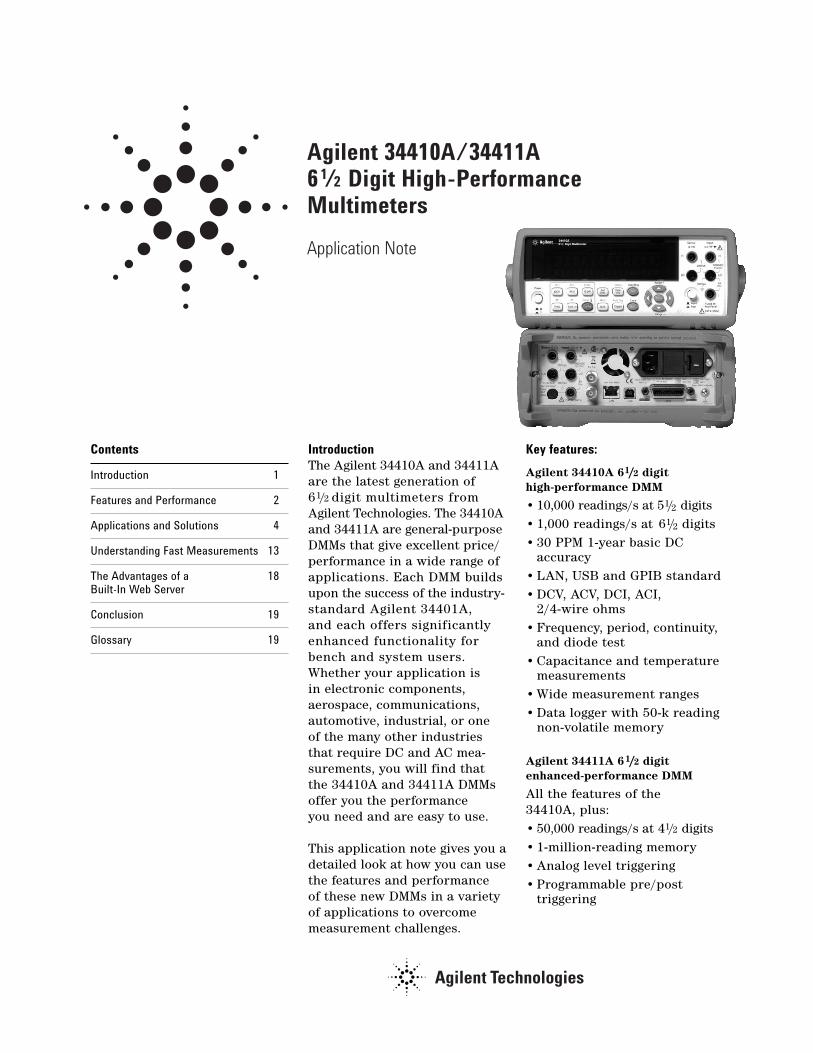
Agilent 34410A/34411A 6 1/2 Digit High-Performance Multimeters
Application Note
Contents
Introduction 1
Features and Performance 2
Applications and Solutions 4
Understanding Fast Measurements 13
The Advantages of a 18Built-In Web Server
Conclusion 19
Glossary 19
IntroductionThe Agilent 34410A and 34411Aare the latest generation of 61/2 digit multimeters fromAgilent Technologies. The 34410Aand 34411A are general-purposeDMMs that give excellent price/performance in a wide range ofapplications. Each DMM buildsupon the success of the industry-standard Agilent 34401A, and each offers significantlyenhanced functionality forbench and system users.Whether your application is in electronic components, aerospace, communications,automotive, industrial, or one of the many other industriesthat require DC and AC mea-surements, you will find thatthe 34410A and 34411A DMMs offer you the performance you need and are easy to use.
This application note gives you adetailed look at how you can usethe features and performance of these new DMMs in a varietyof applications to overcomemeasurement challenges.
Key features:
Agilent 34410A 61/2 digithigh-performance DMM
• 10,000 readings/s at 51/2 digits• 1,000 readings/s at 61/2 digits• 30 PPM 1-year basic DC
accuracy• LAN, USB and GPIB standard• DCV, ACV, DCI, ACI,
2/4-wire ohms• Frequency, period, continuity,
and diode test• Capacitance and temperature
measurements• Wide measurement ranges• Data logger with 50-k reading
non-volatile memory
Agilent 34411A 61/2 digitenhanced-performance DMM
All the features of the 34410A, plus:• 50,000 readings/s at 41/2 digits• 1-million-reading memory• Analog level triggering• Programmable pre/post
triggering
The 34410A and 34411A arebackward compatible with theAgilent 34401A multimeter andsupport a 34401A emulationmode. You will find a detailedcomparison of the 34401A with the new 34410A/ 34411ADMMs in Application Note5989-4038EN, “Replacing theAgilent 34401A with the NewAgilent 34410A and 34411AHigh-Performance DigitalMultimeters.” A number of performance specifications arecalled out in this applicationnote; however, please refer tothe 34410A/34411A multimeterdata sheet, publication number5989-3738EN, for specifics onoverall measurement and system performance.
Overview of Features and PerformanceBoth the 34410A and 34411Aare excellent bench-top andsystem DMMs. They are designedto be the best of both worldsand provide a very consistentpath from the R&D bench envi-ronment into design validationand manufacturing.
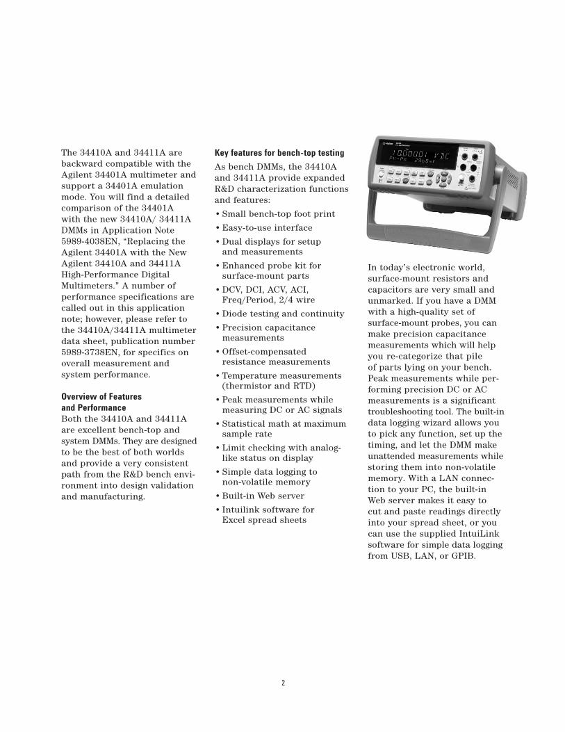
Key features for bench-top testing
As bench DMMs, the 34410A and 34411A provide expanded R&D characterization functionsand features:
• Small bench-top foot print
• Easy-to-use interface
• Dual displays for setup and measurements
• Enhanced probe kit for surface-mount parts
• DCV, DCI, ACV, ACI, Freq/Period, 2/4 wire
• Diode testing and continuity
• Precision capacitance measurements
• Offset-compensated resistance measurements
• Temperature measurements (thermistor and RTD)
• Peak measurements while measuring DC or AC signals
• Statistical math at maximum sample rate
• Limit checking with analog-like status on display
• Simple data logging to non-volatile memory
• Built-in Web server
• Intuilink software for Excel spread sheets
In today’s electronic world,surface-mount resistors andcapacitors are very small andunmarked. If you have a DMMwith a high-quality set of surface-mount probes, you canmake precision capacitancemeasurements which will helpyou re-categorize that pile of parts lying on your bench. Peak measurements while per-forming precision DC or ACmeasurements is a significanttroubleshooting tool. The built-indata logging wizard allows youto pick any function, set up thetiming, and let the DMM makeunattended measurements whilestoring them into non-volatilememory. With a LAN connec-tion to your PC, the built-inWeb server makes it easy to cut and paste readings directlyinto your spread sheet, or youcan use the supplied IntuiLinksoftware for simple data loggingfrom USB, LAN, or GPIB.
2

Key features for system useRemove the rubber bumpersand handle, and you have asystem-ready DMM that canoutperform even VXI and PXIinstrumentation. You get higherthroughput in high-volumemanufacturing for applicationssuch as wireless handsets,wireless LAN, Bluetooth, and automotive testing.
Key features for the system user:
• Front and rear input terminals
• Easy-to-use SCPI command language
• Up to 50 k readings/s, continuous to PC
• Traceable accuracy in additionto fast measurements
• Retrieve readings up to 270,000/s from reading storage
• Sub-millisecond command parsing
• Sub-microsecond external trigger latencies
• Hardware handshake to switch instruments
• Precision sample timer for waveform capture
• Peak measurements while measuring DC or AC signals
• 100-Mbit LAN, USB 2.0, and GPIB
• Web server for remote access
• LXI Class C compliant
• 34401A emulation mode
• Drivers for IVI and LabVIEWTM
These DMMs are system ready –you turn them on, and they’reready for operation from thefront panel or through a Webbrowser. You don’t have toinstall drivers before you can even use the instrument.Having a built-in Web servergives you complete control ofthe DMM from any computerthat has a LAN port. If you canconnect to eBay.com, you canconnect to these DMMs withoutthe need for any driver software.
Developing programs is almostas easy. The DMMs come withAgilent’s powerful VISA I/Olibrary, drivers, and examples forthe most popular programmingdevelopment environments, soyou are programming withinminutes, not hours.
If you are considering replacingthe 34401A in your test system, allyou need to do is put the 34410Aor 34411A in emulation modeusing the “SYSTem:LANGuage34401A” command. You do nothave to rewrite your tests –except to compensate for amuch faster instrument andhigher-resolution measure-ments. This mode is retained in nonvolatile memory, so whenyou cycle power, the DMM still thinks it is a 34401A.Please refer to ApplicationNote 5989-4038EN, “Replacingthe Agilent 34401A with thenew Agilent 34410A and34411A High-PerformanceDigital Multimeters.”
3
Applications and SolutionsWhether your applicationrequires general-purpose measurements, precision DC and AC measurements,waveform capture of mechanical-electrical signals, or fastthroughput and programmingspeed, these new DMMs havethe measurement capabilityyou need. This section givesyou examples that demonstratesome of the newer capabilitiesnot found in many general-purpose DMMs. The next section, “Understanding FastMeasurements,” will show you how to configure yourDMM for these measurements.
Precision measurements with high NMRThe 34410A and 34411A use a special aperture-shapingalgorithm to increase normalmode rejection (NMR) ofpower-line-related noise in DC measurements. It is anincreasing and decreasingseries of weighted averages of multiple measurements. This special algorithm is utilized on NPLC settings of 2, 10, and 100. At 1 PLC, the NMR is specified as 55 dB, but at 2 PLC, the rejectionleaps to 110 dB at ±0.1% of the power line frequency.
Most DMMs provide only 60 dB of rejection at 10 and100 NPLC settings and ±0.1% ofdeviation from line frequency.However, the shaped aperturealgorithm creates a wider notchof operating frequency andachieves 75 dB at ±1% and 55 dBat ±3%. This allows higher-precision measurements atfaster rates than is availablefrom most other DMMs on the market.
Precision capacitance measurementsWhen you are designing circuits,it is highly advantageous toknow the actual value of acapacitor to be used in a circuit.Hand-held multimeters andmost 51/2 digit multimeters typically use a measurementtechnique that assumes an idealcapacitor being charged by anideal constant current sourceto determine capacitance withthe formula C = I/(dV/dt). Theseinstruments then specify anerror of 1% or more for filmcapacitors (polyester andpolypropylene dielectrics) but do not specify errors forcapacitors of other dielectrics.
Real-world capacitors exhibitnon-ideal behavior due todielectric absorption, leakage,dissipation factor, and nonlinearequivalent series resistance(ESR). Current sources are notideal either, so a substantialamount of error can be intro-duced using this time-domain,straight-line approximationtechnique.
The 34410A and 34411A use a patented, time-domainalgorithm to reject some of thenon-ideal performance charac-teristics of capacitors. Firstand foremost, the A-to-D isable to sample fast enough tocapture multiple points on thecharge ramp of the capacitorunder test without introducingsignificant noise to the mea-surement. Second, the constantcurrent source does not havesubstantial non-ideal behaviorssuch as a thermal tail whenturning on. Third, the internal
4
capacitance of the DMM andlead capacitance of the probescan be calibrated out using the built-in math null function,which subtracts the initial mea-surement from all subsequentmeasurements.
Substantial improvements inaccuracy are attained usingthis technique. The 34410Aand 34411A DMMs can actuallyperform much better than their0.5% specifications. In lab testingon a high-accuracy capacitancestandard, these DMMs achieveda performance level on the orderof 0.1%. Furthermore, measure-ments of capacitors with poordielectrics, such as aluminum-electrolytic capacitors, showedgreatly improved accuracy.
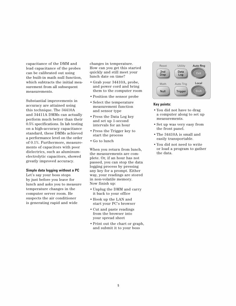
Simple data logging without a PCLet’s say your boss stops by just before you leave forlunch and asks you to measuretemperature changes in thecomputer server room. He suspects the air conditioner is generating rapid and wide
changes in temperature. How can you get this startedquickly and still meet yourlunch date on time?
• Grab your 34410A, probe, and power cord and bring them to the computer room
• Position the sensor probe
• Select the temperature measurement function and sensor type
• Press the Data Log key and set up 1-second intervals for an hour
• Press the Trigger key to start the process
• Go to lunch
When you return from lunch,the measurements are com-plete. Or, if an hour has notpassed, you can stop the datalogging process by pressing any key for a prompt. Eitherway, your readings are storedin non-volatile memory. Now finish up:
• Unplug the DMM and carryit back to your office
• Hook up the LAN and start your PC’s browser
• Cut and paste readings from the browser into your spread sheet
• Print out the chart or graph, and submit it to your boss
Key points:
• You did not have to drag a computer along to set up measurements.
• Set up was very easy from the front panel.
• The 34410A is small and easily transportable.
• You did not need to write or load a program to gather the data.
5
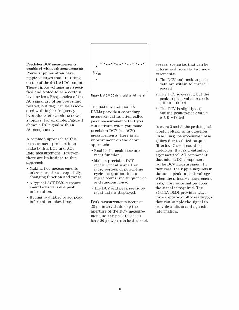
Precision DCV measurementscombined with peak measurementsPower supplies often have ripple voltages that are ridingon top of the desired DC output.These ripple voltages are speci-fied and tested to be a certainlevel or less. Frequencies of theAC signal are often power-linerelated, but they can be associ-ated with higher-frequencybyproducts of switching powersupplies. For example, Figure 1shows a DC signal with an AC component.
A common approach to thismeasurement problem is tomake both a DCV and ACVRMS measurement. However,there are limitations to thisapproach:
• Making two measurementstakes more time – especially changing function and range.
• A typical ACV RMS measure-ment lacks valuable peak information.
• Having to digitize to get peak information takes time.
The 34410A and 34411A DMMs provide a secondarymeasurement function calledpeak measurements that youcan activate when you makeprecision DCV (or ACV) measurements. Here is animprovement on the aboveapproach:
• Enable the peak measure-ment function.
• Make a precision DCV measurement using 1 or more periods of power-line cycle integration time to reject power line frequencies and random noise.
• The DCV and peak measure-ment data is displayed.
Peak measurements occur at20-µs intervals during the aperture of the DCV measure-ment, so any peak that is atleast 20 µs wide can be detected.
Several scenarios that can bedetermined from the two mea-surements:
1. The DCV and peak-to-peak data are within tolerance – passed
2. The DCV is correct, but the peak-to-peak value exceeds a limit – failed
3. The DCV is slightly off, but the peak-to-peak value is OK – failed
In cases 2 and 3, the peak-to-peakripple voltage is in question.Case 2 may be excessive noisespikes due to failed output filtering. Case 3 could be distortion that is creating anasymmetrical AC componentthat adds a DC component to the DCV measurement. Inthat case, the ripple may retainthe same peak-to-peak voltage.When the primary measurementfails, more information aboutthe signal is required. The34411A DMM provides wave-form capture at 50 k readings/sthat can sample the signal toprovide additional diagnosticinformation.
6
Figure 1. A 5 V DC signal with an AC signal
5 VDC
In manufacturing, the goal is to minimize test time, so thecombination of precision DCVand peak measurements cansignificantly reduce test timecompared to making individualDCV and ACV measurementsor digitizing and processing thesignal. The additional benefit is obtaining the peak-to-peakinformation which can betterindicate the quality of thepower supply’s output signal.
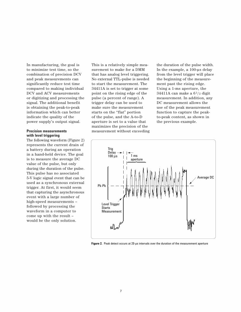
Precision measurements with level triggeringThe following waveform (Figure 2)represents the current drain ofa battery during an operationin a hand-held device. The goalis to measure the average DCvalue of the pulse, but onlyduring the duration of the pulse.This pulse has no associated 5-V logic signal event that can beused as a synchronous externaltrigger. At first, it would seemthat capturing the asynchronousevent with a large number ofhigh-speed measurements – followed by processing thewaveform in a computer tocome up with the result –would be the only solution.
This is a relatively simple mea-surement to make for a DMMthat has analog level triggering.No external TTL-pulse is neededto start the measurement. The34411A is set to trigger at somepoint on the rising edge of thepulse (a percent of range). Atrigger delay can be used tomake sure the measurementstarts on the “flat” portion of the pulse, and the A-to-Daperture is set to a value thatmaximizes the precision of themeasurement without exceeding
the duration of the pulse width.In the example, a 100-µs delayfrom the level trigger will placethe beginning of the measure-ment past the rising edge. Using a 1-ms aperture, the34411A can make a 61/2 digitmeasurement. In addition, anyDC measurement allows theuse of the peak measurementfunction to capture the peak-to-peak content, as shown inthe previous example.
7
TrigDelay100 µs
Pk-Pk
Level TriggerStartsMeasurement
Average DC
1 ms aperture
Figure 2. Peak detect occurs at 20-µs intervals over the duration of the measurement aperture

Testing fluorescent ballasts using direct-sampled ACVWhen a fluorescent lamp is off,the mercury/gas mixture withinthe tube is non-conductive. Whenpower is first applied, 300 VACis needed to initiate a gas dis-charge of mercury radiation.The electric current passingthrough the low-pressure gasemits UV light. The internalphosphor coating efficientlyconverts most of the U V to visible light. Once the initialdischarge takes place, a muchlower voltage – usually a voltage from 100 VAC to 175 VAC – is needed to main-tain the discharge, dependentupon the wattage rating of the bulb.
A DMM is needed to test the ballast voltages to assurethe correct voltages are beingapplied. This is an ACV mea-surement. Many DMMs, includingthe Agilent 34401A, use ananalog RMS converter for ACV measurements. Althoughthese converters can measurefrequency content as high as 1 MHz, they do not do a verygood job of telling the DMMthat short-duration, high-voltage spikes may be presenton the input. These short spikesmay have little impact on RMS content, so the resultingvoltage measurement mayhardly deviate from the expected voltage.
For example, the ballast mayactually generate 1-kV or higher spikes along with the300-VAC signal needed for initial startup. The DMM mayread 300 VAC and occasionally301 VAC. The test system thinksthat is just fine – well withintolerance. However, you do not see the huge voltage spikespounding against the input section of the DMM. If theDMM does not have effectiveinput protection, the input circuitry can eventually failafter continued abuse.
The 34410A and 34411A use a direct sampling technique tomake AC RMS measurements.Relative to analog RMS calcu-lations, the direct sampling technique offers four primaryadvantages: 10-times faster AC measurements, improvedaccuracy for high-frequencysinusoids, peak-to-peak infor-mation, and no crest factor de-rating.
Significant over-sampling ofthe input signal can detect thenarrow, high-voltage spikes,and the DMM can then respondto those spikes with an overloaderror condition. This informsthe test engineer that a problemexists either in the wiring connections to the DMM or inthe ballast. The solution can beas simple as adding filtering inthe fixture to suppress expectedspikes before arriving at theinput terminals of the DMM.Either way, the test engineer is better informed by a DMMthat can “see” that actual contentof the signal. Direct-sampledAC provides that visibility intosignal content, so both RMSand peak measurements can be made simultaneously.
8
Figure 3. Ballast voltage needed to start a fluorescent bulb and then keep it lit
Initial Discharge – 300 VAC Steady State – 100 VAC
Level triggering with scope-like waveform captureAerospace and automotiveapplications are replete withmechanical-electrical signals.There are mechanical partsthat oscillate, vibrate, andexperience tension or compres-sion. The frequency content of these signals is relativelylow, often less than 8 kHz. Forexample, a typical accelerometerwill have a bandwidth of 2.5 kHz.The 34411A provides waveformcapture for these types of signalsusing the following capabilities:
• 50-kHz sample rate at 4.5 digits using a low-jitter sample timer
• Bandwidth response relativelyflat (< 0.1 dB at 3 kHz; < 0.6 dB at 8 kHz)
• Analog level trigger
• Pre- and post-trigger sampling
• 1-million-reading storage
• 270-k readings/s access to reading storage
Electronic signals generated infunctional test applicationsalso are often below 8 kHz:voice signals of 300 Hz to 3 kHz,battery drain in handhelddevices such as cell phones,cameras, or PDAs, and otherlow-frequency-content signals.The measurement of currentdrain in handheld devices iscommonplace in the electronicsindustry. Long battery life is a key factor in customer satis-faction. It is important tounderstand the current drainfor various operations of ahandheld device.
Some Agilent power suppliescan sample accurately atmicroampere levels the currentwaveform supplied to a deviceunder test. The Agilent N6700power supplies provide thiscapability. However, the mea-surement is limited to the cur-rent coming out of the supply.
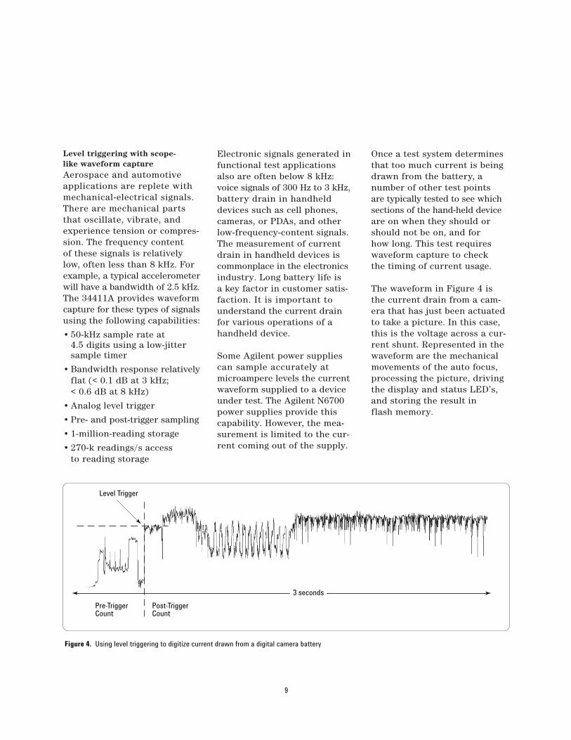
Once a test system determinesthat too much current is beingdrawn from the battery, a number of other test points are typically tested to see whichsections of the hand-held deviceare on when they should orshould not be on, and for how long. This test requireswaveform capture to check the timing of current usage.
The waveform in Figure 4 isthe current drain from a cam-era that has just been actuatedto take a picture. In this case,this is the voltage across a cur-rent shunt. Represented in thewaveform are the mechanicalmovements of the auto focus,processing the picture, drivingthe display and status LED’s,and storing the result in flash memory.
9
Level Trigger
Pre-TriggerCount
Post-TriggerCount
3 seconds
Figure 4. Using level triggering to digitize current drawn from a digital camera battery
The 34411A level trigger isspecified in units of any mea-surement function. In this case,a DCV measurement is beingmade at 50 k samples/s. With 1 million readings, 20 seconds of data can be stored at thisrate. Pre- and post-triggeringallows you to create a scope-like capture of the waveformaround an event. The DMM willcontinuously make measurementsuntil the level trigger is met. Itwill retain the pre-trigger countof measurements and then beginthe count of post-trigger mea-surements. This is an excellentalternative to waiting for anasynchronous event, and thereis no discontinuity of measure-ments between pre- and post-trigger counts.
Delayed sampling from occur-rence of an external triggerIn many applications, you needto wait a period of time beforeactually making a measurement,as illustrated in the examplewhere we discussed precisionDC measurements of pulses.There are many reasons fordelaying a measurement. Youmay need to wait for the signalto settle – as is typical whenyou are measuring large resis-tances in the presence of straycapacitance. In the ballastapplication we discussed earlier,a delay is needed to make theinstrument wait until after theinitial high-voltage dischargehas taken place, so the quies-cent AC voltage level can bemeasured.
Both the 34410A and 34411Ahave a hardware-coupled external trigger input. A delaycan be inserted between theexternal event and the start of any measurement. Thisdelay can be zero, and the measurement engine starts itsmeasurement in less than 1 µsfrom the external trigger (DCmeasurement). The delay canalso be up to 3600 seconds(with 20 µs resolution).
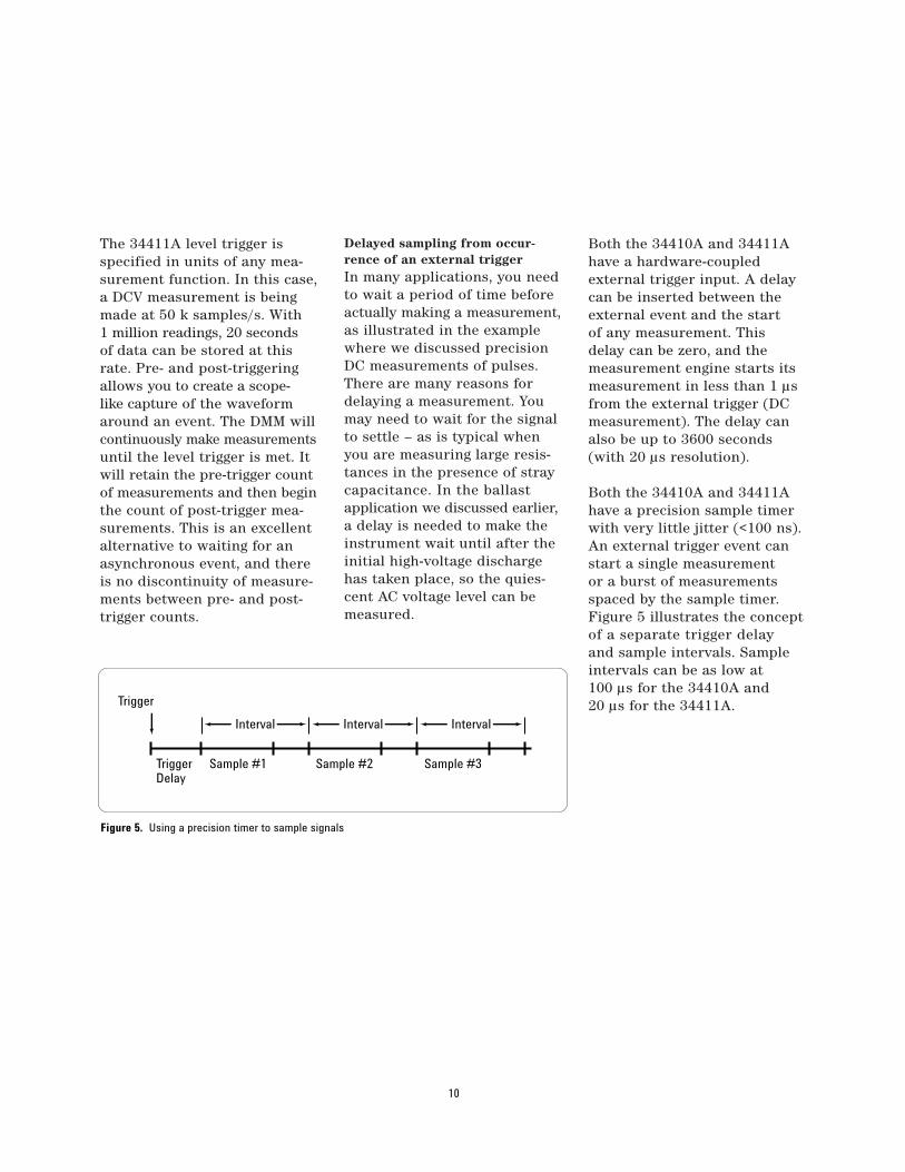
Both the 34410A and 34411Ahave a precision sample timerwith very little jitter (<100 ns).An external trigger event canstart a single measurement or a burst of measurementsspaced by the sample timer.Figure 5 illustrates the conceptof a separate trigger delay and sample intervals. Sampleintervals can be as low at 100 µs for the 34410A and 20 µs for the 34411A.
10
Interval Interval Interval
Trigger
TriggerDelay
Sample #1 Sample #2 Sample #3
Figure 5. Using a precision timer to sample signals
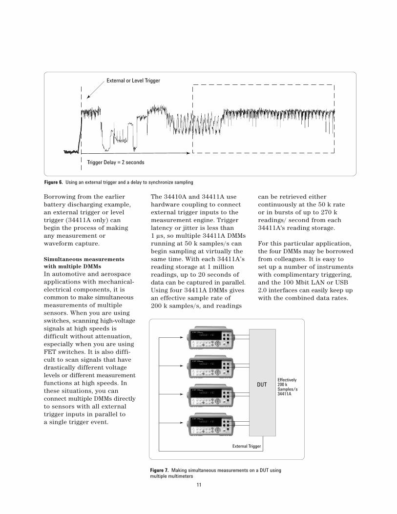
Borrowing from the earlier battery discharging example,an external trigger or level trigger (34411A only) can begin the process of makingany measurement or waveform capture.
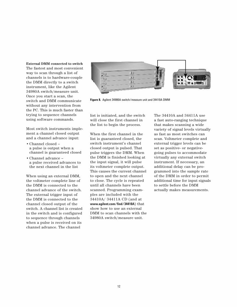
Simultaneous measurements with multiple DMMsIn automotive and aerospaceapplications with mechanical-electrical components, it iscommon to make simultaneousmeasurements of multiple sensors. When you are usingswitches, scanning high-voltagesignals at high speeds is difficult without attenuation,especially when you are usingFET switches. It is also diffi-cult to scan signals that havedrastically different voltage levels or different measurementfunctions at high speeds. Inthese situations, you can connect multiple DMMs directlyto sensors with all externaltrigger inputs in parallel to a single trigger event.
The 34410A and 34411A usehardware coupling to connectexternal trigger inputs to themeasurement engine. Triggerlatency or jitter is less than 1 µs, so multiple 34411A DMMsrunning at 50 k samples/s canbegin sampling at virtually thesame time. With each 34411A’sreading storage at 1 millionreadings, up to 20 seconds ofdata can be captured in parallel.Using four 34411A DMMs givesan effective sample rate of 200 k samples/s, and readings
can be retrieved either continuously at the 50 k rate or in bursts of up to 270 kreadings/ second from each34411A's reading storage.
For this particular application,the four DMMs may be borrowedfrom colleagues. It is easy toset up a number of instrumentswith complimentary triggering,and the 100 Mbit LAN or USB2.0 interfaces can easily keep upwith the combined data rates.
11
External or Level Trigger
Trigger Delay = 2 seconds
External Trigger
Effectively200 kSamples/s34411A
DUT
Figure 6. Using an external trigger and a delay to synchronize sampling
Figure 7. Making simultaneous measurements on a DUT using multiple multimeters
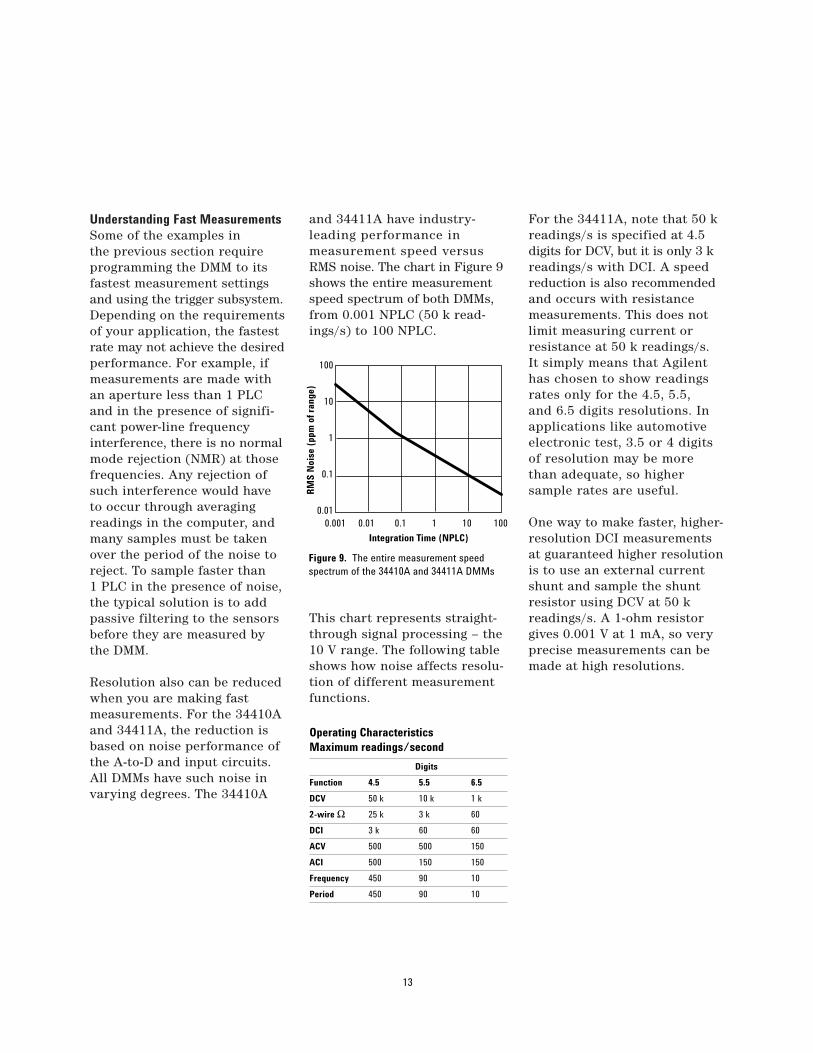
External DMM connected to switchThe fastest and most convenientway to scan through a list ofchannels is to hardware-couplethe DMM directly to a switchinstrument, like the Agilent34980A switch/measure unit.Once you start a scan, theswitch and DMM communicatewithout any intervention fromthe PC. This is much faster thantrying to sequence channelsusing software commands.
Most switch instruments imple-ment a channel closed outputand a channel advance input:
• Channel closed – a pulse is output when a channel is guaranteed closed
• Channel advance – a pulse received advances to the next channel in the list
When using an external DMM,the voltmeter complete line ofthe DMM is connected to thechannel advance of the switch.The external trigger input ofthe DMM is connected to thechannel closed output of theswitch. A channel list is createdin the switch and is configuredto sequence through channelswhen a pulse is received on itschannel advance. The channel
list is initiated, and the switchwill close the first channel inthe list to begin the process.
When the first channel in thelist is guaranteed closed, theswitch instrument’s channelclosed output is pulsed. Thatpulse triggers the DMM. Whenthe DMM is finished looking atthe input signal, it will pulseits voltmeter complete output.This causes the current channelto open and the next channelto close. The cycle is repeateduntil all channels have beenscanned. Programming exam-ples are included with the34410A/ 34411A CD (and atwww.agilent.com/find/34410A) thatshow how to use an externalDMM to scan channels with the34980A switch/measure unit.
The 34410A and 34411A use a fast auto-ranging techniquethat makes scanning a widevariety of signal levels virtuallyas fast as most switches canscan. Voltmeter complete andexternal trigger levels can beset as positive- or negative-going pulses to accommodatevirtually any external switchinstrument. If necessary, anadditional delay can be pro-grammed into the sample rateof the DMM in order to permitadditional time for input signalsto settle before the DMM actually makes measurements.
12
Figure 8. Agilent 34980A switch/measure unit and 34410A DMM
Understanding Fast MeasurementsSome of the examples in the previous section requireprogramming the DMM to itsfastest measurement settingsand using the trigger subsystem.Depending on the requirementsof your application, the fastestrate may not achieve the desiredperformance. For example, ifmeasurements are made withan aperture less than 1 PLCand in the presence of signifi-cant power-line frequencyinterference, there is no normalmode rejection (NMR) at thosefrequencies. Any rejection ofsuch interference would haveto occur through averagingreadings in the computer, andmany samples must be takenover the period of the noise toreject. To sample faster than 1 PLC in the presence of noise,the typical solution is to addpassive filtering to the sensorsbefore they are measured bythe DMM.
Resolution also can be reducedwhen you are making fast measurements. For the 34410Aand 34411A, the reduction isbased on noise performance ofthe A-to-D and input circuits.All DMMs have such noise invarying degrees. The 34410A
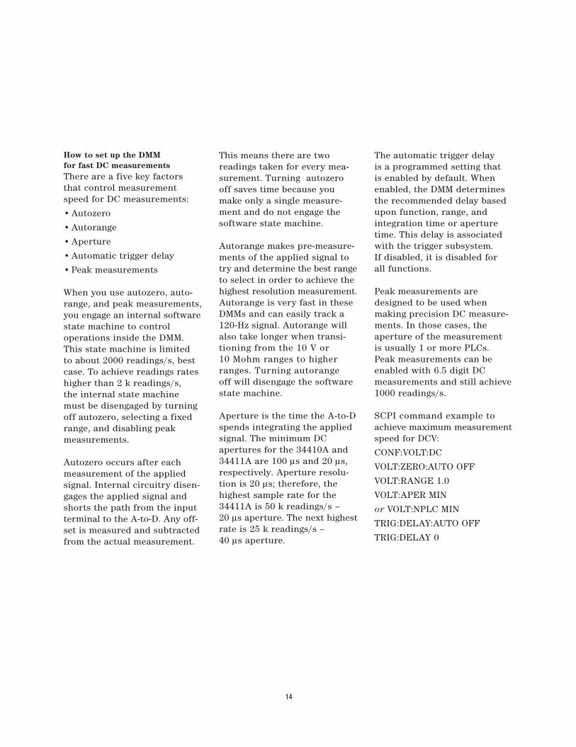
and 34411A have industry-leading performance in measurement speed versusRMS noise. The chart in Figure 9shows the entire measurementspeed spectrum of both DMMs,from 0.001 NPLC (50 k read-ings/s) to 100 NPLC.
This chart represents straight-through signal processing – the10 V range. The following tableshows how noise affects resolu-tion of different measurementfunctions.
For the 34411A, note that 50 kreadings/s is specified at 4.5digits for DCV, but it is only 3 kreadings/s with DCI. A speedreduction is also recommendedand occurs with resistancemeasurements. This does notlimit measuring current orresistance at 50 k readings/s. It simply means that Agilenthas chosen to show readingsrates only for the 4.5, 5.5, and 6.5 digits resolutions. Inapplications like automotiveelectronic test, 3.5 or 4 digitsof resolution may be more than adequate, so higher sample rates are useful.
One way to make faster, higher-resolution DCI measurementsat guaranteed higher resolutionis to use an external currentshunt and sample the shuntresistor using DCV at 50 kreadings/s. A 1-ohm resistorgives 0.001 V at 1 mA, so veryprecise measurements can bemade at high resolutions.
13
100
10
1
0.1
0.010.001 0.01 0.1 1 10 100
RM
S N
oise
(pp
m o
f ran
ge)
Integration Time (NPLC)
Operating Characteristics Maximum readings/second
Digits
Function 4.5 5.5 6.5
DCV 50 k 10 k 1 k
2-wire Ω 25 k 3 k 60
DCI 3 k 60 60
ACV 500 500 150
ACI 500 150 150
Frequency 450 90 10
Period 450 90 10
Figure 9. The entire measurement speed spectrum of the 34410A and 34411A DMMs
How to set up the DMM for fast DC measurementsThere are a five key factorsthat control measurementspeed for DC measurements:
• Autozero
• Autorange
• Aperture
• Automatic trigger delay
• Peak measurements
When you use autozero, auto-range, and peak measurements,you engage an internal softwarestate machine to control operations inside the DMM.This state machine is limited to about 2000 readings/s, bestcase. To achieve readings rateshigher than 2 k readings/s, the internal state machinemust be disengaged by turningoff autozero, selecting a fixedrange, and disabling peak measurements.
Autozero occurs after eachmeasurement of the appliedsignal. Internal circuitry disen-gages the applied signal andshorts the path from the inputterminal to the A-to-D. Any off-set is measured and subtractedfrom the actual measurement.
This means there are two readings taken for every mea-surement. Turning autozerooff saves time because youmake only a single measure-ment and do not engage thesoftware state machine.
Autorange makes pre-measure-ments of the applied signal totry and determine the best rangeto select in order to achieve thehighest resolution measurement.Autorange is very fast in theseDMMs and can easily track a120-Hz signal. Autorange willalso take longer when transi-tioning from the 10 V or 10 Mohm ranges to higherranges. Turning autorange off will disengage the softwarestate machine.
Aperture is the time the A-to-Dspends integrating the appliedsignal. The minimum DC apertures for the 34410A and34411A are 100 µs and 20 µs,respectively. Aperture resolu-tion is 20 µs; therefore, thehighest sample rate for the34411A is 50 k readings/s – 20 µs aperture. The next highestrate is 25 k readings/s – 40 µs aperture.
The automatic trigger delay is a programmed setting that is enabled by default. Whenenabled, the DMM determinesthe recommended delay basedupon function, range, and integration time or aperturetime. This delay is associatedwith the trigger subsystem. If disabled, it is disabled for all functions.
Peak measurements aredesigned to be used when making precision DC measure-ments. In those cases, the aperture of the measurement is usually 1 or more PLCs. Peak measurements can beenabled with 6.5 digit DC measurements and still achieve1000 readings/s.
SCPI command example toachieve maximum measurementspeed for DCV:
CONF:VOLT:DC
VOLT:ZERO:AUTO OFF
VOLT:RANGE 1.0
VOLT:APER MIN
or VOLT:NPLC MIN
TRIG:DELAY:AUTO OFF
TRIG:DELAY 0
14
The aperture setting is set toMIN. For the 34410A, thiswould be 100 µs. For the34411A, 20 µs is the MIN. Thesame commands can be usedfor DCI, ohms, or temperature– but you have to change theVOLT to CURR, RES, FRES, or TEMP.
Autozero cannot be turned offwhen making four-wire ohmsmeasurements. Temperaturemeasurements are all resistiveand can be two- or four-wiremeasurements.
How to set up the DMM for fast AC measurementsFor AC measurements, the following are the key factors in measurement speed:
• AC filter setting
• Autorange
• Automatic trigger delay
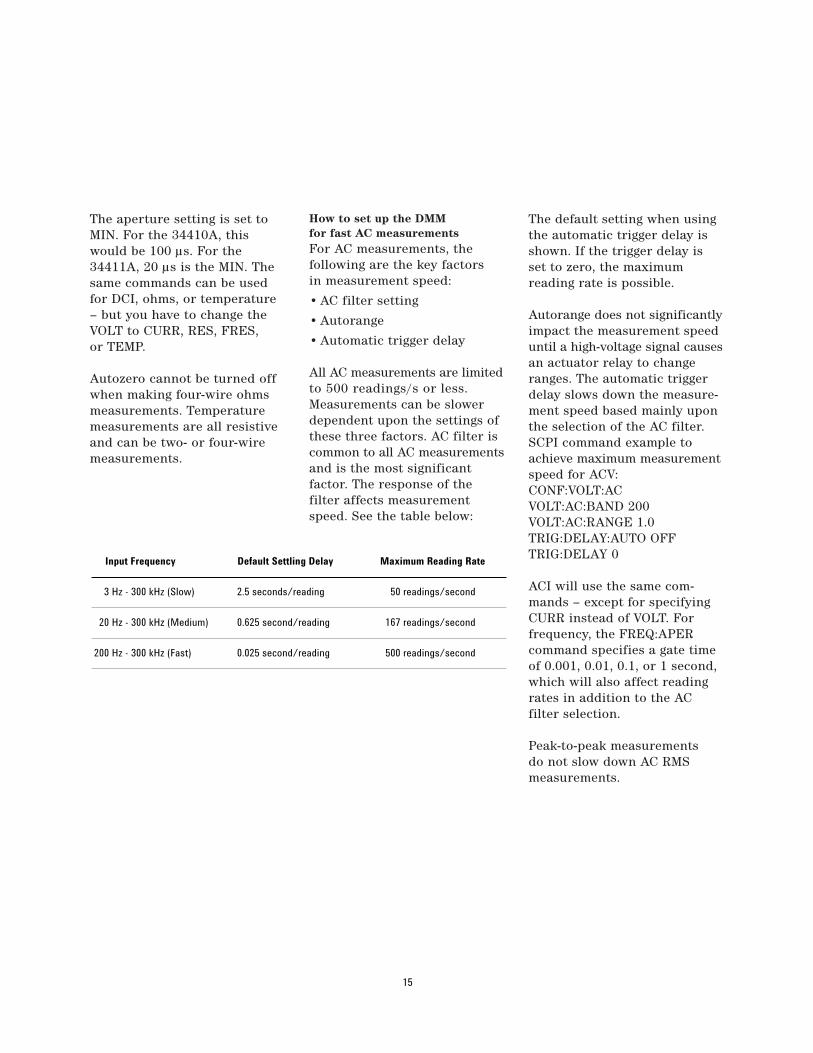
All AC measurements are limitedto 500 readings/s or less.Measurements can be slowerdependent upon the settings ofthese three factors. AC filter iscommon to all AC measurementsand is the most significant factor. The response of the filter affects measurementspeed. See the table below:
The default setting when usingthe automatic trigger delay isshown. If the trigger delay isset to zero, the maximum reading rate is possible.
Autorange does not significantlyimpact the measurement speeduntil a high-voltage signal causesan actuator relay to changeranges. The automatic triggerdelay slows down the measure-ment speed based mainly uponthe selection of the AC filter.SCPI command example toachieve maximum measurementspeed for ACV:CONF:VOLT:ACVOLT:AC:BAND 200VOLT:AC:RANGE 1.0TRIG:DELAY:AUTO OFFTRIG:DELAY 0
ACI will use the same com-mands – except for specifyingCURR instead of VOLT. For frequency, the FREQ:APERcommand specifies a gate timeof 0.001, 0.01, 0.1, or 1 second,which will also affect readingrates in addition to the AC filter selection.
Peak-to-peak measurements do not slow down AC RMS measurements.
15
Input Frequency Default Settling Delay Maximum Reading Rate
3 Hz - 300 kHz (Slow) 2.5 seconds/reading 50 readings/second
20 Hz - 300 kHz (Medium) 0.625 second/reading 167 readings/second
200 Hz - 300 kHz (Fast) 0.025 second/reading 500 readings/second
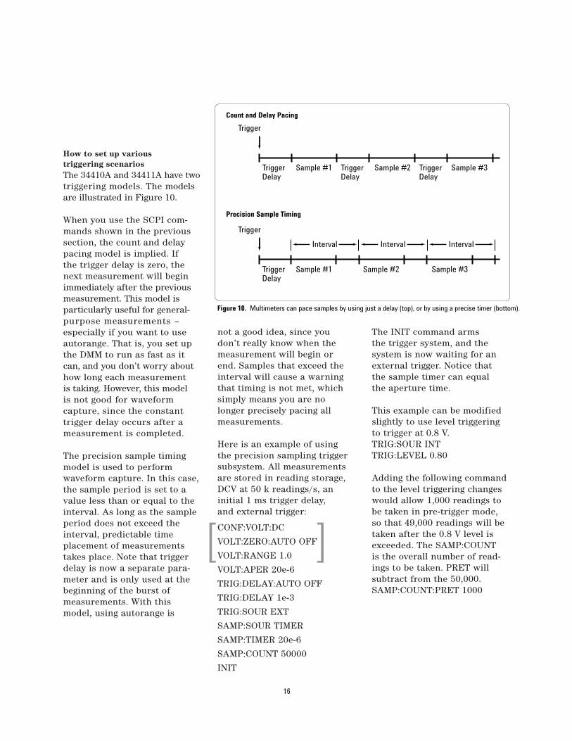
How to set up various triggering scenariosThe 34410A and 34411A have twotriggering models. The modelsare illustrated in Figure 10.
When you use the SCPI com-mands shown in the previoussection, the count and delaypacing model is implied. If the trigger delay is zero, thenext measurement will beginimmediately after the previousmeasurement. This model is particularly useful for general-purpose measurements – especially if you want to useautorange. That is, you set upthe DMM to run as fast as itcan, and you don’t worry abouthow long each measurement is taking. However, this model is not good for waveform capture, since the constanttrigger delay occurs after ameasurement is completed.
The precision sample timingmodel is used to perform waveform capture. In this case,the sample period is set to avalue less than or equal to theinterval. As long as the sampleperiod does not exceed theinterval, predictable timeplacement of measurementstakes place. Note that triggerdelay is now a separate para-meter and is only used at thebeginning of the burst of measurements. With thismodel, using autorange is
not a good idea, since youdon’t really know when themeasurement will begin or end. Samples that exceed theinterval will cause a warningthat timing is not met, whichsimply means you are nolonger precisely pacing all measurements.
Here is an example of using the precision sampling triggersubsystem. All measurementsare stored in reading storage,DCV at 50 k readings/s, an initial 1 ms trigger delay, and external trigger:
CONF:VOLT:DC
VOLT:ZERO:AUTO OFF
VOLT:RANGE 1.0
VOLT:APER 20e-6
TRIG:DELAY:AUTO OFF
TRIG:DELAY 1e-3
TRIG:SOUR EXT
SAMP:SOUR TIMER
SAMP:TIMER 20e-6
SAMP:COUNT 50000
INIT
The INIT command arms the trigger system, and the system is now waiting for anexternal trigger. Notice that the sample timer can equal the aperture time.
This example can be modifiedslightly to use level triggeringto trigger at 0.8 V.TRIG:SOUR INTTRIG:LEVEL 0.80
Adding the following commandto the level triggering changeswould allow 1,000 readings tobe taken in pre-trigger mode,so that 49,000 readings will betaken after the 0.8 V level isexceeded. The SAMP:COUNT is the overall number of read-ings to be taken. PRET willsubtract from the 50,000.SAMP:COUNT:PRET 1000
16
Trigger
TriggerDelay
TriggerDelay
TriggerDelay
Sample #1 Sample #2 Sample #3
Interval Interval Interval
Trigger
TriggerDelay
Sample #1 Sample #2 Sample #3
Count and Delay Pacing
Precision Sample Timing
Figure 10. Multimeters can pace samples by using just a delay (top), or by using a precise timer (bottom).
[ ]
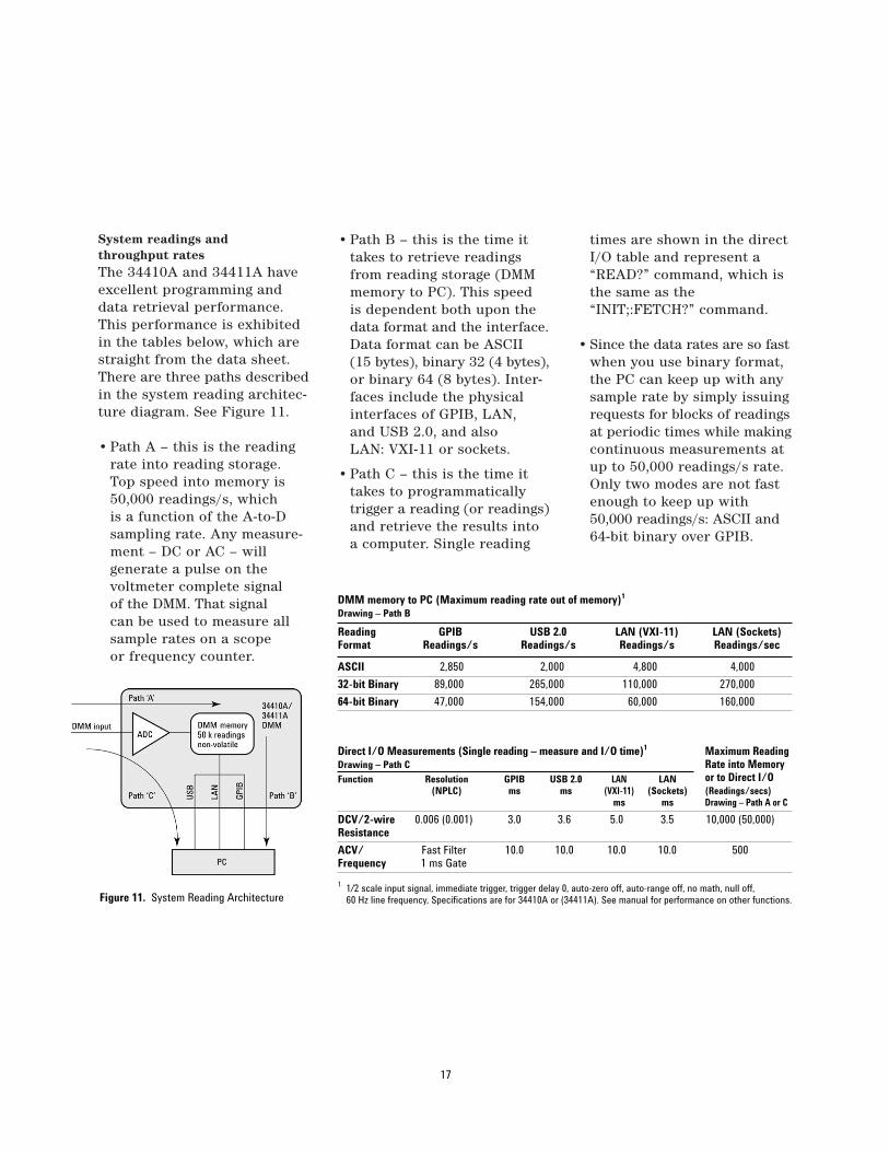
System readings and throughput ratesThe 34410A and 34411A haveexcellent programming anddata retrieval performance.This performance is exhibitedin the tables below, which arestraight from the data sheet.There are three paths describedin the system reading architec-ture diagram. See Figure 11.
• Path A – this is the readingrate into reading storage. Top speed into memory is50,000 readings/s, which is a function of the A-to-Dsampling rate. Any measure-ment – DC or AC – will generate a pulse on the voltmeter complete signal of the DMM. That signalcan be used to measure allsample rates on a scope or frequency counter.
• Path B – this is the time ittakes to retrieve readingsfrom reading storage (DMMmemory to PC). This speed is dependent both upon thedata format and the interface.Data format can be ASCII (15 bytes), binary 32 (4 bytes),or binary 64 (8 bytes). Inter-faces include the physicalinterfaces of GPIB, LAN, and USB 2.0, and also LAN: VXI-11 or sockets.
• Path C – this is the time ittakes to programmaticallytrigger a reading (or readings)and retrieve the results into a computer. Single reading
times are shown in the directI/O table and represent a“READ?” command, which isthe same as the“INIT;:FETCH?” command.
• Since the data rates are so fastwhen you use binary format,the PC can keep up with anysample rate by simply issuingrequests for blocks of readingsat periodic times while makingcontinuous measurements atup to 50,000 readings/s rate.Only two modes are not fastenough to keep up with50,000 readings/s: ASCII and64-bit binary over GPIB.
17
DMM memory to PC (Maximum reading rate out of memory)1
Drawing – Path B
Reading GPIB USB 2.0 LAN (VXI-11) LAN (Sockets)Format Readings/s Readings/s Readings/s Readings/sec
ASCII 2,850 2,000 4,800 4,000
32-bit Binary 89,000 265,000 110,000 270,000
64-bit Binary 47,000 154,000 60,000 160,000
Direct I/O Measurements (Single reading – measure and I/O time)1 Maximum Reading Drawing – Path C Rate into MemoryFunction Resolution GPIB USB 2.0 LAN LAN or to Direct I/O
(NPLC) ms ms (VXI-11) (Sockets) (Readings/secs)ms ms Drawing – Path A or C
DCV/2-wire 0.006 (0.001) 3.0 3.6 5.0 3.5 10,000 (50,000)Resistance
ACV/ Fast Filter 10.0 10.0 10.0 10.0 500Frequency 1 ms Gate
1 1/2 scale input signal, immediate trigger, trigger delay 0, auto-zero off, auto-range off, no math, null off, 60 Hz line frequency, Specifications are for 34410A or (34411A). See manual for performance on other functions.Figure 11. System Reading Architecture

The Advantages of a Built-In Web ServerThe 34410A and 34411A have abuilt-in Web server that providesa very powerful configuration,diagnosis, and programmingtool. All you need is a LANconnection, Web browser, andthe DMM’s IP address. If yourcomputer can access eBay.com,you can access a 34410A/11Afrom anywhere. You need noother software to completelyconfigure the DMM. The DMMcan be configured for DHCP(obtain an IP address from aexternal host), AutoIP (DMMcan assign its own IP address),or manual IP assignment. Onceyou know the IP address, yousimply enter that into the Webbrowser’s URL. Up to three Webbrowsers can be simultaneouslyconnected.
Here are some of the key capabilities provided in the34410A/34411A Web server:
• Extends ease of use by showing all parameters at once
• Visual aid in developing external programs
• Cut and paste readings into your applications
• Log/capture SCPI commands from any interface
• Learning tool to understand how to program the DMM
• Remote/passive monitoring of test system measurements
One of the most powerful capabilities of the Web server –aside from an even easier-to-use-interface and passive monitoring while in a test system – is the SCPI commandlogging feature. You literallydon’t need a manual to learnhow to program the DMM.Using the command loggingcapability of the Web server,
every configuration you makefrom the browser will create an associated SCPI commandsequence that shows how toconfigure the DMM program-matically. You simply cut andpaste the SCPI commands fromthe browser window into yourprogram. This capability isfound under DMM Overviewand the Read/ Clear RemoteI/O Traffic Log selection.
18
ConclusionThe 34410A and 34411A DMMsoffer superior ease of use on thebench, and they offer blisteringperformance for test-systemapplications. Whether yourapplication requires general-purpose measurements, preci-sion DC and AC measurements,waveform capture of mechanical-electrical signals, or fastthroughput and programmingspeed, the 34410A and 34411Aoffer measurement capabilitiesthat make them ideal tools fora broad range of applications.
Glossary
SCPIStandard commands for pro-grammable instrumentation.This is an English-style language that has been used in instrumentation for many years.
IVIInterchangeable virtual instrument. Oriented towardshaving programming routinesthat can be used for any vendor’s DMM.
NMRNormal mode rejection. Usually related to rejectingpower-line frequency noise.
NPLCNumber of power-line cycles.Power line is usually 50 Hz or60 Hz, but it can be 400 Hz.
Related Agilent literature
Data sheets
5989-3738ENAgilent 34410A/34411A 6-1/2 Digit Multimeters
Application notes
5989-4038ENReplacing the Agilent 34401Awith the New Agilent 34410Aand 34411A High-PerformanceDigital Multimeters
You can get copies of these publications at www.agilent.com/find/34410a
19
www.agilent.com
For more information on AgilentTechnologies’ products, applicationsor services, please contact your localAgilent office. The complete list isavailable at:
www.agilent.com/find/contactus
Phone or Fax
United States:(tel) 800 829 4444(fax) 800 829 4433
Canada:(tel) 877 894 4414(fax) 800 746 4866
China:(tel) 800 810 0189(fax) 800 820 2816
Europe:(tel) 31 20 547 2111
Japan:(tel) (81) 426 56 7832(fax) (81) 426 56 7840
Korea:(tel) (080) 769 0800(fax) (080) 769 0900
Latin America:(tel) (305) 269 7500
Taiwan:(tel) 0800 047 866(fax) 0800 286 331
Other Asia Pacific Countries:(tel) (65) 6375 8100(fax) (65) 6755 0042Email: [email protected] revised: 09/26/05
Product specifications and descriptions in this document subject to change without notice.
© Agilent Technologies, Inc. 2006 Printed in the USA August 2, 2006 5989-4039EN
Agilent Technologies’ Test and MeasurementSupport, Services, and AssistanceAgilent Technologies aims to maximize the value you receive, while minimizing your risk and problems. We strive to ensure that you get the test and measurement capabil-ities you paid for and obtain the support you need. Our extensive support resourcesand services can help you choose the rightAgilent products for your applications andapply them successfully. Every instrument and system we sell has a global warranty. Two concepts underlie Agilent’s overall support policy: “Our Promise” and “YourAdvantage.”
Our PromiseOur Promise means your Agilent test andmeasurement equipment will meet itsadvertised performance and functionality.When you are choosing new equipment,we will help you with product information,including realistic performance specifica-tions and practical recommendations fromexperienced test engineers. When youreceive your new Agilent equipment, wecan help verify that it works properly andhelp with initial product operation.
Your AdvantageYour Advantage means that Agilent offers a wide range of additional expert test andmeasurement services, which you can purchase according to your unique technicaland business needs. Solve problems efficiently and gain a competitive edge by contracting with us for calibration, extra-cost upgrades, out-of-warranty repairs, and on-site education and training, as well as design, system integration, project management, and other professionalengineering services. Experienced Agilent engi-neers and technicians worldwide can help youmaximize your productivity, optimize the returnon investment of your Agilent instruments andsystems, and obtain dependable measurementaccuracy for the life of those products.
Agilent Email Updates
www.agilent.com/find/emailupdatesGet the latest information on the products andapplications you select.
Agilent Direct
www.agilent.com/find/agilentdirectQuickly choose and use your test equipmentsolutions with confidence.
Agilent Open
Agilent Open ConnectivityAgilent Open is a versatile combination of test-system hardware, I/O and software tools. Itaccelerates the creation of streamlined test systems that are easy to enhance and maintainby giving you greater choice in measurements,connectivity and programming. Utilizing theseadvantages, your team has more time to focuson what matters most—the performance, reliability and delivery of your product. www.agilent.com/find/open
Agilent Technologies