agreement no.----------/ upneda/solar roof top …...design, supply, installation &...
TRANSCRIPT

Agreement No.----------/ UPNEDA/Solar Roof Top Power Plant/2018
This agreement made on -----------th
day of ---------2018 between Uttar
Pradesh New and Renewable Energy Development Agency, Vibhuti Khand,
Gomti Nagar, Lucknow herein after called UPNEDA on the one part and M/s------
------------------- hereinafter referred to as the Contractor on the other part.
Whereas the UPNEDA decided to enter with firm for the rate contract for
Design, Supply, installation & commissioning and 5 years comprehensive
warranty maintenance of Complete Solar Roof Top Power Plant under CAPEX
MODE at beneficiaries sites in the state of Uttar Pradesh, as decided and desired
by UPNEDA/beneficiaries, on turnkey basis and as the terms and conditions
specified as General conditions of the contract at Annexure-A having 07 pages,
as per Scope of work and technical specifications at Annexure-B having 17 pages,
Warrantee & Maintenance at annexure-C having 01 page and format of Handing
over certificate at Annexure–D having 02 pages, which have been signed by both
the parties and which shall form part of this agreement. The bid document having
65 pages will be treated as the part of this agreement. The agreement shall be valid
for 12 months from the date of signing for purposes of work order and till 5 years
of warranty period from the date of last installation of system for work and
warranty performance.
And whereas the Contractor M/s------------------------- has accepted to Design,
Supply, installation & commissioning and 5 years comprehensive warranty
maintenance of Complete Solar Roof Top Power Plant at the identified sites by
UPNEDA/beneficiaries in the state of Uttar Pradesh.
Now therefore, these present witness and parties aforementioned here by
agree and declare that in consideration of the payment of MNRE & State subsidy
to be made to the beneficiaries by the UPNEDA, the Contractor shall complete the
said work on the terms and conditions mentioned in the contract. For the work
awarded by UPNEDA the payment shall be made to firm as per terms and
conditions mentioned in the general conditions of contract. The rate for UPNEDA
work order and calculating the subsidy is enclosed at annexure-E having page-1
IN WITNESS HERE PARTIES HAVE SIGNED DEED HEREUNDER
Signed ...................................... Signed ......................................
For & on behalf of UPNEDA For & on behalf of Contractor
Witness. Witness.
1. 1.
2. 2.
GENERAL CONDITIONS OF CONTRACT
1. DEFINITIONS
1.2. “UPNEDA’ shall mean The Director of UPNEDA or his representative and shall also include its
successors in interest and assignees. The “Contractor” shall mean (successful bidder) i.e. the person
whose e-tender has been accepted by UPNEDA and shall include his legal representatives and
successors in interest.
1.3 The agreement shall be rate contract on basis valid for 12 month. The work shall be completed
within 3 months from the date of placement of work order by UPNEDA/ Beneficiaries. However for the
work awarded by UPNEDA, “UPNEDA” may in case of urgency ask the bidder to complete the work
earlier, with the mutual consent of the contractor/ bidder. In case the contractor/ bidder fails to execute
the said work within stipulated time, “UPNEDA” will be at liberty to get the work executed from the
other bidder/open market without calling any tender/e-tender and without any notice to the contractor/
bidder, at the risk and cost of the contractor/ bidder. Any additional cost incurred by “UPNEDA” shall
be recovered from the contractor/ bidder. If the cost of executing the work as aforesaid shall exceed the
balance due to the contractor/ bidder, and the contractor/ bidder fails to make good the additional cost,
“UPNEDA” may recover it from the contractor/ bidders’ pending claims against any work in
“UPNEDA” or in any lawful manner.
1.4 That on the request of the contractor/ bidder and also in the interest of the organization the
“UPNEDA” is authorized to extend the validity of the agreement, subject to that the request of the
contractor/ bidder is received before the expiry of the agreement period, or any extended period granted
to the contractor/ bidder. Maximum period of extension shall be 2months on the same terms and
conditions as contained in this agreement.
1.5 The agreement shall be deemed to be extended till the date of completion of last work order
including 5 years comprehensive O&M subject to the completion period as provided in the clause 1.3.
1.6 IN the interest of the work and the programme, agreement executed between the contractor/bidder
and the “UPNEDA” may be extended to a mutually agreed period, if the need so arises. It shall be sole
responsibility of the contractor/ bidder to get verified the quality & quantity of the supplied material at
the site of delivery.
2 LIQUIDATED DAMAGES ( For work order placed by UPNEDA)
2.1 If the contractor/ bidder fails to perform the services within the time periods specified in the
contract (In case of delay for any reason other than due to Force Majeure conditions or any extension
thereof granted to him by UPNEDA) the “UPNEDA” shall without prejudice to its other remedies under
the contract deduct from the contract price as liquidated damage, a sum equivalent to 1.0% of the price
of the unperformed services for each week (For the purposes as calculation of delay, part of week shall
be treated as week) of delay until actual performance up to a maximum deduction of 10% of the delayed
services. Once the maximum is reached, UPNEDA may asses the progress of work and take decision
where the work order is to be cancelled, forfeit the performance security and debar/blacklist the firm or
to continue with time extension with further penalty. The “UPNEDA” may consider termination of the
contract. In the case of violation of contract, UPNEDA may confiscate pending payments/ dues of the

contractor/ bidder assigning specific reasons and shall also have the power to debar/ blacklist the
contractor/bidder in similar circumstances. UPNEDA may also invoke performance/ security bank
guarantee of 10%.
3 The contractor/ bidder shall have to comply with all the rules, regulations, laws and by-
laws for the time being in force and the instructions if any, of the organization, in whose
premises the work has to be done. “UPNEDA” shall have no liability in this regard.
4 FORCE MAJEURE
4.1 Notwithstanding the provisions of clauses contained in this deed; the contractor/ bidder shall not
be liable for forfeiture of its performance security, liquidated damages, termination for default, if he is
unable to fulfill his obligation under this deed due to event of force majeure circumstances.
4.2 For purpose of this clause, "Force majeure" means an event beyond the control of the contractor/
bidder and not involving the contractor/ bidder's fault or negligence and not foreseeable. Such events
may include, but are not restricted to, acts of Government either n its sovereign or contractual capacity,
wars or revolutions, fires, floods, epidemics, quarantine restrictions and fright embargoes
4.3 However, If a force majeure situation arises, the contractor/ bidder shall immediately notify the
“UPNEDA” in writing. The decision of the competent authority of UPNEDA in above conditions shall
be final.
5 The High court of Judicature at Allahabad and Courts subordinate thereto, at Lucknow,
shall alone have jurisdictions to the exclusion of all other courts.
6 The contractor/ bidder shall not, without the consent in writing of “UPNEDA”, transfer,
assign or sublet the work under the contract or any substantial part thereof to any other
party.
7 “UPNEDA” shall have at all reasonable time access to the works being carried out by the
contractor/ bidder under the contract. All the work shall be carried out by the
contractor/bidder to the satisfaction of “UPNEDA”.
8 If any question, dispute or difference what so ever shall arises between “UPNEDA” and
the contractor/ bidder, in the connection with the agreement except as to matters, the
decisions for which have been specifically provided, either party may forthwith give to
the other notice in writing of existence of such question, dispute or difference and the
same shall be referred to the sole arbitration of the Principal Secretary/Secretary of the
Uttar Pradesh or a person nominated by him not below the rank of Secretary. This
reference shall be governed by the Indian Arbitration and Conciliation Act 1996, and the
rules made there under. The award in such arbitration shall be final and binding on both
the parties. Work under the agreement shall be continuing during the arbitration
proceedings unless the “UPNEDA” or the arbitrator directs otherwise
9 (For work order placed by UPNEDA)
“UPNEDA” may at any time by notice in writing to the contractor/ bidder either stops the work
all together or reduces or cut it down. If the work is stopped all together, the contractor/bidder
will only be paid for work done and expenses distinctly incurred by him as on preparation or the
execution of the work up to the date on which such notice is received by him. Such expenses

shall be assessed by “UPNEDA”, whose decision shall be final and bidding on the contractor/
bidder. If the work is cut down the contractor/ bidder will not be paid any compensation what so
ever for the loss or profit which he might have made if he had been allowed to complete all the
work included in the contract.
10 INSPECTION AND TESTS (For work order placed by UPNEDA)
10.1 The following inspection procedures and tests are required by the “UPNEDA” in the presence
of “UPNEDA”’s representative if so desired by “UPNEDA”.
10.2 The “UPNEDA” or its representative shall have the right to inspect and / or to test the goods to
confirm their conformity to the contract. The special conditions of contract and/ or the Technical
specifications shall specify what inspections and test the “UPNEDA” required.
10.3 INSPECTION AT WORKS (For work order placed by UPNEDA)
10.3.1 The “UPNEDA”, his duly authorized representative shall have at all reasonable times access to
the contractor/bidders premises or works and shall have the power at all reasonable time to inspect and
examine the materials and workmanship of the works during its manufacture.
10.3.2 The contractor/ bidder shall give the “UPNEDA”, 15 day's written notice of any material being
ready for testing. It shall be mandatory that such notice should reach “UPNEDA” within 30 days of
placement of work order. Such tests shall be on the contractor/ bidder's accounts/expenses except for the
expenses of the inspector. “UPNEDA” reserves the full rights, to waive off inspection of material.
10.3.3 The contractor/ bidder are required to get the entire lot of the ordered material inspected atone
time, before the supply of the materials. In case the contractor/ bidder fails to get the entire lot inspected
at one time, the total expenses of the further inspection will be borne by the supplier/contractor/ bidder.
10.3.4 UPNEDA will bear the inspector cost at only one manufacturing plant. If a component is
produced in more than one location, then the cost of positioning the inspection in the second and
subsequent plants would be borne by the successful Bidder at their cost.
10.3.5 The inspection by “UPNEDA” and issue of dispatch instruction there on shall in no way limit
the liabilities and responsibilities of the contractor/ bidder in respect of the agreed quality assurance
programme forming a part of the contract.
11. WARRANTY
11.1 The Contractor/ Bidder shall be solely responsible for commencement to completion of the work.
It shall be responsible for any loss or damage happens at the work place or during the erection of the
plant, not already approved by the UPNEDA, and shall, at its own cost, arrange for repair or
compensation.
11.2 The Contractor/ Bidder shall warranty that the equipment used in installing the plant are new and
unused.
11.3 The Contractor/ Bidder shall provide warranty, of the complete power plant towards any defect in
design of the plant, equipment used including spare parts for a period of five (5) years from the date of
Commissioning of the plant. The Warranty period shall be 25 Years for the PV modules.
11.4 Any defect noticed in the power plant during the period of five (5) years from the date of
Commissioning of the power plant shall be rectified/replaced by the Contractor/ Bidder on its own
motion or on due intimation by the UPNEDA or by the owner of the plant, as the case may be, free of
charges.
11.5 The replacement of the defective component at the cost of Contractor/ Bidder shall be made with
similar and/or equivalent make. The replaced component shall not, in any situation, reduce the
performance of the plant.
11.6 The Contractor/ Bidder shall commence the replacement/rectification of the defect within seven
(7) days from the date of identification of such defect and shall rectify the defect within mutually agreed
time, failure in doing so shall enable the UPNEDA to rectify the defect at the expense of Contractor/
Bidder.
11.7 The Contractor/ Bidder shall provide warranty certificate along with the Commissioning report to
the Beneficiaries/UPNEDA
11.8 Since the maintenance of the system may also be taken up by the contractor/ bidder after expiry
of 05 years of warranty period if the end user/”UPNEDA” so desires, the contractor/bidder shall take up
annual maintenance of the installed system.
11.9 The contractor/ bidder shall maintain the system under annual maintenance contract with the end
user.
11.10 The contractor/ bidder shall furnish to the Primary Beneficiary at the instruction manuals at the
time of submission of commissioning certificate for the plant at each site. The manual so prepared shall
include the all diagrams and instructions to operate and maintain the whole plant.
11.11 Individual copies of the approval of the Electrical Inspectorate or concerned officer of the
respective distribution licensee for interconnection of each plant with the distribution system (for the
system above 10KW).
11.12 Hand-Over Agreement: The Contractor/ bidder shall hand-over the respective plant to the user
after its successful commissioning in excellent condition. At the time of handing over all the
performance tests of the major equipment shall be demonstrated to the user and UPNEDA to ensure
Generation from the solar photovoltaic power plant. While handing over the plant the Contractor/ bidder
shall also hand over all technical documents, literature, instruction manuals, lists of spare part & tools &
tackles.
12. The contractor/ bidder shall not display the photographs of the work and not take advantage
through publicity of the work without written permission of “UPNEDA”.
13. PATENT RIGHT AND ROYALTIES.
The Contractor/ bidder shall indemnify the “UPNEDA” against all third party claims of Infringement of
patent, royalty's trademark or industrial design rights arising from use to the goods or any part thereof.
14. PACKING FORWARDING
14..1 Contractor/ bidders, wherever applicable, shall after proper painting, pack and crate all the
equipment in such manner as to protect them from deterioration and damage during rail and road
transportation to the site and storage at the site till time of installation. Contractor/bidder shall be held
responsible for all damage due to improper packing.
14.2 The contractor/ bidder shall inform the “UPNEDA” of the date of each shipment from his works,
and the expected date of arrival at the site for the information of the “UPNEDA” project offices at least
7 days in advance.
15. DEMURRAGE WHARF AGE, ETC
All demurrage, wharf age and other expenses incurred due to delayed clearance of the material or any
other reason shall be to the account of the contractor/ bidder.
16. INSURANCE
The goods supplied under the contract shall be fully insured against loss or damage incidental to
manufacture or acquisition, transportation, storage during transportation shall be included in the bid
price.
17. TRANSPORTATION
The contractor/ bidder is required under the contract to deliver the goods to the site. Transportation,
storage, safety and security of the supplied material, issuance of road permit etc. shall be the sole
responsibility of the contractor/bidder.
18. TERMINATION FOR INSOLVENCY
“UPNEDA” may at any time terminate the contract by giving written notice to the contractor/bidder
without compensation to the contractor/ bidder, if it becomes bankrupt or otherwise insolvent,
provided that such termination will not prejudice or affect any right of action or remedy, which has
accrued or will accrue thereafter to the “UPNEDA”.
19.. TERMINATION FOR CONVENIENCE
The “UPNEDA”, may by written notice sent to the contractor/ bidder, terminate the contract, in whole
or in part at any time for its convenience. The notice of termination shall specify that termination is for
the purchaser’s convenience in the interest of “UPNEDA”.
20. APPLICABLE LAW
The contractor/ bidder shall be interpreted in accordance with the laws of the purchaser’s country i.e.
India. The station of “UPNEDA” Headquarter shall have exclusive jurisdiction in all matters arising
under this contract.
21. NOTICE
21.1 Any notice given by one party to the other pursuant to the contract shall be sent in writing or by
telegram or telex/ cable or Email and confirmed in writing to the address specified for that purpose in
the special condition of contract.
21.2 A notice shall be effective when delivered or on the notice’s effective date, whichever is later.
22. TAXES DUTIES AND INSURANCE:
The price quoted should include all taxes, duties and Insurance expenditure, all tax etc. if any. A
contractor/ bidder shall be entirely responsible for all taxes, duties, license fees, etc. All taxes payable as
per Government income tax & service tax norms will be payable by the contractor/ bidder. If any new
tax/duty is levied during the contract period the same will be borne by the contractor exclusively. TDS
and GST will be deducted from the payment of the contractor/ bidder as per the prevalent laws and rules
of Government of India and Government of the Uttar Pradesh in this regard.
23. OTHERS:
23.1 I-V curve of the each module technical details such as Voc, Isc, FF, cell efficiency and Pmax etc.
shall be supplied along-with each consignment and copy should be handed over to
Beneficiaries/UPNEDA for uploading it web portal.
23.2 The Contractor/ bidder in consultation with concerned Project Officer of “UPNEDA” will
conduct training programme for users, focusing on main features, operation and maintenance of the
systems.
23.3 The Contractor/ bidder shall continue to provide spare parts after the expiry of warranty period at
the users cost. If the contractor/ bidder fail to continue to supply spare parts and services to users
“UPNEDA” shall take appropriate action against the Contractor/ bidder.
23.4 It shall be the sole responsibility of the contractor/ bidder to get verified the quality & quantity of
the supplied material at the site of delivery.
24 POST COMMISSIONING ACTIVITIES
24.1 On completion of work, the contractor/ bidder shall submit all the documents related to the
execution of contract and implementation of rooftop solar photovoltaic power plants including,
Detailed project report including layout and drawings of the plant for the capacity
more than 50KW.
All the consent, clearance and approvals
Testing Certificate of solar module, PCU and battery from MNRE authorized test
center.
Plant charging/ Commissioning certificate
Agreement / memorandum signed with distribution licensee for Interconnection with
the distribution system
Photograph of site before installation and after installation
25. PAYMENTS:
A) For Projects Installed by Tenderer on Their Own/on demand of beneficiaries
1. Payment of the project cost, including the MNRE / State Subsidy, shall be paid by the
Beneficiaries of the system directly to the empaneled Firms on mutual greed terms between beneficiaries
and firm.
2. Copies of invoices after joint inspection shall also be handed over to beneficiaries for uploading
to UPNEDA/SPIN solar rooftop web portal along with Inspection Report, photographs and required
documents as per the check list.

3. The eligible Central Financial Assistance (CFA) of MNRE/state government shall be claimed as
per MNRE/ UP govt guidelines through online web portal. UPNEDA shall release the eligible CFA to
beneficiary based on sanctioned received by MNRE/Government of U P and availability of funds.
B) For Projects Work Order placed by UPNEDA:
i. 70% of the ordered value shall be treated as supply of material and paid after the supply
of the complete system at site and duly certified by the concerned district officer of
UPNEDA as per the technical specification and terms and conditions specified in the
contract.
ii) 15% of the ordered value will be treated as installation cost and shall be paid after establishing and
submitting documentary proof of service center, installation and commissioning of the system along
with the Joint Commissioning &handing over certificate, indicating bill of material and successful
commissioning duly countersigned by the designated officer and end user..
iii) The balance 15% payment shall be billed as CMC charges for 5 years, on satisfactory performance.
In case of advance payment of CMC charges due bill of 5 years to be made against the BG of 66 month.
The bank guarantee shall be invoked in case of failure of meeting the performance of the systems as per
agreement. In case of any ambiguity in interpretation of any of the provisions of the tender, the decision
of “UPNEDA” shall be final.
26. PLANT PERFORMANCE EVALUATION:
UPNEDA may monitor the performance of the grid connected SPV Power Plants online above 10 kW
PV capacity, The successful bidder shall be require do meet minimum guaranteed generation with
Performance Ratio (PR) at the time of commissioning and related Capacity Utilization Factor (CUF) as
per the DNI level for the location during the O&M period. PR should be shown minimum of 75% at the
time of inspection for initial commissioning acceptance to qualify for release of subsidy. Minimum CUF
of 15% should be maintained for a period of 5years for release of performance related security deposit.
For CUF less than 15%, the penalty can be imposed for the loss of energy generation @ maximum tariff
paid by the consumer for that year subject to force majeure conditions. The PR will be measured at
Inverter output level during peak radiation conditions. This can be monitor remote monitoring facilities
provided with the system; firm should provide the login and pass word to both UPNEDA/Beneficiaries.
27. PROJECT INSPECTION.
Project(s) shall be got inspected by the bidder from the list of empaneled
experts/UPNEDA as per the checklist requirement of for release of subsidy, All the
expenses for third party expert inspection in this regard shall be borne be the Bidder
only. The empaneled third party inspector/UPNEDA shall be displayed on UPNEDA
rooftop web portal.
UPNEDA reserves the right to do sample inspection checks for the projects
commissioned by the Bidder.
(Signature of Bidder)
with seal

SCOPE OF WORK AND TECHNICAL SPECIFICATIONS
4.1 SCOPE OF WORK
a. Scope of work covers Design, Supply, Installation, Commissioning and five years
comprehensive warranty Maintenance and Operation of Grid Connected SPV Rooftop Plant under Net
Metering without battery or with the battery backup for 1 hour of the connected load as per the technical
specification given in this bid.
b. Wiring up to Distribution Board from the SPV Rooftop system will be in the scope of the
successful bidder(s). The maximum cable length of 25m for every solar power plant installed shall be in
the scope of the bidder and supply of excess cable length if required shall be in the scope of purchaser.
c. Performance testing of the complete system.
d. The contractor will collect firm work order from the purchasers. The Invoice, technical
details of module, PCU, Battery etc. and its test report, testing and commissioning report of plant,
Statement of Expenditure, Joint Inspection Report, Net Metering Work Completion & Synchronization
reports, installed system photographs, and bill of material has to be submitted to consumer/purchaser for
uploading it UPNEDA/SPIN rooftop website for release of CFA of MNRE/State subsidy.
e. A leaflet containing the details of operation and the service centers shall be provided to
each purchaser.
f. The contractor shall do necessary coordination with concerned agencies like DISCOM
for procuring necessary approvals on behalf of the Purchasers. However the cost of approvals and bi-
directional meter, CT/PT shall be borne by the Purchaser only.
4.2 TECHNICAL SPECIFICATIONS
The proposed projects shall be commissioned as per the technical specifications given below. Any
shortcomings will lead to cancelation of subsidy as decided by UPNEDA. UPNEDA’s decision will be
final and binding on the bidder.
A Grid Tied Solar Rooftop Photo Voltaic (SPV) power plant consists of SPV array, Module Mounting
Structure, Power Conditioning Unit (PCU) consisting of Maximum Power Point Tracker (MPPT),
Inverter, and Controls & Protections, interconnect cables, Junction boxes, Distribution boxes and
switches. PV Array is mounted on a suitable structure. Grid tied SPV system is with or without battery
and should be designed with necessary features. Components and parts used in the SPV power plants
including the PV modules, metallic structures, cables, junction box, switches, PCUs etc., should
conform to the BIS or IEC or international specifications, wherever such specifications are available and
applicable. Solar PV rooftop system shall consist of following major equipment/components.
Solar PV modules consisting of required number of Crystalline PV cells.
Grid interactive Power Conditioning Unit with Remote Monitoring System
Battery (Maximum for 1 hr backup)
Mounting structures
Junction Boxes.
Earthling and lightening protections.
IR/UV protected PVC Cables, pipes and accessories
4.3 SOLAR PHOTOVOLTAIC MODULES:
Solar PV modules should be of the crystalline silicon type, manufactured in India. Detailed
specifications of the solar PV modules are given below
Type Crystalline silicon
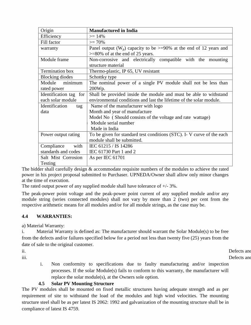
Origin Manufactured in India
Efficiency >= 14%
Fill factor >= 70%
warranty Panel output (Wp) capacity to be >=90% at the end of 12 years and
>=80% of at the end of 25 years.
Module frame Non-corrosive and electrically compatible with the mounting
structure material
Termination box Thermo-plastic, IP 65, UV resistant
Blocking diodes Schottky type
Module minimum
rated power
The nominal power of a single PV module shall not be less than
200Wp.
Identification tag for
each solar module
Shall be provided inside the module and must be able to withstand
environmental conditions and last the lifetime of the solar module.
Identification tag
data
a) Name of the manufacturer with logo
Month and year of manufacture
Model No ( Should consists of the voltage and rate wattage)
b) Module serial number
c) Made in India
Power output rating To be given for standard test conditions (STC). I- V curve of the each
module shall be submitted.
Compliance with
standards and codes
IEC 61215 / IS 14286
IEC 61730 Part 1 and 2
Salt Mist Corrosion
Testing
As per IEC 61701
The bidder shall carefully design & accommodate requisite numbers of the modules to achieve the rated
power in his project proposal submitted to Purchaser. UPNEDA/Owner shall allow only minor changes
at the time of execution.
The rated output power of any supplied module shall have tolerance of +/- 3%.
The peak-power point voltage and the peak-power point current of any supplied module and/or any
module string (series connected modules) shall not vary by more than 2 (two) per cent from the
respective arithmetic means for all modules and/or for all module strings, as the case may be.
4.4 WARRANTIES:
a) Material Warranty:
i. Material Warranty is defined as: The manufacturer should warrant the Solar Module(s) to be free
from the defects and/or failures specified below for a period not less than twenty five (25) years from the
date of sale to the original customer.
ii. Defects and/or failures due to manufacturing
iii. Defects and/or failures due to quality of materials
i. Non conformity to specifications due to faulty manufacturing and/or inspection
processes. If the solar Module(s) fails to conform to this warranty, the manufacturer will
replace the solar module(s), at the Owners sole option.
4.5 Solar PV Mounting Structure
The PV modules shall be mounted on fixed metallic structures having adequate strength and as per
requirement of site to withstand the load of the modules and high wind velocities. The mounting
structure steel shall be as per latest IS 2062: 1992 and galvanization of the mounting structure shall be in
compliance of latest IS 4759.

4.6 Detailed specifications for the mounting structure are given below:
Wind velocity withstanding
capacity
150 km / hour
The designs have been certified by a recognized Lab/
Institution/certified engineers in this regard and submit wind
loading calculation sheet to users if they desire so. Suitable
fastening arrangement such as grouting and calming should be
provided to secure the installation against the specific wind
speed.
Structure material Pre galvanized sheet steel with a minimum galvanization
thickness of 80 microns and the structural patterns shall be made
before galvanizing
Bolts, nuts, panel mounting
clamps, fasteners
(with spring washers)
Stainless steel SS 304
Mounting arrangement for
metal sheet roofs
Mounting directly on the sheet metal, ensuring stability and wind withstanding capacity or penetrating the sheet metal and fixing to the sub-structure, ensuring that the roof remains water proof and ensuring stability and wind withstanding capacity.
Mounting arrangement for
elevated structures
The elevated structure has to be securely anchored to the
supporting surface. Concrete foundations of appropriate weight
and depth for elevated structures mounted directly on the ground;
Bolted with anchor bolts of appropriate strength for elevated
structures mounted on RCC surfaces.
Mounting arrangement for
ground installations
With removable concrete ballast made of pre-fabricated PCC
(1:2:4), M15; assuring enough ground clearance to prevent
damage of the module through water, animals and other
environmental factors.
Mounting arrangement for
RCC-flat roofs Installation
With removable concrete ballast made of pre-fabricated PCC
(1:2:4), M15. The structures shall be designed for simple
mechanical on-site installation. There shall be no requirement
of welding or complex machinery at the installation site.
Minimum distance between
roof edge and mounting
structure
0.5m
Access for panel cleaning
and maintenance
All solar panels must be accessible from the top for cleaning and
from the bottom for access to the module- junction box.
Panel tilt angle North – south orientation with a fixed tilt angle of 27-30
degrees(depending on location), south facing. However to
accommodate more capacity the angle inclination may be reduced
until the plant meets the specified performance ratio requirements. Regarding civil structures the bidder need to take care of the load bearing capacity of the roof and need
arrange suitable structures based on the quality of roof.
The total load of the structure (when installed with PV modules) on the terrace should be less than 60
kg/m2. The array structure shall be grounded properly using maintenance free earthing kit suitable for
mounting over building terrace

4.7 Solar Array Fuse
The cables from the array strings to the solar grid inverters shall be provided with DC fuse protection.
Fuses shall have a voltage rating and current rating as required. The fuse shall have DIN rail mountable
fuse holders and shall be housed in thermoplastic IP 65 enclosures with transparent covers.
4.8 Solar Grid Inverter
As SPV array produce direct current electricity, it is necessary to convert this direct current into
alternating current and adjust the voltage levels to match the grid voltage. Conversion shall be achieved
using an electronic Inverter and the associated control and protection devices. All these components of the
system are termed the “Power Conditioning Unit (PCU)”. In addition, the PCU shall also house MPPT
(Maximum Power Point Tracker). Inverter output should be compatible with the grid frequency. Typical
technical features of the inverter shall be as follows:
1 Total output power (AC To match solar PV plant capacity while achieving
optimum system efficiency
2 Input DC voltage range As required for the solar grid inverter DC input
3 Maximum power point
(MPPT)
Shall be incorporated
4 Number of independent
MPPT inputs
1 or more
5 Operation AC voltage For up to 5kWp - Single phase 230V
For above 5kWp upto 50KW/63KVA –Three
phase
415V four wire Above 50 KW-11KV or as per
availability of the main grid supply
6 Operating Frequency range 47.5 – 52.5 Hz
7 Nominal frequency 50 Hz
8 Power factor of the inverter >0.98 at nominal power
9 Total harmonic distortion Less than 3%
10 Built-in Protection AC high / low voltage; AC high /low frequency
11 Anti-islanding protection As per VDE 0126-1-1 / IEC 60255.5/
IEC 60255.27 / IEC 62116
12 Operating ambient
temperature range
-1 oC to +55
oC
13 Humidity 0 – 95% Rh
14 Inverter efficiency >=95%
15 Inverter weighted efficiency >=94%
16 Protection degree IP 65 for outdoor mounting, IP 54 for indoor
mounting
17 Communication interface RS 485 / RS 232 / RJ45
18 Safety compliance IEC 62109-1, IEC 62109-2
19 Environmental Testing IEC 60068-2 (1, 2, 14, 30)
20 Efficiency Measurement
Procedure
IS/IEC 61683
21 Cooling Convection
22 Display type LCD for data display. LCD /LED for status
display
23 Display parameters to
include
Output power(W), cumulative energy (Wh),
DC voltage (V), DC current (A),

AC voltage (V), AC frequency (Hz),
AC current (A), cumulative hours of operation
(h).
The combined wattage of all inverters should not be less than rated capacity of power plant under
STC.
Maximum power point tracker shall be integrated in the PCU/inverter to maximize energy drawn
from the array. While designing the PCU for UTTAR PARADESH grid comparability the boundary
conditions specified in the UPERC/Secretary/RSPV Regulations /2015/2150 Dated: 20/03/2015 can be
taken care. The details can be downloaded from UPERC web site.
In case of Battery backup the PCU should be of following specifications
PCU Specification for Battery Backup
A SOLAR CHARGE CONTROLLER (SCC)
1 Charge Controller Type MPPT
2 PV Nominal Capacity (Total) (kWp) Same rating as the Inverter Rating
3 No of MPPT Channels Min 1
4 Battery Type Supported LMLA/VRLA
5 Min. Battery AH Required (AH) to be filled by the bidder
6 Min Charging Efficiency (%) 94%
B SOLAR INVERTER
3 Battery back up Capacity Equivalent to 1 hour of inverter rating
4 Nominal Battery Voltage (VDC) As per Inverter Manufacturer
6 Nominal Capacity (KW) Inverter Rated capacity shall be at0.8 PF
8 Voltage Regulation (in Standalone Mode) (%) +/- 2
9 Frequency Regulation (in Standalone Mode)
(Hz)
+/- 0.5
10 THD (%) < than 5
11 Efficiency: Peak/100% Load/20% Load (%) >88 / >85 / >80
12 Load Power Factor 0.8 lag to unity
13 Over Loads: 60 secs/50 secs/5 secs (%) 110 / 125 / 150
14 M in Phase imbalance capability (%) 30
15 Auto Bypass Feature To Be provided
16 Parallel Operation with Grid/ DG To Be provided
17 Power Export to Grid Facility To Be provided
18 Galvanic Isolation Through Isolation Transformer
19 Zero export to Grid facility To Be provided
20 Anti Islanding from Grid To Be provided
C GRID CHARGER
1 Grid Voltage Sync Range (%) +10% to - 20%
2 Grid Frequency Sync Range +5% to - 5%
3 Max Grid Import Power (kW) Same as inverter Rating
4 Max Battery Amps during Grid charging
(Amps)
Shall be 40% of solar charging capacity
but clamped to 20% of the solar
charging capacity
D INDICATION & PROTECTION
1 Type of User Interface with Key PAD LCD based UI interface with
Alphnumeric indications
2 Display Parameters Battery voltage/current
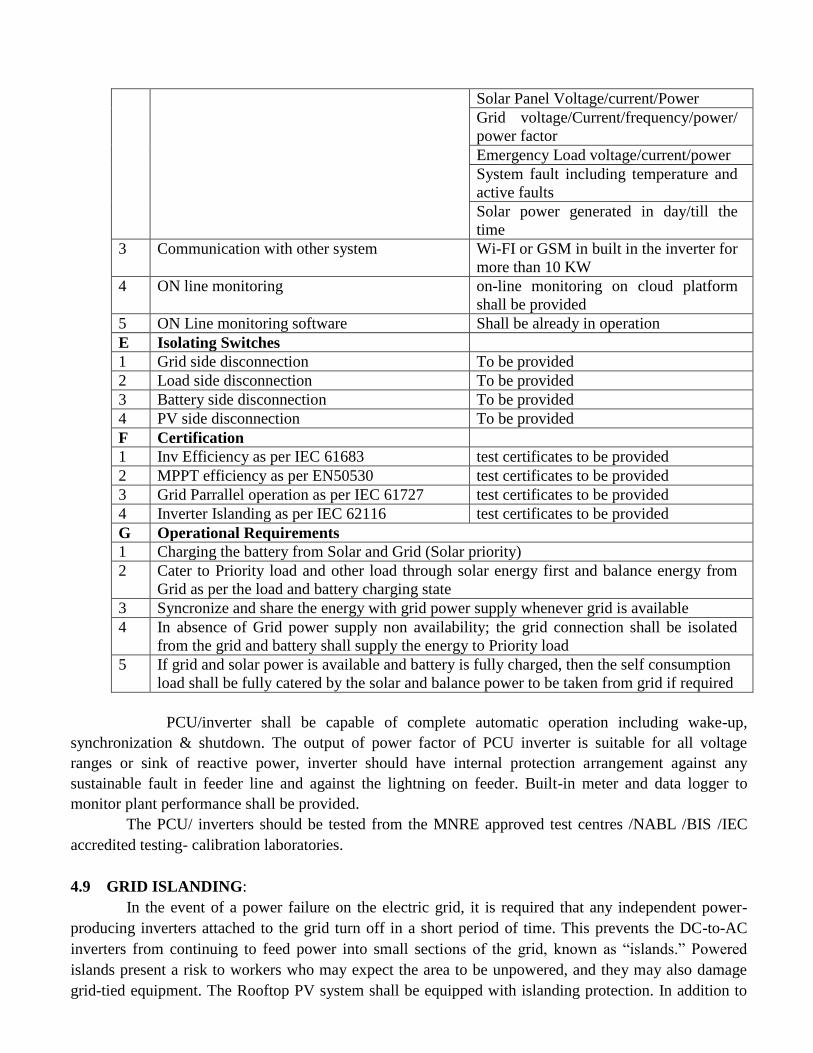
Solar Panel Voltage/current/Power
Grid voltage/Current/frequency/power/
power factor
Emergency Load voltage/current/power
System fault including temperature and
active faults
Solar power generated in day/till the
time
3 Communication with other system Wi-FI or GSM in built in the inverter for
more than 10 KW
4 ON line monitoring on-line monitoring on cloud platform
shall be provided
5 ON Line monitoring software Shall be already in operation
E Isolating Switches
1 Grid side disconnection To be provided
2 Load side disconnection To be provided
3 Battery side disconnection To be provided
4 PV side disconnection To be provided
F Certification
1 Inv Efficiency as per IEC 61683 test certificates to be provided
2 MPPT efficiency as per EN50530 test certificates to be provided
3 Grid Parrallel operation as per IEC 61727 test certificates to be provided
4 Inverter Islanding as per IEC 62116 test certificates to be provided
G Operational Requirements
1 Charging the battery from Solar and Grid (Solar priority)
2 Cater to Priority load and other load through solar energy first and balance energy from
Grid as per the load and battery charging state
3 Syncronize and share the energy with grid power supply whenever grid is available
4 In absence of Grid power supply non availability; the grid connection shall be isolated
from the grid and battery shall supply the energy to Priority load
5 If grid and solar power is available and battery is fully charged, then the self consumption
load shall be fully catered by the solar and balance power to be taken from grid if required
PCU/inverter shall be capable of complete automatic operation including wake-up,
synchronization & shutdown. The output of power factor of PCU inverter is suitable for all voltage
ranges or sink of reactive power, inverter should have internal protection arrangement against any
sustainable fault in feeder line and against the lightning on feeder. Built-in meter and data logger to
monitor plant performance shall be provided.
The PCU/ inverters should be tested from the MNRE approved test centres /NABL /BIS /IEC
accredited testing- calibration laboratories.
4.9 GRID ISLANDING:
In the event of a power failure on the electric grid, it is required that any independent power-
producing inverters attached to the grid turn off in a short period of time. This prevents the DC-to-AC
inverters from continuing to feed power into small sections of the grid, known as “islands.” Powered
islands present a risk to workers who may expect the area to be unpowered, and they may also damage
grid-tied equipment. The Rooftop PV system shall be equipped with islanding protection. In addition to

disconnection from the grid (due to islanding protection) disconnection due to under and over voltage
conditions shall also be provided.
A manual disconnect 4pole isolation switch beside automatic disconnection to grid would have
to be provided at utility end to isolate the grid connection by the utility personnel to carry out any
maintenance. This switch shall be locked by the utility personnel
The AC output of the solar grid inverter shall be connected to the building’s electrical system after the
Discom service connection meter and main switch on the load side. The solar grid inverter output shall be
connected to a dedicated module in the Main Distribution Board (MDB) of the building. It shall not be
connected to a nearby load.
Utilities may have voltage levels other than above, DISCOMS may be consulted before finalization of the
voltage level and specification be made accordingly. For large PV system (Above 100 kW) for
commercial installation having large load, the solar power can be generated at low voltage levels and
stepped up to 11 kV level through the step up transformer. The transformers and associated switchgear
would require to be provided by the SPV bidders.
4.10 DATA ACQUISITION SYSTEM / PLANT MONITORING
(for the plant 10 KW and above )
Data Logging Provision for plant control and monitoring, time and date stamped system data logs for
analysis with the high quality, suitable PC, Metering and Instrumentation for display of systems
parameters and status indication to be provided. Solar Irradiance: An integrating Pyranometer / Solar cell
based irradiation sensor (along with calibration certificate) provided, with the sensor mounted in the plane
of the array. Readout integrated with data logging system. Temperature: Temperature probes for
recording the Solar panel temperature and/or ambient temperature to be provided complete with readouts
integrated with the data logging system The following parameters are accessible via the operating
interface display in real time separately for solar power plant:
AC Voltage.
AC Output current.
Output Power
Power factor.
DC Input Voltage.
DC Input Current.
Time Active.
Time disabled.
Time Idle.
Power produced
Protective function limits (Viz-AC Over voltage, AC Under voltage, Over frequency, Under
frequency ground fault, PV starting voltage, PV stopping voltage.
All major parameters available on the digital bus and logging facility for energy auditing
through the internal microprocessor and read on the digital front panel at any time) and logging
facility (the current values, previous values for up to a month and the average values) should be
made available for energy auditing through the internal microprocessor and should be read on the
digital front panel. PV array energy production: Digital Energy Meters to log the actual value of
AC/ DC voltage, Current & Energy generated by the PV system provided. Energy meter along
with CT/PT should be of 0.5 accuracy class. Computerized DC String/Array monitoring and AC
output monitoring shall be provided as part of the inverter and/or string/array combiner box or
separately. String and array DC Voltage, Current and Power, Inverter AC output voltage and

current (All 3 phases and lines), AC power (Active, Reactive and Apparent), Power Factor and
AC energy (All 3 phases and cumulative) and frequency shall be monitored. Computerized AC
energy monitoring shall be in addition to the digital AC energy meter. The data shall be recorded
in a common work sheet chronologically date wise. The data file shall be MS Excel compatible.
The data shall be represented in both tabular and graphical form. All instantaneous data shall be
shown on the computer screen. Software shall be provided for USB download and analysis of DC
and AC parametric data for individual plant. Provision for Internet monitoring and download of
data shall be also incorporated.
Remote Server and Software for centralized Internet monitoring system shall be also
provided for download and analysis of cumulative data of all the plants and the data of the solar
radiation and temperature monitoring system. Ambient / Solar PV module back surface
temperature shall be also monitored on continuous basis. Simultaneous monitoring of DC and AC
electrical voltage, current, power, energy and other data of the plant for correlation with solar and
environment data shall be provided. Remote Monitoring and data acquisition through Remote
Monitoring System software at the owner/ UPNEDA Lucknow with latest software/hardware
configuration and service connectivity for online / real time data monitoring/control complete to
be supplied and operation and maintenance/control to be ensured by the supplier. Provision for
interfacing these data on UPNEDA server and portal in future shall be kept.
4.11 TRANSFORMER “IF REQUIRED” & METERING:
Dry/oil type relevant kVA, 11kV/415V, 50 Hz Step up along with all protections,
switchgears, Vacuum circuit breakers, cables etc. along with required civil work. The bidirectional
electronic energy meter (0.5 S class) shall be installed for the measurement of import/Export of energy.
The bidder must take approval/NOC from the Concerned DISCOM for the connectivity, technical
feasibility, and synchronization of SPV plant with distribution network and submit the same to UPNEDA
before commissioning of SPV plant.
Reverse power relay shall be provided by bidder (if necessary), as per the local DISCOM
requirement.
4.12 Battery Backup:
The system may also be installed by consumers with battery backup. The capacity of battery
bank should be designed for 1 hr backup for capacity of invertor considering the maximum DOD 75% for
lead acid tubular plate or as per design to get minimum 5 years life. The voltage of battery may be
selected according to the PCU design. Battery shall be flooded electrolyte Tubular Low Maintenance
Lead Acid /VRLA type .The batteries should conform to IS 1651 / IS 13369/ . Capacity of the battery
bank shall not be less than as specified above at C10 rate. The battery should be warranted for minimum
5 years. The battery should be installed inside the premises of consumers on a Battery rack of acid
resistant material to bear the required battery load. The non-reactive acid proof mat should be
provided around the floor space of battery bank.
A copy of the relevant test certificate for the battery should be furnished.
4.13 POWER CONSUMPTION: Regarding the generated power consumption, priority need to give for internal consumption
first and thereafter any excess power can be exported to grid..
4.14 PROTECTIONS
The system should be provided with all necessary protections like earthing, Lightning, and grid
islanding as follows:
4.15 LIGHTNING PROTECTION

The SPV power plants shall be provided with lightning & overvoltage protection. The main aim
in this protection shall be to reduce the over voltage to a tolerable value before it reaches the PV or other
sub system components. The source of over voltage can be lightning, atmosphere disturbances etc The
entire space occupying the SPV array shall be suitably protected against Lightning by deploying required
number of Lightning Arrestors. Lightning protection should be provided as per IEC 62305 /IS 2309
standard. The protection against induced high-voltages shall be provided by the use of metal oxide
varistors (MOVs) and suitable earthing such that induced transients find an alternate route to earth.
4.16 SURGE PROTECTION
Surge protection shall be provided on both the DC and the AC side of the solar system. The
DC surge protection devices (SPDs) shall be installed in the DC distribution box adjacent to the solar grid
inverter.
The AC SPDs shall be installed in the AC distribution box adjacent to the solar grid inverter. The
SPDs earthing terminal shall be connected to earth through the above mentioned dedicated earthing
system. The SPDs shall be of type 2 as per IEC 60364-5-53 4.17 EARTHING PROTECTION
(a) Each array structure of the PV yard should be grounded/ earthed properly as per IS:3043-
1987. In addition the lighting arrester/masts should also be earthed inside the array field.
Earth Resistance shall be tested in presence of the representative of Discom /UPNEDA as
and when required after earthing by calibrated earth tester. PCU, ACDB and DCDB should
also be earthed properly.
(b) Earth resistance shall not be more than 5 ohms. It shall be ensured that all the earthing points
are bonded together to make them at the same potential.
4.18 CABLES
Cables of appropriate size to be used in the system shall have the following characteristics:
a) Shall meet IEC 60227/IS 694, IEC 60502/IS1554 standards Temp. Range: –10oC to +80
oC.
Voltage rating 660/1000V
b) For the DC cabling, Solar cables with multi stranded copper conductors XLPE or XLPO
insulated and sheathed with the voltage rating of 1000 V DC or higher UV stabilised single
core flexible copper cables shall be used. Multi-core cables shall not be used.
c) For the AC cabling, PVC or XLPE insulated and PVC sheathed single or multi-core flexible
copper cables shall be used. Outdoor AC cables shall have a UV-stabilised outer sheath
d) The total voltage drop on the cable segments from the solar PV modules to the solar grid
inverter shall not exceed 1.0%.
e) The total voltage drop on the cable segments from the solar grid inverter to the building
distribution board shall not exceed 2.0%
f) The DC cables from the SPV module array shall run through a UV-stabilised PVC conduit
pipe of adequate diameter with a minimum wall thickness of 1.5mm or through a High
Density Poly Ethylene (HDPE) conduit. The conduits shall not run across the path way of
the terrace. Flexible corrugated PVC conduits shall not be used.
g) Cables and wires used for the interconnection of solar PV modules shall be provided with
solar PV connectors (MC4) and couplers.
h) All cables and conduit pipes shall be clamped to the rooftop, walls and ceilings with
thermo-plastic clamps at intervals not exceeding 50 cm. The minimum DC cable size shall

be 4.0 mm2 copper. The minimum AC cable size shall be 4.0 mm
2 copper for up to 10kWp
and 16.0mm2 for above 10kWp / required standard size. In three phase systems, the size of
the neutral wire shall be equal to the size of the phase wires. The following colour coding
shall be used for cable wires:
i) DC positive: red (the outer PVC sheath can be black with a red line marking)
j) DC negative: black
k) AC single phase: Phase: red; neutral: black
l) AC three phase: Phases: red, yellow, blue; neutral: black Earth wires: green
m) Cables and conduits that have to pass through walls or ceilings shall be taken through
a PVC pipe sleeve.
n) Cable conductors shall be terminated with tinned copper end-ferrules to prevent fraying
and breaking of individual wire strands. The termination of the DC and AC cables at
the Solar Grid Inverter shall be done as per instructions of the manufacturer, which in
most cases will include the use of special connectors.
o) Cable lugs and end –ferrules for all cable conductor and wire terminations shall be
crimped with crimping pliers and end-ferrule pliers
p) All cable ties shall be UV resistant.
q) The Cable should be so selected that it should be compatible up to the life of the solar
PV panels i.e. 25years
r) The ratings given are approximate. Bidder to indicate size and length as per system
design requirement. All the cables required for the plant provided by the bidder. Any
change in cabling sizes if desired by the bidder/approved after citing appropriate
reasons. All cable schedules/layout drawings approved prior to installation.
4.19 TOOLS & TACKLES AND SPARES: After completion of installation & commissioning of the power plant, necessary tools &
tackles are to be provided free of cost by the bidder for maintenance purpose.
4.20 DANGER BOARDS AND SIGNAGES: Danger boards should be provided as and where necessary as per IE Act. /IE rules as
amended up to date. Three signage shall be provided one each at battery –cum- control room, solar array
area and main entry from administrative block. Text of the signage may be finalized in consultation with
UPNEDA/ owner.
4.21 FIRE EXTINGUISHERS: The firefighting system for the proposed power plant for fire protection shall be consisting
of: Portable fire extinguishers in the control room for fire caused by electrical short circuits Sand buckets
in the control room The installation of Fire Extinguishers should confirm to TAC regulations and BIS
standards. The fire extinguishers shall be provided in the control room housing PCUs as well as on the
Roof or site where the PV arrays have been installed.
4.22 DRAWINGS & MANUALS: Two sets of Engineering, electrical drawings and Installation and O&M manuals are to be
supplied.
4.23 PLANNING AND DESIGNING: The bidder should carry out Shadow Analysis at the site and accordingly design strings & arrays layout
considering optimal usage of space, material and labor.

4.24 SOLAR PV SYSTEM ON THE ROOFTOP FOR MEETING THE ANNUAL ENERGY
REQUIREMENT The Solar PV system on the rooftop of the selected buildings will be installed for meeting the annual
energy requirements depending upon the area of rooftop available and the remaining energy requirement
of the office buildings will be met by drawing power from grid at commercial tariff of DISCOMs.
4.25 SAFETY MEASURES: The bidder shall take entire responsibility for electrical safety of the installation(s) including connectivity
with the grid and follow all the safety rules & regulations applicable as per Electricity Act, 2003 and
CEA guidelines etc.
4.26 DC Combiner Box
A DC Combiner Box shall be used to combine the DC cables of the solar module arrays with DC fuse
protection for the outgoing DC cable(s) to the DC Distribution Box.
4.27 DC Distribution Box
A DC distribution box shall be mounted close to the solar grid inverter. The DC distribution box shall be
of the thermo-plastic IP65 DIN-rail mounting type and shall comprise the following components and
cable terminations:
Incoming positive and negative DC cables from the DC Combiner Box;
DC circuit breaker, 2 pole (the cables from the DC Combiner Box will be connected to this
circuit breaker on the incoming side);
DC surge protection device (SPD), class 2 as per IEC 60364-5-53;
Outgoing positive and negative DC cables to the solar grid inverter.
As an alternative to the DC circuit breaker a DC isolator may be used inside the DC Distribution Box or
in a separate external thermoplastic IP 65 enclosure adjacent to the DC Distribution Box. If a DC isolator
is used instead of a DC circuit breaker, a DC fuse shall be installed inside the DC Distribution Box to
protect the DC cable that runs from the DC Distribution Box to the Solar Grid Inverter.
4.28 AC Distribution Box An AC distribution box shall be mounted close to the solar grid inverter. The AC distribution box shall be
of the thermo plastic IP65 DIN rail mounting type and shall comprise the following components and
cable terminations:
Incoming 3-core / 5-core (single-phase/three-phase) cable from the solar grid inverter
AC circuit breaker, 2-pole / 4-pole AC surge protection device (SPD), class 2 as per IEC
60364-5-53
4.29 Metering The existing service connection meter needs to be replaced with a bidirectional (import kWh and export
kWh) service connection meter for the purpose of net-metering for eligible categories. Installation of the
net meter will be carried out by Discom. Beneficiary will submit application to Discom to enable the
connectivity of Solar rooftops with Grid and to avail net metering benefits. The beneficiaries can also
purchase the Net meter from market and get it install by the DISCOM.
4.30 Documentation
The Installer shall supply the following documentation: i. System description with working principles.
ii. System single line diagram.
iii. Solar PV array lay-out.

iv. Routing diagram of cables and wires.
v. Data sheets and user manuals of the solar PV panels and the solar grid inverter.
vi. A system operation and maintenance manual.
vii. Name, address, mobile number and email address of the service centre to be
contacted in case of failure or complaint.
viii. Warranty cards.
ix. Maintenance registers.
4.31 Test Certificates and Reports to be Furnished
Test Certificates / Reports from IECQ / NABL accredited laboratory for relevant IEC / equivalent BIS
standard for quoted components shall be furnished. Type Test Certificates / reports shall be provided for
the solar modules and solar grid tied inverters up to 20kW to provide evidence of compliance with
standards. For solar grid tied inverters above 20kW, self-certification by the manufacturer of the
said inverter is acceptable.
4.32 General Instructions
A Water and power supply for the construction shall be the responsibility of the
Contractor/Bidder
B Security, safety, watch, and ward of all materials at sites shall be the responsibility of the
Contractor/Bidder
C Liaison with the concerned distribution licensees, Uttar Pradesh New and Renewable
Energy Development Agency, Roof Owner (concerned Beneficiary), the Chief Electrical
Inspector and any other statutory authorities as applicable for all the Project approvals
D Expenses for any other works, supply of material, and providing services required for the
successful commissioning and operation of the plant, but not specifically mentioned in
this document.
E Safety management to be strictly complied with by the Contractor/Bidder throughout
implementation activity.
F First-aid medical facilities at the Site during construction to be provided by the
Contractor/ Bidder(s)
G All local labour, employment, and other issues shall be handled independently by the
Contractor/ Bidder(s)
H The entire responsibility and risk relating towards the workforce working at the Site, and
compliance of different statutory regulations like Workman Compensation Act,
Employees’ State Insurance Corporation (ESIC), Factory Act 1948, Contract
LabourRegulation, and Abolition Act 1970, Shop and Establishment Act 1948, and other
Statutory regulatory bodies shall solely lie with the Contractor/ Bidder(s).
I I. The Contractor/ Bidder(s) shall also be solely responsible for payment of wages,
provident fund, bonus, retrenchment compensation leave, etc. applicable as per various
statutory regulations to their entire workforce,
4.33 The following Statutory Clearances shall be obtained by the/Bidder(s) wherever applicable:
a) Drawings approvals from Beneficiary .
b) Electrical Safety approval for system more than 10 KW (Chief Electrical Inspector)
a) All equipment, accessories, materials, civil construction & erection works should comply
with statutory requirements, BIS and required and highlighted IEC standards
4.34

4.34.1. The Contractor/ Bidder(s)should not misuse the area and/or assign responsibility for the safety
of machinery within the premises.
4.35 Term 4.35.1 The term for operation and maintenance of the plant may be extended for another five
years on mutually agreed terms and conditions and charges.
4.36 Electricity Generation
The Contractor/Bidder shall be solely responsible for the performance of the plant(s) and shall make all
necessary efforts to maximize the electricity generation of the plant.
4.37 Metering and associated facilities
The metering of electricity shall be carried out as per the regulations stipulated by Uttar Pradesh
Electricity Regulatory Commission and/or Central Electricity Authority.
4.38 Failure to rectify the problem
a). If the Contractor/ Bidder(s) fails to rectify the plant downtime within seven (7) days from the
date of identification of such defect, unless the extension in time is mutually discuss and agreed between
the bidder and the respective Beneficiary.
b) If the Contractor/Bidder(s)fails to rectify the problem, the respective Beneficiary shall/may rectify
the problem at the expense of the Contractor/ Bidder(s), in such case on genuine complaint, UPNEDA
will take appropriate action including forfeiture of PBG and blacklisting/debarring of the firm.
4.39 Completion of Term
On completion of the term of Operation and Maintenance the Contractor/ Bidder(s) shall
apply to the respective Beneficiary for the issue of power plant performance certificate.
Such document is required for release of PBG of the firm.
Make of Module, Battery and PCU in technical bid will be indicative, bidder can use its
equivalent as per MNRE test report/guidelines and submits its details test report before
execution.

4.40 Standards and Limits
Following specifications shall be applicable for the activities related to meters and grid
interconnection.
Standards and Limits
PARAMETER REFERENCE REQUIREMENT
Service
conditions
Relevant regulation/order by Uttar Pradesh Electricity Regulatory Commission Compliance
Overall Grid
Standards
Central Electricity Authority (Grid
Standard) regulations 2010
Compliance
Equipment BIS / IEEE / IEC Compliance
Meters Central Electricity Authority
(Installation and Operation of Meters)
Regulation 2013 & relevant
regulations by Uttar Pradesh
Electricity Regulatory Commission
Compliance
Safety and
Supply
Central Electricity Authority
(Measures of Safety and Electricity
Supply) Regulation 2010
Compliance
Harmonic
Current
IEEE 519 and CEA (Technical
Standards for Connectivity of the
Distributed Generation Resources)
Regulations 2013
Harmonic current injections from a
generating station shall not exceed
the limits specified in IEEE 519
Synchroniza
tion
IEEE 519 and CEA (Technical
Standards for Connectivity of the
Distributed Generation Resources)
Regulations 2013
Photovoltaic system must be
equipped with a grid frequency
synchronization device. Every time
the generating station is
synchronized to the electricity
system. It shall not cause voltage
fluctuation greater than +/- 5% at
point of connection.
Voltage IEEE 519 and CEA(Technical
Standards for Connectivity of the
Distributed Generation Resources)
Regulations 2013
The voltage-operating window
should minimize nuisance tripping
and should be under operating
range of 80% to110% of the
nominal connected voltage. Beyond
a clearing time of 2 second, the
photovoltaic system must isolate
itself from the grid.
Flicker IEEE 519 and CEA (Technical
Standards for Connectivity of the
Distributed Generation Regulations
2013 Resources)
Operation of Photovoltaic system
should not cause voltage flicker in
excess of the limits stated in IEC
61000 standards or other equivalent
Indian standards, if any.
Frequency IEEE 519 and CEA (Technical
Standards for Connectivity of the
Distributed Generation Resources).
Regulations 2013
When the Distribution system
frequency deviates outside the
specified conditions(50.5 Hz on
upper side and 47.5 Hz on lower
side), There should be over and under
frequency trip functions with a
clearing time of 0.2 seconds

DC injection IEEE 519 and CEA (Technical
Standards for Connectivity of the
Distributed Generation Resources).
Regulations 2013
Photovoltaic system should not inject
DC power more than0.5% of full
rated output at the interconnection
point under any operating conditions
Power
Factor
IEEE 519 and CEA (Technical
Standards for Connectivity of the
Distributed Generation Resources).
Regulations 2013
While the output of the inverter is
greater than 50%, a lagging power
factor of greater than 0.9 should
operate
Islanding
and
Disconnectio
n
IEEE 519 and CEA (Technical
Standards for Connectivity of the
Distributed Generation Resources).
Regulations 2013
The photovoltaic system in the event
of fault, voltage or frequency
variations must island / disconnect
itself within IEC standard on
stipulated period
Overload
and
Overheat
IEEE 519 and CEA (Technical
Standards for Connectivity of the
Distributed Generation Resources).
Regulations 2013
The inverter should have the
facility to automatically switch off in
case of overload or overheating and
should restart when normal conditions
are restored
Paralleling
Device
IEEE 519 and CEA (Technical
Standards for Connectivity of the
Distributed Generation Resources).
Regulations 2013
Paralleling device of photovoltaic
system shall be capable of
withstanding 220% of the normal
voltage at the interconnection point.
Notes for Bidder:
1. The installation should not be protruding outside the building and there should not be
overhang type structure on any terrace.
2. Location and area for inverter and other interconnection equipment should be located in
suitable and secure place and this should be approved by the respective Beneficiary.
3. Installation diagram and wiring from array to proposed location of inverter and
interconnection should be clearly presented by the Empaneled Bidder before work starts
on the site if desired by the beneficiaries. These should be approved by owner of the
respective building.
4. Any installations on the terrace should be planned and executed in such a way that water
proofing will not be disturbed and harmed. In case any area water proofing is affected it
will be Bidders's responsibility to correct it and put it right.
5. CONFIRMATION TO MNRE TECHNICAL SPECIFICATIONS AND STANDARDS
The Tenderer should ensure that all components and systems used under this Scheme shall strictly
adhere to the Technical Specifications and Guidelines issued by MNRE, and as amended from time to
time.
QUALITY CERTIFICATION, STANDARDS AND TESTING FOR GRID-CONNECTED ROOFTOP SOLAR PV SYSTEMS/POWER PLANTS
Quality certification and standards for grid-connected rooftop solar PV systems are essential
for the successful mass-scale implementation of this technology. It is also imperative to put
in place an efficient and rigorous monitoring mechanism, adherence to these standards.

Hence, all components of grid-connected rooftop solar PV system/ plant must conform to
the relevant standards and certifications given below:
Solar PV Modules/ Panels
IEC 61215/ IS 14286 Design Qualification and Type Approval for
Crystalline Silicon Terrestrial Photovoltaic
(PV) Modules
IEC 61701 Salt Mist Corrosion Testing of Photovoltaic
(PV) Modules
IEC 61853- Part 1/ IS 16170: Part 1 Photovoltaic (PV) module performance
testing and energy rating –: Irradiance and
temperature performance
measurements,
and power rating
IEC 62716 Photovoltaic (PV) Modules –
Ammonia (NH3) Corrosion
Testing
(As per the site condition like dairies,
toilets)
IEC 61730-1,2 Photovoltaic (PV) Module Safety
Qualification – Part 1: Requirements for
Construction, Part 2: Requirements
for
Testing
Solar PV Inverters
IEC 62109-1, IEC Safety of power converters for use in
62109-2 photovoltaic power systems –
Part 1: General requirements, and Safety of

power converters for use in photovoltaic
power systems
Part 2: Particular requirements for inverters.
Safety compliance (Protection degree IP 65
for outdoor mounting, IP 54 for indoor
mounting)
IEC/IS 61683 Photovoltaic Systems – Power conditioners:
(as applicable) Procedure for Measuring Efficiency (10%,
25%, 50%, 75% & 90-100% Loading
Conditions)
IEC 62116/ UL 1741/ IEEE 1547 Utility-interconnected Photovoltaic Inverters -
(as applicable) Test Procedure of Islanding Prevention
Measures
IEC 60255-27 Measuring relays and protection equipment –
Part 27: Product safety requirements
IEC 60068-2 / IEC 62093 Environmental Testing of PV System –
(as applicable) Power Conditioners and Inverters
Fuses
IS/IEC 60947 (Part 1, 2 & 3), EN General safety requirements for connectors,
50521 switches, circuit breakers (AC/DC):
a) Low-voltage Switchgear and
Control-

WARRANTY AND MAINTENANCE
1. The PV modules will be warranted for a minimum period of 25 years from the date of
supply. (Output wattage should not be less than 90% at the end of 12 years and 80% at the
end of 25 years).
2. The mechanical structures, electrical components including evacuation infrastructure and
overall workmanship of the Solar PV Rooftop power plant system must be warranted for a
minimum of 5years from the date of commissioning and handing over of the system.
3. The Comprehensive Maintenance (within warranty period) may be executed by the firm
themselves or through the service center of the firm in the concerned district/Division.
4. The contractor/ bidder shall be responsible to replace free of cost (including transportation
and insurance expenses) to the purchaser whole or any part of supply which under normal
and proper use become dysfunctional within 7 days of issue of any such complaint by the
purchaser.
5. The service personnel of the Successful Bidder will make routine quarterly maintenance
visits. The maintenance shall include thorough testing & replacement of any damaged parts
Apart from the any complaint registered/ service calls received / faults notified in the report
generated by the IVRS should be attended to and the system should be repaired/ restored/
replaced within 7 days.
6. Normal and preventive maintenance of the SPV Rooftop Power Plant systems will also be
the duties of the deputed personnel during quarterly maintenance visits.
7. During operation and maintenance period of the SPV Rooftop Power Plant systems, if there
is any loss or damage of any component due to miss management/miss handling or due to
any other reasons pertaining to the deputed personnel, what-so-ever, the supplier shall be
responsible for immediate replacement/rectification. The damaged component may be
repaired or replaced by new component

Financial e-tender NO. 01/UPNEDA/SPV/Grid Connect/Rooftop/2018
Name of the Firm: ------------------------------------------------------------------------------
Design, Supply, Installation, Testing and Commissioning of Grid Connected Rooftop Solar Photovoltaic
Power Plant and power evacuation system and other necessary infrastructures including 5 years Operation,
Comprehensive Warranty and Maintenance of Grid Connected Rooftop Solar Photovoltaic Power Plants and
Power Evacuation system in various Districts in the State of Uttar Pradesh as per technical specifications,
Terms and Conditions of the tender document:-
Lowest Rate (For UPNEDA work order and availing subsidy, The beneficiaries may negotiate
with firm for placing order to firm.)
Sl.
No Description Cost of SPV Power plant per
kWp including CMC for 5
years without battery
backup (Rs)
Cost of SPV power plant Per
kWp Including CMC
for 5 years with Battery Backup (Rs).
A B
1 PART A :
a. 1KW Upto 5 kWp
50000/- 52000/-*
b. 6 KW Upto 10 kWp 50000/- 54500/-*
2 PART B: 11kWp to 100 kWp. 45300/- 53300/-*
3 PART C: 101kWp to 500 kWp 44900/- 49150/-*
*Not for subsidy, subsidy shall be given at the rate without battery as mentioned in column
A
NOTES:
1. Certified that rates quoted above are as per the requirement, specification terms & condition mentioned in the e-tender document.
2. The rates are inclusive of all taxes & duties, storage, transportation up to site, insurance etc., and any other job required to properly execute the work.
(Signature)
With seal

Format of JCR
JOINT COMMISSIONING, HANDING OVER CERTIFICATE&WARRANTY CARD
It is hereby certified that following system with following details has been supplied, installed
and commissioned:-
Sl. Items Details
1 Name of system
2 Agreement number &Date
5 Name of Firm
6 Name of Beneficiary
(with mobile number)
7 District
8 Block
9 Gram Panchayat
10
Exact location on installation Latitude and longitude exactly
11 Date of installation
12 Warrantee expire on
13 Name & Address of the manufacturer/supplier of the
system
14 SPV Modules installed
Sr. No. Use separate sheet
Make Also enclose IEC test certificate
Model Of module.
Module wattage ----------and number of module----
15 Battery
Type Use separate sheet
Sr. No. Enclose battery test report
Make
Model
Battery voltage & Amp hr
16 PCU
Sr. No. Use separate sheet
Make Enclose test report
Model
Capacity
17
Net Metering details
Make
Serial no
Capacity
Enclose test and installation
report from UPPCL
17 Training for operation & maintenance of the system Provided/not provided
18 Technical literature, operation & maintenance Provided/not provided
manual in English/Hindi
(Signature) (Signature) Authorized Signatory of Firm Sr./Project Officer/In charge

(In case of complaint dial toll free number 1800 180 0005)
Certificate from Project Officer Following are certified in reference to work for supply, Installation & commissioning of ----KW Solar Rooftop Solar Power Plant installed by
the supplier M/s…..................................................... 1. The plant/ system has been installed & commissioned in good condition as per technical specification of the agreement. 3. The work has been completed on dated: ….................... 4. Instruction Manual and Guarantee Card have been provided to beneficiaries. 5. The Supplier has provided basic training to the beneficiaries for day to day care & maintenance of the system/ plant. 6. The name, complete address, contact person and contact number along with e-mail address of the supplier has been provided to the beneficiaries.
Signature of the beneficiary Signature of Project Officer/With Seal
(Project officer will retain 01 copies of joint commissioning report, two copies to be sent to beneficiaries)