aiaa scitech 2017 computations of torque … scitech 2017 computations of torque ... torque...
TRANSCRIPT
1
AIAA SciTech 2017
Computations of Torque-Balanced Coaxial Rotor Flows
Seokkwan Yoon,* William M. Chan,* and Thomas H. Pulliam*
NASA Ames Research Center, Moffett Field, California 94035
Interactional aerodynamics has been studied for counter-rotating coaxial rotors in hover. The effects of
torque balancing on the performance of coaxial-rotor systems have been investigated. The three-dimensional unsteady Navier-Stokes equations are solved on overset grids using high-order accurate schemes, dual-time stepping, and a hybrid turbulence model. Computational results for an experimental model are compared to available data. The results for a coaxial quadcopter vehicle with and without torque balancing are discussed. Understanding interactions in coaxial-rotor flows would help improve the design of next-generation autonomous drones.
I. INTRODUCTION Although the first concept of coaxial rotors appeared almost 160 years ago, it has rarely been used because of
manufacturing challenges posed by the increased mechanical complexity of the hub compared to single rotors. Only the Kamov Design Bureau of Russia was successful in production of coaxial rotorcraft in 1970s. However, there is a renewed interest in coaxial rotors due to recent requirements for unmanned aerial vehicles and high-speed rotorcraft.
Multi-rotors are frequently used for electric unmanned aerial systems partly due to their mechanical simplicity and redundancy. Compared to single rotor systems, multi-rotors offer an advantage in lifting capacity because the size of a rotor is limited by the tip speed and structural requirements. Coaxial rotors have started to appear in both small and large multi-rotor configurations. For example, the Ehang 184 (Fig. 1a) from China is the first autonomous rotorcraft designed for human transportation.
In military applications, Russian Kamov models have been operational for more than forty years. Recently, Sikorsky has developed the S-97 Raider based on the X2 technology to demonstrate a high-speed capability with the addition of a pusher propeller. DARPA has been developing a new technology demonstrator called Tern (Fig. 1b) to enable launch, recovery, and operations of an unmanned aircraft system from small littoral combat ships with limited landing areas. Tern, a tail-sitter with a cruciform tail, looks similar to the Convair XFY-1 from the 1950s. It takes off and lands vertically but its whole body tilts for horizontal flight and then coaxial rotors work as counter-rotating propellers.
A coaxial rotor system is defined as having an upper and a lower rotor that rotate in opposite directions.1 In a conventional helicopter that has a main-rotor/tail-rotor combination, the torque generated by the main rotor is countered by the tail rotor thrust. Since reactive moments of coaxial rotors are supposed to be canceled by contra-rotation, no tail rotor is required to counter the torque. Unlike the single main rotor design that distributes power to both main and tail rotors, all of the power for coaxial rotors is used for vertical thrust. Thus, no power is wasted for anti-torque or directional control. The saved power helps coaxial rotors reach a higher hover ceiling than single rotor helicopters. Another advantage of coaxial rotors is that the overall rotor diameter can be reduced for a given vehicle gross weight because each rotor provides a maximum contribution to vertical thrust to overcome vehicle weight.2
Unlike most helicopters with a single main rotor, interactions between the upper and lower rotors emerge as important factors to consider in design because the increase in performance of a multi-rotor system is not simply proportional to the number of rotors. Interference losses and differences in thrust between the upper and lower rotors have been investigated by theoretical methods,3 actuator disk modeling,4 and the Reynolds-Averaged Navier-Stokes (RANS) simulations.5 In a recent study,6 a hybrid turbulence model was used to investigate the effects of inter-rotor spacing and fuselage on the performance and efficiency of coaxial rotor systems.
The lower rotor generates a lower thrust and torque than the upper rotor because the inflow to the lower rotor is influenced by the wake of the upper rotor. Although the difference in torque between the upper and lower rotors provides yaw control in forward flight, it is desirable to balance the torques to avoid unintended yawing motion in hover. In Ref. 6, dual coaxial rotor systems were used to provide directional stability. In the present study, * NASA Advanced Supercomputing Division
https://ntrs.nasa.gov/search.jsp?R=20170000654 2018-05-23T08:41:55+00:00Z

2
differential collectives are used to achieve torque balancing in a coaxial rotor system. The design of an efficient coaxial rotor system requires an accurate assessment of aerodynamic interference
between the rotors. The first objective of the present work is to study the effects of torque balancing on the performance of coaxial rotor systems. The second objective is to compare numerical solutions with the available experimental data.7 Finally, the rotors of the popular DJI Phantom 3 drone have been modified to coaxial quadrotors to assess the effect of torque-balanced coaxial rotors on the performance of a quadcopter vehicle.
II. NUMERICAL METHODS Accurate prediction of rotorcraft performance in hover continues to be challenging for CFD. The flows are
inherently complex because a rotor blade can encounter its own tip vortex and the tip vortices of other blades. The distance from the rotor to the far-field boundary has a significant effect on figure of merit (FM) prediction, a measure of hover efficiency. The asymptotic FM is only reached when the far-field boundary is located at least twenty rotor radii away from the rotor.8 Also, it has been found that twenty to thirty revolutions are often required for a running mean of the FM to reach a quasi-steady state even in free air.
Overset Grid Generation An overset grid approach, Chimera Grid Tools9,10 for grid generation, and OVERFLOW211,12 for computational
solutions, have been employed for the present computational simulations. OVERFLOW solves the Reynolds-Averaged Navier-Stokes (RANS) equations on structured overset grids. The current time-accurate approach consists of an inertial coordinate system where near-body (NB) curvilinear O-grids for the rotor blades and hub are embedded in an off-body (OB) Cartesian grid system. Prescribed motion is applied to the rotor grids, which rotate relative to the fixed off-body Cartesian grids. This study employs the full-size XV-15 isolated rotor grid system used in previous studies.6,8,13,14 A uniformly spaced OB Cartesian grid surrounds the rotor blades and hub and resolves the rotor wake region. Coarser “brick-grids” efficiently expand the grid system to the far field, where each successive brick grid is twice as coarse as its previous neighbor. The XV-15 isolated rotor consists of three highly twisted rotor blades and a simplified hub. Each rotor blade consists of three O-grids, one for the main rotor blade and two “cap-grids” for the inboard and outboard tips. The grid spacing normal to solid surfaces is chosen to maintain y+<1. The resolved wake region has a uniform grid spacing of 10% ctip (rotor blade tip chord length). Care is taken to make sure the NB grid spacing is similar to the OB grid spacing where the grids overlap to maintain accurate inter-grid communication.
The model used in the experiments7 is an XV-15-like twisted blade that has a 1/7 scale dimension in chord but is longer than a scaled XV-15 in length by 1 inch. New grids have been generated based on modified surfaces to accommodate a longer length as well as a large root cutout.
A notional counter-rotating coaxial rotor system is constructed by incorporating two sets of the aforementioned XV-15 or experimental rotor grid systems. Mirroring the counter-clockwise rotor blade generates the clockwise rotor blade. The coaxial rotor system results in approximately 100 - 120 million grid points for the experimental rotor system depending on the inter-rotor spacing. Overset grids for a coaxial quadcopter vehicle that employs eight
(a) (b) Figure 1. Coaxial rotor systems in modern autonomous vertical-lift vehicles. (a) Ehang 184 autonomous aerial vehicle for human transportation (www.ehang.com/ehang184), (b) DARPA Tern unmanned aircraft system for launch from littoral combat ships (www.darpa.mil/program/tern).
3
counter-rotating rotors and fuselage have been generated in a similar fashion. High-Order Accurate Navier-Stokes Solver The Navier-Stokes equations are solved using finite differences with a variety of numerical algorithms and
turbulence models. Up to 6th-order spatial accuracy for inviscid fluxes, up to 7th-order artificial dissipation, and 2nd-order time accuracy are available.11,12 In this study, the diagonal central difference algorithm is used with the 5th-order accurate spatial differencing option (4th order for the quadcopter). Dual time-stepping is used to advance the simulation in time with 2nd-order time accuracy. The physical time step corresponds to 0.25 degrees rotor rotation, together with 50 dual-time sub-iterations. This typically provides for at least 2.5 orders of magnitude drop in the sub-iteration residual. This numerical approach and time step was previously validated for similar isolated rotor flows.8 In order to reduce the computational time required for a converged solution, the first 1,440 steps employ a time step of 2.5 deg, resulting in 10 rotor revolutions. The time step is then reduced to 0.25 deg, so that 1,440 steps then correspond to one rotor revolution.
Low Mach Number Preconditioning One of the challenges for compressible Navier-Stokes methods in computing small-rotor flows is the relatively
low Mach number flow due to small rotor radii. For example, the Mach number at the tip of blades is under 0.17 at 800 rpm for the experimental model rotor. In the case of the DJI Phantom rotor, the Mach number at the tip of blades is under 0.2 at 5,400 rpm. Mach numbers at the inboard locations are obviously even lower. Compressible Navier-Stokes codes in general suffer from slow convergence for low speed flows because of a disparity between the acoustic and convective speeds. Because most numerical algorithms have a stability restriction on the size of the time step determined by the maximum eigenvalue, the acoustic speed limits the time step. On the other hand, convergence to a steady state is controlled by the convective speed, which determines how fast low-frequency errors are advected out of the computational domain. If the convective speed is much smaller than the speed of sound, the stability restriction forces time steps so small that convergence requires a large number of iterations. Low Mach number preconditioning15,16 is an attempt to equilibrate the eigenvalues, making them all of the same order of magnitude and thus decreasing the number of iterations to convergence. Low Mach number preconditioning is only used during the sub-iteration steps at each physical time step for the experimental rotor and the coaxial quadcopter.
Hybrid Turbulence Modeling Rotorcraft simulations using the Detached Eddy Simulation17 (DES) model have been successfully performed
to predict the Figure of Merit (FM) accurately. The RANS equations require a closure by modeling the Reynolds stress. The one-equation Spalart-Allmaras18 RANS model is one of the models commonly used to compute the turbulent eddy viscosity using the Boussinesq approximation to relate the Reynolds stresses to a kinematic turbulent eddy viscosity and the mean strain-rate tensor. The turbulence length scale, d, is defined as the distance from a field point to the nearest wall. The accuracy of this RANS model depends strongly on the source terms, which were primarily developed for attached boundary-layer flows along flat plates, wings, fuselages, etc. The turbulence length scale, d, plays a key role in accurately determining the rotor FM. A problem occurs deep within the rotor wake, where d may be several rotor radii in length. In this case, d no longer represents an estimate of the largest turbulent eddy in the local flow, but rather, a very large geometric parameter. When d is very large the turbulence dissipation becomes very small. On the other hand, the strong tip vortices in the lower wake can generate significant turbulence production. Over time, this imbalance in turbulence production and dissipation in the lower wake can result in excessively large eddy viscosities. These large viscosities can migrate up the vortex wake after several rotor revolutions and, under blade-vortex interaction conditions, infiltrate the blade boundary layers. When this happens, the rotor blade drag and torque increase significantly and artificially, resulting in large FM errors and an under-prediction of rotor efficiency. The DES model is a RANS/LES hybrid approach that mitigates the problem of artificially large eddy viscosity. The turbulence length scale is modified by replacing the minimum of the distance from the wall with the local grid spacing. This simple but crucial change can be viewed in two different ways. From a numerical perspective the length scale has been significantly reduced. This allows the turbulence dissipation to remain active in the vortex wake below the rotor plane and prevents the turbulent eddy viscosity from growing to unrealistic values. The torque therefore remains unaffected, compared to the process described above, and the FM is accurately predicted. A physical interpretation views the modified length scale as an implicit filter, where the largest turbulent eddies are now grid-resolved. All smaller eddies are modeled by a reduced turbulent eddy viscosity. This DES approach provides a rational way to reduce the length scale, and hence the turbulent eddy viscosity, based on a physical model.
4
The DES approach assumes that the wall-parallel grid spacing exceeds the thickness of the boundary layer so that the RANS model remains active near solid surfaces. If the wall-parallel grid spacing is smaller than the boundary layer thickness, then the DES Reynolds stresses can become under-resolved within the boundary layer, and this may lead to non-physical results, including grid-induced separation. Using Delayed Detached Eddy Simulation19 (DDES), the RANS mode is prolonged and is fully active within the boundary layer. The wall-parallel grid spacing used in this study does not violate the hybrid-LES validity condition. Thus DES and DDES should give similar results. Nevertheless, all computations have been performed using the DDES model for both NB and OB grids.
III. RESULTS The Coaxial XV-15 Rotors The full-size XV-15 rotors have been used to study the effects of torque balancing on the performance of coaxial
rotors. The radius of the XV-15 rotor is 150 in. The Mach number at the rotor tip is approximately 0.69, the Reynolds number is 4.9 million based on the chord length of the rotor blade. The XV-15 rotor has twisted blades designed for tilt-rotors.
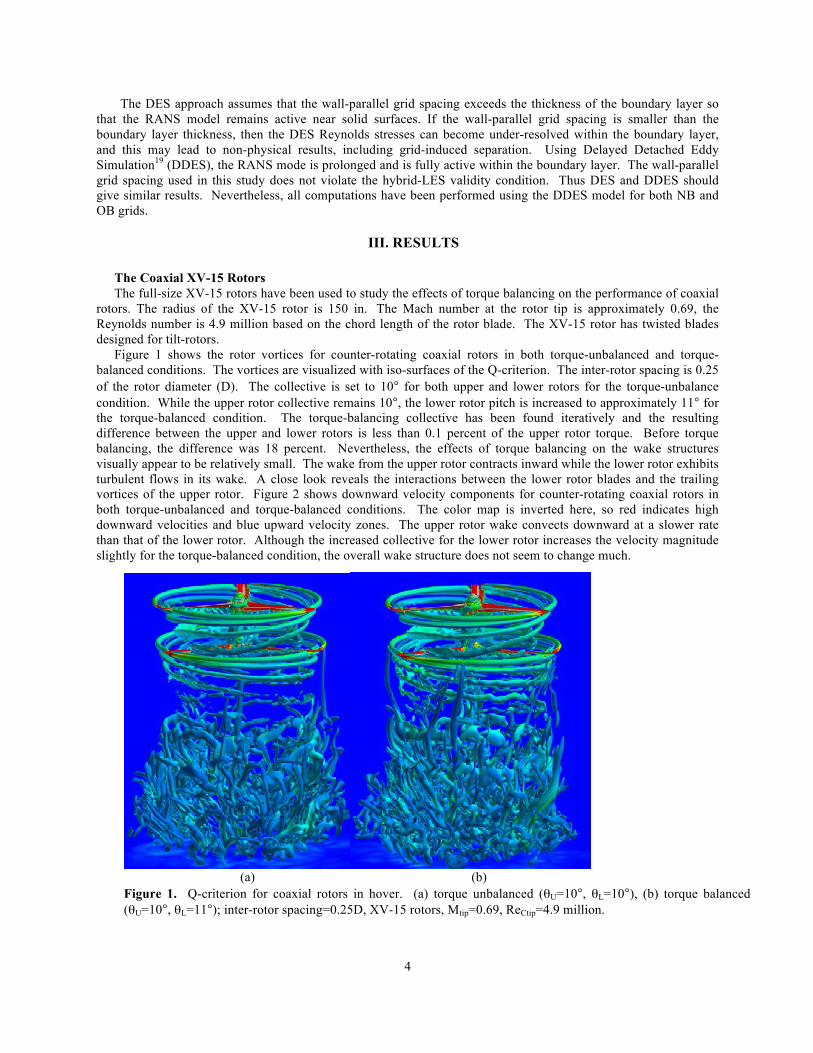
Figure 1 shows the rotor vortices for counter-rotating coaxial rotors in both torque-unbalanced and torque-balanced conditions. The vortices are visualized with iso-surfaces of the Q-criterion. The inter-rotor spacing is 0.25 of the rotor diameter (D). The collective is set to 10° for both upper and lower rotors for the torque-unbalance condition. While the upper rotor collective remains 10°, the lower rotor pitch is increased to approximately 11° for the torque-balanced condition. The torque-balancing collective has been found iteratively and the resulting difference between the upper and lower rotors is less than 0.1 percent of the upper rotor torque. Before torque balancing, the difference was 18 percent. Nevertheless, the effects of torque balancing on the wake structures visually appear to be relatively small. The wake from the upper rotor contracts inward while the lower rotor exhibits turbulent flows in its wake. A close look reveals the interactions between the lower rotor blades and the trailing vortices of the upper rotor. Figure 2 shows downward velocity components for counter-rotating coaxial rotors in both torque-unbalanced and torque-balanced conditions. The color map is inverted here, so red indicates high downward velocities and blue upward velocity zones. The upper rotor wake convects downward at a slower rate than that of the lower rotor. Although the increased collective for the lower rotor increases the velocity magnitude slightly for the torque-balanced condition, the overall wake structure does not seem to change much.
(a) (b) Figure 1. Q-criterion for coaxial rotors in hover. (a) torque unbalanced (θU=10°, θL=10°), (b) torque balanced (θU=10°, θL=11°); inter-rotor spacing=0.25D, XV-15 rotors, Mtip=0.69, ReCtip=4.9 million.

5
Figure 3 shows the effect of inter-rotor spacing on thrust efficiency of coaxial rotors in hover when torques are
not balanced. The overall thrust increases as the inter-rotor spacing decreases. It is interesting to note that the rate of increase in the lower rotor thrust is higher than the rate of decrease in the upper rotor thrust as the inter-rotor spacing decreases.
Figure 4 shows the effect of inter-rotor spacing on thrust efficiency of coaxial rotors in hover when torques are
balanced. While the collective for the upper rotor is fixed, the torque-balancing pitch for the lower rotor has been found using an iterative approach. A comparison of the overall thrust in Fig. 5 shows that the torque-balanced thrust changes little until the inter-rotor spacing decreases to less than 0.25D. The rate of increase in the lower rotor thrust is still higher than the rate of decrease in the upper rotor thrust. The correlation results20 for full-scale and model-scale coaxial rotors also show that more thrust is lost from the lower rotor than the upper rotor when configured coaxially, as compared to single rotors. Though an unbalanced torque produces vortex wakes that look similar to torque-balanced, the two have different quantitative trends.
Figure 3. Effect of inter-rotor spacing on thrust efficiency of coaxial rotors in hover (torque unbalanced). Note: Each rotor’s thrust has been normalized by that of an isolated rotor. The thrust for coaxial rotors is not the total but an average thrust of upper and lower rotors. XV-15 rotors, Mtip=0.69, ReCtip=4.9 million, θU=10°, θL=10°.
(a) (b) Figure 2. Downward velocity components for coaxial rotors in hover. (a) torque unbalanced (θU=10°, θL=10°), (b) torque balanced (θU=10°, θL=11°); inter-rotor spacing=0.25D, XV-15 rotors, Mtip=0.69, ReCtip=4.9 million.

6
Figure 5. A comparison of thrust efficiency for torque-unbalanced and torque-balanced coaxial rotors in hover. Each rotor’s thrust has been normalized by that of an isolated rotor. The thrust for coaxial rotors is not the total but an average thrust of upper and lower rotors. XV-15 rotors, Mtip=0.69, ReCtip=4.9 million, θU=10°, θL=various.
Figure 4. Effect of inter-rotor spacing on thrust efficiency of coaxial rotors in hover (torque balanced). Note: Each rotor’s thrust has been normalized by that of an isolated rotor. The thrust for coaxial rotors is not the total but an average thrust of upper and lower rotors. XV-15 rotors, Mtip=0.69, ReCtip=4.9 million, θU=10°, θL=various.

7
Ramasamy’s Experiment Since Coleman1 reviewed the status of coaxial rotor research in 1997 using various available experiments and
simulations, very few experiments were done on coaxial rotors until Ramasamy7 conducted high-fidelity measurements at various axial separation distances to ascertain the threshold separation distance where performance gains begin to diminish. The test matrix included measurements on highly-twisted XV-15 like blades. The effect of separation distance and overall system thrust on coaxial rotor performance were studied. The present study focused on the XV-15 like blade, which was 1/7 scale of the full-scale version that was elongated by 1 inch at the tip with a constant twist angle. In addition, there is a large root cutout (gap) between the hub and the blade root. As a result, the radius of the experimental rotor (25.872 inch) is approximately 4.44 inch longer than the 1/7 scale of the XV-15 rotor. Although the XV-15 rotor blade is highly twisted, the elongated section has no more twist. Figure 6a shows a view of the experimental setup and Fig. 6b shows a grid system for a simplified computational model blade. It should be noted that the experimental rig and the computational model are not identical because no attempt has been made to model the detailed geometries of the complex hub, the connecting rod, and other small support pieces.
In the experiment, baseline single rotor measurements were made first. This modified XV-15 rotor was used in a previous experiment.21 Both thrust and power were measured by changing the collective pitch in a series of discrete steps at 800 and 1200 rpm, while changing the number of blades from 2 to 4 for twisted blades. In the present study, computations have been performed for a 3-blade rotor at 800 rpm using 70 million grid points. The Reynolds and the tip Mach numbers are 183333 and 0.1667 respectively.
Wake structures depicted by Q-criterion and vorticity magnitude for the 3-bade rotor at 8 deg collective pitch in Fig. 7a show that the vortices formed from the blade root are stronger than those from the blade tip. This unusual phenomenon might be due to a large gap between the hub and the blade root as well as the elongation of the blade near the tip with a constant twist angle. Downward velocity components in Fig. 7b show that velocities are higher inboard than outboard. Inflow being higher near the root was also observed in the measurements.22
Torque vs. Thrust in Fig. 8a and FM vs. Thrust in Fig. 8b show a very good correlation between the numerical solutions and the experimental data except at the high thrust conditions. The pitch angles in the computations have been increased from 0 deg to 12 deg with a 2 deg interval.
Figure 9a shows the flow fields for a coaxial rotor system with an inter-rotor spacing (IRS) of 0.75 diameter (D) of the rotor using 120 million grid points. Even at this fairly large spacing between two rotors, it is seen that the strong vortices from the upper rotor affect the inflow to the lower rotor. A comparison of thrust ratios (TL/TU) for various IRS in Fig. 9b shows a reasonably good correlation with the experimental measurements considering the inherently unsteady nature of the flow interactions and incomplete modeling of the experimental setup.
(a) (b) Figure 6. Modeling the experiment. (a) Ramasamy’s experimental setup, (b) a simplified computational model

8
(a) (b) Figure 7. Flow fields of the experimental rotor (1/7 scaled and elongated XV-15 rotor). (a) Q-criterion, (b) downward velocity, Mtip=0.1667, ReCtip=183333, θ=8°.
(a) (b) Figure 8. Simulations of the experimental rotor (1/7 scaled and elongated XV-15 rotor). (a) Torque vs. Thrust, (b) FM vs. Thrust, Mtip=0.1667, ReCtip=183333, θ = 0°-12°.

9
Coaxial Quadcopter Vehicle The use of multiple rotors provides redundancy as well as cost-efficiency. One of the most popular multi-rotor
configurations is a quadrotor. Although the first quadrotor was built more than a hundred years ago, the concept has rarely been used until recently because of its inherent stability and control problems. However, recent advances in inexpensive electronic flight control systems have opened the floodgates for multi-rotor drones. The DJI Phantom models are very popular consumer vehicles and have the largest market share in the world. The geometric data have been extracted from a high-resolution laser scan of the blade surfaces. The DJI Phantom carbon fiber rotor has a radius of 0.12m and a chord of 0.01m near the tip. At 5400 rpm, the Reynolds and the tip Mach numbers are 45971 and 0.198 respectively. The carbon fiber rotor used here is not the same as the factory Phantom 3 plastic blades.
In order to study the effect of coaxial rotors on the performance of a quadcopter, the configuration has been modified by the addition of four rotors beneath the fuselage. The resulting vehicle configuration employs eight rotors and fuselage. The total number of grid points for the vehicle system is 250 million.
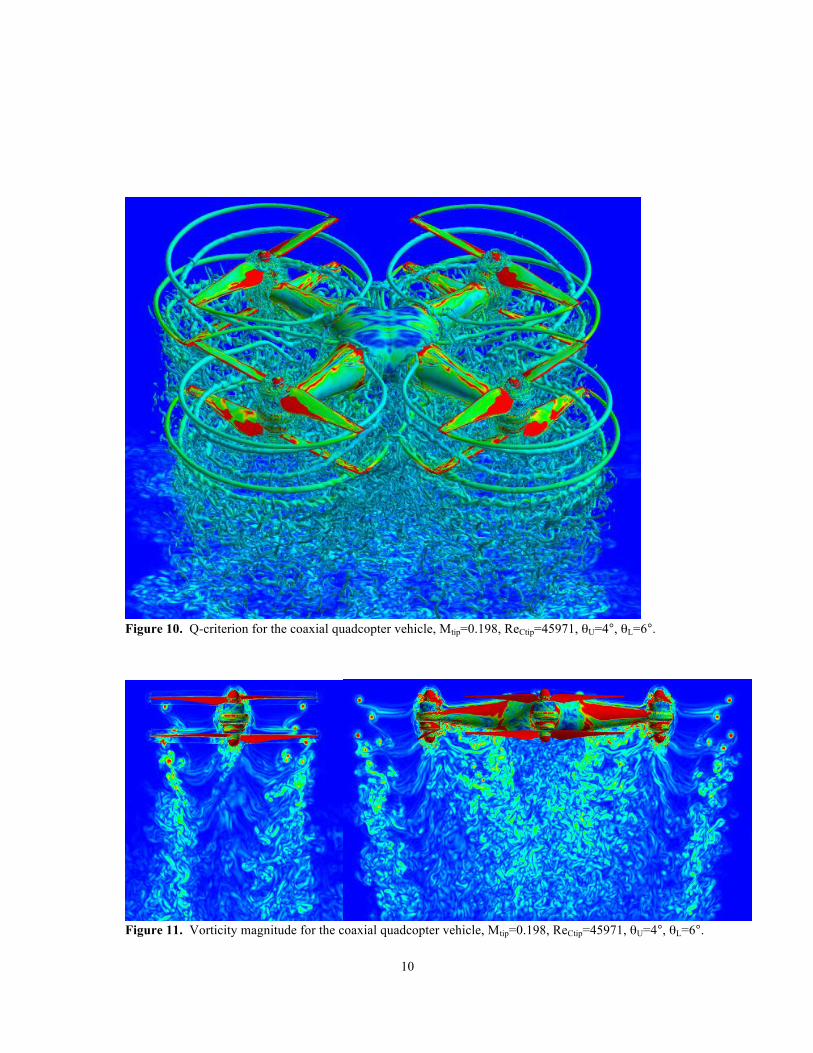
Figure 10 shows Q-criterion for a torque-balanced coaxial rotor system. The pitch angle for the upper rotors is 4 deg. The collective pitch for the lower rotor is set to be approximately 2 deg higher than that for the upper rotor to minimize the net torque. Note complex interactions between rotors as well as between rotors and fuselage. Although not included here, a flow simulation movie shows blade-vortex interactions too. When the upper rotor blades pass over the arms, high pressure on the fuselage surface creates a download force. The lower rotors also contribute to a download by pulling the air from above albeit with a smaller magnitude than the upper rotors. Although not included here, rotor blades placed not in phase create an asymmetrical pressure distribution on the fuselage and result in a thrust oscillation and a dynamic instability.
Figures 11 and 12 show vorticity and velocity magnitudes respectively for both a single coaxial rotor system and the coaxial quadrotor vehicle. Although rotors are placed at the end of the arms, interactions between rotors and fuselage create a low-speed zone below the fuselage. Interactions between tip vortices and fuselage appear to diffuse the inboard vortices. Nonetheless, outboard tip vortices from the upper rotors seem to be preserved inside the wake of the lower rotors until they interact with the lower rotor vortices. It is interesting to note that the whole vehicle wake contracts like a large single rotor.
(a) (b) Figure 9. Effect of inter-rotor spacing on the thrust ratio of the experimental coaxial rotor (1/7 scaled and elongated XV-15 rotor). (a) Q-criterion for IRS=0.75D, (b) Thrust Ratio (TL/TU) vs. IRS, Mtip=0.1667, ReCtip=183333, θU=7.8°, θL=various.
10
Figure 11. Vorticity magnitude for the coaxial quadcopter vehicle, Mtip=0.198, ReCtip=45971, θU=4°, θL=6°.
Figure 10. Q-criterion for the coaxial quadcopter vehicle, Mtip=0.198, ReCtip=45971, θU=4°, θL=6°.

11
Vertical forces for various multi-rotor configurations are compared in Table 1. An isolated single rotor with two
carbon fiber blades generates approximately 3.2N of thrust at 5400 rpm and 4 deg pitch. The computed thrust at 0 deg pitch has been validated against the experimental measurements for the identical rotor.23 Forces in the table have been normalized by four times the single rotor thrust. The computed total thrust for a quadcopter is 12.15N. This number compares well to the experimental data24 for the baseline configuration considering the factory blade used in the experiment produces a higher thrust. It is interesting to note that four rotors of the quadcopter generate a slightly higher thrust than the sum of four single rotors possibly because the fuselage creates a ground effect. However, a download created by the fuselage reduces the total thrust by 7.4 percent. The addition of four more rotors beneath the fuselage without balancing the torque increases the total thrust of the quadcopter by 66 percent. Torque balancing increases the total thrust of the coaxial quadcopter by 9.5 percent. Hence, the torque-balanced coaxial quadrotor vehicle generates an 82 percent higher thrust than a quadcopter.
Configuration Rotor Thrust Fuselage Download Total Thrust Quadcopter 1.0250 -0.0758 0.9492 Coaxial Quadcopter (torque unbalanced) 1.7203 -0.1422 1.5781 Coaxial Quadcopter (torque balanced) 1.8828 -0.1539 1.7289
Table 1. Total thrust for various multi-rotor configurations (Forces have been normalized by 4x an isolated single rotor thrust.)
SUMMARY The effects of torque balancing on the performance of coaxial rotor systems have been studied. Since torque
balancing improves relative performance of the lower rotor, the average thrust of the torque-balanced coaxial XV-15 rotors changes little until the inter-rotor spacing decreases to less than a quarter of the rotor diameter. The rate of increase in the lower rotor thrust is still higher than the rate of decrease in the upper rotor thrust albeit slower than in the torque unbalanced condition. Comparisons of computational solutions with the experimental data for a modified XV-15 rotor show a good correlation. Torque-balanced coaxial rotor systems can increase the total thrust of a quadcopter vehicle significantly.
ACKNOWLEDGMENTS This work was supported by the RVLT and DELIVER projects. Mani Ramasamy provided the information on
the model rotor blade geometry and his experimental data. Patricia Ventura Diaz generated overset grids for the coaxial quadcopter vehicle. The first author thanks Gloria Yamauchi, Henry Lee, Neal Chaderjian, and Nagi N. Mansour for providing valuable reference materials and helpful discussions.
Figure 12. Velocity magnitude for the coaxial quadcopter vehicle, Mtip=0.198, ReCtip=45971, θU=4°, θL=6°.

12
REFERENCES
1Coleman, C. P., “A Survey of Theoretical and Experimental Coaxial Rotor Aerodynamic Research,” NASA TP 3675, NASA Ames Research Center, 1997.
2Leishman, J. G. and Ananthan, S., “Aerodynamic Optimization of a Coaxial Proprotor,” The 62nd AHS Annual Forum, May 2006.
3Syal, M. and Leishman, J. G., “Aerodynamic Optimization Study of a Coaxial Rotor in Hovering Flight,” Journal of the American Helicopter Society, 57, 042003, 2012.
4Barbely, N. L., Komerath, N. M., and Novak, L. A., “A Study of Coaxial Rotor Performance and Flow Field Characteristics,” The AHS Technical Meeting on Aeromechanics Design for Vertical Lift, San Francisco, California, Jan. 2016..
5Lakshminarayan, V. K. and Baeder, J. D., “High-Resolution Computational Investigation of Trimmed Coaxial Rotor Aerodynamics in Hover,” Journal of the American Helicopter Society, 54, 042008, 2009.
6Yoon, S., Lee, H. C., and Pulliam, T. H., “Computational Study of Flow Interactions in Coaxial Rotors,” The AHS Technical Meeting on Aeromechanics Design for Vertical Lift, San Francisco, California, Jan. 2016.
7Ramasamy, M., “Hover Performance Measurements Toward Understanding Aerodynamic Interference in Coaxial, Tandem, and Tilt Rotors,” Journal of the American Helicopter Society, 60, 032005, 2015.
8Yoon, S., Pulliam, T. H., and Chaderjian, N. M., “Simulations of XV-15 Rotor Flows in Hover Using OVERFLOW,” The 5th Decennial AHS Aeromechanics Specialists’ Conference, San Francisco, California, Jan. 2014.
9Chan, W. M., “The OVERGRID Interface for Computational Simulations on Overset Grids,” AIAA Paper 2002-3188, St. Louis, Missouri, June 2002.
10Chan, W. M., “Developments in Strategies and Software Tools for Overset Structured Grid Generation and Connectivity,” AIAA Paper 2011-3051, Honolulu, Hawaii, June 2011.
11Pulliam, T. H., “High Order Accurate Finite-Difference Methods: as seen in OVERFLOW,” AIAA Paper 2011-3851, June 2011.
12Nichols, R., Tramel, R., and Buning, P., “Solver and Turbulence Model Upgrades to OVERFLOW2 for Unsteady and High-Speed Flow Applications,” AIAA Paper 2006-2824, June 2006.
13Yoon, S., Chaderjian, N. M., Pulliam, T. H., and Holst, T. L., “Effect of Turbulence Modeling on Hovering Rotor Flows,” AIAA Paper 2015-2766, The 45th AIAA Fluid Dynamics Conference, Dallas, Texas, June 2015.
14Yoon, S., Lee, H. C., and Pulliam, T. H., “Computational Analysis of Multi-Rotor Flows,” The 54th AIAA Aerospace Sciences Meeting, San Diego, CA, Jan. 2016.
15Jespersen, D., Pulliam, T. H., and Buning, P., “Recent Enhancements to OVERFLOW,” AIAA Paper 97-0644, Reno, Nevada, Jan. 1997.
16Lakshminarayan, V. K. and Baeder, J. D., “Computational Investigation of Micro Hovering Rotor Aerodynamics,” Journal of the American Helicopter Society, 55, 022001, 2010.
17Spalart, P. R., W-H. Jou, Strelets, M., and Allmaras, S. R., “Comments on the Feasibility of LES for Wings and on a Hybrid RANS/LES Approach,” Advances in DNS/LES, Greyden Press, 1997, pp. 137-147.
18Spalart, P. R. and Allmaras, S. R., “A One-Equation Turbulence Model for Aerodynamic Flows,” AIAA Paper 1992-0439, Jan. 1992.
19Spalart, P. R., “Strategies for Turbulence Modeling and Simulations,” International Journal of Heat and Fluid Flow, 21, 2000, pp. 252-263.
20Lim, J. W., McAlister, K. W., and Johnson, W., “Hover Performance Correlation for Full-Scale and Model-Scale Coaxial Rotors,” Journal of the American Helicopter Society, 54, 032005, 2009.
21McAlister, K. W., Tung, C., Rand, O., Khromov, V., and Wilson, J. S., “Experimental and Numerical Study of a Model Coaxial Rotor,” The 62nd AHS Annual Forum, Phoenix, Arizona, May 2006.
22Ramasamy, M., Gold, N. P., and Bhagwat, M. J., “Flowfield Measurements to Understand Effects of Wake Behavior on Rotor Performance,” AIAA Paper 2010-4237, The 28th AIAA Applied Aerodynamics Conference, Chicago, IL, July 2010.
23Zawodny, N. S., Boyd, D. D., and Burley, C. L., “Acoustic Characterization and Prediction of Representative, Small-Scale Rotary-Wing Unmanned Aircraft System Components,” The 72nd AHS Annual Forum, West Palm Beach, Florida, May 2016.
24Russell, C., Jung, J., Willink, G., and Glasner, B., “Wind Tunnel and Hover Performance Test Results for Multicopter UAS Vehicles,” The 72nd AHS Annual Forum, West Palm Beach, Florida, May 2016.