air conditioning & heat pump products technical training · pdf fileair conditioning &...
TRANSCRIPT

Air Conditioning & Heat Pump Products
Technical Training
Single Mini Split 9,000-24,000 Btu
Flexi-Multi 19,000-31,000 Btu
Single Mini Split 26,000-42,000 Btu

1
Table of contents Page
1) Dealer training & certification………………………………………………….2-3
2) Sanyo technical contact information…………………………………………....4
3) Product Line-up model & serial number identification…………………….…5-9
4) (RAC) Product line-up, 9,000-24,000 Btu, single minis & flexi multi ……….10-13
5) Installation clearances…………………………………………………………..14-16
6) Condensate pumps………………………………………………………………17-22
7) Tubing size, length, elevation, insulation and refrigerant charge……………23-24
8) Wiring 9,000-24,000 Btu & flexi multi……………………………………..….25-32
9) Wireless, wired remote controls, address setting & basic functions………...33-39
10) Troubleshooting 9,000-24,000 Btu & flexi multi…………………………....40-60
11) Step-by-step troubleshooting procedure 9,000-24,000 Btu & flexi multi….60-63
12) (PAC) Product line-up 26,000-42,000 Btu systems ………………………....64-70
13) Operation range 26,000-24,000 Btu, tubing, length, refrigerant charge…..71-72
14) Wiring 26,000-42,000 Btu…………………………………………………….73-74
15) Remote control line-up……………………………………………………….75-76
16) Troubleshooting with the RCS-TM80BG remote controller………………77-80
17) Wireless remote controller…………………………………………………...81
18) Troubleshooting 26,000-42,000 Btu…………………………………………82-88
19) Error code details 26,000-42,000 Btu………………………………………..89-101
20) EPROM chip and replacing an indoor or outdoor circuit board………....102-106
21) Performance data 9,000-24,000 Btu pressure / temperature charts………107-120
2
WWW.US.SANYO/HVAC.COM
Sanyo offers a wide variety of Technical Service Training
Hands-On Service Training (Kennesaw Facility): Come to our Georgia facility and train on live ECO-i & Mini-Split equipment On-Demand Videos train at your leisure: ECO-i installation & commissioning Troubleshooting the 3 way solenoid ECO-i maintenance controller ECO-i service (3 parts) Mini split installation & service How to display room temperature on a wired remote controller Dismantling the “K” wall mounted unit. PAC installation & service Installing a STK-RCS-7TWSUA wired remote controller
Webinar Classes: How to use the RCS-TM80BG as a service tool. Mini Split & Flexi Multi Installation ECO-i Installation ECO-i Commissioning EC0-i Service
Online Dealer Certification Courses: ECO-i installation, Commissioning & Service Mini Split & Flexi Multi Installation & Service
You will be required to take and pass an on-line test after the class to become a Sanyo Dealer

3
WWW.US.SANYO/HVAC.COM
SANYO Dealer Network: Certification on Demand
On our website main page click on the training tab then the Online Dealer Certification Courses tab
SANYO now offers comprehensive training classes all on-line, that can be taken at your own pace. By successfully completing the 3 consecutive courses, you can become a certified gold, silver or bronze SANYO HVAC dealer.
ECO-i Installation Course:
This training course focuses on Sanyo’s ECO-i Multi Split Variable Flow Refrigerant (VRF) system. Upon completion of this course participants should have attained the required skills to properly configure and install the ECO-i system.
ECO-i Commissioning: This training course focuses on Sanyo’s ECO-i Multi Split Variable Flow Refrigerant (VRF) system. Upon completion of this course participants should have attained the required skills to properly configure and commission the ECO-i system.
ECO-i Service:
This training course focuses on Sanyo’s ECO-i Multi Split Variable Flow Refrigerant (VRF) system. Upon completion of this course participants should have attained the required skills to properly configure a system, install the system, commission the system and to conduct in depth service, troubleshooting and diagnostics.
Mini Split and Flexi Multi Installation & Service:
This training course provides the participants with an overview of Sanyo’s R-410a one-to-one split and Flexi Multi products including installation requirements, unit specifications, operating characteristics and a detailed review of service and troubleshooting procedures.
Mini Spilt Models 26-4272R:
This training course provides the participants with an overview of Sanyo’s R-410a one-to-one Pac (26K - 42K BTU) products including installation requirements, commissioning procedures, operating characteristics and a detailed review of service and troubleshooting procedures.

4
SANYO HVAC CONTACT INFO
TECHNICAL SUPPORT:
WEBSITE:
WWW.US.SANYO/HVAC.COM
NOTE: Service, installation, user guides and submittals can be obtained through our website.

5
Product Overview:
Sanyo’s product line offers environmentally friendly 0 ozone depletion potential, R410a refrigerant.
All models meet and exceed Federal DOE guidelines for energy efficiency, 13+S.E.E.R
Caution for Installation:
Higher Pressure ( R410a is 1.6 times higher than R22.) Compressor oil is different. R410a uses Polyvinyl Ether Oil (Synthetic fluid) Different gauge-manifold, charge hose, etc., must be used for R410a. Near-Azeotrope Type Refrigerant Only charge the refrigerant in liquid form. New refrigerant piping is required for all R410a installs.
5/16” Service Ports:
Service ports are different then on R22 systems. Sanyo R410a systems have 5/16” male flare fittings. Adaptor must be used when using 1/4” hoses. These adaptors (5/16” ffl x 1/4” mfl) are available from the following manufacturers: Ritchie Part Number 19173 Ritchie Part Number 93825(Ball Valve) JB Industries Part Number QC-S5

6
What is an Inverter Air Conditioner?
Unlike a standard air conditioner which uses a constant fixed speed compressor, the DC inverter controlled compressor will always start at it’s minimum revolutions and slowly speed up to meet current system demand. This greatly reduces the power surge needed at start up.
This is obtained by converting incoming AC power to DC power, thereby making it possible to accurately control the systems capacity. When the maximum capacity is not required, the compressor revolution is decreased.
This means the power decreases too, which results in increased system efficiency with reduced operating electrical costs.
Variable speed inverter driven compressors provide a range of capacities
and are listed with minimal, nominal and maximum capacities
The compressor starts at a minimum frequency of 23% of maximum capacity
Allows for low superheat of 0-5 degrees
Allows for greater utilization of the evaporator The Sanyo Inverter is a true DC compressor

7
Model Number by System:
Model Number by Component:
System:18KHS72
18 K H S 7 2
Cooling Capacity in BTU/h
Indoor Unit TypeK: Wall MountedT: Ceiling SuspendedX: 4way Ceiling RecessedU: Concealed Duct
M: Multi-Zone
Voltage: 1-115v2-208/230
Model Series No.
S: wireless remote ControlW: wired Remote ControlH: Heater
FunctionH: Heat PumpL: Low Ambient
Component:KHS1872 / CH1872K H S 1 8 7 2
Voltage1-115v2-208/230v
Model Series No.
Cooling CapacityIn BTU/h
S: Wireless remoteW: Wired remoteH: Heater
FunctionH: Heat Pump
Indoor Unit TypeK: Wall MountT: Ceiling SuspendedX: 4way Ceiling RecessedU: Concealed DuctC: Outdoor Unit
M: Multi-Zone
Indoor Unit Outdoor Unit

8
Serial number Identification:
Warranty Policy:
After September 1, 2009: Standard warranty on Single Split and Flexi-Multi Systems is 7 years compressor & 5 years functional parts. The new extended warranty is in effect for Sanyo ducted and ductless split system installed on or after Sept 1 2009 Before September 1, 2009: All R22, ECOI, Single and Flexi-Multi Systems split models installed before Sept 1 2009 remain 6 years compressor & 1 year on functional parts.
0 7 1 6 3
Consecutive Sequence Number
Year of Manufacture
Quarter of Year: 1: Jan - Mar 2: Apr - Jun 3: Jul - Sep 4: Oct - Dec
3 0 7 5 3 6 0 0

9
Certifications http://www.ahridirectory.org
Sanyo Products meet or exceed all major regulating agencies equipment standards of performance and compliance.

10
Wireless Remote Control (Standard)
Wired Remote Control (Optional)
Wireless Remote Control
(Standard)
STK-RCS-7TWSU Wired Remote Control
(Optional)
STK-KCW1 Wiring Harness
12KHS71
12KLS71
12KS71
12,000 BTU
17 SEER
09KHS71
09KLS71
09KS71
9,000 BTU
16 SEER
24,000 BTU
17 SEER
18,000 BTU
20 SEER
Type
Heat Pump Cooling &
Heating to 0 Deg f
Single Cooling *Low ambient
cooling to 0 deg f
Single Cooling *Cooling to
50 deg f
24KHS72
18KHS72
24KLS72
18KLS72
24KS72
18KS72
18XHS71
18XLS71
18XS71
18,000 BTU
20 SEER
12XHS71
12XLS71
12XS71
12,000 BTU
17 SEER
Type
Heat Pump Cooling &
Heating to 0 Deg f
Single Cooling Low ambient
Cooling to 0 Deg f
Single Cooling *Cooling to
50 deg f
K Series Wall Mounted
X Series Ceiling recessed
RAC Product Lineup: R410a, Single Zone, Inverter (16-20 SEER)

11
Wireless Remote Control (Standard) Wired Remote Control (Optional)
KMHS0972
KMS0972
9,000BTU
Heat Pump
Cooling Only
Type
KMHS2472 KMHS1872 KMHS1272 KMHS0772
KMS2472 KMS1872 KMS1272 KMS0772
24,000BTU 18,000BTU 12,000BTU 7,000BTU K Series Wall Mounted
Flexi Multi Product Lineup:R410a, Multi Zone, Inverter, (14.8-16.8 SEER)
XMHS1272
XMS1272
12,000BTU
Heat Pump
Cooling Only
Type
XMHS1872 XMHS0972
XMS1872 XMS0972
18,000BTU 9,000BTU X Series Ceiling Recessed
CM3172 CM2472 CM1972 Cooling Only
CMH2472
CLM2472
24,000BTU
Heat Pump
Cooling Low Ambient
Type
CMH3172 CMH1972
CLM3172 CLM1972
31,000BTU 19,000BTU
Outdoor Units
Minimum of Two Indoor Units Required
Wireless Remote Control
(Standard)
STK-RCS-7TWSU Wired Remote Control
(Optional)
STK-KCW1 Wiring Harness

12
Negative Ion Generator
While operating, this unit generates negative ions that freshen up the conditioned space.
Enlarged View of the ION Generator (Can Be Disabled)

13
Operating Range 9,000-24,000 BTU Single Mini Splits
All RAC systems stop operating in temperatures below Cut-Off –Temperature. Operation below Operating Range is out of warranty. *3 No maximum temperature cut-out.
Operating Range for the Flexi-Multi Series
M in . M a x . M in . M a x .
-4 D B
6 7 D B
*1
0 F D B
N /A
7 5 F D B 6 5 F W B
-8 D B *4
*2
N /A N /A N /A
5 5 F D B
N /A
C L M 3 1 7 2
C M 2 4 7 2
C M 3 1 7 2
C L M 1 9 7 2
C L M 2 4 7 2
C M H 1 9 7 2
C M H 2 4 7 2
C M H 3 1 7 2
C M 1 9 7 2
O p e ra t in g R a n g e L im its B a s e d O n O u td o o r T e m p e ra tu re ( D e g re e s F )
D e s ig n O u td o o r O p e ra t in g R a n g e C o o lin g C u t-O ff H e a t in g C u t-O f f
M a x . O u td o o r
M o d e l C o o lin g H e a t in g M in .
O u td o o r M a x .
O u td o o r M in .
O u td o o r
*1: 32F DB: Combined with KMS1872 and/or KMS2472 / 23F DB: When combined only with KMS0772, KMS0972 and/or KMS1272. *2: 28F DB: Combined with KMS1872 and/or KMS2472 19F DB: When combined only with KMS0772, KMS0972 and/or KMS1272. *4: No maximum temperature cut-out
Min. Max. Min. Max.
N/A N/A -4 DB
-4 DB
-8 DB
-13 DB
50 DB
-8 DB 122F DB0F DB
50 DB 115F DB *3
N/A N/A
75F DB 65F WB
-4 DB
0F DB
0F DB
CL0971
CL1271
CL1872
CL2472
C0971
C1271
C1872
C2472
CH0971
CH1271
CH1872
CH2472
Operating Range Limits Based On Outdoor Temperature ( Degrees F )
Design Outdoor Operating Range Cooling Cut-Off Heating Cut-Off
Max. Outdoor
Model Cooling Heating Min.
Outdoor Max.
Outdoor Min.
Outdoor

14
Basic System Layout
¾” PVC adaptor provided for the condensate drain Wireless remote control (Standard) Wired remote control (Optional)
Return Air
Supply Air Drain
Narrow Pipe
Wide Pipe

15
Indoor Unit Site Selection (“K” Series Wall Mounted)
Ceiling
Floor
Note
Note Note
Bottom of indoor unit to the finished floor. (5 foot minimum)
Wall
Installation clearances vary depending on the size and model of the unit being installed. Always refer to the installation manual for proper unit clearances.

16
Site Selection (Outdoor Unit)
(Minimum Clearances Shown)
Always leave room for service and cleaning when selecting the installation site.
Dischargemin. 16”
Intake min. 2”
Valve side
min. 10”
Intake min. 2”
Above min. 7ft

17
Condensate Pump (Installation and Wiring)
Example of the Sauermann 3100 Series
The above condensate pump is an after market item. Sanyo does not manufacture or warranty these items. The installer may choose the pump of his/her personal choice.

18
Mounting the Receiver (Float Safety Switch)
First place the self-adhesive support that holds the detection unit
Attach the condensate hose before mounting the self-adhesive support to insure proper location and attach the supplied air bleeder hose
Bleeder Hose
Attach Bleeder Hose Here

19
Mounting the Condensate Pump
Keep into account the maximum distance between the pump and the detection unit (vertical suction-head) refer to installation manual. Clear tubing available as an optional accessory. (Inner diameter 0.24”)

20
Condensate Wiring for RAC 9,000-24,000 BTU
Land the power wires from the pump to terminals 1 & 2 on the indoor unit.
Break line 3 on the indoor unit for the safety switch wiring.
Sauermann Condensate Pump Wiring Instructions This diagram is for the following Sanyo Indoor Unit Models: KMS0772, KMHS0772, KMS0972, KMHS0972, KMS1272, KMHS1272, KS1872, KHS1872, KMS1872, KMHS1872, KS2472, KHS2472, KMS2472 & KMHS2472 (Please note all the above Sanyo models operate off of 208/230 VAC 60Hz) Diagram is shown utilizing a Sauermann SI-3100-2 or SI-1730-2 Condensate Pump
1 2 3 G
Power Supply 208/230 VAC 60 Hz Sanyo Indoor Unit’s Terminal Strip
Power Supply 208/230 VAC 60 Hz Sanyo Outdoor Unit’s Terminal Strip
1 2 3 4
Sauermann Pump Model SI-3100-2 & SI-1730-2 (208/230 VAC 60 Hz)
5 6 G
L1 L2 G C NC630 mA Fuse
Power Supply Outdoor Unit 208/230 VAC 60 Hz
Pump Wire Colors for SI-3100-2 Power Wiring: Brown Wire = L1 Blue Wire = L2 Green Wire = Ground Alarm Circuit Wires: Yellow Wire = C White Wire = N/C

21
Condensate wiring for a PAC product (26,000-42,000 BTU)
Cut the CN09 connector and wire the safety through this
connection on the indoor circuit board.
Sauermann Condensate Pump Wiring Instructions This diagram is for the following Sanyo Indoor Unit Models: KHS2672R, KHHS2672R, KHS3072R, KHS3672R, THW2672R, THHW2672R, THW3672R, THHW3672R, THW4272R, XHW2672R, XHW3672R, XHW4272R, UHW2672R & UHW3672R (Please note all the above Sanyo models operate off of 208/230 VAC 60Hz) Diagram is shown utilizing a Sauermann SI-3100-2 or SI-1730-2 Condensate Pump
1 2 G
Power Supply 208/230 VAC 60 Hz Sanyo Indoor Unit’s Terminal Strip
Sauermann Pump Model SI-3100-2 & SI-1730-2 (208/230 VAC 60 Hz)
L1 L2 G C NC630 mA Fuse
Float Switch Jumper (CN09) Red Connector Located on Indoor Unit’s PCB
Note: The X & U style indoor units have a primary float switch installed from the factory. When adding an additional aux. pump, wire the aux. pumps N/C contacts in series with the indoor unit’s factory installed float switch.
Pump Wire Colors for SI-3100-2 Power Wiring: Brown Wire = L1 Blue Wire = L2 Green Wire = Ground Alarm Circuit Wires: Yellow Wire = C White Wire = N/C
CN09 Red Connector
Indoor PCB Board

22
The Following Models are Equipped With Built in Drain Pumps
• XHX models: Four Way Supply Ceiling Recessed
• UHX models: Concealed Duct ( Low Static Models)
• All of the above models have built in float switches
Connect Drain Line Here
Pan Inspection Port
These pumps have a limited vertical lift as shown

23
RAC 9,000-24,000 Btu Flexi-Multi 19,000-31,000 Btu
Tubing, Sizes, & Elevation Difference Refrigerant Charge Adjustment & Insulation Chart

24
Tubing Limitations: (Flexi-Multi Systems)
0.22 Oz. / ft.200 (L1+ L2+ L3+L4)
50
50
50
Required Amount of Additional
Refrigerant (Oz. / ft.
82
82
150 (L1+L2+L3)
150 (L1+L2+L3+L4)
150 (L1+L2+L3)
200 (L1+ L2+ L3+L4)
N/A
0.22 Oz. / ft.
Max. Allowable Total Tubing Length at Shipment Unit Pre-
Charged Length (L1+L2+L3) or (L1+L2+L3+L4) (ft.)
CMH1972
CMH2472
CMH3172
Limit of Elevation Difference
(H1, H2, H3, H4) (ft.)
Outdoor Unit Above
Indoor Unit Above
100 150 (L1+L2+L3+L4)
Model
Max. Allowable
Tubing Length Per Unit
(ft.)
Limit of Total Tubing Length Exceeding Pre-Charged Length
Maximum Piping Length (L1+L2+L3) or (L1+L2+L3+L4)
(ft.)
50
50
50
Indoor 1 Indoor 2
Indoor 3 Indoor 4
(L1)= Tubing length
(L3)
(L2)
(L4)
(H1) = Elevation Difference
(H3)
(H2)
(H4)
Tubing Length = L1 Elevation Difference = H1

25
Note: The 9,000 & 12,000 BTU models in a single split
combination require a 115 volt power supply.
Installation wiring for 115 volt single split systems.
Disconnect switch is field supplied.
Indoor disconnect not required. Follow local codes.
14 gauge wire minimum
1
2
3
4
5
6
G
Hot
Neutral
Ground
Disconnect Switch (Field Supplied)
Outdoor Unit
Neutral
Hot
12-15 VDC Signal
1
2
3
G G
Indoor Unit 115 VAC (Power Supply)
Disconnect Switch (Field Supplied) Follow Local Electrical Codes
Typical Installation Wiring For: C-CL0971, CH0971, C-CL1271 & CH1271
RAC Single Split System (A/C & HP)

26
Installation wiring for the 230 volt single split systems.
These 230 volt systems are polarity sensitive.
Disconnect switch is field supplied.
Indoor disconnect not required. Follow local codes.
14 gauge wire minimum.
1
2
3
4
5
6
G
L1
L2
Ground
Disconnect Switch (Field Supplied) Follow Local Codes
Outdoor Unit
115V 12-15 VDC Signal
1
2
3
G G
Indoor Unit
115V
208/230 VAC (Single Phase) Power Supply
Disconnect Switch (Field Supplied)
RAC Single Split System (A/C & HP)
Typical Installation Wiring For: C-CL1872, CH1872, C-CL2472 & CH2472

27
Flexi-Multi (Cooling Only & HP)
Installation wiring for the 230 volt multi split systems.
These 230 volt systems are polarity sensitive.
Disconnect switch is field supplied.
Indoor disconnect not required. Follow local codes.
14 gauge wire minimum.
1
2
3
G
1
2
3
G
1
2
3
GG
1
2
3
G
4
5
6
G
7
8
9
“C”
“B”
“A”
Outdoor Unit
1
2
G
L1
L2
Ground
Disconnect Switch Field Supplied
115 V
115 V
12-15 VDC
115 V
115 V
115 V
115 V
12-15 VDC
12-15 VDC
208/230 VAC (Single Phase) Power Supply
Disconnect Switch (Field
Supplied) Follow Local
Electrical
Indoor Unit
Typical Installation Wiring For: CM-CLM-CMH, 1972, 2472, 3172

28
Typical Mis-Wiring (RAC systems 9,000-24,000)
Example: The wires landed on terminals 1 & 2 from the indoor unit to the outdoor unit are crossed.
1. You just completed the installation and powered the system. 2. You turn the indoor unit on with the wireless remote control. 3. The operation light instantly starts blinking.
1
2
3
G
1
2
3
G
The operation light should always be steady on when the unit is running. Blinking means there is a fault.

29
Typical Mis-Wiring (RAC systems 9,000-24,000)
Example: The wire landed on terminal 3 is open or shorted.
Is there a condensate pump installed. If properly installed the safety switch wiring should be landed on terminal three. Determine if the pump has failed
Proper voltage reading at the indoor & outdoor units between terminals 2 & 3 should be 12-15v DC.
1
2
3
G
1
2
3
G
X

30
Typical Mis-Wiring (Flexi-multi systems)
1. Keep track of the wiring for each circuit. A to A, B to B, C to C
2. Keep track of the piping. Piping circuit A to wiring circuit A and so on for all the circuits.
3. This illustration displays the most common wiring / piping mistake made on the Flexi-Multi systems.
G
1
2
3
G
4
5
6
G
7
8
9
“C”
“B”
“A”
1
2
G
L1
L2 Ground
Disconnect Switch Field Supplied
1
2
3
G
1
2
3
G
1
2
3
G
Indoor A
Indoor B
Indoor C
Condensing Unit

31
Flexible Combinations (Systems designed for each job)
New Ceiling mounts available 2010
Ceiling recessed and wall mounts can be mixed and matched
7k
31k
9k 12k
24k
18k
24k 19k
Maximum Connecting Capacity of 130 % Minimum of two indoor units required

32
Distribution Header (CM2472, CLM2472 and CMH2472)
D C B A
Any combination can be used on any circuits A, B, C, or D to a maximum of THREE indoor unit’s total
The 24,000 BTU series is designed for THREE indoor units maximum.
Any of the four ports can be used in any combination
but only Three circuits Maximum. The “1/2 “circuit is for larger BTU indoor units.
CM, CLM, CMH1972= 3 indoor unit’s maximum
CM,CLM,CMH2472= 3 indoor unit’s maximum
CM, CLM, CMH3172= 4 indoor unit’s maximum

33
Wireless Remote Controller
The remote control when in the “ON” state transmits a signal every 5 minutes
The remote control will restart the unit after a power interruption.
It is important to locate the remote in an area where the signal can be received by the indoor unit.
Once a signal is transmitted a “low tone beep” should be heard at the indoor unit.
Once the outdoor unit has been started in heating or cooling there is a 5 minute minimum run time.
There will also be a 3 minute delay on startup of the outdoor unit.
Occasionally lighting can affect the signal.
Maximum Distance From the Indoor Unit is 26 Feet
Ion
Temp Setting
Quiet Fan Speed
Flap
Sensor Addres ACL / Reset
1 Hour Timer
Tem
s
perature Sensor
Mode
12/24 Hour Format
NiNight Setback
On / Off
Hig
33
Wireless Remote Controller
The remote control when in the “ON” state transmits a signal every 5 minutes
The remote control will restart the unit after a power interruption.
It is important to locate the remote in an area where the signal can be received by the indoor unit.
Once a signal is transmitted a “low tone beep” should be heard at the indoor unit.
Once the outdoor unit has been started in heating or cooling there is a 5 minute minimum run time.
There will also be a 3 minute delay on startup of the outdoor unit.
Occasionally lighting can affect the signal.
Maximum Distance From the Indoor Unit is 26 Feet
Ion
Temp Setting
Quiet Fan Speed
Flap
Sensor Address ACL / Reset
1 Hour Timer
Temperature Sensor
Mode
12/24 Hour Format
ght Setback
On / Off
High Power
Timer Setup

34
Occasionally lighting can affect the signal.
Change the batteries to the remote every 6 months. Press the ACL button when new batteries are installed
Page 4 of the installation manual states:
Install the indoor unit more than 1 meter (3.3’) away from electronic devices such as televisions, radios, telephones, etc.
Electrical noise from these may affect operation.

35
Wired Remote Controller
The STK-KCW1 Wiring harness is necessary to convert a “K” model from wireless to a wired remote control. The “X” series ceiling recessed models are factory wired and the wiring harness is not needed.
1 Hour Timer
On/Off Button
Mode
Temperature Set
Fan Speed
Night Setback
Flaps
All Clear Reset
Sensor
STK-RCS-7TWSU Wired Remote Control
(Optional)

36
Address Setting of the Remote Control Unit
The address can be set in order to prevent interference between remote controllers when two indoor units are installed near each other. Turn one of the units “OFF”.
How to Change the Address: The address is normally set to “A”
Break the address-setting tab marked “A” This is permanent. Remote will always be addressed to “B”
Remote control address is automatically set to “B”
Press the 1HOUR TIMER button twice and confirm that OP-7 is blinking in the display
Press and hold the 1 HOUR TIMER, ION and ACL buttons. Release the ACL then the ION and 1 HOUR TIMER buttons
Confirm that OP-1 is blinking in the display

37
Address Setting of the Remote Control Unit
Make sure the indoor unit that is not to be re-addressed has been powered off
Once the tab has been broken off the remote controller is
permanently addressed to “B”.
The indoor unit’s address can be changed to “A” & “B” and back with the remote as long as there is a remote with the tab intact.
All remotes are factory set to the “A” setting.
Press tpohe5 t
te and indoor unit are now L al
he ON/OFF button while inting at the indoor unit until you ar an audible “beep”: (approximately imes)
Remoaddressed to “B”. Press the ACbutton to return remote to normoperation.

38
Wireless Remote Controller Functions

39
Wireless Remote Controller Functions (Without The Remote Control)
Manual On / Off Button Press once= Cooling Press Twice= Heating Press three times= Off
Will maintain room temperature -4 degrees in the cooling mode. Will maintain room temperature +4 degrees in the heating mode Fan speed and flap are set to the auto mode

40
Protective Functions

41
Before Servicing Safety Reminders High capacity electrolytic capacitors are used inside the outdoor unit
controller (inverter). They retain an electrical charge even after the power is turned OFF, and some time is required for the charge to dissipate.
Be careful not to touch any electrified parts before the control circuit
board Power Lamp (Red) goes Off. If the outdoor board is normal, approximately 180 seconds will be
required for the charge to dissipate. However, allow at least 30 minutes for the charge to dissipate if it is
thought there might be a problem with the circuit board For example, if the outdoor control circuit board fuse has blown, it will
take approximately 30 minutes for the capacitors to dissipate fully.
Wait until the “POWER LAMP” goes out before servicing the
system

42
Troubleshooting (RAC 9,000- 24,000 BTU)
Verify the correct voltage at terminals 1 & 2 of the indoor unit. This will be 115v or 208v/230v depending on the model. Note:
42
Troubleshooting (RAC 9,000- 24,000 BTU)
Verify the correct voltage at terminals 1 & 2 of the indoor unit. This will be 115v or 208v/230v depending on the model. Note: They are polarity sensitive between the indoor and outdoor units.
If a “C” model condenser is utilized is it below 50 degrees outside ambient? Cooling is locked out at 50 degrees on “C” models.
Is the indoor unit generating a 12-15v DC signal going out to the condenser on terminals 2 & 3 when the unit is calling for heating or cooling?
Has a condensate pump been wired into the indoor unit. If properly installed the safety circuit will open upon pump failure and shut the system down.
Is the operation light “blinking” on the indoor unit? This is indicating a faulted condition. To determine the problem with the system it must be put into a self-diagnostic mode. The procedure is on the inside of the front cover of the indoor unit.
Verify the interconnecting wires which run from the outdoor to the indoor unit. Make sure none of these wires are grounded.
On the 9,000-24,000 Btu models there is a power lamp which will be illuminated if the outdoor PCB is powered up. If not lit check the fuses on the PCB board.

43
Troubleshooting (RAC 9,000- 24,000 BTU)
First thing to check at the jobsite
Check the indoor unit for operation
Is there a display on the remote control
Does the remote control operate the indoor unit
Is the operation light a steady on or is it blinking
Check the model of the condenser. Remember a C only model locks out at 50 degrees for cooling. CL is low ambient operation down to 0 degrees.
Operation Light blinking means there is a fault

44
Method of Self-Diagnostics (How to Retrieve Diagnostic Codes)
The Diagnostic Buttons Using two fingers hold the ION and 1Hour Timer buttons down together
Green Ion Button
Yellow 1 Hour Timer Button
ACL Button
Release the ACL button first then release the ION and 1 Hour Timer buttons
OP-1 is now flashing in the display. Press the 1 Hour Timer button once and release
With a pen press the ACL button down while holding the ION and 1 Hour Timer buttons down

45
Method of Self-Diagnostics (How to Retrieve Diagnostic Codes)
The indoor unit is capable of retaining 3 error codes in its memory. It will display the most recent error code first and each code every 5
seconds with a beep between codes It will beep several times when all the codes have been displayed
Watch the Operation, Timer, and Quiet lights. Are they On, Off or
Blinking Match the codes in the service manual.
Press the ACL button when finished to return remote to normal function.
OP-3 is flashing on the display. The remote is ready for diagnostics.
Press the ON/OFF button once while pointing the remote at the indoor unit

46
Method of Self-Diagnostics (How to Retrieve Diagnostic Codes)

47
Forgot Your Service Manual?
Remove the Front Cover
Inside the cover are the error codes procedure & wiring schematic

48
Self-Diagnostics Function (Will Not Operate)
No Indicator illumination and the indoor fan does not rotate
Check the power voltage
Check voltage at terminal 1 & 2 of the indoor unit for proper voltage
Fuse

49
Checking the Indoor Unit Verify line voltage between terminals
1 & 2=115 / 208 / 230 AC
Remove the wire landed on terminal 3. Check for 23-24v DC between terminals 2 & 3. This is the default voltage for the board. Correct voltage present then check the outdoor unit
Check for 12-15v DC voltage between terminals 2 & 3. If the voltage does not match up go to the next step. If the voltage is correct: Was the model a C or CL series.

50
Checking the Indoor Unit
Example: What two possible problems come to mind here?
Voltage between lines 1 & 2= 115v AC Voltage between lines 2 & 3= 23.47v DC
Line 3 is open or broken
Possible condensate pump in the line and the safety switch is open
51
Checking the Indoor & Outdoor Units (Test/T-Run)
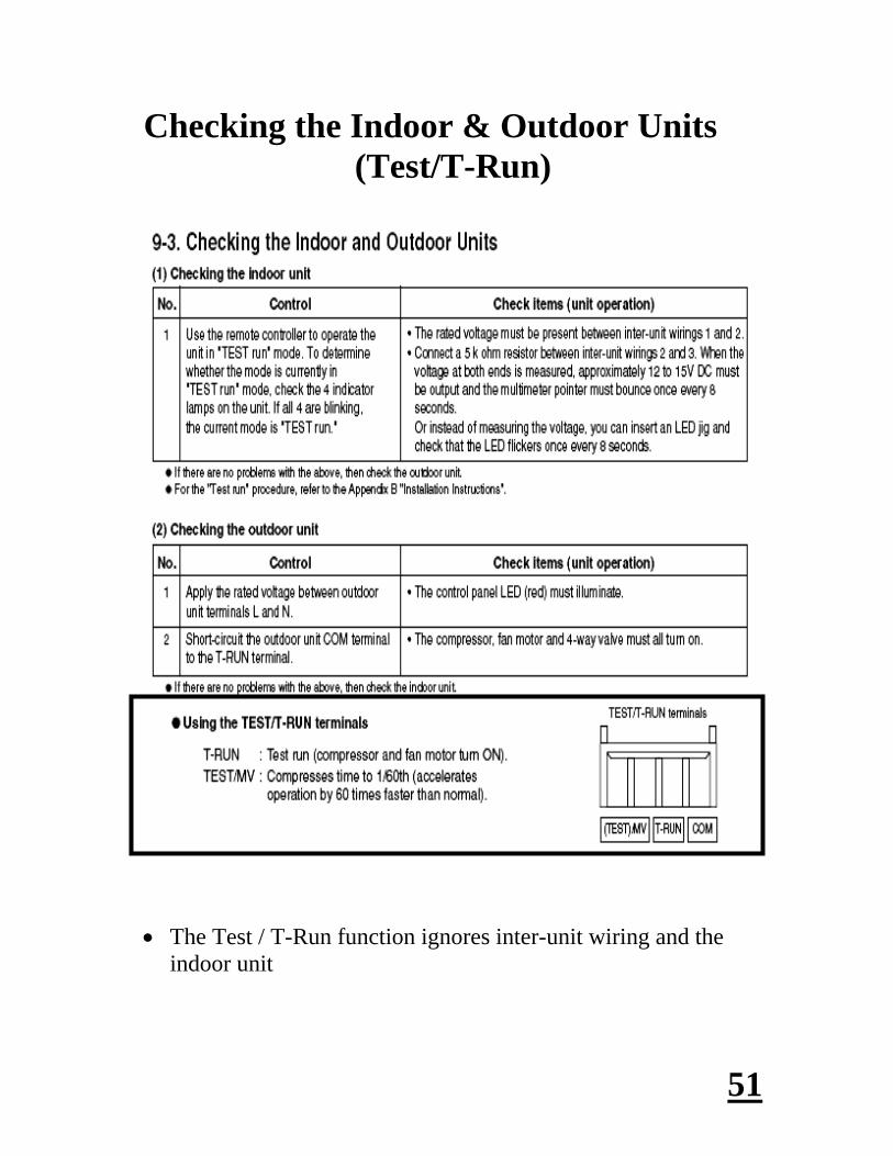
The Test / T-Run function ignores inter-unit wiring and the
indoor unit

52
Testing Of Outdoor Unit PCB
Short-circuit the T-RUN terminal to The COM terminal of TEST/T-RUN terminal.
The compressor, fan motor, and 4-way valve must turn ON.
This function will not work on a “C” model and the outdoor temperature is below 50 degrees.
Common Terminal
Remove plastic cover to the main PCB board. Look for the T-RUN/TEST on the edge of the board.
Use a screwdriver and short between Common and C48. The compressor, fan and 4 way valve will turn on.

53
Serial Communication Error (Identification Procedure)

54
Serial Communication Error (Identification Procedure)

55
Serial Communication Error (Identification Procedure)

56
Procedure for Replacing (The Outdoor Board)
When replacing the outdoor board it is necessary to re-apply heat sink compound.
This compound is applied to the heat dissipating pads on the circuit board.
Do not use the whole container. Apply a THIN layer only.
Instructions and heat sink paste should be in the box with the replacement board
If the paste is not included it can be purchased at any electronics store.

57
Flexi-Multi (Outdoor PCB Error Lamps)
In Normal Operation These Error Lamps Should Not Be Lit.

58
Troubleshooting Chart Flexi-Multi, Single Heat Pump, Single Cooling,
Single Cooling Low Ambient
Trouble Diagnosis of each part
Inspection Points
Problems
Inspection Points
Problems
For details about the inspection points, refer to the inspection points for each part.
Inspection points: Read across from left to right
Problems: Read down from top to bottom
Example: Indoor unit does not operate. Check controller and indoor circuit board

59
Checking the EEV (Electronic Expansion Valve)
Refco Part Number SVOM-18
Remove the EEV coil Place the tool over the EEV stem
Rotate 5 revolutions CW to close valve. Start unit and measure temp difference across EEV. Then rotate 5 revolutions CCW to open valve while system is
running. Operation is normal if temperature changes.
Checking the coil resistance
Single Zone (6 wire) Check resistance between: • Gray to Yellow • Gray to Orange • White to Black • White to Red OK if 46 +/- 4 Ohm on each
Flexi-Multi (5 wire) Check resistance between: • Gray to Yellow • Gray to Orange • Gray to Black • Gray to Red OK if 46 +/- 4 Ohm on each

60
Thermistor Values
All resistances shown in “K” ohm values
Sensor errors will display as “S” codes through diagnostics.
Example: S01= Room temperature sensor failure
Indoor air temperature sensor
Indoor heat exchanger sensor
Outdoor air temperature sensor

61
Before Calling Sanyo Technical Support (Check the items on this list)
RAC Troubleshooting Procedures For 9-24,000 BTU mini splits and all Flexi Multi.
1- No Light on Outdoor Board A- Check Power Supply. B- Check the fuse on board. If the fuse is soldered in, by pass it with an in line fuse holder until the short is located, this includes checking ohms on all components. Ohm terminals 1, 2 and 3 to ground. Visually check board and for any other possible shorts. If the fuse was good or bad, proceed to the next steps. C- Ohm reactor. It should be (.3-.4 ohms). D- Turn the power off and wait for it to dissipate. Disconnect the fan motor, compressor, crank case heater and the expansion valve from the board. If it is a flexi model, disconnect the expansion valve board. Turn the power on and check if the board light is on. If it isn’t, the board is bad. If it is, one of the components is bad and ohms need to be checked. Check the fan motor to ground. Check through the compressor windings and to ground. Mega ohm the
windings because we have seen the DC compressors run (for a short time) when they are partially grounded.
Check the crank case heater. Check the expansion valve. Ohm from the grey wire to the other wires in
the expansion valve connector and you should read 46+ or minus 4 ohms. On Flexi models visually check the expansion board and ohm any
expansion valves that plug into it. E- Plug each component back in one at a time until the light starts flashing or the light goes out and you have most likely found the bad component. Remember to turn the power off and let it dissipate each time before plugging another component back in.

62
2- Flashing light on Outdoor Board
Follow steps A-D in section 1 (No light on the outdoor board) and power
the unit with the fan, compressor, crankcase heater and expansion valve disconnected.
Once you have a solid light, plug each component back in one at a time.
Remember to cycle the power and let it dissipate each time.
If you plug the fan motor in and this cause’s the light to flash it could be the board or the motor. There is no way to tell which one is bad. I would suggest ordering both parts and plugging the motor in first, to see if this resolves the problem since it is the easiest to check.
3- No Lights On at the Indoor Unit Check power supply at terminals 1 and 2. Is there a condensate pump
with an open safety switch? If you have power and the unit will not respond to the remote proceed to next check.
Check fuse on board. If the fuse on the board is blown, check all components that plug into the board. Verify that 220 volts was not run to a 110 volt unit.
Try to start the unit with the manual (push button) on off button located
in the bottom right hand corner (K models). If this does not work, change the board and the receiver.
If the unit starts with the button, check the remote for proper addressing.
Try resetting the remote by pushing the ACL button for 3-4 seconds.
You can test the remote to see if it is sending a signal with an AM radio. Hold the remote next to the turned on AM radio and push one of the buttons on the remote. If you hear interference through the radio’s speaker, the remote is working. Try it in several locations on the radio before condemning the remote.
If the remote checks good but the unit will still not respond to it, replace
the board and the receiver.
63
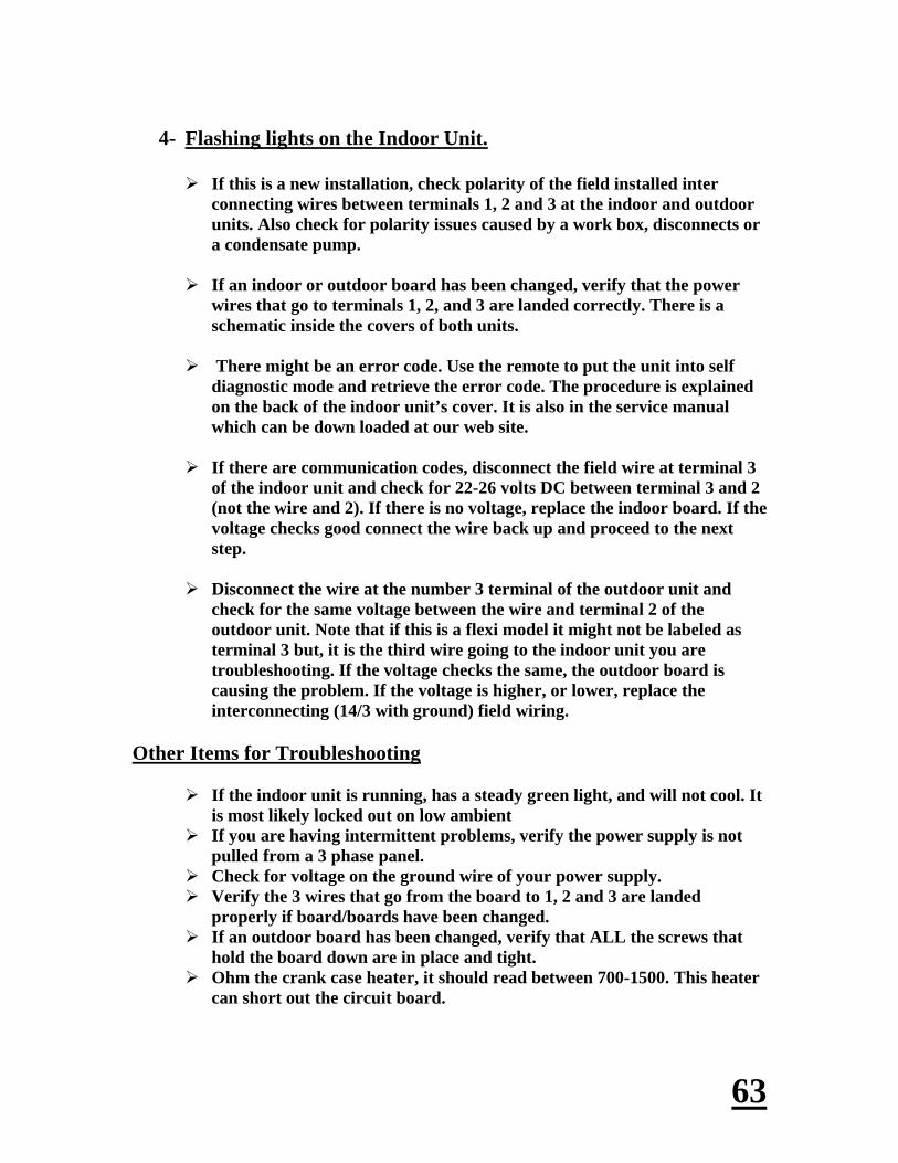
4- Flashing lights on the Indoor Unit. If this is a new installation, check polarity of the field installed inter
connecting wires between terminals 1, 2 and 3 at the indoor and outdoor units. Also check for polarity issues caused by a work box, disconnects or a condensate pump.
If an indoor or outdoor board has been changed, verify that the power
wires that go to terminals 1, 2, and 3 are landed correctly. There is a schematic inside the covers of both units.
There might be an error code. Use the remote to put the unit into self
diagnostic mode and retrieve the error code. The procedure is explained on the back of the indoor unit’s cover. It is also in the service manual which can be down loaded at our web site.
If there are communication codes, disconnect the field wire at terminal 3
of the indoor unit and check for 22-26 volts DC between terminal 3 and 2 (not the wire and 2). If there is no voltage, replace the indoor board. If the voltage checks good connect the wire back up and proceed to the next step.
Disconnect the wire at the number 3 terminal of the outdoor unit and
check for the same voltage between the wire and terminal 2 of the outdoor unit. Note that if this is a flexi model it might not be labeled as terminal 3 but, it is the third wire going to the indoor unit you are troubleshooting. If the voltage checks the same, the outdoor board is causing the problem. If the voltage is higher, or lower, replace the interconnecting (14/3 with ground) field wiring.
Other Items for Troubleshooting
If the indoor unit is running, has a steady green light, and will not cool. It is most likely locked out on low ambient
If you are having intermittent problems, verify the power supply is not pulled from a 3 phase panel.
Check for voltage on the ground wire of your power supply. Verify the 3 wires that go from the board to 1, 2 and 3 are landed
properly if board/boards have been changed. If an outdoor board has been changed, verify that ALL the screws that
hold the board down are in place and tight. Ohm the crank case heater, it should read between 700-1500. This heater
can short out the circuit board.

64
26,000-42,000 Btu Models
PAC Product Professional Air Conditioning

65
Product Line-Up (Outdoor units)
All PAC systems are Low Ambient & rated to 0 degrees out door temperature.
Appearance
Capacity C/H (BTU)
Dimensions (inches) Weight (lbs)
Power Supply
Operation Range
Production
26,000BTU 30,000BTU 36,000BTU 42,000BTU
Cooling/Heating 26,000/30,800
H 30-11/16 x W 37 X D 13-3/8
128 lbs
Single phase 208-230 V, 60Hz
Cooling 0° F ~ 109° F Heating 5° F ~ 75° F
DALLIAN SANYO Air Conditioner Co., Ltd.
Cooling/Heating 30,000/34,800
H 30-11/16 x W 37 X D 13-3/8
143 lbs
Cooling/Heating 33,500/37,400
Cooling/Heating 39,500/48,000
H 48-15/32 x W 37 X D 13-3/8
220 lbs

66
Product Line-Up (Indoor units)
All Systems Are Low Ambient 0 degrees outdoor
temperature
K
T
X
U
Indoor Unit
Outdoor unit DC Inverter
DC Fan motor
30,000BTU SC HP
42,000BTU
SC
SC
HP
HP
26,000BTU SC HP
SC
SC
SC
HP
HP
HP
36,000BTU SC HP
SC
SC
SC
HP
HP
HP

67
KHS Models (Wall Mounted)
Cooling and heat pump capable
• Sleek Design
• Easily serviceable
• Low operating sound
• Wireless remote control (Included)
• Wired remote control (Optional)
RCS-SH1UA Wireless remote control
(standard)
RCS-TM80BG Wired remote control
(Optional)

68
THW Models (Ceiling Suspended)
RCS-TM80BG Wired remote control
(Standard)
RCS-SH80UA Wireless Remote Control kit
(Optional)
Cooling and Heat Pump Capable • Fresh air capability
• Wired remote (Included)
• Wireless remote (Optional)
• Low operating sound

69
XHW Models (Ceiling Recessed)
12,000 & 18,000 Btu Models Available True 2 ft. X 2 ft. Footprint
RCS-TM80BG Wired remote control
(Standard)
RCS-SH80UA Wireless remote control kit
(Optional)
Cooling and Heat Pump Capable • Wired remote (Include
• Wireless remote (Optional)
• Adjustable 4 way air discharge
• Fresh air capability [ Plenum Required]
• Remote ducting (Optional)
• Built in condensate pump (10” lift)

70
UHW Models (Concealed Duct)
RCS-TM80BG Wired remote control
(Standard)
RCS-SH80UA Wireless remote control kit
(Optional)
Cooling and heat pump capable • Twenty Five (25’) MAXIMUM duct run per outlet
• Wired remote (Included)
• Wireless remote (Optional)
• Ducted model [8”] with convertible return opening

71
Operation Range (26,000-42,000 Btu Models)
For windy locations Sanyo recommends a wind baffle installed on the outdoor unit for low ambient operation.
Sanyo Wind Baffle Part # WIND-B1
The dimensions for the wind baffles can be found in the installation manual.

72
No additional compressor oil charge is necessary
Tubing sizes, Length and Elevation Difference Refrigerant Charge, Adjustment & Insulation Chart.
R401A 0.43oz.
Both Tubes seperately
1/2 inch insulation
42TS72R
42XS72R
42TH72R
42XH72R
36TH72R
36XH72R
36UH72R
36THH72R
36TS72R
36XS72R
36US72R
36KH72R
26THH72R
30KS72R
30KH72R
36KS72R
26TH72R
26XH72R
26UH72R
26KHH72R
26TS72R
26XS72R
26US72R
26KH72R
MAXIMUM LENGTH (ft) OF TUBING AT SHIPMENT
REQUIRED ADDITIONAL REFRIGERANT OZ/FT
INSULATION BOTH TUBES
26KS72R
3/8 5/8 165' 100' 50' 100'
MAXIMUM LENGTH ft. OF TUBING BETWEEN
IN/OUTDOOR
MAXIMUM ELEVATION DIFFERENCE (ft) BETWEEN
IN/OUTDOOROUTDOOR
ABOVEOUTDOOR
BELOW
SYSTEM MODELSOD TUBE SIZE (inches)
NARROW WIDE

73
Electrical wiring (26,000-42,000 BTU Systems)
Dual or single point line voltage
18/2 shielded wire is required and must be grounded at one end

74
Recommended (Wire length and diameter)
Follow local electrical codes

75
Remote Controller (Options)
2.System controller (SHA-KC64UG)
1. Timer remote controller (RCS-TM80BG)
3. Wireless remote controller (RCS-SH1UA, RCS-SH80UA-WL, RCS-BH80UA-WL)
4. Simple remote RCS-KR1AGB

76
RCS-TM80BG (Functions)
• On/Off
• Mode selection
– cooling, heating, dry, auto, fan
– Auto changeover
• Set temperature
– Cooling/Dry: 64 to 86
– Heating: 61 to 86
• Fan speed: Auto, low, high, high-high
• Air direction
• 7 day programmable (6 events/day)
• Controls up to 8 indoor units
• Main or sub on same unit or group

77
Using the RCS-TM80BG (Monitoring, diagnostic & EPROM setting)
Wire nut black and white from the RCS-TM80BG to the connector
Plug the male end of the connector into the female connector marked “RC” on the outdoor circuit board. The “RC” connector on the indoor can be used for applications with only wireless remote control.
Sanyo connector part # 623-178-5082

78
Monitoring Indoor & Outdoor (Sensor Temperatures)
RCS-TM80BG Functions as a Service Tool
Example: Code 1, Refrigerant Circuit 1, Unit 1.
Remote controller temperature of 85 degrees
0085 Unit No. 1-1
Code No. 01
The LCD display changes to sensor temperature, Unit no. and code no.
Use the Temp Setting Keys to scroll through codes (Sensor Address)
For group control press the Unit key to the address of the unit to monitor
To monitor the outdoor sensors plug the connector into the “RC” jack on the outdoor circuit board and follow the above procedure.
Press the Wrench key to return to normal display when finished

79
Monitoring Indoor & Outdoor (Error codes)
•Press the “Set” and the button that looks like a “Wrench” together for 4 seconds or more.
•Use the temperature “Up & down Arrows” to scroll through the 8 codes in the outdoor memory. There are up to 4 codes stored on the indoor memory
•Code 1 is the newest and 4 is the oldest code that the unit has faulted out on.
•Refer to your error code list in the service manual for code explanations and course of action for repairs.
•To clear all codes press the “Cancel Button”.
•Press the button that looks like a “Wrench” to exit trouble history.
•Install RC plug back into the outdoor / indoor unit and install the remote back in place.

80
Indoor and Outdoor (EPROM settings)
For a complete listing of the eprom codes download a service manual from www.us.sanyo/hvac.com
Indoor EPROM settings
Outdoor EPROM settings

81
Wireless Remote Controller (Switch Setting)
RCS-SH1UA Wireless Remote Control for “K” style indoor units have a built-in receiver installed.
(26-42,000 BTU Models)
Dip switch setting must be changed when wireless remote is utilized.
• To Allow Wireless Control of Wall Mounted PAC Series
– Locate SW101 on the indoor PCB
– Setting for wired remote • DIP 1, 2 = Off • DIP 3 = On
– Setting for wireless remote • DIP 1, 2, 3 = Off

82
Commissioning the system (Initial Startup)
When determining if an auto address failure has taken place you will need to look at the indicator lamp assembly.
This lamp assembly will be located on the indoor unit’s receiver, which receives and transmits the signal from the remote controller to the indoor units PCB assembly.
The green “Operation Lamp” will be “Blinking” indicating that a fault has taken place and no operation of either the indoor or outdoor unit will be possible.
When a wired remote controller is utilized where no receiver is needed, then the error code will be shown on the display screen of the remote.
All “Error Codes” can be located in the troubleshooting section of the service and technical
manual.
Operation Light “Blinking”
P 22
Errors will be displayed on the remote Example: P22=Outdoor fan failure
Reset Procedure for Auto Address Failure on the 26,000 Btu to 42,000 Btu Models

83
Reset Procedure for Auto Address Failure (26,000 Btu to 42,000 Btu Models)
When utilizing the wireless type remote it will be necessary to go to the outdoor units PCB assembly and locate the two lamps on the main board marked “LED 1 & LED 2”. These are the error lamps.
The lamps will blink a certain way indicating what type of failure has taken place
with the units.
For example both lamps blinking together simultaneously are indicative of an “Auto Address Failure”.
If the lamps are blinking separately you must count the number of blinks on
each lamp to determine the precise code.
LED 1
LED 2

84
Probable Causes Auto address failure or communication errors
Indoor and outdoor units not powered within 6 minutes at initial startup.
The communication (U1 & U2) line is broken.
A good communication line should ohm out at around 100 ohm’s at the indoor and outdoor units U1 & U2 terminals
Indoor unit at U1 & U2 communication line
Outdoor unit at U1 & U2 communication line

85
Probable Causes Auto address failure or communication errors
The probable cause of a blown fuse is line voltage has been applied to the U1 & U2 communication line
At the outdoor circuit board if 100 ohm’s not detected on the U1 & U2 line then check the fuse. If the fuse is bad then move the molex plug from the OC to the EMG socket.
EMG
OC
Fuse
EMG
OC
Fuse
At the indoor circuit board even if 100 ohm’s is detected on the U1 & U2 line then check the fuse. If the fuse is bad then move the molex plug from the OC to the EMG socket.

86
Reset Procedure for Auto Address Failure (26,000-42,000 BTU Models)
At the outdoor unit’s circuit board if the lamps are blinking
separately count the number of blinks on each lamp to determine the precise code.
If the lamps are blinking simultaneously this is an auto address
failure
LED 1
LED 2
Alternate blinking during alarms key: LED 1 blinks M times, then LED 2 blinks N times. The cycle repeats. M=2: P alarm 3:= H alarm 4:= E alarm 5:= F alarm 6:= L alarm N= alarm number

87
Reset Procedure for Auto Address Failure (26,000-42,000 BTU Models)
When re-addressing the indoor and outdoor units, you must first go to the outdoor units PCB assembly and locate the “Black Button” marked “Auto Add”.
First shut off the outdoor units power by de-energizing the disconnect switch and waiting for the lamps on the board to go completely out.
Then re-energize the circuit and then push in the “Black Button” for approximately four seconds or until the lights marked “LED 1 and LED 2” start alternating back and forth.
Eventually, these two lamps should go completely off if the auto addressing process was successful. Please note this can take several minutes to complete.

88
Outdoor Circuit Board
Troubleshooting (26,000- 42,000 BTU Models)
If no operation of indoor or outdoor units exist always check terminals 1 & 2 of the indoor unit to verify 208/230v is present.
Check the indoor & outdoor boards to verify that the red power led is illuminated. If the light is not lit, check the power transformer for secondary voltages: (2 red wires= 14.8vac) (2 brown wires= 14.8vac) 2 orange wires= 20vac)
If all voltages are confirmed with no operation then proceed to the outdoor unit. On the outdoor main pcb board check the led lights marked 1 & 2. Both lamps should be off in normal operation.
If they are lit this represents an error code. If they are both blinking together this represents an auto-address failure. Power the system down and wait until all led’s go completely out.
Press and hold the black button marked “auto add” for 5-10 seconds until led’s 1 & 2 start alternating blinking. Release the button. The system is now addressing. This process can take up to 5 minutes or more. If both lights go completely out the system is now addressed.
LED1, 2 Power LED EEPROM (Unit data)
Auto Add Button
Refrigerant System
FUSE (2)

89
Meaning of Alarm Messages (Wired Remote vs. Wireless)
P 10
Wired remote codes show in the display P10 Code= Float switch open
Wireless remote codes leave more possibilities. Watch the Operation, Timer & Standby Lights. Are they alternating or blinking on the indoor unit. The same P10 code on the wired remote has three possibilities with the wireless remote. P01, P09 or P10

90
Meaning of Alarm Messages
Wired Remote: Code is on the display of the remote Wireless: Blinking/Alternating lights on indoor unit

91
Meaning of Alarm Messages

92
Meaning of Alarm Messages

93
Meaning of Alarm Messages

94
Meaning of Alarm Messages

95
Meaning of Alarm Messages

96
Details of alarm messages

97
Details of alarm messages

98
Details of alarm messages

99
Details of alarm messages

100
Troubleshooting (HIC PCB assembly)
+ WVU
COMPRESSOR WIRES
NEGATIVE DISCHARGE POST
POSITIVE DISCHARGE POST
COMPRESSOR TERMINALS U= Run winding (Red wire)
V= Common winding (White wire)
W= Start winding (Blue wire)
Heat sink paste is applied to the back when replacing the board

101
Filter Board (26,000-42,000 Btu Models)
Safety Note:
The filter board holds an electrical charge
Use the discharge posts when servicing
DISCHARGE POSTS
FUSE 250V 25AMP

102
One Remote Can Control Up To Eight Systems
Example: The first indoor is set as the MAIN and up to 7 more are set to SUB.

103
Replacing an Indoor or Outdoor (PCB Board)
Instructions are included with your replacement board.
The EPROM chip on the replacement board is BLANK.
You must RE-USE the EPROM chip from the old board
Remove the chip from the old board and place in the new board
If the chip is not changed a common error code will be a “L” or unit mismatch error code

104
Indoor & outdoor unit PCB assembly (26,000-42,000 Btu’s)
EPROM chip is marked ICO8 on the indoor board
EPROM chip is marked IC007 on the outdoor board

105
EPROM Chip Installation
Match the “Half Moon” on the socket and the “Half Moon” on the face of the chip
“Half moon” on the face of the chip
“Half Moon” in the socket

106
EPROM Chip Installation
If error occurs remove chip and check for proper rotation and seating.

107
Performance Data Cooling characteristics:
Indoor Unit: KHS0971 Outdoor Unit: CH0971
(RH: 46%, indoor fan speed: High fan, 60hz. 115v)
Check each performance value in the test-run mode. Electrical performance values represent a combined indoor/outdoor value.

108
Performance Data
Heating characteristics:
Indoor Unit: KHS0971 Outdoor Unit: CH0971
(RH: 46%, indoor fan speed: High fan, 60hz. 115v)
Check each performance value in test-run mode. Electrical performance values represent a combined indoor/outdoor value.

109
Performance Data
Cooling characteristics:
Indoor Unit: KS0971 Outdoor Unit: C0971
(RH: 46%, indoor fan speed: High fan, 60hz. 115v)
Check each performance value in test-run mode. Electrical performance values represent a combined indoor/outdoor value.

110
Performance Data
Cooling characteristics:
Indoor Unit: K0971 Outdoor Unit: CL0971
(RH: 46%, indoor fan speed: High fan, 60hz. 115v)
Check each performance value in test-run mode. Electrical performance values represent a combined indoor/outdoor value.

111
Performance Data
Cooling characteristics:
Indoor Unit: KHS1271 Outdoor Unit: CH1271
(RH: 46%, indoor fan speed: High fan, 60hz. 115v)
Check each performance value in test-run mode. Electrical performance values represent a combined indoor/outdoor value.

112
Performance Data
Heating characteristics:
Indoor Unit: KHS1271 Outdoor Unit: CH1271
(RH: 46%, indoor fan speed: High fan, 60hz. 115v)
Check each performance value in test-run mode. Electrical performance values represent a combined indoor/outdoor value.

113
Performance Data
Cooling characteristics:
Indoor Unit: KHS1872 Outdoor Unit: CH1872
(RH: 46%, indoor fan speed: High fan, 60hz. 115v)
Check each performance value in test-run mode. Electrical performance values represent a combined indoor/outdoor value.

114
Performance Data
Heating characteristics:
Indoor Unit: KHS1872 Outdoor Unit: CH1872
(RH: 46%, indoor fan speed: High fan, 60hz. 115v)
Check each performance value in test-run mode. Electrical performance values represent a combined indoor/outdoor value.

115
Performance Data
Cooling characteristics:
Indoor Unit: KS1872 Outdoor Unit: C1872
(RH: 46%, indoor fan speed: High fan, 60hz. 115v)
Check each performance value in test-run mode. Electrical performance values represent a combined indoor/outdoor value.

116
Performance Data
Cooling characteristics:
Indoor Unit: KS1872 Outdoor Unit: CL1872
(RH: 46%, indoor fan speed: High fan, 60hz. 115v)
Check each performance value in test-run mode. Electrical performance values represent a combined indoor/outdoor value.

117
Performance Data
Cooling characteristics:
Indoor Unit: KHS2472 Outdoor Unit: CH2472
(RH: 46%, indoor fan speed: High fan, 60hz. 115v)
Check each performance value in test-run mode. Electrical performance values represent a combined indoor/outdoor value.

118
Performance Data
Heating characteristics:
Indoor Unit: KHS2472 Outdoor Unit: CH2472
(RH: 46%, indoor fan speed: High fan, 60hz. 115v)
Check each performance value in test-run mode. Electrical performance values represent a combined indoor/outdoor value.

119
Performance Data
Cooling characteristics:
Indoor Unit: KS2472 Outdoor Unit: C2472
(RH: 46%, indoor fan speed: High fan, 60hz. 115v)
Check each performance value in test-run mode. Electrical performance values represent a combined indoor/outdoor value

120
Performance Data
Cooling characteristics:
Indoor Unit: KS2472 Outdoor Unit: CL2472
(RH: 46%, indoor fan speed: High fan, 60hz. 115v)
Check each performance value in test-run mode. Electrical performance values represent a combined indoor/outdoor value

121
Thank You!