air-cooled series r helical-rotary...
TRANSCRIPT

Air-Cooled Series R™
Helical-Rotary LiquidChiller
Model RTAC 120 to 200
(400 to 760kw - 50 Hz)
Built for the Industrial and
Commercial Markets
RLC-PRC005-E4

The new Trane Model RTAC Air-CooledHelical-Rotary Chiller is the result of asearch for higher reliability, higherenergy efficiency, and lower soundlevels for today’s environment.
In an effort to reduce energy consumedby HVAC equipment and to continuallyproduce chilled water, Trane hasdeveloped the Model RTAC chiller withhigher efficiencies and a more reliabledesign than any other air cooled chilleravailable on the market today.
The Model RTAC chiller uses the provendesign of the Trane helical-rotarycompressor, which embraces all of thedesign features that have made theTrane helical-rotary compressor liquidchillers such a success since 1987.
Introduction
©American Standard Inc. 2000 RLC-PRC005-E4
Figure 1
What Is NewThe RTAC offers the same highreliability coupled with greatly improvedenergy efficiency, vastly reducedphysical footprint, and improvedacoustical performance, due to itsadvanced design, low-speed, direct-drive compressor, and proven Series R™ performance.
The major differences between theSeries R, Model RTAC and Model RTAAare:• Smaller physical footprint• Lower sound levels• Higher energy efficiency • Designed specifically for operating
with environmentally-safe HFC-134a.
The Series R Model RTAC helical-rotarychiller is an industrial-grade design, builtfor both the industrial and commercialmarkets. It is ideal for schools, hospitals,retailers, office buildings, and industrialapplications.

3RLC-PRC005-E4
Contents
Introduction
Features and BenefitsImproved Acoustical PerformanceSimple InstallationSuperior Control with Tracer™ Chiller ControlsOptions
Application Considerations
Selection Procedure
General Data
Performance DataPerformance Adjustment Factors
ControlsGeneric Building Automation System ControlsTypical Wiring DiagramsJob Site Data
Electrical Data
Dimensional Data
Mechanical Specifications
2
4
9
12
13
19
36
5678
33
45
47
50
363944

Features andBenefits
4 RLC-PRC005-E4
Water Chiller Systems Business Unit The Series R™
Helical-Rotary Compressor
• Unequaled reliability. The nextgeneration Trane helical-rotarycompressor is designed, built, andtested to the same demanding andrugged standards as the Trane scrollcompressors, the centrifugalcompressors, and the previousgeneration helical-rotary compressorsused in both air- and water-cooledchillers for more than 13 years.
• Years of research and testing. TheTrane helical-rotary compressor hasamassed thousands of hours oftesting, much of it at severe operatingconditions beyond normal commercialair-conditioning applications.
• Proven track record. The TraneCompany is the world’s largestmanufacturer of large helical-rotarycompressors used for refrigeration.Over 90,000 compressors worldwidehave proven that the Trane helical-rotary compressor has a reliability rateof greater than 99.5 percent in the firstyear of operation—unequalled in theindustry.
• Resistance to liquid slugging. Therobust design of the Series Rcompressor can ingest amounts ofliquid refrigerant that normally wouldseverely damage reciprocatingcompressor valves, piston rods, andcylinders.
• Fewer moving parts. The helical-rotarycompressor has only two rotatingparts: the male rotor and the femalerotor. Unlike reciprocatingcompressors, the Trane helical-rotarycompressor has no pistons,connecting rods, suction anddischarge valves, or mechanical oilpump. In fact, a typical reciprocatingcompressor has 15 times as manycritical parts as the Series Rcompressor. Fewer moving parts leadsto increased reliability and longer life.
• Direct-drive, low-speed, semi-hermeticcompressor for high efficiency andhigh reliability.
• Field-serviceable compressor for easymaintenance.
• Suction-gas-cooled motor. The motoroperates at lower temperatures forlonger motor life.
• Five minute start-to-start and twominute stop-to-start anti-recycle timerallows for closer water-looptemperature control.

Improved Acoustical Performance
5RLC-PRC005-E4
The sound levels of the Series R ModelRTAA have been steadily improvedsince its introduction. With the advent ofthe Model RTAC, sound levels arereduced significantly by addressing twomajor sources: the compressor and therefrigerant piping. First, the compressorhas been specifically designed tominimize sound generation. Second, therefrigerant components and piping havebeen optimized to reduce soundpropagation throughout the system. Theresult: sound levels achieved on theModel RTAC represent the lowest soundlevels ever on Trane air-cooled helical-rotary compressor water chillers.
Superior Efficiency Levels:The Bar Has Been RaisedThe standard-efficiency Trane ModelRTAC has COP levels up to 2.90 kW/kW[9.9 EER] (including fans), while thepremium-efficiency, or high-efficiency,units leap to COP levels of 3.08 kW/kW[10.51 EER] (including fans).
The modern technology of the RTACwith the efficient direct-drivecompressor, the flooded evaporator, theunique design to separate liquid andvapor, the electronic expansion valve,and the revolutionary Tracer™ ChillerControls, has permitted Trane to achievethese efficiency levels, unmatched in theindustry.
Precise Rotor Tip ClearancesHigher energy efficiency in a helical-rotary compressor is obtained byreducing the rotor tip clearances. Thisnext-generation compressor is noexception. With today’s advancedmanufacturing technology, clearancescan be controlled to even tightertolerances. This reduces the leakagebetween high- and low-pressure cavitiesduring compression, allowing for moreefficient compressor operation.
Capacity Control and Load MatchingThe combination patented unloadingsystem on Trane helical-rotarycompressors uses the variable
unloading valve for the majority of theunloading function. This allows thecompressor to modulate infinitely, toexactly match building load and tomaintain chilled-water supplytemperatures within ± 0.3°C [±0.5°F] ofthe set point. Reciprocating and helical-rotary chillers that rely on steppedcapacity control must run at a capacityequal to or greater than the load, andtypically can only maintain watertemperature to around ± 1°C [±2°F].Much of this excess capacity is lostbecause overcooling goes towardremoving building latent heat, causingthe building to be dried beyond normalcomfort requirements. When the loadbecomes very low, the compressor alsouses a step unloader valve, which is asingle unloading step to achieve theminimum unloading point of thecompressor. The result of this design isoptimized part-load performance farsuperior to single reciprocatingcompressors and step-only helical-rotary compressors.
������������� ������������������

Simple Installation
6 RLC-PRC005-E4
Compact Physical SizeThe Trane Model RTAC chiller averages a20 percent reduction in physicalfootprint, while the greatest change isactually 40 percent smaller whencompared against the previous design.This improvement makes the RTAC thesmallest air-cooled chiller in the industryand a prime candidate for installationsthat have space constraints. All physicalsizes were changed without sacrificingthe side clearances needed to supplyfresh airflow without coil starvation—thetightest operational clearances in theindustry.
Close Spacing InstallationThe air-cooled Series R™ chiller has thetightest recommended side clearance inthe industry, 1.2 meters, but that is notall. In situations where equipment mustbe installed with less clearance thanrecommended, which frequently occursin retrofit applications, restricted airflowis common. Conventional chillers maynot work at all. However, the air-cooledSeries R chiller with the AdaptiveControl™ microprocessor will make asmuch chilled water as possible given theactual installed conditions, stay on-lineduring any unforeseen abnormalconditions, and optimize itsperformance. Consult your Trane salesengineer for more details.
Factory Testing Means Trouble-FreeStart-upAll air-cooled Series R chillers are givena complete functional test at the factory.This computer-based test programcompletely checks the sensors, wiring,electrical components, microprocessorfunction, communication capability,expansion valve performance, and fans.In addition, each compressor is run-tested to verify capacity and efficiency.Where applicable, each unit is factorypreset to the customer’s designconditions. An example would be theleaving-liquid temperature set point. Theresult of this test program is that thechiller arrives at the job site fully testedand ready for operation.
Factory-Installed and Tested Controlsand Options Speed InstallationAll Series R chiller options, includingmain power-supply disconnect, lowambient control, ambient temperaturesensor, low ambient lockout,communication interface and ice-making controls are factory installed andtested. Some manufacturers sendaccessories in pieces to be fieldinstalled. With Trane, the customer saveson installation expense and hasassurance that ALL chiller controls andoptions have been tested and willfunction as expected.
Superior Control with Tracer™ Chiller Controls
7RLC-PRC005-E4
The End of Nuisance Trip-Outs and Unnecessary Service Calls? The Adaptive Control™ microprocessorsystem enhances the air-cooled Series Rchiller by providing the very latest chillercontrol technology. With the AdaptiveControl microprocessor, unnecessaryservice calls and unhappy tenants areavoided. The unit does not nuisance-tripor unnecessarily shut down. Only whenthe Tracer chiller controls haveexhausted all possible correctiveactions, and the unit is still violating anoperating limit, will the chiller shutdown. Controls on other equipmenttypically shut down the chiller, usuallyjust when it is needed the most.
For Example:A typical five-year-old chiller with dirtycoils might trip out on high-pressurecutout on a 38°C [100°F] day in August.A hot day is just when comfort coolingis needed the most. In contrast, the air-cooled Series R chiller with an AdaptiveControl microprocessor will stage fanson, modulate the electronic expansionvalve, and modulate the slide valve as itapproaches a high-pressure cutout,thereby keeping the chiller on line whenyou need it the most.
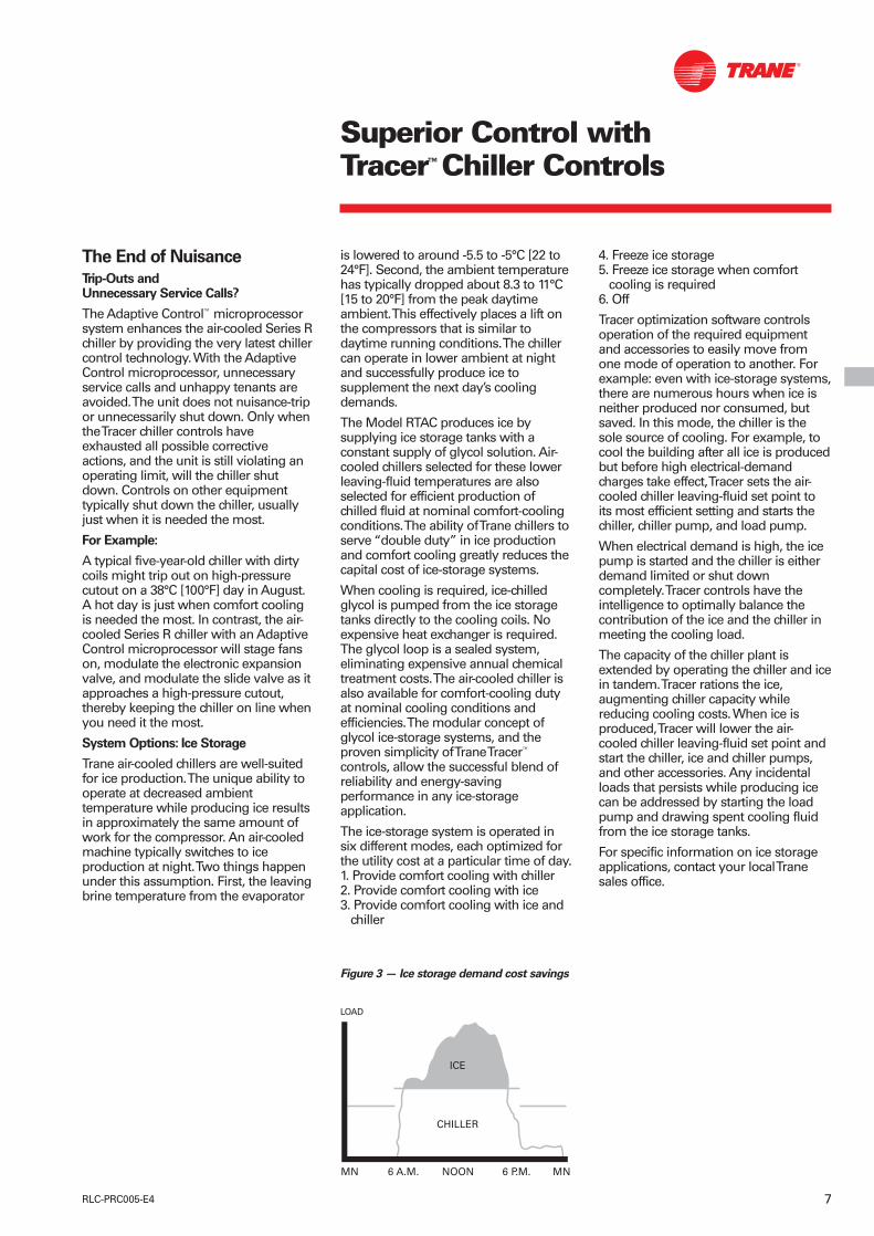
System Options: Ice StorageTrane air-cooled chillers are well-suitedfor ice production. The unique ability tooperate at decreased ambienttemperature while producing ice resultsin approximately the same amount ofwork for the compressor. An air-cooledmachine typically switches to iceproduction at night. Two things happenunder this assumption. First, the leavingbrine temperature from the evaporator
4. Freeze ice storage5. Freeze ice storage when comfort
cooling is required6. Off
Tracer optimization software controlsoperation of the required equipmentand accessories to easily move fromone mode of operation to another. Forexample: even with ice-storage systems,there are numerous hours when ice isneither produced nor consumed, butsaved. In this mode, the chiller is thesole source of cooling. For example, tocool the building after all ice is producedbut before high electrical-demandcharges take effect, Tracer sets the air-cooled chiller leaving-fluid set point toits most efficient setting and starts thechiller, chiller pump, and load pump.
When electrical demand is high, the icepump is started and the chiller is eitherdemand limited or shut downcompletely. Tracer controls have theintelligence to optimally balance thecontribution of the ice and the chiller inmeeting the cooling load.
The capacity of the chiller plant isextended by operating the chiller and icein tandem. Tracer rations the ice,augmenting chiller capacity whilereducing cooling costs. When ice isproduced, Tracer will lower the air-cooled chiller leaving-fluid set point andstart the chiller, ice and chiller pumps,and other accessories. Any incidentalloads that persists while producing icecan be addressed by starting the loadpump and drawing spent cooling fluidfrom the ice storage tanks.
For specific information on ice storageapplications, contact your local Tranesales office.
is lowered to around -5.5 to -5°C [22 to24°F]. Second, the ambient temperaturehas typically dropped about 8.3 to 11°C[15 to 20°F] from the peak daytimeambient. This effectively places a lift onthe compressors that is similar todaytime running conditions. The chillercan operate in lower ambient at nightand successfully produce ice tosupplement the next day’s coolingdemands.
The Model RTAC produces ice bysupplying ice storage tanks with aconstant supply of glycol solution. Air-cooled chillers selected for these lowerleaving-fluid temperatures are alsoselected for efficient production ofchilled fluid at nominal comfort-coolingconditions. The ability of Trane chillers toserve “double duty” in ice productionand comfort cooling greatly reduces thecapital cost of ice-storage systems.
When cooling is required, ice-chilledglycol is pumped from the ice storagetanks directly to the cooling coils. Noexpensive heat exchanger is required.The glycol loop is a sealed system,eliminating expensive annual chemicaltreatment costs. The air-cooled chiller isalso available for comfort-cooling dutyat nominal cooling conditions andefficiencies. The modular concept ofglycol ice-storage systems, and theproven simplicity of Trane Tracer™
controls, allow the successful blend ofreliability and energy-savingperformance in any ice-storageapplication.
The ice-storage system is operated insix different modes, each optimized forthe utility cost at a particular time of day.1. Provide comfort cooling with chiller2. Provide comfort cooling with ice3. Provide comfort cooling with ice and
chiller
Figure 3 — Ice storage demand cost savings
MN 6 A.M. NOON 6 P.M. MN
ICE
CHILLER
LOAD

Premium Efficiency andPerformance OptionThis option provides oversized heatexchangers with two purposes. One, itallows the unit to be more energyefficient. Two, the unit will haveenhanced operation in high-ambientconditions.
Low-Temperature BrineThe hardware and software on the unitare factory set to handle low-temperature brine applications, typicallybelow 5°C [41°F].
Ice MakingThe unit controls are factory set tohandle ice making for thermal storageapplications.
Tracer Summit™ CommunicationInterfacePermits bi-directional communication tothe Trane Integrated Comfort™ system.
Remote Input OptionsPermits remote chilled-liquid set point,remote current-limit set point, or both,by accepting a 4-20 mA or 2-10 VDCanalog signal.
Remote Output OptionsPermits alarm relay outputs, ice-makingoutputs, or both.
Chilled-Water ResetThis option provides the control logicand field-installed sensors to resetleaving-chilled-water temperature. Theset point can be reset based on eitherambient temperature or returnevaporator-water temperature.
Night Noise SetbackAt night, on contact closure all the fansrun at low speed, bringing the overallsound level further down.
SCR (Short-Circuit Rating)Offers a measure of safety for what thestarter-panel enclosure is able towithstand in the event of an explosioncaused by a short circuit; protection upto 35,000 amps is available on mostvoltages.
Neoprene IsolatorsIsolators provide isolation between thechiller and the structure to helpeliminate vibration transmission.Neoprene isolators are more effectiveand recommended over springisolators.
Victaulic Connection KitProvides a kit that includes a set of twopipe stubs and Victaulic couplings.
Low Noise VersionThe unit is equipped with low-speedfans and a compressor sound-attenuating enclosure. All thesound-emitting parts, like refrigerantlines and panels subject to vibration, areacoustically treated with sound-absorbent material.
Evaporator Freeze ProtectionFactory-installed and -wired traceheaters on the water boxes and on theintermediate tube plate, with an ambientthermostat and protected by a circuitbreaker.
Ground Fault DetectionSensing ground current for improvedchiller protection.
Protection GrillesProtection grilles cover the completecondensing coils and the service areasbeneath the coils.
Coil ProtectionA coated wire mesh that covers thecondenser coils only.
Access ProtectionA coated wire mesh that covers theaccess area underneath the condensercoils.
Service ValvesProvides a service valve on the suctionand discharge lines of each circuit tofacilitate compressor servicing.
High-Ambient OptionThe high-ambient option consists ofspecial control logic to permit high-ambient (up to 52°C [125°F]) operation.This option offers the best performancewhen coupled with the premiumefficiency and performance option.
Low-Ambient OptionThe low-ambient option consists ofspecial control logic and fans to permitlow-ambient (down to -23°C [-9°F])operation.
Low-Ambient LockoutA factory-installed ambient sensor andcontrol logic will prevent starting belowthe recommended ambienttemperature.
Power Disconnect SwitchA disconnect switch with a through-the-door handle, plus compressorprotection fuses, is provided todisconnect main power.
Options
8 RLC-PRC005-E4

Application Considerations
9RLC-PRC005-E4
Certain application constraints shouldbe considered when sizing, selecting,and installing Trane air-cooled Series Rchillers. Unit and system reliability isoften dependent on properly andcompletely complying with theseconsiderations. When the applicationvaries from the guidelines presented, itshould be reviewed with your localTrane sales engineer.
Unit SizingUnit capacities are listed in theperformance data section. Intentionallyoversizing a unit to ensure adequatecapacity is not recommended. Erraticsystem operation and excessivecompressor cycling are often a directresult of an oversized chiller. In addition,an oversized unit is usually moreexpensive to purchase, install, andoperate. If oversizing is desired, considerusing two units.
Water TreatmentDirt, scale, products of corrosion, andother foreign material will adverselyaffect heat transfer between the waterand system components. Foreign matterin the chilled-water system can alsoincrease pressure drop and,consequently, reduce water flow. Properwater treatment must be determinedlocally, depending on the type of system
51°C [125°F], and selecting the low-ambient option will increase theoperational capability of the water chillerto ambient temperatures as low as 18°C[0°F]. For operation outside of theseranges, contact the local Trane salesoffice.
Water Flow LimitsThe minimum water flow rates aregiven in Tables G-1 and G-2. Evaporatorflow rates below the tabulated valueswill result in laminar flow and causefreeze-up problems, scaling,stratification, and poor control. Themaximum evaporator water flow rate isalso given in the general data section.Flow rates exceeding those listed mayresult in excessive tube erosion.
Flow Rates Out of RangeMany process cooling jobs require flowrates that cannot be met with theminimum and maximum publishedvalues within the Model RTACevaporator. A simple piping change canalleviate this problem. For example: aplastic injection molding processrequires 5.0 Lps [80 gpm] of 10°C [50°F]water and returns that water at 15.6°C[60°F]. The selected chiller can operate atthese temperatures, but has a minimumflow rate of 7.6 Lps [120 gpm]. Thefollowing system can satisfy the process.
and local water characteristics. Neithersalt nor brackish water is recommendedfor use in Trane air-cooled Series Rchillers. Use of either will lead to ashortened chiller life. The TraneCompany encourages the employmentof a reputable water-treatment specialist,familiar with local water conditions, toassist in this determination and in theestablishment of a proper water-treatment program.
Effect of Altitude on CapacityAir-cooled Series R chiller capacitiesgiven in the performance data tables arefor use at sea level. At elevationssubstantially above sea level, thedecreased air density will reducecondenser capacity and, therefore, unitcapacity and efficiency. The adjustmentfactors in Table F-1 can be applieddirectly to the catalog performance datato determine the unit’s adjustedperformance.
Ambient LimitationsTrane air-cooled Series R chillers aredesigned for year-round operation overa range of ambient temperatures. Theair-cooled Model RTAC chiller willoperate in ambient temperatures of 4 to46°C [25 to 115°F]. Selecting the high-ambient option will allow the chiller tooperate in ambient temperatures of
10°C7.6 Lps
13.7°C7.6 Lps
CV pump7.5 Lps
10°C2.5 Lps
CV Pump5 Lps
10°C5 Lps
15.6°C5 Lps
Figure 4 — GPM Out of Range
Load

Application Considerations
10 RLC-PRC005-E4
15.6°C7.6 Lps
21°C7.6 Lps
CV Pump
15°C5.4 Lps
35°C5.4 Lps
35°C7.6 Lps
29.4°C7.6 Lps
15.6°C2.2 Lps
35°C2.2 Lps
Figure 5 — GPM Out of Range
Leaving-Water Temperature Range
Trane air-cooled Series R chillers havethree distinct leaving-water categories:standard, low temperature, and icemaking. The standard leaving-solutiontemperature range is 4.4 to 15.6°C [40 to60°F]. Low-temperature machinesproduce leaving-liquid temperaturesless than 4.4°C [40°F]. Since liquidsupply temperature set points less than4.4°C [40°F] result in suctiontemperatures at or below the freezingpoint of water, a glycol solution isrequired for all low-temperaturemachines. Ice-making machines have aleaving-liquid temperature range of -6.7to 15.6°C [20 to 60°F]. Ice-makingcontrols include dual set point controlsand safeties for ice making and standardcooling capabilities. Consult your localTrane sales engineer for applications orselections involving low temperature orice making machines. The maximumwater temperature that can be circulatedthrough an evaporator when the unit isnot operating is 42°C [108°F].
Leaving-Water Temperature Out of Range
Similar to the flow rates above, manyprocess cooling jobs requiretemperature ranges that cannot be metwith the minimum and maximumpublished values for the Model RTACevaporator. A simple piping change canalleviate this problem. For example: alaboratory load requires 7.6 Lps [120gpm] of water entering the process at
29.4°C [85°F] and returning at 35°C[95°F]. The accuracy required is higherthan the cooling tower can give. Theselected chiller has adequate capacity,but has a maximum leaving-chilled-water temperature of 15.6°C [60°F].
In the example shown, both the chiller andprocess flow rates are equal. This is notnecessary. For example, if the chiller had ahigher flow rate, there would be more waterbypassing and mixing with warm water.
Supply-Water Temperature Drop
The performance data for the Trane air-cooled Series R chiller is based on achilled-water temperature drop of 6°C[10.8°F]. Chilled-water temperaturedrops from 3.3 to 10°C [6 to 18°F] maybe used as long as minimum andmaximum water temperature, andminimum and maximum flow rates, arenot violated. Temperature drops outsidethis range are beyond the optimumrange for control, and may adverselyaffect the microcomputer’s ability tomaintain an acceptable supply-watertemperature range. Further, temperaturedrops of less than 3.3°C [6°F] may resultin inadequate refrigerant superheat.Sufficient superheat is always a primaryconcern in any direct-expansionrefrigerant system and is especiallyimportant in a package chiller where theevaporator is closely coupled to thecompressor. When temperature dropsare less than 3.3°C [6°F], an evaporatorrunaround loop may be required.
Load
CV Pump

Application Considerations
11RLC-PRC005-E4
Variable Flow in the Evaporator
An attractive chilled-water systemoption may be a variable primary flow(VPF) system. VPF systems presentbuilding owners with several cost-saving benefits that are directly relatedto the pumps. The most obvious costsavings result from eliminating thesecondary distribution pump, which inturn avoids the expense incurred withthe associated piping connections(material, labor), electrical service, andvariable-frequency drive. Buildingowners often cite pump-related energysavings as the reason that promptedthem to install a VPF system. With thehelp of a software analysis tool such asSystem Analyzer™, TRACE™, or DOE-2,you can determine whether theanticipated energy savings justify theuse of variable primary flow in aparticular application. It may also beeasier to apply variable primary flow inan existing chilled-water plant. Unlikethe “decoupled” design, the bypass canbe positioned at various points in thechilled-water loop and an additionalpump is unnecessary. The evaporator inthe Model RTAC can withstand up to 50percent water flow reduction as long asthis flow is equal to or above theminimum flow-rate requirements. Themicroprocessor and capacity controlalgorithms are designed to take aminimum of 10 percent change in waterflow rate per minute.
Short Water Loops
The proper location of the temperaturecontrol sensor is in the supply (outlet)water connection or pipe. This locationallows the building to act as a buffer andassures a slowly-changing return-watertemperature. If there is not a sufficientvolume of water in the system toprovide an adequate buffer, temperaturecontrol can be lost, resulting in erraticsystem operation and excessivecompressor cycling. A short water loophas the same effect as attempting tocontrol using the building return water.Typically, a two-minute water loop issufficient to prevent a short water loop.Therefore, as a guideline, ensure thatthe volume of water in the evaporatorloop equals or exceeds two times theevaporator flow rate. For a rapidlychanging load profile, the amount ofvolume should be increased. To preventthe effect of a short water loop, thefollowing item should be given carefulconsideration: a storage tank or largerheader pipe to increase the volume ofwater in the system and, therefore,reduce the rate of change of the returnwater temperature.
Applications Types• Comfort cooling• Industrial process cooling• Ice or thermal storage• Low-temperature process cooling.
Ice Storage Provides Reduced Electrical Demand
An ice-storage system uses a standardchiller to make ice at night, when utilitiescharge less for electricity. The icesupplements, or even replaces,mechanical cooling during the day,when utility rates are at their highest.This reduced need for cooling results inbig utility cost savings.
Another advantage of ice storage isstandby cooling capacity. If the chiller isunable to operate, one or two days ofice may still be available to providecooling. In that period of time, the chillercan be repaired before buildingoccupants feel any loss of comfort.
The Trane Model RTAC chiller is uniquelysuited to low-temperature applicationslike ice storage because of the ambientrelief experienced at night. This allowsthe Model RTAC chiller to produce iceefficiently, with less stress on themachine.
Simple and smart control strategies areanother advantage the Model RTACchiller offers for ice-storage applications.Trane Tracer™ building managementsystems can actually anticipate howmuch ice needs to be made at night,and operate the system accordingly. Thecontrols are integrated right into thechiller. Two wires and preprogrammedsoftware dramatically reduce fieldinstallation cost and complexprogramming.

Selection Procedure
12 RLC-PRC005-E4
The chiller capacity tables cover themost frequently encountered leaving-liquid temperatures. The tables reflect a6°C [10.8°F] temperature drop throughthe evaporator. For other temperaturedrops, apply the appropriateperformance data adjustment factors.For chilled brine selections, refer toFigures F-3 and F-4 for ethylene andpropylene glycol adjustment factors.
To select a Trane air-cooled Series R™
chiller, the following information isrequired:
Selection Procedure SI Units
The chiller capacity tables P-1 through P-4 cover the most frequentlyencountered leaving-watertemperatures. The tables reflect a 6°Ctemperature drop through theevaporator
To select a Trane air-cooled RTAC chiller,the following information is required:
1
Design load in kW of refrigeration
2
Design chilled-water temperature drop
3
Design leaving-chilled-watertemperature
4
Design ambient temperature
Evaporator flow rates can bedetermined by using the followingformula:
Lps = kW (capacity) x 0.239 ÷temperature drop (°C)
To determine the evaporator pressuredrop we use the flow rate (Lps) and theevaporator water pressure drop FigureF1.
For selection of chilled brine units, orapplications where the altitude issignificantly greater than sea level or thetemperature drop is different than 6°C,the performance adjustment factorsfrom Table F-1 should be applied at thispoint.
For example:
Corrected Capacity = Capacity(unadjusted) x Glycol CapacityAdjustment Factor
Corrected Flow Rate = Flow Rate(unadjusted) x Glycol Flow RateAdjustment Factor
5
The final unit selection is:
• Quantity (1) RTAA 140
• Cooling capacity = 505.9 kW
• Design ambient temperature 35°C
• Entering chilled-water temperatures = 12°C
• Leaving chilled-water temperatures = 7°C
• Chilled-water flow rate = 24.2 Lps
• Evaporator water pressure drop = 53 kPa
• Compressor power input = 159 kW
• Unit COP = 2.9 kW/kW
Contact the local Trane sales engineerfor a proper selection at the givenoperating conditions.
For a selection in English units:
• 1 ton = 3.5168 kW
• Evaporator flow rate in gpm = 24 x tons ÷ delta T (°F)
• Delta T (°F) = delta T (°C) x 1.8
• 1 gpm = 0.06309 Lps
• 1 ft WG = 3 kPa
• EER = COP ÷ 0.293

General Data
13RLC-PRC005-E4
SI Units
Table G-1 — RTAC Standard
Size 140 155 170 185 200Compressor
Quantity 2 2 2 2 2Nominal Size (1) tons 70/70 70/85 85/85 85/100 100/100
EvaporatorEvaporator Model F140 F155 F170 F185 F200
Water Storage L 132.3 141.3 150.7 156 163.5Minimum Flow Lps 10.8 11.5 12.5 13.6 13.6Maximum Flow Lps 33.1 38.2 43.1 39.5 48.4
CondenserQty of Coils 4 4 4 4 4Coil Length mm 3962/3962 4572/3962 4572/4572 5486/4572 5486/5486Coil Height mm 1067 1067 1067 1067 1067Fin series fins/ft 192 192 192 192 192
Number of Rows 3 3 3 3 3Condenser Fans
Quantity (1) 4/4 5/4 5/5 6/5 6/6Diameter mm 762 762 762 762 762
Total Air Flow m3/s 35.82 39.53 43.22 47.55 51.88Nominal RPM 915 915 915 915 915
Tip Speed m/s 36.48 36.48 36.48 36.48 36.48Motor kW kW 1.9 1.9 1.9 1.9 1.9
Min Starting/Operating Ambient(2)Standard Unit °C -4 -4 -4 -4 -4
Low-Ambient Unit °C -23 -23 -23 -23 -23General Unit
Refrigerant HFC 134a HFC 134a HFC 134a HFC 134a HFC 134aNumber of Independent
Refrigerant Circuits 2 2 2 2 2% Minimum Load (3) 15 15 15 15 15Refrigerant Charge (1) kg 65.8/65.8 70.3/65.8 70.3/70.3 99.8/95.3 99.8/99.8
Oil Charge (1) L 7.6/7.6 7.6/7.6 7.6/7.6 9.9/7.6 9.9/9.9Operating Weight kg 5216 5407 5586 6268 6396Shipping Weight kg 5107 5265 5434 6111 6232
Table G-2 — RTAC High Efficiency
Size 120 130 140 155 170 185 200Compressor
Quantity 2 2 2 2 2 2 2Nominal Size (1) tons 60/60 60/70 70/70 70/85 85/85 85/100 100/100
EvaporatorEvaporator Model F140 F155 F170 F185 F200 F220 F240
Water Storage L 132.3 141.3 150.7 156 163.5 175.9 188.3Minimum Flow Lps 10.8 11.5 12.5 13.6 13.6 14.9 16.3Maximum Flow Lps 33.1 38.2 43.3 39.5 48.4 53.5 58.6
CondenserQty of Coils 4 4 4 4 4 4 4Coil Length mm 3962/3962 4572/3962 4572/4572 5486/4572 5486/5486 6400/2486 6400/6400Coil Height mm 1067 1067 1067 1067 1067 1067 1067Fin series fins/ft 192 192 192 192 192 192 192
Number of Rows 3 3 3 3 3 3 3Condenser Fans
Quantity (1) 4/4 5/4 5/5 6/5 6/6 7/6 7/7Diameter mm 762 762 762 762 762 762 762
Total Air Flow m3/s 35.82 39.53 43.22 47.55 51.88 56.17 60.47Nominal RPM 915 915 915 915 915 915 915
Tip Speed m/s 36.48 36.48 36.48 36.48 36.48 36.48 36.48Motor kW kW 1.9 1.9 1.9 1.9 1.9 1.9 1.9
Min Starting/Operating Ambient(2)Standard Unit °C -4 -4 -4 -4 -4 -4 -4
Low-Ambient Unit °C -23 -23 -23 -23 -23 -23 -23General Unit
Refrigerant HFC 134a HFC 134a HFC 134a HFC 134a HFC 134a HFC 134a HFC 134aNumber of Independent
Refrigerant Circuits 2 2 2 2 2 2 2% Minimum Load (3) 15 15 15 15 15 15 15Refrigerant Charge (1) kg 65.8/65.8 70.3/65.8 70.3/70.3 99.8/95.3 99.8/99.8 104.4/99.8 104.4/104.4
Oil Charge (1) L 7.6/7.6 7.6/7.6 7.6/7.6 7.6/7.6 7.6/7.6 9.9/7.6 9.9/9.9Operating Weight kg 5198 5271 5274 6073 6323 6555 6759Shipping Weight kg 5089 5129 5122 5916 6159 6378 6569

General Data
14 RLC-PRC005-E4
SI Units
Table G-3 — RTAC Low Noise Standard
Size 140 155 170 185 200Compressor
Quantity 2 2 2 2 2Nominal Size (1) tons 70/70 70/85 85/85 85/100 100/100
EvaporatorEvaporator Model F140 F155 F170 F185 F200
Water Storage L 132.3 141.3 150.7 156 163.5Minimum Flow Lps 10.8 11.5 12.5 13.6 13.6Maximum Flow Lps 33.1 38.2 43.1 39.5 48.4
CondenserQty of Coils 4 4 4 4 4Coil Length mm 3962/3962 4572/3962 4572/4572 5486/4572 5486/5486Coil Height mm 1067 1067 1067 1067 1067Fin series fins/ft 192 192 192 192 192
Number of Rows 3 3 3 3 3Condenser Fans
Quantity (1) 4/4 5/4 5/5 6/5 6/6Diameter mm 762 762 762 762 762
Total Air Flow m3/s 25.61 28.27 30.93 34.02 37.11Nominal RPM 680 680 680 680 680
Tip Speed m/s 27.5 27.5 27.5 27.5 27.5Motor kW kW 0.85 0.85 0.85 0.85 0.85
Min Starting/Operating Ambient(2)Standard Unit °C -4 -4 -4 -4 -4
Low-Ambient Unit °C -23 -23 -23 -23 -23General Unit
Refrigerant HFC 134a HFC 134a HFC 134a HFC 134a HFC 134aNumber of Independent
Refrigerant Circuits 2 2 2 2 2% Minimum Load (3) 15 15 15 15 15Refrigerant Charge (1) kg 65.8/65.8 70.3/65.8 70.3/70.3 99.8/95.3 99.8/99.8
Oil Charge (1) L 7.6/7.6 7.6/7.6 7.6/7.6 9.9/7.6 9.9/9.9Operating Weight kg 5306 5497 5676 6358 6486Shipping Weight kg 5197 5355 5524 6201 6322

15RLC-PRC005-E4
Table G-4 — RTAC High Efficiency Low Noise
Size 120 130 140 155 170 185 200Compressor
Quantity 2 2 2 2 2 2 2Nominal Size (1) tons 60/60 60/70 70/70 70/85 85/85 85/100 100/100
EvaporatorEvaporator Model F140 F155 F170 F185 F200 F220 F240
Water Storage L 132.3 141.3 150.7 156 163.5 175.9 188.3Minimum Flow Lps 10.8 11.5 12.5 13.6 13.6 14.9 16.3Maximum Flow Lps 33.1 38.2 43.3 39.5 48.4 53.5 58.6
CondenserQty of Coils 4 4 4 4 4 4 4Coil Length mm 3962/3962 4572/3962 4572/4572 5486/4572 5486/5486 6400/2486 6400/6400Coil Height mm 1067 1067 1067 1067 1067 1067 1067Fin series fins/ft 192 192 192 192 192 192 192
Number of Rows 3 3 3 3 3 3 3Condenser Fans
Quantity (1) 4/4 5/4 5/5 6/5 6/6 7/6 7/7Diameter mm 762 762 762 762 762 762 762
Total Air Flow m3/s 25.61 28.27 30.93 34.02 37.11 40.23 43.34Nominal RPM 680 680 680 680 680 680 680
Tip Speed m/s 27.5 27.5 27.5 27.5 27.5 27.5 27.5Motor kW kW 0.85 0.85 0.85 0.85 0.85 0.85 0.85
Min Starting/Operating Ambient(2)Standard Unit °C -4 -4 -4 -4 -4 -4 -4
Low-Ambient Unit °C -23 -23 -23 -23 -23 -23 -23General Unit
Refrigerant HFC 134a HFC 134a HFC 134a HFC 134a HFC 134a HFC 134a HFC 134aNumber of Independent
Refrigerant Circuits 2 2 2 2 2 2 2% Minimum Load (3) 15 15 15 15 15 15 15Refrigerant Charge (1) kg 65.8/65.8 70.3/65.8 70.3/70.3 99.8/95.3 99.8/99.8 104.4/99.8 104.4/104.4
Oil Charge (1) L 7.6/7.6 7.6/7.6 7.6/7.6 7.6/7.6 7.6/7.6 9.9/7.6 9.9/9.9Operating Weight kg 5288 5361 5364 6163 6413 6645 6849Shipping Weight kg 5179 5219 5212 6006 6249 6468 6659
Notes:1. Data containing information on two circuits shown as follows: ckt1/ckt22. Minimum start-up/operation ambient based on a 2.22 m/s (5mph) wind across the condenser.3. Percent minimum load is for total machine at 10°C (50°F) ambient and 7°C (44°F) leaving chilled water temperature. Not each individual circuit.
SI Units
General Data

16 RLC-PRC005-E4
General Data
English Units
Table G-5 — RTAC Standard
Size 140 155 170 185 200Compressor
Quantity 2 2 2 2 2Nominal Size (1) tons 70/70 70/85 85/85 85/100 100/100
EvaporatorEvaporator Model F140 F155 F170 F185 F200
Water Storage gal 35 37.3 39.8 41.2 43.2Minimum Flow gpm 171.2 182.3 198.2 215.6 215.6Maximum Flow gpm 524.7 605.6 683.2 626.2 767.2
CondenserQuantity of Coils 4 4 4 4 4
Coil Length ft 13/13 15/13 15/15 18/15 18/18Coil Height ft 3.5 3.5 3.5 3.5 3.5Fin Series fins/ft 192 192 192 192 192
Number of Rows 3 3 3 3 3Condenser Fans
Quantity (1) 4/4 5/4 5/5 6/5 6/6Diameter in. 30 30 30 30 30
Total Air Flow cfm 75867 83725 91540 100710 109882Nominal RPM 915 915 915 915 915
Tip Speed ft/s 120 120 120 120 120Motor kW kW 1.9 1.9 1.9 1.9 1.9
Minimum Starting/Operating Ambient(2)Standard Unit °F 25 25 25 25 25
Low-Ambient Unit °F -9 -9 -9 -9 -9General Unit
Refrigerant HFC 134a HFC 134a HFC 134a HFC 134a HFC 134aNumber of Independent
Refrigerant Circuits 2 2 2 2 2% Minimum Load (3) 15 15 15 15 15Refrigerant Charge (1) lb 145/145 155/145 155/155 220/210 220/220
Oil Charge (1) gal 2/2 2.2 2.2 2.6/2 2.6/2.6Operating Weight lb 12018 12459 12871 14442 14737Shipping Weight lb 11767 12131 12521 14081 14359
Table G-6 — RTAC High Efficiency
Size 120 130 140 155 170 185 200Compressor
Quantity 2 2 2 2 2 2 2Nominal Size (1) tons 60/60 60/70 70/70 70/85 85/85 85/100 100/100
EvaporatorEvaporator Model F140 F155 F170 F185 F200 F220 F240
Water Storage gal 35 37.3 39.8 41.2 43.2 46.5 49.8Minimum Flow gpm 171.2 182.3 198.2 215.6 215.6 231.4 258.4Maximum Flow gpm 524.7 605.6 683.2 626.2 767.2 848.1 928.9
CondenserQuantity of Coils 4 4 4 4 4 4 4
Coil Length ft 13/13 15/13 15/15 18/15 18/18 21/18 21/21Coil Height ft 3.5 3.5 3.5 3.5 3.5 3.5 3.5Fin Series fins/ft 192 192 192 192 192 192 192
Number of Rows 3 3 3 3 3 3 3Condenser Fans
Quantity (1) 4/4 5/4 5/5 6/5 6/6 7/6 7/7Diameter in. 30 30 30 30 30 30 30
Total Air Flow cfm 75867 83725 91540 100710 109882 118968 128075Nominal RPM 915 915 915 915 915 915 915
Tip Speed ft/s 120 120 120 120 120 120 120Motor kW kW 1.9 1.9 1.9 1.9 1.9 1.9 1.9
Minimum Starting/Operating Ambient(2)Standard Unit °F 25 25 25 25 25 25 25
Low-Ambient Unit °F -9 -9 -9 -9 -9 -9 -9General Unit
Refrigerant HFC 134a HFC 134a HFC 134a HFC 134a HFC 134a HFC 134a HFC 134aNumber of Independent
Refrigerant Circuits 2 2 2 2 2 2 2% Minimum Load (3) 15 15 15 15 15 15 15Refrigerant Charge (1) lb 145/145 155/145 155/155 220/210 220/220 230/220 230/230
Oil Charge (1) gal 2/2 2.2 2.2 2.6/2 2.6/2.6 2.6/2 2.6/2.6Operating Weight lb 11977 12145 12152 13993 14569 15104 15574Shipping Weight lb 11726 11818 11802 13631 14191 14696 15136

17RLC-PRC005-E4
General Data
English Units
Table G-7 — RTAC Low Noise Standard
Size 140 155 170 185 200Compressor
Quantity 2 2 2 2 2Nominal Size (1) tons 70/70 70/85 85/85 85/100 100/100
EvaporatorEvaporator Model F140 F155 F170 F185 F200
Water Storage gal 35 37.3 39.8 41.2 43.2Minimum Flow gpm 171.2 182.3 198.2 215.6 215.6Maximum Flow gpm 524.7 605.6 683.2 626.2 767.2
CondenserQuantity of Coils 4 4 4 4 4
Coil Length ft 13/13 15/13 15/15 18/15 18/18Coil Height ft 3.5 3.5 3.5 3.5 3.5Fin Series fins/ft 192 192 192 192 192
Number of Rows 3 3 3 3 3Condenser Fans
Quantity (1) 4/4 5/4 5/5 6/5 6/6Diameter in. 30 30 30 30 30
Total Air Flow cfm 54242 59876 65510 72054 78600Nominal RPM 680 680 680 680 680
Tip Speed ft/s 90 90 90 90 90Motor kW kW 0.85 0.85 0.85 0.85 0.85
Minimum Starting/Operating Ambient(2)Standard Unit °F 25 25 25 25 25
Low-Ambient Unit °F -9 -9 -9 -9 -9General Unit
Refrigerant HFC 134a HFC 134a HFC 134a HFC 134a HFC 134aNumber of Independent
Refrigerant Circuits 2 2 2 2 2% Minimum Load (3) 15 15 15 15 15Refrigerant Charge (1) lb 145/145 155/145 155/155 220/210 220/220
Oil Charge (1) gal 2/2 2.2 2.2 2.6/2 2.6/2.6Operating Weight lb 12226 12666 13078 14650 14945Shipping Weight lb 11975 12339 12728 14288 14567

18 RLC-PRC005-E4
General Data
English Units
Table G-8 — RTAC High Efficiency Low Noise
Size 120 130 140 155 170 185 200Compressor
Quantity 2 2 2 2 2 2 2Nominal Size (1) tons 60/60 60/70 70/70 70/85 85/85 85/100 100/100
EvaporatorEvaporator Model F140 F155 F170 F185 F200 F220 F240
Water Storage gal 35 37.3 39.8 41.2 43.2 46.5 49.8Minimum Flow gpm 171.2 182.3 198.2 215.6 215.6 231.4 258.4Maximum Flow gpm 524.7 605.6 683.2 626.2 767.2 848.1 928.9
CondenserQuantity of Coils 4 4 4 4 4 4 4
Coil Length ft 13/13 15/13 15/15 18/15 18/18 21/18 21/21Coil Height ft 3.5 3.5 3.5 3.5 3.5 3.5 3.5Fin Series fins/ft 192 192 192 192 192 192 192
Number of Rows 3 3 3 3 3 3 3Condenser Fans
Quantity (1) 4/4 5/4 5/5 6/5 6/6 7/6 7/7Diameter in. 30 30 30 30 30 30 30
Total Air Flow cfm 54242 59876 65510 72054 78600 85207 91794Nominal RPM 680 680 680 680 680 680 680
Tip Speed ft/s 90 90 90 90 90 90 90Motor kW kW 0.85 0.85 0.85 0.85 0.85 0.85 0.85
Minimum Starting/Operating Ambient(2)Standard Unit °F 25 25 25 25 25 25 25
Low-Ambient Unit °F -9 -9 -9 -9 -9 -9 -9General Unit
Refrigerant HFC 134a HFC 134a HFC 134a HFC 134a HFC 134a HFC 134a HFC 134aNumber of Independent
Refrigerant Circuits 2 2 2 2 2 2 2% Minimum Load (3) 15 15 15 15 15 15 15Refrigerant Charge (1) lb 145/145 155/145 155/155 220/210 220/220 230/220 230/230
Oil Charge (1) gal 2/2 2.2 2.2 2.6/2 2.6/2.6 2.6/2 2.6/2.6Operating Weight lb 12184 12353 12359 14200 14776 15311 15781Shipping Weight lb 11933 12025 12009 13839 14399 14903 15343
Notes:1. Data containing information on two circuits shown as follows: ckt1/ckt22. Minimum start-up/operation ambient based on a 5mph wind across the condenser.3. Percent minimum load is for total machine at 10°C [50°F] ambient and 7°C [44°F] leaving chilled water temperature. Not each individual circuit.

19RLC-PRC005-E4
Performance Data
Standard Units (SI Units)
Table P-1 — RTAC 140 Entering Condenser Air Temperature (°C)
LWT 25 30 35 40 46 50°C C.C. P.I. COP C.C. P.I. COP C.C. P.I. COP C.C. P.I. COP C.C. P.I. COP C.C. P.I. COP
kW kW/kW kW kW kW/kW kW kW kW/kW kW kW kW/kW kW kW kW/kW kW kW kW/kW kW5 536.3 131.3 3.65 505.7 141.8 3.21 474.1 153.5 2.80 441.6 166.5 2.42 400.7 184.0 2.01 374.2 196.1 1.777 571.1 136.4 3.75 539.0 147.1 3.31 505.9 159.0 2.90 471.7 172.1 2.51 428.8 189.8 2.09 400.9 202.1 1.849 606.9 141.7 3.85 573.2 152.6 3.41 538.4 164.6 2.99 502.6 177.9 2.60 457.6 195.8 2.16 409.6 197.1 1.9211 643.4 147.2 3.95 608.1 158.2 3.50 571.7 170.4 3.07 534.2 183.9 2.68 486.9 202.0 2.24 417.2 191.3 2.0113 680.6 152.8 4.04 643.7 164.0 3.58 605.6 176.4 3.15 566.3 190.0 2.75 509.4 204.9 2.31 423.3 184.6 2.11
Table P-2 — RTAC 155 Entering Condenser Air Temperature (°C)
LWT 25 30 35 40 46 50°C C.C. P.I. COP C.C. P.I. COP C.C. P.I. COP C.C. P.I. COP C.C. P.I. COP C.C. P.I. COP
kW kW/kW kW kW kW/kW kW kW kW/kW kW kW kW/kW kW kW kW/kW kW kW kW/kW kW5 587.8 145.8 3.60 554.5 156.9 3.18 520.0 169.4 2.78 484.5 183.2 2.41 440.0 201.9 2.00 411.0 214.9 1.777 625.7 151.7 3.70 590.6 163.0 3.27 554.4 175.6 2.87 517.1 189.6 2.50 470.2 208.5 2.08 439.7 221.7 1.849 664.3 157.8 3.79 627.5 169.3 3.36 589.5 182.0 2.95 550.3 196.2 2.57 501.1 215.3 2.15 450.5 217.4 1.9211 703.7 164.1 3.87 665.1 175.7 3.44 625.3 188.7 3.03 584.2 203.0 2.65 532.6 222.3 2.22 454.9 209.3 2.0013 743.7 170.6 3.95 703.4 182.4 3.52 661.7 195.5 3.10 618.7 209.9 2.72 561.8 225.5 2.31 461.3 202.5 2.10
Table P-3 — RTAC 170 Entering Condenser Air Temperature (°C)
LWT 25 30 35 40 46 50°C C.C. P.I. COP C.C. P.I. COP C.C. P.I. COP C.C. P.I. COP C.C. P.I. COP C.C. P.I. COP
kW kW/kW kW kW kW/kW kW kW kW/kW kW kW kW/kW kW kW kW/kW kW kW kW/kW kW5 640.2 160.5 3.56 603.9 172.2 3.15 566.5 185.4 2.77 527.9 200.0 2.41 479.5 220.0 2.00 448.1 233.9 1.777 681.1 167.2 3.65 642.9 179.1 3.24 603.5 192.4 2.85 562.9 207.2 2.48 511.9 227.4 2.07 478.8 241.4 1.849 722.7 174.2 3.73 682.6 186.2 3.32 641.2 199.7 2.93 598.6 214.6 2.56 545.0 234.9 2.14 491.5 237.7 1.9111 765.0 181.4 3.81 723.0 193.5 3.39 679.5 207.2 3.00 634.9 222.2 2.63 578.7 242.7 2.21 497.9 230.3 1.9913 807.9 188.8 3.88 763.9 201.1 3.46 718.5 214.8 3.07 671.8 230.0 2.69 607.7 245.1 2.30 504.4 222.7 2.08
Table P-4 — RTAC 185 Entering Condenser Air Temperature (°C)
LWT 25 30 35 40 46 50°C C.C. P.I. COP C.C. P.I. COP C.C. P.I. COP C.C. P.I. COP C.C. P.I. COP C.C. P.I. COP
kW kW/kW kW kW kW/kW kW kW kW/kW kW kW kW/kW kW kW kW/kW kW kW kW/kW kW5 708.2 177.3 3.57 669.4 190.2 3.16 629.1 204.6 2.78 587.4 220.8 2.43 534.9 242.8 2.03 500.5 258.0 1.797 753.1 184.7 3.66 712.2 197.8 3.25 669.8 212.5 2.86 625.9 228.9 2.50 570.5 251.2 2.09 525.9 261.3 1.869 798.8 192.3 3.74 755.9 205.7 3.33 711.3 220.6 2.94 665.2 237.3 2.57 607.0 259.9 2.16 539.2 256.9 1.9411 845.3 200.2 3.81 800.3 213.8 3.40 753.6 229.0 3.01 705.3 245.9 2.64 644.2 268.9 2.22 548.1 249.3 2.0313 892.5 208.4 3.88 845.4 222.2 3.47 796.6 237.6 3.08 746.1 254.8 2.70 672.6 271.9 2.29 551.0 238.7 2.12
Table P-5 — RTAC 200 Entering Condenser Air Temperature (°C)
LWT 25 30 35 40 46 50°C C.C. P.I. COP C.C. P.I. COP C.C. P.I. COP C.C. P.I. COP C.C. P.I. COP C.C. P.I. COP
kW kW/kW kW kW kW/kW kW kW kW/kW kW kW kW/kW kW kW kW/kW kW kW kW/kW kW5 777.8 194.3 3.58 736.2 208.3 3.18 692.9 224.2 2.80 647.9 241.8 2.44 591.0 265.7 2.04 553.7 282.4 1.817 827.0 202.4 3.66 783.1 216.7 3.26 737.4 232.9 2.88 690.1 250.8 2.52 630.0 275.3 2.11 580.4 285.5 1.889 877.0 210.8 3.75 830.9 225.5 3.34 782.9 241.9 2.95 733.1 260.2 2.59 670.1 285.1 2.17 588.7 276.7 1.9611 928.0 219.5 3.82 879.7 234.5 3.41 829.4 251.3 3.02 777.2 270.0 2.65 711.0 295.4 2.23 598.7 268.6 2.0513 979.8 228.5 3.89 929.3 243.8 3.48 876.7 260.9 3.08 822.1 280.0 2.71 741.1 298.2 2.31 607.0 258.8 2.15
Notes :1. Ratings based on sea level altitude and evaporator fouling factor of 0.0176 m²°K/kW.2. Consult Trane representative for performance at temperatures outside of the ranges shown.3. P.I. kW = compressor power input only.4. COP = Coefficient of Performance (kW/kW). Power input includes compressors, condenser fans and control power.5. Ratings are based on an evaporator temperature drop of 6°C.6. Interpolation between points is permissible. Extrapolation is not permitted.7. Above 40°C ambient, the units will have the High-Ambient option.8. Shaded area reflects Adaptive Control™ Microprocessor control algorithms.
20 RLC-PRC005-E4
Performance Data
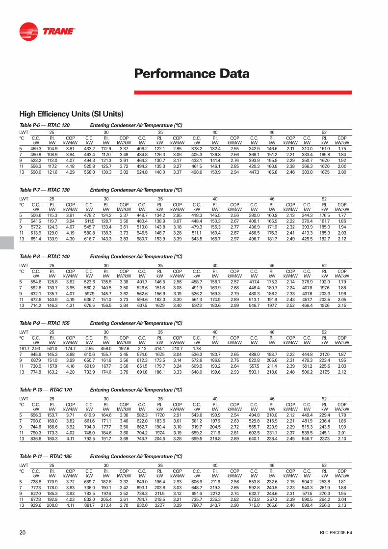
High Efficiency Units (SI Units)
Table P-6 — RTAC 120 Entering Condenser Air Temperature (°C)
LWT 25 30 35 40 46 52°C C.C. P.I. COP C.C. P.I. COP C.C. P.I. COP C.C. P.I. COP C.C. P.I. COP C.C. P.I. COP
kW kW kW/kW kW kW kW/kW kW kW kW/kW kW kW kW/kW kW kW kW/kW kW kW kW/kW5 459.3 104.9 3.81 433.2 112.9 3.37 406.2 122.1 2.95 378.2 132.4 2.55 342.9 146.6 2.11 310.0 161.0 1.757 490.9 108.9 3.94 463.4 117.0 3.49 434.8 126.3 3.06 405.3 136.8 2.66 368.1 151.2 2.21 333.4 165.8 1.849 523.2 113.0 4.07 494.3 121.3 3.61 464.2 130.7 3.17 433.1 141.4 2.76 393.9 155.9 2.29 350.7 167.0 1.9211 556.3 117.2 4.18 525.8 125.7 3.72 494.2 135.3 3.27 461.5 146.1 2.85 420.3 160.8 2.38 366.3 167.0 2.0013 590.0 121.6 4.29 558.0 130.3 3.82 524.8 140.0 3.37 490.6 150.9 2.94 447.3 165.8 2.46 383.8 167.5 2.09
Table P-7 — RTAC 130 Entering Condenser Air Temperature (°C)
LWT 25 30 35 40 46 52°C C.C. P.I. COP C.C. P.I. COP C.C. P.I. COP C.C. P.I. COP C.C. P.I. COP C.C. P.I. COP
kW kW kW/kW kW kW kW/kW kW kW kW/kW kW kW kW/kW kW kW kW/kW kW kW kW/kW5 506.6 115.3 3.81 478.2 124.2 3.37 448.7 134.2 2.95 418.3 145.5 2.56 380.0 160.9 2.13 344.3 176.5 1.777 541.5 119.7 3.94 511.5 128.7 3.50 480.4 138.9 3.07 448.4 150.3 2.67 408.1 165.9 2.22 370.4 181.7 1.869 577.2 124.3 4.07 545.7 133.4 3.61 513.0 143.8 3.18 479.3 155.3 2.77 436.9 171.0 2.32 393.9 185.0 1.9411 613.9 129.0 4.19 580.8 138.3 3.73 546.5 148.7 3.28 511.1 160.4 2.87 466.5 176.3 2.41 413.3 185.9 2.0313 651.4 133.9 4.30 616.7 143.3 3.83 580.7 153.9 3.39 543.5 165.7 2.97 496.7 181.7 2.49 425.5 182.7 2.12
Table P-8 — RTAC 140 Entering Condenser Air Temperature (°C)
LWT 25 30 35 40 46 52°C C.C. P.I. COP C.C. P.I. COP C.C. P.I. COP C.C. P.I. COP C.C. P.I. COP C.C. P.I. COP
kW kW kW/kW kW kW kW/kW kW kW kW/kW kW kW kW/kW kW kW kW/kW kW kW kW/kW5 554.6 125.8 3.82 523.6 135.5 3.38 491.7 146.5 2.96 458.7 158.7 2.57 417.4 175.3 2.14 378.9 192.0 1.797 592.8 130.7 3.95 560.2 140.5 3.50 526.6 151.6 3.08 491.9 163.9 2.68 448.4 180.7 2.24 407.8 197.6 1.889 632.1 135.7 4.07 597.9 145.7 3.62 562.6 156.9 3.19 526.2 169.3 2.79 480.3 186.2 2.33 437.6 203.3 1.9611 672.6 140.9 4.19 636.7 151.0 3.73 599.6 162.3 3.30 561.3 174.9 2.89 513.1 191.9 2.43 457.7 203.5 2.0513 714.2 146.3 4.31 676.5 156.5 3.84 637.5 167.9 3.40 597.3 180.6 2.99 546.7 197.7 2.52 466.4 197.6 2.15
Table P-9 — RTAC 155 Entering Condenser Air Temperature (°C)
LWT 25 30 35 40 46 52°C C.C. P.I. COP C.C. P.I. COP C.C. P.I. COP C.C. P.I. COP C.C. P.I. COP C.C. P.I. COP
kW kW kW/kW kW kW kW/kW kW kW kW/kW kW kW kW/kW kW kW kW/kW kW kW kW/kW161.7 2.93 501.0 174.7 2.55 456.0 192.6 2.13 414.1 210.7 1.787 645.9 145.3 3.88 610.6 155.7 3.45 574.0 167.5 3.04 536.3 180.7 2.65 489.0 198.7 2.22 444.8 217.0 1.879 687.9 151.0 3.99 650.7 161.6 3.56 612.3 173.5 3.14 572.6 186.8 2.75 522.8 205.0 2.31 476.3 223.4 1.9511 730.9 157.0 4.10 691.9 167.7 3.66 651.5 179.7 3.24 609.9 193.2 2.84 557.5 211.4 2.39 501.2 225.6 2.0313 774.8 163.2 4.20 733.9 174.0 3.76 691.6 186.1 3.33 648.0 199.6 2.93 593.1 218.0 2.48 506.2 217.5 2.12
Table P-10 — RTAC 170 Entering Condenser Air Temperature (°C)
LWT 25 30 35 40 46 52°C C.C. P.I. COP C.C. P.I. COP C.C. P.I. COP C.C. P.I. COP C.C. P.I. COP C.C. P.I. COP
kW kW kW/kW kW kW kW/kW kW kW kW/kW kW kW kW/kW kW kW kW/kW kW kW kW/kW5 656.3 153.7 3.71 619.9 164.6 3.30 582.3 177.0 2.91 543.6 190.9 2.54 494.8 210.0 2.12 449.4 229.4 1.787 700.0 160.0 3.82 661.6 171.1 3.40 622.0 183.6 3.01 581.2 197.6 2.63 529.8 216.9 2.21 481.9 236.4 1.869 744.6 166.6 3.92 704.3 177.7 3.50 662.7 190.4 3.10 619.7 204.5 2.72 565.7 223.9 2.29 515.3 243.5 1.9311 790.3 173.3 4.02 748.0 184.6 3.60 704.2 197.4 3.19 659.2 211.6 2.81 602.5 231.1 2.37 539.5 245.1 2.0113 836.8 180.3 4.11 792.5 191.7 3.69 746.7 204.5 3.28 699.5 218.8 2.89 640.1 238.4 2.45 546.7 237.3 2.10
Table P-11 — RTAC 185 Entering Condenser Air Temperature (°C)
LWT 25 30 35 40 46 52°C C.C. P.I. COP C.C. P.I. COP C.C. P.I. COP C.C. P.I. COP C.C. P.I. COP C.C. P.I. COP
kW kW kW/kW kW kW kW/kW kW kW kW/kW kW kW kW/kW kW kW kW/kW kW kW kW/kW5 728.8 170.9 3.72 689.7 182.8 3.32 649.0 196.4 2.93 606.9 211.6 2.56 553.8 232.6 2.15 504.2 253.8 1.817 777.3 178.0 3.83 736.0 190.1 3.42 693.1 203.8 3.03 648.7 219.3 2.65 592.8 240.5 2.23 540.3 261.9 1.889 827.0 185.3 3.93 783.5 197.6 3.52 738.3 211.5 3.12 691.6 227.2 2.74 632.7 248.6 2.31 577.5 270.3 1.9511 877.8 192.9 4.03 832.0 205.4 3.61 784.7 219.5 3.21 735.7 235.3 2.82 673.8 257.0 2.39 590.5 264.2 2.0413 929.6 200.8 4.11 881.7 213.4 3.70 832.0 227.7 3.29 780.7 243.7 2.90 715.8 265.6 2.46 599.4 256.0 2.13

21RLC-PRC005-E4
Performance Data
High Efficiency Units (SI Units)
Table P-12 — RTAC 200 Entering Condenser Air Temperature (°C)
LWT 25 30 35 40 46 52°C C.C. P.I. COP C.C. P.I. COP C.C. P.I. COP C.C. P.I. COP C.C. P.I. COP C.C. P.I. COP
kW kW kW/kW kW kW kW/kW kW kW kW/kW kW kW kW/kW kW kW kW/kW kW kW kW/kW5 803.3 188.3 3.73 761.2 201.3 3.33 717.3 216.1 2.95 671.8 232.6 2.59 614.2 255.4 2.17 560.1 278.4 1.837 856.9 196.2 3.84 812.3 209.4 3.44 766.0 224.4 3.05 717.9 241.2 2.68 657.1 264.3 2.26 600.0 287.8 1.919 911.8 204.4 3.94 864.8 217.8 3.53 816.0 233.0 3.14 765.4 250.2 2.76 701.3 273.7 2.33 629.6 290.6 1.9811 968.0 212.9 4.04 918.6 226.5 3.62 867.3 242.0 3.22 814.1 259.4 2.84 746.8 283.3 2.41 642.5 283.5 2.0713 1025.5 221.6 4.12 973.7 235.5 3.71 919.9 251.2 3.31 864.1 269.0 2.92 793.5 293.3 2.48 648.9 272.4 2.17
Notes :1. Ratings based on sea level altitude and evaporator fouling factor of 0.0176 m²°K/kW.2. Consult Trane representative for performance at temperatures outside of the ranges shown.3. P.I. kW = compressor power input only.4. COP = Coefficient of Performance (kW/kW). Power input includes compressors, condenser fans and control power.5. Ratings are based on an evaporator temperature drop of 6°C.6. Interpolation between points is permissible. Extrapolation is not permitted.7. Above 40°C ambient, the units will have the High-Ambient option.8. Shaded area reflects Adaptive Control™ Microprocessor control algorithms.

22 RLC-PRC005-E4
Performance Data
Low Noise Standard Units (SI Units)
Table P-13 — RTAC 140 Entering Condenser Air Temperature (°C)
LWT 25 30 35 40°C C.C. kW P.I. kW COP kW/kW C.C. kW P.I. kW COP kW/kW C.C. kW P.I. kW COP kW/kW C.C. kW P.I. kW COP kW/kW5 510.3 144.5 3.36 478.7 156.3 2.92 446.2 169.3 2.52 412.9 183.5 2.167 541.1 150.7 3.42 507.9 162.7 2.98 473.7 175.9 2.58 438.8 190.4 2.229 572.3 157.1 3.48 537.4 169.4 3.04 501.6 182.8 2.64 465.3 197.4 2.2711 603.8 163.7 3.53 567.3 176.2 3.09 529.7 189.9 2.68 491.5 204.7 2.3213 635.6 170.6 3.57 597.3 183.3 3.13 558.0 197.2 2.73 509.0 205.6 2.39
Table P-14 — RTAC 155 Entering Condenser Air Temperature (°C)
LWT 25 30 35 40°C C.C. kW P.I. kW COP kW/kW C.C. kW P.I. kW COP kW/kW C.C. kW P.I. kW COP kW/kW C.C. kW P.I. kW COP kW/kW5 560.0 159.7 3.33 525.5 172.2 2.91 490.0 186.1 2.52 453.8 201.2 2.167 593.4 166.7 3.39 557.0 179.5 2.97 519.8 193.5 2.57 481.6 208.9 2.229 627.1 173.9 3.44 588.9 186.9 3.02 549.8 201.2 2.62 509.8 216.8 2.2611 661.1 181.4 3.48 621.1 194.7 3.06 580.0 209.2 2.67 538.1 224.9 2.3113 695.3 189.1 3.52 653.4 202.6 3.10 610.5 217.3 2.71 556.8 225.9 2.38
Table P-15 — RTAC 170 Entering Condenser Air Temperature (°C)
LWT 25 30 35 40°C C.C. kW P.I. kW COP kW/kW C.C. kW P.I. kW COP kW/kW C.C. kW P.I. kW COP kW/kW C.C. kW P.I. kW COP kW/kW5 610.3 175.1 3.31 572.8 188.3 2.90 534.3 203.0 2.52 494.8 219.1 2.177 646.3 182.9 3.36 606.8 196.4 2.95 566.2 211.3 2.57 524.8 227.7 2.229 682.6 191.0 3.41 641.1 204.7 3.00 598.4 219.9 2.61 555.0 236.3 2.2611 719.1 199.4 3.45 675.6 213.3 3.04 630.9 228.6 2.65 585.5 245.3 2.3013 755.8 208.0 3.48 710.2 222.1 3.07 663.5 237.6 2.69 604.8 246.2 2.37
Table P-16 — RTAC 185 Entering Condenser Air Temperature (°C)
LWT 25 30 35 40°C C.C. kW P.I. kW COP kW/kW C.C. kW P.I. kW COP kW/kW C.C. kW P.I. kW COP kW/kW C.C. kW P.I. kW COP kW/kW5 675.9 193.4 3.32 635.4 208.0 2.91 593.7 224.3 2.53 550.9 242.1 2.197 715.5 202.1 3.37 672.8 217.1 2.96 628.9 233.6 2.58 583.8 251.7 2.239 755.4 211.1 3.42 710.6 226.4 3.01 664.4 243.3 2.62 615.2 261.0 2.2711 795.7 220.5 3.45 748.6 236.1 3.04 700.2 253.3 2.66 648.6 271.3 2.3113 836.2 230.1 3.48 787.0 246.1 3.07 736.3 263.7 2.69 668.0 271.0 2.38
Table P-17 — RTAC 200 Entering Condenser Air Temperature (°C)
LWT 25 30 35 40°C C.C. kW P.I. kW COP kW/kW C.C. kW P.I. kW COP kW/kW C.C. kW P.I. kW COP kW/kW C.C. kW P.I. kW COP kW/kW5 742.7 212.0 3.33 699.2 228.1 2.93 654.1 245.8 2.55 607.7 265.2 2.207 786.1 221.6 3.38 740.1 238.0 2.97 692.6 256.2 2.59 643.7 276.1 2.249 829.9 231.6 3.42 781.5 248.5 3.01 731.6 267.1 2.63 680.5 287.3 2.2811 874.1 242.0 3.46 823.3 259.3 3.05 771.0 278.4 2.66 717.1 299.2 2.3113 918.6 252.8 3.48 865.5 270.6 3.07 810.6 290.2 2.69 730.4 292.2 2.41
Notes :1. Ratings based on sea level altitude and evaporator fouling factor of 0.0176 m²°K/kW.2. Consult Trane representative for performance at temperatures outside of the ranges shown.3. P.I. kW = compressor power input only.4. COP = Coefficient of Performance (kW/kW). Power input includes compressors, condenser fans and control power.5. Ratings are based on an evaporator temperature drop of 6°C.6. Interpolation between points is permissible. Extrapolation is not permitted.7. Above 40°C ambient, the units will have the High-Ambient option.8. Shaded area reflects Adaptive Control™ Microprocessor control algorithms.

23RLC-PRC005-E4
Performance Data
Low Noise HE Units (SI Units)
Table P-18 — RTAC 120 Entering Condenser Air Temperature (°C)
LWT 25 30 35 40 46°C C.C. P.I. COP C.C. P.I. COP C.C. P.I. COP C.C. P.I. COP C.C. P.I. COP
kW kW kW/kW kW kW kW/kW kW kW kW/kW kW kW kW/kW kW kW kW/kW5 443.2 113.4 3.67 416.2 122.4 3.20 388.3 132.6 2.77 359.7 143.9 2.38 323.9 159.2 1.947 471.8 118.0 3.76 443.3 127.3 3.29 413.9 137.7 2.85 383.7 149.1 2.45 345.9 164.8 2.019 500.8 122.9 3.84 470.8 132.4 3.37 439.8 142.9 2.92 408.0 154.6 2.52 363.8 167.4 2.0811 530.2 128.0 3.91 498.6 137.6 3.44 466.1 148.4 2.99 432.7 160.3 2.58 376.7 166.8 2.1613.0 560.0 133.2 3.98 526.8 143.1 3.50 492.6 154.0 3.05 457.6 166.1 2.64 391.7 166.8 2.25
Table P-19 — RTAC 130 Entering Condenser Air Temperature (°C)
LWT 25 30 35 40 46°C C.C. P.I. COP C.C. P.I. COP C.C. P.I. COP C.C. P.I. COP C.C. P.I. COP
kW kW kW/kW kW kW kW/kW kW kW kW/kW kW kW kW/kW kW kW kW/kW5 489.3 124.6 3.68 459.8 134.6 3.22 429.5 145.7 2.79 398.4 158.0 2.40 359.6 174.6 1.977 520.9 129.8 3.77 489.9 139.9 3.30 458.0 151.2 2.87 425.2 163.7 2.47 384.2 180.5 2.039 553.2 135.2 3.85 520.5 145.5 3.38 486.9 157.0 2.94 452.4 169.6 2.54 406.1 184.9 2.1011 585.9 140.7 3.93 551.6 151.3 3.46 516.3 162.9 3.01 480.0 175.8 2.61 422.9 185.7 2.1813 619.1 146.5 4.00 583.1 157.2 3.52 546.0 169.0 3.08 508.0 182.0 2.67 434.8 182.8 2.27
Table P-20 — RTAC 140 Entering Condenser Air Temperature (°C)
LWT 25 30 35 40 46°C C.C. P.I. COP C.C. P.I. COP C.C. P.I. COP C.C. P.I. COP C.C. P.I. COP
kW kW kW/kW kW kW kW/kW kW kW kW/kW kW kW kW/kW kW kW kW/kW5 535.9 136.0 3.69 503.9 146.8 3.23 471.1 158.9 2.80 437.5 172.1 2.41 395.5 189.9 1.997 570.7 141.7 3.78 537.1 152.7 3.32 502.5 164.9 2.89 467.1 178.3 2.49 422.9 196.4 2.069 606.3 147.5 3.87 570.9 158.7 3.40 534.5 171.1 2.96 497.3 184.7 2.56 450.9 202.9 2.1311 642.5 153.6 3.95 605.3 165.0 3.47 567.1 177.6 3.04 527.9 191.3 2.63 468.5 203.5 2.2013 679.4 159.9 4.02 640.3 171.5 3.54 600.2 184.2 3.10 559.0 198.1 2.70 476.8 197.6 2.31
Table P-21 — RTAC 155 Entering Condenser Air Temperature (°C)
LWT 25 30 35 40 46°C C.C. P.I. COP C.C. P.I. COP C.C. P.I. COP C.C. P.I. COP C.C. P.I. COP
kW kW kW/kW kW kW kW/kW kW kW kW/kW kW kW kW/kW kW kW kW/kW5 584.6 150.5 3.64 550.0 162.0 3.20 514.3 174.9 2.78 477.8 189.1 2.40 432.1 208.3 1.987 621.9 156.9 3.73 585.3 168.6 3.28 547.8 181.7 2.86 509.3 196.1 2.47 461.2 215.5 2.049 659.8 163.5 3.80 621.3 175.4 3.35 581.8 188.7 2.93 541.4 203.3 2.54 491.1 222.9 2.1111 698.3 170.4 3.87 657.9 182.5 3.42 616.4 195.9 2.99 573.9 210.6 2.60 511.6 224.4 2.1813 737.3 177.5 3.93 695.0 189.7 3.48 651.5 203.3 3.05 606.9 218.2 2.66 519.4 217.6 2.28
Table P-22 — RTAC 170 Entering Condenser Air Temperature (°C)
LWT 25 30 35 40 46°C C.C. P.I. COP C.C. P.I. COP C.C. P.I. COP C.C. P.I. COP C.C. P.I. COP
kW kW kW/kW kW kW kW/kW kW kW kW/kW kW kW kW/kW kW kW kW/kW5 634.0 165.0 3.60 596.5 177.3 3.17 557.9 191.0 2.76 518.4 206.2 2.39 468.9 226.8 1.977 673.7 172.2 3.68 634.2 184.7 3.24 593.6 198.6 2.83 551.9 213.9 2.45 499.8 234.8 2.039 714.1 179.6 3.75 672.5 192.3 3.31 629.7 206.4 2.90 585.9 221.9 2.52 531.3 242.8 2.0911 755.0 187.3 3.81 711.3 200.1 3.37 666.4 214.4 2.96 620.4 230.1 2.57 551.4 243.6 2.1713 796.3 195.2 3.86 750.5 208.2 3.42 703.5 222.6 3.01 655.3 238.4 2.63 561.1 237.4 2.26
Table P-23 — RTAC 185 Entering Condenser Air Temperature (°C)
LWT 25 30 35 40 46°C C.C. P.I. COP C.C. P.I. COP C.C. P.I. COP C.C. P.I. COP C.C. P.I. COP
kW kW kW/kW kW kW kW/kW kW kW kW/kW kW kW kW/kW kW kW kW/kW5 704.3 183.7 3.60 663.7 197.1 3.18 621.7 212.2 2.78 578.6 228.9 2.40 524.5 251.5 1.997 748.4 191.7 3.68 705.5 205.5 3.25 661.2 220.8 2.84 615.7 237.8 2.47 558.6 260.8 2.059 793.2 200.1 3.74 747.9 214.2 3.31 701.3 229.8 2.90 653.4 247.0 2.52 590.1 267.9 2.1111 838.5 208.9 3.80 791.0 223.1 3.37 742.0 239.0 2.96 691.7 256.6 2.58 605.9 264.3 2.1913 884.5 217.8 3.85 834.7 232.4 3.42 783.3 248.6 3.01 730.6 266.4 2.63 614.9 256.3 2.29

24 RLC-PRC005-E4
Performance Data
Low Noise HE Units (SI Units)
Table P-24 — RTAC 200 Entering Condenser Air Temperature (°C)
LWT 25 30 35 40 46°C C.C. P.I. COP C.C. P.I. COP C.C. P.I. COP C.C. P.I. COP C.C. P.I. COP
kW kW kW/kW kW kW kW/kW kW kW kW/kW kW kW kW/kW kW kW kW/kW5 776.4 202.6 3.61 732.4 217.3 3.19 686.9 233.7 2.79 640.1 251.9 2.42 581.1 276.6 2.017 824.9 211.6 3.68 778.4 226.6 3.25 730.3 243.4 2.85 680.8 262.0 2.48 618.6 287.2 2.069 874.3 221.0 3.74 825.2 236.4 3.31 774.5 253.6 2.91 722.4 272.5 2.53 644.6 289.6 2.1311 924.4 230.8 3.80 872.8 246.5 3.37 819.5 264.1 2.96 764.6 283.5 2.58 654.7 281.3 2.2313 975.2 240.9 3.85 921.0 257.1 3.42 865.1 275.1 3.01 807.5 294.9 2.63 665.5 272.6 2.33
Notes :1. Ratings based on sea level altitude and evaporator fouling factor of 0.0176 m²°K/kW.2. Consult Trane representative for performance at temperatures outside of the ranges shown.3. P.I. kW = compressor power input only.4. COP = Coefficient of Performance (kW/kW). Power input includes compressors, condenser fans and control power.5. Ratings are based on an evaporator temperature drop of 6°C.6. Interpolation between points is permissible. Extrapolation is not permitted.7. Above 40°C ambient, the units will have the High-Ambient option.8. Shaded area reflects Adaptive Control™ Microprocessor control algorithms.

25RLC-PRC005-E4
Performance Data
Standard Units (English Units)
Table P-25 — RTAC 140 Entering Condenser Air Temperature (°F)
LWT 77 86 95 104 115 122°F C.C. P.I. EER C.C. P.I. EER C.C. P.I. EER C.C. P.I. EER C.C. P.I. EER C.C. P.I. EER
Ton kW Ton kW Ton kW Ton kW Ton kW Ton kW41 152.5 131.3 12.45 143.8 141.8 10.96 134.8 153.5 9.56 125.6 166.5 8.27 114.0 184.0 6.85 106.4 196.1 6.0344 160.8 135.5 12.75 151.7 146.2 11.24 142.4 158.1 9.83 132.7 171.2 8.52 120.6 188.9 7.08 112.8 201.1 6.2445 163.6 137.0 12.85 154.4 147.7 11.34 144.9 159.6 9.92 135.1 172.8 8.60 122.9 190.5 7.15 114.3 201.5 6.3146 166.4 138.5 12.95 157.1 149.2 11.43 147.5 161.2 10.00 137.6 174.4 8.68 125.1 192.2 7.22 115.0 200.1 6.3948 172.0 141.4 13.14 162.5 152.3 11.61 152.6 164.3 10.17 142.5 177.6 8.84 129.7 195.5 7.37 116.3 197.4 6.55
Table P-26 — RTAC 155 Entering Condenser Air Temperature (°F)
LWT 77 86 95 104 115 122°F C.C. P.I. EER C.C. P.I. EER C.C. P.I. EER C.C. P.I. EER C.C. P.I. EER C.C. P.I. EER
Ton kW Ton kW Ton kW Ton kW Ton kW Ton kW41 167.2 145.8 12.28 157.7 156.9 10.84 147.9 169.4 9.49 137.8 183.2 8.24 125.1 201.9 6.84 116.9 214.9 6.0344 176.2 150.7 12.56 166.3 162.0 11.11 156.0 174.6 9.74 145.5 188.5 8.47 132.3 207.4 7.05 123.7 220.6 6.2345 179.2 152.4 12.65 169.1 163.7 11.20 158.8 176.3 9.83 148.1 190.3 8.55 134.7 209.3 7.12 125.4 221.2 6.3046 182.2 154.1 12.74 172.1 165.4 11.28 161.6 178.1 9.91 150.7 192.1 8.62 137.2 211.2 7.19 126.2 220.0 6.3848 188.3 157.5 12.91 177.9 168.9 11.44 167.1 181.7 10.06 156.0 195.8 8.77 142.0 214.9 7.33 127.9 217.6 6.53
Table P-27 — RTAC 170 Entering Condenser Air Temperature (°F)
LWT 77 86 95 104 115 122°F C.C. P.I. EER C.C. P.I. EER C.C. P.I. EER C.C. P.I. EER C.C. P.I. EER C.C. P.I. EER
Ton kW Ton kW Ton kW Ton kW Ton kW Ton kW41 182.1 160.5 12.14 171.8 172.2 10.75 161.1 185.4 9.44 150.2 200.0 8.21 136.4 220.0 6.83 127.4 233.9 6.0444 191.8 166.1 12.40 181.0 177.9 11.00 169.9 191.2 9.67 158.4 206.0 8.43 144.1 226.1 7.04 134.7 240.1 6.2345 195.0 168.0 12.48 184.1 179.9 11.08 172.8 193.2 9.75 161.2 208.0 8.50 146.6 228.2 7.10 136.5 241.0 6.2946 198.3 170.0 12.56 187.2 181.9 11.16 175.8 195.2 9.82 164.0 210.1 8.57 149.3 230.3 7.17 137.5 240.0 6.3648 204.9 173.8 12.72 193.5 185.8 11.31 181.8 199.3 9.97 169.7 214.2 8.71 154.5 234.5 7.30 139.5 237.9 6.51
Table P-28 — RTAC 185 Entering Condenser Air Temperature (°F)
LWT 77 86 95 104 115 122°F C.C. P.I. EER C.C. P.I. EER C.C. P.I. EER C.C. P.I. EER C.C. P.I. EER C.C. P.I. EER
Ton kW Ton kW Ton kW Ton kW Ton kW Ton kW41 201.4 177.3 12.17 190.4 190.2 10.80 178.9 204.6 9.50 167.1 220.8 8.28 152.1 242.8 6.91 142.4 258.0 6.1144 212.1 183.4 12.43 200.5 196.5 11.04 188.6 211.2 9.73 176.2 227.5 8.49 160.6 249.8 7.11 148.3 260.8 6.3145 215.6 185.5 12.51 203.9 198.6 11.12 191.8 213.4 9.80 179.3 229.8 8.56 163.4 252.1 7.17 150.0 260.8 6.3846 219.3 187.6 12.59 207.4 200.8 11.20 195.1 215.7 9.88 182.4 232.1 8.63 166.3 254.6 7.23 151.0 259.6 6.4548 226.5 191.9 12.74 214.3 205.2 11.35 201.6 220.2 10.02 188.6 236.8 8.76 172.1 259.4 7.35 153.1 257.1 6.60
Table P-29 — RTAC 200 Entering Condenser Air Temperature (°F)
LWT 77 86 95 104 115 122°F C.C. P.I. EER C.C. P.I. EER C.C. P.I. EER C.C. P.I. EER C.C. P.I. EER C.C. P.I. EER
Ton kW Ton kW Ton kW Ton kW Ton kW Ton kW41 221.2 194.3 12.21 209.4 208.3 10.85 197.1 224.2 9.56 184.3 241.8 8.34 168.1 265.7 6.98 157.5 282.4 6.1844 232.9 201.0 12.46 220.5 215.3 11.09 207.6 231.4 9.78 194.3 249.3 8.55 177.3 273.7 7.17 163.8 285.0 6.3845 236.8 203.3 12.54 224.2 217.7 11.17 211.2 233.9 9.85 197.6 251.9 8.62 180.5 276.3 7.23 165.3 284.5 6.4546 240.7 205.7 12.62 228.0 220.1 11.24 214.8 236.4 9.93 201.0 254.5 8.69 183.6 279.1 7.29 166.0 282.1 6.5348 248.6 210.3 12.77 235.6 225.0 11.39 221.9 241.4 10.06 207.8 259.7 8.81 189.9 284.6 7.40 167.3 277.2 6.68
Notes :1. Ratings based on sea level altitude and evaporator fouling factor of 0.0176 m²°K/kW.2. Consult Trane representative for performance at temperatures outside of the ranges shown.3. P.I. kW = compressor power input only.4. COP = Coefficient of Performance (kW/kW). Power input includes compressors, condenser fans and control power.5. Ratings are based on an evaporator temperature drop of 6°C.6. Interpolation between points is permissible. Extrapolation is not permitted.7. Above 40°C ambient, the units will have the High-Ambient option.8. Shaded area reflects Adaptive Control™ Microprocessor control algorithms.

26 RLC-PRC005-E4
Performance Data
High Efficiency Units (English Units)
Table P-30 — RTAC 120 Entering Condenser Air Temperature (°F)
LWT 77 86 95 104 115 122°F C.C. P.I. EER C.C. P.I. EER C.C. P.I. EER C.C. P.I. EER C.C. P.I. EER C.C. P.I. EER
Ton kW EER Ton kW EER Ton kW EER Ton kW EER Ton kW EER Ton kW EER
41 130.6 104.9 12.99 123.2 112.9 11.49 115.5 122.1 10.06 107.6 132.4 8.71 97.5 146.6 7.21 88.1 161.0 1.7244 138.1 108.2 13.37 130.4 116.3 11.84 122.3 125.6 10.38 114.0 136.1 9.01 103.5 150.4 7.48 93.7 165.0 6.2245 140.6 109.3 13.49 132.8 117.5 11.96 124.6 126.8 10.49 116.2 137.3 9.11 105.5 151.7 7.56 95.3 165.9 6.3046 143.2 110.5 13.62 135.2 118.7 12.07 126.9 128.0 10.59 118.3 138.6 9.20 107.5 153.0 7.65 96.7 166.3 6.3848 148.3 112.7 13.85 140.1 121.0 12.29 131.6 130.5 10.80 122.7 141.1 9.39 111.6 155.7 7.81 99.4 166.9 6.53
Table P-31 — RTAC 130 Entering Condenser Air Temperature (°F)
LWT 77 86 95 104 115 122°F C.C. P.I. EER C.C. P.I. EER C.C. P.I. EER C.C. P.I. EER C.C. P.I. EER C.C. P.I. EER
Ton kW EER Ton kW EER Ton kW EER Ton kW EER Ton kW EER Ton kW EER
41 144.1 115.3 13.01 136.0 124.2 11.51 127.6 134.2 10.08 119.0 145.5 8.75 108.1 160.9 7.27 97.9 176.5 1.7444 152.4 119.0 13.38 143.9 128.0 11.86 135.1 138.1 10.41 126.1 149.5 9.05 114.7 165.1 7.54 104.1 180.8 6.3045 155.1 120.2 13.51 146.6 129.2 11.98 137.7 139.5 10.52 128.5 150.9 9.15 117.0 166.5 7.62 106.1 182.0 6.3846 158.0 121.5 13.63 149.3 130.5 12.09 140.2 140.8 10.62 131.0 152.2 9.25 119.2 167.9 7.71 107.9 183.0 6.4648 163.6 124.0 13.86 154.7 133.2 12.31 145.4 143.5 10.83 135.8 155.0 9.44 123.8 170.8 7.89 111.6 184.8 6.62
Table P-32 — RTAC 140 Entering Condenser Air Temperature (°F)
LWT 77 86 95 104 115 122°F C.C. P.I. EER C.C. P.I. EER C.C. P.I. EER C.C. P.I. EER C.C. P.I. EER C.C. P.I. EER
Ton kW EER Ton kW EER Ton kW EER Ton kW EER Ton kW EER Ton kW EER
41 157.7 125.8 13.03 148.9 135.5 11.53 139.8 146.5 10.11 130.5 158.7 8.79 118.7 175.3 7.31 107.7 192.0 6.1144 166.8 129.8 13.40 157.6 139.7 11.88 148.1 150.7 10.44 138.3 163.0 9.10 126.1 179.8 7.59 114.6 196.6 6.3645 169.8 131.2 13.52 160.5 141.1 12.00 150.9 152.2 10.55 141.0 164.5 9.20 128.5 181.3 7.68 116.9 198.2 6.4446 172.9 132.6 13.64 163.5 142.5 12.11 153.7 153.6 10.66 143.7 166.0 9.30 131.1 182.8 7.77 119.3 199.8 6.5348 179.2 135.4 13.88 169.5 145.4 12.33 159.4 156.6 10.87 149.1 169.0 9.49 136.1 185.9 7.95 124.0 203.0 6.69
Table P-33 — RTAC 155 Entering Condenser Air Temperature (°F)
LWT 77 86 95 104 115 122°F C.C. P.I. EER C.C. P.I. EER C.C. P.I. EER C.C. P.I. EER C.C. P.I. EER C.C. P.I. EER
Ton kW EER Ton kW EER Ton kW EER Ton kW EER Ton kW EER Ton kW EER
41 172.1 139.7 12.82 162.5 150.0 11.38 152.7 161.7 10.01 142.5 174.7 8.72 129.7 192.6 7.27 117.7 210.7 6.0944 181.8 144.3 13.16 171.8 154.8 11.70 161.5 166.5 10.31 150.9 179.7 9.00 137.5 197.7 7.53 125.0 215.9 6.3245 185.0 145.9 13.27 174.9 156.4 11.81 164.5 168.2 10.41 153.7 181.4 9.09 140.1 199.4 7.62 127.5 217.7 6.4046 188.4 147.5 13.38 178.1 158.0 11.91 167.5 169.9 10.51 156.6 183.1 9.19 142.8 201.2 7.70 130.0 219.4 6.4848 195.0 150.7 13.59 184.4 161.3 12.12 173.5 173.2 10.70 162.3 186.5 9.37 148.2 204.7 7.87 134.9 223.0 6.63
Table P-34 — RTAC 170 Entering Condenser Air Temperature (°F)
LWT 77 86 95 104 115 122°F C.C. P.I. EER C.C. P.I. EER C.C. P.I. EER C.C. P.I. EER C.C. P.I. EER C.C. P.I. EER
Ton kW EER Ton kW EER Ton kW EER Ton kW EER Ton kW EER Ton kW EER
41 186.7 153.7 12.66 176.3 164.6 11.26 165.6 177.0 9.92 154.6 190.9 8.66 140.7 210.0 7.24 127.8 229.4 6.0744 197.0 159.0 12.97 186.2 170.0 11.56 175.0 182.5 10.21 163.5 196.5 8.93 149.0 215.7 7.48 135.5 235.2 6.2945 200.5 160.7 13.07 189.5 171.8 11.66 178.2 184.3 10.30 166.5 198.4 9.02 151.8 217.7 7.56 138.1 237.2 6.3646 204.0 162.6 13.17 192.9 173.6 11.76 181.4 186.2 10.39 169.6 200.3 9.10 154.7 219.6 7.64 140.7 239.1 6.4448 211.1 166.2 13.37 199.6 177.4 11.94 187.8 190.0 10.57 175.6 204.1 9.27 160.3 223.5 7.80 146.0 243.1 6.58
Table P-35 — RTAC 185 Entering Condenser Air Temperature (°F)
LWT 77 86 95 104 115 122°F C.C. P.I. EER C.C. P.I. EER C.C. P.I. EER C.C. P.I. EER C.C. P.I. EER C.C. P.I. EER
Ton kW EER Ton kW EER Ton kW EER Ton kW EER Ton kW EER Ton kW EER
41 207.3 170.9 12.69 196.2 182.8 11.32 184.6 196.4 10.00 172.6 211.6 8.75 157.5 232.6 7.34 143.4 253.8 6.1744 218.8 176.8 13.00 207.1 188.9 11.61 195.0 202.6 10.28 182.5 218.0 9.01 166.7 239.1 7.57 151.9 260.6 6.3845 222.7 178.8 13.10 210.8 190.9 11.71 198.5 204.7 10.37 185.9 220.2 9.09 169.9 241.4 7.65 154.8 262.9 6.4546 226.6 180.8 13.20 214.6 193.0 11.80 202.1 206.8 10.46 189.3 222.4 9.18 173.0 243.6 7.72 157.8 265.2 6.5248 234.4 184.9 13.39 222.1 197.2 11.99 209.3 211.1 10.63 196.0 226.7 9.34 179.3 248.1 7.87 163.6 269.9 6.66

27RLC-PRC005-E4
Performance Data
Table P-36 — RTAC 200 Entering Condenser Air Temperature (°F)
LWT 77 86 95 104 115 122°F C.C. P.I. EER C.C. P.I. EER C.C. P.I. EER C.C. P.I. EER C.C. P.I. EER C.C. P.I. EER
Ton kW EER Ton kW EER Ton kW EER Ton kW EER Ton kW EER Ton kW EER
232.6 8.83 174.7 255.4 7.42 159.3 278.4 6.2644 241.2 194.9 13.04 228.6 208.1 11.67 215.5 223.0 10.34 202.0 239.8 9.08 184.9 262.8 7.65 168.7 286.2 6.4645 245.5 197.1 13.14 232.7 210.3 11.76 219.4 225.4 10.43 205.7 242.2 9.17 188.3 265.4 7.73 171.5 288.1 6.5346 249.8 199.4 13.24 236.8 212.7 11.86 223.4 227.8 10.52 209.4 244.7 9.25 191.8 268.0 7.80 173.9 288.9 6.6148 258.5 204.0 13.43 245.1 217.3 12.04 231.3 232.6 10.69 216.9 249.7 9.41 198.8 273.1 7.95 178.6 290.4 6.75
Notes :1. Ratings based on sea level altitude and evaporator fouling factor of 0.0176 m²°K/kW.2. Consult Trane representative for performance at temperatures outside of the ranges shown.3. P.I. kW = compressor power input only.4. COP = Coefficient of Performance (kW/kW). Power input includes compressors, condenser fans and control power.5. Ratings are based on an evaporator temperature drop of 6°C.6. Interpolation between points is permissible. Extrapolation is not permitted.7. Above 40°C ambient, the units will have the High-Ambient option.8. Shaded area reflects Adaptive Control™ Microprocessor control algorithms.

28 RLC-PRC005-E4
Performance Data
Low Noise Standard Units (English Units)
Table P-37 — RTAC 140 Entering Condenser Air Temperature (°F)
LWT 77 86 95 104°F C.C.Ton P.I. kW EER C.C.Ton P.I. kW EER C.C.Ton P.I. kW EER C.C.Ton P.I. kW EER41 145.1 144.5 11.46 136.1 156.3 9.97 126.9 169.3 8.61 117.4 183.5 7.3844 152.4 149.7 11.64 143.1 161.7 10.15 133.4 174.8 8.78 123.5 189.2 7.5445 154.9 151.4 11.70 145.4 163.5 10.20 135.6 176.7 8.83 125.6 191.1 7.5946 157.3 153.2 11.75 147.7 165.3 10.26 137.8 178.6 8.89 127.7 193.1 7.6448 162.3 156.7 11.86 152.4 169.0 10.36 142.2 182.4 8.98 131.9 197.0 7.74
Table P-38 — RTAC 155 Entering Condenser Air Temperature (°F)
LWT 77 86 95 104°F C.C.Ton P.I. kW EER C.C.Ton P.I. kW EER C.C.Ton P.I. kW EER C.C.Ton P.I. kW EER41 159.3 159.7 11.37 149.5 172.2 9.93 139.4 186.1 8.60 129.0 201.2 7.3944 167.2 165.5 11.54 156.9 178.3 10.09 146.4 192.3 8.76 135.6 207.7 7.5445 169.8 167.5 11.59 159.4 180.3 10.14 148.8 194.4 8.81 137.8 209.8 7.5846 172.5 169.5 11.64 162.0 182.4 10.19 151.2 196.5 8.85 140.1 212.0 7.6348 177.8 173.5 11.73 167.0 186.5 10.28 155.9 200.8 8.94 144.5 216.3 7.72
Table P-39 — RTAC 170 Entering Condenser Air Temperature (°F)
LWT 77 86 95 104°F C.C.Ton P.I. kW EER C.C.Ton P.I. kW EER C.C.Ton P.I. kW EER C.C.Ton P.I. kW EER41 173.6 175.1 11.30 162.9 188.3 9.90 152.0 203.0 8.59 140.7 219.1 7.4044 182.1 181.6 11.45 171.0 195.0 10.05 159.5 209.9 8.74 147.8 226.2 7.5345 185.0 183.8 11.50 173.7 197.3 10.09 162.1 212.3 8.78 150.2 228.6 7.5846 187.8 186.0 11.54 176.4 199.6 10.13 164.6 214.6 8.82 152.6 231.0 7.6248 193.6 190.6 11.63 181.8 204.3 10.22 169.7 219.4 8.91 157.3 235.8 7.71
Table P-40 — RTAC 185 Entering Condenser Air Temperature (°F)
LWT 77 86 95 104°F C.C.Ton P.I. kW EER C.C.Ton P.I. kW EER C.C.Ton P.I. kW EER C.C.Ton P.I. kW EER41 192.2 193.4 11.34 180.7 208.0 9.94 168.9 224.3 8.65 156.7 242.1 7.4644 201.6 200.6 11.48 189.6 215.6 10.08 177.2 232.0 8.78 164.4 250.1 7.5945 204.7 203.1 11.53 192.6 218.1 10.13 180.0 234.7 8.83 167.0 252.8 7.6346 207.9 205.6 11.57 195.5 220.7 10.17 182.8 237.4 8.87 169.5 255.3 7.6648 214.2 210.6 11.65 201.5 225.9 10.25 188.4 242.7 8.94 174.4 260.5 7.74
Table P-41 — RTAC 200 Entering Condenser Air Temperature (°F)
LWT 77 86 95 104°F C.C.Ton P.I. kW EER C.C.Ton P.I. kW EER C.C.Ton P.I. kW EER C.C.Ton P.I. kW EER41 211.2 212.0 11.37 198.9 228.1 9.99 186.0 245.8 8.70 172.8 265.2 7.5144 221.5 220.0 11.51 208.6 236.4 10.12 195.2 254.5 8.83 181.3 274.3 7.6345 225.0 222.7 11.55 211.8 239.2 10.16 198.2 257.4 8.87 184.2 277.3 7.6746 228.4 225.5 11.59 215.1 242.1 10.20 201.3 260.4 8.90 187.1 280.4 7.7148 235.3 231.0 11.67 221.6 247.9 10.28 207.5 266.5 8.98 192.9 286.7 7.78
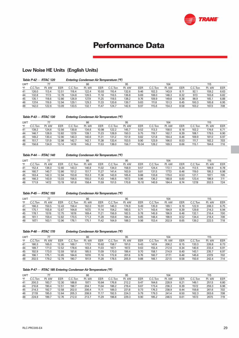
Notes :1. Ratings based on sea level altitude and evaporator fouling factor of 0.0176 m²°K/kW.2. Consult Trane representative for performance at temperatures outside of the ranges shown.3. P.I. kW = compressor power input only.4. COP = Coefficient of Performance (kW/kW). Power input includes compressors, condenser fans and control power.5. Ratings are based on an evaporator temperature drop of 6°C.6. Interpolation between points is permissible. Extrapolation is not permitted.7. Above 40°C ambient, the units will have the High-Ambient option.8. Shaded area reflects Adaptive Control™ Microprocessor control algorithms.
29RLC-PRC005-E4
Performance Data
Low Noise HE Units (English Units)
Table P-42 — RTAC 120 Entering Condenser Air Temperature (°F)
LWT 77 86 95 104 115°F C.C.Ton P.I. kW EER C.C.Ton P.I. kW EER C.C.Ton P.I. kW EER C.C.Ton P.I. kW EER C.C.Ton P.I. kW EER41 126.0 113.4 12.51 118.4 122.4 10.93 110.4 132.6 9.46 102.3 143.9 8.11 92.1 159.2 6.6344 132.8 117.3 12.78 124.8 126.5 11.18 116.5 136.8 9.69 108.0 148.3 8.32 97.3 163.8 6.8245 135.1 118.6 12.86 126.9 127.9 11.25 118.5 138.2 9.76 109.9 149.8 8.38 98.9 165.1 6.8846 137.4 119.9 12.94 129.1 129.3 11.33 120.6 139.7 9.83 111.8 151.3 8.45 100.3 165.8 6.9548 142.0 122.6 13.09 133.5 132.1 11.47 124.7 142.6 9.97 115.6 154.3 8.58 103.2 167.3 7.08
Table P-43 — RTAC 130 Entering Condenser Air Temperature (°F)
LWT 77 86 95 104 115°F C.C.Ton P.I. kW EER C.C.Ton P.I. kW EER C.C.Ton P.I. kW EER C.C.Ton P.I. kW EER C.C.Ton P.I. kW EER41 139.2 124.6 12.56 130.8 134.6 10.98 122.2 145.7 9.52 113.3 158.0 8.18 102.2 174.6 6.7144 146.7 128.9 12.82 137.9 139.1 11.23 128.9 150.3 9.75 119.7 162.7 8.39 108.1 179.5 6.9045 149.2 130.4 12.90 140.3 140.6 11.31 131.2 151.9 9.82 121.8 164.4 8.46 109.9 181.0 6.9746 151.7 131.9 12.98 142.7 142.1 11.38 133.4 153.5 9.90 123.9 166.0 8.53 111.7 182.2 7.0348 156.8 134.9 13.14 147.6 145.2 11.53 138.0 156.7 10.04 128.2 169.3 8.66 115.1 184.6 7.16
Table P-44 — RTAC 140 Entering Condenser Air Temperature (°F)
LWT 77 86 95 104 115°F C.C.Ton P.I. kW EER C.C.Ton P.I. kW EER C.C.Ton P.I. kW EER C.C.Ton P.I. kW EER C.C.Ton P.I. kW EER41 152.4 136.0 12.60 143.3 146.8 11.02 134.0 158.9 9.57 124.4 172.1 8.24 112.5 189.9 6.7844 160.7 140.7 12.86 151.2 151.7 11.27 141.4 163.9 9.81 131.5 177.3 8.46 119.0 195.3 6.9845 163.4 142.3 12.94 153.8 153.3 11.36 143.9 165.6 9.88 133.8 179.0 8.53 121.1 197.1 7.0546 166.3 143.9 13.03 156.5 155.0 11.43 146.5 167.3 9.96 136.2 180.8 8.60 123.4 198.9 7.1148 171.9 147.2 13.19 161.8 158.4 11.59 151.5 170.8 10.10 140.9 184.4 8.74 127.8 202.5 7.24
Table P-45 — RTAC 155 Entering Condenser Air Temperature (°F)
LWT 77 86 95 104 115°F C.C.Ton P.I. kW EER C.C.Ton P.I. kW EER C.C.Ton P.I. kW EER C.C.Ton P.I. kW EER C.C.Ton P.I. kW EER41 166.3 150.5 12.43 156.4 162.0 10.91 146.3 174.9 9.49 135.9 189.1 8.19 122.9 208.3 6.7544 175.1 155.8 12.67 164.8 167.5 11.14 154.2 180.5 9.71 143.4 194.9 8.39 129.8 214.3 6.9445 178.1 157.6 12.75 167.6 169.4 11.21 156.9 182.5 9.78 145.9 196.9 8.46 132.1 216.4 7.0046 181.1 159.4 12.82 170.5 171.3 11.28 159.6 184.4 9.85 148.4 198.9 8.52 134.4 218.4 7.0648 187.1 163.1 12.96 176.1 175.1 11.42 164.9 188.3 9.98 153.4 202.9 8.65 139.2 222.5 7.18
Table P-46 — RTAC 170 Entering Condenser Air Temperature (°F)
LWT 77 86 95 104 115°F C.C.Ton P.I. kW EER C.C.Ton P.I. kW EER C.C.Ton P.I. kW EER C.C.Ton P.I. kW EER C.C.Ton P.I. kW EER41 180.3 165.0 12.30 169.7 177.3 10.82 158.7 191.0 9.43 147.4 206.2 8.15 133.3 226.8 6.7344 189.7 171.0 12.52 178.6 183.4 11.03 167.1 197.3 9.63 155.4 212.6 8.34 140.6 233.4 6.9145 192.9 173.0 12.59 181.6 185.5 11.09 170.0 199.4 9.70 158.1 214.9 8.40 143.1 235.7 6.9746 196.1 175.1 12.65 184.6 187.6 11.16 172.8 201.6 9.76 160.7 217.1 8.46 145.6 237.9 7.0248 202.5 179.2 12.78 190.7 191.9 11.28 178.5 205.9 9.88 166.1 221.5 8.58 150.6 242.4 7.14
Table P-47 — RTAC 185 Entering Condenser Air Temperature (°F)
LWT 77 86 95 104 115°F C.C.Ton P.I. kW EER C.C.Ton P.I. kW EER C.C.Ton P.I. kW EER C.C.Ton P.I. kW EER C.C.Ton P.I. kW EER41 200.3 183.7 12.30 188.8 197.1 10.84 176.8 212.2 9.47 164.6 228.9 8.21 149.1 251.5 6.8044 210.8 190.4 12.51 198.7 204.1 11.04 186.2 219.4 9.67 173.4 236.3 8.39 157.2 259.3 6.9645 214.3 192.7 12.58 202.0 206.4 11.11 189.3 221.8 9.73 176.3 238.9 8.44 159.8 261.6 7.0246 217.8 195.0 12.64 205.3 208.9 11.17 192.5 224.3 9.79 179.3 241.4 8.50 162.3 263.6 7.0848 224.9 199.7 12.76 212.0 213.7 11.29 198.8 229.3 9.90 185.2 246.5 8.61 167.3 267.5 7.19

30 RLC-PRC005-E4
Performance Data
Table P-48 — RTAC 200 Entering Condenser Air Temperature (°F)
LWT 77 86 95 104 115°F C.C.Ton P.I. kW EER C.C.Ton P.I. kW EER C.C.Ton P.I. kW EER C.C.Ton P.I. kW EER C.C.Ton P.I. kW EER41 220.8 202.6 12.32 208.3 217.3 10.87 195.4 233.7 9.52 182.0 251.9 8.26 165.2 276.6 6.8644 232.3 210.1 12.52 219.2 225.1 11.07 205.7 241.8 9.70 191.7 260.3 8.43 174.1 285.4 7.0145 236.2 212.6 12.58 222.9 227.7 11.13 209.1 244.6 9.76 195.0 263.2 8.48 176.7 287.4 7.0746 240.1 215.3 12.64 226.6 230.4 11.19 212.6 247.4 9.81 198.2 266.1 8.53 178.8 288.1 7.1448 247.9 220.5 12.76 234.0 235.8 11.30 219.6 253.0 9.92 204.8 272.0 8.64 182.9 289.5 7.27
Notes :1. Ratings based on sea level altitude and evaporator fouling factor of 0.0176 m²°K/kW.2. Consult Trane representative for performance at temperatures outside of the ranges shown.3. P.I. kW = compressor power input only.4. COP = Coefficient of Performance (kW/kW). Power input includes compressor, condenser fans and control power.5. Ratings are based on an evaporator temperature drop of 6°C.6. Interpolation between points is permissible. Extrapolation is not permitted.7. Above 40°C ambient, the units will have the High-Ambient option.8. Shaded area reflects Adaptive Control Microprocessor control algorithms.

31RLC-PRC005-E4
Performance Data
SI Units English Units
Table P-49 — ARI Part-Load Values RTAC Standard Table P-51 — ARI Part-Load Values RTAC Standard
(along with ARI 550/590-98) (along with ARI 550/590-98)
Unit % Load kW cooling P.I. kW COP (kW/kW) IPLV (kW/kW) Unit % Load tons P.I. kW EER IPLV 140 100 505.9 159.0 2.90 4.09 140 100 143.9 159.0 9.88 13.95
75 372.0 85.8 3.67 75 105.8 85.8 12.5150 247.9 47.3 4.47 50 70.5 47.3 15.2425 124.1 21.0 4.25 25 35.3 21.0 14.51
155 100 554.3 175.6 2.87 3.98 155 100 157.6 175.6 9.79 13.5975 407.6 94.7 3.63 75 115.9 94.7 12.3950 271.9 52.2 4.36 50 77.3 52.2 14.8925 135.7 24.8 3.89 25 38.6 24.8 13.29
170 100 603.4 192.4 2.85 3.98 170 100 171.6 192.4 9.72 13.5875 443.8 103.7 3.60 75 126.2 103.7 12.2950 295.8 58.4 4.32 50 84.1 58.4 14.7425 148.1 26.0 4.11 25 42.1 26.0 14.02
185 100 669.7 212.5 2.86 3.98 185 100 190.4 212.5 9.77 13.6075 491.7 114.6 3.62 75 139.8 114.6 12.3450 328.1 62.6 4.40 50 93.3 62.6 15.0225 164.2 31.1 3.81 25 46.7 31.1 13.00
200 100 737.6 232.9 2.88 4.00 200 100 209.7 232.9 9.83 13.6475 542.3 125.8 3.64 75 154.2 125.8 12.4250 361.5 71.3 4.34 50 102.8 71.3 14.8125 180.8 32.7 4.05 25 51.4 32.7 13.81
Table P-50 — ARI Part-Load Values RTAC High-Efficiency Table P-52 — ARI Part-Load Values RTAC High-Efficiency
(along with ARI 550/590-98) (along with ARI 550/590-98)
Unit % Load kW cooling P.I. kW COP (kW/kW) IPLV (kW/kW) Unit % Load tons P.I. kW EER IPLV 120 100 434.8 126.3 3.06 4.17 120 100 434.8 126.3 10.45 14.23
75 320.0 70.5 3.71 75 320.0 70.5 12.6650 213.1 38.3 4.58 50 213.1 38.3 15.6325 106.6 16.3 4.34 25 106.6 16.3 14.82
130 100 480.3 138.9 3.07 4.14 130 100 480.3 138.9 10.47 14.1475 353.5 76.9 3.74 75 353.5 76.9 12.7650 235.3 41.2 4.59 50 235.3 41.2 15.6625 117.8 19.6 3.97 25 117.8 19.6 13.55
140 100 526.6 151.6 3.08 4.18 140 100 526.6 151.6 10.50 14.2775 387.2 83.4 3.76 75 387.2 83.4 12.8450 258.1 46.2 4.59 50 258.1 46.2 15.6525 129.1 20.6 4.21 25 129.1 20.6 14.37
155 100 574.0 167.5 3.04 4.08 155 100 574.0 167.5 10.37 13.9375 423.4 92.1 3.73 75 423.4 92.1 12.7350 281.4 50.7 4.49 50 281.4 50.7 15.3125 140.7 24.2 3.89 25 140.7 24.2 13.26
170 100 622.0 183.6 3.01 4.08 170 100 622.0 183.6 10.26 13.9275 456.9 100.1 3.70 75 456.9 100.1 12.6450 304.9 56.5 4.45 50 304.9 56.5 15.2025 152.3 25.4 4.07 25 152.3 25.4 13.90
185 100 693.1 203.9 3.03 4.08 185 100 693.1 203.9 10.33 13.9175 510.3 111.9 3.72 75 510.3 111.9 12.7150 339.7 61.7 4.50 50 339.7 61.7 15.3525 169.9 30.6 3.82 25 169.9 30.6 13.04
200 100 765.9 224.4 3.05 4.10 200 100 765.9 224.4 10.40 13.9875 561.7 122.8 3.75 75 561.7 122.8 12.8050 375.6 70.6 4.45 50 375.6 70.6 15.1725 187.8 32.2 4.08 25 187.8 32.2 13.93

32 RLC-PRC005-E4
Performance Data
SI Units English Units
Table P-53 — ARI Part-Load Values RTAC Low-Noise Standard Table P-55 — ARI Part-Load Values RTAC Low-Noise Standard
(along with ARI 550/590-98) (along with ARI 550/590-98)
Unit % Load kW cooling P.I. kW COP (kW/kW) IPLV (kW/kW) Unit % Load tons P.I. kW EER IPLV 140 100 473.9 175.9 2.58 4.03 140 100 473.9 175.9 8.82 13.75
75 353.4 90.2 3.62 75 353.4 90.2 12.3550 232.5 49.6 4.33 50 232.5 49.6 14.7725 116.1 21.9 4.47 25 116.1 21.9 15.26
155 100 519.8 193.6 2.57 3.98 155 100 519.8 193.6 8.78 13.6075 382.6 99.5 3.55 75 382.6 99.5 12.1150 254.6 53.5 4.35 50 254.6 53.5 14.8625 127.3 25.1 4.24 25 127.3 25.1 14.48
170 100 566.1 211.3 2.57 3.96 170 100 566.1 211.3 8.76 13.5175 417.1 108.8 3.53 75 417.1 108.8 12.0650 277.5 60.1 4.27 50 277.5 60.1 14.5625 138.9 26.6 4.40 25 138.9 26.6 15.03
185 100 628.8 233.5 2.58 3.98 185 100 628.8 233.5 8.81 13.5875 463.5 120.6 3.55 75 463.5 120.6 12.1150 308.1 64.4 4.39 50 308.1 64.4 14.9825 154.0 32.1 4.07 25 154.0 32.1 13.89
200 100 692.7 256.2 2.59 3.96 200 100 692.7 256.2 8.85 13.5375 508.9 131.9 3.56 75 508.9 131.9 12.1650 339.4 73.5 4.28 50 339.4 73.5 14.6125 169.9 33.8 4.29 25 169.9 33.8 14.64
Table P-54 — ARI Part-Load Values RTAC Low-Noise High-Efficiency Table P-56 — ARI Part-Load Values RTAC Low-Noise High-
(along with ARI 550/590-98) Efficiency (along with ARI 550/590-98)
Unit % Load kW cooling P.I. kW COP (kW/kW) IPLV (kW/kW) Unit % Load tons P.I. kW EER IPLV 120 100 412.6 137.4 2.85 4.24 120 100 117.3 137.4 9.72 14.48
75 302.8 73.9 3.72 75 86.1 73.9 12.7050 202.2 39.8 4.61 50 57.5 39.8 15.7325 101.3 16.9 4.83 25 28.8 16.9 16.49
130 100 458.1 151.2 2.87 4.27 130 100 130.3 151.2 9.80 14.5875 337.9 81.1 3.78 75 96.1 81.1 12.8950 224.4 42.7 4.71 50 63.8 42.7 16.0925 112.2 20.2 4.45 25 31.9 20.2 15.20
140 100 502.6 164.9 2.89 4.28 140 100 142.9 164.9 9.85 14.6275 370.7 87.8 3.82 75 105.4 87.8 13.0450 246.2 48.1 4.64 50 70.0 48.1 15.8325 123.1 21.3 4.69 25 35.0 21.3 15.99
155 100 547.7 181.7 2.86 4.24 155 100 155.7 181.7 9.75 14.4675 401.6 95.8 3.79 75 114.2 95.8 12.9550 268.3 52.1 4.63 50 76.3 52.1 15.8125 134.3 24.7 4.41 25 38.2 24.7 15.04
170 100 593.7 198.6 2.83 4.20 170 100 168.8 198.6 9.67 14.3575 437.9 105.1 3.78 75 124.5 105.1 12.8850 291.2 58.4 4.54 50 82.8 58.4 15.4925 145.6 26.0 4.58 25 41.4 26.0 15.62
185 100 661.2 220.9 2.84 4.21 185 100 188.0 220.9 9.70 14.3675 484.3 116.4 3.78 75 137.7 116.4 12.9050 324.3 63.5 4.63 50 92.2 63.5 15.7925 162.1 31.5 4.25 25 46.1 31.5 14.49
200 100 730.4 243.4 2.85 4.20 200 100 207.7 243.4 9.74 14.3475 536.7 129.0 3.79 75 152.6 129.0 12.9450 358.0 72.3 4.54 50 101.8 72.3 15.4825 179.0 33.2 4.49 25 50.9 33.2 15.33

33RLC-PRC005-E4
Performance Adjustment Factors
Table F1 — Performance Data Adjustment Factors
Chilled AltitudeFouling Water Sea level 600 m 1200 m 1800 mFactor Temperature Cooling Evaporator Compressor Cooling Evaporator Compressor Cooling Evaporator Compressor Cooling Evaporator Compressor
(SI) Drop °C Capacity Flow Rate kW Capacity Flow Rate kW Capacity Flow Rate kW Capacity Flow Rate kW4 0.998 1.500 0.999 0.986 1.485 1.011 0.974 1.466 1.026 0.96 1.443 1.0445 1.000 1.200 1.000 0.989 1.188 1.011 0.975 1.172 1.027 0.961 1.154 1.045
0.0176 6 1.000 1.000 1.000 0.99 0.990 1.013 0.977 0.977 1.028 0.962 0.962 1.046m² K/kW 7 1.002 0.857 1.001 0.991 0.849 1.013 0.979 0.837 1.029 0.964 0.825 1.047
8 1.003 0.750 1.001 0.992 0.743 1.015 0.98 0.733 1.03 0.966 0.722 1.0499 1.004 0.667 1.02 0.995 0.660 1.016 0.982 0.651 1.031 0.967 0.641 1.0510 1.005 0.600 1.025 0.997 0.594 1.017 0.983 0.586 1.032 0.97 0.577 1.0514 0.982 1.479 0.99 0.972 1.464 1.020 0.96 1.446 1.017 0.946 1.425 1.0355 0.984 1.183 0.991 0.974 1.171 1.030 0.962 1.157 1.019 0.947 1.140 1.036
0.044 6 0.986 0.986 0.992 0.976 0.976 1.050 0.964 0.964 1.02 0.95 0.950 1.038m² K/kW 7 0.987 0.845 0.993 0.978 0.837 1.060 0.966 0.826 1.021 0.952 0.814 1.039
8 0.99 0.740 0.995 0.98 0.732 1.080 0.968 0.723 1.022 0.954 0.713 1.0419 0.993 0.657 0.996 0.983 0.651 1.090 0.97 0.643 1.023 0.956 0.633 1.04210 0.995 0.592 0.997 0.985 0.586 1.010 0.973 0.578 1.024 0.958 0.570 1.043
Chilled AltitudeFouling Water Sea level 2000 ft 4000 ft 6000 ftFactor Temperature Cooling Evaporator Compressor Cooling Evaporator Compressor Cooling Evaporator Compressor Cooling Evaporator Compressor(US) Drop °F Capacity gpm kW Capacity gpm kW Capacity gpm kW Capacity gpm kW
8 0.997 1.246 0.999 0.987 1.233 1.012 0.975 1.217 1.027 0.960 1.200 1.04510 1 1 1 0.989 0.989 1.013 0.977 0.977 1.028 0.963 0.963 1.047
0.0001 12 1.003 0.835 1.001 0.992 0.826 1.014 0.979 0.816 1.030 0.965 0.804 1.04814 1.004 0.717 1.002 0.993 0.710 1.016 0.981 0.701 1.031 0.966 0.690 1.04916 1.006 0.629 1.003 0.995 0.622 1.016 0.982 0.614 1.032 0.968 0.605 1.0508 0.982 1.227 0.991 0.972 1.215 1.003 0.961 1.200 1.018 0.947 1.183 1.03610 0.986 0.985 0.992 0.975 0.975 1.005 0.963 0.963 1.020 0.950 0.950 1.038
0.00025 12 0.988 0.823 0.994 0.978 0.815 1.006 0.966 0.805 1.022 0.952 0.793 1.04014 0.991 0.708 0.995 0.980 0.700 1.008 0.968 0.692 1.023 0.954 0.682 1.04116 0.992 0.621 0.996 0.982 0.614 1.009 0.970 0.606 1.024 0.956 0.598 1.042

34 RLC-PRC005-E4
Performance Adjustment Factors
10
100
10 100
Flow Lps
Evp. F140 (RTAC 120/140) Evp. F155 (RTAC 130/155)
Evp. F170 (RTAC 140/170) Evp. F185 RTAC (155/185)
Evp. F200 (RTAC 170/200) Evp. F220 (RTAC 185HE)
Evp. F240 (RTAC 200HE) Legend (RTAC HE/STD)
20 30 40 50 60 70 80 90
20
30
40
5060708090
Figure F1 — Evaporator Water Pressure Drops, RTAC 120 to 200 (SI)
1.0
10.0
100.0
100.0 1000.0Flow GPM
WP
D f
t o
f W
G
Evp. F140 (RTAC 120/140) Evp. F155 (RTAC 130/155)
Evp. F170 (RTAC 140/170) Evp. F185 RTAC (155/185)
Evp. F200 (RTAC 170/200) Evp. F220 (RTAC 185HE)
Evp. F240 (RTAC 200HE) Legend (RTAC HE/STD)
200 300 400 500 600 700 800 900
Figure F2 — Evaporator Water Pressure Drops, RTAC 120 to 200 (US Units)

35RLC-PRC005-E4
Performance Adjustment Factors
Figure F-3 — Ethylene Glycol Performance Factors Figure F-4 — Propylene Glycol Performance Factors
Figure F-5 — Ethylene Glycol and Propylene Glycol Freeze Point

36 RLC-PRC005-E4
Simple Interface with OtherControl SystemsMicrocomputer controls afford a simpleinterface with other control systems,such as time clocks, building automationsystems, and ice storage systems. Thismeans you can have the flexibility tomeet job requirements while not havingto learn a complicated control system.This setup has the same standardfeatures as a stand-alone water chiller,with the possibility of having thefollowing optional features.
Alarm Indication ContactsThe unit provides four single-pole,double-throw contact closures toindicate that a failure has occurred, ifany compressors are running, or if thecompressors are running at maximumcapacity. These contact closures may beused to trigger job-site-provided alarmlights or alarm bells.
Generic Building AutomationSystem Controls
External Chilled-Water Set PointAllows the external setting independentof the front panel set point by one oftwo means:a) 2-10 VDC input, orb) 4-20 mA input.
External Current-Limit Set PointAllows the external setting independentof the front panel set point by one oftwo means:a) 2-10 VDC input, orb) 4-20 mA input.
Ice-Making ControlProvides an interface to ice-makingcontrol systems.
Chilled-Water Temperature ResetReset can be based on return watertemperature or outdoor air temperature.
Figure 6
Pumps
Tracer Chiller Plant ManagerIBM PC with BuildingManagement Network
Modem

Tracer Summit™ Controls —Interface with the TraneIntegrated Comfort System (ICS)
Trane Chiller Plant Manager with ICSThe Tracer Chiller Plant Managerbuilding management system providesbuilding automation and energymanagement functions through stand-alone control. The Chiller Plant Manageris capable of monitoring and controllingyour entire chiller plant system.
Application software available:• Time-of-day scheduling• Duty cycle• Demand limiting• Chiller sequencing• Process control language• Boolean processing• Zone control• Reports and logs• Custom messages• Run time and maintenance• Trend log• PID control loops
And of course, the Trane Chiller PlantManager panel can be used on a stand-alone basis or tied into a completebuilding automation system.
When the air-cooled Series R™ chiller isused in conjunction with a Trane Tracer™
system, the unit can be monitored andcontrolled from a remote location. Theair-cooled Series R chiller can becontrolled to fit into the overall buildingautomation strategy by using time-of-day scheduling, timed override, dutycycling, demand limiting, and chillersequencing. A building owner cancompletely monitor the air-cooled SeriesR chiller from the Tracer system, since allof the monitoring information indicatedon the microcomputer can be read onthe Tracer system display. In addition, all
the powerful diagnostic information canbe read back at the Tracer system. Bestof all, this powerful capability comesover a single twisted pair of wires! Air-cooled Series R chillers can interfacewith many different external controlsystems, from simple stand-alone unitsto ice-making systems. Each unitrequires a single-source, three-phasepower supply and a 115-volt powersupply. The 115-volt supply handles thefreeze protection for the evaporatorheaters.
A single twisted pair of wires tieddirectly between the air-cooled Series R™
chiller and a Tracer™ system providescontrol, monitoring, and diagnosticcapabilities. Control functions includeauto/stop, adjustment of leaving-water-temperature set point, compressoroperation lockout for kW demandlimiting, and control of ice-makingmode. The Tracer system readsmonitoring information such asentering- and leaving-evaporator-watertemperatures and outdoor airtemperature. Over 60 individualdiagnostic codes can be read by theTracer system. In addition, the Tracersystem can provide sequencing controlfor two to six units on the same chilled-water loop. Pump sequencing controlcan be provided from the Tracer system.Tracer ICS is not available in conjunctionwith the remote display or the externalset point capability.
Required Options
1Tracer Comm 3 Interface
Additional Options that May Be UsedIce-Making Control
External Trane Devices RequiredTracer Summit™, Tracer 100 System orTracer Chiller Plant Manager
Ice-Making Systems Controls An ice-making option may be orderedwith the air-cooled Series R™ chiller. Theunit will have two operating modes, icemaking and normal daytime cooling. Inthe ice-making mode, the air-cooledSeries R chiller will operate at fullcompressor capacity until the returnchilled-fluid temperature entering theevaporator meets the ice-making setpoint. This ice-making set point ismanually adjusted on the unit’smicrocomputer. Two input signals arerequired to the air-cooled Series R chillerfor the ice-making option. The first is anauto/stop signal for scheduling, and thesecond is required to switch the unitbetween the ice-making mode andnormal daytime operation. The signals areprovided by a remote job site building-automation device such as a time clock ora manual switch. In addition, the signalsmay be provided over the twisted wirepair from a Tracer™ system.
Required Options
External Auto/Stop (Standard)
Ice-Making Control
Additional Options That May Be Used
Failure Indication Contacts
Communications Interface (For TracerSystems)
Chilled-Water Temperature Reset
External Trane Devices Required-None
Note: All wiring outside the unit issupplied at the job site.
Generic Building AutomationSystem Controls
37RLC-PRC005-E4

38 RLC-PRC005-E4
Controls
Safety Controls
A centralized microcomputer offers ahigher level of machine protection.Because the safety controls are smarter,they limit compressor operation in orderto avoid compressor or evaporatorfailures, thereby minimizing nuisanceshutdowns. Tracer™ Chiller Controlsdirectly senses the control variables thatgovern the operation of the chiller:motor current draw, evaporatorpressure, condenser pressure, and soforth. When any one of these variablesapproaches a limit condition at whichthe unit may be damaged or shut downon a safety, Tracer Chiller Controls takescorrective action to avoid shutdown andkeep the chiller operating. It does thisthrough combined actions ofcompressor slide-valve modulation,electronic expansion-valve modulation,and fan staging. Tracer Chiller Controlsoptimizes total chiller powerconsumption during normal operatingconditions. During abnormal operating
Tracer™ Chiller Control human interfaces The Trane air-cooled Series R ModelRTAC chiller offers two easy-to-useoperator interface panels, the EasyView,and the DynaView. Standard FeaturesExternal Auto/StopA job-site-provided contact closure willturn the unit on and off.
Chilled Waterflow InterlockA job-site-provided contact closure froma chilled-water pump contactor, or aflow switch, is required and will allowunit operation if a load exists. Thisfeature will allow the unit to run inconjunction with the pump system.
External InterlockA job-site-provided contact openingwired to this input will turn the unit offand require a manual reset of the unitmicrocomputer. This closure is typicallytriggered by a job-site-provided systemsuch as a fire alarm.
Chilled Water Pump Control Unit controls provide an output tocontrol the chilled-water pump(s). Onecontact closure to the chiller is all that isrequired to initiate the chilled-watersystem.
Additional Features That May Be Used(requires some optional factory-installedhardware)Alarm Indication ContactsChilled-Water Temperature ResetNote: All wiring outside the unit issupplied at the job site.
Integrated Comfort™ System Interface
Easy Interface to a Generic BuildingManagement SystemControlling the air-cooled Series R chillerwith building management systems isstate-of-the-art, yet simple. Chiller inputsinclude:• Chiller enable/disable• Circuit enable/disable• Chilled liquid set point• Current limit set point• Ice-making enable
Chiller outputs include:• Compressor running indication• Alarm indication (ckt 1/ckt 2)• Maximum capacity• Ice making
conditions, the microprocessor willcontinue to optimize chiller performanceby taking the corrective action necessaryto avoid shutdown. This keeps coolingcapacity available until the problem canbe solved. Whenever possible, the chilleris allowed to perform its function: makechilled water. In addition,microcomputer controls allow for moretypes of protection, such as over andunder voltage! Overall, the safetycontrols help keep the building orprocess running and out of trouble.
Stand-alone controlsInterfacing to stand-alone units is verysimple: only a remote auto/stop forscheduling is required for unit operation.Signals from the chilled-water pumpcontactor auxiliary, or a flow switch, arewired to the chilled-water flow interlock.Signals from a time clock or some otherremote device are wired to the externalauto/stop input.
Figure 7 — Easy View
Figure 8 — Dyna View

39RLC-PRC005-E4
Typical Wiring Diagram
Figure 9 — Compressor wiring diagram and control supplyRTAC 120-200
Figure 10 — Control diagram

40 RLC-PRC005-E4
Typical Wiring Diagram
Figure 11 — Compressor control diagramRTAC 120-200

41RLC-PRC005-E4
Figure 13 — Option control diagram
Typical Wiring Diagram
Figure 12 — Control wiring diagramRTAC 120-200

42 RLC-PRC005-E4
Notes1 Refer to Power Wiring Diagram2 Refer to Control Wiring Diagram3 Refer to Fans Power Wiring
Diagram4 Remove the Jumper Wire When
Using the Remote Contact5 Not Supplied with Night Noise
Setback (Option 19)6 Supplied When PED Approval7 Factory Connected10 Valid for RTAC 155-170-185-20011 Valid for RTAC 185-20012 Valid for RTAC 170 - 185 - 200 13 Valid for RTAC 20014 Valid for RTAC 130- 140-155-170-
185-20015 Valid for RTAC 140- 155- 170-
185- 200
Customer Inputs
E1 External Current Limit Set Point E2 External Chilled-Water Set PointE4 Ice-Making Enable Customer
OutputsS2 Programmable RelaysS8 Ice-Making EnableS10 Tracer™ Communication Link
Trane Wiring
Customer Wiring
Component Identification
Ex 1K20-1
Index
Attribute
Designation
Location
Location NumberingNothing = Control Panel Wiring1 Control Panel Power Wiring2 Compressor3 Oil Circuit4 Fans5 Heat Exchanger 6 Customer Wiring7 Miscellaneous
Typical Wiring Diagram
RTAC 120-200
Legend
Item Designation
A2 Dual Analog Input/Output Module
A3 Fans Inverter Interface ModuleA4 4 Relays Output ModuleA5 2 Relays Output ModuleA6 Dual Low Voltage Binary Input
ModuleA7 Dual High Voltage Binary Input
ModuleA8 Dual Triac Output ModuleA9 Communication ModuleA10 Power Supply ModuleA14 Starter ModuleA53 Local Human InterfaceA54 Remote Human InterfaceA55 IPC BufferK43 6S43 RelayQ2 Circuit Breaker1B52 Evaporator Heater Thermostat1 F3 1T3 Protection Fuse1F25 Compressor Fuse1F45 Fan Motor Fuse1K4 Protection Relay1K21 Compressor Transition
Contactor1K22 Compressor Line
Contactor1K23 Star Compressor Contactor1K24 Delta Compressor Starter1K40 Fan Contactor1Q5 Circuit Breaker1Q10 Disconnect Switch1Q45 Condenser Fan Motor Circuit
Breaker1R20 Compressor Transition Resistors1T2 Control Power Transformer1T3 Over/Undervoltage Transformer1T10 to 1T20 Current Transformers1X Control Terminal1X20 Compressor Power Terminal2M20 Compressor Motor
2Y21 Compressor UnloadingSolenoid Valve
2Y22 Compressor Loading SolenoidValve
2Y23 Compressor Unloading StepSolenoid Valve
3B30 Oil Control Sensor3E30 Compressor Oil Heater3E31 Oil Separator Heater3R30 Oil Temperature Sensor3Y30 Oil Line Solenoid Valve4M40 Condenser Fan Motor5B23 Low Pressure Control5B51 High Pressure Control
5B53 Evaporator Refrigerant LevelControl
5B56 High Pressure Transducer5E51 Evaporator Heater 5R3 Ambient Air Sensor5R51 Leaving-Evaporator-Water
Temperature Sensor5R52 Entering-Evaporator-Water
Temperature Sensor5Y53 Electronic Expansion Valve6K51 Chilled-water Pump Contactor6M51 Chilled-Water Pump Motor6Q... Circuit Breaker6S1 Chiller On/Off Switch6S3 Stop/Manual Reset Switch6S6 Circuit 1 Interlock Switch6S7 Circuit 2 Interlock Switch6S43 Time Clock Contact6S51 Chilled-water Pump On/Off
Switch6S55 Ice-making Enable6S56 Chilled-water Flow Switch6X Customer Wiring Terminal
Optional Item Designation (circled items)
B Main Terminal Block and FusesE Unit Disconnect SwitchJ Over/Undervoltage TransformerK Ground Fault Detection RelayR Evaporator Heater Thermostat9 Low-Ambient Option11 Communication Card15 Remote Operator Interface19 Night Noise Setback20 Ice-Making Controls Card22 External Setpoints Input Card 24 Evaporator Heaters

43RLC-PRC005-E4
Figure 15 — Condenser fan control diagram
Typical Wiring Diagram
RTAC 120-200 Figure 14 — Condenser fan wiring diagram

44 RLC-PRC005-E4
Job Site Data
Job Site Connections
Table J-1 — Customer Wire Selection
Unit without Disconnect Switch Unit with Disconnect SwitchVoltage 400/3/50 Wire Selection Size Wire Selection Size
to Main Terminal Block to Disconnect SwitchUnit Minimum cable Maximum cable Disconnect Switch Minimum cable Maximum cable Size size mm² size mm² Size (amps) size mm² size mm²
Standard 140 2x95 mm² 2x240 mm² 6x250 + 3x125 2x95 mm² 2x240 mm²155 2x185 mm² 2x240 mm² 6x400 + 3x125 2x185 mm² 2x240 mm²170 2x185 mm² 2x240 mm² 6x400 + 3x125 2x185 mm² 2x240 mm²185 2x185 mm² 2x240 mm² 6x400 + 3x125 2x185 mm² 2x240 mm²200 2x185 mm² 2x240 mm² 6x400 + 3x125 2x185 mm² 2x240 mm²
Standard Low Noise140 2x95 mm² 2x240 mm² 6x250 + 3x125 2x95 mm² 2x240 mm²155 2x185 mm² 2x240 mm² 6x400 + 3x125 2x185 mm² 2x240 mm²170 2x185 mm² 2x240 mm² 6x400 + 3x125 2x185 mm² 2x240 mm²185 2x185 mm² 2x240 mm² 6x400 + 3x125 2x185 mm² 2x240 mm²200 2x185 mm² 2x240 mm² 6x400 + 3x125 2x185 mm² 2x240 mm²
High Efficiency120 2x95 mm² 2x240 mm² 6x250 + 3x125 2x95 mm² 2x240 mm²130 2x95 mm² 2x240 mm² 6x250 + 3x125 2x95 mm² 2x240 mm²140 2x95 mm² 2x240 mm² 6x250 + 3x125 2x95 mm² 2x240 mm²155 2x185 mm² 2x240 mm² 6x400 + 3x125 2x185 mm² 2x240 mm²170 2x185 mm² 2x240 mm² 6x400 + 3x125 2x185 mm² 2x240 mm²185 2x185 mm² 2x240 mm² 6x400 + 3x125 2x185 mm² 2x240 mm²200 2x185 mm² 2x240 mm² 6x400 + 3x125 2x185 mm² 2x240 mm²
High Efficiency Low Noise120 2x95 mm² 2x240 mm² 6x250 + 3x125 2x95 mm² 2x240 mm²130 2x95 mm² 2x240 mm² 6x250 + 3x125 2x95 mm² 2x240 mm²140 2x95 mm² 2x240 mm² 6x250 + 3x125 2x95 mm² 2x240 mm²155 2x185 mm² 2x240 mm² 6x400 + 3x125 2x185 mm² 2x240 mm²170 2x185 mm² 2x240 mm² 6x400 + 3x125 2x185 mm² 2x240 mm²185 2x185 mm² 2x240 mm² 6x400 + 3x125 2x185 mm² 2x240 mm²200 2x185 mm² 2x240 mm² 6x400 + 3x125 2x185 mm² 2x240 mm²

45RLC-PRC005-E4
Electrical Data
Table E-1 — Electrical Data 400/3/50
Unit WiringUnit Number of Power Maximum Starting Power Disconnect CompressorSize Connections Amps (1) Amps (2) Factor Switch Size Fuse Size (A)Standard 140 1 398 469 0.88 6x250 + 3x125 250/250155 1 437 494 0.88 6x400 + 3x125 315/250170 1 475 532 0.88 6x400 + 3x125 315/315185 1 525 596 0.88 6x400 + 3x125 400/400200 1 574 645 0.88 6x400 + 3x125 400/400Standard Low Noise 0.88140 1 383 454 0.88 6x250 + 3x125 250/250155 1 420 477 0.88 6x400 + 3x125 315/250170 1 456 513 0.88 6x400 + 3x125 315/315185 1 504 575 0.88 6x400 + 3x125 400/400200 1 551 622 0.88 6x400 + 3x125 400/400High Efficiency 0.88120 1 330 398 0.88 6x250 + 3x125 250/250130 1 369 440 0.88 6x250 + 3x125 250/250140 1 407 478 0.88 6x250 + 3x125 250/250155 1 444 501 0.88 6x400 + 3x125 315/250170 1 484 541 0.88 6x400 + 3x125 315/315185 1 534 605 0.88 6x400 + 3x125 400/400200 1 583 654 0.88 6x400 + 3x125 400/400High Efficiency Low Noise 0.88120 1 315 383 0.88 6x250 + 3x125 250/250130 1 352 423 0.88 6x250 + 3x125 250/250140 1 388 459 0.88 6x250 + 3x125 250/250155 1 423 480 0.88 6x400 + 3x125 315/250170 1 461 518 0.88 6x400 + 3x125 315/315185 1 509 580 0.88 6x400 + 3x125 400/400200 1 557 628 0.88 6x400 + 3x125 400/400
Notes:1. Maximum Compressors FLA + all fans FLA + control Amps2. Starting Amps of the circuit with the largest compressor circuit including fans plus RLA of the second circuit including fans and control amps

Electrical Data
46 RLC-PRC005-E4
Table E-1 — Electrical Data 400/3/50
Motor Data OptionCompressor (Each) Fans (Each) Control Evaporator
Max Amps (1) Starting Amps (2) Fans Fuse HeaterQuantity Circuit 1 Circuit 2 Circuit 1 Circuit 2 Quantity kW FLA Size (A) VA A kWStandard 2 180 180 251 251 8 1.88 4.5 80 860 2.15 0.52 214 180 271 251 9 1.88 4.5 80 860 2.15 0.52 214 214 271 271 10 1.88 4.5 80 860 2.15 0.52 259 214 330 271 11 1.88 4.5 80 860 2.15 0.52 259 259 330 330 12 1.88 4.5 80 860 2.15 0.5Standard Low Noise2 180 180 251 251 8 0.85 2.6 80 860 2.15 0.52 214 180 271 251 9 0.85 2.6 80 860 2.15 0.52 214 214 271 271 10 0.85 2.6 80 860 2.15 0.52 259 214 330 271 11 0.85 2.6 80 860 2.15 0.52 259 259 330 330 12 0.85 2.6 80 860 2.15 0.5High Efficiency2 146 146 214 214 8 1.88 4.5 80 860 2.15 0.52 180 146 251 214 9 1.88 4.5 80 860 2.15 0.52 180 180 251 251 10 1.88 4.5 80 860 2.15 0.52 214 178 271 251 11 1.88 4.5 80 860 2.15 0.52 214 214 271 271 12 1.88 4.5 80 860 2.15 0.52 259 214 330 271 13 1.88 4.5 80 860 2.15 0.52 259 259 330 330 14 1.88 4.5 80 860 2.15 0.5High Efficiency Low Noise2 146 146 214 214 8 0.85 2.6 80 860 2.15 0.52 180 146 251 214 9 0.85 2.6 80 860 2.15 0.52 180 180 251 251 10 0.85 2.6 80 860 2.15 0.52 214 178 271 251 11 0.85 2.6 80 860 2.15 0.52 214 214 271 271 12 0.85 2.6 80 860 2.15 0.52 259 214 330 271 13 0.85 2.6 80 860 2.15 0.52 259 259 330 330 14 0.85 2.6 80 860 2.15 0.5
Notes:1. Maximum FLA per compressor.2. Compressors starting amps, Star delta start.

47RLC-PRC005-E4
Dimensional Data
140-155-170 STD
120-130-140 HE
Figure 16

48 RLC-PRC005-E4
Dimensional Data
185-200 STD
185-200 HE
Figure 17

49RLC-PRC005-E4
Dimensional Data
Liquid Chillers
1 Evaporator Water Inlet Connection2 Evaporator Water Outlet Connection3 Electrical Panel4 Power Supply Inlet (155 X 400)5 Rigging Eyes 0456 Operating Weight (Kg)7 Refrigerant Charge (Kg) R134a8 Oil Charge (Litres)9 Minimum Clearance (For Maintenance)10 Minimum Clearance (Evaporator Tubes
Removal)11 Minimum Clearance (Air Entering)12 Frame Post13 Recommended Chilled Water Pipework Layout
Options
14 Power Disconnect Switch15 Isolators16 Chilled Water Pump Starter Panel
Figure 18

50 RLC-PRC005-E4
Mechanical Specifications
GeneralUnits are leak- and pressure-tested at24.5 bars [350 psi] high side and 14 bars[200 psi] low side, and then evacuatedand charged. Packaged units ship with afull operating charge of oil andrefrigerant. Unit panels, structuralelements, and control boxes areconstructed of 1.5 to 3 mm [11 to 16gauge] galvanized sheet metal andmounted on a welded structural-steelbase. Unit panels and control boxes arefinished with baked-on powder paint,and the structural-steel base is finishedwith an air-dry paint RAL 1019.
EvaporatorThe evaporator is a tube-in-shell heatexchanger design, with internally-finnedcopper tubes roller-expanded into thetube sheet. The evaporator is designed,tested, and stamped in accordance withthe appropriate pressure-vessel codeapproval. The evaporator is designed fora waterside working pressure of 14bars[200 psi]. Water connections aregrooved pipe for Victaulic couplings.Each shell includes a vent, a drain, andfittings for temperature control sensors,and is insulated with 19mm [3/4 inch]Armaflex II (or equivalent) insulation(K=0.26). Optional evaporator heaterswith thermostats are provided to protectthe evaporator from freezing at ambienttemperatures down to -25°C [-13°F].
Condenser and FansAir-cooled condenser coils havealuminum fins mechanically bonded tointernally-finned seamless coppertubing. The condenser coil has anintegral subcooling circuit. Condensersare factory proof- and leak-tested at 35bars [500 psi]. Direct-drive vertical-discharge airfoil ZephyrWing condenserfans are dynamically balanced. Three-phase condenser fan motors with
permanently-lubricated ball bearingsare provided. Standard units will startand operate from -4 to 46°C [25 to115°F] ambient.
Compressor and Lube Oil SystemThe helical-rotary compressor is semi-hermetic, direct drive, 3000 rpm, withcapacity-control slide valve, aload/unload valve, rolling elementbearings, differential refrigerantpressure oil pump, and oil heater. Themotor is a suction-gas-cooled,hermetically sealed, two-pole squirrel-cage induction motor. Oil separator andfiltration devices are provided separatefrom the compressor. Check valves inthe compressor discharge and lube oilsystem, and a solenoid valve in thelube system, are provided.
Refrigeration CircuitsEach unit has two refrigerant circuits,with one helical-rotary compressor percircuit. Each refrigerant circuit includesa removable-core filter drier, liquid-lineshutoff valve, liquid-line sight glass withmoisture indicator, charging port, andan electronic expansion valve. Fullymodulating compressors and electronicexpansion valves provide variablecapacity modulation over the entireoperating range. (Optional compressordischarge and suction service valve).
Unit ControlsAll unit controls are housed in aweather-tight enclosure, withremovable plates to allow for customerconnection of power wiring and remoteinterlocks. All controls, includingsensors, are factory-mounted and -tested prior to shipment.Microcomputer controls provide allcontrol functions including startup andshutdown, leaving-chilled-watertemperature control, compressor and
electronic expansion-valve modulation,fan sequencing, anti-recycle logic,automatic lead/lag compressor starting,and load limiting. The unit controlmodule, utilizing the Adaptive Control™microprocessor, automatically takesaction to avoid unit shutdown due toabnormal operating conditionsassociated with low refrigerant pressure,high condensing pressure, and motorcurrent overload. Should the abnormaloperating condition continue until aprotective limit is violated, the unit willbe shut down. Unit protective functionsinclude loss of chilled-water flow,evaporator freezing, loss of refrigerant,low refrigerant pressure, high refrigerantpressure, reverse rotation, compressor-starting and -running overcurrent, phaseloss, phase imbalance, phase reversal,and loss of oil flow. A digital displayindicates chilled-water set point andleaving-chilled-water temperature asstandard, while current-limit set point,evaporator and condenser refrigerantpressures, and electrical information arean option. Both standard and optionaldisplays can be viewed on the unitwithout opening any control paneldoors. Standard power connectionsinclude main three-phase power to thecompressors, condenser fans, andcontrol power transformer, and optionalconnections are available for the 230volt single-phase power for freezeprotection on the evaporator heaters.
StartersStarters are housed in a weather-tightenclosure with hinged doors to allow forcustomer connection of power wiring.Wye-Delta closed transition starters (33percent of LRA inrush) are standard. Anoptional Wye-Delta closed transitionstarter (33 percent of LRA inrush) isavailable on 400/3/50 volt units.

Literature Order Number
File Number
Supersedes
Stocking Location
Since The Trane Company has a policy of continuous product improvement, it reserves the right to changedesign and specifications without notice.
Société Trane – Société Anonyme au capital de 41500 000 F – Siege Social: 1 rue des Amériques –88190 Golbey – France – Siret 306 050 188-00011 – RSC Epinal B 306 050 188Numéro d’identification taxe intracommunanutaire: FR 83 3060501888
������������������������������������������� ����������
For more information contactyour local sales office ore-mail us at [email protected]
RLC-PRC005-E4
PL-RF-RLC-PRC-0005-E4-0800
New
La Crosse