air flow diagnostics and resnet...
TRANSCRIPT

AIR FLOW DIAGNOSTICS AND RESNET STANDARDS
Iain Walker and Chris Stratton, LBNL Residential Building Systems Group RESNET 2015

What is Standard 380?
Brings together diagnostic tests related to building air flow (much of which is in existing Chapter 8): Envelope leakage Duct leakage Mechanical ventilation
Allows multiple test procedures for flexibility All single-family, but 3-story or less in MF “These standards are intended for use by home energy
raters, energy auditors, or code officials to evaluate the performance of residential buildings.”

Why a new standard?
1. Existing standards are not quite right for RESNET Change of focus – More detail on envelope and HVAC
preparation, less on other details, e.g., extra measurements ensuring pressure uniformity
More metrics – we want to use CFM50, ACH50, NLA, SLA & ELA
Different applications and how to use test results Energy rating vs. minimum compliance
2. No existing standard for ventilation air flows could be referred to by ASHRAE 62.2
3. Gives step-by-step instructions for easier training and consistency
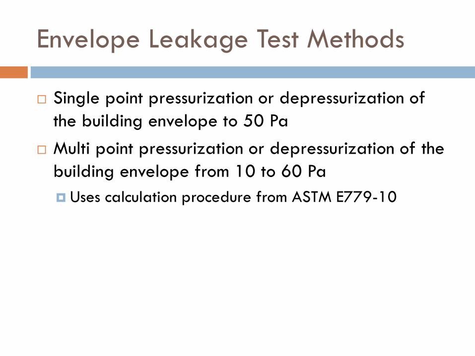
Envelope Leakage Test Methods
Single point pressurization or depressurization of the building envelope to 50 Pa
Multi point pressurization or depressurization of the building envelope from 10 to 60 Pa Uses calculation procedure from ASTM E779-10

Envelope Preparation – some details about holes…. Non-motorized dampers shall be left in their as-found positions. For
example, a fixed damper in a duct supplying outdoor air for an intermittent ventilation system that utilizes the HVAC fan shall be left in its as-found position.
Motorized dampers shall be placed in their closed positions and shall not be further sealed.
Non-dampered ventilation openings of intermittently operating local exhaust ventilation systems (e.g., bath fan, kitchen range fan) shall be left open.
Non-dampered ventilation openings of intermittently operating whole-house ventilation systems, including HVAC fan-integrated outdoor air inlets shall not be sealed.
Non-dampered ventilation openings of continuously operating whole-house ventilation systems shall be sealed

More house preparation
Normally: attic access closed, basement doors open, BUT……
If an attic is air sealed and insulated at the roof deck: Access doors shall be opened The volume of the attic spaces shall be added to the
conditioned space volume used in ratings and HERS If the basement is air sealed and insulated at the
basement ceiling: Access doors shall be closed The volume of the attic spaces shall not be included in
the conditioned space volume used in ratings and HERS

Envelope Leakage – Single Point
Pressurize or depressurize to 50 Pa Corrections for not reaching 50 Pa
Altitude and temperature corrections from ASTM
E779-10: software allowed

Multipoint Envelope Leakage
10 -60 Pa pressure range Same Altitude and temperature corrections Fit to: Q = C(dP)n using methods in ASTM E779-10:
software allowed

Envelope Leakage Test Issues: Single Point - extrapolation
` At 4 Pa for ELA +/-15%
At 1 Pa for home operation +/-25%

Envelope Leakage Test Issues: Multipoint – windy days
Strong function of windspeed: errors small < 12 mph Compromise ~ 10% Overall ~ 10% better than single point

Correcting for test uncertainty
For retrofit energy savings, conducting an energy audit, or assessing the relative enclosure air leakage of a group of buildings, then no further corrections are made
For a home energy rating or compliance with enclosure leakage limit we account for extrapolation to operating conditions: Single Point: Adjusted CFM50 = 1.1 x CFM50 Adjusted ELA = 1.1 x ELA

Conversions to other metrics
ACH50 = CFM50 x 60 / Building Volume in cubic feet Used in IECC requirements
SLA = 0.00694 x ELA in in2 / Building Floor Area in square feet Used in RESNET Standard and CA T24
NLA = SLA x (S)0.4, where S is the number of stories above grade Used in ASHRAE 62.2 for infiltration credit

Duct Leakage Test Methods
Duct Leakage pressurization or depressurization to 25 Pa Total duct leakage or Leakage to outside by pressurizing or depressurizing
the house to the same test pressure Does not separate supply from return Includes provisions for “can’t reach 25”
For Air Leakage at operating conditions: Test method A of ASTM E1554 (DeltaQ)

Total Duct Leakage – System Preparation
All zone and bypass dampers shall be set to their open position to allow uniform pressures throughout the duct system
All balancing dampers shall be left in their as-found position
Non-dampered ventilation openings are sealed if continuous and open if intermittent
You may remove registers atop carpets and seal the face of the duct boot

Total duct leakage
Exterior access panels open for unconditioned spaces containing ducts
Duct leak tester may be attached at return grille or blower access panel
Several options for duct pressure location (must be recorded)
Pressurize house to 25 Pa Zero pressure between house and ducts

Duct Leakage Applications
For compliance with a total duct leakage limit use total duct leakage
For compliance with a leakage to outside limit use either total or leakage to outside
For use in an energy audit or prediction of energy savings use leakage to outside

Duct Leakage Performance Issues
Some duct systems have no attempt at sealing (northern tier basements in particular) and have nonsensical pressurization results
On very windy days DeltaQ testing is unreliable What about repeatability?
Recent study on 30 homes by Building America All three tests repeated continuously for a day – about
ten repeats – so about 900 total tests

Test results – average and standard deviations
0
20
40
60
80
100
120
140
160
180
200
DQ dQsd Press Press, sd Pressout Pressout, sd
Duct
Lea
kage
, % A
ir Ha
ndle
r Fl
ow
PARR
CEE
Southface
All

Repeatability results
For DeltaQ and Total Pressurization: +/- 6% For Pressurization to outside: +/- 1% For low leak (<6% by DeltaQ) systems much better
repeatability: Pressurization: +/- 1% (800 cfm) Pressurization to outside: +/- 0.3% (115 cfm) DeltaQ: +/- 3% (30 cfm)

Ventilation Air Flow Test Methods in RESNET 380
Airflow at inlet Powered flow hood Air flow resistance Passive flow hood
Airflow at outlet Powered flow hood Bag inflation
In-duct airflow Flow measurement station
Inlet Terminal
Outlet Terminal
Directionof Airflow
Directionof Airflow
Ventilation Duct

Flow at Inlet or Outlet terminal
Powered flow hood Fan zeros pressure
between capture hood and room
Can be commercial devices or build your own

Powered flow hood
-
- - +
+
= =
= = =

Flow at Inlet Terminal
Air flow resistance Single branch only!!!!! Known air flow resistance:
measure pressure difference If you know opening area
(square inches) and pressure difference (Pa), you can build your own and use:
𝐴𝐴𝐴𝐴𝐴𝐴𝐴𝐴𝐴𝐴𝐴𝐴𝐴𝐴 (𝐶𝐶𝐶𝐶𝐶𝐶) = 𝑂𝑂𝑂𝑂𝑂𝑂𝑂𝑂𝐴𝐴𝑂𝑂𝑂𝑂 𝐴𝐴𝐴𝐴𝑂𝑂𝐴𝐴 𝑥𝑥 1.07 𝑥𝑥 (𝑑𝑑𝑑𝑑)0.5

Flow at Inlet Terminal
Passive flow hood Only if pressure difference
between hood and room < 5 Pa Many commercially available
devices are not precise or accurate enough at ventilation air flow rates (e.g., < 50 cfm)

Flow at Outlet Terminal – Bag Inflation
If you know volume (gallons) and time (seconds)
Airflow (CFM)=(8 × Volume)/(Elapsed Time )

Flow at Outlet Terminal – Bag Inflation
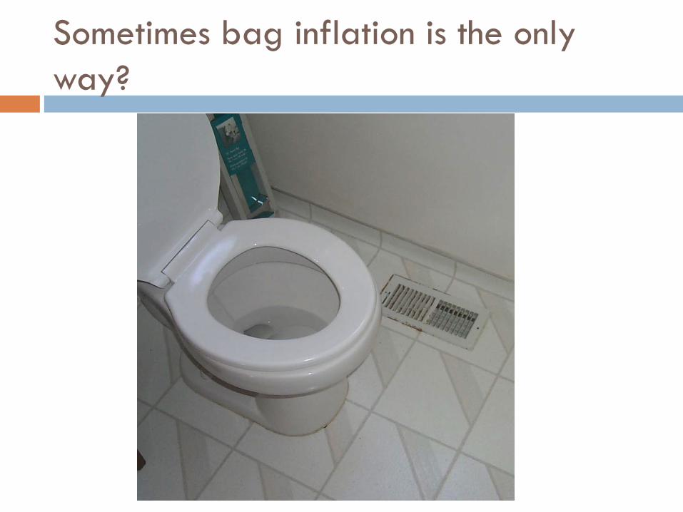
Sometimes bag inflation is the only way?

Flow at Outlet Terminal

In-Duct Air Flows
Requires air flow measurement station in duct Can be permanent or temporary installation Air flow derived from converting pressure to
average air velocity, V (fpm), and multiplying by cross-sectional area, A (ft2):
Airflow (CFM)=V x A

Current Status of RESNET 380
Soon to have 2nd public review – ONLY of things that changed from first pubic review
Please read and comment – go to RESNET website

Measuring Single Branch Air Flows
Heating, cooling, and ventilation systems 10-200 cfm Range of register sizes and configurations Inlet and outlet


- cruise at designated flows (“pressure stations” as measured by reference meter)
- correct for air density by measuring barometric pressure, temperature, relative humidity
- measure and correct for leakage after any change to the system
the testing process

- middle - edge - corner

Airflow measurement apparatus

High flow pressure drop measurement
Relative humidity Ambient temperature
High flow in-line temperature
low flow pressure drop measurement
low flow in-line temperature
static pressure
Airflow measurement apparatus

Images of terminals
4-1 4-3 4-4
6-1 6-2 6-3 6-4
BRExInlet BRExInlet
4-2


0
5
10
15
20
0%
5%
10%
15%
20%
25%
30%
35%
40%
ABT701 DIFF EBT721 EPB TECEFM TECFB testo417 mea
n ab
solu
te e
rror
in c
ubic
fee
t per
min
ute
mea
n ab
solu
te e
rror
as
a %
of
refe
renc
e flo
w
Mean absolute error of all devices, for all flows

Recent study of return grill airflow measurement
CEC – wants to know what to say in Title 24 Are some techniques/devices better than others? Multi. vs. single branch issues AKA Insertion Losses
(Heisenberg?)

Laboratory Testing
Grille A
Main trunk
Nozzle/pitot array reference flow meter
Grille B Iris damper/branch reference flow meters
Grille C
Branch Diameter (in.) Pan Depth (in.) Grille Dimensions (in. x in.)
A 16 4 24x24 B 16 4 20x20 C 14 4 14x24
Furnace NO HEAT
+/- 0.5%
+/- 2%

Obsessive Air Sealing
Less than 1% air leakage

Five Measurement Devices
testo 417 ABT 701 EBT 721
LBNL Hybrid Cardboard + Fan/Flowmeter (CFF)
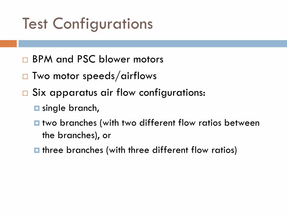
Test Configurations
BPM and PSC blower motors Two motor speeds/airflows Six apparatus air flow configurations:
single branch, two branches (with two different flow ratios between
the branches), or three branches (with three different flow ratios)

Example of individual branch measurement results: CFF
0 200 400 600 800
-10
010
2030
CFF
Branch reference flow in cfm
% d
iff. b
/t m
easu
red
bran
ches
& re
f. flo
w
BPM 1_2_3PSC 1_2_3BPM 1_1_2PSC 1_1_2BPM 1_1_1PSC 1_1_1BPM 0_1_1PSC 0_1_1BPM 0_1_2PSC 0_1_2BPM 1_0_0PSC 1_0_0

Instrument Error Summary
Individual Branch Air Flow, %
Total System Air Flow, %
Mean RMS Mean RMS
ABT701 -2.8 4.8 -3.6 4.2 EBT721 9.3 10.1 9.6 10.1 LBNL Hybrid 7.5 10.1 6.3 7.7 CFF 2.5 7.5 1.7 5.7 Testo417 16.5 19.7 17.3 18.3
Mean – for a population of systems RMS – for an individual system
If +/-10% good enough then all but vane anemometer OK

Future Directions for Air Flow Measurement
- Developing ASTM test method to
rate air flow devices - Recommend use of powered flow
hoods - Revise testing standards to reduce
uncertainty in measurements

Chris Stratton: [email protected] Iain Walker: [email protected]

in-line reference airflow meters

2 – 685 Gerand Venturi flow meter - Used to measure low flows (15 – 60 cfm)
Pressure taps

Thermo Brandt 6” NZP 1000 Series Flow Sensor - used to measure high flows (60 – 225 cfm)
Up- and downstream Pressure taps
Flow straightener
Pitot array

Low flow reference meter calibrated using tracer gas


