air-insulated medium voltage switchgear, 24 kv … · air-insulated medium voltage switchgear, 24...
TRANSCRIPT
ABB Power Distribution
ZS1
Air-insulated medium voltage switchgear, 24 kV
Instruction manual BA 398/03 E
Your safety first – always!
• Only install switchgear and/or switchboards in enclosed rooms suitable forelectrical equipment.
• Ensure that installation, operation and maintenance are carried out byspecialist electricians only.
• Comply in full with the legally recognized standards (DIN VDE / IEC), theconnection conditions of the local electrical utility and the applicable safetyat work regulations.
• Observe the relevant information in the instruction manual for all actionsinvolving switchgear and switchboards.
• Danger!
Pay special attention to the hazard notes in the instruction manual marked withthis warning symbol.
• Make sure that under operation condition of the switchgear or switchboardthe specified data are not exceeded.
• Keep the instruction manual accessible to all persons concerned withinstallation, operation and maintenance.
• The user’s personnel are to act responsibly in all matters affecting safety atwork and the correct handling of the switchgear.
If you have any further questions on this instruction manual, the members of ourfield organization will be pleased to provide the required information.
That's why our instruction manual begins with these recommendations:
WARNUNGAnerkannte Regeln der Technik und Betriebsanleitungen
beachten !
Gefährliche Spannung kann elektrischen Schock und Verbrennungen verursachen.
Vor Aufnahme von Arbeiten jeder Art dieses Gerät unbedingt freischalten,erden und kurzschließen.
WARNINGAlways observe the instruction manual and follow the rules
of good engineering practice !
Hazardous voltage can cause electrical shock and burns.
Disconnect power, then earth and short-circuit before proceedingwith any work on this equipment.

4 ABB Power Distribution
Contents Page
1 Summary 51.1 General 51.2 Standards and specifications 51.3 Operating conditions 51.3.1 Normal operating conditions 51.3.2 Special operating conditions 52 Technical data 62.1 Electrical data 62.2 Resistance to internal arc faults 62.3 Dimensions and weights 73 Panel design and equipment 83.1 Basic structure and variants 93.2 Enclosure and partitioning 93.2.1 Ventilation of the panels 93.3 Compartments in the panels 93.3.1 Busbar compartment 93.3.2 Circuit-breaker compartment 93.3.3 Withdrawable parts 93.3.4 Cable connection compartment 103.3.5 Control cabinet 103.4 Interlocks/protection against maloperation 113.4.1 Panel internal interlocking 113.4.2 Interlocks between panels 113.4.3 Locking devices 113.5 VD4 circuit-breaker run on-block 113.6 Coding of the control wiring
plug connection 114 Despatch and storage 234.1 Condition on delivery 234.2 Packaging 234.3 Transport 234.4 Delivery 234.5 Intermediate storage 235 Assembly of the switchgear at site 255.1 General site requirements 255.2 Foundations 255.2.1 Floor frame on a concrete floor 255.2.2 Raised false floor 265.3 Assembly of the switchgear panels 275.4 Installation of the busbars and bushings 285.5 Installation of the top mouted boxes 295.5.1 Voltage transformer for busbart metering 293.3.2 Earthing switch for busbar earthing 295.6 Pressure rerlief ducts 295.7 Connection of the cables 305.7.1 Power cables 305.7.2 Control cables 305.8 Earthing of the switchgear 305.9 Laying the ring circuits 305.10 Final erection work 30
Contents Page
6 Operation of the switchgear 556.1 Commissioning 556.1.1 Preparatory of work 556.1.2 Start-up 566.2 Switching operations 566.2.1 Withdrawable circuit-breaker part 576.2.2 Circuit-breaker, type VD4 586.2.3 Circuit-breaker, type VM1 596.2.4 Withdrawable metering parts 596.2.5 Earthing switch, type EK6 596.2.6 Busbar earthing switch 606.2.7 Switch disconnector 606.2.8 Insulationg guard plate 616.2.9 Electrical/medical display/monitoring 616.2.10 Earthing and short-circuiting with
earthing cable sets 616.3 Test procedures 626.3.1 Testing the off-circuit condition 626.3.2 Testing for in-phase condition 626.3.3 Current and voltage testings 627 Maintenance 717.1 General 717.2 Inspection 717.3 Servicing 727.4 Repair 727.4.1 Switchgear in general 727.4.2 Replacement of complex functional groups 737.5 Testing withdrawable parts with a VD4
type circuit-breaker 747.5.1 Motor-driven withdrawable parts 747.5.2 Checking the correctness of dimensional
settings 747.5.3 Checking auxiliary switch settings on
withdrawable parts 747.5.4 Checking the direction of the rotation of
the travel motors on motor-drivenwithdrawable parts 75
7.5.5 Testing of interlock conditions 757.6 Tests on the panel 767.6.1 Auxiliary switch settings on the
earthing switch 767.7 Spare parts, auxiliary materials, lubricants 767.7.1 Spare parts 767.7.2 Auxiliary materials, lubricants 76
We reserve all rights to this publication. Misuse, particularlyincluding duplication and making available of this manual-or extracts- to third parties is prohibited. The data andillustrations are without engagement. Subject to changewithout notice.© ABB Calor Emag Mittelspannung GmbH, 2000
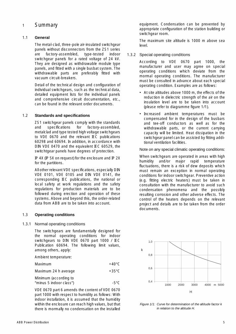
ABB Power Distribution 5
1 Summary
1.1 General
The metal-clad, three-pole air-insulated switchgearpanels without disconnectors from the ZS1 seriesare factory-assembled, type-tested indoorswitchgear panels for a rated voltage of 24 kV.They are designed as withdrawable module typepanels, and fitted with a single busbat system. Thewithdrawable parts are preferably fitted withvacuum circuit-breakers.
Detail of the technical design and configuration ofindividual switchgears, such as the technical data,detailed equipment lists for the individual panelsand comprehensive circuit documentation, etc.,can be found in the relevant order documents.
1.2 Standards and specifications
ZS1 switchgear panels comply with the standardsand specifications for factory-assembled,metalclad and type tested high voltage switchgearsto VDE 0670 and the relevant IEC publications60298 and 60694. In addition, in accordance withDIN VDE 0470 and the equivalent IEC 60529, theswitchtgear panels have degrees of protection.
IP 4X (IP 5X on request) for the enclosure and IP 2Xfor the partitions.
All other relevant VDE specifications, especially DINVDE 0101, VDE 0105 and DIN VDE 0141, thecorresponding IEC publications, the national orlocal safety at work regulations and the safetyregulations for production materials are to befollowed during erection and operation of thesesystems. Above and beyond this, the order-relateddata from ABB are to be taken into account.
1.3 Operating conditions
1.3.1 Normal operating conditions
The switchgears are fundamentally designed forthe normal operating conditions for indoorswitchgears to DIN VDE 0670 part 1000 / IECPublication 60694. The following limit values,among others, apply:
Ambient temperature:
Maximum +40°C
Maximum 24 h average +35°C
Minimum (according to“minus 5 indoor class“) -5°C
VDE 0670 part 6 amends the content of VDE 0670part 1000 with respect to humidity as follows: Withindoor installation, it is assumed that the humiditywithin the enclosure can reach high values, but thatthere is mormally no condensation on the installed
equipment. Condensation can be prevented byappropriate configuration of the station building orswitchgear room.
The maximum site altitude is 1000 m above sealevel.
1.3.2 Special operating conditions
According to VDE 0670 part 1000, themanufacturer and user may agree on specialoperating conditions which deviate from themormal operating conditions. The manufacturermust be consulted in advance about each specialoperating condition. Examples are as follows:
• At site altitudes above 1000 m, the effects of thereduction in dielectric strength of the air on theinsulation level are to be taken into account(please refer to diagramme figure 1/1).
• Increased ambient temperatures must becompensated for in the design of the busbarsand tee-off conductors as well as for thewithdrawable parts, or the current carryingcapacity will be limited. Heat dissipation in theswitchgear panel can be assisted by fitting addi-tional ventilation facilities.
Note on any special climatic operating conditions:
When switchgears are operated in areas with highhumidity and/or major rapid temperaturefluctuations, there is a risk of dew deposits whichmust remain an exception in normal operatingconditions for indoor switchgear. Preventive action(e.g. fitting electric heaters) must be taken inconsultation with the manufacturer to avoid suchcondensation phenomena and the possiblyresulting corrosion and other adverse effects. Thecontrol of the heaters depends on the relevantproject and details are to be taken from the orderdocuments.
Figure 1/1: Curve for determination of the altitude factor kin relation to the altitude H.
0,41000 2000 3000 4000 5000m
0,6
0,8
1,0
k
H
6 ABB Power Distribution
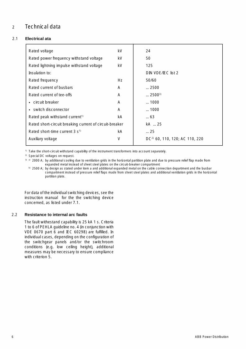
2 Technical data
2.1 Electrical ata
Rated voltage kV 24
Rated power frequency withstand voltage kV 50
Rated lightning impulse withstand voltage kV 125
Insulation to: DIN VDE/IEC list 2
Rated frequency Hz 50/60
Rated current of busbars A …2500
Rated current of tee-offs A …25003)
• circuit breaker A …1000
• switch disconnector A …1000
Rated peak withstand current1) kA …63
Rated short-circuit breaking current of circuit-breaker kA …25
Rated short-time current 3 s1) kA …25
Auxiliary voltage V DC2) 60, 110, 120; AC 110, 220
1) Take the short-circuit withstand capability of the instrument transformers into account separately.2) Special DC voltages on request.3) a) 2000 A; by additional cooling due to ventilation grids in the horizontal partition plate and due to pressure relief flap made from
expanded metal instead of sheet steel plates on the circuit-breaker compartmentb) 2500 A; by design as stated under item a and additional expanded metal on the cable connection department and the busbar
compartment instead of pressure relief flaps made from sheet steel plates and additional ventilation grids in the horizontalpartition plate.
For data of the individual switching devices, see theinstruction manual for the the switching deviceconcerned, as listed under 7.1.
2.2 Resistance to internal arc faults
The fault withestand capability is 25 kA 1 s. Criteria1 to 6 of PEHLA guideline no. 4 (in conjunction withVDE 0670 part 6 and IEC 60298) are fulfilled. Inindividual cases, depending on the configuration ofthe switchgear panels and/or the switchroomconditions (e.g. low ceiling height), additionalmeasures may be necessary to ensure compliancewith criterion 5.
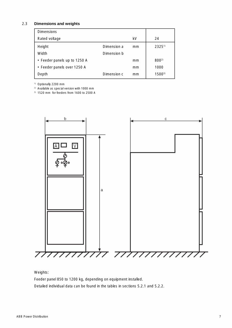
ABB Power Distribution 7
2.3 Dimensions and weights
Dimensions
Rated voltage kV 24
Height Dimension a mm 23251)
Width Dimension b
• Feeder panels up to 1250 A mm 8002)
• Feeder panels over 1250 A mm 1000
Depth Dimension c mm 15003)
1) Optionally 2200 mm2) Available as special version with 1000 mm3) 1520 mm for feeders from 1600 to 2500 A
Weights:
Feeder panel 850 to 1200 kg, depending on equipment installed.
Detailed individual data can be found in the tables in sections 5.2.1 and 5.2.2.
A V
a
b c
8 ABB Power Distribution
3 Panel design and equipment
3.1 Basic structure and variants(Figures 3/1 to 3/3)
The basis for the ZS1 panel is the incoming/outgoing feeder panel with vacuum circuit-breakerusing insertion technology. It is divided into busbarcompartment A, circuit-breaker compartment B,cable compartment C and the control cabinet D forthe secondary equipment. Apart from this, thereare variants for all operating needs. The pictures3/1 to 3/3 show possible configurations of a panelincluding electrical equipment.
For a busbar sectionalizing, two panels arenecessary, the coupling panel with thewithdrawable circuit-breaker part and a bus riserpanel (optional with busbar metering and earthing).When setting up the switchgear in two rows, thebusbar sectionalizing can be combined with a barconnection between the two sets of switchgear. Inequipment without busbar sectionalizing, a directbar connection between the busbars will beestablished.
With ZS1 panels it is possible to set up a doublebusbar installation in accordance with the twobreaker method. This duplex arrangement ispossible both with back to back or front to frontpositioning.
Apart from this, panels with fixed-mountedswitch-disconnectors of type C3 (e.g. for feed toa station service transformer) are provided.
Depending on rated short-time current and theceiling height of the circuit-breaker compartment, apressure relief duct on the panel would perhaps berequired.
Further details about the installation and equippingof the switchgear can be obtained from the orderdocuments.
3.2 Enclosure and partitioning(Figure 3/3, 5/11, 5/27)
Enclosure and internal partitioning of the panels areof high quality aluminium-zinc coated steel sheets,2 mm thick. The three high voltage compartments(busbar compartment circuit-breaker compartmentand cabel connection compartment) are equippedwith top-mounted, secured pressure relief flaps.These open in the case of overpressure due to aninternal arc fault.
The front of the panel is closed off by pressureresistant doors which open to an angle of almost180°. Cable and circuit-breaker compartments havetheir own doors. The circuit-breaker compartmentsare equipped with sight glasses made of securityglass. Neighbouring panels are partitioned from oneanother by the side walls of each panel and the air
cushion which remains between these walls as aresult of the design when the panels are joinedtogether.
The enclosure is completed by top-mountedpressure-relief flaps which are, according to therated tee-off conductor current, made of sheetsteel or expanded metal and below by means ofthe floor-covering 17 made of sheet steel whichcannot be magnetized. The pressure-relief flapsare secured with steel screws on one longitudinalside and on the other longitudinal side with plasticscrews. In the case of internal overpressure, theplastic screws are the point of rupture.
An Ith limitation can be achieved under arc faultconditions by undelayed breaker release effectedby auxiliary switches 11.5 (figure 5/27) whichcontrol the pressure relief devices (standardequipment for higher short-circuit capacity).
The necessary safety measures to counteract theeffects of an internal arc fault must be ensured inconnection with the ceiling height. This may inindividual cases possibly necessitate additionaloperator protection measures on the switchgearpanels. Such measures include:
1. Mounting of a pressure relief duct 50 on the top ofthe switchgear, with further channels leading outof the switchroom in an appropriate form for thebuilding design. The shock wave and arcdischarge are channelled off in ducts (figure 5/11)
2. Mounting of a pressure relief duct with blow-outapertures located above the duct at the ends ofthe switchgear and pointing towards the centreof the switchgear. The shock wave and arcdischarge then emerge in an extremelyattenuated form and at a location which is notcritical for the operating personnel.
Part of the internal partitioning are the busbars-rearwall of the busbar compartment 84, theintermediate wall 9, the mounting plate 12 with theshutters 12.1/12.2 and the horizontal partition 20.The internal partitioning makes it possible to havesafe access to the circuit-breaker and cablecompartments even when the busbars are live.
The low voltage compartment for the secondaryequipment is completely protected from the highvoltage area due to its steel-sheet casing.
On the end sides, cover plates ensure a goodappearance and are mechanically and thermicallyarc fault proof in case of such an event in the endpanel.
Doors and rear walls as well as the cover plates arethoroughly cleaned and treated against corrosionbefore receiving a high-quality double coating ofpaint. The finishing coat is in the standard colourRAL 7035 (special colours by agreement). Thestoving procedure completes the work and impartsa notable insensitivity to impacts and corrosion.
ABB Power Distribution 9
3.2.1 Ventilation of the panels(Figures 3/1 to 3/3, 5/27, 6/21, 6/22)
For the purpose of ventilation in cases of certainrated currents in the busbar and tee-off bars,openings in the outer enclosure are necessary.
For incoming air to the circuit-breaker com-partment, the horizontal partition is provided withair-vents 20.2. The degree of protection IP4X andsafety in case of releases of hot gas caused by anarc fault are provided by the flap 20.3 in the raisedfalse floor. In the case of outgoing air, the presssurerelief flaps are provided made of expanded metalinstead of clad metal sheets. The form and size ofthe vents in the expanded metal provide the degreeof protection IP4X.
In case of an increased ambient temperature (>40 °C)and/or increased frequency (60 Hz) may it bynecessary to install a fan into the horizontal partitionat an increased current (2500 A). This is nostandard. Please refer to figure 6/21 and 6/22.
The controlling of this fan depends on the conditionof the contract and is available in the contractdocuments.
3.3 Compartments in the panels
3.3.1 Busbar compartment
(Figures 3/3, 5/9, 5/15 to 5/21)
The busbars 3 have a D-shaped cross-sectionmade of copper or aluminium and are laid insections from panel to panel. According to thecurrent rating, single or double configuration isused. They are held by the flat tee-off conductor 2and if installed the busbar bushings 29. No specialconnecting clamps are needed.
Busbars and tee-off conductors are insulated bymeans of shrink-on sleeves. The bolt connectionsin the busbar system are covered by insulatingcovers 58, so that the entire configuration iscompletely free of arc fault points of origin.
In conjunction with bushing plates 28 (or 28.2) and29, panel by panel partitioning is possible.
3.3.2 Circuit-breaker compartment
(Figures 3/3, 3/6 to 3/10, 3/14, 3/17, 6/7, 6/9, 6/10,6/23)
The circuit-breaker compartment contains all thenecessary equipment for the mutual functioning ofthe withdrawable part and the panel. It is, as thebusbar compartment, metally partitioned on allsides.
The isolating tulips 5 together with the fixed isolatedcontacts are in the mounting plate 12. Alsoincluded are the metal shutters 12.1/12.2 whichcover the insertion openings. The shutters are
opened by means of the actuating bars 13.16 ofthe withdrawable breaker part using lever 38 wheninserting into the service position and are closedwhen it is removed. In the test/disconnectedposition of the withdrawable part, a partitioning byseparation is established in the main circuit current.The connection of the control wiring which must beestablished for test purposes need not beinterrupted when in the test/disconnected position.
In the test/disconnected position, the withdrawablepart is still completely inside the panel with the doorclosed. The ON/OFF push button located on thebreaker, and the mechanical indicators for ON/OFFand CHARGED/DISCHARGED can be observedthrough a sight glass.
The switching operations are carried out with thedoors closed. Installation of an additionalmechanical switching device for manual operationof the circuit-breaker in the service position is alsopossible.
The socket 10.1 for the control wiring is fixed-mounted in the circuit-breaker compartment.
3.3.3 Withdrawable parts
(Figures 3/3, 3/6 to 3/8, 3/10 to 3/13, 3/15 to 3/21)
1. Withdrawable circuit-breaker parts
The withdrawable circuit-breaker forms a com-plete module consisting of the circuit-breakertype VD4, type VM1 or SF6 circuit-breaker type HA,the withdrawable assembly 13.15, the isolatedcontact arm 4.2 with the contact system 4.3 andthe control wiring plug 10.2.
The withdrawable assembly 13.15 and the circuit-breaker are coupled via a multipole control-wiringplug connection 10.3.
The withdrawable assembly establishes themechanical connection between the panel and thecircuit-breaker. The fixed part is connected to thepanel by forking, form-coded on both sides. Themovable part with the circuit-breaker is movedmanually or by a motor by way of a spindle,between the service or test/disconnected positionswith the front doors closed. Service and test/disconnected positions are exactly registered bymeans of auxiliary switches, which register the finalposition reached and the angular position of thespindle.
The earthing connection between the with-drawable part and the panel is established by itsrollers and the travel rails 42 which are bolted intothe panel. The surfaces of all the parts of theearthing circuit are zink-galvanized.
Withdrawable parts of the same design aremutually interchangeable. In the case of the with-drawable parts having the same dimensions, butdifferent equipping of the circuit-breaker, the
10 ABB Power Distribution
codification of the control wiring plug prevents non-permitted connections between the withdrawablepart and the panel.The coding is indicated in theorder documents.
2. Other withdrawable parts
In place of the circuit-breaker type VD4, thewithdrawable part can also be fitted to act as a“disconnecting device“ with a fixed current-bridge in VD4 pole-casing or with a SF6 circuit-breaker (fabricated by ABB Sace).
The withdrawable part is used in the meteringpanel with voltage transformers 95.1 with orwithout HRC fuses as required. The HRC fusesare located in the insulated contact arms whichare fixed to the P.T.s.
3.3.4 Cable connection compartment
(Figures 3/3, 5/12 to 5/14, 5/28 to 5/30)
The cable compartment contains current trans-former 7, voltage transformer 8 and earthing switch6 in each case according to the individual operatingrequirements.
The cable compartment is constructed for theinstallation of three current transformers. Should allthree current transformers not be required, dum-mies will be installed instead with the sameinstallation and connection procedures.
The fixed-mounted voltage transformers areconnected on the primary side with flexible,completely insulated wirings which are inserted intothe transformers.
In certain circumstances it is possible to useremovable voltage transformers. They can beequipped with HRC fuses similar to the design inthe metering panel.
The earthing switch type EK6 can be used eitherwith manual or motor-operated mechanism. Itsswitching position will be indicated by means of theauxiliary switch both mechanically and electrically.
In the 800 mm wide panel, it is possible (accordingto choice) to prepare for up to three parallel three-core cables if required. In the standard version, theintended equipping is a plastic cable with singlecable core protection.
In the 1000 mm wide panel up to six parallel plasticcables can be connected also with single cablecore protection and push-on sealing ends.
An alternative could be the 800 mm wide panelsocket-contacts with inner cones for connection tothe cable plugs. Customer wishes regarding theconnections to bars or special cable or sealing-endtypes must be clarified during the order-planningphase.
In place of three cable cores, three surge arrestorscan be fixed-mounted. An alternative would be,under certain conditions, to have these in awithdrawable form.
In the Duplex version, the cable compartmentis modified as follows:
• In the back to back version, the connectionbetween the two panels consists of flat copperbars.
• In the front to front version it consists of made-up plastic insulated cables or insulated busbarcapacitance grading device, depending on thecurrent.
3.3.5 Control cabinet
(Figures 3/3, 3/5, 5/26 and 5/27)
The control cabinet is for all matters of control andprotection suitable for both conventional or moderncontrol technology.
Apart from the usual case, a control cabinet of 580mm or 705 mm in height, there is also a 1100 mmhigh version for especially comprehensivesecondary technology, which has a panel height of2720 mm.
If the secondary devices are not intended for doorinstallation, they are mounted on perforated metalsheet 37.3. This is stored folded-up to enable anysubsequent changes to the wiring. In place of theperforated metal steet are installed profile rails forfixing control equipment. In the lower part of thecontrol cabinet, three rows of terminal strips are onthe swivelling terminal strips holder 37.4 and belowthese, auxiliary switch 10.4 for the control wiringplug is easily accessible.
For doors in which devices with higher voltage thanthat of low-voltage protection are installed, asecure and complete protection conductorconnection must be established. The corrosionprotected hinge of the control cabinet correspondsto these requirements (DIN VDE 0660 part 500).Protection against contact to clamps and devicescorresponds to VGB 4.
Secondary wiring internal to the panel is in a ducton the right side of the panel. The left side of thepanel is for the external wiring. The ducts arecovered with steel sheet metal 43. At the side of thecontrol cabinet are holes for sliding in the ringconductors.
Detailed information about the secondarytechnology and to the relevant material used ineach case can be obtained from the secondarycheck-list pertaining to the order.
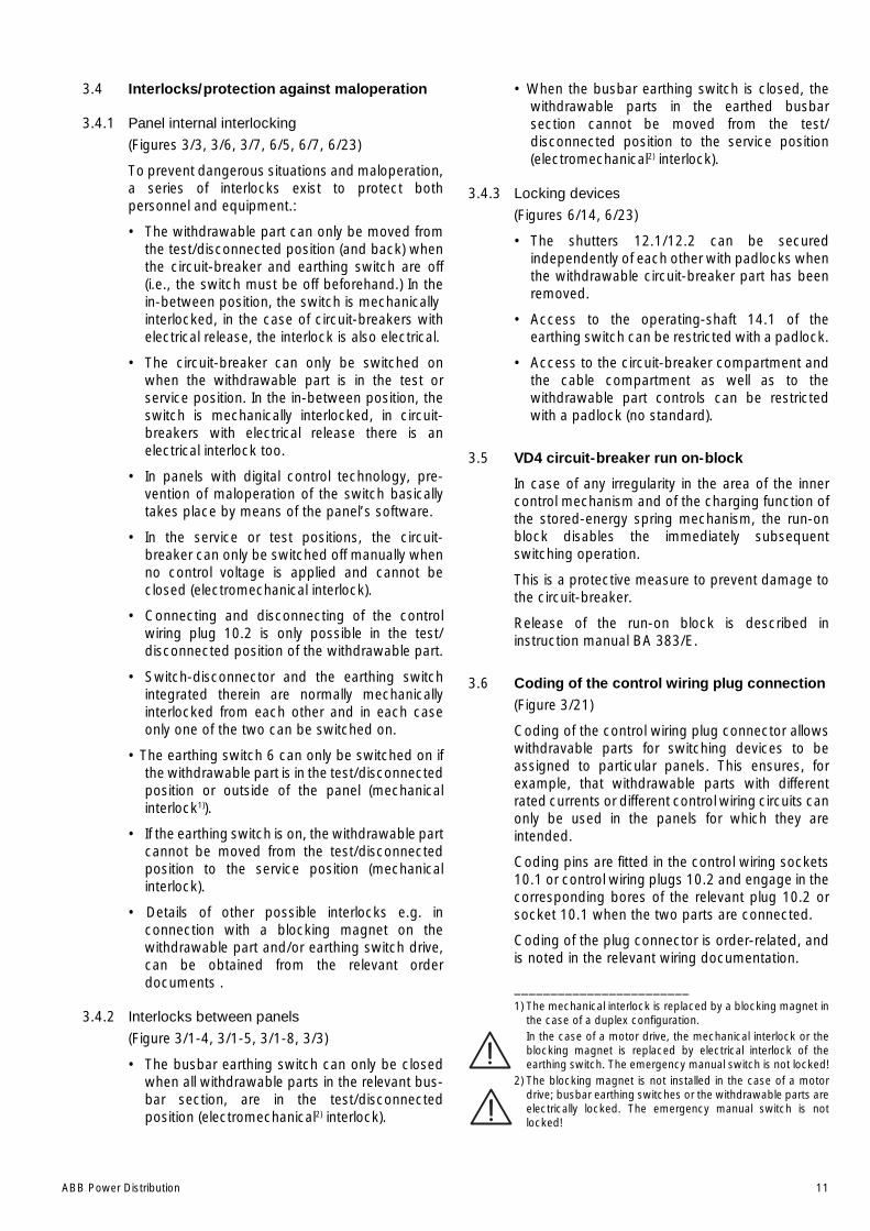
ABB Power Distribution 11
3.4 Interlocks/protection against maloperation
3.4.1 Panel internal interlocking
(Figures 3/3, 3/6, 3/7, 6/5, 6/7, 6/23)
To prevent dangerous situations and maloperation,a series of interlocks exist to protect bothpersonnel and equipment.:
• The withdrawable part can only be moved fromthe test/disconnected position (and back) whenthe circuit-breaker and earthing switch are off(i.e., the switch must be off beforehand.) In thein-between position, the switch is mechanicallyinterlocked, in the case of circuit-breakers withelectrical release, the interlock is also electrical.
• The circuit-breaker can only be switched onwhen the withdrawable part is in the test orservice position. In the in-between position, theswitch is mechanically interlocked, in circuit-breakers with electrical release there is anelectrical interlock too.
• In panels with digital control technology, pre-vention of maloperation of the switch basicallytakes place by means of the panel’s software.
• In the service or test positions, the circuit-breaker can only be switched off manually whenno control voltage is applied and cannot beclosed (electromechanical interlock).
• Connecting and disconnecting of the controlwiring plug 10.2 is only possible in the test/disconnected position of the withdrawable part.
• Switch-disconnector and the earthing switchintegrated therein are normally mechanicallyinterlocked from each other and in each caseonly one of the two can be switched on.
• The earthing switch 6 can only be switched on ifthe withdrawable part is in the test/disconnectedposition or outside of the panel (mechanicalinterlock1)).
• If the earthing switch is on, the withdrawable partcannot be moved from the test/disconnectedposition to the service position (mechanicalinterlock).
• Details of other possible interlocks e.g. inconnection with a blocking magnet on thewithdrawable part and/or earthing switch drive,can be obtained from the relevant orderdocuments .
3.4.2 Interlocks between panels
(Figure 3/1-4, 3/1-5, 3/1-8, 3/3)
• The busbar earthing switch can only be closedwhen all withdrawable parts in the relevant bus-bar section, are in the test/disconnectedposition (electromechanical2) interlock).
• When the busbar earthing switch is closed, thewithdrawable parts in the earthed busbarsection cannot be moved from the test/disconnected position to the service position(electromechanical2) interlock).
3.4.3 Locking devices
(Figures 6/14, 6/23)
• The shutters 12.1/12.2 can be securedindependently of each other with padlocks whenthe withdrawable circuit-breaker part has beenremoved.
• Access to the operating-shaft 14.1 of theearthing switch can be restricted with a padlock.
• Access to the circuit-breaker compartment andthe cable compartment as well as to thewithdrawable part controls can be restrictedwith a padlock (no standard).
3.5 VD4 circuit-breaker run on-block
In case of any irregularity in the area of the innercontrol mechanism and of the charging function ofthe stored-energy spring mechanism, the run-onblock disables the immediately subsequentswitching operation.
This is a protective measure to prevent damage tothe circuit-breaker.
Release of the run-on block is described ininstruction manual BA 383/E.
3.6 Coding of the control wiring plug connection(Figure 3/21)
Coding of the control wiring plug connector allowswithdravable parts for switching devices to beassigned to particular panels. This ensures, forexample, that withdrawable parts with differentrated currents or different control wiring circuits canonly be used in the panels for which they areintended.
Coding pins are fitted in the control wiring sockets10.1 or control wiring plugs 10.2 and engage in thecorresponding bores of the relevant plug 10.2 orsocket 10.1 when the two parts are connected.
Coding of the plug connector is order-related, andis noted in the relevant wiring documentation.
________________________1) The mechanical interlock is replaced by a blocking magnet in
the case of a duplex configuration.In the case of a motor drive, the mechanical interlock or theblocking magnet is replaced by electrical interlock of theearthing switch. The emergency manual switch is not locked!
2) The blocking magnet is not installed in the case of a motordrive; busbar earthing switches or the withdrawable parts areelectrically locked. The emergency manual switch is notlocked!

12 ABB Power Distribution
Figure 3/1-1: Outgoing feeder, 24 kV, …1250 A, 25 kA with fixedinstalled voltage transformers alternatively with lowvoltage compartment 1100 mm height
Figure 3/1-2: Outgoing feeder, 24 kV, …1250 A, 25 kA voltagetransformers withdrawable
180
1500
2200 23
25
2720
685
495
180
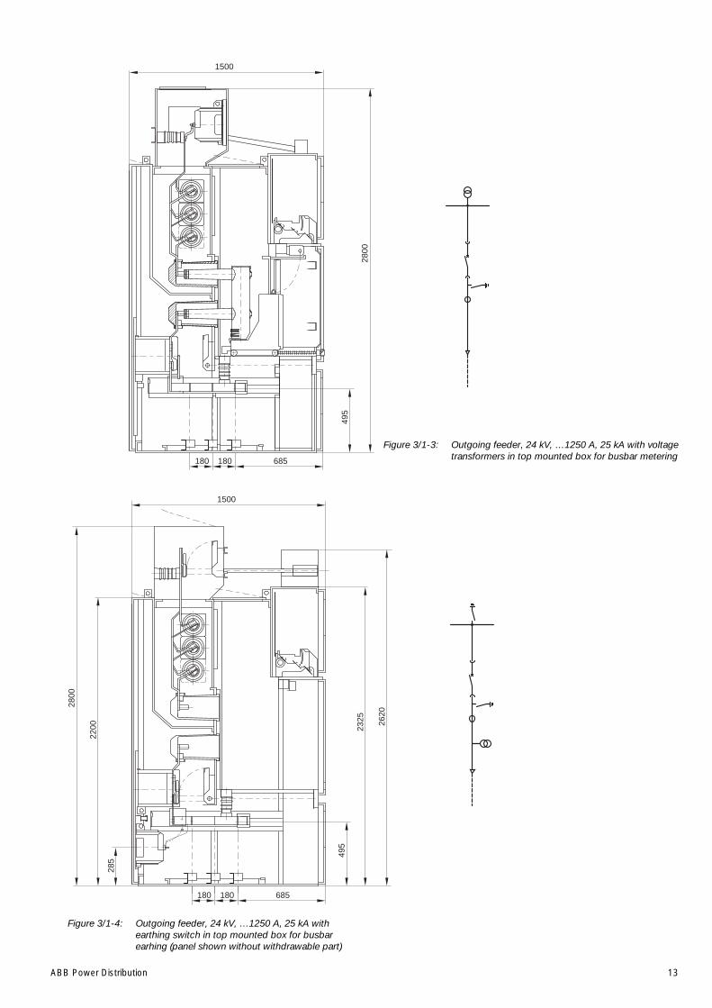
ABB Power Distribution 13
Figure 3/1-3: Outgoing feeder, 24 kV, …1250 A, 25 kA with voltagetransformers in top mounted box for busbar metering
Figure 3/1-4: Outgoing feeder, 24 kV, …1250 A, 25 kA withearthing switch in top mounted box for busbarearhing (panel shown without withdrawable part)
180180
1500
495
2800
685
285
2200
2800
2620
2325
180180
1500
495
685
14 ABB Power Distribution
Figure 3/1-5: Busbar sectionalizing, 24 kV, 1250 A, 25 kA withearthing switch Type EK6x) earthing switch optional
Figure 3/1-6: Busbar rizer, 24 kV, 1250 A, 25 kA withwithdrawable metering unit
x)x)
ABB Power Distribution 15
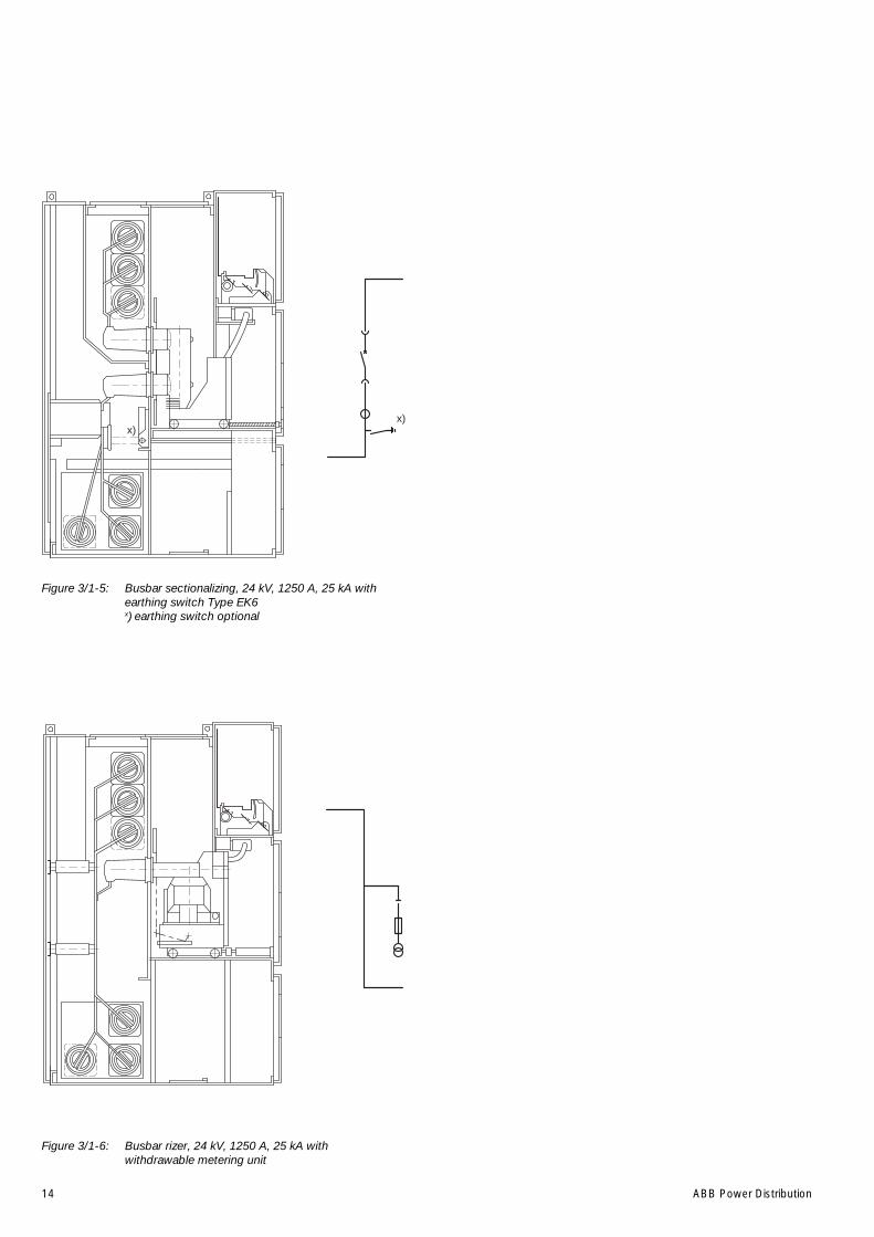
Figure 3/1-7: Outgoing feeder, 24 kV, 2000 A, 25 kA withnatural cooling
Figure 3/1-8: Busbar metering 24 kV voltage transformerswithdrawable, with busbat earthing switch
180 820180
1520
2200 23
25
2720
1500
2200 23
25
2720

16 ABB Power Distribution
Figure 3/1-9: Outgoing feeder 24 kV 630 A with switch-disconnectorwith fuses and integrated earthing switch
Figure 3/2: ZS1 Duplex - switchgear 24 kV, 1000 A, 25 kA, doublebusbar switchgear according to the two-breakermethod, panel installation back to back.
392
180
1500
2200 23
25
685180
2325
(22
00)
3005
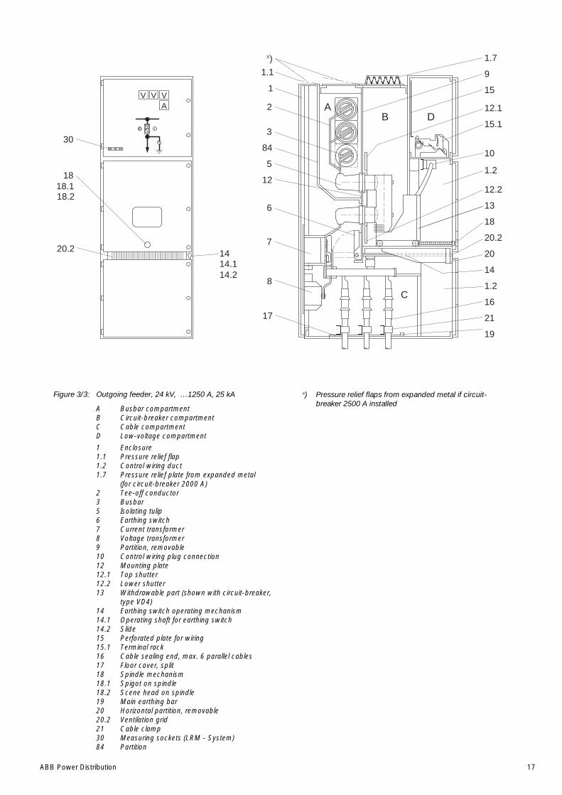
ABB Power Distribution 17
Figure 3/3: Outgoing feeder, 24 kV, …1250 A, 25 kA
A Busbar compartmentB Circuit-breaker compartmentC Cable compartmentD Low-voltage compartment
1 Enclosure1.1 Pressure relief flap1.2 Control wiring duct1.7 Pressure relief plate from expanded metal
(for circuit-breaker 2000 A)2 Tee-off conductor3 Busbar5 Isolating tulip6 Earthing switch7 Current transformer8 Voltage transformer9 Partition, removable10 Control wiring plug connection12 Mounting plate12.1 Top shutter12.2 Lower shutter13 Withdrawable part (shown with circuit-breaker,
type VD4)14 Earthing switch operating mechanism14.1 Operating shaft for earthing switch14.2 Slide15 Perforated plate for wiring15.1 Terminal rack16 Cable sealing end, max. 6 parallel cables17 Floor cover, split18 Spindle mechanism18.1 Spigot on spindle18.2 Scene head on spindle19 Main earthing bar20 Horizontal partition, removable20.2 Ventilation grid21 Cable clamp30 Measuring sockets (LRM - System)84 Partition
13
12.1
9
17
8
7
6
3
2
1
1.1
10
1.2
DBA
C
VAVV
1.7
15
15.1
20.2
20
14
1.2
16
21
19
84
5
12
1414.114.2
30
18.118
18.2
20.2
18
12.2
X)
x) Pressure relief flaps from expanded metal if circuit-breaker 2500 A installed
18 ABB Power Distribution
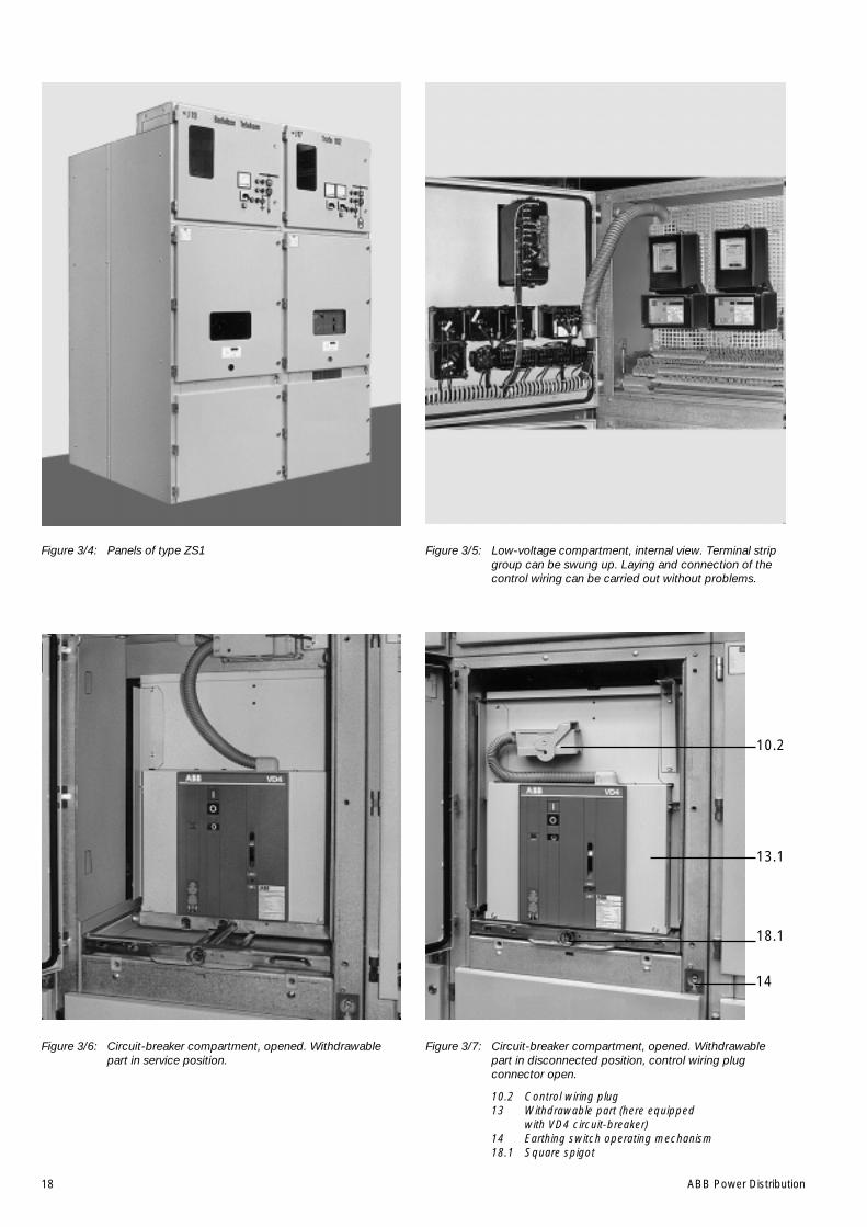
Figure 3/4: Panels of type ZS1 Figure 3/5: Low-voltage compartment, internal view. Terminal stripgroup can be swung up. Laying and connection of thecontrol wiring can be carried out without problems.
Figure 3/6: Circuit-breaker compartment, opened. Withdrawablepart in service position.
Figure 3/7: Circuit-breaker compartment, opened. Withdrawablepart in disconnected position, control wiring plugconnector open.
10.2 Control wiring plug13 Withdrawable part (here equipped
with VD4 circuit-breaker)14 Earthing switch operating mechanism18.1 Square spigot
10.2
13.1
18.1
14
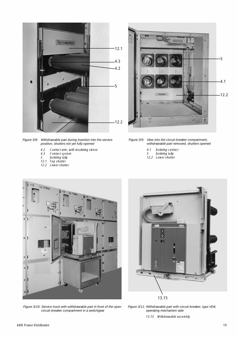
ABB Power Distribution 19
Figure 3/8: Withdrawable part during insertion into the serviceposition, shutters not yet fully opened
4.2 Contact arm, with insulating sleeve4.3 Contact system5 Isolating tulip12.1 Top shutter12.2 Lower shutter
Figure 3/9: View into the circuit-breaker compartment,withdrawable part removed, shutters opened
4.1 Isolating contact5 Isolating tulip12.2 Lower shutter
Figure 3/10: Service truck with withdrawable part in front of the opencircuit-breaker compartment in a switchgear
Figure 3/11: Withdrawable part with circuit-breaker, type VD4,operating mechanism side
13.15 Withdrawable assembly
12.1
4.3
4.2
5
12.2
12.2
5
4.1
13.15
20 ABB Power Distribution
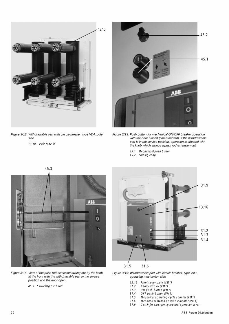
Figure 3/12: Withdrawable part with circuit-breaker, type VD4, poleside
13.10 Pole tube lid
Figure 3/15: Withdrawable part with circuit-breaker, type VM1,operating mechanism side
13.16 Front cover plate (VM1)31.2 Ready display (VM1)31.3 ON push-button (VM1)31.4 OFF push-button (VM1)31.5 Mecanical operating cycle counter (VM1)31.6 Mechanical switch position indicator (VM1)31.9 Catch for emergency manual operation lever
Figure 3/14: View of the push rod extension swung out by the knobat the front with the withdrawable part in the serviceposition and the door open
45.3 Swivelling push rod
Figure 3/13: Push button for mechanical ON/OFF breaker operationwith the door closed (non-standard). If the withdrawablepart is in the service position, operation is effected withthe knob which swings a push rod extension out.
45.1 Mechanical push button45.2 Turning knop
13.1045.2
45.1
45.3
31.9
13.16
31.231.331.4
31.5 31.6
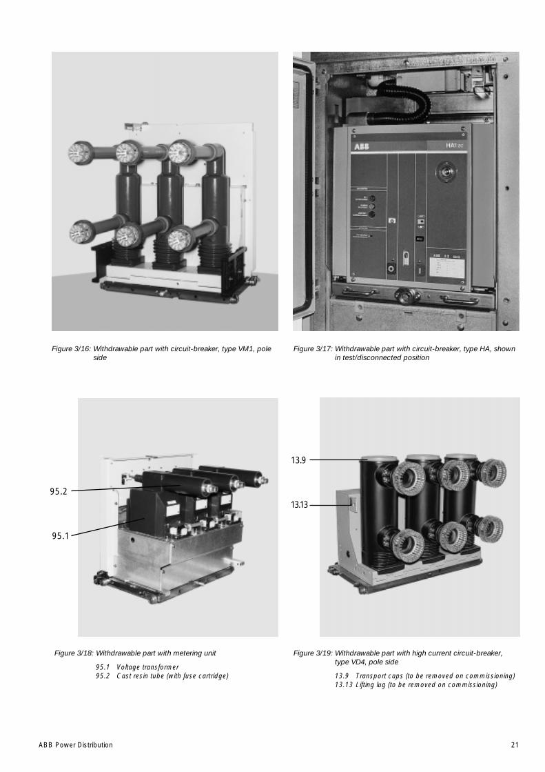
ABB Power Distribution 21
Figure 3/16: Withdrawable part with circuit-breaker, type VM1, poleside
Figure 3/17: Withdrawable part with circuit-breaker, type HA, shownin test/disconnected position
Figure 3/18: Withdrawable part with metering unit
95.1 Voltage transformer95.2 Cast resin tube (with fuse cartridge)
Figure 3/19: Withdrawable part with high current circuit-breaker,type VD4, pole side
13.9 Transport caps (to be removed on commissioning)13.13 Lifting lug (to be removed on commissioning)
13.13
13.9
95.1
95.2

22 ABB Power Distribution
Sample for coding
Control Code B1 B2 B3 B4 B5 B6
wiring Pin x x
Socket Hole
Control Hole x x
wiring Pin
Socket Code B1 B2 B3 B4 B5* B6
* B5 is used in special cases only
4745 49 46
48
4310 21
44
4211 22
32
112 23
33
213 24
34
314 25
35
415 26
36
516 27
37
617 28
38
718 29
39
819 30
40
920 31
41
50
51
52
53
54
55
56
57
58
B3(B4)
B6(B6)
B4(B3)
B1(B2)
B5(B5)
B2(B1)
10.410.5
10.4
Coding:
(...) In brackets is statedthe corresponding codingdesignation for thecontrol wiring plug (10.2)
The coding pins canbe fitted in thecontrol wiring socket (10.1)and/or in thecontrol wiring plug. (10.2)
Basic design:
Number of sockets optional,but always with the basic assignment:1, 8, 10, 20, 21, 31, 33, 40.
Sockets and pins can bemixed in the control wiringsocket (10.1) and controlwiring plug (10.2) as required
10.1
Figure 3/21: Coding of the control wiring plug connector, shown for a58 pole connection
10.1 Control wiring socket10.4 Centres for coding pins and bores10.5 Bore for the actuating pin on the control wiring plug
for controling the auxiliary switch 36, figure 7/4.
S 9 S 8 10.318.2 18.1
Figure 3/20: Withdrawable assembly for circuit-breaker, with auxiliaryswitch
S8 Test position indicatorS9 Service position indicator10.3 Control wiring plug connector for
withdrawable assembly18.1 Square spigot18.2 Scene head on spindle
ABB Power Distribution 23
4 Despatch and storage
4.1 Condition on delivery
At the time of despatch, the ZSI panels are factory-assembled, the withdrawable parts inserted intothe service position and the doors closed.
The factory-assembled panels are checked at theworks for completeness in terms of the order andsimultaneously subjected to routine testing(normally without AC voltage testing of the busbars)to VDE 0670 part 6 or IEC publication 60298, andthus tested for correct structure and function.
The busbars are not assembled. The busbarmaterial, fasteners and accessories are packedseparately.
4.2 Packaging
According to the kind of transport and country ofdestination, the panels remain unpackaged or arewelded in foil and packed in seaworthy crates. Toprotect against moisture, a drying agent isprovided:
• Panels with basic packaging or withoutpackaging.
• Panels with seaworthy packaging or similar(including packaging for containerizedshipments):
– Sealed in polythene sheeting,
– Transport drying agent bags included,
– Moisture indicator included,
– When aluminium composite sheeting is used,a sight window is fitted for checking.
• Observe the directions for use of the dryingagent bags to DIN55 473. the following applies:
– Coloured indicator blue: contents dry,
– Coloured indicator pink: contents moist (rela-tive humidity above 40%).
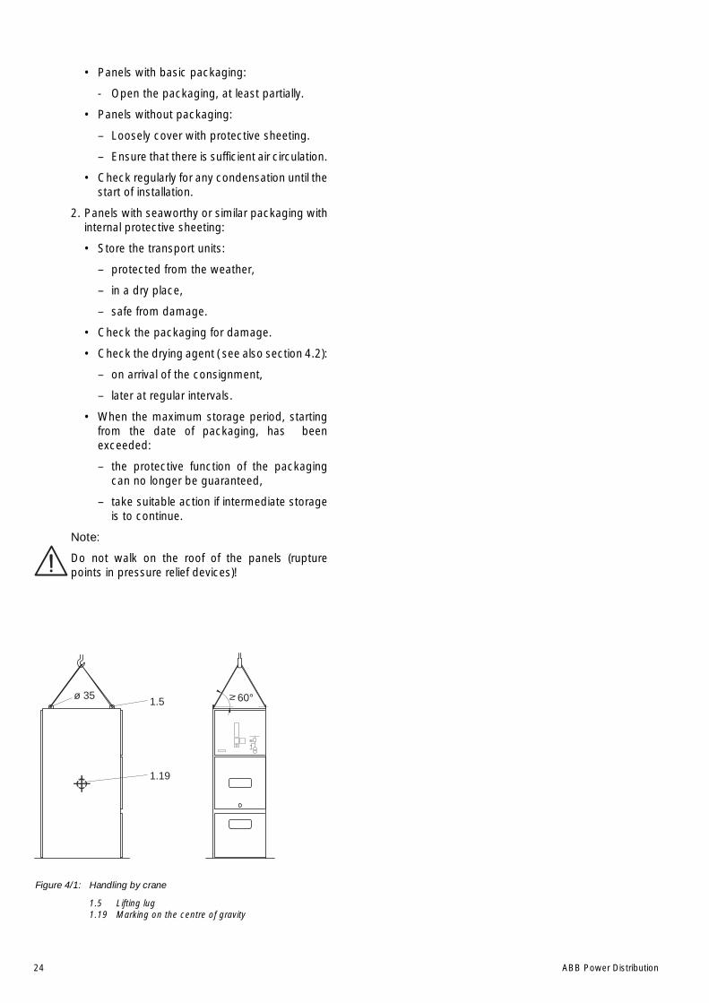
4.3 Transport(Figure 4/1)
The transport units normally comprise individualpanels, and in exceptional cases small groups ofpanels or panel assembled back to back. Thepanels are each fitted with four lifting lugs.
Transport panels upright. Take account of the highcentre of gravity. Only ever carry out loadingoperations when it has been ensured that allprecautionary measures to protect personnel andmaterials have been taken and using a
• crane,
• fork-lift truck and/or
• manual trolley jack.
Loading by crane:
• Fit lifting ropes of appropriate load capacity withshackles (opening width above 30 mm,fastening bore diameter 30 mm)
• Maintain an angle of at least 60° from the hori-zontal for the ropes leading to the crane hook.
4.4 Delivery
The responsibilities of the consignee when theswitchgear arrives at site include, but are notlimited to, the following:
• Checking the consignment for completenessand freedom from damage (e.g. also formoisture and its detrimental effects). In cases ofdoubt, the packaging must be opened and thenproperly resealed, fitting new drying agentbages, when intermediate storage is necessary.
• If any short quantities, defects or transportdamages are noted:
– To be documented on the respectiveshipping document.
– Notify the relevant carrier or forwarding agentimmediately in accordance with the relevantliability regulations.
Note:
Always take photographs to document any majordamage.
4.5 Intermediate storage
Optimum intermediate storage as far as this isnecessary at all- without detrimental conse-quences depends on compliance with a number ofminimum conditions for the panels and assemblymaterials
1. Panels with basic packaging or withoutpackaging:
• A dry well-ventilated store room with a climatein accordance with VDE 0670 part 1000/IEC60694.
• The room temperature must not fall below–5°C.
• There must not be any other unfavourable en-vironmental influences.
• Store the panels upright.
• Do not stack panels.
24 ABB Power Distribution
• Panels with basic packaging:
- Open the packaging, at least partially.
• Panels without packaging:
– Loosely cover with protective sheeting.
– Ensure that there is sufficient air circulation.
• Check regularly for any condensation until thestart of installation.
2. Panels with seaworthy or similar packaging withinternal protective sheeting:
• Store the transport units:
– protected from the weather,
– in a dry place,
– safe from damage.
• Check the packaging for damage.
• Check the drying agent ( see also section 4.2):
– on arrival of the consignment,
– later at regular intervals.
• When the maximum storage period, startingfrom the date of packaging, has beenexceeded:
– the protective function of the packagingcan no longer be guaranteed,
– take suitable action if intermediate storageis to continue.
Note:
Do not walk on the roof of the panels (rupturepoints in pressure relief devices)!
Figure 4/1: Handling by crane
1.5 Lifting lug1.19 Marking on the centre of gravity
ø 351.5
1.19
60°
ABB Power Distribution 25
5 Assembly of the switchgear at site
In the interests of an optimum installation sequenceand the insurance of a high quality standard, siteinstallation of the switchgear should only be carriedout by specially trained skilled personnel, or at leastsupervised and monitored by responsible persons.
5.1 General site requirements
On commencement of installation at site, theswitchroom must be completely finished, providedwith lighting and the electricity supply, lockable, dryand with facilities for ventilation. All the necessarypreparations such as wall openings, ducts, etc., forlaying of the power and control cables up to theswitchgear must already be complete. Whereswitchgear panels have topmounted structures forearthing switches or instrument transformers, itmust be ensured that the ceiling height is sufficientfor the opening travel of the pressure relief plates.
The ceiling height is also to be checked when thereis a top-mounted pressure relief duct.
Compliance with the conditions for indoorswitchgear to VDE 0670 part 1000, including theconditions for the “minus 5 indoor” temperatureclass must be ensured.
5.2 Foundations(Figures 5/1 to 5/8)
The switchgear is preferably to be erected on afloor frame set into the switchroom floor or on araised false floor.
The guideline structural data listed below facilitate arough calculation of the space required andpreliminary planning of the room design for aswitchgear project. When the final constructiondocuments are compiled, the binding datasupplied by ABB must always be taken intoaccount!
The stipulations of DIN 43 661 are also to becomplied with when the foundation is laid. Thisparticulary applies to evenness and straightnesstolerances as a protection for perfect installation ofthe switchgear.
Note:
The construction data for the ceiling openings forincoming conductors do not apply to trunking barswithout earthed coatings. Wider ceiling openingsare required in such cases.
5.2.1 Floor frame on a concrete floor
The Floor frame, consisting of one or more partsdepending on the size of the switchgear, can be
supplied with the switchgear by ABB Calor Emag; itis usually laid by site personnel and should ifpossible be aligned and inspected under thesupervision of a ABB specialist.
Installation of the floor frame:
• If the floor frame consists of several parts 60.1/60.2, bolt these together at the prepared jointlocations using links 60.3 in the specifiedsequence and so as to achieve a level surface.
• Place the floor frame precisely in the specifiedposition on the concrete floor in accordance withthe installation drawing.
• Enter jacking screws 60.8 and place steel strips60.4 below them.
• Carefully align the floor frame horizontally alongthe entire surface and to the correct height byscrewing the jacking screws down by aappropriate amount and using a levellinginstrument. The top edge of the floor frameshould be 2 mm above the finished floor surface.This facilitates erection and alignement of theswitchgear panels. In some cases , this meansthat the material thickness of an additional floorcovering to be fitted later must betaken intoaccount seperately. Tolerances for laying of theframe to DIN 43 661, version A,
e.g. evenness tolerance:± 1 mm within a measuring length of 1m,e.g. straightness tolerance:maximum 1 mm per m, but not more than 2 mmover the entire length of the frame.
• Slide brackets 60.5 against the frame at twopoints – for each 3m of frame length -, securethem to the concrete floor with plugs 60.7, andweld them to the frame. The set position of theframe on the concrete floor must not be alteredduring this operation!
• Weld the floor frame parts together. Grindprojecting parts and weld seams on the top ofthe frame flat.
• Make the necessary preparations for the perfectearthing of the floor frame with 30 x 4 mmgalvanized steel strip. Two connections arenecessary for long switchgears.
• When the floor topping is applied, carefullybackfill the floor frame, leaving no gaps.
• The floor frame must not be subjected to anyinjurious impacts or pressures, particulary duringthe installation phase.
If the conditions are not fulfilled, problems duringassembly of the switchgear and possibly withmovement of the withdrawable parts and openingan closing of the doors cannot be ruled out.

26 ABB Power Distribution
Structural data
Table for figures 5/1 to 5/4
5.2.2 Raised false floor
(Figures 5/5 to 5/8)
Procure the raised false floor locally from asuiteable supplier (ABB can arrange if necessary).It must meet all the specific requirements of theswitchgear. The additional intermediate framerequired for variant 1 can be supplied and installedby ABB.
Rated voltage 24 kV
Panel type ZS1 ZS1 ZS1 ZS1
System With- With- Fixed Fixeddrawable drawable
Panel width T mm 800 1000 800 1000
Aisle width G1) mm 1200 1400 1200 1400
Assembly openings
In ceilings:
Width: mm 1000 1200 1000 1200
Heidth: mm 1800 1800 1800 1800
in doors:
Width: TB mm 1000 1200 1000 1200
Heidth: TH2) mm 2750 2750 2750 2750
Panel weight kg 1000 1200 850 1000
Ceiling load kg/m2 900 850 750 700
Dimension: a mm 600 800 600 800
1) Determinated by VDE 0101 and the data for maximum panel width.2) Applies to low voltage compartements of standard height. Add 500 mm for top mounted low voltage compartements and costomized low
voltage compartements.
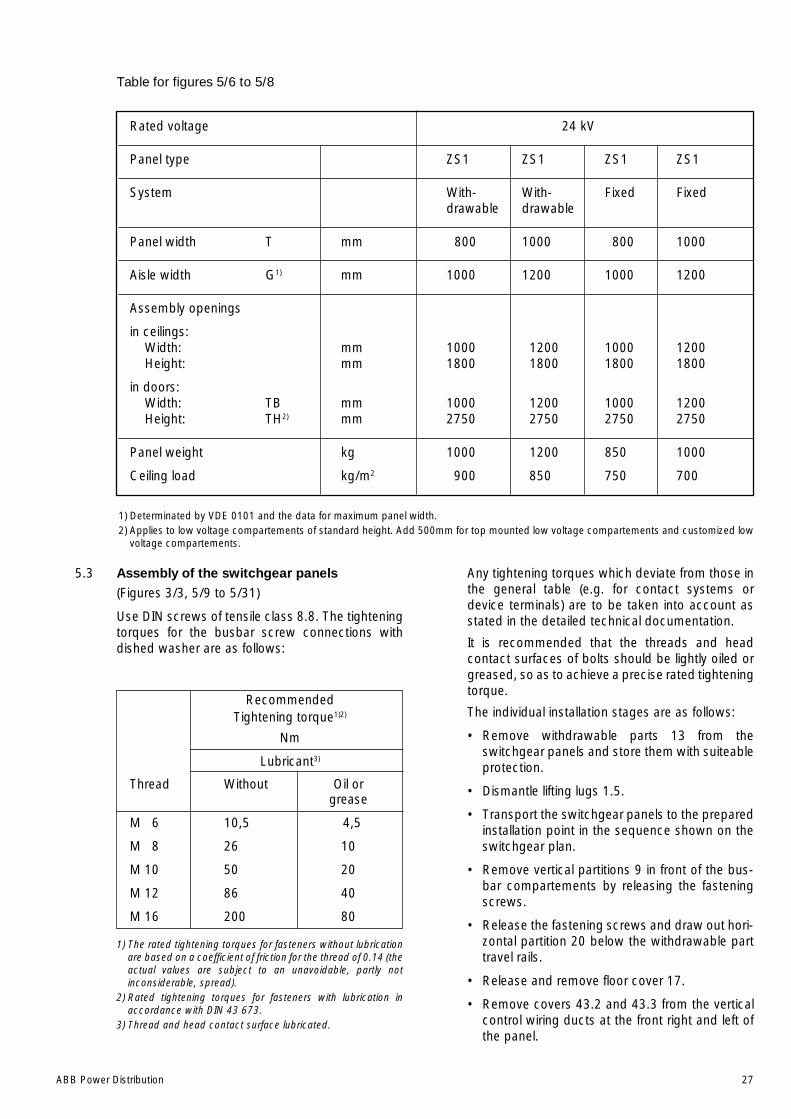
ABB Power Distribution 27
5.3 Assembly of the switchgear panels(Figures 3/3, 5/9 to 5/31)
Use DIN screws of tensile class 8.8. The tighteningtorques for the busbar screw connections withdished washer are as follows:
RecommendedTightening torque1)2)
Nm
Lubricant3)
Thread Without Oil orgrease
M 6 10,5 4,5
M 8 26 10
M 10 50 20
M 12 86 40
M 16 200 80
1) The rated tightening torques for fasteners without lubricationare based on a coefficient of friction for the thread of 0.14 (theactual values are subject to an unavoidable, partly notinconsiderable, spread).
2) Rated tightening torques for fasteners with lubrication inaccordance with DIN 43 673.
3) Thread and head contact surface lubricated.
Any tightening torques which deviate from those inthe general table (e.g. for contact systems ordevice terminals) are to be taken into account asstated in the detailed technical documentation.
It is recommended that the threads and headcontact surfaces of bolts should be lightly oiled orgreased, so as to achieve a precise rated tighteningtorque.
The individual installation stages are as follows:
• Remove withdrawable parts 13 from theswitchgear panels and store them with suiteableprotection.
• Dismantle lifting lugs 1.5.
• Transport the switchgear panels to the preparedinstallation point in the sequence shown on theswitchgear plan.
• Remove vertical partitions 9 in front of the bus-bar compartements by releasing the fasteningscrews.
• Release the fastening screws and draw out hori-zontal partition 20 below the withdrawable parttravel rails.
• Release and remove floor cover 17.
• Remove covers 43.2 and 43.3 from the verticalcontrol wiring ducts at the front right and left ofthe panel.
Rated voltage 24 kV
Panel type ZS1 ZS1 ZS1 ZS1
System With- With- Fixed Fixeddrawable drawable
Panel width T mm 800 1000 800 1000
Aisle width G1) mm 1000 1200 1000 1200
Assembly openings
in ceilings:Width: mm 1000 1200 1000 1200Height: mm 1800 1800 1800 1800
in doors:Width: TB mm 1000 1200 1000 1200Height: TH2) mm 2750 2750 2750 2750
Panel weight kg 1000 1200 850 1000
Ceiling load kg/m2 900 850 750 700
1) Determinated by VDE 0101 and the data for maximum panel width.2) Applies to low voltage compartements of standard height. Add 500mm for top mounted low voltage compartements and customized low
voltage compartements.
Table for figures 5/6 to 5/8

28 ABB Power Distribution
• If any top mounted enclosures with busbarearthing switches or instrument transformershave been removed for transport, bolt these inplace in the specified position where the rear andmiddle pressure relief plates would otherwise belocated on the switchgear panels, andreestablish the internal connections.(figures 5/11, 5/22, 5/23, 5/31).
• Fit and screw the seperate mechanismenclosures for any top mounted earthingswitches in the specified position on the lowvoltage compartement with the front edge flush.
Note the correct positions of the parts fitted on thehexagon drive shaft supplied loose, and thenremove the parts from the shaft, discarding therubber ring at the front.
Insert the drive shaft step by step at the front of themechanism enclosure until it is completely fitted,threading on the individual parts in the correctpositions for the open position of the earthingswitch.
Secure the setting rings. Adjust the mountingpositions and operating instants of the auxiliaryswitches:
1. Adjust the positions of the limit position auxiliaryswitches in their slots in such a way that there isa run-on of 0.5 mm in the fully operated positionbefore the plunger reaches the stop (for safetyreasons).
2. Limit position auxiliary switch 78.4 for earthingswitch ON must be operated immediately afterthe dead centre position of the toggle springmechanism is reached in the closing process andthe automatic quick-closing process has started.
3. Limit position auxiliary switch 78.5 for earthingswitch OFF must be operated during theopening motion of the slide 1 mm before thetongue of the slide makes contact the armatureof the unexited blocking magnet.
Fit and screw down the lids.
• Align the switchgear panels on the floor frame oneafter another for correct position and verticalalignment (deviations of the panel edges from thevertical must not exceed 2 mm, particulary at thefront) and bold the panels together. It is advisableto start from the centre when assemblingswitchgears with more than ten panels.
• When bolting together switchgear panelswithout busbar barriers, insert a shim 27between the panels above the busbar apertures.
• On switchgears with busbar barriers, also installand screw bushing plates 28/28.2 externally tothe right or left hand panel wall.
• When the switchgear has been properlyassembled, fasten the panels to the concrete
floor using plugs, or weld or adequately boltthem to the foundation frame.
5.4 Installation of the busbars and bushings(Figures 5/16 to 5/23)
• Install bushings 29 (for switchgears with busbarbarriers only).
Note:
• (Upper) busbar system:
Insert bushing 29 for the lower busbar into bus-hing plate 28 from the right in contrast to theprocedure for other two bushings.
• (Lower) tie bus system:
Insert bushing 29 for the rear, lower tie bus intobushing plate 28.2 from the right in contrast tothe procedure for the other two bushings.
• Always check that there is proper contactbetween the metal tube in the bushing and thebusbar via the contact spring 29.3. Ensure thatthe contact spring is in the correct position!
• Clean the insulation on the busbar sections witha dry, soft cloth, and check for insulationdamage. Remove greasy or adhesive dirt asdiscribed in section 7.2.
• Busbar connections:
– The silver plated surfaces of the connectionsare to be cleaned with a metal free non-woven cleaning cloth and thinly and evenlycoated with Isoflex Topas NB 52 grease.
– The non-silver plated surfaces of theconnections are either brushed under greasewith a wire brush, preserving the grease film,or cleaned with a metall-free non-wovencleaning cloth and evenly greased with a thincoat of Isoflex Topas NB 52.
• Prepare insulating covers 58 and lids 58.5 to suitthe relevant busbar connections and threadthem onto the busbar.
• Install the busbars panel by panel. Screw on theindividual busbar elements one obove the other(depending on the system layout) and in line withthe flat tee-off conductor. Use the hexagonsocket head screws 163 as provided. Fortightening torque see the table above. Use twodished washers for each screw.
• Bolt one holder 58.1 to each end of the busbarsto support the insulating cover 58.
The screws for holder 58.1 are to be tightenedwith lower torque.
• Position insulating covers 58 and lids 58.5 overthe relevant bolted joint, and slide the lid onto thecover until it clicks into place.
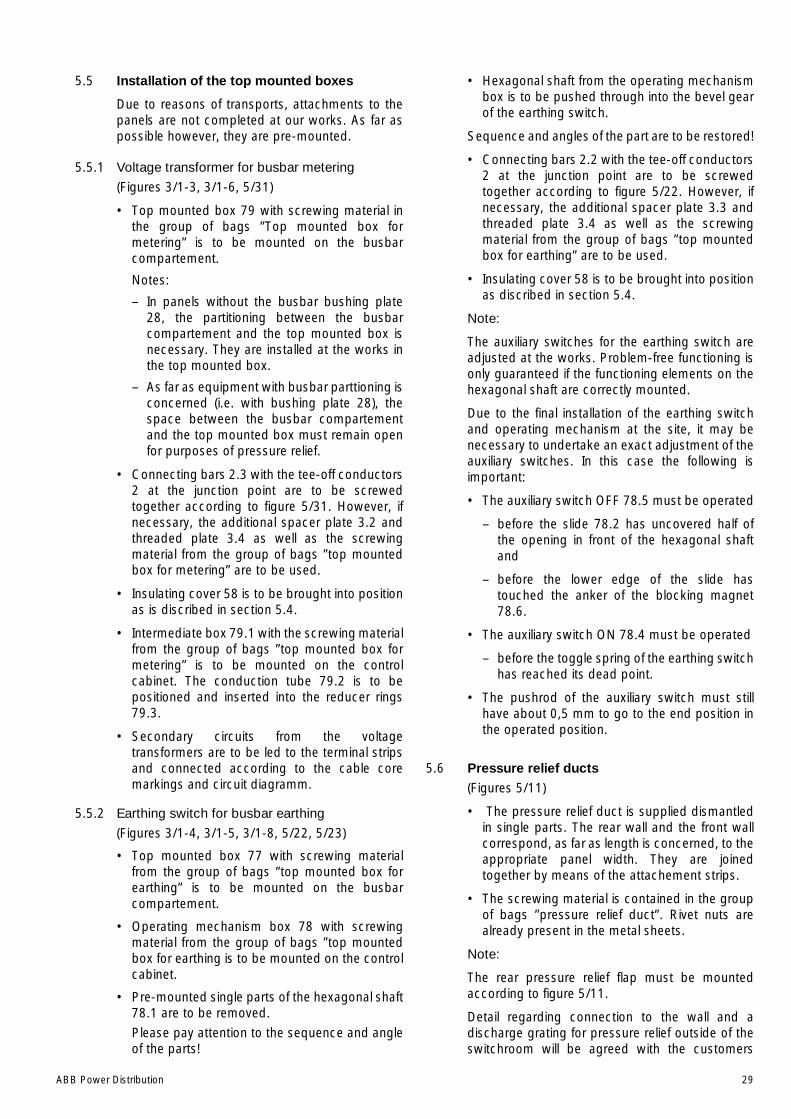
ABB Power Distribution 29
5.5 Installation of the top mounted boxes
Due to reasons of transports, attachments to thepanels are not completed at our works. As far aspossible however, they are pre-mounted.
5.5.1 Voltage transformer for busbar metering
(Figures 3/1-3, 3/1-6, 5/31)
• Top mounted box 79 with screwing material inthe group of bags ”Top mounted box formetering” is to be mounted on the busbarcompartement.
Notes:
– In panels without the busbar bushing plate28, the partitioning between the busbarcompartement and the top mounted box isnecessary. They are installed at the works inthe top mounted box.
– As far as equipment with busbar parttioning isconcerned (i.e. with bushing plate 28), thespace between the busbar compartementand the top mounted box must remain openfor purposes of pressure relief.
• Connecting bars 2.3 with the tee-off conductors2 at the junction point are to be screwedtogether according to figure 5/31. However, ifnecessary, the additional spacer plate 3.2 andthreaded plate 3.4 as well as the screwingmaterial from the group of bags ”top mountedbox for metering” are to be used.
• Insulating cover 58 is to be brought into positionas is discribed in section 5.4.
• Intermediate box 79.1 with the screwing materialfrom the group of bags ”top mounted box formetering” is to be mounted on the controlcabinet. The conduction tube 79.2 is to bepositioned and inserted into the reducer rings79.3.
• Secondary circuits from the voltagetransformers are to be led to the terminal stripsand connected according to the cable coremarkings and circuit diagramm.
5.5.2 Earthing switch for busbar earthing
(Figures 3/1-4, 3/1-5, 3/1-8, 5/22, 5/23)
• Top mounted box 77 with screwing materialfrom the group of bags ”top mounted box forearthing” is to be mounted on the busbarcompartement.
• Operating mechanism box 78 with screwingmaterial from the group of bags ”top mountedbox for earthing is to be mounted on the controlcabinet.
• Pre-mounted single parts of the hexagonal shaft78.1 are to be removed.
Please pay attention to the sequence and angleof the parts!
• Hexagonal shaft from the operating mechanismbox is to be pushed through into the bevel gearof the earthing switch.
Sequence and angles of the part are to be restored!
• Connecting bars 2.2 with the tee-off conductors2 at the junction point are to be screwedtogether according to figure 5/22. However, ifnecessary, the additional spacer plate 3.3 andthreaded plate 3.4 as well as the screwingmaterial from the group of bags ”top mountedbox for earthing” are to be used.
• Insulating cover 58 is to be brought into positionas discribed in section 5.4.
Note:
The auxiliary switches for the earthing switch areadjusted at the works. Problem-free functioning isonly guaranteed if the functioning elements on thehexagonal shaft are correctly mounted.
Due to the final installation of the earthing switchand operating mechanism at the site, it may benecessary to undertake an exact adjustment of theauxiliary switches. In this case the following isimportant:
• The auxiliary switch OFF 78.5 must be operated
– before the slide 78.2 has uncovered half ofthe opening in front of the hexagonal shaftand
– before the lower edge of the slide hastouched the anker of the blocking magnet78.6.
• The auxiliary switch ON 78.4 must be operated
– before the toggle spring of the earthing switchhas reached its dead point.
• The pushrod of the auxiliary switch must stillhave about 0,5 mm to go to the end position inthe operated position.
5.6 Pressure relief ducts(Figures 5/11)
• The pressure relief duct is supplied dismantledin single parts. The rear wall and the front wallcorrespond, as far as length is concerned, to theappropriate panel width. They are joinedtogether by means of the attachement strips.
• The screwing material is contained in the groupof bags ”pressure relief duct”. Rivet nuts arealready present in the metal sheets.
Note:
The rear pressure relief flap must be mountedaccording to figure 5/11.
Detail regarding connection to the wall and adischarge grating for pressure relief outside of theswitchroom will be agreed with the customers
30 ABB Power Distribution
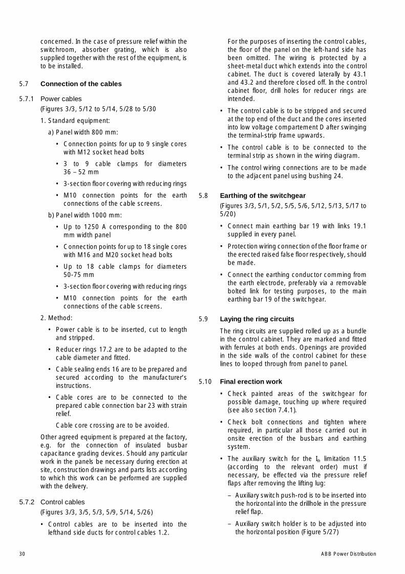
concerned. In the case of pressure relief within theswitchroom, absorber grating, which is alsosupplied together with the rest of the equipment, isto be installed.
5.7 Connection of the cables
5.7.1 Power cables
(Figures 3/3, 5/12 to 5/14, 5/28 to 5/30
1. Standard equipment:
a) Panel width 800 mm:
• Connection points for up to 9 single coreswith M12 socket head bolts
• 3 to 9 cable clamps for diameters36 – 52 mm
• 3-section floor covering with reducing rings
• M10 connection points for the earthconnections of the cable screens.
b) Panel width 1000 mm:
• Up to 1250 A corresponding to the 800mm width panel
• Connection points for up to 18 single coreswith M16 and M20 socket head bolts
• Up to 18 cable clamps for diameters50-75 mm
• 3-section floor covering with reducing rings
• M10 connection points for the earthconnections of the cable screens.
2. Method:
• Power cable is to be inserted, cut to lengthand stripped.
• Reducer rings 17.2 are to be adapted to thecable diameter and fitted.
• Cable sealing ends 16 are to be prepared andsecured according to the manufacturer‘sinstructions.
• Cable cores are to be connected to theprepared cable connection bar 23 with strainrelief.
Cable core crossing are to be avoided.
Other agreed equipment is prepared at the factory,e.g. for the connection of insulated busbarcapacitance grading devices. Should any particularwork in the panels be necessary during erection atsite, construction drawings and parts lists accordingto which this work can be performed are suppliedwith the delivery.
5.7.2 Control cables
(Figures 3/3, 3/5, 5/3, 5/9, 5/14, 5/26)
• Control cables are to be inserted into thelefthand side ducts for control cables 1.2.
For the purposes of inserting the control cables,the floor of the panel on the left-hand side hasbeen omitted. The wiring is protected by asheet-metal duct which extends into the controlcabinet. The duct is covered laterally by 43.1and 43.2 and therefore closed off. In the controlcabinet floor, drill holes for reducer rings areintended.
• The control cable is to be stripped and securedat the top end of the duct and the cores insertedinto low voltage compartement D after swingingthe terminal-strip frame upwards.
• The control cable is to be connected to theterminal strip as shown in the wiring diagram.
• The control wiring connections are to be madeto the adjacent panel using bushing 24.
5.8 Earthing of the switchgear(Figures 3/3, 5/1, 5/2, 5/5, 5/6, 5/12, 5/13, 5/17 to5/20)
• Connect main earthing bar 19 with links 19.1supplied in every panel.
• Protection wiring connection of the floor frame orthe erected raised false floor respectively, shouldbe made.
• Connect the earthing conductor comming fromthe earth electrode, preferably via a removablebolted link for testing purposes, to the mainearthing bar 19 of the switchgear.
5.9 Laying the ring circuits
The ring circuits are supplied rolled up as a bundlein the control cabinet. They are marked and fittedwith ferrules at both ends. Openings are providedin the side walls of the control cabinet for theselines to looped through from panel to panel.
5.10 Final erection work
• Check painted areas of the switchgear forpossible damage, touching up where required(see also section 7.4.1).
• Check bolt connections and tighten whererequired, in particular all those carried out inonsite erection of the busbars and earthingsystem.
• The auxiliary switch for the Ith limitation 11.5(according to the relevant order) must ifnecessary, be effected via the pressure reliefflaps after removing the lifting lug:
– Auxiliary switch push-rod is to be inserted intothe horizontal into the drillhole in the pressurerelief flap.
– Auxiliary switch holder is to be adjusted intothe horizontal position (Figure 5/27)
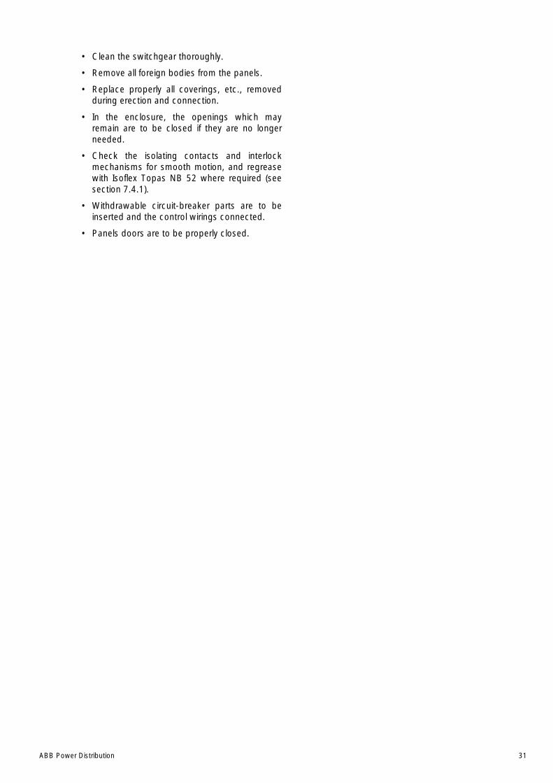
ABB Power Distribution 31
• Clean the switchgear thoroughly.
• Remove all foreign bodies from the panels.
• Replace properly all coverings, etc., removedduring erection and connection.
• In the enclosure, the openings which mayremain are to be closed if they are no longerneeded.
• Check the isolating contacts and interlockmechanisms for smooth motion, and regreasewith Isoflex Topas NB 52 where required (seesection 7.4.1).
• Withdrawable circuit-breaker parts are to beinserted and the control wirings connected.
• Panels doors are to be properly closed.
32 ABB Power Distribution
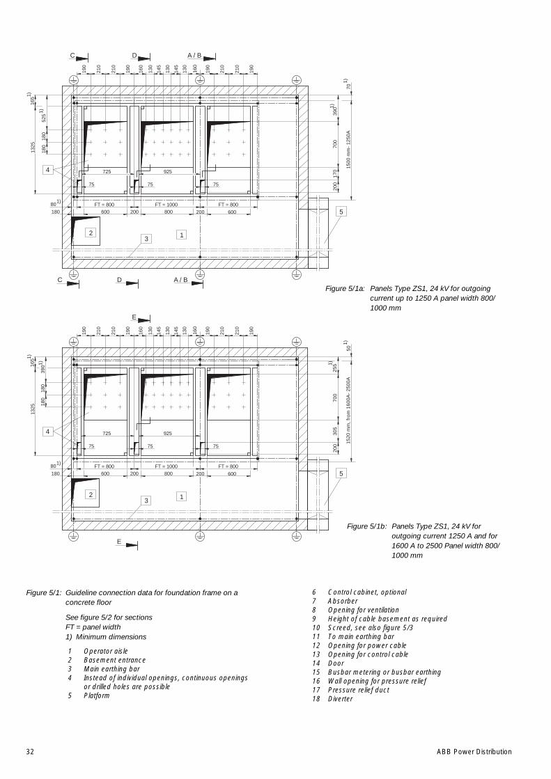
Figure 5/1: Guideline connection data for foundation frame on aconcrete floor
See figure 5/2 for sectionsFT = panel width1) Minimum dimensions
1 Operator aisle2 Basement entrance3 Main earthing bar4 Instead of individual openings, continuous openings
or drilled holes are possible5 Platform
Figure 5/1a: Panels Type ZS1, 24 kV for outgoingcurrent up to 1250 A panel width 800/1000 mm
Figure 5/1b: Panels Type ZS1, 24 kV foroutgoing current 1250 A and for1600 A to 2500 Panel width 800/1000 mm
6 Control cabinet, optional7 Absorber8 Opening for ventilation9 Height of cable basement as required10 Screed, see also figure 5/311 To main earthing bar12 Opening for power cable13 Opening for control cable14 Door15 Busbar metering or busbar earthing16 Wall opening for pressure relief17 Pressure relief duct18 Diverter
190
210
210
190
190
210
210
190
D
160
1)
1)
1500
mm
- 12
50A
70
75
80 FT = 800 FT = 1000 FT = 800600 800 600200
130
145
130
145
130
160
4
5
3 12
D
725 925
75 75
200180
700
390
170
200
525
180
180
1325
165
A / B
A / BC
C
1)
1)
1)
E
E
190
210
210
190
190
210
210
190
160
1)
1)
1520
mm
, fro
m 1
600A
- 25
00A
50
75
80 FT = 800 FT = 1000 FT = 800600 800 600200
130
145
130
145
130
160
4
5
3 12
725 925
75 75
200180
700
255
305
200
390
180
180
1325
165
1)
1)
1)
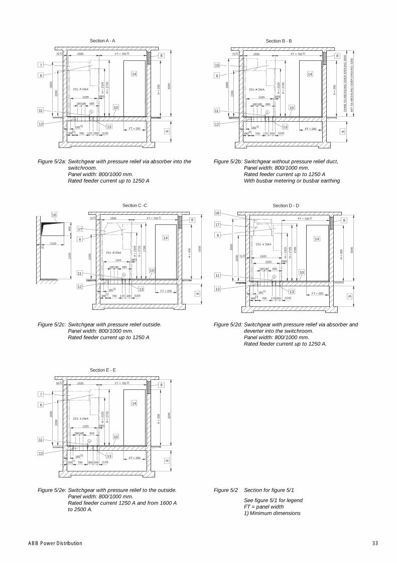
ABB Power Distribution 33
Figure 5/2a: Switchgear with pressure relief via absorber into theswitchroom.Panel width: 800/1000 mm.Rated feeder current up to 1250 A
Figure 5/2b: Switchgear without pressure relief duct,Panel width: 800/1000 mm.Rated feeder current up to 1250 AWith busbar metering or busbar earthing
Figure 5/2 Section for figure 5/1
See figure 5/1 for legendFT = panel width1) Minimum dimensions
Figure 5/2e: Switchgear with pressure relief to the outside.Panel width: 800/1000 mm.Rated feeder current 1250 A and from 1600 Ato 2500 A.
Figure 5/2d: Switchgear with pressure relief via absorber anddeverter into the switchroom.Panel width: 800/1000 mm.Rated feeder current up to 1250 A.
Figure 5/2c: Switchgear with pressure relief outside.Panel width: 800/1000 mm.Rated feeder current up to 1250 A
685
390
1)
1)
1)
180
70
FT + 200
H +
200
3200
700 200
FT + 7001500
(110)
1325 (80)
180H
= 2
325
H =
272
0
2650
9
14
10
1312
11
8
6
7
165
ZS1: 25kA
Section A - A
170
2200
1)
15
OH
NE
SS
-ME
SS
UN
G O
DE
R E
RD
UN
G 3
000
MIT
SS
-ME
SS
UN
G O
DE
R E
RD
UN
G 3
200
685
390
1)
1)
1)
180
70
FT + 200
H +
200
700 200
FT + 7001500
(110)
1325 (80)
180
H =
232
5
H =
272
0
2800
9
14
10
1312
11
8
6
165
ZS1: 25kA
Section B - B
170
2200
1)
17
16
2785
3200
685
390
1)
1)
1)
180
70
FT + 200
H +
200
700 200
FT + 7001500
(110)
1325 (80)
180
H =
232
5
H =
272
0
9
14
10
1312
11
8
6
165
ZS1: 25kA
Section C -C
170
2200
2150
650
1120
70
1)
70
2785
3200
685
390
1)
1)
1)
180
FT + 200
H +
200
700 200
FT + 700
1500
(110)
1325 (80)
180
H =
232
5
H =
272
0
9
14
10
1312
11
8
6
17
165
ZS1: 25kA
Section D - D
170
2200
18
3000
1)
820
255
1)
1)
1)
180
50
FT + 200
H +
200
3200
700 200
FT + 7001520
(110)
1325 (80)
180
H =
232
5
H =
272
0
2650
9
14
10
1312
11
8
6
7
165
ZS1: 25kA
Section E - E
305
2200
1)
34 ABB Power Distribution
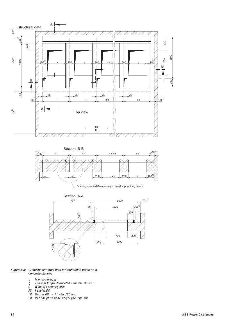
Figure 5/3: Guideline structual data for foundation frame on aconcrete stations
1) Min. dimensions*) 200 mm for pre-fabricated concrete stationsG Wide of operating aisleFT Panel widthTB Door width = FT plus 200 mmTH Door height = panel height plus 200 mm
1)
*
B
B
A
165
> 0
< 3
80
Openings slanted if necessary to avoid supportihng beams
225
200 1190
320
1500
80
7575
80
TBTH
FT FT FT 80
75 75 75 75
180 200a a a200 200 180
G
8013
251500
70
165
225
1190
700
200
320
FT FT FT
200 200 a 180
G
80 1325
700
n x a
n x FT
n x FT
n x a
A
Top view
Section B-B
Section A-A70*
60
1)
structural data
1)
1)
1)
1) 1)
1)
1)
1)
1)1)
1) 1)

ABB Power Distribution 35
Figure 5/4: Assembly of the floor frame, for figure 5/1
60.1 Floor frame part60.2 Floor frame part60.3 Link60.4 Steel strip60.5 Bracket60.6 Plug60.7 Bolt60.8 Jacking screw
A B
BA
60.5
60.7
60.6
60.1 60.3 60.2
60.4
60.8
Sections
B - BA - A
h

36 ABB Power Distribution
Figure 5/5: Guideline connection data for a raised false floor
See figure 5/6 for sectionsFT = panel width1) Minimum dimensionsx) Maximum dimensions
1 Operator aisle2 Basement entrance3 Main earthing bar4 Raised false floor structure, only shown in the
vicinity of the switchgear5 Platform6 Control panel, optional
Figure 5/5a: Panels Type ZS1, 24 kV for outgoing current up to1250 A panel width 800/1000 mm
Figure 5/5b: Panels Type ZS1, 24 kV for outgoing current 1250 Aand for 1600 A to 2500 A
7 Absorber8 Opening ventilation9 Height of cable basement as required10 Covering, site supply11 Raised false floor, site supply, top of false floor
0 to 3 mm above of finished floor12 Power cable13 To main earthing bar14 Door15 Busbar metering or busbar earthing16 Wall opening for pressure relief17 Pressure relief duct18 Diverter
ADB
ADB
C
C
190
210
210
190
190
210
210
190
1)
1)
1500
mm
- 12
50A
70
80 FT = 800 FT = 1000 FT = 800
160
130
145
130
145
130
160
4
5
3 12
525
180
180
1425
115
x) x)15 15x)15x)15
1)
1)
210
210
190
190
210
210
190
190
1)
1)
1520
mm
, ab
1600
A b
is 2
500A
50
80 FT = 800 FT = 1000 FT = 800
160
130
145
130
145
130
160
4
5
3 12
E
E
390
180
180
1425
115
x) x)15 15x)15x)15
1)
1)

ABB Power Distribution 37
Figure 5/6: Section for figure 5/5See figure 5/5 for legend
FT = panel width1) Minimum dimensions
Figure 5/6e: Switchgear with pressure relief to the outside.Panel width: 800/1000 mm.Rated feeder current 1250 A and from1600 A to 2500 A
Figure 5/6d: Switchgear with pressure relief via absorber anddeverter into the switchroomPanel width: 800/1000 mm.Rated feeder current up to 1250 A
Figure 5/6c: Switchgear with pressure relief outside.Panel width: 800/1000 mm.Rated feeder current up to 1250 A
Figure 5/6b: Switchgear without pressure relief duct,Panel width: 800/1000 mm.Rated feeder current up to 1250 AWith busbar metering or busbar earthing
Figure 5/6a: Switchgear with pressure relief via absorber into theswitchroom.Panel width: 800/1000 mm.Rated feeder current up to 1250 A
1) 1425115
685
1) 1)
180
70
FT + 200
H +
200
3200
FT + 7001500
(80)
180H
= 2
325
H =
272
0
2650
9
14
10
1312
11
8
6
7
ZS1: 25kA
Section A - A
2200
1) 1425115
685
1) 1)
180
70
FT + 200
H +
200
FT + 7001500
(80)
180
H =
232
5
H =
272
0
2800
9
14
10
1312
11
8
6
15
ZS1: 25kA
Section B - B
2200
OH
NE
SS
-ME
SS
UN
G O
DE
R E
RD
UN
G 3
000
MIT
SS
-ME
SS
UN
G O
DE
R E
RD
UN
G 3
200
1) 1425115
685
1) 1)
180
70
FT + 200
H +
200
FT + 7001500
(80)
180
H =
232
5
H =
272
0
9
14
10
1312
11
8
6
17
ZS1: 25kA
Section C - C
2200
3200
2785
2150
650
1120
70
16
1) 1425115
685
1)
1)
180
70
FT + 200
H +
200
FT + 700
1500
(80)
180
H =
232
5
H =
272
0
9
14
10
13
8
ZS1: 25kA
Section D - D
2200
3200
2785
12
11
6
17
18
3000
50
180 820
1) 1425115
1) 1)
FT + 200
H +
200
3200
FT + 7001520
(80)
H =
232
5
H =
272
0
2650
9
14
10
1312
11
8
6
7
ZS1: 25kA
Section E - E
2200
180
38 ABB Power Distribution
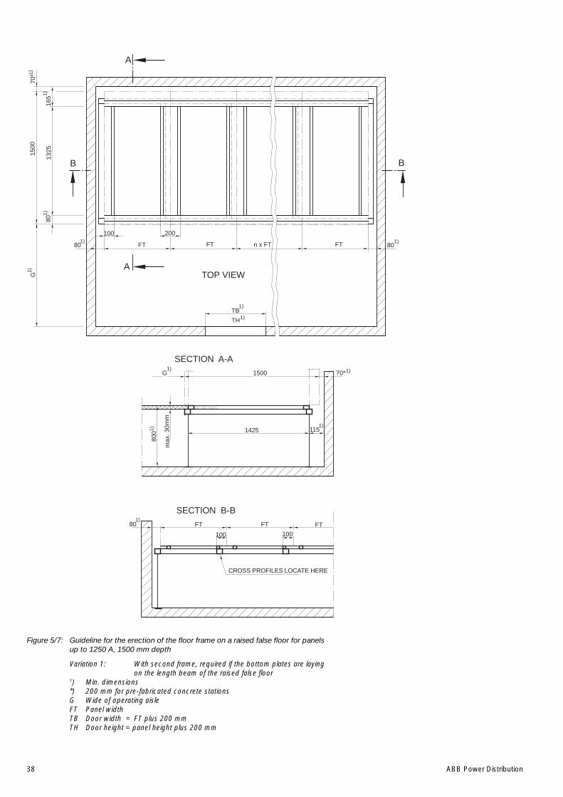
Figure 5/7: Guideline for the erection of the floor frame on a raised false floor for panelsup to 1250 A, 1500 mm depth
Variation 1: With second frame, required if the bottom plates are layingon the length beam of the raised false floor
1) Min. dimensions*) 200 mm for pre-fabricated concrete stationsG Wide of operating aisleFT Panel widthTB Door width = FT plus 200 mmTH Door height = panel height plus 200 mm
1)
1)
FT
100 100
115
max
. 30m
m
100
165
A
200
FTFT80
800 1425
70*
A
80
TB
TH
FT FT FT 80
B B
132515
00
TOP VIEW
70*
G 1500
SECTION A-A
SECTION B-B
n x FT
80
G
CROSS PROFILES LOCATE HERE
1)
1)
1)
1)
1)
1)
1)
1)
1)
1)
1)
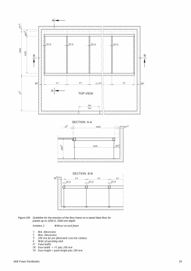
ABB Power Distribution 39
Figure 5/8: Guideline for the erection of the floor frame on a raised false floor forpanels up to 1250 A, 1500 mm depth
Variation 2: Without second frame
1) Min. dimensionsx) Max. dimensions*) 200 mm for pre-fabricated concrete stationsG Wide of operating aisleFT Panel widthTB Door width = FT plus 200 mmTH Door height = panel height plus 200 mm
165
15 x) 15 x) 15 x)15 x)
n x FT
15 x) 15 x)15 x)
FTFTFT80
800 1425
70*
A
A
80*
TB*TH*
FT FT FT 80*
B B
G
132515
00
TOP VIEW
70*
G 1500
SECTION A-A
SECTION B-B
95
1)
1)1)
1)1)
1)
1)
1)
40 ABB Power Distribution
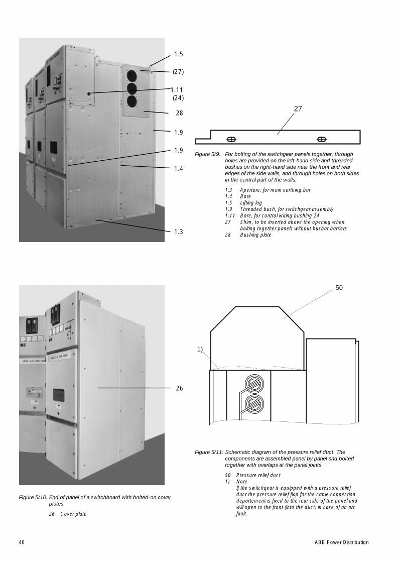
Figure 5/11: Schematic diagram of the pressure relief duct. Thecomponents are assembled panel by panel and boltedtogether with overlaps at the panel joints.
50 Pressure relief duct1) Note
If the switchgear is equipped with a pressure reliefduct the pressure relief flap for the cable connectiondepartement is fixed to the rear side of the panel andwill open to the front (into the duct) in case of an arcfault.
Figure 5/10: End of panel of a switchboard with bolted-on coverplates
26 Cover plate
Figure 5/9: For bolting of the switchgear panels together, throughholes are provided on the left-hand side and threadedbushes on the right-hand side near the front and rearedges of the side walls, and through holes on both sidesin the central part of the walls.
1.3 Aperture, for main earthing bar1.4 Bore1.5 Lifting lug1.9 Threaded bush, for switchgear assembly1.11 Bore, for control wiring bushing 2427 Shim, to be inserted above the opening when
bolting together panels without busbar barriers28 Bushing plate
27
50
1)
1.5
(27)
1.11(24)
28
1.9
1.9
1.4
1.3
26

ABB Power Distribution 41
Figure 5/15: View into the busbar compartement, shown withoutpartition and insulting covers
2 Tee-off conductor3 Busbar5 Isolating tulip9 Partition, removable49.2 Pressure relief flap, made from sheet steel
Figure 5/14: View into the high-voltage area at the front, with theremovable horizontal partition released and drawnforwards
1.8 Screw coupling20 Horizontal partition, removable43.1 Duct cover for external control cables43.2 Duct cover for external control cables
Figure 5/13: Partial view of the cable connections compartement,prepared here for connection of triple cables
1.2 Duct for external control cables17 Floor cover, split17.2 Reducer ring19 Main earthing bar19.1 Connecting link19.2 Earthing connection pin21 Cable mounting, connected to earth potential39 Mounting rail, connected to earth potential
Figure 5/12: View into cable connection compartement, max. sixparallel cables possible (see also figures 5/28 to 5/30)
6.1 Earthing switch position indicator14 Earthing switch operating mechanism17 Floor cover split17.2 Reducer ring23 Cable connection bar43.4 Duct cover for internal wiring44 Heater plate (non-standard)
14
6.1
23
44
43.4
17
17.2
1.8
43.1
20
43.2
49.2
3919.2211917.21719.11.2
3
2
9
5
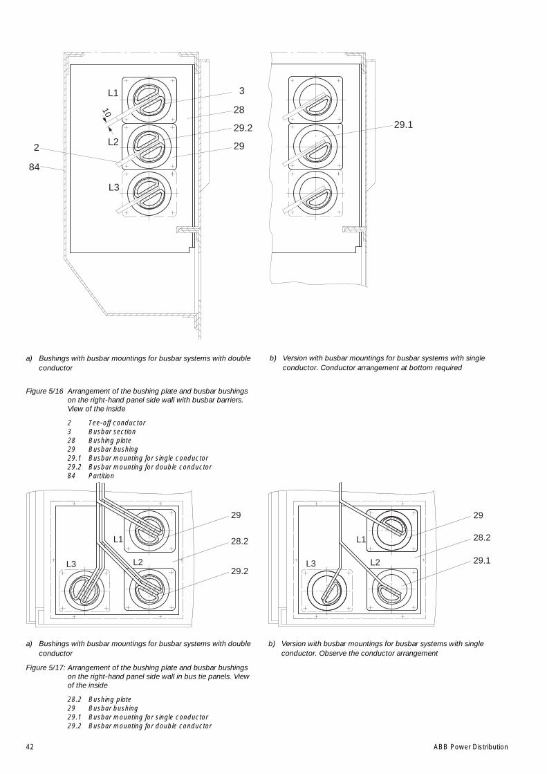
42 ABB Power Distribution
b) Version with busbar mountings for busbar systems with singleconductor. Conductor arrangement at bottom required
a) Bushings with busbar mountings for busbar systems with doubleconductor
Figure 5/16 Arrangement of the bushing plate and busbar bushingson the right-hand panel side wall with busbar barriers.View of the inside
2 Tee-off conductor3 Busbar section28 Bushing plate29 Busbar bushing29.1 Busbar mounting for single conductor29.2 Busbar mounting for double conductor84 Partition
a) Bushings with busbar mountings for busbar systems with doubleconductor
Figure 5/17: Arrangement of the bushing plate and busbar bushingson the right-hand panel side wall in bus tie panels. Viewof the inside
28.2 Bushing plate29 Busbar bushing29.1 Busbar mounting for single conductor29.2 Busbar mounting for double conductor
b) Version with busbar mountings for busbar systems with singleconductor. Observe the conductor arrangement
L3
L2
L1
10
2
84
3
28
29.2
29
29.1
L1
L2L3
29
28.2
29.2L2
L1
29
28.2
29.1L3
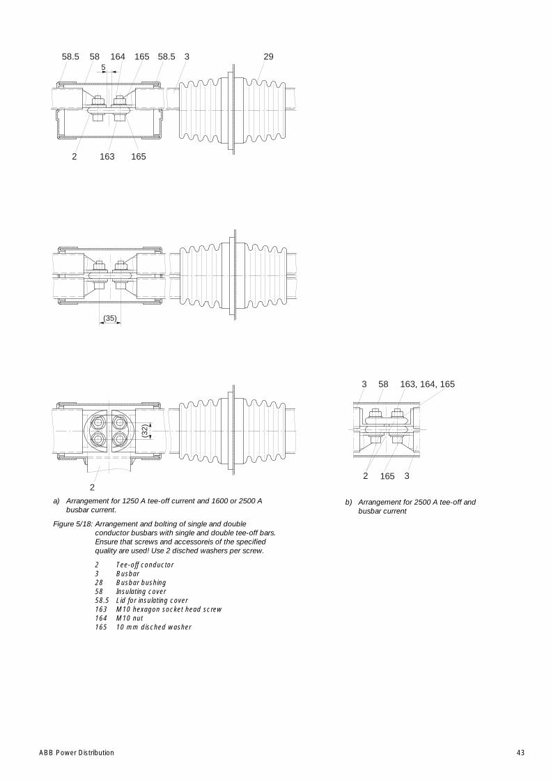
ABB Power Distribution 43
a) Arrangement for 1250 A tee-off current and 1600 or 2500 Abusbar current.
Figure 5/18: Arrangement and bolting of single and doubleconductor busbars with single and double tee-off bars.Ensure that screws and accessoreis of the specifiedquality are used! Use 2 disched washers per screw.
2 Tee-off conductor3 Busbar28 Busbar bushing58 Insulating cover58.5 Lid for insulating cover163 M10 hexagon socket head screw164 M10 nut165 10 mm disched washer
b) Arrangement for 2500 A tee-off andbusbar current
558.5 58.5 358
2 163
29164 165
165
(35)
(32)
2
163, 164, 165583
2 3165
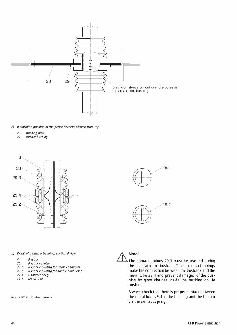
44 ABB Power Distribution
Note:
The contact springs 29.3 must be inserted duringthe installation of busbars. These contact springsmake the connection between the busbar 3 and themetal tube 29.4 and prevent damages of the bus-hing by glow charges inside the bushing on lifebusbars.
Always check that there is proper contact betweenthe metal tube 29.4 in the bushing and the busbarvia the contact spring.
a) Installation position of the phase barriers, viewed from top
28 Bushing plate29 Busbar bushing
b) Detail of a busbar bushing, sectional view
4 Busbar30 Busbar bushing29.1 Busbar mounting for single conductor29.2 Busbar mounting for double conductor29.3 Contact spring29.4 Metal tube
2928Shrink-on sleeve cut out over the bores inthe area of the bushing
29.2
29.4
29.3
3
29
29.2
29.1
Figure 5/19: Busbar barriers
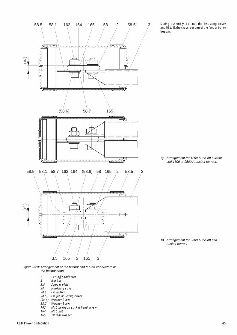
ABB Power Distribution 45
During assembly, cut out the insulating coverand lid to fit the cross-section of the feeder bar orbusbar.
a) Arrangement for 1250 A tee-off currentand 1600 or 2500 A busbar current.
b) Arrangement for 2500 A tee-off andbusbar current
Figure 5/20: Arrangement of the busbar and tee-off conductors atthe busbar ends
2 Tee-off conductor3 Busbar3.5 Spacer plate58 Insulating cover58.1 Lid holder58.5 Lid for insulating cover(58.6) Washer 2 mm58.7 Washer 3 mm163 M10 hexagon socket head screw164 M10 nut165 10 mm washer
(10
)16358.5 58.1 58 2 58.5 3164 165
(58.6) 58.7 165
(10
)
163, 16458.5 58.1 58 2 58.5 3
3.5 2 3
(58.6) 165
165 165
58.7
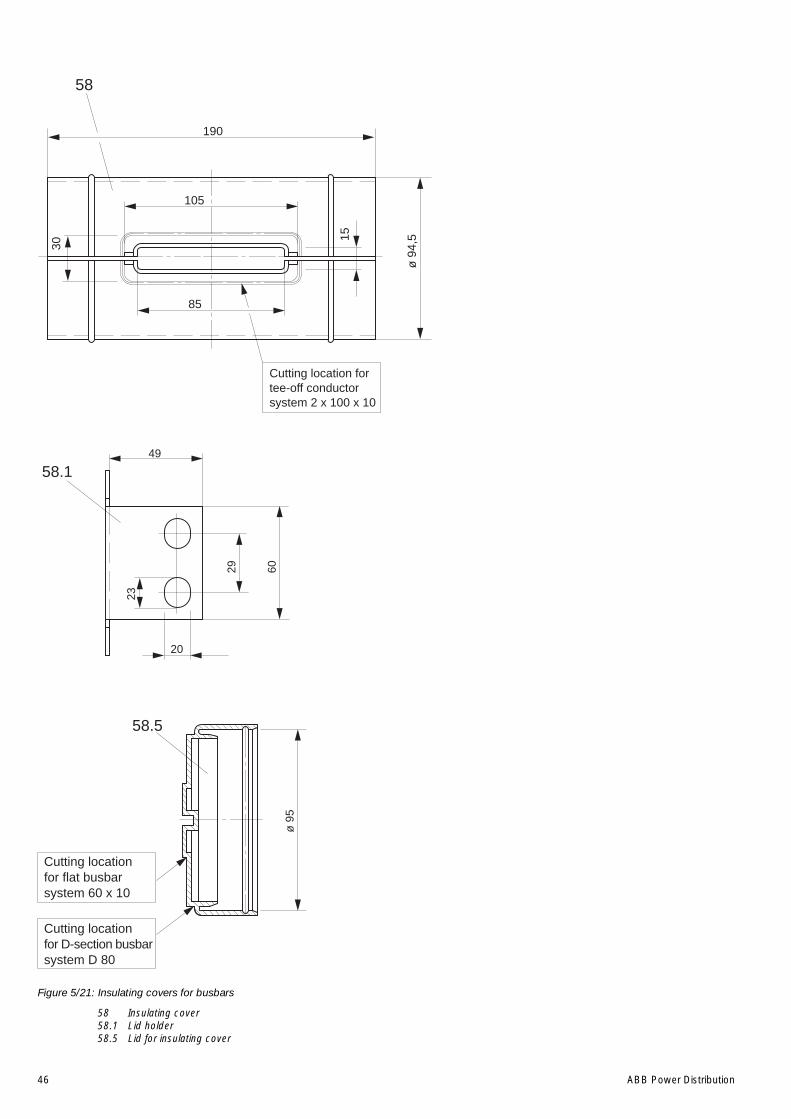
46 ABB Power Distribution
Figure 5/21: Insulating covers for busbars
58 Insulating cover58.1 Lid holder58.5 Lid for insulating cover
58
85
190
105
30
15
ø 9
4,5
Cutting location fortee-off conductorsystem 2 x 100 x 10
49
20
23
6029
58.1
58.5
ø 9
5
Cutting locationfor flat busbarsystem 60 x 10
Cutting locationfor D-section busbarsystem D 80
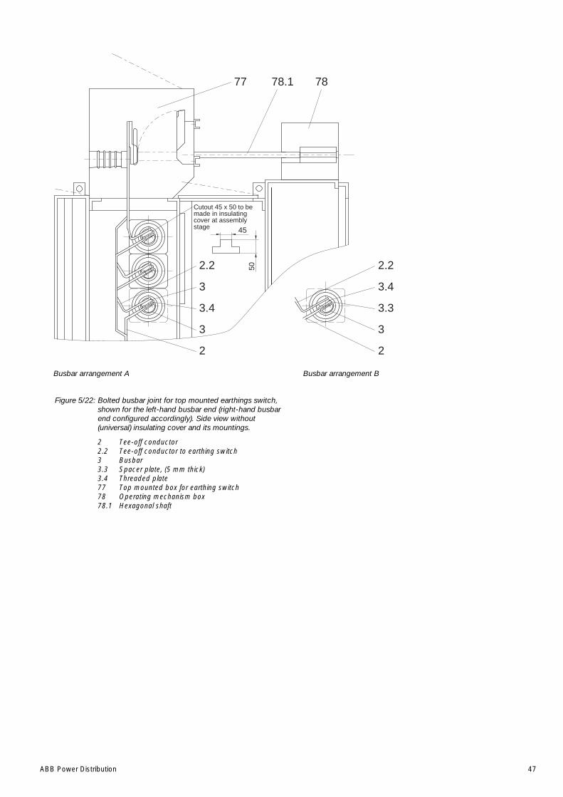
ABB Power Distribution 47
Busbar arrangement BBusbar arrangement A
Figure 5/22: Bolted busbar joint for top mounted earthings switch,shown for the left-hand busbar end (right-hand busbarend configured accordingly). Side view without(universal) insulating cover and its mountings.
2 Tee-off conductor2.2 Tee-off conductor to earthing switch3 Busbar3.3 Spacer plate, (5 mm thick)3.4 Threaded plate77 Top mounted box for earthing switch78 Operating mechanism box78.1 Hexagonal shaft
2.2
3
3.4
3
2
77
Cutout 45 x 50 to bemade in insulatingcover at assemblystage 45
50 2.2
3.4
3.3
3
2
78.1 78
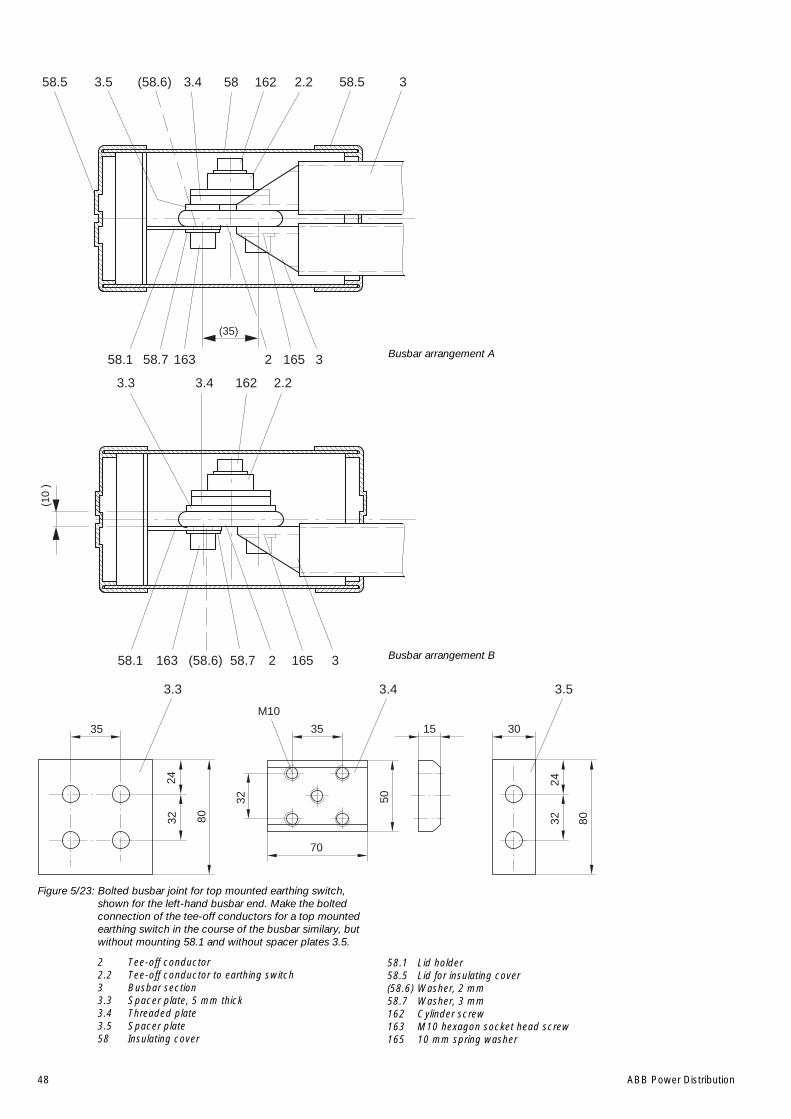
48 ABB Power Distribution
Figure 5/23: Bolted busbar joint for top mounted earthing switch,shown for the left-hand busbar end. Make the boltedconnection of the tee-off conductors for a top mountedearthing switch in the course of the busbar similary, butwithout mounting 58.1 and without spacer plates 3.5.
2 Tee-off conductor2.2 Tee-off conductor to earthing switch3 Busbar section3.3 Spacer plate, 5 mm thick3.4 Threaded plate3.5 Spacer plate58 Insulating cover
58.1 Lid holder58.5 Lid for insulating cover(58.6) Washer, 2 mm58.7 Washer, 3 mm162 Cylinder screw163 M10 hexagon socket head screw165 10 mm spring washer
(35)
58.5 32.258.5 3.43.5
58.1 3163
58(58.6)
58.7 2 165
162
301535
70
5032
2432 80
35
2432 80
3.3 3.4 3.5
M10
2.23.4
2 358.1
3.3
(10
)
163 (58.6) 16558.7
162
Busbar arrangement A
Busbar arrangement B

ABB Power Distribution 49
Figure 5/25: Operating mechanism area of a top mounted earthingswitch in detail. Precisely follow the sequence andarrangement of the parts on the drive shaft whenassembling. The figure shows the arrangement for theopen position of the earthing switch.
78.4 Limit position auxiliary switch for earthing switch ON78.5 Limit position auxiliary switch for earthing switch OFF
Figure 5/24: The earthing switch drive shaft is supplied loose whenthe top mounted enclosures are removed for transportpurposes. View for the open position of the earthingswitch with individual mechanism parts fitted in thepositions for correct function.
78.5
78.4
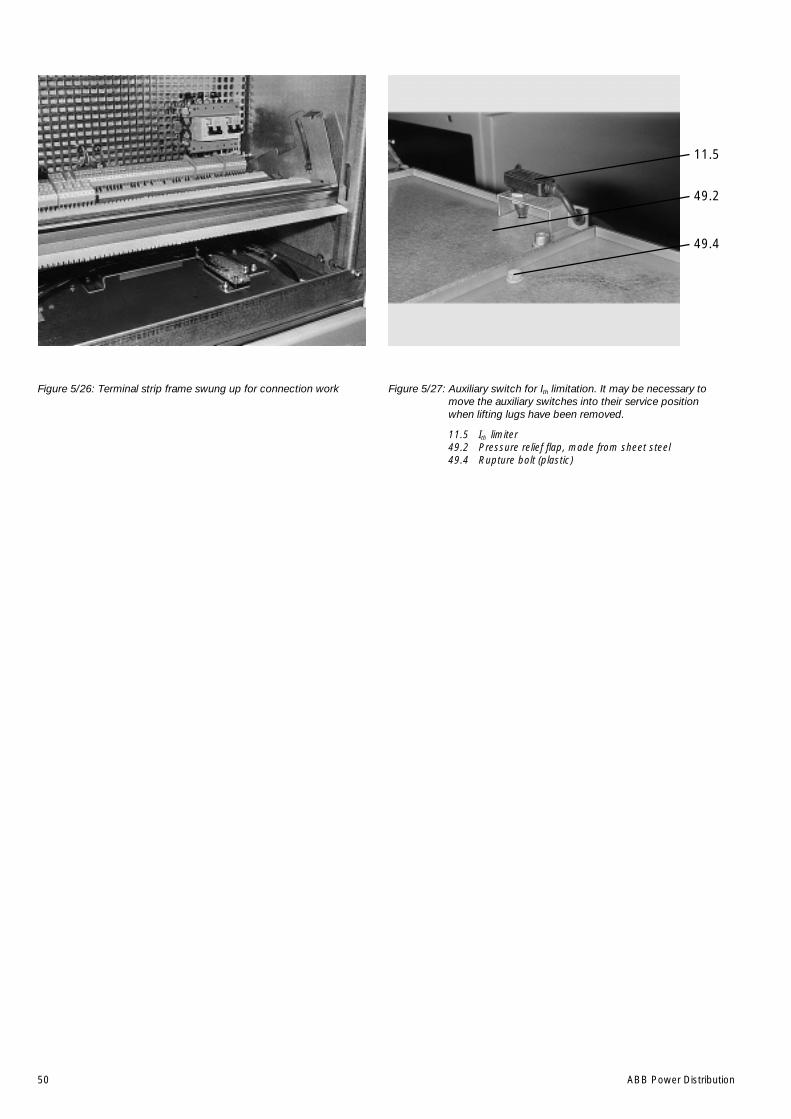
50 ABB Power Distribution
Figure 5/26: Terminal strip frame swung up for connection work Figure 5/27: Auxiliary switch for Ith limitation. It may be necessary tomove the auxiliary switches into their service positionwhen lifting lugs have been removed.
11.5 Ith limiter49.2 Pressure relief flap, made from sheet steel49.4 Rupture bolt (plastic)
11.5
49.2
49.4
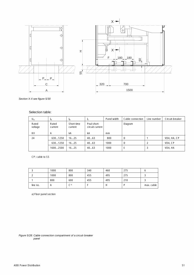
ABB Power Distribution 51
Section X-X see figure 5/30
Selection table:
UN IN Ith IS Panel width Cable connection Line number Circuit-breaker
Rated Rated Short time Peal short- Diagramvoltage current current circuit current
KV A kA kA mm
24 630...1250 16...25 40...63 800 D 1 VD4, HA, CP
630...1250 16...25 40...63 1000 D 2 VD4, CP
1600...2500 16...25 40...63 1000 E 3 VD4, HA
CP: cable to SS
3 1000 800 340 460 275 6
2 1000 800 455 495 275 3
1 800 600 455 495 210 3
line no. A Ca) F H P max. cable
a) Floor panel section
Figure 5/28: Cable connection compartment of a circuit-breakerpanel
F
60
55
X
X
320 700
180180
PP
A
C
1500
H
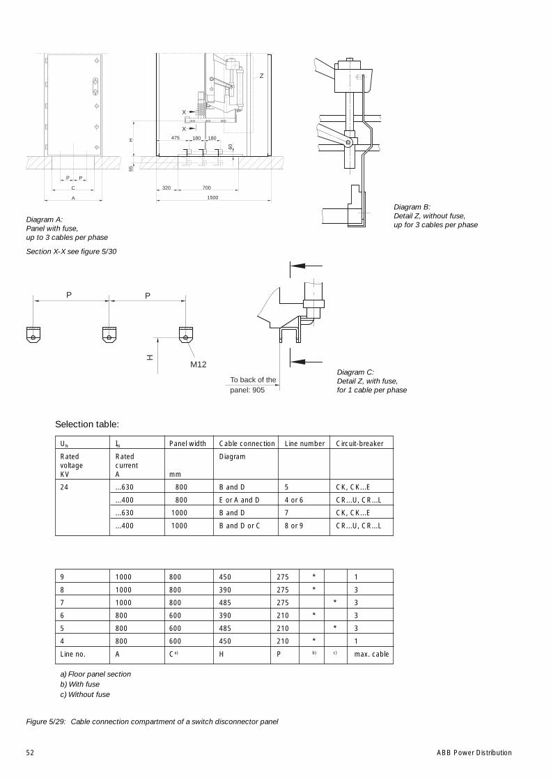
52 ABB Power Distribution
Selection table:
UN IN Panel width Cable connection Line number Circuit-breaker
Rated Rated Diagramvoltage currentKV A mm
24 ...630 800 B and D 5 CK, CK...E
...400 800 E or A and D 4 or 6 CR...U, CR...L
...630 1000 B and D 7 CK, CK...E
...400 1000 B and D or C 8 or 9 CR...U, CR...L
9 1000 800 450 275 * 1
8 1000 800 390 275 * 3
7 1000 800 485 275 * 3
6 800 600 390 210 * 3
5 800 600 485 210 * 3
4 800 600 450 210 * 1
Line no. A Ca) H P b) c) max. cable
a) Floor panel sectionb) With fusec) Without fuse
Figure 5/29: Cable connection compartment of a switch disconnector panel
Diagram B:Detail Z, without fuse,up for 3 cables per phase
Diagram A:Panel with fuse,up to 3 cables per phase
Section X-X see figure 5/30
Diagram C:Detail Z, with fuse,for 1 cable per phase
60
55X
X
320 700
180475 180
PP
A
C
1500
H
Z
H
P P
M12
To back of thepanel: 905
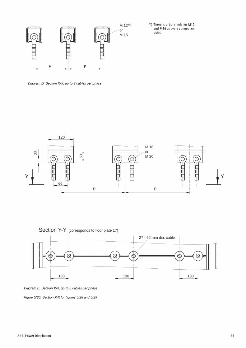
ABB Power Distribution 53
P P
M 12**orM 16
Section Y-Y (corresponds to floor plate 17)
27 - 62 mm dia. cable
120
66
YY
M 16orM 20
P P
60
25
130130130
Figure 5/30: Section X-X for figures 5/28 and 5/29
Diagram D: Section X-X, up to 3 cables per phase
Diagram E: Section X-X, up to 6 cables per phase
**) There is a bore hole for M12and M16 at every connectionpoint
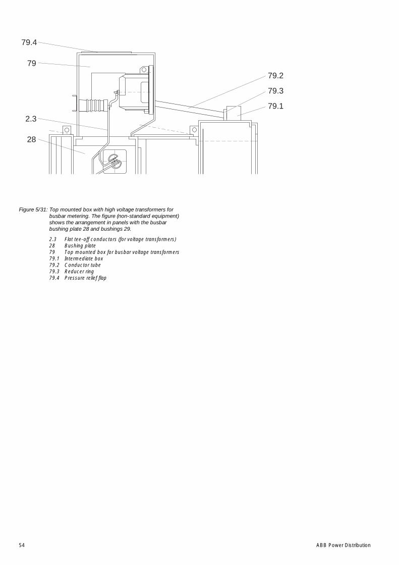
54 ABB Power Distribution
Figure 5/31: Top mounted box with high voltage transformers forbusbar metering. The figure (non-standard equipment)shows the arrangement in panels with the busbarbushing plate 28 and bushings 29.
2.3 Flat tee-off conductors (for voltage transformers)28 Bushing plate79 Top mounted box for busbar voltage transformers79.1 Intermediate box79.2 Conductor tube79.3 Reducer ring79.4 Pressure relief flap
79.4
79
2.3
28
79.2
79.3
79.1
ABB Power Distribution 55
6 Operation of the switchgearNote on safety at work
The relevant work and operating procedures are tobe carried out carefully by trained specialistsfamiliar with the installation, taking into a account allthe relevant safety regulations to DIN VDE/IEC andthe other relevant professional bodies, and otherlocal and work regulations and instructions. Specialattention is also to be paid to VDE 0105 (Operationof electrical installations).
Note:
Do not walk on the top surfaces of the switchgearpanels (rupture points for pressure relief).
6.1 Commissioning
6.1.1 Preparatory work
(Figures 3/12, 3/19)
In preparation for commissioning, the followingwork should be carried out prior to connection withthe high-voltage power supply:
• Check the general condition of the switchgearfor detrimental circumstances of all kinds.
• Perform a visual examination of the switchingdevices, withdrawable parts, isolating contacts,insulating parts, etc.
• Check the connection of the main earthing bar tothe station earthing conductor (observing therequirements of DIN VDE 0141).
• Check the paintwork for damage and touch upas described in section 7.4 where necessary.
• Remove all materials residues, foreign bodiesand tools from the switchgear.
• Clean the switchgear, rubbing down insulatingparts with a clean, soft, non-fraying and drycloth. Remove greasy or adhesive dirt asdescribed in section 7.3.
• Properly refit all covers etc. removed duringassembly and testing processes.
• Transport cabs 13.9 on vacuum circuit-breakers– if still fitted – must be removed.
• Pole tube lids 13.10 may be fitted in certainsystems and on certain circuit-breakers. Checktheir correct fit.
• Lifting lugs 13.13 on high current circuit-breakers must be removed if still fitted.
• Perform AC voltage testing of the main circuitsaccording to VDE 0670 part 6 (IEC 60298) as faras necessary. Pay special attention during thisprocedure to voltage transformers and cables,etc. A testing and earthing module 142 can beused to make the connections (see sections6.3.3).
• Switch the auxiliary and control voltage on.
• Carry out test operations of switching devicesmanually or by electrical control, andsimultaneously observe the relevant positionindicators.
• Check mechanical and electrical interlocks foreffectiveness, without using force.
• Set the protective devices in the switchgear tothe required values and check their function withtest equipment.
• In switchgear panels with an additional venti-lation system for high-current circuit-breakers(required for increased ambient temperature ->40 °C and/or higher frequency - 60Hz -according to section 1.3 and figure 6/21 and6/22) the flap 20.3 hanging in partition 20 mustloosely rest against leaf spring 20.4 (with thecentrifugal fan at a standstill - if fitted -).This is no standard.
To check:
– Insert a suitable screwdriver through opening20.5 in horizontal partition 20 and into bracket20.6 on flap 20.3.
– Swing flap 20.3 upwards and allow it to restloosely again on leaf spring 20.4.
– If the flap is in blocked position, use thescrewdriver to press leaf spring 20.4downwards by approx. 5mm to release theblock before swinging the flap.
– If any centrifugal fans controlled in relation toprimary current are fitted, also check that theyfunction correctly.
• On motorized withdrawable parts, check thedirection of rotation of the travel motor inaccordance with section 7.5.4.
• For any other questions on the function of thewithdrawable circuit-breaker part and testingfacilities for the withdrawable part, see section7.5.
• Instruct the local operators in the fundamentaldetails of regular handling of the switchgear.
• Check the readiness for operation and switchingstatus of electrical systems upstream anddownstream from the switchgear.
Depending on the allocation of responsibilities, itmay also be necessary to check the followingequipment in areas adjacent to the switchgear:
• power cables
• auxiliary cables
• auxiliary power source
• remote control system
• complete earthing system, to DIN VDE 0141
• switchroom equipment
• switchroom condition
56 ABB Power Distribution
6.1.2 Start-up
• Comply with all relevant safety regulations.
• Ensure that the circuit-breakers and switchdisconnectors in the system are in the OFFposition.
• Remove any existing earthing and shortcircuiting connections in the critical switchingarea.
• Energize the feeder cables.
• Connect the switchgear step by step, observingthe signals and indicators.
• Check that relevant conductors are in phase, asfar as necessary when several incoming feedercables and switchgear sections are concerned(see also section 6.3.2).
• Carry out all measurements and check allfunctions dependant on the high voltage powersupply being connected.
• Watch out for irregularities of any kind.
6.2 Switching operations
Carry out switching operations with the front doorsclosed.
6.2.1 Withdrawable circuit-breaker part
(Figures 6/1, 6/3, 6/5 to 6/11)
Manual insertion from the test/disconnectedposition to the service position:
• Connect control wiring plug 10.2
• Close the front door.
• Ensure that the circuit breaker is in the OFFposition.
• Fit hand crank 121 on square spigot 18.1 of thespindle mechanism 18.
• Turn the crank clockwise through approx. 30turns until the stop is reached and thewithdrawable part is in the service position.
• Observe the position indicator.
• Remove hand crank 121.
It has to be considered that the spring loaded pieceof scenery 18.2 will lie completely on the rear sideof the panel door when the hand crank will bemoved from the square spigot 18.1 of the spindlemechanism 18. This ensures that the rear part ofthe scenery has been shift on the hexagon cap ofthe spindle and prevents the unintentionalwrenching of the spindle during the service of thepanel. The wrenching may lead to a blocking of thecircuit-breaker.
Note:
The withdrawable part must not be stopped at anyposition in the travel range between the serviceposition and test/disconnected position!
Manual withdrawal from the service position intothe test/disconnected position:
• Ensure that the circuit-breaker is in the OFFposition.
• Reserve the procedure discribed above forinsertion into the service position.
Note:
Do not use force to move withdrawable parts withblocking magnet Y0 in the event of a voltage drop.If this occurs they are blocked along the wholetravel range between the service position and testposition. To remove the interlock, consult section7.5.5.
Motorized movement of the withdrawable part:
• Briefly operate the electrical control for insertionor withdrawal (the withdrawable part thenautomatically moves into the opposite position).
• Observe the position indicator.
Note:
When the drive motor is faulty, the withdrawablepart can be moved in the emergency manualoperation. If the drive motor fails during movementof the withdrawable part, the withdrawable partmust be moved into a limit position in emergencymanual operation.
Emergency manual operation is carried out withhand crank 121 on spindle mechanism 18, in asimilar manner to operation of a withdrawablebreaker part with manual systems. To disengagethe motorized withdrawable part, consult section7.5.1.
• Switch off the auxiliary power (m.c.b.), since themotor would otherwise be braked electrically.
• Turn hand crank 121 in the required direction.
When the withdrawable part moves, the motorturns. The motor functions in such a case like agenerator, i.e. it can lead to reserve voltages in theterminals.
The motor fuse must not be changed from thespecified type and rated value, otherwise thebehavior of the permanent magnet motor could beirreversibly impaired!
Caution.
In emergency manual operation of a motorizedwithdrawable circuit-breaker part, the interlockwith the earthing switch is not effective!
Withdrawal from the test/disconnection positiononto the service truck:
• Open the door of the circuit-breakercompartment.
• Release control wiring plug 10.2 and engage it inthe storage position on the withdrawable part.
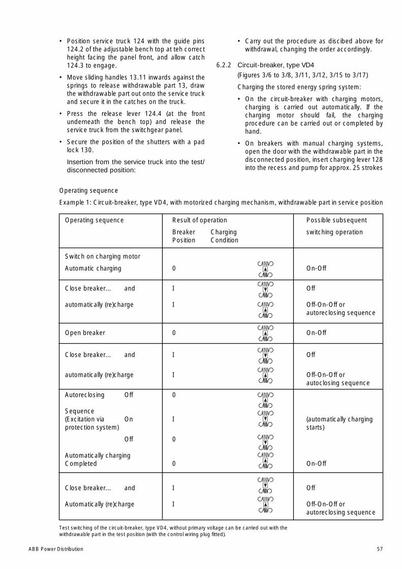
ABB Power Distribution 57
• Position service truck 124 with the guide pins124.2 of the adjustable bench top at teh correctheight facing the panel front, and allow catch124.3 to engage.
• Move sliding handles 13.11 inwards against thesprings to release withdrawable part 13, drawthe withdrawable part out onto the service truckand secure it in the catches on the truck.
• Press the release lever 124.4 (at the frontunderneath the bench top) and release theservice truck from the switchgear panel.
• Secure the position of the shutters with a padlock 130.
Insertion from the service truck into the test/disconnected position:
• Carry out the procedure as discibed above forwithdrawal, changing the order accordingly.
6.2.2 Circuit-breaker, type VD4
(Figures 3/6 to 3/8, 3/11, 3/12, 3/15 to 3/17)
Charging the stored energy spring system:
• On the circuit-breaker with charging motors,charging is carried out automatically. If thecharging motor should fail, the chargingprocedure can be carried out or completed byhand.
• On breakers with manual charging systems,open the door with the withdrawable part in thedisconnected position, insert charging lever 128into the recess and pump for approx. 25 strokes
Test switching of the circuit-breaker, type VD4, without primary voltage can be carried out with thewithdrawable part in the test position (with the control wiring plug fitted).
Operating sequence
Example 1: Circuit-breaker, type VD4, with motorized charging mechanism, withdrawable part in service position
Operating sequence Result of operation Possible subsequent
Breaker Charging switching operationPosition Condition
Switch on charging motor
Automatic charging 0 On-Off
Close breaker... and I Off
automatically (re)charge I Off-On-Off orautoreclosing sequence
Open breaker 0 On-Off
Close breaker... and I Off
automatically (re)charge I Off-On-Off orautoclosing sequence
Autoreclosing Off 0
Sequence(Excitation via On I (automatically chargingprotection system) starts)
Off 0
Automatically chargingCompleted 0 On-Off
Close breaker... and I Off
Automatically (re)charge I Off-On-Off orautoreclosing sequence
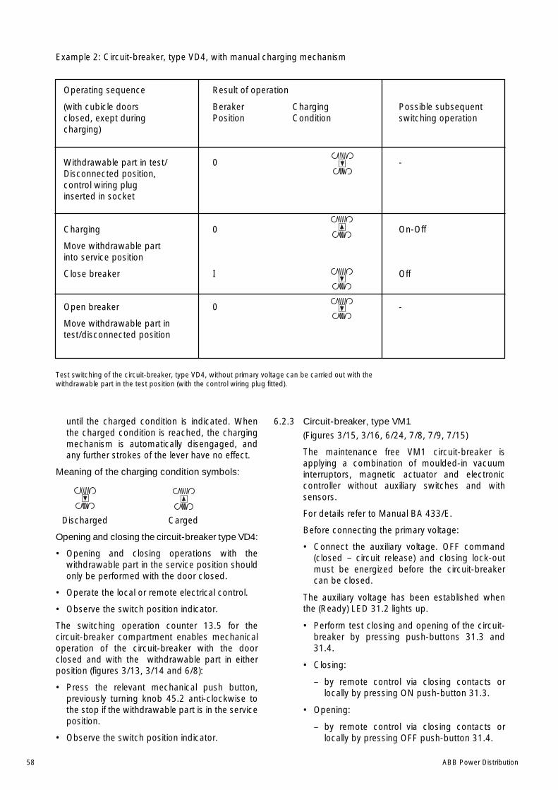
58 ABB Power Distribution
until the charged condition is indicated. Whenthe charged condition is reached, the chargingmechanism is automatically disengaged, andany further strokes of the lever have no effect.
Meaning of the charging condition symbols:
Discharged Carged
Opening and closing the circuit-breaker type VD4:
• Opening and closing operations with thewithdrawable part in the service position shouldonly be performed with the door closed.
• Operate the local or remote electrical control.
• Observe the switch position indicator.
The switching operation counter 13.5 for thecircuit-breaker compartment enables mechanicaloperation of the circuit-breaker with the doorclosed and with the withdrawable part in eitherposition (figures 3/13, 3/14 and 6/8):
• Press the relevant mechanical push button,previously turning knob 45.2 anti-clockwise tothe stop if the withdrawable part is in the serviceposition.
• Observe the switch position indicator.
6.2.3 Circuit-breaker, type VM1
(Figures 3/15, 3/16, 6/24, 7/8, 7/9, 7/15)
The maintenance free VM1 circuit-breaker isapplying a combination of moulded-in vacuuminterruptors, magnetic actuator and electroniccontroller without auxiliary switches and withsensors.
For details refer to Manual BA 433/E.
Before connecting the primary voltage:
• Connect the auxiliary voltage. OFF command(closed – circuit release) and closing lock-outmust be energized before the circuit-breakercan be closed.
The auxiliary voltage has been established whenthe (Ready) LED 31.2 lights up.
• Perform test closing and opening of the circuit-breaker by pressing push-buttons 31.3 and31.4.
• Closing:
– by remote control via closing contacts orlocally by pressing ON push-button 31.3.
• Opening:
– by remote control via closing contacts orlocally by pressing OFF push-button 31.4.
Example 2: Circuit-breaker, type VD4, with manual charging mechanism
Operating sequence Result of operation
(with cubicle doors Beraker Charging Possible subsequentclosed, exept during Position Condition switching operationcharging)
Withdrawable part in test/ 0 -Disconnected position,control wiring pluginserted in socket
Charging 0 On-Off
Move withdrawable partinto service position
Close breaker I Off
Open breaker 0 -
Move withdrawable part intest/disconnected position
Test switching of the circuit-breaker, type VD4, without primary voltage can be carried out with thewithdrawable part in the test position (with the control wiring plug fitted).
ABB Power Distribution 59
• Opening on failure of the auxiliary power supply:
– Electrical opening is still possible within thefirst 200 s.
– After a period of 200 s, emergency manualopening is necessary:
– Insert emergency manual operation lever31.28 onto the spigot of the emergency shaft31.9 in the front plate and turn it anticlockwiseto open the circuit-breaker.
Just before the final stop will be reached asmall resistance on the emergency shaft hasto be overcome.
• Closing on failure of the auxiliary power supply:
– Closing is not appropriate and not possible.
• After each operating cycle (ON-OFF), the operatingcycle counter 31.5 is incremented by one full digit.
On termination of a switching operation, theposition indicator 31.6 in the window of frontplate displays the relevant switch position.
• Anti-pumping system(see VDE 0101, section 5.2.3.2)
– The circuit-breaker controller ensures thatclosing of the circuit-breaker is blocked whenan opening command is active.
– When closing on a subsequent openingcommand, further closing with the still activeclosing command is blocked. The closingcommand must be issued again for the nextclosing operation.
6.2.4 Withdrawable metering parts
(Figures 3/1-6, 3/1-8, 3/18)
The handling of the withdrawable metering part inthe metering panel is as described in section 6.2.1,without however the switching operations andinterlocking functions.
Withdrawable metering parts in incoming andoutgoing feeder panels are inserted into the cablecompartment using a ramp. They reach theirservice position immediately and engage there inthe panel ground by means of the two locking pinsat the sides. The voltage transformers usedcorrespond to the type used in the metering panel,and therefore HRC fuses can also be used alongwith the voltage transformers.
6.2.5 Earthing switch, type EK6
(Figures 3/1, 6/12, 6/13, 6/25)
The earthing switch, type EK6, has a snap-actionclosing mechanism which is independant of therotation of the drive shaft. An earthing switch 6allocated to a circuit-breaker is only enabled forswitching when the withdrawable part 13 is in thetest/disconnected position or removed from the
switchgear panel. Only switch earthing switches onwhen the doors are closed.
Manual opening and closing:
• Press slide 14.2 on the operating lever recesssocket down. (When the switch is closed, it isalready in this position!)
• Fit operating lever 122 to hexagonal shaft14.1,which is now released for operation.
Note:
Put the operating lever 122 in such a way pointedupwards or downwards on the hexagonal shaftthat sufficient room for movement of the operatinglever remains even if space is constricted at thesides.
• Turn the lever clockwise through approx. 180°until the stop is reached to close the earthingswitch, or anti-clockwise until the stop isreached to open the earthing switch.
• Observe the mechanical/electrical switchposition indicator.
• Remove operating lever 122. Slide 14.2 remainsopen if the earthing switch is in the closedposition.
Make sure that the operating lever is turned right upto the stop in the opening process, to ensure thatthe earthing switch is in its defined limit position.The manual operating mechanism can also befitted with a blocking magnet.
Opening and closing with motorized operatingmechanism:
The earthing switch can also be fitted with amotorized operating mechanism.
• Briefly operate the electrical control for openingor closing. The earthing switch is then switchedautomatically into the opposite position.
Emergency manual operation:
If a fault should develop in the motorized operatingmechanism, the earthing switch can be switched inemergency manual operation with lever 122, in asimilar way to manually operated earthing switches.
Caution!
During emergency manual operation of amotorized earthing switch, the interlock is notfunctional!
On emergency manual operation, the coupling withthe motorized operating mechanism is auto-matically released. To disengage the coupling tothe motorized operating mechanism, first turn thelever 122 further in the preselected direction up tothe relevant stop (small angle of turn). On the nextoperation with the motorized mechanism after itsfunction has been restored, the coupling auto-matically engages again.

60 ABB Power Distribution
Note:
The lever may only be fitted temporarily forperformance of an emergency manual switchingoperation. The power to the motorized operatingmechanism must be switched off to the duration ofany breakdown.
6.2.6 Busbar earthing switch.
(Figures 3/1-4, 3/1-8, 3/22 to 3/25)
To earth the busbars, earthing switches, also oftype EK6, are used. Their operating mechanism isidentical with that of the tee-off earthing switches(see section 6.2.5).
The conditions for panel to panel interlocking of thebusbar earthing switches are described in section3.4.2.
6.2.7 Switch disconnector
Figure (3/1-9, 5/29, 6/13, 6/15)
Only operate switch disconnectors and earthingswitches when the panel doors are closed.
Notes:
• Fit operating lever 122 to the hexagon shaftpointing either upwards or downwards for eachswitching operation in such a way that it is notobstructed at the sides, even in limited space.
• Ensure that the lever is moved fully into the limitposition in all switching operations.
1. Opening an closing of a switch disconnectorwith snap action ON mechanism and snapaction OFF mechanism (Type CK 3):
– Close the switch disconnector by turning theoperating lever 122 clockwise throughapprox. 180° up to the stop, or open theswitch disconnector by turning the operatinglever anti-clockwise through approx. 189° upto the stop.
2. Opening and closing of a switch disconnectorwith snap action ON mechanism andrechargeable stored energy spring OFFmechanism (Type CK3):
– Close the switch disconnector by turning theoperating lever 122 clockwise throughapprox. 180° up to the stop.
– Recharge the stored energy springsimmediately after the closing operation byturning the lever through 180° in an anti-clockwise direction up to the stop.
The disconnector is then ready to open, alsoin response to fuse tripping, shunt andundervoltage releases.
– Open the switch disconnector by turning thelever clockwise through approx. 15°. Thenturn the lever back anti-clockwise until thestop is reached.
– Observe the switch position indicator (seealso section 6.2.9).
3. Opening and closing of a switch disconnectorwith snap action On Mechanism an storedenergy spring OFF mechanism (Type CS 3):
– Close the switch disconnector by turning theoperating lever 122 clockwise throughapprox. 180° up to the stop, or open theswitch disconnector by turning the operatinglever anti-clockwise through approx. 180° upto the stop. When the disconnector is thenready to open, it will also respond to fusetripping, shunt and undervoltage releases.
Special case:
Charge and engage the closing springs by turningthe lever anti-clockwise through approx. 180° up tothe stop (pretensioning).
This action is only required:
– on initial installation (stored energy springsthen normally discharged).
– for indirect operation (tripping by HRC fuse,shunt and undervoltage release).
4. Opening and closing an intergrated earthingswitch:
– Switching of a normally interlocked earthingswitch is only enabled when the switchdisconnector is in the open position.
– Turn the operating lever clockwise throughapprox. 180° to the stop to close the earthingswitch or anti-clockwise through approx.180° to the stop to open the earthing switch
– Observe the switch position indicator (seealso section 6.2.9).
5. Opening and closing with a motorizedmechanism:
Switch disconnectors and earthing switches canalso be fitted with motorized operatingmechanisms.
– Operate the electrical control to open/close theswitch (briefly), and the switch disconnector orearthing switch will then be switched auto-matically into the opposite position, or thestored-energy springs for the switchdisconnector charged.
Emergency manual operation:
If a fault develops in the motorized mechanism, theswitch disconnector and earthing switch can beoperate manually in emergencies with operatinglever 122, in a similar manner to a switch withmanual mechanism. To disengage the coupling tothe motorized operating mechanism, first turn thelever up to the relevant stop (small angle of turn).
On the next operation with the motorizedmechanism after its function gas been restored, thecoupling automatically reengages.
ABB Power Distribution 61
Note:
The lever may only be fitted temporarily forperformance of an emergency manual switchingoperation.
The power to the motorized operating mechanismmust be switched off for the duration of anybreakdown.
6.2.8 Insulating guard plate
(Figure 6/15)
With the isolating distance of the switchdisconnector open, an insulating guard plate canbe inserted into the relevant panel on rails.
Notes:
• Always clean an inspect insulating guard platesbefore use.
• When moisture and dirt cause layers of foreignmatter to build up on a guard plate, there isdanger due to possible leakage currents.
• Insulating guard plates are only suitable asprotection against accidental contact and not asprotection against reclosing.
• The service duration of inserted guard plates isfundamentally limited by the influence ofmoisture, temperature, contamination and theadjacency of live parts.
• Observe the details listed in section 7.2 and 7.3with regard to the insulating guard plates.
6.2.9 Electrical/mechanical display/monitoring
When the switchgear is in operation, observe all theoperating data and condition indications in thesecondary area.
Switch position indicator for switch disconnectors:
Use the opportunity to view the switch positionthrough the sight glass.
• Type CK3: The switch position is identical tothe mechanism position.
• Type CR3: Switch position indication is onlypossible with a separate display
• Type CS3: The switch position is identical tothe mechanism position whenoperation is direct.
For indirect operation (by fuse orelectrical release), the openingoperation results in differentpositions for the switch andmechanism.
6.2.10 Earthing and short-circuiting with earthing cablesets
(Figures 6/12, 6/16 to 6/20)
The relevant shutter 12.1 (12.2) is moved to theopen position with a withdrawable testing andearthing module 142.
This special withdrawable part is to be inserted in asimilar manner to a withdrawable circuit-breakerpart, using the same hand crank 121 after insertioninto the test/disconnected positions. The individualsteps of the earthing and short-circuiting processare as follows:
• Bolt the two actuating bars 142.1 to the requiredposition on the withdrawable testing andearthing module:
– At the bottom for opening of the top shutter.
– At the top for opening of the bottom shutter.
• Fit the isolating contacts to the testing andearthing module 142 at the required position:
– At the bottom to earth the cable area.
– At the top to earth the busbar area.
• Isolate the area to be earthed and secure againstreconnection.
• Carefully observe all relevant safety regulations.
• Remove the withdrawable circuit-breaker partfrom the relevant switchgear panel.
• Insert testing and earthing module 142 into thetest/disconnected position and move it fully intothe service position with hand crank 121.
• Check the area to be earthed for the off-circuitcondition, e.g. with voltage tester 125 inmeasuring sockets 30 respectively, or with ahigh-voltage tester on the relevant contacts142.7 in bushing 142.6 on module 142, or onthe cable connection.
• First firmly bolt the common earthing cable133.1 to earth terminal 19.3, and then useinsulated rod 133.3 to connect the conductorearthing cables 133.2 in a short-circuit-proofmanner to contact pins 142.7.
• Display earthing warning plate 135 on theswitchgear panel.
• Secure neighbouring live areas ( e.g. feedercables) to prevent inadvertent contact.

62 ABB Power Distribution
6.3 Test procedures
6.3.1 Testing the off-circuit conditon
(Figures 6/4, 6/16)
The panels are fitted with a capacitive voltageindication system including the corresponding(hand-held) plug-in indicator for testing of the off-circuit condition.
A distinction must be made between the lowresistance (LRM) system and the high resistance(HR) system. For further details, see draft standardVDE 0682 Part 415 or IEC 61243-5.
The two systems differ in several respects,including different voltage levels which constitutethe display thresholds. The capacitive voltagedividers installed in the panels are correspondinglyof different ratings, and the measuring sockets andindicators units are of different types.
Note:
The only permissible indicators are those whichsatisfy the requirements of the IEC and VDEstandards and correspond to the technical designof the indication system in the relevant switchgear !
The measuring sockets must on no account beshort-circuited, except for voltage tests on theswitchgear (e.g. at power frequency withstandvoltage and/or impulse voltage).
Testing for the off-circuit condition is effected usinga plug-in indicator at the corresponding socketpairs located among the controls on the panels.
Use of the indicator unit:
• Carry out a functional test on the unitimmediately before use, e.g. with interface testerKSP. The display must be clearly perceptible.
• The presence of operating voltage is displayedby a signal.
• Always follow the details given in the instructionsfor the particular indicator unit for yourswitchgear system.
Interface testing:
• Perform an interface test as a functional test onall coupling components, e.g. with interfacetester KSP.
• The interface test is a repeat test as specified inIEC 61243-5 and VDE 0682 Part 415.
6.3.2 Testing for in-phase condition
Testing for the in-phase condition, e.g. when thereis more than one incoming feeder, can be carriedout with a suitable phase comparator coupled tothe measuring sockets of the capacitive voltageindication system (if fitted).
Test procedure:
• Only use phase comparators which comply withthe IEC and VDE standards and are of suitabledesign for the indication system in the relevantswitchgear.
• Check the function of the unit immediately priorto use.
• Ensure that the maximum permissible length ofthe measuring cables for each phase is notexceeded.
• Connect the measuring cables to precisely thecorresponding main conductor sections.
• Follow the directions for the phase comparatorin detail!
6.3.3 Current and voltage testings
(Figures 6/4 , 6/16, 6/20)
Testing and earthing module 142 is available forthe performance of current and voltage tests. It isequally suitable for primary current injection to anycurrent transformers which may be fitted duringmeasurements in the protection circuit and, forexample, for the application of a test voltage duringinsulating testing.
• Isolate and secure the working area inaccordance with the safety regulations of DINVDE/IEC.
• For primary current feed, fasten the connectingcable of the test transformer to the contact pins142.7.
• For AC voltage tests, ball 142.4 on the contactpin is required. The bore in the ball serves forconnection of the voltage supply.
• For current tests, for example of smallconnected generators, the short-circuit bridge142.8 is to be fastened onto the contact pins.
Note:
With voltage tests at power frequency withstandvoltage and/or impulse voltage, observe thefollowing:
• Short-circuit the measuring sockets 30 in the re-levant panels for the duration of the testprocedure (only)!
• Disconnect any voltage transformers and coverwith an insulating plate.
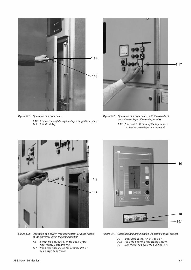
ABB Power Distribution 63
Figure 6/1: Operation of a door catch
1.18 Central catch of the high voltage compartment door145 Double bit key
Figure 6/2: Operation of a door catch, with the handle ofthe universal key in the turning position
1.17 Door catch, 90° turn of the key to openor close a low-voltage compartment
Figure 6/3: Operation of a screw-type door catch, with the handleof the universal key in the crank position
1.8 Screw-typ door catch, on the doors of thehigh-voltage compartments
147 Hand crank (for use on the central catch orscrew type door catch)
Figure 6/4: Operation and annunciation via digital control system
30 Measuring socket (LRM- System)30.1 Protection cover for measuring socket46 Bay control and protection unit REF542
1.17
46
30
30.1
1.8
147
1.18
145
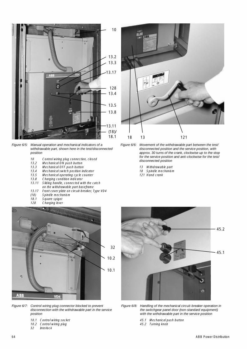
64 ABB Power Distribution
Figure 6/5: Manual operation and mechanical indicators of awithdrawable part, shown here in the test/disconnectedposition
10 Control wiring plug connection, closed13.2 Mechanical ON push button13.3 Mechanical OFF push button13.4 Mechanical switch position indicator13.5 Mechanical operating cycle counter13.8 Charging condition indicator13.11 Sliding handle, connected with the catch
on the withdrawable part baseframe13.17 Front cover plate on circuit-breaker, Type VD4(18) Spindle mechanism18.1 Square spigot128 Charging lever
Figure 6/8: Handling of the mechanical circuit-breaker operation inthe switchgear panel door (non-standard equipment)with the withdrawable part in the service position
45.1 Mechanical push button45.2 Turning knob
Figure 6/7: Control wiring plug connector blocked to preventdisconnection with the withdrawable part in the serviceposition
10.1 Control wiring socket10.2 Control wiring plug32 Interlock
Figure 6/6: Movement of the withdrawable part between the test/disconnected position and the service position, withapprox. 30 turns of the crank, clockwise up to the stopfor the service position and anti-clockwise for the test/disconnected position
13 Withdrawable part18 Spindle mechanism121 Hand crank
10
128
13.213.3
13.17
13.4
13.5
13.8
13.11(18)/18.1
32
10.2
10.1
45.1
45.2
1211318
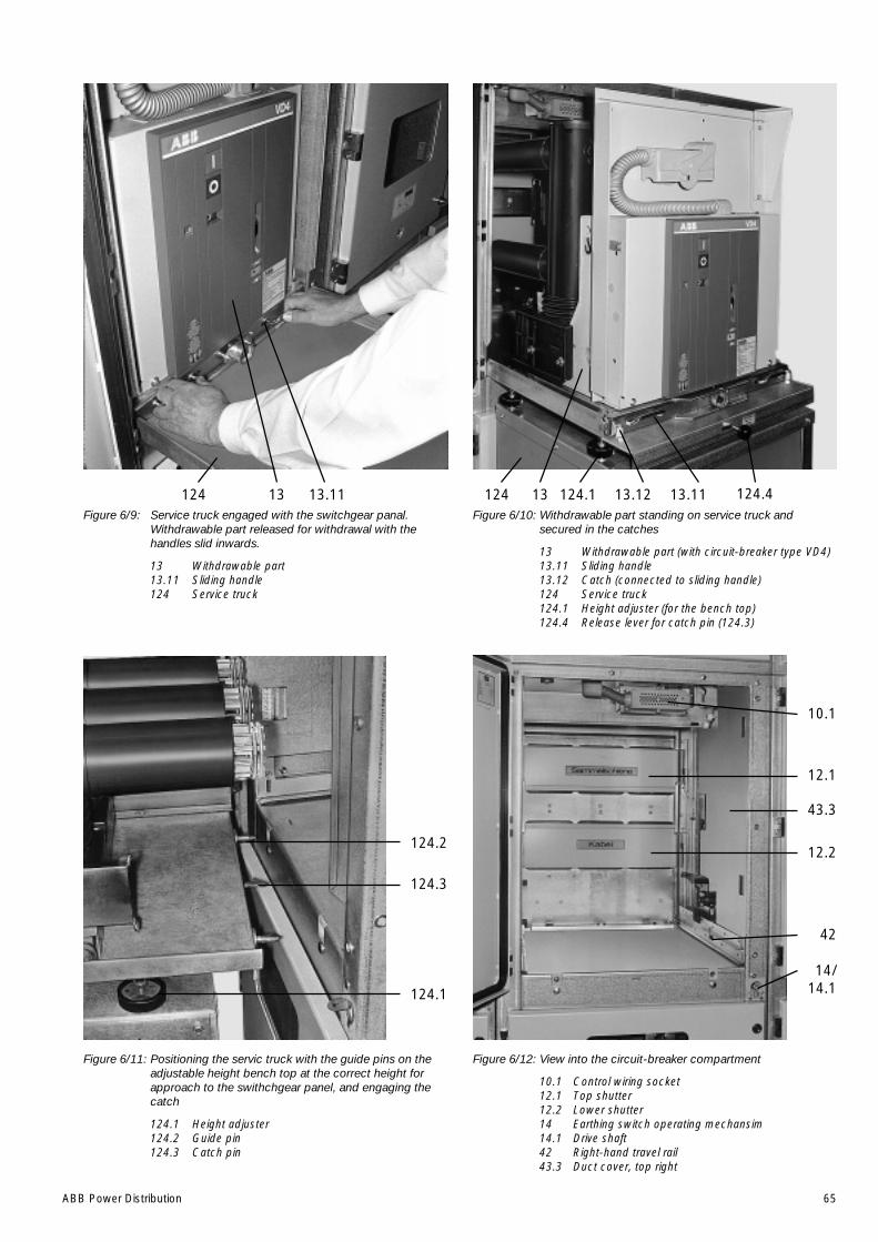
ABB Power Distribution 65
Figure 6/9: Service truck engaged with the switchgear panal.Withdrawable part released for withdrawal with thehandles slid inwards.
13 Withdrawable part13.11 Sliding handle124 Service truck
Figure 6/12: View into the circuit-breaker compartment
10.1 Control wiring socket12.1 Top shutter12.2 Lower shutter14 Earthing switch operating mechansim14.1 Drive shaft42 Right-hand travel rail43.3 Duct cover, top right
Figure 6/11: Positioning the servic truck with the guide pins on theadjustable height bench top at the correct height forapproach to the swithchgear panel, and engaging thecatch
124.1 Height adjuster124.2 Guide pin124.3 Catch pin
Figure 6/10: Withdrawable part standing on service truck andsecured in the catches
13 Withdrawable part (with circuit-breaker type VD4)13.11 Sliding handle13.12 Catch (connected to sliding handle)124 Service truck124.1 Height adjuster (for the bench top)124.4 Release lever for catch pin (124.3)
13.1113124 124.4124 13 124.1 13.1113.12
124.2
124.3
124.1
14/14.1
42
12.2
43.3
12.1
10.1

66 ABB Power Distribution
Figure 6/13: Preparation for operation of a switch disconnector and/or integrated earthing switch
1.10 Slot cover, for insulating guard plate(hinged and sping loaded)
35.1 Switch disconnector operating mechanism35.2 Earthing switch operating mechansim122 Operating lever
Figure 6/16: Fitting a (high-impedance) voltage indicator, type DSA2,manufacturer Pfisterer
30 Voltage measuring sockets30.1 Protective cover for measuring sockets125 Voltage indicator
Figure 6/15: Switchgear panel with switch disconnector and fuseassembly
1.10 Slot cover for insulating guard plate34 Switch disconnector35.1 Switch disconnector operating mechansim43.4 Duct cover for internal wiring160 HRC fuses
Figure 6/14: Preparation for operation of the tie-off earthing switchin a circuit-breaker panel
14 Earthing switch operathing mechansim14.1 Operating shaft for earhing switch14.2 Slide122 Operating lever
12530.1 30
1.10
122
35.1
35.2
122
14/14.1
14.2
1.10
34
35.1
160
43.4
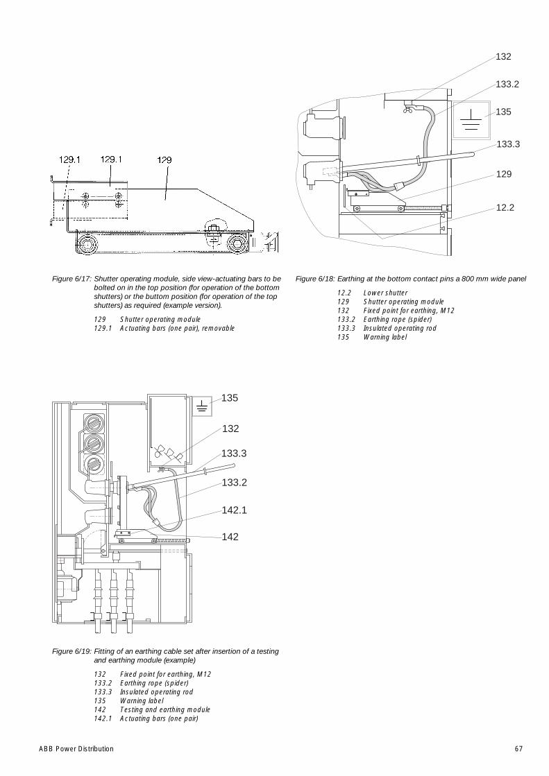
ABB Power Distribution 67
Figure 6/17: Shutter operating module, side view-actuating bars to bebolted on in the top position (for operation of the bottomshutters) or the buttom position (for operation of the topshutters) as required (example version).
129 Shutter operating module129.1 Actuating bars (one pair), removable
Figure 6/19: Fitting of an earthing cable set after insertion of a testingand earthing module (example)
132 Fixed point for earthing, M12133.2 Earthing rope (spider)133.3 Insulated operating rod135 Warning label142 Testing and earthing module142.1 Actuating bars (one pair)
Figure 6/18: Earthing at the bottom contact pins a 800 mm wide panel
12.2 Lower shutter129 Shutter operating module132 Fixed point for earthing, M12133.2 Earthing rope (spider)133.3 Insulated operating rod135 Warning label
12.2
133.3
135
129
132
133.2
142.1
132
135
133.2
133.3
142
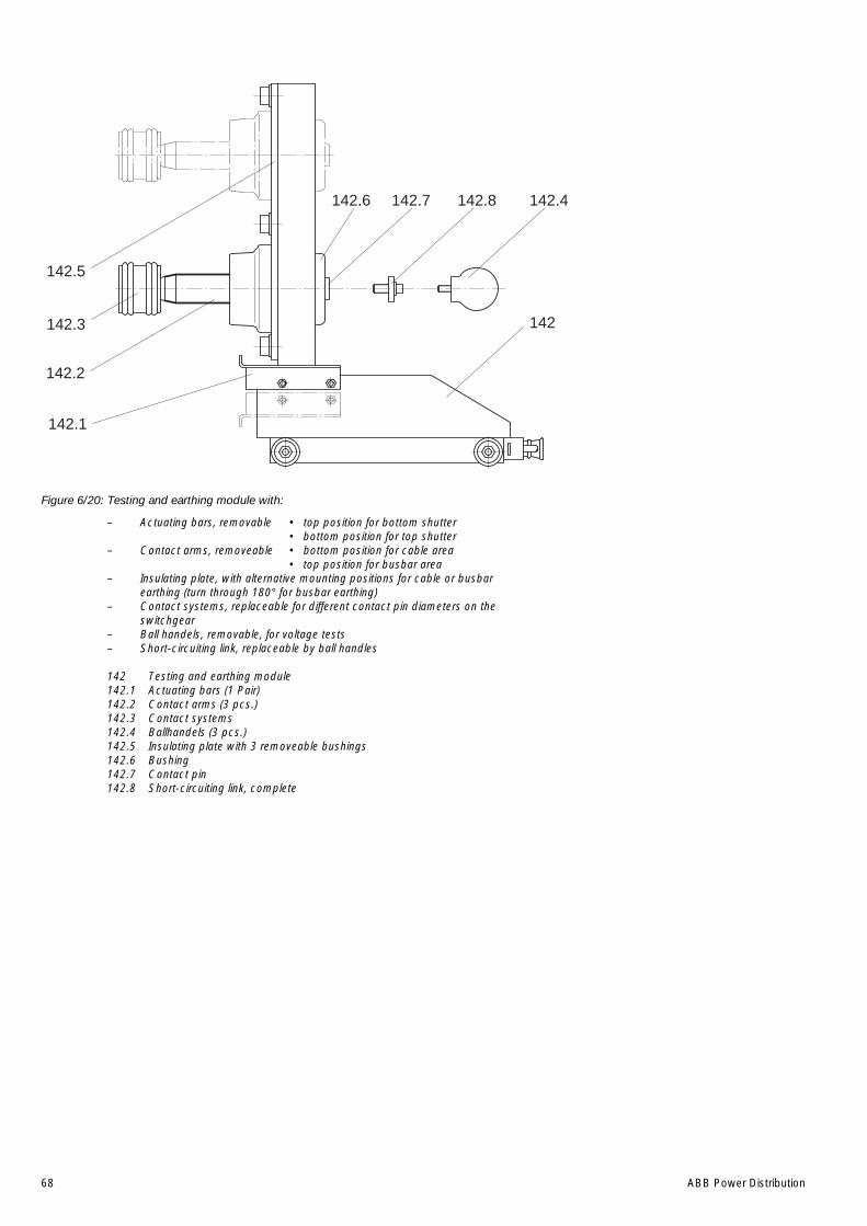
68 ABB Power Distribution
Figure 6/20: Testing and earthing module with:
– Actuating bars, removable • top position for bottom shutter• bottom position for top shutter
– Contact arms, removeable • bottom position for cable area• top position for busbar area
– Insulating plate, with alternative mounting positions for cable or busbarearthing (turn through 180° for busbar earthing)
– Contact systems, replaceable for different contact pin diameters on theswitchgear
– Ball handels, removable, for voltage tests– Short-circuiting link, replaceable by ball handles
142 Testing and earthing module142.1 Actuating bars (1 Pair)142.2 Contact arms (3 pcs.)142.3 Contact systems142.4 Ballhandels (3 pcs.)142.5 Insulating plate with 3 removeable bushings142.6 Bushing142.7 Contact pin142.8 Short-circuiting link, complete
142.3
142.2
142.1
142.5
142.6 142.7 142.8 142.4
142

ABB Power Distribution 69
Figure 6/21: Fitting of the horizontal partition 20 with additionalventilation for high current circuit-breakers required dueto increased ambient temperature ( > 40 °C ) and/orincreased frequency ( 60 Hz ) according to section 1.3.The internal flap is shown in the service position (open !).Side view, but without the wind vane with microswitchrequired with a fan. No Standard.
20 Horizontal partition, here fitted with additionalventilation facilities for the circuit-breaker
20.3 Flap20.4 Leaf spring20.5 Inspection opening20.6 Bracket20.7 Centrifugal fan
Figure 6/22: Horizontal partition with additional ventilation facilitieschecking of unimpeded motion of the internal flap (20.3)
20.5 Inspection opening
20.5
Figure 6/23: Lower shutter secured with padlock to preventunauthorized operation
38 Lever for shutter operation130 Padlock (customer component)
Figure 6/24: Manual emergency – OFF operation of the VM1 vacuumcircuit-breaker with magnetic actuator
31.28 Emergency manual opening lever (for switching offcircuit-breaker, type VM1)
Note:On the operation with the emergency operation lever31.28 there has to overcome a mechanical resistanceafter the tension of the auxiliary spring 31.29 and at theend of the turning motion.
38 130
31.28
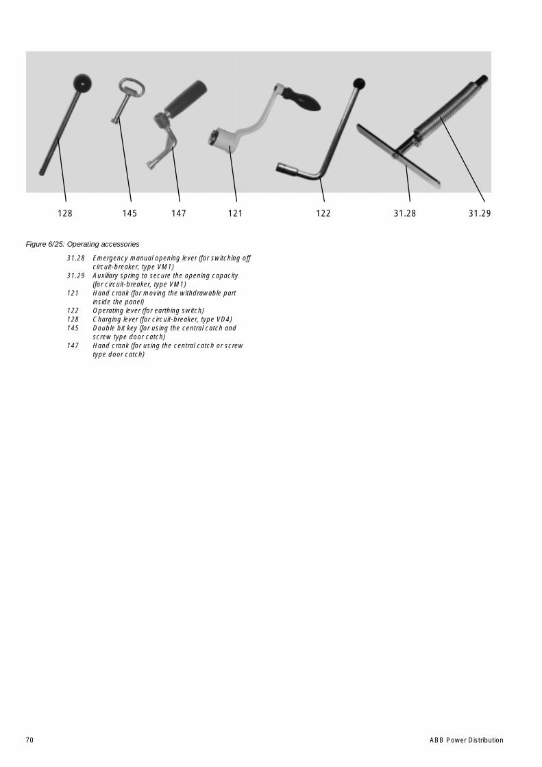
70 ABB Power Distribution
Figure 6/25: Operating accessories
31.28 Emergency manual opening lever (for switching offcircuit-breaker, type VM1)
31.29 Auxiliary spring to secure the opening capacity(for circuit-breaker, type VM1)
121 Hand crank (for moving the withdrawable partinside the panel)
122 Operating lever (for earthing switch)128 Charging lever (for circuit-breaker, type VD4)145 Double bit key (for using the central catch and
screw type door catch)147 Hand crank (for using the central catch or screw
type door catch)
128 145 147 121 122 31.28 31.29
ABB Power Distribution 71
7 Maintenance
7.1 General
Maintenance serves to preserve trouble-freeoperation and achieve the longest possible workinglife of the switchgear. In accordance with DIN 31051, it comprises the following closely relatedactivities:
Inspection: Determination of the actual condition
Servicing: Measures to preserve the specifiedcondition
Repair: Measures to restore the specifiedcondition
Note:
When carrying out all maintenance work, theregulations in the country of installation must bestrictly complied with. In Germany these comprisethe following safety regulations and standards:
– Health and safety at work standard VBG 1
– Health and safety at work standard VBG 4
– VDE 0105 "Operation of electrical installations”
Maintenance work may only be performed in acareful manner by trained personnel familiar withthe characteristics the individual switchgear, inaccordance with all relevant safety regulations toVDE/IEC and of other technical authorities, andwith other overriding instructions. It is recommendedthat ABB service personnel be called in to performservicing and repair work detailed below.
The inspection and servicing intervals for some ofthe equipment/components (e.g. parts subjects towear) are determined by fixed criteria such asswitching frequency, length of service and numberof short-circuit breaking operations. For otherparts, on the other hand, the length of the intervalsmay depend, for example, on the different modesof operation in individual cases, the degree ofloading, and also environmental influences(including pollution and aggressive air).
The following operating instructions must also beobserved together with this instruction manual inthe individual cases concerned:
Vacuum circuit-breakerType VD4 BA 352E
Vacuum circuit-breakerType VD4E BA 377E
Vacuum circuit-breakerType VD4- high-current BA 359E
Vacuum circuit-breaker withmagnetic actuator mechanismTyp VM1 BA 433E
Earthing switchType EK6 BA 304E
Rod-type switch disconnectorType C3 BA 275E
If necessary, further details can be taken from thetechnical documentation for the switchgearinstallation (including, for example, any agreedspecial operating conditions).
7.2 Inspection
• Before inspection, where required, the workingarea must be isolated and secured againstreconnection in accordance with the “SafetyRegulations” specified by DIN VDE/IEC.
• Proper condition of the switchgear should bemonitored by regular inspections.
• Under normal operating conditions, inspectionshould be conducted once every four years byspecially trained professional electricians.
• Under unusual operating conditions (includingadverse climatic conditions) and/or peculiar en-vironmental stresses (among other strongpollution and aggressive atmosphere),inspection may be necessary at shorterintervals.
• Inspection is primarily to constitute a visualcheck for grime, corrosion and moisture:
– Effects of high temperature on the maincircuits,
– Traces of partial discharge on the insulatingmaterial parts,
– Traces of leakage current on the insulatingmaterial parts,
– Surfaces of the contact systems.
• However, inspection is also to include the propermechanical/electrical function of the followingfacilities: switching devices, actuating,interlocking, protection and signalling facilities.
Special conditions:
• On panels with additional ventilation devices dueto increased ambient temperature (see alsosection 1.3):
1. Check flap 20.3 for correct function. (See alsosection 6.1.1 and figures 6/21 and 6/22.)
2. The centrifugal fan (if fitted) doesn’t requireany special maintenance. Its working life,depending on the service conditions - onesignificant parameter being the roomtemperature - is approx. 20,000 to 30,000operating hours.
Checking of the readiness for operation canbe carried out as follows:
a) Load-dependent functional test withcontrollable primary current injection of the re-levant instrument transformer. At current rise:
72 ABB Power Distribution
1. to approx. 70% of the rated instrumenttransformer current, the fan must start,
and
2.to 80 % of the rated instrumenttransformer current, the fan must havereached the required minimum air flow.Corresponding monitoring/signalling bythe wind vane with microswitch.
b) Basic checking with temporary operation ofthe centrifugal fan with an external powersupply of 220 V AC.
c) In both cases, check for unimpeded normalrunning of the fan and listen for any unusualbearing noise. Remove any dirt on the fanrotor.
d) Check the unimpeded function of the windvane and microswitch by starting the fanseveral times.
e) The wiring to the removable horizontalpartition 20 can be disconnected behindthe right-hand side duct cover 43.4 (figure5/12). Observe the circuit diagram andcarefully reconnect the wiring oncompletion.
Caution: instrument transformer circuit.
• With regard to the switching devices, their sepa-rate Instruction manual should be observed.
• Check all switchgear accessories and auxiliaryfacilities (e.g. storage batteries).
• No external discharge may occur on thesurfaces of equipment at operating voltage. Thiscan, for example, be detected by characteristicnoises, a clearly perceptible smell of ozone, orvisible glowing in the dark.
• Visual checking of the contact system. Werecommend to turn alternately the contactsystem in order to clean the inner contact pointsof the contact system.
The contact points should be cleaned if signs ofunperminable overheating (discoloured surface)are visible (see section 7.4).
• If irregular conditions are detected, then cor-responding repair measures should be initiated.
7.3 Servicing
If, on the occasion of an inspection in accordancewith section 7.2, the necessity of cleaningmeasures has been established, proceed asfollows:
• Before cleaning, where required, the workingarea must be switched off and secured againstreconnection in accordance with the “SafetyRegulations” specified by DIN VDE/IEC.
• Cleaning the surfaces in general:
– Weakly adhering dry dust deposits with a softdry cloth.
– More strongly adhering grime with mildlyalkaline household cleanser or with RivoltaBWR 210.
• Cleaning insulating surfaces and conductivecomponents:
– Minor pollution with Rivolta BWR 210.
– Strongly adhering pollution with Cold cleanser716.
• Observe the manufacturers’ directions and inparticular ABB Instruction manual BA 1002/Eand BA 1006/E on safety at work.
• Wipe down after cleaning, using clean water,and dry properly.
• Should external discharges occur as a result ofcondensation, application of a thin silicone filmon the surface concerned is often effective as atemporary remedy. It is advisable to requestadvice from the ABB after-sales servicedepartment on permanent solutions to suchunusual problems.
7.4 Repair
7.4.1 Switchgear in general
Repair of surface damage:
• Carry out repair work immediately after a defecthas been discovered.
• Completely remove all rust from damaged paint-work areas on steel sheet and other steel partsby mechanical means, e.g. with a wire brush.
• Lightly grind the surrounding paint coat andcarefully degrease the entire area. Thenimmediately apply an anti-rust primer and, afteran appropriate hardening time, apply the topcoat. Only use suitable and compatible paintproducts.
Apply the top coat in standard colour RAL 7035,or the relevant special colour.
• Carefully remove any white rust on aluminium/zinc surfaces with a wire brush or cleaning pad,e.g. Scotch-Brite, and clean loosely adheringparticles with a dry, non-fraying cloth. Next treatthe cleaned parts with zinc spray or zinc dustpaint and, finally, treat with aluminium spray forcolour matching.
• Carefully remove any white rust from passivatedfunctioning parts and rust formation onphosphatised parts with a wire brush or metal-free cleaning pad, e.g. Scotch-Brite, and cleanwith a dry cloth. Then grease evenly (with IsoflexTopas NB 52).
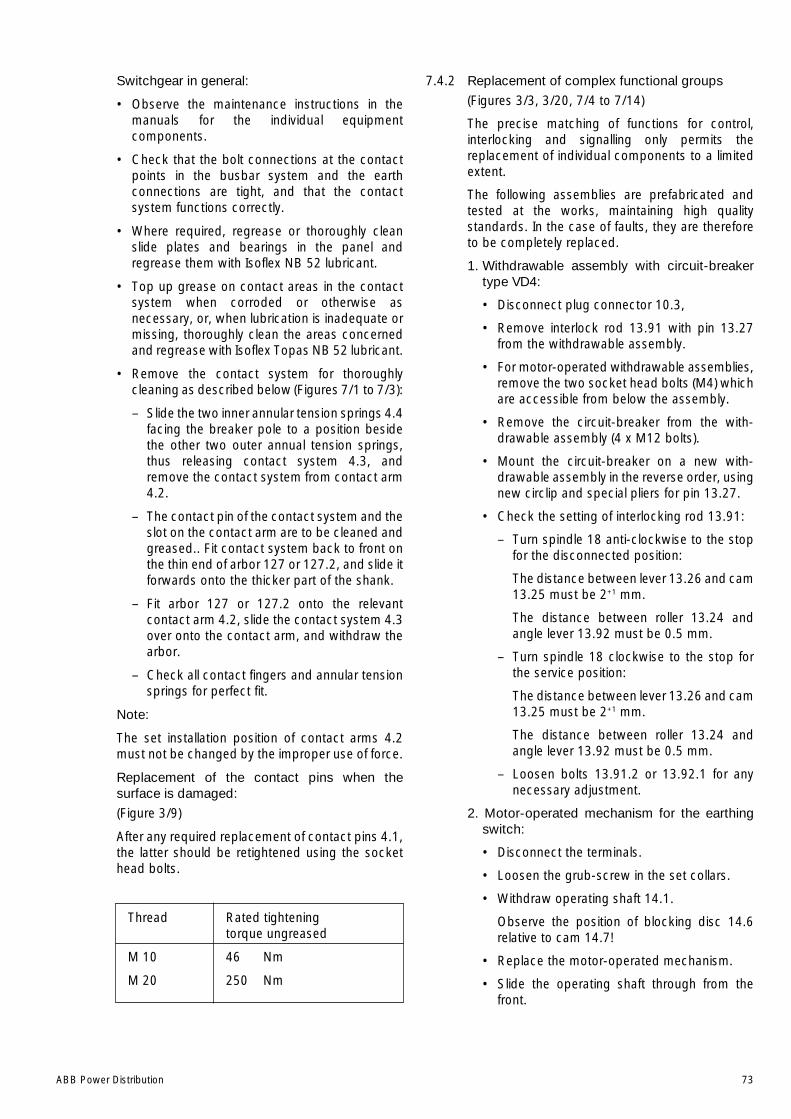
ABB Power Distribution 73
Switchgear in general:
• Observe the maintenance instructions in themanuals for the individual equipmentcomponents.
• Check that the bolt connections at the contactpoints in the busbar system and the earthconnections are tight, and that the contactsystem functions correctly.
• Where required, regrease or thoroughly cleanslide plates and bearings in the panel andregrease them with Isoflex NB 52 lubricant.
• Top up grease on contact areas in the contactsystem when corroded or otherwise asnecessary, or, when lubrication is inadequate ormissing, thoroughly clean the areas concernedand regrease with Isoflex Topas NB 52 lubricant.
• Remove the contact system for thoroughlycleaning as described below (Figures 7/1 to 7/3):
– Slide the two inner annular tension springs 4.4facing the breaker pole to a position besidethe other two outer annual tension springs,thus releasing contact system 4.3, andremove the contact system from contact arm4.2.
– The contact pin of the contact system and theslot on the contact arm are to be cleaned andgreased.. Fit contact system back to front onthe thin end of arbor 127 or 127.2, and slide itforwards onto the thicker part of the shank.
– Fit arbor 127 or 127.2 onto the relevantcontact arm 4.2, slide the contact system 4.3over onto the contact arm, and withdraw thearbor.
– Check all contact fingers and annular tensionsprings for perfect fit.
Note:
The set installation position of contact arms 4.2must not be changed by the improper use of force.
Replacement of the contact pins when thesurface is damaged:
(Figure 3/9)
After any required replacement of contact pins 4.1,the latter should be retightened using the sockethead bolts.
Thread Rated tighteningtorque ungreased
M 10 46 Nm
M 20 250 Nm
7.4.2 Replacement of complex functional groups
(Figures 3/3, 3/20, 7/4 to 7/14)
The precise matching of functions for control,interlocking and signalling only permits thereplacement of individual components to a limitedextent.
The following assemblies are prefabricated andtested at the works, maintaining high qualitystandards. In the case of faults, they are thereforeto be completely replaced.
1. Withdrawable assembly with circuit-breakertype VD4:
• Disconnect plug connector 10.3,
• Remove interlock rod 13.91 with pin 13.27from the withdrawable assembly.
• For motor-operated withdrawable assemblies,remove the two socket head bolts (M4) whichare accessible from below the assembly.
• Remove the circuit-breaker from the with-drawable assembly (4 x M12 bolts).
• Mount the circuit-breaker on a new with-drawable assembly in the reverse order, usingnew circlip and special pliers for pin 13.27.
• Check the setting of interlocking rod 13.91:
– Turn spindle 18 anti-clockwise to the stopfor the disconnected position:
The distance between lever 13.26 and cam13.25 must be 2+1 mm.
The distance between roller 13.24 andangle lever 13.92 must be 0.5 mm.
– Turn spindle 18 clockwise to the stop forthe service position:
The distance between lever 13.26 and cam13.25 must be 2+1 mm.
The distance between roller 13.24 andangle lever 13.92 must be 0.5 mm.
– Loosen bolts 13.91.2 or 13.92.1 for anynecessary adjustment.
2. Motor-operated mechanism for the earthingswitch:
• Disconnect the terminals.
• Loosen the grub-screw in the set collars.
• Withdraw operating shaft 14.1.
Observe the position of blocking disc 14.6relative to cam 14.7!
• Replace the motor-operated mechanism.
• Slide the operating shaft through from thefront.
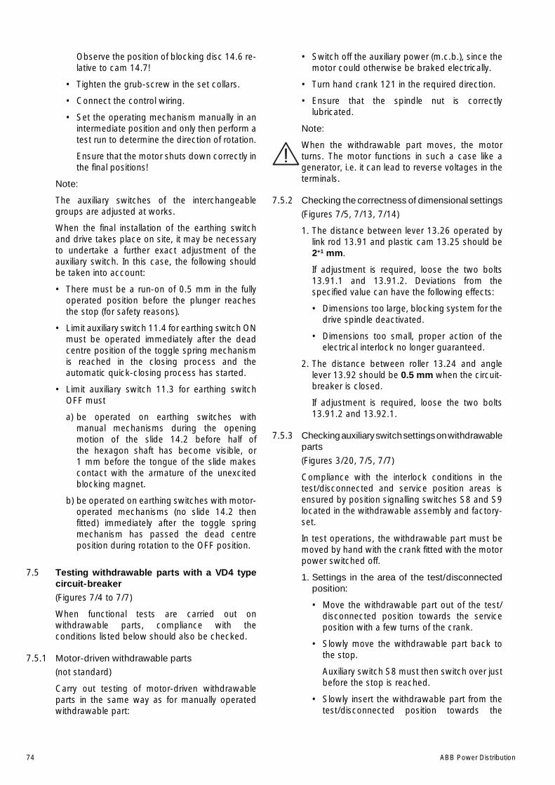
74 ABB Power Distribution
Observe the position of blocking disc 14.6 re-lative to cam 14.7!
• Tighten the grub-screw in the set collars.
• Connect the control wiring.
• Set the operating mechanism manually in anintermediate position and only then perform atest run to determine the direction of rotation.
Ensure that the motor shuts down correctly inthe final positions!
Note:
The auxiliary switches of the interchangeablegroups are adjusted at works.
When the final installation of the earthing switchand drive takes place on site, it may be necessaryto undertake a further exact adjustment of theauxiliary switch. In this case, the following shouldbe taken into account:
• There must be a run-on of 0.5 mm in the fullyoperated position before the plunger reachesthe stop (for safety reasons).
• Limit auxiliary switch 11.4 for earthing switch ONmust be operated immediately after the deadcentre position of the toggle spring mechanismis reached in the closing process and theautomatic quick-closing process has started.
• Limit auxiliary switch 11.3 for earthing switchOFF must
a) be operated on earthing switches withmanual mechanisms during the openingmotion of the slide 14.2 before half ofthe hexagon shaft has become visible, or1 mm before the tongue of the slide makescontact with the armature of the unexcitedblocking magnet.
b) be operated on earthing switches with motor-operated mechanisms (no slide 14.2 thenfitted) immediately after the toggle springmechanism has passed the dead centreposition during rotation to the OFF position.
7.5 Testing withdrawable parts with a VD4 typecircuit-breaker(Figures 7/4 to 7/7)
When functional tests are carried out onwithdrawable parts, compliance with theconditions listed below should also be checked.
7.5.1 Motor-driven withdrawable parts
(not standard)
Carry out testing of motor-driven withdrawableparts in the same way as for manually operatedwithdrawable part:
• Switch off the auxiliary power (m.c.b.), since themotor could otherwise be braked electrically.
• Turn hand crank 121 in the required direction.
• Ensure that the spindle nut is correctlylubricated.
Note:
When the withdrawable part moves, the motorturns. The motor functions in such a case like agenerator, i.e. it can lead to reverse voltages in theterminals.
7.5.2 Checking the correctness of dimensional settings
(Figures 7/5, 7/13, 7/14)
1. The distance between lever 13.26 operated bylink rod 13.91 and plastic cam 13.25 should be2+1 mm.
If adjustment is required, loose the two bolts13.91.1 and 13.91.2. Deviations from thespecified value can have the following effects:
• Dimensions too large, blocking system for thedrive spindle deactivated.
• Dimensions too small, proper action of theelectrical interlock no longer guaranteed.
2. The distance between roller 13.24 and anglelever 13.92 should be 0.5 mm when the circuit-breaker is closed.
If adjustment is required, loose the two bolts13.91.2 and 13.92.1.
7.5.3 Checking auxiliary switch settings on withdrawableparts
(Figures 3/20, 7/5, 7/7)
Compliance with the interlock conditions in thetest/disconnected and service position areas isensured by position signalling switches S8 and S9located in the withdrawable assembly and factory-set.
In test operations, the withdrawable part must bemoved by hand with the crank fitted with the motorpower switched off.
1. Settings in the area of the test/disconnectedposition:
• Move the withdrawable part out of the test/disconnected position towards the serviceposition with a few turns of the crank.
• Slowly move the withdrawable part back tothe stop.
Auxiliary switch S8 must then switch over justbefore the stop is reached.
• Slowly insert the withdrawable part from thetest/disconnected position towards the

ABB Power Distribution 75
service position until auxiliary switch S8 justoperates.
In this position, it must still just be possible tomove closing push rod 13.2.1. For this test,the function of the blocking magnet Y0 mustbe deactivated manually.
This condition ensures that the electricalinterlock takes effect before the mechanicalinterlock in the motion sequence involved.
2. Settings in the area of the service position:
• Move the withdrawable part out of the limitposition towards the test/disconnectedposition with a few turns of the crank.
• Slowly move the withdrawable part forwardsagain to the stop.
Auxiliary switch S9 must then switch over justbefore the stop is reached.
7.5.4 Checking the direction of rotation of the travelmotors on motor-driven withdrawable parts
• Move the withdrawable part by hand into acentral position between the test/disconnectedposition and the service position.
• Remove the hand crank.
• Switch the auxiliary voltage for the travel motoron.
• Use the local electrical controls to check that thewithdrawable part moves in the correctdirection.
Caution:
Do not allow the withdrawable part to run upagainst a block when the travel direction isincorrect! Switch the motor power off immediately(the travel process functions electrically by a seal-insystem with limit position switch-off).
There may be a danger of injury when the door isopen!
7.5.5 Testing of interlock conditions
(Figures 3/7, 3/20, 6/5 to 6/7, 7/7, 7/10)
1. The withdrawable part must only be movablefrom the test/disconnected position into theservice position when the circuit-breaker is openand the earthing switch is open.
Check the following conditions individually:
• With the circuit-breaker closed, insertion ofthe withdrawable part towards the serviceposition must be blocked after only half a turnof the crank in the clockwise direction, andthe travel motor on motor-operatedwithdrawable parts must not be capable ofbeing switched on.
• With the earthing switch closed, insertion of
the withdrawable part towards the serviceposition must be blocked after only twoclockwise turns of the crank, and the travelmotor on motor-operated parts must not becapable of being switched on.
Use no force!
2. The withdrawable part must only be movablefrom the service position into the test/disconnected position with the circuit-breakeropen.
Check this condition as follows:
• With the circuit-breaker closed, withdrawalmovement of the withdrawable part must beblocked after only half a turn of the crank inanti-clockwise direction, and the travel motoron motor-operated withdrawable parts mustnot be capable of being switched on.
3. Closing of the circuit-breaker must only bepossible when the withdrawable part is in thedefined test/disconnected position or serviceposition.
The control wiring plug 10.2 must previouslyhave been inserted.
Check this condition as follows:
• It must not be possible to close the circuit-breaker with the withdrawable part in anyposition between the test/disconnectedposition and the service position.
Enabling of switching when the withdrawablepart moves into the service position iseffected electrically by operation of auxiliaryswitch S9 in the withdrawable assembly, andmechanically slightly earlier; the lattercorresponds to a position approximately halfa turn of the crank before stop.
• For motion into the test/disconnectedposition, the same enabling conditions applyanalogously, in this case by means of auxiliaryswitch S8 in the withdrawably assembly.
4. It must only be possible to open the circuit-breaker (manually) when the withdrawable partis in the service position or test/disconnectedposition and the control voltage has failed.
Check this condition.
5. Withdrawable parts with order-related blockingmagnet Y0 may not be moved in case of controlpower failure, or when there is no control power.Do not forcibly move blocked withdrawableparts! The blocking magnet Y0 is only present onmanually operated withdrawable parts.
Releasing the blocking magnet Y0:
• Remove front plate 13.17,
• Disengage blocking magnet Y0 by pulling themagnet armature,
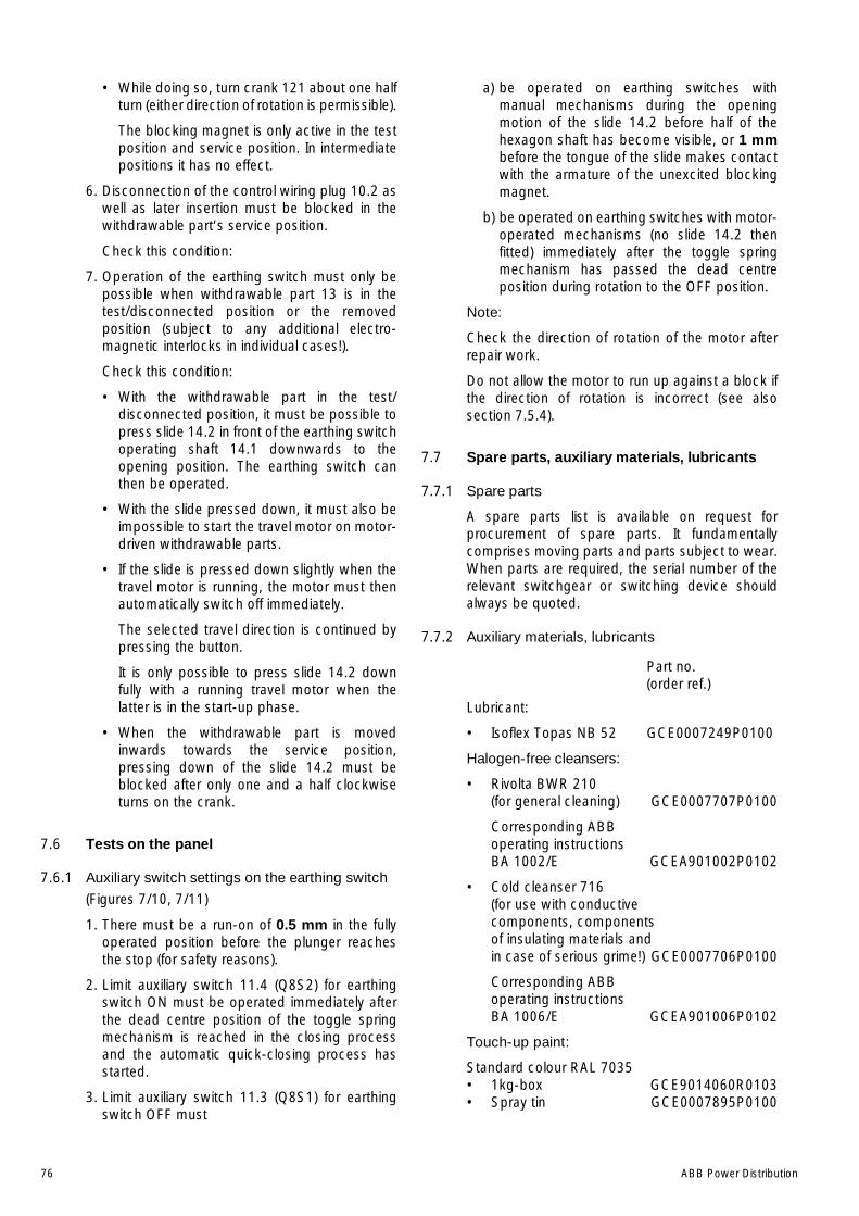
76 ABB Power Distribution
• While doing so, turn crank 121 about one halfturn (either direction of rotation is permissible).
The blocking magnet is only active in the testposition and service position. In intermediatepositions it has no effect.
6. Disconnection of the control wiring plug 10.2 aswell as later insertion must be blocked in thewithdrawable part‘s service position.
Check this condition:
7. Operation of the earthing switch must only bepossible when withdrawable part 13 is in thetest/disconnected position or the removedposition (subject to any additional electro-magnetic interlocks in individual cases!).
Check this condition:
• With the withdrawable part in the test/disconnected position, it must be possible topress slide 14.2 in front of the earthing switchoperating shaft 14.1 downwards to theopening position. The earthing switch canthen be operated.
• With the slide pressed down, it must also beimpossible to start the travel motor on motor-driven withdrawable parts.
• If the slide is pressed down slightly when thetravel motor is running, the motor must thenautomatically switch off immediately.
The selected travel direction is continued bypressing the button.
It is only possible to press slide 14.2 downfully with a running travel motor when thelatter is in the start-up phase.
• When the withdrawable part is movedinwards towards the service position,pressing down of the slide 14.2 must beblocked after only one and a half clockwiseturns on the crank.
7.6 Tests on the panel
7.6.1 Auxiliary switch settings on the earthing switch
(Figures 7/10, 7/11)
1. There must be a run-on of 0.5 mm in the fullyoperated position before the plunger reachesthe stop (for safety reasons).
2. Limit auxiliary switch 11.4 (Q8S2) for earthingswitch ON must be operated immediately afterthe dead centre position of the toggle springmechanism is reached in the closing processand the automatic quick-closing process hasstarted.
3. Limit auxiliary switch 11.3 (Q8S1) for earthingswitch OFF must
a) be operated on earthing switches withmanual mechanisms during the openingmotion of the slide 14.2 before half of thehexagon shaft has become visible, or 1 mmbefore the tongue of the slide makes contactwith the armature of the unexcited blockingmagnet.
b) be operated on earthing switches with motor-operated mechanisms (no slide 14.2 thenfitted) immediately after the toggle springmechanism has passed the dead centreposition during rotation to the OFF position.
Note:
Check the direction of rotation of the motor afterrepair work.
Do not allow the motor to run up against a block ifthe direction of rotation is incorrect (see alsosection 7.5.4).
7.7 Spare parts, auxiliary materials, lubricants
7.7.1 Spare parts
A spare parts list is available on request forprocurement of spare parts. It fundamentallycomprises moving parts and parts subject to wear.When parts are required, the serial number of therelevant switchgear or switching device shouldalways be quoted.
7.7.2 Auxiliary materials, lubricants
Part no.(order ref.)
Lubricant:
• Isoflex Topas NB 52 GCE0007249P0100
Halogen-free cleansers:
• Rivolta BWR 210(for general cleaning) GCE0007707P0100
Corresponding ABBoperating instructionsBA 1002/E GCEA901002P0102
• Cold cleanser 716(for use with conductivecomponents, componentsof insulating materials andin case of serious grime!) GCE0007706P0100
Corresponding ABBoperating instructionsBA 1006/E GCEA901006P0102
Touch-up paint:
Standard colour RAL 7035• 1kg-box GCE9014060R0103• Spray tin GCE0007895P0100
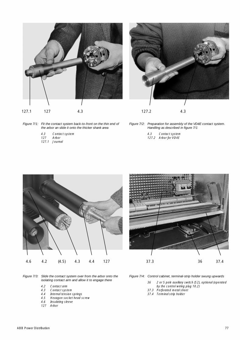
ABB Power Distribution 77
Figure 7/1: Fit the contact system back-to-front on the thin end ofthe arbor an slide it onto the thicker shank area
4.3 Contact system127 Arbor127.1 Journal
Figure 7/2: Preparation for assembly of the VD4E contact system.Handling as described in figure 7/1
4.3 Contact system127.2 Arbor for VD4E
Figure 7/3: Slide the contact system over from the arbor onto theisolating contact arm and allow it to engage there
4.2 Contact arm4.3 Contact system4.4 Internal tension springs4.5 Hexagon socket head screw4.6 Insulating sleeve127 Arbor
Figure 7/4: Control cabinet, terminal-strip holder swung upwards
36 2 or 5 pole auxiliary switch (S2), optional (operatedby the control wiring plug 10.2)
37.3 Perforated metal sheet37.4 Terminal strip holder
127.2 4.34.3127.1 127
127 364.44.3(4.5)4.24.6 37.3 37.4

78 ABB Power Distribution
Figure 7/5: Motorized withdrawable part with circuit-breakertype VD4 in an intermediate position close to thetest/disconnected position, with fitted crank formanual operation and breaker front panel removed
10.3 Control wiring plug connector for withdrawableassembly
13.2.1 ON push rod13.24 Roller13.26 Lever13.92 Angle lever
Figure 7/7: Manually moveable withdrawable part, front panelremoved.
Y0 Blocking magnet
Figure 7/6: Detailed view of the opening and closing mechanism(circuit-breaker type VD4)
13.2.1 ON push rod13.25 Plastic cam13.26 LeverY1 Blocking magnet
13.21
13.26
13.24
10.3
13.92
Y0
Y1
13.2.1
13.26
13.25
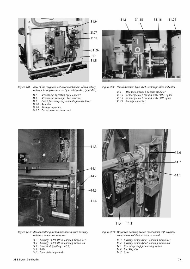
ABB Power Distribution 79
Figure 7/8: View of the magnetic actuator mechanism with auxiliarysystems, front plate removed (circuit-breaker, type VM1)
31.5 Mechanical operating cycle counter31.6 Mechanical switch position indicator31.9 Catch for emergency manual operation lever31.10 Actuator31.26 Storage capacitor31.27 Circuit-breaker control unit
Figure 7/9: Circuit-breaker, type VM1, switch position indicator
31.6 Mechanical switch position indicator31.15 Sensor for VM1 circuit-breaker OFF signal31.16 Sensor for VM1 circuit-breaker ON signal31.26 Storage capacitor
Figure 7/10: Manual earthing switch mechanism with auxiliaryswitches, side cover removed
11.3 Auxiliary switch Q8S1 earthing switch OFF11.4 Auxiliary switch Q8S2 earthing switch ON14.1 Drive shaft (earthing switch)14.2 Slide14.3 Cam plate, adjustable
Figure 7/11: Motorized earthing switch mechanism with auxiliaryswitches as installed, covers removed
11.3 Auxiliary switch Q8S1, earthing switch OFF11.4 Auxiliary switch Q8S2, earthing switch ON14.1 Operating shaft for earthing switch14.6 Blocking disk14.7 Cam
11.3
14.1
14.2
14.3
11.4
14.6
14.7
14.1
11.4 11.3
31.6 31.15 31.16 31.2631.9
31.27
31.10
31.26
31.631.5

80 ABB Power Distribution
Figure 7/12: Detail in the area of a withdrawable part with circuit-breaker type VD4, with travel motor, viewed from theleft-hand side
13.24 Roller13.25 Plastic cam13.26 Lever13.27 Pin13.90 Travel motor13.91 Link rod13.91.1 Bolt13.91.2 Bolt13.92 Angle lever13.92.1 Bolt
Figure 7/14: Mechanical interlock between the withdrawableassembly and the circuit-breaker type VM1, setting ofthe slide blocker.
• Circuit-breaker in closed position
35.5 Pawl in the withdrawable assembly41.1 Link to the actuator41.2 Slide blocker41.3 Screw
13.25
13.26
13.24
13.92
13.91
13.91.2
13.27
13.90
13.91.1
2+1
max
. 0,5
13.92.1
13.25
13.26
13.24
13.92
13.91
13.91.2
13.27
2+1
13.91.1
13.92.1
max
. 0,5
41.3
0,1
+0,
4
41.1
41.2
35.5
Figure 7/13: Mechanical interlock, withdrawable assembly/circuit-breaker, type VD4, with manually operated withdrawablepart
13.24 Roller13.25 Plastic cam13.26 Lever13.27 Pin13.91 Link rod13.91.1 Bolt13.91.2 Bolt13.92 Angle lever13.92.1 Bolt
For further information please refer toinstruction manual BA 433/E
ABB Calor Emag Mittelspannung GmbH ABB Sace T.M.S. S.p.A
Oberhausener Strasse 33 Petzower Strasse 8 Via Friuli, 4D-40472 Ratingen D-14542 Glindow I-24044 Dalmine
Phone: +49(0)21 02/12-12 30, Fax: +49(0)21 02/12-19 16 Phone: +39 035/395111, Fax: +39 035/395874E-Mail: [email protected] E-mail: [email protected]: http://www.abb.de/calor Internet: http://www.abb.com
Inst
ruct
ion
man
ual n
o. G
CE
A 6
8 03
98 P
0102
Prin
ted
in G
erm
any
(06.
00-5
00-P
PI)
W
e re
serv
e th
e rig
ht to
mak
e ch
ange
s in
the
cour
se o
f tec
hnic
al d
evel
opm
ent.