air-insulated substations up to 800 kv · high-voltage substations, such as air-insulat-ed...
TRANSCRIPT
Air-insulated substations up to 800 kV
siemens.com/hv-substations
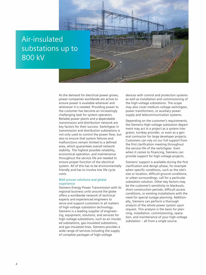
As the demand for electrical power grows, power companies worldwide are active to ensure power is available wherever and whenever it is needed. Providing power to the customer has become an increasingly challenging task for system operators. Reliable power plants and a dependable transmission and distribution network are key factors for their success. Switchgear in transmission and distribution substations is not only used to control the power flow, but also to ensure that system failures and malfunctions remain limited to a defined area, which guarantees overall network stability. The highest possible reliability, economical operation, and maintenance throughout the service life are needed to ensure proper function of the electrical system. All of this has to be environmentally friendly and has to involve low life cycle costs.
Well proven solutions and global experienceSiemens Energy Power Transmission with its regional business units around the globe offers a worldwide network of technical experts and experienced engineers to serve and support customers in all matters of high-voltage substation technology. Siemens is a leading supplier of engineer-ing, equipment, solutions, and services for high-voltage substations, such as air-insulat-ed substations, gas-insulated substations, and gas-insulated lines. Siemens provides a wide range of services including the supply of complete packages of high-voltage
devices with control and protection systems as well as installation and commissioning of the high-voltage substations. The scope may also cover medium-voltage switchgear, power transformers, or auxiliary power supply and telecommunication systems.
Depending on the customer’s requirements, the Siemens High-voltage substation depart-ment may act in a project as a system inte-grator, turnkey provider, or even as a gen-eral contractor for large developer projects. Customers can rely on our full support from the first clarification meeting throughout the service life of the switchgear. Even when it comes to financing, Siemens can provide support for high-voltage projects.
Siemens’ support is available during the first clarification and design phase, for example when specific conditions, such as the site’s size or location, difficult ground conditions, or urban surroundings, call for a particular substation solution. Other key factors may be the customer’s sensitivity to blackouts, short construction periods, difficult access conditions, or existing installations with the need for special outage planning. Addition-ally, Siemens can perform a thorough analysis of the whole power system upon request. This analysis is the basis for plan-ning, installation, commissioning, opera-tion, and maintenance of your high-voltage substation – all from a single source.
Air-insulated substations up to 800 kV
2
Engineered for all environmental conditions
The design of an outdoor substation has to take into account not only the electrical parameters, but also the environmental conditions to which the substation is ex-posed. With Siemens as your partner, you can count on decades of experience in customized outdoor substations and thus leave the responsibility for such projects to us. Based on the customer’s specifications, our planning and design will make sure that the substation fits even the most challeng-ing surroundings. Siemens’ services include selecting suitable high-voltage devices and design for civil works, taking into account proper lightning protection and the required seismic loads. With Siemens responsible for the whole project, you can rest assured that your system will function reliably after commissioning.
Substation configurationMeeting your demands requires the right balance of economy and reliability. Select-ing the best qualified circuit configuration and the appropriate switchgear layout is especially important. Siemens engineers can perform all studies needed for the construc-tion of a high-voltage substation, including earthing, short-circuit, thermal, and me-chanical calculations. Siemens will select the solution that best meets your specifica-tions and system requirements.
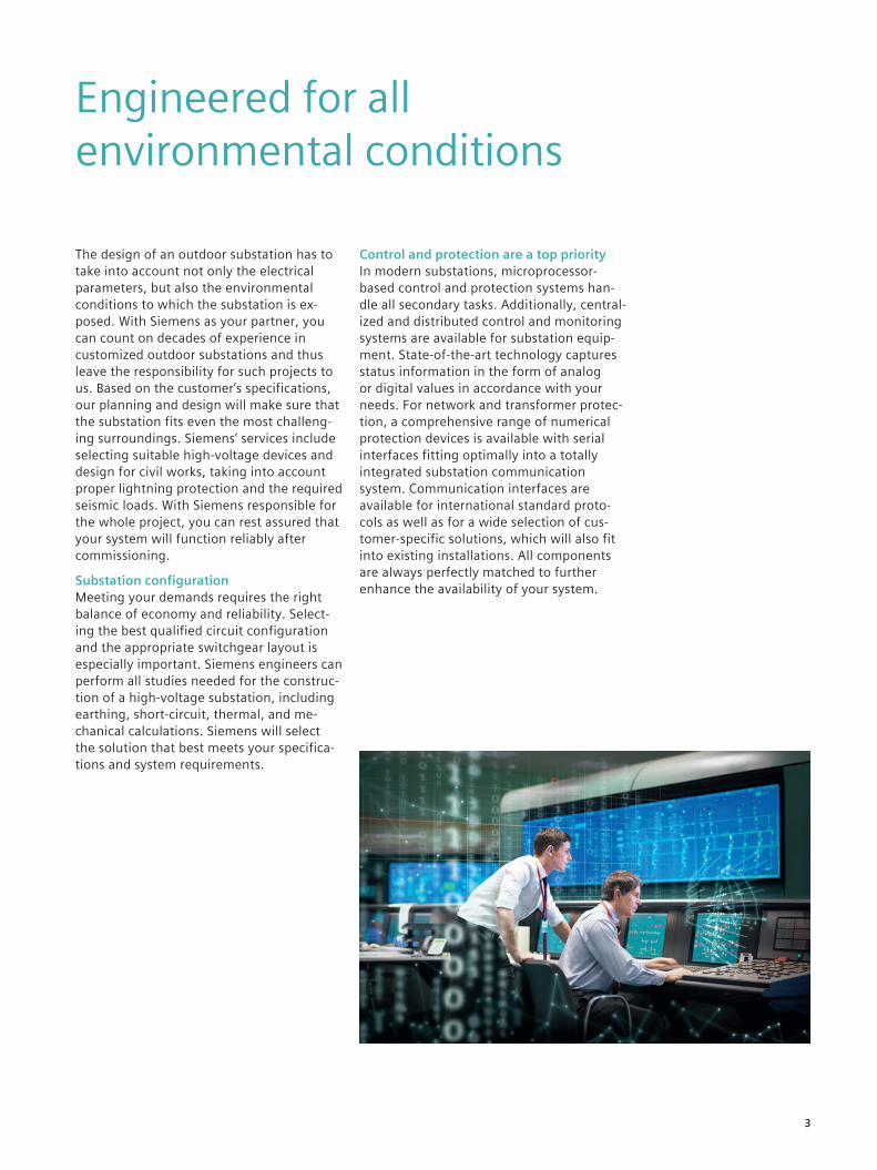
Control and protection are a top priorityIn modern substations, microprocessor-based control and protection systems han-dle all secondary tasks. Additionally, central-ized and distributed control and monitoring systems are available for substation equip-ment. State-of-the-art technology captures status information in the form of analog or digital values in accordance with your needs. For network and transformer protec-tion, a comprehensive range of numerical protection devices is available with serial interfaces fitting optimally into a totally integrated substation communication system. Communication interfaces are available for international standard proto-cols as well as for a wide selection of cus-tomer-specific solutions, which will also fit into existing installations. All components are always perfectly matched to further enhance the availability of your system.
3
Design of air-insulated switchyards
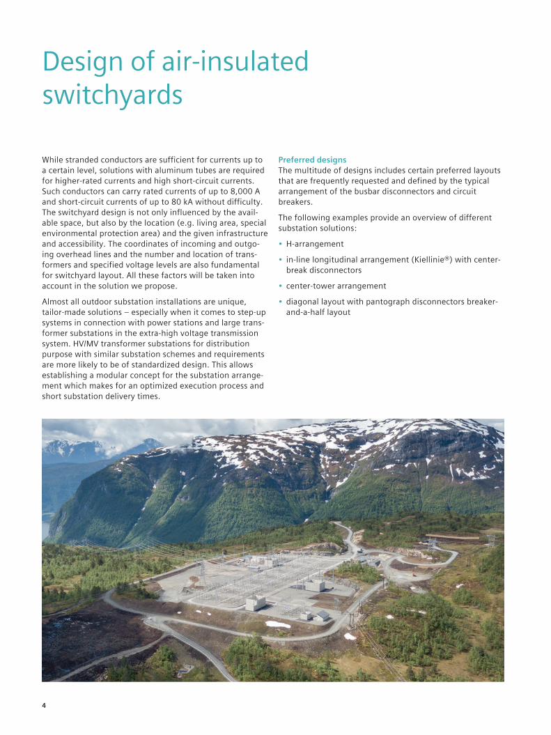
While stranded conductors are sufficient for currents up to a certain level, solutions with aluminum tubes are required for higher-rated currents and high short-circuit currents. Such conductors can carry rated currents of up to 8,000 A and short-circuit currents of up to 80 kA without difficulty. The switchyard design is not only influenced by the avail-able space, but also by the location (e.g. living area, special environmental protection area) and the given infrastructure and accessibility. The coordinates of incoming and outgo-ing overhead lines and the number and location of trans-formers and specified voltage levels are also fundamental for switchyard layout. All these factors will be taken into account in the solution we propose.
Almost all outdoor substation installations are unique, tailor-made solutions – especially when it comes to step-up systems in connection with power stations and large trans-former substations in the extra-high voltage transmission system. HV/MV transformer substations for distribution purpose with similar substation schemes and requirements are more likely to be of standardized design. This allows establishing a modular concept for the substation arrange-ment which makes for an optimized execution process and short substation delivery times.
Preferred designsThe multitude of designs includes certain preferred layouts that are frequently requested and defined by the typical arrangement of the busbar disconnectors and circuit breakers.
The following examples provide an overview of different substation solutions:
• H-arrangement
• in-line longitudinal arrangement (Kiellinie®) with center-break disconnectors
• center-tower arrangement
• diagonal layout with pantograph disconnectors breaker-and-a-half layout
4
H-arrangement
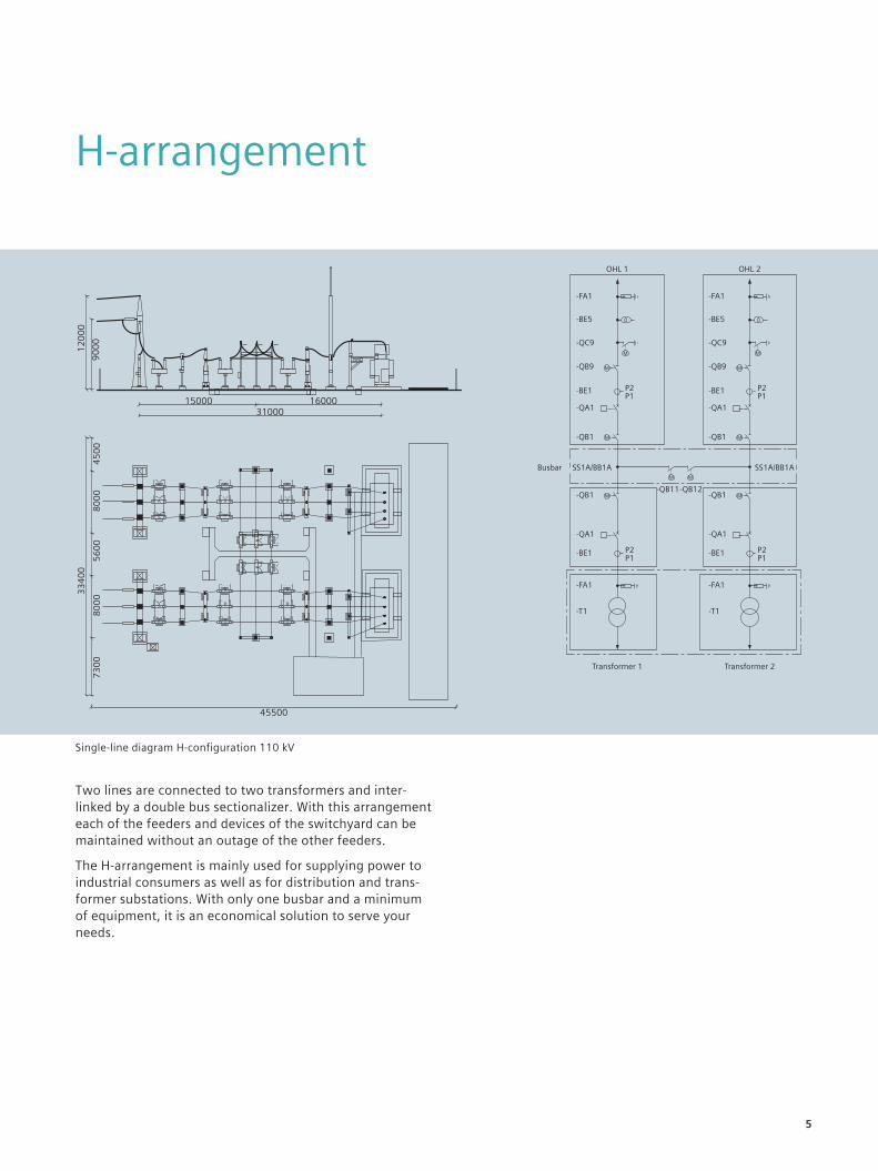
Two lines are connected to two transformers and inter-linked by a double bus sectionalizer. With this arrangement each of the feeders and devices of the switchyard can be maintained without an outage of the other feeders.
The H-arrangement is mainly used for supplying power to industrial consumers as well as for distribution and trans-former substations. With only one busbar and a minimum of equipment, it is an economical solution to serve your needs.
Single-line diagram H-configuration 110 kV
5
In-line longitudinal arrangement
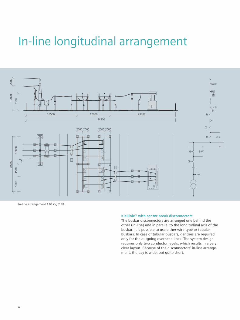
Kiellinie® with center-break disconnectorsThe busbar disconnectors are arranged one behind the other (in-line) and in parallel to the longitudinal axis of the busbar. It is possible to use either wire-type or tubular busbars. In case of tubular busbars, gantries are required only for the outgoing overhead lines. The system design requires only two conductor levels, which results in a very clear layout. Because of the disconnectors’ in-line arrange-ment, the bay is wide, but quite short.
In-line arrangement 110 kV, 2 BB
6
Center-tower arrangement
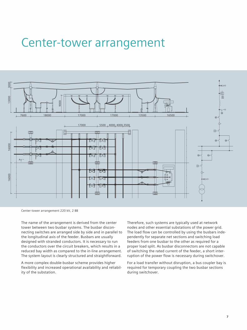
The name of the arrangement is derived from the center tower between two busbar systems. The busbar discon-necting switches are arranged side by side and in parallel to the longitudinal axis of the feeder. Busbars are usually designed with stranded conductors. It is necessary to run the conductors over the circuit breakers, which results in a reduced bay width as compared to the in-line arrangement. The system layout is clearly structured and straightforward.
A more complex double-busbar scheme provides higher flexibility and increased operational availability and reliabil-ity of the substation.
Therefore, such systems are typically used at network nodes and other essential substations of the power grid.The load flow can be controlled by using the busbars inde-pendently for separate net sections and switching load feeders from one busbar to the other as required for a proper load split. As busbar disconnectors are not capable of switching the rated current of the feeder, a short inter-ruption of the power flow is necessary during switchover.
For a load transfer without disruption, a bus coupler bay is required for temporary coupling the two busbar sections during switchover.
Center-tower arrangement 220 kV, 2 BB
7
Diagonal layout with pantograph disconnectors
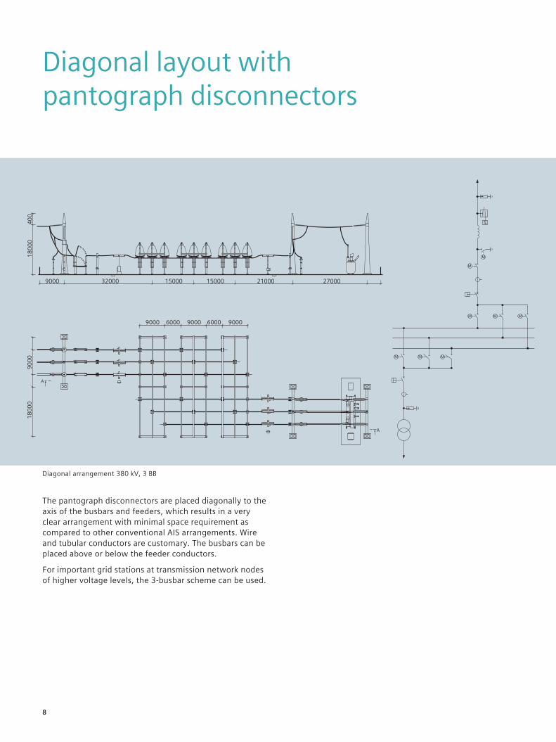
The pantograph disconnectors are placed diagonally to the axis of the busbars and feeders, which results in a very clear arrangement with minimal space requirement as compared to other conventional AIS arrangements. Wire and tubular conductors are customary. The busbars can be placed above or below the feeder conductors.
For important grid stations at transmission network nodes of higher voltage levels, the 3-busbar scheme can be used.
Diagonal arrangement 380 kV, 3 BB
8
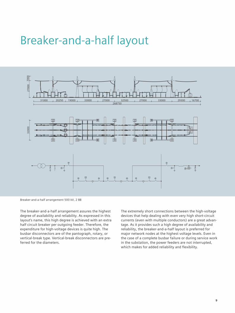
Breaker-and-a-half layout
The breaker-and-a-half arrangement assures the highest degree of availability and reliability. As expressed in this layout’s name, this high degree is achieved with an extra half circuit breaker per outgoing feeder. Therefore, the expenditure for high-voltage devices is quite high. The busbar disconnectors are of the pantograph, rotary, or vertical-break type. Vertical-break disconnectors are pre-ferred for the diameters.
The extremely short connections between the high-voltage devices that help dealing with even very high short-circuit currents (even with multiple conductors) are a great advan-tage. As it provides such a high degree of availability and reliability, the breaker-and-a-half layout is preferred for major network nodes at the highest voltage levels. Even in the case of a complete busbar failure or during service work in the substation, the power feeders are not interrupted, which makes for added reliability and flexibility.
Breaker-and-a-half arrangement 500 kV, 2 BB
9
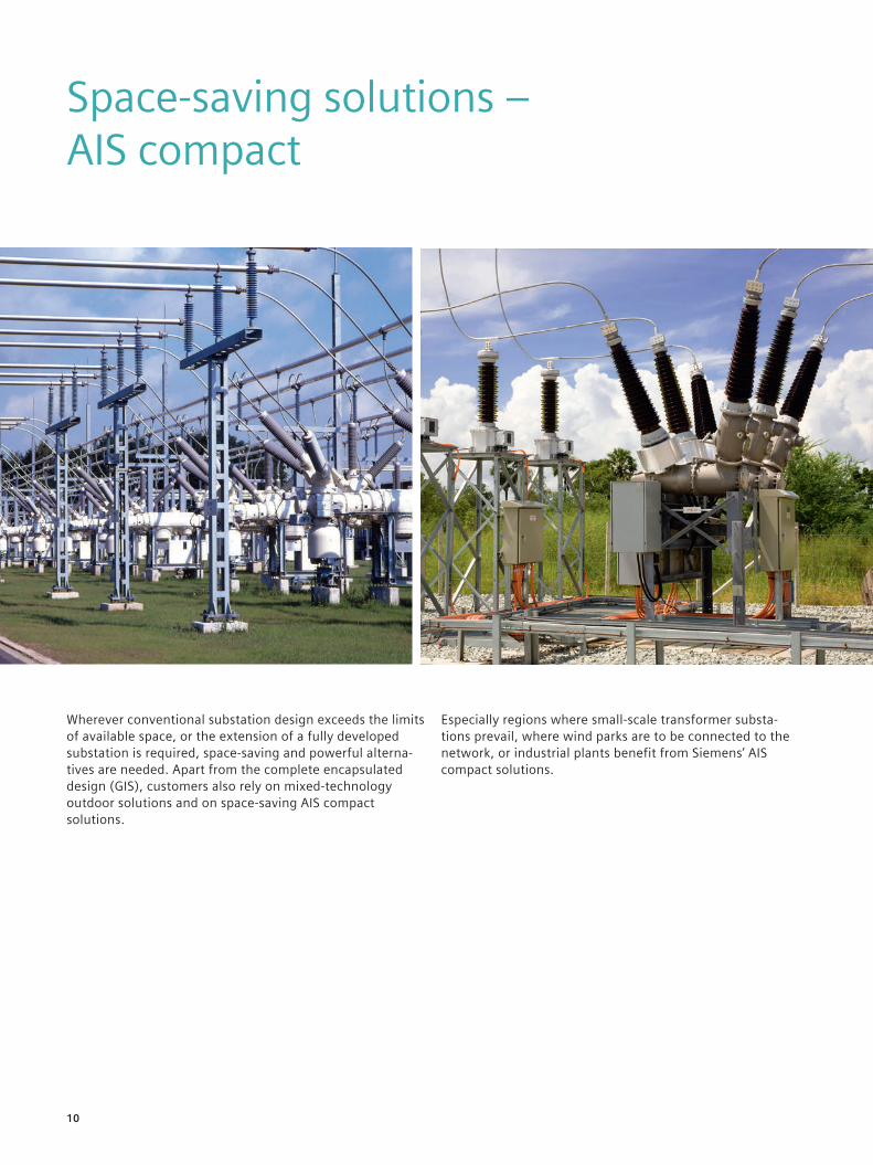
Wherever conventional substation design exceeds the limits of available space, or the extension of a fully developed substation is required, space-saving and powerful alterna-tives are needed. Apart from the complete encapsulated design (GIS), customers also rely on mixed-technology outdoor solutions and on space-saving AIS compact solutions.
Especially regions where small-scale transformer substa-tions prevail, where wind parks are to be connected to the network, or industrial plants benefit from Siemens’ AIS compact solutions.
Space-saving solutions – AIS compact
10
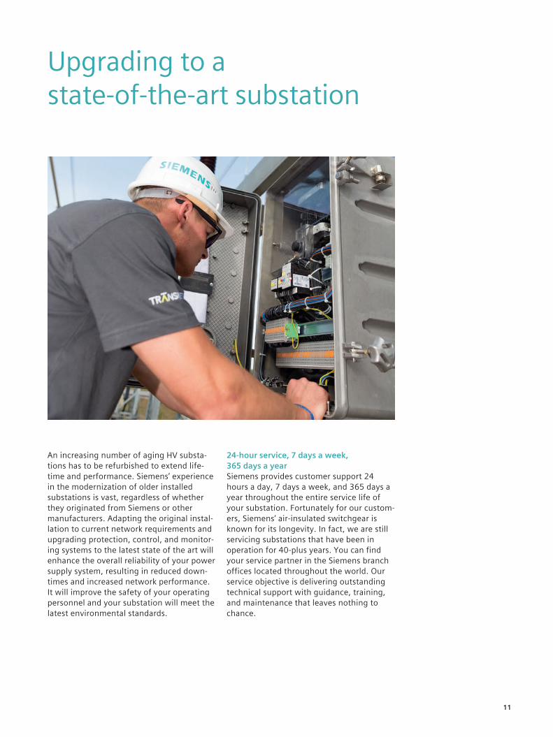
Upgrading to a state-of-the-art substation
An increasing number of aging HV substa-tions has to be refurbished to extend life-time and performance. Siemens’ experience in the modernization of older installed substations is vast, regardless of whether they originated from Siemens or other manufacturers. Adapting the original instal-lation to current network requirements and upgrading protection, control, and monitor-ing systems to the latest state of the art will enhance the overall reliability of your power supply system, resulting in reduced down-times and increased network performance. It will improve the safety of your operating personnel and your substation will meet the latest environmental standards.
24-hour service, 7 days a week, 365 days a yearSiemens provides customer support 24 hours a day, 7 days a week, and 365 days a year throughout the entire service life of your substation. Fortunately for our custom-ers, Siemens’ air-insulated switchgear is known for its longevity. In fact, we are still servicing substations that have been in operation for 40-plus years. You can find your service partner in the Siemens branch offices located throughout the world. Our service objective is delivering outstanding technical support with guidance, training, and maintenance that leaves nothing to chance.
11
Published by and copyright © 2017: Siemens AG Energy Management Division Freyeslebenstrasse 1 91058 Erlangen, Germany
For more information, please contact our Customer Support Center. Phone: +49 180 524 70 00 Fax: +49 180 524 24 71 (Charges depending on provider) E-mail: [email protected]
Article No. EMTS-B10029-00-7600 Dispo 30003 fb 7356 WS 0917
Subject to changes and errors.
The information given in this document only con-tains general descriptions and/or performance features which may not always specifically reflect those described, or which may undergo modifica-tion in the course of further development of the products. The requested performance features are binding only when they are expressly agreed upon in the concluded contract.