air to water heat pump service manual · air to water heat pump hydro unit hws-p805xwhm3-e(tr)...
TRANSCRIPT

Model name:
Outdoor unit
HWS-P805HR-E(TR)HWS-P1105HR-E(TR)
AIR TO WATER HEAT PUMP
Hydro unit
HWS-P805XWHM3-E(TR)HWS-P805XWHT6-E(TR)HWS-P805XWHT9-EHWS-P1105XWHM3-E(TR)HWS-P1105XWHT6-E(TR)HWS-P1105XWHT9-E(TR)
Service Manual
FILE No. A10-1705
Contents
1 Safety precautions. . . . . . . . . . . . . . . . . . . . . . . . . . . . . . . . . . . . . . . . . . . . . . . . . . . . . 3
2 Refrigerant (R410A) . . . . . . . . . . . . . . . . . . . . . . . . . . . . . . . . . . . . . . . . . . . . . . . . . . . . 6
2-1.Safety during installation and service . . . . . . . . . . . . . . . . . . . . . . . . . . . . . . . . . . . . . . . . . . . . . . . . 6
2-2.Installing refrigerant pipe . . . . . . . . . . . . . . . . . . . . . . . . . . . . . . . . . . . . . . . . . . . . . . . . . . . . . . . . . 7
2-2-1.Steel pipe and joint . . . . . . . . . . . . . . . . . . . . . . . . . . . . . . . . . . . . . . . . . . . . . . . . . . . . . . . 7
2-2-2.Processing of piping materials . . . . . . . . . . . . . . . . . . . . . . . . . . . . . . . . . . . . . . . . . . . . . . 8
2-3.Tools. . . . . . . . . . . . . . . . . . . . . . . . . . . . . . . . . . . . . . . . . . . . . . . . . . . . . . . . . . . . . . . . . . . . . . . . 10
2-3-1.Necessary tools. . . . . . . . . . . . . . . . . . . . . . . . . . . . . . . . . . . . . . . . . . . . . . . . . . . . . . . . . 10
2-4.Recharging of refrigerant . . . . . . . . . . . . . . . . . . . . . . . . . . . . . . . . . . . . . . . . . . . . . . . . . . . . . . . . 11
2-5.Brazing of pipes . . . . . . . . . . . . . . . . . . . . . . . . . . . . . . . . . . . . . . . . . . . . . . . . . . . . . . . . . . . . . . . 13
2-5-1.Materials of brazing. . . . . . . . . . . . . . . . . . . . . . . . . . . . . . . . . . . . . . . . . . . . . . . . . . . . . . 13
2-5-2.Flux . . . . . . . . . . . . . . . . . . . . . . . . . . . . . . . . . . . . . . . . . . . . . . . . . . . . . . . . . . . . . . . . . . 13
2-5-3.Brazing . . . . . . . . . . . . . . . . . . . . . . . . . . . . . . . . . . . . . . . . . . . . . . . . . . . . . . . . . . . . . . . 13
3 Specifications . . . . . . . . . . . . . . . . . . . . . . . . . . . . . . . . . . . . . . . . . . . . . . . . . . . . . . . 15
4 Outside drawing. . . . . . . . . . . . . . . . . . . . . . . . . . . . . . . . . . . . . . . . . . . . . . . . . . . . . . 17
4-1.Hydro unit . . . . . . . . . . . . . . . . . . . . . . . . . . . . . . . . . . . . . . . . . . . . . . . . . . . . . . . . . . . . . . . . . . . . 17
4-2.Outdoor unit . . . . . . . . . . . . . . . . . . . . . . . . . . . . . . . . . . . . . . . . . . . . . . . . . . . . . . . . . . . . . . . . . . 18
4-3.Hot water cylinder . . . . . . . . . . . . . . . . . . . . . . . . . . . . . . . . . . . . . . . . . . . . . . . . . . . . . . . . . . . . . . 19
5 Wiring diagram. . . . . . . . . . . . . . . . . . . . . . . . . . . . . . . . . . . . . . . . . . . . . . . . . . . . . . . 20
5-1.Hydro unit . . . . . . . . . . . . . . . . . . . . . . . . . . . . . . . . . . . . . . . . . . . . . . . . . . . . . . . . . . . . . . . . . . . . 20
5-2.Outdoor unit . . . . . . . . . . . . . . . . . . . . . . . . . . . . . . . . . . . . . . . . . . . . . . . . . . . . . . . . . . . . . . . . . . 21
5-3.Hot water cylinder unit . . . . . . . . . . . . . . . . . . . . . . . . . . . . . . . . . . . . . . . . . . . . . . . . . . . . . . . . . . 22
6 Key electric component rating . . . . . . . . . . . . . . . . . . . . . . . . . . . . . . . . . . . . . . . . . . 23
6-1.Hydro unit . . . . . . . . . . . . . . . . . . . . . . . . . . . . . . . . . . . . . . . . . . . . . . . . . . . . . . . . . . . . . . . . . . . . 23
6-2.Outdoor unit . . . . . . . . . . . . . . . . . . . . . . . . . . . . . . . . . . . . . . . . . . . . . . . . . . . . . . . . . . . . . . . . . . 25
6-3.Hot water cylinder unit . . . . . . . . . . . . . . . . . . . . . . . . . . . . . . . . . . . . . . . . . . . . . . . . . . . . . . . . . . 25
6-4.Water heat exchange control board . . . . . . . . . . . . . . . . . . . . . . . . . . . . . . . . . . . . . . . . . . . . . . . . 26
6-5.Outdoor control board. . . . . . . . . . . . . . . . . . . . . . . . . . . . . . . . . . . . . . . . . . . . . . . . . . . . . . . . . . . 27
7 Refrigeration cycle / Water system diagram. . . . . . . . . . . . . . . . . . . . . . . . . . . . . . . 28
7-1.Water system diagram . . . . . . . . . . . . . . . . . . . . . . . . . . . . . . . . . . . . . . . . . . . . . . . . . . . . . . . . . . 28
7-2.Refrigeration cycle system diagram . . . . . . . . . . . . . . . . . . . . . . . . . . . . . . . . . . . . . . . . . . . . . . . . 30
8 Operational description . . . . . . . . . . . . . . . . . . . . . . . . . . . . . . . . . . . . . . . . . . . . . . . 31
1

9 Method of defect diagnosis . . . . . . . . . . . . . . . . . . . . . . . . . . . . . . . . . . . . . . . . . . . . 71
9-1.Matters to be confirmed first . . . . . . . . . . . . . . . . . . . . . . . . . . . . . . . . . . . . . . . . . . . . . . . . . . . . . . 72
9-1-1.Check the power supply voltage . . . . . . . . . . . . . . . . . . . . . . . . . . . . . . . . . . . . . . . . . . . . 72
9-1-2.Check for any miswiring of the connection cables between the hydro unit and the outdoor unit
. . . . . . . . . . . . . . . . . . . . . . . . . . . . . . . . . . . . 72
9-1-3.About the installation of the temperature sensor. . . . . . . . . . . . . . . . . . . . . . . . . . . . . . . . 72
9-2.Non-defective operation (program operation) … No fault code display appears.. . . . . . . . . . . . . . 72
9-3.Outline of the determination diagram . . . . . . . . . . . . . . . . . . . . . . . . . . . . . . . . . . . . . . . . . . . . . . . 73
9-3-1.Procedure of defect diagnosis. . . . . . . . . . . . . . . . . . . . . . . . . . . . . . . . . . . . . . . . . . . . . . 73
9-3-2.How to determine from the check code on the remote controller . . . . . . . . . . . . . . . . . . . 73
9-3-3.How to cancel a check code on the remote controller . . . . . . . . . . . . . . . . . . . . . . . . . . . 73
9-3-4.How to diagnose by error code . . . . . . . . . . . . . . . . . . . . . . . . . . . . . . . . . . . . . . . . . . . . . 74
9-4.Diagnosis flow chart for each error code . . . . . . . . . . . . . . . . . . . . . . . . . . . . . . . . . . . . . . . . . . . . 82
9-4-1.Hydro unit failure detection . . . . . . . . . . . . . . . . . . . . . . . . . . . . . . . . . . . . . . . . . . . . . . . . 82
9-4-2.Outdoor unit failure detection . . . . . . . . . . . . . . . . . . . . . . . . . . . . . . . . . . . . . . . . . . . . . 101
9-4-3.Temperature sensor, temperature-resistance characteristic table . . . . . . . . . . . . . . . . . 113
9-5.Operation check by PC board switch . . . . . . . . . . . . . . . . . . . . . . . . . . . . . . . . . . . . . . . . . . . . . . 114
9-5-1.Operation check mode . . . . . . . . . . . . . . . . . . . . . . . . . . . . . . . . . . . . . . . . . . . . . . . . . . 114
9-6.Brief method for checking the key components . . . . . . . . . . . . . . . . . . . . . . . . . . . . . . . . . . . . . . 115
9-6-1.Hydro unit . . . . . . . . . . . . . . . . . . . . . . . . . . . . . . . . . . . . . . . . . . . . . . . . . . . . . . . . . . . . 115
9-6-2.Outdoor unit . . . . . . . . . . . . . . . . . . . . . . . . . . . . . . . . . . . . . . . . . . . . . . . . . . . . . . . . . . 116
10 Hydro unit and outdoor unit settings . . . . . . . . . . . . . . . . . . . . . . . . . . . . . . . . . . . 117
11 Replacement of the service PC board . . . . . . . . . . . . . . . . . . . . . . . . . . . . . . . . . . . 154
12 How to exchange main parts . . . . . . . . . . . . . . . . . . . . . . . . . . . . . . . . . . . . . . . . . . 155
13 For cooling installation . . . . . . . . . . . . . . . . . . . . . . . . . . . . . . . . . . . . . . . . . . . . . . . 173
14 Periodic inspection items . . . . . . . . . . . . . . . . . . . . . . . . . . . . . . . . . . . . . . . . . . . . . 174
15 Part exploded view, part list . . . . . . . . . . . . . . . . . . . . . . . . . . . . . . . . . . . . . . . . . . . 175
2

1 Safety precautionsThe unit and this service guide list very important safety precautions.Understand the following details (indications and symbols) before reading the body text, and follow the instructions.
[About indication]
* Property damage indicates extended damage to property, furniture, livestock, or pets.
[About symbols]
Indication Meaning of Indication
DANGER Indicates that a wrong operation may cause a service engineer and the third persons around to get fatal or serious injuries.
WARNINGIndicates that a wrong operation may cause a service engineer and the third persons around to get fatal or serious injuries, or that unit defective after the operation may cause a user to have a similar serious accident.
CAUTIONIndicates that a wrong operation may cause a service engineer and the third persons around to get injuries or may cause property damage*, or that unit defective after the operation may cause a user to have a similar accident.
Symbols Meaning of Symbols
Indicates a forbidden action.
Specific forbidden actions are described in text near the symbol.
Indicates a forcible (must do) action.
Specific forcible actions are described in text near the symbol.
Indicates a caution (including danger and warning).
Specific cautions are described in picture or text inside or near the symbol.
DANGER
<Turn off the power breaker>
Turn off the power breaker before removing the front panel and cabinet.• Failure to do so may cause a high voltage electric shock, leading to death or injury.• During an operation, the second side circuit of high pressure transmission(*) are applied with a high voltage of 230 V
or higher.• Touching the circuit even with an electrical insulator, let alone a bare hand or body, causes an electric shock.
∗: For details, see the schematic.
<Discharge between terminals>
When the front panel and cabinet are removed, make short-circuit current to discharge between high pressure capacitor terminals.
• Failure to do so may cause a high voltage electric shock, leading to death or injury.• After the power is turned off, the high pressure capacitor is still charged with high voltage.
<Forbidden>
Do not turn on the power breaker after removing the front panel cabinet.• Failure to do so may cause a high voltage electric shock, leading to death or injury.
WARNING
<Check earth ground>
Before starting failure diagnosis or repair, check that the earth wire (∗) is connected to the unit ground terminal.• An unconnected earth wire could cause an electric shock if electric leakage occurs.• If the earth ground is not properly connected, ask an electrical worker for rework of the ground connection.
∗: Earth wire of class D grounding
3

<No modification>
Do not modify the unit.• Do not disassemble or modify the parts also.• A fire, an electric shock, or an injury may occur.
<Use specified parts>
Use the specified parts (∗) when replacing them.• Using parts other than specified ones may cause a fire or an electric shock.
∗: For details, see the parts price list.
<Keep children away from unit>
Keep any person (including children) other than service engineers away from a failure diagnosis or repairing place. • A tool or disassembled parts may cause an injury.• Advise the customer to keep the third persons (including children) away from the unit.
<Insulation treatment>
After connecting a cut lead with a crimp contact, discharge by facing the closed side upward.• Connect lead wires with crimping terminals and turn the closed end upwards to avoid exposure to water.
<Watch out for fire>
Observe the following instructions when repairing the refrigerant cycle.(1) Watch out for surrounding fire. Always put out the fire of stove burner or other devices before starting the repair.
Should the fire fail to be put out, the oil mixed with refrigerant gas could catch fire.(2) Do no use a welder in a closed room.
A room with no ventilation may cause carbon monoxide poisoning.(3) Keep away flammable materials.
The materials may catch the fire of a welder.
<Use refrigerant carefully>
Check the refrigerant name to use the tools and members appropriate for the refrigerant.• A product using the refrigerant R410A has the refrigerant name prominently displayed on its outdoor unit. In
addition, the diameter of the service port is changed from that of the conventional R22 to prevent incorrect filling.
Never use refrigerant other than R410A for Air to Water Heat Pump using R410A. Also, never use R410A for Air to Water Heat Pump using other refrigerant (such as R22).
• A mixture of R410A with different ones excessively raises the pressure in the refrigerant cycle, leading to an injury due to burst.
Do not make additional charge of the refrigerant.• An additional charge when refrigerant gas leaks changes the refrigerant composition in the refrigerant cycle,
causing the characteristics change of the Air to Water Heat Pump or excessive high pressure in the refrigerant cycle with more than the specified amount of refrigerant charged. This may cause burst or an injury. If the refrigerant gas leaks, perform refrigerant recovery or other operation to make the Air to Water Heat Pump contain no refrigerant, and then perform vacuuming. After that, refill the unit with the defined amount of liquid refrigerant. Never charge refrigerant exceeding the amount specified.
When the refrigerant cycle is refilled with refrigerant, do not enter air or refrigerants other than the specified refrigerant, R410A.
• A mixture of R410A with air or an inappropriate substance causes excessive high pressure inside the refrigerant cycle, leading to an injury due to burst.
Check that there is no refrigerant gas leak after the installation is completed.• If it catches fire of a fan heater, a space heater, or a stove, poisonous gases may be produced.
<Be careful with wiring>
After a repair is completed, be sure to reassemble the parts and put the wiring back to its original state. In addition, be careful with the internal wiring not to be caught in a cabinet or panel.
• A defective assembly or wiring may cause a disaster at a customer site due to electrical leakage or a fire.
<Check for water leak>
After the repair of a water pathway is completed, check that there is no water leak.• In using the product, water leak may cause a fire at a customer site due to electrical leakage or an electric shock.
WARNING
4
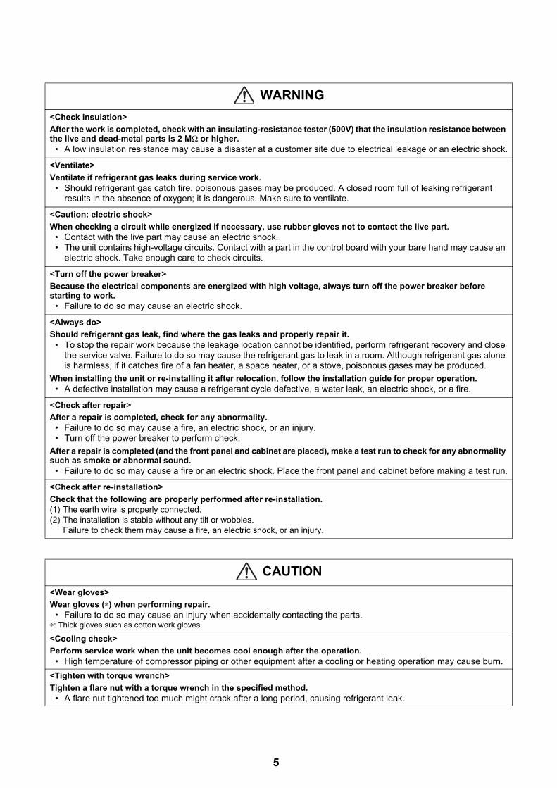
<Check insulation>
After the work is completed, check with an insulating-resistance tester (500V) that the insulation resistance between the live and dead-metal parts is 2 MΩ or higher.
• A low insulation resistance may cause a disaster at a customer site due to electrical leakage or an electric shock.
<Ventilate>
Ventilate if refrigerant gas leaks during service work.• Should refrigerant gas catch fire, poisonous gases may be produced. A closed room full of leaking refrigerant
results in the absence of oxygen; it is dangerous. Make sure to ventilate.
<Caution: electric shock>
When checking a circuit while energized if necessary, use rubber gloves not to contact the live part.• Contact with the live part may cause an electric shock.• The unit contains high-voltage circuits. Contact with a part in the control board with your bare hand may cause an
electric shock. Take enough care to check circuits.
<Turn off the power breaker>
Because the electrical components are energized with high voltage, always turn off the power breaker before starting to work.
• Failure to do so may cause an electric shock.
<Always do>
Should refrigerant gas leak, find where the gas leaks and properly repair it.• To stop the repair work because the leakage location cannot be identified, perform refrigerant recovery and close
the service valve. Failure to do so may cause the refrigerant gas to leak in a room. Although refrigerant gas alone is harmless, if it catches fire of a fan heater, a space heater, or a stove, poisonous gases may be produced.
When installing the unit or re-installing it after relocation, follow the installation guide for proper operation.• A defective installation may cause a refrigerant cycle defective, a water leak, an electric shock, or a fire.
<Check after repair>
After a repair is completed, check for any abnormality.• Failure to do so may cause a fire, an electric shock, or an injury.• Turn off the power breaker to perform check.
After a repair is completed (and the front panel and cabinet are placed), make a test run to check for any abnormality such as smoke or abnormal sound.
• Failure to do so may cause a fire or an electric shock. Place the front panel and cabinet before making a test run.
<Check after re-installation>
Check that the following are properly performed after re-installation.(1) The earth wire is properly connected.(2) The installation is stable without any tilt or wobbles.
Failure to check them may cause a fire, an electric shock, or an injury.
CAUTION
<Wear gloves>
Wear gloves (∗) when performing repair.• Failure to do so may cause an injury when accidentally contacting the parts.
∗: Thick gloves such as cotton work gloves
<Cooling check>
Perform service work when the unit becomes cool enough after the operation.• High temperature of compressor piping or other equipment after a cooling or heating operation may cause burn.
<Tighten with torque wrench>
Tighten a flare nut with a torque wrench in the specified method.• A flare nut tightened too much might crack after a long period, causing refrigerant leak.
WARNING
5

2 Refrigerant (R410A) This Air to Water Heat Pump adopts a refrigerant HFC (R410A) to prevent destruction of the ozone layer.The working pressure of R410A refrigerant is 1.6 times higher than that of the conventional refrigerant R22.The refrigerant oil is also changed for the new refrigeration. Therefore, during installation or service work, be sure that water, dust, former refrigerant, or refrigeration machine oil does not enter the refrigerant cycle of the new type refrigerant Air to Water Heat Pump. A wrong installation or service operation may cause a serious accident.Read carefully the following instructions to use the tools or members for R410A for safety work.
2-1. Safety during installation and service• Use only the refrigerant R410A for Air to Water Heat Pump using R410A.
A mixture of R410A with different ones excessively raises the pressure in a refrigerant cycle, leading to an injury due to burst.
• Check the refrigerant name to use the tools and members appropriate for the refrigerant.A product using the refrigerant R410A has the refrigerant name prominently displayed on its outdoor unit. In addition, the diameter of the service port is changed from that of the conventional R22 to prevent incorrect filling.
• Ventilate if refrigerant gas leaks during service work.Should refrigerant gas catch fire, poisonous gases may be produced. A closed room full of leaking refrigerant results in the absence of oxygen; it is dangerous. Make sure to ventilate.
• When the refrigerant cycle is refilled with refrigerant, do not mix air or refrigerants other than the specified refrigerant, R410A.A mixture of R410A with air or an inappropriate substance causes excessive high pressure inside the refrigerant cycle, leading to an injury due to burst.
• Check that no refrigerant gas leaks after the installation is completed.Should a refrigerant gas leak in a room and catch fire, poisonous gases may be produced.
• When installing the unit that contains large amount of refrigerant such as Air to Water Heat Pump, take measures to prevent the refrigerant from exceeding the threshold concentration in case it leaks.Should leaking refrigerant exceed the threshold concentration could cause an accident due to oxygen deficient.
• When installing the unit or re-installing it after relocation, follow the installation guide for proper operation.A defective installation may cause a refrigerant cycle defective, a water leak, an electric shock, or a fire.
• Do not modify the product. Do not disassemble or modify the parts also.A fire, an electric shock, or an injury may occur.
6
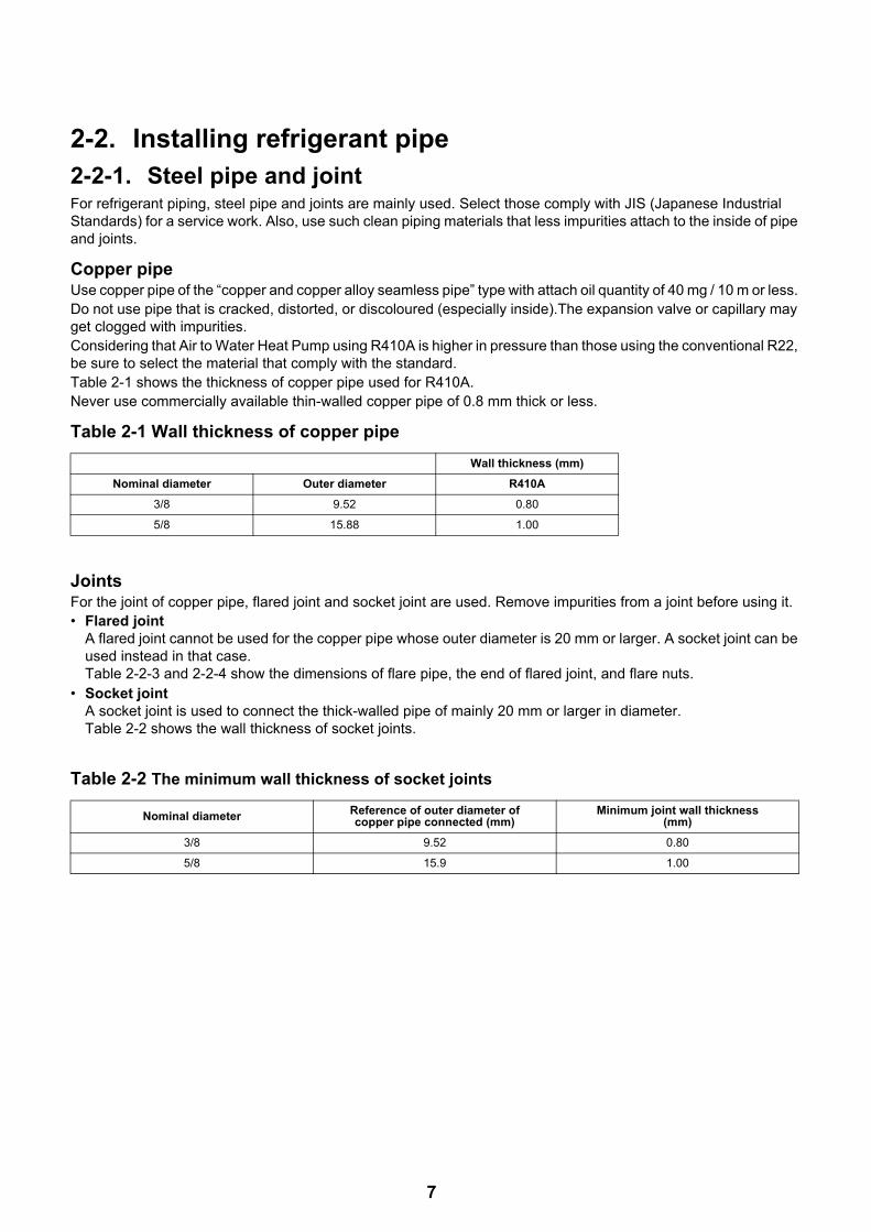
2-2. Installing refrigerant pipe2-2-1. Steel pipe and jointFor refrigerant piping, steel pipe and joints are mainly used. Select those comply with JIS (Japanese Industrial Standards) for a service work. Also, use such clean piping materials that less impurities attach to the inside of pipe and joints.
Copper pipeUse copper pipe of the “copper and copper alloy seamless pipe” type with attach oil quantity of 40 mg / 10 m or less. Do not use pipe that is cracked, distorted, or discoloured (especially inside).The expansion valve or capillary may get clogged with impurities.Considering that Air to Water Heat Pump using R410A is higher in pressure than those using the conventional R22, be sure to select the material that comply with the standard.Table 2-1 shows the thickness of copper pipe used for R410A.Never use commercially available thin-walled copper pipe of 0.8 mm thick or less.
Table 2-1 Wall thickness of copper pipe
JointsFor the joint of copper pipe, flared joint and socket joint are used. Remove impurities from a joint before using it.• Flared joint
A flared joint cannot be used for the copper pipe whose outer diameter is 20 mm or larger. A socket joint can be used instead in that case.Table 2-2-3 and 2-2-4 show the dimensions of flare pipe, the end of flared joint, and flare nuts.
• Socket jointA socket joint is used to connect the thick-walled pipe of mainly 20 mm or larger in diameter.Table 2-2 shows the wall thickness of socket joints.
Table 2-2 The minimum wall thickness of socket joints
Wall thickness (mm)
Nominal diameter Outer diameter R410A
3/8 9.52 0.80
5/8 15.88 1.00
Nominal diameter Reference of outer diameter of copper pipe connected (mm)
Minimum joint wall thickness (mm)
3/8 9.52 0.80
5/8 15.9 1.00
7
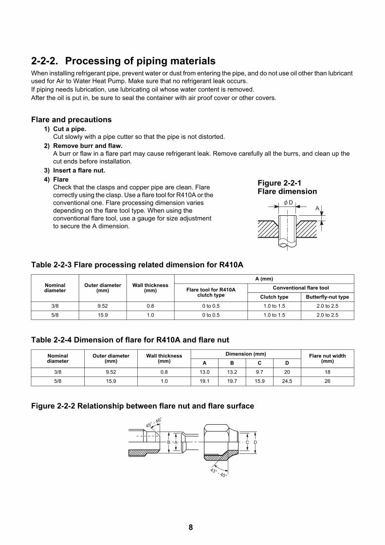
2-2-2. Processing of piping materialsWhen installing refrigerant pipe, prevent water or dust from entering the pipe, and do not use oil other than lubricant used for Air to Water Heat Pump. Make sure that no refrigerant leak occurs.If piping needs lubrication, use lubricating oil whose water content is removed.After the oil is put in, be sure to seal the container with air proof cover or other covers.
Flare and precautions1) Cut a pipe.
Cut slowly with a pipe cutter so that the pipe is not distorted.
2) Remove burr and flaw.A burr or flaw in a flare part may cause refrigerant leak. Remove carefully all the burrs, and clean up the cut ends before installation.
3) Insert a flare nut.
4) FlareCheck that the clasps and copper pipe are clean. Flare correctly using the clasp. Use a flare tool for R410A or the conventional one. Flare processing dimension varies depending on the flare tool type. When using the conventional flare tool, use a gauge for size adjustment to secure the A dimension.
Table 2-2-3 Flare processing related dimension for R410A
Table 2-2-4 Dimension of flare for R410A and flare nut
Figure 2-2-2 Relationship between flare nut and flare surface
Nominal diameter
Outer diameter (mm)
Wall thickness (mm)
A (mm)
Flare tool for R410A clutch type
Conventional flare tool
Clutch type Butterfly-nut type
3/8 9.52 0.8 0 to 0.5 1.0 to 1.5 2.0 to 2.5
5/8 15.9 1.0 0 to 0.5 1.0 to 1.5 2.0 to 2.5
Nominal diameter
Outer diameter (mm)
Wall thickness (mm)
Dimension (mm) Flare nut width (mm)A B C D
3/8 9.52 0.8 13.0 13.2 9.7 20 18
5/8 15.9 1.0 19.1 19.7 15.9 24.5 26
AD
Figure 2-2-1 Flare dimension
DCB A
45° - 46°
43° - 45°
8
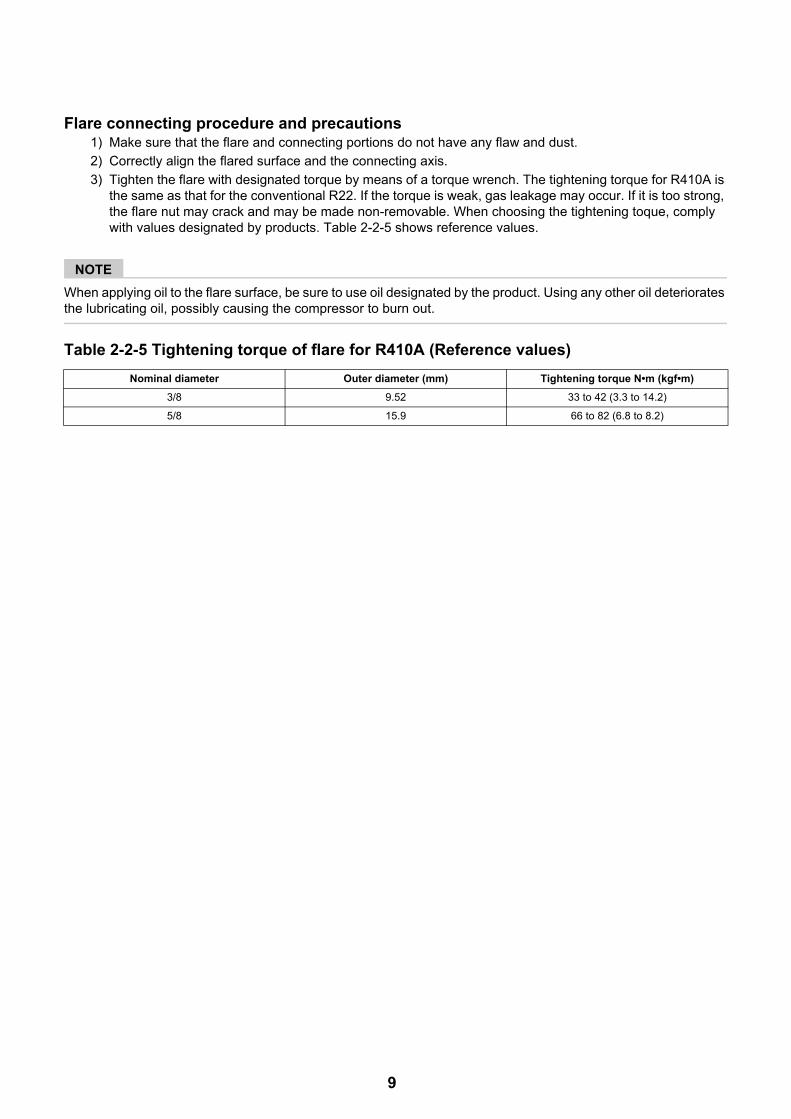
Flare connecting procedure and precautions1) Make sure that the flare and connecting portions do not have any flaw and dust.
2) Correctly align the flared surface and the connecting axis.
3) Tighten the flare with designated torque by means of a torque wrench. The tightening torque for R410A is the same as that for the conventional R22. If the torque is weak, gas leakage may occur. If it is too strong, the flare nut may crack and may be made non-removable. When choosing the tightening toque, comply with values designated by products. Table 2-2-5 shows reference values.
NOTE
When applying oil to the flare surface, be sure to use oil designated by the product. Using any other oil deteriorates the lubricating oil, possibly causing the compressor to burn out.
Table 2-2-5 Tightening torque of flare for R410A (Reference values)
Nominal diameter Outer diameter (mm) Tightening torque N•m (kgf•m)
3/8 9.52 33 to 42 (3.3 to 14.2)
5/8 15.9 66 to 82 (6.8 to 8.2)
9

2-3. Tools2-3-1. Necessary toolsIn Air to Water Heat Pump using R410A, the service port diameter of packed valve of the outdoor unit is changed to prevent mixing of other refrigerant. To reinforce the pressure resistance, flare dimensions and opposite side dimensions of flare nut (For Ø 12.7 copper pipe) of the refrigerant piping are lengthened.Because the refrigerating machine oil is changed, mixing of oil may generate sludge, clog capillary, or cause other problems. Accordingly, the tools to be used include:• tools dedicated for R410A (Those that cannot be used for the conventional refrigerant, R22)• tools dedicated for R410A, but can be also used for the conventional refrigerant, R22• tools that can be used for the conventional refrigerant, R22.
The following table shows the tools dedicated for R410A and their interchangeability.
Tools dedicated for R410A (The following tools must be for R410A)Tools whose specifications are changed for R410A and their interchangeability
* (Note 1) Flaring for R410A by using the conventional flare tool requires projection margin adjustment. This adjustment requires copper pipe gauge or other instrument.
* (Note 2) A charging cylinder for R410A is currently under development.
General tools (Conventional tools are available)In addition to the above dedicated tools, the following equipment also available for R22 is necessary as the general tools.
Also prepare the following equipment for other work methods or run check.
No. Tool to be used Usage
R410A Air to Water Hear Pump installation
Conventional refrigerant Air to Water Heat Pump
installation
For R410A Existence of new
equipment
Conventional equipment can be
used
New equipment can be used with conventional
refrigerant
1 Flare tool Pipe flaring Yes *(Note 1) Yes
2 Copper pipe gauge for adjusting projection margin
Flaring by conventional flare tool Yes *(Note 1) *(Note 1)
3 Torque wrench (For Ø15.9) Connection of flare nut Yes No No
4 Gauge manifold Evacuating, refrigerant charge, run check, etc. Yes No No
5 Charge hose
6 Vacuum pump adapter Vacuum evacuating Yes No Yes
7 Electrical balance for refrigerant charging Refrigerant charge Yes No Yes
8 Refrigerant cylinder Refrigerant charge Yes No No
9 Leakage detector Gas leakage check Yes No Yes
10 Charging cylinder Refrigerant charge *(Note 2) No No
1. Vacuum pumpUse this by attaching vacuum pump adapter.
4. Reamer 9. Hole core drill (Ø65)5. Pipe bender 10. Hexagon wrench
(Opposite side 4 mm)6. Level vial2. Torque wrench (For Ø6.35) 7. Screwdriver (+, –) 11. Tape measure3. Pipe cutter 8. Spanner or Monkey wrench 12. Metal saw
1. Clamp meter 3. Insulation resistance meter2. Thermometer 4. Electroscope
10

2-4. Recharging of refrigerantRecharge, if necessary, the specified amount of new refrigerant according to the following procedure.
NOTE
• Never charge refrigerant exceeding the specified amount.• If the specified amount of refrigerant cannot be charged, charge it a little at a time while running refrigerant
recovery (pump down).• Do not make additional charging.
An additional charge when refrigerant leaks changes the refrigerant composition in the refrigerant cycle, causing the characteristics change of the Air to Water Heat Pump or excessive high pressure in the refrigerant cycle with more than the specified amount of refrigerant charged. This may cause burst or an injury.
Fig. 2-4-1 Configuration of refrigerant charging
(For refrigerant charging, see the figure below)
Recover the refrigerant, and check that no refrigerant remains in the refrigerant cycle.
Connect the charge hose to packed valve service port on the outdoor unit's gas side.
Connect the charge hose to the vacuum pump adapter.
Open fully both packed valves on the liquid and gas sides.
Open fully the handle of gauge manifold Lo, turn on the vacuum pump, and then perform vacuum evacuating.
When the compound gauge's pointer indicates -0.1 MPa (-76 cmHg), close fully the handle Lo and turn off the vacuum pump.
Let the equipment stay as it is for one to two minutes and check that the compound gauge pointer does not return.
Place the refrigerant cylinder to the electronic balance, connect the connecting hose to the cylinder and the connecting port of the electronic balance, and then charge liquid refrigerant.
(Hydro unit)(Outdoor unit)
Open
Open
Service port
Check valve
Open/close valve for charging
Electronic balance for refrigerant charging
CloseOpen
Refrigerant cylinder (with siphon)
11

NOTE
• Make sure that the setting is appropriate so that liquid can be charged.• A cylinder with siphon enables liquid to be charged without the cylinder turned upside down.
NOTE
• Because R410A is HFC mixed refrigerant, charging with gas changes the charged refrigerant composition, causing the equipment characteristics to change.
[Cylinder with siphon] [Cylinder without siphon]Gauge manifold
Outdoor unit
Refrigerant cylinder
Electronic balance
Gauge manifoldOutdoor unit
Refrigerant cylinder
Electronic balance
Siphon pipe
12

2-5. Brazing of pipes2-5-1. Materials of brazing
Silver brazing metalSilver brazing metal is an alloy mainly composed of silver and copper.It uses iron, copper, or copper alloy, and is relatively expensive though it excels in soldering.
Phosphor bronze brazing metalPhosphor bronze brazing metal is generally used to join copper or copper alloy.
Low temperature brazing metalLow temperature brazing metal is generally called solder, and is an alloy of tin and lead. Do not use it for refrigerant piping because its adhesive capacity is low.
NOTE
• Phosphor bronze brazing metal tends to react with sulfur, producing a fragile compound water solution. This may cause gas leakage. Therefore, use other type of brazing metal at a hot spring resort or similar place, and coat the surface with coatings.
• To braze the pipe again while performing service work, use the same type of brazing metal.
2-5-2. Flux
Why flux is necessary• Removing all the oxide film and any foreign matter
on the metal surface assists the flow of brazing metal.
• Flux prevents the metal surface from being oxidized in the course of brazing.
• Reducing the brazing metal's surface tension enables the brazing metal to adhere for better metal processing.
Characteristics of flux• The activation temperature of flux matches the
brazing temperature.• A wide effective temperature range makes flux hard
to carbonize.• It is easy to remove slag after brazing.• The corrosive action to the treated metal and brazing
metal is minimum.• The good performance of flux gives no harm to a
human body.Since flux works in a complicated manner as described above, select an appropriate type of flux according to metal treatment type, brazing metal and brazing method, or other conditions.
Type of flux• Non-corrosive flux
It is generally a compound of borax and boric acid.It is effective when brazing temperature is higher than 800 °C.
• Active solventMost of this type of flux is generally used for silver brazing.It features the increase of oxide film while moving the capability to the borax-boric acid compound to add compounds such as potassium fluoride, potassium chloride, or sodium fluoride.
Piping materials for brazing and brazing metal / flux
NOTE
• Do not enter flux into the refrigerant cycle.• If chlorine contained in the flux remains within the
pipe, the lubricating oil deteriorates. Because of this, use a flux that does not contain chlorine.
• When adding water to the flux, use water that does not contains chlorine. (e.g. distilled water or ion-exchange water)
• Remove the flux after brazing.
2-5-3. BrazingBrazing must be performed by a person qualified and experienced with theoretical knowledge since the operation requires sophisticated techniques.Perform brazing while flowing dry nitrogen gas (N2) to prevent oxide film from forming during brazing application to the inside of the pipe.
NOTE
• Never use gas other than nitrogen gas.
Brazing method to prevent oxidation1) Attach a reducing valve and a flow meter to the
nitrogen cylinder.
2) Use a copper pipe to direct the piping material, and attach the flow meter to the balance.
3) Apply a mark to the clearance between the piping material and the copper pipe filled with nitrogen to prevent the back flow of the nitrogen gas.
4) If the nitrogen gas flows out, be sure to keep open the piping end.
Piping material Brazing metal to be used Flux to be used
Copper - Copper Phosphor copper Do not use
Copper - Iron Silver Paste flux
Iron - Iron Silver Vapour flux
13
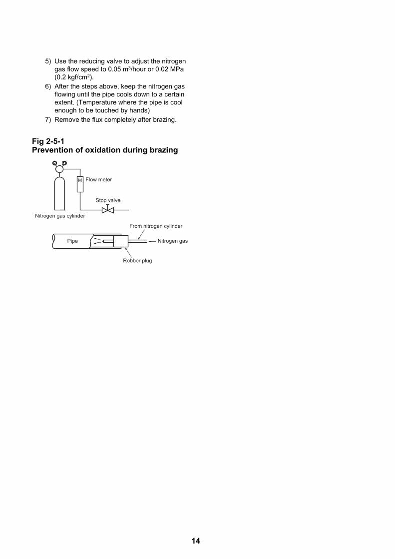
5) Use the reducing valve to adjust the nitrogen gas flow speed to 0.05 m3/hour or 0.02 MPa (0.2 kgf/cm2).
6) After the steps above, keep the nitrogen gas flowing until the pipe cools down to a certain extent. (Temperature where the pipe is cool enough to be touched by hands)
7) Remove the flux completely after brazing.
Fig 2-5-1 Prevention of oxidation during brazing
M Flow meter
Stop valve
From nitrogen cylinder
Nitrogen gas
Robber plug
Pipe
Nitrogen gas cylinder
14

3 Specifications
*1 Heating performance measurement conditions: outside air temperature 7 °C, water supply temperature 30 °C, outlet temperature 35 °C, refrigerant piping length 7.5 m (no height difference).
*2 Cooling performance measurement conditions: outside air temperature 35 °C, water supply temperature 12 °C, outlet temperature 7 °C, refrigerant piping length 7.5 m (no height difference).
*3 • The remote controller should be shipped with the hydro unit.• Use two 1.5-meter wires to connect the hydro unit with the remote controller.
*4 Check the water piping for leakage under the maximum operating pressure.*5 Do not leave the hydro unit at 5 °C or below.
Unit name Hydro unit HWS-P805XWHM3-E, P805XWHT6-E, P805XWHT9-E
Outdoor unit HWS-P805HR-E
Heating capacity *1 (kW) 8.0
Cooling capacity *2 (kW) 6.0
Variable range of compressor frequency 10 - 70 Hz
Power source Single phase 50 Hz 220-230 V
Operation mode Heating Cooling
Electric characteristic *1 *2 Hydro unit Current (A) 0.44 0.44
Power (kW) 0.06 0.06
Power factor (%) 59.3 59.3
Outdoor unit Current (A) 7.57 7.39
Power (kW) 1.62 1.58
Power factor (%) 93 93
Total Running current (A) 8.01 7.83
Operating noise sound power level Hydro unit (dB (A)) 41
Outdoor unit (dB (A)) 66
Coefficient of performance *1 *2 4.76 3.66
Hydro unit Outer dimension Height (mm) 925
Width (mm) 525
Depth (mm) 355
Net weight (kg) 49
Color Silky shade (Munsell 1Y8.5/0.5)
Remote controllerOuter dimension *3
Height (mm) 120
Width (mm) 120
Depth (mm) 16
Circulation pump Motor output (W) 125 (MAX)
Flow rate (L/min) 22.9 17.2
Type Non-self-suction centrifugal pump
Heat exchanger Plate-type heat exchange
Outdoor unit Outer dimension Height (mm) 1340
Width (mm) 900
Depth (mm) 320
Net weight (kg) 92
Color Silky shade (Munsell 1Y8.5/0.5)
Compressor Motor output (W) 2500
Type Twin rotary type with DC-inverter variable speed control
Model DA422A3F-26M
Fan motor Standard air capacity (m3/min) 103.0
Motor output (W) 100 × 2
Refrigerant piping Connection method Flare connection
Hydro unit Liquid Ø9.52
Gas Ø15.9
Outdoor unit Liquid Ø9.52
Gas Ø15.9
Maximum length (m) 30
Maximum chargeless length (m) 30
Maximum height difference (m) ±30
Minimum length (m) 5
Refrigerant Refrigerant name R410A
Charge amount (kg) 2.7
Water piping Pipe diameter R1 1/4
Maximum length (m) None (Need the flow rate 13 /min or more)
Maximum height difference (m) ±7
Maximum working water pressure (kPa) *4 430
Operating temperature range Hydro unit (°C) *5 (Cooling / Heating / Hot water) 5-32 / 5-32 / 5-32
Outdoor unit (°C) (Cooling / Heating / Hot water) 10-43 / -25-25 / -25-43
Operating humidity range Hydro unit (%) 15-85
Outdoor unit (%) 15-100
Wiring connection Power wiring 3 wires: including earth wire (Outdoor unit)
Connecting line 4 wires: including earth wire
15

*1 Heating performance measurement conditions: outside air temperature 7 °C, water supply temperature 30 °C, outlet temperature 35 °C, refrigerant piping length 7.5 m (no height difference).
*2 Cooling performance measurement conditions: outside air temperature 35 °C, water supply temperature 12 °C, outlet temperature 7 °C, refrigerant piping length 7.5 m (no height difference).
*3 • The remote controller should be shipped with the hydro unit.• Use two 1.5-meter wires to connect the hydro unit with the remote controller.
*4 Check the water piping for leakage under the maximum operating pressure.*5 Do not leave the hydro unit at 5 °C or below.
Unit name Hydro unit HWS-P1105XWHM3-E, P1105XWHT6-E, P1105XWHT9-E
Outdoor unit HWS-P1105HR-E
Heating capacity *1 (kW) 11.2
Cooling capacity *2 (kW) 10.0
Variable range of compressor frequency 10 - 90 Hz
Power source Single phase 50 Hz 220-230 V
Operation mode Heating Cooling
Electric characteristic *1 *2 Hydro unit Current (A) 0.66 0.66
Power (kW) 0.09 0.09
Power factor (%) 59.2 59.2
Outdoor unit Current (A) 10.33 14.99
Power (kW) 2.21 3.24
Power factor (%) 93 94
Total Running current (A) 10.99 15.65
Operating noise sound power level Hydro unit (dB (A)) 43
Outdoor unit (dB (A)) 66
Coefficient of performance *1 *2 4.88 3.00
Hydro unit Outer dimension Height (mm) 925
Width (mm) 525
Depth (mm) 355
Net weight (kg) 52
Color Silky shade (Munsell 1Y8.5/0.5)
Remote controllerOuter dimension *3
Height (mm) 120
Width (mm) 120
Depth (mm) 16
Circulation pump Motor output (W) 190 (MAX)
Flow rate (L/min) 32.1 28.9
Type Non-self-suction centrifugal pump
Heat exchanger Plate-type heat exchange
Outdoor unit Outer dimension Height (mm) 1340
Width (mm) 900
Depth (mm) 320
Net weight (kg) 92
Color Silky shade (Munsell 1Y8.5/0.5)
Compressor Motor output (W) 2500
Type Twin rotary type with DC-inverter variable speed control
Model DA422A3F-26M
Fan motor Standard air capacity (m3/min) 103.0
Motor output (W) 100 × 2
Refrigerant piping Connection method Flare connection
Hydro unit Liquid Ø9.52
Gas Ø15.9
Outdoor unit Liquid Ø9.52
Gas Ø15.9
Maximum length (m) 30
Maximum chargeless length (m) 30
Maximum height difference (m) ±30
Minimum length (m) 5
Refrigerant Refrigerant name R410A
Charge amount (kg) 2.7
Water piping Pipe diameter R1 1/4
Maximum length (m) None (Need the flow rate 18 /min or more)
Maximum height difference (m) ±7
Maximum working water pressure (kPa) *4 430
Operating temperature range Hydro unit (°C) *5 (Cooling / Heating / Hot water) 5-32 / 5-32 / 5-32
Outdoor unit (°C) (Cooling / Heating / Hot water) 10-43 / -25-25 / -25-43
Operating humidity range Hydro unit (%) 15-85
Outdoor unit (%) 15-100
Wiring connection Power wiring 3 wires: including earth wire (Outdoor unit)
Connecting line 4 wires: including earth wire
16

17
4 Outside drawing4-1. Hydro unitHWS-P805XWHM3-E, P805XWHT6-E, P805XWHT9-E
HWS-P1105XWHM3-E, P1105XWHT6-E, P1105XWHT9-E
960
Anc
hor b
olt l
ong
hole
pitc
h
B leg part
40
38040
2020
72.5 72.5
2-dia.12x17 long hole(for dia.8-10 anchor bolt)
2-dia.12x17 U-shape hole(for dia.8-10 anchor bolt)
A leg part
Remote controller
135.
515
8
186.
5
59.5144.5
11619.5
352
37.5
920
54
Hot water outletconnecting pipe 1 1/4"
Water inletconnecting pipe 1 1/4"
Gas line dia.15.88Liquid line dia.9.52
309.5
259
Drain nipple
371.535540
40
9Anchor bolt
long hole pitch
Manometer
525
19.5

4-2. Outdoor unitHWS-P805HR-E, P1105HR-E
96394854
60070
34
75
46
170
6038
020
0
17.5128 118 74
383
150
17.5365
40
40
12
65
83
12
95 55 1264
1
1340
320
559594 18
80 151
400
24
7 7
21
12 5595
1880 13
5
155
613
605
900
7058174581
178
178
178
518
5255
0
360655
327
60 68
534 121 534 85
Z
43.5
5-D
rain
hol
e (
20
88
burr
ing
hole
)
Air in
take
Air in
take
Air
disch
arge
Portio
n A
Portio
n BD
rain
hol
e (
25
burr
ing
hole
)
Mou
ntin
g bo
lt ho
le(
12
17
long
hol
e)
Det
ails
of p
ortio
n A
Det
ails
of p
ortio
n BM
ount
ing
bolt
hole
( 1
2 1
7 U
-sha
pe h
ole)D
escr
iptio
nN
ame
Ref
riger
ant p
ipin
g ou
tlet
Hyd
ro a
nd o
utdo
or
conn
ectin
g lin
e ou
tlet
Pow
er s
ourc
e in
take
hol
e38
kno
ckou
t hol
e
Ref
riger
ant l
iqui
d co
nnec
tion(
9
.5 fl
are)
Ref
riger
ant g
as
conn
ectio
n(
15.
9 fla
re)
Z ar
row
vie
wK
nock
out f
or lo
wer
par
t of p
ipin
g
18

19
4-3. Hot water cylinder
550
595
2066
.6 2040
550
595
1114
1090
595
1497
.6 1474
550
Specification for UK only
Specification for UK only
Specification for UK only
HWS-3001CSHM3-E(-UK) HWS-2101CSHM3-E(-UK)
HWS-1501CSHM3-E(-UK)
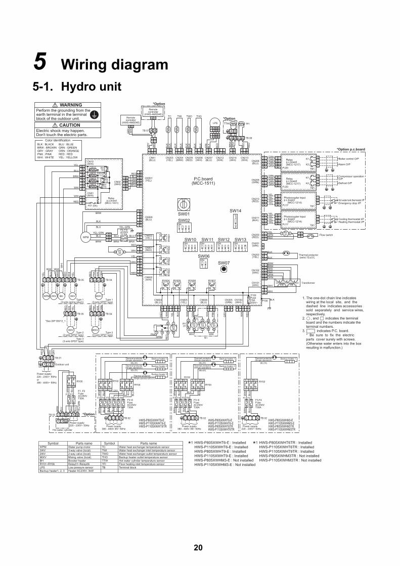
5 Wiring diagram
5-1. Hydro unit
Remotecontroller
(HWS-AMS54E)A B
GR
YW
HI
A B
Remotecontroller
(HWS-AMS54E)
*Option
TB 07
GR
Y
WH
I
BLK
BLK
BLK
BLK
BLK
BLK
BLK
BLK
1 32 1 3 42221
113
211 2
2 311 3
1 21 2
1 21 2
11
2 33 2
1 321 3
1 21 2
*OptionTHOTWOTWITC
LPS
RE
D
RE
D
BR
WB
RW
RE
D
WH
IB
LK
TFITTW
TB 06
CN208(BLU)
CN213(WHI)
CN214(WHI)
CN206(WHI)
CN205(RED)
CN204(BRW)
CN203(YEL)
CN41(BLU)
CN501(YEL)
CN207(BLU)
CN212(WHI)
CN102(WHI)
CN101(WHI)
CN202(YEL)
CN201(WHI)
CN200(RED)
CN211(BLK)
CN210(RED)
CN209(GRN)
RY607RY606RY605RY604
RY
601
RY
600
RY
603
RY
602
CN601(RED)
CN603(YEL)
CN602(WHI)
WHI
YEL
WHI
RED
RED
BRW BRW BRW
BLU BLUWPM
RY05 A1A2
P.C.board(MCC-1511)
SW10 SW11 SW12 SW13
SW06SW07
SW14SW01SW02
1 2 43
ON
ON
1 2 3 4 1 2 3 4 1 2 3 41 2 3 4
ON ON
21
ON
ON
OFFO
N
3
5
7
1
3
1
3
1
3
1
322
1
3
1
3
1
5
7
1
TB 04
MIXV
TB 04TB 05
RE
D
RE
D
OR
N
PN
KW
HI
WH
IY
EL
RE
D
OR
NW
HI
PN
K
WHI WHI
YE
L
BLU
BRW
WH
IR
ED
WH
IY
EL
BH 3WV2WVWPM
TB 055251 53 54 5655 57 5958 4241 43 44
44434241
MIXV
595857
3WV
RE
DPNKORN
4 6 82
75RY06
A1
A2
6
4
8
7
A2
A14
6RY01
WHI WHI
RY02
RY04
RY03
*1
*1 HWS-P805XWHT6-E : InstalledHWS-P1105XWHT6-E : InstalledHWS-P805XWHT9-E : InstalledHWS-P1105XWHT9-E : InstalledHWS-P805XWHM3-E : Not installedHWS-P1105XWHM3-E : Not installed
*1 HWS-P805XWHT6TR : InstalledHWS-P1105XWHT6TR : InstalledHWS-P1105XWHT9TR : InstalledHWS-P805XWHM3TR : Not installedHWS-P1105XWHM3TR : Not installed
RE
D
WH
I
GR
Y
RE
D
WH
I
BLK
YE
L
WH
I
OR
N
WH
I
PN
K
CN604(BLU)
CN605(YEL)
CN606(BLU)
CN305(GRN)
CN100(WHI)
3 13 17
7 55
311 3
1 31 3
133 3
3115
F100FuseT5A250V~
WHI
WHI
P100 BLK
ORNORNREDREDBRWBRW
RED
YELGRN
BLK
BLK
1 1
123456
1
1
1 1
456
23
1234
1
4
23
1234
1
4
23
1234
1
4
23
1234
1
4
23
1234
1
4
23
1234
1
4
23
1234
1
4
23
1234
1
4
23
3 3
323
1 1
2
23 3
12
2 21
Transformer
3
12
3
12
43
12
43
12
GRN
GRNGRN
GRN
GRN
GRNGRNGRN
YEL
YELYELYEL
YEL
YELYELYEL
*Option p.c.board
Emergency stop I/PHot water tank thermostat I/P
Cooling thermostat I/PHeating thermostat I/P
Compressor operationO/PDefrost O/P
Boiler control O/P
Alarm O/P
7 8RY01 Flow switch
Thermal protector (auto) 75 5
PJ20 TB1
K1
K2
K1
K2PJ20 TB1
PJ17 TB1
PJ17 TB1
Photocoupler input p.c.board
(MCC-1214)
Relayp.c.board(MCC-1217)
Relayp.c.board(MCC-1217)
Photocoupler input p.c.board
(MCC-1214)
WH
I
RE
D
GR
Y
TB 01
Outdoor unit
3
31 2
12111
34
2
65
1
5432
22 1
CN500(BLU)3
4
22
665
11
5 5
1 1
433
4
REDBLU
GRNORN
BRWCN02(WHI)
Relay p.c.board
(MCC-1431)F01 (5A)
CN01(WHI)
3
1 123
21 1
34556
9
78
7
9
RED
WHI
WHI
BLU
BRW
YEL
YEL-GRNBLU
CN10(WHI)
RY10
CR10
CR11
CR12
CR13
RY11
RY12
RY13
1
6D6C6B6A
A B7B7A
Type 1(3-wire SPDT type)
Type 1(2-wire spring return)
Type 2(3-wire SPST type)
Type 2(3-wire SPST type)
Type 3(3-wire SPDT type)
2 432 3 4
2 432
13 4
*See DIP SW13_1
YEL-GRN
BRW
BLU
BLK
Power supply220 - 230V~ 50Hzor380 - 400V~ 50Hz
SymbolWPM Water pump motor
2WV 2-way valve (local)
Booster heaterRelay01~Relay06
BHRY01~RY06
TWI
THOTWO
TC
TTWTFI
Parts name
3WV 3-way valve (local)
MIXV Mixing valve (local)
LPS Low pressure sensorHeater AC230V, 3kWBackup heater1, 2, 3
Water heat exchanger temperature sensorWater heat exchanger inlet temperature sensor
Terminal block
Parts nameSymbol
TBFloor heating inlet temperature sensorHot water cylinder temperature sensor
Water heat exchanger outlet temperature sensorBackup heater outlet temperature sensor
BLK : BLACK BRW : BROWNGRY : GRAYPNK : PINKWHI : WHITE
BLU : BLUEGRN : GREENORN : ORANGERED : REDYEL : YELLOW
Color identification
3 31 2 NL
1 2
TB 03
Power supply220 - 230V~ 50Hz
Hot water cylinder
*Option
BR
WB
LU
BRW
BLU
BRW
BLU
YE
L/G
RN
F1 F2F1, F2FuseAC250VT30A
RY05
2T1
1L1
4T2
3L2
F9, F10AC250VT3.15A
95 5
95 5
2T1
1L1
4T2
3L2
6T3
5L3
6T32T1 4T2
1L1 2L3 5L3
F3~8FuseAC250VT30A
RY02
F3 F4 F6F5 F8F7
BLU
GRY
GRY
BLU
BLU
BLU
BR
W
BLU
BRW
BLU
BLK
BLK
TB 02L1 L2 L3 N
Power supply380 - 400V 3N~ 50Hz
HWS-P805XWHT9-EHWS-P1105XWHT9-EHWS-P1105XWHT9TR
RY04
Backup heater 2
Backup heater 1
Backup heater 3
Thermal protector(Single operation)
Thermal protector(Single operation)
(Single operation)95 5Thermal protector
95 5
95 5
F3~6FuseAC250VT30A
BR
W
BLU
BRW
BLU
BLU
BLK
BLK
BLU
RY02
6T3
5L3
4T22T1 6T3
3L51L1 2L3 1L1 3L2
2T1 4T2
RY04
F3 F6F5F4
TB 02
Power supply380 - 400V 3N~ 50Hz
1L 2L L3 NHWS-P805XWHT6-EHWS-P1105XWHT6-EHWS-P805XWHT6TRHWS-P1105XWHT6TR
Thermal protector(Single operation)
(Single operation)Thermal protector
Backup heater 1
Backup heater 295 5
F3,F4FuseAC250VT30A
RY02
6T32T1 4T2
5L31L1 3L2
Thermal protector(Single operation)
Backup heater 1
F4F3
BR
W
BLU
BRW
BLU
L N TB 02
Power supply220 - 230V~ 50Hz
HWS-P805XWHM3-EHWS-P1105XWHM3-EHWS-P805XWHM3TRHWS-P1105XWHM3TR
WARNINGPerform the grounding from the earth terminal in the terminal block of the outdoor unit.
CAUTIONElectric shock may happen.Don't touch the electric parts.
1. The one-dot chain line indicates wiring at the local site, and the dashed line indicates accessories sold separately and service wires, respectively.
2. , and indicates the terminal board and the numbers indicate the terminal numbers.
3. indicates P.C. board. * Be sure to fix the electric
parts cover surely with screws. (Otherwise water enters into the box
resulting in malfunction.)
20

5-2. Outdoor unitHWS-P805HR-E, HWS-P1105HR-E
t°
t°
t°
t°
t°
t°
1. indicates the terminal block. Alphanumeric charactersin the cycle indicate the terminal No.
2.The two-dot chain line indicates the wiring procured locally. 3. indicates the P.C. board.4.For the hydro unit circuit, refer to the wiring diagram
of the hydro unit.
HWS-P805HR-E,HWS-P1105HR-E,
-P805HRTR-P1105HRTR
SymbolCMFM01FM02PMVTDTSTETLTO20SFSVPD49CRYL/F
Part nameCompressorFan motor
Pulse motor valvePipe temperature sensor(Discharge)Pipe temperature sensor(Suction)Heat exchanger sensor 1Heat exchanger sensor 2Outside temperature sensor4-way valve coil2-way valve coilPressure sensorCompressor case thermostatRelayLine Filter
63H High-pressure switch
SW802CN600(White)
CN710(White)
CN704(Blue)
CN701(White)
SW803
CN601(White)
CN602(Yellow)
CN603(White)
CN604(White)
RY704
CN04(White)
CN609(Blue)
SW800CN610(Yellow)
SW804
SW801
CN300(White)
Fuse, F01T25 A, 250 V ~
CN202CN201CN200P07P06
L/F
(Black)
(Red) (White)
(Red) (White) (Black)
P.C. boardMCC-1571
Fuse, F03T10 A, 250 V ~
(White) (White)(Gray) (Gray)
P04 P05
Power Supply220 - 230 V ~ 50 Hz
EarthscrewEarth
screw
Earthscrew
(Red
)
(Whi
te)
(Gra
y)
(Black)
Hydro unit
Outdoor unit
Reactor ReactorCM
U V W
123
123
FM02
49C12
12
12
12
123456
TL
TD
TO
TE
TS
12
12
1 1233
12
12
12
12
1 1233
1 2 3 4 5 61 2 3 4 6
PMV
1 3 1 41 4
20SF
1 3 51 3 5
77 P01 P02
1 2 3
1 2 3
L N
P09
ON 1
23
4
ON 1
23
4
ON 1
23
4
CN400(White)
123
123
FM01
SV
(Red)
(White)(Black) PD
P Red63H
>
>
(Gray) 3CN703
3
11
HeaterT3.15 A 250 V ~Fuse
T3.15 A 250 V ~Fuse
2 211
(White) 3CN702
3
11
(Red) 3CN606
3
11
4 4
2
21

5-3. Hot water cylinder unit
1 2TB03 (230 V)
A BTB06 (TTW)
Supply 220 - 230 V from hydro unitCable size 1.5 mm2 (minimum)
To hydro unit
Green /Yellow
BlueDouble pole thermal cut out
Blue
Brown
Brown
TTW sensor
Hot water cylinder heater
22
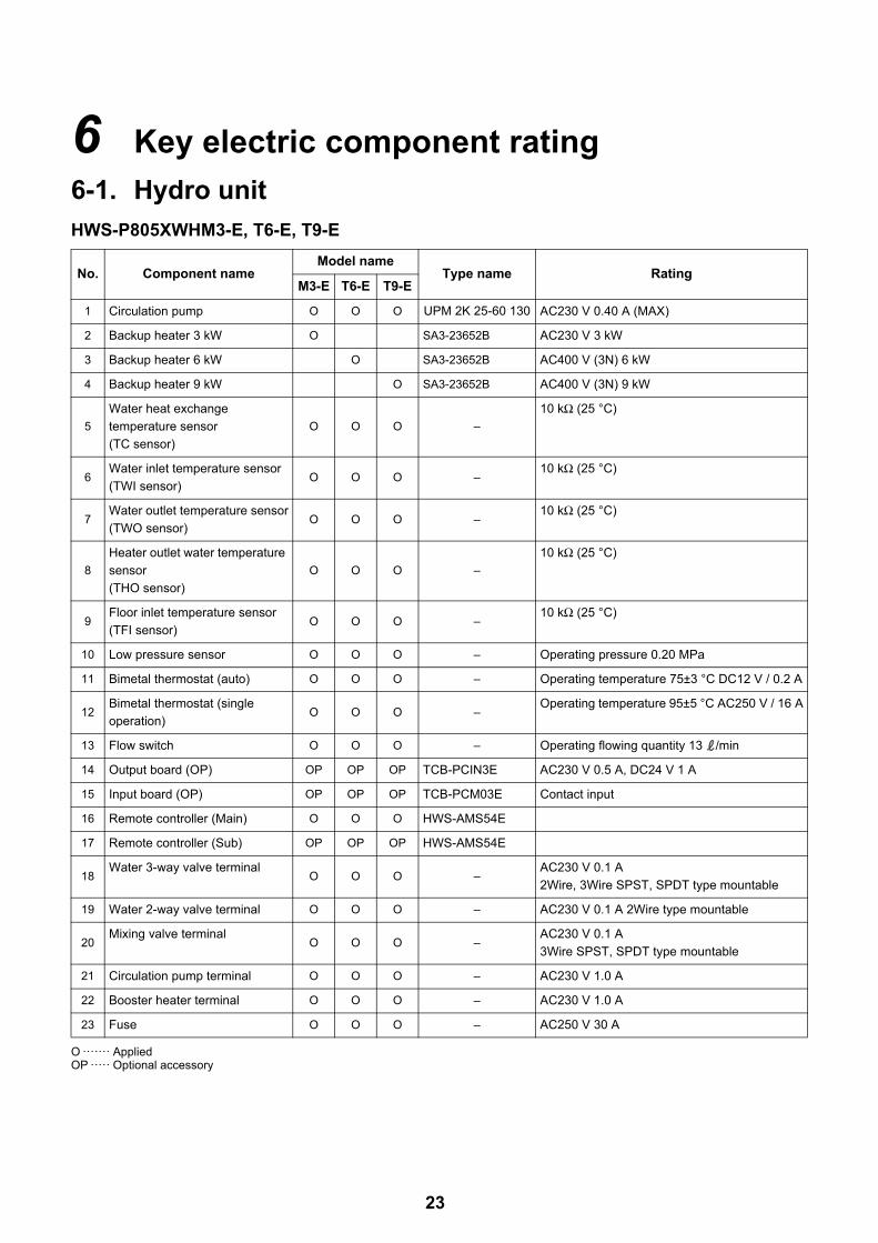
6 Key electric component rating
6-1. Hydro unitHWS-P805XWHM3-E, T6-E, T9-E
O ······· AppliedOP ····· Optional accessory
No. Component nameModel name
Type name RatingM3-E T6-E T9-E
1 Circulation pump O O O UPM 2K 25-60 130 AC230 V 0.40 A (MAX)
2 Backup heater 3 kW O SA3-23652B AC230 V 3 kW
3 Backup heater 6 kW O SA3-23652B AC400 V (3N) 6 kW
4 Backup heater 9 kW O SA3-23652B AC400 V (3N) 9 kW
5
Water heat exchange
temperature sensor
(TC sensor)
O O O –
10 kΩ (25 °C)
6Water inlet temperature sensor
(TWI sensor)O O O –
10 kΩ (25 °C)
7Water outlet temperature sensor
(TWO sensor)O O O –
10 kΩ (25 °C)
8
Heater outlet water temperature
sensor
(THO sensor)
O O O –
10 kΩ (25 °C)
9Floor inlet temperature sensor
(TFI sensor)O O O –
10 kΩ (25 °C)
10 Low pressure sensor O O O – Operating pressure 0.20 MPa
11 Bimetal thermostat (auto) O O O – Operating temperature 75±3 °C DC12 V / 0.2 A
12Bimetal thermostat (single
operation)O O O –
Operating temperature 95±5 °C AC250 V / 16 A
13 Flow switch O O O – Operating flowing quantity 13 /min
14 Output board (OP) OP OP OP TCB-PCIN3E AC230 V 0.5 A, DC24 V 1 A
15 Input board (OP) OP OP OP TCB-PCM03E Contact input
16 Remote controller (Main) O O O HWS-AMS54E
17 Remote controller (Sub) OP OP OP HWS-AMS54E
18Water 3-way valve terminal
O O O –AC230 V 0.1 A
2Wire, 3Wire SPST, SPDT type mountable
19 Water 2-way valve terminal O O O – AC230 V 0.1 A 2Wire type mountable
20Mixing valve terminal
O O O –AC230 V 0.1 A
3Wire SPST, SPDT type mountable
21 Circulation pump terminal O O O – AC230 V 1.0 A
22 Booster heater terminal O O O – AC230 V 1.0 A
23 Fuse O O O – AC250 V 30 A
23
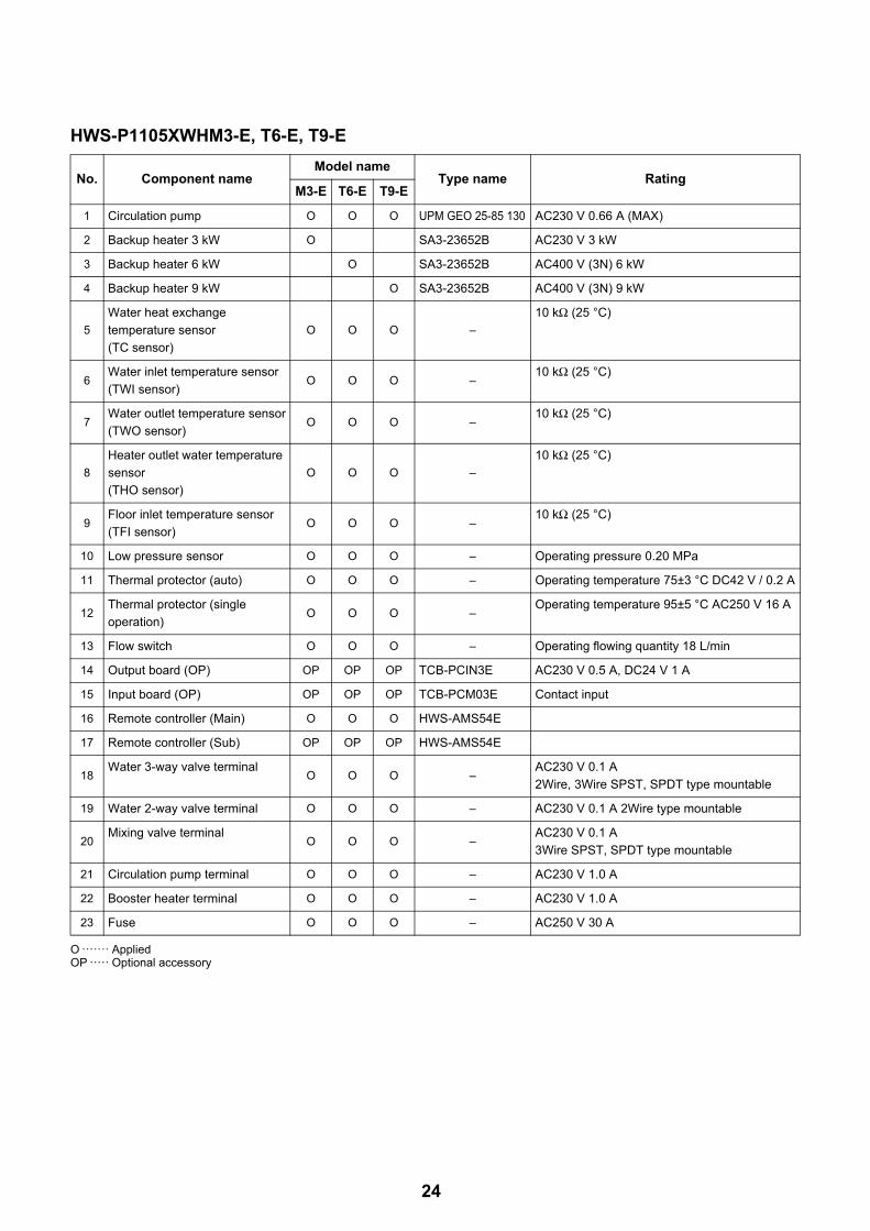
HWS-P1105XWHM3-E, T6-E, T9-E
O ······· AppliedOP ····· Optional accessory
No. Component nameModel name
Type name RatingM3-E T6-E T9-E
1 Circulation pump O O O UPM GEO 25-85 130 AC230 V 0.66 A (MAX)
2 Backup heater 3 kW O SA3-23652B AC230 V 3 kW
3 Backup heater 6 kW O SA3-23652B AC400 V (3N) 6 kW
4 Backup heater 9 kW O SA3-23652B AC400 V (3N) 9 kW
5
Water heat exchange
temperature sensor
(TC sensor)
O O O –
10 kΩ (25 °C)
6Water inlet temperature sensor
(TWI sensor)O O O –
10 kΩ (25 °C)
7Water outlet temperature sensor
(TWO sensor)O O O –
10 kΩ (25 °C)
8
Heater outlet water temperature
sensor
(THO sensor)
O O O –
10 kΩ (25 °C)
9Floor inlet temperature sensor
(TFI sensor)O O O –
10 kΩ (25 °C)
10 Low pressure sensor O O O – Operating pressure 0.20 MPa
11 Thermal protector (auto) O O O – Operating temperature 75±3 °C DC42 V / 0.2 A
12Thermal protector (single
operation)O O O –
Operating temperature 95±5 °C AC250 V 16 A
13 Flow switch O O O – Operating flowing quantity 18 L/min
14 Output board (OP) OP OP OP TCB-PCIN3E AC230 V 0.5 A, DC24 V 1 A
15 Input board (OP) OP OP OP TCB-PCM03E Contact input
16 Remote controller (Main) O O O HWS-AMS54E
17 Remote controller (Sub) OP OP OP HWS-AMS54E
18Water 3-way valve terminal
O O O –AC230 V 0.1 A
2Wire, 3Wire SPST, SPDT type mountable
19 Water 2-way valve terminal O O O – AC230 V 0.1 A 2Wire type mountable
20Mixing valve terminal
O O O –AC230 V 0.1 A
3Wire SPST, SPDT type mountable
21 Circulation pump terminal O O O – AC230 V 1.0 A
22 Booster heater terminal O O O – AC230 V 1.0 A
23 Fuse O O O – AC250 V 30 A
24

6-2. Outdoor unitHWS-P805HR-E, P1105HR-E
6-3. Hot water cylinder unit
O ······· Applied
No. Component name Type name Rating
1 Compressor DA422A3F-26M
2 Outdoor fan motor (x2) ICF-280-A100-1 Output 100 W
3 Reactor (x2) CH-44 1.4 mH, 25 A
4 4-way valve coil STF-H01AP1874A1 AC220 - 230 V full-wave rectifier input, alive time 10 sec or less
5 Pulse motor valve (PMV) coil UKV-A038 DC12 V
6 Compressor case thermostat US-622KXTMQO-SS OFF = 125 ± 4 °C, ON = 90 ± 5 °C
7 PC board MCC-1571 Input 1Ø, AC220 - 230 V ± 10%, 50/60 Hz
8 High pressure sensor NSK-BH042D-430 0 ~ 4.15 MPa
9 2-way valve coil VPV-MOAJ510B0 AC220 - 240 V
10 High pressure switch ACB-4UB154W OFF = 4.15 + 0, -0.15 MPa
No. Component name
Model name
Type name Rating1501CSHM3-E(-UK)
2101CSHM3-E(-UK)
3001CSHM3-E(-UK)
1 Hot water cylinder heater O O O – AC230 V 2.7 kW
2
Hot water cylinder temperature
sensor
(TTW sensor)
O O O –
10 kΩ (25 °C)
3Thermal cut-out
O O O –Operating temperature
Manual reset 82 °C (+3K/-2K)
25

6-4. Water heat exchange control boardHWS-P805XWHM3-E, P805XWHT6-E, P805XWHT9-EHWS-P1105XWHM3-E, P1105XWHT6-E, P1105XWHT9-E
PWM signal line connector CN500
Transformer input connectorCN101
AC power supply connectorCN100
Serial input connectorCN305
Backup heater 2 drive connectorCN606
3WV drive connectorCN602
Transformer connectorCN102
Flow switch connector CN200
Overheat protection thermostat input connectorCN202
TWO sensor connectorCN205
TWI sensor connectorCN204
THO sensor connectorCN206
TTW sensor connectorCN214
Low pressure sensor connectorCN207, CN212
Remote controller connector
CN41
TC sensor connectorCN203
TFI sensor connector CN213
Backup heater 1 drive connectorCN605
Mixing valve drive connectorCN604
Hot water cylinder drive connector
CN601
Built-in circulation pump connector
CN603
Relay board connector
CN501
Option board connector
CN208-CN211
26
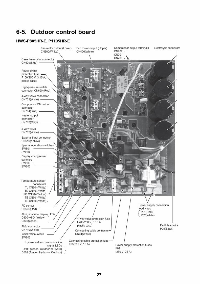
6-5. Outdoor control boardHWS-P805HR-E, P1105HR-E
Fan motor output (Upper)CN400(White)
Fan motor output (Lower)CN300(White)
Case thermostat connectorCN609(Blue)
High-pressure switch connector CN690 (Red)
Power circuit protection fuseF100(250 V, 3.15 A,plastic case)
4-way valve connectorCN701(White)
Compressor ON output connectorCN704(Blue)Heater output connectorCN703(Grey)
External input connectorCN610(Yellow)Special operation switchesSW801SW804Display change-over switchesSW800SW803
PMV connectorCN710(White)
PD sensorCN606(Red)
2-way valve CN702(White)
Initialization switchSW802
4-way valve protection fuseF700(250 V, 3.15 Aplastic case)
Power supply protection fusesF01(250 V, 25 A)
Earth lead wireP09(Black)Connecting cable connector
CN04(White)
Connecting cable protection fuse F03(250 V, 10 A)
Electrolytic capacitorsCompressor output terminalsCN202CN201CN200
Power supply connection lead wires P01(Red) P02(White)
Temperature sensor connectors
TL CN604(White)TD CN603(White)
TO CN602(Yellow)TE CN601(White)TS CN600(White)
Alive, abnormal display LEDsD800 804(Yellow)D805(Green)
Hydro-outdoor communication signal LEDs
D503 (Green, Outdoor =>Hydro)D502 (Amber, Hydro => Outdoor)
27

28
7 Refrigeration cycle / Water system diagram 7-1. Water system diagram
M
M
Fan
coil
unit
Rad
iato
r uni
t
Floo
r
hea
ting
By-p
ass
valv
e(lo
cally
pro
cure
d)
By-p
ass
valv
e(lo
cally
pro
cure
d)
Mot
oriz
ed m
ixin
g va
lve
(loca
lly p
rocu
red)
AC23
0 V
Buffe
r tan
k (lo
cally
pro
cure
d)
Circ
ulat
ion
pum
p(lo
cally
pro
cure
d)
Circ
ulat
ion
pum
pm
ax :
10 b
ar
Stra
iner
(loca
lly p
rocu
red)
40 m
esh
Mot
oriz
ed 3
-way
val
ve(lo
cally
pro
cure
d)AC
230
V
Boos
ter h
eate
r(lo
cal)
2-w
ay v
alve
for
cool
ing
mod
e(lo
cally
pro
cure
d)AC
230
V
Safe
ty v
alve
set :
3.5
bar
Boile
r(lo
cal)
Drain
cock
for w
ater
char
ge(lo
cally
pro
cure
d)
Cyl
inde
r hea
ter
Ø1
: 2.7
kW
Rel
ief v
alve
(UK)
90 °C
10 b
arW
ater
out
let
Wat
er in
let
Red
ucin
gva
lve
(UK
)3.
5 ba
r
Pres
sure
relie
fSe
t val
ue :
7 ba
r (U
K)
Wat
er h
eat e
xcha
nger
max
: 10
bar
Back
up h
eate
rØ
1 : 3
kW
Ø3
: 6 k
WØ
3 : 9
kW
Flow
sw
Ther
mal
pro
tect
or(a
uto)
set :
75
± 3
°C
Ther
mal
pro
tect
orSi
ngle
ope
ratio
nse
t : 9
5 ±
5 °C
Low
pres
sure
sens
or
Expa
nsion
vess
else
t : 1
bar
Over
pres
sure
pre
vent
ive
valve
set :
4.3
bar
Man
omet
erga
ge :
6bar
Wat
er v
ent
valv
e
Air v
ent v
alve
Out
door
uni
t
Ther
mal
cut
-out
(man
ual r
eset
)82
°C (+
3K/-2
K)
zone
1
zone
2
TFI
TTW
TC
TWO
THO
TWI
Hot
wat
er c
ylin
der
Loca
l hot
water
syste
m

Installation example of water circuit
The water flowing for a system without buffer tank ((1), (2), (3), (5)) requires18 /min (P805XWH 13 /min) or more. This water flowing requires 5 or more branches of Floor heating or Radiator etc.Less than 5 branches may cause a flow deficiency. In this case, please provide a buffer tank and secondary pumps as shown in (4). Please check how to install the boiler (See page 40)
(1) (2)
(3) (4)
(5) (6)
29
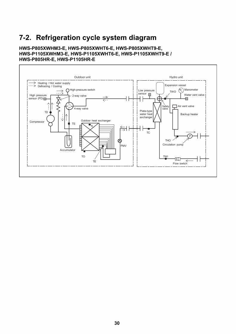
7-2. Refrigeration cycle system diagramHWS-P805XWHM3-E, HWS-P805XWHT6-E, HWS-P805XWHT9-E,HWS-P1105XWHM3-E, HWS-P1105XWHT6-E, HWS-P1105XWHT9-E / HWS-P805HR-E, HWS-P1105HR-E
Outdoor unit
TS
TD
AccumulatorPMV
TO
Flow switch
Plate-typewater heatexchanger
Air vent valve
Manometer
P
Expansion vessel
High pressuresensor (PD)
High-pressure switch
TE
Low pressuresensor
TWOWater vent valve
Backup heater
TWI
Circulation pumpTHO
TL
4-way valve
TC
Hydro unit
Outdoor heat exchangerCompressor
2-way valve
Heating / Hot water supplyDefrosting / Cooling
Safety valve
30
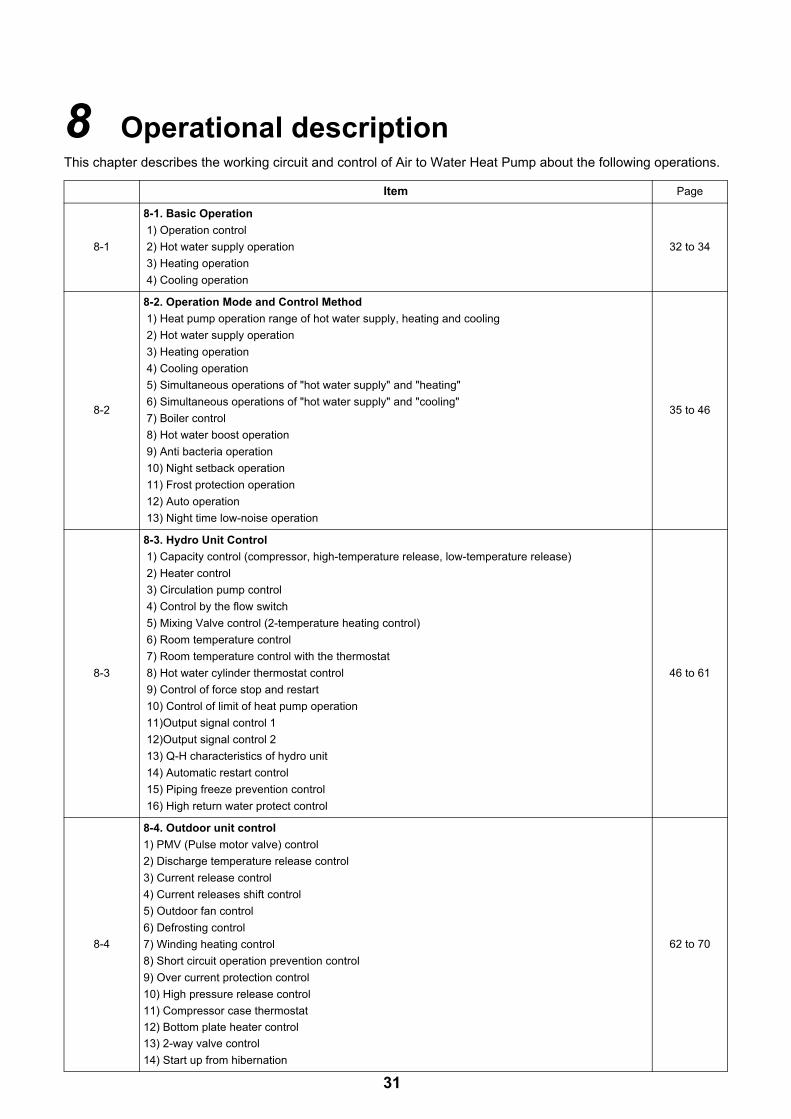
8 Operational descriptionThis chapter describes the working circuit and control of Air to Water Heat Pump about the following operations.
Item Page
8-1
8-1. Basic Operation
1) Operation control
2) Hot water supply operation
3) Heating operation
4) Cooling operation
32 to 34
8-2
8-2. Operation Mode and Control Method
1) Heat pump operation range of hot water supply, heating and cooling
2) Hot water supply operation
3) Heating operation
4) Cooling operation
5) Simultaneous operations of "hot water supply" and "heating"
6) Simultaneous operations of "hot water supply" and "cooling"
7) Boiler control
8) Hot water boost operation
9) Anti bacteria operation
10) Night setback operation
11) Frost protection operation
12) Auto operation
13) Night time low-noise operation
35 to 46
8-3
8-3. Hydro Unit Control
1) Capacity control (compressor, high-temperature release, low-temperature release)
2) Heater control
3) Circulation pump control
4) Control by the flow switch
5) Mixing Valve control (2-temperature heating control)
6) Room temperature control
7) Room temperature control with the thermostat
8) Hot water cylinder thermostat control
9) Control of force stop and restart
10) Control of limit of heat pump operation
11)Output signal control 1
12)Output signal control 2
13) Q-H characteristics of hydro unit
14) Automatic restart control
15) Piping freeze prevention control
16) High return water protect control
46 to 61
8-4
8-4. Outdoor unit control
1) PMV (Pulse motor valve) control
2) Discharge temperature release control
3) Current release control
4) Current releases shift control
5) Outdoor fan control
6) Defrosting control
7) Winding heating control
8) Short circuit operation prevention control
9) Over current protection control
10) High pressure release control
11) Compressor case thermostat
12) Bottom plate heater control
13) 2-way valve control
14) Start up from hibernation
62 to 70
31

Item Operation flow and applicable data, etc. Operation description
8-1.Basic Operation
1) Operation controlRemote controller
1. PurposeThe operations of the hydro unit and the outdoor unit are controlled according to user-defined operation condition settings.
2. DetailsThe operation controls include those shown on the left.
3. Operations1) An operation condition
is selected with the remote controller.
2) Setting the remote controller button to “ON” transmits a signal to the hydro unit.
3) The hydro unit controller controls the operations shown on the left while also controlling the water 2-way valve, water 3-way valve, circulation pump, mixing valve, hot water cylinder heater, and backup heater.
4) The hydro unit controller transmits an operation instruction to the outdoor unit, and uses serial signals to transmit and receive control statuses.
5) The outdoor unit control unit performs the operation controls shown on the left while also controlling the compressor, outdoor fan motor, pulse motor valve, 4-way valve, 2-way valve, and bottom plate heater.
Operation condition selection
Serial signals transmit and receive
Heating: Run/StopHot water supply: Run/StopCooling: Run/Stop
Serial signals transmit and receive
Serial signals transmit and receive
Remote controller settings <Heating> Temperature setting <Hot water supply > Temperature setting <Cooling> Temperature setting
Auto Temp Anti bacteria Frost protection Hot water boost
Water heat exchange Sub board
Outdoor unit control
Serial signals transmit and receive
Outdoor unit control Inverter frequency control Waveform synthesis function Calculation function (Temperature calculation) AD conversion function Rapid heating function Compressor restart Delay function G-Tr overcurrent prevention function Defrosting operation function
Hydro unit
Outdoor unit
CompressorOutdoor fan motor
PD sensorTD sensorTS sensorTE sensorTO sensorPMV4-way valve2-way valveBottom plate heaterHigh pressure switch
Thermostat (Cooling/Heating)
Forcible stop input
Error Alarm stop outputDefrosting outputOperation outputBoiler "ON/OFF" Booster Heater
Water heat exchange control board
Inverter
Condensed temperature sensor (TC)Water inlet temperature sensor (TWI)Water outlet temperature sensor (TWO)Water heater outlet temperature sensor (THO)Hot water cylinder sensor (TTW)Floor inlet sensor (TFI)Overheat prevention thermostat Flow switchHot water cylinder heaterBackup heater 1 power-relayBackup heater 2 power-relay
Pump 1 (Built-in circulation pump)
2WV_W3WV_W
Mixing Valve
Low pressure sensor
AC 220~230 V for Hot water cylinder heater
AC 220 - 230 V for heat pump
AC 380~400 V (3N~) for Back up heater
Serial communication
Hot water supply heater MG
32

8-1.Basic Operation
2) Hot water supply operation Hot water supply operation1. Purpose
Hot water supply2. Details
This section performs hot water supply operation according to heating conditions specified for the steps on the left.
3. Operations1) By pressing the [ ]
button on the remote controller, the hydro unit controller starts to transmit a hot water supply operation signal to the outdoor unit.
2) The hydro unit performs the operation controls shown on the left while also controlling the circulation pump, hot water cylinder heater “3WV”.
3) The outdoor unit controls the compressor, outdoor fan motor, electric expansion valve, and 4-way valve based on the operation signals transmitted by the hydro unit.
3) Heating operation Heating operation1. Purpose
Heating2. Details
This section performs heating operation according to heating conditions specified for the steps on the left.
3. Operations1) By pressing the [ ]
button on the remote controller, the hydro unit controller starts to transmit a heating operation signal to the outdoor unit.
2) The hydro unit performs the operation controls shown on the left while also controlling the circulation pump, backup booster heater “ON/OFF”, water 2-way valve, and water 3-way valve.
3) The outdoor unit controls the compressor, outdoor fan motor, electric expansion valve, and 4-way valve based on the operation signals transmitted by the hydro unit.
Item Operation flow and applicable data, etc. Operation description
Hydro unit control
Circulation pump "ON/OFF" control Water 3-way valve control Hot water cylinder heater control
Hot water temperature: 40 °C to 75 °C
Number of compressor revolutions control Number of outdoor fan motor revolutions control Pulse motor valve control 4-way valve control
Outdoor unit control
Operation instruction signal transmit
Hot water supply operation start
Hydro unit control
Circulation pump "ON/OFF" control Water 3-way valve control Water 2-way valve control Mixing Valve control Backup heater control Booster heater control
Heating temperature: 20 °C to 60 °C
Number of compressor revolutions control Number of outdoor fan motor revolutions control Pulse motor valve control 4-way valve control
Outdoor unit control
Operation instruction signal transmit
Heating operation start
33
8-1.Basic Operation
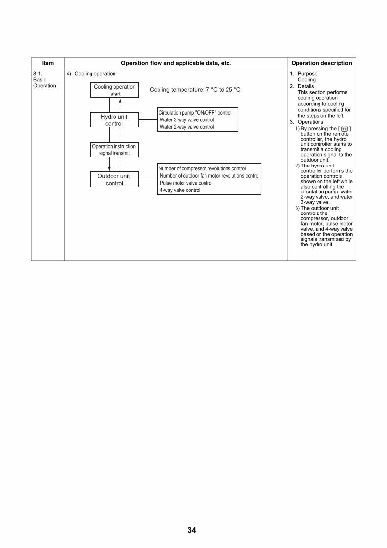
4) Cooling operation 1. PurposeCooling
2. DetailsThis section performs cooling operation according to cooling conditions specified for the steps on the left.
3. Operations1) By pressing the [ ]
button on the remote controller, the hydro unit controller starts to transmit a cooling operation signal to the outdoor unit.
2) The hydro unit controller performs the operation controls shown on the left while also controlling the circulation pump, water 2-way valve, and water 3-way valve.
3) The outdoor unit controls the compressor, outdoor fan motor, pulse motor valve, and 4-way valve based on the operation signals transmitted by the hydro unit.
Item Operation flow and applicable data, etc. Operation description
Hydro unit control
Circulation pump "ON/OFF" control Water 3-way valve control Water 2-way valve control
Cooling temperature: 7 °C to 25 °C
Number of compressor revolutions control Number of outdoor fan motor revolutions control Pulse motor valve control 4-way valve control
Outdoor unit control
Operation instruction signal transmit
Cooling operation start
34
Item Operation flow and applicable data, etc.
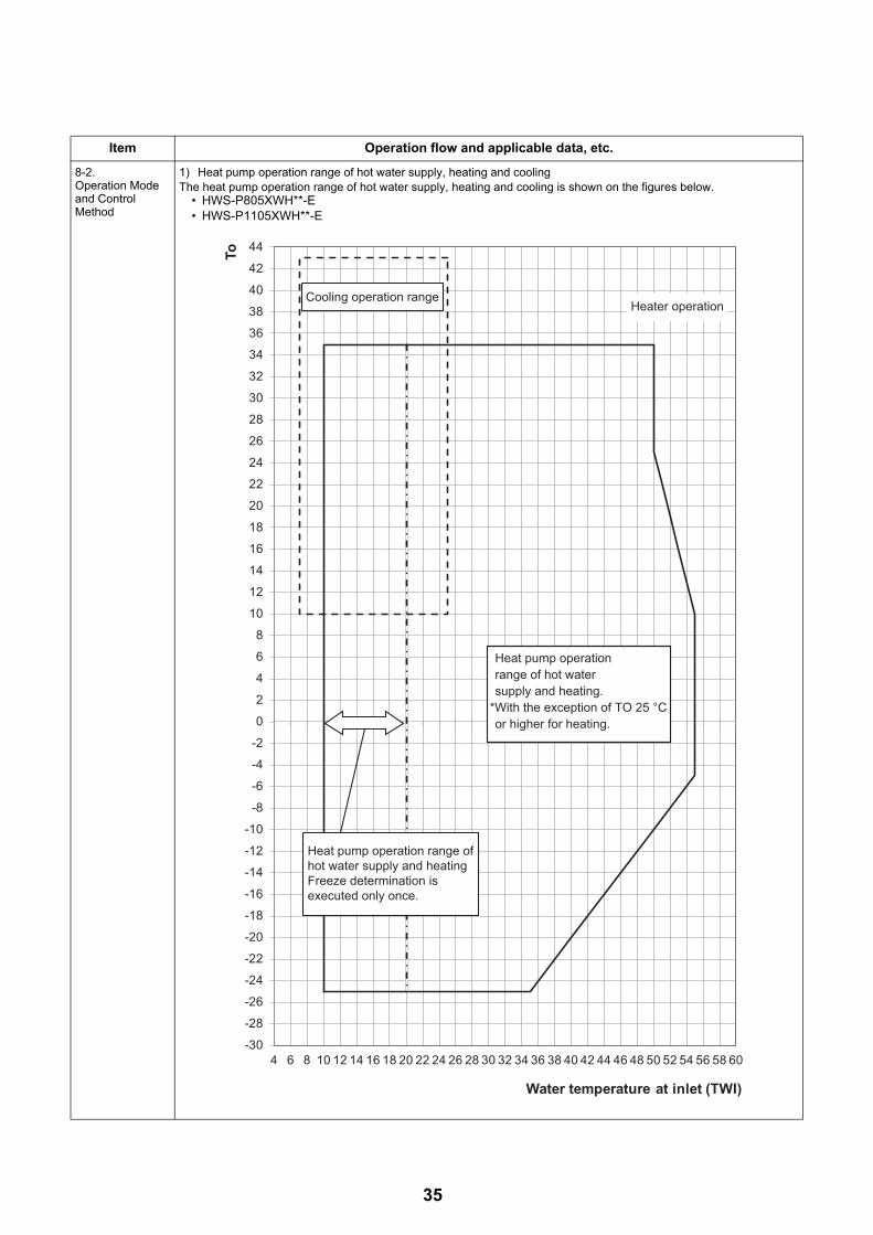
8-2.Operation Mode and Control Method
1) Heat pump operation range of hot water supply, heating and coolingThe heat pump operation range of hot water supply, heating and cooling is shown on the figures below.
• HWS-P805XWH**-E• HWS-P1105XWH**-E
-30
-28
-26
-24
-22
-20
-18
-16
-14
-12
-10
-8
-6
-4
-2
0
2
4
6
8
10
12
14
16
18
20
22
24
26
28
30
32
34
36
38
40
42
44
4 6 8 10 12 14 16 18 20 22 24 26 28 30 32 34 36 38 40 42 44 46 48 50 52 54 56 58 60
To
Water temperature at inlet (TWI)
Cooling operation range
Heat pump operationrange of hot watersupply and heating.
*With the exception of TO 25 °Cor higher for heating.
Heater operation
Heat pump operation range of hot water supply and heating Freeze determination is executed only once.
35

8-2.Operation Mode and Control Method
The following shows the operation modes and controlled objects.
O Possible× Not possible
2) Hot water supply operation1) Operation start condition
When the [ ] remote controller button is pressed and the following operation start condition is met, the operation starts.• TTW < 38 °C is detected.
2) Operation mode determinationAn operation mode is determined according to the temperature of TTW sensor.• Heat pump operation selection *1 *2• When TTW < 38 °C (a zone in the right figure) is met, the
heat pump operation is selected.• Heater operation selection
When 45 °C ≤ TTW < TSC_H (b zone in the right figure) is met, the heater operation is selected.
• Thermostat status "OFF" selectionWhen TTW ≥ TSC_H is met, the thermostat status "OFF" is selected.
3) Operation stopThe operation stops in the following cases.• The remote controller gives a stop instruction. • TTW ≥ TSC_H is met.
*1: When the outside temperature is -25 °C or below, the heater operation is selected even if the TTW temperature falls into "a zone".
*2: When "Hot water supply" and "Heating" are simultaneously in operation, the heater operation may be selected depending on the outside air temperature.
Related FC
*3:When the outside temperature is 0 °C or below, the boil-up temperature will be higher that setting temperature in hot water supply mode.
Item Operation flow and applicable data, etc.
Operationmode
Controlled object
Cooling only
Heating only
Hot water
supply only
Heating and Hot water both operate Cooling and Hot water both operate
Heat pump select for heating
Heat pump select for hot water
supply
Heat pump select for cooling
Heat pump select for hot water
supply
Heating side
Hot water
supply side
Heating side
Hot water
supply side
Cooling side
Hot water
supply side
Cooling side
Hot water
supply side
Heat pump O O O O × × O O × × O
Backup heater
× O × O × × × × × × ×
Hot water cylinder heater
× × O × O × O × O × O
(Hot water cylinder unit)
TTW sensor
TTW
HP_H OFF 45 °CHP_H ON 38 °C
TSC_H(Temperature set with
remote controller)Thermostat OFF c Zone
a Zone
Heater operationb Zone
Heat pump operation
TSC_H is hot water temperature set with remote controller
FC No. Setting item Default Setting available range
1E Upper limit of hot water supply temperature 75 °C 60-80 °C
1F Lower limit of hot water supply temperature 40 °C 40-60 °C
20 Heat pump start temperature 38 °C 20-45 °C
21 Heat pump end temperature 45 °C 40-50 °C
24 Outside air correction start temperature for hot water supply*3 0 °C -20-10 °C
25 Outside air correction temperature for hot water supply*3 3 degree 0 -15 degree
36

8-2.Operation Mode and Control Method
3) Heating operation<Operation only for ZONE1>• This operation is enabled when DP_SW12_2 ZONE1 is set to "OFF" (default).• The remote controller displays settings, and only the set temperature of can be changed.
<Operation for ZONE1 and ZONE2 (2 temperatures control)>• This operation is enabled when DP_SW12_2 ZONE1 is set to "OFF" (default) and DP_SW12_3 ZONE2 to "ON".• The remote controller displays settings, and the set temperatures of
can be changed.• To set temperatures for and , use SELECT to switch between and
.• For 2 zone temperatures control, the flow adjustment of MIXING VALVE controls the water temperature of
. For details, see the description on MIXING VALVE control in 8-3-5. (See page 52)
1) Operation start conditionPressing the [ ] button of remote controller starts a heating operation. *1 *2
2) Operation mode selectionAn operation mode is determined according to the temperature of TWI sensor.• Heat pump operation selection *1 *2
When TWI < TSC_F (d zone in the right figure) is met, the heat pump operation is selected.
• Thermostat status "OFF"When TWI ≥ TSC_F (e zone in the right figure) is met, the thermostat status "OFF" is selected.
3)Operation stop conditionWhen the following condition is met, the heating operation stops.
• The remote controller gives a stop instruction.
*1: When the outside temperature is -25 °C or below, the heater operation is selected even if the TWI temperature falls into "d zone".
*2: When "Hot water supply" and "Heating" are simultaneously in operation, the heater operation may be selected depending on the outside air temperature.
Related FC
Item Operation flow and applicable data, etc.
TWI
TSC_F
Thermostat off operation
e zone
d zonediff2K
Heat pump operation
TSC_F is a heating temperature set with remote controller
FC No. Setting item Default Setting available range
1A Upper limit of heating (Zone1) limited temperature 60 37-60 °C
1B Lower limit of heating (Zone1) limited temperature 20 20-37 °C
1C Upper limit of heating (Zone2) limited temperature 60 37-60 °C
1D Lower limit of heating (Zone2) limited temperature 20 20-37 °C
37
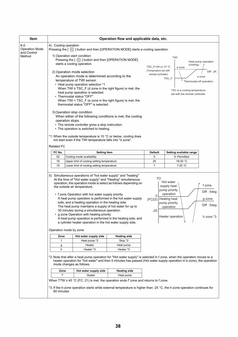
8-2.Operation Mode and Control Method
4) Cooling operationPressing the [ ] button and then [OPERATION MODE] starts a cooling operation.
1) Operation start conditionPressing the [ ] button and then [OPERATION MODE] starts a cooling operation.
2) Operation mode selectionAn operation mode is determined according to the temperature of TWI sensor.• Heat pump operation selection *1
When TWI ≥ TSC_F (d zone in the right figure) is met, the heat pump operation is selected.
• Thermostat status "OFF"When TWI < TSC_F (e zone in the right figure) is met, the thermostat status "OFF" is selected.
3) Operation stop conditionWhen either of the following conditions is met, the cooling operation stops.• The remote controller gives a stop instruction. • The operation is switched to heating.
*1: When the outside temperature is 10 °C or below, cooling does not start even if the TWI temperature falls into "d zone".
Related FC
5) Simultaneous operations of "hot water supply" and "heating"At the time of "Hot water supply" and "Heating" simultaneous operation, the operation mode is select as follows depending on the outside air temperature.
• f zone Operation with hot water supply priorityA heat pump operation is performed in the hot water supply side, and a heating operation in the heating side. The heat pump maintains a supply of hot water for up to 30 minutes during a simultaneous operation.
• g zone Operation with heating priorityA heat pump operation is performed in the heating side, and a cylinder heater operation in the hot water supply side.
Operation mode by zone
*2: Note that after a heat pump operation for "Hot water supply" is selected in f zone, when the operation moves to a heater operation for "hot water" and then 5 minutes has passed (Hot water supply operation in b zone), the operation mode changes as follows.
When TTW ≥ 45 °C (FC: 21) is met, the operation ends f' zone and returns to f zone.
*3: If the h-zone operation starts while external temperature is higher than -25 °C, the h-zone operation continues for 60 minutes.
Item Operation flow and applicable data, etc.
TWI
TSC_F+2K or 12 °C(Temperature set with
remote controller)TSC_F
Thermostat off operation
Heat pump operation (cooling)
e zone
Diff : 2K
d zone
TSC is a cooling temperature set with the remote controller
FC No. Setting item Default Setting available range
02 Cooling mode availability 0 0: Permitted
18 Upper limit of cooling setting temperature 25 18-30 °C
19 Lower limit of cooling setting temperature 7 7-20 °C
Zone Hot water supply side Heating side
f Heat pump *2 Stop *2
g Heater Heat pump
h Heater *3 Heater *3
0(FC22)
-25
Diff : 5deg
f zone
h zone *3
Diff : 5deg
g zone
Heater operation
Hot water supply heat
pump priority operation
Heating heat pump priority
operation
TO
Zone Hot water supply side Heating side
f' Heater Heat pump
38
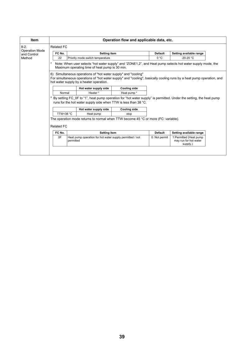
8-2.Operation Mode and Control Method
Related FC
* Note: When user selects “hot water supply” and “ZONE1,2”, and Heat pump selects hot water supply mode, the Maximum operating time of heat pump is 30 min.
6) Simultaneous operations of "hot water supply" and "cooling"For simultaneous operations of "hot water supply" and "cooling", basically cooling runs by a heat pump operation, and hot water supply by a heater operation.
* By setting FC_0F to “1”, heat pump operation for “hot water supply” is permitted. Under the setting, the heat pump runs for the hot water supply side when TTW is less than 38 °C.
The operation mode returns to normal when TTW become 45 °C or more (FC: variable).
Related FC
Item Operation flow and applicable data, etc.
FC No. Setting item Default Setting available range
22 Priority mode switch temperature 0 °C -20-20 °C
Hot water supply side Cooling side
Normal Heater * Heat pump *
Hot water supply side Cooling side
TTW<38 °C Heat pump stop
FC No. Setting item Default Setting available range
0F Heat pump operation for hot water supply permitted / not permitted
0: Not permit 1:Permitted (Heat pump may run for hot water
supply.)
39
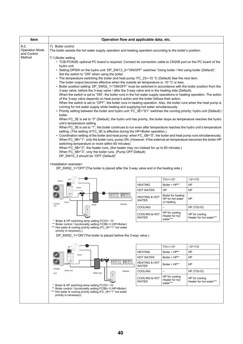
8-2.Operation Mode and Control Method
7) Boiler controlThe boiler assists the hot water supply operation and heating operation according to the boiler’s position.
7-1) Boiler setting• TCB-PCIN3E optional PC board is required. Connect its connection cable to CN208 port on the PC board of the
hydro unit.• Setting DPSW on the hydro unit: DP_SW13_2=”ON/OFF” switches “Using boiler / Not using boiler (Default)”.
Set the switch to “ON” when using the boiler.• The temperature switching the boiler and heat pump: FC_23=-10 °C (Default) See the next item.
The boiler output becomes effective when the outside air temperature is -10 °C or less.• Boiler position setting: DP_SW02_1=”ON/OFF” must be switched in accordance with the boiler position from the
3-way valve; before the 3-way valve / after the 3-way valve and in the heating side (Default).When the switch is set to “ON”, the boiler runs in the hot water supply operations or heating operation. The action of the 3-way valve depends on heat pump’s action and the boiler follows their action.When the switch is set to “OFF”, the boiler runs in heating operation. Also, the boiler runs when the heat pump is running for hot water supply while heating and supplying hot water simultaneously.
• Priority setting between the boiler and hydro unit: FC_3E=”0/1” switches the running priority; hydro unit (Default) /boiler. When FC_3E is set to “0” (Default), the hydro unit has priority, the boiler stops as temperature reaches the hydro unit’s temperature setting.When FC_3E is set to “1”, the boiler continues to run even after temperature reaches the hydro unit’s temperature setting. (The setting of FC_3E is effective during the HP+Boiler operation.)
• Coordination setting of the boiler and heat pump: when FC_5B=”0”, the boiler and heat pump runs simultaneously. When FC_5B=”1”, only the boiler runs, pump ON. (However, if the external air temperature becomes the boiler-HP switching temperature or more within 60 minutes)When FC_5B=”2”, the heater runs. (the heater may run instead for up to 60 minutes.)When FC_5B=”3”, only the boiler runs. (Pump OFF:Default)DP_SW10_3 should be “OFF (Default)”
<Installation example>DP_SW02_1=“OFF”(The boiler is placed after the 3-way valve and in the heating side.)
DP_SW02_1=“ON”(The boiler is placed before the 3-way valve.)
Item Operation flow and applicable data, etc.
Boiler
Outdoorunit
HydroBuffer Radiator
Option TO<=-10* -10*<TO
HEATING Boiler + HP** HP
HOT WATER HP HP
HEATING & HOT WATER
Boiler for heatingHP for hot water or heating
HP
COOLING – HP (TO≥10)
COOLING & HOT WATER
HP for coolingHeater for hot water***
HP for coolingHeater for hot water***
* Boiler & HP switching temp setting FC23= -10 ** Boiler control / functionality setting FC5B= 0 (HP+Boiler)*** Hot water & cooling priority setting (FC_0F=“1” hot water
priority is necessary.)
Boiler
Outdoor
UnitHydro unit
Buffer tankRadiator
TO<=-10* -10*<TO
HEATING Boiler + HP** HP
HOT WATER Boiler + HP** HP
HEATING & HOT WATER
Boiler + HP** HP
COOLING – HP (TO≥10)
COOLING & HOT WATER
HP for coolingHeater for hot water***
HP for coolingHeater for hot water***
* Boiler & HP switching temp setting FC23= -10 ** Boiler control / functionality setting FC5B= 0 (HP+Boiler)*** Hot water & cooling priority setting (FC_0F=“1” hot water
priority is necessary)
40
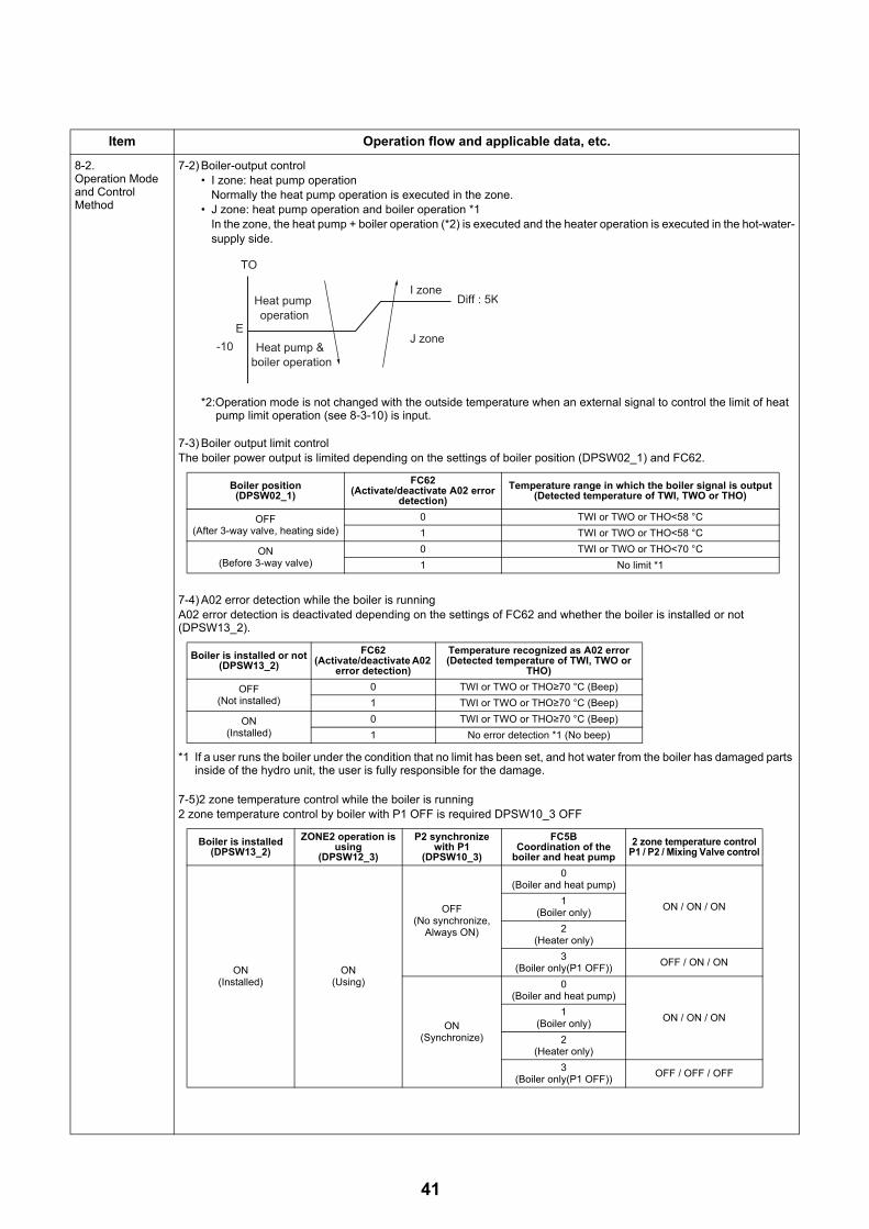
8-2.Operation Mode and Control Method
7-2) Boiler-output control• I zone: heat pump operation
Normally the heat pump operation is executed in the zone.• J zone: heat pump operation and boiler operation *1
In the zone, the heat pump + boiler operation (*2) is executed and the heater operation is executed in the hot-water-supply side.
*2:Operation mode is not changed with the outside temperature when an external signal to control the limit of heat pump limit operation (see 8-3-10) is input.
7-3) Boiler output limit controlThe boiler power output is limited depending on the settings of boiler position (DPSW02_1) and FC62.
7-4) A02 error detection while the boiler is runningA02 error detection is deactivated depending on the settings of FC62 and whether the boiler is installed or not (DPSW13_2).
*1 If a user runs the boiler under the condition that no limit has been set, and hot water from the boiler has damaged parts inside of the hydro unit, the user is fully responsible for the damage.
7-5)2 zone temperature control while the boiler is running2 zone temperature control by boiler with P1 OFF is required DPSW10_3 OFF
Item Operation flow and applicable data, etc.
E-10
I zone
J zone
Heat pump operation
Heat pump & boiler operation
TO
Diff : 5K
Boiler position(DPSW02_1)
FC62(Activate/deactivate A02 error
detection)
Temperature range in which the boiler signal is output(Detected temperature of TWI, TWO or THO)
OFF(After 3-way valve, heating side)
0 TWI or TWO or THO<58 °C
1 TWI or TWO or THO<58 °C
ON(Before 3-way valve)
0 TWI or TWO or THO<70 °C
1 No limit *1
Boiler is installed or not(DPSW13_2)
FC62(Activate/deactivate A02
error detection)
Temperature recognized as A02 error(Detected temperature of TWI, TWO or
THO)
OFF(Not installed)
0 TWI or TWO or THO≥70 °C (Beep)
1 TWI or TWO or THO≥70 °C (Beep)
ON(Installed)
0 TWI or TWO or THO≥70 °C (Beep)
1 No error detection *1 (No beep)
Boiler is installed(DPSW13_2)
ZONE2 operation is using
(DPSW12_3)
P2 synchronize with P1
(DPSW10_3)
FC5BCoordination of the
boiler and heat pump
2 zone temperature controlP1 / P2 / Mixing Valve control
ON(Installed)
ON(Using)
OFF(No synchronize,
Always ON)
0(Boiler and heat pump)
ON / ON / ON1
(Boiler only)
2(Heater only)
3(Boiler only(P1 OFF))
OFF / ON / ON
ON(Synchronize)
0(Boiler and heat pump)
ON / ON / ON1
(Boiler only)
2(Heater only)
3(Boiler only(P1 OFF))
OFF / OFF / OFF
41

8-2.Operation Mode and Control Method
Related FC
8) Hot water boost operationA Hot water boost operation heats the water quickly to the set temperature TSC_H = 75 °C (FC_09).
1) How to operate• When pressing the [Hot water boost] button after pressing the remote controller [ ] button, a heat pump operation
in progress in the heating side switches to in the hot water side, and continues the operation regardless of the hot water supply start condition, TTW < 38 °C. In addition, the hot water cylinder is immediately energized to start a Hot water supply operation under TSC_H = 75 °C.
• A Hot water boost operation returns to the usual operation after 60 minutes passed or reached 75 °C.• The remote controller display during a Hot water boost operation is the same as the set temperature display of a
usual Hot water supply operation.• The usual set temperature change is used for changing the set temperature during a Hot water boost operation.
Change the BOOST set temperature with FC_09, if necessary.
Related FC
Item Operation flow and applicable data, etc.
FC No. Setting item Default Variable range
23 Boiler-heat pump switching temperature -10 °C -20-20 °C
3E Control priority between the hydro unit and boiler(Control valid for operating heat pump mode)
0: Hydro unit control Independent temperature control for the hydro unit and boiler
5B Coordination of the boiler and heat pump 3: Boiler only (Pump OFF) 0: Boiler and Heat pump1: Boiler only2: Heater only
62 Activate/deactivate A02 error detection 0: Activate 1: Deactivate
75 °C hot water operation (FC_09)
Switches to Hot water supply operation
60 minutes operating time (FC_08)
Usual operation
HOT WATER button set to "ON"
Hot water boost button set to "ON"
Current heat pump operation
Heating side
Hot water supply side
FC No. Setting item Default Setting available range
09 Hot water boost set temperature 75 °C 40-80 °C
08 Hot water boost operation time 60 min 30-180 minEvery 10 min
42
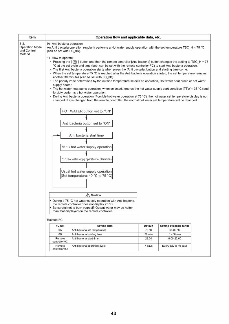
8-2.Operation Mode and Control Method
9) Anti bacteria operationAn Anti bacteria operation regularly performs a Hot water supply operation with the set temperature TSC_H = 75 °C (can be set with FC_0A).
1) How to operate• Pressing the [ ] button and then the remote controller [Anti bacteria] button changes the setting to TSC_H = 75
°C at the set cycle and time (both can be set with the remote controller FC) to start Anti bacteria operation.• The first Anti bacteria operation starts when press the [Anti bacteria] button and starting time come.• When the set temperature 75 °C is reached after the Anti bacteria operation started, the set temperature remains
another 30 minutes (can be set with FC_0B).• The priority zone determined by the outside temperature selects an operation, Hot water heat pump or hot water
supply heater.• The hot water heat pump operation, when selected, ignores the hot water supply start condition (TTW < 38 °C) and
forcibly performs a hot water operation.• During Anti bacteria operation (Forcible hot water operation at 75 °C), the hot water set temperature display is not
changed. If it is changed from the remote controller, the normal hot water set temperature will be changed.
Related FC
Item Operation flow and applicable data, etc.
Anti bacteria button set to "ON"
Anti bacteria start time
75 °C hot water supply operation
75 °C hot water supply operation for 30 minutes
Usual hot water supply operation(Set temperature: 40 °C to 75 °C)
HOT WATER button set to "ON"
Caution
• During a 75 °C hot water supply operation with Anti bacteria, the remote controller does not display 75 °C.
• Be careful not to burn yourself; Output water may be hotter than that displayed on the remote controller.
FC No. Setting item Default Setting available range
0A Anti bacteria set temperature 75 °C 65-80 °C
0B Anti bacteria holding time 30 min 0 - 60 min
Remote controller 0C
Anti bacteria start time 22:00 0:00-22:00
Remote controller 0D
Anti bacteria operation cycle 7 days Every day to 10 days
43

8-2.Operation Mode and Control Method
10) Night setback operationA Night setback operation performs heating at 5K lower and cooling at 5K higher temperatures against the remote controller set temperature from the setting start time (22:00) to the end time (6:00) every day.
Note) • Set the remote controller time before starting a Night setback operation.• The set time can be changed with remote controller FC. (See 10-8 (See page 122))
Related FC
11) Frost protection operationA Frost protection operation performs heating at the set temperature RSC_F = 15 °C (FC).
1)How to operate• Pressing the remote controller [ ] button and then the [Frost protection] button starts a heating operation at the
set temperature of 15 °C.• Pressing again the [Frost protection] button cancels the Frost protection operation.• The remote controller displays "F" as the temperature during Frost protection.• A set temperature change during a Frost protection operation cancels the operation.
2)Automatic stop of Frost protection operation • The operation period of Frost protection can be set at FC 12 and 13 on the remote controller.
Longest period available: 20 days and 23 hours• By entering the operation period (day and hour) at FC 12 and 13 on the remote controller and pressing the [Frost
protection] button, the operation period is set and the Frost protection operation will automatically be finished after the period has passed.
• The operation period setting (day and hour) is stored in the memory.
Related FC
Item Operation flow and applicable data, etc.
FC No. Setting item Default Setting available range
Remote controllerOE
Night setback start Time setting 22:00 0:00-23:00
Remote controllerOF
Night setback end Time setting 6:00 0:00-23:00
26 Night setback setting Temperature width 5 degree 3 -20 degree
58 Night setback setting activate 0. Zone 1 & 2 1. Zone 1 only
FC No. Setting item Default Setting available range
3A Frost protection Yes / No 1: Yes 0: No
3B Frost protection Set temperature 15 °C 10-20 °C
12 (Remote controller) FROST running period (days) 0 0-20 days
13 (Remote controller) FROST running period (hours) 0 0-23hours
44

8-2.Operation Mode and Control Method
12) Auto operationAn Auto operation sets the water temperature TSC_F depending on the outside air temperature TO.
1) How to operate• Pressing the remote controller [ ] button and then setting Auto mode "ON" starts Auto operation for heating. • During an Auto operation, setting Auto mode "OFF" returns to the usual manual set heating operation.• The remote controller displays "A" as the temperature during an Auto operation.
(When 2-temperature control is enabled, the remote controller displays "A".)• Long-pressing the [ ] button in menu display activates the Auto-Curve FC change mode, enabling the set Auto-
Curve water temperature to be shifted by ±5K range (FC_27). When using the auto curve shift function please note the maximum and minimum water temperature at 60 °C and 20 °C respectively.
• Even if the temperature setting is changed during an Auto operation, the operation continues.• An Auto operation works with a heating operation only, not with a cooling or a hot water supply operation.
<ZONE1>• An operation starts at the set temperature of straight -line approximation for the following: water temperature A °C
with the outside temperature T0 °C, B °C with T1 °C, C °C with T2 °C, D °C with T3 °C, and E °C with 20 °C.
<ZONE2>• Set temperature of the ZONE2 can be selected from two methods (FC_A2). One is a percentage of ZONE1, the other
is a fixed value.FC_A2 = "0" : Percentage method that is set by FC_31.FC_A2 = "1" : Fixed value method that is set by FC_A3, A4 and A5.
However, it is automatically controlled the set temperature of ZONE1 to be the ZONE2 or more.
Item Operation flow and applicable data, etc.
TSC_F(°C)
A(40)
B(35)
C(30)
D(25)
E(20)
T0(-20)
T2=0 20 TOT1(-10)
T3(10)
± 5K adjustable (FC 27)
(°C)
Related FC
FC No. Setting item Default range
2C Setting temperature A at T0 40 20~60 °C
2D Setting temperature B at T1 35 20~60 °C
2E Setting temperature C at T2 (= 0 °C) 30 20~60°C
2F Setting temperature D at T3 25 20~60 °C
30 Setting temperature E at 20 °C 20 20~60 °C
A1 Outside temperature T0 -20 -30~-20 °C
29 Outside temperature T1 -10 -15~0 °C
2B Outside temperature T3 10 0~15 °C
27 Set temperature shift with heating set to auto 0 -5 to 5K
TSC_F(°C)
A'(40)
B'(35)
E'(20)
T0(-20)
20 TO (°C)T1(-10)
FC_A2=1 Fixed value method
TSC_F(°C)
A(40)
B(35)
C(30)
D(25)
E(20)
T0(-20)
T2=0 20 TO (°C)T1(-10)
T3(10)
ZONE 1
ZONE 280 % (FC_31) of ZONE1
FC_A2=0 Percentage method
Auto-Curve in ZONE2 shows 80% (FC) of that of ZONE1, the water temperature setting does not fall below 20 °C.
The ZONE2 set temperature A' °C with the outside temperature T0 °C, B' °C with T1 °C, E' °C with 20 °C.
Related FCFC No. Setting item Default range
A2 The choice of how to set ZONE2 0 0 or 1
A3 Setting temperature A' at T0 40 20~60 °C
A4 Setting temperature B' at T1 35 20~60 °C
A5 Setting temperature E' at 20 °C 20 20~60 °C
31 Auto-Curve ratio of ZONE2 80 0~100%
45

8-2.Operation Mode and Control Method
13) Night time low-noise operationA night time low-noise operation reduces operation frequency and the number of outdoor fan rotations for a certain period during night time as noise control for urban operation.
Maximum operation frequency 40.2 Hz (Hot water supply/Heating/Cooling)Maximum fan tap 500 rpm (P805HR-E, P1105HR-E)
The night time low-noise operation is enabled / disabled by changing the remote controller FC_09.
<How to set> - Refer to “11. Night time Low-noise Setting” on page 139.Select "Silent mode" in menu display, and set to "ON".
8-3.Hydro Unit Control
1) Capacity control (compressor, high-temperature release, low-temperature release)
This unit controls the compressor frequency and heater output so that the water outlet temperature matches the remote controller set temperature.
1-1) Compressor control• Calculates the different between the remote controller set temperature (TSC_H, TSC_F) and the water outlet
temperature (Hot water supply: THO, Heating: TWO).• Sets the Hz signal correction amount that determines the number of compressor rotations by the temperature
difference.• Detects the number of compressor rotations.• Compares the Hz signal correction amount and the current operation Hz, and changes the compressor output
according to the difference.* The control details are the same for hot water supply, heating, and cooling.
Item Operation flow and applicable data, etc.
Temperature settings (TSC_H, TSC_F)
Hz signal correction
Number of compressor rotation detection
Remote controllerWater outlet temperature
(THO, TWO)
Hydro unit
TSC_H-THO for hot water supplyTSC_F-TWO
for heating/cooling
Inverter output change
Hz signal correction ≤ Operation Hz
Number of compressor rotation change
Compressor frequency changeable range 10 Hz to 70 Hz (P805HR-E)10 Hz to 90 Hz (P1105HR-E)
46

8-3.Hydro Unit Control
1-2) Low temperature release controlA heat pump operation is performed as shown in the table below according to the TC sensor detecting temperature.• For the detected temperature, TC = TWO of a heat pump operation is used. The values of T7 through T10 varies
depending on TWI. (See the table below)• If the compressor frequency instruction from the hydro unit is less then 10 Hz, the compressor stops.• TC < 3 °C causes the compressor to stop abnormally. When the compressor restarts when 140 seconds has
passed after the stop and TC < 3 °C is not detected for 20 minutes, the abnormal stop counter is cleared. 10 times of compressor abnormal stop stops the operation of heat pump, and fault code A11 is displayed on the remote controller.
* If the heat pump operation is switched to other operation, the abnormality detection counter is reset to 0.
TC=TWO (°C)
1-3) Freeze release control (TC+TWO release control)For freeze prevention, the compressor is controlled during cooling operation as shown in the table below according to the calculated values of TC and TWO.• If TC + TWO falls below -15 for a total of 10 times, the compressor stops abnormally and fault code A10 is displayed
on the remote controller.• When cooling operation has lasted normally for 10 minutes, the abnormality detection counter is reset to 0.
Item Operation flow and applicable data, etc.
T7
Forcible stop
O (down)
P (slow down)
Q (keep)
R2 (slow up)R1 (slow up)
S (normal)
T9
T8
T10
T11
TC (TWO) Zone Control operation
R1 Increase compressor frequency by 0.8 Hz every 60 sec.
R2 Increase compressor frequency by 0.4 Hz every 60 sec.
O Decrease compressor frequency by 4.5 Hz every 10 sec.
P Decrease compressor frequency by 2.4 Hz every 10 sec.
Q Keep compressor frequency.
TWI T7 T8 T9 T10 T11
TWI<10 8.0 6.0 4.0 3.0 2.5
10 ≤ TWI<15 8.5 6.5 4.5 3.4 2.5
15 ≤ TWI<20 9.0 7.0 5.0 4.0 2.5
20 ≤ TWI 9.5 7.5 5.5 4.5 2.5
T7
T8
T9
S : Normal
P : Down
O : Down
Forced stop
TC+TWO Zone Control operation
S (normal) Normal cooling operation
P (slowdown)Decrease compressor frequency by approx. 2.0 Hz every 10 sec.
O (down)Decrease compressor frequency by approx. 4.0 Hz every 10 sec.
(Forced stop) Stop the compressor.
T7 T8 T9
TC+TWO 6.0 4.0 -15
47

8-3.Hydro Unit Control
2) Heater control2-1) Hot water supply operation
During a hot water heat pump operation, the unit energizes the hot water cylinder heater (2.7 kW) when all the following conditions are met. Note that when the hot water supply set temperature (TSC_F) is reached, the unit stops energizing the heater.• When 30 minutes has passed after the hot water heat pump operation started.• The water inlet temperature (TWI) reaches 50 °C.• The hot water cylinder sensor reaches the HP_OFF temperature (45 °C-FC).• The HP_ON temperature (38 °C-FC) is reached without the hot water HP status.• Hot water boost operation is in progress.
2-2) Heating operation1) Heater control at the time of heat pump operation
• Object to be controlled: Backup heaterThe backup heater control starts when 13 minutes has passed after the heating heat pump operation started and select the ZONE (A-D). The backup heater control increases, decreases, or maintains the number of heaters every 10 minutes (FC) depending on the difference between the heating set temperature (TSC_F) and the heater outlet temperature (THO). When the heating set temperature (TSC_F) is reached, the hydro stops energizing the backup heater.
(1) HWS-**M3-E model has the backup heater 1 of 3 kW only.(2) HWS-**T6-E model has the backup heater 2 of 3 kW. (Total 6 kW)• Restriction of backup heater energization during heating mode (For energy saving)
When outdoor temperature is higher than the reference valve, the backup heater is forcibly off during heating mode.
Related FC
Item Operation flow and applicable data, etc.
85
Heat pump_OFF(45)
TSC_H
TTW
Z zone
Diff : 2K
TSC_H-4Hot water boostHeater on only with Hot water boost in operation
Abnormality detection (A03 displayed)
Heat pump_ON (38 °C)(Hot water heat pump)
Y zoneHeater off
X zoneHeater on
(Heater on without hot water heat pump)
70
TSC_F-2
TSC_F-4
TSC_F-0(+2)
*1
THO
E zone
D zone
C zone
B zone
A zone
Diff : 2K
Diff : 2K
Diff : 2K
Abnormality detection (A02 displayed)
Heater off
KEEP
Heater output down every 5, 10, 15, or 20 minutes
Heater output up every 10, 20, 30, or 40 minutes
*1 HWS-P805 only
Status Heater ON/OFF
Heater 1 Backup-heater 3 kW = ON
Heater 2 Backup-heater 9 kW = ON
FC No. Setting item Default Setting available range
B8Forcibly heater offat TO ≥ A °C
no restriction -5 ~ 20 °C
48

8-3.Hydro Unit Control
2) Control at the time of heating heater operation• Controlled Object: Backup heater, Booster heater
The backup heater control starts when 13 minutes has passed after the heating heat pump operation started. The backup heater control increases, decreases, or maintains the number of heaters every 10 minutes (FC) depending on the difference between the heating set temperature (TSC_F) and the heater outlet temperature (THO). Note that when the heating set temperature (TSC_F) is reached, the unit stops energizing the heater.
HWS-**M3-E model has the backup heater 1 of 3 kW only.HWS-**T6-E model has the backup heater 2 of 3 kW. (Total 6 kW)Booster heater operation come only output signal. (Booster heater activate under heater only mode)
Related FC
2-3) Heater control at the time of defrosting• Object to be controlled: Backup heaterWhen a defrosting operation starts during the heating heat pump operation, the unit energizes a backup heater (3 kW) according to the heater outlet temperature sensor (THO) and the set temperature (TSC_F) as shown in Figure.
1) When the heater outlet temperature sensor (THO) drops to the temperature of 2 °C below the TSC_F-β, the backup heater is energized.β can be changed for energy saving.
Defrosting ends according to the usual heater control.
Related FC
2-4) Forcible heater energizationTo prevent freeze, the unit energizes or stops energizing a backup heater (3 kW) regardless of the unit status, not operated or in operation.• Object to be controlled: Backup heater1) Energization start condition: TWO < 4 or TWI < 4 or THO < 42) Energization stop condition: TWO ≥ 5 and TWI ≥ 5 and THO ≥ 5Defrosting ends according to the usual heater control.
Item Operation flow and applicable data, etc.
70
TSC_F-0
TSC_F-2
TSC_F+2
THO
E zone
D zone
C zone
B zone
A zone
Diff : 2K
Diff : 2K
Diff : 2K
Abnormality detection
Heater off
KEEP
Heater output down every 5, 10, 15, or 20 minutes
Heater output up every 10, 20, 30, or 40 minutes
Status Heater ON/OFF
Heater 1 Backup heater 3 kW = ON
Heater 2 Backup heater 9 kW = ON
Heater 3 Heater 2 + Booster heater
FC No. Setting item Default Setting available range
20 Hot water supply heat pump start temperature 38 °C 20-45 °C
21 Hot water supply heat pump stop temperature 45 °C 40-50 °C
33 Heater control of down time 1:10 min 0:5 min 2:15 min 3:20 min
34 Heater control of up time 0:10 min 1:20 min 2:30 min 3: 40 min
TSC_F - β
THOHeater OFF
Heater ON
diff: 2K
Status Heater ON/OFF
Heater 1 Backup heater 3 kW = ON
FC No. Setting item Default Setting available range
B9β : 0 = 0K, ..., 4 = 40KRecommendation : β = 2(20K) 0K 0K - 40K
49

8-3.Hydro Unit Control
2-5) No heater operationAccording to the DP_SW11 setting, the unit switches the energize / not energize for the hot water cylinder, backup heater, and booster. For details, see 10-1. (See page 117)
(Caution)All heater should be added to this Air to water system.The system has been designed to operate with all electrical heaters energized.
3) Circulation pump controlOne circulation pump (external circulation pump P2) can be connected to the unit in addition to the built-in circulation pump P1.You can change the settings of the built-in pump P1 and the external circulation pump P2 using DP_SW10-1, 2, and 3 in the hydro unit.
If the external circulation pump P2 is set to Non-synchronous, the pump P2 is always energized.
3-1) Controlling the built-in circulation pump P1Pump type: DC motor, rated voltage 220-230 V, 6 speed (changed manually)The pump operation starts under the condition below: • When the [ ] or [ ] button is pressed.
The pump operation stops under the condition below: • When the [ ] or [ ] button is pressed.
(Operation will stop fully in about 1 minute.)
The pump operation stops/restarts under the conditions shown below.• When changing operation modes, the pump stops for 30 seconds.
3-2) Controlling the built-in circulation pump P1 during the hot water supply operationYou can change the action of the built-in circulation pump P1 during the hot water supply operation using DP_SW10-1.• DP_SW10-1 OFF (Default): The pump stops as the HP for hot water supply stops. • DP_SW10-1 ON: The pump is always energized.
3-3) Controlling the built-in circulation pump P1 during the heating operationYou can change the action of the built-in circulation pump P1 during the heating operation using DP_SW10-2.• DP_SW10-2 OFF (Default): The pump is always energized.• DP_SW10-2 ON : The pump stops when To ≥ 20 °C. (Practically the HP for heating is turned off.)
3-4) Synchronized external circulation pump P2Pump type: DC motor, rated voltage 220-230 V, connectable directly up to 200W rated power output.You can select whether the pump P2 is synchronized with the pump P1 using DP_SW10-3. The pump P2 is always energized if the pump P2 is not synchronized.• DP_SW10-3 OFF (Default): Non-synchronous
NOTE:2 zone temperature control by boiler with P1 OFF is required DP_SW10-3 OFF
3-5) Controlling the external circulation pump P2You can change the action of the external circulation pump P2 during cooling operation by setting FC64.• FC64=”00”(Default): The pump is always energized. • FC64=”01” : The pump is always stopped.
Item Operation flow and applicable data, etc.
Item Operation Initial value DPSW
Circulation pumpDPSW10
01: Built-in circulation pump P1’s action during hot water supply operation: HP operation only / Always energized
OFF: HP operation only
SW10-1
02: Built-in circulation pump P1’s action during heating operation: Always energized / Turned off when TO sensor detect over than 20 °C.
OFF: Always energized
SW10-2
03: External circulation pump P2’s action:Non-synchronous / Synchronous with the built-in circulation pump P1
OFF: Non-synchronous*2
SW10-3
04: Built-in circulation pump P1 ON/OFF cycling (During long periods of system off)
OFF: None SW10-4
FC_code A0 Pump flow rate0 (Default) 100%
1 90%2 80%3 70%4 60%5 50%
Boiler is installed or not(DPSW13_2)
Boiler position(DPSW02_1)
P1 pump controlStop/restart temperatures
(TWI or TWO or THO)
OFF(Not installed)
OFF (After 3-way valve, heating side) 70 °C / 68 °C
ON (Before 3-way valve) 70 °C / 68 °C
ON(Installed)
OFF (After 3-way valve, heating side) 70 °C / 68 °C
ON (Before 3-way valve) 58 °C / 55 °C
50

8-3.Hydro Unit Control
3-6) Controlling the built-in circulation pump P1 during cooling operation controlled with the room temperature thermostat or room temperature remote controller.You can change the action of the built-in circulation pump P1 by setting FC65.• FC65=”00”(Default): The pump is always energized.• FC65=”01” : The pump is stopped when the thermostat is turned off.
3-7) Interval operation of the pump P1 during thermostat off operation (For energy saving)The pump of the hydro unit performs intermittent operation according to the outdoor temperature during thermostat off (compressor off) operation.
NOTE:When boiler is installed (DPSW13_2 : ON), do NOT set intermittent operation or do NOT set the valve of A (FC_BA) lower than the Boiler-heat pump switching temperature (FC_23).A, lower limit of To during the heating operation, must be higher than the Boiler-heat pump switching temperature.Because when To is lower than the Boiler-heat pump switching temperature, the boiler output is ON state. But if the pump stops due to the intermittent operation, the boiler output is also turned OFF.
Related FC
Item Operation flow and applicable data, etc.
FC No. Setting item Default Setting value
5A Control of the pump P1 during the hot water supply operation0: synchronized with HP
1: Always energized Equal to DPSW10-1
64 Control of the pump P2 during in cooling operation 0: Always ON 1: Always stopped
65Control of the pump P1 while using the room temperature control or room temperature thermostat
0: Always ON1: Stopped when the thermostat is OFF
9E Turn off the P1 when TO sensor detect over than this temperature 0: 20 °C 10~30 °C
6EPump P1 restart diff TO sensor temperature, when turn off the P1 by to sensor detection.
2: 2K 1~5K
BA intermittent operation at TO ≥ A °C (heating) 0: continuous operation -5 ~ 20 °CBB intermittent operation at TO < B °C (cooling) 0: continuous operation 25 ~ 35 °C
51
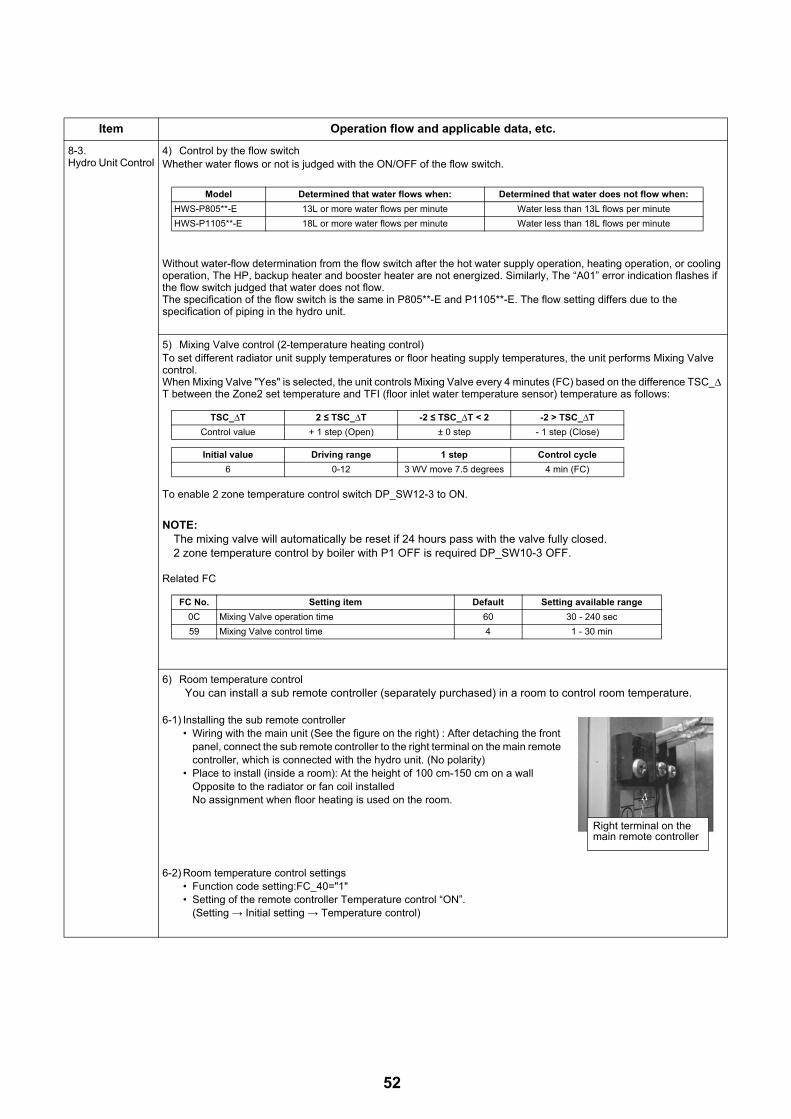
8-3.Hydro Unit Control
4) Control by the flow switchWhether water flows or not is judged with the ON/OFF of the flow switch.
Without water-flow determination from the flow switch after the hot water supply operation, heating operation, or cooling operation, The HP, backup heater and booster heater are not energized. Similarly, The “A01” error indication flashes if the flow switch judged that water does not flow.The specification of the flow switch is the same in P805**-E and P1105**-E. The flow setting differs due to the specification of piping in the hydro unit.
5) Mixing Valve control (2-temperature heating control)To set different radiator unit supply temperatures or floor heating supply temperatures, the unit performs Mixing Valve control.When Mixing Valve "Yes" is selected, the unit controls Mixing Valve every 4 minutes (FC) based on the difference TSC_Δ T between the Zone2 set temperature and TFI (floor inlet water temperature sensor) temperature as follows:
To enable 2 zone temperature control switch DP_SW12-3 to ON.
NOTE:The mixing valve will automatically be reset if 24 hours pass with the valve fully closed.2 zone temperature control by boiler with P1 OFF is required DP_SW10-3 OFF.
Related FC
6) Room temperature controlYou can install a sub remote controller (separately purchased) in a room to control room temperature.
6-1) Installing the sub remote controller• Wiring with the main unit (See the figure on the right) : After detaching the front
panel, connect the sub remote controller to the right terminal on the main remote controller, which is connected with the hydro unit. (No polarity)
• Place to install (inside a room): At the height of 100 cm-150 cm on a wall Opposite to the radiator or fan coil installedNo assignment when floor heating is used on the room.
6-2) Room temperature control settings• Function code setting:FC_40="1"• Setting of the remote controller Temperature control “ON”.
(Setting → Initial setting → Temperature control)
Item Operation flow and applicable data, etc.
Model Determined that water flows when: Determined that water does not flow when:
HWS-P805**-E 13L or more water flows per minute Water less than 13L flows per minute
HWS-P1105**-E 18L or more water flows per minute Water less than 18L flows per minute
TSC_ΔT 2 ≤ TSC_ΔT -2 ≤ TSC_ΔT < 2 -2 > TSC_ΔT
Control value + 1 step (Open) ± 0 step - 1 step (Close)
Initial value Driving range 1 step Control cycle
6 0-12 3 WV move 7.5 degrees 4 min (FC)
FC No. Setting item Default Setting available range
0C Mixing Valve operation time 60 30 - 240 sec
59 Mixing Valve control time 4 1 - 30 min
Right terminal on the main remote controller
52

8-3.Hydro Unit Control
6-3) Control method• The water temperature setting at starting operation is 40 °C (FC_9D) at heating and 20 °C (FC_96) at cooling.
If the temperature setting calculated by Auto curve at starting operation will be used instead of the fixed temperature 40 °C (FC_9D), FC_B5 should be set to “1”.
• The target water outlet temperature is adjusted by 1deg every 30 minutes based on the TSC_rc, the temperature setting on the remote controller, and the room temperature (temperature indicated on the remote controller: T_rc). The adjustable range of water temperature is set with FC18-1B.
• The temperature set on the remote controller and actual room temperature may differ depending on the place of the remote controller or room space. In that case, adjust temperature detection using FC02 (for heating) and FC03 (for cooling) on the remote controller.
How to shift up/down the temperature by remote controller FC02, 03• Ambient temperature (remote controller) is higher than room temperature: example. 1deg
Change remote controller FC02, 03 = “-1K” to “-2K”• Ambient temperature (remote controller) is lower than room temperature: example. 1deg
Change remote controller FC02, 03 = “-1K” to “0”
Related FC
Item Operation flow and applicable data, etc.
TSC_rc+2K
TSC_rc+1K
TSC_rc
TSC_rc-0.5K
Warm-mode
TSC_rc+0.5K
TSC_rc
TSC_rc+0K
TSC_rc-1.0K
Cool-mode
A zone:Thermo off
A’ zone:Thermo off
B zone:Down water temp
A zone:Thermo off
B zone:Up water tempC zone:Keep water temp
D zone:Up water temp
C zone:Keep water temp
D zone:Down water temp
T_rcCorrection controlHeating Cooling
D zoneSetting is corrected upwardWater temperature setting is up by 1deg every 30 minutes.
Setting is corrected upwardWater temperature setting is down by 1deg every 30 minutes.
C zone No correction No correction
B zoneSetting is corrected downward.Water temperature setting is down by 1deg every 30 minutes.
Setting is corrected downward.Water temperature setting is down by 1deg every 30 minutes.
A zoneThermo off. But if inlet water detect less 25 °C, then heat pump restart.
Thermo off
A’ zone
Setting is corrected downward.Water temperature setting is down by 1deg every 39 minutes.Thermo off
FC No. Setting item Default Variable range18 Upper limit of cooling temperature setting 25 18-25 °C19 Lower limit of cooling temperature setting 7 7-18 °C1A Upper limit of heating temperature setting (Zone 1) 60 37-60 °C1B Lower limit of heating temperature setting (Zone 1) 20 20-37 °C40 Room temperature control 0 0:Not permitted 1:Permitted
96Initial water temperature setting when controlling cooling by the room temperature remote controller and room temperature thermostat
20 10-25 °C
9DInitial water temperature setting when controlling heating by the room temperature remote controller and room temperature thermostat
40 20-60 °C
02 (Remote controller) Room temperature correction (at heating) -1 -10K - +10K, 1K step03 (Remote controller) Room temperature correction (at cooling) -1 -10K - +10K, 1K step
B2 Heat pump restart water condition in A zone. 25 20-37 °C
B5
Choose of the initial setting temperature.Either use the temperature set in FC_9D, or use the temperature calculated by Auto curve.This applies heating operation only.
0
0 : Use the temperatureset in FC_9D
1 : Use the temperature calculated by Auto curve
53

8-3.Hydro Unit Control
7) Room temperature control with the thermostatYou can install a commercially available thermostat to control room temperature.
7-1) Installing the room temperature thermostat• TCB-PCM03E optional PC board is required. Connect its connection cable to CN211 port on the PC board of the
hydro unit.• Wiring to the main unit: connect the optional PC board TCB-PCM03E to the hydro unit after detaching the front
panel. Thermostat for heating : Connect TCB-PCM03E between the terminals (1) and (3).Thermostat for cooling : Connect TCB-PCM03E between the terminals (2) and (3).
• Place to install (inside a room): At the height of 120 cm-180 cm on a wallOpposite to the radiator or fan coil installedNo assignment when floor heating is used on the room.
7-2) Room temperature thermostat control setting • Setting of DPSW on the hydro unit
DP_SW02_4=“ON” (Default “OFF”)
7-3)Heating thermostat operationWhen the heating thermostat does not reach the assigned temperature (the circuit between (1) and (3) is closed), heating starts under the setting that water temperature for heating is 40 °C (FC_9D). If the heating thermostat has not reached the assigned temperature 30 minutes after heating had started, the water temperature setting is turned up 1 degree, and the same action will be repeated every 30 minutes until the thermostat reaches the assigned temperature. The backup heater and booster heater are controlled in the same way as in the normal HP operation.
When the heating thermostat reaches the assigned temperature (the circuit between (1) and (3) is open), the heat
pump shifts to the “thermostat off” operation. During the operation, the water temperature setting is turned down by 1 degree every 30 minutes. The backup heater and booster heater are tuned off as the heat pump shifts to the “thermostat off” operation.
7-4)Cooling thermostat operationWhen the cooling thermostat does not reach the assigned temperature (the circuit between (2) and (3) is open), cooling starts under the setting that water temperature fro cooling is 20 °C (FC_96). If the cooling thermostat has not reached the assigned temperature 30 minutes after cooling had started, the water temperature setting is turned down 1 degree, and the same action will be repeated every 30 minutes until the thermostat reaches the assigned temperature.
When the cooling thermostat reaches the assigned temperature (the circuit between (2) and (3) is closed), operation
shifts to the “thermostat off” operation. During the operation, the water temperature setting is turned up by 1 degree every 30 minutes.
Related FC
Item Operation flow and applicable data, etc.
PJ17
Terminal label
TCB-PCMO3E
CN210Red
CN211Black
Room thermostat Correction control Heating operation Cooling operation
CLOSESetting is corrected upward
Thermo onThe water temperature setting is turned up by 1 degree every 30 minutes.
Thermo offThe water temperature setting is turned up by 1 degree every 30 minutes.
OPENSetting is corrected downward.
Thermo offThe water temperature setting is turned down by 1 degree every 30 minutes.
Thermo onThe water temperature setting is turned down by 1 degree every 30 minutes.
FC No. Setting item Default Variable range
9DInitial water temperature setting when controlling heating by the room temperature remote controller and room temperature thermostat.
40 20-60 °C
96Initial water temperature setting when controlling cooling by the room temperature remote controller and room temperature thermostat.
20 10-25 °C
B5
Choose of the initial setting temperature.Either use the temperature set in FC_9D, or use the temperature calculated by Auto curve.This applies heating operation only.
0
0 : Use the temperatureset in FC_9D
1 : Use the temperature calculated by Auto curve
54
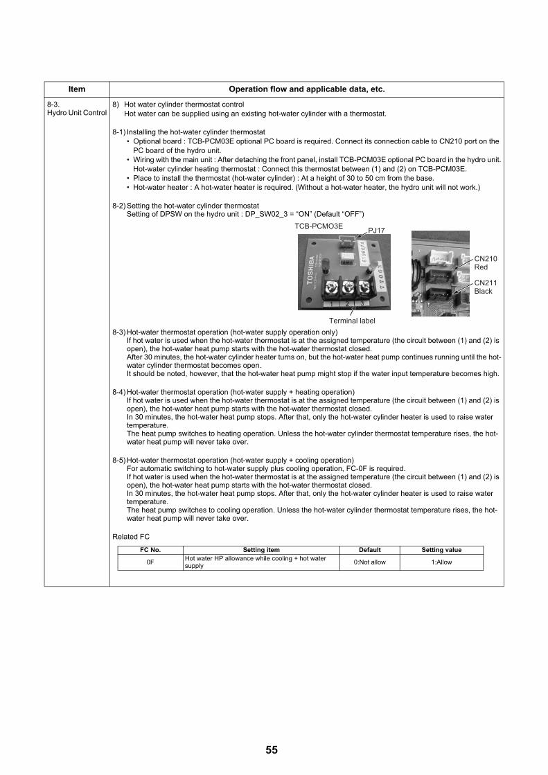
8-3.Hydro Unit Control
8) Hot water cylinder thermostat controlHot water can be supplied using an existing hot-water cylinder with a thermostat.
8-1) Installing the hot-water cylinder thermostat• Optional board : TCB-PCM03E optional PC board is required. Connect its connection cable to CN210 port on the
PC board of the hydro unit.• Wiring with the main unit : After detaching the front panel, install TCB-PCM03E optional PC board in the hydro unit.
Hot-water cylinder heating thermostat : Connect this thermostat between (1) and (2) on TCB-PCM03E.• Place to install the thermostat (hot-water cylinder) : At a height of 30 to 50 cm from the base.• Hot-water heater : A hot-water heater is required. (Without a hot-water heater, the hydro unit will not work.)
8-2) Setting the hot-water cylinder thermostatSetting of DPSW on the hydro unit : DP_SW02_3 = “ON” (Default “OFF”)
8-3) Hot-water thermostat operation (hot-water supply operation only)If hot water is used when the hot-water thermostat is at the assigned temperature (the circuit between (1) and (2) is open), the hot-water heat pump starts with the hot-water thermostat closed. After 30 minutes, the hot-water cylinder heater turns on, but the hot-water heat pump continues running until the hot-water cylinder thermostat becomes open. It should be noted, however, that the hot-water heat pump might stop if the water input temperature becomes high.
8-4) Hot-water thermostat operation (hot-water supply + heating operation)If hot water is used when the hot-water thermostat is at the assigned temperature (the circuit between (1) and (2) is open), the hot-water heat pump starts with the hot-water thermostat closed.In 30 minutes, the hot-water heat pump stops. After that, only the hot-water cylinder heater is used to raise water temperature. The heat pump switches to heating operation. Unless the hot-water cylinder thermostat temperature rises, the hot-water heat pump will never take over.
8-5) Hot-water thermostat operation (hot-water supply + cooling operation)For automatic switching to hot-water supply plus cooling operation, FC-0F is required. If hot water is used when the hot-water thermostat is at the assigned temperature (the circuit between (1) and (2) is open), the hot-water heat pump starts with the hot-water thermostat closed. In 30 minutes, the hot-water heat pump stops. After that, only the hot-water cylinder heater is used to raise water temperature. The heat pump switches to cooling operation. Unless the hot-water cylinder thermostat temperature rises, the hot-water heat pump will never take over.
Related FC
Item Operation flow and applicable data, etc.
PJ17
Terminal label
TCB-PCMO3E
CN210Red
CN211Black
FC No. Setting item Default Setting value
0FHot water HP allowance while cooling + hot water supply
0:Not allow 1:Allow
55

8-3.Hydro Unit Control
9) Control of force stop and restartThe unit can be stopped and restarted with external input. By setting FC52, FC61 and FCB6, you can set an operation mode to run/stop or can run/stop the unit in the mode assigned on the remote controller.
• TCB-PCM03E optional PC board is required. Connect its connection cable to CN210 port on the PC board of the hydro unit.
9-1)Setting the control methodSelect a control method by setting FC52.• FC52=“0”:Stops ESTIA as the circuit between the terminals (1) and (3) is closed. (Default)• FC52=“1”:Stops ESTIA as the circuit between the terminals (1) and (3) is opened.• FC52=“2”: Starts ESTIA as the circuit between the terminals (1) and (3) is closed.
Stops ESTIA as the circuit between the terminals (1) and (3) is opened.• FC52=“3”:Starts/Stops ESTIA as the circuit between the terminals (1) and (3) is received closed plus.
9-2)Setting the object to controlSelect an operation mode by setting FC61.• FC61=“0”:Hot water supply and heating (Default)• FC61=“1”:Follows the setting on the remote controller (If the hot water supply operation, heating operation, or hot
water supply + heating operation is started manually after the unit was stopped with an external input, the new status is reflected to the setting on the remote controller.)
• FC61=“2”:Hot water supply only• FC61=“3”:Heating only
It is possible to control each of the heating and hot water supply with the following settings:• FCB6=“1” (Default “0”) and FC61=“3” and DP_SW02_3=“OFF” (Default “OFF”)
The terminals (1) and (3) is the heating control.The terminals (2) and (3) is the hot water supply control. Both of control method is selected by FC52.
9-3)CautionsThe circuit between the external input terminals (1) and (3) is also used to control the limit of heat pump operation.You cannot use the forced stop control when the circuit is configured to control the limit of heat pump operation. (See page 58)
9-4)Setting example• When you want to turn on/off the unit with static external input reflecting the operation setting on the remote controller
(hot water supply, heating, or hot water supply and heating).FC52=“2”, FC61=“1”
Item Operation flow and applicable data, etc.
PJ17
Terminal label
TCB-PCMO3E
CN210Red
CN211Black
RC on condition× RC off condition
Operation Heating × ×status 1 Hot water × ×
open signal input
Operation Heatingstatus 2 Hot water
close signal input close signal input
Operation Heating × ×status 3 Hot water ×
× × × ×× × × ×
× × × ×× × × ×
×
open signal input
Operation Heatingstatus 4 Hot water
Operation patternFC61=1 & FC52=2
Manually ON/OFF change by remote controller
↓
↓
↓
56

8-3.Hydro Unit Control
Basic operation logicThere are 4 operation combination pattern for Heating & Hot water When open signal is input, the operation status change to the next status.For example, if current operation status is heating ON and hot water OFF, then next status to be heating OFF & hot water OFF when pulse is input Hydro unit memorize the status of the operation pattern before changing OFF status by close signal.If pulse is input at operation status 2, the operation pattern in the status 3 is same pattern in the status 1.
Manually ON/OFFIf customer change operation pattern manually by remote controller, change then operation pattern will not be same as the basic logic.1. If customer stop operation (Heating off and hot water off) by the controller, then both heating& hot water
are not to be ON with close or open signal.2. If the unit is stopped (Heating off and hot water off) by open signal, operation pattern will be referred to
the pattern before the unit OFF by close signal.
• When you want to turn on/off with the pulse input reflecting the operation setting on the remote controller (hot water supply, heating, or hot water supply and heating).FC52=“3”, FC61=“1”
There are 4 operation combination pattern for Heating & Hot water When pulse signal is input, the operation status change to the next status.For example, if current operation status is heating ON and hot water OFF, then next status to be heating OFF & hot water OFF when pulse is input Hydro unit memorize the status of the operation pattern before changing OFF status by pulse signal.If pulse is input at operation status 2, the operation pattern in the status 3 is same pattern in the status 1.
If customer change operation pattern manually by remote controller, then operation pattern will not be same as the basic logic.1. If customer stop operation (Heating off and hot water off) by the controller, then both heating& hot water
to be ON with pulse input.2. If the unit is stopped (Heating off and hot water off) by pulse input, operation pattern will be referred to
the pattern before the unit OFF by pulse.
Related FC
Item Operation flow and applicable data, etc.
RC on condition× RC off condition
Operation Heating × ×status 1 Hot water × ×
Pulse input
Operation Heating × × ×
× ×
status 2 Hot water × × ×
Pulse inputPulse input
Operation Heatingstatus 3 Hot water × ×
Pulse input
Operation Heating × × ×status 4 Hot water × × ×
FC61=1 & FC52=3Operation pattern
Manually ON/OFFchange by remotecontroller
↓
↓
↓
FC No. Setting item Default Setting value
52 Control method 0 See page 121
61 Object to control 0 See page 121
57

58
8-3.Hydro Unit Control
10) Control of limit of heat pump operationWhen the peak period of electric power charge is set due to the contract or other conditions, you can limit heat pump operation and give priority to boiler operation using an external input signal. (This control functions only during the period the signal is input.)
• TCB-PCM03E optional board is required. Connect its connection cable to CN210 port on the PC board of the hydro unit.
10-1)Setting the control methodSelect an operation mode by setting FC61.• FC61=“4”:Hot water cylinder heater = OFF, backup heater = OFF (Built-in circulation pump is ON.)• FC61=“5”:Hot water cylinder heater = OFF, backup heater = OFF, heat pump = OFF, Built-in circulation pump is
stopped.
10-2)Control summaryWhen the TEMPO signal is input (the circuit is closed), the boiler signal is output regardless the outside temperature and devices are turned off following the setting on FC61.
1. Basic operation: heating operation using the boiler2. Switching to hot water supply: the water circuit is switched to the hot water supply side as the unit detect
that TTW is less than 38 °C.3. Switching to heating: the water circuit is switched to the heating side as the unit detect that TTW is 45 °C
or more, or 30 minutes has passed since operation started. Heating operation continues at least 30 minutes.
4. The LED on the PC board lights up when the input signal is ON.
11)Output signal control 1(TCB-PCIN3E optional PC board is required. Connect its connection cable to the CN208 terminal on the PC board in the hydro unit.)• The circuit between the terminals (1) and (2) gets closed as an error detection signal is output.• The circuit between the terminals (3) and (4) gets closed as a boiler signal is output.
The LED on the PC board lights up when the signals are output.
12)Output signal control 2(TCB-PCIN3E optional PC board is required. Connect its connection cable to the CN209 terminal on the PC board in the hydro unit.)< FC67=“0”: Default >• The circuit between the terminals (1) and (2)
is closed during defrosting.• The circuit between the terminal (3) and (4)
is closed while the compressor is running.
< FC67=“1” >• The circuit between the terminals (1) and (2)
gets closed as an error is detected.• The circuit between the terminals (3) and (4)
is closed during operation (when the remote controller is ON)The LED on the PC board lights up when the signals are output.
Related FC
Item Operation flow and applicable data, etc.
PJ17
Terminal label
TCB-PCMO3E
CN210Red
CN211Black
PJ20
Terminal label
TCB-PCIN3E CN208 Blue
CN209Green
FC No. Setting item Default Setting value
67Changing the condition of optional output (For the optional PC board connected to CN209)
0: 1-2 During defrosting
2-4 While compressor is running.
1: 1-2 As error is detected
2-4 During operation

8-3.Hydro Unit Control
13) Q-H characteristics of hydro unitThe following shows the Q-H characteristics.
13-1)HWS-P805XWHM3-E, T6-E, T9-E
13-2)HWS-P1105XWHM3-E, T6-E, T9-E
Item Operation flow and applicable data, etc.
Flow rate [L/min]
Hea
d [m
]
Minimum flow rate
Hydraulic heat exchanger (8 kW) QH characteristics
0 5 10 15 20 25 30 350
1
2
3
4
5
6
7
8
9
10
Pump duty80 %
Pump duty 100 %
Pump duty60 %
Hydro unit QH-Characteristics (220/230 V)
Out of range
Minimum flow rate
Hydraulic heat exchanger (11 kW) QH characteristics
Hea
d [m
]
0
1
2
3
4
5
6
7
8
9
10
0 10 20 30 40 50
Flow rate [L/min]
Pump duty 100 %
Pump duty80 %
Pump duty60 %
Hydro unit QH-Characteristics (220/230 V)
Out of range
59

8-3.Hydro Unit Control
14) Automatic restart controlThe unit records operation information before a power outage and retrieves the information after the power is restored to restart automatically the operation with the information.
14-1)Operation during remote controller• The operation status before a power outage automatically restarts after the power is restored. (The merit functions
are also enabled)• Approximately 6 hours or more after a power outage
The operation status before a power outage automatically restarts after the power is restored.But the merit functions (Night setback, Anti bacteria) are disabled.
• The remote controller time displays "00:00". (The merit functions are disabled)
14-2)Operation during forcible automatic operationA forcible automatic operation is performed when the power is restored after a power outage.
14-3) Operation during defrosting operationWhen the power is restored after a power outage, the usual operation restarts.Note: The operation details recorded before a power outage
Operation mode: Hot water supply, Heating, Cooling, Hot water supply + Heating, Hot water supply + CoolingSet temperature: Hot water set temperature, Heating set temperature, Cooling set temperature
Merit function: Hot water supply operation (Anti bacteria)Heating operation (Night setback)
15) Piping freeze prevention controlThis control operates when the power is on regardless the remote controller setting ON or OFF.To prevent frost bursting of the water piping for hot water supply and heating, the unit flows water with the circulation pump when the temperature sensor value falls below a certain temperature.
15-1)Piping freeze prevention control 11) Start condition: TWO < 4 °C or THWI < 4 °C.or THO < 4 °C2) End condition: TWO ≥ 5 °C and TWI ≥ 5 °C and THO ≥ 5 °C3)-1 How to operate (circulation pump)
• When the circulation pump is not in operation, if the sensor detects the freeze prevention control start temperature, the unit operate the circulation pump.
• During a freeze prevention operation, a heat pump operation does not start.• When neither [Hot water supply] nor [heating/cooling] is in operation, if the end condition is not met when 3
minutes has passed after an operation starts, the unit performs the operation in 3)-2 to prevent freeze.3)-2 How to operate (circulation pump + backup heater)
• When neither [Hot water supply] nor [heating/cooling] is in operation, if the end condition is not met when 3 minutes has passed after an operation starts.
• End condition: TWO ≥ 5 °C and TWI ≥ 5 °C and THO ≥ 5 °C• Heating with the set temperature 55 °C operates.
3)-3 Abnormal stop• If a freeze prevention operation continues for 30 minutes and does not meet the end condition, the operation
stops as abnormal stop. (Remote controller check code: A05)
15-2)Piping freeze prevention control 2TC and TWO activates freeze prevention regardless of a heat pump operation mode.1) Determination condition: TWO>20 °C. 2*TC+TWO<-12 °C is continuously detected for 180 seconds or longer.
Or TWO ≤ 20 °C. TC+TWO<4 °C is continuously detected for 180 seconds or longer.2) Determination cancellation conditions
• The stop or operation mode is changed by the remote controller• The mode is defrosting at the time of determination
At the next time of defrosting, the start condition is not met.• The mode is other than defrosting at the time of determination
After cooling, heating, hot water heat pump restarts, the start condition is not met for 10 minutes.3) Error display
• If freeze determination cancellation condition is not met, A04 error is displayed.
15-3)Piping freeze prevention control 3This control applies only when defrosting is in operation.1) Determination condition: During defrosting, TWI ≤ 15 °C is continuously detected for 30 seconds or longer (After
the stop, the unit restarts.)2) Determination cancellation condition
• At the next time of defrosting, the start condition is not met.3) Error display
• If freeze determination cancellation condition is not met, A04 error is displayed.
Item Operation flow and applicable data, etc.
60
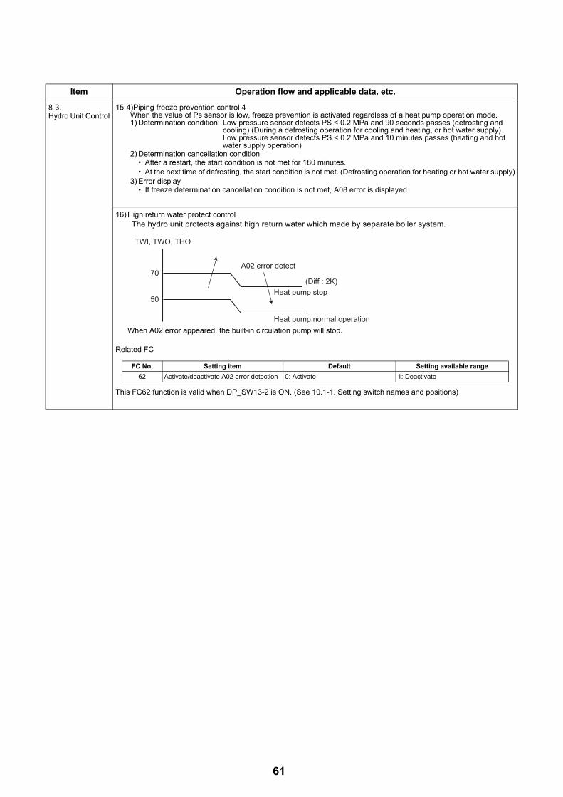
8-3.Hydro Unit Control
15-4)Piping freeze prevention control 4When the value of Ps sensor is low, freeze prevention is activated regardless of a heat pump operation mode.1) Determination condition: Low pressure sensor detects PS < 0.2 MPa and 90 seconds passes (defrosting and
cooling) (During a defrosting operation for cooling and heating, or hot water supply)Low pressure sensor detects PS < 0.2 MPa and 10 minutes passes (heating and hot water supply operation)
2) Determination cancellation condition• After a restart, the start condition is not met for 180 minutes.• At the next time of defrosting, the start condition is not met. (Defrosting operation for heating or hot water supply)
3) Error display• If freeze determination cancellation condition is not met, A08 error is displayed.
16) High return water protect controlThe hydro unit protects against high return water which made by separate boiler system.
When A02 error appeared, the built-in circulation pump will stop.
Related FC
This FC62 function is valid when DP_SW13-2 is ON. (See 10.1-1. Setting switch names and positions)
Item Operation flow and applicable data, etc.
70
TWI, TWO, THO
(Diff : 2K)
A02 error detect
Heat pump normal operation
Heat pump stop50
FC No. Setting item Default Setting available range
62 Activate/deactivate A02 error detection 0: Activate 1: Deactivate
61

8-4.Outdoor unit control
1) PMV (Pulse motor valve) controlValve opening is controlled using the expansion valve with a pulse motor according to a heat pump operation status.
• PMV is controlled between 30 and 500 pulses during an operation.• At the time of a cooling operation, PMV is controlled with the usual target value of 1 to 4 K temperature difference
between TS sensor and TC sensor.• At the time of a hot water supply or heating operation, PMV is controlled with the usual target value of -1 to 4 K (for
P805HR-E, P1105HR-E) temperature difference between TS sensor and TE sensor.• For both cooling and heating, if the cycle is overheated, PMV is controlled using the TD sensor. The usual target
value is 91 °C for a cooling operation, and 96 °C for a heating operation.* A defective sensor may cause liquid back flow or abnormal overheat of the compressor, significantly shortening the
compressor life. If the compressor or other equipment is repaired, first check that the resistance of each sensor or the refrigerant cycle has no problem, then start the operation.
2) Discharge temperature release controlThis control detects an abnormality of the refrigerant cycle or compressor to perform failure prevention.
• This control reduces operation frequency if the PMV control does not lower the outlet temperature or if the outlet temperature rapidly rises. The frequency control is broken down to the unit of 0.6 Hz to stabilize the cycle.
• If the discharge temperature detects the abnormal stop zone, the compressor stops and then restarts after 150 seconds. The abnormality detection counter is cleared when the operation continues for 10 minutes. If detected 4 times, the error code is displayed and the compressor does not restart.
* An abnormality could occur due to too less refrigerant, PMV defective, or cycle stuck.• For details about an error displayed, see the check code list.
Item Operation flow and applicable data, etc.
TD [°C]
111
109
106
103
96
Abnormal stop
Frequency normal down
Frequency slow down
Frequency hold
Frequency slow up (up to the point instructed)
As instructed
62

8-4.Outdoor unit control
3) Current release controlThe number of compressor rotation is controlled so that current value of the compressor drive circuit does not exceed the specified value.
• The outdoor unit detects the input current.• The outside air temperature is detected and used to set the specified value of current. • The number of compressor rotation instructed by the hydro unit is used to determine whether the current value
exceeds the specified value.• If exceeds, the number of compressor rotation is reduced to the most approximate number instructed by the hydro
unit within the specified value range.
Heating, Hot water supply
Cooling
No cooling operation available for TO < 10 °C.
Item Operation flow and applicable data, etc.
Outdoor unit current inverterMain circuit control current
Compressor operation Hz down
Outside air temperature (TO)
Current release point setting
Capacity control continue
Operation current ≤ Settings
Current degradation
Yes
No
Outside temperatureTO (degree °C)
Current release value (A)
P805HR-E, P1105HR-E
27.5 ≤ TO 15.0
15 ≤ TO < 27.5 20.0 - (To - 15) × 0.4
TO < 15 20.0
Outside temperatureTO (degree °C)
Current release value (A)
P805HR-E, P1105HR-E
44 ≤ TO 15.0
39 ≤ TO < 44 17.7
10 ≤ TO < 39 20.0
15.0
20.0CT(A)
15 27.5 TO
Heating, Hot water supply
17.715.0
20.0CT(A)
10 39 44 TO
Cooling
63

8-4.Outdoor unit control
4) Current releases shift controlDuring a cooling operation, this control prevents the electronic parts, such as a compressor drive element, and compressor from failing.
• The current release control value (I) is selected from the following table according to the TO sensor value.
Current release control value (I)
5) Outdoor fan controlThe outdoor side control part controls the number of fan motor rotations by receiving an operation instruction from the Hydro side (Hydro unit) control part.For sensing the true outside temperature, fan is operated without compressor operation.* Although the fan motor is a DC motor, which has non-step variable numbers of rotations, it is limited to some steps for convenience of
control.
The number of fan tap rotation allocation [rpm]
5-1) Cooling fan control• The TL sensor, TO sensor and operation frequency control the outdoor fan. The control is performed by 1 tap of
the DC fan control (14 taps).• For 60 seconds after the start, the maximum fan tap for each zone that is shown in the following table is fixed. After
that, the fan is controlled according to the TG. (TG: temperature converted from PD)
HWS-P805HR-E, P1105HR-E
Item Operation flow and applicable data, etc.
Temperature range P805HR-E, P1105HR-E
50 °C ≤ TO 14.1
45 °C ≤ TO < 50 °C 14.1
39 °C ≤ TO < 45 °C 14.1
TO < 39 °C 14.1
TO error 14.1
W1 W2 W3 W4 W5 W6 W7 W8
P805HR-E, P1105HR-E
Upper 200 240 240 260 320 380 480 500
Lower 0 0 200 280 360 400 500 520
W9 WA WB WC WD WE WF
P805HR-E, P1105HR-E
Upper 530 610 640 660 720 780 890
Lower 550 630 660 700 740 820 910
TG [°C]
58
55
3835
WE tap
+ 1 tap/20 secs (Up to the maximum number of rotation for each zone)
- 1 tap/20 secs (Up to the minimum number of rotation for each zone)
Number of rotation hold
Temperature rangeLess than 20 Hz 20 Hz or more to less
than 45 Hz 45 Hz or more
Minimum Maximum Minimum Maximum Minimum Maximum
38 °C ≤ TO W6 WC W8 WC WA WD
29 °C ≤ TO < 38 °C W5 WB W7 WB W9 WC
15 °C ≤ TO < 29 °C W4 W8 W6 WA W8 WC
5 °C ≤ TO < 15 °C W3 W6 W5 W8 W7 WA
0 °C ≤ TO < 5 °C W2 W4 W4 W6 W5 W8
-4 °C ≤ TO < 0 °C W2 W3 W3 W5 W4 W6
TO < -4 °C W1 W2 W1 W4 W2 W6
TO error W1 WC W1 WC W2 WD
64

8-4.Outdoor unit control
5-2) Hot water supply and heating fan control
1) The TE sensor, TO sensor and operation frequency control the outdoor fan. (The minimum W1 to the maximum are controlled according to the table below.)
2) For 3 minutes after the start, the maximum fan tap for each zone that is shown in the following table is fixed. After that, the fan is controlled according to the TE sensor temperature.
3) If TE ≥ 24 °C continues for 5 minutes, the operation stops. No error code is displayed for this; the status is the same as the usual thermostat off. The operation restarts after 150 seconds. This intermittent running is not abnormal.
NOTE
If the heat-pump was thermo-off, the out-door fan motor (up/down) continue to run 10 min with W3 rotation. When the water pump of hydro unit turns on, the fan motor will operate sensing value of outside air temperature (TO).
Item Operation flow and applicable data, etc.
TE [°C]
24
21
18
15
-1 tap/20 secs (to W1)
-2 tap/20 secs (to W1)
-2 tap/20 secs (to W1)Stop time count
Number of revolutions hold
+ 1 tap/20 secs (Up to the maximum tap for each zone)
Temperature rangeLess than 20 Hz 20 Hz or more to less
than 45 Hz 45 Hz or more
Maximum Maximum Maximum
30 °C ≤ TO W4 W4 W6
25 °C ≤ TO < 30 °C W5 W5 W7
20 °C ≤ TO < 25 °C W6 W7 W8
10 °C ≤ TO < 20 °C W7 W8 W9
5 °C ≤ TO < 10 °C W9 WA WA
-3 °C ≤ TO < 5 °C WA WA WB
-10 °C ≤ TO < -3 °C WB WB WB
TO < -10 °C WD WD WD
TO abnormal WD WD WD
65
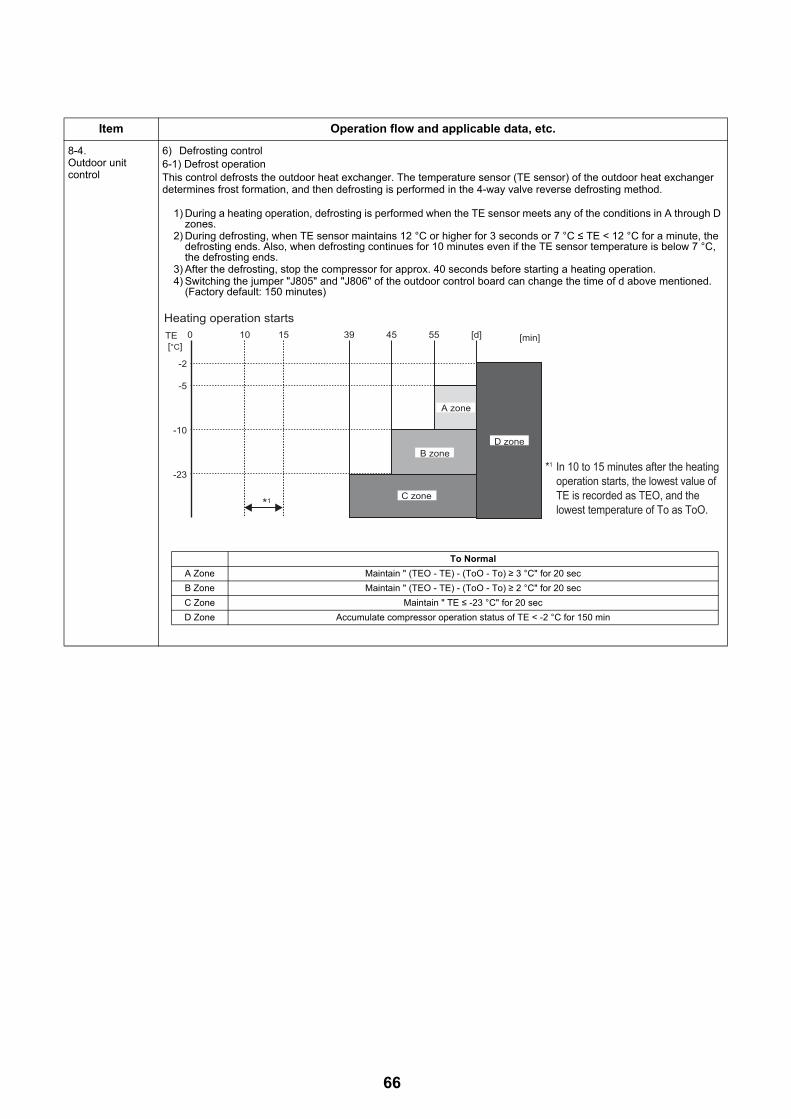
8-4.Outdoor unit control
6) Defrosting control6-1) Defrost operationThis control defrosts the outdoor heat exchanger. The temperature sensor (TE sensor) of the outdoor heat exchanger determines frost formation, and then defrosting is performed in the 4-way valve reverse defrosting method.
1) During a heating operation, defrosting is performed when the TE sensor meets any of the conditions in A through D zones.
2) During defrosting, when TE sensor maintains 12 °C or higher for 3 seconds or 7 °C ≤ TE < 12 °C for a minute, the defrosting ends. Also, when defrosting continues for 10 minutes even if the TE sensor temperature is below 7 °C, the defrosting ends.
3) After the defrosting, stop the compressor for approx. 40 seconds before starting a heating operation.4) Switching the jumper "J805" and "J806" of the outdoor control board can change the time of d above mentioned.
(Factory default: 150 minutes)
Item Operation flow and applicable data, etc.
Heating operation starts
-2
-5
-10
-23
TE [°C]
0 10 15 39 45 55 [d] [min]
D zone
A zone
B zone
C zone*1
*1 In 10 to 15 minutes after the heating operation starts, the lowest value of TE is recorded as TEO, and the lowest temperature of To as ToO.
To Normal
A Zone Maintain " (TEO - TE) - (ToO - To) ≥ 3 °C" for 20 sec
B Zone Maintain " (TEO - TE) - (ToO - To) ≥ 2 °C" for 20 sec
C Zone Maintain " TE ≤ -23 °C" for 20 sec
D Zone Accumulate compressor operation status of TE < -2 °C for 150 min
66
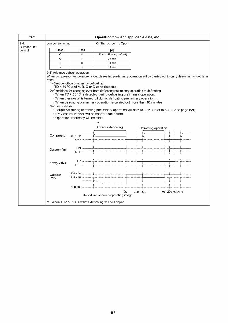
8-4.Outdoor unit control
Jumper switching O: Short circuit ×: Open
6-2) Advance defrost operationWhen compressor temperature is low, defrosting preliminary operation will be carried out to carry defrosting smoothly in effect.
1) Start condition of advance defrosting•TD < 50 ºC and A, B, C or D zone detected.
2) Conditions for changing over from defrosting preliminary operation to defrosting.• When TD ≥ 50 °C is detected during defrosting preliminary operation.• When thermostat is turned off during defrosting preliminary operation.• When defrosting preliminary operation is carried out more than 10 minutes.
3) Control details• Target SH during defrosting preliminary operation will be 6 to 10 K. (refer to 8-4-1 (See page 62))• PMV control interval will be shorter than normal.• Operation frequency will be fixed.
*1. When TD ≥ 50 °C, Advance defrosting will be skipped.
Item Operation flow and applicable data, etc.
J805 J806 [d]
O O 150 min (Factory default)
O × 90 min
× O 60 min
× × 30 min
Advance defrosting Defrosting operation
*1
Compressor
OFF40.1 Hz
Outdoor fanOFFON
4-way valveOFF
On
Outdoor PMV 430 pulse
500 pulse
0 pulse
Dotted line shows a operating image.0s 30s 40s 0s 20s30s 40s
67

8-4.Outdoor unit control
7) Winding heating control1) This control energizes the inactive compressor instead of the case heater to warm the compressor. The purpose is
to prevent the refrigerant from staying inside the compressor.2) After the unit is installed, failure to perform energization for the given time period may cause the compressor to fail.
Also, when starting an operation long after the power left off, first energize the compressor before starting the operation in the same way as a trial run.
3) Energization is determined by the TD sensor and TO sensor. If the TO sensor fails, the TE sensor automatically takes over the operation. Determine if the TO sensor has failed check the LED’s on the outdoor unit PCB.
4) If TD is 30 °C or higher, the energization stops.
NotesDuring winding energization, energizing noise may be heard, but this is not abnormal.
8) Short circuit operation prevention control1) In 11 minutes after the operation start, the compressor may not stop for protection. This status is not abnormal. (The
operation duration time of the compressor varies depending on a operation status.)2) If the operation stops with the remote controller, the operation does not continue.
9) Over current protection control1) A detection of abnormal current with the over current protection control stops the compressor.2) Set the abnormality detection counter to 1, and restarts the compressor after 150 seconds.3) When the stop by over current protection control counts 8 times, error code is displayed and the compressor does
not restart.(Remote controller error code display: HO1)
Item Operation flow and applicable data, etc.
(Usual)
18 °C
15 °C
10 °C
8 °C
TO
*Energization condition TD 30 °C
Not energized
Intermittently energized10 mins: ON / 5 mins: OFFOutput "equal to 40W"
Continuously energizedOutput "equal to 40W"
(when TO sensor fails)
20 °C
18 °C
12 °C
10 °C
TE
*Energization condition TD 30 °C
Not energized
Intermittently energized10 mins: ON / 5 mins: OFFOutput "equals to 40W"
Continuously energizedOutput "equals to 40W"
68

8-4.Outdoor unit control
10) High pressure release control1) To prevent excessive high pressure rise, operating frequency is controlled by the PD sensor.2) If the PD sensor detects an abnormal stop zone pressure, the compressor stops and the abnormality detection
counter increments.3) When the compressor stops in 2), the heat-pump operation restarts when the pressure decrease to zone "e" (normal
operation) after 150 seconds passed.4) When the compressor stops in 2), the abnormality detection counter is cleared when the operation continues for 10
minutes. If the counter counts 10 times, error code is displayed on the remote-controller and the compressor does not restart.
5) For details about an check code displayed, see the check code list. (See page 74)
11) Compressor case thermostat The compressor case thermostat functions to protect the compressor when the blow-out temperature from the compressor is too high.• The compressor case thermostat on the upper part of compressor stops the compressor.• The compressor will restart three minutes after stopping.• If the compressor case thermostat functions again after restarting (functions at 125 °C), compressor stops and the
“H04” error code is indicated.
12) Bottom plate heater controlControl ON and OFF of the bottom plate heater using the outdoor temperature sensor (TO).
Item Operation flow and applicable data, etc.
3.30
3.40
3.50
3.60
3.70
3.80
3.90
4.00
4.10
0 10 20 30 40 50 60 70 80 90
PD s
enso
r [M
Pa]
Compressor frequency [Hz]
a
b,c
d
eNormal operation
+2
TO
0Bottom plate heater is turned on
Bottom plate heater is turned off
69
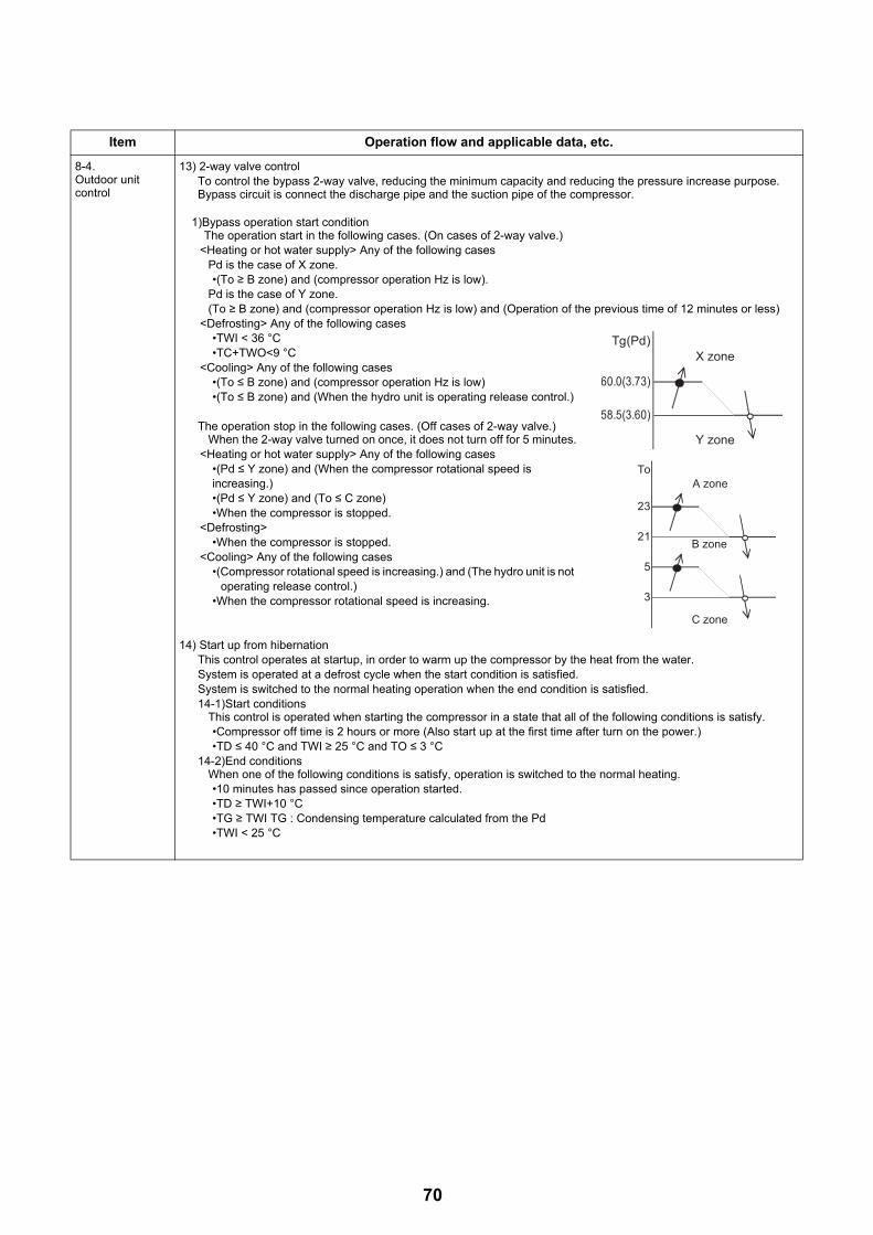
8-4.Outdoor unit control
13) 2-way valve controlTo control the bypass 2-way valve, reducing the minimum capacity and reducing the pressure increase purpose.Bypass circuit is connect the discharge pipe and the suction pipe of the compressor.
1)Bypass operation start conditionThe operation start in the following cases. (On cases of 2-way valve.)
<Heating or hot water supply> Any of the following casesPd is the case of X zone.•(To ≥ B zone) and (compressor operation Hz is low).
Pd is the case of Y zone.(To ≥ B zone) and (compressor operation Hz is low) and (Operation of the previous time of 12 minutes or less)
<Defrosting> Any of the following cases•TWI < 36 °C•TC+TWO<9 °C
<Cooling> Any of the following cases•(To ≤ B zone) and (compressor operation Hz is low)•(To ≤ B zone) and (When the hydro unit is operating release control.)
The operation stop in the following cases. (Off cases of 2-way valve.)When the 2-way valve turned on once, it does not turn off for 5 minutes.
<Heating or hot water supply> Any of the following cases•(Pd ≤ Y zone) and (When the compressor rotational speed is increasing.)•(Pd ≤ Y zone) and (To ≤ C zone)•When the compressor is stopped.
<Defrosting>•When the compressor is stopped.
<Cooling> Any of the following cases•(Compressor rotational speed is increasing.) and (The hydro unit is not
operating release control.)•When the compressor rotational speed is increasing.
14) Start up from hibernationThis control operates at startup, in order to warm up the compressor by the heat from the water.System is operated at a defrost cycle when the start condition is satisfied.System is switched to the normal heating operation when the end condition is satisfied.14-1)Start conditions
This control is operated when starting the compressor in a state that all of the following conditions is satisfy.•Compressor off time is 2 hours or more (Also start up at the first time after turn on the power.)•TD ≤ 40 °C and TWI ≥ 25 °C and TO ≤ 3 °C
14-2)End conditionsWhen one of the following conditions is satisfy, operation is switched to the normal heating.•10 minutes has passed since operation started.•TD ≥ TWI+10 °C•TG ≥ TWI TG : Condensing temperature calculated from the Pd•TWI < 25 °C
Item Operation flow and applicable data, etc.
Tg(Pd)X zone
60.0(3.73)
58.5(3.60)
Y zone
To
3
5
B zone
23
21
C zone
A zone
70
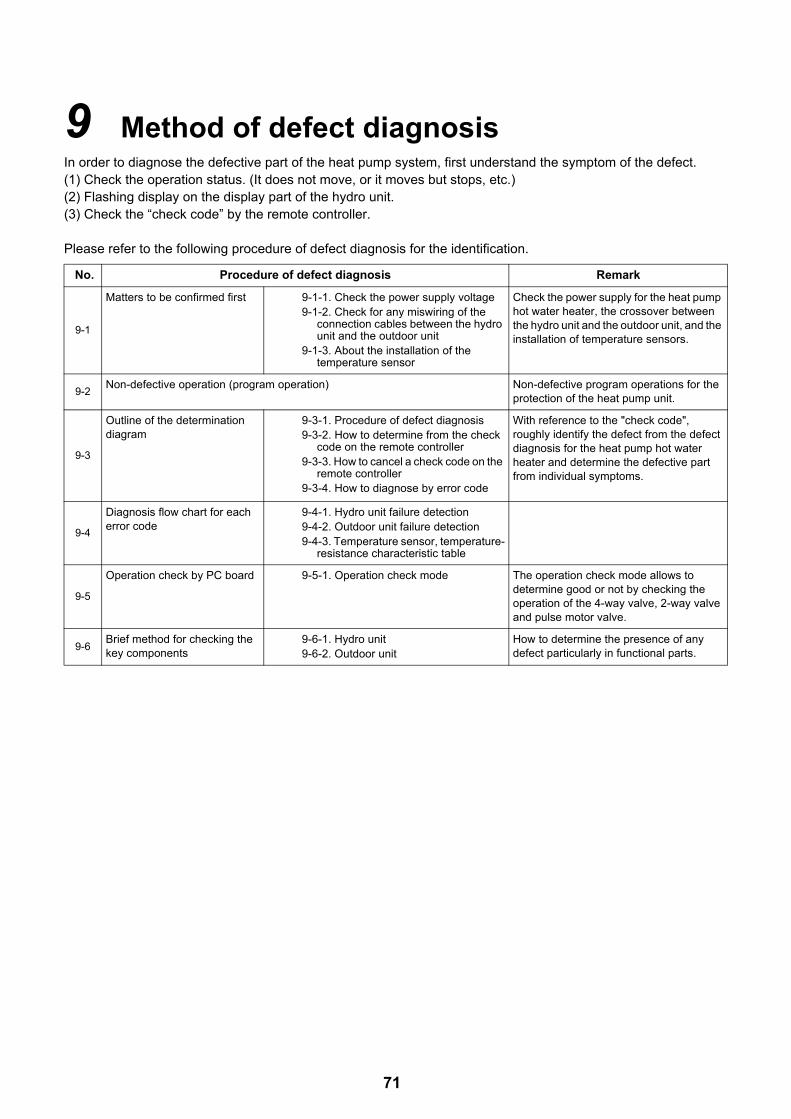
9 Method of defect diagnosis In order to diagnose the defective part of the heat pump system, first understand the symptom of the defect.(1) Check the operation status. (It does not move, or it moves but stops, etc.)(2) Flashing display on the display part of the hydro unit. (3) Check the “check code” by the remote controller.
Please refer to the following procedure of defect diagnosis for the identification.
No. Procedure of defect diagnosis Remark
9-1
Matters to be confirmed first 9-1-1. Check the power supply voltage9-1-2. Check for any miswiring of the
connection cables between the hydro unit and the outdoor unit
9-1-3. About the installation of the temperature sensor
Check the power supply for the heat pump hot water heater, the crossover between the hydro unit and the outdoor unit, and the installation of temperature sensors.
9-2Non-defective operation (program operation) Non-defective program operations for the
protection of the heat pump unit.
9-3
Outline of the determination diagram
9-3-1. Procedure of defect diagnosis9-3-2. How to determine from the check
code on the remote controller9-3-3. How to cancel a check code on the
remote controller9-3-4. How to diagnose by error code
With reference to the "check code", roughly identify the defect from the defect diagnosis for the heat pump hot water heater and determine the defective part from individual symptoms.
9-4
Diagnosis flow chart for each error code
9-4-1. Hydro unit failure detection9-4-2. Outdoor unit failure detection9-4-3. Temperature sensor, temperature-
resistance characteristic table
9-5
Operation check by PC board 9-5-1. Operation check mode The operation check mode allows to determine good or not by checking the operation of the 4-way valve, 2-way valve and pulse motor valve.
9-6Brief method for checking the key components
9-6-1. Hydro unit9-6-2. Outdoor unit
How to determine the presence of any defect particularly in functional parts.
71

9-1. Matters to be confirmed first9-1-1. Check the power supply voltageCheck that the power supply voltage is AC220-230 V± 10% (signal phase). If the power supply voltage is not in this range, it may not operate normally.
9-1-2. Check for any miswiring of the connection cables between the hydro unit and the outdoor unit
The hydro unit and the outdoor unit are connected with three connection cables. Make sure the interconnecting connections between the hydro unit and the outdoor unit terminal blocks are connected to the correct terminal numbers. If not connected correctly, the heat pump system does not operate. However, a miswiring would not cause damage to the equipment.
9-1-3. About the installation of the temperature sensorIf each sensor is removed due to the replacement of the water heat exchange or inverter board, or the replacement of the refrigeration cycle parts, make sure to put the sensor back to the position where it was before. • Each sensor position has a marking. Make sure to put it back to the exact position. • Make sure to install it with a sensor holder so that the temperature sensing part of the sensor and the straight
part of the copper piping are attached with each other tightly. • If the installation of the sensor is incomplete or the installed position is wrong, it will not perform a normal control
operation and may cause a defect such as a malfunction of the equipment or an occurrence of an abnormal sound, etc.
9-2. Non-defective operation (program operation) … No fault code display appears.
In order to control the heat pump unit, there are the following operations as the built-in program operations in the microcomputer. If a claim occurs about the operation, please confirm whether it falls under any of the contents in the following table. If it does, please understand that the symptom is not a defect of the equipment, and it is an operation necessary for the control and maintenance of the heat pump unit.
Table 9-2-1 Non-defective operation
No. Operation of the heat pump system Explanation
1The compressor sometimes does not operate even within the range of compressor “ON”.
The compressor does not operate during the operation of the compressor reboot timer (3 min). Even after the power activation, the compressor reboot timer continues to be active.
2
During the hot water supply or heating operation, without reaching the set temperature, the compressor operation frequency stays at a frequency of less than the maximum Hz or lowers down.
It may be caused by the high temperature release control (release protection control by the temperature of the water heat exchanger) or the current release control, or the high pressure release control.
3The “Stop” operation on the remote controller will not stop the circulation pump. (The same for hot water supply, heating and cooling)
In order to deal with the temperature increase in the heat exchanger after stopping, the operation continues for 1 min after the compressor is stopped.
4
“ON” on the remote controller will not operate the compressor. (It will not operate even after the reboot delay timer elapsed)
When the outdoor temperature (TO sensor detection temperature) is -25 °C or lower, the heat pump will not operate in order to protect the compressor, and the heater will operate instead.
5
When the power is turned on, it starts operation without operating the remote controller.
• The auto restart operation may be working.• The antifreeze operation may be working. • If the TWI, TWO or THO sensor detects a temperature
below 4 °C, the operation changes from circulation pump --->> circulation pump + heater.)
72

73
9-3. Outline of the determination diagramThe first determination of whether a defective part is in the hydro unit or the outdoor unit can be performed by the following method.
9-3-1. Procedure of defect diagnosisIn the case of a defect, please apply the following procedure in order to find the defective part.
9-3-2. How to determine from the check code on the remote controller
If the defect is limited by the check code displayed on the remote controller, please repair the defect based on the table on the next page. The check codes are separated into two groups: software and hardware errors. Since a hardware error cannot be cancelled without a part replacement etc., please perform a repair. If its abnormality is determined, the abnormality is noticed by indicating the check code on the remote controller check code display part while sounding off a buzzer.
9-3-3. How to cancel a check code on the remote controllerPress [ ] or [ ] button (on the operation side) to clear the check code.
Although the above procedure cancels the check code, the hardware error will be displayed again until the hardware repair is completed.
Defect Yes
Yes
Yes
No
No
No
Confirm the check code on the remote controller display
Check codeA01-A13
Check codeL07-L16
Check codeFXX
Defect in Hydro unit
Abnormality in the communication or setting system
Abnormality in the water heat exchange or outdoor unit sensor system
Abnormality in the outdoor unit or hot-water tank unit
ZONE1 ZONE2 HOT WATER
HEAT/COOL HOT WATER
MON
Check code display part

9-3-4. How to diagnose by error code
Defect mode detected by the Hydro UnitO ... Possible× .... Not possible
Check code
Diagnostic functional operation
Determination and action
Number of abnormalities
for confirmation
Detailed itemOperational cause Backup
operationAutomatic
reset
A01
Pump or flowing quantity error
1) Detected by TC sensorTC≥63 °C is detected in the heating or hot water supply heat pump operation (except for defrosting).
Heating
×Hot water
O
×
1. Almost no or little water flow. • Not enough vent air• Dirt clogging in the water piping
system. • The water piping is too long. • Installation of buffer tank and
secondary pump
4 82
2)Detected by flow switch abnormality
When no signal of the flow switch is showing 2 min after the built-in circulation pump operation started.
8 82
3)Detection of chattering abnormality in the flow switch input
Chattering detection: Detects input changes (OFF⇔ON) 4 times within 10 seconds during operation.
8 82
4)Disconnection of the flow switch connector
When the stopped built-in circulation pump starts its operation, the flow switch status is detecting "water flow".
1. Disconnection of the flow switch connector.
2. Defect of the flow switch. 2 82
A02
Temperature increase error (heating)
When one of the TWI, TWO and THO
sensors exceeds 70 °C.
Heating
×Hot water
O
O
1. Check the water inlet, water outlet and heater outlet (TWI, TWO, THO) sensors.
2. Defect of the backup heater (defect automatic reset thermostat).
1 83
A03
Temperature increase error (hot water
supply)
When the TTW sensor exceeds 85 °C.
Heating
O
Hot water
×O
1. Check the hot water cylinder sensor (TTW).
2. Check the hot water cylinder thermal cut-out.
1 84
A04
Antifreeze operation (1)
1)TWO>20 °C condition: 2×TC+TWO≤-12 °C is detected.
2)TWO≤20 °C condition: TC+TWO≤4 °C is detected.
3)TWI≤10 °C is detected during defrosting. O ×
1. Almost no or little water flow. • Dirt clogging in the water piping
system. • The water piping is too long, or too
short.
2. Check the heater power circuit. • Power supply voltage, breaker,
power supply connection
3. Set the presence of the backup heater.
4. Check the water inlet, water outlet and heat exchange (TWI, TWO, TC) sensors and Flow Switch.
Heating8
Hot water8
Cooling4
85
A05
Piping antifreeze operation
Activating the heater under the condition
of TWO<4orTWI<4orTHO<4 does not
achieve TWO,TWI,THO≥5 °C after
30 min elapsed.
O O
1. Check the heater power circuit. • Power supply voltage, breaker,
power supply connection
2. Check the water inlet, water outlet and heater outlet sensors (TWI, TWO, THO).
3. Disconnection of the backup heater.
1 86
74
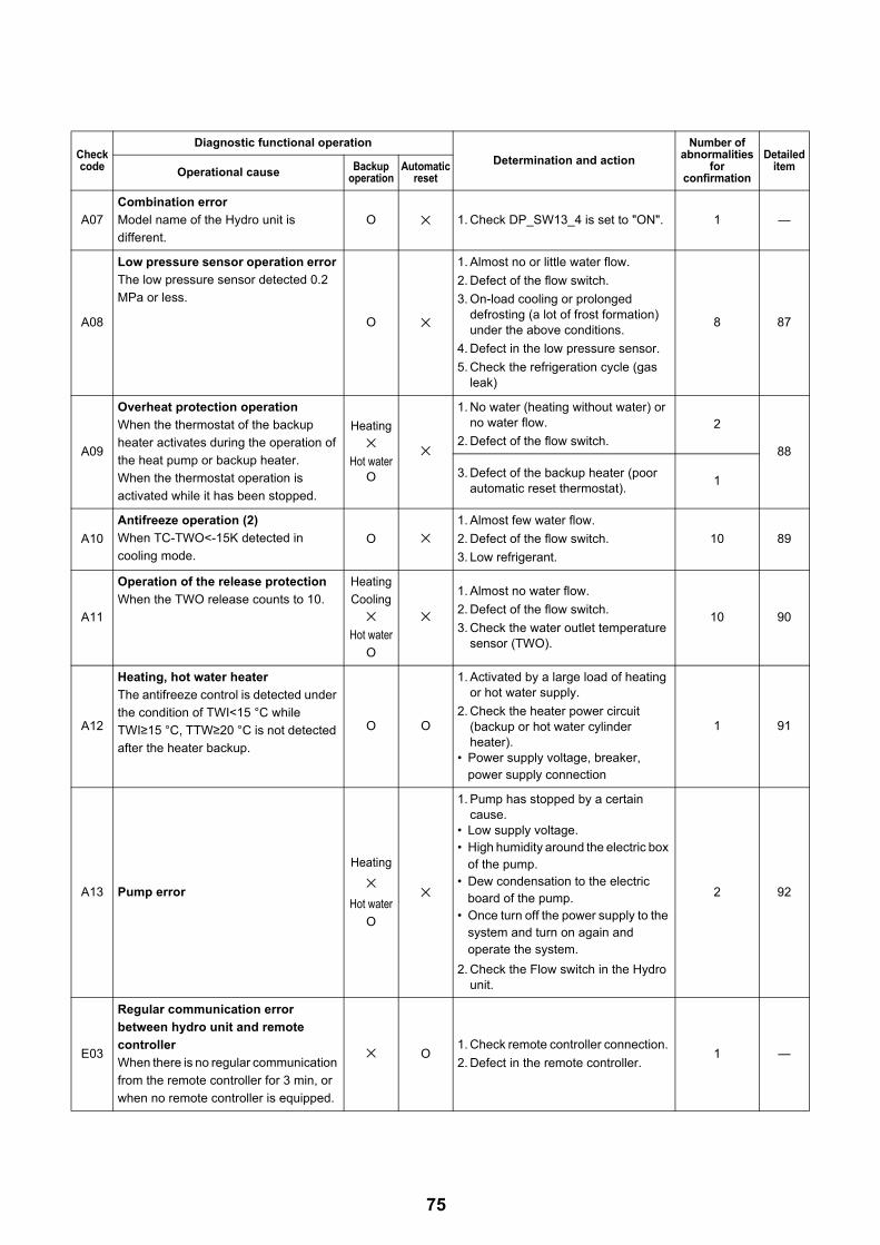
A07
Combination error
Model name of the Hydro unit is
different.
O × 1. Check DP_SW13_4 is set to "ON". 1 —
A08
Low pressure sensor operation error
The low pressure sensor detected 0.2
MPa or less.
O ×
1. Almost no or little water flow.
2. Defect of the flow switch.
3. On-load cooling or prolonged defrosting (a lot of frost formation) under the above conditions.
4. Defect in the low pressure sensor.
5. Check the refrigeration cycle (gas leak)
8 87
A09
Overheat protection operation
When the thermostat of the backup
heater activates during the operation of
the heat pump or backup heater.
When the thermostat operation is
activated while it has been stopped.
Heating
×Hot water
O
×
1. No water (heating without water) or no water flow.
2. Defect of the flow switch. 2
88
3. Defect of the backup heater (poor automatic reset thermostat).
1
A10
Antifreeze operation (2)
When TC-TWO<-15K detected in
cooling mode.O ×
1. Almost few water flow.
2. Defect of the flow switch.
3. Low refrigerant.
10 89
A11
Operation of the release protection
When the TWO release counts to 10.
Heating
Cooling
×Hot water
O
×1. Almost no water flow.
2. Defect of the flow switch.
3. Check the water outlet temperature sensor (TWO).
10 90
A12
Heating, hot water heater
The antifreeze control is detected under
the condition of TWI<15 °C while
TWI≥15 °C, TTW≥20 °C is not detected
after the heater backup.
O O
1. Activated by a large load of heating or hot water supply.
2. Check the heater power circuit (backup or hot water cylinder heater).
• Power supply voltage, breaker, power supply connection
1 91
A13 Pump error
Heating
×Hot water
O
×
1. Pump has stopped by a certain cause.
• Low supply voltage.• High humidity around the electric box
of the pump.• Dew condensation to the electric
board of the pump.• Once turn off the power supply to the
system and turn on again and operate the system.
2. Check the Flow switch in the Hydro unit.
2 92
E03
Regular communication error
between hydro unit and remote
controller
When there is no regular communication
from the remote controller for 3 min, or
when no remote controller is equipped.
× O1. Check remote controller connection.
2. Defect in the remote controller.1 —
Check code
Diagnostic functional operation
Determination and action
Number of abnormalities
for confirmation
Detailed itemOperational cause Backup
operationAutomatic
reset
75
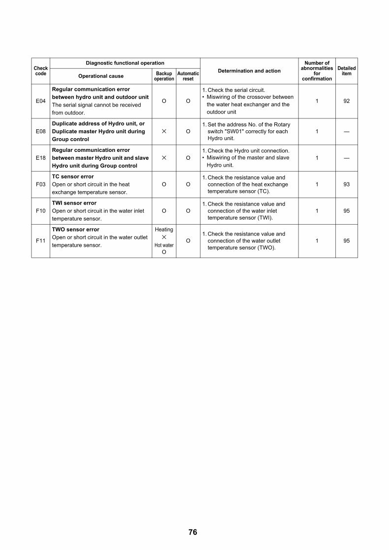
E04
Regular communication error
between hydro unit and outdoor unit
The serial signal cannot be received
from outdoor.
O O
1. Check the serial circuit. • Miswiring of the crossover between
the water heat exchanger and the outdoor unit
1 92
E08
Duplicate address of Hydro unit, or
Duplicate master Hydro unit during
Group control
× O1. Set the address No. of the Rotary
switch "SW01" correctly for each Hydro unit.
1 —
E18
Regular communication error
between master Hydro unit and slave
Hydro unit during Group control
× O1. Check the Hydro unit connection.• Miswiring of the master and slave
Hydro unit.1 —
F03
TC sensor error
Open or short circuit in the heat
exchange temperature sensor.
O O1. Check the resistance value and
connection of the heat exchange temperature sensor (TC).
1 93
F10
TWI sensor error
Open or short circuit in the water inlet
temperature sensor.
O O1. Check the resistance value and
connection of the water inlet temperature sensor (TWI).
1 95
F11
TWO sensor error
Open or short circuit in the water outlet
temperature sensor.
Heating
×Hot water
O
O1. Check the resistance value and
connection of the water outlet temperature sensor (TWO).
1 95
Check code
Diagnostic functional operation
Determination and action
Number of abnormalities
for confirmation
Detailed itemOperational cause Backup
operationAutomatic
reset
76

F14
TTW sensor error
Open or short circuit in the hot water
cylinder sensor.
Heating
×Hot water
O
O1. Check the resistance value and
connection of the hot water cylinder sensor (TTW).
1 96
F17
TFI sensor error
Open or short circuit in the floor
temperature sensor.
(Only when zone 2 is used)
Heating
×Hot water
O
O1. Check the resistance value and
connection of the floor-inlet temperature sensor (TFI).
1 96
F18
THO sensor error
Open or short circuit in the heater outlet
temperature sensor.
Heating
×Hot water
O
O1. Check the resistance value and
connection of the heater outlet temperature sensor (THO).
1 96
F19
Detection of THO disconnection error
When TWO–THO>15K is detected and
30 sec elapsed.
Heating
×Hot water
O
×1. Check for any disconnection of the
heater outlet temperature sensor (THO).
2. Defect of the flow switch.
1 97
F20
TFI sensor error
When TWO–TFI>40K is detected and
TFI<TWI–5K is detected 60 sec.
Heating
×Hot water
O
× 1. Check the connection of the floor-inlet temperature sensor (TFI).
1 98
F23
Low pressure sensor error
When PS<0.07 MPa is detected for 90
sec or more. (cooling, defrosting)
When PS<0.07 MPa is detected for 10
min or more. (hot water supply, heating)
O O
1. Check the connection (body or connection wiring) of the low pressure sensor.
2. Check the resistance value of the low pressure sensor.
3. Check the refrigeration cycle (gas leak)
1 99
F29
EEROM error
Inconsistency is detected once without
verify ACK after writing to EEPROM.
× × 1. Replace the water heat exchange control board.
1 99
F30Extended IC error
When the extended IC is abnormal. × × 1. Replace the water heat exchange
control board. 1 99
L02
Combination error
Model name of the outdoor unit is
different.
× × 1. Check the model name of the outdoor unit.
1 99
L07Communication error
Individual hydro units have a group line. × × 1. Replace the water heat exchange
control board. 1 99
L09
Communication error
The capability code for the hydro unit
has not been set.× ×
1. Check the setting of the FC01 capability specifications.
HWS-P805xx-E = 0012
HWS-P1105xx-E = 0015
1 100
L16
Setting error
When ZONE1 has not been set, while
ZONE2 has been set.
× × 1. Check the body DP-SW12_2,3. 1 100
P31
Slave Hydro unit error which occurs
when error occurs in master Hydro
unit × O
1. Check the remote controller connection.
2. Defect in the remote controller.
3. Set the address No. of the Rotary switch "SW01" correctly for each Hydro unit.
1 —
Check code
Diagnostic functional operation
Determination and action
Number of abnormalities
for confirmation
Detailed itemOperational cause Backup
operationAutomatic
reset
77

Defect mode detected by the outdoor unitO ... Possible× .... Not possible
Check code
Diagnostic functional operation
Determination and action
Number of abnormalities
for confirmation
Detailed itemOperational cause Backup
operationAutomatic
reset
F04
TD sensor error
Open or short circuit in the discharge
temperature sensor.
O ×1. Check the resistance value and
connection of the discharge sensor (TD).
494
110
F06
TE sensor error
Open or short circuit in the heat
exchange temperature sensor.
O ×1. Check the resistance value and
connection of the heat exchange temperature sensor (TE).
494
110
F07
TL sensor error
Open or short circuit in the heat
exchange temperature sensor.
O ×1. Check the resistance value and
connection of the heat exchange temperature sensor (TL).
494
110
F08
TO sensor error
Open or short circuit in the outdoor
temperature sensor.
O ×1. Check the resistance value and
connection of the outdoor temperature sensor (TO).
195
111
F12
TS sensor error
Open or short circuit in the suction
temperature sensor.
O ×1. Check the resistance value and
connection of the suction temperature sensor (TS).
4 111
F13
TH sensor error
Open or short circuit in the heat-sink
temperature sensor.
O ×1. Check the resistance value and
connection of the heat-sink temperature sensor (TH).
8 111
F15
TE, TS sensors error
TE, TS sensor connections are
opposite.O ×
1. Check for any wrong installation of the heat exchange temperature sensor (TE) and the suction temperature sensor (TS).
4 111
F24
PD sensor error
Open or short circuit in the high pressure
sensor.
O × 1. Check the value of PD sensor by the remote controller.
4 112
F31 EEPROM error O × 1 112
H01
Compressor breakdown
1 When the operation frequency lowers due to the current release 40 sec or later after the compressor activation and it stops by underrunning the minimum frequency.
2 When the operation frequency lowers due to the current limit control and it stops by underrunning the minimum frequency.
3 When an excess current is detected 0.8 sec or later after the compressor activation.
O ×
1. Check the power supply voltage (AC220-230 V±10%).
2. Over-loaded condition of the refrigeration cycle.
3. Check that the service valve is fully open.
8 101
H02
Compressor lock
1 When the input current is more than zero 20 sec or later after the compressor activation and the activation has not been completed.
O ×1. Defect of compressor (lock)
– Replace the compressor.
2. Defect of compressor wiring (open phase).
8 102
H03Defect in the current detection circuit
O × 1. Replace the outdoor inverter control board.
8 —
78

H04
Operation of case thermostat
When the case thermostat exceeds
125 °C.
O ×
1. Check the refrigeration cycle (gas leak).
2. Check the case thermostat and connector.
3. Check that the service valve is fully open.
4. Defect of the pulse motor valve.
5. Check for kinked piping.
10 102
L10Unset service PC board jumper
Jumpers J800-J803 have not been cut. O × 1. Cut J800-J803. 1 103
L15
Combination error
Model name of the Hydro unit is
different.
× ×1. Check the model name of the Hydro
unit.
2. Check DP_SW13_4 is set to "ON". 1 103
L29
The communication between the
outdoor PC board MUCs error
No communication signal between IPDU
and CDB.
O × 1. Replace the outdoor control board. 1 103
P03
The outlet temperature error
When the discharge temperature sensor
(TD) exceeds 111 °C. O ×
1. Check the refrigeration cycle (gas leak).
2. Defect of the pulse motor valve.
3. Check the resistance value of the discharge temperature sensor (TD).
4 103
P04 The high pressure switch error O × 10 104
P05
The power supply voltage error
When the power supply voltage is
extremely high or low.
O × 1. Check the power supply voltage. (AC220-230 V±10%).
8 105
P07
Overheating of heat-sink error
When the heat-sink exceeds 105 °C.
O ×
1. Check the thread fastening and heat-sink grease between the outdoor control board and the heat-sink.
2. Check the heat-sink fan duct.
3. Check the resistance value of the heat-sink temperature sensor (TH).
4 105
P15
Detection of gas leak
When the discharge temperature sensor
(TD) exceeds 106 °C for consecutive 10
min.
When the suction temperature sensor
(TS) exceeds 60 °C for cooling or 40 °C
for heating for 10 consecutive min.
When TG ≤ TC -10 K is detected and
TG ≤ TWI-15 K is detected 10min. (hot
water supply, heating)
When TG ≤ TE -12 K is detected for
10min. (cooling)
O ×
1. Check the refrigeration cycle (gas leak).
2. Check that the service valve is fully open.
3. Defect of the pulse motor valve.
4. Check for kinked piping.
5. Check the resistance value of the discharge temperature sensor (TD) and the suction temperature sensor (TS).
6. Check the PD sensor by remote controller.
8 106
P19
The 4-way valve inversion error
When the heat exchange temperature
sensor (TE) exceeds 30 °C or the
suction temperature sensor (TS)
exceeds 50 °C during the heat pump
operation.
O ×
1. Check the operation of the 4-way valve unit or the coil characteristics.
2. Defect of the pulse motor valve.
3. Check the resistance value of the heat exchange temperature sensor (TE) and the suction temperature sensor (TS).
4 107
Check code
Diagnostic functional operation
Determination and action
Number of abnormalities
for confirmation
Detailed itemOperational cause Backup
operationAutomatic
reset
79

P20
High pressure protection operation
When an abnormal stop occurs due to
the high pressure release control.
When the high pressure sensor (PD)
detects 4.05 MPa.
O ×
1. Check that the service valve is fully open.
2. Defect of the pulse motor valve.
3. Check the outdoor fan system (including clogging).
4. Over-filling of refrigerant.
5. Check the value of the high pressure sensor (PD).
6. The water piping is too short.Install a buffer tank, or set the setting temperature lower.
10 108
P22
Outdoor fan system error
When a DC fan rotor position detection
NG, element short circuit, loss of
synchronization, or abnormal motor
current occurs.
O ×
1. Check the lock status of the motor fan.
2. Check the connection of the fan motor cable connector.
3. Check the power supply voltage. (AC220~230 V±10%)
8 109
P26
Short circuit of the compressor driver
element error
When an abnormal short circuit of IGBT
is detected. O ×
1. P26 abnormality occurs when operating with the compressor wiring disconnected … Check the control board.
2. No abnormality occurs when operating with the compressor wiring disconnected … Compressor rare short.
8 109
P29
Compressor rotor position error
The rotor position in the compressor
cannot be detected.
O ×
1. Even if the connection lead wire of the compressor is disconnected, it stops due to an abnormality in the position detection … Replace the inverter control board.
2. Check the wire wound resistor of the compressor. Short circuit … Replace the compressor.
8 109
Check code
Diagnostic functional operation
Determination and action
Number of abnormalities
for confirmation
Detailed itemOperational cause Backup
operationAutomatic
reset
80

Defect mode detected by the remote controller
Check code
Diagnostic functional operation
Determination and actionOperational cause Status of air-
conditioning Condition
Not displaying at
all (cannot
operate by the remote controller)
No communication between hydro unit an remote controller• The remote controller wiring is not
connected correctly.• The hydro unit has not been turned
on.
Stop – Defect in the remote controller power supply
1. Check the remote controller wiring.
2. Check the remote controller.
3. Check the hydro unit power supply wiring.
4. Check the water heat exchange control board.
E01
No communication between hydro unit and remote controller• Disconnection of the crossover
between the remote controller and the base unit of the Hydro unit (detected on the remote controller side).
Stop(Automatic reset)
Displayed when the abnormality is detected.
Defect in the reception of the remote controller
1. Check the remote controller crossover.
2. Check the remote controller.
3. Check the hydro power supply wiring.
4. Check the water heat exchanger board.
E02
Defect in the signal transmission to the hydro unit. (Detected on the remote controller side)
Stop(Automatic reset)
Displayed when the abnormality is detected.
Defect in the transmission of the remote controller
1. Check the transmitter circuit inside the remote controller.
… Replace the remote controller.
E09
Several remote controller base units(Detected on the remote controller side)
Stop(The handset continues)
Displayed when the abnormality is detected.
1.2 Check several base units with the remote controller
… The base unit is only one, and others are handsets.
81

9-4. Diagnosis flow chart for each error code9-4-1. Hydro unit failure detection
[A01] Error Pump flow determination
Built-in circulationpump rotates
Replace TC sensor
Remove wasteDirt clogging inside water circuit
12 M or longer water pipe to a branch, or 5 or less branches
Fit buffer tank and the second pump
Attach or replace flow switch
Connect flow switch connector to board
No
No
(Identify causes, and resolve)
(strainer)
Excess air noise comes from inside
the pump
Flow switch is connected to board
Pump is connected to board
Flow switch is normal
Chattering noise comes from flow switch
Pump stops 2-3 minutes after its rotation
started
TC sensor characteristic is correct
Yes
Yes
[A01] occurs
Operation restarts
Water heat exchanger control board is defective, replace it
Performair vent
Flow shortage
No (No pump sound)
No
Connect pump connector to board
No
Replace flow switchNo
No
No
No
Yes
Flow switch is normal
Yes
Replace pumpYes
Yes
No
Yes
Yes
82

[A02] Error Temperature rise and error short circuit
• If Boiler setting is ON (DPSW13-2 is ON) and FC62 is “1”, the A02 error is not detected.
Replace TWI, TWO, and THO sensors
No
(TWI,TWO,THO ≥ 70 °C)
TWI, TWO, and THO sensor characteristics are
correct
Yes
NoWater outlet temperature is 70 °C
or higher
Yes
Correct water circuit (To prevent hot water of other circuits from entering)
YesHot water from boiler or other circuits does
not come in
No
Failure of backup heater (Too large heater input, thermostat short circuit)
Replace heater unit
YesBackup heater is energized
No(Measure heater current)
Start
Replace water heat exchange control board
Yes
Flow switch is normalNo
Replace flow switch
83

[A03] Error Temperature rise and error short circuit
Replace TTW sensorNo
(TTW ≥ 85 °C is detected)
TTW sensor characteristic is correct
Yes
NoHot water cylinder heater is energized
Yes
NoAt normal temperature, tank thermostat
is energized
Yes
Replace hot water cylinder thermostat
NoHot water cylinder thermostat operates
Yes
Operation temperature 82 °C
Start
Replace water heat exchange control board
Replace Mg-swNoMg-sw (RY05) for
heater operates
Yes
Operating noise at normal time
84
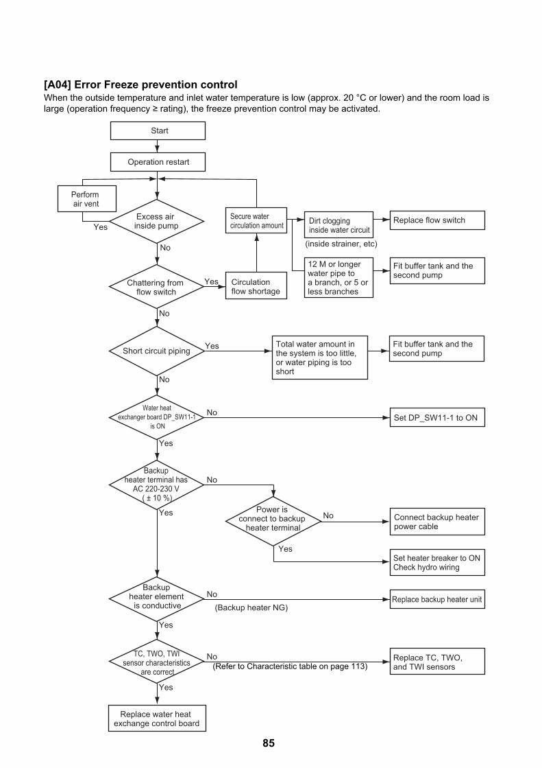
85
[A04] Error Freeze prevention controlWhen the outside temperature and inlet water temperature is low (approx. 20 °C or lower) and the room load is large (operation frequency ≥ rating), the freeze prevention control may be activated.
Excess air inside pump
Secure water circulation amount
Circulation flow shortage
Dirt clogging inside water circuit
12 M or longer water pipe to a branch, or 5 or less branches
Fit buffer tank and the second pump
Set DP_SW11-1 to ON
No
No
No
No (inside strainer, etc)
Chattering from flow switch
Water heat exchanger board DP_SW11-1
is ON
Power is connect to backup
heater terminal
Backup heater terminal has
AC 220-230 V ( ± 10 %)
Start
Operation restart
Replace water heat exchange control board
Perform air vent
Set heater breaker to ON Check hydro wiring
Replace flow switch
No
No
Yes
Yes
Yes
Yes
Replace backup heater unitNo(Backup heater NG)
(See Characteristic table on page 101)
Backup heater element
is conductive
Yes
Replace TC, TWO, and TWI sensors
NoTC, TWO, TWI sensor characteristics
are correct
Yes
Connect backup heater power cable
Yes
YesShort circuit pipingFit buffer tank and the second pump
Total water amount in the system is too little, or water piping is too short
(Refer to Characteristic table on page 113)

[A05] Error Piping freeze prevention control
Water heat exchange control board
DPSW11-1 is ON
Replace backup heater and safety valve
Set water heat board DPSW11-1 to ON
No
(Backup heater NG)
Backup heater terminal has 220-230 V (± 10 %)
Power is connect to built-in heater terminal
Yes
Yes
Restart
TWI 4, TWO 4, or THO 4 is detected
Circulation pump keeps being energized or 3 minutes
passed after the start
No
No
Place power cable for backup heater
Set breaker for backup heater to ON, or Check hydro electronic wiring
No
Backup heater element is conductive
Yes
Replace TWI, TWO, and THO sensors
NoTWI, TWO, THO sensor characteristics
are correct
Yes
Yes
Replace water heat exchange control board
(Refer to Characteristic table on page 113)
86

[A08] Error Low pressure sensor lowering operation failure (Cooling / Defrosting operation)
Replace flow switch
Remove waste
Flow switch is normal
Secure water circulation amount
Circulation flow shortage
Waste stuck inside water circuit
12 M or longer water pipe to a branch, or 5 or less branches
Remove sufficiently excess air
Place buffer tank and the second pump
No
Excess air noise comes from
inside pump
Chattering noise comes from
flow switch
Start
No
No
Yes
Raise set temperatureYes
(Cooling overload operation)
Continued operation at low outside
temperature and at 15 °C or lower set temperature
No
Defrost outdoor unit where frost remains
YesDefrosting takes 15 mins or longer
(Frost remains)
No
Replace low pressure sensorNoLow pressure sensor is normal
Yes
Yes
Yes
Replace water heat exchange control board
87

[A09] Error Overheat prevention thermostat failure (Hot water supply / Heating operation)
Put water into water circuit (Recommended: 1 - 2 Bar)
Replace heater unit exchanger air vent valve
Replace flow switch
No
No
Water cycle contains water
Yes
Flow switch is normal
Yes
NoAt normal temperature, overheat preventive thermostat
is normal
Yes
Start
Replace water heat exchange control board or overheat preventive thermostat failure
*Replace water heat exchange control board or overheat preventive thermostat failure: After the control board is replaced, if the same operation repeats, the overheat preventive thermostat is determined as defective (does not operate at 75 °C).
88

[A10] Error Freeze prevention control (2) (Cooling only)
No
Note: Determined at TWO-TWI temperature during operation at a pressure of Ps
No
Yes
Yes
Sufficient refrigerant
Operating with no load on water
circuit?
Replace flow switch
Remove waste
Flow switch is normal
Secure water circulation amount
Circulation flow shortage
Replace control board.
Waste stuck inside water circuit
12 M or longer water pipe to a branch, or 5 or less branches
Remove sufficiently excess air
Place buffer tank and the second pump
Recharge refrigerant
Raise the set water temperature.Add fan coils.
No
Excess air noise comes from
inside pump
Chattering noise comes from
flow switch
Start
No
No
Yes
Yes
Yes
89

[A11] Error Release protection operation
Replace flow switch
Remove waste
Flow switch is normal
Secure water circulation amount
Circulation flow shortage
Waste stuck inside water circuit
12 M or longer water pipe to a branch, or 5 or less branches
Remove sufficiently excess air
Place buffer tank and the second pump
No
Excess air noise comes from
inside pump
Chattering noise comes from
flow switch
Start
No
No
Yes
Attach TWI sensorNoTWI sensor is attached to pipe
Yes
Replace TWI or TWO sensorNoTWI and TWO sensor characteristics
are normal
Yes
Yes
Yes
Replace water heat exchange control board
90

[A12] Error Heating or Hot water supply heater failure
Water heat exchanger board DPSW11-1,2
is ON
Replace booster heater unit and safety valve
Set water heat board DPSW11-1,2 to ON
A12 abnormality detection
No
(Backup heater NG)
Backup heater or hot water cylinder terminal
has 220-230 V ± 10 %AC220-230 V±10 %=(single phase type).
AC380-400 V±10 %=(3 phase type).
Power is connect to backup heater or hot water
cylinder terminal
Yes
Yes
Restart
Operation starts under 10 ≤ TWI 20 °C
Heater backup operation Heating: Booster heater Hot water supply: Hot water cylinder heater
After 1 hour since heater operation started, neither TWI ≥ 15 °C nor TTW ≥ 20 °C is met
Freeze prevention control is detected once
No
No
Place electric wire for backup heater Place electric wire for hot water cylinder
Set breaker for backupheater to ONSet breaker for hot water cylinder to ONor check hydro wiring
No
Backup heater element is conductive
Yes
Replace hot water cylinder heater
No
(Hot water cylinder heater NG)
Hot water cylinder heater element
is conductive
Yes
Replace TWI or TTW sensor
NoTWI, TTW sensor characteristics are
normal
Yes
Yes
(Refer to hot water cylinder guide)
Replace water heat exchange control board
(Refer to Characteristic table on page 113)
91

[A13] Pump error
Input appropriate voltage
Yes
Yes
Start
No
No
Reject the factor
Replace pump
Input voltage is appropriate
The water pump is locking by some factor
92

[E04] Error
[F03] Error TC sensor failure
Outdoor unit operates
Yes
Check water heat exchanger control board
If defective, replace itCheck outdoor control board
If defective, replace it
NoYes
Hydro unit Internal wiring and
connecting wire (1, 2, 3) are correct
Correct wiring and connecting wire
No
Yes
CN04 connector and terminal block (1, 2, 3) wiring
are normalCorrect connector and terminal block wiring
No
Yes
When power is on again, D502 (Amber LED)
blinks
Check water heat exchanger board If defective, replace it
No
Yes
Correct TC sensor connection
Replace TC sensor
No
No
TC sensor connector (CN203) is
connected
Yes
TC sensor resistance characteristic
is normal
Yes
Start
Replace water heat exchange control board
93

[F04] Error TD sensor failure
[F06] Error TE sensor failure
[F07] Error TL sensor failure
Correct TD sensor connection
Replace TD sensor
No
No
TD sensor connector (CN603) is
connected
Yes
TD sensor resistance characteristic
is normal
Yes
Start
Replace water heat exchange control board
(Refer to Characteristic table on page 113)
Correct TE sensor connection
Replace TE sensor
No
No
TE sensor connector (CN601) is
connected
Yes
TE sensor resistance characteristic
is normal
Yes
Start
Replace water heat exchange control board
(Refer to Characteristic table on page 113)
Correct TL sensor connection
Replace TL sensor
No
No
TL sensor connector (CN604) is
connected
Yes
TL sensor resistance characteristic
is normal
Yes
Start
Replace water heat exchange control board
(Refer to Characteristic table on page 113)
94

[F08] Error TO sensor failure
[F10] Error TWI sensor failure
[F11] Error TWO sensor failure
Correct TO sensor connection
Replace TO sensor
No
No
TO sensor connector (CN602) is
connected
Yes
TO sensor resistance characteristic
is normal
Yes
Start
Replace water heat exchange control board
(Refer to Characteristic table on page 113)
Correct TWI sensor connection
Replace TWI sensor
No
No
TWI sensor connector (CN205) is
connected
Yes
TWI sensor characteristic is normal
Yes
Start
Replace water heat exchange control board
(Refer to Characteristic table on page 113)
Correct TWO sensor connection
Replace TWO sensor
No
No
TWO sensor connector (CN205) is
connected
Yes
TWO sensor characteristic is normal
Yes
Start
Replace water heat exchange control board
(Refer to Characteristic table on page 113)
95
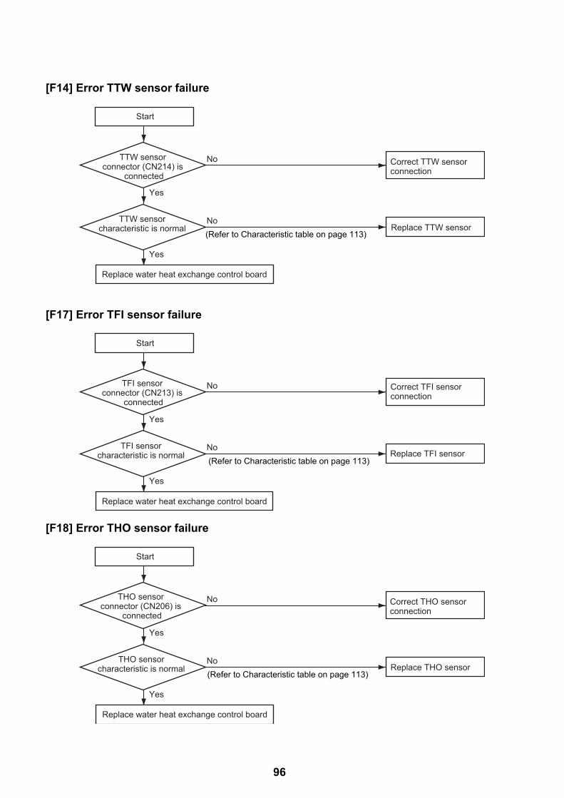
[F14] Error TTW sensor failure
[F17] Error TFI sensor failure
[F18] Error THO sensor failure
Correct TTW sensor connection
Replace TTW sensor
No
No
TTW sensor connector (CN214) is
connected
Yes
TTW sensor characteristic is normal
Yes
Start
Replace water heat exchange control board
(Refer to Characteristic table on page 113)
Correct TFI sensor connection
Replace TFI sensor
No
No
TFI sensor connector (CN213) is
connected
Yes
TFI sensor characteristic is normal
Yes
Start
Replace water heat exchange control board
(Refer to Characteristic table on page 113)
Correct THO sensor connection
Replace THO sensor
No
No
THO sensor connector (CN206) is
connected
Yes
THO sensor characteristic is normal
Yes
Start
Replace water heat exchange control board
(Refer to Characteristic table on page 113)
96

[F19] Error THO sensor detach failure
Attach THO sensor to pipe
Replace THO sensor
No
No
THO sensor is attached to pipe
Yes
THO sensor characteristic is normal
Yes
Replace TWO sensorNoTWO sensor
characteristic is normal
Yes
Start
Replace water heat exchange control board
(Refer to Characteristic table on page 113)
(Refer to Characteristic table on page 113)
97
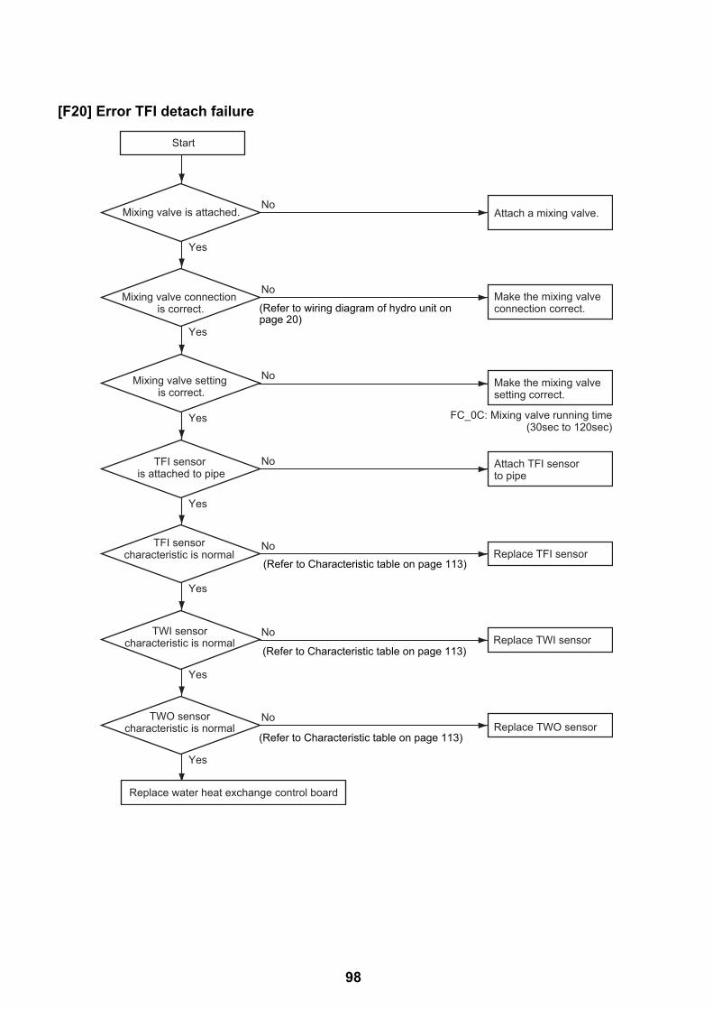
[F20] Error TFI detach failure
Attach TFI sensor to pipe
Replace TFI sensor
No
No
TFI sensor is attached to pipe
Yes
TFI sensor characteristic is normal
Yes
Replace TWI sensorNoTWI sensor
characteristic is normal
Yes
Attach a mixing valve.
Make the mixing valve connection correct.
Make the mixing valve setting correct.
No
No
Mixing valve is attached.
Yes
Mixing valve connection is correct.
Yes
No
FC_0C: Mixing valve running time(30sec to 120sec)
Mixing valve setting is correct.
Yes
Replace TWO sensorNoTWO sensor
characteristic is normal
Yes
Start
Replace water heat exchange control board
(Refer to Characteristic table on page 113)
(Refer to Characteristic table on page 113)
(Refer to Characteristic table on page 113)
(Refer to wiring diagram of hydro unit on page 20)
98

[F23] Error Low pressure sensor detach failure
[F29] Error EEPROM failure
A failure is detected in the IC10 non-volatile memory on the water heat exchanger board during a hot water supply unit operation. Replace the service board.
* If the unit does not have EEPROM inserted when the power is turned on, or if EEPROM data read or write is unavailable, automatic address mode repeats. In this case, the intensive control unit displays [97 Abnormal].
[F30] Error Enhanced IC failure
Enhanced IC on water heat exchanger control board is abnormal.Replace the water heat exchanger control board to a service board.
[L02] Combination Error
The model name of the outdoor unit is not HWS-P805HR-E or HWS-P1105HR-E.Replace the outdoor unit with the proper model.
[L07] Error
At the time of power on, detecting the above failure automatically activates the automatic address setting mode.(Check code is not output)Note that if the above failure is detected in the automatic address setting mode, a check code may be output.
Attach low pressure sensor
Replace low pressure sensor
Yes
No
Low pressure sensor is detached (CN207, 212)
No
When operation is stopped, low pressure sensor
is normal *1
Yes
Start
*1 How to determine: When operation is stopped
Replace water heat exchange control board
(Power on) Handy remote controller displays "Setting"
"Setting" disappears
Reboot (reset)
(Repeat)
(Approx. 3 mins) (Approx. 1 mins)
99
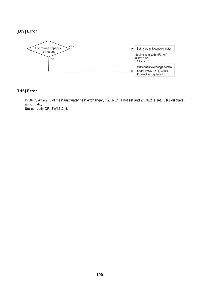
[L09] Error
[L16] Error
In DP_SW12-2, 3 of main unit water heat exchanger, if ZONE1 is not set and ZONE2 is set, [L16] displays abnormality.Set correctly DP_SW12-2, 3.
No
Set hydro unit capacity data
Setting item code (FC_01)8 kW = 1211 kW = 15
Water heat exchange control board (MCC-1511) Check If defective, replace it
YesHydro unit capacity is not set
100

9-4-2. Outdoor unit failure detection
Diagnosis procedure for each check code• One check code may indicate multiple symptoms. In such a case, see the LED indication on the outdoor board
to narrow down the check details.• The handy remote controller displays a check code only when the same failure repeatedly occurs while the LED
on the outdoor board indicates an error even if it occurs only once. This may cause indication inconsistency between the remote controller and LED.
Outdoor board LED indication method
Dip switch setting• Setting 1 only of SW803 to ON indicates the latest failure.
Because the error log is recorded, you can see the detail even after the power is once turned off. (Not including outside air temperature sensor (TO) failure)
• After check work is done or when outside air temperature sensor (TO) failure is detected, set all the SW803 switches to OFF.(An abnormality now is indicated.)
Indication switching• One or more LEDs of D800 through D804 lit yellow indicates
that a failure occurred. <Indication 1>• With the status above, pressing the SW800 button for one
second causes the yellow LED to blink. <Indication 2>• Pressing again SW800 for one second or longer returns to
<Indication 1>.• The combination of <Indication 1> and <Indication 2> can
determine what kind of abnormality.
Check code Outdoor LED indication
Check and Action procedure (No specific description indicates outdoor unit parts.)
[H01] <Indication 1> <Indication 2> [Compressor fails]
1ON
23
4
<Latest abnormality>SW803 1 only is ON
1ON
23
4
<Abnormality now>SW803 All OFF (Initial status)
D800 (yellow)D801 (yellow)D802 (yellow)D803 (yellow)D804 (yellow)D805 (green)
Off Light Blink
(Normal) (Abnormality occurs)(Press SW800)
(Example of outlet temperature sensor failure)
<Indication 1> <Indication 2>
Improve power line
Check outdoor control board If defective, replace it
No
Yes
Abnormally over loaded
PC boardP805HR-E, P1105HR-E (MCC-1571)
Deal with or remove causesYes
No
Wiring connection is normal. Compressor lead (Board side, compressor side reactor lead, power lead)
Check and correct wiring connection
No
Yes
Power voltage is normal. AC220-230 V±10 %
101

[H02] <Indication 1> <Indication 2> [Compressor lock]
[H04] <Indication 1> <Indication 2> [Case thermostat operation]
Check code Outdoor LED indication
Check and Action procedure (No specific description indicates outdoor unit parts.)
Improve power line
Check outdoor board If defective, replace it
No
Yes
Compressor is normal.
Lock compressor and replace it.
No
Yes
Refrigerant stays inside. No
Yes
TE, TS sensor pulse motor valve check If defective, replace
Pulse motor valve operates normally.
No
Yes
Wiring connection is normal. Compressor lead (board side, compressor side) reactor, power lead
Check and correct wiring connection
No
Yes
Power voltage is normal. AC220-230 V±10 %
PC boardP805HR-E, P1105HR-E (MCC-1571)
CN609 connector and case thermostat is normal.
Correct connector Replace case thermostat
Check for piping collapse and break. If defective, repair or replace it.
No
Yes
If case thermostat is short circuited, cooling and heating can operate.
Check outdoor board If defective, replace it
No
Yes
No gas leakage. Enough Refrigerant.
Correct defective portion Re-charge refrigerant
No
Yes
Service valve is fully opened. Open fully service valveNo
Yes
Pulse motor valve is normal. Correct defective portion Replace defective parts
No
Yes
PC boardP805HR-E, P1105HR-E (MCC-1571)
102

[L10] <Indication 1> <Indication 2> [Model not set] Only when service board is used
[L15] <Indication 1> <Indication 2> [Combination failure between the hydro unit]
[L29] * Any of the following abnormality may occur.Seeing the LED on the outdoor board can determine which abnormality occurs.
Communication failure between MCUs, Heat sink temperature sensor (TH) failure, EEPROM failure, Model not specified, Heat sink overheat failure, gas leakage detection, 4-way valve invert failure
<Indication 1> <Indication 2> [Communication failure between MCUs]
[P03] <Indication 1> <Indication 2> [Abnormal outlet temperature]
Check code Outdoor LED indication
Check and Action procedure (No specific description indicates outdoor unit parts.)
Cut jumper line by following the instruction comes with the service board package
Replace the hydro unit with the proper model
Check outdoor control boardIf defective, replace it
PC boardP805HR-E,P1105HR-E(MCC-1571)
No gas leakage. Appropriate refrigerant amount.
Correct defective portion Re-charge refrigerant
Check outdoor control board If defective, replace it
No
Yes
Pulse motor valve is normal. Correct defective portion Replace defective parts
No
Yes
Abnormally over loaded Deal with or remove causes
Yes
No
CN603 connector is normal.TD sensor resistance is normal
Correct connector Replace sensor
No
YesPC boardP805HR-E,P1105HR-E(MCC-1571)
103

[P04] * Any of the following abnormality may occur.Seeing the LED on the outside board can determine which abnormality occurs.
1.High pressure sensor activated.2.Power source failure (Vdc)3.Hi pressure protection operation4.Case thermostat operation
<Display 1> <Display 2> [High pressure SW system error]Power supply error (Vdc), High pressure protective operation, Case thermostat operation.
Check code Outdoor LED indication
Check and Action procedure (No specific description indicates outdoor unit parts.)
Connection of connectors,Fan IPDU, Fan motor, Wiring.
Is circuit wiring normal?
Is there no fan breakageor coming-off?
Is service valve fully opened?
Does cooling outdoor fannormally operate?
B Cooling operation.
B Cooling operation C Heating operation
Doesn’t high pressure switchoperate?
Are parts ofhigh pressure switch normal?
Reset the power supply andthen do a test run according
to the season.
Is there any elementwhich blocks heat exchanger
of the outdoor unit? Clogging of heat exchanger Short circuit
Parts checkDefective → Replace
Elimination ofblocking element
Check Comp. IPDU PC boardDefective → Replace
Wiring check,Correct.
Open service valve fully
←←
.
Repair defective position.
Overcharge of refrigerant /Clogging / Pipe breakage /
Abnormal overload
YES
YES YES
YES YES
YES
NO
NO NO
NO
NO
NO
YES
NO
1.2.
Are characteristicsof TC and TCJ sensor
resistance value normal?
Are connections ofconnectors,capacitorsand fan motor normal?
Heating operation
Does the heating outdoor fannormally operate?
Clogging by refrigerantovercharge / Pipe breakage /
Abnormal overload
C
Is there any element whichblocks hydro heat exchanger?
Filter clogging Clogging of heat exchanger Shor3.
2.1.
t circuit
Elimination ofblocking element
Repairdefective position.
ReplaceTC or TCJ sensor.
Check hydro PC boardDefective Replace
YES YES
YES
NO NO
YES
NO
NO
→
104

[P05] <Indication 1> <Indication 2> [Power source failure (voltage defective, open phase)]
[P07] <Indication 1> <Indication 2> [Heat sink overheat failure]
Check code Outdoor LED indication
Check and Action procedure (No specific description indicates outdoor unit parts.)
Check outdoor control board If defective, replace it
Check electric workYes
No
Power voltage abnormal drops or rise (AC220-230 V±10 %: single phase)
PC boardP805HR-E,P1105HR-E(MCC-1571)
Check outdoor control board If defective, replace it
Yes
Yes
No
The screws are loose in motor drive element,
Q200/300/400, of outdoorcontrol board and rectifier,DB01/02/03. (MCC-1571)Radiation grease was not
applied to backside ofQ200, DB01, DB02,
or DB03.
No
Is not the ventilation flueof the heat sink blocked?Is not the fan blocked?
(Short-circuit, etc.)
HWS-P805HR-E, P1105HR-E
Remove obstacles, Deal with short circuit
Apply radiation grease as needed Tighten screws(Be sure to place back the insulation sheet between Q300/400 and the heat sink.)
105

[P15] <Indication 1> <Indication 2> [Gas leakage detection]
Check code Outdoor LED indication
Check and Action procedure (No specific description indicates outdoor unit parts.)
Check outdoor control board If defective, replace it
No gas leakage. Appropriate refrigerant amount.
Correct defective portion Re-charge refrigerant
No
Yes
Pulse motor valve is normal. Correct defective portion Replace defective parts
No
Yes
Service valve is fully opened. Open fully service valveNo
Yes
Piping collapse Repair or replace pipe Yes
No
Temperature sensor check Discharge sensor CN603 Suction sensor CN600
Correct connector Replace sensor
NG
OK
PC boardP805HR-E, P1105HR-E (MCC-1571)
106

[P19] <Indication 1> <Indication 2> [4-way valve invert failure]
Outdoor control board operation check direction (Self-hold valve) = P805HR-E, P1105HR-E
1)With the dip switch SW804 set as in the table below, pressing SW801 for approx. 1 second can check the operation of switching to cooling cycle or to heating cycle.• The board are energized for 10 seconds.• Take more than a minute for the next check because the parts (coil, resistance R700)
generate large heat. (This does not apply when no coil is connected.)
2)After the check, set all the SW804 dip switches to OFF.
Note: Check with a testerWith an analog tester: If a tester shows 180DCV or higher, the board is good. With digital tester: Although values shown has some range, if its maximum value is
180DCV or higher, the board is good.
Check code Outdoor LED indication
Check and Action procedure (No specific description indicates outdoor unit parts.)
Temperature sensor check TE sensor CN601 TS sensor CN600 Hydro TWO sensor If defective, repair or replace it
4-way valve check If defective, replace it
4-way valve operates normally. (Check piping temperature at the time of cooling/heating operation)
No
Yes
Replace 4-way coil4-way valve coil resistance is 1.3 to 1.6 k .
No
Yes
Outdoor control board operation check (See below)
NG
OK
Check outdoor board If defective, replace it
Switching to cooling cycle Switching to heating cycle
CN701SW804 SW801
180DCV or higher
Press1ON
23
4
CN701SW804 SW801
180DCV or higher
Press1ON
23
4
107

[P20] <Indication 1> <Indication 2> [Hi pressure protection operation]
Check code Outdoor LED indication
Check and Action procedure (No specific description indicates outdoor unit parts.)
No
Yes
Service valve is fully opened. No Open fully service valve
Yes
Outdoor PD sensor is normal.(confirmation by remote controller)
Cooling season Cooling operation
Heating season Heating operation
No Replace sensor
Yes Remove the disturbing element
Yes
Outdoor fan is free from crack or looseness.
No Check outdoor fan If defective, replace or tighten it
Yes
Outdoor fan operates normally. No Check the same item as those for [P22] abnormality
Reset the power source and perform a trail operation according to the season.
Something prevents outdoor unit heat exchange - Clogged heat exchanger - short circuit
No
Yes
Check for refrigerant overcharged, clogged cycle, pipe break, abnormal overload, etc. If defective, repair defective portion
Check for refrigerant overcharged, clogged cycle, pipe break, abnormal overload, etc. If defective, repair defective portion
Remove the disturbing element
Something prevents heat exchange of hydro unit. - Clogged filter - Clogged heat exchanger - Short circuit
108
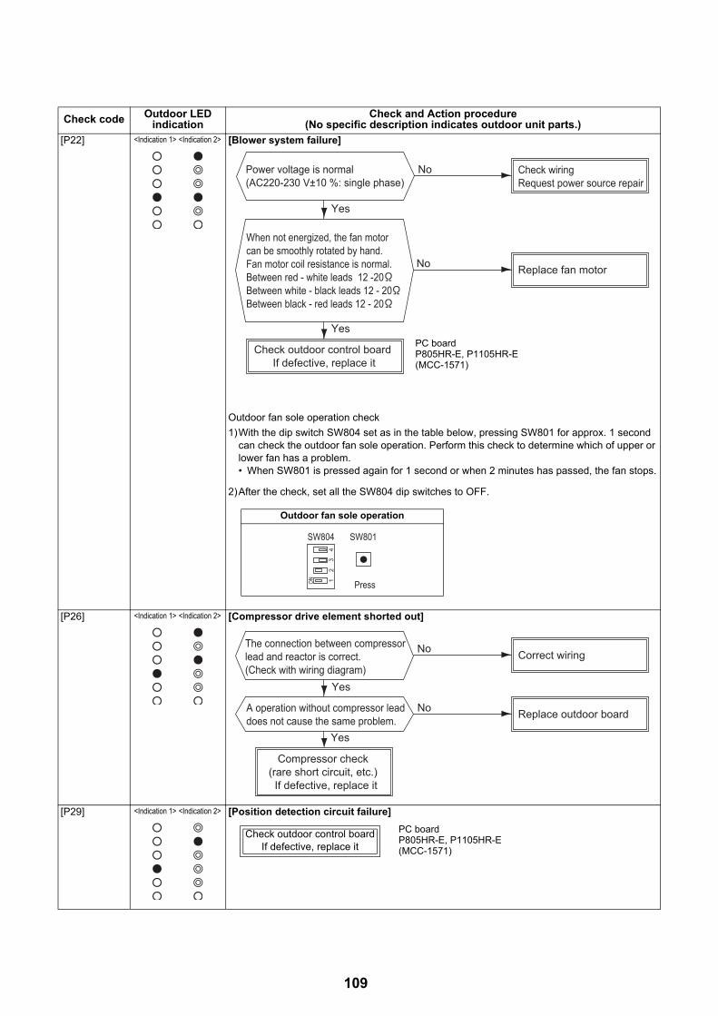
[P22] <Indication 1> <Indication 2> [Blower system failure]
Outdoor fan sole operation check
1)With the dip switch SW804 set as in the table below, pressing SW801 for approx. 1 second can check the outdoor fan sole operation. Perform this check to determine which of upper or lower fan has a problem.• When SW801 is pressed again for 1 second or when 2 minutes has passed, the fan stops.
2)After the check, set all the SW804 dip switches to OFF.
[P26] <Indication 1> <Indication 2> [Compressor drive element shorted out]
[P29] <Indication 1> <Indication 2> [Position detection circuit failure]
Check code Outdoor LED indication
Check and Action procedure (No specific description indicates outdoor unit parts.)
Check outdoor control board If defective, replace it
No
Yes
Yes
Check wiring Request power source repair
When not energized, the fan motor can be smoothly rotated by hand. Fan motor coil resistance is normal. Between red - white leads 12 -20Between white - black leads 12 - 20Between black - red leads 12 - 20
No Replace fan motor
Power voltage is normal(AC220-230 V±10 %: single phase)
PC boardP805HR-E, P1105HR-E(MCC-1571)
Outdoor fan sole operation
SW804 SW801
Press1ON
23
4
Compressor check (rare short circuit, etc.) If defective, replace it
The connection between compressor lead and reactor is correct. (Check with wiring diagram)
No
Yes
Yes
Correct wiring
No Replace outdoor boardA operation without compressor lead does not cause the same problem.
Check outdoor control boardIf defective, replace it
PC boardP805HR-E, P1105HR-E(MCC-1571)
109

No code <Indication 1> <Indication 2> [Discharge abnormality] Compressor's loss of synchronism due to rapid load change, etc.* Although the outdoor LED indicates abnormality, the compressor restarts and no abnormality
is confirmed.* This may occur due to the open phase of the compressor or wiring detach.
[F04] <Indication 1> <Indication 2> [Discharge temperature sensor (TD) failure]
[F06] <Indication 1> <Indication 2> [Heat exchanger temperature sensor (TE) failure]
[F07] <Indication 1> <Indication 2> [Heat exchanger temperature sensor (TL) failure]
Check code Outdoor LED indication
Check and Action procedure (No specific description indicates outdoor unit parts.)
TD sensor connector (CN603) is connected
Correct TD sensor connection
Replace outdoor control board
No
TD sensor resistance characteristic is normal Replace TD sensor
No
Yes
Yes
PC boardP805HR-E, P1105HR-E (MCC-1571)
See the characteristic table on page 92
TE sensor connector (CN601) is connected
Correct TE sensor connection
Replace outdoor control board
No
Yes
TE sensor resistance characteristic is normal Replace TE sensor
No
Yes
PC boardP805HR-E, P1105HR-E (MCC-1571)
See the characteristic table on page 92
TL sensor connector (CN604) is connected
Correct TL sensor connection
Replace outdoor control board
No
YES
TL sensor resistance characteristic is normal Replace TL sensor
No
YES
PC boardP805HR-E, P1105HR-E (MCC-1571)
See the characteristic table on page 92
110

[F08] <Indication 1> <Indication 2> [Outside air temperature sensor (TO) failure]
[F12] <Indication 1> <Indication 2> [Suction temperature sensor (TS) failure]
[F13] <Indication 1> <Indication 2> [Heat sink temperature sensor (TH) failure]
[F15] <Indication 1> <Indication 2> [Heat exchanger sensor (TE, TS) wrong wiring]
Check code Outdoor LED indication
Check and Action procedure (No specific description indicates outdoor unit parts.)
TO sensor connector (CN602) is connected
Correct TO sensor connection
Replace outdoor control board
No
Yes
TO sensor resistance characteristic is normal Replace TO sensor
No
Yes
PC boardP805HR-E, P1105HR-E (MCC-1571)
See the characteristic table on page 92
TS sensor connector (CN600) is connected
Correct TS sensor connection
Replace outdoor control board
No
Yes
TS sensor resistance characteristic is normal
Replace TS sensorNo
Yes
PC boardP805HR-E, P1105HR-E (MCC-1571)
Replace outdoor control board PC boardP805HR-E, P1105HR-E (MCC-1571)
TE and TS sensor is attached to the correct position.
Correct sensor attaching position
Replace outdoor control board
No
Yes
TE sensor resistance characteristic is normal Replace TE sensor
No
Yes
TS sensor resistance characteristic is normal Replace TS sensor
No
Yes
PC boardP805HR-E, P1105HR-E (MCC-1571)
See the characteristic table on page 92
See the characteristic table on page 92
111

[F24] <Indication 1> <Indication 2> [High pressure sensor (PD) failure]
[F31] <Indication 1> <Indication 2> [EEPROM failure]
Check code Outdoor LED indication
Check and Action procedure (No specific description indicates outdoor unit parts.)
PD sensor connector (CN606) is connected
Correct PD sensor connection
Replace outdoor control board
No
Yes
PD sensor is normal Replace PD sensorNo
Yes
Check outdoor control boardIf defective, replace it
PC boardP805HR-E, P1105HR-E (MCC-1571)
112

9-4-3. Temperature sensor, temperature-resistance characteristic table
TC, TWI, TWO, TFI, TTW, TE, TS, TO sensors TD, TL sensors
Typical value Typical value
Temperature (°C)
Resistance value (kΩ) Temperature (°C)
Resistance value (kΩ)
(Minimum) (Standard) (Maximum) (Minimum) (Standard) (Maximum)
-10 55.42 55.73 60.04 0 150.5 161.3 172.7
0 32.33 33.80 35.30 10 92.76 99.05 105.6
10 19.63 20.35 21.09 20 58.61 62.36 66.26
20 12.23 12.59 12.95 25 47.01 49.93 52.97
25 9.75 10.00 10.25 30 37.93 40.22 42.59
30 7.764 7.990 8.218 40 25.12 26.55 28.03
40 5.013 5.192 5.375 50 17.00 17.92 18.86
50 3.312 3.451 3.594 60 11.74 12.34 12.95
60 2.236 2.343 2.454 70 8.269 8.668 9.074
70 1.540 1.623 1.709 80 5.925 6.195 6.470
80 1.082 1.146 1.213 90 4.321 4.507 4.696
90 0.7740 0.8237 0.8761 100 3.205 3.336 3.468
100 0.5634 0.6023 0.6434
0-100
10
20
30
40
50
60
10 20 30 40 50 60 70 80 90 100
00 0
5
10
15
20
50
100
150
200
10 20 30 40 50 60 70 80 90 100
Res
ista
nce
(k
Temperature (°C)
TC, TWI, TWO, TFI, TTW, TE, TS, TO sensors
Res
ista
nce
(k
) (50
°C o
r low
er)
Res
ista
nce
(k
) (50
°C o
r hig
her)
Temperature (°C)
TD, TL sensors
* Since the TH sensor (outdoor unit heat-sink temperature sensor) is built in the outdoor control board, the resistance value cannot be measured.
113

9-5. Operation check by PC board switch9-5-1. Operation check modeThis mode allows to check the operations of the water 2-way valve, water 3-way valve, mixing valve, and circulation pump. This operation is valid when the hydro unit and the outdoor unit are turned on the power.
Operation check mode(1) Preparation
1) Turn all of the remote controllers "OFF" for the hot water supply and heating.
2) Turn off the hydro unit and the outdoor unit.
3) Remove the front panel of the hydro unit.
4) Set SW06_2 "ON".
(2) Operation check
1) Turn on the hydro unit and the outdoor unit.
2) Rotate switch DIP SW01 to position "1" and press tactile switch SW07 for 5 sec. or longer.
3) Rotating the rotary SW01 allows to check each operation.
4) Set the DIP SW06_2 "OFF" to finish.
Rotary switch Check contents Remark
1 None
22WV_W Alive for approx. 2 sec, not alive for 3
sec
3 3WV_W
4Mixing valve Alive for 30 sec in the forward direction
Alive for 30 sec in the reverse direction
5 Built-in circulation pump Alive / not alive for 20 sec
6 External circulation pump 1 Alive / not alive for 20 sec
7 (External circulation pump 2) Alive / not alive for 20 sec Reserved
8Water heat exchange backup
heater
Repeat heater 1, heater 2, and OFF
every 20 sec
The built-in circulation pump operates.
9 Hot water cylinder heater Alive / not alive for 10 sec
10Backup heater Alive / not alive for 10 sec The built-in circulation pump and external
circulation pump operate.
11 Check the alarm output. Output for 10 sec / no output for 10 sec
12 Check the boiler output. Output for 10 sec / no output for 10 sec
13 Check the defrost output. Output for 10 sec / no output for 10 sec
14 Check the operation output. Output for 10 sec / no output for 10 sec
15 None
16Built-in circulation pump
continuous operation
Continuously alive Do not operate the circulation pump alive
continuously without any water in hydro unit.
114

9-6. Brief method for checking the key components9-6-1. Hydro unit
No. Component name Check procedure
1
Water heat exchange
temperature
(TC) sensor
Water inlet temperature
(TWI) sensor
Water outlet temperature
(TWO) sensor
Hot water cylinder temperature
(TTW) sensor
Floor inlet temperature
(TFI) sensor
Remove the connector and measure the resistance value with a tester. (Normal temperature)
Temperature0 °C 10 °C 20 °C 30 °C
Sensor
Water heat exchange temperature (TC) sensor
33.8
kΩ20.35
kΩ12.59
kΩ7.99
kΩ
Water inlet temperature (TWI) sensor
Water outlet (TWO) sensor
Hot water cylinder temperature (TTW) sensor
Floor inlet temperature (TFI) sensor
115
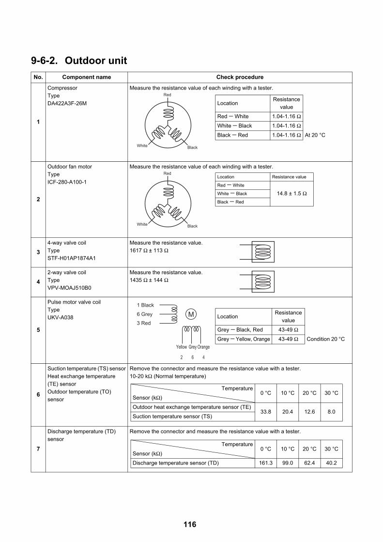
9-6-2. Outdoor unit
No. Component name Check procedure
1
Compressor
Type
DA422A3F-26M
Measure the resistance value of each winding with a tester.
2
Outdoor fan motor
Type
ICF-280-A100-1
Measure the resistance value of each winding with a tester.
3
4-way valve coil
Type
STF-H01AP1874A1
Measure the resistance value.
1617 Ω ± 113 Ω
4
2-way valve coil
Type
VPV-MOAJ510B0
Measure the resistance value.
1435 Ω ± 144 Ω
5
Pulse motor valve coil
Type
UKV-A038
6
Suction temperature (TS) sensor
Heat exchange temperature
(TE) sensor
Outdoor temperature (TO)
sensor
Remove the connector and measure the resistance value with a tester.
10-20 kΩ (Normal temperature)
7
Discharge temperature (TD)
sensor
Remove the connector and measure the resistance value with a tester.
Red
White Black
LocationResistance
value
Red − White 1.04-1.16 Ω
White − Black 1.04-1.16 Ω
Black − Red 1.04-1.16 Ω At 20 °C
Red
White Black
Location Resistance value
Red − White
14.8 ± 1.5 ΩWhite − Black
Black − Red
M1 Black
6 Grey
3 Red
Yellow
2
Grey
6
Orange
4
LocationResistance
value
Grey − Black, Red 43-49 Ω
Grey − Yellow, Orange 43-49 Ω Condition 20 °C
Temperature0 °C 10 °C 20 °C 30 °C
Sensor (kΩ)
Outdoor heat exchange temperature sensor (TE)33.8 20.4 12.6 8.0
Suction temperature sensor (TS)
Temperature0 °C 10 °C 20 °C 30 °C
Sensor (kΩ)
Discharge temperature sensor (TD) 161.3 99.0 62.4 40.2
116
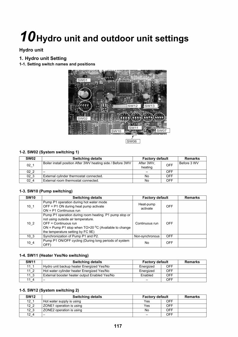
10Hydro unit and outdoor unit settingsHydro unit
1. Hydro unit Setting1-1. Setting switch names and positions
1-2. SW02 (System switching 1)
1-3. SW10 (Pump switching)
1-4. SW11 (Heater Yes/No switching)
1-5. SW12 (System switching 2)
SW02 Switching details Factory default Remarks
02_1Boiler install position After 3WV heating side / Before 3WV After 3WV,
heatingOFF
Before 3 WV
02_2 – – OFF02_3 External cylinder thermostat connected. No OFF02_4 External room thermostat connected. No OFF
SW10 Switching details Factory default Remarks
10_1Pump P1 operation during hot water modeOFF = P1 ON during heat pump activateON = P1 Continuous run
Heat-pump activate
OFF
10_2
Pump P1 operation during room heating. P1 pump stop or not using outside air temperature.OFF = Continuous runON = Pump P1 stop when TO>20 oC (Available to change the temperature setting by FC 9E)
Continuous run OFF
10_3 Synchronization of Pump P1 and P2. Non-synchronous OFF
10_4Pump P1 ON/OFF cycling (During long periods of system OFF)
No OFF
SW11 Switching details Factory default Remarks11_1 Hydro unit backup heater Energized Yes/No Energized OFF11_2 Hot water cylinder heater Energized Yes/No Energized OFF11_3 External booster heater output Enabled Yes/No Enabled OFF11_4 – – OFF
SW12 Switching details Factory default Remarks12_1 Hot water supply is using Yes OFF12_2 ZONE1 operation is using Yes OFF12_3 ZONE2 operation is using No OFF12_4 – – OFF
SW10
SW01
SW02
SW11
SW12
SW06
SW13
SW07
117

1-6. SW13 (System switching 3)
2. Function Code Setting• Hydro unit function code setting is available only for the header remote controller.• Set function codes for various operation modes with the remote controller.
2-1. How to set hydro unit function code<Procedure> Perform the following when no operation is in progress.
SW13 Switching details Factory default Remarks13_1 3WV SPST/SPSD Specification switching SPST OFF13_2 Boiler output enabled No OFF13_3 Auto Restart of power outage after system power failure. Yes OFF13_4 – – ON
1 Press the [ ] button and the [ ] button at same time for 4 seconds or longer on the top screen to display the “FIELD SETTING MENU”.
2 Press the [ ] / [ ] button to select “FC for Hydro unit” on the FIELD SETTING screen, then press the [ ] button.
3 Press the [ ] / [ ] button to select FC number or Data, then press the [ ] / [ ] button to set the value.
4 Press the [ ] button. The set value is registered.
FIELD SETTING MENU(2/2)FC for Hydro unit
FC for Remote controller
SET
FC for Hydro unit
FC No. Data
FIX
0001
118
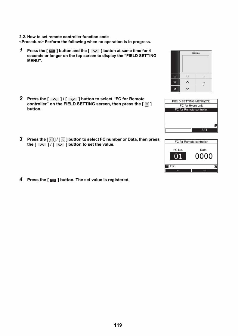
2-2. How to set remote controller function code<Procedure> Perform the following when no operation is in progress.
1 Press the [ ] button and the [ ] button at same time for 4 seconds or longer on the top screen to display the “FIELD SETTING MENU”.
2 Press the [ ] / [ ] button to select “FC for Remote controller” on the FIELD SETTING screen, then press the [ ] button.
3 Press the [ ] / [ ] button to select FC number or Data, then press the [ ] / [ ] button to set the value.
4 Press the [ ] button. The set value is registered.
FIELD SETTING MENU(2/2)
FC for Hydro unitFC for Remote controller
SET
FC for Remote controller
FC No. Data
FIX
0000
119
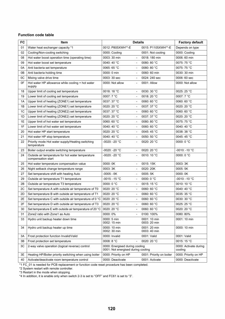
Function code table
FC Item Details Factory default
01 Water heat exchanger capacity *1 0012: P805XWH**-E 0015: P1105XWH**-E Depends on type
02 Cooling/Non-cooling switching 0000: Cooling 0001: Not cooling 0000: Cooling
08 Hot water boost operation time (operating time) 0003: 30 min - 0018: 180 min 0006: 60 min
09 Hot water boost set temperature 0040: 40 °C - 0080: 80 °C 0075: 75 °C
0A Anti bacteria set temperature 0065: 65 °C - 0080: 80 °C 0075: 75 °C
0B Anti bacteria holding time 0000: 0 min - 0060: 60 min 0030: 30 min
0C Mixing valve drive time 0003: 30 sec - 0024: 240 sec 0006: 60 sec
0F Hot water HP allowance while cooling + hot water supply
0000: Not allow - 0001: Allow 0000: Not allow
18 Upper limit of cooling set temperature 0018: 18 °C - 0030: 30 °C 0025: 25 °C
19 Lower limit of cooling set temperature 0007: 7 °C - 0018: 20 °C 0007: 7 °C
1A Upper limit of heating (ZONE1) set temperature 0037: 37 °C - 0060: 60 °C 0060: 60 °C
1B Lower limit of heating (ZONE1) set temperature 0020: 20 °C - 0037: 37 °C 0020: 20 °C
1C Upper limit of heating (ZONE2) set temperature 0037: 37 °C - 0060: 60 °C 0060: 60 °C
1D Lower limit of heating (ZONE2) set temperature 0020: 20 °C - 0037: 37 °C 0020: 20 °C
1E Upper limit of hot water set temperature 0060: 60 °C - 0080: 80 °C 0075: 75 °C
1F Lower limit of hot water set temperature 0040: 40 °C - 0060: 60 °C 0040: 40 °C
20 Hot water HP start temperature 0020: 20 °C - 0045: 45 °C 0038: 38 °C
21 Hot water HP stop temperature 0040: 40 °C - 0050: 50 °C 0045: 45 °C
22 Priority mode Hot water supply/Heating switching temperature
-0020: -20 °C - 0020: 20 °C 0000: 0 °C
23 Boiler output enable switching temperature -0020: -20 °C - 0020: 20 °C -0010: -10 °C
24 Outside air temperature for hot water temperature compensation start
-0020: -20 °C - 0010: 10 °C 0000: 0 °C
25 Hot water temperature compensation value 0000: 0K - 0015: 15K 0003: 3K
26 Night setback change temperature range 0003: 3K - 0020: 20K 0005: 5K
27 Set temperature shift with heating Auto -0005: -5K - 0005: 5K 0000: 0K
29 Outside air temperature T1 temperature -0015: -15 °C - 0000: 0 °C -0010: -10 °C
2B Outside air temperature T3 temperature 0000: 0 °C - 0015: 15 °C 0010: 10 °C
2C Set temperature A with outside air temperature of T0 0020: 20 °C - 0060: 60 °C 0040: 40 °C
2D Set temperature B with outside air temperature of T1 0020: 20 °C - 0060: 60 °C 0035: 35 °C
2E Set temperature C with outside air temperature of 0 °C 0020: 20 °C - 0060: 60 °C 0030: 30 °C
2F Set temperature D with outside air temperature of T3 0020: 20 °C - 0060: 60 °C 0025: 25 °C
30 Set temperature E with outside air temperature of 20 °C 0020: 20 °C - 0060: 60 °C 0020: 20 °C
31 Zone2 ratio with Zone1 as Auto 0000: 0% - 0100: 100% 0080: 80%
33 Hydro unit backup heater down time 0000: 5 min0002: 15 min
0001: 10 min0003: 20 min
0001: 10 min
34 Hydro unit backup heater up time 0000: 10 min0002: 30 min
0001: 20 min0003: 40 min
0000: 10 min
3A Frost protection function Invalid/Valid 0000: Invalid 0001: Valid 0001: Valid
3B Frost protection set temperature 0008: 8 °C - 0020: 20 °C 0015: 15 °C
3C 2-way valve operation (logical reverse) control 0000: Energised during cooling0001: Not energised during cooling
0000: Activate during cooling
3E Heating HP/Boiler priority switching when using boiler 0000: Priority on HP 0001: Priority on boiler 0000: Priority on HP
40 Activate/deactivate room temperature control 0000: Deactivate 0001: Activate 0000: Deactivate
*1 FC_01 is needed for PCB replacement or function code reset procedure has been completed.*2 System restart with remote controller.*3 Restart in the mode when stopping.*4 In addition, it is enable only when switch 2-3 is set to “OFF” and FC61 is set to “3”.
120

52 External input contact logic (must be used in with FC61)
0000: CLOSE to stop system *20001: OPEN to stop system *20002: OPEN to stop system, CLOSE to restart system (Statics input)0003: CLOSE to stop system, CLOSE again to restart system (plus input)
0000:CLOSE to stop
54 Logic of 3-way valve’s action when powered (Single return only)
0000: Not reversed (Hot water mode when powered)0001: Reversed (Heating when powered)
0000: Not reversed(Hot water mode when powered)
58 Night setback is activated 0000: Zone 1 & 20001: Zone 1 only
0000: Zone1 & 2
59 Interval of Mixing Valve control 0001: 1 minute - 0030: 30 minutes 0004: 4 minutes
5A P1 setting while in hot water supply mode 0000: While running HP only0001: P1 continues running
0000: While running HP only
5B Boiler running setting 0000: Boiler and HP0001: Boiler only with pump running0002: Heater0003: Boiler only (Pump stopping)
0003: Boiler only
61 Changing the target of stopping/starting by external signal or changing the TEMPO setting
0000: Hot water supply and heating0001: Keeping initial status *30002: Hot water supply only0003: Heating only0004: TEMPO1 (Not activate the heaters)0005: TEMPO2 (Not activate the heaters, inlet pump, heat pump)
0000: Hot water supply and heating
62 Activate/deactivate A02 error detection 0000: Activate0001: Deactivate
0000: Activate
64 Continuously run or stop the P2 pump while cooling 0000: Continuously run P20001: Stop P2
0000: Continuous running
65 P1 pump setting when the thermostat is deactivated in the room temperature remote controller and room temperature thermostat settings
0000: Continuously run P10001: Stop P1 when the thermostat is OFF
0000: Continuous running
67 Changing the condition of optional output (For the optional PC board connected to CN209)
0000: 1-3 During defrosting2-3 While compressor is running.0001: 1-3 As error is detected2-3 During operation
0000: 1-3 During defrosting2-3 While compressor is running.
6E To diff temperature, when pump P1 stop at to 20 °C 0001: 1K 0005: 5K 0002: 2K
73 Hot water tank heater start time of heat-pump while operating
0000: 30 min passed 0003: 120 min passed 0000: 30 min passed
92 Upper room temperature limit when cooling 0000: 0 °C - 0055: 55 °C 0029: 29 °C
93 Lower room temperature limit when cooling 0000: 0 °C - 0055: 55 °C 0018: 18 °C
94 Upper room temperature limit when heating 0000: 0 °C - 0055: 55 °C 0029: 29 °C
95 Lower room temperature limit when heating 0000: 0 °C - 0055: 55 °C 0018: 18 °C
96 Initial water temperature setting when controlling cooling by the room temperature remote controller and room temperature thermostat
0005: 5 °C - 0030: 30 °C 0020: 20 °C
9D Initial water temperature setting when controlling heating by the room temperature remote controller and room temperature thermostat
0020: 20 °C - 0060: 60 °C 0040: 40 °C
9E TO temperature setting to stop the P1 pump during the middle period heating
0010: 10 °C - 0030: 30 °C 0020: 20 °C
A0 P1 pump speed control changes the percentage duty of the PWM control
0000: 100% 0005: 50% 0000: 100%
A1 Outside air temperature T0 temperature -0030: -30 °C - -0020: -20 °C -0020: -20 °C
A2 Zone2 temperature setting method 0000: Percentage (FC31)0001: Fixed value (FCA3~ A5)
0000: Percentage
A3 Set temperature A' with outside temperature of T0 0020: 20 °C - 0060: 60 °C 0040: 40 °C
A4 Set temperature B' with outside temperature of T1 0020: 20 °C - 0060: 60 °C 0035: 35 °C
FC Item Details Factory default
*1 FC_01 is needed for PCB replacement or function code reset procedure has been completed.*2 System restart with remote controller.*3 Restart in the mode when stopping.*4 In addition, it is enable only when switch 2-3 is set to “OFF” and FC61 is set to “3”.
121

Remote controller function code table
*14~1A: for floor drying function
A5 Set temperature E' with outside temperature of 20 °C 0020: 20 °C - 0060: 60 °C 0020: 20 °C
B2 HP restart water temperature in A zone. (Valid only room temp control using 2nd remote controller)
0020: 20 °C 0037: 37 °C 0025: 25 °C
B5 Initial water temperature setting method when controlling heating by the room temperature remote controller and room temperature thermostat
0000: The fixed temperature by FC9D0001: The calculated temperature by Auto curve
0000: The fixed
B6 Changing the target of stopping / starting by external signal (CN210 - terminal 2 and 3)
0000: none (Local hot water tank thermostat)0001: Hot water supply control *4
0000: none
B8 Forcibly heater off at T0 ≥ A °C 0000: no restriction, 0001: 20 °C0002: 15 °C, ···, 0006: -5 °C
0000: no restriction
B9 Backup heater energization temperature during defrosting.
Correction coefficient B0000: 0K, ···, 0004: 40K
0000: 0K
BA Intermittent operation at T0 ≥ A °C(heating mode)
0000: continuous operation0001: 20 °C, ···, 0006: -5 °C
0000: continuous operation
BB Intermittent operation at T0 < B °C(cooling mode)
0000: continuous operation0001: 35 °C, ···, 0003: 25 °C
0000: continuous operation
BC Pump off time during thermostat off operation 0000: 5 min, ···, 0005: 30 min 0001: 10 min
FC Item Details Fist shipment
02 Temperature correction by the room temperature sensor (heating)
-10K~+10K: By 1K steps -1: -1K correction
03 Temperature correction by the room temperature sensor (cooling)
-10K~+10K: By 1K steps -1: -1K correction
05 24H/12H display switching 0: 24H display 1: 12H (AM/PM) display 0: 24H display
09 Night time low-noise mode 0: Invalid 1: Valid 0: Invalid
0A Night time low-noise start time 0 - 23 (0:00 to 23:00) 22: 22:00
0B Night time low-noise end time 0 - 23 (0:00 to 23:00) 06: 06:00
0C Anti bacteria start time 0 - 23 (0:00 to 23:00) 22: 22:00
0D Anti bacteria start cycle 1 - 10 (Every day to 10-day cycle) 07: 7-day cycle
0E Starting time of Night setback 0 - 23 (0:00 to 23:00) 22: 22:00
0F Ending time of Night setback 0 - 23 (0:00 to 23:00) 06: 06:00
11 Remote controller Alarm Tone. 0: Alarm Tone OFF 1: Alarm Tone ON 1: Alarm Tone ON
12 Frost running period (days) (0 days – 20 days) 00: No setting
13 Frost running period (hours) (0 hours – 23 hours) 00: No setting
14 Start and End temperature 20 - 55 (20 °C - 55 °C) 00: No setting
15 Max temperature 20 - 55 (20 °C - 55 °C) 00: No setting
16 Continuation days for every step up to Max temperature 1 - 7 (1 day - 7 days) 00: No setting
17 Temperature difference for every step up to Max temperature
1 - 10 (1 K - 10 K) 00: No setting
18 Continuation days for every step down to End temperature
1 - 7 (1 day - 7 days) 00: No setting
19 Temperature difference for every step down to End temperature
1 - 10 (1 K - 10 K) 00: No setting
1A Continuation days in Max temperature 1 - 30 (1 day - 30 days) 00: No setting
FC Item Details Factory default
*1 FC_01 is needed for PCB replacement or function code reset procedure has been completed.*2 System restart with remote controller.*3 Restart in the mode when stopping.*4 In addition, it is enable only when switch 2-3 is set to “OFF” and FC61 is set to “3”.
122

2-3. How to reset hydro function codeIf the hydro unit PCB has been replaced, it is necessary to change the FC 01 (capacity setting)(1) Preparation
1) Turn all off the Hot water supply operation and Heating/Cooling operation.
2) Turn off the power supply of the hydro unit and the outdoor unit.
3) Remove the front panel of the hydro unit and cover to the hydro unit electrical box.
4) Set SW06_1 and _2 "ON".
(2) Procedure
1) Turn on the power supply of the hydro unit and the outdoor unit.
• The small yellow LED located near the MCU should be flashing slowly.
2) Press tactile switch SW07 until the yellow LED turns off.• When the tactile switch SW07 has been press for 5 sec, flashing becomes quickly. And when the
switch will be pressed further 5 sec, the yellow LED will turn off.When the SW07 is released, the yellow LED start to flash quickly again.
3) Turn off the power supply of the hydro unit and the outdoor unit.
4) Set SW06_1 and _2 to "OFF".
5) Replace the electrical box cover and front panel on the hydro unit.
2-4. How to reset remote controller function codeYou can reset remote controller function code on remote controller. Press the [ ] [ ] [ ] long time in “FC for remote controller” display, and select “YES”.
SW06 SW07
Yellow LEDAnd you can reset hydro function code on remote controller. Press the [ ] [ ] [ ] long time in “FC for Hydro unit” display, and select “YES”.
123

3. Test run• Even if the outside air temperature or water temperature is outside the setting value range, Heating, Cooling and
Hot water supply operation become possible.• Since the protection setting is disabled in the TEST mode, do not continue a test run longer than 10 minutes.
<Procedure>
• The pump is activated in 30 seconds. If air is not released completely, the flow rate switch is activated to stop operation. Release air again according to the piping procedure. Little air entrainment is discharged from the purge valve.
• Check that the hydraulic pressure has become the predetermined pressure 0.1 to 0.2 MPa (1 to 2 bar). If the hydraulic pressure is insufficient, replenish water.
• Heating operation starts. Check that the hydro unit starts heating.• Press the [ ] button to select the Cooling operation, in a few second, the operation starts.• Check that the hydro unit starts cooling and that the floor heating system is not cooled.• Press the [ ] button to stop the operation.• Press the [ ] button to start the Hot water supply operation.• Check that there is no air entrainment.• Check that hot water is present at the connection port of the hot water cylinder.• Press the [ ] button or [ ON/OFF] button to stop the operation.
1 Press the [ ] button and the [ ] button at same time for 4 seconds or longer on the top screen to display the “FIELD SETTING MENU”.
2 Press the [ ] / [ ] button to select “Test mode” on the FIELD SETTING MENU screen, then press the [ ] button.
3 Press the [ ] button to select ON, then press the [ ] button. The mark appears on the top screen.
4 Start the heating or cooling or Hot water operation on the top screen, then the selected mode mark is blinking during Test mode.
Test modeFIELD SETTING MENU(1/2)
Floor dryingForced defrostingInformation input
SET
Alarm history
Test mode
ONOFF
FIX
ZONE1 ZONE2 HOT WATER
HEAT/COOL HOT WATER
MON
124

4. Auto Curve Setting• This function is available only for the header remote controller.• Set function codes for various operation modes with the remote controller.
<Procedure> Perform the following when no operation is in progress.
1 Press the [ ] button and the [ ] button at same time for 4 seconds or longer on the top screen to display the “FIELD SETTING MENU”.
2 Press the [ ] / [ ] button to select “FC for Hydro unit” on the FIELD SETTING screen, then press the [ ] button.
3 Press the [ ] / [ ] button to select FC number or Data, then press the [ ] / [ ] button to set the value.
4 Press the [ ] button. The set value is registered.
FIELD SETTING MENU(2/2)FC for Hydro unit
FC for Remote controller
SET
FC for Hydro unit
FC No. Data
FIX
0001
125

<ZONE1>• An operation starts at the set temperature of straight -line approximation for the following: water temperature A °C with the outside
temperature T0 °C, B °C with T1 °C, C °C with T2 °C, D °C with T3 °C, and E °C with 20 °C.
<ZONE2>• Set temperature of the ZONE2 can be selected from two methods (FC_A2). One is a percentage of ZONE1, the other is a fixed value.FC_A2 = "0" : Percentage method that is set by FC_31.FC_A2 = "1" : Fixed value method that is set by FC_A3, A4 and A5.
However, it is automatically controlled the set temperature of ZONE1 to be the ZONE2 or more.
TSC_F(°C)
A(40)
B(35)
C(30)
D(25)
E(20)
T0(-20)
T2=0 20 TOT1(-10)
T3(10)
± 5K adjustable (FC 27)
(°C)
Related FCFC No. Setting item Default range
2C Setting temperature A at T0 40 20~60 °C
2D Setting temperature B at T1 35 20~60 °C
2E Setting temperature C at T2(= 0 °C) 30 20~60 °C
2F Setting temperature D at T3 25 20~60 °C
30 Setting temperature E at 20 °C 20 20~60 °C
A1 Outside temperature T0 -20 -30~-20 °C
29 Outside temperature T1 -10 -15~0 °C
2B Outside temperature T3 10 0~15 °C
27 Set temperature shift with heating set to auto 0 -5 to 5K
TSC_F(°C)
A'(40)
B'(35)
E'(20)
T0(-20)
20 TO (°C)T1(-10)
FC_A2=1 Fixed value method
TSC_F(°C)
A(40)
B(35)
C(30)
D(25)
E(20)
T0(-20)
T2=0 20 TO (°C)T1(-10)
T3(10)
ZONE 1
ZONE 280 % (FC_31) of ZONE1
FC_A2=0 Percentage method
Auto-Curve in ZONE2 shows 80% (FC) of that of ZONE1, the water temperature setting does not fall below 20 °C.
The ZONE2 set temperature A' °C with the outside temperature T0 °C, B' °C with T1 °C, E' °C with 20 °C.
Related FCFC No. Setting item Default range
A2 The choice of how to set ZONE2 0 0 or 1
A3 Setting temperature A' at T0 40 20~60 °C
A4 Setting temperature B' at T1 35 20~60 °C
A5 Setting temperature E' at 20 °C 20 20~60 °C
31 Auto-Curve ratio of ZONE2 80 0~100%
126

Auto-Curve temperature shift• This function is available only for the header remote controller. • The set temperature can be shifted in the range of ±5K of the current setting.
1 Press the [ ] / [ ] button to select “Auto mode” on the MENU screen.
2 Press the [ ] button for 4 seconds or longer to enter the setting mode. The function code setting screen appears.FC No. 27: Shifted temperature (Range: -5 ~ +5, Default: 0)
3 Press the [ ] button to select Data value, then press the [ ] / [ ] button to adjust the temperature between -5K to +5 K.
4 Press the [ ] button. The set temperature is registered.
Auto modeMENU(1/2)
Schedule timerNight setbackSilent mode
Hot water boost
SET
Auto mode
FC No. Data
FIX
127

5. Clock Setting• Setting for the clock (date, month, year, time)
1 Press the [ ] / [ ] button to select “Setting” on the MENU screen, then press the [ ] button.
2 Press the [ ] / [ ] button to select “Initial setting” on the Setting screen, then press the [ ] button.
3 Press the [ ] / [ ] button to select “Clock” on the Initial setting screen, then press the [ ] button.
4 Press the [ ] / [ ] button to select the date, month, year, and, time.
5 Press the [ ] / [ ] button to set the value, then press the [ ] button.• The clock display appears on the top screen.• The clock display blinks if the clock setting has been reset due to power
failure or other cause.
Anti bacteriaMENU(2/2)
Frost protection
Setting
Information
SET
Initial setting
Setting
Schedule setting
SET
ClockInitial setting(1/2)
Screen contrastBacklight
Header / Second
SET
Temperature control
← →
31 / 12 / 2016 01:11
Clock
FIX
128

6. Scheduled Operation Setting6-1. How to set scheduled operation• This function is available only for the header remote controller. • Schedule setting makes the following modes to be flexibly set: hot water supply, heating, cooling, hot water
supply and heating, hot water supply and cooling, and stop, and set temperature.• Set the unit clock and the schedule condition setting before schedule timer setting.
<Preparation>Set the remote controller time at first.
Condition setting• Up to 6 different running patterns per day can be programmed.
1 Press the [ ] / [ ] button to select “Setting” on the MENU screen, then press the [ ] button.
2 Press the [ ] / [ ] button to select “Schedule setting” on the setting screen, then press the [ ] button.
1 Press the [ ] / [ ] button to select “Condition setting” on the Schedule setting screen, then press the [ ] button.
2 Press the [ ] button to select the day, then press the [ ] button to input running pattern.
3 Press [ ] / [ ] button to select the change item, then press the [ ] / [ ] button.
Anti bacteriaMENU(2/2)
Frost protection
Setting
Information
SET
Initial setting
Setting
Schedule setting
SET
Condition setting
Schedule setting
Holiday setting
SET
Key lock
- - - - - - - - - - : - - - - : - -
- - - - - - - - - - : - - - - : - - - - - - - - - - - - : - - - - : - -
Condition setting(1/2)
ALL TUE WED THU FRI SAT SUN
Mode Start End
SETDAYCOPY RESET
Z1 Z2 HW
MON
55 45 - - 08:00 22:0025 - - - - 23:00 - - : - -- - - - 65 18:00 19:00
Condition setting(1/2)
FIX RESET
COOL
HW
HEAT
ALL TUE WED THU FRI SAT SUN
Mode Start EndZ1 Z2 HW
MON
129

4 Press the [ ] button.
5 Press the [ ] button to Fix.Mode :Operation mode (HEAT, COOL, HW (Hot water)) Z1 :ZONE1 setting temperatureZ2 :ZONE2 setting temperatureHW :Hot water supply operation setting temperatureStart :Operation start time (0:00 ~ 23:59)End :Operation end time (0:00 ~ 24:00, -- : --)• “-- : --” means the operation continues.
If End time is set earlier than Start time, an error is displayed.
Schedule timer confirm?
Condition setting
NOYES
130
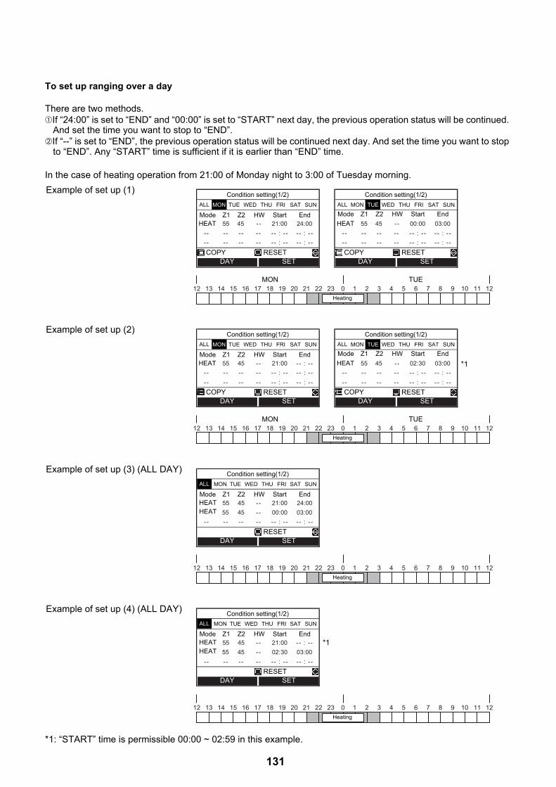
To set up ranging over a day
There are two methods.➀If “24:00” is set to “END” and “00:00” is set to “START” next day, the previous operation status will be continued.
And set the time you want to stop to “END”.➁If “--” is set to “END”, the previous operation status will be continued next day. And set the time you want to stop
to “END”. Any “START” time is sufficient if it is earlier than “END” time.
In the case of heating operation from 21:00 of Monday night to 3:00 of Tuesday morning.
*1: “START” time is permissible 00:00 ~ 02:59 in this example.
Example of set up (1)
Example of set up (2)
Example of set up (3) (ALL DAY)
Example of set up (4) (ALL DAY)
55 45 -- 21:00 24:00 - - - - - - - - - - : - - - - : - - - - - - - - - - - - : - - - - : - -
Condition setting(1/2)
COPY RESET
HEAT
ALL TUE WED THU FRI SAT SUN
Mode Start EndZ1 Z2 HW
MON
DAY SET
55 45 -- 00:00 03:00 - - - - - - - - - - : - - - - : - - - - - - - - - - - - : - - - - : - -
Condition setting(1/2)
HEAT
ALL TUE WED THU FRI SAT SUN
Mode Start EndZ1 Z2 HW
MON
COPY RESETDAY SET
12 13 14 15 16 17 18 19 20 21 22 23 2 3 4 5 6 7 8 9 10 11 120 1MON TUE
Heating
55 45 - - 21:00 - - : - - - - - - - - - - - - : - - - - : - - - - - - - - - - - - : - - - - : - -
Condition setting(1/2)
COPY RESET
HEAT
ALL TUE WED THU FRI SAT SUN
Mode Start EndZ1 Z2 HW
MON
DAY SET
55 45 -- 02:30 03:00 - - - - - - - - - - : - - - - : - - - - - - - - - - - - : - - - - : - -
Condition setting(1/2)
HEAT
ALL TUE WED THU FRI SAT SUN
Mode Start EndZ1 Z2 HW
MON
COPY RESETDAY SET
*1
12 13 14 15 16 17 18 19 20 21 22 23 2 3 4 5 6 7 8 9 10 11 120 1MON TUE
Heating
55 45 - - 21:00 24:00 55 45 - - 00:00 03:00
- - - - - - - - - - : - - - - : - -
Condition setting(1/2)
RESET
HEAT
ALL TUE WED THU FRI SAT SUN
Mode Start EndZ1 Z2 HW
MON
DAY SET
HEAT
12 13 14 15 16 17 18 19 20 21 22 23 2 3 4 5 6 7 8 9 10 11 120 1Heating
55 45 - - 21:00 - - : - - 55 45 - - 02:30 03:00
- - - - - - - - - - : - - - - : - -
Condition setting(1/2)
RESET
HEAT
ALL TUE WED THU FRI SAT SUN
Mode Start EndZ1 Z2 HW
MON
DAY SET
HEAT*1
12 13 14 15 16 17 18 19 20 21 22 23 2 3 4 5 6 7 8 9 10 11 120 1Heating
131

To copy the settings of the previous day
To reset the settings for each day.
1 Press the [ ] button to select the day, then press the [ ] button to copy the settings of the previous day.
2 Press the [ ] button, then the contents of the setting is displayed.
↓
• If the [ ] button is pressed in the state where “MON” is selected, the contents of the setting of “SUN” is copied.
1 Press the [ ] button to select the day, then press the [ ] button to reset the settings of the day.
2 Press the [ ] button, then the contents of the setting is cleared.
↓
- - - - - - - - - - : - - - - : - -
- - - - - - - - - - : - - - - : - - - - - - - - - - - - : - - - - : - -
Condition setting(1/2)
ALL TUE WED THU FRI SAT SUN
Mode Start End
SETDAYCOPY RESET
Z1 Z2 HW
MON
Copy the previous day setting?
Condition setting
NOYES
55 45 - - 08:00 22:0025 - - - - 23:00 - - : - -- - - - 65 18:00 19:00
Condition setting(1/2)
COOL
HW
HEAT
ALL TUE WED THU FRI SAT SUN
Mode Start EndZ1 Z2 HW
MON
SETDAYCOPY RESET
55 45 - - 08:00 22:0025 - - - - 23:00 - - : - -- - - - 65 18:00 19:00
Condition setting(1/2)
COOL
HW
HEAT
ALL TUE WED THU FRI SAT SUN
Mode Start EndZ1 Z2 HW
MON
SETDAYCOPY RESET
Delete the day setting?
Condition setting
NOYES
- - - - - - - - - - : - - - - : - -
- - - - - - - - - - : - - - - : - - - - - - - - - - - - : - - - - : - -
Condition setting(1/2)
ALL TUE WED THU FRI SAT SUN
Mode Start End
SETDAYCOPY RESET
Z1 Z2 HW
MON
132

Holiday setting• Set the days of the week when the schedule timer not used.
Key lock• Select whether to LOCK / UNLOCK [ON/OFF], [Temperature], [mode] during schedule timer.
To enable the Schedule timer function
1 Press the [ ] / [ ] button to select “Holiday setting” on the Schedule setting screen, then press the [ ] button.
2 Press the [ ] button to select the day, then press the [ ] button to set.●: Schedule timer is not used.
3 Press the [ ] button to Fix.
1 Press the [ ] / [ ] button to select “Key lock” on the Schedule setting screen, then press the [ ] button.
2 Press the [ ] button to select object, then press the [ ] button to select LOCK or UNLOCK.●: LOCK
3 Press the [ ] button to Fix.• When “LOCK” is selected, the key cannot be used during Key lock and schedule timer.• The factory default is “UNLOCK”.
1 Press the [ ] / [ ] button to select “Schedule timer” on the MENU screen, then press the [ ] button.
2 Press the [ ] button to select “ON” on the Schedule timer screen, then press the [ ] button. The mark appears on the top screen.
Condition setting
Schedule setting
Holiday setting
SET
Key lock
MON TUE WED FRI SAT SUN
SETDAY
THU
FIX
Holiday setting
ON/OFF
Key lock
FIX
Temp. Mode
SELECT LOCK
Auto modeMENU(1/2)
Schedule timer
Night setbackSilent mode
Hot water boost
SET
ON
Schedule timer
OFF
FIX
133

7. Frost protection Setting• This function performs operation with the minimum capacity (target water temperature:15°C) to prevent pipes
from freezing in case the unit is not used for a long period due to absence.• Cancel schedule timer to start Frost protection operation. When Frost protection is operated with schedule timer
on, it may stop during its operation.• The minimum capacity can be changed, ask the installation company to make the required changes to the
settings.• This function takes precedence over the Night setback operation that is set separately.• Start the heating operation before making the setting.
It may not be able to go to the setting screen immediately after start. In that case, select “Frost protection” again after tens of seconds.
1 Press the [ ] / [ ] button to select “Frost protection” on the MENU screen, then press the [ ] button.
2 Press the [ ] button to select “ON” on the Frost protection screen, then press the [ ] button.
3 The temperature indication change to “F” and mark appears on the top screen.• When the set period has passed, the Frost protection operation ends
automatically.
MENU(2/2)
Frost protection
SettingInformation
SET
Anti bacteria
ON
Frost protection
OFF
FIX
ZONE1 HOT WATER
HEAT/COOL HOT WATER
MON
134
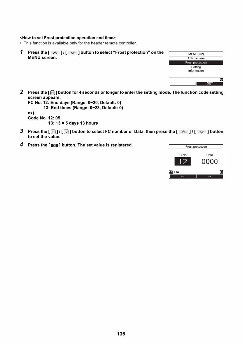
<How to set Frost protection operation end time>• This function is available only for the header remote controller.
1 Press the [ ] / [ ] button to select “Frost protection” on the MENU screen.
2 Press the [ ] button for 4 seconds or longer to enter the setting mode. The function code setting screen appears.FC No. 12: End days (Range: 0~20, Default: 0) 13: End times (Range: 0~23, Default: 0)ex) Code No. 12: 05 13: 13 = 5 days 13 hours
3 Press the [ ] / [ ] button to select FC number or Data, then press the [ ] / [ ] button to set the value.
4 Press the [ ] button. The set value is registered.
MENU(2/2)
Frost protection
SettingInformation
SET
Anti bacteria
Frost protection
FC No. Data
FIX
135

8. NIGHT Operation Setting• This function is used for energy saving during specified time zone (sleeping hours, etc.).• For night time hours (sleeping hours, etc.), this function shifts the set temperature of heating or cooling by 5K.
<How to set NIGHT operation start and end time>• This function is available only for the header remote controller.
1 Press the [ ] / [ ] button to select an “Night setback” on the MENU screen, then press the [ ] button.
2 Press the [ ] button to select “ON” on the Night setback screen, then press the [ ] button.
3 Start the heating or cooling operation, then the mark appears on the top screen.
1 Press the [ ] / [ ] button to select an “Night setback” on the MENU screen.
2 Press the [ ] button for 4 seconds or longer to enter the setting mode. The function code setting screen appears. FC No. 0E: Start time (Range: 0~23, Default: 22) 0F: End time (Range: 0~23, Default: 06)
3 Press the [ ] / [ ] button to select FC number or Data, then press the [ ] / [ ] button to set the value. The same value cannot be set to 0E and 0F.
4 Press the [ ] button. The set time is registered.
Auto modeMENU(1/2)
Schedule timer
Night setback
Silent modeHot water boost
SET
ON
Night setback
OFF
FIX
Auto modeMENU(1/2)
Schedule timer
Night setback
Silent modeHot water boost
SET
Night setback
FC No. Data
FIX
136

9. Anti bacteria Setting• This setting regularly raises the hot water cylinder temperature to prevent bacteria from growing.• The Anti bacteria operation is performed to maintain the temperature (75°C) for the period (30 minutes) when
the preset start time (22:00) comes according to the preset cycle (7 days).• The maintain temperature and the period can be changed, ask the installation company to make the required
changes to the settings.
<How to set Anti bacteria temperature and holding time>In FC_0A or 0B, the set temperature and holding time can be changed.FC_0A: Set temperature change range 70 to 80 °C (75 °C: default)FC_0B: Holding time change range 0 to 60 minutes (30 minutes: default)
<How to set Anti bacteria start time and cycle>• This function is available only for the header remote controller.
1 Press the [ ] / [ ] button to select “Anti bacteria” on the MENU screen, then press the [ ] button.
2 Press the [ ] button to select “ON” on the Anti bacteria screen, then press the [ ] button.
3 Start the hot water operation, then the mark appears on the top screen.
1 Press the [ ] / [ ] button to select “Anti bacteria” on the MENU screen.
2 Press the [ ] button for 4 seconds or longer to enter the setting mode. The function code setting screen appears.FC No. 0C: Start time (Range: 0~23, Default: 22) 0D: cycle (Range: 0~10, Default: 07)
3 Press the [ ] / [ ] button to select FC number or Data, then press the [ ] / [ ] button to set the value.
4 Press the [ ] button. The set value is registered.
Anti bacteriaMENU(2/2)
Frost protectionSetting
Information
SET
ON
Anti bacteria
OFF
FIX
Anti bacteriaMENU(2/2)
Frost protectionSetting
Information
SET
Anti bacteria
FC No. Data
FIX
137
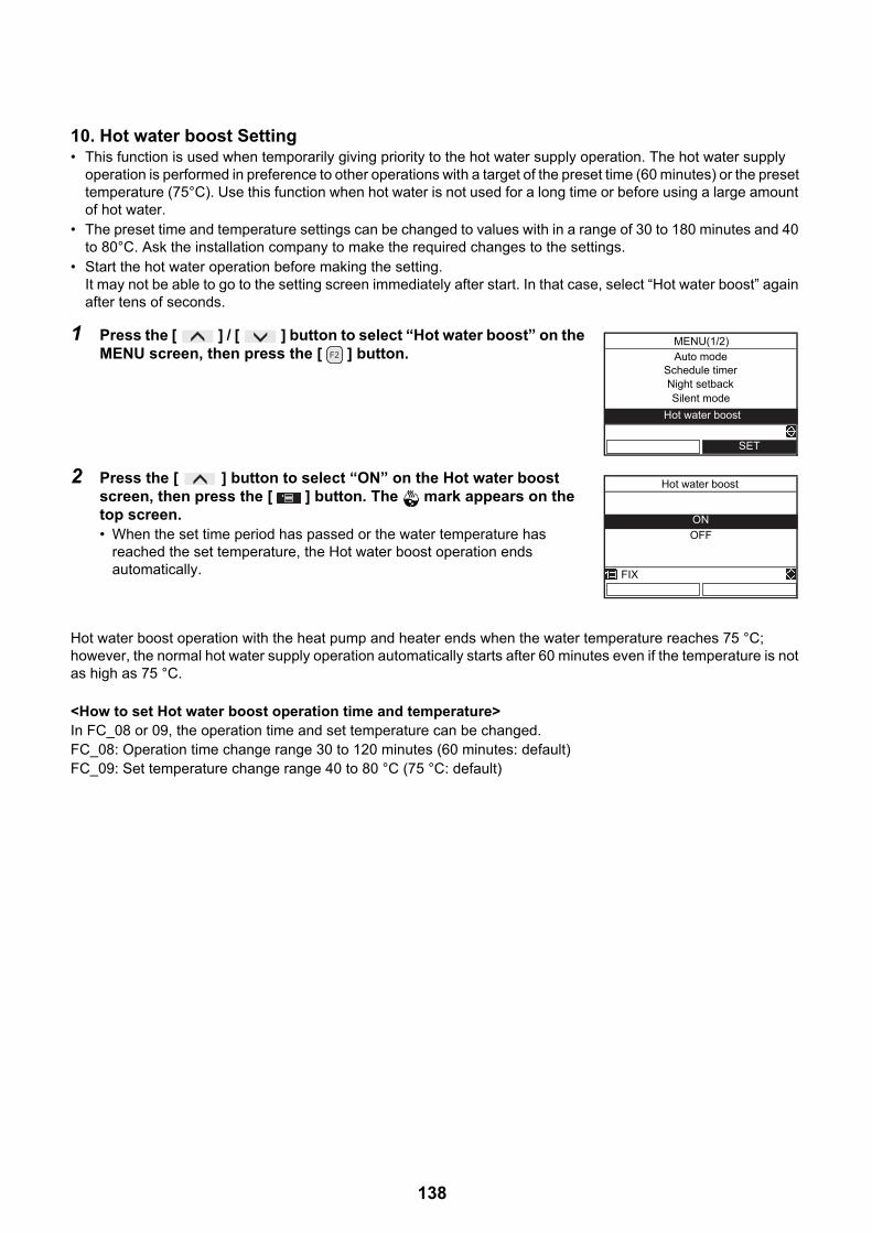
10. Hot water boost Setting• This function is used when temporarily giving priority to the hot water supply operation. The hot water supply
operation is performed in preference to other operations with a target of the preset time (60 minutes) or the preset temperature (75°C). Use this function when hot water is not used for a long time or before using a large amount of hot water.
• The preset time and temperature settings can be changed to values with in a range of 30 to 180 minutes and 40 to 80°C. Ask the installation company to make the required changes to the settings.
• Start the hot water operation before making the setting. It may not be able to go to the setting screen immediately after start. In that case, select “Hot water boost” again after tens of seconds.
Hot water boost operation with the heat pump and heater ends when the water temperature reaches 75 °C; however, the normal hot water supply operation automatically starts after 60 minutes even if the temperature is not as high as 75 °C.
<How to set Hot water boost operation time and temperature>In FC_08 or 09, the operation time and set temperature can be changed.FC_08: Operation time change range 30 to 120 minutes (60 minutes: default)FC_09: Set temperature change range 40 to 80 °C (75 °C: default)
1 Press the [ ] / [ ] button to select “Hot water boost” on the MENU screen, then press the [ ] button.
2 Press the [ ] button to select “ON” on the Hot water boost screen, then press the [ ] button. The mark appears on the top screen.• When the set time period has passed or the water temperature has
reached the set temperature, the Hot water boost operation ends automatically.
Auto modeMENU(1/2)
Night setbackSilent mode
Hot water boost
SET
Schedule timer
ON
Hot water boost
OFF
FIX
138
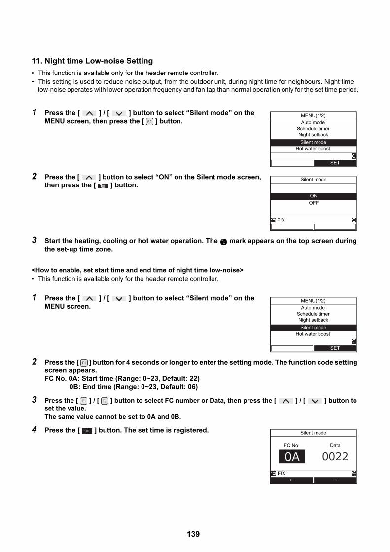
11. Night time Low-noise Setting
• This function is available only for the header remote controller.• This setting is used to reduce noise output, from the outdoor unit, during night time for neighbours. Night time
low-noise operates with lower operation frequency and fan tap than normal operation only for the set time period.
<How to enable, set start time and end time of night time low-noise>• This function is available only for the header remote controller.
1 Press the [ ] / [ ] button to select “Silent mode” on the MENU screen, then press the [ ] button.
2 Press the [ ] button to select “ON” on the Silent mode screen, then press the [ ] button.
3 Start the heating, cooling or hot water operation. The mark appears on the top screen during the set-up time zone.
1 Press the [ ] / [ ] button to select “Silent mode” on the MENU screen.
2 Press the [ ] button for 4 seconds or longer to enter the setting mode. The function code setting screen appears. FC No. 0A: Start time (Range: 0~23, Default: 22) 0B: End time (Range: 0~23, Default: 06)
3 Press the [ ] / [ ] button to select FC number or Data, then press the [ ] / [ ] button to set the value. The same value cannot be set to 0A and 0B.
4 Press the [ ] button. The set time is registered.
Auto modeMENU(1/2)
Schedule timerNight setback
Silent modeHot water boost
SET
ON
Silent mode
OFF
FIX
Auto modeMENU(1/2)
Schedule timerNight setback
Silent modeHot water boost
SET
Silent mode
FC No. Data
FIX
139

12. Forced Defrosting Setting• This function is available only for the header remote controller.• This function can active the forced defrosting mode for the outdoor unit.
(Operation)• Press the button.• Set the operation to the heating mode.• After a while, forced defrosting signals are transmitted to the outdoor unit, and the unit starts defrosting.
(Forced defrosting lasts for up to 10 minutes.)• After the defrosting, the heating operation starts.• To perform defrosting again, start with 1 above.
(Performing the forced defrosting once cancels the forced defrosting setting above described.)
1 Press the [ ] button and the [ ] button at same time for 4 seconds or longer on the top screen to display the “FIELD SETTING MENU”.
2 Press the [ ] / [ ] button to select “Forced defrosting” on the FIELD SETTING screen, then press the [ ] button.
3 Press the [ ] button to select ON, then press the [ ] button.
4 Start the heating operation on the top screen.
Test modeFIELD SETTING MENU(1/2)
Floor drying
Forced defrostingInformation input
Alarm history
SET
Forced defrosting
ONOFF
FIX
140
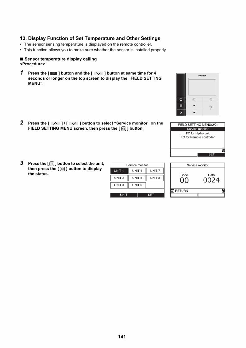
13. Display Function of Set Temperature and Other Settings• The sensor sensing temperature is displayed on the remote controller.• This function allows you to make sure whether the sensor is installed properly.
■ Sensor temperature display calling<Procedure>
1 Press the [ ] button and the [ ] button at same time for 4 seconds or longer on the top screen to display the “FIELD SETTING MENU”.
2 Press the [ ] / [ ] button to select “Service monitor” on the FIELD SETTING MENU screen, then press the [ ] button.
3 Press the [ ] button to select the unit, then press the [ ] button to display the status.
Service monitorFIELD SETTING MENU(2/2)
FC for Hydro unitFC for Remote controller
SET
Service monitor
UNIT 1 UNIT 4
UNIT 2
UNIT 3
UNIT 5
UNIT 6
UNIT 7
UNIT 8
SETUNIT
Service monitor
Code Data
RETURN
141

• Some sensors (temperature / pressure) or fan are not displayed, because not connected.
Hyd
ro u
nit d
ata
Item code Data name Unit00 Control temperature (Hot water cylinder) °C01 Control temperature (Zone1) °C02 Control temperature (Zone2) °C03 Remote controller sensor temperature °C04 Condensed temperature (TC) °C06 Water inlet temperature (TWI) °C07 Water outlet temperature (TWO) °C08 Water heater outlet temperature (THO) °C09 Floor inlet temperature (TFI) °C0A Hot water cylinder temperature (TTW) °C0B Mixing valve position step0 Low pressure (Ps) × 1/10 kPa
0F Hydro soft Ver. ‒
Out
door
uni
t da
ta
Item code Data name Unit60 Heat exchange temperature (TE) °C61 Outside air temperature (TO) °C62 Discharge temperature (TD) °C63 Suction temperature (TS) °C65 Heat sink temperature (THS) °C6A Current × 10 A6D Heat exchanger coil temperature (TL) °C70 Compressor operation Hz Hz72 Number of revolutions of outdoor fan (lower or 1 fan model) rpm73 Number of revolutions of outdoor fan (upper) rpm74 Outdoor PMV position × 1/10 pls
Ser
vice
dat
a
Item code Data name UnitF0 Micro computer energized accumulation time × 1/100 hF1 Hot water compressor ON accumulation time × 1/100 hF2 Cooling compressor ON accumulation time × 1/100 hF3 Heating compressor ON accumulation time × 1/100 hF4 Built-in circulation pump operation accumulation time × 1/100 hF5 Hot water cylinder heater operation accumulation time × 1/100 hF6 Backup heater operation accumulation time × 1/100 hF7 Booster heater operation accumulation time × 1/100 h
142
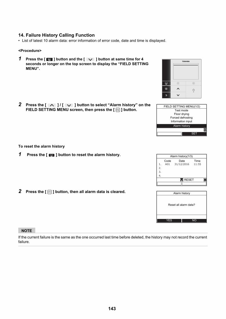
14. Failure History Calling Function• List of latest 10 alarm data: error information of error code, date and time is displayed.
<Procedure>
To reset the alarm history
NOTE
If the current failure is the same as the one occurred last time before deleted, the history may not record the current failure.
1 Press the [ ] button and the [ ] button at same time for 4 seconds or longer on the top screen to display the “FIELD SETTING MENU”.
2 Press the [ ] / [ ] button to select “Alarm history” on the FIELD SETTING MENU screen, then press the [ ] button.
1 Press the [ ] button to reset the alarm history.
2 Press the [ ] button, then all alarm data is cleared.
Test modeFIELD SETTING MENU(1/2)
Floor dryingForced defrostingInformation input
Alarm history
SET
Alarm history(1/3)
RESET
Code Date Time
Alarm history
NOYES
Reset all alarm data?
143

15. Floor drying• This function is available only for the header remote controller.• This function is used for drying concrete etc.• Service personnel must operate the unit after setting the related function code.• Operation is not started unless All the related function codes are set.• Refer to the following for the settings of the related items. Please setup on the responsibility for an installer. An
unsuitable setup may cause a crack of concrete etc.• When the operation starts, the unit operates as follows.
1 Press the [ ] button and the [ ] button at same time for 4 seconds or longer on the top screen to display the “FIELD SETTING MENU”.
2 Press the [ ] / [ ] button to select "Floor drying" on the FIELD SETTING MENU, then press the [ ] button for 4 seconds or longer.
FC:14 setting start and End temperature [20-55°C]FC:15 setting Max temperature [20-55°C]FC:16 continuation days for every step up to Max temperature [1-7 days]FC:17 temperature difference for every step up to Max temperature [1-10 K]FC:18 continuation days for every step down to End temperature [1-7 days]FC:19 temperature difference for every step down to End temperature [1-10 K]FC:1A Continuation days in Max temperature [1-30 days]
3 Press the [ ] / [ ] button to select FC number or Data, then press the [ ] / [ ] button to set the value.
4 Press the [ ] button. The set value is registered.
Test modeFIELD SETTING MENU(1/2)
Floor drying
Forced defrostingInformation input
Alarm history
SET
FC:14
FC:15
FC:16
°C504948474645444342414039383736353433323130292827262524::10 0 1 2 3 4 5 6 7 8 9 10 11 12 13 14 15 16 17 18 19 20 21 22 Day
FC:17
FC:1A
FC:19FC:18
lapsed days
setting temperature
total days
Floor drying
FC No. Data
FIX
144

To start the operation
1 Press the [ ] button and the [ ] button at same time for 4 seconds or longer on the top screen to display the “FIELD SETTING MENU”.
2 Press the [ ] / [ ] button to select “Floor drying” on the FIELD SETTING MENU, then press the [ ] button.
3 Press the [ ] button to select the ON, then press the [ ] button.• Check the total days for Floor drying operation, then press [ ] button.
The mark and mark appears on the Top screen.
4 Start the heating operation on the top screen.• Then ZONE1 mark blinks during Floor drying operation and lapsed days
are displayed.
• If some abnormalities occur during Floor drying operation, the System stops and Alarm history screen is displayed.
• After heating operation is stopped by operating the remote controller during Floor drying operation, if heating operation is again started within 30 minutes, Floor drying operation is started from the time of stopping.
Test modeFIELD SETTING MENU(1/2)
Floor drying
Forced defrostingInformation input
Alarm history
SET
Floor drying
ONOFF
FIX
ZONE1 HOT WATER
HEAT/COOL HOT WATER
MON
145

Outdoor unit
16. Outdoor Unit Setting16-1. Refrigerant recovery controlAlthough HFC refrigerant is "Ozone depletion potential = 0", emission control is applied to it as a greenhouse effect gas.This model has a switch for the outdoor unit to perform an environment-friendly refrigerant recovery operation (pump down) when the model is replaced or discarded.
[How to operate]
1 Remove the water in the hydro unit.(With the water remained in the hydro unit, performing refrigerant recovery may freeze the water and burst the unit.) *1
2 Set all the SW804 dip switches to OFF (initial status), and press the push-button switch SW801 for approx. 1 second.A cooling operation starts. (During the operation, D805 (green LED) blinks.Note that this operation lasts for 10 minutes.
3 After 3 minutes has passed, close the liquid-side valve.
4 After the refrigerant recovery is completed, close the gas-side valve.
5 Press again the push-button switch SW801 for approx. 1 second. The outdoor unit stops operation (cooling).
*1 : If can not remove the water
Operate the circulation pump, to prevent freezing.
1.Turn off the power. (hydro and outdoor unit)2.Set SW06-2 “ON”.3.Turn on the power. (hydro and outdoor unit)4.Rotate switch SW01 to position “1” and press tactile switch SW07 for 5 sec, or longer.5.Rotating the rotary SW01 to position “16”.6.If you finish refrigerant recovery operation, set SW06-2 “OFF” and set SW01 “1”.
12
34
ON
12
34
ON
12
34
ON
D800D801 D802 D803D804 D805
SW804 All OFF (Initial status)
SW801 Press for approx. 1 sec
SW805 (Green LED) blinks.
<HWS-P805HR-E, P1105HR-E>
146
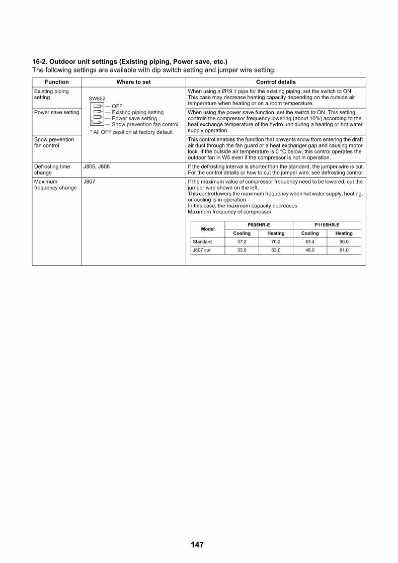
16-2. Outdoor unit settings (Existing piping, Power save, etc.)The following settings are available with dip switch setting and jumper wire setting.
Function Where to set Control details
Existing piping setting
When using a Ø19.1 pipe for the existing piping, set the switch to ON.This case may decrease heating capacity depending on the outside air temperature when heating or on a room temperature.
Power save setting When using the power save function, set the switch to ON. This setting controls the compressor frequency lowering (about 10%) according to the heat exchange temperature of the hydro unit during a heating or hot water supply operation.
Snow prevention fan control
This control enables the function that prevents snow from entering the draft air duct through the fan guard or a heat exchanger gap and causing motor lock. If the outside air temperature is 0 °C below, this control operates the outdoor fan in W5 even if the compressor is not in operation.
Defrosting time change
J805, J806 If the defrosting interval is shorter than the standard, the jumper wire is cut.For the control details or how to cut the jumper wire, see defrosting control.
Maximum frequency change
J807 If the maximum value of compressor frequency need to be lowered, cut the jumper wire shown on the left.This control lowers the maximum frequency when hot water supply, heating, or cooling is in operation.In this case, the maximum capacity decreases.Maximum frequency of compressor
12
34
ON
SW802--- OFF--- Existing piping setting--- Power save setting--- Snow prevention fan control
* All OFF position at factory default
ModelP805HR-E P1105HR-E
Cooling Heating Cooling Heating
Standard 37.2 70.2 53.4 90.0
J807 cut 33.0 63.0 48.0 81.0
147
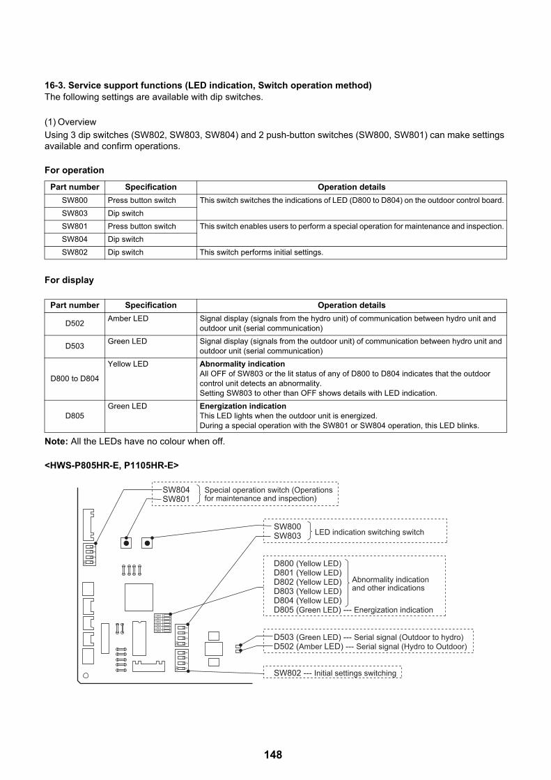
16-3. Service support functions (LED indication, Switch operation method)The following settings are available with dip switches.
(1) Overview
Using 3 dip switches (SW802, SW803, SW804) and 2 push-button switches (SW800, SW801) can make settings available and confirm operations.
For operation
For display
Note: All the LEDs have no colour when off.
<HWS-P805HR-E, P1105HR-E>
Part number Specification Operation details
SW800 Press button switch This switch switches the indications of LED (D800 to D804) on the outdoor control board.
SW803 Dip switch
SW801 Press button switch This switch enables users to perform a special operation for maintenance and inspection.
SW804 Dip switch
SW802 Dip switch This switch performs initial settings.
Part number Specification Operation details
D502Amber LED Signal display (signals from the hydro unit) of communication between hydro unit and
outdoor unit (serial communication)
D503Green LED Signal display (signals from the outdoor unit) of communication between hydro unit and
outdoor unit (serial communication)
D800 to D804
Yellow LED Abnormality indicationAll OFF of SW803 or the lit status of any of D800 to D804 indicates that the outdoor control unit detects an abnormality.Setting SW803 to other than OFF shows details with LED indication.
D805Green LED Energization indication
This LED lights when the outdoor unit is energized.During a special operation with the SW801 or SW804 operation, this LED blinks.
12
34
ON
12
34
ON
12
34
ON
D800D801 D802 D803D804 D805
SW804SW801
SW800SW803 LED indication switching switch
D503 (Green LED) --- Serial signal (Outdoor to hydro)D502 (Amber LED) --- Serial signal (Hydro to Outdoor)
SW802 --- Initial settings switching
D800 (Yellow LED)D801 (Yellow LED)D802 (Yellow LED)D803 (Yellow LED)D804 (Yellow LED)D805 (Green LED) --- Energization indication
Special operation switch (Operations for maintenance and inspection)
Abnormality indication and other indications
148

(2) LED indication switching (SW800, SW803 operation)
(2) -1. Indication switching listOperating SW803 can switch the indications of LED D800 to D804 on the outdoor control board.
Switch Function and details
Abnormality indication (Current abnormality)This switch indicates the current abnormality.Without an abnormality, the lights are off.
(See (2)-2)
Abnormal indication (Latest abnormality: Latest abnormality including the current one)After the abnormality status is released, this setting enables users to see the previous abnormalities.(Previous abnormality can be checked even if the power is once turned off.)* If there is an abnormality now, the abnormality details of the current one is displayed.* This setting does not display a TO sensor failure.
(Check for the failure with the setting for current abnormality.)(See (2)-2)
Temperature sensor indicationThese switches indicate the temperature sensor detecting value.* TC=TWO+2 (heating, hot water supply)
TC=TWO (cooling)(See (2)-3)
Current indicationThis switch indicates the current value in the outdoor unit.
(See (2)-3)
Compressor operation frequency indicationThis switch indicates the compressor operation frequency.
(See (2)-3)
PMV position indicationThis switch indicates PMV (Pulse motor valve) position.
(See (2)-3)
12
34
ON
SW803
12
34
ON
SW803
12
34
ON
TDSW803
12
34
ON
TESW803
12
34
ON
TSSW803
12
34
ON
TOSW803
12
34
ON
TLSW803
12
34
ON
THSW803
12
34
ON
TWISW803
12
34
ON
TC*SW803
12
34
ON
SW803
12
34
ON
SW803
12
34
ON
SW803
149

(2) -2. Abnormality indicationThe current abnormality and the latest abnormality (including the current one) can be identified by the LED D800 to D804 on the outdoor control board.1) Setting all the SW803 dip switches to OFF indicates the current abnormality status.2) Setting SW803 dip switch <1> only to ON indicates the previous abnormality (including the current
one).3) An abnormality lights any of the LEDs from D800 to D804.(Indication 1)4) Pressing the push-button switch SW800 for approx. 1 second switches indication.(Indication 2)5) When SW800 is again pressed or 2 minutes has passed, the indication 1 status returns.
NormalDischarge temperature sensor (TD) failureHeat exchanger temperature sensor (TE) failureHeat exchanger temperature sensor (TL) failureOutside air temperature sensor (TO) failureSuction temperature sensor (TS) failureHeat sink temperature sensor (TH) failureHeat exchanger, suction sensor (TE, TS) wrong wiringHigh pressure sensor (PD) failureEEPROM failureCompressor break downCompressor lockCurrent detection circuit failureFaulty compressor case thermostatNot set up the capacityCombination failure between the hydro unitCommunication failure between MCUsOther abnormality (e.g. Compressor's loss of synchronism)Abnormal discharge temperaturePower failureHeat sink overheat failureGas leakage detection4-way valve reverse failureHi pressure protection operationFan drive system failureCompressor drive Compressor rotor position failure
---F04F06F07F08F12F13F15F24F31H01H02H03H04L10L15L29No abnormality confirmationP03P05P07P15P19P20P22P26P29
12
34
ON
Current abnormalitySW803
12
34
ON
Latest abnormalitySW803
Legend)
---- Off ---- Light ---- BlinkD8
00 (Y
ello
w)D8
01 (Y
ello
w)D8
02 (Y
ello
w)D8
03 (Y
ello
w)D8
04 (Y
ello
w)D8
05 (G
reen
)Indication 1
(Initial indication)Indication 2
(SW800 operation) Abnormality detailsRemote controller Abnormality code
150

(2)-3. Sensor, Current, Compressor operation frequency, PMV position indicationThe values detected by controller, such as temperature sensor or current values, can be easily checked.
* TD, TL, and TH show errors below the ordinary temperature because they are sensors for high temperature.* Current value for the outdoor unit only is shown.
Item setting
LED indication
Temperature sensor ( ) PMV position (pulse)
Current(A)
less than -25 -25 - -21 -20 - -16 -15 - -11 -10 - -6 -5 - -1
0 - 45-9
10-1415-1920-2425-2930-3435-3940-4445-4950-5455-5960-6465-6970-7475-7980-8485-8990-9495-99
100-104105-109110-114115-119
120 or highersensor failure, not connected
0-0.91-1.92-2.93-3.94-4.95-5.96-6.97-7.98-8.99-9.9
10-10.911-11.912-12.913-13.914-14.915-15.916-16.917-17.918-18.919-19.920-20.921-21.922-22.923-23.924-24.925-25.926-26.927-27.928-28.929-29.930-30.9
31 or higher
0-45-9
10-1415-1920-2425-2930-3435-3940-4445-4950-5455-5960-6465-6970-7475-7980-8485-8990-9495-99
100-104105-109110-114115-119120-124125-129130-134135-139140-144145-149150-154
155 or higher
0-1920-3940-5960-7980-99
100-119120-139140-159160-179180-199200-219220-239240-259260-279280-299300-319320-339340-359360-379380-399400-419420-439440-459460-479480-499
500------
Compressor operation frequency
(r.p.s.)
12
34
ON
SW803
12
34
ON
SW803
12
34
ON
SW803
12
34
ON
TDSW803
12
34
ON
TESW803
12
34
ON
TSSW803
12
34
ON
TOSW803
12
34
ON
THSW803
12
34
ON
TASW803
12
34
ON
TC*SW803
12
34
ON
TLSW803
Legend)
---- Off ---- Light
D800
(Yel
low)
D801
(Yel
low)
D802
(Yel
low)
D803
(Yel
low)
D804
(Yel
low)
D805
(Gre
en)
*Refer to page 149
151

(3) Special operation for maintenance and inspection (SW801, SW804)
SW801 and SW804 can perform the following special operations for maintenance and inspection.
1) Switches the dip switch SW804. (See the table below)
2) Presses the push-button switch SW801 for approx. 1 second.
3) Starts the functions shown below. During the start processing of each function, LED D805 (Green) blinks.
4) When the push-button switch SW801 is pressed for approx. 1 second, or the dip switch SW804 is switched, or the defined time for each function has passed, the each function stops and LED D805 (Green) returns to continuous lit.
<Special operation>
SW804 Operation when press button switch SW801 is pressed
Refrigerant recovery operationThe outdoor unit operates cooling. The hydro unit may freeze with this operation alone. Remove beforehand the water in the hydro unit. (See 10-15-1 (See page 146))
Hydro unit cooling requestPerforms a trial cooling operation. (See Note1 (See page 152))
Hydro unit heating requestPerforms a trial heating operation.(See Note1 (See page 152))
Fan motor forcible operationForcibly performs a fan motor operation.When SW801 is pressed again or after 2 minutes, the operation returns to the normal control.
Caution:Although these controls are available during an operation, basically perform them when no operation is in progress.Performing these controls during an operation may cause dangerously rapid pressure change.
(No operation particularly)
PMV full open operationFully opens PMV (Pulse motor valve).When SW801 is pressed again or after 2 minutes, the operation returns to the normal control.
PMV full close operationFully closes PMV (Pulse motor valve).When SW801 is pressed again or after 2 minutes, the operation returns to the normal control.
PMV half open operationHalf opens (250 pulses) PMV (Pulse motor valve).When SW801 is pressed again or after 2 minutes, the operation returns to the normal control.
4-way valve relay operation (RY700, CN700 for check) Sets 4-way valve energization relay (RY700) to ON.When SW801 is pressed again or after 2 minutes, the operation returns to the normal control.
Caution:Do not connect the coil into the body when perform this operation.
(Note 1) The forced test run with this setting cannot be cancelled by the remote controller in the hydro unit.Be sure to cancel the operation from the outdoor unit. (Press again SW801 for 1 second)
12
34
ON
SW804
12
34
ON
SW804
12
34
ON
SW804
12
34
ON
SW804
12
34
ON
SW804
12
34
ON
SW804
12
34
ON
SW804
12
34
ON
SW804
12
34
ON
SW804
152

Self-holding valve vacuum operation (Switch to heating cycle)(RY700, RY701, RY705, CN701 for check)Sets relay RY700, RY701, and RY705 to ON.(CN701 Between 1 to 4 Voltage = Approx. 325V)This function operates for 10 seconds. After that it becomes OFF.
Caution:Although these controls are available during an operation, basically perform them when no operation is in progress.Performing these controls during an operation may cause dangerously rapid pressure change.
Self-holding valve release operation (Switch to cooling cycle)Sets relay RY700 to ON.(CN701 Between 1 to 4 Voltage = Approx. 325V)This function operates for 10 seconds. After that it becomes OFF.
SV (2-way) valve relay operation (RY702, CN702 for check) Sets SV valve relay (RY702) to ON.When SW801 is pressed again or after 2 minutes, the operation returns to the normal control.
Heater output relay operation (RY703, CN703 for check) Sets relay for optional heater (RY703) to ON.When SW801 is pressed again or after 2 minutes, the operation returns to the normal control.
External output relay operation (RY704, CN704 for check) Sets relay for external output (RY704) to ON.When SW801 is pressed again or after 2 minutes, the operation returns to the normal control.
(No operation particularly)
External output relay operation change
Note:Do not use this setting.
SW804 Operation when press button switch SW801 is pressed
(Note 1) The forced test run with this setting cannot be cancelled by the remote controller in the hydro unit.Be sure to cancel the operation from the outdoor unit. (Press again SW801 for 1 second)
12
34
ON
SW804
12
34
ON
SW804
12
34
ON
SW804
12
34
ON
SW804
12
34
ON
SW804
12
34
ON
SW804
12
34
ON
SW804
153

11Replacement of the service PC board
Setting the jumper wires and DIP switches
Model switching (J800 to J803)Since this service PC board is available for several models, cut the jumper wires according to the following table. If they are not cut correctly, an error code “L10” or “L29” appears on the remote controller and the operation of the air conditioner is disabled.
Outdoor unit Service Parts (CDB)
HWS-P805HR-E, P1105HR-E 3026V053 (MCC-1571)
Parts name Function Setting
Jumper wire J800~J803 Model switching Cut these jumper wires according to the following table.
J804~J811 Settings Set these jumper wires to the settings of the PC board before replacement.
DIP switch SW802 Settings Set SW802 to the setting of the PC board before replacement.
SW803 LED indication switching Set SW803 to all OFF.
SW804 Special operations for service
Set SW804 to all OFF.
SW805 (Only H8series) Special operations for service
Set SW805 to all OFF
Model name J 800 J 801 J 802 J 803
Factory default
HWS-805H-E
HWS-1105H-E
HWS-1405H-E
HWS-P805HR-E
HWS-P1105HR-E
* : Characters that indicate the following:No character -- Standard modelsR ----- For with cord heater
:Connected, :Cut
<HWS-P805HR-E, P1105HR-E>
SW802
SW804
J800-J803
SW803
MCC-1571
154

12How to exchange main parts
1. Hydro Unit
WARNING
<Turn off the power breaker>Because the electrical components are energized with high voltage, always turn off the power breaker before starting to work.
<Check>Ensure that no water pressure is present when replacing the water circuit (circulation pump, heater unit, flow switch, etc).After a repair is complete, perform a test run (after attaching the front panel, upper and lower cabinets, and side cabinet) and check that no abnormality including smoke or abnormal noise occurs. Failure to do so may cause a fire or an electric shock. Place the cabinets before making a test run.
<Watch out for fire>Observe the following instructions when repairing the refrigerant cycle.(1) Watch out for surrounding fire. Always put out the fire of stove burner or other devices before starting the repair.
Should the fire fail to be put out, the oil mixed with refrigerant gas could catch fire.(2) Do not use a welder in a closed room.
A room with no ventilation may cause carbon monoxide poisoning.(3) Keep away flammable materials.
The materials may catch the fire of a welder.
CAUTION
<Wear gloves>Wear gloves (∗) when performing repair.Failure to do so may cause an injury when accidentally contacting the parts.∗: Thick gloves such as cotton work gloves
No. Exchange parts name Work procedure Remarks
1 Common procedure
Front panel
Electrical control box cover (lower)
Electrical control box cover (upper)
1. How to remove1)Stop the hydro unit operation, and turn off the power
breaker.2)Remove the front panel.
(ST1T Ø4 × 10, 6 screws)3)After unscrew the screws, remove the front panel by
pulling it toward you.4)Remove the electrical control box cover (lower).
(ST2T Ø4 × 8, 2 screws)5)Disconnect the power source cable and outdoor unit
connecting cable from the terminal block.6)Remove the electrical control box cover (upper).
(ST2T Ø4 × 8, 4 screws)7)Disconnect the remote controller connecting cable
from the CN41 connector of the water heat exchange board.
2. How to attach1)Connect the remote controller connecting cable to
the water heat exchange board.2)Attach the electrical control box cover (upper).3)Connect the power source cable and outdoor unit
connecting cable to the terminal block, and fix with the cord clamp.
4)Attach the electrical control box cover (lower).5)Attach the front panel.
Wear gloves when performing the work.Failure to do so may cause an injury when accidentally contacting the parts.
Front panel
Electrical control box cover (lower)
Electrical control box cover (upper)
155
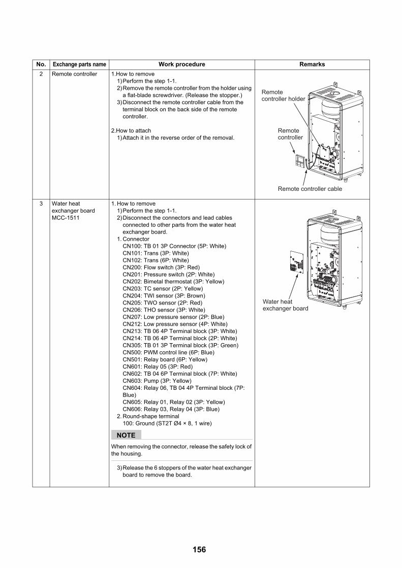
2 Remote controller 1.How to remove1)Perform the step 1-1. 2)Remove the remote controller from the holder using
a flat-blade screwdriver. (Release the stopper.)3)Disconnect the remote controller cable from the
terminal block on the back side of the remote controller.
2.How to attach1)Attach it in the reverse order of the removal.
3 Water heat exchanger boardMCC-1511
1. How to remove1)Perform the step 1-1. 2)Disconnect the connectors and lead cables
connected to other parts from the water heat exchanger board.
1. ConnectorCN100: TB 01 3P Connector (5P: White)CN101: Trans (3P: White)CN102: Trans (6P: White)CN200: Flow switch (3P: Red)CN201: Pressure switch (2P: White)CN202: Bimetal thermostat (3P: Yellow)CN203: TC sensor (2P: Yellow)CN204: TWI sensor (3P: Brown)CN205: TWO sensor (2P: Red)CN206: THO sensor (3P: White)CN207: Low pressure sensor (2P: Blue)CN212: Low pressure sensor (4P: White)CN213: TB 06 4P Terminal block (3P: White)CN214: TB 06 4P Terminal block (2P: White)CN305: TB 01 3P Terminal block (3P: Green)CN500: PWM control line (6P: Blue)CN501: Relay board (6P: Yellow)CN601: Relay 05 (3P: Red)CN602: TB 04 6P Terminal block (7P: White)CN603: Pump (3P: Yellow)CN604: Relay 06, TB 04 4P Terminal block (7P: Blue)CN605: Relay 01, Relay 02 (3P: Yellow)CN606: Relay 03, Relay 04 (3P: Blue)
2. Round-shape terminal100: Ground (ST2T Ø4 × 8, 1 wire)
NOTE
When removing the connector, release the safety lock of the housing.
3)Release the 6 stoppers of the water heat exchanger board to remove the board.
No. Exchange parts name Work procedure Remarks
Remote Remote controllercontroller
Remote controller cableRemote controller cable
Remote controller holder
Remote controller
Remote controller cable
Water heat Water heat exchanger boardexchanger boardWater heat exchanger board
156

4 Relay boardMCC-1431
1. How to remove1)Perform the step 1-1. 2)Disconnect the connectors and lead cables
connected to other parts from the relay board.
1. ConnectorCN01: TB 01 3P Terminal block (3P: White)CN02: Water heat exchanger board (5P: White)CN10: TB 05 9P Terminal block (9P: White)
NOTE
When removing the connector, release the safety lock of the housing.
3)Release the 3 stoppers of the relay board to remove the board.
5 Electric parts assembly
1. How to remove1)Perform the step 1-1. 2)Disconnect the connectors and lead cables
connected to other parts from the water heat exchanger board.
1. ConnectorCN200: Flow switch (3P: Red)CN201: Pressure switch (2P: White)CN202: Bimetal thermostat (3P: Yellow)CN203: TC sensor (2P: Yellow)CN204: TWI sensor (3P: Brown)CN205: TWO sensor (2P: Red)CN206 THO sensor (3P: White)CN207: Low pressure sensor (2P: Blue)CN212: Low pressure sensor (4P: White)CN603: Pump (3P: Yellow)Disconnect the heater power source cable (For backup heater and hot water cylinder heater) from the MgSW.
NOTE
When removing the connector, release the safety lock of the housing.
3)Remove the fixed screws.(ST2T Ø4 × 8, 2 screws)
4)Remove the electric parts assembly by pulling it toward you while pulling it upward because the assembly back side has a hook holding structure.
No. Exchange parts name Work procedure Remarks
Relay boardRelay boardRelay board
Electric parts assemblyElectric parts assemblyElectric parts assembly
157

6 Side board 1. Side board (Right) 1)Perform the step 1-1-1), 2), 3). 2)Remove the fixed screws of the side board (Right).
(ST1T Ø4 × 10, 5 screws)3)Remove the fixed screws of the side board (Right)
and the manometer fixing board. (ST1T Ø4 × 10, 2 screws)
2. Side board (Left) 1)Remove the fixed screws of the side board (Left).
(ST1T Ø4 × 10, 5 screws)
7 Upper board 1)Perform the step 1-1-1), 2), 3) and step 6.2)Remove the fixed screws of the upper board.
(ST1T Ø4 × 10, 4 screws)
8 Bottom board 1)Perform the step 1-1-1), 2), 3) and step 6.2)Remove the fixed screws of the bottom board.
(ST1T Ø4 × 10, 4 screws)Removal is required if water and refrigerant piping are connected.
No. Exchange parts name Work procedure Remarks
Side board (Right)
Side board (Left)
UpperUpperUpper board
Bottom boardBottom boardBottom board
158
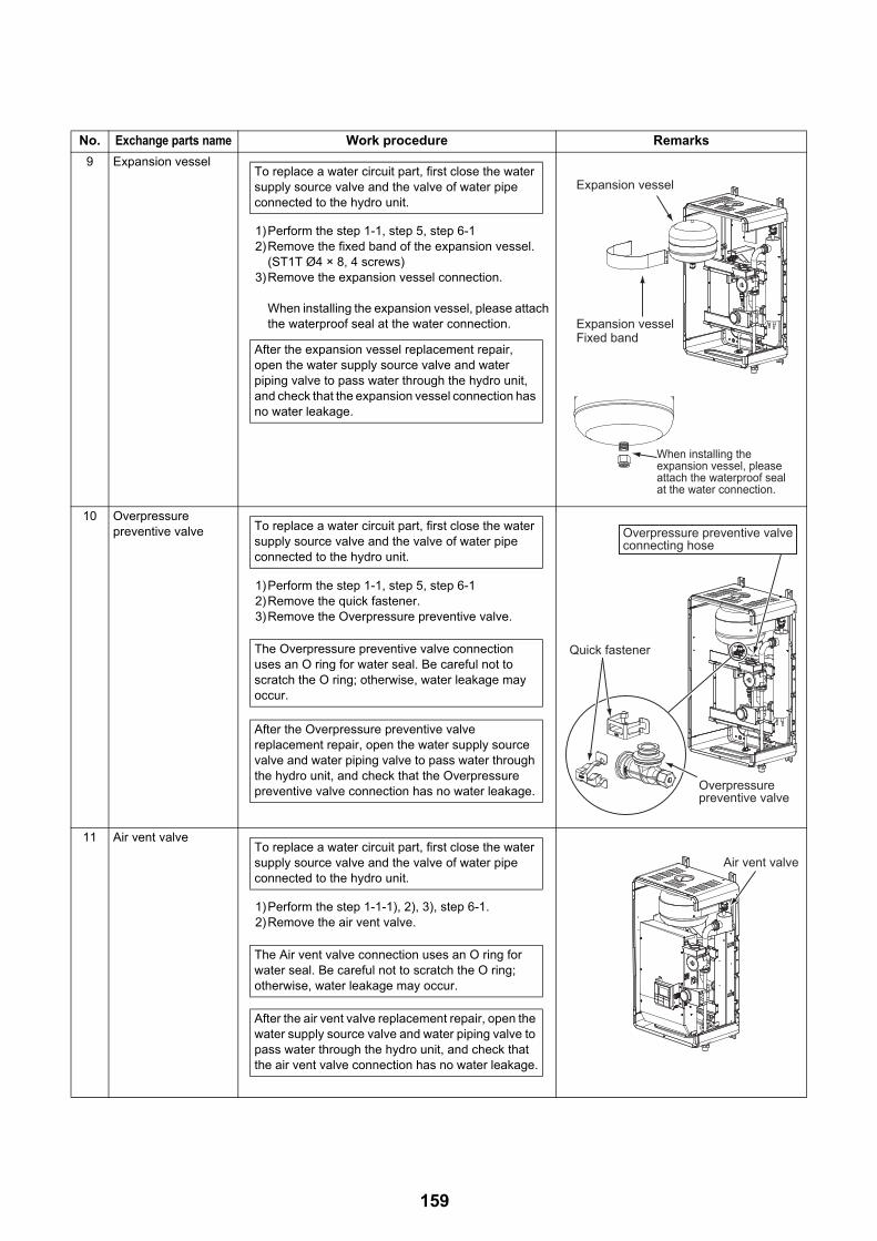
9 Expansion vessel
1)Perform the step 1-1, step 5, step 6-12)Remove the fixed band of the expansion vessel.
(ST1T Ø4 × 8, 4 screws)3)Remove the expansion vessel connection.
When installing the expansion vessel, please attach the waterproof seal at the water connection.
10 Overpressure preventive valve
1)Perform the step 1-1, step 5, step 6-12)Remove the quick fastener.3)Remove the Overpressure preventive valve.
11 Air vent valve
1)Perform the step 1-1-1), 2), 3), step 6-1.2)Remove the air vent valve.
No. Exchange parts name Work procedure Remarks
To replace a water circuit part, first close the water supply source valve and the valve of water pipe connected to the hydro unit.
After the expansion vessel replacement repair, open the water supply source valve and water piping valve to pass water through the hydro unit, and check that the expansion vessel connection has no water leakage.
Expansion vesselExpansion vessel
Expansion vesselExpansion vesselFixed bandFixed band
Expansion vessel
Expansion vesselFixed band
When installing the expansion vessel, please attach the waterproof seal at the water connection.
To replace a water circuit part, first close the water supply source valve and the valve of water pipe connected to the hydro unit.
The Overpressure preventive valve connection uses an O ring for water seal. Be careful not to scratch the O ring; otherwise, water leakage may occur.
After the Overpressure preventive valve replacement repair, open the water supply source valve and water piping valve to pass water through the hydro unit, and check that the Overpressure preventive valve connection has no water leakage.
Quick fastener
Overpressure preventive valve
Overpressure preventive valve connecting hose
To replace a water circuit part, first close the water supply source valve and the valve of water pipe connected to the hydro unit.
The Air vent valve connection uses an O ring for water seal. Be careful not to scratch the O ring; otherwise, water leakage may occur.
After the air vent valve replacement repair, open the water supply source valve and water piping valve to pass water through the hydro unit, and check that the air vent valve connection has no water leakage.
Air vent valveAir vent valveAir vent valve
159
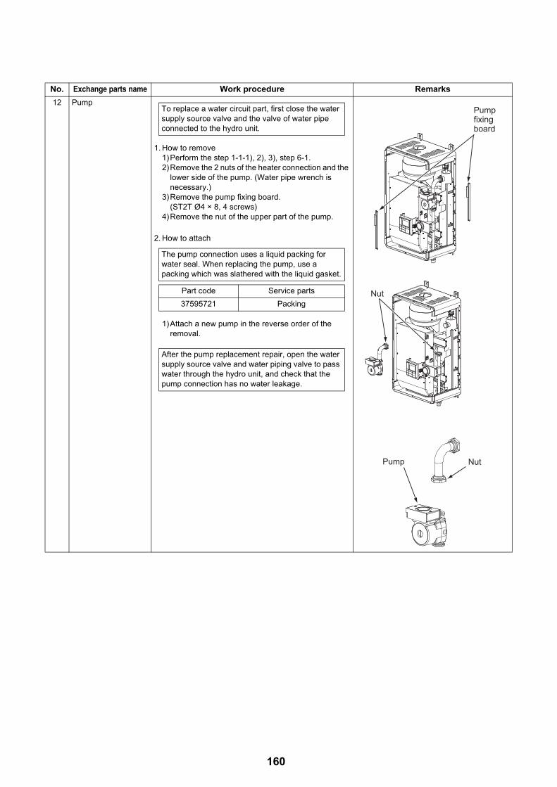
12 Pump
1. How to remove1)Perform the step 1-1-1), 2), 3), step 6-1.2)Remove the 2 nuts of the heater connection and the
lower side of the pump. (Water pipe wrench is necessary.)
3)Remove the pump fixing board.(ST2T Ø4 × 8, 4 screws)
4)Remove the nut of the upper part of the pump.
2. How to attach
1)Attach a new pump in the reverse order of the removal.
No. Exchange parts name Work procedure Remarks
To replace a water circuit part, first close the water supply source valve and the valve of water pipe connected to the hydro unit.
The pump connection uses a liquid packing for water seal. When replacing the pump, use a packing which was slathered with the liquid gasket.
Part code Service parts
37595721 Packing
After the pump replacement repair, open the water supply source valve and water piping valve to pass water through the hydro unit, and check that the pump connection has no water leakage.
Pump Pump fixing fixing boardboard
NutNut
NutNutPump Pump
Pump fixing board
Nut
NutPump
160

13 Flow switch
1. How to remove1)Perform the step 1-1 and step 5. 2)Remove the flow switch.
2. How to attach1)Attach a new flow switch in the reverse order of the
removal.
NOTE
As shown on the right,place a flow sensor parallel to the water heat exchanger inlet pipe so that the wire is place on the right side from the front view.
14 Manometer
1. How to remove1)Perform the step 1-1 and step 5 and 6. 2)Remove the manometer.
No. Exchange parts name Work procedure Remarks
To replace a water circuit part, first close the water supply source valve and the valve of water pipe connected to the hydro unit.
The flow switch connection uses an O ring for water seal. Be careful not to scratch the O ring; otherwise, water leakage may occur.
After the flow switch replacement repair, open the water supply source valve and water piping valve to pass water through the hydro unit, and check that the flow switch connection has no water leakage.
Flow switchFlow switch
Flow switchFlow switch
Flow switch
Flow switch
Water heat inlet pipe
Wire
To replace a water circuit part, first close the water supply source valve and the valve of water pipe connected to the hydro unit.
After the manometer replacement repair, open the water supply source valve and water piping valve to pass water through the hydro unit, and check that the manometer connection has no water leakage.
ManometerManometerManometer
161

15 Heater assembly
1. How to remove1)Perform the step 1-1, step 5, 6, 7, and 11.2)Remove the nut of the heater connection.3)Remove the 2 fixed screws of the heater.4)Pull the heater out upward.5)Remove the insulator from the heater.
2. How to attach
1)Attach a new heater in the reverse order of the removal.
16 TC sensorTWI sensorTWO sensorTHO sensor
1. How to remove1)Perform the step 1-1 and step 5. 2)Take the sensor out.
No. Exchange parts name Work procedure Remarks
To replace a water circuit part, first close the water supply source valve and the valve of water pipe connected to the hydro unit.
The heater connection uses a liquid packing for water seal. When replacing the heater, use a packing which was slathered with the liquid gasket.
Part code Service parts
37595721 Packing
After the heater assembly replacement repair, open the water supply source valve and water piping valve to pass water through the hydro unit, and check that the heater connection has no water leakage.
NutNut
Heater Heater assemblyassembly
Nut
Heater Heater assemblyassemblyHeater assembly
InsulatorInsulatorInsulator
Heater assembly
THO sensorSensor diameter: 6Tube color: Gray
TWI sensorSensor diameter: 4Tube color: Blue
TWO sensorSensor diameter: 6Tube color: Red
TC sensorSensor diameter: 6Tube color: Black
162

17 Water heat exchanger assembly
1. How to remove1)Perform the step 1-1, step 5, 6, and 8.2)Remove the water pipe fixing board.
(ST2T Ø4 × 8, 2 screws)3)Remove the refrigerant piping fixing board.
(ST2T Ø4 × 8, 3 screws)4)Remove the nut of the heater connection.5)Remove the fixed screws of the electrical control
box fixing board.(ST2T Ø4 × 8, 4 screws)
6)Remove the side reinforcing board (left).(ST2T Ø4 × 8, 6 screws) 3 for inside, 3 for outside
7)Remove the water heat exchanger fixing band.(ST2T Ø4 × 8, 6 screws)
8)Remove the water heat exchanger assembly.
2. How to attach1)Attach a new water heat exchanger assembly in the
reverse order of the removal. 2)Restore all piping and wiring as in the original state,
and check that there is no water or refrigerant leakage.
No. Exchange parts name Work procedure Remarks
• Close the water piping source valve and the valve of water pipe connected to the hydro unit, and then remove the refrigerant and water piping.
• Perform refrigerant recovery with the outdoor unit.
• Disconnect all the power source cable, outdoor unit connection cable, and cylinder connection cable.
The heater connection uses a packing for water seal. Be careful not to scratch the packing; otherwise, water leakage may occur.
• After the water heat exchanger assembly replacement repair, open the water supply source valve and water piping source valve to pass water through the hydro unit, and check that the connection has no water leakage.
• After connecting the refrigerant pipe, check that the connection has no refrigerant leakage.
Water Water piping fixingpiping fixing
Refrigerant Refrigerant piping fixing piping fixing boardboard
NutNut
Water piping fixing
Refrigerant piping fixing board
Nut
Electrical control box fixing
Side Side reinforcing reinforcing board (left)board (left)
Side reinforcing board (left)
Water heat exchanger assembly
Water heat exchanger fixing band
The piping structure slightly differs in 11 kW and 8 kW specifications.
163

2. Outdoor Unit
HWS-P805HR-E, P1105HR-E
No. Exchange parts name Work procedure Remarks
1 Common procedureNOTE
Wear gloves when performing the work.Failure to do so may cause an injury when accidentally contacting the parts.
1. How to remove1)Stop the operation by remote controller and turn
off the breaker.2)Remove the front panel.
(Hex Ø4 × 10, 2 screws)• After unscrewing the screws, remove the front
panel while pulling it downward.3)Disconnect the power source cable and
connecting cables between hydro and outdoor from the cord clamp and terminals.
4)Remove the top board.(Hex Ø4 × 10, 5 screws)
2. How to attach
1)Attach the top board.(Hex Ø4 × 10, 5 screws)
2)Connect the power source cable and connecting cables between hydro and outdoor to the terminal, and fix them with the cord clamp.
NOTE
The power source cable and connecting cable between hydro and outdoor units must be fixed along the connecting piping by using a cable tie so that the cables do not contact the compressor, gas side valve, gas side piping and outlet pipe.
3)Attach the front panel.(Hex Ø4 × 10, 2 screws)
Front panel
Top board
164

2 Outlet cabinet How to remove1) Perform the step 1-1. 2)Remove the screws of the outlet cabinet and
parting board.(ST1T Ø4 × 8, 4 screws)
3)Remove the screws of the outlet cabinet and bottom board.(Hex Ø4 × 10, 2 screws)
4)Remove the screws of the outlet cabinet and motor base.(ST1T Ø4 × 8, 2 screws)
5)Remove the screws of the outlet cabinet and heat exchanger.(ST1T Ø4 × 8, 1 screws)
6)Remove the screws of the outlet cabinet and fin guard.(Hex Ø4 × 10, 2 screws)
3 Side cabinet 1)Perform the step 1-1. 2)Remove the screws that fixes the inverter
assembly and the side cabinet.(ST1T Ø4 × 8, 2 screws)
3)Remove the screws of the side cabinet and valve fixing board.(ST1T Ø4 × 8, 2 screws)
4)Remove the screws of the side cabinet and piping panel (back).(Hex Ø4 × 10, 2 screws)
5)Remove the screws of the side cabinet and bottom board.(Hex Ø4 × 10, 1 screws)
6)Remove the screws of the side cabinet and fin guard (heat exchanger).(Hex Ø4 × 10, 5 screws)
7)Remove the side cabinet while shifting it upward (inverter hook).
No. Exchange parts name Work procedure Remarks
Outlet cabinetHeat exchangerMotor base Paring board
Fin guard
Inverter assembly Side cabinet
Valve fixing board
165

4 Electric parts replacement
1. Control board1)Perform the step 1-1.
WARNING
For 1 minute after the power is turned off, do not disassemble the inverter to prevent an electric shock.
2)Remove the connector connected to the control (Hydro power source, temperature sensor, electric control valve coil, 4-way valve coil, compressor case thermostat, fan motor, high pressure switch)
* Remove the connector by releasing the lock in the housing.
3)Remove the lead cable connected to the control board. Compressor lead U: CN200 Red
V: CN201 WhiteW: CN202 Black
Reactor lead connector Aconnector B
4)Remove the earth wire of the control board.(Truss B tight screw Ø4 × 6, 1 screw)
5)Remove the fixed screws of the control board.(Collar screw for fixing element Ø3 × 16, 9 screws, Pan S-tight screw for fixing the board Ø3 × 20, 1 screw)
6)Remove the control board.(Supporter 5 positions)Note) Removing the control board may be difficult
due to the heat release grease for the heat sink.
7)Attach a new control board.
NOTE
• Be careful for not taking the compressor lead V: CN201 White for the reactor lead CN05 or 06 White.(The compressor lead has a transparent sleeve at its ring terminal. The reactor lead ring terminal does not have sleeve.)
• Be sure to attach the insulating sheet.(Applying beforehand a bit of heat release grease to the back side of the insulating sheet can easily paste the sheet to the heat sink.)
No. Exchange parts name Work procedure Remarks
Control board
Control boardInsulating sheet
Hear release grease
Fan motor (upper)
Fan motor (lower)
Reactor lead connector A
Reactor lead connector B
Compressor lead
4-way valve coil
Temperature sensor
Hydro power sourceMotorized control coil
Screw for fixing board
Screw for fixing element (9 positions)
Earth wire
Compressor case thermostat
High pressure switch
166
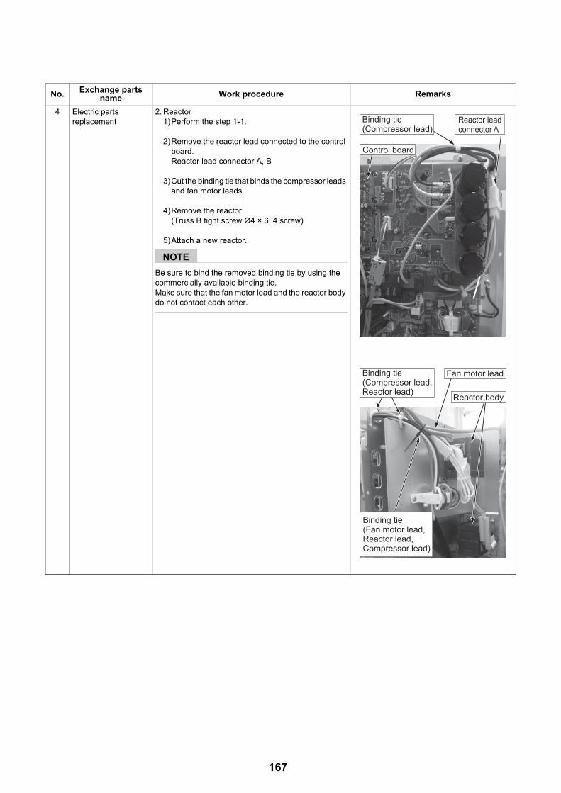
4 Electric parts replacement
2. Reactor1)Perform the step 1-1.
2)Remove the reactor lead connected to the control board.Reactor lead connector A, B
3)Cut the binding tie that binds the compressor leads and fan motor leads.
4)Remove the reactor.(Truss B tight screw Ø4 × 6, 4 screw)
5)Attach a new reactor.
NOTE
Be sure to bind the removed binding tie by using the commercially available binding tie.Make sure that the fan motor lead and the reactor body do not contact each other.
No. Exchange parts name Work procedure Remarks
Reactor body
Fan motor lead
Binding tie(Compressor lead)
Binding tie(Compressor lead,Reactor lead)
Binding tie(Fan motor lead,Reactor lead, Compressor lead)
Control board
Reactor lead connector A
167
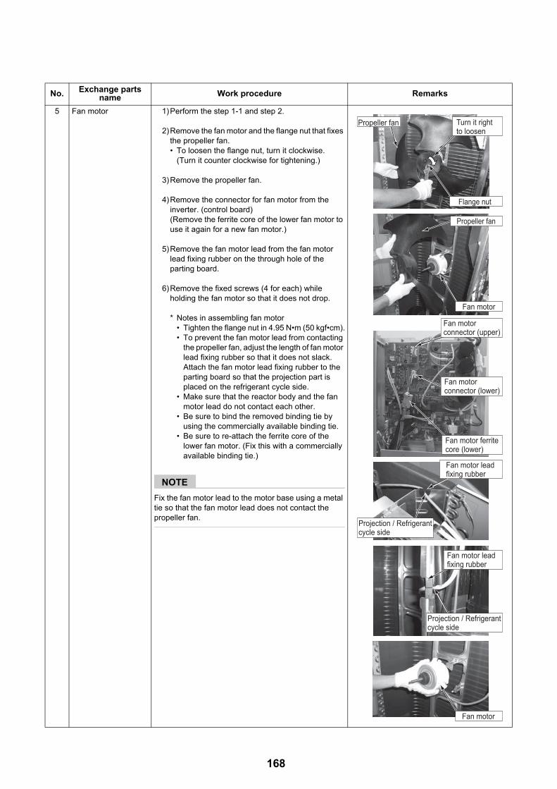
5 Fan motor 1)Perform the step 1-1 and step 2.
2)Remove the fan motor and the flange nut that fixes the propeller fan.• To loosen the flange nut, turn it clockwise.
(Turn it counter clockwise for tightening.)
3)Remove the propeller fan.
4)Remove the connector for fan motor from the inverter. (control board)(Remove the ferrite core of the lower fan motor to use it again for a new fan motor.)
5)Remove the fan motor lead from the fan motor lead fixing rubber on the through hole of the parting board.
6)Remove the fixed screws (4 for each) while holding the fan motor so that it does not drop.
* Notes in assembling fan motor• Tighten the flange nut in 4.95 N•m (50 kgf•cm).• To prevent the fan motor lead from contacting
the propeller fan, adjust the length of fan motor lead fixing rubber so that it does not slack. Attach the fan motor lead fixing rubber to the parting board so that the projection part is placed on the refrigerant cycle side.
• Make sure that the reactor body and the fan motor lead do not contact each other.
• Be sure to bind the removed binding tie by using the commercially available binding tie.
• Be sure to re-attach the ferrite core of the lower fan motor. (Fix this with a commercially available binding tie.)
NOTE
Fix the fan motor lead to the motor base using a metal tie so that the fan motor lead does not contact the propeller fan.
No. Exchange parts name Work procedure Remarks
Propeller fan
Fan motor ferrite core (lower)
Fan motor connector (upper)
Fan motor connector (lower)
Fan motor lead fixing rubber
Fan motor lead fixing rubber
Fan motor
Fan motor
Turn it right to loosen
Flange nut
Propeller fan
Projection / Refrigerant cycle side
Projection / Refrigerant cycle side
168
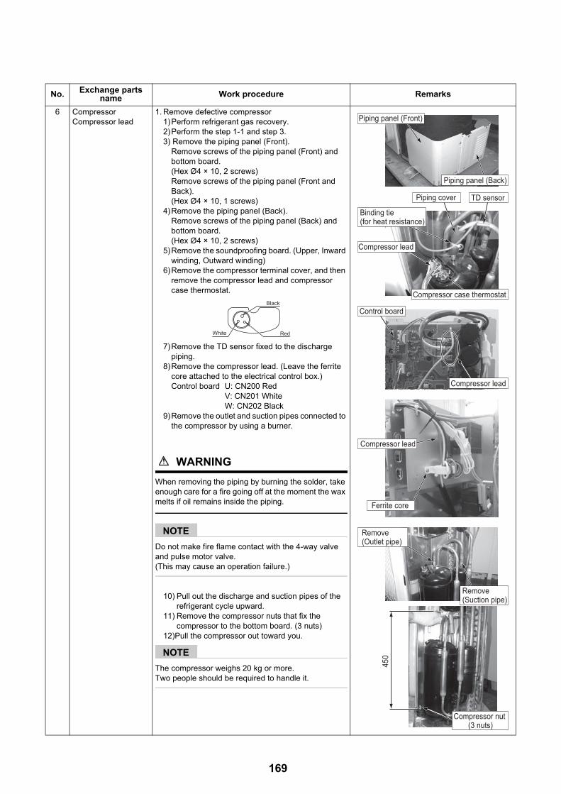
6 CompressorCompressor lead
1. Remove defective compressor1)Perform refrigerant gas recovery.2)Perform the step 1-1 and step 3.3) Remove the piping panel (Front).
Remove screws of the piping panel (Front) and bottom board.(Hex Ø4 × 10, 2 screws)Remove screws of the piping panel (Front and Back).(Hex Ø4 × 10, 1 screws)
4)Remove the piping panel (Back).Remove screws of the piping panel (Back) and bottom board.(Hex Ø4 × 10, 2 screws)
5)Remove the soundproofing board. (Upper, Inward winding, Outward winding)
6)Remove the compressor terminal cover, and then remove the compressor lead and compressor case thermostat.
7)Remove the TD sensor fixed to the discharge piping.
8)Remove the compressor lead. (Leave the ferrite core attached to the electrical control box.)Control board U: CN200 Red
V: CN201 WhiteW: CN202 Black
9)Remove the outlet and suction pipes connected to the compressor by using a burner.
WARNING
When removing the piping by burning the solder, take enough care for a fire going off at the moment the wax melts if oil remains inside the piping.
NOTE
Do not make fire flame contact with the 4-way valve and pulse motor valve.(This may cause an operation failure.)
10) Pull out the discharge and suction pipes of the refrigerant cycle upward.
11) Remove the compressor nuts that fix the compressor to the bottom board. (3 nuts)
12)Pull the compressor out toward you.
NOTE
The compressor weighs 20 kg or more.Two people should be required to handle it.
No. Exchange parts name Work procedure Remarks
White
Black
Red
Piping panel (Front)
Piping panel (Back)
450
TD sensorPiping cover
Binding tie (for heat resistance)
Remove (Outlet pipe)
Compressor nut (3 nuts)
Remove (Suction pipe)
Compressor case thermostat
Compressor lead
Compressor lead
Compressor lead
Ferrite core
Control board
169

6 CompressorCompressor lead
2. Attach the compressor1)Attach the compressor in the reverse order of the
removal.
NOTE
• Be sure to replace the compressor lead after the compressor replacement. (Compressor lead spare parts code: 43160591)At this time, wind the ferrite core with the compressor lead for 4 times.
• Attach the soundproofing board (Inward winding, Outward winding), as shown in the right figure, through between the compressor and between the piping and parting board.
• Fix the TD sensor with a commercially available heat resistant binding tie through the piping cover so that the sensor do not contact the discharge pipe.
3)Vacuuming1)Connect the vacuum pump to the charge port and
check joint of the gas piping valve to operate the vacuum pump.
2)Perform vacuuming until the vacuum low pressure gauge shows 1(mmHg).
NOTE
Open fully the pulse motor valve before vacuuming. With the valve closed, vacuuming between the outdoor unit liquid valve and the pulse motor valve may fail.
How to make pulse motor valve forcible full open• Turn on the electric leakage breaker.• Set the SW804 dip switch 1 and 3 on the outdoor
unit control board to ON.• Press SW801 on the outdoor unit control board
for 1 second or longer.• After pressing SW801 for 1 second or longer,
turn off the electric leakage breaker within 2 minutes.
4. Charge refrigerant1)Add refrigerant whose amount is defined
according to the piping length from the valve charge port. (HWS-P805HR-E, P1105HR-E : 2.7 kg)
No. Exchange parts name Work procedure Remarks
Overlap soundproofing board (Outward winding) at this position
Place soundproofing board (Outward winding) through between suction pipe and header pipe
Overlap soundproofing board (Inward winding) at this position through between compressor, outlet pipe, and suction pipe
Do not make space between soundproofing boards (Upper and Outward winding)
Wind ferrite core with compressor lead for 4 times
0 to 50 (Compressor lead positioning standard)
Compressor lead
Ferrite core
Suction pipe Discharge pipe
Soundproofing board (Upper)
Soundproofing board (Outward winding)
SW801SW804
Make the other end of the line go through under the rivet
Rivet
Header pipe
170

7 Pulse motor valve coil 1. How to remove1)Perform the step 1-1.2)Remove the coil from the pulse motor valve body
by pulling upward while rotating the coil.
2. How to attach1)Fix the coil by exactly adjusting the coil positioning
projection to the recess of the pulse motor valve body.
8 Fan guard 1. How to remove1)Perform the step 1-1 and step 2.
NOTE
Perform a replacement work on cardboard or cloth to prevent the product from being damaged.
2)Remove the outlet cabinet and put with the fan guard side down.
3)Remove the screw for the bell mouth and fan guard.(PT2P Ø3 x 14 and washer, 4 pcs.)
4)Release the hooks (8 positions) of the fan guard.
2. How to attach1)Press the hooks (8 positions) with hands from the
front side to fix them.2)Attach the bell mouth fixed with screws and
washers. (PT2P Ø3 x 14 and washer, 4 pcs.)
NOTE
Check that all the hooks are fixed to the given positions.
No. Exchange parts name Work procedure Remarks
Motorized control valve coil
Recess Pulse motor valve body
Positioning projection
Outlet cabinetBellmouth
Hooks
Fan guard
PT2P Ø3 x 14 and washer
171
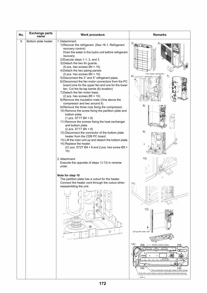
9 Bottom plate heater 1. Detachment1)Recover the refrigerant. (See 16-1. Refrigerant
recovery control)Drain the water in the hydro unit before refrigerant recovery.
2)Execute steps 1-1, 2, and 3. 3)Detach the two fin guards.
(9 pcs. hex screws Ø4 × 10)4)Detach the two piping panels.
(5 pcs. hex screws Ø4 × 10)5)Disconnect the 3” and 5” refrigerant pipes.6)Disconnect the fan motor connectors from the PC
board (one for the upper fan and one for the lower fan. Cut the tie-lap bands (6) location)
7)Detach the fan motor base.(2 pcs. hex screws Ø5 × 10)
8)Remove the insulation mats (One above the compressor and two around it).
9)Remove the three nuts fixing the compressor.10) Remove the screw fixing the partition plate and
bottom plate.(1 pcs. ST1T Ø4 × 8)
11) Remove the screws fixing the heat exchanger and bottom plate. (2 pcs. ST1T Ø4 × 8)
12) Disconnect the connector of the bottom plate heater from the CDB PC board.
13) Lift the main unit up and detach the bottom plate.14) Replace the heater.
(21 pcs. ST2T Ø4 × 8 and 2 pcs. hex screw Ø5 × 10)
2. AttachmentExecute the opposite of steps 1)-13) in reverse order.
Note for step 10The partition plate has a cutout for the heater. Connect the heater cord through the cutout when reassembling the unit.
No. Exchange parts name Work procedure Remarks
Cut out
3) 4)
8)
11)
14)
10)
13)
9)
6) 7)
Only this cord clamp must be attached downward-facing.The connector must get close to this screw.
Lift up the main unit
Bottom plate heater.
Fan motor connection
172
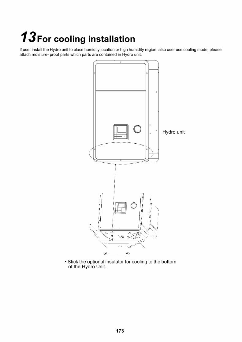
13For cooling installationIf user install the Hydro unit to place humidity location or high humidity region, also user use cooling mode, please attach moisture- proof parts which parts are contained in Hydro unit.
Insulator
Hydro unit
• Stick the optional insulator for cooling to the bottom of the Hydro Unit.
173

14Periodic inspection itemsFor a long-term safe operation of this equipment, perform periodic inspection and parts replacement.
<Inspection items>
Hydro unit (HWS-P805**-E, P1105**-E) Frequency Periodic inspection details
1. Insulation measurement (Power source circuit / Heater circuit)
Annually Insulation measurement with a mega tester
2. Power source measurement (No-load voltage) Annually Electronic voltage measurement: 220-230 V ±10%
3. Operation check Annually Hot water supply / Heating / *-Cooling operation check with remote controller
4. Refrigerant leakage / Water leakage inspection Annually Visual inspection and check with a leak tester: No leakage must be found
5. Water heat exchanger inspection (Internal dirt and clogging)
Annually Checking for water dirtiness in a closed cycle, Cleaning
6. Inlet / Outlet water temperature measurement Annually Temperature measurement: Temperature measurement during an operation
7. Circulation pump inspection Annually No leakage or abnormal noise must be found (Replacement every 10 years: Charged)
8. Air vent valve inspection Annually Water leakage, Air vent
9. Expansion vessel Annually Visual check for charge pressure abnormality, water leakage, or corrosion
10. Heater assembly Annually Check for appearance damage, deformation, or loose terminal
11. Flow switch Annually Operation check while running
12. Manometer Annually Water leakage, water pressure check
13. Safety valve Annually Water leakage, Appearance check, Drainage check
14. Water heat exchanger control board, Terminal block Annually Check for loose connector and connecting terminal
Outdoor unit (HWS-P805HR-E, P1105HR-E) Frequency Periodic inspection details
1. Insulation measurement (Power source circuit / Compressor)
Annually Insulation measurement with a mega tester
2. Power source measurement (No-load voltage / Rated operation)
Annually Electronic voltage measurement: 220-230 V ±10% (Single phase type)
3. Operation frequency (Outdoor unit operation check) Annually Frequency check by rated operation (See 10-13)
4. Refrigerant leakage inspection Annually Visual inspection and check connection with a leak tester: No leakage must be found
5. Air heat exchanger inspection (Dirt and clogging) Annually Visual inspection, Clear clogging
6. Fan inspection (Scratch, damage) Annually Check for scratches or damages to the fan or abnormal motor sound
7. Cycle parts(Compressor, 4-way valve, Pulse motor valve)
AnnuallyAnnually
Operation check by trial run
8. Inverter control board, Terminal block Annually Check for loose connector and connecting terminal
Hot water cylinder(HWS-150CSHM3-E(-UK),
210CSHM3-E(-UK), 300CSHM3-E(-UK))Frequency Periodic inspection details
1. Insulation measurement (Power source circuit) Annually Insulation measurement with a mega tester
2. Power source measurement (No-load voltage) Annually Electronic voltage measurement: 220-230 V ±10%
3. Water leakage inspection Annually Visual inspection for leakage: No leakage must be found
4. Terminal block Annually Check for loose connector and connecting terminal
5. Heater assembly Annually Check for appearance damage, deformation, or loose terminal
6. Temperature, Pressure relief valve (Specification for UK only)
Annually Drainage check
174

15Part exploded view, part listHydro Unit
241
242
209
218
244
243
213
242
211
202
203
201
206
215
216
217
207
204
236
205
237
210
203
212
208
238
Por
tion
A
Det
ails
of p
ortio
n A
175
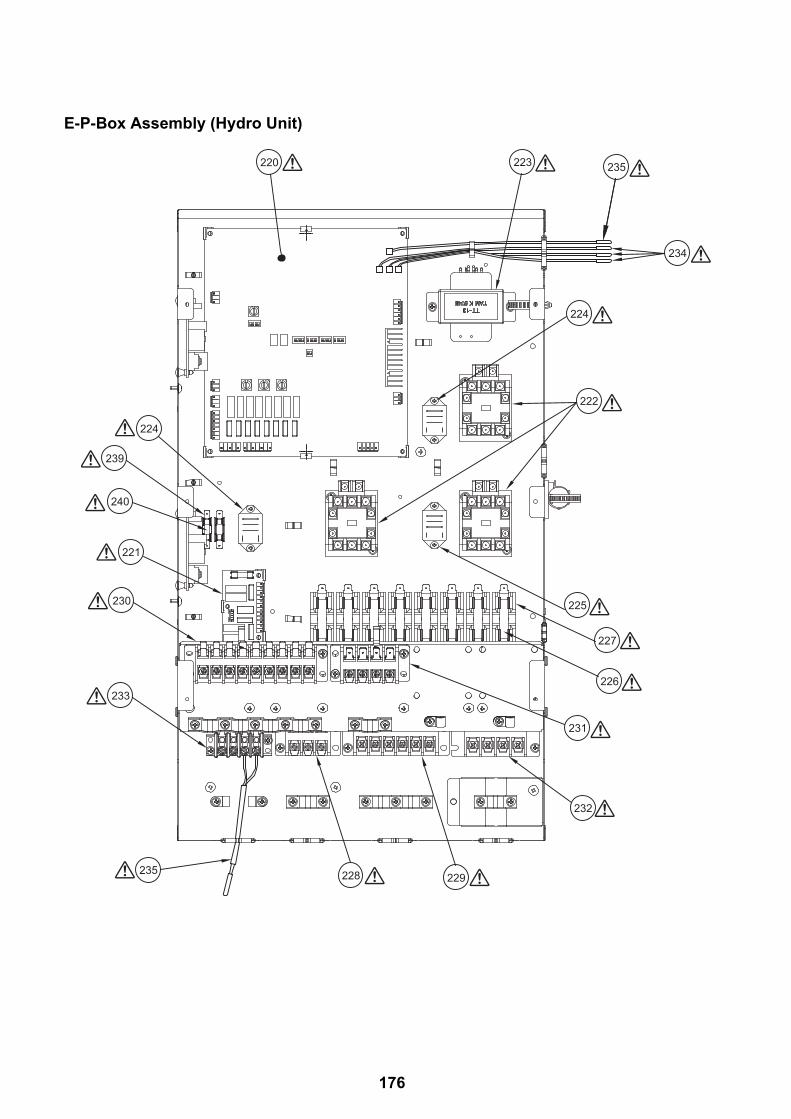
E-P-Box Assembly (Hydro Unit)
220
221
223
222
224
225
226
227
228 229
230
231
232
233
239
240
235
234
235
224
176
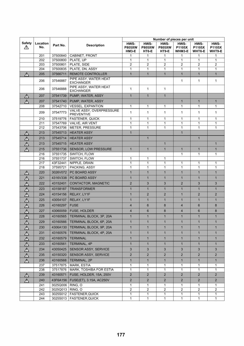
Safety Location No.
Part No. Description
Number of pieces per unitHWS-
P805XWHM3-E
HWS-P805XWHT6-E
HWS-P805XWHT9-E
HWS-P1105XWHM3-E
HWS-P1105XWHT6-E
HWS-P1105XWHT9-E
201 37500840 CABINET, FRONT 1 1 1 1 1 1202 37500800 PLATE, UP 1 1 1 1 1 1203 37500801 PLATE, SIDE 2 2 2 2 2 2204 37500835 PLATE, DN, ASSY 1 1 1 1 1 1
205 37566711 REMOTE CONTROLLER 1 1 1 1 1 1
206 37546887PIPE ASSY, WATER HEAT EXCHANGER
1 1 1
206 37546888PIPE ASSY, WATER HEAT EXCHANGER
1 1 1
207 37541739 PUMP, WATER, ASSY 1 1 1
207 37541740 PUMP, WATER, ASSY 1 1 1
208 37542710 VESSEL, EXPANTION 1 1 1 1 1 1
209 37547773VALVE ASSY, OVERPRESSURE PREVENTIVE
1 1 1 1 1 1
210 37519776 FASTENER, QUICK 1 1 1 1 1 1211 37547769 VALVE, AIR VENT 1 1 1 1 1 1212 37543706 METER, PRESSURE 1 1 1 1 1 1
213 37545713 HEATER ASSY 1 1
213 37545714 HEATER ASSY 1 1
213 37545715 HEATER ASSY 1 1
215 37551736 SENSOR, LOW PRESSURE 1 1 1 1 1 1
216 37551735 SWITCH, FLOW 1 1 1216 37551737 SWITCH, FLOW 1 1 1217 43F32441 NIPPLE, DRAIN 1 1 1 1 1 1218 37595721 PACKING, ASSY 1 1 1 1 1 1
220 3026V072 PC BOARD ASSY 1 1 1 1 1 1
221 4316V338 PC BOARD ASSY 1 1 1 1 1 1
222 43152401 CONTACTOR, MAGNETIC 2 3 3 2 3 3
223 43158187 TRANSFORMER 1 1 1 1 1 1
224 43154156 RELAY, LY1F 1 2 2 1 2 2
225 43054107 RELAY, LY1F 1 1 1 1 1 1
226 43160297 FUSE 4 6 8 4 6 8
227 43060059 FUSE, HOLDER 4 6 8 4 6 8
228 43160565 TERMINAL BLOCK, 3P, 20A 1 1 1 1 1 1
229 43160566 TERMINAL BLOCK, 6P, 20A 1 1 1 1 1 1
230 4306A130 TERMINAL BLOCK, 9P, 20A 1 1 1 1 1 1
231 43160576 TERMINAL BLOCK, 4P, 20A 1 1 1 1 1 1
232 43160579 TERMINAL 1 1 1 1 1 1
233 43160561 TERMINAL, 4P 1 1 1 1 1 1
234 43050425 SENSOR ASSY, SERVICE 3 3 3 3 3 3
235 43150320 SENSOR ASSY, SERVICE 2 2 2 2 2 2
236 43160568 TERMINAL, 2P 1 1 1 1 1 1
237 37517875 MARK, ESTIA 1 1 1 1 1 1238 37517876 MARK, TOSHIBA FOR ESTIA 1 1 1 1 1 1
239 43160571 FUSE, HOLDER, 15A, 250V 2 2 2 2 2 2
240 43F6A156 FUSE(ET), 3.15A, AC250V 2 2 2 2 2 2
241 3025Q006 RING, O 1 1 1 1 1 1242 3025Q013 RING, O 2 2 2 2 2 2243 3025S012 FASTENER,QUICK 1 1 1 1 1 1244 3025S013 FASTENER,QUICK 1 1 1 1 1 1
177
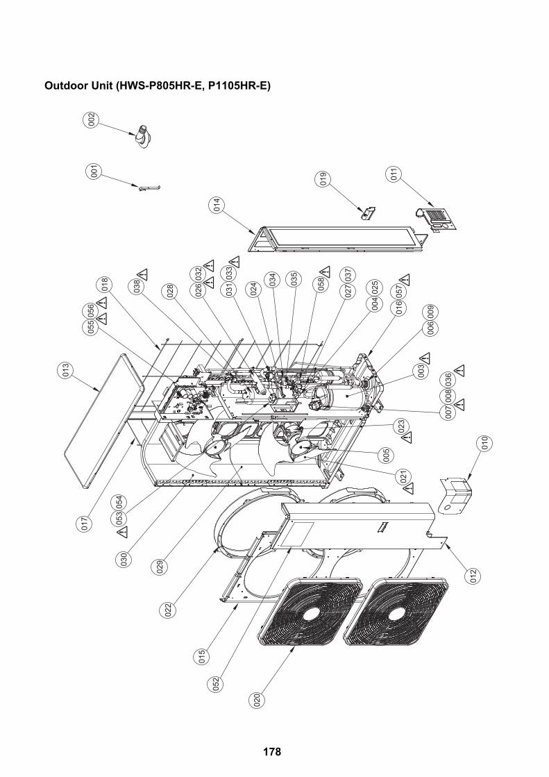
Outdoor Unit (HWS-P805HR-E, P1105HR-E)00
100
2
018
055
056
013
017
030
029
022
015
052
020
014
011
019
012
010
021
005
023
007
008
036
006
009016
05705
8
003
028
026
032
031
033
024 03
4
035
027
037
004
025
038
053
054
178

Safety Ref. No. Part No. Description
Number of pieces per unit
HWS-P805HR-E HWS-P1105HR-E
001 43F19904 HOLDER, SENSOR (TS) 3 3
002 43F32441 NIPPLE, DRAIN 1 1
003 43041794 COMPRESSOR, DA422A3F-25M 1 1
004 43F47246 BONNET, 3/8 IN 1 1
005 43F47669 NUT, FLANGE 2 2
006 43049739 CUSHION, RUBBER 3 3
007 43F50407 THERMOSTAT,BIMETAL 1 1
008 43F63317 HOLDER,THERMOSTAT 1 1
009 43F97212 NUT 3 3
010 43100437 PANEL, FRONT, PIPING 1 1
011 43100438 PANEL, BACK, PIPING 1 1
012 43100439 PANEL, FRONT 1 1
013 43100440 PLATE, ROOF 1 1
014 43100441 PANEL, SIDE 1 1
015 43100442 PANEL, AIR OUTLET 1 1
016 37500804 BASE ASSY 1 1
017 43107274 GUARD, FIN, SIDE 1 1
018 43107275 GUARD, FIN, BACK 1 1
019 43107276 HANGER 3 3
020 43119540 GUARD, FAN ASSY 2 2
021 43120244 FAN, PROPELLER, PB521 2 2
022 43122113 BELL MOUTH 2 2
023 4312C100 MOTOR, FAN, ICF-280-A100-1(A) 2 2
024 43146676 J0INT,CHECK 1 1
025 4314N092 VALVE, PACKED, 9.52 1 1
026 37546878 VALVE, 4-WAY, STF-H0404 1 1
027 43146724 VALVE, BALL, SBV-JA5GTC-1, R0HS 1 1
028 43148170 ACCUMULATOR ASS'Y 1 1
029 37546876 CONDENSER ASSY, DOWN 1 1
030 37546877 CONDENSER ASSY, UP 1 1
031 4314N023 VALVE, PLUS, MODULAING, UKV-25D100 1 1
032 37547768 COIL, VLVE, 4WAY, STF-H01AP1880A1 1 1
033 4314N025 COIL, PMV, UKV-A038 1 1
034 4314Q031 STRAINER 1 1
035 4314Q032 STRAINER 1 1
036 43160591 LEAD ASSY, COMPRESSOR 1 1
037 43194029 BONNET, 5/8 IN 1 1
038 37551741 SWITCH ASSY, PRESSURE ACB-4UB154W 1 1
052 37517891 MARK, TOSHIBA FOR ESTIA 1 1
053 4314N038 COIL, SOLENOID, AC220-240 50HZ 1 1
054 43146711 VALVE, 2WAY 1 1
055 43160571 FUSE, HOLDER, 15A, 250V 2 2
056 43F6A156 FUSE(ET), 3.15A, AC250V 2 2
057 37545716 HEATER ASSY 1 1
058 37550762 SENSOR ASSY, PRESSURE 1 1
179

Inverter Assembly (HWS-P805HR-E, P1105HR-E)
711709 710
705706
707
704
703
701
708
702
TD,TL
TS,TE,TO
TO
TE
180

Safety Ref. No. Part No. Description
Number of pieces per unit
HWS-P805HR-E HWS-P1105HR-E
701 43050425 SENSOR ASSY, SERVICE 3 3
702 43F63325 HOLDER, SENSOR (TE) 1 1
703 43150319 SENSOR ASSY, SERVICE 2 2
704 43158190 REACTOR 2 2
705 43160565 TERMINAL BLOCK, 3P, 20A 1 1
706 43160581 TERMINAL 1 1
707 43160589 FUSE 1 1
708 43163055 HOLDER, SENSOR 1 1
709 43163059 SPACER, BUSH 1 1
710 43163060 SPACER, COLLAR 1 1
711 3026V074 PC BOARD ASSY, MCC-1571 1 1
181

182

Copyright © 2017 TOSHIBA CARRIER CORPORATION, ALL Rights Reserved.