aircraft design 2011 1
TRANSCRIPT
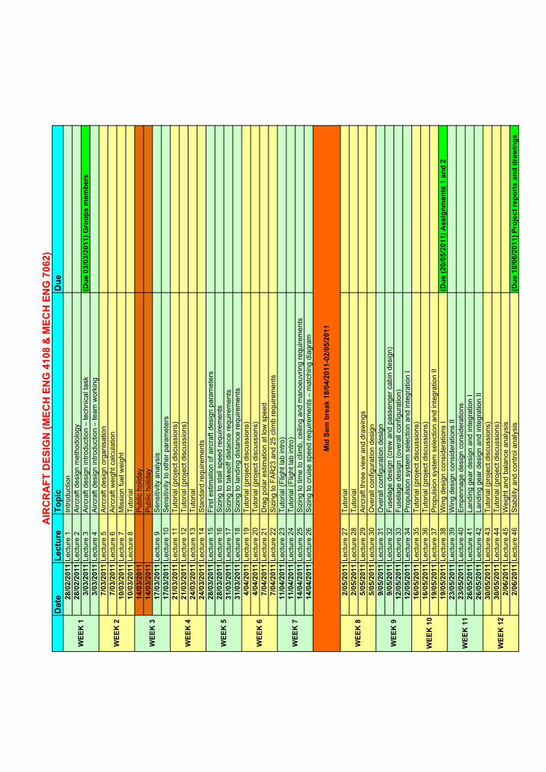
Date
Lecture
Topic
Due
28/02/2011Lecture 1
Introduction
28/02/2011Lecture 2
Aircraft design methodology
3/03/2011Lecture 3
Aircraft design introduction – technical task
(Due 03/03/2011) Groups members
3/03/2011Lecture 4
Aircraft design introduction – team working
7/03/2011Lecture 5
Aircraft design organisation
7/03/2011Lecture 6
Aircraft weight calculation
10/03/2011Lecture 7
Mission fuel weight
10/03/2011Lecture 8
Tutorial
14/03/2011
Public holiday
14/03/2011
Public holiday
17/03/2011Lecture 9
Sensitivity analysis
17/03/2011Lecture 10
Sensitivity to other parameters
21/03/2011Lecture 11
Tutorial (project discussions)
21/03/2011Lecture 12
Tutorial (project discussions)
24/03/2011Lecture 13
Tutorial
24/03/2011Lecture 14
Standard requirements
28/03/2011Lecture 15
First estimation of aircraft design parameters
28/03/2011Lecture 16
Sizing to stall speed requirements
31/03/2011Lecture 17
Sizing to takeoff distance requirements
31/03/2011Lecture 18
Sizing to landing distance requirements
4/04/2011Lecture 19
Tutorial (project discussions)
4/04/2011Lecture 20
Tutorial (project discussions)
7/04/2011Lecture 21
Drag polar estimation at low speed
7/04/2011Lecture 22
Sizing to FAR23 and 25 climb requirements
11/04/2011Lecture 23
Tutorial (Flight lab intro)
11/04/2011Lecture 24
Tutorial (Flight lab intro)
14/04/2011Lecture 25
Sizing to time to climb, ceiling and manoeuvring requirements
14/04/2011Lecture 26
Sizing to cruise speed requirements – matching diagram
2/05/2011Lecture 27
Tutorial
2/05/2011Lecture 28
Tutorial
5/05/2011Lecture 29
Aircraft three view and drawings
5/05/2011Lecture 30
Overall configuration design
9/05/2011Lecture 31
Overall configuration design
9/05/2011Lecture 32
Fuselage design (crew and passenger cabin design)
12/05/2011Lecture 33
Fuselage design (overall configuration)
12/05/2011Lecture 34
Propulsion system selection and integration I
16/05/2011Lecture 35
Tutorial (project discussions)
16/05/2011Lecture 36
Tutorial (project discussions)
19/05/2011Lecture 37
Propulsion system selection and integration II
19/05/2011Lecture 38
Wing design considerations I
(Due (20/05/2011) Assignments 1 and 2
23/05/2011Lecture 39
Wing design considerations II
23/05/2011Lecture 40
Empennage design considerations
26/05/2011Lecture 41
Landing gear design and integration I
26/05/2011Lecture 42
Landing gear design and integration II
30/05/2011Lecture 43
Tutorial (project discussions)
30/05/2011Lecture 44
Tutorial (project discussions)
2/06/2011Lecture 45
Weight and balance analysis
2/06/2011Lecture 46
Stability and control analysis
(Due 10/06/2011) Project reports and drawings
Mid Sem break 18/04/2011-02/05/2011
WEEK 7
WEEK 8
WEEK 9
WEEK 10
WEEK 12
AIRCRAFT DESIGN (MECH ENG 4108 & MECH ENG 7062)
WEEK 5
WEEK 6
WEEK 11
WEEK 1
WEEK 2
WEEK 3
WEEK 4
School of Mechanical EngineeringAircraft Design
Introduction
Dr. MAZIAR ARJOMANDI
Semester I
Introduction Copyright - The University of Adelaide Slide Number 1
Semester I
Aircraft Design School of Mechanical Engineering
About myself:
• Education:
– PhD in Aerospace Engineering (Aircraft Design) from Moscow Aviation Institute (MAI), 1999
– ME in Aerospace Engineering (Aircraft Design) from Moscow Aviation Institute (MAI),1996
– BE in Mechanical Engineering (Design) from Iran University of Science and Technology
(IUST), 1992
• Research Area:– Optimization techniques in aircraft conceptual design
– Aircraft design
– Active and passive methods of flow control
– Plasma aerodynamics
– Vortex flow
– Heat transfer
– UAV and MAV design
Introduction Copyright - The University of Adelaide Slide Number 2
– UAV and MAV design
– Composite materials
– Sustainable energy production
– Wind and wave energy devices
• Contacts:
– Room S232, email: [email protected], phone: 83038128
– Webpage: http://www.mecheng.adelaide.edu.au/~marjom01/
Page 1 of 270
Aircraft Design School of Mechanical Engineering
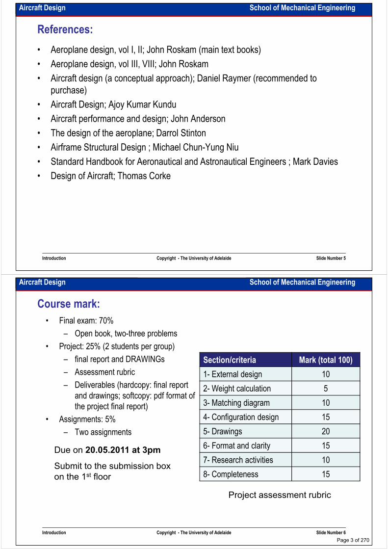
What we are trying to do in this course:
• In Teaching Aircraft design, we require students, either individually or in small
groups do engineering.
Course objectives:
• Design process
• Engineering methods in real life (this is not the same thing as calculation)
• Engineering teamwork and projects (with individual responsibility in a
Introduction Copyright - The University of Adelaide Slide Number 3
• Engineering teamwork and projects (with individual responsibility in a group)
• Aeroplane design (what we really signed up to do)
Aircraft Design School of Mechanical Engineering
1. Design an aircraft using the design process.
2. Use design requirement to define specific aircraft configuration features.
3. Estimate aircraft size, weight and thrust required to satisfy mission requirements.
Course specific objectives:
4. Do an engineering analysis to assess an aircraft design’s potential to meet given design requirements.
5. Compile data, compare and assess current aircraft capabilities against a specific design requirement.
6. Make pro/con charts comparing design concepts against the desired design matrix.
7. Do parametric analysis to select design variable values.
8. Work on a multidisciplinary design team.
Introduction Copyright - The University of Adelaide Slide Number 4
8. Work on a multidisciplinary design team.
9. Write an engineering design report.
Page 2 of 270
Aircraft Design School of Mechanical Engineering
References:
• Aeroplane design, vol I, II; John Roskam (main text books)
• Aeroplane design, vol III, VIII; John Roskam
• Aircraft design (a conceptual approach); Daniel Raymer (recommended to
purchase)purchase)
• Aircraft Design; Ajoy Kumar Kundu
• Aircraft performance and design; John Anderson
• The design of the aeroplane; Darrol Stinton
• Airframe Structural Design ; Michael Chun-Yung Niu
• Standard Handbook for Aeronautical and Astronautical Engineers ; Mark Davies
• Design of Aircraft; Thomas Corke
Introduction Copyright - The University of Adelaide Slide Number 5
Aircraft Design School of Mechanical Engineering
Course mark:
• Final exam: 70%
– Open book, two-three problems
• Project: 25% (2 students per group)
– final report and DRAWINGs
– Assessment rubric
Section/criteria Mark (total 100)
– Assessment rubric
– Deliverables (hardcopy: final report
and drawings; softcopy: pdf format of
the project final report)
• Assignments: 5%
– Two assignments
Due on 20.05.2011 at 3pm
1- External design 10
2- Weight calculation 5
3- Matching diagram 10
4- Configuration design 15
5- Drawings 20
6- Format and clarity 15
7- Research activities 10
Introduction Copyright - The University of Adelaide Slide Number 6
Submit to the submission box
on the 1st floor
Project assessment rubric
7- Research activities 10
8- Completeness 15
Page 3 of 270

Aircraft Design School of Mechanical Engineering
Intentionally left blank for your notes
……………………………………………………………………………………………………
……………………………………………………………………………………………………
……………………………………………………………………………………………………
……………………………………………………………………………………………………
…………………………………………………………………………………………………………………………………………………………………………………………………………
……………………………………………………………………………………………………
……………………………………………………………………………………………………
……………………………………………………………………………………………………
……………………………………………………………………………………………………
……………………………………………………………………………………………………
……………………………………………………………………………………………………
……………………………………………………………………………………………………
Introduction Copyright - The University of Adelaide Slide Number 7
……………………………………………………………………………………………………
……………………………………………………………………………………………………
……………………………………………………………………………………………………
……………………………………………………………………………………………………
……………………………………………………………………………………………………
…………………………………………………………………………………………………….
Aircraft Design School of Mechanical Engineering
Aerospace internationalisation
• International business competitions
– Airbus is competing with Boeing
– Russia is trying to join EADS to be in competition
– Japan, China and India are entering the aerospace business
– Australia is reinforcing its joint venture with US and British aerospace industries
• Too expensive to be afforded by one country
• Major political influences
• High added value products
• Most prestigious industry
• Related to safeguarding the countries
Introduction Copyright - The University of Adelaide Slide Number 8
Page 4 of 270
Aircraft Design School of Mechanical Engineering
Who is a good designer?
• Always asking questions, curiosity about everything
• Great associative power: lets them recognize and draw upon parallels in other fields for ideas (implies that designers have eclectic interests and often roam for a field in science and engineering - said to be “interested in everything.”)
• Presented with a problem, always seem to respond with a flood of ideas, then look • Presented with a problem, always seem to respond with a flood of ideas, then look to interactions with associates to sort out the good from the bad
• Strong inner directed personalities: are sure of themselves, able to accept with equanimity the guffaws at the poor solutions they propose along with the kudos for success
Introduction Copyright - The University of Adelaide Slide Number 9
Aircraft Design School of Mechanical Engineering
Computer & designer relationship:
“New engineers today have an overdependence on computers. They have a tendency to believe
everything the computers tell them. You throw in a bunch of numbers and out comes the
answer, and therefore it must be right. Just because it comes out on a computer printout
doesn’t make it right.
I should be able to go to a wing designer and say to him or her, “We need to change the gross
weight by 5%. How does that change the bending moment of the new wing?” If that person
runs a calculation on the back of the envelope and says it’ll do this, that’s fine with me. But
when someone says I’ll give you the answer in three days when it comes out of the
computer, that’s an overdependence.
You’ve got to have practical thinking people who know what they’re doing.”
Introduction Copyright - The University of Adelaide Slide Number 10
From Benjamin Cosgrove (Boeing Head Engineer)
Page 5 of 270
Aircraft Design School of Mechanical Engineering
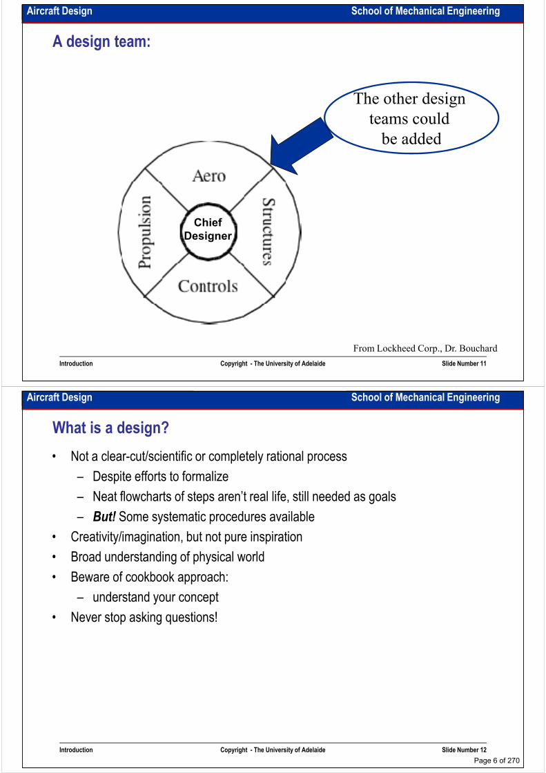
A design team:
The other design
teams could
be added
Chief
Designer
be added
Introduction Copyright - The University of Adelaide Slide Number 11
From Lockheed Corp., Dr. Bouchard
Aircraft Design School of Mechanical Engineering
What is a design?
• Not a clear-cut/scientific or completely rational process
– Despite efforts to formalize
– Neat flowcharts of steps aren’t real life, still needed as goals
– But! Some systematic procedures available– But! Some systematic procedures available
• Creativity/imagination, but not pure inspiration
• Broad understanding of physical world
• Beware of cookbook approach:
– understand your concept
• Never stop asking questions!
Introduction Copyright - The University of Adelaide Slide Number 12
Page 6 of 270
Aircraft Design School of Mechanical Engineering
Type of design:
• Selection (“catalogue design”)
• Configuration (assembly of selections)
• Parametric (how big is the wing?)
• Original (What could be called conceptual design)• Original (What could be called conceptual design)
• Redesign (new versions, improvements, etc.)
Introduction Copyright - The University of Adelaide Slide Number 13
Most design projects use several of these types of design
Aircraft Design School of Mechanical Engineering
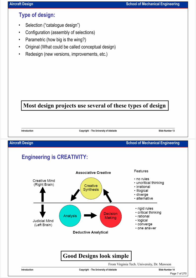
Engineering is CREATIVITY:
Introduction Copyright - The University of Adelaide Slide Number 14
From Virginia Tech. University, Dr. Mawson
Good Designs look simple
Page 7 of 270
Aircraft Design School of Mechanical Engineering
An engineering design approach:
• evaluate (or define) the requirements (customers/regulations, constraints/performance
goals)
• understand current approaches (what’s done now?)
• think of some possible solutions (creativity)• think of some possible solutions (creativity)
• identify a variety of possible concepts (concept generation)
• concept evaluation (analysis)
• select a preferred concept for development (make a decision)
• do the detail design and make a prototype (analysis)
• test and evaluate (scrutinise)
• continually refine the design until it’s a viable product
Introduction Copyright - The University of Adelaide Slide Number 15
Note: Many of these steps are repeated, it’s an iterative process
Aircraft Design School of Mechanical Engineering
Some facts
1. Visualization may be more important than analysis
Quality sketches/drawings critically important
2. The design engineer who remains on the frontiers of engineering finds himself 2. The design engineer who remains on the frontiers of engineering finds himself
making only a small fraction of his decisions on the basis of numerical analysis:
but understanding fundamental principles is crucial
3. Failures: Only a small fraction of engineering design failures would have been
prevented using advanced numerical methods.
Introduction Copyright - The University of Adelaide Slide Number 16
Page 8 of 270

School of Mechanical EngineeringAircraft Design
Aircraft design methodology
Dr. MAZIAR ARJOMANDI
Semester I
Aircraft design methodology Copyright - The University of Adelaide Slide Number 1
Semester I
Aircraft Design School of Mechanical Engineering
Design as decision making:
• Design is a net decision making process
• Decisions could be very expensive “you bet your company”:
– Airbus A380 vs B747X
– SU-27 (Supermanoeuvrability) vs F-16 (simplicity)– SU-27 (Supermanoeuvrability) vs F-16 (simplicity)
– Military bets: the JSF, winner takes all
• Design decisions make at every level:
– what’s the wing planform?
– which airfoil?
– what materials?
– balance - stable or unstable?
• To support the design decisions we use :
Aircraft design methodology Copyright - The University of Adelaide Slide Number 2
• To support the design decisions we use :
– Multidisciplinary Design Optimisation (MDO)
– tables of pros and cons
– relevant experience, observation of prior practice, case study
– education
– team working
Page 9 of 270
Aircraft Design School of Mechanical Engineering
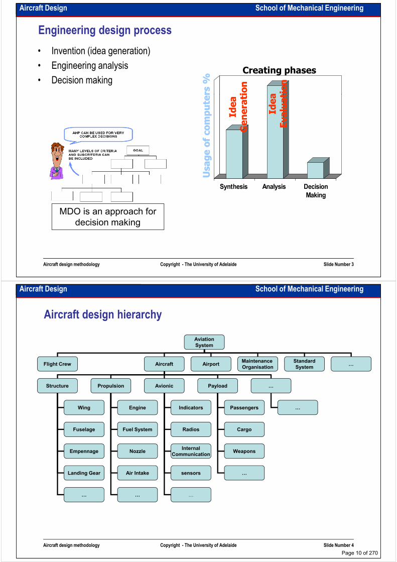
Engineering design process
• Invention (idea generation)
• Engineering analysis
• Decision making
Usage of computers %
Usage of computers %
Idea
Idea
Evaluation
Evaluation
Idea
Idea
Generation
Generation
Creating phases
Synthesis Analysis Decision
Usage of computers %
Usage of computers %
Idea
Idea
Evaluation
Evaluation
Idea
Idea
Generation
Generation
Aircraft design methodology Copyright - The University of Adelaide Slide Number 3
Synthesis Analysis Decision
Making
MDO is an approach for
decision making
Aircraft Design School of Mechanical Engineering
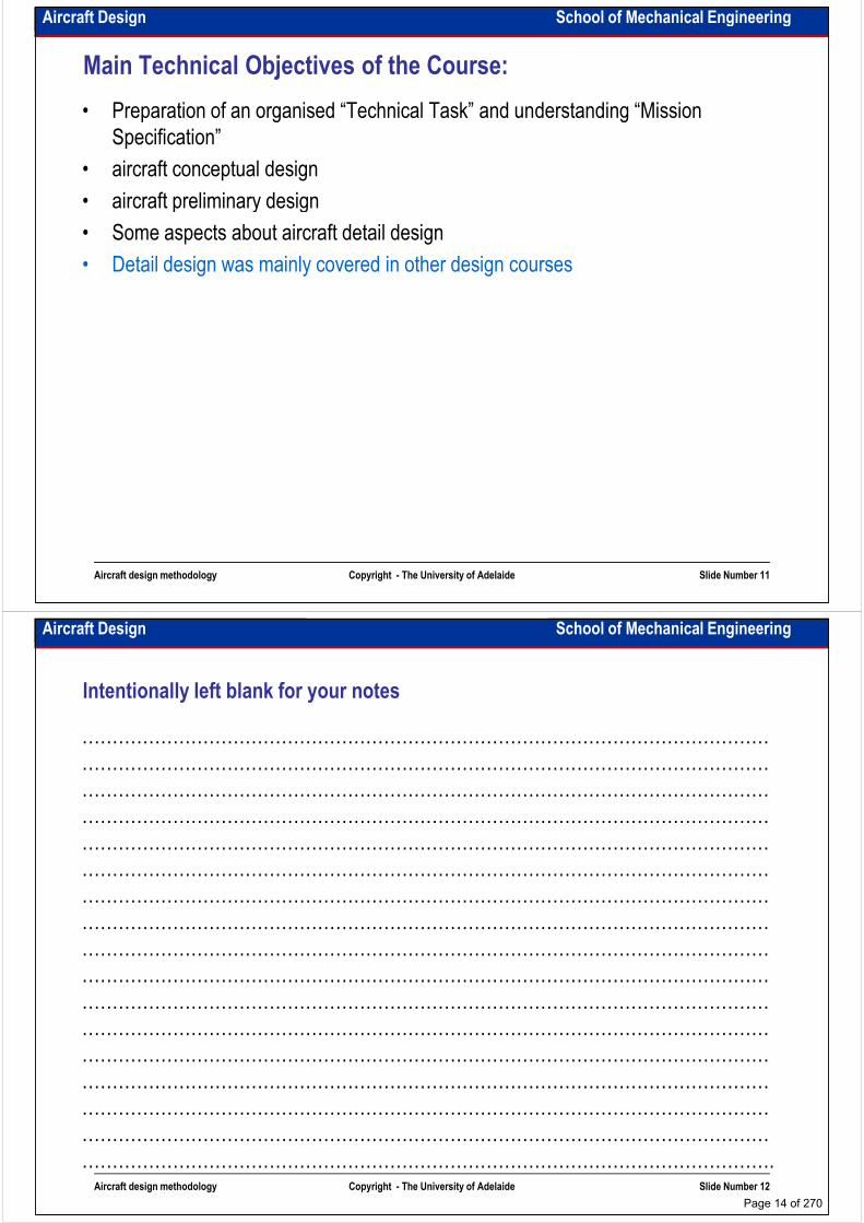
Aircraft design hierarchy
Aviation
System
Flight Crew AirportMaintenance
OrganisationAircraft
Standard
System…
Structure Propulsion Avionic Payload …
Wing
Fuselage
Empennage
Engine
Fuel System
Nozzle
Indicators
Radios
Internal
Communication
Passengers
Cargo
Weapons
…
Aircraft design methodology Copyright - The University of Adelaide Slide Number 4
Landing Gear Air Intake sensors …
…… …
Page 10 of 270

Aircraft Design School of Mechanical Engineering
Aircraft Design process:
External DesignPreparation the
requirements
Request For Proposal (RFP)
Technical Task (TT)
Internal Design
requirements
Design
Conceptual Design
Preliminary Design
Detail Design (Prototyping
& Flight Testing & …)
Tooling
Aircraft design methodology Copyright - The University of Adelaide Slide Number 5
Manufacturing ManufacturingTooling
Mass production
Aircraft Design School of Mechanical Engineering
Design stages:
• Conceptual Design (1-3% of the people)
– Competing concepts are evaluated
– Performance goals are established
– Preferred concept is selected– Preferred concept is selected
– What drives the design?
– Will it works?
– Will it meet the requirements?
– What does it look like?
Aircraft design methodology Copyright - The University of Adelaide Slide Number 6
Page 11 of 270

Aircraft Design School of Mechanical Engineering
Design stages:
• Preliminary Design (10-15% of the people)
– Refined sizing of preferred concept is done
– Design is examined (establish confidence)
– Some wind tunnel tests are done– Some wind tunnel tests are done
– Big codes are used
– Actual cost estimation is prepared
– changes are allowed
– Company is involved
Aircraft design methodology Copyright - The University of Adelaide Slide Number 7
Aircraft Design School of Mechanical Engineering
Design stages:
• Detail Design (80-90% of the people)
– Final detail design is done
– Drawings are released
– Detailed performance is calculated– Detailed performance is calculated
– Certification process is started
– Component and system tests are conducted
– Tooling design is started
– More and precise wind tunnel tests are done
– Prototypes are manufactured
– Flight tests are done
Aircraft design methodology Copyright - The University of Adelaide Slide Number 8
– Flight tests are done
– Only “tweaking” of design is allowed
Page 12 of 270

Aircraft Design School of Mechanical Engineering
Design and costs
Funds committed
Decisions made
Aircraft design methodology Copyright - The University of Adelaide Slide Number 9
Aircraft Design School of Mechanical Engineering
Aircraft development process
Aircraft design methodology Copyright - The University of Adelaide Slide Number 10
From aeroplane design, past, present and future by Prof. McMaser (Boeing Co)
Page 13 of 270
Aircraft Design School of Mechanical Engineering
Main Technical Objectives of the Course:
• Preparation of an organised “Technical Task” and understanding “Mission
Specification”
• aircraft conceptual design
• aircraft preliminary design• aircraft preliminary design
• Some aspects about aircraft detail design
• Detail design was mainly covered in other design courses
Aircraft design methodology Copyright - The University of Adelaide Slide Number 11
Aircraft Design School of Mechanical Engineering
Intentionally left blank for your notes
……………………………………………………………………………………………………
……………………………………………………………………………………………………
……………………………………………………………………………………………………
…………………………………………………………………………………………………………………………………………………………………………………………………………
……………………………………………………………………………………………………
……………………………………………………………………………………………………
……………………………………………………………………………………………………
……………………………………………………………………………………………………
……………………………………………………………………………………………………
……………………………………………………………………………………………………
……………………………………………………………………………………………………
……………………………………………………………………………………………………
Aircraft design methodology Copyright - The University of Adelaide Slide Number 12
……………………………………………………………………………………………………
……………………………………………………………………………………………………
……………………………………………………………………………………………………
……………………………………………………………………………………………………
……………………………………………………………………………………………………
…………………………………………………………………………………………………….
Page 14 of 270

School of Mechanical EngineeringAircraft Design
Aircraft design introduction – technical taskAircraft design introduction – technical task
Dr. MAZIAR ARJOMANDI
Semester I
Aircraft design introduction –
technical task
Copyright - The University of Adelaide Slide Number 1
Semester I
Aircraft Design School of Mechanical Engineering
Understanding mission specification:
• Market survey
• Operational analysis
• Customer requirements
• Economical manufacturing and design• Economical manufacturing and design
• Reliability considerations
• Maintainability considerations
• Flexible design (could be slightly changed in design process)
• Continual improvement (development of a family of products)
Aircraft design introduction –
technical task
Copyright - The University of Adelaide Slide Number 2
The requirements should be realistic, practical and reasonable
Page 15 of 270
Aircraft Design School of Mechanical Engineering
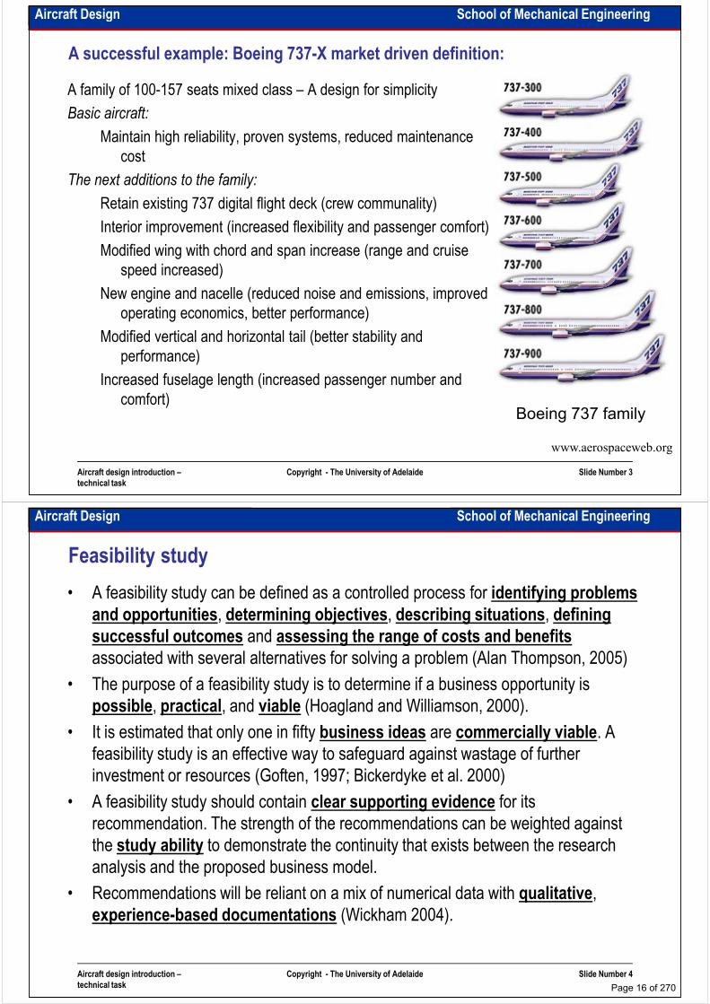
A successful example: Boeing 737-X market driven definition:
A family of 100-157 seats mixed class – A design for simplicity
Basic aircraft:
Maintain high reliability, proven systems, reduced maintenance
cost
The next additions to the family:
Retain existing 737 digital flight deck (crew communality)
Interior improvement (increased flexibility and passenger comfort)
Modified wing with chord and span increase (range and cruise
speed increased)
New engine and nacelle (reduced noise and emissions, improved
operating economics, better performance)
Modified vertical and horizontal tail (better stability and
Aircraft design introduction –
technical task
Copyright - The University of Adelaide Slide Number 3
Modified vertical and horizontal tail (better stability and
performance)
Increased fuselage length (increased passenger number and
comfort)
www.aerospaceweb.org
Boeing 737 family
Aircraft Design School of Mechanical Engineering
Feasibility study
• A feasibility study can be defined as a controlled process for identifying problems
and opportunities, determining objectives, describing situations, defining
successful outcomes and assessing the range of costs and benefits
associated with several alternatives for solving a problem (Alan Thompson, 2005)
• The purpose of a feasibility study is to determine if a business opportunity is
possible, practical, and viable (Hoagland and Williamson, 2000).
• It is estimated that only one in fifty business ideas are commercially viable. A
feasibility study is an effective way to safeguard against wastage of further
investment or resources (Goften, 1997; Bickerdyke et al. 2000)
• A feasibility study should contain clear supporting evidence for its
recommendation. The strength of the recommendations can be weighted against
Aircraft design introduction –
technical task
Copyright - The University of Adelaide Slide Number 4
the study ability to demonstrate the continuity that exists between the research
analysis and the proposed business model.
• Recommendations will be reliant on a mix of numerical data with qualitative,
experience-based documentations (Wickham 2004).
Page 16 of 270
Aircraft Design School of Mechanical Engineering
Feasibility study
Aircraft design introduction –
technical task
Copyright - The University of Adelaide Slide Number 5
www.cartoonstock.com
Aircraft Design School of Mechanical Engineering
Feasibility study discussions
It is not a literature survey or benchmarkingIt is not a literature survey or benchmarkingIt is not a literature survey or benchmarkingIt is not a literature survey or benchmarking
The topics are:
• What is the product (benchmarking)?
• Technology required (literature survey)?
• Market environment?
• Who are the competitors?
• Industries involved?
• Intellectual property?
• Regulations and standards?
• Environmental issues?
• Critical risk factors and mitigation
strategy?
• Financial issues?
Aircraft design introduction –
technical task
Copyright - The University of Adelaide Slide Number 6
• Business model required?
• Marketing and sales strategy?
• Production facilities?
• Operating and maintenance organisations?
• Financial issues?
Page 17 of 270
Aircraft Design School of Mechanical Engineering
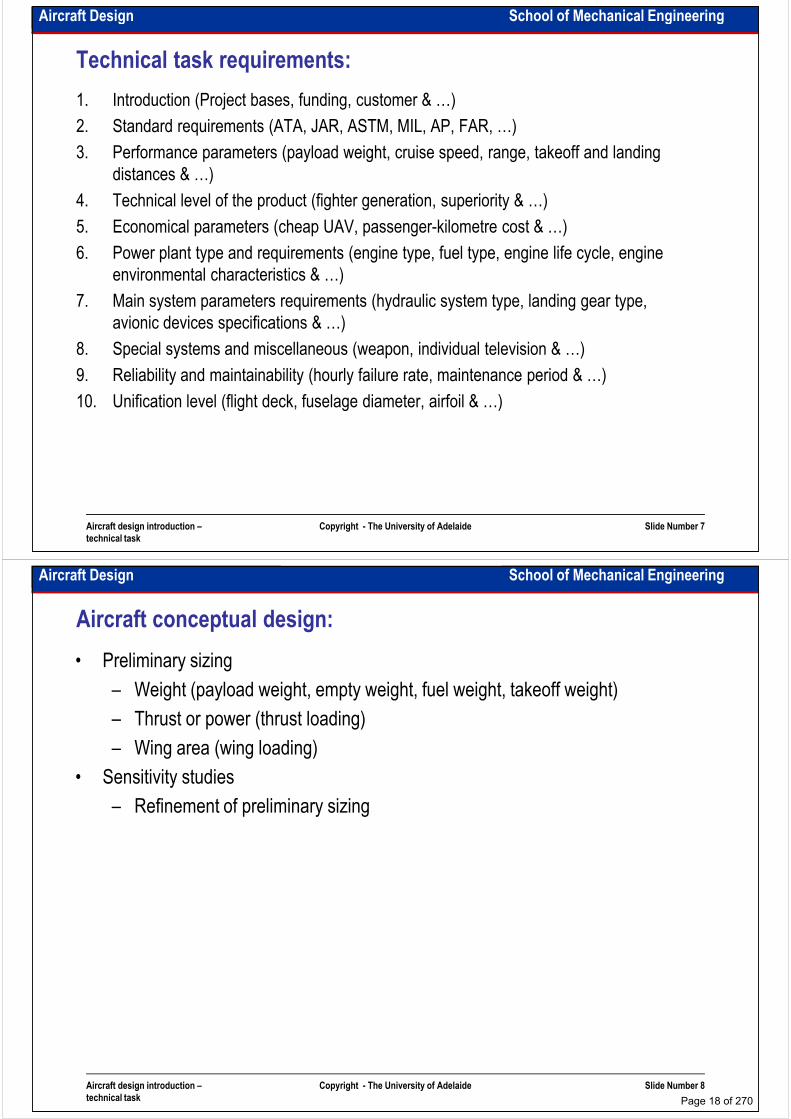
Technical task requirements:
1. Introduction (Project bases, funding, customer & …)
2. Standard requirements (ATA, JAR, ASTM, MIL, AP, FAR, …)
3. Performance parameters (payload weight, cruise speed, range, takeoff and landing
distances & …)
4. Technical level of the product (fighter generation, superiority & …)
5. Economical parameters (cheap UAV, passenger-kilometre cost & …)
6. Power plant type and requirements (engine type, fuel type, engine life cycle, engine
environmental characteristics & …)
7. Main system parameters requirements (hydraulic system type, landing gear type,
avionic devices specifications & …)
8. Special systems and miscellaneous (weapon, individual television & …)
9. Reliability and maintainability (hourly failure rate, maintenance period & …)
Aircraft design introduction –
technical task
Copyright - The University of Adelaide Slide Number 7
9. Reliability and maintainability (hourly failure rate, maintenance period & …)
10. Unification level (flight deck, fuselage diameter, airfoil & …)
Aircraft Design School of Mechanical Engineering
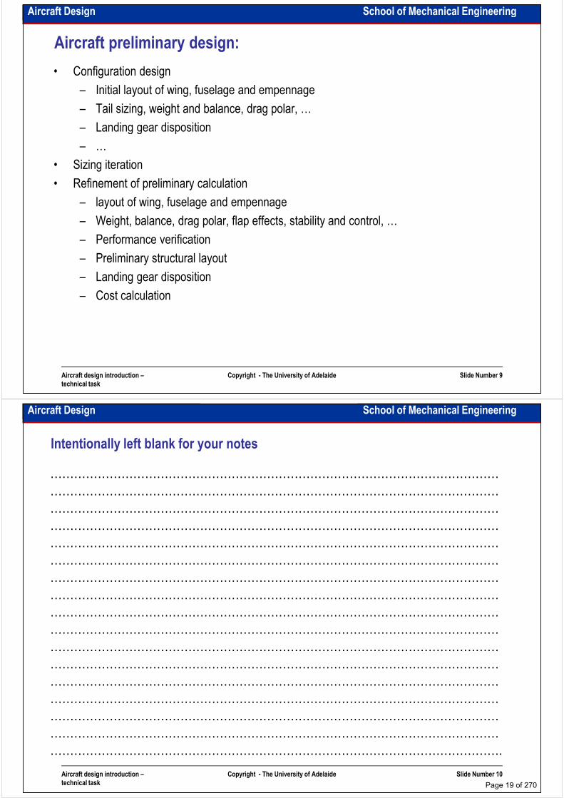
Aircraft conceptual design:
• Preliminary sizing
– Weight (payload weight, empty weight, fuel weight, takeoff weight)
– Thrust or power (thrust loading)
– Wing area (wing loading)– Wing area (wing loading)
• Sensitivity studies
– Refinement of preliminary sizing
Aircraft design introduction –
technical task
Copyright - The University of Adelaide Slide Number 8
Page 18 of 270
Aircraft Design School of Mechanical Engineering
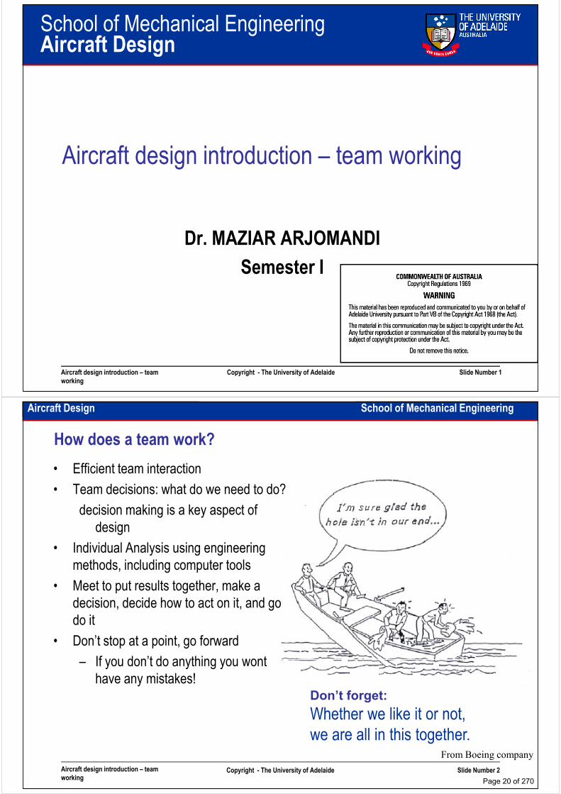
Aircraft preliminary design:
• Configuration design
– Initial layout of wing, fuselage and empennage
– Tail sizing, weight and balance, drag polar, …
– Landing gear disposition
– …
• Sizing iteration
• Refinement of preliminary calculation
– layout of wing, fuselage and empennage
– Weight, balance, drag polar, flap effects, stability and control, …
– Performance verification
– Preliminary structural layout
Aircraft design introduction –
technical task
Copyright - The University of Adelaide Slide Number 9
– Preliminary structural layout
– Landing gear disposition
– Cost calculation
Aircraft Design School of Mechanical Engineering
Intentionally left blank for your notes
……………………………………………………………………………………………………
……………………………………………………………………………………………………
……………………………………………………………………………………………………
……………………………………………………………………………………………………
……………………………………………………………………………………………………
……………………………………………………………………………………………………
……………………………………………………………………………………………………
……………………………………………………………………………………………………
……………………………………………………………………………………………………
……………………………………………………………………………………………………
……………………………………………………………………………………………………
……………………………………………………………………………………………………
Aircraft design introduction –
technical task
Copyright - The University of Adelaide Slide Number 10
……………………………………………………………………………………………………
……………………………………………………………………………………………………
……………………………………………………………………………………………………
……………………………………………………………………………………………………
……………………………………………………………………………………………………
…………………………………………………………………………………………………….
Page 19 of 270
School of Mechanical EngineeringAircraft Design
Aircraft design introduction – team working
Dr. MAZIAR ARJOMANDI
Semester I
Aircraft design introduction – team
working
Copyright - The University of Adelaide Slide Number 1
Semester I
Aircraft Design School of Mechanical Engineering
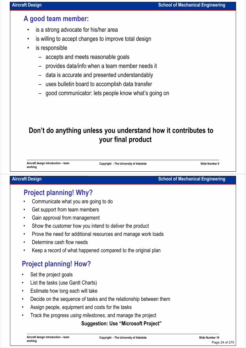
How does a team work?
• Efficient team interaction
• Team decisions: what do we need to do?
decision making is a key aspect of
designdesign
• Individual Analysis using engineering
methods, including computer tools
• Meet to put results together, make a
decision, decide how to act on it, and go
do it
• Don’t stop at a point, go forward
– If you don’t do anything you wont
Aircraft design introduction – team
workingCopyright - The University of Adelaide Slide Number 2
– If you don’t do anything you wont
have any mistakes!
From Boeing company
Don’t forget:
Whether we like it or not,
we are all in this together.
Page 20 of 270

Aircraft Design School of Mechanical Engineering
What is teamwork?
• It is not everyone getting together to work on the same homework problem.
• It is:
– establishing the question that needs to be answeredbe answered
– each team member taking responsibility for a particular task and doing the work
– putting the results of each task together at a group meeting and establishing: Did we answer the question?
– If so, what's next? If not, how do we recast the question?
Aircraft design introduction – team
workingCopyright - The University of Adelaide Slide Number 3
www.cartoonstock.com
Aircraft Design School of Mechanical Engineering
How a productive team works:
Aircraft design introduction – team
workingCopyright - The University of Adelaide Slide Number 4
From Book: Building productive teams by Varney
Page 21 of 270

Aircraft Design School of Mechanical Engineering
What is an effective team?
1. Atmosphere - informal, relaxed, comfortable
2. All members participate in discussion
3. Objective of the team is well understood/accepted
4. Members listen to each other
1. Atmosphere of indifference/boredom or tension/antagonism
2. A few team members dominate
3. An observer has a hard time understanding team objectives
What is an ineffective team?
4. Members listen to each other
5. There is disagreement, but group accepts it
6. Most decisions reached by a kind of consensus
7. Criticism is frequent, frank, constructive; not personal
8. Members feel free to express feelings as well as ideas
9. Action: assignments are clear and accepted
team objectives
4. Team members do not listen, discussion jumps around
5. Disagreement not dealt with effectively
6. Actions taken prematurely, before real issues resolved
7. Action: unclear—what is to be done and who does it?
8. Leadership clear, whether weak or strong
Aircraft design introduction – team
workingCopyright - The University of Adelaide Slide Number 5
9. Action: assignments are clear and accepted
10. Leader does not dominate
11. Group evaluates operation, resolves problems
From Book: Team players and Teamwork by Parker
8. Leadership clear, whether weak or strong
9. Criticism appears embarrassing and tension-producing
10. Personal feelings are hidden
11. Group does not examine its performance/process
Aircraft Design School of Mechanical Engineering
Effective teams contain a mix of personalities:
• Contributor: task oriented, enjoys providing team with good information, does
homework, pushes excellence
• Collaborator: goal-directed, sees team mission/goals, but willing to help outside
his/her defined role, share limelight with other team members, seen as a “big-his/her defined role, share limelight with other team members, seen as a “big-
picture” person
• Communicator: process-oriented, effective listener and facilitator; consensus
builder, resolves conflicts, seen as a “people person”
• Challenger: questions goals and methods, willing to disagree, encourages team to
take well-conceived risks.
Aircraft design introduction – team
workingCopyright - The University of Adelaide Slide Number 6
From Book: Team players and Teamwork by Parker
Page 22 of 270

Aircraft Design School of Mechanical Engineering
Code of Cooperation for teams:
1. EVERY member is responsible for the team’s
progress and success.
2. Attend all team meetings and be on time.
3. Carry out assignments on schedule.
4. Listen to and show respect for the views of other
members.
5. Criticize ideas, not persons.
6. Use and expect constructive feedback.
7. Resolve conflicts constructively.
8. Always strive for win-win situations.
9. Pay attention — avoid disruptive behaviour.
10. Ask questions when you do not understand
Aircraft design introduction – team
workingCopyright - The University of Adelaide Slide Number 7
10. Ask questions when you do not understand
http://www.searchenginepeople.com
From Boeing Commercial Airplane Group by Don Evans
Aircraft Design School of Mechanical Engineering
What is teamwork?
Aircraft design introduction – team
workingCopyright - The University of Adelaide Slide Number 8
www.popular-pics.com
Page 23 of 270
Aircraft Design School of Mechanical Engineering
A good team member:
• is a strong advocate for his/her area
• is willing to accept changes to improve total design
• is responsible
– accepts and meets reasonable goals– accepts and meets reasonable goals
– provides data/info when a team member needs it
– data is accurate and presented understandably
– uses bulletin board to accomplish data transfer
– good communicator: lets people know what’s going on
Aircraft design introduction – team
workingCopyright - The University of Adelaide Slide Number 9
Don’t do anything unless you understand how it contributes to
your final product
Aircraft Design School of Mechanical Engineering
Project planning! Why?• Communicate what you are going to do
• Get support from team members
• Gain approval from management
• Show the customer how you intend to deliver the product
• Prove the need for additional resources and manage work loads• Prove the need for additional resources and manage work loads
• Determine cash flow needs
• Keep a record of what happened compared to the original plan
Project planning! How?
• Set the project goals
• List the tasks (use Gantt Charts)
• Estimate how long each will take
Aircraft design introduction – team
workingCopyright - The University of Adelaide Slide Number 10
• Estimate how long each will take
• Decide on the sequence of tasks and the relationship between them
• Assign people, equipment and costs for the tasks
• Track the progress using milestones, and manage the project
Suggestion: Use “Microsoft Project”
Page 24 of 270
Aircraft Design School of Mechanical Engineering
Project planning
Aircraft design introduction – team
workingCopyright - The University of Adelaide Slide Number 11
www.glasbergen.com
Aircraft Design School of Mechanical Engineering
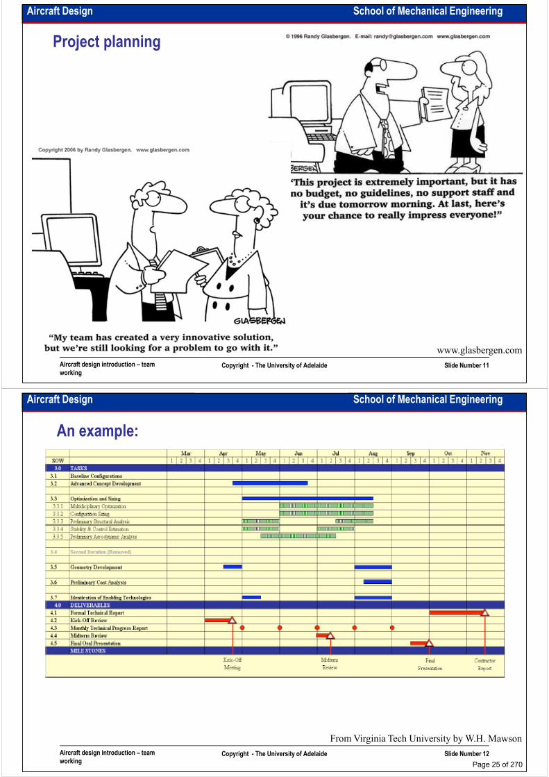
An example:
Aircraft design introduction – team
workingCopyright - The University of Adelaide Slide Number 12
From Virginia Tech University by W.H. Mawson
Page 25 of 270

Aircraft Design School of Mechanical Engineering
Time management:
• List everything you need to do today - in order of priority.
• Make time for important things, not just urgent ones.
• Write your goals. Then write the steps to your goals.
• Set a starting time as well as a deadline for all projects.• Set a starting time as well as a deadline for all projects.
• Slice up big projects into bite-size pieces
• If you run out of steam on one project, switch to another
• Say no to new projects when you’re already overloaded
• Trim low-payoff activities from your schedule
• For each paper that crosses your desk: act on it, file it, or
toss it
Aircraft design introduction – team
workingCopyright - The University of Adelaide Slide Number 13
www.cartoonstock.com
Aircraft Design School of Mechanical Engineering
Intentionally left blank for your notes
………………………………………………………………………………………………
………………………………………………………………………………………………
………………………………………………………………………………………………
………………………………………………………………………………………………
………………………………………………………………………………………………………………………………………………………………………………………………
………………………………………………………………………………………………
………………………………………………………………………………………………
………………………………………………………………………………………………
………………………………………………………………………………………………
………………………………………………………………………………………………
………………………………………………………………………………………………
………………………………………………………………………………………………
………………………………………………………………………………………………
Aircraft design introduction – team
workingCopyright - The University of Adelaide Slide Number 14
………………………………………………………………………………………………
………………………………………………………………………………………………
………………………………………………………………………………………………
………………………………………………………………………………………………
………………………………………………………………………………………………
………………………………………………………………………………………….
Page 26 of 270
School of Mechanical EngineeringAircraft Design
Aircraft design organisation
Dr. MAZIAR ARJOMANDI
Semester I
Aircraft design organisation Copyright - The University of Adelaide Slide Number 1
Semester I
Aircraft Design School of Mechanical Engineering
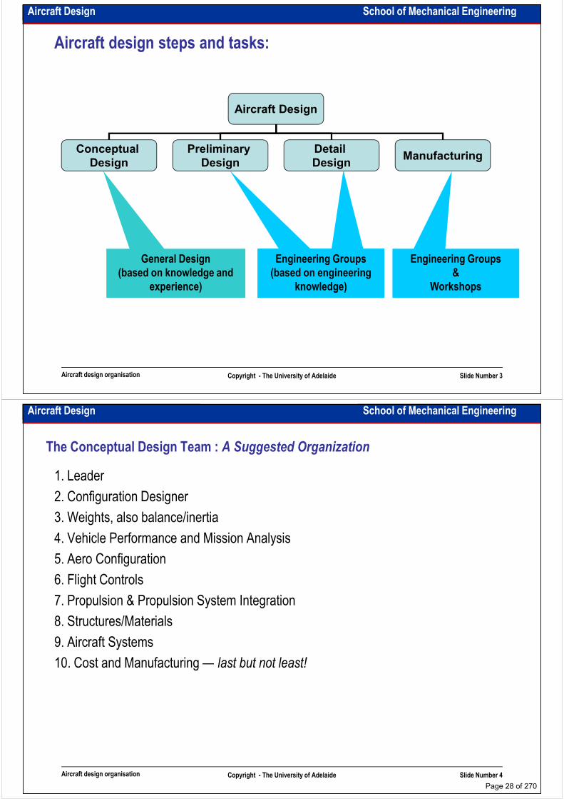
Aircraft design matrix organisation:
You work for a project
You work in an organisational team
Aircraft design organisation Copyright - The University of Adelaide Slide Number 2
From Virginia Tech University by W.H. Mawson
Page 27 of 270
Aircraft Design School of Mechanical Engineering
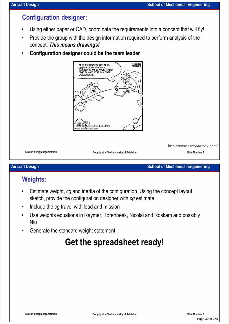
Aircraft design steps and tasks:
Aircraft Design
Conceptual
Design
Preliminary
Design
Detail
DesignManufacturing
General Design Engineering GroupsEngineering Groups Engineering Groups
Aircraft design organisation Copyright - The University of Adelaide Slide Number 3
General Design
(based on knowledge and
experience)
Engineering Groups
(based on engineering
knowledge)
Engineering Groups
(based on engineering
knowledge)
Engineering Groups
&
Workshops
Aircraft Design School of Mechanical Engineering
The Conceptual Design Team : A Suggested Organization
1. Leader
2. Configuration Designer
3. Weights, also balance/inertia
4. Vehicle Performance and Mission Analysis4. Vehicle Performance and Mission Analysis
5. Aero Configuration
6. Flight Controls
7. Propulsion & Propulsion System Integration
8. Structures/Materials
9. Aircraft Systems
10. Cost and Manufacturing — last but not least!
Aircraft design organisation Copyright - The University of Adelaide Slide Number 4
10. Cost and Manufacturing — last but not least!
Page 28 of 270

Aircraft Design School of Mechanical Engineering
Aircraft design groups:
Beauty in the Eye of the Beholder
Aircraft design organisation Copyright - The University of Adelaide Slide Number 5
From book: fundamental of aircraft design by L.M. Nicolai
Aircraft Design School of Mechanical Engineering
Leader:
• Make sure that everything is coordinated, that the person who needs help gets it,
and that communications exist between every team member.
• Set schedules and meet deadlines, working with the configurator and the entire
team, establish the “vision” of the concept.team, establish the “vision” of the concept.
• Work with the group to define the decision making process for each part of the
design process: What do we need to decide, how will we do it?
• Keep the design notebook, recording the project history, data and team member
commitments.
• Lead the design review presentation. Make sure that everyone is working on the
same airplane, and that the presentations and reports are properly coordinated.
Aircraft design organisation Copyright - The University of Adelaide Slide Number 6
Page 29 of 270
Aircraft Design School of Mechanical Engineering
Configuration designer:
• Using either paper or CAD, coordinate the requirements into a concept that will fly!
• Provide the group with the design information required to perform analysis of the
concept. This means drawings!
• Configuration designer could be the team leader• Configuration designer could be the team leader
Aircraft design organisation Copyright - The University of Adelaide Slide Number 7
http://www.cartoonstock.com/
Aircraft Design School of Mechanical Engineering
Weights:
• Estimate weight, cg and inertia of the configuration. Using the concept layout
sketch, provide the configuration designer with cg estimate.
• Include the cg travel with load and mission
• Use weights equations in Raymer, Torenbeek, Nicolai and Roskam and possibly • Use weights equations in Raymer, Torenbeek, Nicolai and Roskam and possibly
Niu
• Generate the standard weight statement.
Get the spreadsheet ready!
Aircraft design organisation Copyright - The University of Adelaide Slide Number 8
Page 30 of 270
Aircraft Design School of Mechanical Engineering
Vehicle Performance and Mission Analysis:
• Develop the mission profile(s). Make sure the airplane can perform the design
mission, and define the fallout capability for other missions. This includes operation
of the sizing code and generation of carpet plots illustrating the basic sizing in terms
of thrust and wing area, and the constraint lines imposed by takeoff, landing,
manoeuvre and acceleration requirements. Compute field performance.manoeuvre and acceleration requirements. Compute field performance.
• Make use of information from the:
– configuration designer regarding geometric definition
– aero person for the aerodynamic characteristics
– propulsion person for the basic “engine deck” data and corrections to account
for installation
– weights person to establish the system weights
Aircraft design organisation Copyright - The University of Adelaide Slide Number 9
– weights person to establish the system weights
• Note: each one of these people should check the output from sizing to make sure
that the data being used is correct.
Aircraft Design School of Mechanical Engineering
Aerodynamic Configuration Design and Analysis:
• Define the “design drivers.” What’s the best configuration to do the required mission
from an aerodynamics point of view? Ensure the concept is aerodynamically
efficient. Think streamlined!
• Provide the neutral point to the configuration designer.• Provide the neutral point to the configuration designer.
• Estimate zero lift drag, including skin friction, wave, form and misc. drag. FRICTION
is available for the skin friction and form drag estimate.
• Estimate the induced drag, establish a target span.
• Select the specific airfoils and design the wing (twist).
• Make the drag polars, and make sure they are trimmed.
• Provide estimates of CLmax (trimmed) for landing and takeoff and define the high
lift concept required to achieve that CLmax
Aircraft design organisation Copyright - The University of Adelaide Slide Number 10
lift concept required to achieve that CLmax
• Work with Stability and Control: Cm0, etc.
Page 31 of 270
Aircraft Design School of Mechanical Engineering
Handling Qualities, Stability, Control, and Flight Controls:
• Develop control power requirements (criteria) for the mission
• Decide how best to meet the requirements,
– stable or unstable?
– canard or aft tail, etc.– canard or aft tail, etc.
• Estimate your design’s control power (be able to trim with adequate control margin
at critical points in flight envelope).
– are the control power requirements defined above met?
– use X-plots to size the tails
• Assess design stability (use DATCOM or JKayvlm & spreadsheet or equivalent.
Note the new Drela VLM). Decide on control system.
Aircraft design organisation Copyright - The University of Adelaide Slide Number 11
Note the new Drela VLM). Decide on control system.
• Meet MIL spec and FAR requirements for flying qualities.
Aircraft Design School of Mechanical Engineering
Intentionally left blank for your notes
………………………………………………………………………………………………
………………………………………………………………………………………………
………………………………………………………………………………………………
………………………………………………………………………………………………………………………………………………………………………………………………
………………………………………………………………………………………………
………………………………………………………………………………………………
………………………………………………………………………………………………
………………………………………………………………………………………………
………………………………………………………………………………………………
………………………………………………………………………………………………
………………………………………………………………………………………………
………………………………………………………………………………………………
………………………………………………………………………………………………
Aircraft design organisation Copyright - The University of Adelaide Slide Number 12
………………………………………………………………………………………………
………………………………………………………………………………………………
………………………………………………………………………………………………
………………………………………………………………………………………………
………………………………………………………………………………………………
………………………………………………………………………………………….
Page 32 of 270
Aircraft Design School of Mechanical Engineering
Propulsion and Propulsion System Integration:
• Select the type of propulsion system appropriate for the specified design
requirements
• provide the Thrust and sfc characteristics for the entire flight envelope for use in the
mission analysismission analysis
• Define the thrust and fuel flow for the engine you selected throughout the flight
envelope
• Supply scaling and weight data to the performance team
• Define the appropriate engine inlet and nozzle, or propeller system for each aircraft
concept the group is investigating.
• Size the inlet capture area or the prop
• Estimate the installation losses.
Aircraft design organisation Copyright - The University of Adelaide Slide Number 13
• Estimate the installation losses.
• With the aero team, define the thrust-drag bookkeeping system.
Aircraft Design School of Mechanical Engineering
Structures/Materials:
• Develop an appropriate materials basis (cost/complexity; example: compare
volumetric efficiency of composites vs. wave drag penalty at supersonic speeds)
• Ensure a structural concept that “supports” the configuration, i.e., identify the load
paths for wing, landing gear, tail, etc.paths for wing, landing gear, tail, etc.
• Define critical loads requirements for defining structural design basis. (Draw a
good V-n diagram)
• See Torenbeek, the other parts of Roskam for structural design guidance, and Niu,
as well as the overview by Raymer.
• Size the members (skin, bulkheads, etc.)
Aircraft design organisation Copyright - The University of Adelaide Slide Number 14
Page 33 of 270

Aircraft Design School of Mechanical Engineering
Aircraft Systems:
• Landing Gear
• Details on systems required in the aircraft
• Crew station requirements, cockpit layout
• Passenger and cargo arrangement (volume and weight)• Passenger and cargo arrangement (volume and weight)
• Weapons system if appropriate
• Avionics systems
• Other mechanical systems (actuators)
• Technology developments and current systems used
• Concentrate on weight, volume and power requirements
Aircraft design organisation Copyright - The University of Adelaide Slide Number 15
Aircraft Design School of Mechanical Engineering
Cost and Manufacturing
• No decision made without cost consideration
• Design decisions must be manufacturable
• Manufacturing cost should be considered
• Modular production techniques could be used• Modular production techniques could be used
• If it is cheaper it doesn't mean that it is better & If it is more expensive it doesn't
mean that it is better!
• Good engineers must be able to sell his/her idea on the best price
Aircraft design organisation Copyright - The University of Adelaide Slide Number 16
Page 34 of 270
Aircraft Design School of Mechanical Engineering
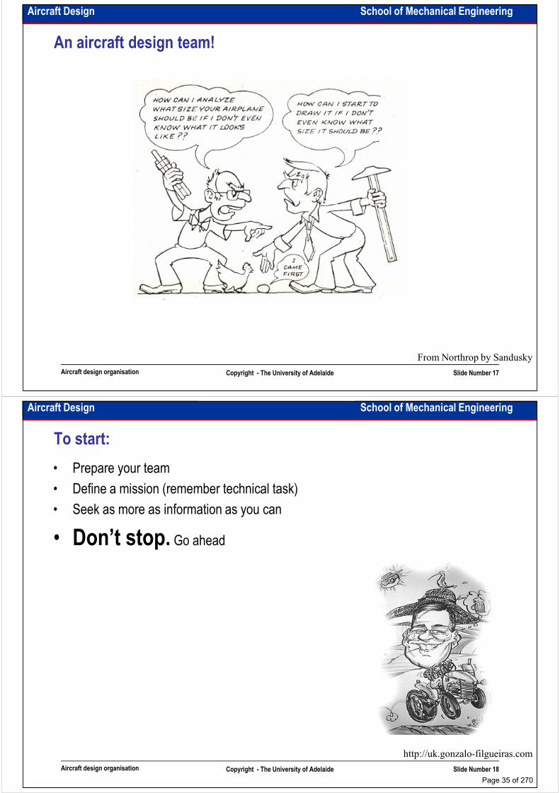
An aircraft design team!
Aircraft design organisation Copyright - The University of Adelaide Slide Number 17
From Northrop by Sandusky
Aircraft Design School of Mechanical Engineering
To start:
• Prepare your team
• Define a mission (remember technical task)
• Seek as more as information as you can
• Don’t stop.• Don’t stop. Go ahead
Aircraft design organisation Copyright - The University of Adelaide Slide Number 18
http://uk.gonzalo-filgueiras.com
Page 35 of 270
Aircraft Design School of Mechanical Engineering
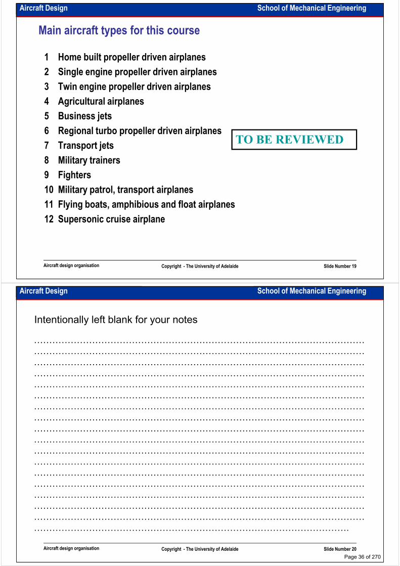
Main aircraft types for this course
1 Home built propeller driven airplanes
2 Single engine propeller driven airplanes
3 Twin engine propeller driven airplanes
4 Agricultural airplanes4 Agricultural airplanes
5 Business jets
6 Regional turbo propeller driven airplanes
7 Transport jets
8 Military trainers
9 Fighters
10 Military patrol, transport airplanes
TO BE REVIEWED
Aircraft design organisation Copyright - The University of Adelaide Slide Number 19
10 Military patrol, transport airplanes
11 Flying boats, amphibious and float airplanes
12 Supersonic cruise airplane
Aircraft Design School of Mechanical Engineering
Intentionally left blank for your notes
………………………………………………………………………………………………
………………………………………………………………………………………………
………………………………………………………………………………………………
………………………………………………………………………………………………………………………………………………………………………………………………
………………………………………………………………………………………………
………………………………………………………………………………………………
………………………………………………………………………………………………
………………………………………………………………………………………………
………………………………………………………………………………………………
………………………………………………………………………………………………
………………………………………………………………………………………………
………………………………………………………………………………………………
………………………………………………………………………………………………
Aircraft design organisation Copyright - The University of Adelaide Slide Number 20
………………………………………………………………………………………………
………………………………………………………………………………………………
………………………………………………………………………………………………
………………………………………………………………………………………………
………………………………………………………………………………………………
………………………………………………………………………………………….
Page 36 of 270
School of Mechanical EngineeringAircraft Design
Aircraft weight calculation
Dr. MAZIAR ARJOMANDI
Semester I
Aircraft weight calculation Copyright - The University of Adelaide Slide Number 1
Semester I
Aircraft Design School of Mechanical Engineering
• WTO=W0=design takeoff gross weight (total weight of the aircraft as it begins the mission
which the aircraft is designed for).
W0 could be less than Wmax (e.g. in military aircraft)
Takeoff weight build-up:
• Wf=mission fuel weight
Wf is not considered trapped fuel weight
• We=empty weight (includes the structure, engines, landing gear, fixed equipment, avionics,
and anything else not considered a part of crew, payload, or fuel)
• Woe=operational empty weight (includes: empty weight, trapped fuel weight, crew weight)
Aircraft weight calculation Copyright - The University of Adelaide Slide Number 2
Page 37 of 270

Aircraft Design School of Mechanical Engineering
Takeoff weight build-up:
ef
payloadcrew
emptyfuelpayloadcrew
WW
WW
W
WWWW
WWWWW
+
++=
+++=
0
0
0
0
0
0
:hence known, are weightspayload and crew The
ef
payloadcrew
ef
payloadcrew
payloadcrewef
WW
WWW
W
W
W
W
WWW
WWWW
WW
W
WW
WW
−−
+=
−
−
+=∴
+=
−
−∴
1,
1
0
00
0
0
0
0
0
0
00
or
The general
equation for
calculating
aircraft weight
n
Aircraft weight calculation Copyright - The University of Adelaide Slide Number 3
∑
∑
=
=
−
=m
nj
unknown
n
i
known
W
W
W
1
10
• It means that we use weight fraction for
the components with unknown weight
parameters. For example, if we use built
engines, engines’ weights are known.
Aircraft Design School of Mechanical Engineering
Intentionally left blank for your notes
………………………………………………………………………………………………
………………………………………………………………………………………………
………………………………………………………………………………………………
………………………………………………………………………………………………………………………………………………………………………………………………
………………………………………………………………………………………………
………………………………………………………………………………………………
………………………………………………………………………………………………
………………………………………………………………………………………………
………………………………………………………………………………………………
………………………………………………………………………………………………
………………………………………………………………………………………………
………………………………………………………………………………………………
………………………………………………………………………………………………
Aircraft weight calculation Copyright - The University of Adelaide Slide Number 4
………………………………………………………………………………………………
………………………………………………………………………………………………
………………………………………………………………………………………………
………………………………………………………………………………………………
………………………………………………………………………………………………
………………………………………………………………………………………….
Page 38 of 270
Aircraft Design School of Mechanical Engineering
How could we calculate crew weight?
• If it is not given by customer, use standards
• Crew weight is usually 85kg
• Add to this number at least 15kg for baggage (in special aircraft it could be up to 50kg)
• Consider aircraft type (e.g. in human powered aircraft we try to hire a thin but strong pilot)• Consider aircraft type (e.g. in human powered aircraft we try to hire a thin but strong pilot)
• If it is a passenger aircraft crew is pilots, flight engineers, and stewardesses
• If it is UAV, Wcrew=0
How could we calculate payload weight?• For passenger/civil aircraft:
– It is given by customer
– Don’t forget baggage
• For fighter/military aircraft:
Aircraft weight calculation Copyright - The University of Adelaide Slide Number 5
• For fighter/military aircraft:
– It should be calculated according to the mission (it is usually done by Air Force
engineers; probability analysis, game theory, scenario imagination, world
geopolitical situation and …)
– Droppable payload is payload (cargo, bomb, parachutist, pesticides, …)
• Usual UAVs have no payload (except UCAVs). Cameras on UAVs are not payload!
Aircraft Design School of Mechanical Engineering
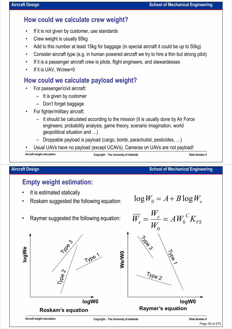
Empty weight estimation:
eWBAW loglog 0 +=
VS
Cee KAWW
W 0==
• It is estimated statically
• Roskam suggested the following equation:
• Raymer suggested the following equation:
logWe
We/W
0
VSe KAWW
W 0
0
==• Raymer suggested the following equation:
Aircraft weight calculation Copyright - The University of Adelaide Slide Number 6
Roskam’s equation Raymer’s equation
logW0 logW0
Page 39 of 270

Aircraft Design School of Mechanical Engineering
Roskam’s equation
eWBAW loglog 0 +=
Aircraft weight calculation Copyright - The University of Adelaide Slide Number 7
From Book: Aeroplane design by J. Roskam
Aircraft Design School of Mechanical Engineering
Intentionally left blank for your notes
………………………………………………………………………………………………
………………………………………………………………………………………………
………………………………………………………………………………………………
………………………………………………………………………………………………………………………………………………………………………………………………
………………………………………………………………………………………………
………………………………………………………………………………………………
………………………………………………………………………………………………
………………………………………………………………………………………………
………………………………………………………………………………………………
………………………………………………………………………………………………
………………………………………………………………………………………………
………………………………………………………………………………………………
………………………………………………………………………………………………
Aircraft weight calculation Copyright - The University of Adelaide Slide Number 8
………………………………………………………………………………………………
………………………………………………………………………………………………
………………………………………………………………………………………………
………………………………………………………………………………………………
………………………………………………………………………………………………
………………………………………………………………………………………….
Page 40 of 270

Aircraft Design School of Mechanical Engineering
Raymer’s equation
VS
C
e KAWW 0=
Aircraft Type A C
Sailplane – unpowered 0.86 -0.05 Sailplane – powered 0.91 -0.05 Sailplane – powered 0.91 -0.05 Homebuilt – metal/wood 1.19 0.09 Homebuilt – composite 0.99 -0.09 General aviation – single engine 2.36 -0.18 General aviation – twin engine 1.51 -0.10 Agricultural aircraft 0.74 -0.03 Twin turboprop 0.96 -0.05 Flying boat 1.09 -0.05 Jet trainer 1.59 -0.10 Jet fighter 2.34 -0.13
Aircraft weight calculation Copyright - The University of Adelaide Slide Number 9
From Book: Aircraft design; a conceptual approach, by D. Raymer
Jet fighter 2.34 -0.13 Military cargo/bomber 0.93 -0.07 Jet transport 1.02 -0.06
sweep variableif 04.1
sweep fixed if 00.1
=
=
VS
VS
K
K
Aircraft Design School of Mechanical Engineering
An example: high altitude UAV
Aircraft weight calculation Copyright - The University of Adelaide Slide Number 10
Page 41 of 270
Aircraft Design School of Mechanical Engineering
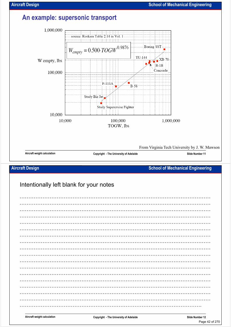
An example: supersonic transport
Aircraft weight calculation Copyright - The University of Adelaide Slide Number 11
From Virginia Tech University by J. W. Mawson
Aircraft Design School of Mechanical Engineering
Intentionally left blank for your notes
………………………………………………………………………………………………
………………………………………………………………………………………………
………………………………………………………………………………………………
………………………………………………………………………………………………………………………………………………………………………………………………
………………………………………………………………………………………………
………………………………………………………………………………………………
………………………………………………………………………………………………
………………………………………………………………………………………………
………………………………………………………………………………………………
………………………………………………………………………………………………
………………………………………………………………………………………………
………………………………………………………………………………………………
………………………………………………………………………………………………
Aircraft weight calculation Copyright - The University of Adelaide Slide Number 12
………………………………………………………………………………………………
………………………………………………………………………………………………
………………………………………………………………………………………………
………………………………………………………………………………………………
………………………………………………………………………………………………
………………………………………………………………………………………….
Page 42 of 270

Aircraft Design School of Mechanical Engineering
Empty weight fraction consideration:
• Both methods give approximately similar answers
• Both methods recommend to use correction coefficients for composite aircraft
• The graph of We vs. W0 is named “technology diagram” as it shows the amount of
takeoff which could be carried by 1kg of empty weight.
Your duty:
Tables could be used only for solving course
assignments and examination questions. In real design
takeoff which could be carried by 1kg of empty weight.
• The coefficients provided for both methods in the books are for the Imperial Units.
Aircraft weight calculation Copyright - The University of Adelaide Slide Number 13
assignments and examination questions. In real design
and design project you have to derive the equations
and calculate the coefficients
Aircraft Design School of Mechanical Engineering
Intentionally left blank for your notes
………………………………………………………………………………………………
………………………………………………………………………………………………
………………………………………………………………………………………………
………………………………………………………………………………………………………………………………………………………………………………………………
………………………………………………………………………………………………
………………………………………………………………………………………………
………………………………………………………………………………………………
………………………………………………………………………………………………
………………………………………………………………………………………………
………………………………………………………………………………………………
………………………………………………………………………………………………
………………………………………………………………………………………………
………………………………………………………………………………………………
Aircraft weight calculation Copyright - The University of Adelaide Slide Number 14
………………………………………………………………………………………………
………………………………………………………………………………………………
………………………………………………………………………………………………
………………………………………………………………………………………………
………………………………………………………………………………………………
………………………………………………………………………………………….
Page 43 of 270
School of Mechanical EngineeringAircraft Design
Mission fuel weight
Dr. MAZIAR ARJOMANDI
Semester I
Mission fuel weight Copyright - The University of Adelaide Slide Number 1
Semester I
Aircraft Design School of Mechanical Engineering
Mission profile:
• It is usually given by the customer
• If you want to work it out, you have to simulate your aircraft and flight environment
• This is a multidisciplinary optimisation problem
• If it is a civil aircraft it will be done by airlines or related institutions; If it is a military aircraft it
will be done by army specialists
• They usually use effectiveness calculation method, probability analysis and game theory
approaches.
• In this course we use general mission profiles related to the aircraft type
Mission fuel weight Copyright - The University of Adelaide Slide Number 2
Page 44 of 270
Aircraft Design School of Mechanical Engineering
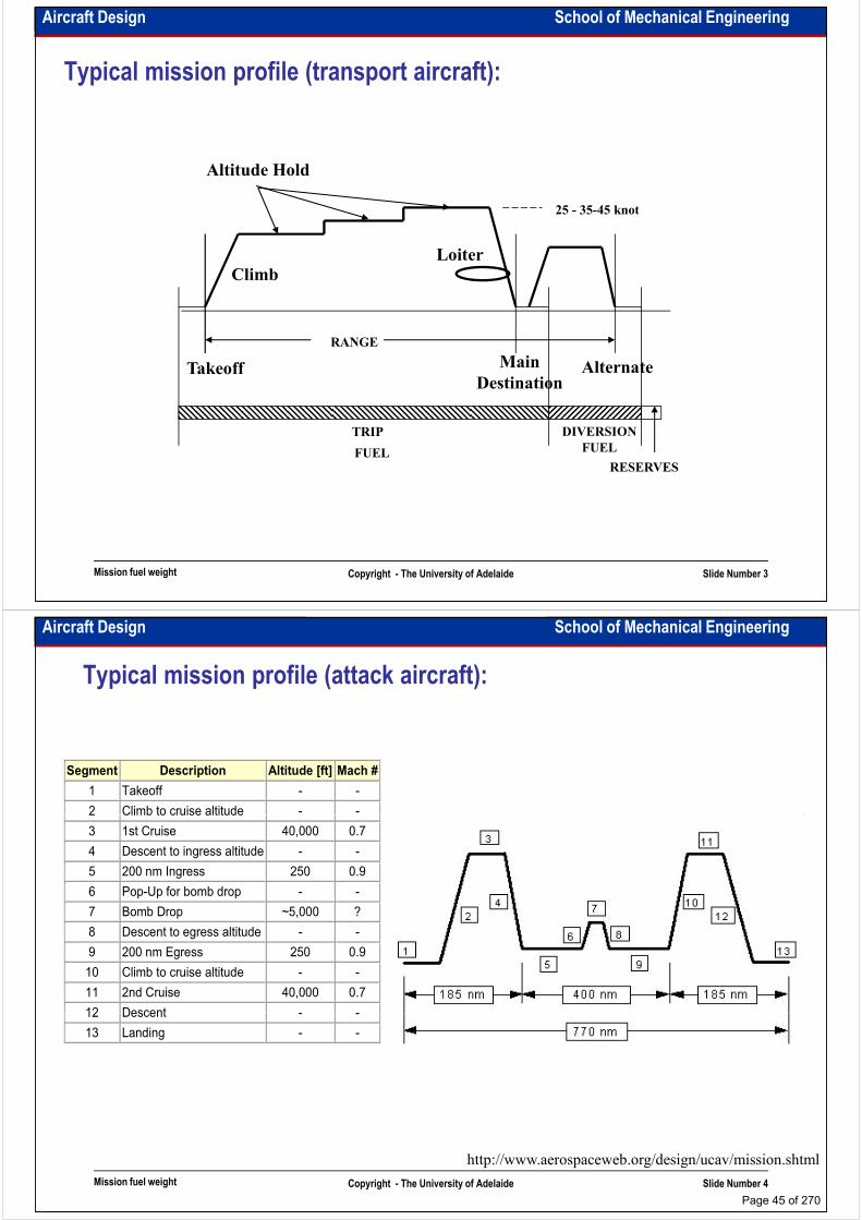
Typical mission profile (transport aircraft):
Altitude Hold
25 - 35-45 knot
RANGE
Climb
25 - 35-45 knot
Loiter
Main
Destination
AlternateTakeoff
Mission fuel weight Copyright - The University of Adelaide Slide Number 3
TRIP
FUEL
DIVERSION
FUEL
RESERVES
Aircraft Design School of Mechanical Engineering
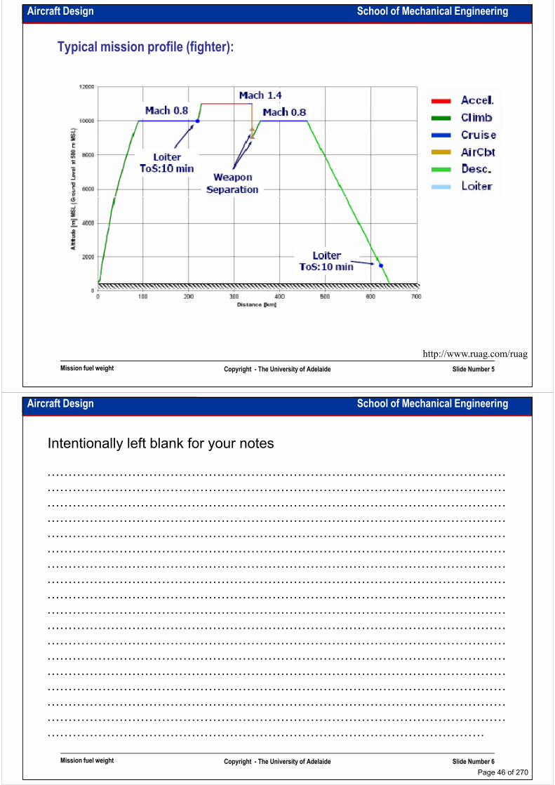
Typical mission profile (attack aircraft):
Segment Description Altitude [ft] Mach #
1 Takeoff - -
2 Climb to cruise altitude - - 2 Climb to cruise altitude - -
3 1st Cruise 40,000 0.7
4 Descent to ingress altitude - -
5 200 nm Ingress 250 0.9
6 Pop-Up for bomb drop - -
7 Bomb Drop ~5,000 ?
8 Descent to egress altitude - -
9 200 nm Egress 250 0.9
10 Climb to cruise altitude - -
11 2nd Cruise 40,000 0.7
12 Descent - -
Mission fuel weight Copyright - The University of Adelaide Slide Number 4
12 Descent - -
13 Landing - -
http://www.aerospaceweb.org/design/ucav/mission.shtml
Page 45 of 270
Aircraft Design School of Mechanical Engineering
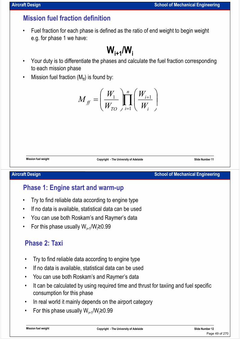
Typical mission profile (fighter):
Mission fuel weight Copyright - The University of Adelaide Slide Number 5
http://www.ruag.com/ruag
Aircraft Design School of Mechanical Engineering
Intentionally left blank for your notes
………………………………………………………………………………………………
………………………………………………………………………………………………
………………………………………………………………………………………………
………………………………………………………………………………………………………………………………………………………………………………………………
………………………………………………………………………………………………
………………………………………………………………………………………………
………………………………………………………………………………………………
………………………………………………………………………………………………
………………………………………………………………………………………………
………………………………………………………………………………………………
………………………………………………………………………………………………
………………………………………………………………………………………………
………………………………………………………………………………………………
Mission fuel weight Copyright - The University of Adelaide Slide Number 6
………………………………………………………………………………………………
………………………………………………………………………………………………
………………………………………………………………………………………………
………………………………………………………………………………………………
………………………………………………………………………………………………
………………………………………………………………………………………….
Page 46 of 270

Aircraft Design School of Mechanical Engineering
Typical mission profile (atmosphere research):
Mission fuel weight Copyright - The University of Adelaide Slide Number 7
http://www.grida.no/climate/ipcc/aviation/avf9-6.htm
Aircraft Design School of Mechanical Engineering
Typical mission profile (reconnaissance aircraft) - SR71:
Mission fuel weight Copyright - The University of Adelaide Slide Number 8
http://www.blackbirds.net/sr71/srmissionp.html
Page 47 of 270

Aircraft Design School of Mechanical Engineering
Typical mission profile (reconnaissance UAV) – Global Hawk:
Mission fuel weight Copyright - The University of Adelaide Slide Number 9
http://www.emporia.edu/earthsci/student/graves1/project.html
Aircraft Design School of Mechanical Engineering
Typical mission profile (jet trainer) – Yak-130:
Mission fuel weight Copyright - The University of Adelaide Slide Number 10
http://www.yak.ru
Page 48 of 270
Aircraft Design School of Mechanical Engineering
Mission fuel fraction definition
• Fuel fraction for each phase is defined as the ratio of end weight to begin weight
e.g. for phase 1 we have:
Wi+1/Wii+1 i• Your duty is to differentiate the phases and calculate the fuel fraction corresponding
to each mission phase
• Mission fuel fraction (Mff) is found by:
∏=
+
=
n
i i
i
TO
ffW
W
W
WM
1
11
Mission fuel weight Copyright - The University of Adelaide Slide Number 11
Aircraft Design School of Mechanical Engineering
Phase 1: Engine start and warm-up
• Try to find reliable data according to engine type
• If no data is available, statistical data can be used
• You can use both Roskam’s and Raymer’s data
• For this phase usually Wi+1/Wi≥0.99• For this phase usually Wi+1/Wi≥0.99
Phase 2: Taxi
• Try to find reliable data according to engine type
• If no data is available, statistical data can be used
• You can use both Roskam’s and Raymer’s data
Mission fuel weight Copyright - The University of Adelaide Slide Number 12
• It can be calculated by using required time and thrust for taxiing and fuel specific
consumption for this phase
• In real world it mainly depends on the airport category
• For this phase usually Wi+1/Wi≥0.99
Page 49 of 270

Aircraft Design School of Mechanical Engineering
Phase 3: Takeoff
• Try to find reliable data according to engine type
• If no data is available, statistical data can be used
• You can use both Roskam’s and Raymer’s data
• It can be calculated by using required time and thrust for takeoff and fuel specific • It can be calculated by using required time and thrust for takeoff and fuel specific
consumption for this phase
• In real world it mainly depends on the airport category
• For this phase usually Wi+1/Wi≥0.99
Mission fuel weight Copyright - The University of Adelaide Slide Number 13
Aircraft Design School of Mechanical Engineering
• Try to find reliable data according to engine type
• If no data is available, statistical data can be used
• You can use both Roskam’s and Raymer’s data
• It can be calculated by using required time and thrust for climb and fuel
Phase 4: Climb
• It can be calculated by using required time and thrust for climb and fuel
specific consumption for this phase. Breguet’s loiter equation is used to find
time to climb
=
=
−
−
i
i
clclj
jet
cl
i
i
clclp
p
cl
propeller
cl
W
W
D
L
Ct
W
W
D
L
CVt
1
1
ln1
ln1 η
Mission fuel weight Copyright - The University of Adelaide Slide Number 14
• It mainly depends on the climb altitude and cruise speed
• For this phase usually Wi+1/Wi≥0.98
Page 50 of 270
Aircraft Design School of Mechanical Engineering
Intentionally left blank for your notes
………………………………………………………………………………………………
………………………………………………………………………………………………
………………………………………………………………………………………………
………………………………………………………………………………………………………………………………………………………………………………………………
………………………………………………………………………………………………
………………………………………………………………………………………………
………………………………………………………………………………………………
………………………………………………………………………………………………
………………………………………………………………………………………………
………………………………………………………………………………………………
………………………………………………………………………………………………
………………………………………………………………………………………………
………………………………………………………………………………………………
Mission fuel weight Copyright - The University of Adelaide Slide Number 15
………………………………………………………………………………………………
………………………………………………………………………………………………
………………………………………………………………………………………………
………………………………………………………………………………………………
………………………………………………………………………………………………
………………………………………………………………………………………….
Aircraft Design School of Mechanical Engineering
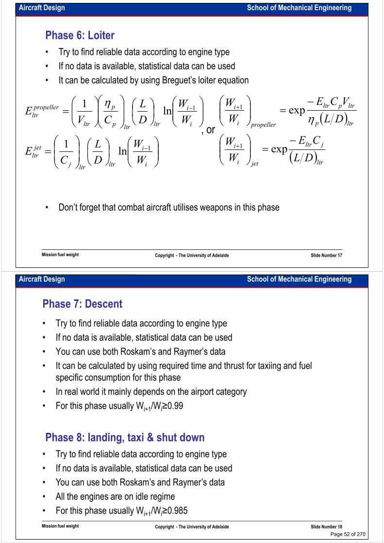
• Try to find reliable data according to engine type
• If no data is available, statistical data can be used
• It can be calculated by using Breguet’s range equation
Phase 5: Cruise
=
=
−
−
i
i
crcrj
jet
cr
i
i
crcrp
ppropeller
cr
W
W
D
L
C
VR
W
W
D
L
CR
1
1
ln
lnη
( )
( )cr
jcr
jeti
i
crp
pcr
propelleri
i
DLV
CR
W
W
DL
CR
W
W
−=
−=
+
+
exp
exp
1
1
η, or
Mission fuel weight Copyright - The University of Adelaide Slide Number 16
• Don’t forget that combat aircraft utilises weapons in this phase
Page 51 of 270
Aircraft Design School of Mechanical Engineering
• Try to find reliable data according to engine type
• If no data is available, statistical data can be used
• It can be calculated by using Breguet’s loiter equation
Phase 6: Loiter
=
=
−
−
i
i
ltrltrj
jet
ltr
i
i
ltrltrp
p
ltr
propeller
ltr
W
W
D
L
CE
W
W
D
L
CVE
1
1
ln1
ln1 η
( )
( )ltr
jltr
jeti
i
ltrp
ltrpltr
propelleri
i
DL
CE
W
W
DL
VCE
W
W
−=
−=
+
+
exp
exp
1
1
η, or
Mission fuel weight Copyright - The University of Adelaide Slide Number 17
• Don’t forget that combat aircraft utilises weapons in this phase
Aircraft Design School of Mechanical Engineering
• Try to find reliable data according to engine type
• If no data is available, statistical data can be used
• You can use both Roskam’s and Raymer’s data
• It can be calculated by using required time and thrust for taxiing and fuel
Phase 7: Descent
• It can be calculated by using required time and thrust for taxiing and fuel
specific consumption for this phase
• In real world it mainly depends on the airport category
• For this phase usually Wi+1/Wi≥0.99
• Try to find reliable data according to engine type
Phase 8: landing, taxi & shut down
Mission fuel weight Copyright - The University of Adelaide Slide Number 18
• Try to find reliable data according to engine type
• If no data is available, statistical data can be used
• You can use both Roskam’s and Raymer’s data
• All the engines are on idle regime
• For this phase usually Wi+1/Wi≥0.985
Page 52 of 270

Aircraft Design School of Mechanical Engineering
Phase 9: Combat operation
• We need to know the number of turns and load factor for specific operation to
calculate combat fuel fraction
Combat fuel = sfc×thrust×time
• Turn rate can be calculated by:
• Time for operation = (no of turns)(360°)/(turn rate)
V
ng 12 −=ψɺ rate Turn
Mission fuel weight Copyright - The University of Adelaide Slide Number 19
Aircraft Design School of Mechanical Engineering
Where to get data to put in formulae?
• Use engines data for engine specification and SFC
• Use historical data for L/D or use wetted aspect ratio
– Historical data can be found by statistical analysis
– Wetted aspect ratio = b2/Swet = A/(Swet/Sref), Swet/Sref is the relationship between – Wetted aspect ratio = b2/Swet = A/(Swet/Sref), Swet/Sref is the relationship between
wetted area and reference area
– Use next slide to estimate L/D
To find wetted area you have to sketch the aircraft• Unknown data could be estimated by using statistics
Mission fuel weight Copyright - The University of Adelaide Slide Number 20
Page 53 of 270

Aircraft Design School of Mechanical Engineering
L/D estimation:
Mission fuel weight Copyright - The University of Adelaide Slide Number 21
From Book: Aircraft design; a conceptual approach, by D. Raymer
Aircraft Design School of Mechanical Engineering
A classic example for
understanding L/D: B-47 vs
Avro Vulcan B-1:
• traditional idea: higher AR gives
higher L/D
• low AR wing with less wetted area
competes with high AR
Mission fuel weight Copyright - The University of Adelaide Slide Number 22
From Book: Aircraft design; a conceptual
approach, by D. Raymer
Page 54 of 270
Aircraft Design School of Mechanical Engineering
Intentionally left blank for your notes
………………………………………………………………………………………………
………………………………………………………………………………………………
………………………………………………………………………………………………
………………………………………………………………………………………………………………………………………………………………………………………………
………………………………………………………………………………………………
………………………………………………………………………………………………
………………………………………………………………………………………………
………………………………………………………………………………………………
………………………………………………………………………………………………
………………………………………………………………………………………………
………………………………………………………………………………………………
………………………………………………………………………………………………
………………………………………………………………………………………………
Mission fuel weight Copyright - The University of Adelaide Slide Number 23
………………………………………………………………………………………………
………………………………………………………………………………………………
………………………………………………………………………………………………
………………………………………………………………………………………………
………………………………………………………………………………………………
………………………………………………………………………………………….
Aircraft Design School of Mechanical Engineering
Span trap
Mission fuel weight Copyright - The University of Adelaide Slide Number 24
Span plays a bigger role than aspect ratio!
Page 55 of 270
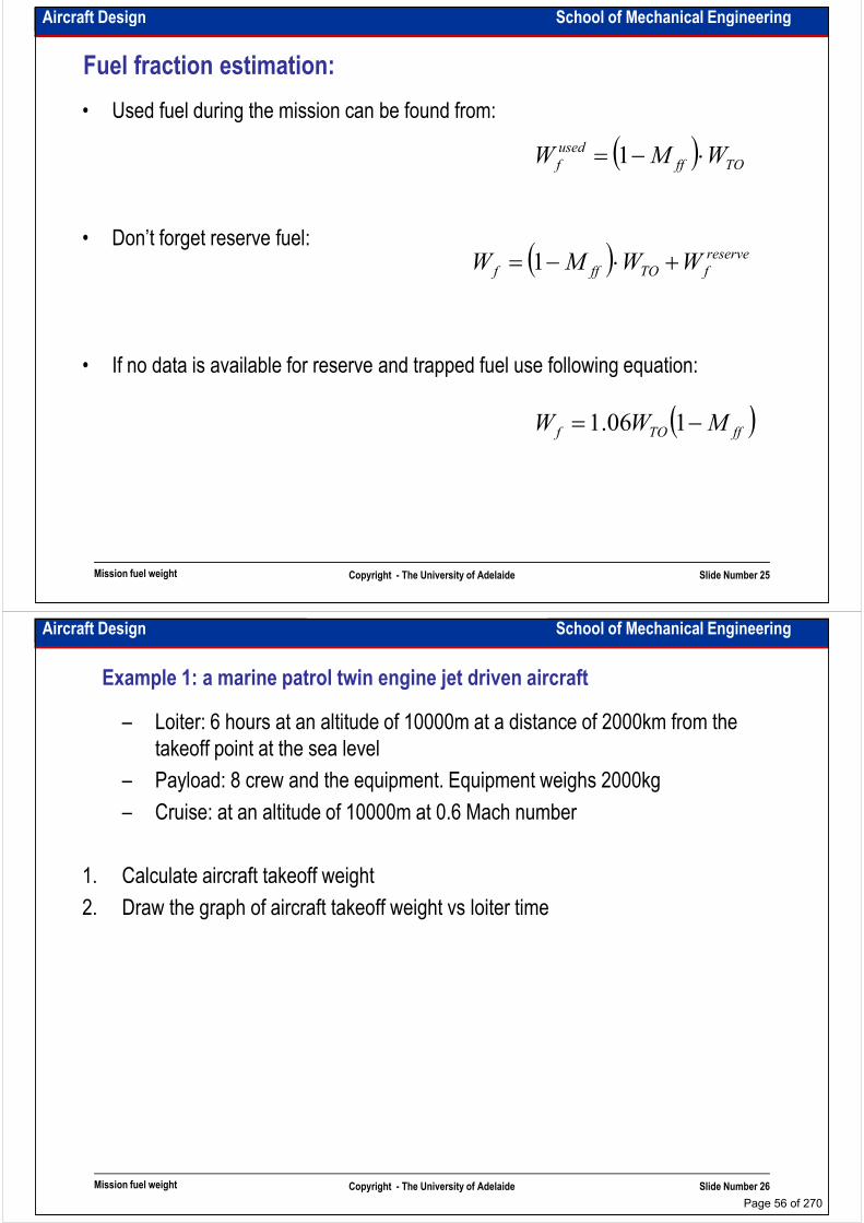
Aircraft Design School of Mechanical Engineering
Fuel fraction estimation:
• Used fuel during the mission can be found from:
( )TOff
used
f WMW ⋅−= 1
• Don’t forget reserve fuel:
• If no data is available for reserve and trapped fuel use following equation:
( ) reserve
fTOfff WWMW +⋅−= 1
Mission fuel weight Copyright - The University of Adelaide Slide Number 25
( )ffTOf MWW −= 106.1
Aircraft Design School of Mechanical Engineering
Example 1: a marine patrol twin engine jet driven aircraft
– Loiter: 6 hours at an altitude of 10000m at a distance of 2000km from the
takeoff point at the sea level
– Payload: 8 crew and the equipment. Equipment weighs 2000kg
– Cruise: at an altitude of 10000m at 0.6 Mach number– Cruise: at an altitude of 10000m at 0.6 Mach number
1. Calculate aircraft takeoff weight
2. Draw the graph of aircraft takeoff weight vs loiter time
Mission fuel weight Copyright - The University of Adelaide Slide Number 26
Page 56 of 270

Aircraft Design School of Mechanical Engineering
Intentionally left blank for your notes
………………………………………………………………………………………………
………………………………………………………………………………………………
………………………………………………………………………………………………
………………………………………………………………………………………………………………………………………………………………………………………………
………………………………………………………………………………………………
………………………………………………………………………………………………
………………………………………………………………………………………………
………………………………………………………………………………………………
………………………………………………………………………………………………
………………………………………………………………………………………………
………………………………………………………………………………………………
………………………………………………………………………………………………
………………………………………………………………………………………………
Mission fuel weight Copyright - The University of Adelaide Slide Number 27
………………………………………………………………………………………………
………………………………………………………………………………………………
………………………………………………………………………………………………
………………………………………………………………………………………………
………………………………………………………………………………………………
………………………………………………………………………………………….
Aircraft Design School of Mechanical Engineering
Intentionally left blank for your notes
………………………………………………………………………………………………
………………………………………………………………………………………………
………………………………………………………………………………………………
………………………………………………………………………………………………………………………………………………………………………………………………
………………………………………………………………………………………………
………………………………………………………………………………………………
………………………………………………………………………………………………
………………………………………………………………………………………………
………………………………………………………………………………………………
………………………………………………………………………………………………
………………………………………………………………………………………………
………………………………………………………………………………………………
………………………………………………………………………………………………
Mission fuel weight Copyright - The University of Adelaide Slide Number 28
………………………………………………………………………………………………
………………………………………………………………………………………………
………………………………………………………………………………………………
………………………………………………………………………………………………
………………………………………………………………………………………………
………………………………………………………………………………………….
Page 57 of 270

School of Mechanical EngineeringAircraft Design
Sensitivity analysis
Dr. MAZIAR ARJOMANDI
Semester I
Sensitivity analysis Copyright - The University of Adelaide Slide Number 1
Semester I
Aircraft Design School of Mechanical Engineering
Why do we need to do sensitivity studies?
• To evaluate and refine the design requirements with the customers
• To find out which parameters drive the design
• To determine which areas of technological change must be pursued
• To estimate the impact of optimistic and pessimistic selection of the input • To estimate the impact of optimistic and pessimistic selection of the input
parameters
• To predict further development of the design
We have already done it using trade studies. Here we want to derive the equations
Sensitivity analysis Copyright - The University of Adelaide Slide Number 2
Page 58 of 270

Aircraft Design School of Mechanical Engineering
Takeoff weight sensitivities:
( )
( )reserve
FreserveTOffFuseable
FunuseablecrewPLFuseableTOE
M
WWMW
WWWWWW
=
+⋅−=
−−−−=
1
: have wefraction, fuel reserve use weIf
:have weAlso
:is equationht Empty weig
( )( )( )
( ) ( )( ) ( )crewPLFunuseableffreserveTOE
TOFunuseableFunuseable
TOffreserveFuseable
TOffreserveFreserve
DCWW
WWMMMWW
WMW
WMMW
WMMW
−=
+−−−⋅+−=
⋅=
⋅−+=
⋅−=
111
11
1
:Or
:have weequation main the in equationslast two Replacing
: have weAlso
: have weequations,last two Using
Sensitivity analysis Copyright - The University of Adelaide Slide Number 3
( ) ( )crewPL
Funuseableffreserve
TOE
WWD
MMMC
DCWW
+=
−−⋅+−=
−=
111
:Where
:Or
Aircraft Design School of Mechanical Engineering
Intentionally left blank for your notes
………………………………………………………………………………………………
………………………………………………………………………………………………
………………………………………………………………………………………………
………………………………………………………………………………………………………………………………………………………………………………………………
………………………………………………………………………………………………
………………………………………………………………………………………………
………………………………………………………………………………………………
………………………………………………………………………………………………
………………………………………………………………………………………………
………………………………………………………………………………………………
………………………………………………………………………………………………
………………………………………………………………………………………………
………………………………………………………………………………………………
Sensitivity analysis Copyright - The University of Adelaide Slide Number 4
………………………………………………………………………………………………
………………………………………………………………………………………………
………………………………………………………………………………………………
………………………………………………………………………………………………
………………………………………………………………………………………………
………………………………………………………………………………………….
Page 59 of 270

Aircraft Design School of Mechanical Engineering
Takeoff weight sensitivities:
( )
( ) ( )( )∂∂
−+=−=
+=
DCWBAWDCWW
WBAW
TOTOTOE
ETO
:y parameter desired to W of sesitivity the obtain can weationdifferenti partial Using
:have wethen :replace weIf
:equation this Remember
TO
log
loglog
( ) ( )( )
( )
∂∂
∂∂
−∂∂⋅+⋅
∂∂
−+−⋅
∂∂
+∂∂
=∂∂⋅
−+∂∂
=∂∂
BA
y
D
y
WCW
y
C
DCW
BDCW
y
B
y
A
y
W
W
DCWBAy
Wy
TOTO
TO
TOTO
TO
TOTO
:then
type,aircraft only withvary B and A and linear is W and W between iprelationsh the Since ETO
log1
loglog
Sensitivity analysis Copyright - The University of Adelaide Slide Number 5
∂∂
−∂∂⋅+⋅
∂∂
−⋅
=∂∂
=∂∂
=∂∂
y
D
y
WCW
y
C
DCW
WB
y
W
y
B
y
A
TOTO
TO
TOTO
:have will wethen and 00
Aircraft Design School of Mechanical Engineering
Takeoff weight sensitivities:
:have weequation thesimplify weIf
∂∂
−∂∂
−=
−−
∂∂
y
DBW
y
CBW
DCWDCW
CBW
y
WTOTO
TOTO
TOTO 211
:Or
TOTO
( ) DWBC
y
DBW
y
CBW
y
WTOTO
TO
−⋅−∂∂
−∂∂
=∂∂
1
2
Sensitivity analysis Copyright - The University of Adelaide Slide Number 6
( ) DWBCy TO −⋅−=
∂ 1
Page 60 of 270
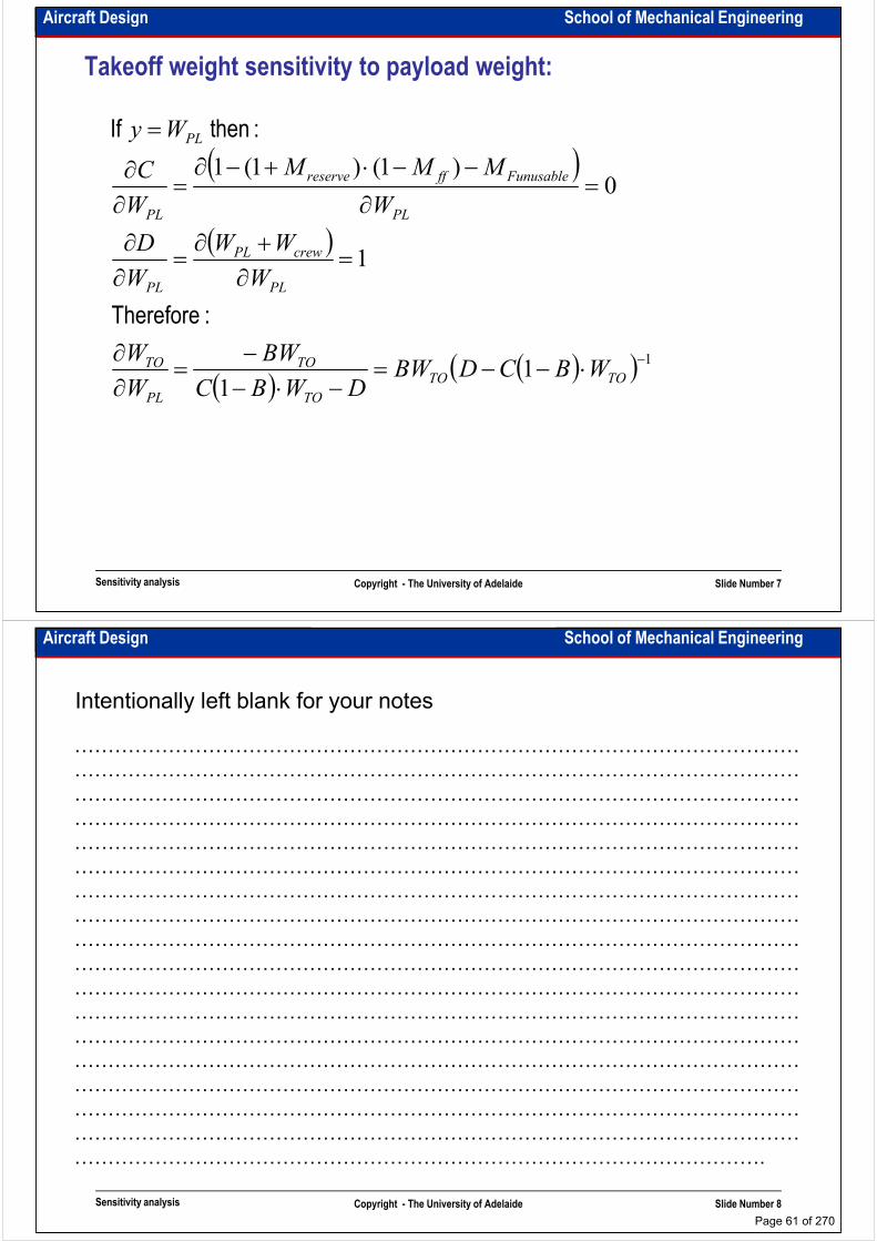
Aircraft Design School of Mechanical Engineering
Takeoff weight sensitivity to payload weight:
( )0
)1()1(1=
∂
−−⋅+−∂=
∂∂
=
PL
Funusableffreserve
PL
PL
W
MMM
W
C
Wy :then If
( )
( )( )( ) 11
1
1
−⋅−−=−⋅−
−=
∂∂
=∂+∂
=∂∂
∂∂
TOTO
TO
TO
PL
TO
PL
crewPL
PL
PLPL
WBCDBWDWBC
BW
W
W
W
WW
W
D
WW
:Therefore
Sensitivity analysis Copyright - The University of Adelaide Slide Number 7
Aircraft Design School of Mechanical Engineering
Intentionally left blank for your notes
………………………………………………………………………………………………
………………………………………………………………………………………………
………………………………………………………………………………………………
………………………………………………………………………………………………………………………………………………………………………………………………
………………………………………………………………………………………………
………………………………………………………………………………………………
………………………………………………………………………………………………
………………………………………………………………………………………………
………………………………………………………………………………………………
………………………………………………………………………………………………
………………………………………………………………………………………………
………………………………………………………………………………………………
………………………………………………………………………………………………
Sensitivity analysis Copyright - The University of Adelaide Slide Number 8
………………………………………………………………………………………………
………………………………………………………………………………………………
………………………………………………………………………………………………
………………………………………………………………………………………………
………………………………………………………………………………………………
………………………………………………………………………………………….
Page 61 of 270
Aircraft Design School of Mechanical Engineering
Example:
• Calculate the sensitivity of takeoff weight to payload weight for the aircraft, given in
the example 1 (marine patrol twin engine jet driven aircraft).
Sensitivity analysis Copyright - The University of Adelaide Slide Number 9
Aircraft Design School of Mechanical Engineering
Intentionally left blank for your notes
………………………………………………………………………………………………
………………………………………………………………………………………………
………………………………………………………………………………………………
………………………………………………………………………………………………………………………………………………………………………………………………
………………………………………………………………………………………………
………………………………………………………………………………………………
………………………………………………………………………………………………
………………………………………………………………………………………………
………………………………………………………………………………………………
………………………………………………………………………………………………
………………………………………………………………………………………………
………………………………………………………………………………………………
………………………………………………………………………………………………
Sensitivity analysis Copyright - The University of Adelaide Slide Number 10
………………………………………………………………………………………………
………………………………………………………………………………………………
………………………………………………………………………………………………
………………………………………………………………………………………………
………………………………………………………………………………………………
………………………………………………………………………………………….
Page 62 of 270
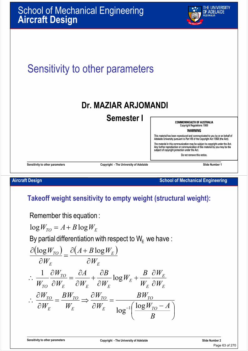
School of Mechanical EngineeringAircraft Design
Sensitivity to other parameters
Dr. MAZIAR ARJOMANDI
Semester I
Sensitivity to other parameters Copyright - The University of Adelaide Slide Number 1
Semester I
Aircraft Design School of Mechanical Engineering
Takeoff weight sensitivity to empty weight (structural weight):
+= WBAW ETO loglog
:have weW torespect withationdifferenti partialBy
:equation this Remember
( ) ( )
∂∂
∂∂
+∂∂
+∂∂
=∂∂
∴
∂+∂
=∂
∂
BWWBWW
W
W
W
BW
W
B
W
A
W
W
W
W
WBA
W
W
E
E
E
E
EEE
TO
TO
E
E
E
TO
log1
loglog
:have weW torespect withationdifferenti partialBy E
Sensitivity to other parameters Copyright - The University of Adelaide Slide Number 2
−=
∂∂
⇒=∂∂
∴−
B
AW
BW
W
W
W
BW
W
W
TO
TO
E
TO
E
TO
E
TO
loglog 1
Page 63 of 270

Aircraft Design School of Mechanical Engineering
Takeoff weight sensitivity to range, endurance, speed, SFC,
propeller efficiency and L/D
:equation this Remember
y
DBW
y
CBW
WTOTO
TO ∂∂
−∂∂
=∂
2
( )
( ) ( )( )( )
( )
:but parameterany isy If
y
WW
y
D
y
MM
y
MMM
y
C
DWBC
yy
y
W
crewPL
ff
reserve
Funuseableffreserve
TO
TO
=∂+∂
=∂∂
∂
∂+=
∂
−−⋅+−∂=
∂∂
−⋅−∂∂
=∂∂
0
1111
1
payloadnot
Sensitivity to other parameters Copyright - The University of Adelaide Slide Number 3
: calculate sLet'y
M
yy
ff
∂
∂
=∂
=∂
0
Aircraft Design School of Mechanical Engineering
Intentionally left blank for your notes
………………………………………………………………………………………………
………………………………………………………………………………………………
………………………………………………………………………………………………
………………………………………………………………………………………………………………………………………………………………………………………………
………………………………………………………………………………………………
………………………………………………………………………………………………
………………………………………………………………………………………………
………………………………………………………………………………………………
………………………………………………………………………………………………
………………………………………………………………………………………………
………………………………………………………………………………………………
………………………………………………………………………………………………
………………………………………………………………………………………………
Sensitivity to other parameters Copyright - The University of Adelaide Slide Number 4
………………………………………………………………………………………………
………………………………………………………………………………………………
………………………………………………………………………………………………
………………………………………………………………………………………………
………………………………………………………………………………………………
………………………………………………………………………………………….
Page 64 of 270
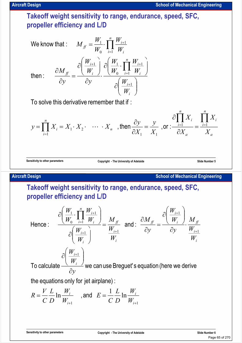
Aircraft Design School of Mechanical Engineering
Takeoff weight sensitivity to range, endurance, speed, SFC,
propeller efficiency and L/D
n
n
i i
iff
WWW
W
W
W
WM ∏
=
+
⋅=1
1
0
1 :that know We
nn
i
i
n
i i
i
i
i
ff
XX
W
W
W
W
W
W
y
W
W
y
M
∏∏
∏
+
=
++
∂
∂
⋅∂
⋅∂
∂
=∂
∂
1
1
1
0
11
:ifthat remember derivative this solve To
:then
Sensitivity to other parameters Copyright - The University of Adelaide Slide Number 5
a
i
i
a
i
i
n
n
i
iX
X
X
X
X
y
X
yXXXXy
∏∏∏ ==
=
=∂
∂=
∂∂
⋅⋅⋅== 11
11
21
1
:or, then , ⋯
Aircraft Design School of Mechanical Engineering
Takeoff weight sensitivity to range, endurance, speed, SFC,
propeller efficiency and L/D
1
1
1
1
1
0
1
+
+
+
=
+
⋅∂
∂
=∂
∂=
⋅∂ ∏
i
ffi
i
ff
i
ff
n
i i
i
W
M
y
W
W
y
M
W
M
W
W
W
W
W
:and :Hence
1
111
+
+++
∂
∂
∂∂
∂
i
i
i
i
i
i
i
i
y
W
W
W
Wyy
W
W
W
W
:airplane)jet foronly equations the
derive we(here equation sBreguet' use can we calculate To
Sensitivity to other parameters Copyright - The University of Adelaide Slide Number 6
11
ln1
ln++
==i
i
i
i
W
W
D
L
CE
W
W
D
L
C
VR and ,
Page 65 of 270

Aircraft Design School of Mechanical Engineering
Takeoff weight sensitivity to range, endurance, speed, SFC,
propeller efficiency and L/D
( ) ( ) and
:have wethen and define weIf
==
==
−−
++
LECEVLRCR
W
WE
W
WR
i
i
i
i
11
11
lnln
( ) ( )
:them replace weif and yyy
:then or :use can wey
find To
and
⋅∂∂
−=⋅∂∂
−=
∂∂
==
∂∂
==
+−+
−+
+
+
−−
W
WRe
R
W
W
eW
We
W
W
W
W
DLECE
DVLRCR
i
iR
i
i
R
i
iR
i
i
i
i
11
1
1
1
11
Sensitivity to other parameters Copyright - The University of Adelaide Slide Number 7
yy and
yy ∂∂
−=
∂∂
∂∂
−=
∂∂ ++++ E
W
W
W
WR
W
W
W
W
i
i
i
i
i
i
i
i 1111
Aircraft Design School of Mechanical Engineering
Intentionally left blank for your notes
………………………………………………………………………………………………
………………………………………………………………………………………………
………………………………………………………………………………………………
………………………………………………………………………………………………………………………………………………………………………………………………
………………………………………………………………………………………………
………………………………………………………………………………………………
………………………………………………………………………………………………
………………………………………………………………………………………………
………………………………………………………………………………………………
………………………………………………………………………………………………
………………………………………………………………………………………………
………………………………………………………………………………………………
………………………………………………………………………………………………
Sensitivity to other parameters Copyright - The University of Adelaide Slide Number 8
………………………………………………………………………………………………
………………………………………………………………………………………………
………………………………………………………………………………………………
………………………………………………………………………………………………
………………………………………………………………………………………………
………………………………………………………………………………………….
Page 66 of 270
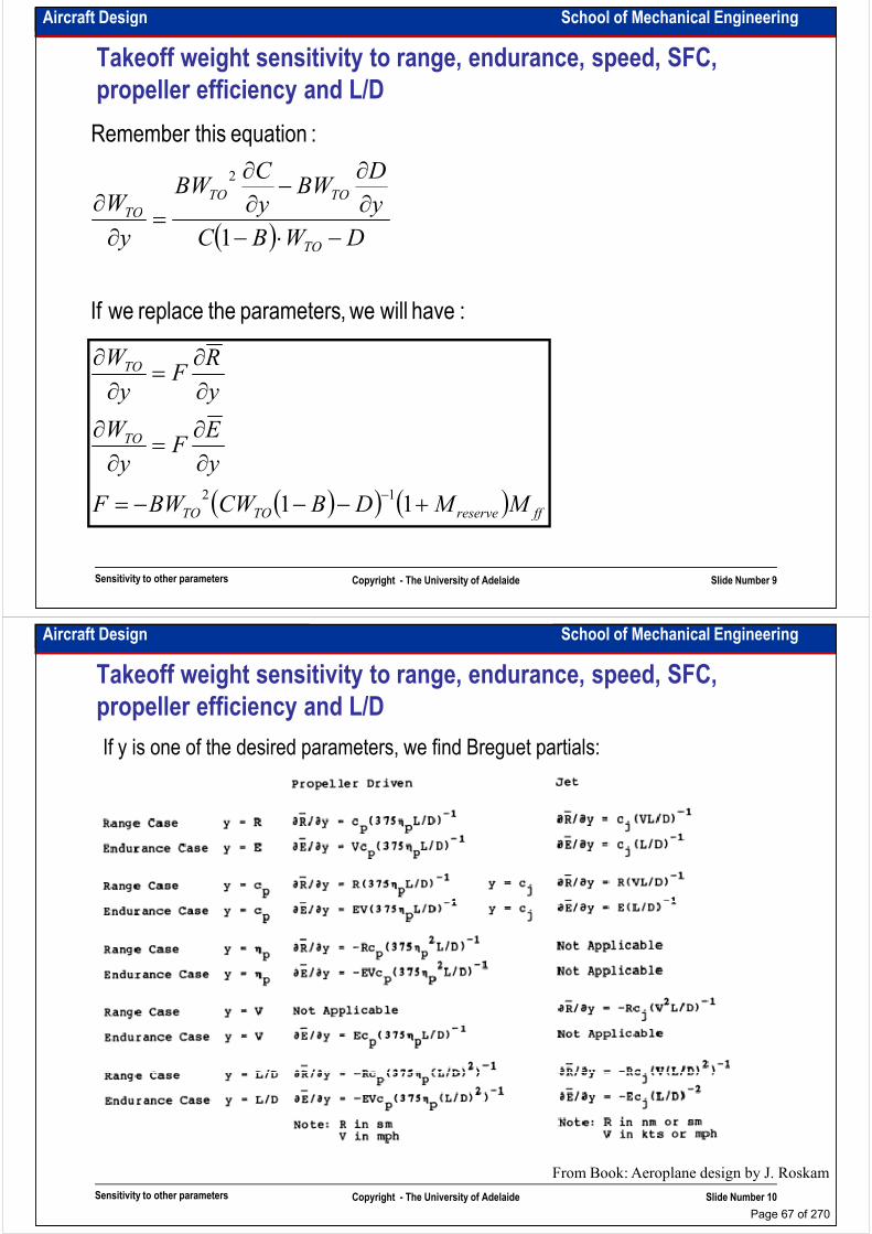
Aircraft Design School of Mechanical Engineering
Takeoff weight sensitivity to range, endurance, speed, SFC,
propeller efficiency and L/D
:equation this Remember
y
DBW
y
CBW
WTOTO
TO ∂∂
−∂∂
=∂
2
( )
:have will we,parameters the replace weIf
DWBC
yy
y
W
TO
TO
−⋅−∂∂
=∂∂
1
TO
y
RF
y
W
∂∂
=∂∂
Sensitivity to other parameters Copyright - The University of Adelaide Slide Number 9
( )( ) ( ) ffreserveTOTO
TO
MMDBCWBWF
y
EF
y
W
+−−−=
∂∂
=∂∂
−11
12
Aircraft Design School of Mechanical Engineering
Takeoff weight sensitivity to range, endurance, speed, SFC,
propeller efficiency and L/D
If y is one of the desired parameters, we find Breguet partials:
Sensitivity to other parameters Copyright - The University of Adelaide Slide Number 10
From Book: Aeroplane design by J. Roskam
Page 67 of 270

Aircraft Design School of Mechanical Engineering
Example 2: A jet transport
• A jet transport aircraft with the following parameters is given. Calculate aircraft
takeoff weight and it’s sensitivity to the aircraft main parameters.
Payload: 300 passengers
Crew: 2 pilots and 8 flight attendantsCrew: 2 pilots and 8 flight attendants
Range: 7000km followed by 1 hour loiter and a 150km flight to alternate
Cruise speed: M=0.83 at 35000ft
Flight altitude: 35000ft
Climb: direct to 35000ft at 2000fpm
Propulsion system: 2 turbofans
Sensitivity to other parameters Copyright - The University of Adelaide Slide Number 11
Aircraft Design School of Mechanical Engineering
Intentionally left blank for your notes
………………………………………………………………………………………………
………………………………………………………………………………………………
………………………………………………………………………………………………
………………………………………………………………………………………………………………………………………………………………………………………………
………………………………………………………………………………………………
………………………………………………………………………………………………
………………………………………………………………………………………………
………………………………………………………………………………………………
………………………………………………………………………………………………
………………………………………………………………………………………………
………………………………………………………………………………………………
………………………………………………………………………………………………
………………………………………………………………………………………………
Sensitivity to other parameters Copyright - The University of Adelaide Slide Number 12
………………………………………………………………………………………………
………………………………………………………………………………………………
………………………………………………………………………………………………
………………………………………………………………………………………………
………………………………………………………………………………………………
………………………………………………………………………………………….
Page 68 of 270
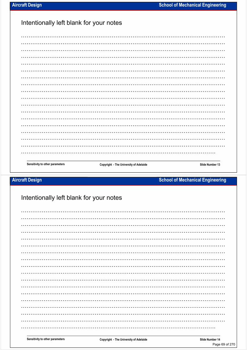
Aircraft Design School of Mechanical Engineering
Intentionally left blank for your notes
………………………………………………………………………………………………
………………………………………………………………………………………………
………………………………………………………………………………………………
………………………………………………………………………………………………………………………………………………………………………………………………
………………………………………………………………………………………………
………………………………………………………………………………………………
………………………………………………………………………………………………
………………………………………………………………………………………………
………………………………………………………………………………………………
………………………………………………………………………………………………
………………………………………………………………………………………………
………………………………………………………………………………………………
………………………………………………………………………………………………
Sensitivity to other parameters Copyright - The University of Adelaide Slide Number 13
………………………………………………………………………………………………
………………………………………………………………………………………………
………………………………………………………………………………………………
………………………………………………………………………………………………
………………………………………………………………………………………………
………………………………………………………………………………………….
Aircraft Design School of Mechanical Engineering
Intentionally left blank for your notes
………………………………………………………………………………………………
………………………………………………………………………………………………
………………………………………………………………………………………………
………………………………………………………………………………………………………………………………………………………………………………………………
………………………………………………………………………………………………
………………………………………………………………………………………………
………………………………………………………………………………………………
………………………………………………………………………………………………
………………………………………………………………………………………………
………………………………………………………………………………………………
………………………………………………………………………………………………
………………………………………………………………………………………………
………………………………………………………………………………………………
Sensitivity to other parameters Copyright - The University of Adelaide Slide Number 14
………………………………………………………………………………………………
………………………………………………………………………………………………
………………………………………………………………………………………………
………………………………………………………………………………………………
………………………………………………………………………………………………
………………………………………………………………………………………….
Page 69 of 270

School of Mechanical EngineeringAircraft Design
Standard requirements
Dr. MAZIAR ARJOMANDI
Semester I
Standard requirements Copyright - The University of Adelaide Slide Number 1
Semester I
Aircraft Design School of Mechanical Engineering
Standard types:
• In this course following types of the standards are introduced:
– General standards
• Technical (ASTM, IEEE, …)
• Organisational (ISO, EFQM, …)• Organisational (ISO, EFQM, …)
– Aviation standards
• Technical (FAR, JAR, AP, MIL, …)
• Organisational (ICAO, FAR, JAR, …)
Standard requirements Copyright - The University of Adelaide Slide Number 2
Don’t Forget that in these days it’s impossible to design,
make and fly an aircraft disregard the standards
Page 70 of 270
Aircraft Design School of Mechanical Engineering
General technical standards:
• These standards focus on manufacturing process and technical properties of a
detail or component.
• They are the best sources of experimental analysis of the parts
• ASTM was established by American Society for Testing and Materials and covers • ASTM was established by American Society for Testing and Materials and covers
nearly 12000 standards. It is the biggest mechanical standard database in the
world.
• IEEE was established by Institute of Electrical & Electronics Engineering.
• A lot of other standard databases are also available. Those were mentioned just as
the examples. Some of them were collected by independent organisations like
ASTM, IEEE, DIN, GOST, …. Some of them were collected by industries like OST,
NACA, ATA, ….
Standard requirements Copyright - The University of Adelaide Slide Number 3
NACA, ATA, ….
Aircraft Design School of Mechanical Engineering
General organisational standards:
• These standards focus on organisational behaviour and relationship
• Some of them are very universal and some are quite specific
• ISO was established by International Organisation for Standardisation. It has
different parts and is upgraded continuouslydifferent parts and is upgraded continuously
• EFQM (European Foundation for Quality Management) and TQM (Total
Quality Management) are the models for assessing the excellence of the
organisations. They introduce novel techniques for self assessment and
benchmarking the companies as well as the ways for improvement
Standard requirements Copyright - The University of Adelaide Slide Number 4
Page 71 of 270
Aircraft Design School of Mechanical Engineering
Aviation standards:
• As an example we study only FAR. The others are similar.
• ICAO (International Civil Aviation Organisation) and IATA (International Aviation
Transport Association) are more related to air transport safety system. These
standards regulate flight routes, aircraft noise and emissions, airport categories and standards regulate flight routes, aircraft noise and emissions, airport categories and
so on
• FAR (Federal Aviation Regulation) was established by FAA (Federal Aviation
Authority), JAR (Joint Aviation Regulation) was established by JAA (Joint Aviation
Authority) are the most common civil aviation standards in the world. They are
technical and organisational standards. MIL is most common military aviation
standard.
• In Australia CASA (Civil Aviation Safety Authority) is responsible for aviation
Standard requirements Copyright - The University of Adelaide Slide Number 5
standardisation
Aircraft Design School of Mechanical Engineering
FAR (Federal Aviation Regulation):
• Has been used for more than 60 years.
• Covers nearly all the types of civil flying vehicles
• Covers design, manufacturing and operation of flying vehicles as well as
organisational regulations.organisational regulations.
• It is audited, controlled and updated by FAA – a US governmental structure.
• It is recognised nearly in all the countries
Standard requirements Copyright - The University of Adelaide Slide Number 6
Page 72 of 270
Aircraft Design School of Mechanical Engineering
FAR main parts:
• Part 21 - Certification procedures for products and parts
• Part 23 - Airworthiness standards: Normal, utility, acrobatic, and commuter category airplanes
• Part 25 - Airworthiness standards: Transport category airplanes
• Part 27 - Airworthiness standards: Normal category rotorcraft • Part 27 - Airworthiness standards: Normal category rotorcraft
• Part 29 - Airworthiness standards: Transport category rotorcraft
• Part 31 - Airworthiness standards: Manned free balloons
• Part 33 - Airworthiness standards: Aircraft engines
• Part 35 - Airworthiness standards: Propellers
• Part 36 - Noise standards: Aircraft type and airworthiness certification
• Part 43 - Maintenance, preventive maintenance, rebuilding, and alteration
• Part 45 - Identification and registration marking
• Part 47 - Aircraft registration
Standard requirements Copyright - The University of Adelaide Slide Number 7
• Part 47 - Aircraft registration
• Part 61 - Certification: Pilots, flight instructors, and ground instructors
• Part 101 - Moored balloons, kites, unmanned rockets and unmanned free balloons
• Part 103 - Ultralight vehicles
• Part 105 - Parachute Operations
Aircraft Design School of Mechanical Engineering
FAR-Part 21: Certification procedures for products and parts
• Subpart A - General
• Subpart B - Type Certificates
• Subpart C - Provisional Type Certificates
• Subpart D - Changes to Type Certificates
• Subpart E - Supplemental Type Certificates • Subpart E - Supplemental Type Certificates
• Subpart F - Production Under Type Certificate Only
• Subpart G - Production Certificates
• Subpart H - Airworthiness Certificates
• Subpart I - Provisional Airworthiness Certificates
• Subpart J - Delegation Option Authorization Procedures
• Subpart K - Approval of Materials, Parts, Processes, and Appliances
• Subpart L - Export Airworthiness Approvals
Standard requirements Copyright - The University of Adelaide Slide Number 8
• Subpart L - Export Airworthiness Approvals
• Subpart M - Designated Alteration Station Authorization Procedures
• Subpart N - Approval of Engines, Propellers, Materials, Parts, and Appliances: Import
• Subpart O - Technical Standard Order Authorizations
Page 73 of 270
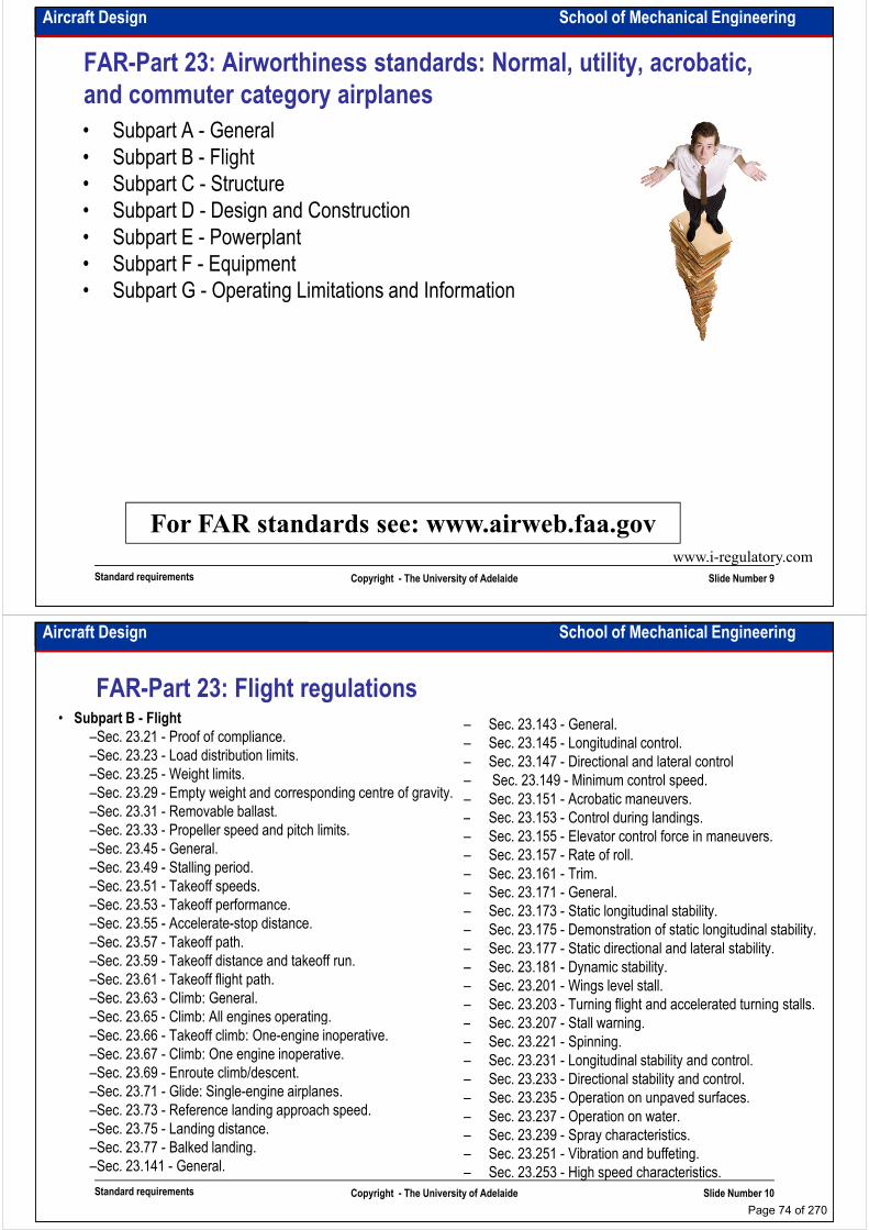
Aircraft Design School of Mechanical Engineering
FAR-Part 23: Airworthiness standards: Normal, utility, acrobatic,
and commuter category airplanes
• Subpart A - General
• Subpart B - Flight
• Subpart C - Structure
• Subpart D - Design and Construction • Subpart D - Design and Construction
• Subpart E - Powerplant
• Subpart F - Equipment
• Subpart G - Operating Limitations and Information
Standard requirements Copyright - The University of Adelaide Slide Number 9
For FAR standards see: www.airweb.faa.govwww.i-regulatory.com
Aircraft Design School of Mechanical Engineering
FAR-Part 23: Flight regulations• Subpart B - Flight
–Sec. 23.21 - Proof of compliance.
–Sec. 23.23 - Load distribution limits.
–Sec. 23.25 - Weight limits.
–Sec. 23.29 - Empty weight and corresponding centre of gravity.
–Sec. 23.31 - Removable ballast.
–Sec. 23.33 - Propeller speed and pitch limits.
– Sec. 23.143 - General.
– Sec. 23.145 - Longitudinal control.
– Sec. 23.147 - Directional and lateral control
– Sec. 23.149 - Minimum control speed.
– Sec. 23.151 - Acrobatic maneuvers.
– Sec. 23.153 - Control during landings. –Sec. 23.33 - Propeller speed and pitch limits.
–Sec. 23.45 - General.
–Sec. 23.49 - Stalling period.
–Sec. 23.51 - Takeoff speeds.
–Sec. 23.53 - Takeoff performance.
–Sec. 23.55 - Accelerate-stop distance.
–Sec. 23.57 - Takeoff path.
–Sec. 23.59 - Takeoff distance and takeoff run.
–Sec. 23.61 - Takeoff flight path.
–Sec. 23.63 - Climb: General.
–Sec. 23.65 - Climb: All engines operating.
– Sec. 23.153 - Control during landings.
– Sec. 23.155 - Elevator control force in maneuvers.
– Sec. 23.157 - Rate of roll.
– Sec. 23.161 - Trim.
– Sec. 23.171 - General.
– Sec. 23.173 - Static longitudinal stability.
– Sec. 23.175 - Demonstration of static longitudinal stability.
– Sec. 23.177 - Static directional and lateral stability.
– Sec. 23.181 - Dynamic stability.
– Sec. 23.201 - Wings level stall.
– Sec. 23.203 - Turning flight and accelerated turning stalls.
– Sec. 23.207 - Stall warning.
Standard requirements Copyright - The University of Adelaide Slide Number 10
–Sec. 23.65 - Climb: All engines operating.
–Sec. 23.66 - Takeoff climb: One-engine inoperative.
–Sec. 23.67 - Climb: One engine inoperative.
–Sec. 23.69 - Enroute climb/descent.
–Sec. 23.71 - Glide: Single-engine airplanes.
–Sec. 23.73 - Reference landing approach speed.
–Sec. 23.75 - Landing distance.
–Sec. 23.77 - Balked landing.
–Sec. 23.141 - General.
– Sec. 23.207 - Stall warning.
– Sec. 23.221 - Spinning.
– Sec. 23.231 - Longitudinal stability and control.
– Sec. 23.233 - Directional stability and control.
– Sec. 23.235 - Operation on unpaved surfaces.
– Sec. 23.237 - Operation on water.
– Sec. 23.239 - Spray characteristics.
– Sec. 23.251 - Vibration and buffeting.
– Sec. 23.253 - High speed characteristics.
Page 74 of 270

Aircraft Design School of Mechanical Engineering
MIL regulation example list:
• MIL-F-8785C Flying Qualities of Piloted Airplanes
• MIL-F-83300 Flying Qualities of Piloted V/STOL Aircraft
• MIL-F-9490 Flight Control Systems-Design, Installation and Test of Piloted Aircraft
• MIL-S-8369 Stall/Post-Stall/Spin Flight Test Demonstration Requirements for Airplanes
• MIL-C-18244 Control and Stabilization Systems: Automatic, Piloted Aircraft
• MIL-D-8708 Demonstration Requirements for Airplanes
• MIL-C-5011 Charts; Standard Aircraft Characteristics and Performance (known as SAC Charts)
• MIL-STD-881 Work Breakdown Structure (WBS)
• MIL-A-8860 through 8864 and 8870: Airplane Strength and Rigidity
• MIL-P-26366 Propellers, Type Test of
• MIL-I-8700 Installation and Test of Electronics Equipment in Aircraft
Standard requirements Copyright - The University of Adelaide Slide Number 11
• MIL-I-8700 Installation and Test of Electronics Equipment in Aircraft
• MIL-S-18471 Seat System, Ejectable, Aircraft
• MIL-W-25140 Weight and Balance Control data
• MIL-STD-757 Reliability evaluation from Demonstration Data
Aircraft Design School of Mechanical Engineering
Intentionally left blank for your notes
………………………………………………………………………………………………
………………………………………………………………………………………………
………………………………………………………………………………………………
………………………………………………………………………………………………………………………………………………………………………………………………
………………………………………………………………………………………………
………………………………………………………………………………………………
………………………………………………………………………………………………
………………………………………………………………………………………………
………………………………………………………………………………………………
………………………………………………………………………………………………
………………………………………………………………………………………………
………………………………………………………………………………………………
………………………………………………………………………………………………
Standard requirements Copyright - The University of Adelaide Slide Number 12
………………………………………………………………………………………………
………………………………………………………………………………………………
………………………………………………………………………………………………
………………………………………………………………………………………………
………………………………………………………………………………………………
………………………………………………………………………………………….
Page 75 of 270

School of Mechanical EngineeringAircraft Design
First estimation of aircraft design parameters
Dr. MAZIAR ARJOMANDI
Semester I
First estimation of aircraft design
parameters
Copyright - The University of Adelaide Slide Number 1
Semester I
Aircraft Design School of Mechanical Engineering
Thrust-to-weight ratio and wing loading:
• Are the two most important parameters affecting aircraft performance
• Need to be optimised
• More credible estimation of them reduces design workload
• Interconnected for a number of performance calculations
• Generally we use TT for performance requirements.
• It is difficult to use historical data to select them.
• The aircraft is sized for
1- stall speed,
2- takeoff distance, landing distance,
3- climb,
First estimation of aircraft design
parametersCopyright - The University of Adelaide Slide Number 2
3- climb,
4- cruise,
5- flight ceiling,
6-maneuver load factor,
7- time for acceleration and …
Page 76 of 270

Aircraft Design School of Mechanical Engineering
Thrust-to-weight ratio:
• T/W directly affects the aircraft performance.
• T/W is not constant and varies during flight as aircraft fuel is burned and thrust varies
with altitude and velocity.
• A designer generally uses T/W at sea level, standard day condition at design takeoff • A designer generally uses T/W at sea level, standard day condition at design takeoff
weight and maximum throttle setting .
• It is important not to confuse T/W for different configurations like: idle throttle setting,
afterburner engines, combat configuration and partial power setting.
• Thrust to weight or thrust loading is associated with the jet-engined aircraft. For propeller
powered power loading is used
• Power loading is W/hp. Try not to confuse it with horsepower-to-weight ratio.
• We can use following expression to find equivalent T/W for propellered aircraft (W in lb)
First estimation of aircraft design
parametersCopyright - The University of Adelaide Slide Number 3
=W
hp
VW
T Pη550
Aircraft Design School of Mechanical Engineering
Statistical estimations for T/W and hp/W
Aircraft type T/W
Jet trainer 0.4-0.5
Aircraft type hp/W w/hp
Powered sailplane 0.04 25 Jet trainer 0.4-0.5
Jet fighter (dog fighter) 0.7-1.1
Jet fighter (other) 0.5-0.8
Military cargo / bomber 0.25-0.4
Jet transport 0.25-0.3
Homebuilt 0.08 12
GA – single engine 0.07 14
GA – twin engine 0.17 6
Agricultural 0.09 11
Twin turboprop 0.20 5
First estimation of aircraft design
parametersCopyright - The University of Adelaide Slide Number 4
From Book: Aircraft design; a conceptual approach, by D. Raymer
Twin turboprop 0.20 5
Flying boat 0.10 10
Page 77 of 270
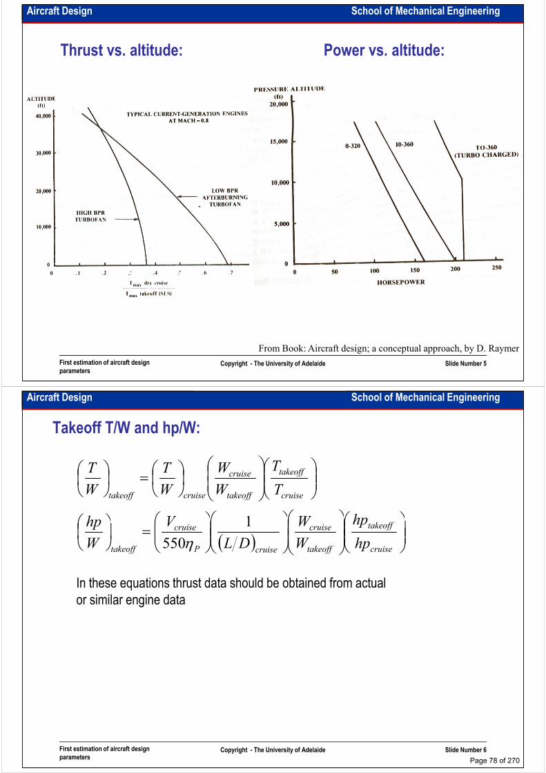
Aircraft Design School of Mechanical Engineering
Thrust vs. altitude: Power vs. altitude:
First estimation of aircraft design
parametersCopyright - The University of Adelaide Slide Number 5
From Book: Aircraft design; a conceptual approach, by D. Raymer
Aircraft Design School of Mechanical Engineering
Takeoff T/W and hp/W:
=
cruise
takeoff
takeoff
cruise
cruisetakeoff
hpWVhp
T
T
W
W
W
T
W
T
1
( )
=
cruise
takeoff
takeoff
cruise
cruiseP
cruise
takeoff hp
hp
W
W
DL
V
W
hp 1
550η
In these equations thrust data should be obtained from actual
or similar engine data
First estimation of aircraft design
parametersCopyright - The University of Adelaide Slide Number 6
Page 78 of 270

Aircraft Design School of Mechanical Engineering
Wing loading
• W/S directly affects the aircraft performance.
• W/S is not constant and varies during flight as aircraft fuel is burned.
• A designer generally uses W/S at design takeoff weight.
• It is important not to confuse W/S for different configurations like: combat configuration.
Aircraft type W/S (lb/ft2)
Sailplane 6
Homebuilt 11
GA – single engine 17
GA – twin engine 26
Aircraft type W/S (dN/m2)
GA 100-180
Fighter 280-350
Transport 600-1000
Statistical estimation for wing loading:
First estimation of aircraft design
parametersCopyright - The University of Adelaide Slide Number 7
Twin turboprop 40
Jet trainer 50
Jet fighter 70
Jet Transport / bomber 120
Aircraft Design School of Mechanical Engineering
T/W and W/S facts: Different typesWing Loading / Disc Loading (Average)
600
700
Wing Loading (kg/m^2)
200
300
400
500
Wing Loading (kg/m^2)
First estimation of aircraft design
parametersCopyright - The University of Adelaide Slide Number 8
0
100
General -
Agricultural
General -
Aviation
Military -
Fighter
Military -
Bomber
Civil - Short
Range
Civil - Long
Range
Helicopter -
Cargo
Helicopter -
Attack
Helicopter -
Utility
Helicopter -
Light Utility
Aircraft Type
From Report: World Aircraft Statistics by Fletcher, Holms, Schwarz, Slattery
Page 79 of 270
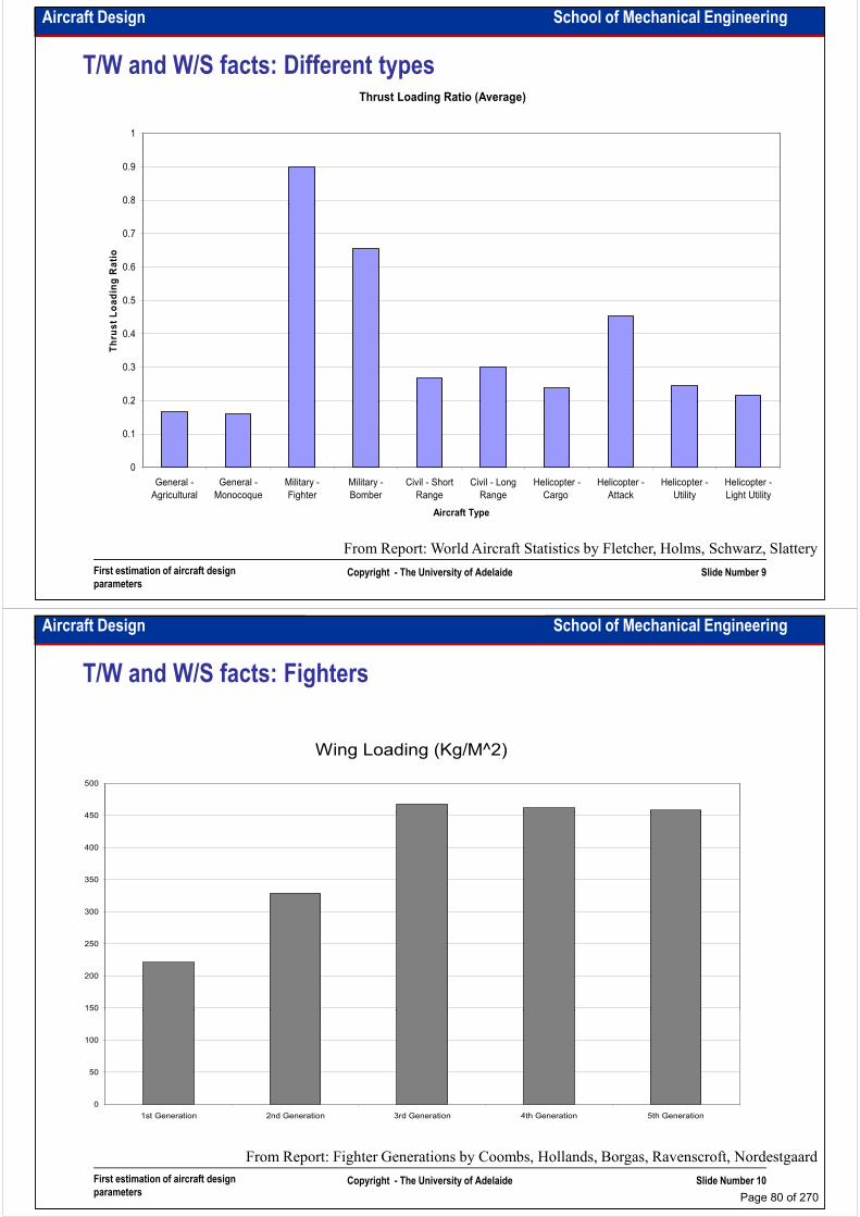
Aircraft Design School of Mechanical Engineering
T/W and W/S facts: Different typesThrust Loading Ratio (Average)
0.8
0.9
1
0.2
0.3
0.4
0.5
0.6
0.7
0.8
Thrust Loading Ratio
First estimation of aircraft design
parametersCopyright - The University of Adelaide Slide Number 9
From Report: World Aircraft Statistics by Fletcher, Holms, Schwarz, Slattery
0
0.1
0.2
General -
Agricultural
General -
Monocoque
Military -
Fighter
Military -
Bomber
Civil - Short
Range
Civil - Long
Range
Helicopter -
Cargo
Helicopter -
Attack
Helicopter -
Utility
Helicopter -
Light Utility
Aircraft Type
Aircraft Design School of Mechanical Engineering
T/W and W/S facts: Fighters
Wing Loading (Kg/M^2)
450
500
150
200
250
300
350
400
450
First estimation of aircraft design
parametersCopyright - The University of Adelaide Slide Number 10
From Report: Fighter Generations by Coombs, Hollands, Borgas, Ravenscroft, Nordestgaard
0
50
100
150
1st Generation 2nd Generation 3rd Generation 4th Generation 5th Generation
Page 80 of 270
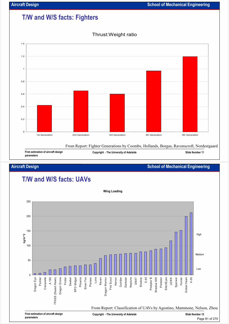
Aircraft Design School of Mechanical Engineering
T/W and W/S facts: Fighters
Thrust:Weight ratio
1.4
0.4
0.6
0.8
1
1.2
First estimation of aircraft design
parametersCopyright - The University of Adelaide Slide Number 11
From Report: Fighter Generations by Coombs, Hollands, Borgas, Ravenscroft, Nordestgaard
0
0.2
0.4
1st Generation 2nd Generation 3rd Generation 4th Generation 5th Generation
Aircraft Design School of Mechanical Engineering
T/W and W/S facts: UAVs
Wing Loading
200
250
50
100
150
200
kg/m^2
Low
Medium
High
First estimation of aircraft design
parametersCopyright - The University of Adelaide Slide Number 12
From Report: Classification of UAVs by Agostino, Mammone, Nelson, Zhou
0
Dragon Eye
Pointer
Crecerelle
A 160
FPASS (Desert Hawk)
Dragon Drone
Finder
Seeker
RPO Midget
Phoenix
Silver Fox
Pioneer
Luna
Raven
Dragon Warrior
Fire Scout
Herron
Outrider
Darkstar
Neptune
GNAT
Shadow
X-45
Predator B
Shadow 600
Predator
SilentEyes
LEWK
Sperwer
Hunter
Global Hawk
X-50
Low
Page 81 of 270

Aircraft Design School of Mechanical Engineering
T/W and W/S facts:
• Long-range commercial aircraft tend to have a higher wing loading to
maximise their range. They use very effective high lift devices on takeoff and
landing.
• Combat aircraft tend to have lower wing loading and higher thrust loading • Combat aircraft tend to have lower wing loading and higher thrust loading
(especially with afterburner) to provide better manoeuvrability.
• GA and agricultural aircraft tend to have lower wing loading to have less
takeoff and landing distance.
• Less wing loading provides less comfort in cruise flight due to turbulent and
gusts.
• High-altitude and gliding aircraft require low wing loading.
First estimation of aircraft design
parametersCopyright - The University of Adelaide Slide Number 13
In these days we usually design multipurpose aircraft with
more than one principle mission, so it is required to select
a proper wing loading for all mission objectives
Aircraft Design School of Mechanical Engineering
Intentionally left blank for your notes
………………………………………………………………………………………………
………………………………………………………………………………………………
………………………………………………………………………………………………
………………………………………………………………………………………………………………………………………………………………………………………………
………………………………………………………………………………………………
………………………………………………………………………………………………
………………………………………………………………………………………………
………………………………………………………………………………………………
………………………………………………………………………………………………
………………………………………………………………………………………………
………………………………………………………………………………………………
………………………………………………………………………………………………
………………………………………………………………………………………………
First estimation of aircraft design
parametersCopyright - The University of Adelaide Slide Number 14
………………………………………………………………………………………………
………………………………………………………………………………………………
………………………………………………………………………………………………
………………………………………………………………………………………………
………………………………………………………………………………………………
………………………………………………………………………………………….
Page 82 of 270

School of Mechanical EngineeringAircraft Design
Sizing to stall speed requirements
Dr. MAZIAR ARJOMANDI
Semester I
Sizing to stall speed requirements Copyright - The University of Adelaide Slide Number 1
Semester I
Aircraft Design School of Mechanical Engineering
Standard requirements:
• FAR23 (for aircraft less than 12500lb) certified aircraft may not have a stall speed greater
than 61kts at WTO.
• FAR23 multi-engined aircraft must meet certain climb gradient.
• It is not stated in any design specification but a stall speed of 50knots would be considered
the upper limit for an aircraft to be operated by a low-time pilot.the upper limit for an aircraft to be operated by a low-time pilot.
• No specific stall requirements for FAR25 certified aircraft, but more stall speed means more
takeoff and landing distance.
• For civil application the approach speed is 1.3 times the stall speed.
• For military application the approach speed is 1.15-1.2 times the stall speed.
Stall speed equation:
Recall: 21SCVSCqLW ρ===
Sizing to stall speed requirements Copyright - The University of Adelaide Slide Number 2
Recall:
Then:
max
2
max2
1LstallLstall SCVSCqLW ρ===
max
2
2
1LstallCV
S
Wρ=
Page 83 of 270

Aircraft Design School of Mechanical Engineering
Estimation of CLmax:
• CLmax varies between 1.2-1.5 for a plain wing with no flaps to 4-5 for a wing with large
flaps immersed in the propwash or jetwash.
• For a STOL aircraft CLmax typically is 3.
• For a regular transport aircraft with flaps and slats CLmax is about 2.4.
• CLmax of GA aircraft with flaps on the inner part of the wing is about 1.6-2.
• Maximum lift coefficient depends upon:
– Wing geometry
– Airfoil shape
– Flap geometry, deflection angle and span
– Leading-edge slat, slat geometry and deflection angle
– Reynolds number
Sizing to stall speed requirements Copyright - The University of Adelaide Slide Number 3
– Surface texture
– Interference from other parts of the aircraft such as the fuselage, or nacelles
• Most aircraft use a different flap setting for takeoff and landing (the maximum lift and
drag coefficient for landing is greater than for takeoff).
Aircraft Design School of Mechanical Engineering
Estimation of CLmax:
Airplane type CLmax CLmax (takeoff) CLmax (landing)
Homebuilts 1.2-1.8 1.2-1.8 1.2-2.0
Single Engine Propeller Driven 1.3-1.9 1.3-1.9 1.6-2.3
Twin Engine Propeller Driven 1.2-1.8 1.4-2.0 1.6-2.5 Twin Engine Propeller Driven 1.2-1.8 1.4-2.0 1.6-2.5
Agricultural 1.3-1.9 1.3-1.9 1.3-1.9
Business Jets 1.4-1.8 1.6-2.2 1.6-2.6
Regional Turboprop 1.5-1.9 1.7-2.1 1.9-3.3
Transport Jets 1.2-1.8 1.6-2.2 1.8-2.8
Military Trainers 1.2-1.8 1.4-2.0 1.6-2.2
Fighters 1.2-1.8 1.4-2.0 1.6-2.2
Military Patrol, Bomber and Transport 1.2-1.8 1.6-2.2 1.8-3.0
Flying Boats, Amphibious and Float Airplanes 1.2-1.8 1.6-2.2 1.8-3.4
Sizing to stall speed requirements Copyright - The University of Adelaide Slide Number 4
Flying Boats, Amphibious and Float Airplanes 1.2-1.8 1.6-2.2 1.8-3.4
Supersonic Cruise Airplanes 1.2-1.8 1.6-2.0 1.8-2.2
From Book: Airplane design, by J. Roskam
Page 84 of 270

Aircraft Design School of Mechanical Engineering
Example: A GA aircraft
• Calculate required wing loading for a GA aircraft to have a power-off stall speed of
no more than 80km/h with flaps in landing configuration, 100km/h with flaps in
takeoff configuration and 120km/h with no flaps at sea level and at an altitude of
1000m.
Sizing to stall speed requirements Copyright - The University of Adelaide Slide Number 5
Aircraft Design School of Mechanical Engineering
Intentionally left blank for your notes
………………………………………………………………………………………………
………………………………………………………………………………………………
………………………………………………………………………………………………
………………………………………………………………………………………………………………………………………………………………………………………………
………………………………………………………………………………………………
………………………………………………………………………………………………
………………………………………………………………………………………………
………………………………………………………………………………………………
………………………………………………………………………………………………
………………………………………………………………………………………………
………………………………………………………………………………………………
………………………………………………………………………………………………
………………………………………………………………………………………………
Sizing to stall speed requirements Copyright - The University of Adelaide Slide Number 6
………………………………………………………………………………………………
………………………………………………………………………………………………
………………………………………………………………………………………………
………………………………………………………………………………………………
………………………………………………………………………………………………
………………………………………………………………………………………….
Page 85 of 270
School of Mechanical EngineeringAircraft Design
Sizing to takeoff distance requirements
Dr. MAZIAR ARJOMANDI
Semester I
Sizing to takeoff distance requirements Copyright - The University of Adelaide Slide Number 1
Semester I
Aircraft Design School of Mechanical Engineering
Takeoff distance requirements:
• Review “Aeronautical Engineering I” course notes for terminology.
• To design an aircraft we have to calculate “Takeoff Field Length” or “Balanced Field Length”.
This is the length required to takeoff and clear the specified obstacle (50ft for military or
small civil and 35ft for commercial aircraft) when one engine fails exactly at decision speed.
• For civil aircraft the requirements of FAR23 and FAR25 must be considered. For military • For civil aircraft the requirements of FAR23 and FAR25 must be considered. For military
aircraft the requirements are given in RFP or TT.
• Aerodynamic forces on the ground roll depend mainly upon the pilot techniques.
• Some UAVs use catapult for takeoff with the length of 6-13m. Some of them are able to
takeoff from zero-length catapult. Hand-launched UAV could be launched by hand
Sizing to takeoff distance requirements Copyright - The University of Adelaide Slide Number 2
Page 86 of 270
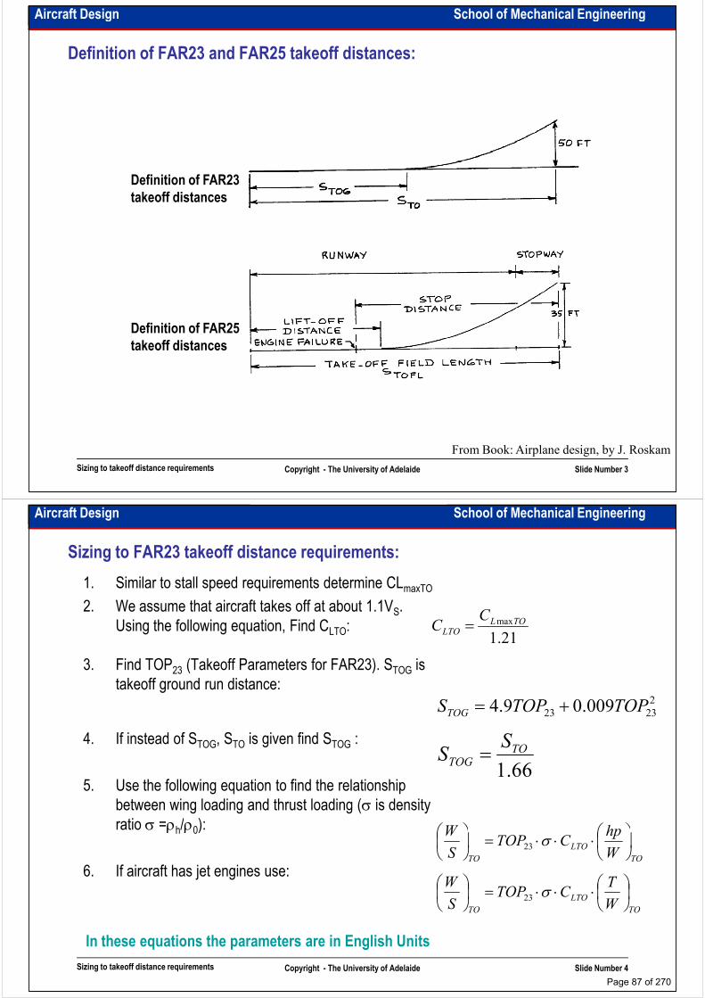
Aircraft Design School of Mechanical Engineering
Definition of FAR23 and FAR25 takeoff distances:
Definition of FAR23
takeoff distances
Definition of FAR25
Sizing to takeoff distance requirements Copyright - The University of Adelaide Slide Number 3
From Book: Airplane design, by J. Roskam
Definition of FAR25
takeoff distances
Aircraft Design School of Mechanical Engineering
Sizing to FAR23 takeoff distance requirements:
1. Similar to stall speed requirements determine CLmaxTO
2. We assume that aircraft takes off at about 1.1VS.
Using the following equation, Find CLTO:
3. Find TOP23 (Takeoff Parameters for FAR23). STOG is
21.1
maxTOLLTO
CC =
3. Find TOP23 (Takeoff Parameters for FAR23). STOG is
takeoff ground run distance:
4. If instead of STOG, STO is given find STOG :
5. Use the following equation to find the relationship
between wing loading and thrust loading (σ is density
ratio σ =ρh/ρ0):
2
2323 009.09.4 TOPTOPSTOG +=
66.1
TOTOG
SS =
hpW
Sizing to takeoff distance requirements Copyright - The University of Adelaide Slide Number 4
ratio σ =ρh/ρ0):
6. If aircraft has jet engines use:
In these equations the parameters are in English Units
TO
LTO
TO W
hpCTOP
S
W
⋅⋅⋅=
σ23
TO
LTO
TO W
TCTOP
S
W
⋅⋅⋅=
σ23
Page 87 of 270
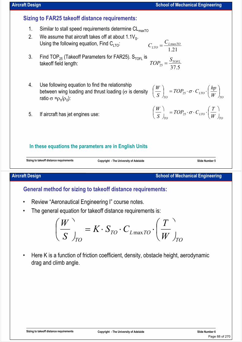
Aircraft Design School of Mechanical Engineering
Sizing to FAR25 takeoff distance requirements:
1. Similar to stall speed requirements determine CLmaxTO
2. We assume that aircraft takes off at about 1.1VS.
Using the following equation, Find CLTO:
3. Find TOP25 (Takeoff Parameters for FAR25). STOFL is
21.1
maxTOLLTO
CC =
S3. Find TOP25 (Takeoff Parameters for FAR25). STOFL is
takeoff field length:
4. Use following equation to find the relationship
between wing loading and thrust loading (σ is density
ratio σ =ρh/ρ0):
5. If aircraft has jet engines use:
5.3725
TOFLSTOP =
TO
LTO
TO W
hpCTOP
S
W
⋅⋅⋅=
σ25
LTO
TCTOP
W
⋅⋅⋅=
σ25
Sizing to takeoff distance requirements Copyright - The University of Adelaide Slide Number 5
5. If aircraft has jet engines use:
In these equations the parameters are in English Units
TO
LTO
TO WCTOP
S
⋅⋅⋅=
σ25
Aircraft Design School of Mechanical Engineering
General method for sizing to takeoff distance requirements:
• Review “Aeronautical Engineering I” course notes.
• The general equation for takeoff distance requirements is:
TCSK
W
⋅⋅⋅=
• Here K is a function of friction coefficient, density, obstacle height, aerodynamic
drag and climb angle.
TO
TOLTO
TO WCSK
S
⋅⋅⋅=
max
Sizing to takeoff distance requirements Copyright - The University of Adelaide Slide Number 6
Page 88 of 270
Aircraft Design School of Mechanical Engineering
Example: FAR 23 takeoff distance sizing
• Size a propeller driven aircraft for takeoff distance of 650m at sea level and at an
altitude of 1000m.
Sizing to takeoff distance requirements Copyright - The University of Adelaide Slide Number 7
Aircraft Design School of Mechanical Engineering
Intentionally left blank for your notes
………………………………………………………………………………………………
………………………………………………………………………………………………
………………………………………………………………………………………………
………………………………………………………………………………………………………………………………………………………………………………………………
………………………………………………………………………………………………
………………………………………………………………………………………………
………………………………………………………………………………………………
………………………………………………………………………………………………
………………………………………………………………………………………………
………………………………………………………………………………………………
………………………………………………………………………………………………
………………………………………………………………………………………………
………………………………………………………………………………………………
Sizing to takeoff distance requirements Copyright - The University of Adelaide Slide Number 8
………………………………………………………………………………………………
………………………………………………………………………………………………
………………………………………………………………………………………………
………………………………………………………………………………………………
………………………………………………………………………………………………
………………………………………………………………………………………….
Page 89 of 270
Aircraft Design School of Mechanical Engineering
Example: FAR 25 takeoff distance sizing
• Size a jet transport aircraft for takeoff field length of 1500m at sea level and at an
altitude of 1500m.
Sizing to takeoff distance requirements Copyright - The University of Adelaide Slide Number 9
Aircraft Design School of Mechanical Engineering
Intentionally left blank for your notes
………………………………………………………………………………………………
………………………………………………………………………………………………
………………………………………………………………………………………………
………………………………………………………………………………………………………………………………………………………………………………………………
………………………………………………………………………………………………
………………………………………………………………………………………………
………………………………………………………………………………………………
………………………………………………………………………………………………
………………………………………………………………………………………………
………………………………………………………………………………………………
………………………………………………………………………………………………
………………………………………………………………………………………………
………………………………………………………………………………………………
Sizing to takeoff distance requirements Copyright - The University of Adelaide Slide Number 10
………………………………………………………………………………………………
………………………………………………………………………………………………
………………………………………………………………………………………………
………………………………………………………………………………………………
………………………………………………………………………………………………
………………………………………………………………………………………….
Page 90 of 270
School of Mechanical EngineeringAircraft Design
Sizing to landing distance requirements
Dr. MAZIAR ARJOMANDI
Semester I
Sizing to landing distance requirements Copyright - The University of Adelaide Slide Number 1
Semester I
Aircraft Design School of Mechanical Engineering
Landing distance requirements:
• Review “Aeronautical Engineering I” course notes for terminology.
• To design an aircraft we have to calculate “Landing Distance”. “Landing Distance”
or “Landing Field Length” is the length required to clear the specified obstacle
(50ft for all aircraft) at approach speed to the time when aircraft comes to (50ft for all aircraft) at approach speed to the time when aircraft comes to
complete stop. Approach speed for civil and military aircraft is 1.3 and 1.2 times
the stall speed respectively.
• For civil aircraft the requirements of FAR23 and FAR25 must be considered. For
military aircraft the requirements are given in RFP or TT.
• Landing distance depends mainly upon the pilot techniques.
• Some UAVs use parachute for landing.
• In the emergency situation an aircraft must be able to land on it’s fuselage (belly
Sizing to landing distance requirements Copyright - The University of Adelaide Slide Number 2
• In the emergency situation an aircraft must be able to land on it’s fuselage (belly
landing)
Page 91 of 270

Aircraft Design School of Mechanical Engineering
Landing weight:
• For most propeller-powered and jet trainers landing weight is equal to takeoff
weight or WL/WTO=1.0.
• For most jet transport aircraft landing weight is about 0.85 times takeoff weight or
W /W =0.85.WL/WTO=0.85.
• For fighters check with TT.
• If landing weight is less than takeoff weight, aircraft must have a special system to
drop the fuel or payload in emergency conditions. It is unlikely to drop the fuel
because of its cost and environmental effects.
• If an aircraft is in emergency condition, it is better to land it with minimum weight.
Sizing to landing distance requirements Copyright - The University of Adelaide Slide Number 3
Aircraft Design School of Mechanical Engineering
Definition of FAR23 and FAR25 landing distances:
Definition of FAR23 Definition of FAR23
landing distances
Definition of FAR25
landing distances
Sizing to landing distance requirements Copyright - The University of Adelaide Slide Number 4
From Book: Airplane design, by J. Roskam
landing distances
Page 92 of 270

Aircraft Design School of Mechanical Engineering
Sizing to FAR23 landing distance requirements:
1. Similar to stall speed requirements determine CLmaxL
2. Statistical data show that if VSL (stall speed in landing
configuration) in knots and SLG (landing ground roll)
in feet then SLG=0.265 VSL2. We have SL=1.938SLG
then using the following equation we can find V : SV 395.1=then using the following equation we can find VSL:
3. Find wing loading for landing configuration:
4. If WL is less than WTO find WL/WTO using the following
equation:
LSLSV 395.1=
LLSL
L
CVS
W
max
2
2
1ρ=
LL
TO
TOS
W
W
W
S
W
=
Sizing to landing distance requirements Copyright - The University of Adelaide Slide Number 5
In these equations the parameters are in English Units
LLTO
Aircraft Design School of Mechanical Engineering
Sizing to FAR25 landing distance requirements:
1. Similar to stall speed requirements determine CLmaxL
2. Statistical data show that if VA (approach speed in
landing configuration) in knots and SFL (field length)
in feet then SFL=0.3 VA2. Using the following equation
find VA: SV 826.1=find VA:
3. Find VSL (stall speed in landing configuration):
4. Find wing loading for landing configuration:
5. If WL is less than WTO find WL/WTO and use the
following equation:
FLASV 826.1=
ASLVV
3.1
1=
TOWWW
=
LLSL
L
CVS
W
max
2
2
1ρ=
Sizing to landing distance requirements Copyright - The University of Adelaide Slide Number 6
following equation:
In these equations the parameters are in English Units
LL
TO
TOS
W
W
W
S
W
=
Page 93 of 270
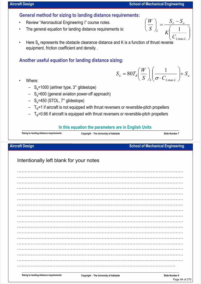
Aircraft Design School of Mechanical Engineering
General method for sizing to landing distance requirements:
• Review “Aeronautical Engineering I” course notes.
• The general equation for landing distance requirements is:
• Here Sa represents the obstacle clearance distance and K is a function of thrust reverse
equipment, friction coefficient and density .
−=
LL
aL
L
CK
SS
S
W
max
1
equipment, friction coefficient and density .
• Where:
– Sa=1000 (airliner type, 3° glideslope)
– Sa=600 (general aviation power-off approach)
a
LLL
RLS
CS
WTS +
⋅
=max
180
σ
Another useful equation for landing distance sizing:
Sizing to landing distance requirements Copyright - The University of Adelaide Slide Number 7
– Sa=600 (general aviation power-off approach)
– Sa=450 (STOL, 7° glideslope)
– TR=1 if aircraft is not equipped with thrust reversers or reversible-pitch propellers
– TR=0.66 if aircraft is equipped with thrust reversers or reversible-pitch propellers
In this equation the parameters are in English Units
Aircraft Design School of Mechanical Engineering
Intentionally left blank for your notes
………………………………………………………………………………………………
………………………………………………………………………………………………
………………………………………………………………………………………………
………………………………………………………………………………………………………………………………………………………………………………………………
………………………………………………………………………………………………
………………………………………………………………………………………………
………………………………………………………………………………………………
………………………………………………………………………………………………
………………………………………………………………………………………………
………………………………………………………………………………………………
………………………………………………………………………………………………
………………………………………………………………………………………………
………………………………………………………………………………………………
Sizing to landing distance requirements Copyright - The University of Adelaide Slide Number 8
………………………………………………………………………………………………
………………………………………………………………………………………………
………………………………………………………………………………………………
………………………………………………………………………………………………
………………………………………………………………………………………………
………………………………………………………………………………………….
Page 94 of 270

Aircraft Design School of Mechanical Engineering
Example: FAR 23 landing distance sizing
• Size a propeller driven aircraft for landing distance of 650m at sea level and at an
altitude of 1500m, WL=0.9WTO.
Sizing to landing distance requirements Copyright - The University of Adelaide Slide Number 9
Aircraft Design School of Mechanical Engineering
Intentionally left blank for your notes
………………………………………………………………………………………………
………………………………………………………………………………………………
………………………………………………………………………………………………
………………………………………………………………………………………………………………………………………………………………………………………………
………………………………………………………………………………………………
………………………………………………………………………………………………
………………………………………………………………………………………………
………………………………………………………………………………………………
………………………………………………………………………………………………
………………………………………………………………………………………………
………………………………………………………………………………………………
………………………………………………………………………………………………
………………………………………………………………………………………………
Sizing to landing distance requirements Copyright - The University of Adelaide Slide Number 10
………………………………………………………………………………………………
………………………………………………………………………………………………
………………………………………………………………………………………………
………………………………………………………………………………………………
………………………………………………………………………………………………
………………………………………………………………………………………….
Page 95 of 270
Aircraft Design School of Mechanical Engineering
Example: FAR 25 landing distance sizing
• Size a jet transport aircraft for landing field length of 2000m at sea level and at an
altitude of 1000m, WL=0.8WTO.
Sizing to landing distance requirements Copyright - The University of Adelaide Slide Number 11
Aircraft Design School of Mechanical Engineering
Intentionally left blank for your notes
………………………………………………………………………………………………
………………………………………………………………………………………………
………………………………………………………………………………………………
………………………………………………………………………………………………………………………………………………………………………………………………
………………………………………………………………………………………………
………………………………………………………………………………………………
………………………………………………………………………………………………
………………………………………………………………………………………………
………………………………………………………………………………………………
………………………………………………………………………………………………
………………………………………………………………………………………………
………………………………………………………………………………………………
………………………………………………………………………………………………
Sizing to landing distance requirements Copyright - The University of Adelaide Slide Number 12
………………………………………………………………………………………………
………………………………………………………………………………………………
………………………………………………………………………………………………
………………………………………………………………………………………………
………………………………………………………………………………………………
………………………………………………………………………………………….
Page 96 of 270
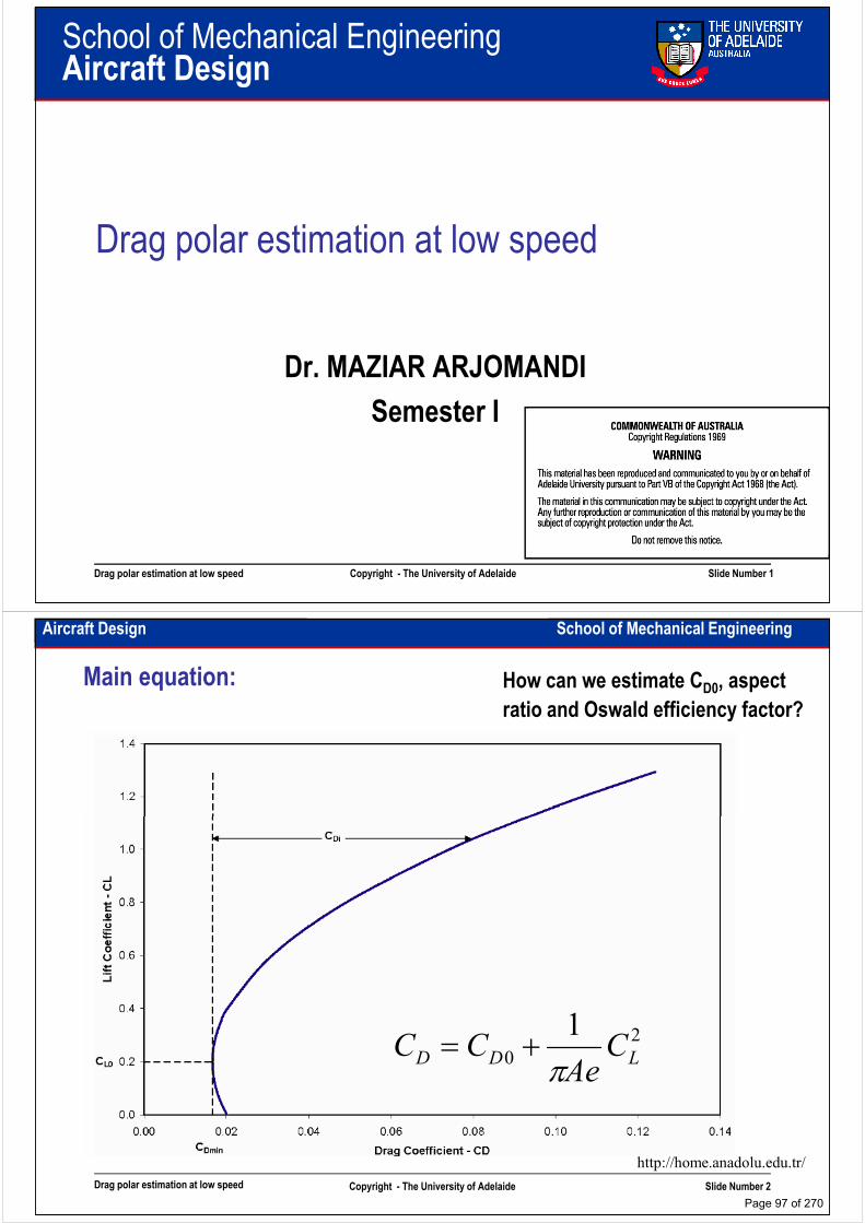
School of Mechanical EngineeringAircraft Design
Drag polar estimation at low speed
Dr. MAZIAR ARJOMANDI
Semester I
Drag polar estimation at low speed Copyright - The University of Adelaide Slide Number 1
Semester I
Aircraft Design School of Mechanical Engineering
Main equation: How can we estimate CD0, aspect
ratio and Oswald efficiency factor?
1
Drag polar estimation at low speed Copyright - The University of Adelaide Slide Number 2
2
0
1LDD C
AeCC
π+=
http://home.anadolu.edu.tr/
Page 97 of 270

Aircraft Design School of Mechanical Engineering
Zero-lift drag coefficient estimation:
• Calculate SWET/SREF using your sketch. If aircraft sketch is not available use statistics.
• We assume that the parasite drag of a well-designed aircraft in subsonic cruise
consists mostly of skin-friction drag plus a small separation pressure drag. “Equivalent
skin friction drag” (Cfe) includes both skin-friction and separation drag.skin friction drag” (Cfe) includes both skin-friction and separation drag.
• For the first estimation of CD0 we can use the following equation:
• Roskam’s method could be used. See 3.4.1 from vol.1. It gives more precise
ref
wetfeDS
SCC =0
Drag polar estimation at low speed Copyright - The University of Adelaide Slide Number 3
• Roskam’s method could be used. See 3.4.1 from vol.1. It gives more precise
estimation of CD0.
Aircraft Design School of Mechanical Engineering
First estimation of SWET/SREF :
8
http://stellarlink.org/
http://www.whiteplanes.com/
http://www.mcchordairmuseum.org/
http://hp.state.sd.us/
http://home.quicknet.nl/
http://www.jda.go.jp/
http://www.globalaircraft.org/
http://www.public.iastate.edu/
http://www.airbroker.se/BOEING 747
B-47
6
4
http://www.airbroker.se/
http://www.aircentre.com.au/
AVRO VULCAN F-102
CESSNA SKYLANE
F-4
F-104
BEECH DUCHESS
BEECH STARSHIP
Drag polar estimation at low speed Copyright - The University of Adelaide Slide Number 4
From Book: Aircraft design; a conceptual approach, by D. Raymer
2
B-49
AVRO VULCAN F-102
Page 98 of 270
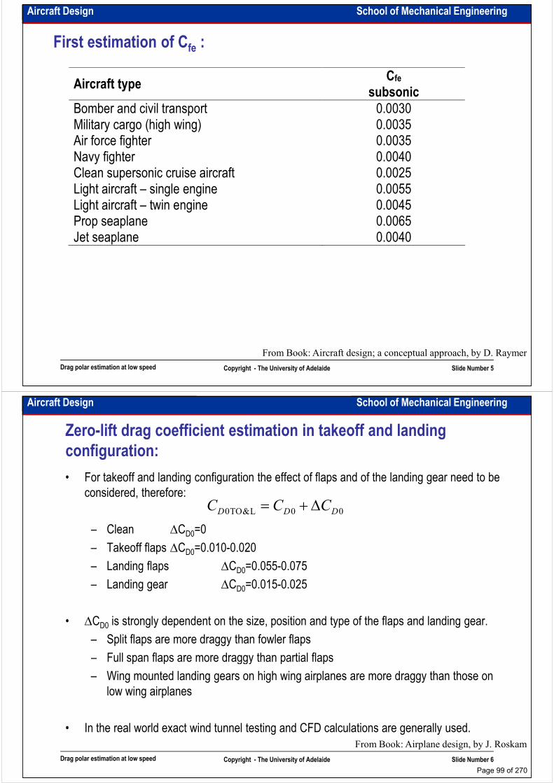
Aircraft Design School of Mechanical Engineering
First estimation of Cfe :
Aircraft type Cfe
subsonic
Bomber and civil transport Military cargo (high wing)
0.0030 0.0035 Military cargo (high wing)
Air force fighter Navy fighter Clean supersonic cruise aircraft Light aircraft – single engine Light aircraft – twin engine Prop seaplane Jet seaplane
0.0035 0.0035 0.0040 0.0025 0.0055 0.0045 0.0065 0.0040
Drag polar estimation at low speed Copyright - The University of Adelaide Slide Number 5
From Book: Aircraft design; a conceptual approach, by D. Raymer
Aircraft Design School of Mechanical Engineering
• For takeoff and landing configuration the effect of flaps and of the landing gear need to be
considered, therefore:
– Clean ∆C =0
Zero-lift drag coefficient estimation in takeoff and landing
configuration:
00L&TO0 DDD CCC ∆+=
– Clean ∆CD0=0
– Takeoff flaps ∆CD0=0.010-0.020
– Landing flaps ∆CD0=0.055-0.075
– Landing gear ∆CD0=0.015-0.025
• ∆CD0 is strongly dependent on the size, position and type of the flaps and landing gear.
– Split flaps are more draggy than fowler flaps
– Full span flaps are more draggy than partial flaps
Drag polar estimation at low speed Copyright - The University of Adelaide Slide Number 6
– Full span flaps are more draggy than partial flaps
– Wing mounted landing gears on high wing airplanes are more draggy than those on
low wing airplanes
• In the real world exact wind tunnel testing and CFD calculations are generally used.
From Book: Airplane design, by J. Roskam
Page 99 of 270
Aircraft Design School of Mechanical Engineering
Which aspect ratio is better?
• The best method is using the statistics (this is the method that we will use for the project)
• Maximum subsonic L/D of an aircraft increases approximately by the square root of an
increase in aspect ratio (because L/D mainly depends on SWET/SREF). It means: L/D∝A0.5.
On the other hand the more wing aspect ratio, the more wing weight by about the same On the other hand the more wing aspect ratio, the more wing weight by about the same
order. It means: Wwing∝A0.5.
• The less aspect ratio, the more stall angle of the wing (ref. aeronautical engineering). It
means: αstall∝A. This is one reason why tails to be of lower aspect ratio (to stall later) and a
canard has very high aspect ratio (to stall before the wing).
• Aspect ratio is usually determined by a trade study in which the aerodynamic advantages of
Drag polar estimation at low speed Copyright - The University of Adelaide Slide Number 7
• Aspect ratio is usually determined by a trade study in which the aerodynamic advantages of
a high aspect ratio are balanced against the increased weight.
Aircraft Design School of Mechanical Engineering
Intentionally left blank for your notes
………………………………………………………………………………………………
………………………………………………………………………………………………
………………………………………………………………………………………………
………………………………………………………………………………………………………………………………………………………………………………………………
………………………………………………………………………………………………
………………………………………………………………………………………………
………………………………………………………………………………………………
………………………………………………………………………………………………
………………………………………………………………………………………………
………………………………………………………………………………………………
………………………………………………………………………………………………
………………………………………………………………………………………………
………………………………………………………………………………………………
Drag polar estimation at low speed Copyright - The University of Adelaide Slide Number 8
………………………………………………………………………………………………
………………………………………………………………………………………………
………………………………………………………………………………………………
………………………………………………………………………………………………
………………………………………………………………………………………………
………………………………………………………………………………………….
Page 100 of 270

Aircraft Design School of Mechanical Engineering
Oswald efficiency factor estimation:
• For very rough calculation we can use the following data:
– Clean e=0.80-0.85
– Takeoff flaps e=0.75-0.80
– Landing flaps e=0.70-0.75
– Landing gear no effect
• For more realistic estimation equations based upon actual aircraft are presented below:
( )( ) ( )
°>Λ
−Λ⋅−=
−−=
30
1.3cos045.0161.4
64.0045.0178.1
15.068.0
68.0
LE
LEAe
Ae
: where
:aircraft wing-swept
:aircraft wing-straight
Drag polar estimation at low speed Copyright - The University of Adelaide Slide Number 9
– In these equations if wing has end-plates or winglets, the effective aspect ratio should be used
( )AA
bhAA
effective
effective
2.1
9.11
=
=+=
:winglet
height plate-endh where, :plate-end
From Book: Aircraft design; a conceptual approach, by D. Raymer
Aircraft Design School of Mechanical Engineering
More precise method – component buildup method:
• This method is not applicable for supersonic and transonic flight.
• In this method we use “flat-plate skin friction drag coefficient (Cf)”, “form factor (FF)”
and “interference factor(Q)”.
• In the following equation, subscript “c” indicates that related values are different for • In the following equation, subscript “c” indicates that related values are different for
each component, CDmisc is miscellaneous drags for special features such as flaps,
landing gears and so on, CDL&P is drag due to leakage and protuberances.
( )( )
PDLDmisc
ref
wetcccfc
subsonicD CCS
SQFFCC &0 ++
Σ=
Drag polar estimation at low speed Copyright - The University of Adelaide Slide Number 10
Page 101 of 270
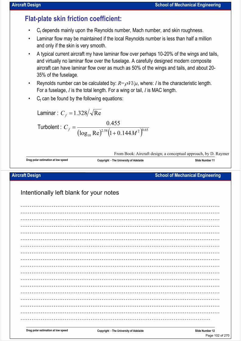
Aircraft Design School of Mechanical Engineering
Flat-plate skin friction coefficient:
• Cf depends mainly upon the Reynolds number, Mach number, and skin roughness.
• Laminar flow may be maintained if the local Reynolds number is less than half a million
and only if the skin is very smooth.
• A typical current aircraft my have laminar flow over perhaps 10-20% of the wings and tails,
and virtually no laminar flow over the fuselage. A carefully designed modern composite
aircraft can have laminar flow over as much as 50% of the wings and tails, and about 20-
35% of the fuselage.
• Reynolds number can be calculated by: R=ρVl/µ, where: l is the characteristic length. For a fuselage, l is the total length. For a wing or tail, l is MAC length.
• Cf can be found by the following equations:
Re328.1C = :Laminar
Drag polar estimation at low speed Copyright - The University of Adelaide Slide Number 11
( ) ( ) 65.0258.2
10 144.01Relog
455.0
Re328.1
MC
C
f
f
+=
=
:Turbolent
:Laminar
From Book: Aircraft design; a conceptual approach, by D. Raymer
Aircraft Design School of Mechanical Engineering
Intentionally left blank for your notes
………………………………………………………………………………………………
………………………………………………………………………………………………
………………………………………………………………………………………………
………………………………………………………………………………………………………………………………………………………………………………………………
………………………………………………………………………………………………
………………………………………………………………………………………………
………………………………………………………………………………………………
………………………………………………………………………………………………
………………………………………………………………………………………………
………………………………………………………………………………………………
………………………………………………………………………………………………
………………………………………………………………………………………………
………………………………………………………………………………………………
Drag polar estimation at low speed Copyright - The University of Adelaide Slide Number 12
………………………………………………………………………………………………
………………………………………………………………………………………………
………………………………………………………………………………………………
………………………………………………………………………………………………
………………………………………………………………………………………………
………………………………………………………………………………………….
Page 102 of 270
Aircraft Design School of Mechanical Engineering
Component form factors:
Component form factors estimate the pressure drag due to viscous separation. For more detail
see Aircraft design; a conceptual approach, by D. Raymer
( )( )28.0
46.0 tt
:pylon andstrut tail, Wing,
( )( )( )
( )
( )3
28.018.0
4400
601
cos34.11006.0
1
A
l
d
lf
f
fFF
cx
Mc
t
c
t
cxFF
m
m
m
m
π==
++=
Λ
Λ
+
+=
where,
:canopy smooth and Fuselage
line. thickness maximum the of sweep the to refers
andpoint thickness maximum airfoil the of location chordwise the is :here w
Drag polar estimation at low speed Copyright - The University of Adelaide Slide Number 13
( )
( ) max
max
4
35.01
4400
A
l
d
lf
fFF
Adf
π
π
==+=
where,
:store external smooth and Nacelle
From Book: Aircraft design; a conceptual approach, by D. Raymer
Aircraft Design School of Mechanical Engineering
Miscellaneous drags:
• The drag of miscellaneous items are usually determined experimentally
• The landing drag is estimated by using “drag area (D/q)”. To calculate CDLG we use the following table and equation:
)(Ft area Frontal 2
qD qD
)(Ft area Frontal 2
Regular wheel and tire Second wheel and tire in tandem Streamlined wheel and tire Wheel and tire with fairing Streamlined strut (1/6<t/c<1/3) Round strut or wire Flat spring gear leg Fork, bogey, irregular fitting
0.25 0.15 0.18 0.13 0.05 0.30 1.40
1.0-1.4
( )ref
fron
LGDA
A
qD
C
=
Drag polar estimation at low speed Copyright - The University of Adelaide Slide Number 14
From Book: Aircraft design; a conceptual approach, by D. Raymer
• For very rough estimation of flap contribution to parasite drag we can use the following equation (δflap in deg.)
Fork, bogey, irregular fitting 1.0-1.4
( ) flapflapDC δ⋅⋅=span wing
span flap0023.0
Page 103 of 270

Aircraft Design School of Mechanical Engineering
Leakage and protuberance drag:
• Leakage drag is due to the tendency of an aircraft to “inhale” through hols and gaps in high
pressure zone and exhale into the low pressure zone. The momentum loss of the inhaled air
contributes directly to drag and the air exhaled tends to produce additional airflow
separation.
• Protuberances include antennas, lights, and manufacturing defects like rivets or misaligned • Protuberances include antennas, lights, and manufacturing defects like rivets or misaligned
skin panels.
• For a normal production aircraft , leaks and protuberance drags can be estimated as about
2-5% of the parasite drag for jet transports or bombers, 5-10% for propeller aircraft, 4th and
5th generation fighters and 10-15% for other fighters.
• If special care is taken these drags can be reduced to near zero.
Drag polar estimation at low speed Copyright - The University of Adelaide Slide Number 15
From Book: Aircraft design; a conceptual approach, by D. Raymer
Aircraft Design School of Mechanical Engineering
Intentionally left blank for your notes
………………………………………………………………………………………………
………………………………………………………………………………………………
………………………………………………………………………………………………
………………………………………………………………………………………………………………………………………………………………………………………………
………………………………………………………………………………………………
………………………………………………………………………………………………
………………………………………………………………………………………………
………………………………………………………………………………………………
………………………………………………………………………………………………
………………………………………………………………………………………………
………………………………………………………………………………………………
………………………………………………………………………………………………
………………………………………………………………………………………………
Drag polar estimation at low speed Copyright - The University of Adelaide Slide Number 16
………………………………………………………………………………………………
………………………………………………………………………………………………
………………………………………………………………………………………………
………………………………………………………………………………………………
………………………………………………………………………………………………
………………………………………………………………………………………….
Page 104 of 270

School of Mechanical EngineeringAircraft Design
Sizing to FAR23 climb requirements
Dr. MAZIAR ARJOMANDI
Semester I
Sizing to FAR23 climb requirements Copyright - The University of Adelaide Slide Number 1
Semester I
Aircraft Design School of Mechanical Engineering
Climb general equation:• Rate of climb (RC) is a vertical velocity
• Climb gradient (G) is the ratio between vertical and horizontal distance travelled or:
G=Y/X=VY/VX=(dh/dt)/V
• If γ≅sin(γ) (γ is climb angle) then we have (for more detail see “Aeronautical Engineering I”):
( ) TDDT−=
−= , :or , ( )
( )
qCS
WG
W
T
S
W
Aeq
AeqS
W
S
W
qC
W
AeqS
qSC
S
W
qCAe
CqSqSC
W
D
GW
T
W
D
W
DTG
D
D
L
D
LD
π
π
ππ
0
2
0
2
0
2
0
01
1
=+
−−
+
=
+
=
+
=
−=−
=
:loading wingfor equation this solve can We
W :hence
, :or ,
Sizing to FAR23 climb requirements Copyright - The University of Adelaide Slide Number 2
Ae
CG
W
T
Aeq
Ae
CG
W
TG
W
T
S
W
SWSAeq
D
D
ππ
π
π
0
0
2
22
4
+≥
−
−±
−
=
: where, :have weThen
It means that for all aircraft thrust loading
must be greater than climb gradient
Page 105 of 270

Aircraft Design School of Mechanical Engineering
FAR23 climb requirements (FAR23.65):
• FAR23.65 (AEO – All Engines Operating) – takeoff climb requirements
– Minimum rate of climb – more than 300fpm (RC≥300fpm) at sea level
– Minimum climb gradient – more than 1/12rad for landplanes (CGR≥1/12rad)
and 1/15rad for seaplanes (CGR≥1/15rad) at sea level and 1/15rad for seaplanes (CGR≥1/15rad) at sea level
– Configuration - landing gears retracted, flaps in the takeoff position and
maximum continuous power on all engines
– If turbine powered airplanes – minimum steady climb gradient more than 4% at
a pressure altitude of 5000ft and at 81°F.
Sizing to FAR23 climb requirements Copyright - The University of Adelaide Slide Number 3
Aircraft Design School of Mechanical Engineering
FAR23 climb requirements (FAR23.67):
• FAR23.67 (OEI – One Engine Inoperative) – takeoff climb requirements for multiengine aircraft
– Minimum rate of climb – more than 0.027VS2fpm (VS in knots) at an altitude of
5000ft
– Configuration – one engine inoperative and its propeller in the minimum drag – Configuration – one engine inoperative and its propeller in the minimum drag configuration, takeoff power on operating engines, landing gears retracted and flaps in the most favourable position
– For more precise calculations see FAR manuals as above requirements are different for different weights (http://www.airweb.faa.gov)
– For turbine powered aircraft in abovementioned configuration:
• CGR≥1.2% or RC ≥0.027VS2fpm at 5000ft, standard atmosphere,
whichever is most critical
Sizing to FAR23 climb requirements Copyright - The University of Adelaide Slide Number 4
• CGR≥0.6% or RC ≥0.014VS2fpm at 5000ft and 81°F, whichever is most
critical
Page 106 of 270
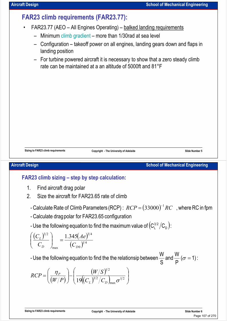
Aircraft Design School of Mechanical Engineering
FAR23 climb requirements (FAR23.77):
• FAR23.77 (AEO – All Engines Operating) – balked landing requirements
– Minimum climb gradient – more than 1/30rad at sea level
– Configuration – takeoff power on all engines, landing gears down and flaps in
landing positionlanding position
– For turbine powered aircraft it is necessary to show that a zero steady climb
rate can be maintained at a an altitude of 5000ft and 81°F
Sizing to FAR23 climb requirements Copyright - The University of Adelaide Slide Number 5
Aircraft Design School of Mechanical Engineering
FAR23 climb sizing – step by step calculation:
1. Find aircraft drag polar
2. Size the aircraft for FAR23.65 rate of climb
( )= −133000 RCRCP
ionconfigurat FAR23.65 for polar drag Calculate -
fpm in RC where, :(RCP) Parameters Climb of Rate Calculate -
( )( ) ( )
( )
( )
=
=
41
0
43
max
23
345.1
σ
DD
L
C
Ae
C
C
: 1)( P
W and
S
W between prelationsi the the find to equation following the Use -
:CC of value maximum the find to equation following the Use -
ionconfigurat FAR23.65 for polar drag Calculate -
D
23
L
Sizing to FAR23 climb requirements Copyright - The University of Adelaide Slide Number 6
( )( )
( )( )
−
=
21
max
23
21
19 ση
DL
P
CC
SW
PWRCP
Page 107 of 270

Aircraft Design School of Mechanical Engineering
FAR23 climb sizing – step by step calculation:
3. Size the aircraft for FAR23.67 rate of climb
( )ion)configurat previous from differs CD0 ionconfigurat this inthat attention(pay
:CC of value maximum the find to equation following the Use -
ionconfigurat FAR23.67 for polar drag Calculate -
D
23
L
( ) ( )( )
( )( )
( )( ) =
−
=
=
21
41
0
43
max
23
345.1
P
DD
L
SWRCP
C
Ae
C
C
ση
ratiodensity is 0.8617 here ,
: P
W and
S
W between prelationsi the find to equation following the Use -
ion)configurat previous from differs CD0 ionconfigurat this inthat attention(pay
Sizing to FAR23 climb requirements Copyright - The University of Adelaide Slide Number 7
( )( )
( )( )
==
=
−
=
max
2
min
21
max
23
2027.0
19
L
SS
DL
P
CS
WVVRC
CCPWRCP
ρ
σσ
and :that Consider
loadings. wingdifferent for RCP Calculate-
ratiodensity is 0.8617 here ,
Aircraft Design School of Mechanical Engineering
Intentionally left blank for your notes
………………………………………………………………………………………………
………………………………………………………………………………………………
………………………………………………………………………………………………
………………………………………………………………………………………………………………………………………………………………………………………………
………………………………………………………………………………………………
………………………………………………………………………………………………
………………………………………………………………………………………………
………………………………………………………………………………………………
………………………………………………………………………………………………
………………………………………………………………………………………………
………………………………………………………………………………………………
………………………………………………………………………………………………
………………………………………………………………………………………………
Sizing to FAR23 climb requirements Copyright - The University of Adelaide Slide Number 8
………………………………………………………………………………………………
………………………………………………………………………………………………
………………………………………………………………………………………………
………………………………………………………………………………………………
………………………………………………………………………………………………
………………………………………………………………………………………….
Page 108 of 270
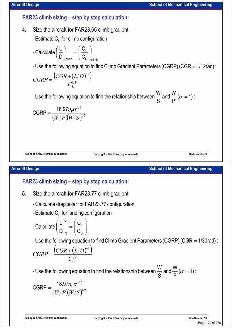
Aircraft Design School of Mechanical Engineering
FAR23 climb sizing – step by step calculation:
4. Size the aircraft for FAR23.65 climb gradient
L
L
C
C
D
L Calculate -
ionconfigurat climb for C Estimate -
=
( )( )
21
21
1
C
DLCGRCGRP
L
ση
σ
climbDclimb
18.97
:1)( P
W and
S
W between iprelationsh the find to equation following the Use -
:1/12rad)(CGR (CGRP) ParametersGradient Climb find to equation following the Use -
CD Calculate -
=
+=
=
=
−
Sizing to FAR23 climb requirements Copyright - The University of Adelaide Slide Number 9
( )( ) 2121
SWPW
σηP18.97CGRP =
Aircraft Design School of Mechanical Engineering
FAR23 climb sizing – step by step calculation:
5. Size the aircraft for FAR23.77 climb gradient
L ionconfigurat landing for C Estimate -
ionconfigurat FAR23.77 for polar drag Calculate -
( )( )21
1
C
DLCGRCGRP
L
σ
LD
L
L
:1)(P
W and
S
W between iprelationsh the find to equation following the Use -
:1/30rad)(CGR (CGRP) ParametersGradient Climb find to equation following the Use -
C
C
D
L Calculate -
=
+=
=
=
−
Sizing to FAR23 climb requirements Copyright - The University of Adelaide Slide Number 10
( )( ) 2121
SWPW
ση
σ
P18.97CGRP
:1)(P
and S
between iprelationsh the find to equation following the Use -
=
=
Page 109 of 270
Aircraft Design School of Mechanical Engineering
Example:
• Size a well-designed full composite twin-engine propeller aircraft with a takeoff
weight of 5200lb and landing weight of 5200lb to the FAR23 climb requirements
Sizing to FAR23 climb requirements Copyright - The University of Adelaide Slide Number 11
Aircraft Design School of Mechanical Engineering
Intentionally left blank for your notes
………………………………………………………………………………………………
………………………………………………………………………………………………
………………………………………………………………………………………………
………………………………………………………………………………………………………………………………………………………………………………………………
………………………………………………………………………………………………
………………………………………………………………………………………………
………………………………………………………………………………………………
………………………………………………………………………………………………
………………………………………………………………………………………………
………………………………………………………………………………………………
………………………………………………………………………………………………
………………………………………………………………………………………………
………………………………………………………………………………………………
Sizing to FAR23 climb requirements Copyright - The University of Adelaide Slide Number 12
………………………………………………………………………………………………
………………………………………………………………………………………………
………………………………………………………………………………………………
………………………………………………………………………………………………
………………………………………………………………………………………………
………………………………………………………………………………………….
Page 110 of 270
School of Mechanical EngineeringAircraft Design
Sizing to FAR25 climb requirements
Dr. MAZIAR ARJOMANDI
Semester I
Sizing to FAR25 climb requirements Copyright - The University of Adelaide Slide Number 1
Semester I
Aircraft Design School of Mechanical Engineering
FAR25 climb requirements (FAR25.111):
• FAR25.111 (OEI – One Engine Inoperative) – initial climb segment requirements
– Minimum climb gradient with the critical engine inoperative must be more than:
• 1.2% for two-engine aircraft
• 1.5% for three-engine aircraft
• 1.7% for four engine aircraft
– Configuration:
• Landing gears retracted
• Flaps in the takeoff position
• Takeoff thrust or power on remaining engines
• Speed is V2=1.2VS
• Ground effect must be accounted
Sizing to FAR25 climb requirements Copyright - The University of Adelaide Slide Number 2
• Ground effect must be accounted
• Maximum takeoff weight
• Sea level at t=50°F and 34% humidity
Page 111 of 270
Aircraft Design School of Mechanical Engineering
FAR25 climb requirements (FAR25.121):
• FAR25.121 (OEI – One Engine Inoperative) – transition segment climb requirements
– Minimum climb gradient with the critical engine inoperative must be more than:
• 0% for two-engine aircraft
• 0.3% for three-engine aircraft
• 0.5% for four engine aircraft
– Configuration:
• Landing gears down
• Flaps in the takeoff position
• Takeoff thrust or power on remaining engines
• Speed is between VLOF≅1.1VS and V2=1.2VS• Ground effect must be accounted
Sizing to FAR25 climb requirements Copyright - The University of Adelaide Slide Number 3
• Ground effect must be accounted
• Maximum takeoff weight
• Sea level at t=50°F and 34% humidity
Aircraft Design School of Mechanical Engineering
FAR25 climb requirements (FAR25.121):
• FAR25.121 (OEI – One Engine Inoperative) – second segment climb requirements
– Minimum climb gradient with the critical engine inoperative must be more than:
• 2.4% for two-engine aircraft
• 2.7% for three-engine aircraft
• 3.0% for four engine aircraft
– Configuration:
• Landing gears retracted
• Flaps in the takeoff position
• Takeoff thrust or power on remaining engines
• Speed is at V2=1.2VS
• No ground effect
Sizing to FAR25 climb requirements Copyright - The University of Adelaide Slide Number 4
• No ground effect
• Maximum takeoff weight
• Sea level at t=50°F and 34% humidity
Page 112 of 270

Aircraft Design School of Mechanical Engineering
FAR25 climb requirements (FAR25.121):
• FAR25.121 (OEI – One Engine Inoperative) – en-route climb requirements
– Minimum climb gradient with the critical engine inoperative must be more than:
• 1.2% for two-engine aircraft
• 1.5% for three-engine aircraft
• 1.7% for four engine aircraft
– Configuration:
• Landing gears retracted
• Flaps retracted
• Maximum continuous thrust or power on remaining engines
• Speed is at 1.25VS
• No ground effect, en-route climb altitude
Sizing to FAR25 climb requirements Copyright - The University of Adelaide Slide Number 5
• No ground effect, en-route climb altitude
• Maximum takeoff weight
• Sea level at t=50°F and 34% humidity
Aircraft Design School of Mechanical Engineering
FAR25 climb requirements (FAR25.119):
• FAR25.119 (AEO – All Engines Operating) – landing climb – balk landing requirements
– Minimum climb gradient must be more than 3.2%
– Configuration:
• Landing gears down
• Flaps in the landing position
• Takeoff thrust or power on all engines
• Speed is at 1.3VSL
• Maximum design landing weight
• Sea level at t=50°F and 34% humidity
Sizing to FAR25 climb requirements Copyright - The University of Adelaide Slide Number 6
Page 113 of 270
Aircraft Design School of Mechanical Engineering
FAR25 climb requirements (FAR25.121):
• FAR25.121 (OEI – One Engine Inoperative) – landing climb – balk landing
requirements
– Minimum climb gradient with the critical engine inoperative must be more than:
• 2.1% for two-engine aircraft
• 2.4% for three-engine aircraft• 2.4% for three-engine aircraft
• 2.7% for four engine aircraft
– Configuration:
• Landing gears down
• Flaps in the approach position
• Takeoff thrust or power on remaining engines
• Speed is at 1.5VSA
• Maximum design landing weight
Sizing to FAR25 climb requirements Copyright - The University of Adelaide Slide Number 7
• Maximum design landing weight
• Sea level at t=50°F and 34% humidity
Aircraft Design School of Mechanical Engineering
FAR25 climb sizing – step by step calculation:
1. Find aircraft drag polar
2. Calculate L/D for each configuration
3. For propeller driven aircraft use the equations discussed on the previous lecture
4. For jet powered aircraft use the following equations. As it is seen in these equations, 4. For jet powered aircraft use the following equations. As it is seen in these equations,
FAR25 climb requirements are a function of T/W and FAR23 climb requirements are
a function of T/W and W/S
( )( )
( )( )T
CGRDLN
N
W
T+
−
= −1
1
: AEOFor
:OEI For
Sizing to FAR25 climb requirements Copyright - The University of Adelaide Slide Number 8
( )( )CGRDLW
T+= −1
Page 114 of 270

Aircraft Design School of Mechanical Engineering
Example:
• Size a three-engine jet transport with a takeoff weight of 185000lb and landing
weight of 154000lb to the FAR25 climb requirements
Sizing to FAR25 climb requirements Copyright - The University of Adelaide Slide Number 9
Aircraft Design School of Mechanical Engineering
Intentionally left blank for your notes
………………………………………………………………………………………………
………………………………………………………………………………………………
………………………………………………………………………………………………
………………………………………………………………………………………………………………………………………………………………………………………………
………………………………………………………………………………………………
………………………………………………………………………………………………
………………………………………………………………………………………………
………………………………………………………………………………………………
………………………………………………………………………………………………
………………………………………………………………………………………………
………………………………………………………………………………………………
………………………………………………………………………………………………
………………………………………………………………………………………………
Sizing to FAR25 climb requirements Copyright - The University of Adelaide Slide Number 10
………………………………………………………………………………………………
………………………………………………………………………………………………
………………………………………………………………………………………………
………………………………………………………………………………………………
………………………………………………………………………………………………
………………………………………………………………………………………….
Page 115 of 270
School of Mechanical EngineeringAircraft Design
Sizing to time to climb, ceiling and manoeuvring Sizing to time to climb, ceiling and manoeuvring
requirements
Dr. MAZIAR ARJOMANDI
Semester I
Sizing to time to climb, ceiling and
manoeuvring requirements
Copyright - The University of Adelaide Slide Number 1
Semester I
Aircraft Design School of Mechanical Engineering
Sizing to time to climb requirements:
Time required to climb from one altitude h1 to
another altitude h2 can be determined by:
∫=2
1
h
h RC
dht
We assume that rate of climb decreases linearly
with altitude (for more detail see “Aeronautical
Engineering I – lecture notes”) then:
∫1h RC
−=
absh
hRCRC 10
Sizing to time to climb, ceiling and
manoeuvring requirementsCopyright - The University of Adelaide Slide Number 2
And if we solve the integral:RC0 is RC at sea level
RC is RC at altitude h
From Book: Airplane design, by J. Roskam
absh
−=
abs
abs
hht
hRC
1
1ln0
Page 116 of 270
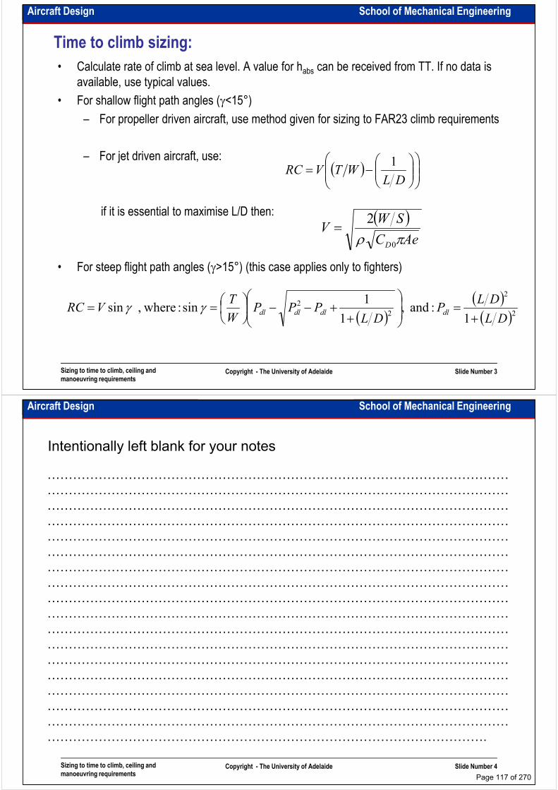
Aircraft Design School of Mechanical Engineering
Time to climb sizing:
• Calculate rate of climb at sea level. A value for habs can be received from TT. If no data is
available, use typical values.
• For shallow flight path angles (γ<15°)
– For propeller driven aircraft, use method given for sizing to FAR23 climb requirements
– For jet driven aircraft, use:
if it is essential to maximise L/D then:
• For steep flight path angles (γ>15°) (this case applies only to fighters)
( )
−=
DLWTVRC
1
( )AeC
SWV
D πρ 0
2=
Sizing to time to climb, ceiling and
manoeuvring requirementsCopyright - The University of Adelaide Slide Number 3
• For steep flight path angles (γ>15°) (this case applies only to fighters)
( )( )( )2
2
2
2
1 :and ,
1
1sin : where, sin
DL
DLP
DLPPP
W
TVRC dldldldl
+=
++−−
== γγ
Aircraft Design School of Mechanical Engineering
Intentionally left blank for your notes
………………………………………………………………………………………………
………………………………………………………………………………………………
………………………………………………………………………………………………
………………………………………………………………………………………………………………………………………………………………………………………………
………………………………………………………………………………………………
………………………………………………………………………………………………
………………………………………………………………………………………………
………………………………………………………………………………………………
………………………………………………………………………………………………
………………………………………………………………………………………………
………………………………………………………………………………………………
………………………………………………………………………………………………
………………………………………………………………………………………………
Sizing to time to climb, ceiling and
manoeuvring requirementsCopyright - The University of Adelaide Slide Number 4
………………………………………………………………………………………………
………………………………………………………………………………………………
………………………………………………………………………………………………
………………………………………………………………………………………………
………………………………………………………………………………………………
………………………………………………………………………………………….
Page 117 of 270
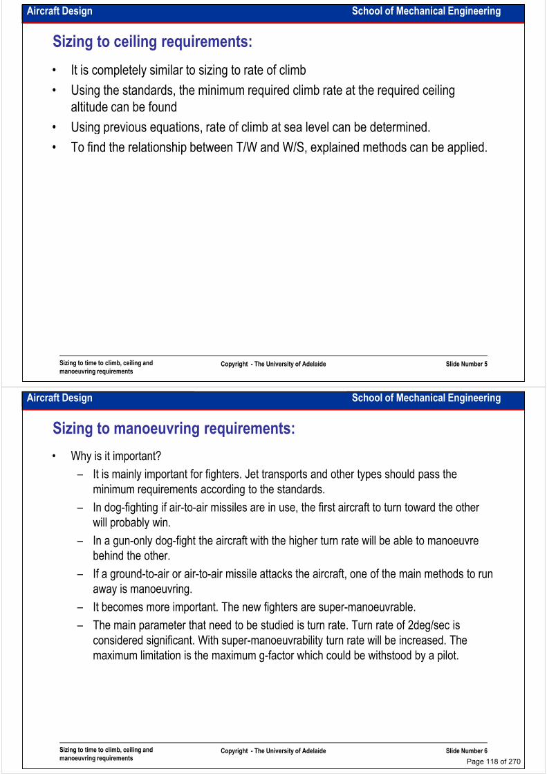
Aircraft Design School of Mechanical Engineering
Sizing to ceiling requirements:
• It is completely similar to sizing to rate of climb
• Using the standards, the minimum required climb rate at the required ceiling
altitude can be found
• Using previous equations, rate of climb at sea level can be determined.• Using previous equations, rate of climb at sea level can be determined.
• To find the relationship between T/W and W/S, explained methods can be applied.
Sizing to time to climb, ceiling and
manoeuvring requirementsCopyright - The University of Adelaide Slide Number 5
Aircraft Design School of Mechanical Engineering
Sizing to manoeuvring requirements:
• Why is it important?
– It is mainly important for fighters. Jet transports and other types should pass the
minimum requirements according to the standards.
– In dog-fighting if air-to-air missiles are in use, the first aircraft to turn toward the other
will probably win.will probably win.
– In a gun-only dog-fight the aircraft with the higher turn rate will be able to manoeuvre
behind the other.
– If a ground-to-air or air-to-air missile attacks the aircraft, one of the main methods to run
away is manoeuvring.
– It becomes more important. The new fighters are super-manoeuvrable.
– The main parameter that need to be studied is turn rate. Turn rate of 2deg/sec is
considered significant. With super-manoeuvrability turn rate will be increased. The
Sizing to time to climb, ceiling and
manoeuvring requirementsCopyright - The University of Adelaide Slide Number 6
considered significant. With super-manoeuvrability turn rate will be increased. The
maximum limitation is the maximum g-factor which could be withstood by a pilot.
Page 118 of 270
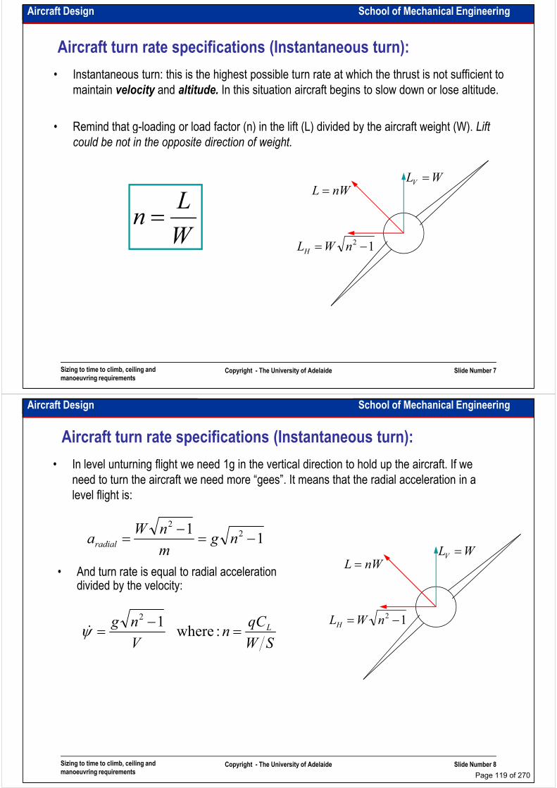
Aircraft Design School of Mechanical Engineering
Aircraft turn rate specifications (Instantaneous turn):
• Instantaneous turn: this is the highest possible turn rate at which the thrust is not sufficient to
maintain velocity and altitude. In this situation aircraft begins to slow down or lose altitude.
• Remind that g-loading or load factor (n) in the lift (L) divided by the aircraft weight (W). Lift • Remind that g-loading or load factor (n) in the lift (L) divided by the aircraft weight (W). Lift
could be not in the opposite direction of weight.
WLV =
12 −= nWLH
nWL =
W
Ln =
Sizing to time to climb, ceiling and
manoeuvring requirementsCopyright - The University of Adelaide Slide Number 7
Aircraft Design School of Mechanical Engineering
Aircraft turn rate specifications (Instantaneous turn):
• In level unturning flight we need 1g in the vertical direction to hold up the aircraft. If we
need to turn the aircraft we need more “gees”. It means that the radial acceleration in a
level flight is:
12 −nW
WLV =
12 −= nWLH
nWL =
11 2
2
−=−
= ngm
nWaradial
• And turn rate is equal to radial acceleration divided by the velocity:
SW
qCn
V
ng L=−
= : where12
ψɺ
Sizing to time to climb, ceiling and
manoeuvring requirementsCopyright - The University of Adelaide Slide Number 8
Page 119 of 270

Aircraft Design School of Mechanical Engineering
Aircraft turn rate specifications (Instantaneous turn):
• These two equations show:
SW
qCn
V
ng L=−
= : where12
ψɺ
• These two equations show:
• To increase turn rate we have to increase load factor
– To increase load factor we need more CL and less wing loading.
– Increasing the speed increases load factor but decreases turn rate!
• Corner speed is the speed at which the maximum lift available exactly equals the
allowable load factor and provides the maximum turn rate for the aircraft at a specific
altitude. Pilots try to get to corner speed in a dogfight as it provides the best turn rate.
• The maximum load factor is usually limited by human body tolerance and structural
Sizing to time to climb, ceiling and
manoeuvring requirementsCopyright - The University of Adelaide Slide Number 9
• The maximum load factor is usually limited by human body tolerance and structural
limit.
• The combat weight and lift coefficient are different from maximum weight and
maximum lift coefficient.
Aircraft Design School of Mechanical Engineering
Aircraft turn rate specifications (Sustained turn):
• Sustained turn: this is the turn rate at which the thrust is sufficient to maintain velocity and
altitude. In this situation the thrust must equal the drag and the lift must equal the load
factor times the weight.
• For sustained turn rate we have:
WLV =
12 −= nWLH
nWL =:or and DTLnW ==
=D
L
W
Tn
• To maximise n we need to maximise L/D. Recall
Sizing to time to climb, ceiling and
manoeuvring requirementsCopyright - The University of Adelaide Slide Number 10
• To maximise n we need to maximise L/D. Recall
“Aero I”: L/D is maximised when D=qs(2CD0) or
CD0=CDi. Then:
Page 120 of 270
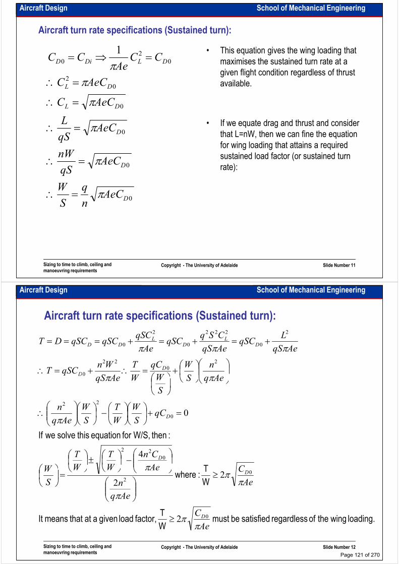
Aircraft Design School of Mechanical Engineering
Aircraft turn rate specifications (Sustained turn):
• This equation gives the wing loading that
maximises the sustained turn rate at a
given flight condition regardless of thrust
available.0
2
0
2
0
1
DL
DLDiD
AeCC
CCAe
CC
π
ππ
=∴
=∴
=⇒=
• If we equate drag and thrust and consider
that L=nW, then we can fine the equation
for wing loading that attains a required
sustained load factor (or sustained turn
rate):0
0
0
D
D
DL
qW
AeCqS
nW
AeCqS
L
AeCC
π
π
π
π
=∴
=∴
=∴
=∴
Sizing to time to climb, ceiling and
manoeuvring requirementsCopyright - The University of Adelaide Slide Number 11
0DAeCn
q
S
Wπ=∴
Aircraft Design School of Mechanical Engineering
Aircraft turn rate specifications (Sustained turn):
Aeq
n
S
W
W
qC
W
T
AeqS
WnqSCT
AeqS
LqSC
AeqS
CSqqSC
Ae
qSCqSCqSCDT
DD
DL
DL
DD
ππ
πππ2
0
22
0
2
0
222
0
2
0
+
=∴+=∴
+=+=+===
T
:then W/S, for equation this solve weIf
CAe
Cn
W
T
W
T
W
qCS
W
W
T
S
W
Aeq
n
AeqS
S
WWAeqS
D
D
D
ππ
π
ππ
0
22
0
22
0
4
0
≥
−
±
=
=+
−
∴
Sizing to time to climb, ceiling and
manoeuvring requirementsCopyright - The University of Adelaide Slide Number 12
loading. wingthe of regardless satisfied bemust W
T factor, load given aat that meansIt
W
T : where
Ae
C
Ae
C
Aeq
n
AeWW
S
W
D
D
ππ
ππ
π
π
0
0
2
2
22
≥
≥
=
Page 121 of 270
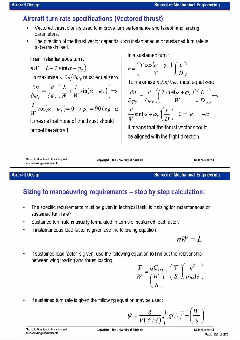
Aircraft Design School of Mechanical Engineering
Aircraft turn rate specifications (Vectored thrust):
• Vectored thrust often is used to improve turn performance and takeoff and landing parameters.
• The direction of the thrust vector depends upon instantaneous or sustained turn rate is to be maximised.
:turn ousinstantane an In:turn sustained a In
( )
( )
( )
zero. equalmust , maximise To
:turn ousinstantane an In
αϕϕα
ϕαϕϕ
ϕ
ϕα
−=⇒=+
⇒
++∂∂
=∂∂
∂∂
++=
deg900cos
sin
sin
TT
T
TT
T
T
W
T
W
T
W
Ln
nn
TLnW( )
( )
( )
zero. equalmust , maximise To
:turn sustained a In
αϕϕα
ϕαϕϕ
ϕ
ϕα
−=⇒=
+
⇒
+∂∂
=∂∂
∂∂
+=
T
TT
T
T
LT
D
L
W
Tn
nn
D
L
W
Tn
0sin
cos
cos
Sizing to time to climb, ceiling and
manoeuvring requirementsCopyright - The University of Adelaide Slide Number 13
aircraft. the propel
shouldthrust the of nonethat meansIt
TTW ( )
direction.flight the withaligned be
should vectorthrust thethat meansIt
αϕϕα −=⇒=
+ TTD
L
W
T0sin
Aircraft Design School of Mechanical Engineering
Sizing to manoeuvring requirements – step by step calculation:
• The specific requirements must be given in technical task: is it sizing for instantaneous or
sustained turn rate?
• Sustained turn rate is usually formulated in terms of sustained load factor.
• If instantaneous load factor is given use the following equation:• If instantaneous load factor is given use the following equation:
• If sustained load factor is given, use the following equation to find out the relationship
between wing loading and thrust loading.
LnW =
+
=Aeq
n
S
W
S
W
qC
W
T D
π
2
0
Sizing to time to climb, ceiling and
manoeuvring requirementsCopyright - The University of Adelaide Slide Number 14
• If sustained turn rate is given the following equation may be used:
S
( )( )
2
2
−=S
WqC
SWV
gLψɺ
Page 122 of 270
Aircraft Design School of Mechanical Engineering
Example:
• Size an F-16 for sustained load factor of 4.5g at sea level (configuration: aircraft
carries only AA missiles at 800km/h)
Sizing to time to climb, ceiling and
manoeuvring requirementsCopyright - The University of Adelaide Slide Number 15
Aircraft Design School of Mechanical Engineering
Intentionally left blank for your notes
………………………………………………………………………………………………
………………………………………………………………………………………………
………………………………………………………………………………………………
………………………………………………………………………………………………………………………………………………………………………………………………
………………………………………………………………………………………………
………………………………………………………………………………………………
………………………………………………………………………………………………
………………………………………………………………………………………………
………………………………………………………………………………………………
………………………………………………………………………………………………
………………………………………………………………………………………………
………………………………………………………………………………………………
………………………………………………………………………………………………
Sizing to time to climb, ceiling and
manoeuvring requirementsCopyright - The University of Adelaide Slide Number 16
………………………………………………………………………………………………
………………………………………………………………………………………………
………………………………………………………………………………………………
………………………………………………………………………………………………
………………………………………………………………………………………………
………………………………………………………………………………………….
Page 123 of 270

School of Mechanical EngineeringAircraft Design
Sizing to cruise speed requirements – matching Sizing to cruise speed requirements – matching
diagram
Dr. MAZIAR ARJOMANDI
Semester I
Sizing to cruise speed requirements –
matching diagram
Copyright - The University of Adelaide Slide Number 1
Semester I
Aircraft Design School of Mechanical Engineering
Sizing to cruise speed requirements (propeller driven aircraft):
• It is obvious that required power is a function of aircraft speed and in cruise D=T.
• In propeller driven aircraft usually we use 75% of maximum power for cruise. It could be
SCVSHPqSVCTVP DPDreq
3
2
1550 or, ρη =⋅⋅==
• In propeller driven aircraft usually we use 75% of maximum power for cruise. It could be calculated but we can assume that:
• It could be shown that (see “Aero I”):
• We can call IP the power index:
01.0 DDi CC =
( ) ( )3
0
//
DP C
PWSWV
ση∝
( ) ( )σ=
Sizing to cruise speed requirements –
matching diagramCopyright - The University of Adelaide Slide Number 2
• IP could be found from statistical data and using this equation we can find the relationship between wing loading and power loading
( ) ( )3 // PWSWIP σ=
Page 124 of 270

Aircraft Design School of Mechanical Engineering
Sizing to cruise speed requirements (jet aircraft):
qS
qSCWqSCDT LDreq
+=⇒+=
====
1
:then L and,
• Recall “Aero I”:
( )Aeq
SW
SW
qC
W
T
CAe
qSqSCTC
AeCC
D
LDLDD
π
ππ
+=∴
+=⇒+=
0
2
0
2
0
1
• Don’t forget that (W/S)TO=(WTO/W)(W/S)
• Don’t forget that if the aircraft cruise speed is more that 0.5M, the flow
Sizing to cruise speed requirements –
matching diagramCopyright - The University of Adelaide Slide Number 3
• Don’t forget that if the aircraft cruise speed is more that 0.5M, the flow
compressibility effect should be considered (recalculate CD0)
Aircraft Design School of Mechanical Engineering
Intentionally left blank for your notes
………………………………………………………………………………………………
………………………………………………………………………………………………
………………………………………………………………………………………………
………………………………………………………………………………………………………………………………………………………………………………………………
………………………………………………………………………………………………
………………………………………………………………………………………………
………………………………………………………………………………………………
………………………………………………………………………………………………
………………………………………………………………………………………………
………………………………………………………………………………………………
………………………………………………………………………………………………
………………………………………………………………………………………………
………………………………………………………………………………………………
Sizing to cruise speed requirements –
matching diagramCopyright - The University of Adelaide Slide Number 4
………………………………………………………………………………………………
………………………………………………………………………………………………
………………………………………………………………………………………………
………………………………………………………………………………………………
………………………………………………………………………………………………
………………………………………………………………………………………….
Page 125 of 270
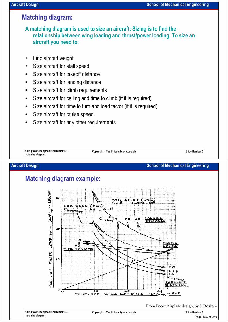
Aircraft Design School of Mechanical Engineering
Matching diagram:
A matching diagram is used to size an aircraft: Sizing is to find the relationship between wing loading and thrust/power loading. To size an aircraft you need to:
• Find aircraft weight
• Size aircraft for stall speed
• Size aircraft for takeoff distance
• Size aircraft for landing distance
• Size aircraft for climb requirements
• Size aircraft for ceiling and time to climb (if it is required)
• Size aircraft for time to turn and load factor (if it is required)
Sizing to cruise speed requirements –
matching diagramCopyright - The University of Adelaide Slide Number 5
• Size aircraft for time to turn and load factor (if it is required)
• Size aircraft for cruise speed
• Size aircraft for any other requirements
Aircraft Design School of Mechanical Engineering
Matching diagram example:
Sizing to cruise speed requirements –
matching diagramCopyright - The University of Adelaide Slide Number 6
From Book: Airplane design, by J. Roskam
Page 126 of 270

Aircraft Design School of Mechanical Engineering
Matching diagram example:
Sizing to cruise speed requirements –
matching diagramCopyright - The University of Adelaide Slide Number 7
From Book: Airplane design, by J. Roskam
Aircraft Design School of Mechanical Engineering
Intentionally left blank for your notes
………………………………………………………………………………………………
………………………………………………………………………………………………
………………………………………………………………………………………………
………………………………………………………………………………………………………………………………………………………………………………………………
………………………………………………………………………………………………
………………………………………………………………………………………………
………………………………………………………………………………………………
………………………………………………………………………………………………
………………………………………………………………………………………………
………………………………………………………………………………………………
………………………………………………………………………………………………
………………………………………………………………………………………………
………………………………………………………………………………………………
Sizing to cruise speed requirements –
matching diagramCopyright - The University of Adelaide Slide Number 8
………………………………………………………………………………………………
………………………………………………………………………………………………
………………………………………………………………………………………………
………………………………………………………………………………………………
………………………………………………………………………………………………
………………………………………………………………………………………….
Page 127 of 270

Aircraft Design School of Mechanical Engineering
Matching diagram example:
Sizing to cruise speed requirements –
matching diagramCopyright - The University of Adelaide Slide Number 9
From Book: Airplane design, by J. Roskam
Aircraft Design School of Mechanical Engineering
Matching diagram example:
Sizing to cruise speed requirements –
matching diagramCopyright - The University of Adelaide Slide Number 10
From: www.darcorp.com
Page 128 of 270
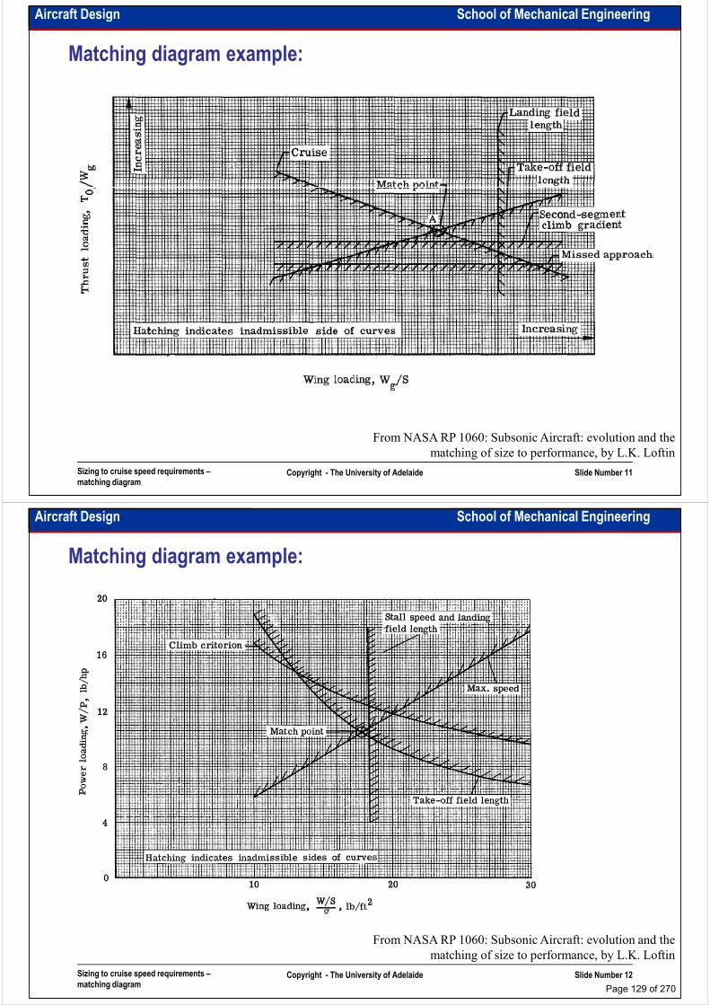
Aircraft Design School of Mechanical Engineering
Matching diagram example:
Sizing to cruise speed requirements –
matching diagramCopyright - The University of Adelaide Slide Number 11
From NASA RP 1060: Subsonic Aircraft: evolution and the
matching of size to performance, by L.K. Loftin
Aircraft Design School of Mechanical Engineering
Matching diagram example:
Sizing to cruise speed requirements –
matching diagramCopyright - The University of Adelaide Slide Number 12
From NASA RP 1060: Subsonic Aircraft: evolution and the
matching of size to performance, by L.K. Loftin
Page 129 of 270
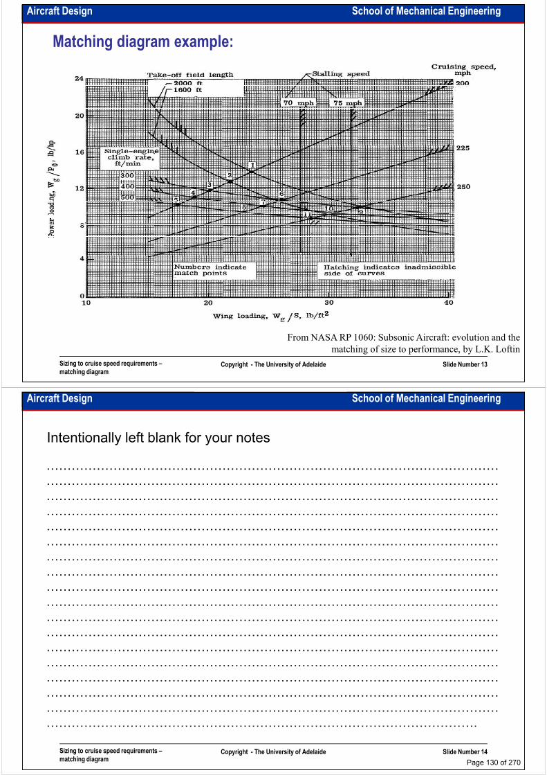
Aircraft Design School of Mechanical Engineering
Matching diagram example:
Sizing to cruise speed requirements –
matching diagramCopyright - The University of Adelaide Slide Number 13
From NASA RP 1060: Subsonic Aircraft: evolution and the
matching of size to performance, by L.K. Loftin
Aircraft Design School of Mechanical Engineering
Intentionally left blank for your notes
………………………………………………………………………………………………
………………………………………………………………………………………………
………………………………………………………………………………………………
………………………………………………………………………………………………………………………………………………………………………………………………
………………………………………………………………………………………………
………………………………………………………………………………………………
………………………………………………………………………………………………
………………………………………………………………………………………………
………………………………………………………………………………………………
………………………………………………………………………………………………
………………………………………………………………………………………………
………………………………………………………………………………………………
………………………………………………………………………………………………
Sizing to cruise speed requirements –
matching diagramCopyright - The University of Adelaide Slide Number 14
………………………………………………………………………………………………
………………………………………………………………………………………………
………………………………………………………………………………………………
………………………………………………………………………………………………
………………………………………………………………………………………………
………………………………………………………………………………………….
Page 130 of 270

Aircraft Design School of Mechanical Engineering
Matching diagram example:
Sizing to cruise speed requirements –
matching diagramCopyright - The University of Adelaide Slide Number 15
From Design and build of a UAV with morphing configuration by Kevin Chan,
Crystal Forrester, Ian Lomas, Simon Mitchell, Carlee Stacey
Aircraft Design School of Mechanical Engineering
Multiobjective Multidisciplinary Optimisation Methods for takeoff
weight estimation:
• If we generate the mathematical model of the aircraft we can find the relationship
between the main performance parameters and aircraft takeoff weight. In other
words, we know that: words, we know that:
1. Takeoff and landing distance, cruise speed, ceiling, rate of climb and climb
angle and … are the function of WING LOADING AND THRUST/POWER
LOADING.
2. Aircraft takeoff weight also is a function of WING LOADING AND
THRUST/POWER LOADING.
– Then we can find a relationship between PERFORMANCE PARAMETERS and
TAKEOFF WEIGHT.
Sizing to cruise speed requirements –
matching diagramCopyright - The University of Adelaide Slide Number 16
TAKEOFF WEIGHT.
– These methods usually are based on statistical analysis and mathematical
modelling
Page 131 of 270

Aircraft Design School of Mechanical Engineering
Example: Jet transports takeoff weight estimation
( ) ( )
: where, W
:equation following theby estimated be can weight takeoff transport,jet a For
TO +
−+
=F
F bL
La
1
1ln
2
2
( ) ( )( ) ( )
( )( )
T in weight takeoff is and m in distances landing and takeoff are and
T, in weight payload the is seats, of number the is km, in range is :Here
+=
+=
+×−+⋅+×=
×+−⋅×+−=−−
Ps
LTOF
PS
WLL
WnR
LLL
Wnn
RnRb
RnRRa
5.0
105.0
594.0104.823.01094.3
105.11141002.201.100306.0
55
542
Sizing to cruise speed requirements –
matching diagramCopyright - The University of Adelaide Slide Number 17
analysis sesitivity for usedy effectivel be canIt
10% than morenot are errors ncalculatio The
T in weight takeoff is and m in distances landing and takeoff are and
◊
◊TOLTO WLL
From Journal of Aircraft Design: A simplified method for
estimation the takeoff weight, by M. Arjomandi
Aircraft Design School of Mechanical Engineering
Example: a one piston engine full composite aircraft
• A one piston engine full composite aircraft is given. Size this aircraft for:
– 4 passengers at 175lb each and 40kg additional baggage
– 1000km range at h=10000ft
– 160knots cruise speed– 160knots cruise speed
– 1500ft takeoff distance at SL and ISA
– 2500ft landing distance at SL and ISA
– Good one-slotted fowler flap
Sizing to cruise speed requirements –
matching diagramCopyright - The University of Adelaide Slide Number 18
Page 132 of 270
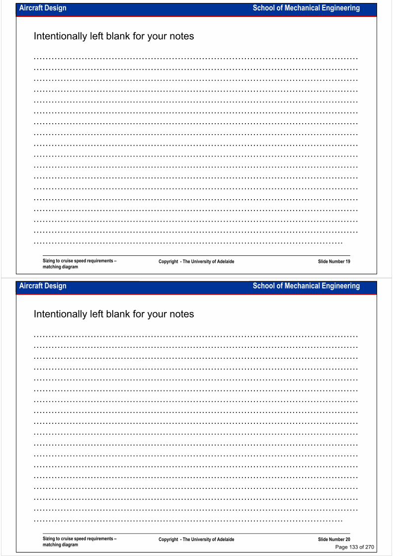
Aircraft Design School of Mechanical Engineering
Intentionally left blank for your notes
………………………………………………………………………………………………
………………………………………………………………………………………………
………………………………………………………………………………………………
………………………………………………………………………………………………………………………………………………………………………………………………
………………………………………………………………………………………………
………………………………………………………………………………………………
………………………………………………………………………………………………
………………………………………………………………………………………………
………………………………………………………………………………………………
………………………………………………………………………………………………
………………………………………………………………………………………………
………………………………………………………………………………………………
………………………………………………………………………………………………
Sizing to cruise speed requirements –
matching diagramCopyright - The University of Adelaide Slide Number 19
………………………………………………………………………………………………
………………………………………………………………………………………………
………………………………………………………………………………………………
………………………………………………………………………………………………
………………………………………………………………………………………………
………………………………………………………………………………………….
Aircraft Design School of Mechanical Engineering
Intentionally left blank for your notes
………………………………………………………………………………………………
………………………………………………………………………………………………
………………………………………………………………………………………………
………………………………………………………………………………………………………………………………………………………………………………………………
………………………………………………………………………………………………
………………………………………………………………………………………………
………………………………………………………………………………………………
………………………………………………………………………………………………
………………………………………………………………………………………………
………………………………………………………………………………………………
………………………………………………………………………………………………
………………………………………………………………………………………………
………………………………………………………………………………………………
Sizing to cruise speed requirements –
matching diagramCopyright - The University of Adelaide Slide Number 20
………………………………………………………………………………………………
………………………………………………………………………………………………
………………………………………………………………………………………………
………………………………………………………………………………………………
………………………………………………………………………………………………
………………………………………………………………………………………….
Page 133 of 270
Aircraft Design School of Mechanical Engineering
Example: 2008 exam
A jet transport has the following mission specification:
• Payload: 150 passengers at 80kg each and 25kg of baggage each.
• Crew: Two pilots and 6 cabin attendants at 75kg each and 15kg of baggage each.
• Range: 4,000km. Reserve for flight to an alternate airport at 250km.
• Altitude: 11,200m. Flight to alternate airport is at an altitude of 5,500m.• Altitude: 11,200m. Flight to alternate airport is at an altitude of 5,500m.
• Cruise speed: M=0.87.
• Climb: Climb to cruise altitude in 20min.
• Descent: Descent from cruise altitude in 10min.
• Takeoff and landing: FAR25 field length 5,500ft at an altitude of 5,000ft and a 95°F day. Assume that WL=0.85WTO.
• Power plants: Two turbofans.
• Configuration: Low-wing, triple-slotted Fowler flap.
Sizing to cruise speed requirements –
matching diagramCopyright - The University of Adelaide Slide Number 21
• Configuration: Low-wing, triple-slotted Fowler flap.
(a) Calculate takeoff weight, empty weight and fuel weight for this aircraft.
(b) Compute the sensitivities of takeoff weight to payload weight, empty weight, range, alternate flight range and cruise specific fuel consumption.
(c) Calculate the matching diagram of all sizing requirements and determine the wing area and thrust of the engines. Assume that: CLclean=1.5, CLtakeoff=2.2, CLlanding=2.6.
Aircraft Design School of Mechanical Engineering
Intentionally left blank for your notes
………………………………………………………………………………………………
………………………………………………………………………………………………
………………………………………………………………………………………………
………………………………………………………………………………………………………………………………………………………………………………………………
………………………………………………………………………………………………
………………………………………………………………………………………………
………………………………………………………………………………………………
………………………………………………………………………………………………
………………………………………………………………………………………………
………………………………………………………………………………………………
………………………………………………………………………………………………
………………………………………………………………………………………………
………………………………………………………………………………………………
Sizing to cruise speed requirements –
matching diagramCopyright - The University of Adelaide Slide Number 22
………………………………………………………………………………………………
………………………………………………………………………………………………
………………………………………………………………………………………………
………………………………………………………………………………………………
………………………………………………………………………………………………
………………………………………………………………………………………….
Page 134 of 270

Aircraft Design School of Mechanical Engineering
Intentionally left blank for your notes
………………………………………………………………………………………………
………………………………………………………………………………………………
………………………………………………………………………………………………
………………………………………………………………………………………………………………………………………………………………………………………………
………………………………………………………………………………………………
………………………………………………………………………………………………
………………………………………………………………………………………………
………………………………………………………………………………………………
………………………………………………………………………………………………
………………………………………………………………………………………………
………………………………………………………………………………………………
………………………………………………………………………………………………
………………………………………………………………………………………………
Sizing to cruise speed requirements –
matching diagramCopyright - The University of Adelaide Slide Number 23
………………………………………………………………………………………………
………………………………………………………………………………………………
………………………………………………………………………………………………
………………………………………………………………………………………………
………………………………………………………………………………………………
………………………………………………………………………………………….
Aircraft Design School of Mechanical Engineering
Assignment 1: Due: 20.05.2011
A piston engine general aviation aircraft has the following specification:
• Payload: 6 passengers at 80kg each and 20kg of baggage each.
• Crew: One pilots at 80kg and 10kg of baggage.
• Range: 1,200km. Reserve fuel for loitering at the destination airport for 20min.
• Altitude: 10,000ft. Loitering altitude is 4,000ft.• Altitude: 10,000ft. Loitering altitude is 4,000ft.
• Cruise speed: 170knots.
• Climb: Climb to cruise altitude in 10min.
• Takeoff and landing: 800m takeoff and landing distance at SL and ISA.
• Power plants: Two piston engines.
• Configuration: Low-wing, single-slotted Fowler flap.
(a) Calculate the takeoff weight, empty weight and fuel weight for this aircraft.
(b) Compute the sensitivities of takeoff weight to payload weight, empty weight, range, loitering time
Sizing to cruise speed requirements –
matching diagramCopyright - The University of Adelaide Slide Number 24
(b) Compute the sensitivities of takeoff weight to payload weight, empty weight, range, loitering time
and cruise specific fuel consumption.
(c) Calculate the matching diagram of all sizing requirements and determine the wing area and power
of the engines. Assume that: CLclean=1.2, CLtakeoff=1.6, CLlanding=1.9. Using the matching diagram,
suggest modifications for improvement of this aircraft. What will be the wing area and power of the
engines after these modifications?
Page 135 of 270

Aircraft Design School of Mechanical Engineering
A jet transport has the following mission specification:
• Payload: 150 passengers at 80kg each and 25kg of baggage each.
• Crew: Two pilots and 6 cabin attendants at 75kg each and 15kg of baggage each.
• Range: 4,000km. Reserve for flight to an alternate airport at 250km.
• Altitude: 11,200m. Flight to alternate airport is at an altitude of 5,500m.
Assignment 2: Due: 20.05.2011
• Altitude: 11,200m. Flight to alternate airport is at an altitude of 5,500m.
• Cruise speed: M=0.87.
• Climb: Climb to cruise altitude in 20min.
• Descent: Descent from cruise altitude in 10min.
• Takeoff and landing: FAR25 field length 5,500ft at an altitude of 5,000ft and a 95°F day.
• Power plants: Two turbofans.
• Configuration: Low-wing, triple-slotted Fowler flap.
• Assume that WL=0.85WTO.
Sizing to cruise speed requirements –
matching diagramCopyright - The University of Adelaide Slide Number 25
• Assume that WL=0.85WTO.
(a) Calculate takeoff weight, empty weight and fuel weight for this aircraft.
(b) Compute the sensitivities of takeoff weight to payload weight, empty weight, range, alternate flight
range and cruise specific fuel consumption.
(c) Calculate the matching diagram of all sizing requirements and determine the wing area and thrust
of the engines. Assume that: CLclean=1.5, CLtakeoff=2.2, CLlanding=2.6.
Aircraft Design School of Mechanical Engineering
Intentionally left blank for your notes
………………………………………………………………………………………………
………………………………………………………………………………………………
………………………………………………………………………………………………
………………………………………………………………………………………………………………………………………………………………………………………………
………………………………………………………………………………………………
………………………………………………………………………………………………
………………………………………………………………………………………………
………………………………………………………………………………………………
………………………………………………………………………………………………
………………………………………………………………………………………………
………………………………………………………………………………………………
………………………………………………………………………………………………
………………………………………………………………………………………………
Sizing to cruise speed requirements –
matching diagramCopyright - The University of Adelaide Slide Number 26
………………………………………………………………………………………………
………………………………………………………………………………………………
………………………………………………………………………………………………
………………………………………………………………………………………………
………………………………………………………………………………………………
………………………………………………………………………………………….
Page 136 of 270

School of Mechanical EngineeringAircraft Design
Aircraft three view and drawings
Dr. MAZIAR ARJOMANDI
Semester I
Aircraft three view and drawings Copyright - The University of Adelaide Slide Number 1
Semester I
Aircraft Design School of Mechanical Engineering
The basic three view drawing (general arrangement)
• This is a simplified three view orthogonal drawing
• It should be prepared on the bases of international standards requirements
• It should include main geometric data
• It usually comprises a • It usually comprises a
table of main geometric
and performance data
• It has exact scale
Aircraft three view and drawings Copyright - The University of Adelaide Slide Number 2
From Virginia Tech University by W.H. Mawson
Page 137 of 270

Aircraft Design School of Mechanical Engineering
Examples of three view drawing (Selene & Ourania):
Aircraft three view and drawings Copyright - The University of Adelaide Slide Number 3
From Book: Aircraft Design by J. Roskam
Aircraft Design School of Mechanical Engineering
Aircraft layout – reference lines:
Aircraft three view and drawings Copyright - The University of Adelaide Slide Number 4
From Virginia Tech University by N. Kirschbaum
Page 138 of 270
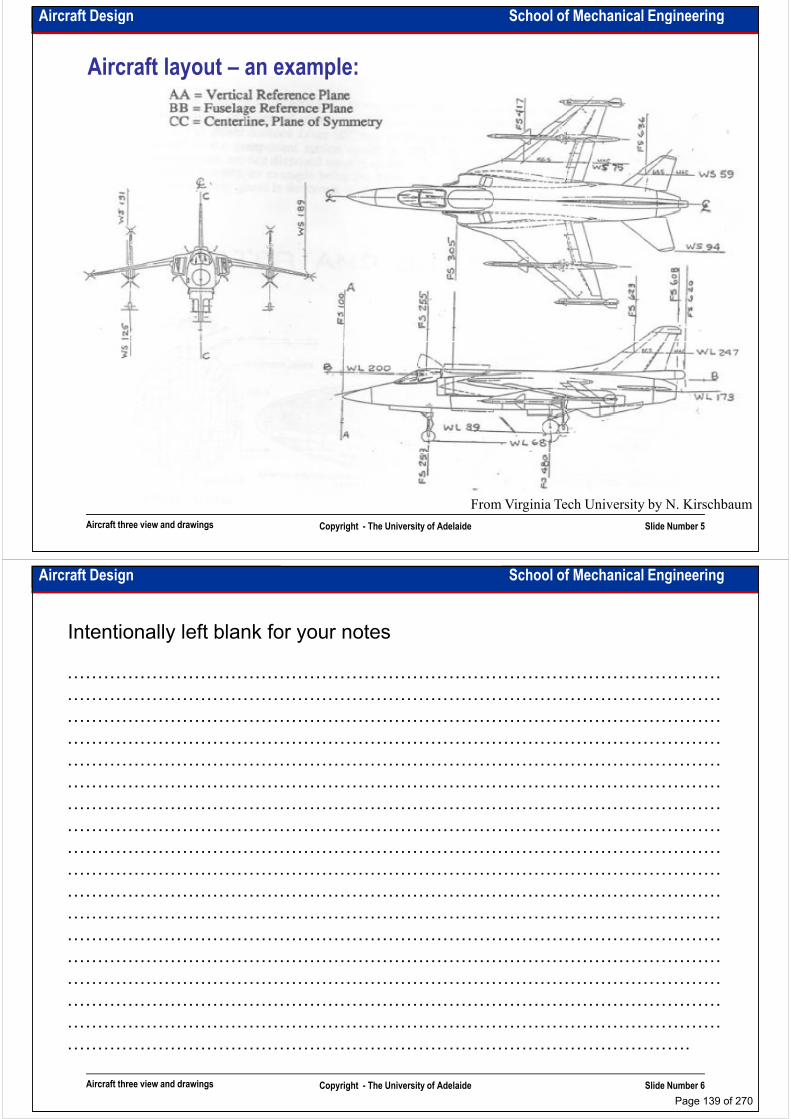
Aircraft Design School of Mechanical Engineering
Aircraft layout – an example:
Aircraft three view and drawings Copyright - The University of Adelaide Slide Number 5
From Virginia Tech University by N. Kirschbaum
Aircraft Design School of Mechanical Engineering
Intentionally left blank for your notes
………………………………………………………………………………………………
………………………………………………………………………………………………
………………………………………………………………………………………………
………………………………………………………………………………………………………………………………………………………………………………………………
………………………………………………………………………………………………
………………………………………………………………………………………………
………………………………………………………………………………………………
………………………………………………………………………………………………
………………………………………………………………………………………………
………………………………………………………………………………………………
………………………………………………………………………………………………
………………………………………………………………………………………………
………………………………………………………………………………………………
Aircraft three view and drawings Copyright - The University of Adelaide Slide Number 6
………………………………………………………………………………………………
………………………………………………………………………………………………
………………………………………………………………………………………………
………………………………………………………………………………………………
………………………………………………………………………………………………
………………………………………………………………………………………….
Page 139 of 270
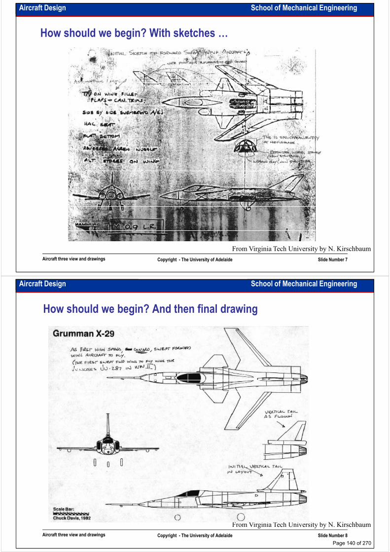
Aircraft Design School of Mechanical Engineering
How should we begin? With sketches …
Aircraft three view and drawings Copyright - The University of Adelaide Slide Number 7
From Virginia Tech University by N. Kirschbaum
Aircraft Design School of Mechanical Engineering
How should we begin? And then final drawing
Aircraft three view and drawings Copyright - The University of Adelaide Slide Number 8
From Virginia Tech University by N. Kirschbaum
Page 140 of 270

Aircraft Design School of Mechanical Engineering
How should we begin? With sketches …
Aircraft three view and drawings Copyright - The University of Adelaide Slide Number 9
From Virginia Tech University by N. Kirschbaum
Aircraft Design School of Mechanical Engineering
How should we begin? And then final drawing
Aircraft three view and drawings Copyright - The University of Adelaide Slide Number 10
From Virginia Tech University by N. Kirschbaum
Page 141 of 270
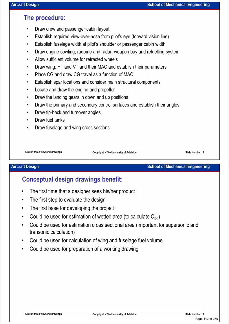
Aircraft Design School of Mechanical Engineering
The procedure:
• Draw crew and passenger cabin layout
• Establish required view-over-nose from pilot’s eye (forward vision line)
• Establish fuselage width at pilot's shoulder or passenger cabin width
• Draw engine cowling, radome and radar, weapon bay and refuelling system
• Allow sufficient volume for retracted wheels
• Draw wing, HT and VT and their MAC and establish their parameters
• Place CG and draw CG travel as a function of MAC
• Establish spar locations and consider main structural components
• Locate and draw the engine and propeller
• Draw the landing gears in down and up positions
• Draw the primary and secondary control surfaces and establish their angles
Aircraft three view and drawings Copyright - The University of Adelaide Slide Number 11
• Draw the primary and secondary control surfaces and establish their angles
• Draw tip-back and turnover angles
• Draw fuel tanks
• Draw fuselage and wing cross sections
Aircraft Design School of Mechanical Engineering
Conceptual design drawings benefit:
• The first time that a designer sees his/her product
• The first step to evaluate the design
• The first base for developing the project
• Could be used for estimation of wetted area (to calculate CD0)• Could be used for estimation of wetted area (to calculate CD0)
• Could be used for estimation cross sectional area (important for supersonic and
transonic calculation)
• Could be used for calculation of wing and fuselage fuel volume
• Could be used for preparation of a working drawing
Aircraft three view and drawings Copyright - The University of Adelaide Slide Number 12
Page 142 of 270

Aircraft Design School of Mechanical Engineering
Working drawing:
• The main drawing in aircraft design
• The drawing which faces maximum changes as the design information grows up
• The drawing, which all the detail design processes are based on
• It contains:• It contains:
– Fuselage cross section layout and profile in different Fuselage Stations
– Aircraft grounding configuration
– Aircraft operation hints
– Top and side inboard profiles
– Structural configurations
– Main systems layout (fuel system, control panel, flight system,…)
Aircraft three view and drawings Copyright - The University of Adelaide Slide Number 13
Aircraft Design School of Mechanical Engineering
A working drawing example:
Aircraft three view and drawings Copyright - The University of Adelaide Slide Number 14
From Virginia Tech University by W.H. Mawson
Page 143 of 270
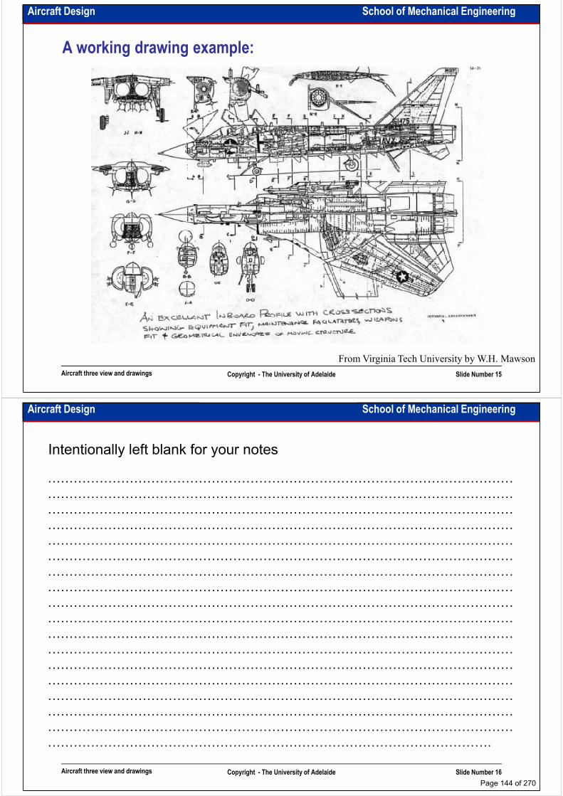
Aircraft Design School of Mechanical Engineering
A working drawing example:
Aircraft three view and drawings Copyright - The University of Adelaide Slide Number 15
From Virginia Tech University by W.H. Mawson
Aircraft Design School of Mechanical Engineering
Intentionally left blank for your notes
………………………………………………………………………………………………
………………………………………………………………………………………………
………………………………………………………………………………………………
………………………………………………………………………………………………………………………………………………………………………………………………
………………………………………………………………………………………………
………………………………………………………………………………………………
………………………………………………………………………………………………
………………………………………………………………………………………………
………………………………………………………………………………………………
………………………………………………………………………………………………
………………………………………………………………………………………………
………………………………………………………………………………………………
………………………………………………………………………………………………
Aircraft three view and drawings Copyright - The University of Adelaide Slide Number 16
………………………………………………………………………………………………
………………………………………………………………………………………………
………………………………………………………………………………………………
………………………………………………………………………………………………
………………………………………………………………………………………………
………………………………………………………………………………………….
Page 144 of 270

Aircraft Design School of Mechanical Engineering
A working drawing example:
Aircraft three view and drawings Copyright - The University of Adelaide Slide Number 17
From Virginia Tech University by W.H. Mawson
Aircraft Design School of Mechanical Engineering
And …
• The drawing should “talk” to the others
• A weak drawing is a drawing that needs to be explained by the drawer
• Check the weights, balance and performance more than one times to ensure that
you draw your aircraftyou draw your aircraft
• Don’t try to do a combined drawing using usual softwares and computers
• Everything that is drawn in your drawings should have a calculation or explanation
as it’s backup
• And
A good aircraft must be BEAUTIFUL
Aircraft three view and drawings Copyright - The University of Adelaide Slide Number 18
A good aircraft must be BEAUTIFUL
Page 145 of 270
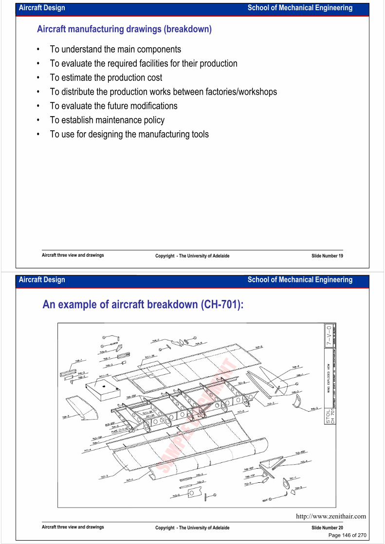
Aircraft Design School of Mechanical Engineering
Aircraft manufacturing drawings (breakdown)
• To understand the main components
• To evaluate the required facilities for their production
• To estimate the production cost
• To distribute the production works between factories/workshops• To distribute the production works between factories/workshops
• To evaluate the future modifications
• To establish maintenance policy
• To use for designing the manufacturing tools
Aircraft three view and drawings Copyright - The University of Adelaide Slide Number 19
Aircraft Design School of Mechanical Engineering
An example of aircraft breakdown (CH-701):
Aircraft three view and drawings Copyright - The University of Adelaide Slide Number 20
http://www.zenithair.com
Page 146 of 270
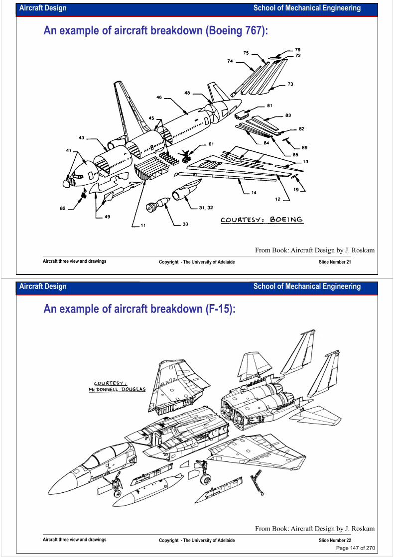
Aircraft Design School of Mechanical Engineering
An example of aircraft breakdown (Boeing 767):
Aircraft three view and drawings Copyright - The University of Adelaide Slide Number 21
From Book: Aircraft Design by J. Roskam
Aircraft Design School of Mechanical Engineering
An example of aircraft breakdown (F-15):
Aircraft three view and drawings Copyright - The University of Adelaide Slide Number 22
From Book: Aircraft Design by J. Roskam
Page 147 of 270

Aircraft Design School of Mechanical Engineering
Aircraft terminology:
Aircraft three view and drawings Copyright - The University of Adelaide Slide Number 23
http://www.dlis.dla.mil/fiigdata
Aircraft Design School of Mechanical Engineering
Intentionally left blank for your notes
………………………………………………………………………………………………
………………………………………………………………………………………………
………………………………………………………………………………………………
………………………………………………………………………………………………………………………………………………………………………………………………
………………………………………………………………………………………………
………………………………………………………………………………………………
………………………………………………………………………………………………
………………………………………………………………………………………………
………………………………………………………………………………………………
………………………………………………………………………………………………
………………………………………………………………………………………………
………………………………………………………………………………………………
………………………………………………………………………………………………
Aircraft three view and drawings Copyright - The University of Adelaide Slide Number 24
………………………………………………………………………………………………
………………………………………………………………………………………………
………………………………………………………………………………………………
………………………………………………………………………………………………
………………………………………………………………………………………………
………………………………………………………………………………………….
Page 148 of 270
School of Mechanical EngineeringAircraft Design
Overall configuration design (I)
Dr. MAZIAR ARJOMANDI
Semester I
Overall configuration design (I) Copyright - The University of Adelaide Slide Number 1
Semester I
Aircraft Design School of Mechanical Engineering
What do we begin from?
• We have already calculated weight, thrust/power and wing area.
• Overall configuration design is the first step of aircraft configuration design.
• Read TT carefully and consider those items which may have a major impact on
the design.the design.
• Perform a comparative analysis of the designed and built aircraft similar to your
aircraft.
• Remember that a good question may receive a good answer. Try to discuss with
your colleagues your idea.
• Think simply! Don’t try to answer the simple questions with the hard answers.
• There are no absolute pros and cons in aircraft design. They are all relative.
• Use clear sketches instead of explaining your idea. Engineering sketches must
Overall configuration design (I) Copyright - The University of Adelaide Slide Number 2
• Use clear sketches instead of explaining your idea. Engineering sketches must
play the main role in your meetings and discussions.
• Don’t try to make a revolution in aircraft design by unnecessarily choosing
unusual configuration. However to move the engineering knowledge forward
you have to be brave and make the unusual decisions.
Page 149 of 270
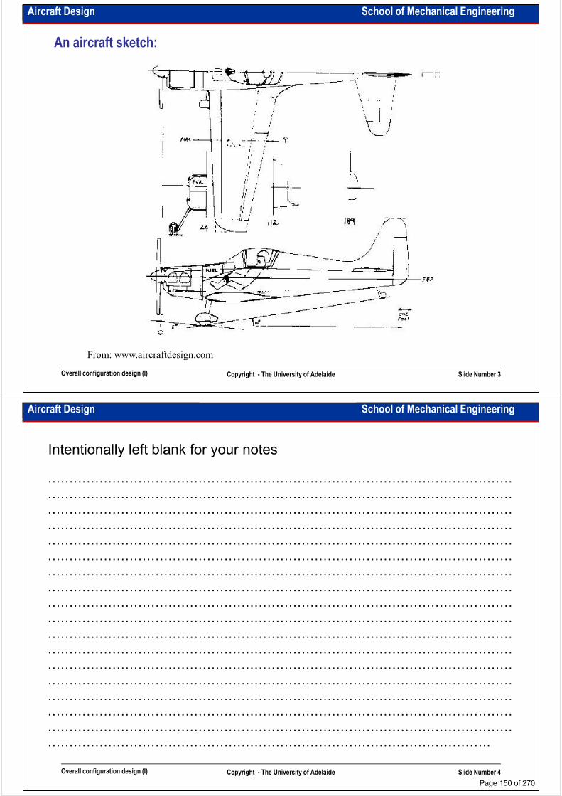
Aircraft Design School of Mechanical Engineering
An aircraft sketch:
Overall configuration design (I) Copyright - The University of Adelaide Slide Number 3
From: www.aircraftdesign.com
Aircraft Design School of Mechanical Engineering
Intentionally left blank for your notes
………………………………………………………………………………………………
………………………………………………………………………………………………
………………………………………………………………………………………………
………………………………………………………………………………………………………………………………………………………………………………………………
………………………………………………………………………………………………
………………………………………………………………………………………………
………………………………………………………………………………………………
………………………………………………………………………………………………
………………………………………………………………………………………………
………………………………………………………………………………………………
………………………………………………………………………………………………
………………………………………………………………………………………………
………………………………………………………………………………………………
Overall configuration design (I) Copyright - The University of Adelaide Slide Number 4
………………………………………………………………………………………………
………………………………………………………………………………………………
………………………………………………………………………………………………
………………………………………………………………………………………………
………………………………………………………………………………………………
………………………………………………………………………………………….
Page 150 of 270
Aircraft Design School of Mechanical Engineering
Homebuilt aircraft design considerations:
• They are designed and built by one or two persons (enthusiastic)
• They are usually tested in the sky (no wind tunnel or structural testing)
• They are unreliable and can not receive certification
• They are made of cheap materials with low level of manufacturing technology• They are made of cheap materials with low level of manufacturing technology
• They are very inefficient
• A lot of brave design decisions may be discovered in the current homebuilt
aircraft
• Homebuilt aircraft usually are designed and built without any TT (technical
task), CD (conceptual design) documents and PD (preliminary design) or DD
(detail design) drawings
• A homebuilt aircraft designer is happy if his/her aircraft flies. He/she is not
Overall configuration design (I) Copyright - The University of Adelaide Slide Number 5
• A homebuilt aircraft designer is happy if his/her aircraft flies. He/she is not
interested to know the flight efficiency or measure the quality of flight. No
competitors!
Aircraft Design School of Mechanical Engineering
Homebuilt aircraft configurations:
• As it is very hard to solve the problem of stability of a canard, tandem wing or three-
surface aircraft, homebuilt aircraft generally have conventional configuration
• Intention of some builders to park their aircraft in their carport leads to wing-fold
mechanism and also easily mountable configurationsmechanism and also easily mountable configurations
• Because of the cost, homebuilt aircraft usually have fixed-landing gears. Some
designers choose tail-dragger as they use their aircraft as a hubby for
entertainment and no need to keep the aircraft stable on the ground roll in bad
weather conditions
• They have tractor or pusher engines (mainly piston engines)
• In homebuilt aircraft the wing positioning, structure and planform may be widely
different. It mainly depends on the amount of money which the builder intends to
Overall configuration design (I) Copyright - The University of Adelaide Slide Number 6
different. It mainly depends on the amount of money which the builder intends to
spend.
• Recently some of the builders choose pre-manufactured kits. Kit airplanes could
receive certification. They are more efficient, more reliable and somehow cheap
and help the builder to make a good aircraft without being a designer. Kits usually
have conventional configuration.
Page 151 of 270
Aircraft Design School of Mechanical Engineering
General Aviation (GA) aircraft design considerations:
• They are designed and built by the small companies.
• There are a few GA aircraft which are tested in wind tunnels. It depends on the
quantity of the aircraft planned to be manufactured.
• They are mainly certified according to part-23.• They are mainly certified according to part-23.
• There is a tendency to make GA aircraft from composite materials.
• They could be used for carrying passengers and freight, pilot training,
entertainment and …
• All of them should be somehow user-friendly in operation as they may
operate by low-skilled pilots.
• They are very popular in North America (nearly 80% of all GA aircraft fly in
US)
Overall configuration design (I) Copyright - The University of Adelaide Slide Number 7
US)
• There is a tendency to replace current AVGAS engines with JET A piston
engines as JET A is much more cheaper.
• A few GA aircraft are designed with jet engines. The interest to use small
private aircraft for long ranges with higher speed is increasing.
Aircraft Design School of Mechanical Engineering
Intentionally left blank for your notes
………………………………………………………………………………………………
………………………………………………………………………………………………
………………………………………………………………………………………………
………………………………………………………………………………………………………………………………………………………………………………………………
………………………………………………………………………………………………
………………………………………………………………………………………………
………………………………………………………………………………………………
………………………………………………………………………………………………
………………………………………………………………………………………………
………………………………………………………………………………………………
………………………………………………………………………………………………
………………………………………………………………………………………………
………………………………………………………………………………………………
Overall configuration design (I) Copyright - The University of Adelaide Slide Number 8
………………………………………………………………………………………………
………………………………………………………………………………………………
………………………………………………………………………………………………
………………………………………………………………………………………………
………………………………………………………………………………………………
………………………………………………………………………………………….
Page 152 of 270
Aircraft Design School of Mechanical Engineering
General Aviation (GA) aircraft configurations:
• As GA aircraft can be operated by low-skilled pilots they should be good in
handling. GA aircraft generally have conventional configuration, although a few
of them have canard configuration.
• Both fixed and retractable landing gears could be seen on these aircraft • Both fixed and retractable landing gears could be seen on these aircraft
(retractable landing gears are used more on twin engines ). Tail-dragger is
rarely used as it makes the aircraft unstable on the ground in bad weather
conditions.
• They have one or two tractor or pusher engines (mainly piston and turboprop
engines)
• The category of the aircraft (Normal, Utility, Acrobatic) usually dictates the
wing planform (variable or constant wing chord), wing twist and airfoil and
Overall configuration design (I) Copyright - The University of Adelaide Slide Number 9
horizontal tail positioning according to vertical tail.
• In one-engine GA aircraft, engine is usually mounted on the fuselage (pusher or
tractor and in two-engine configuration, engines are mounted on the wing,
although the other configurations are available (depending on the aircraft
application, e.g. amphibious aircraft)
Aircraft Design School of Mechanical Engineering
Agricultural aircraft design considerations:
• They are designed and built specifically for agricultural purposes. There are a few GA
aircraft modified for agricultural purposes but they are less efficient.
• They have very low aerodynamic efficiency. Structural testing is more important
than wind tunnel testing.
• They are mainly certified according to part-23 and additional special standards.
• The needs of structural repairs in the fields prevent enhanced usage of composite
materials in agricultural aircraft structure, although the usage of composite materials is
increasing.
• They could be used for different types of agricultural operation like pesticide spraying,
seeding and …
• They should be designed for the operation in harsh environment.
• There is a tendency to use small aircraft like kites, autogyros and unmanned
Overall configuration design (I) Copyright - The University of Adelaide Slide Number 10
• There is a tendency to use small aircraft like kites, autogyros and unmanned
helicopters for agricultural purposes especially in Asian countries as the farms are
small and most of them are placed between the hills and near the mountains.
• They are designed to cover more ground area in one hour flight, so they should be
enough manoeuvrable and able to fly at low altitudes.
Page 153 of 270

Aircraft Design School of Mechanical Engineering
Agricultural aircraft configurations:
• They usually have low-wing conventional configuration. A few of them have biplane
configuration. In high-wing configuration it is necessary to add extra components for
mounting the sprayers.
• Most of them have tail-dragger fixed landing gears. It helps their operation from very
rough fields. It also reduces the operation and maintenance cost.rough fields. It also reduces the operation and maintenance cost.
• They mainly have one or two tractor engines (piston or turboprop engines are used).
Tendency to use tractor engines because of placing the payload in nose section
enormously increases CG travelling during operation.
• They usually have simple wing planform, constant chord with no twist as their operational
speed is very low.
• They generally configured with raised cockpits as pilot visibility is absolutely essential
for agricultural aircraft and also agricultural aircraft tend to have relatively long nose for
placing the payload.
Overall configuration design (I) Copyright - The University of Adelaide Slide Number 11
placing the payload.
• They have some supportive structure for crashworthiness considerations.
• All agricultural aircraft have bird-proof windshield, wire cutters and wire deflectors as
they fly extremely near the ground.
Aircraft Design School of Mechanical Engineering
Intentionally left blank for your notes
………………………………………………………………………………………………
………………………………………………………………………………………………
………………………………………………………………………………………………
………………………………………………………………………………………………………………………………………………………………………………………………
………………………………………………………………………………………………
………………………………………………………………………………………………
………………………………………………………………………………………………
………………………………………………………………………………………………
………………………………………………………………………………………………
………………………………………………………………………………………………
………………………………………………………………………………………………
………………………………………………………………………………………………
………………………………………………………………………………………………
Overall configuration design (I) Copyright - The University of Adelaide Slide Number 12
………………………………………………………………………………………………
………………………………………………………………………………………………
………………………………………………………………………………………………
………………………………………………………………………………………………
………………………………………………………………………………………………
………………………………………………………………………………………….
Page 154 of 270
Aircraft Design School of Mechanical Engineering
Business jet design considerations:
• They are designed and built by the big companies.
• They are usually tested in wind tunnels and have good aerodynamic
efficiency.
• They are mainly certified according to part-23.• They are mainly certified according to part-23.
• There is a tendency to increase the usage of composite materials in
business jets.
• They are generally used for carrying passengers and freight. They are also
used by the army in military operations.
• They are piloted by well trained pilots.
• There is a tendency to increase the range and the cruise speed of business
jets as businessmen like to travel faster and farer.
Overall configuration design (I) Copyright - The University of Adelaide Slide Number 13
jets as businessmen like to travel faster and farer.
• They are usually designed to carry 6-15 passengers. In some cases they have
very luxurious comfortable cabin with all business facilities.
Aircraft Design School of Mechanical Engineering
Business jet configurations:
• Most of them have low-wing configuration. It seems that low wing configuration aircraft
with the combination of rather short fuselage require smaller vertical tail, consequently
they weigh less.
• All of them have tricycle retractable landing gears. They are usually operated on the
hard runways and should be proper for operation in the bad weather conditions.hard runways and should be proper for operation in the bad weather conditions.
• They mainly have two or more turbofan/turbojet engines, installed on the aft section of
the fuselage as the wing in low-wing configuration is quite near to the ground surface.
• They usually have well-designed wing planform, variable chord with precise twist and
incidence angles. The first wingtips and supercritical airfoils were used on business jets.
• Business jets are usually designed to be stand alone in operation. They have folding
stairs or stair-door combination.
• Their structures and systems should be designed to be very reliable.
Overall configuration design (I) Copyright - The University of Adelaide Slide Number 14
• Their structures and systems should be designed to be very reliable.
• They usually have conventional configuration, although a few of them have canard
configuration.
Page 155 of 270
Aircraft Design School of Mechanical Engineering
Jet transport design considerations:
• They are designed and built by the big companies or international joint ventures.
• They are usually tested in wind tunnels and have good aerodynamic efficiency.
Before manufacturing and even during manufacturing they are modified for many
times.
• They are designed and made with the flexibility of further modification.
• They are mainly certified according to part-25. Their operations are also standardised.
• There is a tendency to increase the usage of composite materials in jet transports.
• They are generally used for carrying passengers and freight. They are also used by the
army in military operations.
• They are piloted by well trained pilots. (However, the pilots’ mistake is the reason of
nearly 70% of air crashes)
• There is a tendency to increase the range and the cruise speed of business jets.
Overall configuration design (I) Copyright - The University of Adelaide Slide Number 15
• There is a tendency to increase the range and the cruise speed of business jets.
One of the reasons of that is the economic growth of Fareast countries.
• They are usually designed to carry 50 passengers and more up to 1000 in different
cabin configurations.
Aircraft Design School of Mechanical Engineering
Intentionally left blank for your notes
………………………………………………………………………………………………
………………………………………………………………………………………………
………………………………………………………………………………………………
………………………………………………………………………………………………………………………………………………………………………………………………
………………………………………………………………………………………………
………………………………………………………………………………………………
………………………………………………………………………………………………
………………………………………………………………………………………………
………………………………………………………………………………………………
………………………………………………………………………………………………
………………………………………………………………………………………………
………………………………………………………………………………………………
………………………………………………………………………………………………
Overall configuration design (I) Copyright - The University of Adelaide Slide Number 16
………………………………………………………………………………………………
………………………………………………………………………………………………
………………………………………………………………………………………………
………………………………………………………………………………………………
………………………………………………………………………………………………
………………………………………………………………………………………….
Page 156 of 270
Aircraft Design School of Mechanical Engineering
Jet transport configurations:
• Most of them have low-wing configuration. It helps to keep the fuselage and passenger
cabins safe in a crash. (In high wing configuration wing weight and impact should be
damped by fuselage) (in an emergency landing on the water high-wing aircraft can stay
more on the water)
• All of them have tricycle retractable landing gears. They are usually operated on the • All of them have tricycle retractable landing gears. They are usually operated on the
hard runways and should be proper for operation in the bad weather conditions.
• They mainly have two or more turbofan/turbojet engines, installed under the wings or on
the aft fuselage. To reduce the noise there is a tendency not to install the engines on the
fuselage.
• They usually have well-designed wing planform, variable chord with precise twist,
sweep and incidence angles.
• To keep their structure as light as possible, they usually don’t carry stairs (except the old
types). They need to be serviced by ground units after landing.
Overall configuration design (I) Copyright - The University of Adelaide Slide Number 17
types). They need to be serviced by ground units after landing.
• Their structures and systems should be designed to be very reliable.
• They usually have conventional configuration. The other configurations are not seen on
jet transports.
• To design jet transports, passenger comforts must be considered
Aircraft Design School of Mechanical Engineering
Intentionally left blank for your notes
………………………………………………………………………………………………
………………………………………………………………………………………………
………………………………………………………………………………………………
………………………………………………………………………………………………………………………………………………………………………………………………
………………………………………………………………………………………………
………………………………………………………………………………………………
………………………………………………………………………………………………
………………………………………………………………………………………………
………………………………………………………………………………………………
………………………………………………………………………………………………
………………………………………………………………………………………………
………………………………………………………………………………………………
………………………………………………………………………………………………
Overall configuration design (I) Copyright - The University of Adelaide Slide Number 18
………………………………………………………………………………………………
………………………………………………………………………………………………
………………………………………………………………………………………………
………………………………………………………………………………………………
………………………………………………………………………………………………
………………………………………………………………………………………….
Page 157 of 270

School of Mechanical EngineeringAircraft Design
Overall configuration design (II)
Dr. MAZIAR ARJOMANDI
Semester I
Overall configuration design (II) Copyright - The University of Adelaide Slide Number 1
Semester I
Aircraft Design School of Mechanical Engineering
Military trainer design considerations:
• They are designed and built by the big companies (usually fighter designers and
manufacturers).
• They are usually tested in wind tunnels.
• They must be able to simulate the flight of a specific type/types of fighters. • They must be able to simulate the flight of a specific type/types of fighters.
• They should be able to demonstrate flight on high angle of attacks and high load factor
manoeuvres.
• They are mainly certified according to MIL standards.
• There is a tendency to increase the usage of composite materials in military trainers.
• To make the aircraft more flexible and able to simulate more than one type of fighters,
FBW is used as the main control system.
• They are used not only for training the pilots but also for their rehabilitation. In many
countries for reduction the air force's expenses, pilots use military trainers for daily flight
Overall configuration design (II) Copyright - The University of Adelaide Slide Number 2
countries for reduction the air force's expenses, pilots use military trainers for daily flight
hours.
• They are piloted by pilots with different skill levels. (primary, type and advanced training)
• They are usually designed to be operated by two pilots, trainer and trainee.
• They should be very cheap in operation.
Page 158 of 270

Aircraft Design School of Mechanical Engineering
Military trainer configurations:
• Most of them have low-wing or mid-wing configuration, although high-wing
configuration is also used.
• All of them have tricycle retractable landing gears. They are usually operated on the
hard runways.
• They mainly have one or two turboprop/turbojet engines, installed on/in the for or aft • They mainly have one or two turboprop/turbojet engines, installed on/in the for or aft
part of the fuselage. All the turboprop configuration aircraft are tractor. The turboprop
configuration is generally used on the aircraft for basic or initial training.
• They usually have well-designed wing planform, variable chord with precise twist,
sweep and incidence angles.
• There are different types of strakes and fins on military trainers. The reason of that could
be probably weak response of aircraft to the spin recovery or other stability issues which
were revealed during flight tests. (it is usual for the fighters as well)
Overall configuration design (II) Copyright - The University of Adelaide Slide Number 3
• They usually have conventional configuration. The other configurations are not seen
on military trainers.
• The capability of carrying the weapons should be considered.
Aircraft Design School of Mechanical Engineering
Intentionally left blank for your notes
………………………………………………………………………………………………
………………………………………………………………………………………………
………………………………………………………………………………………………
………………………………………………………………………………………………………………………………………………………………………………………………
………………………………………………………………………………………………
………………………………………………………………………………………………
………………………………………………………………………………………………
………………………………………………………………………………………………
………………………………………………………………………………………………
………………………………………………………………………………………………
………………………………………………………………………………………………
………………………………………………………………………………………………
………………………………………………………………………………………………
Overall configuration design (II) Copyright - The University of Adelaide Slide Number 4
………………………………………………………………………………………………
………………………………………………………………………………………………
………………………………………………………………………………………………
………………………………………………………………………………………………
………………………………………………………………………………………………
………………………………………………………………………………………….
Page 159 of 270
Aircraft Design School of Mechanical Engineering
Fighter design considerations:
• They are designed and built by big or joint venture international companies
(traditionally they are built in a few countries).
• Their design process needs 10-20 years.
• They are usually tested in wind tunnels.
• The main parameter of designing a fighter is its ability to win the potential enemy fighter • The main parameter of designing a fighter is its ability to win the potential enemy fighter
(forget about fuel consumption and weight, however aircraft cost should be considered as
the number of aircraft could guaranty the superiority).
• They are mainly certified according to MIL standards.
• There is a tendency to increase the usage of composite materials in military trainers.
• There is a tendency to increase manoeuvrability of the fighters (negative static margin,
LEX and thrust vectoring).
• Fighters are the most complicated machines which are built by human (advance
Overall configuration design (II) Copyright - The University of Adelaide Slide Number 5
• Fighters are the most complicated machines which are built by human (advance
aerodynamic design, production technology, smart materials, complex propulsion system,
avionics and weapon systems).
• They are piloted by one/two skilled pilots.
• They could be designed for different types of operations (surveillance, reconnaissance,
ground attack, close air support, air defence, homeland security and …).
Aircraft Design School of Mechanical Engineering
Fighter configurations:
• Air superiority fighters usually have mid-wing configurations, close air support fighters
have low-wing configuration and fighters with variable wing sweep angle have high-
wing configuration.
• Variable wing sweep angle configuration is very expensive. It can not be seen on modern
fighters and instead they use wings with different sweep angles for each wing part.fighters and instead they use wings with different sweep angles for each wing part.
• Most of them have tricycle retractable landing gears. They are usually operated on the
hard runways. Some of them have very complicated landing gears which allow them to
land on the carriers, on icy surfaces and also on unpaved runways.
• The modern fighters mainly have one or two turbojet/afterburning-
turbojet/afterburning-turbofan engines, installed on/in the aft part of the fuselage.
• They usually have well-designed wing planform, variable chord with precise twist,
sweep and incidence angles.
• There are different types of strakes and fins on fighters. The reason of that could be
Overall configuration design (II) Copyright - The University of Adelaide Slide Number 6
• There are different types of strakes and fins on fighters. The reason of that could be
probably weak response of aircraft to the spin recovery or other stability issues which
were revealed during flight tests. (it is rarely seen on the modern fighters)
• They usually have conventional configuration. Canard configuration is not very popular.
There is a tendency toward three-surface configuration (tail+canard+wing)
• Fighters should be able to carry weapons inside/under the wing and fuselage.
Page 160 of 270
Aircraft Design School of Mechanical Engineering
Military patrol and transport aircraft design considerations:
• They are designed and built by big companies or international joint ventures.
• They are usually tested in wind tunnels and have good aerodynamic efficiency. In some cases their wing and body are inherited from passenger aircraft.
• A military patrol and transport aircraft is usually designed and made as a multipurpose flying platform.multipurpose flying platform.
• They are mainly certified according to MIL standards.
• There is a tendency to increase the usage of composite materials in military patrols and transport aircraft.
• They are generally used for carrying troops, freight and special purpose devices. They are also used for civil operation in natural disasters.
• They are piloted by one/two well trained pilots. Some of them have a team of pilots to reduce the flight load on the pilots in long distance and high endurance operations.
• There is a tendency to increase the range and loitering time of military patrol and
Overall configuration design (II) Copyright - The University of Adelaide Slide Number 7
• There is a tendency to increase the range and loitering time of military patrol and transport aircraft.
• They could be designed for different types of operations (surveillance, reconnaissance, troop transportation, paratroops dropping, air logistics, search and rescue, air refuelling, long range bombing and …).
• There is a tendency to design and build the long range bombers more stealthy.
Aircraft Design School of Mechanical Engineering
Intentionally left blank for your notes
………………………………………………………………………………………………
………………………………………………………………………………………………
………………………………………………………………………………………………
………………………………………………………………………………………………………………………………………………………………………………………………
………………………………………………………………………………………………
………………………………………………………………………………………………
………………………………………………………………………………………………
………………………………………………………………………………………………
………………………………………………………………………………………………
………………………………………………………………………………………………
………………………………………………………………………………………………
………………………………………………………………………………………………
………………………………………………………………………………………………
Overall configuration design (II) Copyright - The University of Adelaide Slide Number 8
………………………………………………………………………………………………
………………………………………………………………………………………………
………………………………………………………………………………………………
………………………………………………………………………………………………
………………………………………………………………………………………………
………………………………………………………………………………………….
Page 161 of 270
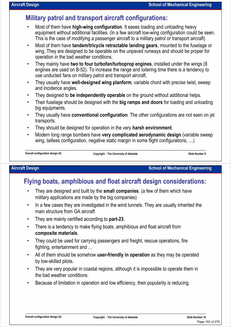
Aircraft Design School of Mechanical Engineering
Military patrol and transport aircraft configurations:
• Most of them have high-wing configuration. It eases loading and unloading heavy equipment without additional facilities. (In a few aircraft low-wing configuration could be seen. This is the case of modifying a passenger aircraft to a military patrol or transport aircraft)
• Most of them have tandem/tricycle retractable landing gears, mounted to the fuselage or wing. They are designed to be operable on the unpaved runways and should be proper for operation in the bad weather conditions.operation in the bad weather conditions.
• They mainly have two to four turbofan/turboprop engines, installed under the wings (8 engines are used on B-52). To increase the range and loitering time there is a tendency to use unducted fans on military patrol and transport aircraft.
• They usually have well-designed wing planform, variable chord with precise twist, sweep and incidence angles.
• They designed to be independently operable on the ground without additional helps.
• Their fuselage should be designed with the big ramps and doors for loading and unloading big equipments.
Overall configuration design (II) Copyright - The University of Adelaide Slide Number 9
big equipments.
• They usually have conventional configuration. The other configurations are not seen on jet transports.
• They should be designed for operation in the very harsh environment.
• Modern long range bombers have very complicated aerodynamic design (variable sweep wing, tailless configuration, negative static margin in some flight configurations, …)
Aircraft Design School of Mechanical Engineering
Flying boats, amphibious and float aircraft design considerations:
• They are designed and built by the small companies. (a few of them which have
military applications are made by the big companies)
• In a few cases they are investigated in the wind tunnels. They are usually inherited the
main structure from GA aircraft
• They are mainly certified according to part-23.• They are mainly certified according to part-23.
• There is a tendency to make flying boats, amphibious and float aircraft from
composite materials.
• They could be used for carrying passengers and freight, rescue operations, fire
fighting, entertainment and …
• All of them should be somehow user-friendly in operation as they may be operated
by low-skilled pilots.
• They are very popular in coastal regions, although it is impossible to operate them in
Overall configuration design (II) Copyright - The University of Adelaide Slide Number 10
• They are very popular in coastal regions, although it is impossible to operate them in
the bad weather conditions.
• Because of limitation in operation and low efficiency, their popularity is reducing.
Page 162 of 270
Aircraft Design School of Mechanical Engineering
Flying boats, amphibious and float aircraft configurations:
• Most of them have high-wing configuration. The reason of that is the necessity of
engine installation far from the water surface. (In a few aircraft low-wing configuration
could be seen. In this case engines are installed on the fuselage)
• Most of them have tricycle/tail dragger retractable/fixed landing gears in a combination
with the fixed floats/hull. with the fixed floats/hull.
• New amphibious aircraft mainly have two piston/turboprop/turbofan engines, installed
on/under the wings. They have rational high thrust/power loading as the engines should
generate enough power/thrust to accelerate the aircraft on the water.
• They usually have poorly-designed wing planform as generated drag by hull is so
considerable that the benefits in drag amount by using more proper wing planform could
be neglected.
• They should be designed for operation in the very harsh environment. Their structure
should be designed with the consideration of sea-water influence on its materials.
Overall configuration design (II) Copyright - The University of Adelaide Slide Number 11
should be designed with the consideration of sea-water influence on its materials.
• They usually have conventional configuration.
• Ability to land on the wavy water surface, preventing water droplet into the engines and
air intakes, reducing frontal drag area and easy handling on the water are the main
challenges in designing the Flying boats, amphibious and float aircraft.
Aircraft Design School of Mechanical Engineering
Intentionally left blank for your notes
………………………………………………………………………………………………
………………………………………………………………………………………………
………………………………………………………………………………………………
………………………………………………………………………………………………………………………………………………………………………………………………
………………………………………………………………………………………………
………………………………………………………………………………………………
………………………………………………………………………………………………
………………………………………………………………………………………………
………………………………………………………………………………………………
………………………………………………………………………………………………
………………………………………………………………………………………………
………………………………………………………………………………………………
………………………………………………………………………………………………
Overall configuration design (II) Copyright - The University of Adelaide Slide Number 12
………………………………………………………………………………………………
………………………………………………………………………………………………
………………………………………………………………………………………………
………………………………………………………………………………………………
………………………………………………………………………………………………
………………………………………………………………………………………….
Page 163 of 270

Aircraft Design School of Mechanical Engineering
And…
Don’t forget:
Nothing is absolute in design. Everything is relative.
Design is creativity.
Remember:
Synthesis (idea generation),
analysis (idea evolution),
decision making.
Overall configuration design (II) Copyright - The University of Adelaide Slide Number 13
Aircraft Design School of Mechanical Engineering
Intentionally left blank for your notes
………………………………………………………………………………………………
………………………………………………………………………………………………
………………………………………………………………………………………………
………………………………………………………………………………………………………………………………………………………………………………………………
………………………………………………………………………………………………
………………………………………………………………………………………………
………………………………………………………………………………………………
………………………………………………………………………………………………
………………………………………………………………………………………………
………………………………………………………………………………………………
………………………………………………………………………………………………
………………………………………………………………………………………………
………………………………………………………………………………………………
Overall configuration design (II) Copyright - The University of Adelaide Slide Number 14
………………………………………………………………………………………………
………………………………………………………………………………………………
………………………………………………………………………………………………
………………………………………………………………………………………………
………………………………………………………………………………………………
………………………………………………………………………………………….
Page 164 of 270
School of Mechanical EngineeringAircraft Design
Fuselage design (crew and passenger cabin Fuselage design (crew and passenger cabin
design)
Dr. MAZIAR ARJOMANDI
Semester I
Fuselage design (crew and passenger
cabin design)
Copyright - The University of Adelaide Slide Number 1
Semester I
Aircraft Design School of Mechanical Engineering
Fuselage main functions:
• To provide space for payloads
• To isolate payloads from free airstreams
• To integrate aircraft parts
• To transfer the main loads to the “aircraft
We will review the followings:
– Crew cabin design
– Passenger cabin design
– Cargo and baggage compartment
design
– Fuselage overall designneutral point” where they balance each other – Fuselage overall design
• Crew members must be comfort in their positions
• Crew members must be restrained in their positions
• Crew members must have easy and comfortable access to all required flight controls
Crew cabin design – main considerations:
Fuselage design (crew and passenger
cabin design)Copyright - The University of Adelaide Slide Number 2
• Crew members must have easy and comfortable access to all required flight controls
• Crew members must be able to see all indicators without undue effort
• Crew members must have minimum standard visibility from cabin
• Crew members must be able to communicate to each other by voice or touch without any
trouble
• Crew members must be able to vacate their position in the emergency conditions
Page 165 of 270
Aircraft Design School of Mechanical Engineering
Crew cabin design – comfort positioning:
• Design requirements for most military aircraft include accommodation of the 5th to 95th
percentile of male pilots (these requirements are being changed for accommodation
female pilots).
• GA aircraft cockpits are designed according to market interests but typically they are
comfortable for the pilots under 72 inches.comfortable for the pilots under 72 inches.
• Crew seat width is chosen according to human body ergonomics and also standardised.
• In designing the height of the cabin helmet thickness should be considered.
• The pilot’s seatback angle is usually 13deg. However in a few fighters the angels of up to
70deg for withstanding the high g-loads are considered.
• In a modern aircraft, pilot seat has three movements and can be moved up-down,
forward-backward, and it’s backseat angle is changeable.
• Crew cabin mustn’t be noisy, cold and hot, hard for breathing and uncomfortable. To
Fuselage design (crew and passenger
cabin design)Copyright - The University of Adelaide Slide Number 3
• Crew cabin mustn’t be noisy, cold and hot, hard for breathing and uncomfortable. To
design crew cabin, enhance usage of the ergonomic standards is recommended.
Aircraft Design School of Mechanical Engineering
Intentionally left blank for your notes
………………………………………………………………………………………………
………………………………………………………………………………………………
………………………………………………………………………………………………
………………………………………………………………………………………………………………………………………………………………………………………………
………………………………………………………………………………………………
………………………………………………………………………………………………
………………………………………………………………………………………………
………………………………………………………………………………………………
………………………………………………………………………………………………
………………………………………………………………………………………………
………………………………………………………………………………………………
………………………………………………………………………………………………
………………………………………………………………………………………………
Fuselage design (crew and passenger
cabin design)Copyright - The University of Adelaide Slide Number 4
………………………………………………………………………………………………
………………………………………………………………………………………………
………………………………………………………………………………………………
………………………………………………………………………………………………
………………………………………………………………………………………………
………………………………………………………………………………………….
Page 166 of 270

Aircraft Design School of Mechanical Engineering
Crew cabin design – restrained positioning:
• Crew seats must withstand crew weight in different flight configuration (consider that in a
9-g manoeuvre the vertical force on the crew seat is: 9x9.81x80(crew weight)=7000N)
• The seats should be designed to withstand crew weight in the emergency situation. They
must be the last part that will fail. (It is suggested to design them for 26g)
• In low manoeuvrable aircraft, the seatbelts should restrain the crow at least from one-• In low manoeuvrable aircraft, the seatbelts should restrain the crow at least from one-
side of his/her body. Two-shoulder seatbelts are recommended.
• The seatbelts should prevent the movement only in high-g impact accelerations. They
shouldn’t prevent crew access to the flight controls in different flight configurations.
• The cabin parts including instruments, indicators, books and manuals should be fixed in
their positions. (imagine that pilot handbook (weighs nearly 300gr) in 10g manoeuvres
transfers to a solid 3kg brick)
Fuselage design (crew and passenger
cabin design)Copyright - The University of Adelaide Slide Number 5
Aircraft Design School of Mechanical Engineering
Crew cabin design – easy access:
• All flight controls should be accessible for pilot and co-pilot.
• Flight controls and pilot position should be designed with consideration of arm and leg
angle. Main operating range of the stick and pedal should match the main operating
angle of arm and leg.
• It is recommended that in addition to moveable seat, design the pedals moveable too.• It is recommended that in addition to moveable seat, design the pedals moveable too.
• Except the flight controls, all the linkages, knobs, pedals and … should be in easily
accessible range. Take into accounts all avionic devices like CBs and switches.
• The main flight controls (stick, yoke, wheel, pedals and throttle) which need to be used
continuously and for long times must be placed in the proper positions. Their usage
should not make the arms or legs exhausted.
• All the books and manuals should be in the accessible positions.
Fuselage design (crew and passenger
cabin design)Copyright - The University of Adelaide Slide Number 6
Page 167 of 270
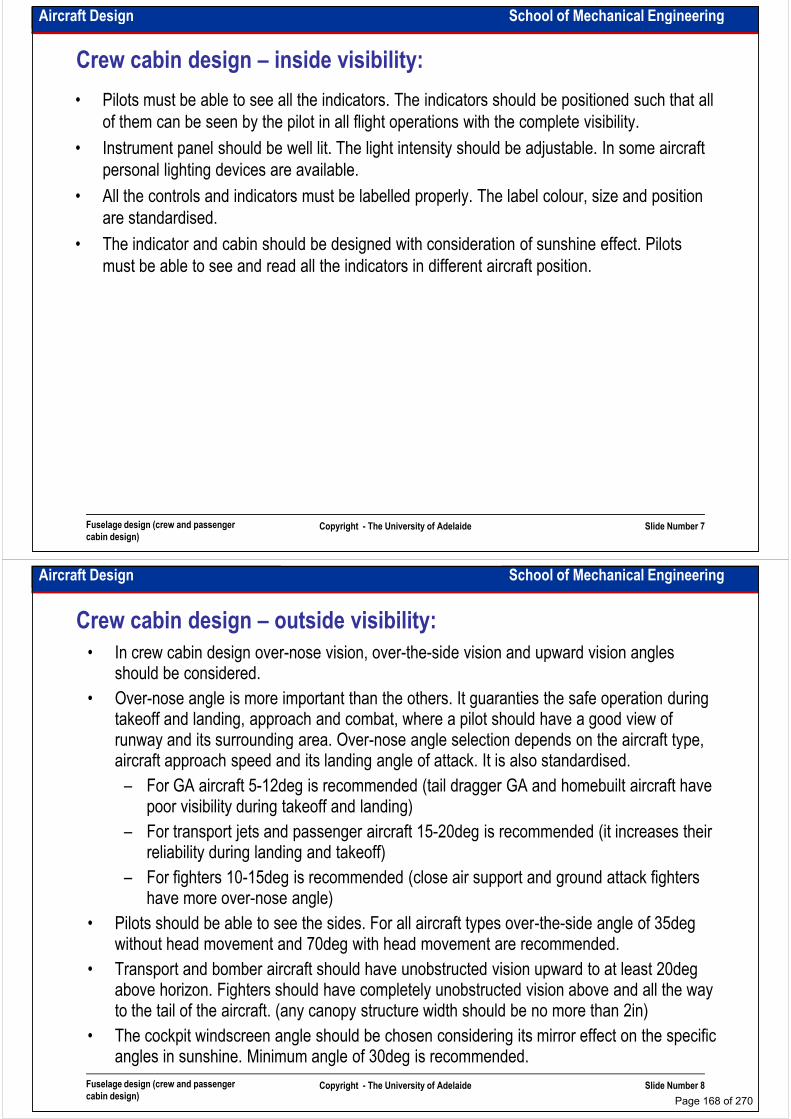
Aircraft Design School of Mechanical Engineering
Crew cabin design – inside visibility:
• Pilots must be able to see all the indicators. The indicators should be positioned such that all
of them can be seen by the pilot in all flight operations with the complete visibility.
• Instrument panel should be well lit. The light intensity should be adjustable. In some aircraft
personal lighting devices are available.
• All the controls and indicators must be labelled properly. The label colour, size and position • All the controls and indicators must be labelled properly. The label colour, size and position
are standardised.
• The indicator and cabin should be designed with consideration of sunshine effect. Pilots
must be able to see and read all the indicators in different aircraft position.
Fuselage design (crew and passenger
cabin design)Copyright - The University of Adelaide Slide Number 7
Aircraft Design School of Mechanical Engineering
Crew cabin design – outside visibility:
• In crew cabin design over-nose vision, over-the-side vision and upward vision angles should be considered.
• Over-nose angle is more important than the others. It guaranties the safe operation during takeoff and landing, approach and combat, where a pilot should have a good view of runway and its surrounding area. Over-nose angle selection depends on the aircraft type, runway and its surrounding area. Over-nose angle selection depends on the aircraft type, aircraft approach speed and its landing angle of attack. It is also standardised.
– For GA aircraft 5-12deg is recommended (tail dragger GA and homebuilt aircraft have poor visibility during takeoff and landing)
– For transport jets and passenger aircraft 15-20deg is recommended (it increases their reliability during landing and takeoff)
– For fighters 10-15deg is recommended (close air support and ground attack fighters have more over-nose angle)
• Pilots should be able to see the sides. For all aircraft types over-the-side angle of 35deg
Fuselage design (crew and passenger
cabin design)Copyright - The University of Adelaide Slide Number 8
• Pilots should be able to see the sides. For all aircraft types over-the-side angle of 35deg without head movement and 70deg with head movement are recommended.
• Transport and bomber aircraft should have unobstructed vision upward to at least 20deg above horizon. Fighters should have completely unobstructed vision above and all the way to the tail of the aircraft. (any canopy structure width should be no more than 2in)
• The cockpit windscreen angle should be chosen considering its mirror effect on the specific angles in sunshine. Minimum angle of 30deg is recommended.
Page 168 of 270
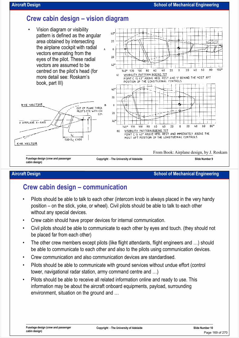
Aircraft Design School of Mechanical Engineering
Crew cabin design – vision diagram
• Vision diagram or visibility pattern is defined as the angular area obtained by intersecting the airplane cockpit with radial vectors emanating from the eyes of the pilot. These radial eyes of the pilot. These radial vectors are assumed to be centred on the pilot’s head (for more detail see: Roskam’s book, part III)
Fuselage design (crew and passenger
cabin design)Copyright - The University of Adelaide Slide Number 9
From Book: Airplane design, by J. Roskam
Aircraft Design School of Mechanical Engineering
Crew cabin design – communication
• Pilots should be able to talk to each other (intercom knob is always placed in the very handy
position – on the stick, yoke, or wheel). Civil pilots should be able to talk to each other
without any special devices.
• Crew cabin should have proper devices for internal communication.
• Civil pilots should be able to communicate to each other by eyes and touch. (they should not • Civil pilots should be able to communicate to each other by eyes and touch. (they should not
be placed far from each other)
• The other crew members except pilots (like flight attendants, flight engineers and …) should
be able to communicate to each other and also to the pilots using communication devices.
• Crew communication and also communication devices are standardised.
• Pilots should be able to communicate with ground services without undue effort (control
tower, navigational radar station, army command centre and …)
• Pilots should be able to receive all related information online and ready to use. This
Fuselage design (crew and passenger
cabin design)Copyright - The University of Adelaide Slide Number 10
• Pilots should be able to receive all related information online and ready to use. This
information may be about the aircraft onboard equipments, payload, surrounding
environment, situation on the ground and …
Page 169 of 270
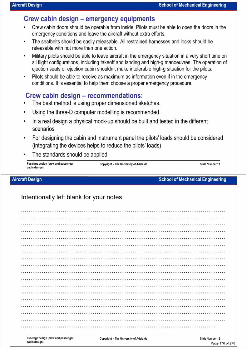
Aircraft Design School of Mechanical Engineering
Crew cabin design – emergency equipments• Crew cabin doors should be operable from inside. Pilots must be able to open the doors in the
emergency conditions and leave the aircraft without extra efforts.
• The seatbelts should be easily releasable. All restrained harnesses and locks should be releasable with not more than one action.
• Military pilots should be able to leave aircraft in the emergency situation in a very short time on • Military pilots should be able to leave aircraft in the emergency situation in a very short time on all flight configurations, including takeoff and landing and high-g manoeuvres. The operation of ejection seats or ejection cabin shouldn’t make intolerable high-g situation for the pilots.
• Pilots should be able to receive as maximum as information even if in the emergency conditions. It is essential to help them choose a proper emergency procedure.
Crew cabin design – recommendations:• The best method is using proper dimensioned sketches.
• Using the three-D computer modelling is recommended.
Fuselage design (crew and passenger
cabin design)Copyright - The University of Adelaide Slide Number 11
• Using the three-D computer modelling is recommended.
• In a real design a physical mock-up should be built and tested in the different
scenarios
• For designing the cabin and instrument panel the pilots’ loads should be considered
(integrating the devices helps to reduce the pilots’ loads)
• The standards should be applied
Aircraft Design School of Mechanical Engineering
Intentionally left blank for your notes
………………………………………………………………………………………………
………………………………………………………………………………………………
………………………………………………………………………………………………
………………………………………………………………………………………………………………………………………………………………………………………………
………………………………………………………………………………………………
………………………………………………………………………………………………
………………………………………………………………………………………………
………………………………………………………………………………………………
………………………………………………………………………………………………
………………………………………………………………………………………………
………………………………………………………………………………………………
………………………………………………………………………………………………
………………………………………………………………………………………………
Fuselage design (crew and passenger
cabin design)Copyright - The University of Adelaide Slide Number 12
………………………………………………………………………………………………
………………………………………………………………………………………………
………………………………………………………………………………………………
………………………………………………………………………………………………
………………………………………………………………………………………………
………………………………………………………………………………………….
Page 170 of 270
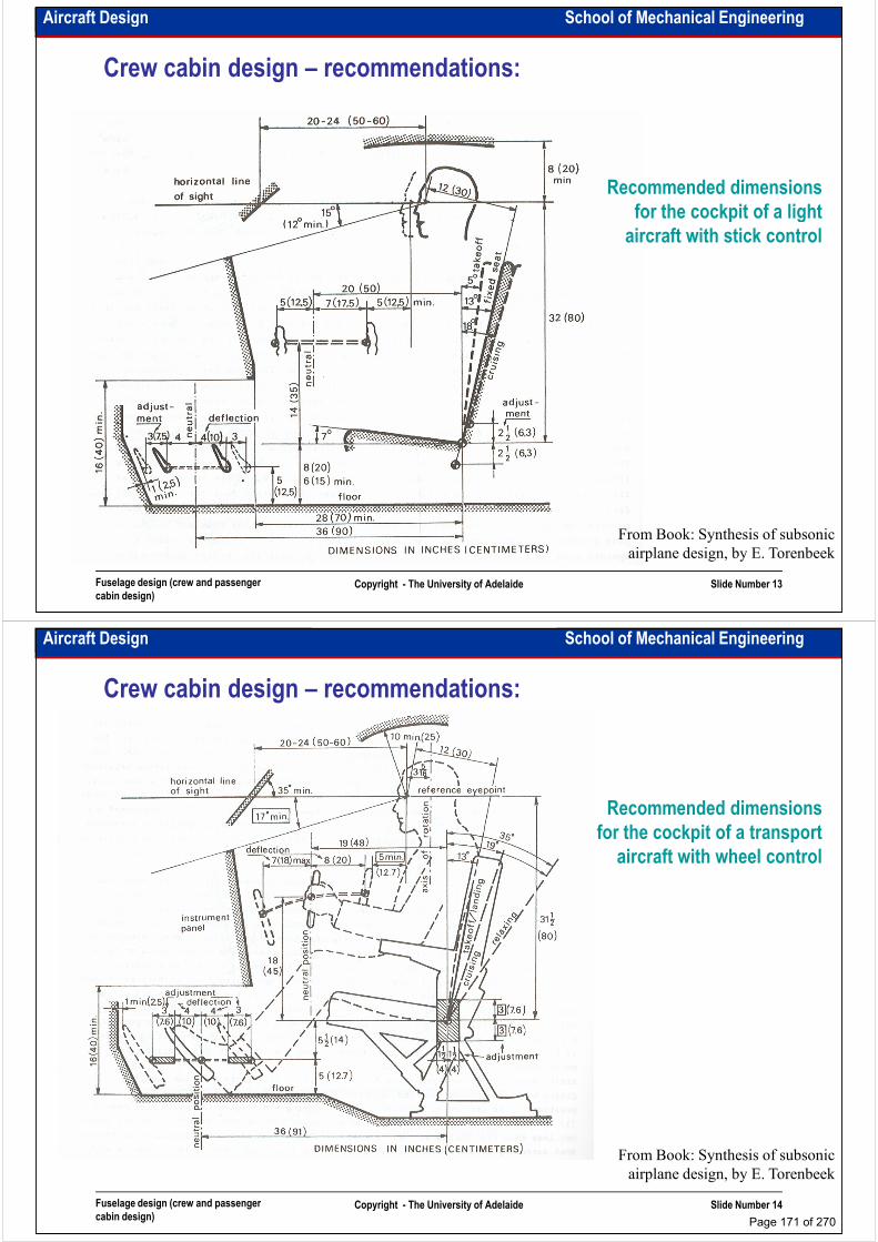
Aircraft Design School of Mechanical Engineering
Crew cabin design – recommendations:
Recommended dimensions
for the cockpit of a light for the cockpit of a light
aircraft with stick control
Fuselage design (crew and passenger
cabin design)Copyright - The University of Adelaide Slide Number 13
From Book: Synthesis of subsonic
airplane design, by E. Torenbeek
Aircraft Design School of Mechanical Engineering
Crew cabin design – recommendations:
Recommended dimensions
for the cockpit of a transport for the cockpit of a transport
aircraft with wheel control
Fuselage design (crew and passenger
cabin design)Copyright - The University of Adelaide Slide Number 14
From Book: Synthesis of subsonic
airplane design, by E. Torenbeek
Page 171 of 270
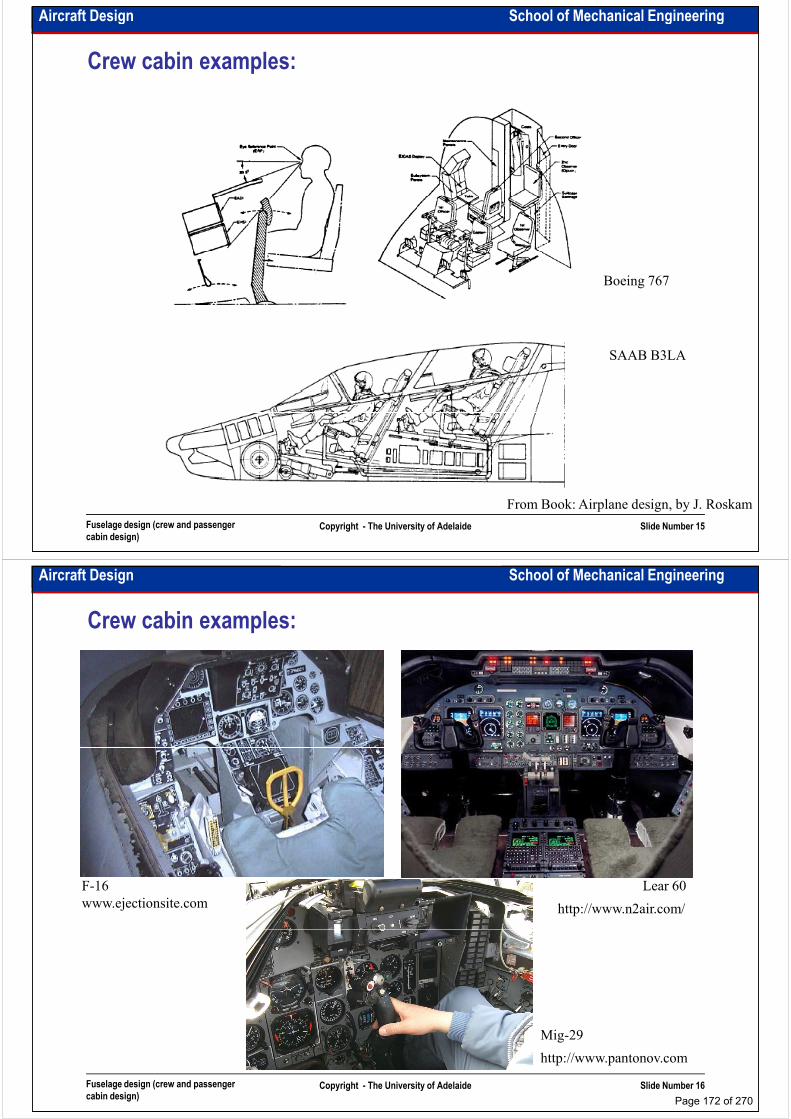
Aircraft Design School of Mechanical Engineering
Crew cabin examples:
Boeing 767
SAAB B3LA
Fuselage design (crew and passenger
cabin design)Copyright - The University of Adelaide Slide Number 15
From Book: Airplane design, by J. Roskam
Aircraft Design School of Mechanical Engineering
Crew cabin examples:
www.ejectionsite.com
F-16 Lear 60
http://www.n2air.com/
Fuselage design (crew and passenger
cabin design)Copyright - The University of Adelaide Slide Number 16
Mig-29
http://www.pantonov.com
Page 172 of 270
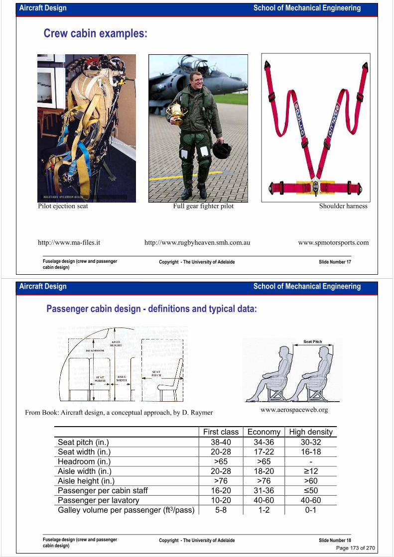
Aircraft Design School of Mechanical Engineering
Crew cabin examples:
Fuselage design (crew and passenger
cabin design)Copyright - The University of Adelaide Slide Number 17
http://www.ma-files.it
Pilot ejection seat Full gear fighter pilot
http://www.rugbyheaven.smh.com.au
Shoulder harness
www.spmotorsports.com
Aircraft Design School of Mechanical Engineering
Passenger cabin design - definitions and typical data:
www.aerospaceweb.org From Book: Aircraft design, a conceptual approach, by D. Raymer
First class Economy High density
Seat pitch (in.) 38-40 34-36 30-32
Seat width (in.) 20-28 17-22 16-18
Headroom (in.) >65 >65 -
Fuselage design (crew and passenger
cabin design)Copyright - The University of Adelaide Slide Number 18
Headroom (in.) >65 >65 -
Aisle width (in.) 20-28 18-20 ≥12
Aisle height (in.) >76 >76 >60
Passenger per cabin staff 16-20 31-36 ≤50
Passenger per lavatory 10-20 40-60 40-60
Galley volume per passenger (ft3/pass) 5-8 1-2 0-1
Page 173 of 270

Aircraft Design School of Mechanical Engineering
Intentionally left blank for your notes
………………………………………………………………………………………………
………………………………………………………………………………………………
………………………………………………………………………………………………
………………………………………………………………………………………………………………………………………………………………………………………………
………………………………………………………………………………………………
………………………………………………………………………………………………
………………………………………………………………………………………………
………………………………………………………………………………………………
………………………………………………………………………………………………
………………………………………………………………………………………………
………………………………………………………………………………………………
………………………………………………………………………………………………
………………………………………………………………………………………………
Fuselage design (crew and passenger
cabin design)Copyright - The University of Adelaide Slide Number 19
………………………………………………………………………………………………
………………………………………………………………………………………………
………………………………………………………………………………………………
………………………………………………………………………………………………
………………………………………………………………………………………………
………………………………………………………………………………………….
Aircraft Design School of Mechanical Engineering
Passenger cabin design – considerations:
• To design a passenger cabin decide which type of cabin you need (first class, economy,
combination, …)
• Consider main doors, emergency exits, lavatory and galley layouts and positions
• Prepare a dimensioned drawing of the cabin
• Internal diameter of fuselage is smaller than its outside diameter. To calculate outside • Internal diameter of fuselage is smaller than its outside diameter. To calculate outside
diameter add 1-4in to internal diameter, depending on aircraft type.
• Weight and dimensions of passengers are standardised. However they are mainly dictated
by transport companies. (Typically passenger average weight can be assumed 180lb with
carry-on bags. Checked luggage weight can be assumed 40-60lb)
• Passenger seats, restraint systems, onboard entertainment facilities and … can be ordered
by transport companies. However all of them should be designed and installed according
the aviation standards.
Fuselage design (crew and passenger
cabin design)Copyright - The University of Adelaide Slide Number 20
• Passenger cabin design and its arrangement are usually done by transport companies.
• Remember that the passengers are the customers and customer is always the main
person. The cabin environment must not be boring. Passengers should be able to eat,
drink, sleep, read and enjoy in the cabin at their seats
Page 174 of 270

Aircraft Design School of Mechanical Engineering
Passenger cabin – layout example:
Fuselage design (crew and passenger
cabin design)Copyright - The University of Adelaide Slide Number 21
http://www.aerospaceweb.org
Aircraft Design School of Mechanical Engineering
Passenger cabin – cross section example:
Fuselage design (crew and passenger
cabin design)Copyright - The University of Adelaide Slide Number 22
From Book: Airplane design, by J. Roskam
Page 175 of 270
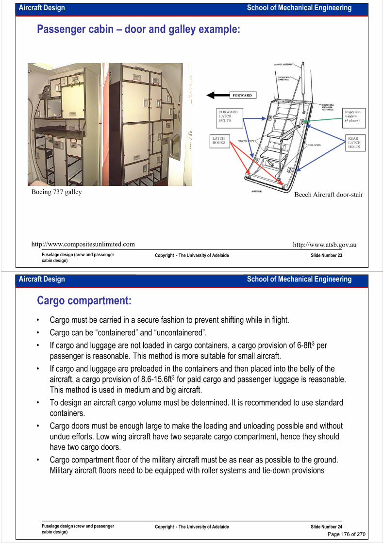
Aircraft Design School of Mechanical Engineering
Passenger cabin – door and galley example:
Fuselage design (crew and passenger
cabin design)Copyright - The University of Adelaide Slide Number 23
http://www.atsb.gov.au
Beech Aircraft door-stair Boeing 737 galley
http://www.compositesunlimited.com
Aircraft Design School of Mechanical Engineering
Cargo compartment:
• Cargo must be carried in a secure fashion to prevent shifting while in flight.
• Cargo can be “containered” and “uncontainered”.
• If cargo and luggage are not loaded in cargo containers, a cargo provision of 6-8ft3 per
passenger is reasonable. This method is more suitable for small aircraft.
• If cargo and luggage are preloaded in the containers and then placed into the belly of the
aircraft, a cargo provision of 8.6-15.6ft3 for paid cargo and passenger luggage is reasonable.
This method is used in medium and big aircraft.
• To design an aircraft cargo volume must be determined. It is recommended to use standard
containers.
• Cargo doors must be enough large to make the loading and unloading possible and without
undue efforts. Low wing aircraft have two separate cargo compartment, hence they should
have two cargo doors.
Fuselage design (crew and passenger
cabin design)Copyright - The University of Adelaide Slide Number 24
have two cargo doors.
• Cargo compartment floor of the military aircraft must be as near as possible to the ground.
Military aircraft floors need to be equipped with roller systems and tie-down provisions
Page 176 of 270

Aircraft Design School of Mechanical Engineering
Cargo compartment – standard containers:
Fuselage design (crew and passenger
cabin design)Copyright - The University of Adelaide Slide Number 25
From Book: Airplane design, by J. Roskam
Aircraft Design School of Mechanical Engineering
Standard container sizes and capacity
Type Length
(cm)
Width (cm) Height
(cm)
Base
length (cm)
Capacity
(kg)
Volume
(m3)
LD1 228.0 145.0 162.6 147.0 1588 4.80
LD2 156.2 153.4 162.6 119.2 1225 3.40LD2 156.2 153.4 162.6 119.2 1225 3.40
LD3 200.7 153.4 162.6 156.2 1588 4.80
LD4 244.0 153.4 162.6 244.0 2450 6.10
LD6 406.4 153.4 162.6 317.5 3175 8.80
LD7 317.5 223.5 162.5 317.5 4627 9.91
LD8 317.5 153.4 162.5 243.8 2449 6.94
Fuselage design (crew and passenger
cabin design)Copyright - The University of Adelaide Slide Number 26
LD11 307.0 145.0 162.5 307.0 3176 7.00
LD26 400.0 214.0 162.5 307.0 6033 12.00
M1 318.0 224.0 224.0 318.0 6804 17.58
PGA Pallet 608.0 244.0 244.0 608.0 11340 36.20
Page 177 of 270
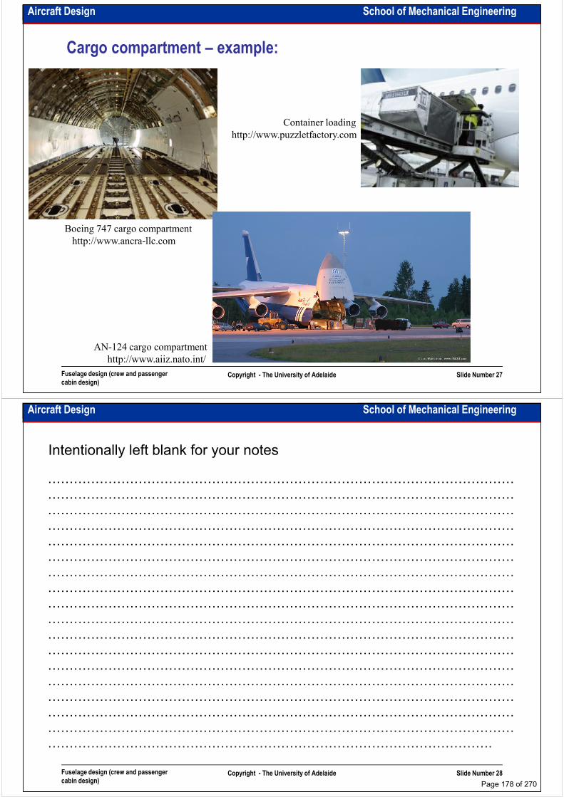
Aircraft Design School of Mechanical Engineering
Cargo compartment – example:
http://www.puzzletfactory.com
Container loading
Boeing 747 cargo compartment
http://www.ancra-llc.com
http://www.puzzletfactory.com
Fuselage design (crew and passenger
cabin design)Copyright - The University of Adelaide Slide Number 27
http://www.aiiz.nato.int/
AN-124 cargo compartment
Aircraft Design School of Mechanical Engineering
Intentionally left blank for your notes
………………………………………………………………………………………………
………………………………………………………………………………………………
………………………………………………………………………………………………
………………………………………………………………………………………………………………………………………………………………………………………………
………………………………………………………………………………………………
………………………………………………………………………………………………
………………………………………………………………………………………………
………………………………………………………………………………………………
………………………………………………………………………………………………
………………………………………………………………………………………………
………………………………………………………………………………………………
………………………………………………………………………………………………
………………………………………………………………………………………………
Fuselage design (crew and passenger
cabin design)Copyright - The University of Adelaide Slide Number 28
………………………………………………………………………………………………
………………………………………………………………………………………………
………………………………………………………………………………………………
………………………………………………………………………………………………
………………………………………………………………………………………………
………………………………………………………………………………………….
Page 178 of 270

School of Mechanical EngineeringAircraft Design
Fuselage design (overall configuration)
Dr. MAZIAR ARJOMANDI
Semester I
Fuselage design (overall configuration) Copyright - The University of Adelaide Slide Number 1
Semester I
Aircraft Design School of Mechanical Engineering
Aerodynamic considerations – friction drag:
• It is directly proportional to wetted area.
• To reduce friction drag two options are available: a) shape the fuselage so that the
laminar flow is possible; b) reduce the length and perimeter as much as possible.
• Too tight packaging should be avoided for maintainability considerations.
• A short fat fuselage has a short tail moment arm which increases the required tail area.• A short fat fuselage has a short tail moment arm which increases the required tail area.
• When the length and diameter are calculated, exterior roughness and nose shape should
be considered as they can determine the extent of laminar flow which can be achieved
(Most fuselage body have a turbulent boundary layer with correspondingly high friction).
• Fuselage fineness ratio is fuselage length divided by fuselage diameter or:
, , , f
fN
fN
f
fC
fC
f
f
fD
L
D
L
D
L=== λλλ
Fuselage design (overall configuration) Copyright - The University of Adelaide Slide Number 2
length cone fuselage is and length nose fuselage is :where fNfC
fff
LL
Page 179 of 270

Aircraft Design School of Mechanical Engineering
Aerodynamic considerations – friction drag:
llllfnFuselage parameters recommendations
(for more detail see Roskam’s book, Vol 2)Fuselage parameters
(for more detail see Roskam’s book, Vol 2)
M≤0.7 M=0.8-0.9 M≥1
λλλλF 6-9 8-13 10-23
λλλλFN 1.2-2 1.7-2.5 4-6
λλλλFC 2-3 3-4 5-7
Fuselage design (overall configuration) Copyright - The University of Adelaide Slide Number 3
Effect of fineness ratio on fuselage drag
From Book: Airplane design, by J. Roskam
Aircraft Design School of Mechanical Engineering
Intentionally left blank for your notes
………………………………………………………………………………………………
………………………………………………………………………………………………
………………………………………………………………………………………………
………………………………………………………………………………………………………………………………………………………………………………………………
………………………………………………………………………………………………
………………………………………………………………………………………………
………………………………………………………………………………………………
………………………………………………………………………………………………
………………………………………………………………………………………………
………………………………………………………………………………………………
………………………………………………………………………………………………
………………………………………………………………………………………………
………………………………………………………………………………………………
Fuselage design (overall configuration) Copyright - The University of Adelaide Slide Number 4
………………………………………………………………………………………………
………………………………………………………………………………………………
………………………………………………………………………………………………
………………………………………………………………………………………………
………………………………………………………………………………………………
………………………………………………………………………………………….
Page 180 of 270
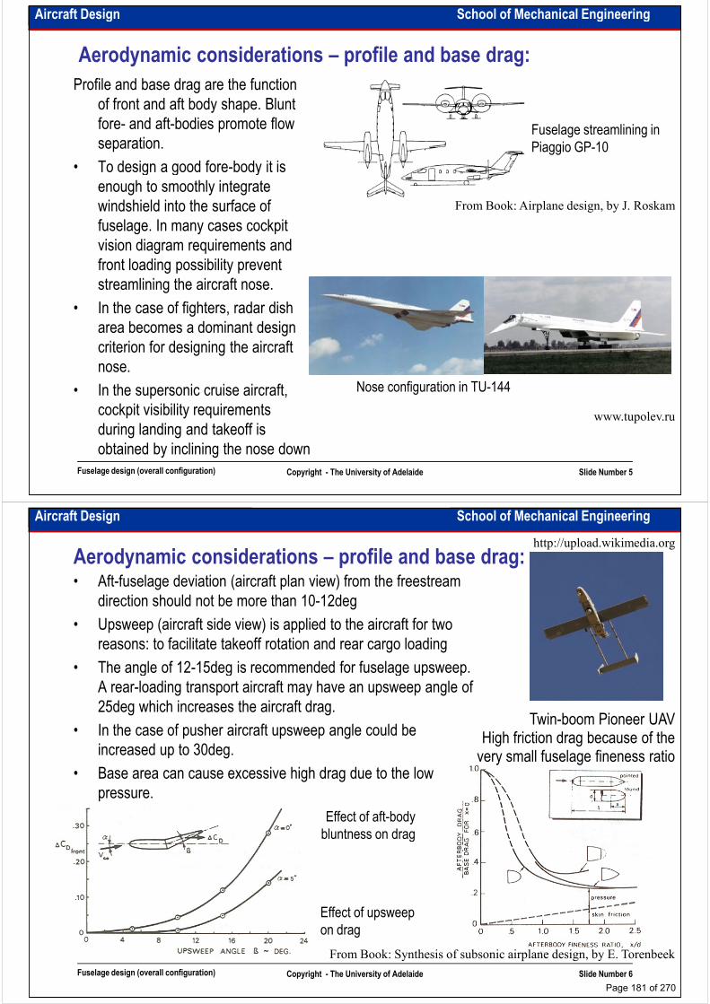
Aircraft Design School of Mechanical Engineering
Aerodynamic considerations – profile and base drag:
Profile and base drag are the function
of front and aft body shape. Blunt
fore- and aft-bodies promote flow
separation.
• To design a good fore-body it is
Fuselage streamlining in
Piaggio GP-10
• To design a good fore-body it is
enough to smoothly integrate
windshield into the surface of
fuselage. In many cases cockpit
vision diagram requirements and
front loading possibility prevent
streamlining the aircraft nose.
• In the case of fighters, radar dish
area becomes a dominant design
From Book: Airplane design, by J. Roskam
Fuselage design (overall configuration) Copyright - The University of Adelaide Slide Number 5
area becomes a dominant design
criterion for designing the aircraft
nose.
• In the supersonic cruise aircraft,
cockpit visibility requirements
during landing and takeoff is
obtained by inclining the nose down
www.tupolev.ru
Nose configuration in TU-144
Aircraft Design School of Mechanical Engineering
Aerodynamic considerations – profile and base drag:• Aft-fuselage deviation (aircraft plan view) from the freestream
direction should not be more than 10-12deg
• Upsweep (aircraft side view) is applied to the aircraft for two
reasons: to facilitate takeoff rotation and rear cargo loading
• The angle of 12-15deg is recommended for fuselage upsweep.
http://upload.wikimedia.org
Effect of aft-body
bluntness on drag
• The angle of 12-15deg is recommended for fuselage upsweep.
A rear-loading transport aircraft may have an upsweep angle of
25deg which increases the aircraft drag.
• In the case of pusher aircraft upsweep angle could be
increased up to 30deg.
• Base area can cause excessive high drag due to the low
pressure.
Twin-boom Pioneer UAVHigh friction drag because of the
very small fuselage fineness ratio
Fuselage design (overall configuration) Copyright - The University of Adelaide Slide Number 6
bluntness on drag
Effect of upsweep
on drag
From Book: Synthesis of subsonic airplane design, by E. Torenbeek
Page 181 of 270
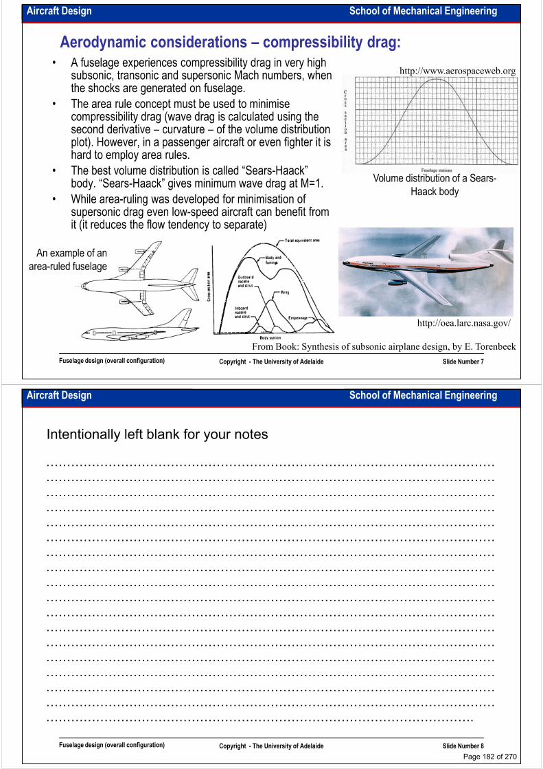
Aircraft Design School of Mechanical Engineering
Aerodynamic considerations – compressibility drag:• A fuselage experiences compressibility drag in very high
subsonic, transonic and supersonic Mach numbers, when the shocks are generated on fuselage.
• The area rule concept must be used to minimise compressibility drag (wave drag is calculated using the second derivative – curvature – of the volume distribution
http://www.aerospaceweb.org
second derivative – curvature – of the volume distribution plot). However, in a passenger aircraft or even fighter it is hard to employ area rules.
• The best volume distribution is called “Sears-Haack” body. “Sears-Haack” gives minimum wave drag at M=1.
• While area-ruling was developed for minimisation of supersonic drag even low-speed aircraft can benefit from it (it reduces the flow tendency to separate)
An example of an
Volume distribution of a Sears-
Haack body
Fuselage design (overall configuration) Copyright - The University of Adelaide Slide Number 7
From Book: Synthesis of subsonic airplane design, by E. Torenbeek
An example of an
area-ruled fuselage
http://oea.larc.nasa.gov/
Aircraft Design School of Mechanical Engineering
Intentionally left blank for your notes
………………………………………………………………………………………………
………………………………………………………………………………………………
………………………………………………………………………………………………
………………………………………………………………………………………………………………………………………………………………………………………………
………………………………………………………………………………………………
………………………………………………………………………………………………
………………………………………………………………………………………………
………………………………………………………………………………………………
………………………………………………………………………………………………
………………………………………………………………………………………………
………………………………………………………………………………………………
………………………………………………………………………………………………
………………………………………………………………………………………………
Fuselage design (overall configuration) Copyright - The University of Adelaide Slide Number 8
………………………………………………………………………………………………
………………………………………………………………………………………………
………………………………………………………………………………………………
………………………………………………………………………………………………
………………………………………………………………………………………………
………………………………………………………………………………………….
Page 182 of 270
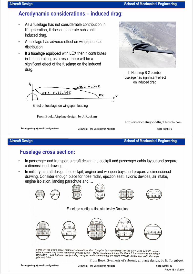
Aircraft Design School of Mechanical Engineering
Aerodynamic considerations – induced drag:
• As a fuselage has not considerable contribution in
lift generation, it doesn’t generate substantial
induced drag.
• A fuselage has adverse effect on wingspan load
distributiondistribution
• If a fuselage equipped with LEX then it contributes
in lift generating, as a result there will be a
significant effect of the fuselage on the induced
drag.In Northrop B-2 bomber
fuselage has significant effect
on induced drag
Fuselage design (overall configuration) Copyright - The University of Adelaide Slide Number 9
From Book: Airplane design, by J. Roskam
Effect of fuselage on wingspan loading
http://www.century-of-flight.freeola.com
Aircraft Design School of Mechanical Engineering
Fuselage cross section:
• In passenger and transport aircraft design the cockpit and passenger cabin layout and prepare a dimensioned drawing.
• In military aircraft design the cockpit, engine and weapon bays and prepare a dimensioned drawing. Consider enough place for nose radar, ejection seat, avionic devices, air intake, engine isolation, landing parachute and …
Fuselage configuration studies by Douglas
engine isolation, landing parachute and …
Fuselage design (overall configuration) Copyright - The University of Adelaide Slide Number 10
From Book: Synthesis of subsonic airplane design, by E. Torenbeek
Page 183 of 270

Aircraft Design School of Mechanical Engineering
Fuselage cross section - example:
Fuselage design (overall configuration) Copyright - The University of Adelaide Slide Number 11
From Book: Synthesis of subsonic airplane design, by E. Torenbeek
Cabin arrangement of DC-10 A good fuselage cross section drawing
For more example see Roskam’s Book, vol. 3
Aircraft Design School of Mechanical Engineering
Intentionally left blank for your notes
………………………………………………………………………………………………
………………………………………………………………………………………………
………………………………………………………………………………………………
………………………………………………………………………………………………………………………………………………………………………………………………
………………………………………………………………………………………………
………………………………………………………………………………………………
………………………………………………………………………………………………
………………………………………………………………………………………………
………………………………………………………………………………………………
………………………………………………………………………………………………
………………………………………………………………………………………………
………………………………………………………………………………………………
………………………………………………………………………………………………
Fuselage design (overall configuration) Copyright - The University of Adelaide Slide Number 12
………………………………………………………………………………………………
………………………………………………………………………………………………
………………………………………………………………………………………………
………………………………………………………………………………………………
………………………………………………………………………………………………
………………………………………………………………………………………….
Page 184 of 270
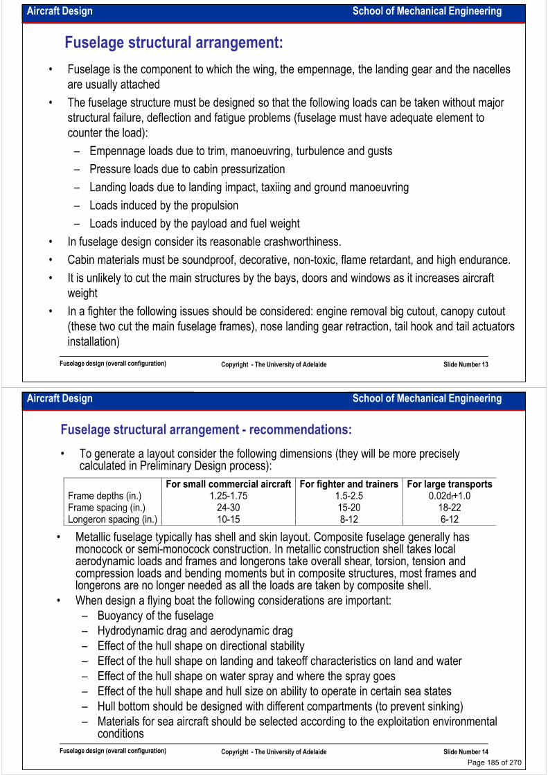
Aircraft Design School of Mechanical Engineering
Fuselage structural arrangement:
• Fuselage is the component to which the wing, the empennage, the landing gear and the nacelles
are usually attached
• The fuselage structure must be designed so that the following loads can be taken without major
structural failure, deflection and fatigue problems (fuselage must have adequate element to
counter the load):counter the load):
– Empennage loads due to trim, manoeuvring, turbulence and gusts
– Pressure loads due to cabin pressurization
– Landing loads due to landing impact, taxiing and ground manoeuvring
– Loads induced by the propulsion
– Loads induced by the payload and fuel weight
• In fuselage design consider its reasonable crashworthiness.
• Cabin materials must be soundproof, decorative, non-toxic, flame retardant, and high endurance.
Fuselage design (overall configuration) Copyright - The University of Adelaide Slide Number 13
• Cabin materials must be soundproof, decorative, non-toxic, flame retardant, and high endurance.
• It is unlikely to cut the main structures by the bays, doors and windows as it increases aircraft
weight
• In a fighter the following issues should be considered: engine removal big cutout, canopy cutout
(these two cut the main fuselage frames), nose landing gear retraction, tail hook and tail actuators
installation)
Aircraft Design School of Mechanical Engineering
Fuselage structural arrangement - recommendations:
• To generate a layout consider the following dimensions (they will be more precisely calculated in Preliminary Design process):
For small commercial aircraft For fighter and trainers For large transports Frame depths (in.) 1.25-1.75 1.5-2.5 0.02df+1.0 Frame spacing (in.) 24-30 15-20 18-22 Longeron spacing (in.) 10-15 8-12 6-12 Longeron spacing (in.) 10-15 8-12 6-12
• Metallic fuselage typically has shell and skin layout. Composite fuselage generally has monocock or semi-monocock construction. In metallic construction shell takes local aerodynamic loads and frames and longerons take overall shear, torsion, tension and compression loads and bending moments but in composite structures, most frames and longerons are no longer needed as all the loads are taken by composite shell.
• When design a flying boat the following considerations are important:
– Buoyancy of the fuselage
– Hydrodynamic drag and aerodynamic drag
– Effect of the hull shape on directional stability
Fuselage design (overall configuration) Copyright - The University of Adelaide Slide Number 14
– Effect of the hull shape on directional stability
– Effect of the hull shape on landing and takeoff characteristics on land and water
– Effect of the hull shape on water spray and where the spray goes
– Effect of the hull shape and hull size on ability to operate in certain sea states
– Hull bottom should be designed with different compartments (to prevent sinking)
– Materials for sea aircraft should be selected according to the exploitation environmental conditions
Page 185 of 270

Aircraft Design School of Mechanical Engineering
Fuselage structural arrangement - seaplane:
Parts of a seaplane haul
Seaplane spray pattern
Seaplane fuselage cross section
Fuselage design (overall configuration) Copyright - The University of Adelaide Slide Number 15
From Book: The anatomy of the airplane, by D. Stinton
Aircraft Design School of Mechanical Engineering
Fuselage structural arrangement - examples:
Structural arrangement for Douglas A4D-2N Skyhawk
Fuselage design (overall configuration) Copyright - The University of Adelaide Slide Number 16
From Book: Airplane design, by J. Roskam
Page 186 of 270

Aircraft Design School of Mechanical Engineering
Fuselage structural arrangement - examples:
Fuselage shell and
structural arrangement
for the McDonnel
Douglas DC10
Fuselage design (overall configuration) Copyright - The University of Adelaide Slide Number 17
From Book: Airplane design, by J. Roskam
Aircraft Design School of Mechanical Engineering
Fuselage layout - examples:
Fuselage design (overall configuration) Copyright - The University of Adelaide Slide Number 18
From Airbus Industry brochures
Page 187 of 270
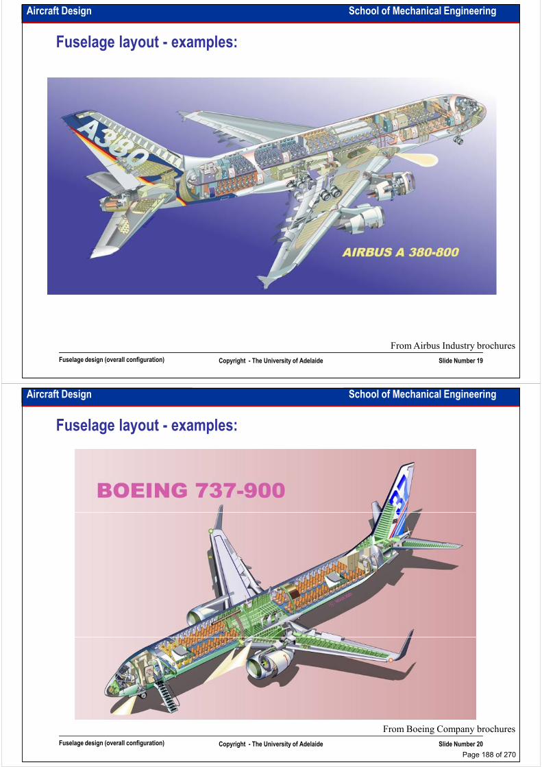
Aircraft Design School of Mechanical Engineering
Fuselage layout - examples:
Fuselage design (overall configuration) Copyright - The University of Adelaide Slide Number 19
From Airbus Industry brochures
Aircraft Design School of Mechanical Engineering
Fuselage layout - examples:
Fuselage design (overall configuration) Copyright - The University of Adelaide Slide Number 20
From Boeing Company brochures
Page 188 of 270

Aircraft Design School of Mechanical Engineering
Fuselage layout - examples:
Fuselage design (overall configuration) Copyright - The University of Adelaide Slide Number 21
From Dassault Company brochures
Aircraft Design School of Mechanical Engineering
Fuselage layout - examples:
Fuselage design (overall configuration) Copyright - The University of Adelaide Slide Number 22
From Socata Company brochures
Page 189 of 270
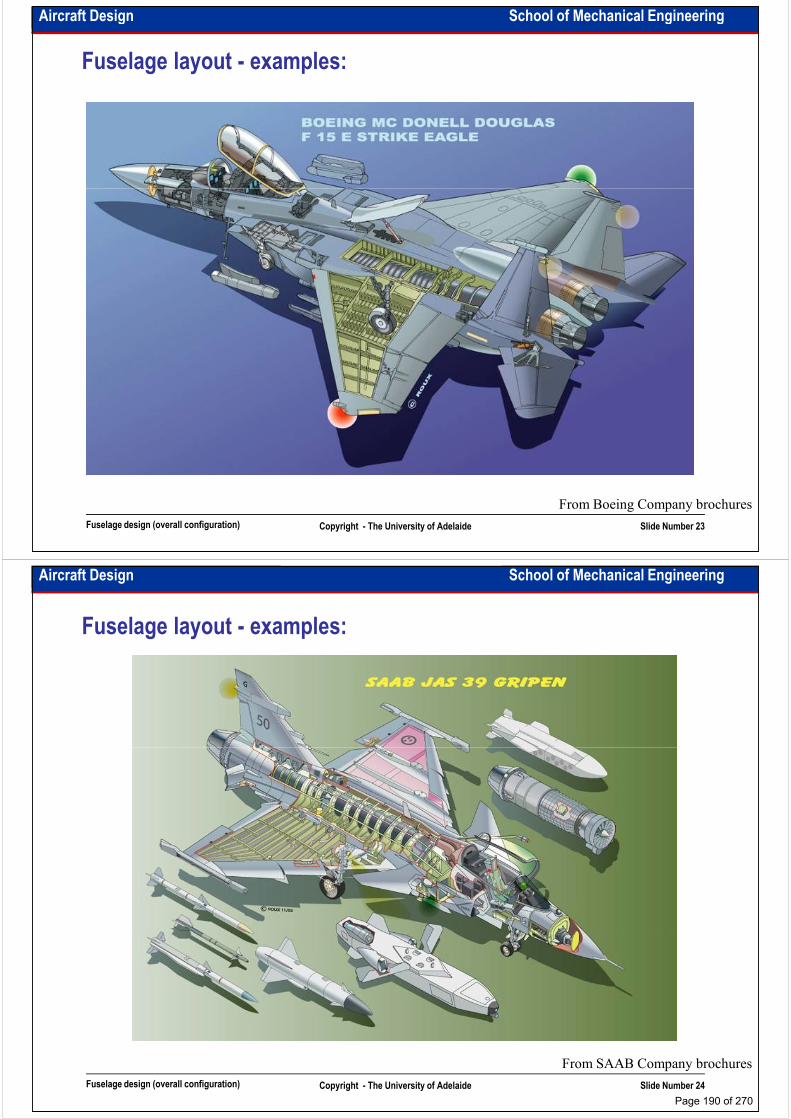
Aircraft Design School of Mechanical Engineering
Fuselage layout - examples:
Fuselage design (overall configuration) Copyright - The University of Adelaide Slide Number 23
From Boeing Company brochures
Aircraft Design School of Mechanical Engineering
Fuselage layout - examples:
Fuselage design (overall configuration) Copyright - The University of Adelaide Slide Number 24
From SAAB Company brochures
Page 190 of 270

Aircraft Design School of Mechanical Engineering
Fuselage layout - examples:
Fuselage design (overall configuration) Copyright - The University of Adelaide Slide Number 25
From Sukhoi Company brochures
Aircraft Design School of Mechanical Engineering
Intentionally left blank for your notes
………………………………………………………………………………………………
………………………………………………………………………………………………
………………………………………………………………………………………………
………………………………………………………………………………………………………………………………………………………………………………………………
………………………………………………………………………………………………
………………………………………………………………………………………………
………………………………………………………………………………………………
………………………………………………………………………………………………
………………………………………………………………………………………………
………………………………………………………………………………………………
………………………………………………………………………………………………
………………………………………………………………………………………………
………………………………………………………………………………………………
Fuselage design (overall configuration) Copyright - The University of Adelaide Slide Number 26
………………………………………………………………………………………………
………………………………………………………………………………………………
………………………………………………………………………………………………
………………………………………………………………………………………………
………………………………………………………………………………………………
………………………………………………………………………………………….
Page 191 of 270

School of Mechanical EngineeringAircraft Design
Propulsion system selection and integration I
Dr. MAZIAR ARJOMANDI
Semester I
Propulsion system selection and integration I Copyright - The University of Adelaide Slide Number 1
Semester I
Aircraft Design School of Mechanical Engineering
Propulsion system selection criteria:
To select a propulsion system the following
factors should be considered:
– Max Cruise Speed
– Operational Ceiling
– Fuel efficiency– Fuel efficiency
– Installed Thrust vs. Dry
– Installed weight vs. Dry weight
– Engine Failure & Safety record
– Cost of acquisition
– Cost of maintenance
• MTBF (Mean Time Between Failure) Propulsion system types
Propulsion system selection and integration I Copyright - The University of Adelaide Slide Number 2
• MTBO (Mean Time Between Overhaul)
– Environmental Regulations
– Availability
– Manoeuvres (Fuel system & Intake)
Propulsion system types
(for detail see Aeronautical Engineering I)
From Book: Aircraft design, a conceptual approach, by D. Raymer
Page 192 of 270
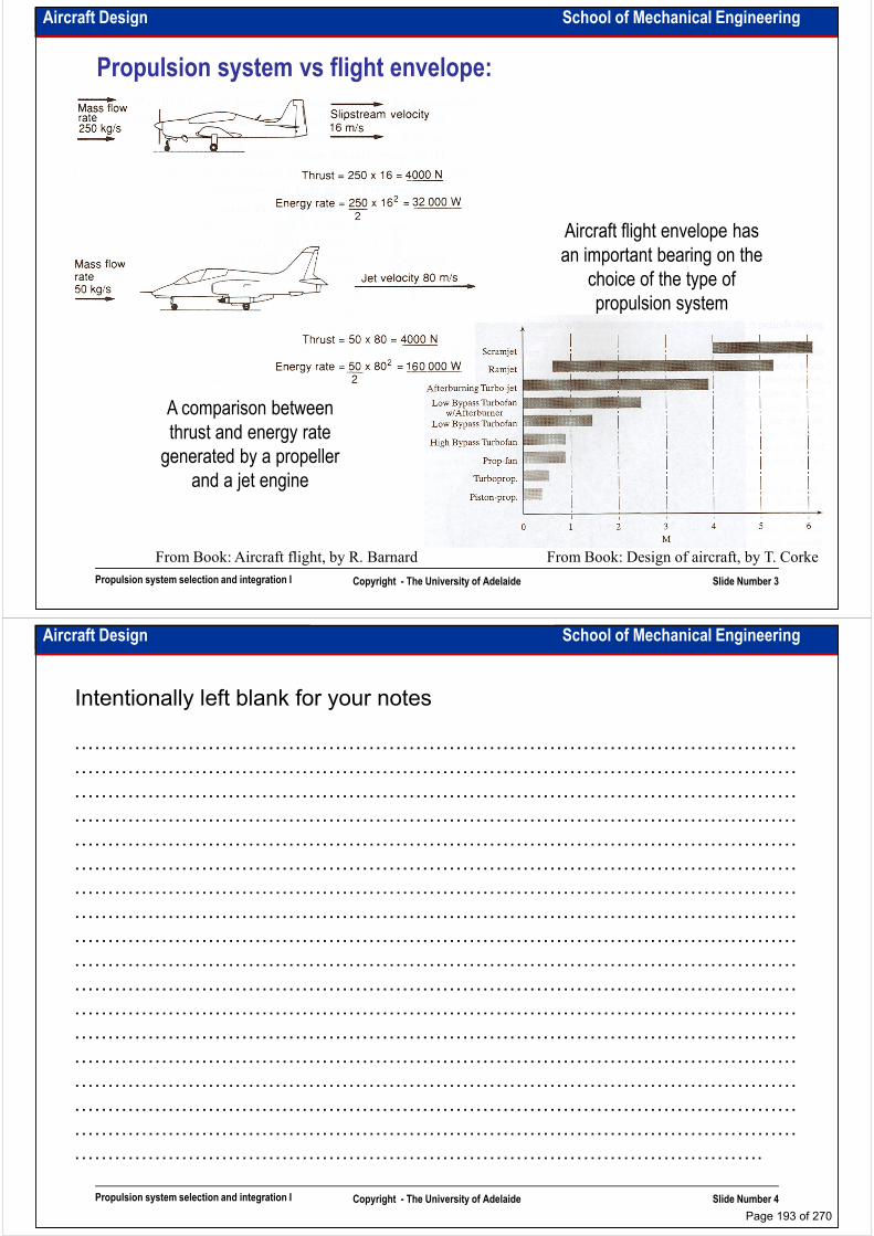
Aircraft Design School of Mechanical Engineering
Propulsion system vs flight envelope:
Aircraft flight envelope has an important bearing on the
choice of the type of propulsion system
A comparison between
Propulsion system selection and integration I Copyright - The University of Adelaide Slide Number 3
From Book: Design of aircraft, by T. Corke
A comparison between thrust and energy rate generated by a propeller
and a jet engine
From Book: Aircraft flight, by R. Barnard
Aircraft Design School of Mechanical Engineering
Intentionally left blank for your notes
………………………………………………………………………………………………
………………………………………………………………………………………………
………………………………………………………………………………………………
………………………………………………………………………………………………………………………………………………………………………………………………
………………………………………………………………………………………………
………………………………………………………………………………………………
………………………………………………………………………………………………
………………………………………………………………………………………………
………………………………………………………………………………………………
………………………………………………………………………………………………
………………………………………………………………………………………………
………………………………………………………………………………………………
………………………………………………………………………………………………
Propulsion system selection and integration I Copyright - The University of Adelaide Slide Number 4
………………………………………………………………………………………………
………………………………………………………………………………………………
………………………………………………………………………………………………
………………………………………………………………………………………………
………………………………………………………………………………………………
………………………………………………………………………………………….
Page 193 of 270

Aircraft Design School of Mechanical Engineering
Propulsion system SFC:
Typical SFC (Specific Fuel Consumption) values associated with different powerplants across
the Mach range
Propulsion system selection and integration I Copyright - The University of Adelaide Slide Number 5
From Book: Airplane design, by J. Roskam
Typical SFC for subsonic engines
http://www.aero-space.nasa.gov/
Aircraft Design School of Mechanical Engineering
Propulsion system thrust and SFC:
• The installed engine thrust is always less than that of uninstalled. The reasons are:
– The manufacturer’s uninstalled engine thrust is obtained with the assumption of full inlet recovery (on assumption of full inlet recovery (on supersonic speeds the installed engine inlet recovery equals to 92-96% of uninstalled engine inlet recovery).
– Manufacturer’s nozzle is more efficient than actual nozzle.
– All the engines have a setting in which they can work with the
Propulsion system selection and integration I Copyright - The University of Adelaide Slide Number 6
From Book: Airplane design, by J. Roskam
Thrust loses vs hight and Mach number for TFE731-1042
which they can work with the minimum value of SFC.
– Part of thrust/power does not contribute in accelerating the aircraft and is used for other purposes
Page 194 of 270
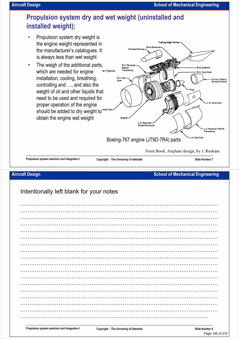
Aircraft Design School of Mechanical Engineering
Propulsion system dry and wet weight (uninstalled and
installed weight):
• Propulsion system dry weight is the engine weight represented in the manufacturer’s catalogues. It is always less than wet weightis always less than wet weight
• The weigh of the additional parts, which are needed for engine installation, cooling, breathing, controlling and …, and also the weight of oil and other liquids that need to be used and required for proper operation of the engine should be added to dry weight to
Propulsion system selection and integration I Copyright - The University of Adelaide Slide Number 7
should be added to dry weight to obtain the engine wet weight
From Book: Airplane design, by J. Roskam
Boeing-767 engine (JT9D-7R4) parts
Aircraft Design School of Mechanical Engineering
Intentionally left blank for your notes
………………………………………………………………………………………………
………………………………………………………………………………………………
………………………………………………………………………………………………
………………………………………………………………………………………………………………………………………………………………………………………………
………………………………………………………………………………………………
………………………………………………………………………………………………
………………………………………………………………………………………………
………………………………………………………………………………………………
………………………………………………………………………………………………
………………………………………………………………………………………………
………………………………………………………………………………………………
………………………………………………………………………………………………
………………………………………………………………………………………………
Propulsion system selection and integration I Copyright - The University of Adelaide Slide Number 8
………………………………………………………………………………………………
………………………………………………………………………………………………
………………………………………………………………………………………………
………………………………………………………………………………………………
………………………………………………………………………………………………
………………………………………………………………………………………….
Page 195 of 270

Aircraft Design School of Mechanical Engineering
Propulsion system cost:
• To buy an engine the following parameters should be considered:
– BEC (Bare Engine Cost)
– Maintenance cost
• MTBF (Mean Time Between Failure). MTBF is found by statistical analysis and shows the reliability of the engine (e.g. 3 failure in 100,000 FH (Flight Hours)shows the reliability of the engine (e.g. 3 failure in 100,000 FH (Flight Hours)
• MTBO (Mean Time between Overhaul). MTBO shows the planned maintenance requirement
• Some engines cost less but have very limited time between overhauls. It means that they have higher maintenance cost.
• Engine manufacturers try to increase MTBO to reduce maintenance cost.
• Accessibility and on-wing maintainability reduce the maintenances cost.
Engine Aircraft Type(s)
Thrust Bypass Ratio
MTBO Average Cost of Overhaul
Market cost (BEC)
Engines in Service
Propulsion system selection and integration I Copyright - The University of Adelaide Slide Number 9
Type(s) Ratio of Overhaul (BEC) Service V2500-A1 A320-200 25,000 lbf 5.4 9,000 FH $2,200,000 $3,724,000
280 engines
V2527-A5 A320-200 26,500 lbf 4.8 15,000 FH $2,000,000 $4,660,000
558 engines
CF6-80C2B1F
747-400 57,900 lbf 5.15 18,000 FH $2,000,000 $4,857,000
1,024 engines
AL-31F Su-27 1,000 hours
Aircraft Design School of Mechanical Engineering
Propulsion system environmental regulations:
• Mainly they are two:1. Engine emissions2. Engine noise
• Environmental effects of the engines are regulated by ICAOregulated by ICAO
Propulsion system selection and integration I Copyright - The University of Adelaide Slide Number 10
http://www.aero-space.nasa.gov/
http://www.icao.int/ttp://www.techtransfer.berkeley.edu
Page 196 of 270

Aircraft Design School of Mechanical Engineering
Propulsion system – aircraft manoeuvres:
• The aircraft propulsion systems have work limitation in high angle of attacks and high-g manoeuvres. It is mainly related to the fuel and lubrication systems
• In GA and UAV where the main fuel delivery systems work by the gravity force, for manoeuvrability (e.g. inverse flight) we need to have central fuel tank
• In some fighters and full acrobatic aircraft fuel system should be pressurised• In some fighters and full acrobatic aircraft fuel system should be pressurised
• Almost all the aircraft have limitation in reverse flight
• Fuel lines and tanks have quite a large number of barrier and check valves, which prevent fuel movements and guarantee the fuel delivery in all flight configurations.
Propulsion system selection and integration I Copyright - The University of Adelaide Slide Number 11
Aircraft Design School of Mechanical Engineering
Thrust calculation (Jet engines):
• In jet engines thrust is reduced when the flight altitude and speed are increased. If an aircraft is being sized based on the thrust required for cruise, the sea level thrust for that cruise speed needs to be corrected for altitude and temperature.
• To find out how thrust changes with the air velocity, altitude and temperature, it is recommended to use manufacturer’s data.recommended to use manufacturer’s data.
• The main equation for turbojet engine thrust calculation is:
• The air density is a function of the pressure and temperature, therefore if no data are available the thrust at the elevation and temperature can be calculated by:
( ) ( ).conditionsexit -jet andc atmospheri to refer and
pressure, is velocity, is rate, flow mass is : where
ea
PVmPPAVVmT aeeaeɺɺ −+−=
ρ
Propulsion system selection and integration I Copyright - The University of Adelaide Slide Number 12
ref
refTTρρ
ρ =
Page 197 of 270
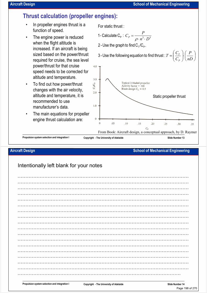
Aircraft Design School of Mechanical Engineering
Thrust calculation (propeller engines):
• In propeller engines thrust is a function of speed.
• The engine power is reduced when the flight altitude is increased. If an aircraft is being
⋅⋅=
Dn
PCP
./CC find to graph the Use -2
:C Calculate -1
:thruststatic For
PT
P 53ρ
increased. If an aircraft is being sized based on the power/thrust required for cruise, the sea level power/thrust for that cruise speed needs to be corrected for altitude and temperature.
• To find out how power/thrust changes with the air velocity, altitude and temperature, it is
⋅
=
nD
P
C
CT
P
T:thrust find to equation following the Use -3
Static propeller thrust
Propulsion system selection and integration I Copyright - The University of Adelaide Slide Number 13
altitude and temperature, it is recommended to use manufacturer’s data.
• The main equations for propeller engine thrust calculation are:
Static propeller thrust
From Book: Aircraft design, a conceptual approach, by D. Raymer
Aircraft Design School of Mechanical Engineering
Intentionally left blank for your notes
………………………………………………………………………………………………
………………………………………………………………………………………………
………………………………………………………………………………………………
………………………………………………………………………………………………………………………………………………………………………………………………
………………………………………………………………………………………………
………………………………………………………………………………………………
………………………………………………………………………………………………
………………………………………………………………………………………………
………………………………………………………………………………………………
………………………………………………………………………………………………
………………………………………………………………………………………………
………………………………………………………………………………………………
………………………………………………………………………………………………
Propulsion system selection and integration I Copyright - The University of Adelaide Slide Number 14
………………………………………………………………………………………………
………………………………………………………………………………………………
………………………………………………………………………………………………
………………………………………………………………………………………………
………………………………………………………………………………………………
………………………………………………………………………………………….
Page 198 of 270
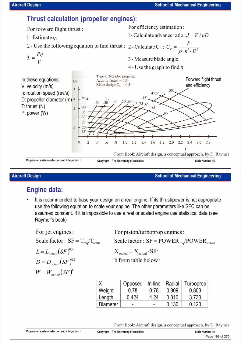
Aircraft Design School of Mechanical Engineering
Thrust calculation (propeller engines):
PηT =
: thrustfind oequation t following the Use-2
. Estimate -1
:ustflight thr forwardFor
η
angle. blade Measure -3
:C Calculate -2
/ :ratio advance Calculate -1
:estimation efficiencyFor
53P ρ Dn
PC
nDVJ
P ⋅⋅=
=
VT =
. find graph to the Use-4
angle. blade Measure -3
η
Forward flight thrust and efficiency
In these equations:V: velocity (m/s)n: rotation speed (rev/s)D: propeller diameter (m)T: thrust (N)P: power (W)
Propulsion system selection and integration I Copyright - The University of Adelaide Slide Number 15
From Book: Aircraft design, a conceptual approach, by D. Raymer
P: power (W)
Aircraft Design School of Mechanical Engineering
Engine data:
• It is recommended to base your design on a real engine. If its thrust/power is not appropriate use the following equation to scale your engine. The other parameters like SFC can be assumed constant. If it is impossible to use a real or scaled engine use statistical data (see Raymer’s book)
:enginesjet For
( )( )( ) 1.1
5.0
4.0
actualreq/TTSF :factor Scale
:enginesjet For
SFWW
SFDD
SFLL
actual
actual
actual
=
=
=
=
:below tablefrom b
SFXX
/POWERPOWERSF :factor Scale
:engines boproppiston/turFor
b
actualscaled
actualreq
⋅=
=
X Opposed In-line Radial Turboprop
Propulsion system selection and integration I Copyright - The University of Adelaide Slide Number 16
X Opposed In-line Radial Turboprop Weight 0.78 0.78 0.809 0.803 Length 0.424 4.24 0.310 3.730 Diameter - - 0.130 0.120
From Book: Aircraft design, a conceptual approach, by D. Raymer
Page 199 of 270

Aircraft Design School of Mechanical Engineering
Integration of the propulsion system• Make a decision about the number of the engines to be employed. (more engine more
reliable aircraft and less propulsion failure probability, however it increases the cost and weight of the propulsion system and operational cost of the aircraft)
• Decide on the place where the engines can be mounted (the wing, the fuselage, the empennage or a combination of those). Consider the followings:– Effect of power changes on stability and control– Effect of power changes on stability and control– Drag of proposed installation– Weight and balance– Inlet requirement– Accessibility and maintainability– Ground/surface clearance– Internal and external noise– Stealthiness– Gun installation
Propulsion system
positioning depends
on aircraft overall
Propulsion system selection and integration I Copyright - The University of Adelaide Slide Number 17
– Gun installation– Engine thrust reversing requirements– Engine accessories– Engine installation and isolation requirements– Engine cooling requirements
• Prepare a 3-view/3-D drawing• Document your decision and your arguments supporting your decision
on aircraft overall
configuration
Aircraft Design School of Mechanical Engineering
Intentionally left blank for your notes
………………………………………………………………………………………………
………………………………………………………………………………………………
………………………………………………………………………………………………
………………………………………………………………………………………………………………………………………………………………………………………………
………………………………………………………………………………………………
………………………………………………………………………………………………
………………………………………………………………………………………………
………………………………………………………………………………………………
………………………………………………………………………………………………
………………………………………………………………………………………………
………………………………………………………………………………………………
………………………………………………………………………………………………
………………………………………………………………………………………………
Propulsion system selection and integration I Copyright - The University of Adelaide Slide Number 18
………………………………………………………………………………………………
………………………………………………………………………………………………
………………………………………………………………………………………………
………………………………………………………………………………………………
………………………………………………………………………………………………
………………………………………………………………………………………….
Page 200 of 270

Aircraft Design School of Mechanical Engineering
Integration of jet engines:• In passenger and transport aircraft: engines are located above/under the wing, on the aft-
fuselage or combination of both. – The under-wing configuration is very common as it eases the maintenance, reduces the noise in the cabin and the engine weight reduces the total wing loading, hence reduces the wing weight. However presence of pods and pylons disturbs the airflow on the wing, reduces the lift and increases the drag and also increases the possibility of foreign object ingestion by suction into the inlets.ingestion by suction into the inlets.
– The over-wing configuration reduces noise on the ground, reduces landing gear height and increases wing lift coefficient through Coanda effect, however it increases noise in the cabin, reduces the lifetime of the upper surface panels of the wing and also generates very dangerous rolling moment in takeoff and landing due to engine failures
– The aft-fuselage engine eliminates the wing-interference effects of wing-mounted engines and allows a short landing gear. However it increases the noise in the cabin and CG range and makes the aircraft tail-heavy especially in landing configuration. Moreover it reduces the horizontal and vertical tail arm which necessitates a larger vertical and horizontal tail. In the case of buried-engine in the aft-fuselage, it requires very complicated and heavy air inlet.
Propulsion system selection and integration I Copyright - The University of Adelaide Slide Number 19
and heavy air inlet.– The wing-tip mounted engine has an obvious engine-out controllability problem. This configuration is rarely used.
From Book: Aircraft design, a conceptual approach, by D. Raymer
Aircraft Design School of Mechanical Engineering
Integration of jet engines:• In fighters: engines are located in the wing and wing root, in/on the aft-fuselage or
combination of all. The inlet position and geometry have great effect on engine performance in different flight configuration.
– The nose inlet was used in most early fighters. It offers the inlet a completely clean airflow, however it needs a very long and heavy internal duct.and heavy internal duct.
– The chin inlet has the most advantages of the nose inlet but a shorter duct length, however the location of the nose landing gear is a problem
– The side-mounted inlets are used in the aircraft with two engines. This configuration offers the inlet a clean airflow, however it can have some problems in manoeuvres due to the vortex ingestion.
Propulsion system selection and integration I Copyright - The University of Adelaide Slide Number 20
From Book: Aircraft design, a conceptual
approach, by D. Raymer
ingestion.– Armpit inlet is the inlet which is placed at the intersection of the wing and fuselage. It offers a very short inlet duct, however the thick boundary layer in the wing-fuselage corner can be ingested into the intakes and also increases the structural weight of the wing
Page 201 of 270
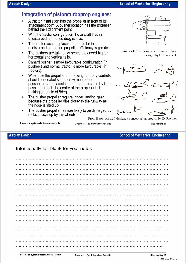
Aircraft Design School of Mechanical Engineering
Integration of piston/turboprop engines:• A tractor installation has the propeller in front of its
attachment point. A pusher location has the propeller behind the attachment point.
• With the tractor configuration the aircraft flies in undisturbed air, hence drag is less.
• The tractor location places the propeller in • The tractor location places the propeller in undisturbed air, hence propeller efficiency is greater.
• The pushers are tail-heavy hence they need bigger horizontal and vertical tails.
• Canard pusher is more favourable configuration (in pushers) and normal tractor is more favourable (in tractors).
• When use the propeller on the wing, primary controls should be located so, no crew members or passengers are placed in the area generated by lines passing through the centre of the propeller hub
From Book: Synthesis of subsonic airplane
design, by E. Torenbeek
Propulsion system selection and integration I Copyright - The University of Adelaide Slide Number 21
passing through the centre of the propeller hub making an angle of 5deg.
• The pusher propeller require longer landing gear because the propeller dips closer to the runway as the nose is lifted up.
• The pusher propeller is more likely to be damaged by rocks thrown up by the wheels.
From Book: Aircraft design, a conceptual approach, by D. Raymer
Aircraft Design School of Mechanical Engineering
Intentionally left blank for your notes
………………………………………………………………………………………………
………………………………………………………………………………………………
………………………………………………………………………………………………
………………………………………………………………………………………………………………………………………………………………………………………………
………………………………………………………………………………………………
………………………………………………………………………………………………
………………………………………………………………………………………………
………………………………………………………………………………………………
………………………………………………………………………………………………
………………………………………………………………………………………………
………………………………………………………………………………………………
………………………………………………………………………………………………
………………………………………………………………………………………………
Propulsion system selection and integration I Copyright - The University of Adelaide Slide Number 22
………………………………………………………………………………………………
………………………………………………………………………………………………
………………………………………………………………………………………………
………………………………………………………………………………………………
………………………………………………………………………………………………
………………………………………………………………………………………….
Page 202 of 270
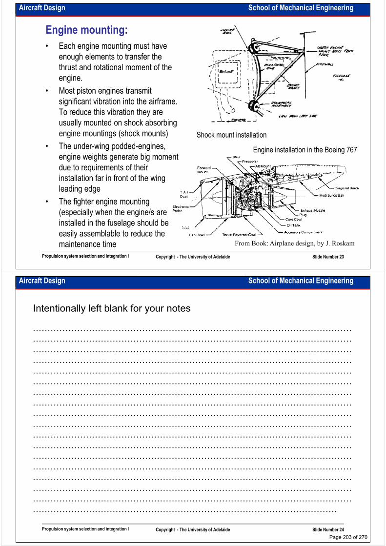
Aircraft Design School of Mechanical Engineering
Engine mounting:
• Each engine mounting must have enough elements to transfer the thrust and rotational moment of the engine.
• Most piston engines transmit • Most piston engines transmit significant vibration into the airframe. To reduce this vibration they are usually mounted on shock absorbing engine mountings (shock mounts)
• The under-wing podded-engines, engine weights generate big moment due to requirements of their installation far in front of the wing
Engine installation in the Boeing 767
Shock mount installation
Propulsion system selection and integration I Copyright - The University of Adelaide Slide Number 23
installation far in front of the wing leading edge
• The fighter engine mounting (especially when the engine/s are installed in the fuselage should be easily assemblable to reduce the maintenance time From Book: Airplane design, by J. Roskam
Aircraft Design School of Mechanical Engineering
Intentionally left blank for your notes
………………………………………………………………………………………………
………………………………………………………………………………………………
………………………………………………………………………………………………
………………………………………………………………………………………………………………………………………………………………………………………………
………………………………………………………………………………………………
………………………………………………………………………………………………
………………………………………………………………………………………………
………………………………………………………………………………………………
………………………………………………………………………………………………
………………………………………………………………………………………………
………………………………………………………………………………………………
………………………………………………………………………………………………
………………………………………………………………………………………………
Propulsion system selection and integration I Copyright - The University of Adelaide Slide Number 24
………………………………………………………………………………………………
………………………………………………………………………………………………
………………………………………………………………………………………………
………………………………………………………………………………………………
………………………………………………………………………………………………
………………………………………………………………………………………….
Page 203 of 270
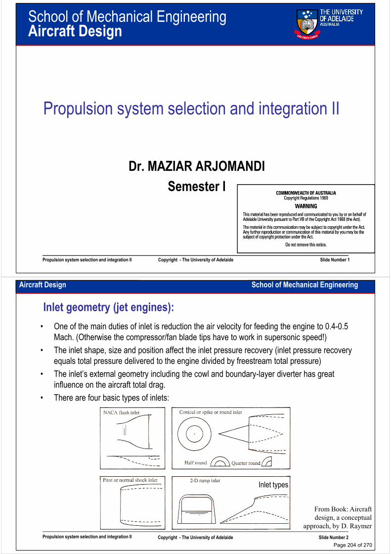
School of Mechanical EngineeringAircraft Design
Propulsion system selection and integration II
Dr. MAZIAR ARJOMANDI
Semester I
Propulsion system selection and integration II Copyright - The University of Adelaide Slide Number 1
Semester I
Aircraft Design School of Mechanical Engineering
Inlet geometry (jet engines):
• One of the main duties of inlet is reduction the air velocity for feeding the engine to 0.4-0.5
Mach. (Otherwise the compressor/fan blade tips have to work in supersonic speed!)
• The inlet shape, size and position affect the inlet pressure recovery (inlet pressure recovery
equals total pressure delivered to the engine divided by freestream total pressure)
• The inlet’s external geometry including the cowl and boundary-layer diverter has great • The inlet’s external geometry including the cowl and boundary-layer diverter has great
influence on the aircraft total drag.
• There are four basic types of inlets:
Propulsion system selection and integration II Copyright - The University of Adelaide Slide Number 2
From Book: Aircraft
design, a conceptual
approach, by D. Raymer
Inlet types
Page 204 of 270

Aircraft Design School of Mechanical Engineering
Inlet geometry (jet engines):
• NACA flash inlet is rarely used today for aircraft propulsion system due to its poor pressure recovery. NACA inlet is regularly used for cooling air and auxiliary power units, where pressure recovery is less units, where pressure recovery is less important.
• The pitot inlet is simply a forward-facing hole and works very well at low subsonic speeds. When it is used for subsonic flight it is called “normal shock inlet” as it generates normal shock. The cowl lip radius has a major effect upon engine performance and aircraft drag.
• The conical (spike) and ram-air (D-shape) inlet are for supersonic speeds. They exploit
Propulsion system selection and integration II Copyright - The University of Adelaide Slide Number 3
inlet are for supersonic speeds. They exploit shock patterns created by supersonic flow over a cone or wedge. The spike inlet has better pressure recovery but has more drag, is heavier and involves much more complicated mechanism to produce variable geometry.
From Book: Aircraft design, a conceptual
approach, by D. Raymer
Supersonic inlets
Aircraft Design School of Mechanical Engineering
Intentionally left blank for your notes
………………………………………………………………………………………………
………………………………………………………………………………………………
………………………………………………………………………………………………
………………………………………………………………………………………………………………………………………………………………………………………………
………………………………………………………………………………………………
………………………………………………………………………………………………
………………………………………………………………………………………………
………………………………………………………………………………………………
………………………………………………………………………………………………
………………………………………………………………………………………………
………………………………………………………………………………………………
………………………………………………………………………………………………
………………………………………………………………………………………………
Propulsion system selection and integration II Copyright - The University of Adelaide Slide Number 4
………………………………………………………………………………………………
………………………………………………………………………………………………
………………………………………………………………………………………………
………………………………………………………………………………………………
………………………………………………………………………………………………
………………………………………………………………………………………….
Page 205 of 270
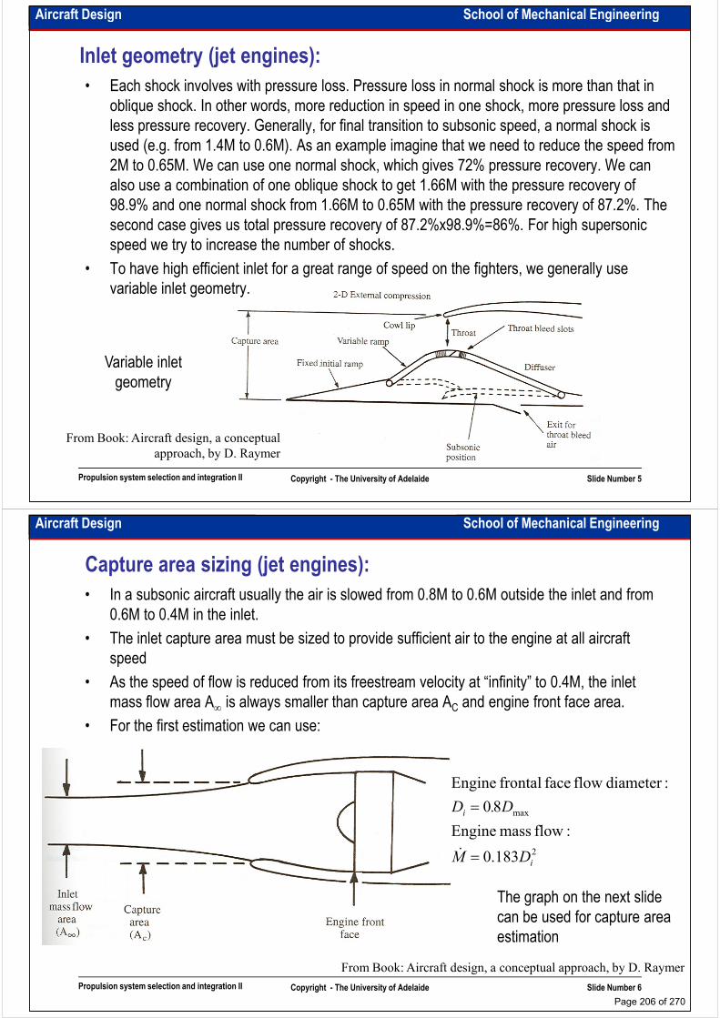
Aircraft Design School of Mechanical Engineering
Inlet geometry (jet engines):
• Each shock involves with pressure loss. Pressure loss in normal shock is more than that in
oblique shock. In other words, more reduction in speed in one shock, more pressure loss and
less pressure recovery. Generally, for final transition to subsonic speed, a normal shock is
used (e.g. from 1.4M to 0.6M). As an example imagine that we need to reduce the speed from
2M to 0.65M. We can use one normal shock, which gives 72% pressure recovery. We can 2M to 0.65M. We can use one normal shock, which gives 72% pressure recovery. We can
also use a combination of one oblique shock to get 1.66M with the pressure recovery of
98.9% and one normal shock from 1.66M to 0.65M with the pressure recovery of 87.2%. The
second case gives us total pressure recovery of 87.2%x98.9%=86%. For high supersonic
speed we try to increase the number of shocks.
• To have high efficient inlet for a great range of speed on the fighters, we generally use
variable inlet geometry.
Propulsion system selection and integration II Copyright - The University of Adelaide Slide Number 5
From Book: Aircraft design, a conceptual
approach, by D. Raymer
Variable inlet
geometry
Aircraft Design School of Mechanical Engineering
Capture area sizing (jet engines):
• In a subsonic aircraft usually the air is slowed from 0.8M to 0.6M outside the inlet and from
0.6M to 0.4M in the inlet.
• The inlet capture area must be sized to provide sufficient air to the engine at all aircraft
speed
• As the speed of flow is reduced from its freestream velocity at “infinity” to 0.4M, the inlet • As the speed of flow is reduced from its freestream velocity at “infinity” to 0.4M, the inlet
mass flow area A∞ is always smaller than capture area AC and engine front face area.
• For the first estimation we can use:
max
:flow mass Engine
80
:diameter flow face frontal Engine
i D.D
=
ɺ
Propulsion system selection and integration II Copyright - The University of Adelaide Slide Number 6
From Book: Aircraft design, a conceptual approach, by D. Raymer
2183.0 iDM =ɺ
The graph on the next slide
can be used for capture area
estimation
Page 206 of 270
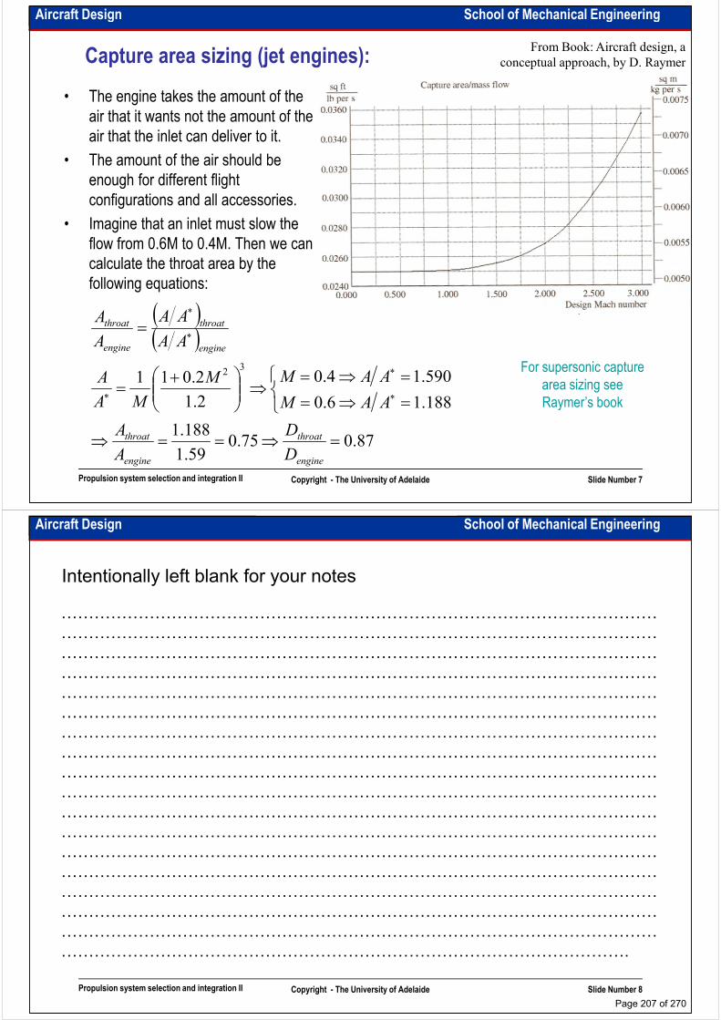
Aircraft Design School of Mechanical Engineering
Capture area sizing (jet engines):
• The engine takes the amount of the
air that it wants not the amount of the
air that the inlet can deliver to it.
• The amount of the air should be
enough for different flight
From Book: Aircraft design, a
conceptual approach, by D. Raymer
enough for different flight
configurations and all accessories.
• Imagine that an inlet must slow the
flow from 0.6M to 0.4M. Then we can
calculate the throat area by the
following equations:
( )( )=
∗
∗throatthroat
AA
AA
A
A
Propulsion system selection and integration II Copyright - The University of Adelaide Slide Number 7
( )
87.075.059.1
188.1
188.16.0
590.14.0
2.1
2.0113
2
=⇒==⇒
=⇒=
=⇒=⇒
+=
∗
∗
∗
∗
engine
throat
engine
throat
engineengine
D
D
A
A
AAM
AAMM
MA
A
AAA
For supersonic capture
area sizing see
Raymer’s book
Aircraft Design School of Mechanical Engineering
Intentionally left blank for your notes
………………………………………………………………………………………………
………………………………………………………………………………………………
………………………………………………………………………………………………
………………………………………………………………………………………………………………………………………………………………………………………………
………………………………………………………………………………………………
………………………………………………………………………………………………
………………………………………………………………………………………………
………………………………………………………………………………………………
………………………………………………………………………………………………
………………………………………………………………………………………………
………………………………………………………………………………………………
………………………………………………………………………………………………
………………………………………………………………………………………………
Propulsion system selection and integration II Copyright - The University of Adelaide Slide Number 8
………………………………………………………………………………………………
………………………………………………………………………………………………
………………………………………………………………………………………………
………………………………………………………………………………………………
………………………………………………………………………………………………
………………………………………………………………………………………….
Page 207 of 270
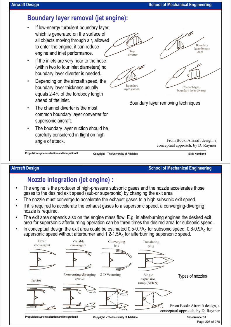
Aircraft Design School of Mechanical Engineering
Boundary layer removal (jet engine):
• If low-energy turbulent boundary layer,
which is generated on the surface of
all objects moving through air, allowed
to enter the engine, it can reduce
engine and inlet performance.engine and inlet performance.
• If the inlets are very near to the nose
(within two to four inlet diameters) no
boundary layer diverter is needed.
• Depending on the aircraft speed, the
boundary layer thickness usually
equals 2-4% of the forebody length
ahead of the inlet.
• The channel diverter is the most Boundary layer removing techniques
Propulsion system selection and integration II Copyright - The University of Adelaide Slide Number 9
• The channel diverter is the most
common boundary layer converter for
supersonic aircraft.
• The boundary layer suction should be
carefully considered in flight on high
angle of attack. From Book: Aircraft design, a
conceptual approach, by D. Raymer
Aircraft Design School of Mechanical Engineering
Nozzle integration (jet engine) :• The engine is the producer of high-pressure subsonic gases and the nozzle accelerates those
gases to the desired exit speed (sub-or supersonic) by changing the exit area
• The nozzle must converge to accelerate the exhaust gases to a high subsonic exit speed.
• If it is required to accelerate the exhaust gases to a supersonic speed, a converging-diverging nozzle is required.
• The exit area depends also on the engine mass flow. E.g. in afterburning engines the desired exit • The exit area depends also on the engine mass flow. E.g. in afterburning engines the desired exit area for supersonic afterburning operation can be three times the desired area for subsonic speed.
• In conceptual design the exit area could be estimated 0.5-0.7AC for subsonic speed, 0.6-0.9AC for supersonic speed without afterburner and 1.2-1.5AC for afterburning supersonic speed.
Propulsion system selection and integration II Copyright - The University of Adelaide Slide Number 10
Types of nozzles
From Book: Aircraft design, a
conceptual approach, by D. Raymer
Page 208 of 270
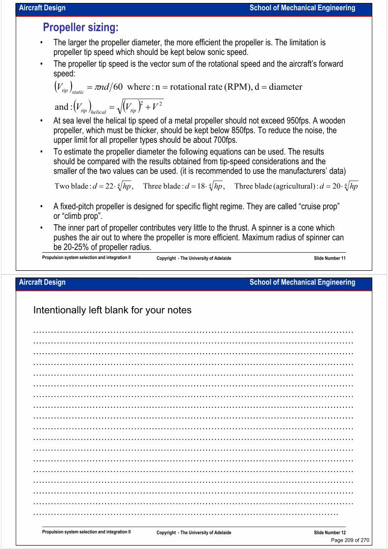
Aircraft Design School of Mechanical Engineering
Propeller sizing:
• The larger the propeller diameter, the more efficient the propeller is. The limitation is propeller tip speed which should be kept below sonic speed.
• The propeller tip speed is the vector sum of the rotational speed and the aircraft’s forward speed:
( ) diameterd (RPM), rate rotationaln : where60ndVstatictip === π
• At sea level the helical tip speed of a metal propeller should not exceed 950fps. A wooden propeller, which must be thicker, should be kept below 850fps. To reduce the noise, the upper limit for all propeller types should be about 700fps.
• To estimate the propeller diameter the following equations can be used. The results should be compared with the results obtained from tip-speed considerations and the smaller of the two values can be used. (it is recommended to use the manufacturers’ data)
( )( ) ( ) 22 :and VVV tiphelicaltip
statictip
+=
20 :ral)(agricultu blade Three ,18 :blade Three ,22 :blade Two hpdhpdhpd ⋅=⋅=⋅=
Propulsion system selection and integration II Copyright - The University of Adelaide Slide Number 11
• A fixed-pitch propeller is designed for specific flight regime. They are called “cruise prop” or “climb prop”.
• The inner part of propeller contributes very little to the thrust. A spinner is a cone which pushes the air out to where the propeller is more efficient. Maximum radius of spinner can be 20-25% of propeller radius.
444 20 :ral)(agricultu blade Three ,18 :blade Three ,22 :blade Two hpdhpdhpd ⋅=⋅=⋅=
Aircraft Design School of Mechanical Engineering
Intentionally left blank for your notes
………………………………………………………………………………………………
………………………………………………………………………………………………
………………………………………………………………………………………………
………………………………………………………………………………………………………………………………………………………………………………………………
………………………………………………………………………………………………
………………………………………………………………………………………………
………………………………………………………………………………………………
………………………………………………………………………………………………
………………………………………………………………………………………………
………………………………………………………………………………………………
………………………………………………………………………………………………
………………………………………………………………………………………………
………………………………………………………………………………………………
Propulsion system selection and integration II Copyright - The University of Adelaide Slide Number 12
………………………………………………………………………………………………
………………………………………………………………………………………………
………………………………………………………………………………………………
………………………………………………………………………………………………
………………………………………………………………………………………………
………………………………………………………………………………………….
Page 209 of 270

Aircraft Design School of Mechanical Engineering
Propeller efficiency:
• Installed propeller efficiency depends upon the following factors:
– Activity factor AF
– Airfoils of the blades
– Pitch distribution
– Propeller blockage
– Number of blades
– Tip Mach number
– Single or counter rotation
– Disk loading and power loading– Pitch distribution – Disk loading and power loading
Propulsion system selection and integration II Copyright - The University of Adelaide Slide Number 13
From Book: Airplane design, by J. Roskam
Installed propeller efficiencyEffect of number of blades and of disk
loading on propeller efficiency
Aircraft Design School of Mechanical Engineering
Piston engine installation:• In piston engines cooling is a major concern
• Up to 10% of the engine’s power can be wasted by the drag associated with taking in cooling air, passing it over the engine and exiting it
• The cooling air intake should be about 30-50% of the engine frontal area. The cooling air exit area should be about 30% larger
• To control the cooling air flow cowl-flaps are used.• To control the cooling air flow cowl-flaps are used.
• The baffles are flat sheets of metal which direct the airflow to the engine compartments
• The firewall is typically a 0.015-in steel sheet attached to the first structural bulkhead of the fuselage or nacelle. It prevents a fire in the engine compartment to be spread into the rest of the aircraft.
• In canard configuration the cooling air intake frontal area should be larger as boundary layer at the end of the fuselage is very thick
Piston engine installation
Propulsion system selection and integration II Copyright - The University of Adelaide Slide Number 14
From Book: Aircraft design, a conceptual approach, by D. Raymer
Page 210 of 270

Aircraft Design School of Mechanical Engineering
Fuel system: Fuel system
installation
(PIPER PA-38-112)
• Fuel system includes the fuel tanks, fuel lines, fuel pumps, vents, fuel-management controls, fuel quantity measurement and indicating system and fuel flow quantity measurement and indicating system.
• There are three types of fuel tank:• There are three types of fuel tank:
– Discrete: metallic or composite, fabricated separately and mounted by bolts or straps.
– Bladder: made by stuffing a shaped rubber bag into a cavity in the structure. They are thick and heavy but self-sealing.
– Integrated: is a part of aircraft structure. It is a cavity within the airframe structure that are sealed to
Propulsion system selection and integration II Copyright - The University of Adelaide Slide Number 15
From Book: Airplane design, by J. Roskam
airframe structure that are sealed to form a fuel tank.
• The required volume of the fuel is calculated during mission sizing. This can be used to calculate required volume of tanks. The available volume inside the wing or fuselage can be estimated using the sketches.
Aircraft Design School of Mechanical Engineering
Intentionally left blank for your notes
………………………………………………………………………………………………
………………………………………………………………………………………………
………………………………………………………………………………………………
………………………………………………………………………………………………………………………………………………………………………………………………
………………………………………………………………………………………………
………………………………………………………………………………………………
………………………………………………………………………………………………
………………………………………………………………………………………………
………………………………………………………………………………………………
………………………………………………………………………………………………
………………………………………………………………………………………………
………………………………………………………………………………………………
………………………………………………………………………………………………
Propulsion system selection and integration II Copyright - The University of Adelaide Slide Number 16
………………………………………………………………………………………………
………………………………………………………………………………………………
………………………………………………………………………………………………
………………………………………………………………………………………………
………………………………………………………………………………………………
………………………………………………………………………………………….
Page 211 of 270
School of Mechanical EngineeringAircraft Design
Wing design considerations I
Dr. MAZIAR ARJOMANDI
Semester I
Wing design considerations I Copyright - The University of Adelaide Slide Number 1
Semester I
Aircraft Design School of Mechanical Engineering
Vertical position of wing:• If “everything else” in the aircraft with different wing positioning (low wing - LW, mid wing -
MW, high wing - HW) is the same the following comparison can be done:
– Lateral stability: HW has the highest lateral stability and LW has the least. (As the result of sideslip, more lift will be generated on the lower wing. The lower the centre of gravity is the greater will be the moment arm.)
– Interference drag: LW has the highest interference drag and MW has the least. (In – Interference drag: LW has the highest interference drag and MW has the least. (In LW flow speed on upper surface of wing in more than on lower surface in HW. In MW because of less height of fuselage above or under the wing, best fillet could be designed.)
– Visibility from cabin: HW has the best visibility from cabin and LW has the worst. (If upward visibility is needed then the order will be changed. In some small aircraft, the wing panels above the cabin are transparent. This is one reason that MW configuration is more preferable for fighters!)
– Landing gear weight: LW has the lightest landing gear and HW has the heaviest. (If in
Wing design considerations I Copyright - The University of Adelaide Slide Number 2
– Landing gear weight: LW has the lightest landing gear and HW has the heaviest. (If in HW landing gears are connected to wing, they need very long strut and if to fuselage they need a big bay.)
– Crashworthiness: LW is more survivable in crashes and HW is less. (In HW the fuselage, where the payload is, should bear all the impact loads generated by the wing in a crash. Moreover in the case of emergency landing on the water, part of the fuselage which is under the wing will be immersed in the water.
Page 212 of 270
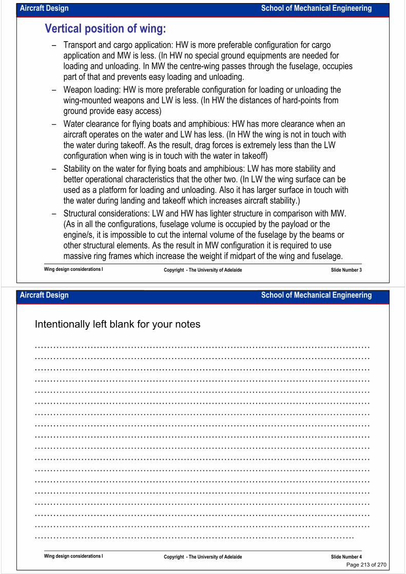
Aircraft Design School of Mechanical Engineering
Vertical position of wing:
– Transport and cargo application: HW is more preferable configuration for cargo application and MW is less. (In HW no special ground equipments are needed for loading and unloading. In MW the centre-wing passes through the fuselage, occupies part of that and prevents easy loading and unloading.
– Weapon loading: HW is more preferable configuration for loading or unloading the wing-mounted weapons and LW is less. (In HW the distances of hard-points from wing-mounted weapons and LW is less. (In HW the distances of hard-points from ground provide easy access)
– Water clearance for flying boats and amphibious: HW has more clearance when an aircraft operates on the water and LW has less. (In HW the wing is not in touch with the water during takeoff. As the result, drag forces is extremely less than the LW configuration when wing is in touch with the water in takeoff)
– Stability on the water for flying boats and amphibious: LW has more stability and better operational characteristics that the other two. (In LW the wing surface can be used as a platform for loading and unloading. Also it has larger surface in touch with
Wing design considerations I Copyright - The University of Adelaide Slide Number 3
used as a platform for loading and unloading. Also it has larger surface in touch with the water during landing and takeoff which increases aircraft stability.)
– Structural considerations: LW and HW has lighter structure in comparison with MW. (As in all the configurations, fuselage volume is occupied by the payload or the engine/s, it is impossible to cut the internal volume of the fuselage by the beams or other structural elements. As the result in MW configuration it is required to use massive ring frames which increase the weight if midpart of the wing and fuselage.
Aircraft Design School of Mechanical Engineering
Intentionally left blank for your notes
………………………………………………………………………………………………
………………………………………………………………………………………………
………………………………………………………………………………………………
………………………………………………………………………………………………………………………………………………………………………………………………
………………………………………………………………………………………………
………………………………………………………………………………………………
………………………………………………………………………………………………
………………………………………………………………………………………………
………………………………………………………………………………………………
………………………………………………………………………………………………
………………………………………………………………………………………………
………………………………………………………………………………………………
………………………………………………………………………………………………
Wing design considerations I Copyright - The University of Adelaide Slide Number 4
………………………………………………………………………………………………
………………………………………………………………………………………………
………………………………………………………………………………………………
………………………………………………………………………………………………
………………………………………………………………………………………………
………………………………………………………………………………………….
Page 213 of 270

Aircraft Design School of Mechanical Engineering
Wing loading:• As the result of sizing there is not a specific number for wing loading but the wing loading
could be varied in a quite large range, depending upon performance parameters. The question is high wing loading is better or low wing loading.
– Takeoff and landing field length: As it was discussed it is directly related to the amount of wing loading. The lower wing loading is the shorter is the field length. The wing area can be kept small by using flaps.wing area can be kept small by using flaps.
– Cruise performance: The higher wing loading is the closer the cruise lift coefficient to that at (L/D)max. (this is the reason why transport jets tend to have high wing loading and use very effective flaps)
– High altitude flight: For flight on high altitude a large wing area (low wing loading) is required. (this is the reason why U-2 has very large wing area and moderate speed)
– Ride trough turbulence: The lower the wing loading is, the higher is the response of the aircraft to the changing of angle of attack which translates into poor ride quality. (This is the reason why flight on big jet transports with high wing loading is more comfortable than flight on small jet transport with low wing loading. The flight of GA
Wing design considerations I Copyright - The University of Adelaide Slide Number 5
comfortable than flight on small jet transport with low wing loading. The flight of GA aircraft is usually very uncomfortable and bumpy.)
– Weight: The wing weight is a direct function of its area. The larger wing is, the lower is the wing loading and the higher is the weight of the wing.
– Manufacturing cost and complexity: The high wing loading wing is manufactured by using more expensive material and more complex manufacturing operations. Hence high wing loading wing is more expensive and more complicated in production.
Aircraft Design School of Mechanical Engineering
Wing sweep:• Three main configuration will be considered: forward sweep - FS, aft sweep - AS and no
sweep - NS. Variable sweep and oblique wing are not discussed as they are the combination on these three main configurations.
– Compressibility drag: FS and AS have similar favourable effect on compressibility drag. It means that FS and AS yield similar reduction in compressibility drag.
– Weight: NS configuration is the lightest. FS is associated with structural divergence – Weight: NS configuration is the lightest. FS is associated with structural divergence phenomenon. To prevent divergence it must be designed stiffer hence it is heavier than AS. By tailoring the ratio of bending to torsion stiffness (using the composite materials) it is possible to control structural divergence in FS configuration.
Wing design considerations I Copyright - The University of Adelaide Slide Number 6
From Book: Airplane design, by J. Roskam
Effect of sweep on wing
weighthttp://www.centennialofflight.govEffect of sweep on
compressibility drag
Page 214 of 270

Aircraft Design School of Mechanical Engineering
Wing sweep:– Stall behaviour: In AS configuration, wingtips stall first which leads to reduction of the ailerons effectiveness and loss of lateral control.
– Balance: AS or FS can be used for increasing or decreasing aircraft longitudinal stability. If the sweep angle is slightly increased/decreases, the aerodynamic centre (AC) moves faster than centre of gravity (CG) and increases/decreases the aircraft static margin (SM). Also it changes the longitudinal moment arm which has a beneficial effect margin (SM). Also it changes the longitudinal moment arm which has a beneficial effect on the inherent longitudinal damping characteristics of the aircraft.
– Pitch altitude and ride: Increasing the sweep angle reduces the lift-curve slope. As the result of that the aircraft with high sweep angle tends to have more pitch attitude at low speed therefore they have less runway visibility. On the other hand, high sweep improves ride quality.
Wing design considerations I Copyright - The University of Adelaide Slide Number 7
From Book: Airplane design, by J. Roskam Effect of sweep on lift curve slope
Effect of sweep on stall behaviour
Aircraft Design School of Mechanical Engineering
Intentionally left blank for your notes
………………………………………………………………………………………………
………………………………………………………………………………………………
………………………………………………………………………………………………
………………………………………………………………………………………………………………………………………………………………………………………………
………………………………………………………………………………………………
………………………………………………………………………………………………
………………………………………………………………………………………………
………………………………………………………………………………………………
………………………………………………………………………………………………
………………………………………………………………………………………………
………………………………………………………………………………………………
………………………………………………………………………………………………
………………………………………………………………………………………………
Wing design considerations I Copyright - The University of Adelaide Slide Number 8
………………………………………………………………………………………………
………………………………………………………………………………………………
………………………………………………………………………………………………
………………………………………………………………………………………………
………………………………………………………………………………………………
………………………………………………………………………………………….
Page 215 of 270
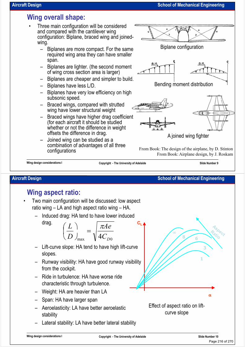
Aircraft Design School of Mechanical Engineering
Wing overall shape:• Three main configuration will be considered
and compared with the cantilever wing configuration: Biplane, braced wing and joined-wing.
– Biplanes are more compact. For the same required wing area they can have smaller span.
Biplane configuration
span.
– Biplanes are lighter. (the second moment of wing cross section area is larger)
– Biplanes are cheaper and simpler to build.
– Biplanes have less L/D.
– Biplanes have very low efficiency on high subsonic speed.
– Braced wings, compared with strutted wing have lower structural weight
– Braced wings have higher drag coefficient
Bending moment distribution
Wing design considerations I Copyright - The University of Adelaide Slide Number 9
From Book: Airplane design, by J. Roskam
– Braced wings have higher drag coefficient (for each aircraft it should be studied whether or not the difference in weight offsets the difference in drag.
– Joined wing can be studied as a combination of advantages of all three configurations From Book: The design of the airplane, by D. Stinton
A joined wing fighter
Aircraft Design School of Mechanical Engineering
Wing aspect ratio:• Two main configuration will be discussed: low aspect
ratio wing – LA and high aspect ratio wing – HA.
– Induced drag: HA tend to have lower induced
drag.AeL π
=
CL
∞∞∞∞
– Lift-curve slope: HA tend to have high lift-curve
slopes.
– Runway visibility: HA have good runway visibility
from the cockpit.
– Ride in turbulence: HA have worse ride
characteristic through turbulence.
0max 4DCD
=
1
3
68
∞∞∞∞
Wing design considerations I Copyright - The University of Adelaide Slide Number 10
– Weight: HA are heavier than LA
– Span: HA have larger span
– Aeroelasticity: LA have better aeroelastic
stability
– Lateral stability: LA have better lateral stability
αααα
Effect of aspect ratio on lift-
curve slope
Page 216 of 270
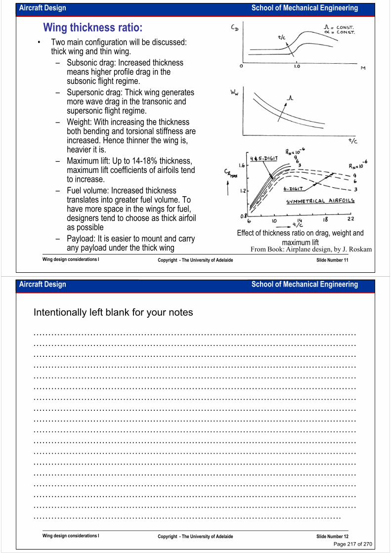
Aircraft Design School of Mechanical Engineering
Wing thickness ratio:• Two main configuration will be discussed:
thick wing and thin wing.
– Subsonic drag: Increased thickness means higher profile drag in the subsonic flight regime.
– Supersonic drag: Thick wing generates – Supersonic drag: Thick wing generates more wave drag in the transonic and supersonic flight regime.
– Weight: With increasing the thickness both bending and torsional stiffness are increased. Hence thinner the wing is, heavier it is.
– Maximum lift: Up to 14-18% thickness, maximum lift coefficients of airfoils tend to increase.
Wing design considerations I Copyright - The University of Adelaide Slide Number 11
to increase.
– Fuel volume: Increased thickness translates into greater fuel volume. To have more space in the wings for fuel, designers tend to choose as thick airfoil as possible
– Payload: It is easier to mount and carry any payload under the thick wing
Effect of thickness ratio on drag, weight and
maximum liftFrom Book: Airplane design, by J. Roskam
Aircraft Design School of Mechanical Engineering
Intentionally left blank for your notes
………………………………………………………………………………………………
………………………………………………………………………………………………
………………………………………………………………………………………………
………………………………………………………………………………………………………………………………………………………………………………………………
………………………………………………………………………………………………
………………………………………………………………………………………………
………………………………………………………………………………………………
………………………………………………………………………………………………
………………………………………………………………………………………………
………………………………………………………………………………………………
………………………………………………………………………………………………
………………………………………………………………………………………………
………………………………………………………………………………………………
Wing design considerations I Copyright - The University of Adelaide Slide Number 12
………………………………………………………………………………………………
………………………………………………………………………………………………
………………………………………………………………………………………………
………………………………………………………………………………………………
………………………………………………………………………………………………
………………………………………………………………………………………….
Page 217 of 270
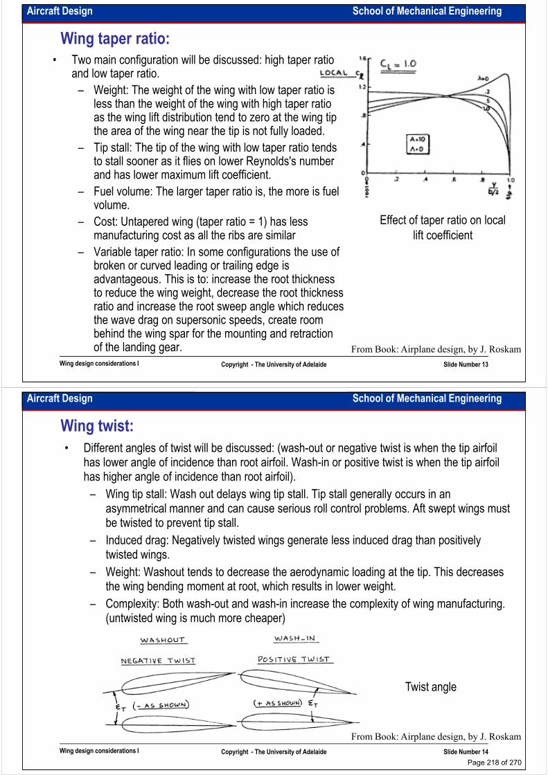
Aircraft Design School of Mechanical Engineering
Wing taper ratio:
• Two main configuration will be discussed: high taper ratio and low taper ratio.
– Weight: The weight of the wing with low taper ratio is less than the weight of the wing with high taper ratio as the wing lift distribution tend to zero at the wing tip the area of the wing near the tip is not fully loaded.the area of the wing near the tip is not fully loaded.
– Tip stall: The tip of the wing with low taper ratio tends to stall sooner as it flies on lower Reynolds's number and has lower maximum lift coefficient.
– Fuel volume: The larger taper ratio is, the more is fuel volume.
– Cost: Untapered wing (taper ratio = 1) has less manufacturing cost as all the ribs are similar
– Variable taper ratio: In some configurations the use of
Effect of taper ratio on local
lift coefficient
Wing design considerations I Copyright - The University of Adelaide Slide Number 13
– Variable taper ratio: In some configurations the use of broken or curved leading or trailing edge is advantageous. This is to: increase the root thickness to reduce the wing weight, decrease the root thickness ratio and increase the root sweep angle which reduces the wave drag on supersonic speeds, create room behind the wing spar for the mounting and retraction of the landing gear. From Book: Airplane design, by J. Roskam
Aircraft Design School of Mechanical Engineering
Wing twist:
• Different angles of twist will be discussed: (wash-out or negative twist is when the tip airfoil has lower angle of incidence than root airfoil. Wash-in or positive twist is when the tip airfoil has higher angle of incidence than root airfoil).
– Wing tip stall: Wash out delays wing tip stall. Tip stall generally occurs in an asymmetrical manner and can cause serious roll control problems. Aft swept wings must be twisted to prevent tip stall.be twisted to prevent tip stall.
– Induced drag: Negatively twisted wings generate less induced drag than positively twisted wings.
– Weight: Washout tends to decrease the aerodynamic loading at the tip. This decreases the wing bending moment at root, which results in lower weight.
– Complexity: Both wash-out and wash-in increase the complexity of wing manufacturing. (untwisted wing is much more cheaper)
Wing design considerations I Copyright - The University of Adelaide Slide Number 14
Twist angle
From Book: Airplane design, by J. Roskam
Page 218 of 270
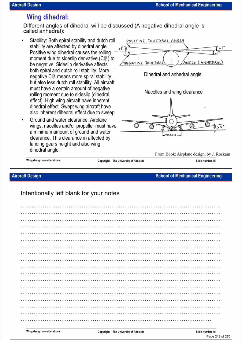
Aircraft Design School of Mechanical Engineering
Wing dihedral:Different angles of dihedral will be discussed (A negative dihedral angle is called anhedral):
• Stability: Both spiral stability and dutch roll stability are affected by dihedral angle. Positive wing dihedral causes the rolling moment due to sideslip derivative (Clβ) to
Dihedral and anhedral angle
Nacelles and wing clearance
moment due to sideslip derivative (Clβ) to be negative. Sideslip derivative affects both spiral and dutch roll stability. More negative Clβ means more spiral stability but also less dutch roll stability. All aircraft must have a certain amount of negative rolling moment due to sideslip (dihedral effect). High wing aircraft have inherent dihedral effect. Swept wing aircraft have also inherent dihedral effect due to sweep.
Wing design considerations I Copyright - The University of Adelaide Slide Number 15
From Book: Airplane design, by J. Roskam
also inherent dihedral effect due to sweep.
• Ground and water clearance: Airplane wings, nacelles and/or propeller must have a minimum amount of ground and water clearance. This clearance in affected by landing gears height and also wing dihedral angle.
Aircraft Design School of Mechanical Engineering
Intentionally left blank for your notes
………………………………………………………………………………………………
………………………………………………………………………………………………
………………………………………………………………………………………………
………………………………………………………………………………………………………………………………………………………………………………………………
………………………………………………………………………………………………
………………………………………………………………………………………………
………………………………………………………………………………………………
………………………………………………………………………………………………
………………………………………………………………………………………………
………………………………………………………………………………………………
………………………………………………………………………………………………
………………………………………………………………………………………………
………………………………………………………………………………………………
Wing design considerations I Copyright - The University of Adelaide Slide Number 16
………………………………………………………………………………………………
………………………………………………………………………………………………
………………………………………………………………………………………………
………………………………………………………………………………………………
………………………………………………………………………………………………
………………………………………………………………………………………….
Page 219 of 270
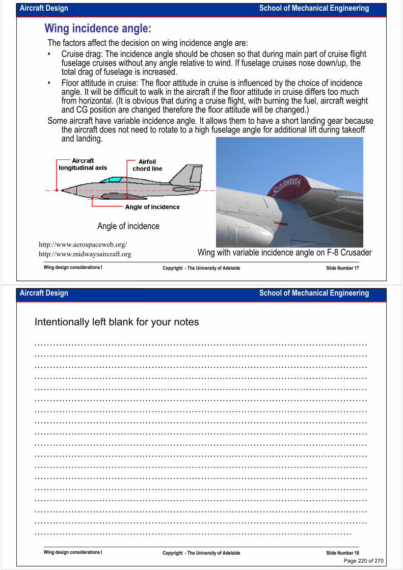
Aircraft Design School of Mechanical Engineering
Wing incidence angle:The factors affect the decision on wing incidence angle are:
• Cruise drag: The incidence angle should be chosen so that during main part of cruise flight fuselage cruises without any angle relative to wind. If fuselage cruises nose down/up, the total drag of fuselage is increased.
• Floor attitude in cruise: The floor attitude in cruise is influenced by the choice of incidence angle. It will be difficult to walk in the aircraft if the floor attitude in cruise differs too much from horizontal. (It is obvious that during a cruise flight, with burning the fuel, aircraft weight angle. It will be difficult to walk in the aircraft if the floor attitude in cruise differs too much from horizontal. (It is obvious that during a cruise flight, with burning the fuel, aircraft weight and CG position are changed therefore the floor attitude will be changed.)
Some aircraft have variable incidence angle. It allows them to have a short landing gear because the aircraft does not need to rotate to a high fuselage angle for additional lift during takeoff and landing.
Wing design considerations I Copyright - The University of Adelaide Slide Number 17
http://www.aerospaceweb.org/
Angle of incidence
http://www.midwaysaircraft.org Wing with variable incidence angle on F-8 Crusader
Aircraft Design School of Mechanical Engineering
Intentionally left blank for your notes
………………………………………………………………………………………………
………………………………………………………………………………………………
………………………………………………………………………………………………
………………………………………………………………………………………………………………………………………………………………………………………………
………………………………………………………………………………………………
………………………………………………………………………………………………
………………………………………………………………………………………………
………………………………………………………………………………………………
………………………………………………………………………………………………
………………………………………………………………………………………………
………………………………………………………………………………………………
………………………………………………………………………………………………
………………………………………………………………………………………………
Wing design considerations I Copyright - The University of Adelaide Slide Number 18
………………………………………………………………………………………………
………………………………………………………………………………………………
………………………………………………………………………………………………
………………………………………………………………………………………………
………………………………………………………………………………………………
………………………………………………………………………………………….
Page 220 of 270

School of Mechanical EngineeringAircraft Design
Wing design considerations II
Dr. MAZIAR ARJOMANDI
Semester I
Wing design considerations II Copyright - The University of Adelaide Slide Number 1
Semester I
Aircraft Design School of Mechanical Engineering
Airfoil families:• The early airfoils mainly designed by trial and error
• The NACA airfoils designed mathematically
• The modern airfoils designed for the specific requirements
– (The best reference is: Theory of wing section by Abbott)
NACA 0012
0 – percent camber
0 – location of max camber
12 – thickness ratio
Airfoil families
Wing design considerations II Copyright - The University of Adelaide Slide Number 2
From Book: Aircraft design, a conceptual approach, by D. Raymer
Page 221 of 270
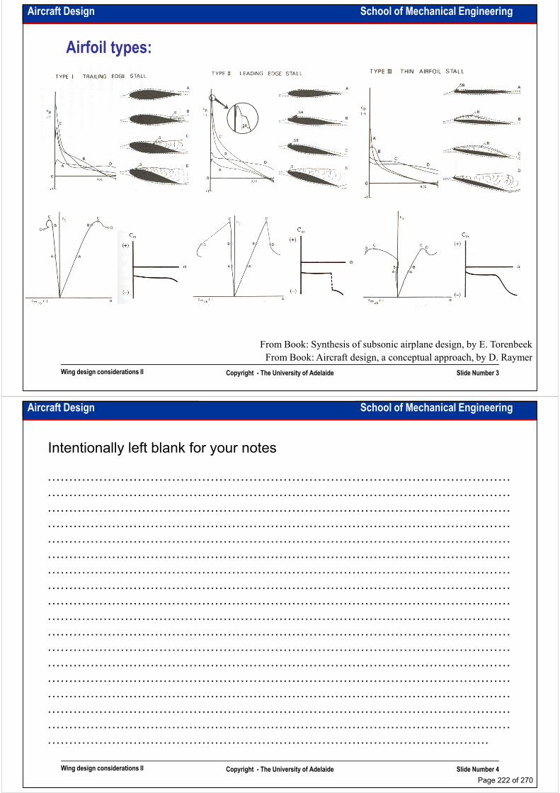
Aircraft Design School of Mechanical Engineering
Airfoil types:
Wing design considerations II Copyright - The University of Adelaide Slide Number 3
From Book: Aircraft design, a conceptual approach, by D. Raymer
From Book: Synthesis of subsonic airplane design, by E. Torenbeek
Aircraft Design School of Mechanical Engineering
Intentionally left blank for your notes
………………………………………………………………………………………………
………………………………………………………………………………………………
………………………………………………………………………………………………
………………………………………………………………………………………………………………………………………………………………………………………………
………………………………………………………………………………………………
………………………………………………………………………………………………
………………………………………………………………………………………………
………………………………………………………………………………………………
………………………………………………………………………………………………
………………………………………………………………………………………………
………………………………………………………………………………………………
………………………………………………………………………………………………
………………………………………………………………………………………………
Wing design considerations II Copyright - The University of Adelaide Slide Number 4
………………………………………………………………………………………………
………………………………………………………………………………………………
………………………………………………………………………………………………
………………………………………………………………………………………………
………………………………………………………………………………………………
………………………………………………………………………………………….
Page 222 of 270

Aircraft Design School of Mechanical Engineering
Which airfoil is better?• For conceptual design work rely on the existing airfoils.
• The first consideration is the “design lift coefficient”. This is the lift coefficient at which the airfoil has the best angle of L/D.
• For conceptual design work we can assume that the “wing design lift coefficient” is equal to the “airfoil design lift coefficient”.
• The “design lift coefficient” can be calculated by: CL=(1/q)(W/S).• The “design lift coefficient” can be calculated by: CL=(1/q)(W/S).
• At the early stages of conceptual design it could be assumed around 0.3-0.5.
• In selecting an airfoil for high subsonic speeds, The critical Mach number should be considered (supercritical airfoils).
• In modern airfoil design it is desirable to maintain the flow laminar over the greatest part of the airfoil.
• Some of the airfoils (especially cambered airfoils) generate considerable pitching moments, which should be considered. These airfoils could be recommended for tailless or canard aircraft.
• At the early stage of design, the airfoil could be selected from the catalogues or even
Wing design considerations II Copyright - The University of Adelaide Slide Number 5
• At the early stage of design, the airfoil could be selected from the catalogues or even similar to the previous successful designs. For more precise design, it will be based on inverse computational solution and further optimisation.
• Airfoil lift coefficient should be corrected for wing (divide it by 1.05 – 1.1 for wing to count interference effect) and also for sweep angle (multiple it by cosΛ3/4). (see slide 9)
Therefore the main parameters which should be considered are: airfoil drag coefficient,
airfoil lift coefficient, airfoil critical Mach number and airfoil pitching moment
Aircraft Design School of Mechanical Engineering
Flaps:
• The following factors affect the decision of flap size and type:
– High lift requirements: The flap type and size should be selected according to The
required values of maximum takeoff and landing lift coefficients, obtained from
sizing calculations.
– Trim considerations: Flaps cause significant changes in pitching moment due to – Trim considerations: Flaps cause significant changes in pitching moment due to
changing the wing camber and changing the downwash on the horizontal tail. To
“trim out” these flap induced pitching moments, considerable down loads may be
required on the horizontal tail. (or it should be bigger). It should be considered that
from a performance point of view only the trimmed lift coefficient can be used in the
calculations not untrimmed.
– Drag considerations: Flap deployment always results in an increase in drag. In the
selection of a flap system, the lift to drag ratio for the takeoff flap down
configuration in an engine out climb (one of the critical configuration for sizing the
Wing design considerations II Copyright - The University of Adelaide Slide Number 6
configuration in an engine out climb (one of the critical configuration for sizing the
aircraft) should be considered. (because of relationship between the flap
deployment and drag incensement, usually the flaps set at lower angle in takeoff
than in landing.
– Cost, complexity and maintenance: The higher is the lift generated by flap system,
the more complex and more expensive they are. Moreover it increases the
maintenance cost and time.
Page 223 of 270

Aircraft Design School of Mechanical Engineering
Flap types:
Wing design considerations II Copyright - The University of Adelaide Slide Number 7
From Book: The anatomy of the
airplane, by D. Stinton
Aircraft Design School of Mechanical Engineering
Intentionally left blank for your notes
………………………………………………………………………………………………
………………………………………………………………………………………………
………………………………………………………………………………………………
………………………………………………………………………………………………………………………………………………………………………………………………
………………………………………………………………………………………………
………………………………………………………………………………………………
………………………………………………………………………………………………
………………………………………………………………………………………………
………………………………………………………………………………………………
………………………………………………………………………………………………
………………………………………………………………………………………………
………………………………………………………………………………………………
………………………………………………………………………………………………
Wing design considerations II Copyright - The University of Adelaide Slide Number 8
………………………………………………………………………………………………
………………………………………………………………………………………………
………………………………………………………………………………………………
………………………………………………………………………………………………
………………………………………………………………………………………………
………………………………………………………………………………………….
Page 224 of 270
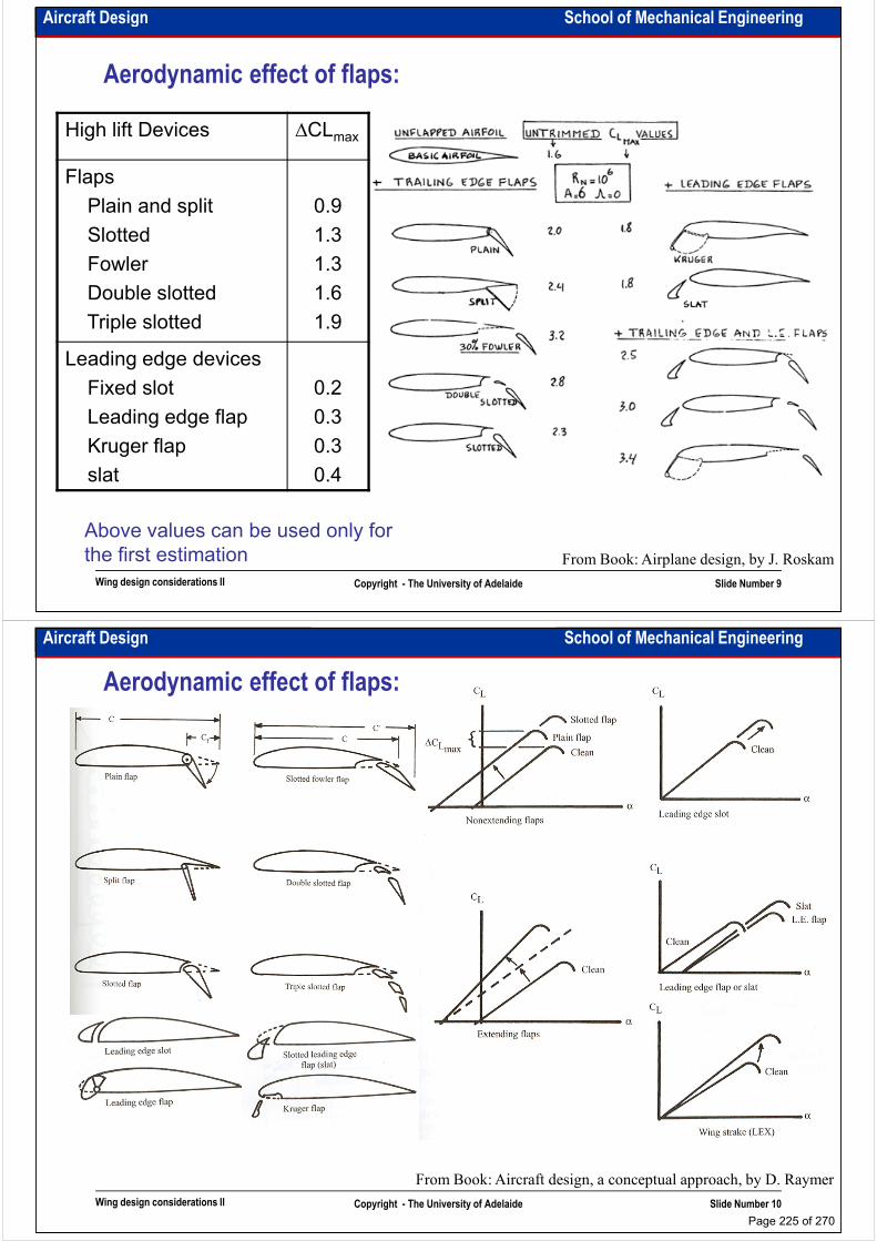
Aircraft Design School of Mechanical Engineering
Aerodynamic effect of flaps:
High lift Devices ∆CLmax
Flaps
Plain and split 0.9Plain and split
Slotted
Fowler
Double slotted
Triple slotted
0.9
1.3
1.3
1.6
1.9
Leading edge devices
Fixed slot
Leading edge flap
0.2
0.3
Wing design considerations II Copyright - The University of Adelaide Slide Number 9
From Book: Airplane design, by J. Roskam
Leading edge flap
Kruger flap
slat
0.3
0.3
0.4
Above values can be used only for
the first estimation
Aircraft Design School of Mechanical Engineering
Aerodynamic effect of flaps:
Wing design considerations II Copyright - The University of Adelaide Slide Number 10
From Book: Aircraft design, a conceptual approach, by D. Raymer
Page 225 of 270
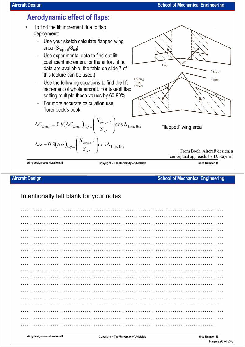
Aircraft Design School of Mechanical Engineering
Aerodynamic effect of flaps:
• To find the lift increment due to flap deployment:
– Use your sketch calculate flapped wing area (Sflapped/Sref).
– Use experimental data to find out lift – Use experimental data to find out lift coefficient increment for the airfoil. (if no data are available, the table on slide 7 of this lecture can be used.)
– Use the following equations to find the lift increment of whole aircraft. For takeoff flap setting multiple these values by 60-80%.
– For more accurate calculation use Torenbeek’s book
Wing design considerations II Copyright - The University of Adelaide Slide Number 11
From Book: Aircraft design, a
conceptual approach, by D. Raymer
“flapped” wing area( )
( ) line hinge
line hingemaxmax
cos9.0
cos9.0
Λ
∆=∆
Λ
∆=∆
ref
flapped
airfoil
ref
flapped
airfoilLL
S
S
S
SCC
αα
Aircraft Design School of Mechanical Engineering
Intentionally left blank for your notes
………………………………………………………………………………………………
………………………………………………………………………………………………
………………………………………………………………………………………………
………………………………………………………………………………………………………………………………………………………………………………………………
………………………………………………………………………………………………
………………………………………………………………………………………………
………………………………………………………………………………………………
………………………………………………………………………………………………
………………………………………………………………………………………………
………………………………………………………………………………………………
………………………………………………………………………………………………
………………………………………………………………………………………………
………………………………………………………………………………………………
Wing design considerations II Copyright - The University of Adelaide Slide Number 12
………………………………………………………………………………………………
………………………………………………………………………………………………
………………………………………………………………………………………………
………………………………………………………………………………………………
………………………………………………………………………………………………
………………………………………………………………………………………….
Page 226 of 270

Aircraft Design School of Mechanical Engineering
Ailerons:• Aerodynamic effect of ailerons is similar to that of
the plain flaps.
• Ailerons loose their effectiveness at high angles of attack.
• Adverse yaw is the negative yawing moment created by the ailerons. To decrease the adverse created by the ailerons. To decrease the adverse yaw we use differential aileron controls or Frise ailerons.
• “Aileron reversal” can be seen on swept aft wings. At high speed (high dynamic pressure) ailerons loos their effectiveness due to lack of torsion stiffness of the wing. Because of that these aircraft usually are equipped by inboard and outboard ailerons and outboard ailerons are locked-in-place on high speeds. (Boeing 707, 727,747 and …)
“Differential” aileron control
Wing design considerations II Copyright - The University of Adelaide Slide Number 13
• The outboard flow on the swept wings tends to become parallel to the aileron hinge line. (In some aircraft to control this flow the fences are used.
• The hinge line and actuating lug positions must be calculated according to aerodynamic centre of the ailerons in order to reduce the loads on pilot’s hand/s From Book: Airplane design, by J. Roskam
“Frise” ailerons
Aircraft Design School of Mechanical Engineering
Spoilers:
• Spoilers spoil the airflow over the part of the surface immediately behind the spoilers (wing area is reduced hence lift is reduced)
• During landing or aborted takeoff, when the flaps are down, spoilers are extremely effective as they interrupt the airflow over the flaps. they interrupt the airflow over the flaps.
• Spoilers can be used for roll control.
• Spoilers generate positive yawing moment –proverse yaw.
• During landing when the flaps are down spoilers are not used but exactly after the first touch with the ground, applying the spoilers extremely increases the aircraft drag and also reduces the lift which increases the break effectiveness.
Wing design considerations II Copyright - The University of Adelaide Slide Number 14
• Spoilers are extremely useful during descent, when an appreciable increment in drag is needed to obtain a high rate of descent.
• In some cases spoilers are called airbrakes (speedbrakes). In this case they are installed on upper and lower surfaces of the wing.
From Book: Airplane design, by J. Roskam
Spoiler
Page 227 of 270
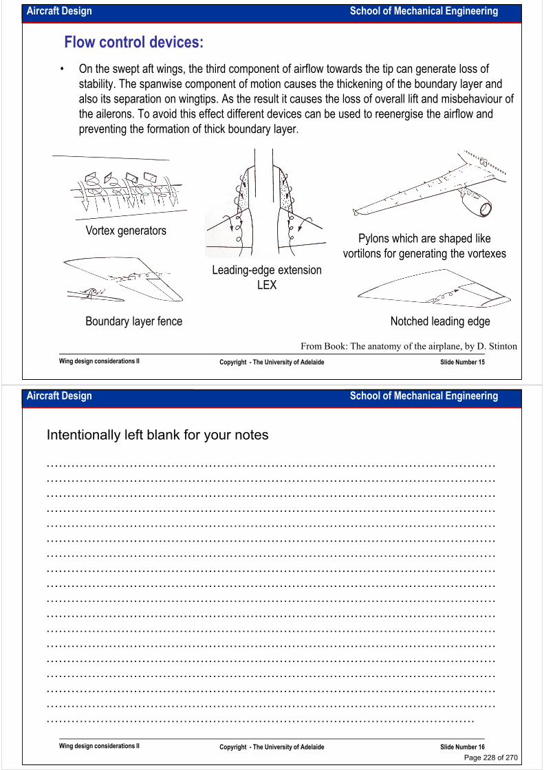
Aircraft Design School of Mechanical Engineering
Flow control devices:
• On the swept aft wings, the third component of airflow towards the tip can generate loss of
stability. The spanwise component of motion causes the thickening of the boundary layer and
also its separation on wingtips. As the result it causes the loss of overall lift and misbehaviour of
the ailerons. To avoid this effect different devices can be used to reenergise the airflow and
preventing the formation of thick boundary layer.preventing the formation of thick boundary layer.
Vortex generatorsPylons which are shaped like
vortilons for generating the vortexes
Wing design considerations II Copyright - The University of Adelaide Slide Number 15
Leading-edge extension
LEX
Boundary layer fence
vortilons for generating the vortexes
Notched leading edge
From Book: The anatomy of the airplane, by D. Stinton
Aircraft Design School of Mechanical Engineering
Intentionally left blank for your notes
………………………………………………………………………………………………
………………………………………………………………………………………………
………………………………………………………………………………………………
………………………………………………………………………………………………………………………………………………………………………………………………
………………………………………………………………………………………………
………………………………………………………………………………………………
………………………………………………………………………………………………
………………………………………………………………………………………………
………………………………………………………………………………………………
………………………………………………………………………………………………
………………………………………………………………………………………………
………………………………………………………………………………………………
………………………………………………………………………………………………
Wing design considerations II Copyright - The University of Adelaide Slide Number 16
………………………………………………………………………………………………
………………………………………………………………………………………………
………………………………………………………………………………………………
………………………………………………………………………………………………
………………………………………………………………………………………………
………………………………………………………………………………………….
Page 228 of 270

Aircraft Design School of Mechanical Engineering
Wing Tips:• For detail see “Aeronautical Engineering I”
Wing design considerations II Copyright - The University of Adelaide Slide Number 17
From Book: Aircraft design, a conceptual approach, by D. Raymer
Aircraft Design School of Mechanical Engineering
Wing structural arrangement:
Definition of major structural wing component
Wing structural arrangement
Boeing 767
Wing design considerations II Copyright - The University of Adelaide Slide Number 18
From Book: Airplane design, by J. Roskam
Boeing 767
Page 229 of 270

Aircraft Design School of Mechanical Engineering
Wing structural arrangement:
Wing cross section DC-10
Wing design considerations II Copyright - The University of Adelaide Slide Number 19
From Book: Airplane design, by J. Roskam
Double slotted and leading
edge flap installation DC-10
Aircraft Design School of Mechanical Engineering
Intentionally left blank for your notes
………………………………………………………………………………………………
………………………………………………………………………………………………
………………………………………………………………………………………………
………………………………………………………………………………………………………………………………………………………………………………………………
………………………………………………………………………………………………
………………………………………………………………………………………………
………………………………………………………………………………………………
………………………………………………………………………………………………
………………………………………………………………………………………………
………………………………………………………………………………………………
………………………………………………………………………………………………
………………………………………………………………………………………………
………………………………………………………………………………………………
Wing design considerations II Copyright - The University of Adelaide Slide Number 20
………………………………………………………………………………………………
………………………………………………………………………………………………
………………………………………………………………………………………………
………………………………………………………………………………………………
………………………………………………………………………………………………
………………………………………………………………………………………….
Page 230 of 270
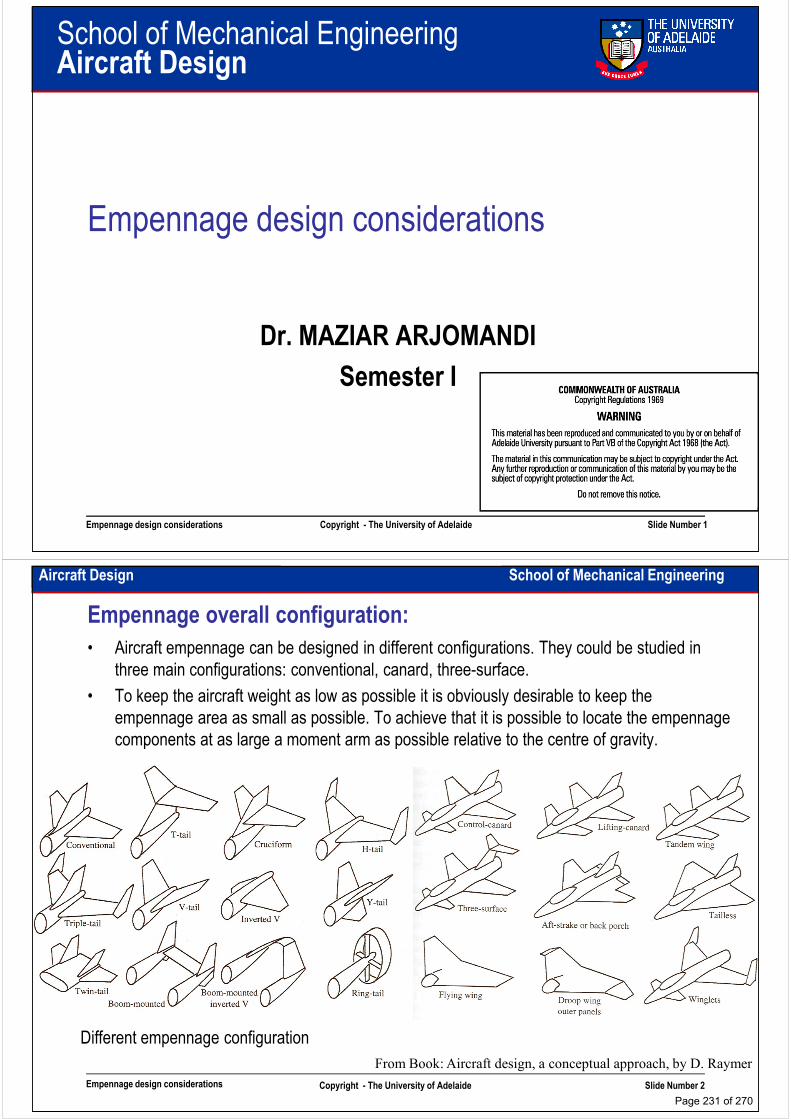
School of Mechanical EngineeringAircraft Design
Empennage design considerations
Dr. MAZIAR ARJOMANDI
Semester I
Empennage design considerations Copyright - The University of Adelaide Slide Number 1
Semester I
Aircraft Design School of Mechanical Engineering
Empennage overall configuration:
• Aircraft empennage can be designed in different configurations. They could be studied in
three main configurations: conventional, canard, three-surface.
• To keep the aircraft weight as low as possible it is obviously desirable to keep the
empennage area as small as possible. To achieve that it is possible to locate the empennage
components at as large a moment arm as possible relative to the centre of gravity.components at as large a moment arm as possible relative to the centre of gravity.
Empennage design considerations Copyright - The University of Adelaide Slide Number 2
From Book: Aircraft design, a conceptual approach, by D. Raymer
Different empennage configuration
Page 231 of 270

Aircraft Design School of Mechanical Engineering
Neutral point and static margin:From Book: The anatomy of the airplane, by D. Stinton
•An aircraft may be uncontrollable in one/two axes but it must be stable in all three axes
(remember the childhood paper planes. They were stable but not controllable)
•A designer should have a good sense and understanding about neutral point (NP) and static
margin (SM).
Power-on,
power-off,
Empennage design considerations Copyright - The University of Adelaide Slide Number 3
power-off,
stick-fix
and
stick free
SM
Aircraft Design School of Mechanical Engineering
Intentionally left blank for your notes
………………………………………………………………………………………………
………………………………………………………………………………………………
………………………………………………………………………………………………
………………………………………………………………………………………………………………………………………………………………………………………………
………………………………………………………………………………………………
………………………………………………………………………………………………
………………………………………………………………………………………………
………………………………………………………………………………………………
………………………………………………………………………………………………
………………………………………………………………………………………………
………………………………………………………………………………………………
………………………………………………………………………………………………
………………………………………………………………………………………………
Empennage design considerations Copyright - The University of Adelaide Slide Number 4
………………………………………………………………………………………………
………………………………………………………………………………………………
………………………………………………………………………………………………
………………………………………………………………………………………………
………………………………………………………………………………………………
………………………………………………………………………………………….
Page 232 of 270
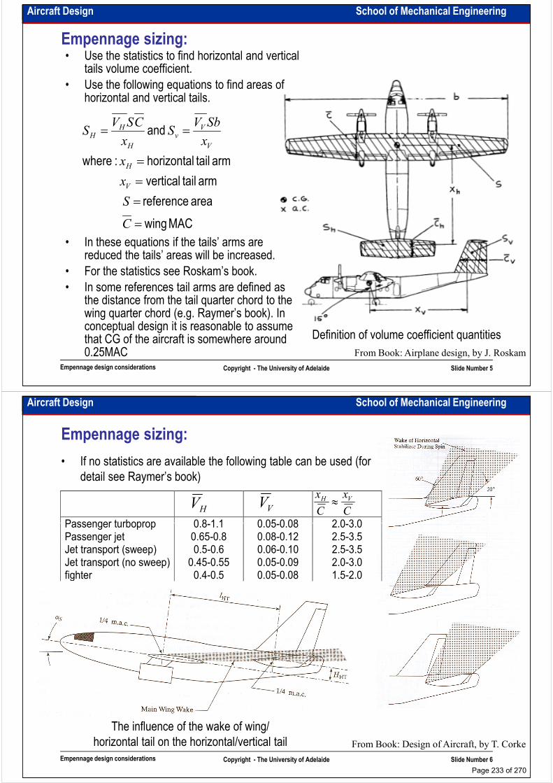
Aircraft Design School of Mechanical Engineering
Empennage sizing:• Use the statistics to find horizontal and vertical
tails volume coefficient.
• Use the following equations to find areas of horizontal and vertical tails.
and ==SbV
SCSV
SV
v
H
H
• In these equations if the tails’ arms are reduced the tails’ areas will be increased.
MAC wing
area reference
arm tail vertical
arm tail horizontal :where
and
=
=
=
=
==
C
S
x
x
xS
xS
V
H
V
v
H
H
Empennage design considerations Copyright - The University of Adelaide Slide Number 5
reduced the tails’ areas will be increased.
• For the statistics see Roskam’s book.
• In some references tail arms are defined as the distance from the tail quarter chord to the wing quarter chord (e.g. Raymer’s book). In conceptual design it is reasonable to assume that CG of the aircraft is somewhere around 0.25MAC From Book: Airplane design, by J. Roskam
Definition of volume coefficient quantities
Aircraft Design School of Mechanical Engineering
Empennage sizing:
• If no statistics are available the following table can be used (for
detail see Raymer’s book)
Passenger turboprop 0.8-1.1 0.05-0.08 2.0-3.0
HV
VV
C
x
C
xVH
≈
Passenger turboprop 0.8-1.1 0.05-0.08 2.0-3.0 Passenger jet 0.65-0.8 0.08-0.12 2.5-3.5 Jet transport (sweep) 0.5-0.6 0.06-0.10 2.5-3.5 Jet transport (no sweep) 0.45-0.55 0.05-0.09 2.0-3.0 fighter 0.4-0.5 0.05-0.08 1.5-2.0
Empennage design considerations Copyright - The University of Adelaide Slide Number 6
From Book: Design of Aircraft, by T. Corke
The influence of the wake of wing/
horizontal tail on the horizontal/vertical tail
Page 233 of 270

Aircraft Design School of Mechanical Engineering
Empennage planform:
• It is recommended to use statistics to find horizontal and vertical tails geometrical specification (e.g. aspect ratio, sweep angle, taper ratio, thickness ratio, dihedral angle, …)
• The tail airfoils are usually symmetrical (e.g. NACA 0009 or 0014). For big jet transport aircraft unsymmetrical and even cambered airfoils can be used. For canards cambered airfoils are usually used.
• Horizontal tail always must stall later than wing and canard always must stall sooner than • Horizontal tail always must stall later than wing and canard always must stall sooner than wing
• Horizontal tail and vertical tail sweep angle should be more than of the wing (critical Mach for them should be about 5% more than critical Mach for the wing)
• Some recommendations:
– Thickness ratio: Horizontal and vertical tails thickness ratio should be 1% or 2% less than of the wing
– Aspect ratio: For high aspect ratio wing, horizontal tail aspect ratio is recommended equal to 3.5-4.5 and for low aspect ratio wing, it is recommended equal to 2-3. Vertical
Empennage design considerations Copyright - The University of Adelaide Slide Number 7
equal to 3.5-4.5 and for low aspect ratio wing, it is recommended equal to 2-3. Vertical tail aspect ratio can be chosen between 0.8-1.2
– Taper ratio: For conventional arrangement, horizontal and vertical tails taper ratio equals 0.3-0.5, For T-tail configuration vertical tail aspect ratio equals 1
The best method is to collect the statistic for each design
Aircraft Design School of Mechanical Engineering
Intentionally left blank for your notes
………………………………………………………………………………………………
………………………………………………………………………………………………
………………………………………………………………………………………………
………………………………………………………………………………………………………………………………………………………………………………………………
………………………………………………………………………………………………
………………………………………………………………………………………………
………………………………………………………………………………………………
………………………………………………………………………………………………
………………………………………………………………………………………………
………………………………………………………………………………………………
………………………………………………………………………………………………
………………………………………………………………………………………………
………………………………………………………………………………………………
Empennage design considerations Copyright - The University of Adelaide Slide Number 8
………………………………………………………………………………………………
………………………………………………………………………………………………
………………………………………………………………………………………………
………………………………………………………………………………………………
………………………………………………………………………………………………
………………………………………………………………………………………….
Page 234 of 270
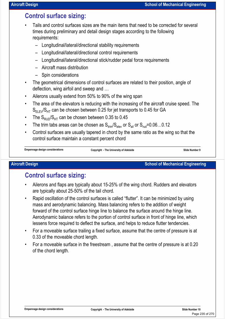
Aircraft Design School of Mechanical Engineering
Control surface sizing:
• Tails and control surfaces sizes are the main items that need to be corrected for several
times during preliminary and detail design stages according to the following
requirements:
– Longitudinal/lateral/directional stability requirements
– Longitudinal/lateral/directional control requirements– Longitudinal/lateral/directional control requirements
– Longitudinal/lateral/directional stick/rudder pedal force requirements
– Aircraft mass distribution
– Spin considerations
• The geometrical dimensions of control surfaces are related to their position, angle of
deflection, wing airfoil and sweep and …
• Ailerons usually extend from 50% to 90% of the wing span
• The area of the elevators is reducing with the increasing of the aircraft cruise speed. The
Empennage design considerations Copyright - The University of Adelaide Slide Number 9
• The area of the elevators is reducing with the increasing of the aircraft cruise speed. The
SELEV/SHT can be chosen between 0.25 for jet transports to 0.45 for GA
• The SRUD/SHT can be chosen between 0.35 to 0.45
• The trim tabs areas can be chosen as Strim/Selev or Sail or Srud=0.06…0.12
• Control surfaces are usually tapered in chord by the same ratio as the wing so that the
control surface maintain a constant percent chord
Aircraft Design School of Mechanical Engineering
Control surface sizing:
• Ailerons and flaps are typically about 15-25% of the wing chord. Rudders and elevators
are typically about 25-50% of the tail chord.
• Rapid oscillation of the control surfaces is called “flutter”. It can be minimized by using
mass and aerodynamic balancing. Mass balancing refers to the addition of weight
forward of the control surface hinge line to balance the surface around the hinge line. forward of the control surface hinge line to balance the surface around the hinge line.
Aerodynamic balance refers to the portion of control surface in front of hinge line, which
lessens force required to deflect the surface, and helps to reduce flutter tendencies.
• For a moveable surface trailing a fixed surface, assume that the centre of pressure is at
0.33 of the moveable chord length.
• For a moveable surface in the freestream , assume that the centre of pressure is at 0.20
of the chord length.
Empennage design considerations Copyright - The University of Adelaide Slide Number 10
Page 235 of 270
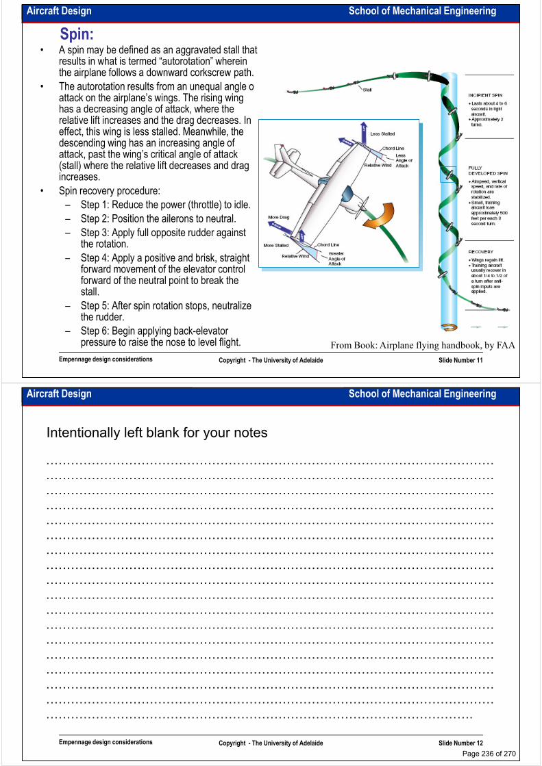
Aircraft Design School of Mechanical Engineering
Spin:• A spin may be defined as an aggravated stall that
results in what is termed “autorotation” wherein the airplane follows a downward corkscrew path.
• The autorotation results from an unequal angle of attack on the airplane’s wings. The rising wing has a decreasing angle of attack, where the relative lift increases and the drag decreases. In effect, this wing is less stalled. Meanwhile, the effect, this wing is less stalled. Meanwhile, the descending wing has an increasing angle of attack, past the wing’s critical angle of attack (stall) where the relative lift decreases and drag increases.
• Spin recovery procedure:
– Step 1: Reduce the power (throttle) to idle.
– Step 2: Position the ailerons to neutral.
– Step 3: Apply full opposite rudder against the rotation.
– Step 4: Apply a positive and brisk, straight
Empennage design considerations Copyright - The University of Adelaide Slide Number 11
– Step 4: Apply a positive and brisk, straight forward movement of the elevator control forward of the neutral point to break the stall.
– Step 5: After spin rotation stops, neutralize the rudder.
– Step 6: Begin applying back-elevator pressure to raise the nose to level flight. From Book: Airplane flying handbook, by FAA
Aircraft Design School of Mechanical Engineering
Intentionally left blank for your notes
………………………………………………………………………………………………
………………………………………………………………………………………………
………………………………………………………………………………………………
………………………………………………………………………………………………………………………………………………………………………………………………
………………………………………………………………………………………………
………………………………………………………………………………………………
………………………………………………………………………………………………
………………………………………………………………………………………………
………………………………………………………………………………………………
………………………………………………………………………………………………
………………………………………………………………………………………………
………………………………………………………………………………………………
………………………………………………………………………………………………
Empennage design considerations Copyright - The University of Adelaide Slide Number 12
………………………………………………………………………………………………
………………………………………………………………………………………………
………………………………………………………………………………………………
………………………………………………………………………………………………
………………………………………………………………………………………………
………………………………………………………………………………………….
Page 236 of 270
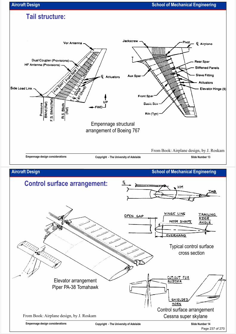
Aircraft Design School of Mechanical Engineering
Tail structure:
Empennage design considerations Copyright - The University of Adelaide Slide Number 13
From Book: Airplane design, by J. Roskam
Empennage structural
arrangement of Boeing 767
Aircraft Design School of Mechanical Engineering
Control surface arrangement:
Elevator arrangement
Typical control surface
cross section
Empennage design considerations Copyright - The University of Adelaide Slide Number 14
From Book: Airplane design, by J. Roskam
Elevator arrangement
Piper PA-38 Tomahawk
Control surface arrangement
Cessna super skylane
Page 237 of 270

Aircraft Design School of Mechanical Engineering
Tab configuration:
Flight controllable trim tab Servo tab
Empennage design considerations Copyright - The University of Adelaide Slide Number 15
From Book: Airplane design, by J. Roskam
Balance tab Tab arrangement
Cessna citation
Aircraft Design School of Mechanical Engineering
Intentionally left blank for your notes
………………………………………………………………………………………………
………………………………………………………………………………………………
………………………………………………………………………………………………
………………………………………………………………………………………………………………………………………………………………………………………………
………………………………………………………………………………………………
………………………………………………………………………………………………
………………………………………………………………………………………………
………………………………………………………………………………………………
………………………………………………………………………………………………
………………………………………………………………………………………………
………………………………………………………………………………………………
………………………………………………………………………………………………
………………………………………………………………………………………………
Empennage design considerations Copyright - The University of Adelaide Slide Number 16
………………………………………………………………………………………………
………………………………………………………………………………………………
………………………………………………………………………………………………
………………………………………………………………………………………………
………………………………………………………………………………………………
………………………………………………………………………………………….
Page 238 of 270
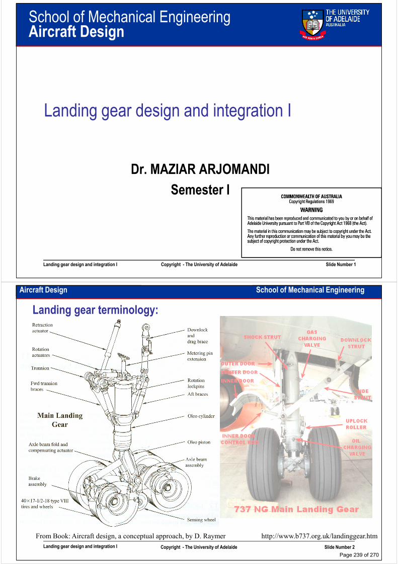
School of Mechanical EngineeringAircraft Design
Landing gear design and integration I
Dr. MAZIAR ARJOMANDI
Semester I
Landing gear design and integration I Copyright - The University of Adelaide Slide Number 1
Semester I
Aircraft Design School of Mechanical Engineering
Landing gear terminology:
Landing gear design and integration I Copyright - The University of Adelaide Slide Number 2
http://www.b737.org.uk/landinggear.htmFrom Book: Aircraft design, a conceptual approach, by D. Raymer
Page 239 of 270
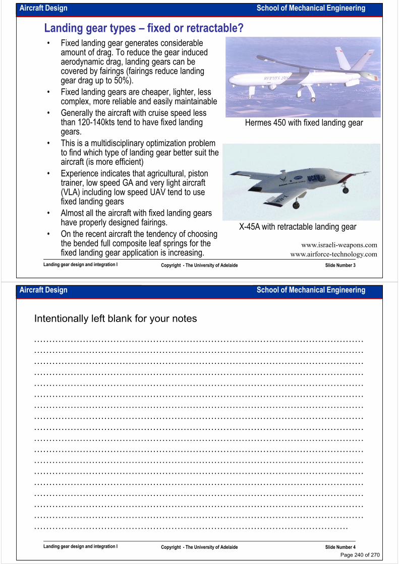
Aircraft Design School of Mechanical Engineering
Landing gear types – fixed or retractable?• Fixed landing gear generates considerable
amount of drag. To reduce the gear induced aerodynamic drag, landing gears can be covered by fairings (fairings reduce landing gear drag up to 50%).
• Fixed landing gears are cheaper, lighter, less • Fixed landing gears are cheaper, lighter, less complex, more reliable and easily maintainable
• Generally the aircraft with cruise speed less than 120-140kts tend to have fixed landing gears.
• This is a multidisciplinary optimization problem to find which type of landing gear better suit the aircraft (is more efficient)
• Experience indicates that agricultural, piston trainer, low speed GA and very light aircraft
Hermes 450 with fixed landing gear
Landing gear design and integration I Copyright - The University of Adelaide Slide Number 3
trainer, low speed GA and very light aircraft (VLA) including low speed UAV tend to use fixed landing gears
• Almost all the aircraft with fixed landing gears have properly designed fairings.
• On the recent aircraft the tendency of choosing the bended full composite leaf springs for the fixed landing gear application is increasing.
www.israeli-weapons.com
www.airforce-technology.com
X-45A with retractable landing gear
Aircraft Design School of Mechanical Engineering
Intentionally left blank for your notes
………………………………………………………………………………………………
………………………………………………………………………………………………
………………………………………………………………………………………………
………………………………………………………………………………………………………………………………………………………………………………………………
………………………………………………………………………………………………
………………………………………………………………………………………………
………………………………………………………………………………………………
………………………………………………………………………………………………
………………………………………………………………………………………………
………………………………………………………………………………………………
………………………………………………………………………………………………
………………………………………………………………………………………………
………………………………………………………………………………………………
Landing gear design and integration I Copyright - The University of Adelaide Slide Number 4
………………………………………………………………………………………………
………………………………………………………………………………………………
………………………………………………………………………………………………
………………………………………………………………………………………………
………………………………………………………………………………………………
………………………………………………………………………………………….
Page 240 of 270

Aircraft Design School of Mechanical Engineering
Landing gear arrangements:
• The “single main” gear has one main gear fore or aft of CG with the auxiliary wheels at the tail and wingtips.
• “Bicycle” arrangement has two main wheels, for and aft of CG with small outrigger wheels.outrigger wheels.
• The “tail dragger” landing gear has two main wheels forward of CG and an auxiliary wheel at the tail.
• “Tricycle” arrangement has two main wheels aft of CG and an auxiliary wheel forward (nose wheel) of CG.
• “Quadricycle” is like bicycle arrangement but with wheels at the side of fuselage.
Landing gear design and integration I Copyright - The University of Adelaide Slide Number 5
• The “multi-bogey” gear has multiple wheels in bicycle arrangement
• The other types of landing gears like droppable gears, air cushions, air bags and skids have rare and specific application. From Book: Aircraft design, a conceptual
approach, by D. Raymer
Landing gear arrangements
Aircraft Design School of Mechanical Engineering
Landing gear arrangements:• Single main gear is used for many sail planes because of its
simplicity.
• Bicycle gear is used on aircraft with narrow fuselage and wide wing span. (aircraft must land and takeoff in a flat attitude with high lift at low angles of attack.)
• Tail dragger was the most widely used arrangement on the early aircraft. It provides more propeller clearance, generates less drag,
U-2 – single main gear• Tail dragger was the most widely used arrangement on the early
aircraft. It provides more propeller clearance, generates less drag, more suitable for rough surfaces and allows wing to generate more lift during takeoff. However it is inherently unstable. If the aircraft starts to turn, the location of the CG behind the main gear causes the turn to get tighter. Moreover tailwheel configuration provides poor visibility over the nose during ground operation.
B-47 – bicycle gear
Landing gear design and integration I Copyright - The University of Adelaide Slide Number 6
http://aerospaceweb.org
DC-3 Dakota – tail dragger
www.radiojerry.com
From Book: Airplane design, by J. Roskam
Ground loop characteristics
of the tailwheel gear
Page 241 of 270
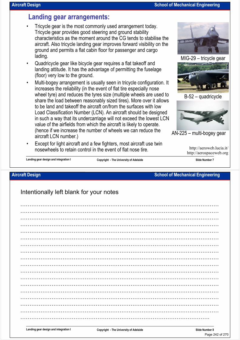
Aircraft Design School of Mechanical Engineering
Landing gear arrangements:
• Tricycle gear is the most commonly used arrangement today. Tricycle gear provides good steering and ground stability characteristics as the moment around the CG tends to stabilise the aircraft. Also tricycle landing gear improves forward visibility on the ground and permits a flat cabin floor for passenger and cargo lading. MIG-29 – tricycle gearlading.
• Quadricycle gear like bicycle gear requires a flat takeoff and landing attitude. It has the advantage of permitting the fuselage (floor) very low to the ground.
• Multi-bogey arrangement is usually seen in tricycle configuration. It increases the reliability (in the event of flat tire especially nose wheel tyre) and reduces the tyres size (multiple wheels are used to share the load between reasonably sized tires). More over it allows to be land and takeoff the aircraft on/from the surfaces with low Load Classification Number (LCN). An aircraft should be designed
B-52 – quadricycle
gear
MIG-29 – tricycle gear
Landing gear design and integration I Copyright - The University of Adelaide Slide Number 7
Load Classification Number (LCN). An aircraft should be designed in such a way that its undercarriage will not exceed the lowest LCN value of the airfields from which the aircraft is likely to operate. (hence if we increase the number of wheels we can reduce the aircraft LCN number.)
• Except for light aircraft and a few fighters, most aircraft use twin nosewheels to retain control in the event of flat nose tire.
http://aerospaceweb.orghttp://aeroweb.lucia.it/
AN-225 – multi-bogey gear
Aircraft Design School of Mechanical Engineering
Intentionally left blank for your notes
………………………………………………………………………………………………
………………………………………………………………………………………………
………………………………………………………………………………………………
………………………………………………………………………………………………………………………………………………………………………………………………
………………………………………………………………………………………………
………………………………………………………………………………………………
………………………………………………………………………………………………
………………………………………………………………………………………………
………………………………………………………………………………………………
………………………………………………………………………………………………
………………………………………………………………………………………………
………………………………………………………………………………………………
………………………………………………………………………………………………
Landing gear design and integration I Copyright - The University of Adelaide Slide Number 8
………………………………………………………………………………………………
………………………………………………………………………………………………
………………………………………………………………………………………………
………………………………………………………………………………………………
………………………………………………………………………………………………
………………………………………………………………………………………….
Page 242 of 270
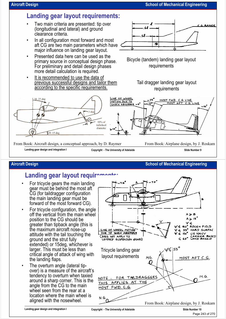
Aircraft Design School of Mechanical Engineering
Landing gear layout requirements:• Two main criteria are presented: tip over
(longitudinal and lateral) and ground clearance criteria.
• In all configuration most forward and most aft CG are two main parameters which have major influence on landing gear layout.
• Presented data here can be used as the • Presented data here can be used as the primary source in conceptual design phase. For preliminary and detail design phases more detail calculation is required.
• It is recommended to use the data of previous successful designs and tailor them according to the specific requirements.
Bicycle (tandem) landing gear layout
requirements
Tail dragger landing gear layout
requirements
Landing gear design and integration I Copyright - The University of Adelaide Slide Number 9
From Book: Airplane design, by J. RoskamFrom Book: Aircraft design, a conceptual approach, by D. Raymer
Aircraft Design School of Mechanical Engineering
• For tricycle gears the main landing gear must be behind the most aft CG (for taildragger configuration the main landing gear must be forward of the most forward CG).
• For tricycle configuration, the angle off the vertical from the main wheel
Landing gear layout requirements:
off the vertical from the main wheel position to the CG should be greater than tipback angle (this is the maximum aircraft nose-up attitude with the tail touching the ground and the strut fully extended) or 15deg, whichever is larger. This must be less than critical angle of attack of wing with the landing flaps.
• The overturn angle (lateral tip-
Tricycle landing gear
layout requirements
Landing gear design and integration I Copyright - The University of Adelaide Slide Number 10
• The overturn angle (lateral tip-over) is a measure of the aircraft’s tendency to overturn when taxied around a sharp corner. This is the angle from the CG to the main wheel seen from the rear at a location where the main wheel is aligned with the nosewheel.
From Book: Airplane design, by J. Roskam
Page 243 of 270

Aircraft Design School of Mechanical Engineering
• Any water-spray or rock-drops caused by the tires especially nosewheel tire must not enter the engine inlets. (FOD: Foreign Object Damage)
• Wheel base and Wheel track are two main parameters (see Aeronautical
Landing gear layout requirements:
main parameters (see Aeronautical Engineering I) that should be calculated according to the mentioned requirements.
Critical angles for FOD in jet engines
Landing gear design and integration I Copyright - The University of Adelaide Slide Number 11
From Book: Airplane design, by J. Roskam
Longitudinal and lateral ground
clearance for gear placement
Aircraft Design School of Mechanical Engineering
Intentionally left blank for your notes
………………………………………………………………………………………………
………………………………………………………………………………………………
………………………………………………………………………………………………
………………………………………………………………………………………………………………………………………………………………………………………………
………………………………………………………………………………………………
………………………………………………………………………………………………
………………………………………………………………………………………………
………………………………………………………………………………………………
………………………………………………………………………………………………
………………………………………………………………………………………………
………………………………………………………………………………………………
………………………………………………………………………………………………
………………………………………………………………………………………………
Landing gear design and integration I Copyright - The University of Adelaide Slide Number 12
………………………………………………………………………………………………
………………………………………………………………………………………………
………………………………………………………………………………………………
………………………………………………………………………………………………
………………………………………………………………………………………………
………………………………………………………………………………………….
Page 244 of 270
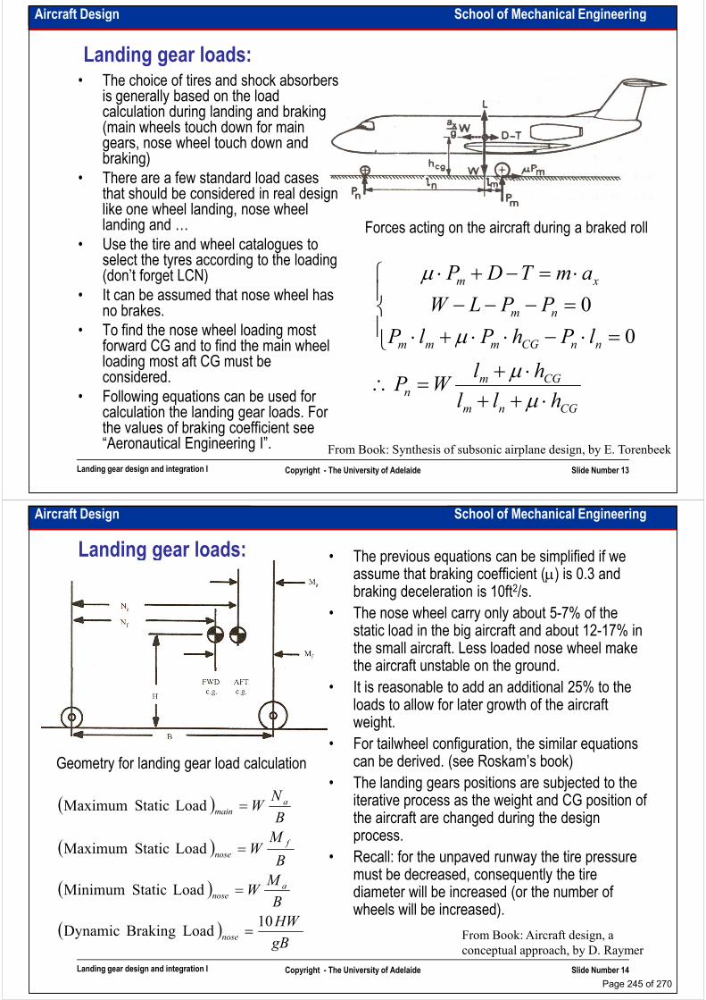
Aircraft Design School of Mechanical Engineering
Landing gear loads:• The choice of tires and shock absorbers
is generally based on the load calculation during landing and braking (main wheels touch down for main gears, nose wheel touch down and braking)
• There are a few standard load cases • There are a few standard load cases that should be considered in real design like one wheel landing, nose wheel landing and …
• Use the tire and wheel catalogues to select the tyres according to the loading (don’t forget LCN)
• It can be assumed that nose wheel has no brakes.
• To find the nose wheel loading most
Forces acting on the aircraft during a braked roll
nm
xm
lPhPlP
PPLW
amTDP
=⋅−⋅⋅+⋅
=−−−
⋅=−+⋅
µ
µ
0
0
Landing gear design and integration I Copyright - The University of Adelaide Slide Number 13
• To find the nose wheel loading most forward CG and to find the main wheel loading most aft CG must be considered.
• Following equations can be used for calculation the landing gear loads. For the values of braking coefficient see “Aeronautical Engineering I”. From Book: Synthesis of subsonic airplane design, by E. Torenbeek
CGnm
CGmn
nnCGmmm
hll
hlWP
lPhPlP
⋅++⋅+
=∴
=⋅−⋅⋅+⋅
µµ
µ 0
Aircraft Design School of Mechanical Engineering
Landing gear loads: • The previous equations can be simplified if we assume that braking coefficient (µ) is 0.3 and braking deceleration is 10ft2/s.
• The nose wheel carry only about 5-7% of the static load in the big aircraft and about 12-17% in the small aircraft. Less loaded nose wheel make the aircraft unstable on the ground.the aircraft unstable on the ground.
• It is reasonable to add an additional 25% to the loads to allow for later growth of the aircraft weight.
• For tailwheel configuration, the similar equations can be derived. (see Roskam’s book)
• The landing gears positions are subjected to the iterative process as the weight and CG position of the aircraft are changed during the design process.
Geometry for landing gear load calculation
( )
M
B
NW a
mainLoad Static Maximum =
Landing gear design and integration I Copyright - The University of Adelaide Slide Number 14
process.
• Recall: for the unpaved runway the tire pressure must be decreased, consequently the tire diameter will be increased (or the number of wheels will be increased).
From Book: Aircraft design, a
conceptual approach, by D. Raymer
( )
( )
( )gB
HW
B
MW
B
MW
nose
anose
f
nose
10Load Braking Dynamic
Load Static Minimum
Load Static Maximum
=
=
=
Page 245 of 270
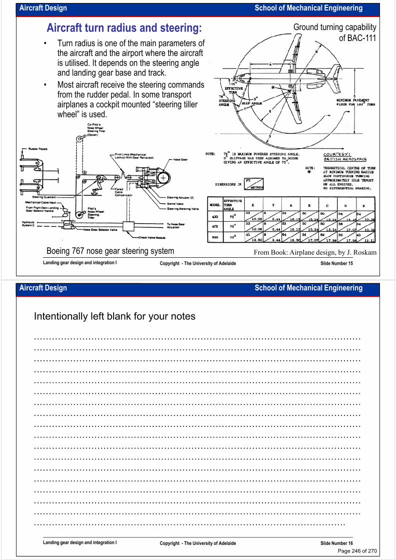
Aircraft Design School of Mechanical Engineering
• Turn radius is one of the main parameters of the aircraft and the airport where the aircraft is utilised. It depends on the steering angle and landing gear base and track.
• Most aircraft receive the steering commands from the rudder pedal. In some transport
Ground turning capability
of BAC-111Aircraft turn radius and steering:
from the rudder pedal. In some transport airplanes a cockpit mounted “steering tiller wheel” is used.
Landing gear design and integration I Copyright - The University of Adelaide Slide Number 15
From Book: Airplane design, by J. RoskamBoeing 767 nose gear steering system
Aircraft Design School of Mechanical Engineering
Intentionally left blank for your notes
………………………………………………………………………………………………
………………………………………………………………………………………………
………………………………………………………………………………………………
………………………………………………………………………………………………………………………………………………………………………………………………
………………………………………………………………………………………………
………………………………………………………………………………………………
………………………………………………………………………………………………
………………………………………………………………………………………………
………………………………………………………………………………………………
………………………………………………………………………………………………
………………………………………………………………………………………………
………………………………………………………………………………………………
………………………………………………………………………………………………
Landing gear design and integration I Copyright - The University of Adelaide Slide Number 16
………………………………………………………………………………………………
………………………………………………………………………………………………
………………………………………………………………………………………………
………………………………………………………………………………………………
………………………………………………………………………………………………
………………………………………………………………………………………….
Page 246 of 270
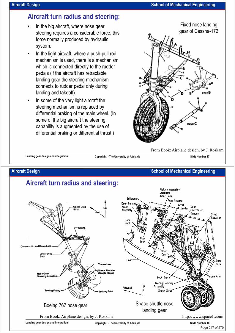
Aircraft Design School of Mechanical Engineering
Aircraft turn radius and steering:
• In the big aircraft, where nose gear
steering requires a considerable force, this
force normally produced by hydraulic
system.
• In the light aircraft, where a push-pull rod
Fixed nose landing
gear of Cessna-172
• In the light aircraft, where a push-pull rod
mechanism is used, there is a mechanism
which is connected directly to the rudder
pedals (if the aircraft has retractable
landing gear the steering mechanism
connects to rudder pedal only during
landing and takeoff)
• In some of the very light aircraft the
steering mechanism is replaced by
Landing gear design and integration I Copyright - The University of Adelaide Slide Number 17
differential braking of the main wheel. (In
some of the big aircraft the steering
capability is augmented by the use of
differential braking or differential thrust.)
From Book: Airplane design, by J. Roskam
Aircraft Design School of Mechanical Engineering
Aircraft turn radius and steering:
Landing gear design and integration I Copyright - The University of Adelaide Slide Number 18
http://www.space1.com/
Space shuttle nose
landing gearBoeing 767 nose gear
From Book: Airplane design, by J. Roskam
Page 247 of 270
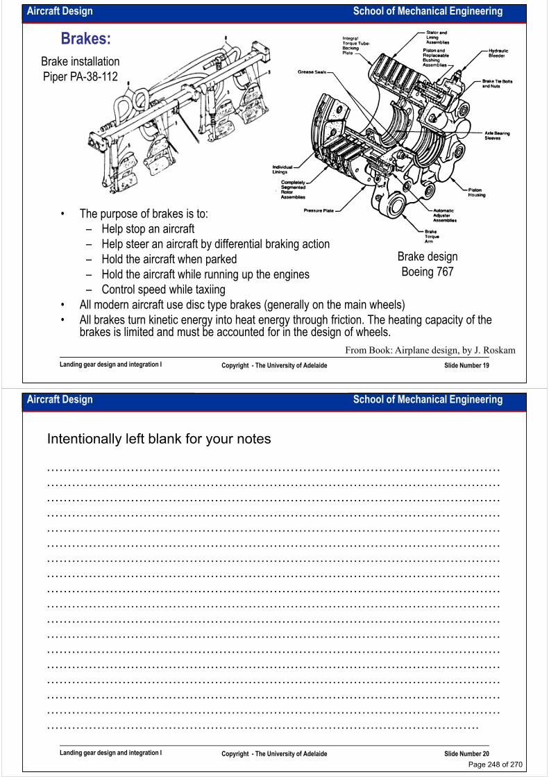
Aircraft Design School of Mechanical Engineering
Brakes:
Brake installation
Piper PA-38-112
• The purpose of brakes is to:
– Help stop an aircraft
– Help steer an aircraft by differential braking action
– Hold the aircraft when parked Brake design
Landing gear design and integration I Copyright - The University of Adelaide Slide Number 19
– Hold the aircraft when parked
– Hold the aircraft while running up the engines
– Control speed while taxiing
• All modern aircraft use disc type brakes (generally on the main wheels)
• All brakes turn kinetic energy into heat energy through friction. The heating capacity of the brakes is limited and must be accounted for in the design of wheels.
From Book: Airplane design, by J. Roskam
Brake design
Boeing 767
Aircraft Design School of Mechanical Engineering
Intentionally left blank for your notes
………………………………………………………………………………………………
………………………………………………………………………………………………
………………………………………………………………………………………………
………………………………………………………………………………………………………………………………………………………………………………………………
………………………………………………………………………………………………
………………………………………………………………………………………………
………………………………………………………………………………………………
………………………………………………………………………………………………
………………………………………………………………………………………………
………………………………………………………………………………………………
………………………………………………………………………………………………
………………………………………………………………………………………………
………………………………………………………………………………………………
Landing gear design and integration I Copyright - The University of Adelaide Slide Number 20
………………………………………………………………………………………………
………………………………………………………………………………………………
………………………………………………………………………………………………
………………………………………………………………………………………………
………………………………………………………………………………………………
………………………………………………………………………………………….
Page 248 of 270
School of Mechanical EngineeringAircraft Design
Landing gear design and integration II
Dr. MAZIAR ARJOMANDI
Semester I
Landing gear design and integration II Copyright - The University of Adelaide Slide Number 1
Semester I
Aircraft Design School of Mechanical Engineering
Tyres:
• Tyres are classified by:
– Ply rating
– Maximum allowable static loading
– Recommended (unloaded) inflation pressure
– Maximum allowable runway speed
• The main types of tyres are:• The main types of tyres are:
– Type III: used for most piston-engined aircraft, has a wide tread and low internal pressure.
– Type VII: used for most jet aircraft, operate under higher internal pressure, which reduces their size.
– Type VIII (New Design): designed for specific requirements.
• To choose a tyre for a specific design, use the Tyre deflection and contact area
Landing gear design and integration II Copyright - The University of Adelaide Slide Number 2
• To choose a tyre for a specific design, use the manufacturers’ catalogues after calculation of maximum allowable static loading, compatible with the allowable values determined from a runway surface viewpoint.
• In specific cases the tyre diameter can be reduced by increasing the number of plies (consequently the internal pressure is increased)
From Book: Aircraft design, a
conceptual approach, by D. Raymer
Tyre deflection and contact area
Page 249 of 270
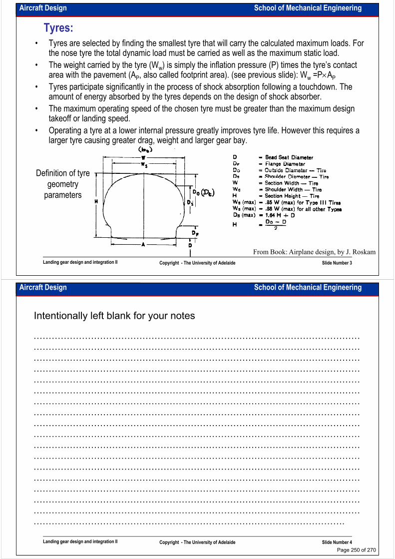
Aircraft Design School of Mechanical Engineering
Tyres:
• Tyres are selected by finding the smallest tyre that will carry the calculated maximum loads. For the nose tyre the total dynamic load must be carried as well as the maximum static load.
• The weight carried by the tyre (Ww) is simply the inflation pressure (P) times the tyre’s contact area with the pavement (AP, also called footprint area). (see previous slide): Ww =P×AP
• Tyres participate significantly in the process of shock absorption following a touchdown. The amount of energy absorbed by the tyres depends on the design of shock absorber.
Definition of tyre
geometry
amount of energy absorbed by the tyres depends on the design of shock absorber.
• The maximum operating speed of the chosen tyre must be greater than the maximum design takeoff or landing speed.
• Operating a tyre at a lower internal pressure greatly improves tyre life. However this requires a larger tyre causing greater drag, weight and larger gear bay.
Landing gear design and integration II Copyright - The University of Adelaide Slide Number 3
From Book: Airplane design, by J. Roskam
geometry
parameters
Aircraft Design School of Mechanical Engineering
Intentionally left blank for your notes
………………………………………………………………………………………………
………………………………………………………………………………………………
………………………………………………………………………………………………
………………………………………………………………………………………………………………………………………………………………………………………………
………………………………………………………………………………………………
………………………………………………………………………………………………
………………………………………………………………………………………………
………………………………………………………………………………………………
………………………………………………………………………………………………
………………………………………………………………………………………………
………………………………………………………………………………………………
………………………………………………………………………………………………
………………………………………………………………………………………………
Landing gear design and integration II Copyright - The University of Adelaide Slide Number 4
………………………………………………………………………………………………
………………………………………………………………………………………………
………………………………………………………………………………………………
………………………………………………………………………………………………
………………………………………………………………………………………………
………………………………………………………………………………………….
Page 250 of 270
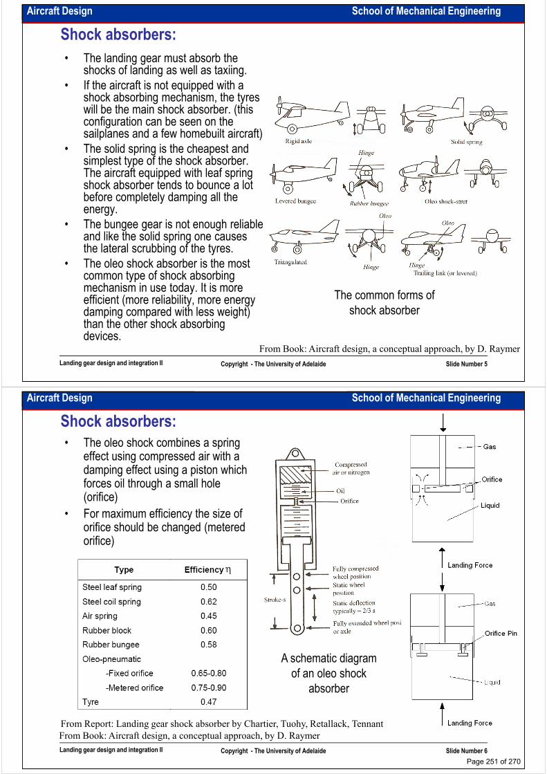
Aircraft Design School of Mechanical Engineering
Shock absorbers:
• The landing gear must absorb the shocks of landing as well as taxiing.
• If the aircraft is not equipped with a shock absorbing mechanism, the tyres will be the main shock absorber. (this configuration can be seen on the sailplanes and a few homebuilt aircraft)sailplanes and a few homebuilt aircraft)
• The solid spring is the cheapest and simplest type of the shock absorber. The aircraft equipped with leaf spring shock absorber tends to bounce a lot before completely damping all the energy.
• The bungee gear is not enough reliable and like the solid spring one causes the lateral scrubbing of the tyres.
• The oleo shock absorber is the most
Landing gear design and integration II Copyright - The University of Adelaide Slide Number 5
• The oleo shock absorber is the most common type of shock absorbing mechanism in use today. It is more efficient (more reliability, more energy damping compared with less weight) than the other shock absorbing devices.
From Book: Aircraft design, a conceptual approach, by D. Raymer
The common forms of
shock absorber
Aircraft Design School of Mechanical Engineering
Shock absorbers:
• The oleo shock combines a spring effect using compressed air with a damping effect using a piston which forces oil through a small hole (orifice)
• For maximum efficiency the size of • For maximum efficiency the size of orifice should be changed (metered orifice)
Landing gear design and integration II Copyright - The University of Adelaide Slide Number 6
From Book: Aircraft design, a conceptual approach, by D. Raymer
A schematic diagram
of an oleo shock
absorber
From Report: Landing gear shock absorber by Chartier, Tuohy, Retallack, Tennant
Page 251 of 270
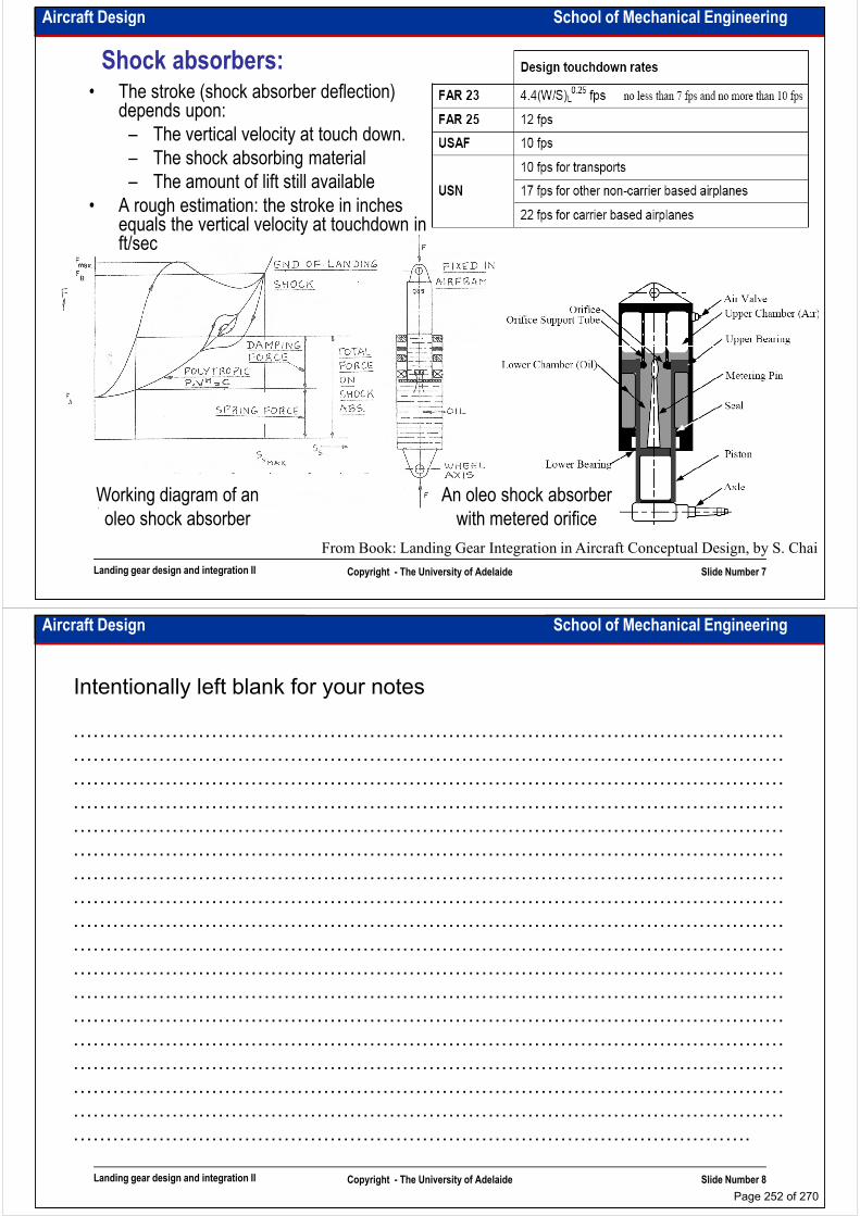
Aircraft Design School of Mechanical Engineering
Shock absorbers:• The stroke (shock absorber deflection)
depends upon:
– The vertical velocity at touch down.
– The shock absorbing material
– The amount of lift still available
• A rough estimation: the stroke in inches • A rough estimation: the stroke in inches equals the vertical velocity at touchdown in ft/sec
Landing gear design and integration II Copyright - The University of Adelaide Slide Number 7
From Book: Landing Gear Integration in Aircraft Conceptual Design, by S. Chai
An oleo shock absorber
with metered orifice
Working diagram of an
oleo shock absorber
Aircraft Design School of Mechanical Engineering
Intentionally left blank for your notes
………………………………………………………………………………………………
………………………………………………………………………………………………
………………………………………………………………………………………………
………………………………………………………………………………………………………………………………………………………………………………………………
………………………………………………………………………………………………
………………………………………………………………………………………………
………………………………………………………………………………………………
………………………………………………………………………………………………
………………………………………………………………………………………………
………………………………………………………………………………………………
………………………………………………………………………………………………
………………………………………………………………………………………………
………………………………………………………………………………………………
Landing gear design and integration II Copyright - The University of Adelaide Slide Number 8
………………………………………………………………………………………………
………………………………………………………………………………………………
………………………………………………………………………………………………
………………………………………………………………………………………………
………………………………………………………………………………………………
………………………………………………………………………………………….
Page 252 of 270
Aircraft Design School of Mechanical Engineering
Shock absorber equations:• The maximum kinetic energy which needs to be
absorbed is:
• It is assumed that the entire touch-down kinetic energy is absorbed by the main landing gear. The energy is absorbed by the tyres and shock absorbers. If the energy were absorbed perfectly,
( ) ( )
landing
absorbedvertical
TTabsorbed
vertical
landing
vertical
W
KEKE
LSLSKE
Vg
WKE
ηη
=
=
+=
=
1
2
1
2
2
:then and;
tireabsorber shock
absorbers. If the energy were absorbed perfectly, the energy absorbed by deflection would be the load times the deflection.
• Landing gear load factor is the ratio of maximum load per leg to the maximum static load per leg (or the average total load summed for all of the shock absorbers divided by the landing weight). It is also called the vertical deceleration rate. The gear load factor is the criterion for measurement of the amount of the loads passing to the structure, payload, crew and passengers. (whether an
( ) ( )
TT
gear
vertical
landinggear
TT
vertical
landing
SNg
V
WLN
LSLS
Vg
W
ηη
η
ηη
−=
=
+
=
2
2
1
2
2
S
:then if
tireabsorber shock
Suggested landing gear load factor
Landing gear design and integration II Copyright - The University of Adelaide Slide Number 9
payload, crew and passengers. (whether an aircraft is comfort or not in landing). The recommended values for Ngear are:
• Using all these equations we can find the total stroke of the landing gear (tyre + shock absorber). About 3cm should be added to the stroke as a safety margin.
Suggested landing gear load factor
Aircraft type Ngear
FAR 23 FAR 25 Fighters and trainers Military transport
3.0 1.5-2.0 3.0-8.0 1.5-2.0
Aircraft Design School of Mechanical Engineering
Intentionally left blank for your notes
………………………………………………………………………………………………
………………………………………………………………………………………………
………………………………………………………………………………………………
………………………………………………………………………………………………………………………………………………………………………………………………
………………………………………………………………………………………………
………………………………………………………………………………………………
………………………………………………………………………………………………
………………………………………………………………………………………………
………………………………………………………………………………………………
………………………………………………………………………………………………
………………………………………………………………………………………………
………………………………………………………………………………………………
………………………………………………………………………………………………
Landing gear design and integration II Copyright - The University of Adelaide Slide Number 10
………………………………………………………………………………………………
………………………………………………………………………………………………
………………………………………………………………………………………………
………………………………………………………………………………………………
………………………………………………………………………………………………
………………………………………………………………………………………….
Page 253 of 270

Aircraft Design School of Mechanical Engineering
Strut-wheel combination and oleo sizing:• The actual dimensions of an oleo depends upon the
strut-wheel combination layout: telescopic, articulated, semi-articulated.
• The static position is about 84% of stroke above the fully extended position for large transport aircraft, 60% for general aviation aircraft and about 66% for other types. general aviation aircraft and about 66% for other types.
• The total length of the oleo including the stroke distance and the fixed portion of oleo will be approximately 2.5-3 times the stroke.
• The nosewheel oleo load is the sum of the static and dynamic loads due to braking while the mainwheel oleo is under only the static load.
• The different combination of strut-wheel can be chosen to reduce the oleo load. This is a multidisciplinary optimisation problem that needs to be iterated for a new
Landing gear design and integration II Copyright - The University of Adelaide Slide Number 11
optimisation problem that needs to be iterated for a new design.
• The oleo diameter is depended on its internal pressure. The diameter of the typical oleos can be found by the following equation if Loleo is load on the oleo:
From Book: Airplane design, by J. RoskamπpL
D oleooleo
43.1=
Aircraft Design School of Mechanical Engineering
Intentionally left blank for your notes
………………………………………………………………………………………………
………………………………………………………………………………………………
………………………………………………………………………………………………
………………………………………………………………………………………………………………………………………………………………………………………………
………………………………………………………………………………………………
………………………………………………………………………………………………
………………………………………………………………………………………………
………………………………………………………………………………………………
………………………………………………………………………………………………
………………………………………………………………………………………………
………………………………………………………………………………………………
………………………………………………………………………………………………
………………………………………………………………………………………………
Landing gear design and integration II Copyright - The University of Adelaide Slide Number 12
………………………………………………………………………………………………
………………………………………………………………………………………………
………………………………………………………………………………………………
………………………………………………………………………………………………
………………………………………………………………………………………………
………………………………………………………………………………………….
Page 254 of 270

Aircraft Design School of Mechanical Engineering
Solid-sprig gear sizing:Deflection geometry
for a solid-spring leg
( )2gearS NWF =
• In this configuration wheel is vertical when it is under static loading.
• It is assumed that the gear leg is not tapered and there are two legs:
( )θsinSFF =
( )
EI
Fly
yS
eq. beamBending3
sin
3
θ
−←=
=
• In this configuration wheel is vertical when it is under static loading.
• It is assumed that the gear leg is not tapered and there are two legs:
Landing gear design and integration II Copyright - The University of Adelaide Slide Number 13
From Book: Aircraft design, a
conceptual approach, by D. Raymer
( )EI
lFS
EIy
S3
sin
eq. beamBending3
32θ=
−←=
• Here: I=beam’s moment of inertia
(I=wt3/12) and E=material modulus of
elasticity
Aircraft Design School of Mechanical Engineering
Strut-wheel interface:• Rake is the angle between the wheel swivel axis
and a line vertical to the runway surface.
• Trail is the distance between the runway-wheel
contact point and the point where the wheel swivel
axis intersects the ground.
• The wheel rotational axis is the line perpendicular
to the slide through point P.
Landing gear design and integration II Copyright - The University of Adelaide Slide Number 14
From Book: Aircraft design, a conceptual approach, by D. Raymer
Deflection of rake and trial
From Book: Airplane design, by J. Roskam
Page 255 of 270
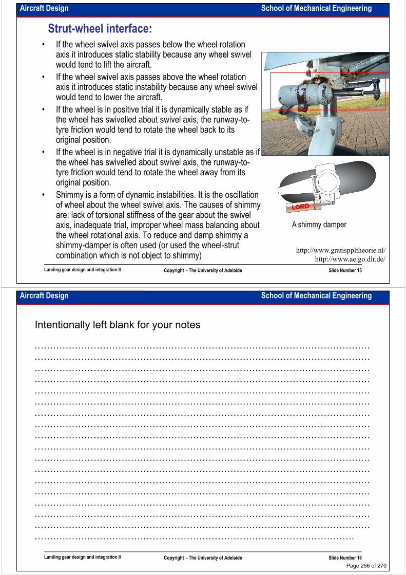
Aircraft Design School of Mechanical Engineering
Strut-wheel interface:
• If the wheel swivel axis passes below the wheel rotation axis it introduces static stability because any wheel swivel would tend to lift the aircraft.
• If the wheel swivel axis passes above the wheel rotation axis it introduces static instability because any wheel swivel would tend to lower the aircraft.would tend to lower the aircraft.
• If the wheel is in positive trial it is dynamically stable as if the wheel has swivelled about swivel axis, the runway-to-tyre friction would tend to rotate the wheel back to its original position.
• If the wheel is in negative trial it is dynamically unstable as if the wheel has swivelled about swivel axis, the runway-to-tyre friction would tend to rotate the wheel away from its original position.
• Shimmy is a form of dynamic instabilities. It is the oscillation
Landing gear design and integration II Copyright - The University of Adelaide Slide Number 15
• Shimmy is a form of dynamic instabilities. It is the oscillation of wheel about the wheel swivel axis. The causes of shimmy are: lack of torsional stiffness of the gear about the swivel axis, inadequate trial, improper wheel mass balancing about the wheel rotational axis. To reduce and damp shimmy a shimmy-damper is often used (or used the wheel-strut combination which is not object to shimmy) http://www.ae.go.dlr.de/
http://www.gratisppltheorie.nl/
A shimmy damper
Aircraft Design School of Mechanical Engineering
Intentionally left blank for your notes
………………………………………………………………………………………………
………………………………………………………………………………………………
………………………………………………………………………………………………
………………………………………………………………………………………………………………………………………………………………………………………………
………………………………………………………………………………………………
………………………………………………………………………………………………
………………………………………………………………………………………………
………………………………………………………………………………………………
………………………………………………………………………………………………
………………………………………………………………………………………………
………………………………………………………………………………………………
………………………………………………………………………………………………
………………………………………………………………………………………………
Landing gear design and integration II Copyright - The University of Adelaide Slide Number 16
………………………………………………………………………………………………
………………………………………………………………………………………………
………………………………………………………………………………………………
………………………………………………………………………………………………
………………………………………………………………………………………………
………………………………………………………………………………………….
Page 256 of 270

Aircraft Design School of Mechanical Engineering
Gear retraction geometry:
• Most low wing aircraft (civilian jet, fighters and GA) retract the gear into the wing-fuselage junction, in the wing or in the fuselage.
• Most mid and high wing • Most mid and high wing aircraft retract the gear into the fuselage. The drag penalty of this configuration can be substantial.
• Retraction of the gear into the nacelles behind the engine is typical for propeller driven aircraft.
• The wing-podded
Landing gear design and integration II Copyright - The University of Adelaide Slide Number 17
From Book: Aircraft design, a conceptual approach, by D. Raymer
Options for main landing gear retracted positions
• The wing-podded arrangement has minimum aerodynamic penalty as the pods placed at the trailing edge of the wing where some area-ruling benefit can be obtained.
Aircraft Design School of Mechanical Engineering
Gear retraction geometry:
Aft retracting gear Upward retracting gear Forward retracting gear
• The landing gear retraction mechanism can be very complicated (however most of them comprise of four-bar linkage).
• To retract a landing gear, hydraulic or electro-
Force-stroke
diagram
Landing gear design and integration II Copyright - The University of Adelaide Slide Number 18
From Book: Airplane design, by J. Roskam
• To retract a landing gear, hydraulic or electro-mechanical retraction actuators are used. The force-stroke diagram of the retraction actuator should not be peaky.
• A retraction mechanism normally is equipped with sensors, locks and micro switches
Page 257 of 270
Aircraft Design School of Mechanical Engineering
Seaplanes:• Using the seaplanes allows to increase
the wing loading (no limitation in takeoff distance), hence the aircraft has more efficiency in cruise range and speed.
• To reduce water spray, spray strips can be attached to the edge of the bottom.
Seaplane
geometries
be attached to the edge of the bottom.
• In the calculations it can be assumed that friction coefficient of a seaplane during takeoff and landing is about 0.10-0.15
• Flying boats are often equipped with beaching gears. Beaching gears help the aircraft to taxi up a ramp after landing on the water.
• In some cases flying boats are equipped with retractable landing gears. They can be operable on the ground and water
Float geometries
Landing gear design and integration II Copyright - The University of Adelaide Slide Number 19
be operable on the ground and water
• The other devices which facilitate an aircraft to land on the water are floats. The hydrodynamic performance of floats depends on their cross sectional shape.
• Air cushion landing system enhances the operational capability of an aircraft independent of runway surface. From Book: Aircraft design, a conceptual approach, by D. Raymer
From Book: Airplane design, by J. Roskam
Aircraft Design School of Mechanical Engineering
Intentionally left blank for your notes
………………………………………………………………………………………………
………………………………………………………………………………………………
………………………………………………………………………………………………
………………………………………………………………………………………………………………………………………………………………………………………………
………………………………………………………………………………………………
………………………………………………………………………………………………
………………………………………………………………………………………………
………………………………………………………………………………………………
………………………………………………………………………………………………
………………………………………………………………………………………………
………………………………………………………………………………………………
………………………………………………………………………………………………
………………………………………………………………………………………………
Landing gear design and integration II Copyright - The University of Adelaide Slide Number 20
………………………………………………………………………………………………
………………………………………………………………………………………………
………………………………………………………………………………………………
………………………………………………………………………………………………
………………………………………………………………………………………………
………………………………………………………………………………………….
Page 258 of 270
School of Mechanical EngineeringAircraft Design
Weight and balance analysis
Dr. MAZIAR ARJOMANDI
Semester I
Weight and balance analysis Copyright - The University of Adelaide Slide Number 1
Semester I
Aircraft Design School of Mechanical Engineering
Aircraft weight breakdown:• The following weight breakdown gives an
acceptable estimation of the aircraft weight:
1. Fuselage group
2. Wing group
3. Empennage group
∑∑∑===
===13
1
8
1
6
1
, , i
iTO
i
iOE
i
iE WWWWWW
• We also can write:
WE=Wstructure+Wpropulsion+Wsystem
Where:
Wstructure=Wfuselage+Wwing+Wempennage+Wlanding 3. Empennage group
4. Engine group
5. Landing gear group
6. Fixed equipment group
7. Trapped fuel and oil
8. Crew
9. Fuel
10. Passengers
11. Baggage
Wstructure=Wfuselage+Wwing+Wempennage+Wlanding gear
Or:
Statistical data show that:
gearempennagewingfuselagestructure WWWWW +++=
%4030
%4030
−=
−=fuselage
W
W
Weight and balance analysis Copyright - The University of Adelaide Slide Number 2
12. Cargo
13. Military load
• “Empty Weight” is the sum of the first 6 components, “Operational Weight Empty” is the sum of the first 8 components and “Takeoff Weight” is the sum of the all components.
For more detail statistics the following table can be used:
%1510
%105
%4030
−=
−=
−=
gear
empennage
wing
W
W
W
Page 259 of 270
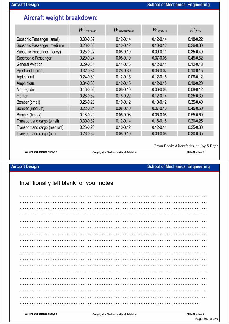
Aircraft Design School of Mechanical Engineering
Aircraft weight breakdown:
structureW propulsionW systemW fuelW
Subsonic Passenger (small) 0.30-0.32 0.12-0.14 0.12-0.14 0.18-0.22
Subsonic Passenger (medium) 0.28-0.30 0.10-0.12 0.10-0.12 0.26-0.30
Subsonic Passenger (heavy) 0.25-0.27 0.08-0.10 0.09-0.11 0.35-0.40
Supersonic Passenger 0.20-0.24 0.08-0.10 0.07-0.08 0.45-0.52
General Aviation 0.29-0.31 0.14-0.16 0.12-0.14 0.12-0.18
Sport and Trainer 0.32-0.34 0.26-0.30 0.06-0.07 0.10-0.15
Agricultural 0.24-0.30 0.12-0.15 0.12-0.15 0.08-0.12
Amphibious 0.34-0.38 0.12-0.15 0.12-0.15 0.10-0.20
Motor-glider 0.48-0.52 0.08-0.10 0.06-0.08 0.08-0.12
Fighter 0.28-0.32 0.18-0.22 0.12-0.14 0.25-0.30
Bomber (small) 0.26-0.28 0.10-0.12 0.10-0.12 0.35-0.40
Bomber (medium) 0.22-0.24 0.08-0.10 0.07-0.10 0.45-0.50
Weight and balance analysis Copyright - The University of Adelaide Slide Number 3
Bomber (medium) 0.22-0.24 0.08-0.10 0.07-0.10 0.45-0.50
Bomber (heavy) 0.18-0.20 0.06-0.08 0.06-0.08 0.55-0.60
Transport and cargo (small) 0.30-0.32 0.12-0.14 0.16-0.18 0.20-0.25
Transport and cargo (medium) 0.26-0.28 0.10-0.12 0.12-0.14 0.25-0.30
Transport and cargo (big) 0.28-0.32 0.08-0.10 0.06-0.08 0.30-0.35
From Book: Aircraft design, by S Eger
Aircraft Design School of Mechanical Engineering
Intentionally left blank for your notes
………………………………………………………………………………………………
………………………………………………………………………………………………
………………………………………………………………………………………………
………………………………………………………………………………………………………………………………………………………………………………………………
………………………………………………………………………………………………
………………………………………………………………………………………………
………………………………………………………………………………………………
………………………………………………………………………………………………
………………………………………………………………………………………………
………………………………………………………………………………………………
………………………………………………………………………………………………
………………………………………………………………………………………………
………………………………………………………………………………………………
Weight and balance analysis Copyright - The University of Adelaide Slide Number 4
………………………………………………………………………………………………
………………………………………………………………………………………………
………………………………………………………………………………………………
………………………………………………………………………………………………
………………………………………………………………………………………………
………………………………………………………………………………………….
Page 260 of 270
Aircraft Design School of Mechanical Engineering
Aircraft weight estimation:• To estimate the aircraft weight by using the statistical equations estimate the weight of various
components of the aircraft and then sum for the total empty weight.
• In detail design phase, the total weight of the aircraft is calculated by summing up the real weight of aircraft parts. Each design organisation has a special department responsible for weight and balance analysis of the aircraft. One of the challenging area for them is collecting the information about all aircraft parts which are used in manufacturing and their actual weights. (Usually the about all aircraft parts which are used in manufacturing and their actual weights. (Usually the weight of manufactured aircraft is more than the design weight of the aircraft!)
• There are different groups of equation for component weigh calculation in different references. Some of them give very accurate answer for a specific types of aircraft, while the others give a good estimation for all types of aircraft.
• This is of great importance to make all the decisions related to general layout of the aircraft e.g. braced or cantilever wing, pressurised or non-pressurised cabin, wing or fuselage mounted landing gear, wing or fuselage mounted engines and so on. These decisions have great influence on the result of component weigh estimation.
• Aircraft weight calculation is an iterative operation. If it is impossible to calculate the weight of a
Weight and balance analysis Copyright - The University of Adelaide Slide Number 5
• Aircraft weight calculation is an iterative operation. If it is impossible to calculate the weight of a few components due to lack of information, it is recommended to use the statistical data for finding their proportional weight and in the further stages estimate their weight more accurately.
• In the new and unusual types of aircraft (like UAVs, MAVs, amphibious aircraft, large transport, STOL/VTOL, spacecraft and …) due to lack of statistical data it is very hard to precisely estimate the weight of aircraft components. Hence it is required to increase the number of iteration and use the real weight of the component (use the detail design weight estimation data).
• For Weight estimation use Roskam’s (vol 5) or Raymer’s book
Aircraft Design School of Mechanical Engineering
Aircraft CG:• To find the CG position of total aircraft, CG
positions of major components should be found (as it was on the slide 2).
• Use the aircraft sketches estimate the CG position of the major structural components.
• CG position of fuel, passengers, crew and cargo
Location of CG’s of major components
• CG position of fuel, passengers, crew and cargo can be assumed at their geometrical centres
• Payload weight and its position and also fuel weight and fuel tanks arrangement have major influence on aircraft CG movement.
• Use the following equations to find aircraft CG position:
∑n
XW ∑n
YW ∑n
ZW
Weight and balance analysis Copyright - The University of Adelaide Slide Number 6
From Book: Airplane design, by J. Roskam
∑
∑
=
==n
i
i
i
ii
CG
W
XW
X
1
1
∑
∑
=
==n
i
i
i
ii
CG
W
YW
Y
1
1
∑
∑
=
==n
i
i
i
ii
CG
W
ZW
Z
1
1
Page 261 of 270
Aircraft Design School of Mechanical Engineering
CG envelope:• CG envelope can be plotted in terms
of fuselage station and also in terms
of a fraction of the MAC. (AS aircraft
AC usually is calculated in terms of
MAC, it is recommended to plot CG
envelope in terms of MAC.
Aircraft general
arrangement
CG envelope
envelope in terms of MAC.
• Most FWD and most AFT CG are two
main parameters for estimation of the
aircraft longitudinal stability
Weight and balance analysis Copyright - The University of Adelaide Slide Number 7
From Book: Airplane design, by J. Roskam
Aircraft Design School of Mechanical Engineering
Intentionally left blank for your notes
………………………………………………………………………………………………
………………………………………………………………………………………………
………………………………………………………………………………………………
………………………………………………………………………………………………………………………………………………………………………………………………
………………………………………………………………………………………………
………………………………………………………………………………………………
………………………………………………………………………………………………
………………………………………………………………………………………………
………………………………………………………………………………………………
………………………………………………………………………………………………
………………………………………………………………………………………………
………………………………………………………………………………………………
………………………………………………………………………………………………
Weight and balance analysis Copyright - The University of Adelaide Slide Number 8
………………………………………………………………………………………………
………………………………………………………………………………………………
………………………………………………………………………………………………
………………………………………………………………………………………………
………………………………………………………………………………………………
………………………………………………………………………………………….
Page 262 of 270
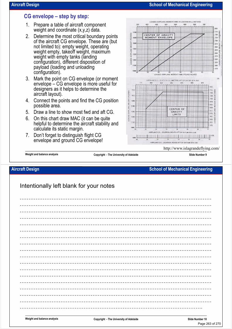
Aircraft Design School of Mechanical Engineering
CG envelope – step by step:
1. Prepare a table of aircraft component weight and coordinate (x,y,z) data.
2. Determine the most critical boundary points of the aircraft CG envelope. These are (but not limited to): empty weight, operating weight empty, takeoff weight, maximum weight with empty tanks (landing weight with empty tanks (landing configuration), different disposition of payload (loading and unloading configuration).
3. Mark the point on CG envelope (or moment envelope – CG envelope is more useful for designers as it helps to determine the aircraft layout).
4. Connect the points and find the CG position possible area.
Weight and balance analysis Copyright - The University of Adelaide Slide Number 9
5. Draw a line to show most fwd and aft CG.
6. On this chart draw MAC (it can be quite helpful to determine the aircraft stability and calculate its static margin.
7. Don’t forget to distinguish flight CG envelope and ground CG envelope!
http://www.islagrandeflying.com/
Aircraft Design School of Mechanical Engineering
Intentionally left blank for your notes
………………………………………………………………………………………………
………………………………………………………………………………………………
………………………………………………………………………………………………
………………………………………………………………………………………………………………………………………………………………………………………………
………………………………………………………………………………………………
………………………………………………………………………………………………
………………………………………………………………………………………………
………………………………………………………………………………………………
………………………………………………………………………………………………
………………………………………………………………………………………………
………………………………………………………………………………………………
………………………………………………………………………………………………
………………………………………………………………………………………………
Weight and balance analysis Copyright - The University of Adelaide Slide Number 10
………………………………………………………………………………………………
………………………………………………………………………………………………
………………………………………………………………………………………………
………………………………………………………………………………………………
………………………………………………………………………………………………
………………………………………………………………………………………….
Page 263 of 270
School of Mechanical EngineeringAircraft Design
Stability and control analysis
Dr. MAZIAR ARJOMANDI
Semester I
Stability and control analysis Copyright - The University of Adelaide Slide Number 1
Semester I
Aircraft Design School of Mechanical Engineering
Main rules:• Airplane must be controllable, manoeuvrable and trimmable to be safe and useful.
– Longitudinal controllability and trim
– Directional and lateral controllability and trim
– Minimum control speed
– Manoeuvring flight
– Control during takeoff and landing
– High speed characteristics
• Aircraft must fly stably (it can be unstable but must fly stably).
– Static longitudinal, lateral and directional stability
– Dynamic longitudinal, lateral and directional stability
– Stall characteristics
– Spin
– Aeroelastic considerations
Stability and control analysis Copyright - The University of Adelaide Slide Number 2
– Aeroelastic considerations
• Aircraft must possess ride quality such that the crew can carry out its functions.
In this course we present a rapid method for stability and
controllability analysis of the designed aircraft
Page 264 of 270

Aircraft Design School of Mechanical Engineering
Longitudinal X-plot• Longitudinal X-plot gives a good
understanding of compatibility between aircraft static margin and horizontal tail (or canard) area.
• CG moves aft with increasing the horizontal tail area (in canard CG moves fwd).
• AC moves aft with increasing the horizontal tail area with the higher rate than CG (in canard AC moves fwd).
• Desired static margin (distance between AC and CG) can be found on the graph.
• Pay attention that for horizontal tail sizing in conventional configuration (canard sizing in canard configuration), static margin is calculated as the distance between most aft CG and AC (the smallest static margin).
Longitudinal X-plot
Stability and control analysis Copyright - The University of Adelaide Slide Number 3
aft CG and AC (the smallest static margin).
• As it was stated before it is recommended to calculate AC and CG as the fractions of MAC
• In some books X-plot is called stability scissors.
• Recall: From Book: Airplane design, by J. Roskam
ACCG
L
m
L
m XXC
C
dC
dC−==
α
α
Aircraft Design School of Mechanical Engineering
Intentionally left blank for your notes
………………………………………………………………………………………………
………………………………………………………………………………………………
………………………………………………………………………………………………
………………………………………………………………………………………………………………………………………………………………………………………………
………………………………………………………………………………………………
………………………………………………………………………………………………
………………………………………………………………………………………………
………………………………………………………………………………………………
………………………………………………………………………………………………
………………………………………………………………………………………………
………………………………………………………………………………………………
………………………………………………………………………………………………
………………………………………………………………………………………………
Stability and control analysis Copyright - The University of Adelaide Slide Number 4
………………………………………………………………………………………………
………………………………………………………………………………………………
………………………………………………………………………………………………
………………………………………………………………………………………………
………………………………………………………………………………………………
………………………………………………………………………………………….
Page 265 of 270
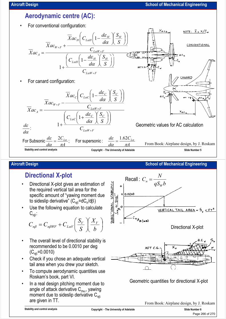
Aircraft Design School of Mechanical Engineering
Aerodynamic centre (AC):
FWL
HHHLH
FW
A
C
S
S
d
dCacX
acX
acX ++
−
+= α
α
ε
αε
1
• For conventional configuration:
FWL
HHHL
A
C
S
S
d
dC
acX
+
−
+
=
α
α αε
1
1
CCCLC
FWC
S
S
d
dCacX
acX +
−−
α αε
1
• For canard configuration:
Stability and control analysis Copyright - The University of Adelaide Slide Number 5
From Book: Airplane design, by J. Roskam
Geometric values for AC calculationFWL
CCCL
FWL
FW
A
C
S
S
d
dC
CacX
+
++
++
=
α
α
α
αε
1
1
A
C
d
d
A
C
d
d
d
d
LL
παε
παε
αε
αα 62.12== :supersonic For ;Subsonic For
:
Aircraft Design School of Mechanical Engineering
Directional X-plot
• Directional X-plot gives an estimation of the required vertical tail area for the specific amount of “yawing moment due to sideslip derivative” (Cnβ=dCn/dβ)
• Use the following equation to calculate Cnβ:
bqS
NC
W
n = :Recall
Cnβ:
• The overall level of directional stability is recommended to be 0.0010 per deg (Cnβ=0.0010)
• Check if you chose an adequate vertical tail area when you drew your sketch.
Directional X-plot
+=b
X
S
SCCC VV
VLWFnn αββ
Stability and control analysis Copyright - The University of Adelaide Slide Number 6
tail area when you drew your sketch.
• To compute aerodynamic quantities use Roskam’s book, part VI.
• In a real design pitching moment due to angle of attack derivative Cmα, yawing moment due to sideslip derivative Cnβare given in TT.
From Book: Airplane design, by J. Roskam
Geometric quantities for directional X-plot
Page 266 of 270
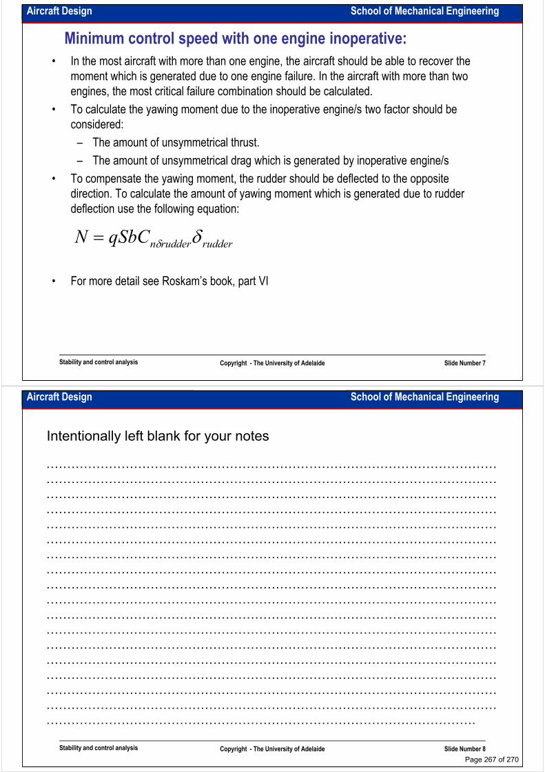
Aircraft Design School of Mechanical Engineering
Minimum control speed with one engine inoperative:
• In the most aircraft with more than one engine, the aircraft should be able to recover the
moment which is generated due to one engine failure. In the aircraft with more than two
engines, the most critical failure combination should be calculated.
• To calculate the yawing moment due to the inoperative engine/s two factor should be
considered:considered:
– The amount of unsymmetrical thrust.
– The amount of unsymmetrical drag which is generated by inoperative engine/s
• To compensate the yawing moment, the rudder should be deflected to the opposite
direction. To calculate the amount of yawing moment which is generated due to rudder
deflection use the following equation:
rudderruddernqSbCN δδ=
Stability and control analysis Copyright - The University of Adelaide Slide Number 7
• For more detail see Roskam’s book, part VI
Aircraft Design School of Mechanical Engineering
Intentionally left blank for your notes
………………………………………………………………………………………………
………………………………………………………………………………………………
………………………………………………………………………………………………
………………………………………………………………………………………………………………………………………………………………………………………………
………………………………………………………………………………………………
………………………………………………………………………………………………
………………………………………………………………………………………………
………………………………………………………………………………………………
………………………………………………………………………………………………
………………………………………………………………………………………………
………………………………………………………………………………………………
………………………………………………………………………………………………
………………………………………………………………………………………………
Stability and control analysis Copyright - The University of Adelaide Slide Number 8
………………………………………………………………………………………………
………………………………………………………………………………………………
………………………………………………………………………………………………
………………………………………………………………………………………………
………………………………………………………………………………………………
………………………………………………………………………………………….
Page 267 of 270
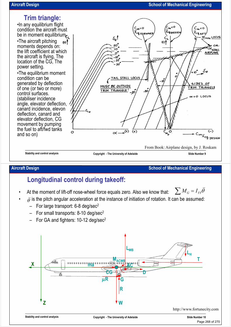
Aircraft Design School of Mechanical Engineering
Trim triangle:•In any equilibrium flight condition the aircraft must be in moment equilibrium.
•The aircraft pitching moments depends on: the lift coefficient at which the aircraft is flying, The the aircraft is flying, The location of the CG, The power setting.
•The equilibrium moment condition can be generated by deflection of one (or two or more) control surfaces. (stabiliser incidence angle, elevator deflection, canard incidence, elevon
Stability and control analysis Copyright - The University of Adelaide Slide Number 9
From Book: Airplane design, by J. Roskam
canard incidence, elevon deflection, canard and elevator deflection, CG movement by pumping the fuel to aft/fwd tanks and so on)
Aircraft Design School of Mechanical Engineering
Longitudinal control during takeoff:
• At the moment of lift-off nose-wheel force equals zero. Also we know that:
• is the pitch angular acceleration at the instance of initiation of rotation. It can be assumed:
– For large transport: 6-8 deg/sec2
– For small transports: 8-10 deg/sec2
– For GA and fighters: 10-12 deg/sec2
∑ = θɺɺYYG IM
θɺɺ
– For GA and fighters: 10-12 deg/sec2
X
CG
maT
LH
LWB
AC
D
MACWB
Stability and control analysis Copyright - The University of Adelaide Slide Number 10
http://www.fortunecity.com
Z W
CG
G
R
µµµµR
D
Page 268 of 270
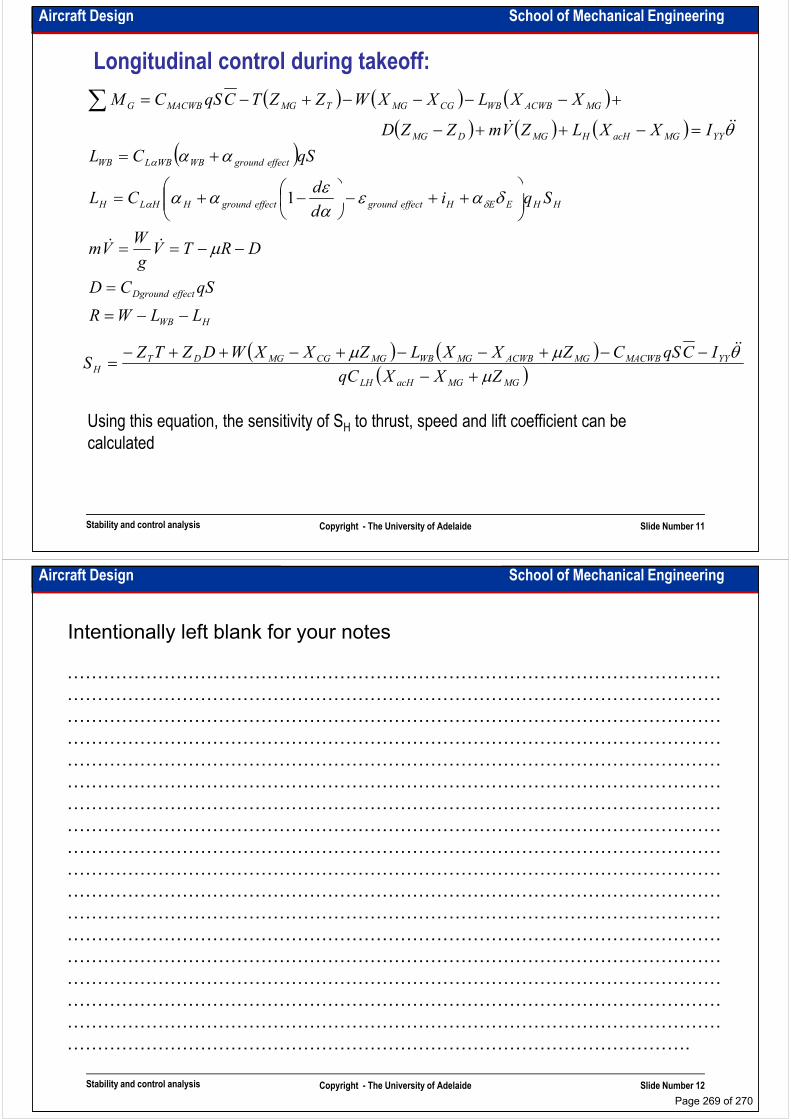
Aircraft Design School of Mechanical Engineering
Longitudinal control during takeoff:
( ) ( ) ( )( ) ( ) ( )
( )effectgroundWBWBLWB
YYMGacHHMGDMG
MGACWBWBCGMGTMGMACWBG
Sqid
CL
qSCL
IXXLZVmZZD
XXLXXWZZTCqSCM
++−
−+=
+=
=−++−
+−−−−+−=∑
δαεε
αα
αα
θ
α
ɺɺɺ
1
HWB
effectDground
HHEEHeffectgroundeffectgroundHHLH
LLWR
qSCD
DRTVg
WVm
Sqid
dCL
−−=
=
−−==
++−
−+=
µ
δαεαε
αα δα
ɺɺ
1
( ) ( )( )
YYMACWBMGACWBMGWBMGCGMGDTH
ZXXqC
ICqSCZXXLZXXWDZTZS
µθµµ
+−−−+−−+−++−
=ɺɺ
Stability and control analysis Copyright - The University of Adelaide Slide Number 11
( )MGMGacHLH
HZXXqC
Sµ+−
=
Using this equation, the sensitivity of SH to thrust, speed and lift coefficient can be
calculated
Aircraft Design School of Mechanical Engineering
Intentionally left blank for your notes
………………………………………………………………………………………………
………………………………………………………………………………………………
………………………………………………………………………………………………
………………………………………………………………………………………………………………………………………………………………………………………………
………………………………………………………………………………………………
………………………………………………………………………………………………
………………………………………………………………………………………………
………………………………………………………………………………………………
………………………………………………………………………………………………
………………………………………………………………………………………………
………………………………………………………………………………………………
………………………………………………………………………………………………
………………………………………………………………………………………………
Stability and control analysis Copyright - The University of Adelaide Slide Number 12
………………………………………………………………………………………………
………………………………………………………………………………………………
………………………………………………………………………………………………
………………………………………………………………………………………………
………………………………………………………………………………………………
………………………………………………………………………………………….
Page 269 of 270

Aircraft Design School of Mechanical Engineering
Introduction to dynamic stability:
• To study dynamic stability two classes of force must be considered: the inertia forces and the damping forces:
• Inertia forces drive from the tendency of mass to resist acceleration. A body’s resistance to rotational acceleration is described by mass moment of inertia. To calculate aircraft mass moment of inertia (IXX, IYY, IZZ) we can use components weight table (the methods for estimation of mass moment of inertia are presented in Roskam’s table (the methods for estimation of mass moment of inertia are presented in Roskam’s and Raymer’s books.
• The rotational damping forces, which are proportional to the pitch, roll and yaw rates, are generated because of a change in effective angle of attack due to rotational motion. The change in effective angle of attack, and hence the change in lift, is directly proportional to the rotation rate and the distance from the CG
• The 6DOF analysis allows simultaneous rotations in pitch, yaw and roll, and allows the aircraft velocity to change in the vertical, lateral and longitudinal directions. The 1DOF equations can be used for initial assessment of simple flight conditions
Stability and control analysis Copyright - The University of Adelaide Slide Number 13
equations can be used for initial assessment of simple flight conditions
PbCqSbCqSPI
RbCqSbCqSRI
QcCqScCqSQI
lPWlWXX
nRWnWZZ
mQWmWYY
+=
+=
+=
ɺ
ɺ
ɺ
:Roll
:Yaw
:Pitch
β
α
β
α
Aircraft Design School of Mechanical Engineering
Intentionally left blank for your notes
………………………………………………………………………………………………
………………………………………………………………………………………………
………………………………………………………………………………………………
………………………………………………………………………………………………………………………………………………………………………………………………
………………………………………………………………………………………………
………………………………………………………………………………………………
………………………………………………………………………………………………
………………………………………………………………………………………………
………………………………………………………………………………………………
………………………………………………………………………………………………
………………………………………………………………………………………………
………………………………………………………………………………………………
………………………………………………………………………………………………
Stability and control analysis Copyright - The University of Adelaide Slide Number 14
………………………………………………………………………………………………
………………………………………………………………………………………………
………………………………………………………………………………………………
………………………………………………………………………………………………
………………………………………………………………………………………………
………………………………………………………………………………………….
Page 270 of 270