aircraft recovery manual - bombardier inc....24 oct 31/2014 20141031 25 dec 22/2015 20151222 26 oct...
TRANSCRIPT
AircraftRecoveryManual
Publication No. CH 300 ARM
MODEL
BD-100-1A10 (CH-300)
A/C EFFECTIVITY
20003-20457
BD-100-1A10 (CH-350) 20501-20999

BOMBARDIER CHALLENGER* 300 and 350 (MODEL BD-100-1A10)
AIRCRAFT RECOVERY MANUAL
Bombardier AerospaceP. O. Box 6087, Station Centre-villeMontreal, Quebec, Canada H3C 3G9
http://www.cic.bombardier.com
For more information regarding Technical Publications please contact:
Bombardier Customer Services Business Aircraft
Customer Services Hotline (Technical Assistance & In-flight Emergencies)North America: 1-866-JET-1247 (1-866-538-1247) [Press 1]International: +1-514-855-2999 [Press 1]Email: [email protected]
User Comments (Technical Publications)North America: 1-866-JET-1247 (1-866-538-1247) [Press 4 then option 2]International: +1-514-855-2999 [Press 4 then option 2]Email: [email protected]
Ordering & Distribution (Technical Publications)North America: 1-866-JET-1247 (1-866-538-1247) [Press 4 then option 1]International: +1-514-855-2999 [Press 4 then option 1]Facsimile: 514-855-2770Email: [email protected]
To ease the ordering process, the following DocumentIdentification Number should be used: CH 300 ARM
It is understood that this documentation, comprising technical data and other information in any media shall not be reproduced or disclosed in whole or in part without Bombardier's written authorization, is proprietary and confidential to Bombardier and that all rights to patent, copyright, trademark, trade secret and other intellectual property rights therein belong to Bombardier. Such documentation, technical data and other information shall not be modified, translated, reverse assembled, reverse engineered or de-compiled and shall be used solely to maintain, operate or repair the aircraft.
Copyright © 2013 by Bombardier Inc. All rights reserved.*Trademark of Bombardier Inc. or its subsidiaries.Printed in Canada
the evolution of mobility

USER COMMENTSON ERRORS, OMISSIONS, PROCEDURES (IF APPLICABLE), ETC.
To: Bombardier Business Aircraft, Customer SupportDepartment 631 (Technical Publications and Information)
From: Date:
Address:
E−mail: Aircraft S/N:
Telephone No. (please print)
The following publication requires correction or clarification:
Publication: Page Date:
Chap./Sect. No. Page No. Para No. Fig. No.
Comments:
You can send your user comment as follows:
− by telephone at (514) 855−9304
− by e−mail to [email protected]
− by fax at (514) 855−7894
− by mailing it to the address on the back of this page.

Bombardier Business Aircraft, Customer SupportP.O. Box 6087, Station Centre−villeMontreal, Quebec, Canada H3C 3G9
Attn: User Comments CoordinatorDepartment 631

USER COMMENTSON ERRORS, OMISSIONS, PROCEDURES (IF APPLICABLE), ETC.
To: Bombardier Business Aircraft, Customer SupportDepartment 631 (Technical Publications and Information)
From: Date:
Address:
E−mail: Aircraft S/N:
Telephone No. (please print)
The following publication requires correction or clarification:
Publication: Page Date:
Chap./Sect. No. Page No. Para No. Fig. No.
Comments:
You can send your user comment as follows:
− by telephone at (514) 855−9304
− by e−mail to [email protected]
− by fax at (514) 855−7894
− by mailing it to the address on the back of this page.

Bombardier Business Aircraft, Customer SupportP.O. Box 6087, Station Centre−villeMontreal, Quebec, Canada H3C 3G9
Attn: User Comments CoordinatorDepartment 631

1 Jul 11/2005 Jul 11/2005 Bombardier
2 Oct 25/2007 Oct 25/2007 Bombardier
3 Jan 30/2012 Jan 30/2012 Bombardier
4 Oct 05/2012 Oct 05/2012 Bombardier
5 Jan 31/2013 Jan 31/2013 Bombardier
6 Jan 29/2014 Jan 29/2014 Bombardier
7 May 08/2014 May 08/2014 Bombardier
8 Oct 31/2014 Oct 31/2014 Bombardier
9 Dec 22/2015 Dec 22/2015 Bombardier
BD−100 AIRCRAFT RECOVERY MANUAL
RECORD OF REVISIONS
A signature in the "INSERTED BY" column shows thatthe publication holder has incorporated the revision.
REVISION NO. ISSUE DATE DATE INSERTED INSERTED BY


BD−100 AIRCRAFT RECOVERY MANUAL
RECORD OF TEMPORARY REVISIONS
TEMPORARYREV. NO.
SECTION AND PAGENO.
ISSUEDATE
DATEINSERTED
INSERTEDBY
DATEREMOVED
REMOVEDBY


Effective Pages 1 Dec 22/2015 20151222
2 Dec 22/2015 20151222
Contents 1 Jan 29/2014 20140129
2 Oct 31/2014 20141031
Section 01 1 Jan 29/2014 20140129
2 Jan 29/2014 20140129
3 Jan 29/2014 20140129
Section 02 1 Jul 11/2005 20050711
2 Oct 25/2007 20071025
3 Oct 25/2007 20071025
4 Jan 29/2014 20140129
5 Jan 29/2014 20140129
6 Oct 25/2007 20071025
7 Jan 29/2014 20140129
8 Jan 29/2014 20140129
9 Jan 29/2014 20140129
10 Jan 29/2014 20140129
11 Jan 29/2014 20140129
12 Jan 29/2014 20140129
13 Jan 29/2014 20140129
14 Jan 29/2014 20140129
15 Jan 29/2014 20140129
16 Jan 29/2014 20140129
17 Jan 29/2014 20140129
18 Jan 29/2014 20140129
19 Jan 29/2014 20140129
20 Jan 29/2014 20140129
21 Jan 29/2014 20140129
22 Jan 29/2014 20140129
23 Jan 29/2014 20140129
Section 03 1 Oct 31/2014 20141031
2 Jan 29/2014 20140129
3 Oct 31/2014 20141031
4 Oct 31/2014 20141031
5 Oct 31/2014 20141031
6 Oct 31/2014 20141031
7 Oct 31/2014 20141031
8 Oct 31/2014 20141031
9 Oct 31/2014 20141031
Section 04 1 Jan 30/2012 20120130
2 Jul 11/2005 20050711
3 Jul 11/2005 20050711
4 Jul 11/2005 20050711
5 Jul 11/2005 20050711
6 Jul 11/2005 20050711
7 Jul 11/2005 20050711
8 Jul 11/2005 20050711
9 Jul 11/2005 20050711
10 Jul 11/2005 20050711
11 Jul 11/2005 20050711
12 Jul 11/2005 20050711
Section 05 1 Jan 31/2013 20130131
2 Jul 11/2005 20050711
3 Jul 11/2005 20050711
4 Jul 11/2005 20050711
5 Jul 11/2005 20050711
6 Jul 11/2005 20050711
7 Oct 31/2014 20141031
8 Jul 11/2005 20050711
9 Oct 31/2014 20141031
10 Oct 31/2014 20141031
11 Oct 31/2014 20141031
12 Oct 31/2014 20141031
13 Oct 31/2014 20141031
14 Oct 31/2014 20141031
15 Oct 31/2014 20141031
16 Oct 31/2014 20141031
17 Oct 31/2014 20141031
18 Oct 31/2014 20141031
19 Oct 31/2014 20141031
20 Oct 31/2014 20141031
21 Oct 31/2014 20141031
22 Oct 31/2014 20141031
23 Oct 31/2014 20141031
24 Oct 31/2014 20141031
25 Dec 22/2015 20151222
26 Oct 31/2014 20141031
27 Dec 22/2015 20151222
28 Oct 31/2014 20141031
29 Oct 31/2014 20141031
BD−100 AIRCRAFT RECOVERY MANUAL
BD−100 AIRCRAFT RECOVERY MANUAL
LIST OF EFFECTIVE PAGES
Page 1Dec 22/2015
Title Effectivity Page Date Title Effectivity Page Date
EFFECTIVITY: ALL
EFFECTIVE PAGES

Section 06 1 Oct 31/2014 20141031
2 Oct 31/2014 20141031
3 Jul 11/2005 20050711
4 Oct 31/2014 20141031
5 Oct 31/2014 20141031
6 Oct 31/2014 20141031
7 Oct 31/2014 20141031
8 Oct 31/2014 20141031
9 Oct 31/2014 20141031
10 Oct 31/2014 20141031
BD−100 AIRCRAFT RECOVERY MANUAL
Page 2Dec 22/2015
Title Effectivity Page Date Title Effectivity Page Date
EFFECTIVITY: ALL
EFFECTIVE PAGES

SECTION 01 − IntroductionScope of the Manual 1Manual OrganizationCorrespondence 2Statement of LiabilityTechnical GlossaryDimensions 3
SECTION 02 − Aircraft RecoveryQuick Reference Guide 1Planning for Aircraft Recovery 3
GeneralAircraft Recovery Plan
Moving the Aircraft 5GeneralSteps and Recommendations for an Efficient Aircraft Recovery 6
Terrain Consideration 21GeneralFactors to Find the Most Practical Recovery PlanGround Conditions
SECTION 03 − Aircraft − GeneralModel Designation and Type 1Aircraft DimensionsDangerous AreasDoorsComposite MaterialsInterior Configurations 2
SECTION 04 − Emergency InformationEmergency Access 1
Passenger DoorOverwing Emergency−Exit Door 3Baggage Door 5Aft Equipment−Compartment Door 7Service Doors and Panels 9Windshields and Windows 11
BD−100 AIRCRAFT RECOVERY MANUAL
BD−100 AIRCRAFT RECOVERY MANUAL
TABLE OF CONTENTS
Page 1Jan 29/2014
Section Page
EFFECTIVITY: ALL
CONTENTS

SECTION 05 − Fire FightingGeneral 1On−Board Fire−Fighting Equipment 4Engine/APU Fire Controls 7Electrical Control Panels and Battery Locations 16Flammable Fluids and Gases 19Fuel System General Layout 21Emergency Break−In Zone 25TiresComposite Material Fire Precautions
GeneralDangerous Effects of Free FibersControl of Free Fibers 26
SECTION 06 − Ground SafetyTowing the Aircraft 1
GeneralTowing the Aircraft with BridleGround Lockpins 2Safety Precautions 9
BD−100 AIRCRAFT RECOVERY MANUAL
Page 2Oct 31/2014
Section Page
EFFECTIVITY: ALL
CONTENTS

INTRODUCTION
1. Scope of the Manual
A. Bombardier Business Aircraft Customer Support (BBACS) prepared the AircraftRecovery Manual to help an Airport Authority, an FBO, and/or an aircraft recovery crew ifan accident occurs with a Bombardier Challenger BD−100−1A10 model Business Jet.Because there are many Completion Centers that do different passenger compartmentlayout, it is not possible to give all the different layouts in this manual.
B. Challenger BD−100−1A10 model referred in this manual, include:
− Challenger 300
− Challenger 350
C. No aircraft recovery operation will be the same as other recovery operations because of:
− The accident or the incident itself,
− The location of the aircraft,
− The amount of aid that is available locally,
− The weather conditions when the accident/incident occurred. Also, the effects of theweather before and during the recovery operation,
− The number of persons that are available to help with the recovery.
2. Manual Organization
A. There are six sections in this manual:
− Section 1 − INTRODUCTION
− Section 2 − AIRCRAFT RECOVERY
− Section 3 − AIRCRAFT − GENERAL
− Section 4 − EMERGENCY INFORMATION
− Section 5 − FIRE FIGHTING
− Section 6 − GROUND SAFETY
BD−100 AIRCRAFT RECOVERY MANUAL
EFFECTIVITY: ALL
SECTION 01 Page 1Jan 29/2014

3. Correspondence
A. Send your questions and suggestions to:
By e−mail to: [email protected] (preferred) orBy phone at: Customer Response Center (CRC)Local and International: 514−855−2999North America only: 1−866−JET−1247 (1−866−538−1247) Tool FreeAttention: Air Safety Investigation, Department 686−5
4. Statement of Liability
A. This manual is intended to be used by Aircraft Crash Recovery crews involved in therecovery of any Bombardier BD−100−1A10 Challenger model Business Jet whichbecomes involved in an accident or incident. It is also intended to help those personsplanning for the unlikely event that will require recovery actions. The actions described inthis manual are intended as recommendations only, as to how aircraft recovery tasksshould be carried out. Any omission of a task or an action, or any omission to a task oraction, shall not be interpreted as an admission of liability by Bombardier Inc., or any ofits sub−groups of affiliates or related entities.
5. Technical Glossary
A. Refer to Table 1 for a Technical Glossary of aircraft terminology and abbreviations.
Table 1− Technical Glossary
A/C Aircraft
ac Alternating Current
AFFF Aqueous Fire Fighting Foam
APU Auxiliary Power Unit
AUX Auxiliary
CBR California Bearing Ratio
dc Direct Current
DISCH Discharge
ELECT PWR Electrical Power
ENG Engine
BD−100 AIRCRAFT RECOVERY MANUAL
EFFECTIVITY: ALL
SECTION 01 Page 2Jan 29/2014

Table 1− Technical Glossary
EQP Equipment Bay
FBO Fixed Base Operator
FS Fuselage Station
FT/SEC Feet per second
IATP International Air Technical Pool
ICAO International Civil Aviation Organization
IIC Investigator−in−Charge
KM/H Kilometers per hour
LWR FUS Lower Fuselage
mm Millimeter
mph miles per hour
MLG Main Landing Gear
NLG Nose Landing Gear
T/E Trailing Edge
TYP Typical
6. Dimensions
A. Linear dimensions given in this manual are in inches. The metric equivalents are given inparentheses ( ).
BD−100 AIRCRAFT RECOVERY MANUAL
EFFECTIVITY: ALL
SECTION 01 Page 3Jan 29/2014


AIRCRAFT RECOVERY
1. Quick Reference Guide
A. The leader of the recovery operation can use the Quick Reference Guide that follows asa checklist for the recovery team to refer to.
(1) Do the weight and balance
(a) Find the weight and balance of the aircraft to make an estimate of the limits tojack and tow the aircraft.
(b) Record the quantity and location of cargo and fuel to calculate the weight andbalance.
NOTE: You may have to calculate the weight and balance more than onetime during the recovery operations.
(2) Get initial data about the incident
(a) Set up interfaces with the Investigator−in−Charge (IIC), local authorities, theaircraft manufacturer’s (Bombardier) representative, and the owner’s agent orrepresentative.
(b) Tell the recovery crew surveyor to make a full estimate of the site as quickly aspossible. The type of accident site can have an effect on the aircraft removal.
(c) Make a note of the slope of the terrain, the ground cover (e.g. trees, grass,rock), and the distance from the runways, taxiways, and aprons.
(d) Make an analysis of the ground condition to calculate the bearing areanecessary to lift and move the aircraft.
(e) Choose suitable personnel (as well as the recovery crew members) and makean estimate of the necessary equipment, and related manuals.
(f) Get accommodations, transportation, work visas (when necessary), andmoney for the recovery team.
NOTE: The IIC must be at the site before this occurs.
(g) At the site, speak to local airport authorities, regulatory authorities, andnational investigating authorities.
BD−100 AIRCRAFT RECOVERY MANUAL
EFFECTIVITY: ALL
SECTION 02 Page 1Jul 11/2005

Get data on the items that follow:
− Local environment
− Climate
− Terrain structure
− Communications
− Local regulations for the defueling of the aircraft.
(3) Set Up Interfaces
(a) Make a detailed aircraft recovery plan (use a general recovery plan).
(b) Get permission from local and national authorities to continue with therecovery operation. It is necessary for the different authorities to find thecause(s) of an aircraft accident. You must know and follow the regulatoryauthority regulations, and the laws of the country in which the accident occurs.
(c) Move personnel and equipment to the recovery site.
(d) Prepare hangar and/or parking space for the aircraft. Refer to section 3 figure1 for aircraft dimensions.
(e) Make sure that cranes are locally available. Also, make sure that other heavyequipment, building materials and access roads are available. Some operatorsare member of an organization that share their technical facilities, services andrecovery equipment (recovery kits). The International Air Technical Pool (IATP)is the organization that manages the recovery pool arrangement.
(f) If components are removed from the aircraft for recovery purposes, the centerof gravity weight and balance location must be re−calculated before the aircraftis moved.
(g) If possible, remove all health risk payload (fuel, oils, dangerous materials,catering, oxygen, squibs, galley and lavatory disposal and water) from theaircraft.
NOTE: Follow the applicable local regulations concerning defueling.
(h) If possible, remove the baggage, cargo and flyaway kit.
(i) If required, remove primary components as necessary.
(j) Refer to Section 6 − GROUND SAFETY for data on the installation of theground lockpins. These lockpins are used, where possible, to safety thelanding gear for operations on the ground.
(k) Prepare to tether, lift and move the aircraft.
BD−100 AIRCRAFT RECOVERY MANUAL
EFFECTIVITY: ALL
SECTION 02 Page 2Oct 25/2007

(l) Complete the aircraft damage report when the aircraft recovery is completed.The damage report is made by the Bombardier investigating team, or aTechnical Support/Engineering team that is specially assembled for the task.
2. Planning for Aircraft Recovery
A. General
CAUTION: THE SPECIAL PROBLEMS THAT ARE RELATED TO AN AIRCRAFTRECOVERY OPERATION MAKE IT NECESSARY FOR ONE APPROVEDPERSON TO DIRECT ALL OF THE OPERATION.
(1) Refer to the International Civil Aviation Organization (ICAO) documentNo. 9137−AN/898, Airport Services Manual; Part 5, "Removal Of Disabled Aircraft"as an aid for aircraft recovery.
(2) The document gives the procedures to use for the recovery and/or the removal of adisabled aircraft. Some advanced procedures that are necessary are as follows:
(a) When you have to move an aircraft that cannot taxi or be towed with anapproved towbar or towing bridle, use other recovery procedures. The aircraftmay be lifted with pneumatic bags or cranes and move on a trailer or dollies.
(b) Advance planning is important to make sure that the equipment and personswith the skills to do a recovery operation are available when necessary.
(c) Prepare a full "Aircraft Recovery Plan" which may be started as soon as anaccident occurs and at the request of the IIC.
(d) Make sure to have the necessary emergency procedures. Give to theapplicable personnel, the tasks they are responsible for.
(e) Tell all major users of the airport about the airport management policies thatapply to the removal of disabled aircraft. Include applicable parts of thisdocument in the airport procedure.
NOTE: We recommend that a copy of this document be in the airport’s"Aircraft Recovery Plan."
B. Aircraft Recovery Plan
(1) The Aircraft Recovery Plan includes:
(a) Guidelines for the fast removal of a disabled aircraft from airport operationalareas as well as the time necessary to prevent secondary damage to theaircraft.
BD−100 AIRCRAFT RECOVERY MANUAL
EFFECTIVITY: ALL
SECTION 02 Page 3Oct 25/2007

(b) Detailed grid maps for use during aircraft recovery operations. The maps mustshow the topography of the airport site, approaches and adjacent areas. Theymust also show roads, ditches, gates, ground conditions and other factors thatcould have an effect on the aircraft recovery operations.
(c) Details about access roads to all parts of the airport that are near overheadpower lines or bridges, specially those roads necessary for heavy equipmentsuch as cranes.
(d) Bombardier’s data on the Challenger Series aircraft that uses the airport. Foraircraft recovery, the important data is the weight and balance, lifting andmoving, and weight reduction numbers.
(e) The type and location of heavy or special equipment and the time necessaryfor the equipment to get to the airport. Equipment to defuel aircraft must beavailable to move to all areas or locations. Because of the dimensions of theChallenger Series aircraft, cranes and slings can be used to lift the aircraft.Because of this, you can include the availability of cranes in the recovery plan.
NOTE: If not available, try to get aircraft recovery kits from other airports asquickly as possible.
The ICAO "Airport Services Manual", Part 5, gives a worldwide list ofaircraft recovery kits.
(f) Sources of personnel with different skills, ranging from laborers to aircraftmechanics.
(g) The requirement for food, clothes, and shelter for the recovery crew.
(h) Flexible procedures for communications, security and safety for the recoveryoperations, that are correct for the site.
(i) An active inventory of local salvage equipment that is available to the airport.The operator can get aircraft removal equipment and crews through contractswith airport owners, military airfields or aeronautical industries near the airport.
(j) Airport rules must make sure of the items that follow:
1 The airport owner’s right to close all or part of the airport as necessary.
2 The limits of liability and penalties for violations.
NOTE: An agreement must received from the IIC or the senior official ofthe investigation team, before the airport owner can move adisabled aircraft.
BD−100 AIRCRAFT RECOVERY MANUAL
EFFECTIVITY: ALL
SECTION 02 Page 4Jan 29/2014
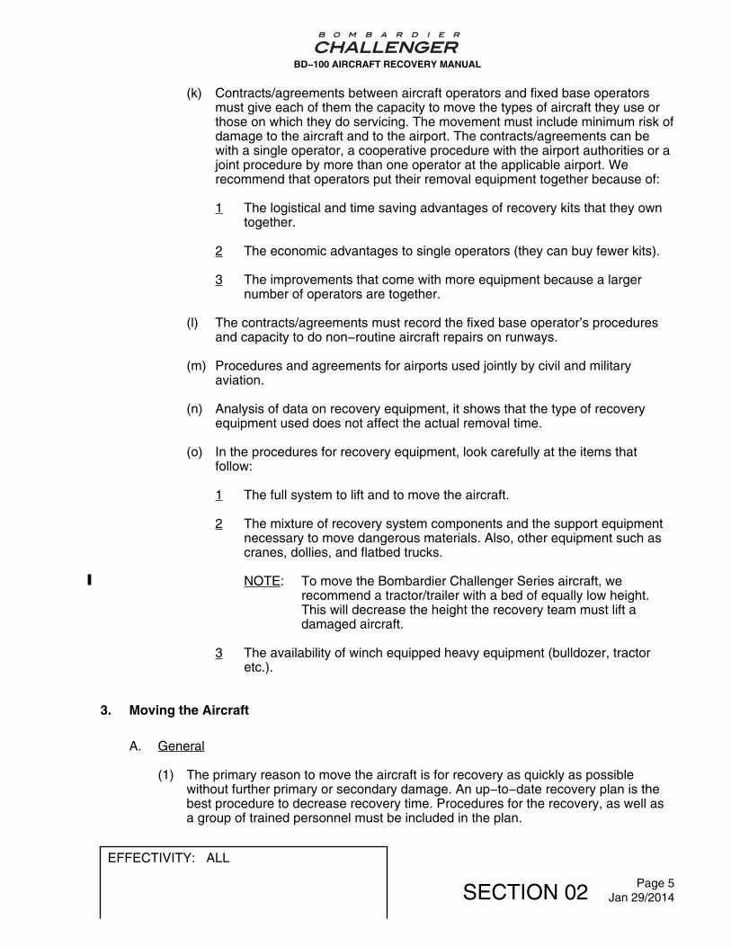
(k) Contracts/agreements between aircraft operators and fixed base operatorsmust give each of them the capacity to move the types of aircraft they use orthose on which they do servicing. The movement must include minimum risk ofdamage to the aircraft and to the airport. The contracts/agreements can bewith a single operator, a cooperative procedure with the airport authorities or ajoint procedure by more than one operator at the applicable airport. Werecommend that operators put their removal equipment together because of:
1 The logistical and time saving advantages of recovery kits that they owntogether.
2 The economic advantages to single operators (they can buy fewer kits).
3 The improvements that come with more equipment because a largernumber of operators are together.
(l) The contracts/agreements must record the fixed base operator’s proceduresand capacity to do non−routine aircraft repairs on runways.
(m) Procedures and agreements for airports used jointly by civil and militaryaviation.
(n) Analysis of data on recovery equipment, it shows that the type of recoveryequipment used does not affect the actual removal time.
(o) In the procedures for recovery equipment, look carefully at the items thatfollow:
1 The full system to lift and to move the aircraft.
2 The mixture of recovery system components and the support equipmentnecessary to move dangerous materials. Also, other equipment such ascranes, dollies, and flatbed trucks.
NOTE: To move the Bombardier Challenger Series aircraft, werecommend a tractor/trailer with a bed of equally low height.This will decrease the height the recovery team must lift adamaged aircraft.
3 The availability of winch equipped heavy equipment (bulldozer, tractoretc.).
3. Moving the Aircraft
A. General
(1) The primary reason to move the aircraft is for recovery as quickly as possiblewithout further primary or secondary damage. An up−to−date recovery plan is thebest procedure to decrease recovery time. Procedures for the recovery, as well asa group of trained personnel must be included in the plan.
BD−100 AIRCRAFT RECOVERY MANUAL
EFFECTIVITY: ALL
SECTION 02 Page 5Jan 29/2014

(2) A correct estimate of the damage to the aircraft is very important. This will help tofind, in the shortest time, the procedure to do the recovery operation.
B. Steps and Recommendations for an Efficient Aircraft Recovery
(1) Before you start a recovery operation, make sure of the correct safety precautions:
(a) Remove the aircraft batteries as quickly as possible. If it is not possible toremove the batteries, disconnect and insulate the battery connectors. Refer toFigure 1 for battery locations.
(b) Close oxygen bottle valve.
(c) If necessary, defuel the damaged aircraft to increase the speed of the recoveryoperation.
NOTE: Follow the applicable local regulations concerning defueling.
(2) Examine how the accident occurred. This will help to make an estimate of thedamage that occurred to the aircraft.
(3) After a check of the obvious damage, examine the structural condition of theaircraft.
(4) Look for possible damage to other areas of the aircraft. The following areindications of damage:
(a) Bulges in the wing or fuselage skin panels, at structural joints, or heavy fittings,are indications of internal damage.
(b) Rivets, bolts, or fasteners of all types that tilt, are cut or loose, are alsoindications of damage.
(c) Torn, cracked or buckled fairings and other non−structural parts are causes forclose inspection of the structure below them. Think that damage to thestructure below these parts is possible until a close inspection showsdifferently.
NOTE: A close inspection may not be possible if the aircraft is wheels−up.
(5) Make a list of missing or unserviceable items as you make an estimate of thedamage.
BD−100 AIRCRAFT RECOVERY MANUAL
EFFECTIVITY: ALL
SECTION 02 Page 6Oct 25/2007
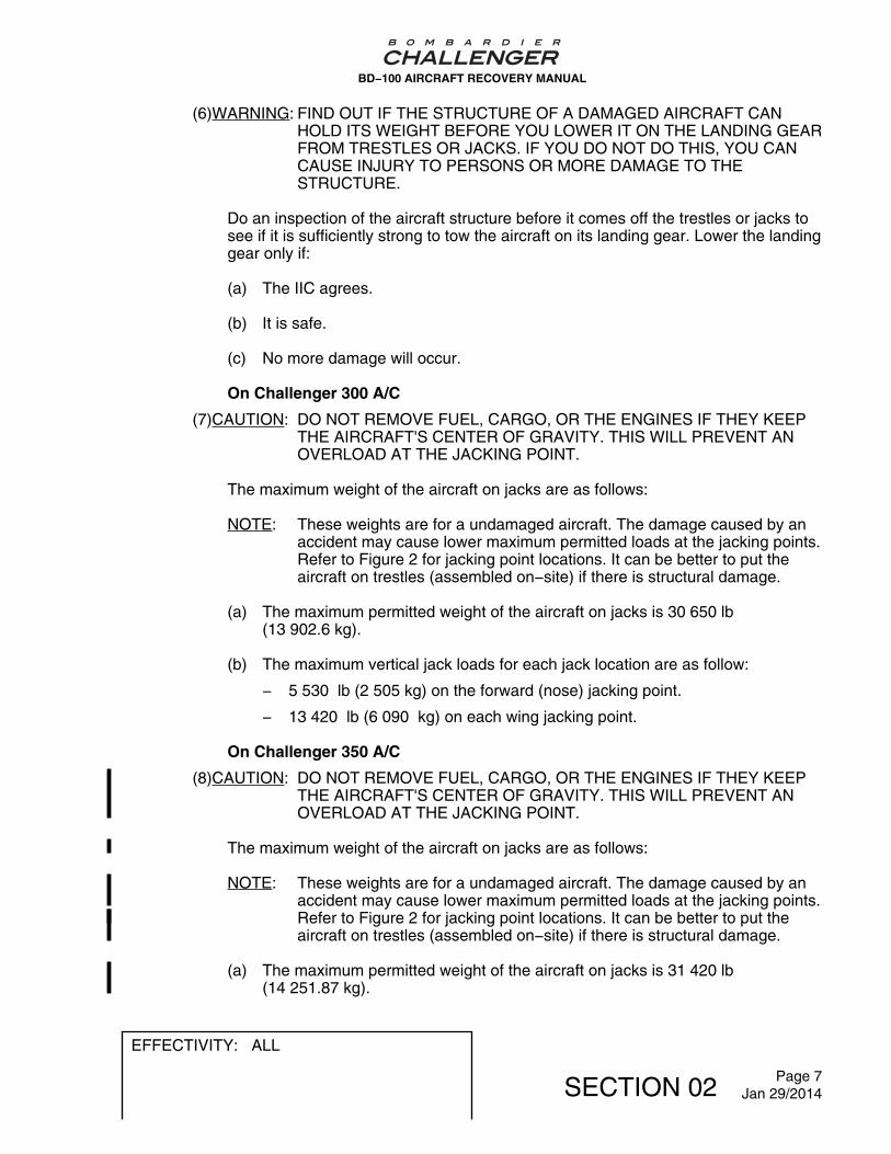
(6)WARNING: FIND OUT IF THE STRUCTURE OF A DAMAGED AIRCRAFT CANHOLD ITS WEIGHT BEFORE YOU LOWER IT ON THE LANDING GEARFROM TRESTLES OR JACKS. IF YOU DO NOT DO THIS, YOU CANCAUSE INJURY TO PERSONS OR MORE DAMAGE TO THESTRUCTURE.
Do an inspection of the aircraft structure before it comes off the trestles or jacks tosee if it is sufficiently strong to tow the aircraft on its landing gear. Lower the landinggear only if:
(a) The IIC agrees.
(b) It is safe.
(c) No more damage will occur.
On Challenger 300 A/C
(7)CAUTION: DO NOT REMOVE FUEL, CARGO, OR THE ENGINES IF THEY KEEPTHE AIRCRAFT'S CENTER OF GRAVITY. THIS WILL PREVENT ANOVERLOAD AT THE JACKING POINT.
The maximum weight of the aircraft on jacks are as follows:
NOTE: These weights are for a undamaged aircraft. The damage caused by anaccident may cause lower maximum permitted loads at the jacking points.Refer to Figure 2 for jacking point locations. It can be better to put theaircraft on trestles (assembled on−site) if there is structural damage.
(a) The maximum permitted weight of the aircraft on jacks is 30 650 lb(13 902.6 kg).
(b) The maximum vertical jack loads for each jack location are as follow:
− 5 530 lb (2 505 kg) on the forward (nose) jacking point.
− 13 420 lb (6 090 kg) on each wing jacking point.
On Challenger 350 A/C
(8)CAUTION: DO NOT REMOVE FUEL, CARGO, OR THE ENGINES IF THEY KEEPTHE AIRCRAFT'S CENTER OF GRAVITY. THIS WILL PREVENT ANOVERLOAD AT THE JACKING POINT.
The maximum weight of the aircraft on jacks are as follows:
NOTE: These weights are for a undamaged aircraft. The damage caused by anaccident may cause lower maximum permitted loads at the jacking points.Refer to Figure 2 for jacking point locations. It can be better to put theaircraft on trestles (assembled on−site) if there is structural damage.
(a) The maximum permitted weight of the aircraft on jacks is 31 420 lb(14 251.87 kg).
BD−100 AIRCRAFT RECOVERY MANUAL
EFFECTIVITY: ALL
SECTION 02 Page 7Jan 29/2014

(b) The maximum vertical jack loads for each jack location are as follow:
− 5 327 lb (2 416kg) on the forward (nose) jacking point.
− 13 830 lb (6 273 kg) on each wing jacking point.
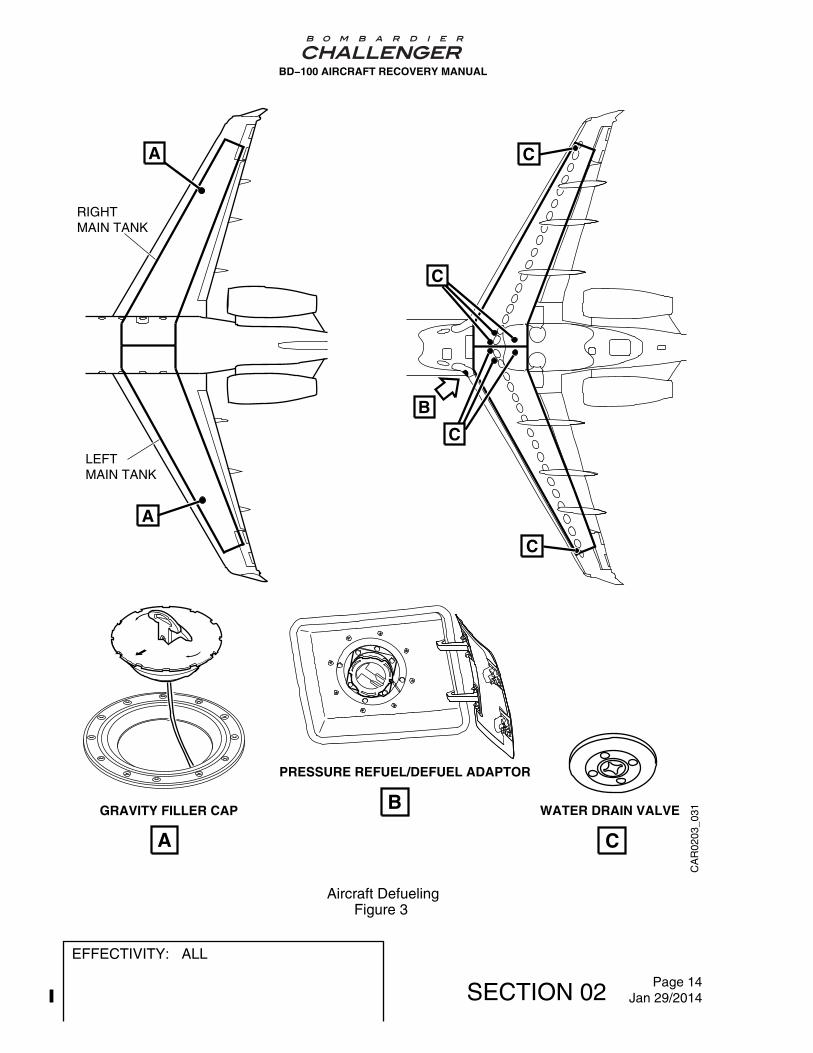
(9) If required, remove the baggage and cargo from the aircraft. The baggagecompartment door opens in and up.
(10) Examine the damage to the fuel system to find the best procedure to defuel theaircraft. The single−point refuel/defuel adaptor, fuel lines and tanks can havedamage. Refer to Figure 3.
(11) Alternative procedures to defuel the aircraft are as follows:
NOTE: Follow the applicable local regulations concerning defueling.
(a) Suction defueling procedure.
1 The suction will break when one of the inlet points becomes open. Thisprocedure is slow and can mean that the fuel tank is not fully drained.
(b) Gravity defueling procedure.
WARNING: MAKE SURE THAT THE FUEL LEVEL IN THE TANK IS BELOWTHE OPENING OF THE GRAVITY FUELING ADAPTER. IF IT ISNOT, FUEL WILL SPILL OUT OF THE TANK. THIS CAN CAUSEINJURY TO PERSONS.
1 Fuel will come out from the tank(s) if the tank is higher than the gravityfuel adaptor. To prevent this, make sure the fuel level in the tank is belowthe gravity fueling adaptor before opening.
2 If available, use a gravity defueling adaptor to drain fuel from theunderwing fuel drains into approved containers. Use the suctionprocedure at the single point refuel/defuel position. Use a suction hose inthe overwing and center tank gravity fueling adapter to remove the fuel ifit is not possible to remove it through the pressure refuel/defuel adaptor.
3 The quantity of fuel in the tank and the attitude of the aircraft will controlthe amount of fuel you can remove.
(12)WARNING:BEFORE YOU REMOVE THE ENGINE, MAKE SURE THAT THEAIRCRAFT IS STABLE. IF IT IS NOT STABLE, THE AIRCRAFT CANFALL AND CAUSE INJURY TO PERSONS AND DAMAGE TO THEAIRCRAFT.
If the engines have to be removed to keep the weight and balance, make sure theaircraft is level before the release of the load on the yokes. The aircraft must alsobe stable to prevent movement because of an imbalance when an engine isremoved.
BD−100 AIRCRAFT RECOVERY MANUAL
EFFECTIVITY: ALL
SECTION 02 Page 8Jan 29/2014

On Challenger 300 A/C
(13) In recovery operations, there are two basic situations that will occur:
− You can tow the aircraft on its landing gear.
− You must lift the aircraft on to a transport.
(a) If the landing gear stays serviceable after the aircraft has run off the runway ortaxiway, it may be possible to tow it by the main landing gear (Refer to Section6, Figure 3).
(b) If the landing gear has flat tire(s), there are some tow limits. Refer to Figure 4for towing restriction with flat tire.
(c) Make an estimate of the ground’s load−bearing capacity and the slope of theterrain in the recovery area. Make the path to tow the aircraft as smooth aspossible if it does not have concrete or asphalt. Refer to Figure 5 for landinggear measurements and tire pressures.
(d) If the landing gear is unserviceable, use pneumatic lifting bags or cranes andslings to lift the aircraft. Then put it on dollies or on a flatbed trailer.
On Challenger 350 A/C
(14) In recovery operations, there are two basic situations that will occur:
− You can tow the aircraft on its landing gear.
− You must lift the aircraft on to a transport.
(a) If the landing gear stays serviceable after the aircraft has run off the runway ortaxiway, it may be possible to tow it by the main landing gear (Refer to Section6, Figure 3).
(b) If the landing gear has flat tire(s), there are some tow limits. Refer to Figure 4for towing restriction with flat tire.
(c) Make an estimate of the ground’s load−bearing capacity and the slope of theterrain in the recovery area. Make the path to tow the aircraft as smooth aspossible if it does not have concrete or asphalt. Refer to Figure 6 for landinggear measurements and tire pressures.
(d) If the landing gear is unserviceable, use pneumatic lifting bags or cranes andslings to lift the aircraft. Then put it on dollies or on a flatbed trailer.
BD−100 AIRCRAFT RECOVERY MANUAL
EFFECTIVITY: ALL
SECTION 02 Page 9Jan 29/2014

(15)CAUTION:INFLATE THE FORWARD AND AFT LIFTING BAGS SUFFICIENTLY TOKEEP THE AIRCRAFT STABLE. PUT THE BAGS IN AREAS OFSUFFICIENT STRENGTH TO PREVENT MORE DAMAGE TO THEAIRCRAFT.
Lift an aircraft that is on its fuselage with lifting bags put below each wing, theforward fuselage and the aft fuselage. Refer to Figure 7 for the recommendedposition of the pneumatic bags. Keep the aircraft stable with cables while you lift it,or while it is on the pneumatic bags. Inflate the pneumatic bags sufficiently to allowthe installation of trestles or jacks at the nose, wings and the rear fuselage support.Put the cables at the nose jack point and the rear mooring points.
(16) Use a nose jack and normal jacking procedures to lift a nose−down aircraft aroundthe MLG axis.
(17) When you use cranes and slings to lift the aircraft, you must make an estimate ofthe damage to the structure. This will help to find how much damage has occurredand the location of strong frames to transmit the sling loads. Because each aircraftrecovery operation is different, Bombardier cannot recommend special slinglocations. Generally, use the nose jacking point (FS319.75), the passenger door aftframe and the forward engine mounts to lift the aircraft. Refer to Figure 8 for thestrongest frames locations.
(18) Lift the aircraft only in periods of very light or no winds. Because of the large areasof wing, empennage and fuselage, small gusts of wind can cause large pendulummovements.
(19) Make the aircraft stable during the lift. To help control its movements during the lift,attach ropes to available strong points, such as the landing gear. If the engines areremoved, attach ropes to the forward engine mounts. During the lift, first level theaircraft then lift it sufficiently high to put it on jacks or a flatbed trailer.
(20) If the aircraft cannot move on its landing gear, move it on a flatbed trailer. Refer toFigure 8.
(21) Cranes and slings can be faster and easier to use in the recovery of the BombardierChallenger Series aircraft.
BD−100 AIRCRAFT RECOVERY MANUAL
EFFECTIVITY: ALL
SECTION 02 Page 10Jan 29/2014

CA
R02
01_0
01
A
BATTERIES
A
BD−100 AIRCRAFT RECOVERY MANUAL
Aircraft BatteriesFigure 1 (Sheet 1 of 2)
EFFECTIVITY: ALL
SECTION 02 Page 11Jan 29/2014

CA
R02
01_0
02
B
B
FS227.50
STANDBY INSTRUMENTBATTERY
COMPARTMENTACCESS PANEL
MOUNTINGTRAY
HOLD−DOWNSCREW
CAMLOCKS
BATTERY
BD−100 AIRCRAFT RECOVERY MANUAL
Aircraft BatteriesFigure 1 (Sheet 2 of 2)
EFFECTIVITY: ALL
SECTION 02 Page 12Jan 29/2014

CA
R0
20
2_
00
1
BL161.94 BL161.94
A B
B
C
AAA
FS636.12 FS826.60
CAFS319.75
A
FUSELAGESUPPORTSHORINGBEAM
JACKINGPOINT
JACKPAD
NYLONPLUG
REAR FUSELAGESUPPORTTYPICAL JACK
BD−100 AIRCRAFT RECOVERY MANUAL
Structural Jacking Points and AdaptersFigure 2
EFFECTIVITY: ALL
SECTION 02 Page 13Jan 29/2014
RIGHTMAIN TANK
A
A
LEFTMAIN TANK
B
C
C
C
C
GRAVITY FILLER CAP
PRESSURE REFUEL/DEFUEL ADAPTOR
WATER DRAIN VALVE
A
B
C
CA
R02
03_0
31
BD−100 AIRCRAFT RECOVERY MANUAL
Aircraft DefuelingFigure 3
EFFECTIVITY: ALL
SECTION 02 Page 14Jan 29/2014

CA
R02
_041
ITEMNO.
MAIN GEARCONDITION
TIRE FOOTPRINTEXAMPLES
PERMITTEDTO TAXI?
PERMITTEDTO TOW?
DISTANCEPERMITTED
TO TAXIAND TOW
NOSE WHEELANGLE OF TURN
REMARKS
1
2
3
4
5
6
7
ONLY ONEFLAT TIRE(ANY TIRE)
TWO FLAT TIRES(ONE ON EACH
AXLES)
TWO FLAT TIRES(ON ONE AXLES)
THREE FLAT TIRES(ANY COMBINATION)
FOUR FLAT TIRES
ONE FLAT TIRE
TWO FLAT TIRES
YES
YES
YES
YES
YES
YES
YES
YES
YES
YES
YESBOTH MAINGEAR ONLY
(BRIDLE)
YESBOTH MAINGEAR ONLY
(BRIDLE)
YESBOTH MAINGEAR ONLY
(BRIDLE)
NOSE GEAR CONDITION
YESBOTH MAINGEAR ONLY
(BRIDLE)
UNLIMITED
MINIMUM TOCLEAR
RUNWAY
MINIMUM TOCLEAR
RUNWAY
MINIMUM TOCLEAR
RUNWAY
MINIMUM TOCLEAR
RUNWAY
UNLIMITED
UNLIMITED
NORMAL
10 DEGREESMAXIMUM
NORMAL
UNLIMITED
10 DEGREESMAXIMUM
10 DEGREESMAXIMUM
10 DEGREESMAXIMUM
SEE NOTES1, 2, 5
SEE NOTES1, 3, 4, 5
SEE NOTES1, 3, 4, 5, 6
SEE NOTES1, 3, 4, 5, 6
SEE NOTES1, 3, 4, 5, 6
SEE NOTES1, 2, 4
SEE NOTES1, 2, 5, 6
TO TAXI OR TO TOW WITH TWO FLAT TIRES ON
Avoid sharp turns, abrupt starts and stops.
Maximum speed permitted to taxi or to tow aircraft = 5 mph (8kmh).
Maximum to taxi or to tow = 2 mph (3kmh).
After you clear the runway, or if additional tire fails, the airplane should be stoppedand serviceable wheel/tire assembly(ies) installed to obtain item number 2 or 6.
After any tire failure or excessive heat condition the affected wheel assemblymust be inspected per applicable Goodyear Overhaul Manaul prior to futher use.
CAUTION
NOTES
Under a multiple failed tire condition, the affected landing gear assembliesand linkage must be inspected for possible structural damage.
SAME GEAR CAN RESULT IN WHEEL DAMAGE.
1
2
3
4
5
6
BD−100 AIRCRAFT RECOVERY MANUAL
Towing/Taxiing with Flat TiresFigure 4
EFFECTIVITY: ALL
SECTION 02 Page 15Jan 29/2014

CA
R02
05_0
01
CHALLENGER 300
MAXIMUM RAMP WEIGHT
NOSE TIRE PRESSURE
MAIN GEAR TIRE PRESSURE
39,000 (17,690 kg)
109−114 PSI UNLOADED113−119 PSI LOADED151−159 PSI UNLOADED157−165 PSI LOADED
10 ft 6 in(3.20 m)
17.7 in(45.00 cm)
11.6 in(29.46 cm)
27 ft 9 in(8.46 m)
BD−100 AIRCRAFT RECOVERY MANUAL
Landing Gear MeasurementsFigure 5
EFFECTIVITY: ALL
SECTION 02 Page 16Jan 29/2014

CHALLENGER 350
MAXIMUM RAMP WEIGHT
NOSE TIRE PRESSURE
MAIN GEAR TIRE PRESSURE
109−114 PSI UNLOADED113−119 PSI LOADED151−159 PSI UNLOADED157−165 PSI LOADED
10 ft 6 in(3.20 m)
17.7 in(45.00 cm)
11.6 in(29.46 cm)
27 ft 9 in(8.46 m)
BA
R0
20
5_
00
1
BD−100 AIRCRAFT RECOVERY MANUAL
Challenger 350 − Landing Gear MeasurementsFigure 6
EFFECTIVITY: ALL
SECTION 02 Page 17Jan 29/2014

CA
R02
06_0
01AIR SUPPLY
BD−100 AIRCRAFT RECOVERY MANUAL
Lifting with Pneumatic BagsFigure 7
EFFECTIVITY: ALL
SECTION 02 Page 18Jan 29/2014

CA
R0
20
7_
00
1
A B
C
SLING ASSEMBLY12 in (305 mm)WIDE STRAP
SLING ASSEMBLY12 in (305 mm)WIDE STRAP
FS319.75
FS375.00
NOTE
12 in (305 mm) wide strap preferred,10 in (254 mm) wide strap minimum,check sling load rating anduse multiple slings to carryload safely.
BD−100 AIRCRAFT RECOVERY MANUAL
Aircraft Recovery with Cranes and SlingsFigure 8 (Sheet 1 of 2)
EFFECTIVITY: ALL
SECTION 02 Page 19Jan 29/2014

CA
R02
07_0
02
A
C
WING JACK POINT BEAM
B
REAR FUSELAGE SUPPORT
FORWARD ENGINEMOUNT (FS724.70)
BD−100 AIRCRAFT RECOVERY MANUAL
Aircraft Recovery with Cranes and SlingsFigure 8 (Sheet 2 of 2)
EFFECTIVITY: ALL
SECTION 02 Page 20Jan 29/2014

4. Terrain Consideration
A. General
(1) Type of terrain, weather conditions and structural damage to the aircraft are factorsto find the bearing area necessary to lift and move the aircraft. Get an experiencedcivil engineer or earthworks contractor to make an assessment of the terrainsurface conditions, bearing loads and areas.
B. Factors to Find the Most Practical Recovery Plan
(1) Make an estimate of the general terrain to find the best routing to tow the aircraft.Structural damage to the aircraft can occur if it moves over terrain that is notsmooth. If necessary, grade the proposed tow routing to give a smooth surface forthe aircraft and tow vehicle(s).
(2) Make an estimate of how hard and smooth the surface is. Also, the possible effectof rainfall and drainage on the load−bearing capacity of the terrain. Find the safebearing load and surface area of the terrain. The ground must have the samecondition for a depth of 8 in (20.3 mm), because the force necessary to tow anaircraft changes as a function of the strength of the terrain.
(3) The type of terrain shows the applicable procedure to lift the aircraft:
(a) Refer to Figure 2 for the use of jacks .
(b) Refer to Figure 7 for the use of pneumatic bags.
(c) Refer to Figure 8 for the use of mobile cranes and slings.
C. Ground Conditions
(1) Ground conditions are one of the primary factors in aircraft recovery operations.Ground conditions have an effect on decisions to tow the aircraft, put tethers in theground, or set shoring (cribbing). From the results of ground tests, the recoveryteam makes decisions about reinforcement of the terrain and the shoring (cribbing)base.
(2) The California Bearing Ratio (CBR) is known as the standard for different groundconditions.
(a) For ground conditions that are related to shoring the aircraft (Refer to Table 1).
BD−100 AIRCRAFT RECOVERY MANUAL
EFFECTIVITY: ALL
SECTION 02 Page 21Jan 29/2014

(b) For the related bearing strength of different ground conditions (Refer to Table2).
Table 1 − Ground Conditions To Shore the Aircraft
Surface Type Shoring (Cribbing) Necessary For LoadsThat Roll
Shoring (Cribbing) Necessary For LoadsTo Jack
Max AllowableContact
Pressure
Minimum ContactArea Needed
Max AllowableContact
Pressure
Minimum ContactArea Needed
psi kPa Each2 000lb/in²
Each141.61kg/cm²
psi kPa Each2 000lb/in²
Each141.61kg/cm²
Soft WetClay orWetOrganicTerrain
18.0 124.0 111.0 7.8 8.0 55.0 2 500.0 175.77
LooseSand orSandyTerrain
65.0 448.0 31.0 2.18 35.0 241.0 571.0 40.15
Sand withClay
100.0 690.0 20.0 1.41 50.0 345.0 400.0 28.12
WellGradedSand andMediumClay
180.0 1 241.0
11.0 0.77 85.0 586.0 235.0 16.52
SandyGravel,Clay−Gravelor Dry Clay
300.0 2068.0
6.7 0.47 165.0 1 138.0
121.0 8.51
CompactedSandyClay−Gravel
N/A N/A N/A N/A 200.0 1 379.0
100.0 7.03
BD−100 AIRCRAFT RECOVERY MANUAL
EFFECTIVITY: ALL
SECTION 02 Page 22Jan 29/2014

Table 2 − California Bearing Ratio (CBR) Soil Bearing Strength
Surface Type Safe Bearing Load Approximate Bearing Area Necessary
10 000 lb 5 000 kg
psi kPa in² ft² m²
Slate or Rock 230.0 1 586.0 44.0 0.31 0.062
Concrete 156.0 1 076.0 64.0 0.54 0.091
Hard Pan and SmallGravel or Sand
138.0 951.0 72.5 0.50 0.103
Small Gravel and Sand 100.0 689.0 100.0 0.69 0.142
Gravel, Course Sand orMedium Clay
62.0 427.0 161.0 1.12 0.229
Loose Sand and GravelMixture
42.0 290.0 238.0 1.65 0.340
Medium stiff Clay 35.0 241.0 286.0 1.98 0.407
Loose Sand 30.0 207.0 333.0 2.31 0.474
Soft Clay or Earth 15.5 107.0 645.0 4.48 0.917
BD−100 AIRCRAFT RECOVERY MANUAL
EFFECTIVITY: ALL
SECTION 02 Page 23Jan 29/2014


AIRCRAFT - GENERAL
1. Model Designation and Type
A. The Bombardier Challenger Series Business Jet is made by Bombardier Aerospace. Theaircraft is swept−wing monoplane with pressurized cabin, operated by two crew.
B. The aircraft has two Honeywell AS907 Turbofan engines.
2. Aircraft Dimensions
On Challenger 300 A/C
A. Refer to Figure 1 for all basic dimensions, including ground clearances.
On Challenger 350 A/C
B. Refer to Figure 2 for all basic dimensions, including ground clearances.
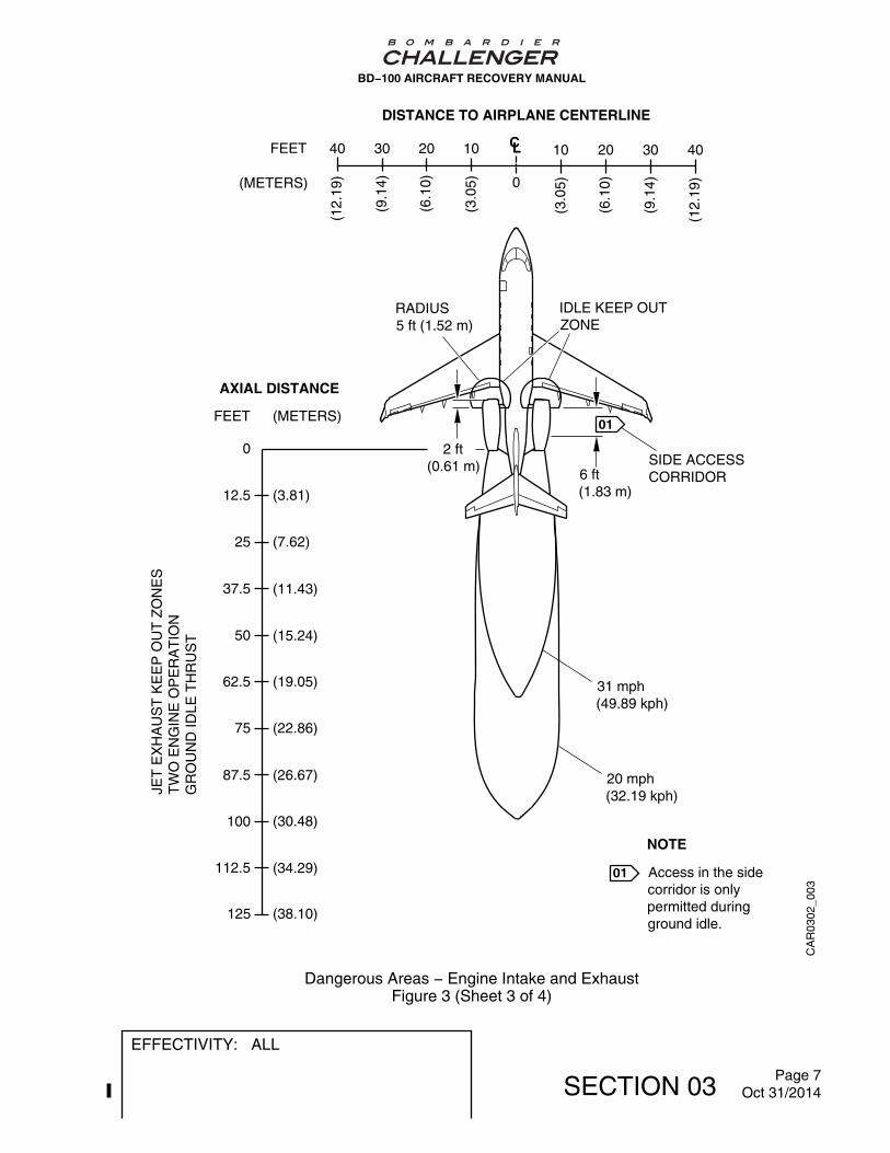
3. Dangerous Areas
A. Persons who do aircraft recovery operations must know of the dangerous areas aroundthe engines and the APU. Refer to Figure 3.
4. Doors
A. The aircraft has the doors that follow:
− Passenger/crew entrance door,
− Baggage compartment door on the left side of the aircraft,
− Aft equipment compartment door at the bottom of the rear fuselage,
− Different small service and access doors,
− Overwing emergency exit door located on the right side of the passengercompartment.
NOTE: The entrance stairs attach to the passenger/crew door.
5. Composite Materials
A. Composite materials such as: Kevlar, Graphite, Fiberglass and Fiberlam are used inmany components of the Bombardier Challenger Series aircraft. Refer to Figure 4 for thelocations of the composite materials.
BD−100 AIRCRAFT RECOVERY MANUAL
EFFECTIVITY: ALL
SECTION 03 Page 1Oct 31/2014
6. Interior Configurations
A. Internal configurations will change according to customer options installed at thecompletion centers.
BD−100 AIRCRAFT RECOVERY MANUAL
EFFECTIVITY: ALL
SECTION 03 Page 2Jan 29/2014

CA
R03
01_0
01
7 ft 11 in(2.41 m)
14 ft 11 in(4.55 m)
7 ft 8 in(2.34 m)
28 ft 1 in(8.56 m)
23 ft 9 in(7.24 m)
3 ft 9 in(1.14 m)
63 ft 10 in(19.46 m)
10 ft 6 in(3.20 m)
12 ft(3.66 m)
2 ft 6 in(0.76 m)
4 ft 3 in(1.30 m)
61 ft 1 in(18.62 m) 68 ft 9 in
(20.96 m)
20 ft(6.10 m)
5 ft 4 in(1.63 m)
2 ft(0.61 m)
3
PASSENGER COMPARTMENTDIMENSIONS
LENGTHWIDTH (FLOOR LINE)
WIDTHCENTERLINE
HEIGHT
VOLUME
FLOOR AREA 146 ft 2
896 ft
6 ft 1 in7 ft 2 in
5 ft 1 in
28 ft 7 in
13.56 m 2
25.37 m3
1.85 m2.18 m
1.55 m
8.71 m
3 ft(0.91 m)
27 ft 9 in(8.46 m)
01
01
NOTES
Measurement at manufacturerempty weight.
11 ft 11 in(3.63 m)
OVER−WINGEMERGENCY EXIT1 ft 8 in x 3 ft(0.51 m x 0.76 m)
6 ft 2 in(1.88 m)
BD−100 AIRCRAFT RECOVERY MANUAL
Challenger 300 − Aircraft Basic Dimensions & Ground ClearancesFigure 1
EFFECTIVITY: ALL
SECTION 03 Page 3Oct 31/2014

BA
R0
30
1_
00
1
7 ft 11 in(2.41 m)
14 ft 11 in(4.55 m)7 ft 8 in
(2.34 m)
30 ft 8 in(9.35 m)
23 ft 9 in(7.24 m)
3 ft 9 in(1.14 m)
69 ft(21.03 m)
10 ft 6 in(3.20 m)
12 ft(3.66 m)
2 ft 6 in(0.76 m)
4 ft 3 in(1.30 m)
61 ft 1 in(18.62 m)
68 ft 9 in(20.96 m)
20 ft(6.10 m)
5 ft 4 in(1.63 m)
2 ft(0.61 m)
3 ft(0.91 m)
27 ft 9 in(8.46 m)
3.5°
2.0°
3
PASSENGER COMPARTMENTDIMENSIONS
146 ft 2
896 ft
6 ft 1 in
7 ft 2 in
5 ft 1 in
28 ft 7 in
13.56 m 2
25.37 m3
1.85 m
2.18 m
1.55 m
8.71 mWIDTH(FLOOR LINE)
LENGTH
WIDTHCENTERLINEHEIGHT
VOLUME
FLOOR AREA
NOTES
Measurement at manufacturerempty weight.
01
01
11 ft 11 in(3.63 m)
BD−100 AIRCRAFT RECOVERY MANUAL
Challenger 350 − Aircraft Basic Dimensions & Ground ClearancesFigure 2
EFFECTIVITY: ALL
SECTION 03 Page 4Oct 31/2014

CA
R03
02_0
01
01
NOTE
0
12.5
25
37.5
50
62.5
75
87.5
100
112.5
125
(3.81)
(7.62)
(11.43)
(15.24)
(19.05)
(22.86)
(26.67)
(30.48)
(34.29)
(38.10)
01
AXIAL DISTANCE
FEET (METERS)
JET
EX
HA
US
T K
EE
P O
UT
ZO
NE
SS
ING
LE E
NG
INE
OP
ER
AT
ION
GR
OU
ND
IDLE
TH
RU
ST
31 mph(49.89 kph)
20 mph(32.19 kph)
IDLE KEEP OUTZONERADIUS
5 ft (1.52 m)
2 ft(0.61 m)
6 ft(1.83 m)
SIDE ACCESSCORRIDOR
DISTANCE TO AIRPLANE CENTERLINE
CLFEET
(METERS)
10203040
(3.0
5)
(6.1
0)
(9.1
4)
(12.
19) 0
Access in the sidecorridor is onlypermitted duringground idle.
10 20 30 40
(3.0
5)
(6.1
0)
(9.1
4)
(12.
19)
BD−100 AIRCRAFT RECOVERY MANUAL
Dangerous Areas − Engine Intake and ExhaustFigure 3 (Sheet 1 of 4)
EFFECTIVITY: ALL
SECTION 03 Page 5Oct 31/2014

CA
R03
02_0
02
01
NOTE
0
12.5
25
37.5
50
62.5
75
87.5
100
112.5
125
(3.81)
(7.62)
(11.43)
(15.24)
(19.05)
(22.86)
(26.67)
(30.48)
(34.29)
(38.10)
01
AXIAL DISTANCE
FEET (METERS)
JET
EX
HA
US
T K
EE
P O
UT
ZO
NE
SS
ING
LE E
NG
INE
OP
ER
AT
ION
TA
KE
−O
FF
TH
RU
ST
164 mph(263.93 kph)
109 mph(175.41 kph)
TAKE−OFF POWERKEEP OUT ZONE
RADIUS15 ft (4.57 m)
SIDE ACCESSCORRIDOR
DISTANCE TO AIRPLANE CENTERLINE
CL
0
Access in theside corridor isprohibited aboveidle power.
55 mph(88.51 kph)
TO 195 ft(59.44 m)
6 ft(1.83 m)
FEET
(METERS)
10203040
(3.0
5)
(6.1
0)
(9.1
4)
(12.
19)
10 20 30 40
(3.0
5)
(6.1
0)
(9.1
4)
(12.
19)
BD−100 AIRCRAFT RECOVERY MANUAL
Dangerous Areas − Engine Intake and ExhaustFigure 3 (Sheet 2 of 4)
EFFECTIVITY: ALL
SECTION 03 Page 6Oct 31/2014
CA
R03
02_0
03
01
0
12.5
25
37.5
50
62.5
75
87.5
100
112.5
125
(3.81)
(7.62)
(11.43)
(15.24)
(19.05)
(22.86)
(26.67)
(30.48)
(34.29)
(38.10)
AXIAL DISTANCE
FEET (METERS)
JET
EX
HA
US
T K
EE
P O
UT
ZO
NE
ST
WO
EN
GIN
E O
PE
RA
TIO
NG
RO
UN
D ID
LE T
HR
US
T
31 mph(49.89 kph)
20 mph(32.19 kph)
RADIUS5 ft (1.52 m)
2 ft(0.61 m)
6 ft(1.83 m)
SIDE ACCESSCORRIDOR
DISTANCE TO AIRPLANE CENTERLINE
CL
NOTE
01 Access in the sidecorridor is onlypermitted duringground idle.
FEET
(METERS)
10203040
(3.0
5)
(6.1
0)
(9.1
4)
(12.
19) 0
10 20 30 40
(3.0
5)
(6.1
0)
(9.1
4)
(12.
19)
IDLE KEEP OUTZONE
BD−100 AIRCRAFT RECOVERY MANUAL
Dangerous Areas − Engine Intake and ExhaustFigure 3 (Sheet 3 of 4)
EFFECTIVITY: ALL
SECTION 03 Page 7Oct 31/2014

CA
R03
02_0
04
01
0
12.5
25
37.5
50
62.5
75
87.5
100
112.5
125
(3.81)
(7.62)
(11.43)
(15.24)
(19.05)
(22.86)
(26.67)
(30.48)
(34.29)
(38.10)
AXIAL DISTANCE
FEET (METERS)
JET
EX
HA
US
T K
EE
P O
UT
ZO
NE
ST
WO
EN
GIN
E O
PE
RA
TIO
NT
AK
E−
OF
F T
HR
US
T
164 mph(263.93 kph)
109 mph(175.41 kph)
TAKE−OFF POWERKEEP OUT ZONES
RADIUS15 ft (4.57 m)
SIDE ACCESSCORRIDOR
DISTANCE TO AIRPLANE CENTERLINE
CL
55 mph(88.51 kph)
TO 195 ft(59.44 m)
NOTE
01 Access in theside corridor isprohibited aboveidle power.
FEET
(METERS)
10203040
(3.0
5)
(6.1
0)
(9.1
4)
(12.
19) 0
10 20 30 40
(3.0
5)
(6.1
0)
(9.1
4)
(12.
19)
BD−100 AIRCRAFT RECOVERY MANUAL
Dangerous Areas − Engine Intake and ExhaustFigure 3 (Sheet 4 of 4)
EFFECTIVITY: ALL
SECTION 03 Page 8Oct 31/2014

ELEVATORS
HORIZONTALSTABILIZER
RUDDER
DORSALFAIRING
ENGINECOWLS
CABINFLOOR
VERTICALSTABILIZERLEADING EDGE
THRUST REVERSERPIVOT DOORSOUTER SKIN
FLAPS
GROUNDSPOILERS
MULTI−FUNCTIONSPOILERS
WINGLETS
RADOME
NOSE LANDINGGEAR DOORS
WHEELBINS
AILERON
BELLYFAIRINGS
KEVLAR
GRAPHITE
FIBERGLASS
LEGEND
V−STAB FORWARDBULLET FAIRINGLH AND RH FORWARDACCESS PANELS
V−STAB AFTBULLET FAIRING,AND AFT CONE
TAILCONE
(LEFT AND RIGHT)
AFTNLGDOOR
OVER−WINGFAIRINGS
HYBRID
CA
R0
5_
10
1
BIRDSTRIKEBARRIER
STAIRSFLAPFAIRINGS
BD−100 AIRCRAFT RECOVERY MANUAL
Composite MaterialsFigure 4
EFFECTIVITY: ALL
SECTION 03 Page 9Oct 31/2014


EMERGENCY INFORMATION
1. Emergency Access
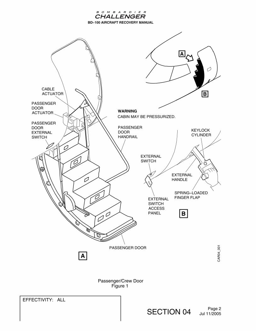
A. Passenger Door
(1) The Passenger Entrance Door is on the left side of the aircraft, just after the flightcompartment. The door serves as a Type I Emergency Exit, Refer to Figure 1.
(2) Dimensions:
− Height 6 ft 2 in (1.88 m)
− Width 2 ft 6 in (0.76 m)
− Height to the sill (one step below the floor line) 4 ft 3 in (1.30 m).
(3) To Open the Passenger Door from the external side do the following:
WARNING: FULLY RELEASE THE CABIN PRESSURE FROM THE AIRCRAFTBEFORE YOU TRY TO OPEN THE DOORS. IF YOU DO NOT DO THIS,THE CABIN PRESSURE CAN DECREASE SUDDENLY. THIS CANCAUSE INJURY TO PERSONS AND DAMAGE TO EQUIPMENT.
WARNING: MAKE SURE THAT THE AREA OUTBOARD OF THE PASSENGERDOOR IS CLEAR BEFORE YOU OPEN THE DOOR. IF YOU DO NOTDO THIS, YOU CAN CAUSE DAMAGE TO EQUIPMENT AND INJURYTO PERSONNEL.
(a) Pull the external door handle outboard and to its top released position.
NOTE: The external door handle will not release if the cabin pressure hasnot lowered to the correct pressure.
(b) Let the passenger door drop by gravity to the full open position.
NOTE: The passenger door actuator will control the decent of the door.
The passenger door will open in less than 9 seconds.
The passenger door telescopic struts will stop the door at the correctposition.
BD−100 AIRCRAFT RECOVERY MANUAL
EFFECTIVITY: ALL
SECTION 04 Page 1Jan 30/2012
CA
R04
_001
A
A
PASSENGERDOORHANDRAIL
PASSENGER DOOR
CABLEACTUATOR
PASSENGERDOORACTUATOR
B
KEYLOCKCYLINDER
EXTERNALHANDLE
SPRING−LOADEDFINGER FLAP
EXTERNALSWITCH
EXTERNALSWITCHACCESSPANEL
B
PASSENGERDOOREXTERNALSWITCH
CABIN MAY BE PRESSURIZED.WARNING
BD−100 AIRCRAFT RECOVERY MANUAL
Passenger/Crew DoorFigure 1
EFFECTIVITY: ALL
SECTION 04 Page 2Jul 11/2005

B. Overwing Emergency−Exit Door
(1) The overwing emergency−exit door is on the right side of the passengercompartment. It opens in and operates from the internal or external side the aircraft.The door serves as a Type III Emergency Exit. Refer to Figure 2.
(2) Dimensions:
− Height 3 ft (0.91 m)
− Width 1 ft 8 in (0.52 m)
(3) To open the overwing emergency−exit door from the external side do the following:
(a) Apply hand pressure on the outside push plate and push the overwing−exitdoor into the aircraft.
(4) To open the overwing emergency−exit door from the inside do as follows:
(a) Pull the upper latch handle marked EXIT PULL.
(b) Hold the overwing emergency−exit door at the lower hand grip and the upperlatch handle.
(c) Tilt the overwing emergency−exit door inboard and lift the door out of thebottom hooks and the pin fittings.
BD−100 AIRCRAFT RECOVERY MANUAL
EFFECTIVITY: ALL
SECTION 04 Page 3Jul 11/2005

CA
R0402_001
AAAA
PUSH IN FLAPPUSH DOOR INWARD
HOOK FITTINGS
HAND GRIP
QUICK−RELEASELATCH MECHANISM
AB
B
BD−100 AIRCRAFT RECOVERY MANUAL
Overwing Emergency−Exit DoorFigure 2
EFFECTIVITY: ALL
SECTION 04 Page 4Jul 11/2005

C. Baggage Door
(1) The baggage compartment door is a plug−type access door on the left hand side ofthe aft fuselage section, forward of the aft pressure bulkhead. Refer to Figure 3.
(2) Dimensions:
− Height 2 ft 6 in (0.76 m)
− Width 2 ft (0.61 m)
− Height to sill floor line 5 ft 4 in (1.62 m).
(3) To open the baggage compartment door with the external handle do as follows:
(a) Push the external handle trigger marked PUSH to let the handle move out.
(b) Turn the external handle counterclockwise to the UNLOCKED position.
(c) Push the door in and up on its tracks until the rollers touch the track stops andthe opening is clear.
(4) To open the baggage compartment door with the internal handle do as follows:
(a) Pull the knob and turn the handle clockwise to release the latch.
(b) Pull the door in and up on the tracks until the rollers contact the track stopsand the opening is clear.
BD−100 AIRCRAFT RECOVERY MANUAL
EFFECTIVITY: ALL
SECTION 04 Page 5Jul 11/2005

CA
R04
03_0
01
B
A
B
INTERNALHANDLE
A
EXTERNALHANDLETRIGGER
EXTERNALHANDLE
BD−100 AIRCRAFT RECOVERY MANUAL
Baggage DoorFigure 3
EFFECTIVITY: ALL
SECTION 04 Page 6Jul 11/2005

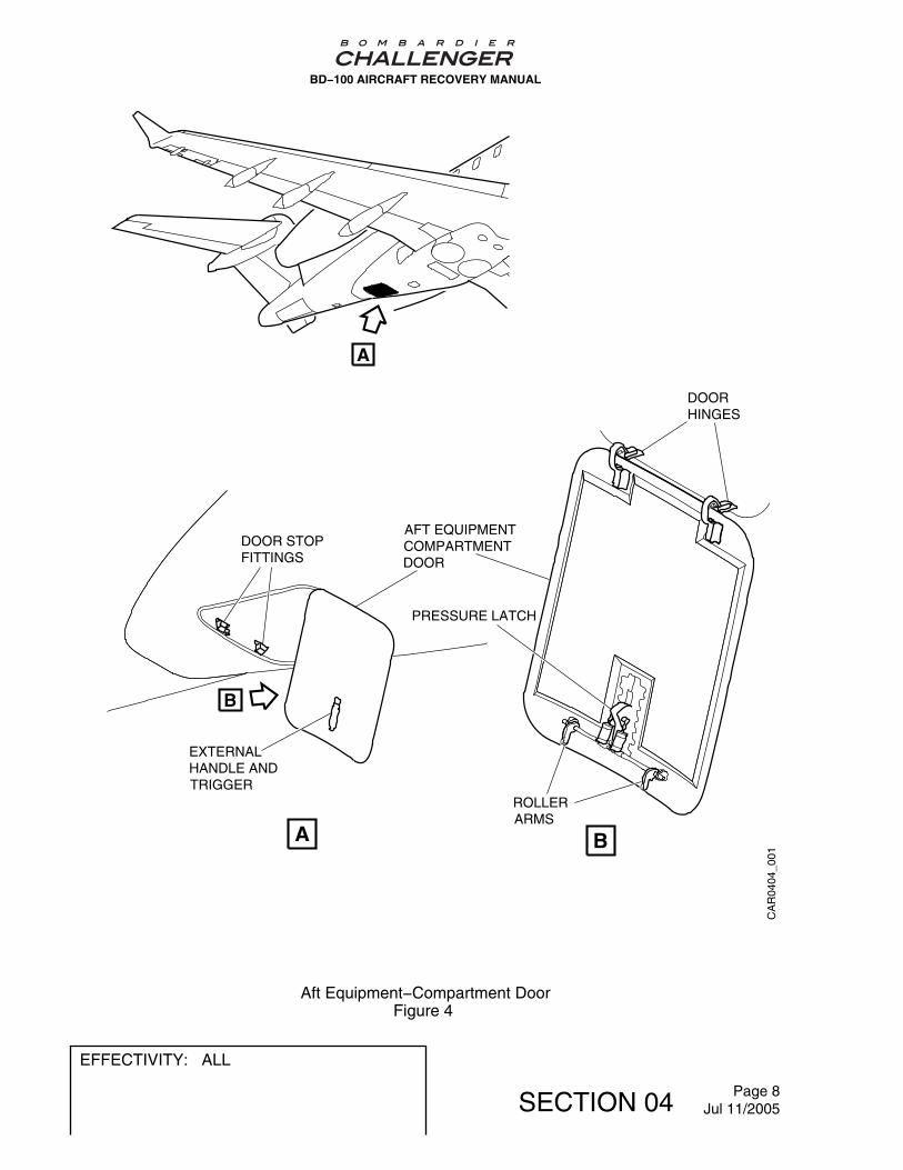
D. Aft Equipment−Compartment Door
(1) The aft equipment compartment of the Bombardier Challenger 300 Business Jet isa non−pressurized area. Access to the aft equipment compartment is through adoor in the aft fuselage fairing. The door has a hinge at the forward end. It opensdown and forward. Refer to Figure 4.
(2) To open the aft equipment−compartment door do as follows:
(a) Push the external handle trigger marked PUSH to let the door handle moveout.
(b) Hold the door, turn the handle clockwise through 90°, and open the door.
BD−100 AIRCRAFT RECOVERY MANUAL
EFFECTIVITY: ALL
SECTION 04 Page 7Jul 11/2005
CA
R04
04_0
01
EXTERNALHANDLE ANDTRIGGER
AFT EQUIPMENTCOMPARTMENTDOOR
PRESSURE LATCH
ROLLERARMS
B
A B
A
DOOR STOPFITTINGS
DOORHINGES
BD−100 AIRCRAFT RECOVERY MANUAL
Aft Equipment−Compartment DoorFigure 4
EFFECTIVITY: ALL
SECTION 04 Page 8Jul 11/2005

E. Service Doors and Panels
(1) The service doors and panels give access to equipment and systems all throughthe fuselage. The service doors and panels are made from light alloy or graphitewith Nomex honeycomb material. Refer to Figure 5.
BD−100 AIRCRAFT RECOVERY MANUAL
EFFECTIVITY: ALL
SECTION 04 Page 9Jul 11/2005

CA
R04
05_0
51
REFUEL/DEFUELDOOR
OXYGEN FILL−AND−INDICATORDOOR
GROUND−POWERACCESS DOOR
REFUEL/DEFUELCONTROL−PANELDOOR
LAVATORY−WASTE SERVICEDOOR
APU ACCESSPANEL
AFT ACCESSPANEL
FORWARD ACCESSPANEL
GROUND−AIRSERVICING−CONNECTION DOOR
BATTERYACCESSDOOR
COMMUNICATIONDOOR
OUTFLOW−VALVEACCESS DOOR
AFT ACCESSPANEL
FORWARD ACCESSPANEL
BD−100 AIRCRAFT RECOVERY MANUAL
Service Doors and PanelsFigure 5
EFFECTIVITY: ALL
SECTION 04 Page 10Jul 11/2005

F. Windshields and Windows
(1) The flight compartment has two windshields and two side windows. The PassengerCompartment has six windows maximum on each side. On the right side of thefuselage, one of the windows is in the Overwing Emergency−Exit Door. All of theother passenger windows attach permanently to their surround structure. Refer toFigure 6.
(2) The windshields are made with layers of acrylic, polyvinyl butyl (PVB) and glass.
(3) The side windows are made with layers of acrylic and PVB.
WARNING: DO NOT TRY TO CHOP THROUGH THE WINDOWS. GO THROUGHTHE EMERGENCY BREAK-IN ZONE. IF YOU DO NOT DO THIS, YOUCAN CAUSE INJURY TO PERSONS.
BD−100 AIRCRAFT RECOVERY MANUAL
EFFECTIVITY: ALL
SECTION 04 Page 11Jul 11/2005

CA
R04
06_0
61
WINDSHIELD
SIDE WINDOWPASSENGERCOMPARTMENTWINDOWS
BD−100 AIRCRAFT RECOVERY MANUAL
WindowsFigure 6
EFFECTIVITY: ALL
SECTION 04 Page 12Jul 11/2005

FIRE FIGHTING
1. General
WARNING: BE VERY CAREFUL NEAR THE OXYGEN BOTTLES IN THE LAVATORYSECTION. THE STANDARD OXYGEN BOTTLE HAS A CAPACITY OF 77 FT³(2.18M³) AND THE OPTIONAL OXYGEN BOTTLE HAS A CAPACITY OF 115 FT³(3.26M³). IF THESE BOTTLES ARE DAMAGED AND RELEASE THE OXYGEN,AN EXPLOSION CAN OCCUR. THIS CAN CAUSE INJURY TO PERSONS ANDDAMAGE TO EQUIPMENT.
WARNING: MAKE SURE THAT YOU DISCONNECT THE ELECTRICAL POWER TO THEENGINE FIRE-EXTINGUISHER BOTTLES. THE EXTINGUISHER BOTTLESHAVE PYROTECHNIC SQUIBS. IF YOU DO NOT DISCONNECT THEELECTRICAL POWER, THERE CAN BE AN EXPLOSION. THIS CAN CAUSEINJURY TO PERSONS AND DAMAGE TO EQUIPMENT.
A. The sentences below give the classes used for fire fighting.
− For brake and wheel fires use only dry powder or class D fire extinguishers.
− For all other parts of the aircraft use class B or C fire extinguishers.
Aerodrome Category for Rescue and Fire Fighting
Category Regulation
International Civil AviationOrganization (ICAO)
4 ICAO Annex 14 −Aerodrome
Federal AviationAdministration (FAA)
A FAR 139.315
Transport Canada (TC) 4 CAR 303 Supart 3
B. Refer to Figure 1 for typical fire−fighting with small equipment.
BD−100 AIRCRAFT RECOVERY MANUAL
EFFECTIVITY: ALL
SECTION 05 Page 1Jan 31/2013

CA
R05
_001
A B
C D
INTERNAL ENGINE FIRE EXHAUST NOZZLE FIRE
AFT EQUIPMENT COMPARTMENT FIRE BRAKE FIRE
BD−100 AIRCRAFT RECOVERY MANUAL
Fire FightingFigure 1 (Sheet 1 of 2)
EFFECTIVITY: ALL
SECTION 05 Page 2Jul 11/2005

CA
R05
_002
APUACCESSPANEL
USE SCREWDRIVER (PHILIPS)TO RELEASE QUICK RELEASEFASTENER AND ACCESS PANEL
INSERT FIRE EXTINGUISHINGNOZZLE INTO APU ENCLOSURE
APU COMPARTMENT FIRE
E
E
F
F
BD−100 AIRCRAFT RECOVERY MANUAL
Fire FightingFigure 1 (Sheet 2 of 2)
EFFECTIVITY: ALL
SECTION 05 Page 3Jul 11/2005

2. On−Board Fire−Fighting Equipment
A. The extinguishing system supplies fire extinguishant to the engines and auxiliary powerunit (APU) through a distribution system controlled in the flight compartment. Theextinguishing system also has a portable fire extinguisher for manual operation in theaircraft. Refer to Figure 2.
B. The Bombardier Challenger 300 has two identical crew−operated in−flight fire−fightingsystems. Each system has a spherical fire bottle of Halon 1301 located in the aircraft aftsection. The bottles are pressurized with dry nitrogen at a pressure of 600 psi(4 137 kPa) to push the Halon. There are three pyrotechnic squibs to discharge anddirect the Halon. One or both systems can be directed at No 1 or No 2 engine. Only No.2 system can be directed at the APU.
C. There is a portable fire extinguisher on the flight compartment bulkhead behind theco−pilot’s seat. The fire extinguisher contains 3.5 pounds (1.59 kg) of Halon 1211.
BD−100 AIRCRAFT RECOVERY MANUAL
EFFECTIVITY: ALL
SECTION 05 Page 4Jul 11/2005

CA
R05
_021
A
A
B
DISCHARGE LINETO LEFT ENGINE
DISCHARGE LINETO RIGHT ENGINE
DISCHARGE CARTRIDGE
DISCHARGE HEADS
CAP
CONTAINER NO. 1
CONTAINER NO. 2
DISCHARGE LINE TO APUB
A LEFT / RIGHTENGINE
TO RIGHTENGINE
DISCHARGE CARTRIDGES
DISCHARGE HEADS
DISCHARGE CARTRIDGE
TWO−WAY CHECK VALVES
PYLONFIREWALL
DISCHARGE TEE
DISCHARGE TEE
TO LEFTENGINEDISCHARGE TEE
APU FORWARDFIREWALL
APU DISCHARGE LINE
BD−100 AIRCRAFT RECOVERY MANUAL
On−Board Fire−Fighting EquipmentFigure 2 (Sheet 1 of 2)
EFFECTIVITY: ALL
SECTION 05 Page 5Jul 11/2005

CA
R05
02_0
22
C
C
PORTABLE FIREEXTINGUISHER
BD−100 AIRCRAFT RECOVERY MANUAL
On−Board Fire−Fighting EquipmentFigure 2 (Sheet 2 of 2)
EFFECTIVITY: ALL
SECTION 05 Page 6Jul 11/2005

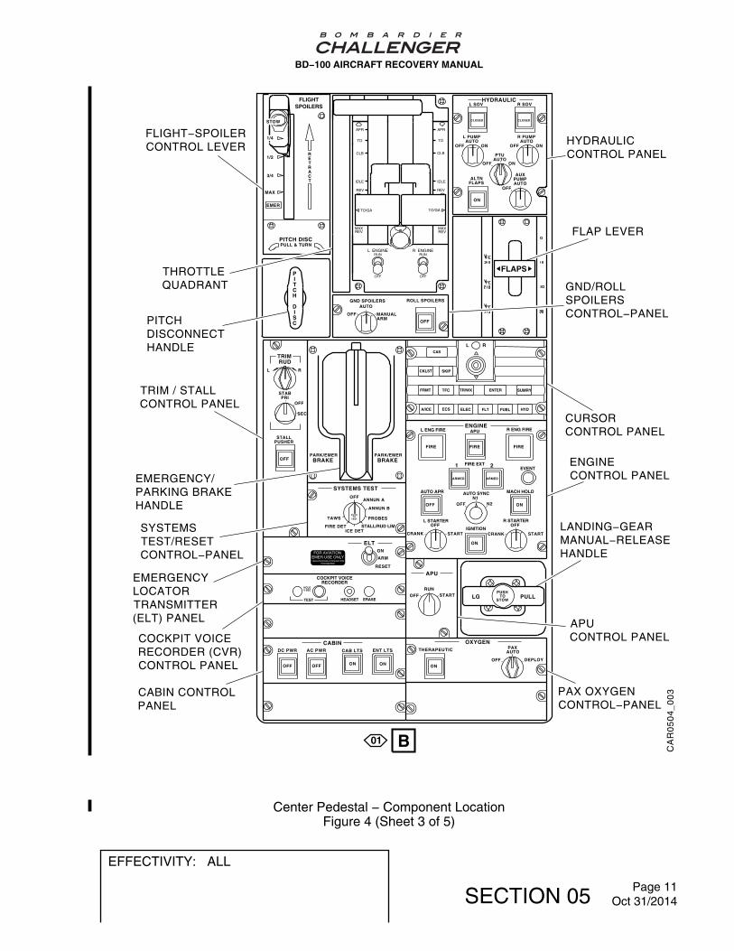
3. Engine/APU Fire Controls
On Challenger 300 A/C
A. The control and monitor panels are in the flight compartment. Refer to Figure 3and Figure 4.
On Challenger 350 A/C
B. The control and monitor panels are in the flight compartment. Refer to Figure 3and Figure 5.
C. To stop the engines do the following:
− On the Center Pedestal set the LEFT ENGINE RUN and/or RIGHT ENGINE RUNswitch to OFF.
− Push the LEFT ENG FIRE and/or RIGHT ENG FIRE pushbutton annunciator(s)(PBA) in the flight compartment panel. This shuts off the applicable engine fuel,hydraulics, electrical systems and bleed air.
D. To stop the APU:
− On the ground, the APU should stop automatically if a fire occurs. If it does not or ifyou need to manually stop the APU, do the following:
− On the Center Pedestal set the APU RUN switch to OFF.
− Push the APU FIRE PBA in the flight compartment panel. This shuts off the APU fueland electrical system.
BD−100 AIRCRAFT RECOVERY MANUAL
EFFECTIVITY: ALL
SECTION 05 Page 7Oct 31/2014

CA
R05
03_0
01
A
L ENG FIRE
ON
IGNITIONSTART CRANKCRANK
L STARTEROFF
OFFN1
N2
FIRE EXT
START
R STARTEROFF
EVENT
FIREFIREFIRE
ENGINEAPU FIRE R ENG FIRE
OFF
AUTO APR
ARMED
1
ARMED
2
ON
MACH HOLDAUTOSYNC
A
BD−100 AIRCRAFT RECOVERY MANUAL
Engines/APU Fire ControlsFigure 3
EFFECTIVITY: ALL
SECTION 05 Page 8Jul 11/2005

CA
R05
04_0
01
FUEL GRAVITY XFLOW
L PUMP AUTO
ON OFF OFF XFER
R PUMP AUTO
ON
ON
OFF OFF
OFF
ON
ON
CABIN MAN TEMP
RAM AIR
L BLEED X BLEED R BLEED
APU
AIR COND BLEED
COLD COLD HOT HOT
NORM PACK ONLY
TRIM AIR ONLY ON
ON
ON
DN UP
PRESSURIZATION MANUAL LNDG ALT
DITCHING EMER DEPRESS
MAN RATE
ON
ON
ON
OFF OFF
OFF OFF
OFF OFF
OFF OFF
ANTI−ICE
PROBES SOURCE WING
WSHLD/WINDOW
FROM L
FROM R
NORM L R
ENG L L R R
ON
ON
L ESS R ESS
L MAIN L AUX R AUX R MAIN
ELECTRICAL L BATT EXT PWR
BUS TIE
L GEN APU GEN R GEN
R BATT
AVAIL
TUNE RIGHT
DISPLAYS LEFT
DISPLAYS
ATT/HDG AIR DATA
NORM
NORM
NORM
NORM NORM
PFD REV
PFD REV
MFD REV
MFD REV
COM 1 121.50
CDU ONLY
1 1 2 2
OFF OFF OFF OFF
OFF OFF OFF OFF
L R A R M
T A X I
B E L T S
B C N
LIGHTING WING INSP NAV STROBE
SMKG/ BELTS
EMER LTS ON
LANDING N LDG/TAXI
COCKPIT
MAN FMS
ALT SOURCE SELECT
WING
OFF
INST STBY
MFD ONLY
AIR CONDITION / BLEEDCONTROL PANEL
EFFECTIVITY
A/C 20125 to 20500
01
02
03
A/C 20001 to 20124 Pre IFIS STCST01732LA−D or A/C 20003 to 20124Pre SB100−46−06
A/C 20001 to 20124 Post IFIS STCST01732LA−D or A/C 20003 to 20124Post SB100−46−06
FUEL CONTROLPANEL
ANTI−ICECONTROLPANEL
CONTROLDISPLAYUNIT(OPTIONAL)
REVERSIONSELECTPANEL
ELECTRICALCONTROLPANEL
LIGHTINGCONTROLPANEL
CONTROLDISPLAYUNIT
PRESSURIZATIONCONTROL PANEL
A
A
B
01
BD−100 AIRCRAFT RECOVERY MANUAL
Center Pedestal − Component LocationFigure 4 (Sheet 1 of 5)
EFFECTIVITY: ALL
SECTION 05 Page 9Oct 31/2014

CA
R05
04_0
02
AIR CONDITION / BLEEDCONTROL PANELFUEL CONTROL
PANEL
ANTI−ICECONTROLPANEL
CONTROLDISPLAYUNIT(OPTIONAL)
CURSORCONTROLPANEL
ELECTRICALCONTROLPANEL
CURSORCONTROLPANEL
CONTROLDISPLAYUNIT
PRESSURIZATIONCONTROL PANEL
FUEL GRAVITY XFLOW
L PUMP AUTO
ON OFF OFF XFER
R PUMP AUTO
ON
ON
OFF OFF
OFF
ON
ON
CABIN MAN TEMP
RAM AIR
L BLEED X BLEED R BLEED
APU
AIR COND BLEED
COLD COLD HOT HOT
NORM PACK ONLY
TRIM AIR ONLY ON
ON
ON
DN UP
PRESSURIZATION MANUAL LNDG ALT
DITCHING EMER DEPRESS
MAN RATE
ON
ON
ON
OFF OFF
OFF OFF
OFF OFF
OFF OFF
ANTI−ICE
PROBES SOURCE WING
WSHLD/WINDOW
FROM L
FROM R
NORM L R
ENG L L R R
ON
ON
L ESS R ESS
L MAIN L AUX R AUX R MAIN
ELECTRICAL L BATT EXT PWR
BUS TIE
L GEN APU GEN R GEN
R BATT
AVAIL
COCKPIT
MAN FMS
ALT SOURCE SELECT
WING
OFF
INST STBY
A02
03
CLR
UPRMENU ESC
LWRMENU
STAT
UPRFRMT CKLST SKIP
LWRFRMT TFC TR/WX
CAS ENTER
PUSH
S
EL E C
T
A/ICE ECS ELEC FLT
FUEL HYD SUMRY
MEM 1
MEM 2MENUADV
DATA
ZOOMMEM 3
CHART JSTK
− +
UPRMENU ESC
LWRMENU
STAT
UPRFRMT CKLST SKIP
LWRFRMT TFC TR/WX
CAS ENTER
PUSH
S
EL E C
T
A/ICE ECS ELEC FLT
FUEL HYD SUMRY
MEM 1
MEM 2MENUADV
DATA
ZOOMMEM 3
CHART JSTK
− +
BD−100 AIRCRAFT RECOVERY MANUAL
Center Pedestal − Component LocationFigure 4 (Sheet 2 of 5)
EFFECTIVITY: ALL
SECTION 05 Page 10Oct 31/2014
HYDRAULIC L SOV R SOV
L PUMP AUTO
OFF
PTU AUTO
R PUMP AUTO
ON OFF ON
OFF ON
AUX PUMP AUTO
ALTN FLAPS
CLOSED CLOSED
OFF
P I T C H
D I S C
GND SPOILERS AUTO
OFF MANUAL ARM
ROLL SPOILERS
OFF OFF
OFF
PARK/EMER BRAKE
PARK/EMER BRAKE
SYSTEMS TEST
TAWS
FIRE DET ICE DET
STALL/RUD LIM
PROBES
ANNUN B
ANNUN A OFF
PUSH TO
TEST
ELT
ARM
RESET
ON
ON ON
CABIN DC PWR CAB LTS ENT LTS AC PWR
ON
SUMRY ENTER TR/WX TFC FRMT
CKLST SKIP
CAS
A/ICE ECS ELEC FLT FUEL HYD
L R
TEST HEADSET ERASE
HOLD 5 SEC
COCKPIT VOICE RECORDER
FLAPS
OFF
L R
OFF
SEC
STALL PUSHER
STAB PRI
TRIM RUD
APR
TO
CLB
IDLE
REV
APR
TO
CLB
IDLE
REV
TO/GA
MAXREV
TO/GA
MAXREV
L ENGINE R ENGINERUN
OFF
RUN
OFF
ON
OXYGEN THERAPEUTIC AUTO
OFF DEPLOY
PAX
FIRE FIRE
ARMED
ON
ON
ARMED
OFF
CRANK START
OFF
OFF N2 N1
CRANK
OFF
START
L STARTER
IGNITION
AUTO SYNC MACH HOLD
EVENT FIRE EXT
AUTO APR
R STARTER
R ENG FIRE APU L ENG FIRE
1 2
ENGINE
APU
RUN
OFF START PUSH
TO STOW
LG PULL
FIRE
1/2
3/4
MAX
R E T R A C T
PULL & TURN PITCH DISC
EMER
FLIGHTSPOILERS
STOW
1/4
EMERGENCYLOCATORTRANSMITTER(ELT) PANEL
FLIGHT−SPOILERCONTROL LEVER
SYSTEMSTEST/RESETCONTROL−PANEL
EMERGENCY/PARKING BRAKEHANDLE
TRIM / STALLCONTROL PANEL
PITCHDISCONNECTHANDLE
GND/ROLLSPOILERSCONTROL−PANEL
LANDING−GEARMANUAL−RELEASEHANDLE
COCKPIT VOICERECORDER (CVR)CONTROL PANEL
CABIN CONTROLPANEL
PAX OXYGENCONTROL−PANEL
APUCONTROL PANEL
ENGINECONTROL PANEL
CURSORCONTROL PANEL
HYDRAULICCONTROL PANEL
THROTTLEQUADRANT
FLAP LEVER
B01
CA
R0
50
4_
00
3
BD−100 AIRCRAFT RECOVERY MANUAL
Center Pedestal − Component LocationFigure 4 (Sheet 3 of 5)
EFFECTIVITY: ALL
SECTION 05 Page 11Oct 31/2014

ON
OXYGEN THERAPEUTIC AUTO
OFF DEPLOY
PAX
FIRE FIRE
ARMED
ON
ON
ARMED
OFF
CRANK START
OFF
OFF N2 N1
CRANK
OFF
START
L STARTER
IGNITION
AUTO SYNC MACH HOLD
EVENT FIRE EXT
AUTO APR
R STARTER
R ENG FIRE APU L ENG FIRE
1 2
ENGINE
APU
RUN
OFF START PUSH
TO STOW
LG PULL
FIRE
HYDRAULIC L SOV R SOV
L PUMP AUTO
OFF
PTU AUTO
R PUMP AUTO
ON OFF ON
OFF ON
AUX PUMP AUTO
ALTN FLAPS
CLOSED CLOSED
OFF
P I T C H
D I S C
GND SPOILERS AUTO
OFF MANUAL ARM
ROLL SPOILERS
OFF
ON
FLAPS
APR
TO
CLB
IDLE
REV
APR
TO
CLB
IDLE
REV
TO/GA
MAXREV
TO/GA
MAXREV
L ENGINE R ENGINERUN
OFF
RUN
OFF
OFF OFF OFF OFF
OFF OFF OFF OFF
L R
A R M
T A X I
B E L T S
B C N
LIGHTING WING INSP NAV STROBE
SMKG/ BELTS
EMER LTS ON
LANDING N LDG/TAXI
TEST HEADSET ERASE
HOLD 5 SEC
COCKPIT VOICE RECORDER
TUNE
RIGHT DISPLAYS
LEFT DISPLAYS
ATT/HDG AIR DATA
NORM
NORM
NORM
NORM NORM
PFD REV
PFD REV
MFD REV
MFD REV
COM 1 121.50
CDU ONLY
1 1 2 2 MFD ONLY
EICASL MFD
R MFDBOTHPFDS
OFF OFF ON ON
CABIN DC PWR CAB LTS ENT LTS AC PWR
PARK/EMER BRAKE
PARK/EMER BRAKE
SYSTEMS TEST
TAWS
FIRE DET ICE DET
STALL/RUD LIM
PROBES
ANNUN B
ANNUN A OFF
PUSH TO
TEST
ELT
ARM
RESET
ON
OFF
L R
OFF
SEC
STALL PUSHER
STAB PRI
TRIM RUD
1/2
3/4
MAX
R E T R A C T
PULL & TURN PITCH DISC
EMER
FLIGHTSPOILERS
STOW
1/4
SYSTEMTEST/RESETCONTROL−PANEL
FLIGHT−SPOILERCONTROL LEVER
REVERSIONSELECTPANEL
EMERGENCY/PARKING BRAKEHANDLE
TRIM / STALLCONTROL PANEL
PITCHDISCONNECTHANDLE
GND/ROLLSPOILERSCONTROL−PANEL
LANDING−GEARMANUAL−RELEASEHANDLE
PAX OXYGENCONTROL−PANEL
APUCONTROL PANEL
ENGINECONTROL PANEL
LIGHTINGCONTROL PANEL
HYDRAULICCONTROL PANEL
THROTTLEQUADRANT
FLAP LEVER
CABIN CONTROLPANEL
COCKPIT VOICERECORDER (CVR)CONTROL PANEL
EMERGENCYLOCATORTRANSMITTER(ELT) PANEL
B
CA
R0
50
4_
00
4
02
BD−100 AIRCRAFT RECOVERY MANUAL
Center Pedestal − Component LocationFigure 4 (Sheet 4 of 5)
EFFECTIVITY: ALL
SECTION 05 Page 12Oct 31/2014

HYDRAULIC L SOV R SOV
L PUMP AUTO
OFF
PTU AUTO
R PUMP AUTO
ON OFF ON
OFF ON
AUX PUMP AUTO
ALTN FLAPS
CLOSED CLOSED
OFF
P I T C H
D I S C
GND SPOILERS AUTO
OFF MANUAL ARM
ROLL SPOILERS
OFF OFF
FIRE FIRE
ARMED
ON
ON
ARMED
OFF
OFF
PARK/EMER BRAKE
PARK/EMER BRAKE
SYSTEMS TEST
TAWS
FIRE DET ICE DET
STALL/RUD LIM
PROBES
ANNUN B
ANNUN A OFF
PUSH TO
TEST
CRANK START
OFF
OFF N2 N1
CRANK
OFF
START
L STARTER
IGNITION
AUTO SYNC MACH HOLD
EVENT FIRE EXT
AUTO APR
R STARTER
R ENG FIRE APU L ENG FIRE
1 2
ENGINE
ON ON
CABIN DC PWR CAB LTS ENT LTS AC PWR
APU
RUN
OFF START PUSH
TO STOW
LG PULL
ON
FIRE
TEST HEADSET ERASE
HOLD 5 SEC
COCKPIT VOICE RECORDER
FLAPS
1/2
3/4
MAX
R E T R A C T
PULL & TURN PITCH DISC
EMER
FLIGHTSPOILERS
OFF
L R
OFF
SEC
STALL PUSHER
STAB PRI
TRIM RUD
APR
TO
CLB
IDLE
REV
APR
TO
CLB
IDLE
REV
TO/GA
MAXREV
TO/GA
MAXREV
L ENGINE R ENGINERUN
OFF
RUN
OFF
OFF OFF OFF OFF
OFF OFF OFF OFF
L R
A R M
T A X I
B E L T S
B C N
LIGHTING WING INSP NAV STROBE
SMKG/ BELTS
EMER LTS ON
LANDING N LDG/TAXI
TUNE
RIGHT DISPLAYS
LEFT DISPLAYS
ATT/HDG AIR DATA
NORM
NORM
NORM
NORM NORM
PFD REV
PFD REV
MFD REV
MFD REV
COM 1 121.50
CDU ONLY
1 1 2 2 MFD ONLY
ELT
ARM
RESET
ON
EICASL MFD
R MFDBOTHPFDS
SYSTEMTEST/RESETCONTROL−PANEL
FLIGHT−SPOILERCONTROL LEVER
REVERSIONSELECTPANEL
EMERGENCY/PARKING BRAKEHANDLE
TRIM / STALLCONTROL PANEL
PITCHDISCONNECTHANDLE
GND/ROLLSPOILERSCONTROL−PANEL
LANDING−GEARMANUAL−RELEASEHANDLE
PAX OXYGENCONTROL−PANEL
APUCONTROL PANEL
ENGINECONTROL PANEL
LIGHTINGCONTROL PANEL
HYDRAULICCONTROL PANEL
THROTTLEQUADRANT
FLAP LEVER
CABIN CONTROLPANEL
COCKPIT VOICERECORDER (CVR)CONTROL PANEL
EMERGENCYLOCATORTRANSMITTER(ELT) PANEL
B03
CA
R0
50
4_
00
5
STOW
1/4
ON
OXYGEN THERAPEUTIC AUTO
OFF DEPLOY
PAX
BD−100 AIRCRAFT RECOVERY MANUAL
Center Pedestal − Component LocationFigure 4 (Sheet 5 of 5)
EFFECTIVITY: ALL
SECTION 05 Page 13Oct 31/2014

A
B
FUEL GRAVITY XFLOW
L PUMP AUTO
ON OFF OFF XFER
R PUMP AUTO
ON
ON
OFF OFF
OFF
ON
ON
CABIN MAN TEMP
RAM AIR
L BLEED X BLEED R BLEED
APU
AIR COND BLEED
COLD COLD HOT HOT
NORM PACK ONLY
TRIM AIR ONLY ON
ON
ON
DN UP
PRESSURIZATION MANUAL LNDG ALT
DITCHING EMER DEPRESS
MAN RATE
ON
ON
ON
OFF OFF
OFF OFF
OFF OFF
OFF OFF
ANTI−ICE
PROBES SOURCE WING
WSHLD/WINDOW
FROM L
FROM R
NORM L R
ENG L L R R
ON
ON
L ESS R ESS
L MAIN L AUX R AUX R MAIN
ELECTRICAL L BATT EXT PWR
BUS TIE
L GEN APU GEN R GEN
R BATT
AVAIL
COCKPIT
MAN FMS
ALT SOURCE SELECT
WING
OFF
INST STBY
A
CLR
UPRMENU ESC
LWRMENU
STAT
UPRFRMT CKLST SKIP
LWRFRMT TFC TR/WX
CAS ENTER
PUSH
S
EL E C
T
A/ICE ECS ELEC FLT
FUEL HYD SUMRY
MEM 1
MEM 2MENUADV
DATA
ZOOMMEM 3
CHART JSTK
− +
UPRMENU ESC
LWRMENU
STAT
UPRFRMT CKLST SKIP
LWRFRMT TFC TR/WX
CAS ENTER
PUSH
S
EL E C
T
A/ICE ECS ELEC FLT
FUEL HYD SUMRY
MEM 1
MEM 2MENUADV
DATA
ZOOMMEM 3
CHART JSTK
− +
AIR CONDITION / BLEEDCONTROL PANELFUEL CONTROL
PANEL
ANTI−ICECONTROLPANEL
CONTROLDISPLAYUNIT(OPTIONAL)
CURSORCONTROLPANEL
ELECTRICALCONTROLPANEL
CURSORCONTROLPANEL
CONTROLDISPLAYUNIT
PRESSURIZATIONCONTROL PANEL
BA
R0
50
4_
00
1
BD−100 AIRCRAFT RECOVERY MANUAL
Center Pedestal − Component LocationFigure 5 (Sheet 1 of 2)
EFFECTIVITY: ALL
SECTION 05 Page 14Oct 31/2014

HYDRAULIC L SOV R SOV
L PUMP AUTO
OFF
PTU AUTO
R PUMP AUTO
ON OFF ON
OFF ON
AUX PUMP AUTO
ALTN FLAPS
CLOSED CLOSED
OFF
P I T C H
D I S C
GND SPOILERS AUTO
OFF MANUAL ARM
ROLL SPOILERS
OFF OFF
FIRE FIRE
ARMED
ON
ON
ARMED
OFF
OFF
PARK/EMER BRAKE
PARK/EMER BRAKE
SYSTEMS TEST
TAWS
FIRE DET ICE DET
STALL/RUD LIM
PROBES
ANNUN B
ANNUN A OFF
PUSH TO
TEST
CRANK START
OFF
OFF N2 N1
CRANK
OFF
START
L STARTER
IGNITION
AUTO SYNC MACH HOLD
EVENT FIRE EXT
AUTO APR
R STARTER
R ENG FIRE APU L ENG FIRE
1 2
ENGINE
ON ON
CABIN DC PWR CAB LTS ENT LTS AC PWR
APU
RUN
OFF START PUSH
TO STOW
LG PULL
ON
FIRE
TEST HEADSET ERASE
HOLD 5 SEC
COCKPIT VOICE RECORDER
FLAPS
1/2
3/4
MAX
R E T R A C T
PULL & TURN PITCH DISC
EMER
FLIGHTSPOILERS
OFF
L R
OFF
SEC
STALL PUSHER
STAB PRI
TRIM RUD
APR
TO
CLB
IDLE
REV
APR
TO
CLB
IDLE
REV
TO/GA
MAXREV
TO/GA
MAXREV
L ENGINE R ENGINERUN
OFF
RUN
OFF
OFF OFF OFF OFF
OFF OFF OFF OFF
L R
A R M
T A X I
B E L T S
B C N
LIGHTING WING INSP NAV STROBE
SMKG/ BELTS
EMER LTS ON
LANDING N LDG/TAXI
TUNE
RIGHT DISPLAYS
LEFT DISPLAYS
ATT/HDG AIR DATA
NORM
NORM
NORM
NORM NORM
PFD REV
PFD REV
MFD REV
MFD REV
COM 1 121.50
CDU ONLY
1 1 2 2 MFD ONLY
ELT
ARM
RESET
ON
EICASL MFD
R MFDBOTHPFDS
B
BA
R0
50
4_
00
2
STOW
1/4
ON
OXYGEN THERAPEUTIC AUTO
OFF DEPLOY
PAX
SYSTEMTEST/RESETCONTROL−PANEL
FLIGHT−SPOILERCONTROL LEVER
REVERSIONSELECTPANEL
EMERGENCY/PARKING BRAKEHANDLE
TRIM / STALLCONTROL PANEL
PITCHDISCONNECTHANDLE
GND/ROLLSPOILERSCONTROL−PANEL
LANDING−GEARMANUAL−RELEASEHANDLE
PAX OXYGENCONTROL−PANEL
APUCONTROL PANEL
ENGINECONTROL PANEL
LIGHTINGCONTROL PANEL
HYDRAULICCONTROL PANEL
THROTTLEQUADRANT
FLAP LEVER
CABIN CONTROLPANEL
COCKPIT VOICERECORDER (CVR)CONTROL PANEL
EMERGENCYLOCATORTRANSMITTER(ELT) PANEL
BD−100 AIRCRAFT RECOVERY MANUAL
Center Pedestal − Component LocationFigure 5 (Sheet 2 of 2)
EFFECTIVITY: ALL
SECTION 05 Page 15Oct 31/2014

4. Electrical Control Panels and Battery Locations
A. Refer to Figure 6 and Figure 12 for aircraft and Integrated Standby Instrument (ISI)battery locations.
B. To isolate electrical power do the following:
− If engines are running select the L GEN and/or R GEN switch(es) to OFF.
− Push the L BATTERY and/or R BATTERY PBA to OFF.
− Push the STBY INST battery PBA to OFF.
C. To disconnect main battery do the following:
− Open the aft compartment access door.
− Disconnect the battery power connector from the battery.
− Disconnect the electrical connector from the battery.
D. To disconnect Integrated Standby Instrument (ISI) battery:
− In the Nose Landing Gear Wheelwell, remove the access door 121ALZ. Refer toFigure 12.
− Disconnect the battery connector from the battery.
BD−100 AIRCRAFT RECOVERY MANUAL
EFFECTIVITY: ALL
SECTION 05 Page 16Oct 31/2014
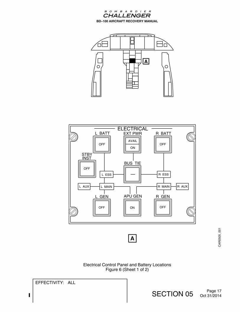
CA
R05
05_0
01
A
A
ELECTRICALL BATT R BATT
STBYINST
BUS TIE
L GEN R GEN
EXT PWR
APU GEN
OFFAVAIL
ONOFF
OFF
L AUX
L ESS
L MAIN
R ESS
R MAIN R AUX
OFF ON OFF
BD−100 AIRCRAFT RECOVERY MANUAL
Electrical Control Panel and Battery LocationsFigure 6 (Sheet 1 of 2)
EFFECTIVITY: ALL
SECTION 05 Page 17Oct 31/2014

CA
R05
05_0
02
B
B
BATTERIES
BD−100 AIRCRAFT RECOVERY MANUAL
Electrical Control Panel and Battery LocationsFigure 6 (Sheet 2 of 2)
EFFECTIVITY: ALL
SECTION 05 Page 18Oct 31/2014

5. Flammable Fluids and Gases
Table 2 lists all flammable fluids and gases carried on the aircraft. The table also gives thespecifications and the commercial grades and capacities. Refer to Figure 7 for locations ofthe reservoirs and tanks.
Table 2 − Flammable Fluids and Gases
CAPACITY Specification orCommercial Grades
CubicInches
U.SGallons
ImperialGallons
Liters Weight
FuelSystemTotalCapacity
— 2 096 1 745 7 934 14 150 lbs6 424 [email protected]/usg
ASTM D1655Jet AJet A−1Jet BJP− 4
Engine OilTanks
— Left: 1.26Right: 1.51
Left: 1.03Right: 1.19
Left: 4.7Right: 5.7
— MIL−PRF−23699Type 2Mobil Jet Engine Oil II
HydraulicReservoirs
RH−52.5LH−75AUX−15
2.273.250.65
— 8.6012.302.46
— CMS 564−03 Type IV
APU OilTanks
— 0.50 0.42 1.9 — MIL−PRF−23699Type 2Mobil Jet Engine Oil II
OxygenBottleSystemPressure1850 PSI
Basic:77 FT³option:115 FT³
— — Basic: 2 180option: 3 256
— Therapeutic OxygenMIL−PRF−27210Type 1
BD−100 AIRCRAFT RECOVERY MANUAL
EFFECTIVITY: ALL
SECTION 05 Page 19Oct 31/2014
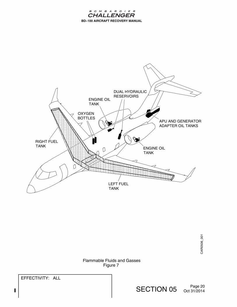
APU AND GENERATORADAPTER OIL TANKS
LEFT FUELTANK
RIGHT FUELTANK
OXYGENBOTTLES
DUAL HYDRAULICRESERVOIRS
ENGINE OILTANK
ENGINE OILTANK
CA
R05
06_0
01
BD−100 AIRCRAFT RECOVERY MANUAL
Flammable Fluids and GassesFigure 7
EFFECTIVITY: ALL
SECTION 05 Page 20Oct 31/2014

6. Fuel System General Layout
A. The wing fuel is contained in a wet wing−box structure. The structure is divided in twowing tanks at the wing center line. The fuel is contained between the front and the rearspars in the left and the right tanks., Refer to Figure 8.
B. Feed/collector tanks are integrally contained within each tank. Baffles in each wing tankrestrict fuel sloshing thus limiting center of gravity shifts with changes in aircraft attitude.Swing check valves on the baffles allow fuel flow in the inboard direction only. Flush,self−closing dual seal water drain valves are located at all the low points of the system.
C. Refer to Figure 9 for the fuel system indication in the flight compartment, .
BD−100 AIRCRAFT RECOVERY MANUAL
EFFECTIVITY: ALL
SECTION 05 Page 21Oct 31/2014

GRAVITY FILLER CAP
PRESSURE REFUEL/DEFUEL ADAPTOR
WATER DRAIN VALVE
A
B
C
CA
R05
07_0
71
RIGHTMAIN TANK
A
A
LEFTMAIN TANK
B
C
C
C
C
BD−100 AIRCRAFT RECOVERY MANUAL
Fuel System LayoutFigure 8
EFFECTIVITY: ALL
SECTION 05 Page 22Oct 31/2014

CA
R05
08_0
01
A
GRAVITYXFLOW
FUEL
XFER OFFAUTO
R PUMP
ONOFFAUTO
L PUMP
ON
A
B
BD−100 AIRCRAFT RECOVERY MANUAL
Fuel Controls in the Flight CompartmentFigure 9 (Sheet 1 of 2)
EFFECTIVITY: ALL
SECTION 05 Page 23Oct 31/2014

FIRE
600 600
93.0 61.0NI
MACHHOLD
VIB VIB
ITT
IGN IGN
N2OIL PRESSOIL TEMPFF PPH
84.7461157300
84.7461157300
APU RPM 300250APU EGT
FUEL QTY LBSTOTAL 12000
6000 6000
START
START
STAB AIL
LWD RWDRUD
L R
NU
ND
6.6
FLAPS 0 GEAR
SPOLIERS
CAB ALTCAB RATE
73001000
PARKING BRAKEBRAKE OVERHEATGEAR DISAGREEFUEL IMBALANCEDISPLAY COOL
FUEL
CONTROL
COM1 NAV1 ATC1/TCAS ADF1 HF1 COM3 COM2
118.000 108.00 1200 1799.5 118.000 118.000118.000 118.0002.0000190.0108.00118.000 STBY
ABV
TX
UP
O
DN
2.0000 AM
1234567890123456789012345678901234567890
1234567890123456789012345678901234567890
1234567890123456789012345678901234567890
123456789012345678901234567890123456789012345678901234567890123456789012345678901234567890123456789012345678901234567890123456789012345678901234567890123456789012345678901234567890
PAGE 1/4
85.0 MCT 85.0 MCT TRIM LEFT ENGINE FIREV
T
FUEL USED3900 LBS
° C135° C135
° C43
4870 LBS4870 LBS
TOTAL FUEL9700 LBS
P P
25 25
APU
12345678901234567890
12345678901234567890
MFD CONTROLC
AR
0508
_002
B
BD−100 AIRCRAFT RECOVERY MANUAL
Fuel Controls in the Flight CompartmentFigure 9 (Sheet 2 of 2)
EFFECTIVITY: ALL
SECTION 05 Page 24Oct 31/2014

7. Emergency Break−In Zone
A. The emergency break−in−zone on the Challenger 300 is 16 in (406 mm) wide by 30 in(762 mm) long. The emergency break−in−zone is located between FS345.00 andFS375.00 and between LBL8.00 and RBL8.00. Refer to Figure 10.
8. Tires
A. If the wheels on the aircraft become hotter than usual (for example, because of hardbraking or under−inflation), there is a possibility that the fusible plugs can melt. This willrelease tire pressure quickly. It is important for persons not to approach the wheels fromthe sides. Refer to Figure 1.
9. Composite Material Fire Precautions
A. General
(1) With the new generation aircraft, composite materials are widely used. Thesematerials are made by bonding layers of fiber together in a "criss−cross" patternwith resins, epoxies and phenols. Refer to Figure 11 for the locations of thecomposite structures on the Bombardier Challenger 300.
B. Dangerous Effects of Free Fibers
(1) In the case of an aircraft fire, the bonding agents (resins, epoxies and phenols) canbecome unstable and break down. This releases dangerous gases into theatmosphere. Fire fighters and other personnel should avoid the downwind area ofthe fire, specially when they do not use self−contained breathing equipment. As wellas dangerous gases, the fire also releases small particles of free fibers.
BD−100 AIRCRAFT RECOVERY MANUAL
EFFECTIVITY: ALL
SECTION 05 Page 25Dec 22/2015

(2) When the fire is extinguished and the structure becomes cool, the bonding agentsstop the release of these free fibers. However, the hazards due to the release offree fibers continues and can become a long term problem. This is because:
− When The free fibers come in contact with fire, the fibers tend to break intoshorter lengths and smaller diameters. This makes them light and easilyairborne. The free fibers also absorb pyrolytic acid. This poisonous material ispicked up from the burned materials. The smoke from the fire can carry the freefibers and can therefore send the contamination over a large area.
− Without correct protection, personnel can breathe in the free fibers and they canbond to a person’s respiratory system. They can also move to other internalorgans and cause damage. The free fibers are very stable and there is nodeterioration of the fibers in the body.
− They will burn the eyes.
− The ends of the fibers are very sharp. This will let them pass through clothingand skin. If you rub the affected area, you can cause dermatitis which willrequire medical treatment.
C. Control of Free Fibers
(1) As soon as the fire fighting and medical activities are completed, take steps to limitthe spread of the free fibers. This is important when you move the damagedaircraft.
(2) Treat the components that can release free fibers as follows:
− Keep the materials wet with Aqueous Fire Fighting Foam (AFFF) or water. Withthe AFFF, wet the materials every six hours
NOTE: Light oil, clear liquid furniture wax, polyacrylic acid or strippable paint, areall good materials to contain free fibers. These liquids are not consideredto be a problem to future investigations.
− Move the damaged aircraft the minimum distance possible and keep it on pavedsurfaces when possible. This will make the removal of the contamination moreefficient.
(3) All personnel that work in the free fiber contaminated area must wear disposablepaper coveralls, heavy boots, thick leather gloves, goggles, and a dust mask. Theymust discard the paper coveralls and dust mask when they leave the contaminatedarea.
BD−100 AIRCRAFT RECOVERY MANUAL
EFFECTIVITY: ALL
SECTION 05 Page 26Oct 31/2014

CA
R05
_091
RBL8.00
BREAK−IN−ZONELOCATION
EMERGENCY
THROUGH WINDOWSDO NOT ATTEMPT TO CHOP
WARNING
LBL8.00
FS
34
5.0
0
FS
37
5.0
0
BD−100 AIRCRAFT RECOVERY MANUAL
Emergency Break−in−zoneFigure 10
EFFECTIVITY: ALL
SECTION 05 Page 27Dec 22/2015

ELEVATORS
HORIZONTALSTABILIZER
RUDDER
DORSALFAIRING
ENGINECOWLS
CABINFLOOR
VERTICALSTABILIZERLEADING EDGE
THRUST REVERSERPIVOT DOORSOUTER SKIN
FLAPS
GROUNDSPOILERS
MULTI−FUNCTIONSPOILERS
WINGLETS
RADOME
NOSE LANDINGGEAR DOORS
WHEELBINS
AILERON
BELLYFAIRINGS
KEVLAR
GRAPHITE
FIBERGLASS
LEGEND
V−STAB FORWARDBULLET FAIRINGLH AND RH FORWARDACCESS PANELS
V−STAB AFTBULLET FAIRING,AND AFT CONE
TAILCONE
(LEFT AND RIGHT)
AFTNLGDOOR
OVER−WINGFAIRINGS
HYBRID
CA
R0
5_
10
1
BIRDSTRIKEBARRIER
STAIRSFLAPFAIRINGS
BD−100 AIRCRAFT RECOVERY MANUAL
Composite MaterialsFigure 11
EFFECTIVITY: ALL
SECTION 05 Page 28Oct 31/2014

CA
R05
11_0
01
A
A
FS227.50
STANDBY INSTRUMENTBATTERY
COMPARTMENTACCESS PANEL
CAMLOCKS
BATTERY
121ALZ
BD−100 AIRCRAFT RECOVERY MANUAL
Standby Instrument BatteryFigure 12
EFFECTIVITY: ALL
SECTION 05 Page 29Oct 31/2014


GROUND SAFETY
1. Towing the Aircraft
A. General
(1) If the aircraft cannot be taxied, push or tow the aircraft to move it.
(2) To push or tow the aircraft, attach the towbar to the nose wheel axle with the lugson the towbar. Let the two vehicules control movement of the aircraft. If the aircraftis being pushed and you apply the aircraft brakes hard, this can cause the nosegear to come off the ground.
On Challenger 300 A/C
(3) Refer to Figure 1 and Figure 2 for the tow bar installation and turn radii.
On Challenger 350 A/C
(4) Refer to Figure 1 and Figure 3 for the tow bar installation and turn radii.
B. Towing the Aircraft with Bridle
Table 1 − Towing Equipment
Reference Designation
TBD Towing Bridle
23X−51−01 Headset with Microphone and Lead
23−00−02 Headset Extension Cord
(1) Installation of Towing Bridle
CAUTION: DO NOT INSTALL THE WIRE ROPE ASSEMBLIES ON TOP OF THEBRAKE LINES OR WIRING HARNESS. MAKE SURE THAT ONLY THELEATHER BINDING OF THE WIRE ROPE ASSEMBLIES TOUCHESTHE MAIN LANDING GEAR. IF YOU DO NOT OBEY THESEINSTRUCTIONS, YOU CAN CAUSE DAMAGE TO EQUIPMENT.
(a) Attach the rope assemblies around each main landing gear as follows:
1 To tow the aircraft forward, release the clamps that hold the brake lines tothe main beam. Put the wire rope assemblies behind the brake lines onthe main beam, then around the main beam. Refer to Figure 4.
BD−100 AIRCRAFT RECOVERY MANUAL
EFFECTIVITY: ALL
SECTION 06 Page 1Oct 31/2014

2 To tow the aircraft rearward, put the wire rope assemblies over the trailingarm link and below the axle of each MLG. Refer to Figure 4.
NOTE: Loosen or remove the retaining clips to put the wire ropeassembly between the MLG and the brake lines and the wireharness.
WARNING: MAKE SURE THAT THERE ARE NO KINKS IN THE WIREROPE ASSEMBLIES. KINKS CAN CAUSE THE WIRE ROPEASSEMBLIES TO BREAK. THIS CAN CAUSE INJURY TOPERSONS AND DAMAGE TO THE EQUIPMENT.
3 Tow the aircraft. Obey all the safety precautions (Refer to Paragraph D).
(2) Removal of Towing Bridle
(a) Disconnect the wire rope assemblies from the anchor shackles.
(b) Remove the wire rope assemblies from the MLG.
(c) Clean, lubricate, and put the towing bridle into storage.
C. Ground Lockpins
(1) Refer to Figure 5 and Figure 6 for landing gear ground lockpins installation.
BD−100 AIRCRAFT RECOVERY MANUAL
EFFECTIVITY: ALL
SECTION 06 Page 2Oct 31/2014

CA
R06
01_0
01
TOWBAR
UPPERTORQUELINK
LOWERTORQUELINK
TOWBAR
AXLEENGAGEMENTPIN
A
A
SHEAR PIN
BD−100 AIRCRAFT RECOVERY MANUAL
Equipment to Tow the AircraftFigure 1
EFFECTIVITY: ALL
SECTION 06 Page 3Jul 11/2005
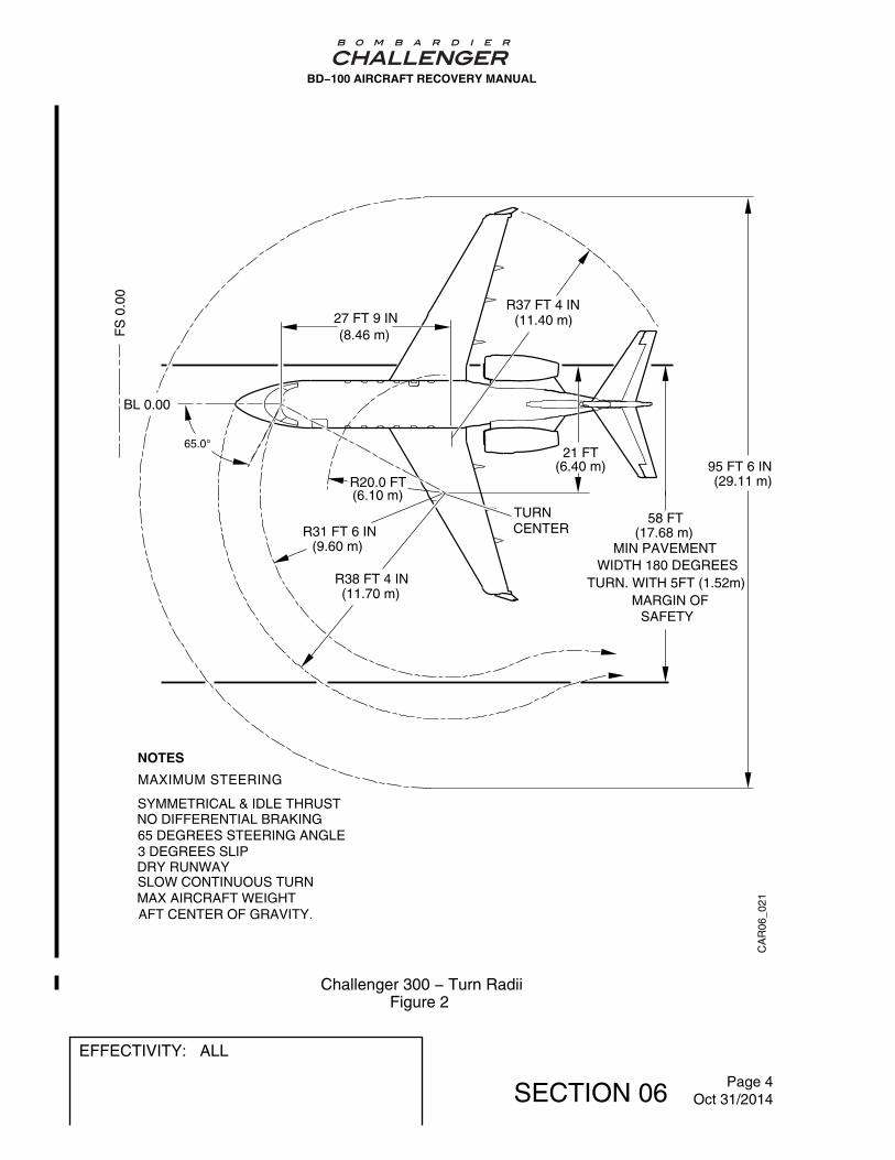
95 FT 6 IN
CA
R06
_021
58 FT
21 FT
R37 FT 4 IN27 FT 9 IN
R31 FT 6 IN
R38 FT 4 IN
R20.0 FT
65.0°
BL 0.00
FS
0.0
0
SYMMETRICAL & IDLE THRUSTNO DIFFERENTIAL BRAKING65 DEGREES STEERING ANGLE3 DEGREES SLIPDRY RUNWAYSLOW CONTINUOUS TURNMAX AIRCRAFT WEIGHTAFT CENTER OF GRAVITY.
MIN PAVEMENT WIDTH 180 DEGREES
TURN. WITH 5FT (1.52m)MARGIN OF
SAFETY
MAXIMUM STEERING
NOTES
(8.46 m)(11.40 m)
(6.10 m)
(9.60 m)
(11.70 m)
(6.40 m)
(17.68 m)
(29.11 m)
TURNCENTER
BD−100 AIRCRAFT RECOVERY MANUAL
Challenger 300 − Turn RadiiFigure 2
EFFECTIVITY: ALL
SECTION 06 Page 4Oct 31/2014

53 ft (16.15 m) MINIMUMPAVEMENT WIDTH180 DEGREES TURN
BA
R0
6_
00
1
Maximum steeringSymmetrical and idle thrustNo differential braking65 Degrees steering angle3 Degrees slipDry runwaySlow continuous turnMaximum aircraft weightAft center of gravity.
NOTES
62 DEGREES
BL 0.00
FS
0.0
0
R 20 ft(6.10 m)
R 38 ft 5 in(11.70 m)
101 ft 1 in(30.82 m)
21 ft(6.40 m)
R 31 ft 6 in(9.60 m)
R 37 ft 5 in(11.40 m)27 ft 10 in
(8.47 m)
TURNCENTER
MARGIN OF SAFETYWITH 5 ft (1.52 m)
BD−100 AIRCRAFT RECOVERY MANUAL
Challenger 350 − Turn RadiiFigure 3
EFFECTIVITY: ALL
SECTION 06 Page 5Oct 31/2014

CA
R06
_031
LEATHERBINDING
ANCHORSHACKLE
WIRE ROPEASSEMBLY
LEATHERBINDING
WIRE ROPEASSEMBLY
TRAILINGARM LINK
TOWING AIRCRAFT FORWARD
TOWING AIRCRAFT REARWARD
WARNING
CAUTION
BEFORE THE AIRCRAFT IS TOWED, MAKE SURE THAT ALL THE BOLTS AND PINS ARE ATTACHED SAFELY. ALSO MAKE SURE THAT THERE ARE NO KINKS IN THE WIRE ROPE ASSEMBLIES. YOU CAN CAUSEINJURIES TO PERSONS AND DAMAGE TO EQUIPMENT.
MAKE SURE THAT THE WIRE ROPE ASSEMBLIES DO NOT TOUCH THE BRAKE LINES OR THE WIRINGHARNESSES. ALSO MAKE SURE THAT ONLY THE LEATHER BINDINGS OF THE WIRE ROPE ASSEMBLIES TOUCH THE LANDING GEAR. YOU CAN CAUSE DAMAGE TO THE BRAKE LINES, THE WIRING HARNESSES, OR THE LANDING GEAR.
LEATHERBINDING
ANCHORSHACKLE
MAIN BEAM
A
A
B
B
BD−100 AIRCRAFT RECOVERY MANUAL
Towing by MLGFigure 4
EFFECTIVITY: ALL
SECTION 06 Page 6Oct 31/2014

CA
R06
_041
A
A
GROUNDLOCKING PIN
BD−100 AIRCRAFT RECOVERY MANUAL
Main Landing−Gear (MLG) LockpinFigure 5
EFFECTIVITY: ALL
SECTION 06 Page 7Oct 31/2014

CA
R06
_051
A
A
GROUNDLOCKING PIN
BD−100 AIRCRAFT RECOVERY MANUAL
Nose Landing−Gear (NLG) LockpinFigure 6
EFFECTIVITY: ALL
SECTION 06 Page 8Oct 31/2014

D. Safety Precautions
CAUTION: WHEN YOU TOW THE AIRCRAFT, OBEY THE PRECAUTIONS THATFOLLOW:
- OBEY ALL LOCAL AIRPORT REGULATIONS.
- APPLY TOWBAR LOADS SLOWLY AND CAREFULLY.
- MAKE ALL CHANGES TO THE SPEED OR THE DIRECTION SLOWLY.
- KEEP THE TURNS AS LARGE AS POSSIBLE.
- DO NOT USE THE AIRCRAFT BRAKES TO STOP THE AIRCRAFTUNLESS THERE IS AN EMERGENCY.
- DO NOT TOW THE AIRCRAFT IN A FORWARD DIRECTION AT MORETHAN 5 MPH (8 KM/H).
- DO NOT MOVE THE AIRCRAFT REARWARD AT MORE THAN 3 MPH (5KM/H).
- MAKE SURE THAT YOU PUT THE NOSEWHEEL IN THE CENTERPOSITION BEFORE THE AIRCRAFT IS PARKED.
IF YOU DO NOT OBEY THESE PRECAUTIONS, DAMAGE TO THEEQUIPMENT CAN OCCUR.
(1) Make sure that the tires are correctly inflated, if possible.
(2) Make sure that lockpins are installed in the NLG and MLG. Refer to Figure 5and Figure 6.
(3) Remove all items from around the aircraft, such as ground equipment, that canprevent the movement of the aircraft.
(4) Make sure that the nosewheel steering is turned off.
CAUTION: BEFORE YOU TOW THE AIRCRAFT, MAKE SURE THAT THERE IS AMINIMUM LOAD OF 1 050 LB (476.2 KG) ON THE NOSEWHEEL. IFYOU DO NOT DO THIS, YOU CAN CAUSE DAMAGE TO THEAIRCRAFT.
(5) A minimum load of 1000 lbs (454 kg) is necessary on the nose wheel before youtow the aircraft. Refer to the Bombardier Challenger Series aircraft Weight andBalance Manual to determine the load on the nose wheel. Add the applicableballast as necessary.
(6) Make sure that the landing gear selector−handle is set to the DN position.
(7) Put a qualified technician in the flight compartment to monitor the brake systempressure and operate the aircraft brakes.
BD−100 AIRCRAFT RECOVERY MANUAL
EFFECTIVITY: ALL
SECTION 06 Page 9Oct 31/2014

WARNING: WHEN YOU PREPARE THE AIRCRAFT FOR TOWING, OBEY THEPRECAUTIONS THAT FOLLOW:
- MAKE SURE THAT THE NOSEWHEEL STEERING IS SET TO THEOFF POSITION.
- MAKE SURE THAT THE NOSEWHEEL IS IN THE CENTERPOSITION.
- MAKE SURE THAT THE EXTERNAL SERVICING EQUIPMENT ISDISCONNECTED.
- MAKE SURE THAT ALL EXTERNAL DOORS AND PANELS ARECLOSED AND LATCHED.
IF YOU DO NOT OBEY THESE PRECAUTIONS, INJURY TO PERSONSAND DAMAGE TO EQUIPMENT CAN OCCUR.
(8) If possible, put the Battery Master switch to ON.
(9) Connect the intercom system between the driver of the tow vehicule and thetechnician in the flight compartment.
(10) In an area that has little space, have a person at each wingtip to make sure ofsufficient clearance from objects and the aircraft.
(11) Before you move the aircraft rearward, have a person at the tail to make sure ofsufficient clearance from objects and the aircraft.
(12) Remove the chocks and release the parking brake.
(13) Tow the aircraft not more than 5 MPH (8 KM/H) or push the aircraft not more than3 MPH (5 KM/H).
(14) After the tow operation, make sure the nose wheels are put to the center position.Do the operations that follow:
(a) Apply the parking brake.
(b) Chock the wheels.
(c) Release the parking brake.
(d) Disconnect the tow vehicule.
(e) Remove the tow bar or the towing bridle and park the aircraft.
NOTE: In some cases, after a tow operation there is a difference betweenthe MLG strut heights. A qualified technician can make sure theservicing of the struts is correct.
BD−100 AIRCRAFT RECOVERY MANUAL
EFFECTIVITY: ALL
SECTION 06 Page 10Oct 31/2014