airwave 8.2.1 release notes
TRANSCRIPT

AirWave 8.2.1
Release
Notes

Copyright Information
© Copyright 2016 Hewlett Packard Enterprise Development LP
Open Source Code
This product includes code licensed under the GNU General Public License, the GNU Lesser General PublicLicense, and/or certain other open source licenses. A complete machine-readable copy of the source codecorresponding to such code is available upon request. This offer is valid to anyone in receipt of this informationand shall expire three years following the date of the final distribution of this product version by Hewlett-Packard Enterprise Company. To obtain such source code, send a check or money order in the amount of US$10.00 to:
Hewlett-Packard Enterprise CompanyAttn: General Counsel3000 Hanover StreetPalo Alto, CA 94304USA
Please specify the product and version for which you are requesting source code. You may also request a copy ofthis source code free of charge at [email protected].
2 AirWave 8.2.1 | Release Notes

AirWave 8.2.1 | Release Notes Release Overview | 3
Chapter 2Release Overview
AirWave 8.2.1 is a software patch release that introduces fixes to issues detected in previous releases. For moreinformation about the features described in the following sections, see the AirWave 8.2 User Guide, Aruba 8.2Supported Infrastructure Devices document, and the Aruba Instant in AirWave 8.2 Deployment Guide.
Release Overviewl "New Features" on page 4 describes the new features introduced this release.
l "Features introduced in Previous Releases" on page 11 describes features introduced in previous releases ofAirWave 8.2.
l "Supported Infrastructure Devices" on page 38 lists new devices and Instant devices supported by AirWave8.2.x.
l "Resolved Issues" on page 40 describes issues resolved in AirWave 8.2.1 and previous releases.
l "Known Issues" on page 46 lists and describes the known issues identified in AirWave 8.2.1 and previousreleases.
Contacting Support
Main Site arubanetworks.com
Support Site support.arubanetworks.com
Airheads Social Forums and KnowledgeBase
community.arubanetworks.com
North American Telephone 1-800-943-4526 (Toll Free)
1-408-754-1200
International Telephone arubanetworks.com/support-services/contact-support/
Software Licensing Site licensing.arubanetworks.com
End-of-life Information arubanetworks.com/support-services/end-of-life/
Security Incident Response Team (SIRT) Site: arubanetworks.com/support-services/security-bulletins/
Email: [email protected]
Table 1: Contact Information

AirWave 8.2.1 | Release Notes New Features | 4
Chapter 3New Features
AirWave 8.2.1 introduces the following features and enhancements:
l "Support for New Devices" on page 4
l "Enhanced Support for Aruba Instant" on page 4
l "Refresh Option for VisualRF Heatmaps" on page 4
l "Enhanced Support Connection" on page 4
l "Enhanced HPE Aruba Switch Configuration" on page 5
Support for New DevicesAirWave supports several new Aruba devices. For more information, see "Support for New Devices in AirWave8.2.1" on page 38.
Enhanced Support for Aruba InstantAirWave supports template configuration for Instant 6.4.4.4-4.2.4.0.
Refresh Option for VisualRF HeatmapsThe toolbar on theVisualRF > Floorplan page displays a refresh button ( ) for regenerating and updating afloorplan heatmap. When you place a new AP on a floorplan, or add, delete or edit a wall, you can displayupdated heatmap information for that floorplan by clicking the refresh button. If you do not manually refreshthe floorplan, the floorplan will still automatically update after one hour.
Enhanced Support ConnectionA support connection is a point-to-point IP tunnel that is initiated from a AirWave server to Aruba's supportserver. AirWave 8.2.1 introduces changes to the process to launch a support connection, as well as securityenhancements for the connection tunnel.
When you open a case with technical support, AirWave technical support sends you an email with instructionsfor downloading and installing a .tar file used to launch the support connection. You must contact Arubatechnical support and provide login credentials before Aruba support staff can access your AirWave server.
Once the .tar file has been installed you can start, stop, or check the status of the support connection with thefollowing commands:
l # service support_connection start [<days>]
l # service support_connection restart [<days>]
l # service support_connection stop
l # service support_connection status
By default, the support connection remains open for fourteen days unless it is stopped with the# servicesupport_connection stop command. To start or restart a connection that does not expire, specify 0 for theoptional <days> parameter.

5 | New Features AirWave 8.2.1 | Release Notes
Enhanced HPE Aruba Switch ConfigurationAirWave introduces a partial configuration option that allows you to push full template configurations, while alsoallowing you to send partial configurations to HPE Aruba switches. This feature is supported on HPE Arubaswitches running firmware version 16.x or greater:
l 2620
l 2920
l 3800
l 3810
l 5400R
l 2530 YA
l 2530 YB
l 2930F
Enabling Partial ConfigurationThe default template configuration setting for a group of HPE Aruba switches pushes a full configuration to HPEAruba switches in that group. Therefore, by default, when you select a group in theGroups > List page andthen select Groups > Templates, the AirWave WebUI displays only the Full Config tab.
Figure 1: Full Template Configuration
Use the following procedure to enable the partial configuration feature:
1. Navigate to Groups > List and select the group.
2. Navigate to Groups > Basic.
3. Scroll down to theHPE Aruba Switch Config section.
4. Click the Template Config drop-down list and select Partial Config.
5. There are two options you can select that indicate whether to push a full configuration template to Zero-Touch Provisioning (ZTP) devices before AirWave applies additional partial configuration changes.
l Yes: If the group contains factory-default devices added to AirWave via ZTP, select Factory DefaultDevices Only from the Push complete configuration file drop-down list. This option requires that theZTP devices reboot after the full configuration update.
l No: Select this option to push a partial configuration to only HPE Aruba switches in the group. This optionis not recommended for groups that contain factory-default devices.

Figure 2: Enable Partial Template Configuration
6. Click Save and Apply, then click Apply Changes Now to save your settings. The AirWave WebUI displaysthe Partial Config tab on theGroups >Templates page for the selected group.
l If you selected Yes in Step 5, theGroups > Templates page displays both the Full Config tab (forpushing full configurations to factory-default devices) and the Partial Config tab (for pushing partialconfigurations to configured devices in the group.)
l If you selected No in Step 5, theGroups > Templates page displays the Partial Config tab only.
Figure 3: Partial Template Configuration
Creating a Partial Configuration JobTo create a new partial configuration job:
1. From theGroups > Templates page click the + icon at the top of theConfig Jobs table. The Config Jobswizard opens.
2. In theConfig Command tab, enter a name and (optionally) a description of the configuration job, then pastein a snippet of configuration or action commands. Click Next to continue to the next step in the wizard.
3. In the Select Device tab, click the checkmark to the left of any device name to select the devices to whichyou want to push the partial configuration setting. Click any of the column headings to sort the table by thatcolumn criteria, or enter a text string into any of the column heading fields to filter the table by that string.You can select one or more individual devices, or click the check mark in the upper left corner of the table toselect all devices in the table. Click Next to continue to the next step in the wizard.
4. Use the Schedule tab to select when the job will run. TheRun Now option is selected by default. Toschedule the job for another time, uncheck theRun Now checkbox, and click inside the Schedule Job field. Acalendar appears, allowing you to select a run date. You can also manually edit a schedule date and time byentering a schedule time in YYYY/MM/DD HH:MM format.
AirWave 8.2.1 | Release Notes New Features | 6

7 | New Features AirWave 8.2.1 | Release Notes
5. TheConfirm tab displays details for your configuration job. Click Confirm to save these settings, or clickBack to return to a previous page of the Wizard.
If a group is configured to use Partial Configuration mode, theManagement Mode option on theAPs/Devices > Manage page is hidden for non-ZTP devices in the group.
Viewing, Reverting, or Deleting Partial Configuration JobsYou can view information about partial configuration jobs and revert or delete them from theConfig Jobs andJob Details tables on theGroups > Templates > Partial Configuration page.
Figure 4: Config Jobs and Job Details tables.
TheConfig Jobs table displays the following information for the partial configuration jobs created for that groupof HPE Aruba switches. Click any of the column headings to sort the table by that column criteria, or enter a textstring into any of the column heading fields to filter the table by that string. You can also change the order inwhich the information is displayed in the table by selecting any column heading and dragging that column to anew position within the table.
Column Description
Name Name of the configuration job.
Description Description of the configuration job.
Status The partial configuration job can be in several states.
l Scheduled: The partial configuration job will run in the future.l Failed: The partial configuration job failed to run on one or more devices.l Success: The partial configuration job completed successfully on all devices.l Pending: The job has been scheduled, but the configuration changes have not been
pushed to all selected devices.l In Progress: The job started and configuration changes are in progress but are
incomplete.NOTE: Hover your mouse over the Status column to view detailed status informationfor all devices selected to receive the partial configuration update.
User Username of the user who created the partial configuration job.
Creation Time Timestamp showing the date and time of the partial configuration job creation.
Start Time Timestamp showing the date and time the partial configuration job started.
Table 2: Config Jobs Table Information

Column Description
End Time Time of partial configuration job completion for all devices
Action Click the Delete icon in this column to delete a partial configuration job.
Table 2: Config Jobs Table Information (Continued)
Viewing Job Information
To view additional information about a job:
1. Click a checkbox at the left side of theConfig Jobs table to select a specific configuration job.
2. Click theConfig Details tab to view the job name, description and configuration.
Viewing Device Information
To view information about the devices to which a partial configuration is pushed:
1. Select a configuration job in theConfig Jobs table.
2. Click theDevices tab to display theDevices table. TheDevices table displays the following information forselected partial configuration jobs.
3. Click any of the column headings to sort the table by that column criteria, or enter a text string into any of thecolumn heading fields to filter the table by that string. You can also change the order in which the informationis displayed in the table by selecting any column heading and dragging that column to a new position withinthe table.
Column Description
Device Name of the device to which the partial configuration job is pushed.
Status Shows whether the device is up or down.
IP Address IP address of the device.
Config Status Current status of the device configuration job:
l Failed: At least one command failed in the configuration snippet push for thedevice.
l Skipped: The device was down, so the configuration snippet push has been skippedfor the device.
l Success: All the commands in the configuration snippet push to the device wassuccessful.
l Reverted: After a configuration snippet failed to be pushed to the device, it wassuccessfully reverted to its previous configuration by receiving a full configurationpush and rebooting.
l Reverting: The device is in the process of reverting to its previous configurationafter a config snippet push failure.
l Pending: The configuration snippet push has been scheduled to start, but theconfiguration changes have not yet been pushed to the device.
l In Progress: The configuration snippet push has started, and configuration changesare in progress but are not yet completed.
NOTE: Hover your mouse over the Config Status column to view the amount of time ittook for that configuration job to run on the device.
Device Name of the device to which the partial configuration is pushed.
Start Time Timestamp showing the date and time the configuration job was started.
Table 3: Devices Table Information
AirWave 8.2.1 | Release Notes New Features | 8

9 | New Features AirWave 8.2.1 | Release Notes
Column Description
End Time Timestamp showing the date and time the configuration job was completed for thatdevice.
Type Shows the device type . For example, HPE Aruba 2920-24G-PoE+.
Action Select any of the icon links to view additional information:
l Telnet Log : View a log of telnet commands pushed by the partial configurationjob. This action is only available for partial configuration snippets that contain action(and not configuration) commands.
l Show Diff : Display the previous and current configurations in two side-by-sidewindows, with the differences between these two configurations highlighted. Thisaction is only available for partial configuration snippets that contain configuration(and not action) commands.
l Config Log : View a log of configuration commands pushed by the partialconfiguration job. This action is only available for partial configuration snippets thatcontain configuration (and not action) commands.
Table 3: Devices Table Information (Continued)
Reverting or Deleting Partial Configuration Jobs
To revert partial configuration jobs that failed or delete job details you don't want to keep:
1. Select the partial configuration job from theConfig Jobs table.
2. Click Revert in theAction column if you want to reset the device to its previous configuration. Or you canclick Delete and remove the job details.
Audit in AirWave for Partial ConfigThe Audit tab appears in the AirWave WebUI under the following conditions:
l TheAudit Tab appears only for devices in the group configured via Zero-Touch Provisioning (ZTP) with adevice state as “Factory”, when the template configuration mode is set to Partial Config, and theConfigurefactory devices with full config template option is set to Yes.
l TheAudit Tab does not appear for any devices in the group if the template configuration mode is set toPartial Config, and theConfigure factory devices with full config template option is set to No.
l TheAudit Tab appears for all devices in the group if the template configuration mode is set to Full Config.
Configuration CaveatsA partial configuration snippet supports either action commands (executed in enable mode) or configcommands (executed in config) mode. Partial configuration does not allow you to send both action and configcommands in a single configuration snippet.
Any partial configuration snippet that contains an action command is automatically run in enable mode,causingconfiguration commands in that snippet to fail.
This feature supports the following action commands:
l backup
l boot
l clear
l copy
l debug / no debug
l erase
l kill
l reload
l upgrade-software
l stacking
l reboot
l reset
l schedule
l restore
l vsf
Configuration commands that require an immediate reboot should appear at the end of a partial configurationsnippet. If a command requiring a reboot appears in the middle of a snippet, all subsequent commands areskipped, the job status appears as failed.
Some configuration commands generate output, such as the command password manager user-name"manager" plaintext "airwave." If a partial configuration snippet contains a configuration command thatgenerates output, AirWave may display a failed job status for that command, even if it executes successfully.
Interdependency CommandsThere are some commands which require some other dependent commands to be executed. In such case, it isthe Network Administrator's responsibility to enter the dependent commands in order, so that the configsnippet job will be successful. If dependent commands are missing or if they are entered out of order, then thejob will fail.
AirWave 8.2.1 | Release Notes New Features | 10

AirWave 8.2.1 | Release Notes Features introduced in Previous Releases | 11
Chapter 3Features introduced in Previous Releases
This chapter describes features introduced in the following releases:
l "New Features in AirWave 8.2.0.3" on page 11
l "New Features in AirWave 8.2" on page 13
New Features in AirWave 8.2.0.3AirWave 8.2.0.3 introduces the following new features and enhancements.
Enhanced Support for Aruba InstantAirWave 8.2.0.3 introduces template and Instant GUI configuration (IGC) support for Instant 6.4.2.6-4.1.3.0and 6.4.2.6-4.1.3.1. Although AirWave supports template configuration for Instant 6.4.4.4-4.2.4.0, you mustmanually configure the wired port profile from the Instant command line interface using thewired-port-profile<profile> [no] trusted command.
Security ImprovementsImprovements have been made to the PAPI protocol, which is used by AirWave, Aruba Instant, and ArubaOS formanagement and control functions.
Resolution for AirWave Management Platform Multiple VulnerabilitiesIn previous versions of AirWave, the management interface of an underlying system component calledRabbitMQ was inadvertently exposed to the network through removal of a firewall rule. Improvements to thismanagement interface in AirWave 8.2.0.3 resolve the following security advisories: ARUBA-PSA-2016-005 andCVE-2016-2032.
Resolution for PAPI Protocol Listener Exposed for Aruba InstantAirWave 8.2.0.3 now supports Instant 4.1.3.x, which has been improved to not auto-populate firewall rules topermit PAPI when the IAP is in standalone mode. In non-standalone mode, a new Instant configuration settinghas been added to disable auto-population of firewall rules to allow PAPI. When this setting is enabled, PAPI canbe selectively permitted or blocked using firewall rules. This improvement resolves an issue in the followingsecurity advisories: ARUBA-PSA-2016-004, CVE-2016-2031, CVE-2016-0801, and CVE-2016-08.
Resolution for PAPI Authentication Bypass for Aruba InstantPAPI messages contain a session ID to ensure that a valid administrative session is logged in to the WebUI.AirWave 8.2.0.3 supports Instant 4.1.3, which includes a security enhancement which prevents anunauthenticated user from using a PAPI vulnerability to execute commands on the IAP, including downloadingthe complete configuration file. This improvement resolves issues in the following security advisories: ARUBA-PSA-2016-004, CVE-2016-2031, CVE-2016-0801, and CVE-2016-0802.
Resolution for ArubaOS PAPI VulnerabilitiesThis release fixes the issues in security advisory ARUBA-PSA-2016-006. Changes include:
l MD5 message validation with a key
l Improved PAPI encryption
l Message validation without a common static key for Aruba devices

12 | Features introduced in Previous Releases AirWave 8.2.1 | Release Notes
If PAPI security is enabled in AirWave, AirWave will only process PAPI messages from a controller runningArubaOS6.5 or later, where the controller PAPI security feature is also enabled.
Resolution for OpenSSL VulnerabilitiesThe following OpenSSL vulnerabilities have been resolved:
l Denial of service or other impact using a malformed DSA private key (CVE-2016-0705)
l Denial of service vulnerability against a server which processes public keys, certificate requests or certificates(CVE-2015-1788)
Linux Security UpdatesThis release supports the following Linux updates:
l nss-util security update (RHSA-2016:0370-1)
l glibc security and bug fix update (RHSA-2016:0175-1)
l kernel security and bug fix update (RHSA-2015:2636-1)
l nss, nss-util, and NSPR security update (RHSA-2016:0591-1)
Configurable PAPI KeyPrevious versions of AirWave supported only a single PAPI security key for all Aruba devices. Securityimprovements in this release allow you to specify a custom PAPI key and require PAPI key validation. Youconfigure these settings on theAMP Setup > General > Additional AMP Service page.
Figure 5: PAPI key validation
Client Usage Graph ImprovementsAirWave 8.2.0.3 improves client usage graphs on theClients > Connected and Clients > Overview pages ofthe AirWave WebUI. These improvements include using consistent labels for inbound and outbound traffic,called PAPI key and Total Out, and a similar axis for both graphs.

Figure 6: Client Usage graph improvements
In the graph on the left, Total In and Total Out represents data going to the AP and leaving the AP, respectively.In the graph on the right, Total In represents the traffic going in to the client; Total Out represents data goingfrom the client to the AP.
New Features in AirWave 8.2This section contains information about features added in AirWave 8.2. There were no new features in AirWave8.2.0.1 or 8.2.0.2.
High Availability of APsAirWave 8.2 introduces support for pairs of HP Unified Wired-WLAN (UWW) devices operating in HA mode.AirWave will monitor the status of each controller. After AirWave detects that a failover occurred and the APsfailed over to the backup controller, AirWave properly displays the status of the APs.
Updated User InterfaceAirWave 8.2 introduces an updated user interface. The statistics toolbar at the top of the AirWave window usesnew icons to display network health data. Click any of these icons to view detailed information for each user ordevice category.
Icon Description
Number of APs, controllers and switches that have not yet been authorized and added to AirWave
Number of active APs, controllers and switches seen by AirWave. This icon can represent activewired and wireless devices, or just active wireless devices. To select which statistic (wired andwireless, or just wireless) is represented by this icon, modify the icon settings at the AMP Setup >General > Top Header.
Number of inactive APs, controllers and switches seen by AirWave. This icon can representinactive wired and wireless devices, or just active wireless devices. To select which statistic (wiredand wireless, or just wireless) is represented by this icon, modify the icon settings at the AMPSetup > General > Top Header.
Number of active wired devices that have not yet been authorized and added to AirWave.
Number of inactive wired devices seen by AirWave.
Table 4: Network Statistics Icons
AirWave 8.2.1 | Release Notes Features introduced in Previous Releases | 13

14 | Features introduced in Previous Releases AirWave 8.2.1 | Release Notes
Icon Description
Number of mismatched devices. A device is considered to be mismatched if the settings on thedevice are different than the group configuration settings for the device stored in the AirWavedatabase.
Number of rogue devices detected on the network.
Number of WLAN clients seen by AirWave.
Number of VPN clients or VPN sessions seen by AirWave. To select which statistic (clients orsessions) is represented by this icon, modify the displayed icon settings on the AMP Setup >General > Top Header fields.
Number of AirWave alerts.
Table 4: Network Statistics Icons (Continued)
The navigation menu now appears on the left side of the browser window in a collapsible navigation bar that youcan hide or display by clicking the arrow in the upper right corner of the toolbar. This navigation menu containsthe same menu options in the same order as before.
Figure 7 shows the location of theAPs/Devices > New subheading in AirWave 8.2, and Figure 8 shows theAPs/Devices > New subheading in an earlier version. Note that the top level headings and subheadings remainin the same relative locations in the new UI.

Figure 7: Left NavigationMenu in AirWave 8.2
Figure 8: Top Navigation prior to AirWave 8.2
Clarity MonitoringThe Clarity Monitoring dashboard shows the progress of a client as it completes the following four steps to gainaccess to the WLAN:
l Associating to the network
l Completing authentication
l Obtaining an IP address via DHCP
l DNS resolution
AirWave receives this data via AMON messages sent from the controllers on the network.
Clarity monitoring is a beta feature in AirWave 8.2, and is supported by controllers running ArubaOS 6.4.3 andlaterreleases.
The Clarity dashboard contains graphs and tables to help you identify failures in each step of the process. Thedefault view for the Clarity monitoring page displays data for all devices connecting to the WLAN during the
AirWave 8.2.1 | Release Notes Features introduced in Previous Releases | 15

16 | Features introduced in Previous Releases AirWave 8.2.1 | Release Notes
previous two hours. You can drill down and view data for devices associating to APs in a specific subfolder, orview data for a different time interval.
To display Clarity information for devices associated to a specific AirWave folder, click the Menu icon ( ) in theupper right corner of the Clarity window. This opens a popup window that allows you to select a subfolder.
Figure 9: Select a Clarity Folder
The path for the new selected folder appears at the top of the page.
Figure 10: Selected Folder path
Data Time RangesTo display Clarity data for the previous day, week, or two weeks, select a time range option at the top of theClarity monitoring page. The page will immediately refresh and display the updated information.
Figure 11: Select a Clarity TimeRange

To select a custom time range, click the down arrow on the end of the time range toolbar. This option opens apopup window that allows you to define custom start and end times for your Clarity data tables.
Figure 12: Select a Clarity Custom TimeRange
Clarity can be configured to retain server statistics for up to thirty days, and retain client statistics for up to sevendays. To modify the default retention intervals (seven days of server statistics and two days of client statistics),navigate to AMP Setup > General > Historical Data Retention, and enter new values in theClarity ServerStats Retention Interval and Clarity Client Stats Retention Interval fields.
Clarity Graph and Table DataThe Clarity page includes the following graphs and tables.
l "Live Statistics Dashboard" on page 17
l "Summary Table" on page 18
l "Authentication Failure Data" on page 19
l "DHCP Failure Data" on page 19
l "DNS Failure Data" on page 20
l "Association Data" on page 20
By default, each Clarity table displays entries for 25 devices or folders with the lowest performance levels. Theclarity To display additional Clarity information for each table, or for information on modifying and sortingClarity tables, see "Modifying Clarity Thresholds" on page 20
Live Statistics Dashboard
The Live statistics dashboard displays information for the failures in each process as a client associates andauthenticates to the network, receives an IP address via DHCP, and resolves the IP address to a hostname via aDNS server. When you navigate to theHome > Clarity page, the Live dashboard displays the percentage offailures for each process, the number of failures, and the total number of attempts (both failed and successful)over the selected time period, as shown in Figure 13.
AirWave 8.2.1 | Release Notes Features introduced in Previous Releases | 17

18 | Features introduced in Previous Releases AirWave 8.2.1 | Release Notes
Figure 13: Clarity Live Dashboard Showing Failure Rates
To display the average process times over the selected time interval, click the Time option in the upper leftcorner of the dashboard, as shown in Figure 14.
Figure 14: Clarity Live Dashboard Showing Average Process Times
Summary Table
The Summary table on theHome > Clarity page is a color-coded dashboard that indicates the health andquality of the association, authentication and DHCP processes over the selected time period. Each icon in thetable represents quality thresholds for the number failures and the average amount of time it takes the processto complete. The icon color represents aggregate data for failures and process times. For example, if a processhas a high failure rate but a good process time, the icon will be red, indicating the most severe threshold crossedin either category. Hover your mouse over any icon to display the number of authentication process failures andsuccesses for clients associating to individual APs or folders of APs, as well as the average time it took for eachprocess to complete.
Icon Color Description Process Time Thresholds Failure RateThreshold
Good failure rate andprocess time
l Good Association time: <10 msl Good Authentication time: <500msl Good DHCP time: <100 msl Good DNS time: <100 ms
< 10% failures
Fair failure rate or processtime
l Fair Association time: 10 -20 msl Fair Authentication time: 500-1000msl Fair DHCP time: 100 - 200msl Fair DNS time: 100 -200ms
>10% to 20% failures
Table 5: Default Summary Table Thresholds

Icon Color Description Process Time Thresholds Failure RateThreshold
Poor failure rate or processtime.
l Poor Association time: >20 msl Poor Authentication time: >1000 msl Poor DHCP time: >200 msl Poor DNS time: >200ms
>20% failures
Table 5: Default Summary Table Thresholds (Continued)
By default, the Summary table displays data for up to 25 subfolders or APs. If the selected Clarity foldercontains more than 25 subfolders or APs, the Summary table displays only the 25 subfolders and APs with thelowest performance levels.
By default, the Summary table displays aggregate data for folders. Click the APs ( ) icon to display
information for individual APs. Click the folder icon ( ) to return to the default folder view.
Authentication Failure Data
TheAuthentication table on theHome>Clarity page displays the following information for the clientauthentication processes on the network.
Column Description
Servers IP address of an authentication server.
Type Indicates the authentication server type:l Dot1x: 802.1xl Captive Portal: Captive portal authenticationl MAC Auth:MAC authenticationl WPA-PSK: WPA encryption with pre-shared key (PSK) authentication
Failures (%) This column shows the percentage of authentication failures for that server, followed by the totalnumber of failures and the total number of authentication attempts over the selected timeinterval.
Avg. Time (ms) The average time it took to successfully complete the authentication process over the selectedtime interval. Times for both failed and successful attempts are calculated in this average.
Table 6: Authentication Table fields
Click the graph icon ( ) in the table heading to display of graph of average authentication times for each serverduring the selected time interval. Hover your mouse over any section of the graph to view details about theauthentication times during that portion of the time interval, or click the table icon ( ) to return to the tableview.
DHCP Failure Data
TheDHCP table on theHome > Clarity page displays the following information for authentication on thenetwork.
Column Description
Servers IP address of a DHCP server.
Avg. Time (ms) The average time it took to successfully complete the DHCP provisioning process over theselected time interval. Times for both failed and successful attempts are calculated in thisaverage.
Table 7: DHCP Table fields
AirWave 8.2.1 | Release Notes Features introduced in Previous Releases | 19

20 | Features introduced in Previous Releases AirWave 8.2.1 | Release Notes
Click the graph icon ( ) in the table heading to display of graph of DHCP times for each server during theselected time interval. Hover your mouse over any section of the graph to view details about the DHCPprovisioning times during that portion of the time interval, or click the table icon ( ) to return to the table view.
DNS Failure Data
TheDNS table on theHome > Clarity page displays the following information for DNS resolution attempts.
Column Description
Servers IP address of a DNS server.
Failures (%) This column shows the percentage of DNS resolution failures for that server, followed by the totalnumber of failures and the total number of DNS resolution attempts over the selected timeinterval.
Avg. Time (ms) The average time it took to successfully complete the DNS resolution process over the selectedtime interval. Times for both failed and successful attempts are calculated in this average.
Table 8: DNS Table fields
Click the graph icon ( ) in the table heading to display of graph of DNS resolution times for each server duringthe selected time interval. Hover your mouse over any section of the graph to view details about the resolutiontimes during that portion of the time interval, or click the table icon ( ) to return to the table view.
Association Data
TheAssociation table on theHome > Clarity page displays the following information for association times andfailures on the network.
Column Description
APs Name of an AP.
Failures (%) This column shows the percentage of failed association attempts failures for that AP, followed bythe total number of failures and the total number of association attempts over the selected timeinterval.
Avg. Time (ms) The average time it took to for a client to associated to the AP over the selected time interval.Times for both failed and successful attempts are calculated in this average.
Table 9: Association Table fields
Click the graph icon ( ) in the table heading to display of graph of association times for each AP during theselected time interval. Hover your mouse over any section of the graph to view details about the associationtimes during that portion of the time interval, or click the table icon ( ) to return to the table view.
Modifying Clarity Thresholds
To modify any of the default thresholds for good, fair or poor performance, select the options ( ) icon at thetop of the page and specify a new process time or failure count for any threshold. Figure 15 shows the defaultthresholds for client association times. Modify the numbers in the first column to raise or lower the threshold fora good association time or failure rate. Modify the numbers in the second column to raise or lower the thresholdfor a poor association time or failure rate. The values between the two numbers represent the fair range ofassociation and failure rate values.

Figure 15: Clarity Association Thresholds
.
Sorting and Filtering Clarity DataSelect any column heading in a Clarity table to sort the table by that value.
By default, each Clarity table displays entries for 25 devices with the lowest performance levels. To displayadditional Clarity data, including entries that do not appear on the main Clarity page:
1. Click theDetails link at the bottom of a Clarity table. ADetails popup window appears.
2. Click theper page dropdown list in the lower left corner of the window and select the number of entries tobe displayed on the page.
You can also select one or more column headings in theDetails page to sort or filter the table by the selectedvalues.
Exporting Clarity DataClick the Menu icon ( ) by a Clarity table titlebar to display the following list of data export options and tabledisplay settings.
l Export all data as csv: Export the entries currently displayed in the table to a .csv formatted file.
l Export visible data as csv: Export all entries recorded for the selected time frame to a .csv formatted file.
l Export all data as pdf: Export the entries currently displayed in the table to a PDF.
l Export visible data as pdf: Export all entries recorded for the selected time frame to a PDF
l Details: Display the details window for the table.
l Columns: Click a column heading to hide or display a column in the table.
Enhanced AppRF AnalysisThe following enhancements have been made to theHome > AppRF page:
l AppRF dashboard
l Widget directives
AppRF DashboardThe AppRF dashboard provides a comprehensive overview on the different widgets available for AppRF. Eachwidget is presented as a directive, with various functions to view in-depth details on the users and applicationswithin a widget.
AirWave 8.2.1 | Release Notes Features introduced in Previous Releases | 21

22 | Features introduced in Previous Releases AirWave 8.2.1 | Release Notes
Figure 16: AppRF Dashboard (Partial)
Each widget contains toggle buttons to switch between the following views:
l - List showing all the categories within the widget
l - Donut chart representing the proportional usage of categories
l - Usage graph displaying usage (in MB) over time
Widget Directives
The AppRF dashboard displays each widget as a directive containing the following functions:
l List: List of categories available for each specific widget (for example, Application Categories: Social Media,Torrent, Chat Protocols, Games, Web Development Tools, Ad Blocker).
l Details Link: Link to theDetails page, where you can view the following information for each category:
n Category: Name of the user
n Bytes: Total usage in bytes (MB)

n Packets: Total number of packets transmitted/received
n Web Reputation: Web reputation, indicating the safety of the site.
n Web Category: Website type
n Destination: Number of destinations reached through the given category
n User Role: Number of roles assigned to the user
n Devices: Number of devices connected to the given category
n User Name: Name of the user
n Device MAC: MAC address of the user
n WLANs: Number of WLANs to which the user is connected
Beforeyou can viewWeb Reputation and Web Category information on theDetails page, you must enabletheweb content classification feature on the controller, and define a server for name and IP addressresolution. To enable these features, access the controller command line interface and issue the commandsfirewall web-cc and ip name-server. For more information, refer to the ArubaOS User Guide.
l Category Details: Under theDetails page of each widget, you can select a category to view details for theindividual category.
l Donut Chart: Chart representing the proportional usage of categories within a widget. Hover your mouseabove each section of the chart to view the category name and usage, in KB and percentage (%).
l Usage Graph: Graph displaying usage over time.
UCC EnhancementsAirWave 8.2 introduces a number of enhancements to the call details provided on the Unified Communicationand Collaboration (UCC) Dashboard.
UCC Settings in AMP SetupThree new UCC settings have been added to the AMP Setup page in the AirWave WebUI.
l UCC Call History: Located in AMP Setup > General > Historical Data Retention, this setting lets youconfigure the number if days that calls remain in AirWave's call history. This is set to two days be default.
l UCC Call Details: Located in AMP Setup > General > Historical Data Retention, this setting lets youconfigure the number if days that the AirWave retains details for individual calls. This is set to 30 days bydefault.
l Enable UCC Calls Stitching (Heuristics): Located in AMP Setup > General > Additional AMP Services,this setting enables or disables caller-to-callee call stitching for non-SDN deployments. This feature is enabledby default. This should be disabled for NAT and BOC deployments.
UCC Dashboard TabsTwo new tabs have been added to the graphs and tables on the UCC dashboard.
l Call Quality > Folders: This table lists all folders that carried calls and, for each folder, lists the percentage ofcalls that were rated as poor by UCC.
l Quality Correlation > Connectivity: This table lists the number of calls of each quality level (Good, Fair,Poor, and Unknown) by connectivity type (Wi-Fi Conference, Wi-Fi to External, and Wi-Fi to Wi-Fi).
UCC Dashboard FilteringTwo drop-down menus have been added to the top-right of the UCC dashboard to provide a way to filter theUCC information presented by the graphs and tables.
AirWave 8.2.1 | Release Notes Features introduced in Previous Releases | 23

24 | Features introduced in Previous Releases AirWave 8.2.1 | Release Notes
l WLAN or End-to-End: This drop-down menu includes two options, WLAN and End-to-End. End-to-End is thedefault setting. When End-to-End is selected, quality information displayed on the dashboard is based on theend-to-end quality of the calls. If WLAN is selected, information displayed is based on the UCC score of thecalls. Note that if end-to-end quality information is not available and heuristics is enabled, then WLAN isselected by default.
l Voice or Other: This drop-down allows you to filter the information displayed on the dashboard by voicecalls or other types of calls. Voice is any voice-only calls, including voice conference calls. Other is any othertype of call, such as video, desktop sharing, etc. This options is available to help reduce the amount calls thatappear as unknown on the UCC dashboard.
UCC Call DetailsThe following new columns have been added to theCall Details table found underHome > UCC >Call Quality > Call Details:
l Peer Client: This field lists client receiving the call if that information is available. If the call type is aconference call, this field is left blank.
l Device Type: This field displays the operating system of the client device as a description of the device.
l Protocol: The protocol used to complete the call, such as Skype for Business.
l Connectivity Type: The method used to facilitate the call, such as Wi-Fi.
l End-to-End Quality: This metric is determined by the mean opinion score (MOS) and any device issues thatare detected during the call.
Lync End-to-End VisibilityThe Lync End-to-End Visibility features gives the network administrator overall view of a specific call. To view aspecific call, navigate to Home > UCC > Call Quality > Call Details and click the magnifying glass icon in theDetails column. This opens up the window shown in Figure 17.
Figure 17: Client Detail (End-to-End View)

Metric Description
Overall Quality Overall quality is displayed as Good, Fair, or Poor. The quality is determinedusing the calls UCC Score, a proprietary Aruba metric.
l Good: score of 71 or greaterl Fair: score of 31 to 70l Poor: score of 0 to 30
For more information on the UCC Score, see the AirWave User Guide.
Client Health The client health metric compares the actual airtime the AP spendstransmitting data is equal to the ideal amount of time required to send datato the client. A client health metric of 50% means the AP is taking twice aslong as is ideal, or is sending one extra transmission to that client for everypacket. A metric of 25% means the AP is taking four times longer than theideal transmission time, or sending 3 extra transmissions to that client forevery packet.
Device Type A description of the client device. In the example above, the device isidentified by it's operating system; in this case, Windows 7.
SNR The signal-to-noise ration for the call on the client's connection.
Speaker Glitch Rate The average number of speaker glitches per five minutes.
Microphone Glitch Rate Average number of microphone glitches per five minutes.
Avg TX Rate Displays the average transmission rate of the call in Mbps
Tx Drop Displays the transmission packet drop in percentage.
Tx Retry Displays the transmission retry in percentage.
Avg Rx Rate Displays the average receive rate of the call in Mbps
Rx Retry Displays the receive retry in percentage.
Table 10: Client Details
Figure 18: AP Details (End-to-End View)
Column Name Description
AP Type The type of AP to which the client is connected.
Table 11: AP Details
AirWave 8.2.1 | Release Notes Features introduced in Previous Releases | 25

26 | Features introduced in Previous Releases AirWave 8.2.1 | Release Notes
Column Name Description
Radio Name The AP's radio being used for the call (802.11bgn or 802.11ac)
Radio MAC The AP radio's MAC address.
Concurrent Poor Calls The number of poor calls occurring simultaneously with the call beingviewed.
Channel The channel used for the call.
Channel Utilization The used channel's utilization as a percentage.
Channel Interference The interference impacting the used channel as a percentage.
Table 11: AP Details (Continued)
The Summary tab provides a more detailed view of the call than the End-to-End tab. Much of the informationfrom the End-to-End tab is repeated but on this tab it is supplemented with a graph displaying the quality of thecall as it progressed. Mousing over the graph displays a pop-up that provides a snap-shot of the call at two-minute intervals, which can help identify when changes occurred during the call.
Figure 19: Call Summary Information
At the bottom of the Summary tab, there is a link titled More. Clicking this link reveals additional tables thatcapture more details that can help provide an overall view of many details of the call.
l Microphone Details provides information about the client's microphone, such as manufacturer and model,the capture device driver, glitch rate, and audio microphone error.
l WLAN repeats some of the information provided on the End-to-End tab but also includes details aboutWLAN delay, jitter, and packet loss.
l End To End provides details about connection between the caller and receiver as it relates the call. Thisincludes information such as MOS, delay, jitter, packet loss, and burst gap details.
l End Point Details provides information about the device used by the caller, such as IP address, Wi-Fi devicedriver, CPU details, and OS.
l Speaker Details describes the speaker used by the caller.

The Details Tab provides much of the same information as the graph and tables on the Summary tab but onsingle table and broken up into two-minute intervals. This provides another more granular look at the call inquestion.
Using the UCC ReportThe UCC report provides an overall look at UCC activity on your network in the specified time period. Thisinformation is displayed in a series of tables representing the top connectivity types, call types, application types,device types, folders, APs, and clients with the highest percentage of poor quality calls.
Field Description
Quality Metric The metric used to determine the quality of calls.
Connectivity Type The type of connection (such as Wi-Fi to Wi-Fi or Wi-Fi to external) used tocomplete calls.
Call Type The type of call, such as voice or video.
Application Type The software application used to complete a call.
Device Type The client device used to complete a call. The device type is displayed as thedevice's operating system.
% of Poor Calls The percentage of poor calls completed on the specified metric such asdevice type, application type, etc.
Poor Calls The number of poor calls completed on the specified metric such as devicetype, application type, etc.
Total Calls The total number of calls completed on the specified metric such as devicetype, application type, etc.
Folders The device folder from which calls were completed.
APs The APs that carried calls.
Clients The clients who completed calls. This is displayed by MAC address andusername.
% of Poor Calls by MOS Score The percentage of poor calls completed by a folder, AP, or client based onthe MOS Score.
% of Poor Calls by UCC Score The percentage of poor calls completed by a folder, AP, or client based onthe UCC Score.
Average Client Health (Poor Calls) The average client health when completing a call.
Total Calls Total number of calls from a folder, AP, or client.
Total Call Time Total call time of all calls from a folder, AP, or client.
Table 12: UCC Report Fields
Aruba Switch Configuration Through AirWaveAirWave 8.2 introduces smart template configuration support for multiple models of Aruba switches when thesedevices are running ArubaOS-Switch Version 16.01. Table 13 lists supported switches that include support fortemplate configuration via AirWave.
AirWave 8.2.1 | Release Notes Features introduced in Previous Releases | 27

28 | Features introduced in Previous Releases AirWave 8.2.1 | Release Notes
Device MonitoringSupport
FirmwareChanges
ShowCommands OnMonitor page
TemplateConfiguration
StackingMonitoringandConfiguration
Aruba 2530YA
Yes Yes
Yes Yes No
Aruba 2530YB Yes Yes No
Aruba 2620 Yes Yes No
Aruba 2920 Yes Yes Yes
Aruba 3800 Yes Yes Yes
Aruba 3810 Yes Yes Yes
Aruba 5400R Yes Yes Yes
Table 13: Aruba Switches (Validated to ArubaOS-Switch Version 16.01)
Delta Configuration PushYou can use AirWave template configuration to set or modify individual settings in the configuration profileslisted in Table 14. When you modify any of these profiles on an Aruba switch that supports templateconfiguration, AirWave does not push a complete configuration file. Instead, AirWave pushes a set ofconfiguration changes, called a delta configuration, to the switch without requiring a reboot.
Templateconfiguration for Aruba switches is a beta feature in AirWave 8.2, and may be modified in futureversionsof AirWave.
To set or modify other configuration settings that are not associated with these profiles, you must define acomplete switch configuration within the template, then push that entire configuration to the switch. In thisinstance, all configuration settings are overwritten, and the switch must reboot to apply those settings.
Profiles Configuration Examples
Telnet, SSHaccess
Switch(config)# telnet-server
Switch(config)# ip ssh
Switch(config)# no ip ssh
Switch(config)# no telnet-server
ACLs forTelnet/SSHaccess
Switch(config)# console inactivity-timer 5
Switch(config)# ip authorized-managers 10.28.227.101 255.255.255.0 access
manager
Banner Switch(config)# banner motd %
NOTE: % is the delimiter
Port/TrunkConfiguration
Switch(config)# trunk 1/23-1/24 trk1
VLANConfiguration
Switch#config
Switch(config)# vlan 200
Switch(vlan-200)# name Datapath
Switch(vlan-200)# untagged 1/22
Table 14: Profiles Individually Supported by Template Config

Profiles Configuration Examples
SNMP Switch(config)# snmp-server community <community_name> restricted
Switch(config)# snmp-server contact < contact-info>
Switch(config)# snmp-server location <location-info>
Switch(config)# snmp-server community "hp-read" operator
Switch(config)# snmp-server community “hp-write" unrestricted
Switch(config)# snmp-server host x.x.x.x community "lab" trap-level all
Syslog Switch(config)# logging <syslog IP server address>
Layer-3 VLANInterfaceConfiguration
Switch(config)# vlan 200
Switch(vlan-200)# ip address 10.200.200.10 255.255.255.0
MSTP andRPVSTConfiguration
Switch(config)#spanning-tree 1-44 admin-edge-port
Switch(config)#spanning-tree bpdu-protection-timeout 3600
DLDP andUDLDConfiguration
Switch(config)# dldp enable
Switch(config)#interface al link-keepalive
LLDPConfiguration
Switch(config)# lldp refresh-interval <5-32768>
POEConfiguration
Switch(config)# lldp refresh-interval <5-32768>
Port MirroringConfiguration
Switch(config)# mirror-port 2
QOSConfiguration
Switch(config)# show qos queue-config
802.1Xauthenticationsettings(includingMAC, web,RADIUS, andLocal MAC,and CaptivePortal)
Switch(config)# radius-server host 10.200.0.32 key HPE-Aruba
Switch(config)# aaa authentication captive-portal
Table 14: Profiles Individually Supported by Template Config (Continued)
Viewing and Adding TemplatesThe following set of tasks describes the procedure to view and add variables to a template. For more informationabout template configuration, see the AirWave User Guide.
1. Navigate theGroups > List, and select a group to which you will add or edit templates. Create a new groupby clicking theAdd button, or edit an existing group by selecting the corresponding pencil icon. TheGroups >Basic page for that group appears.
2. From the AirWave navigation pane, select Templates. The Templates page appears.
3. To create a new template and add it to the AirWave template inventory, navigate to Groups > List, and selectthe group name. TheDetails page appears.
4. Select Templates, and then Add.
5. Add template details and variables to complete the configurations, as illustrated in Figure 20
6. (Optional) Click the Push complete configuration file drop-down list and define the configuration pushsettings for the device by selecting one of three options:
AirWave 8.2.1 | Release Notes Features introduced in Previous Releases | 29

30 | Features introduced in Previous Releases AirWave 8.2.1 | Release Notes
l Yes: Select this option to push complete configuration to devices using that template. The device willreboot after the push.
l No: Push only a partial configuration to the devices. A reboot is not required for this option.
l Factory Default Devices only: Use a complete configuration push only for factory default devicesadded via the Zero-Touch Provisioning (ZTP) process. A factory default device will reboot after the push.All other devices will use partial configuration push, which doesn't require a reboot. This is the defaultoption.
Figure 20: Groups > Templates
Device MonitoringAirWave allows you to execute show commands on some models of Aruba switches by clicking theRunCommand drop-down list on theAPs/Devices > Monitor page of the AirWave WebUI, and selecting asupported show command. (See Figure 21.)
For a list of devices that support show commands via the AirWave APs/Devices > Monitor page, refer to theAirWave Supported Infrastructure Devices document. For complete information about the output of eachcommand, refer to the documentation for that switch.

Figure 21: Show Commands on an Aruba Switch
Zero Touch ProvisioningZero Touch Provisioning (ZTP) for Aruba switches is delivered through AirWave via a DHCP server. The followingsections describe the procedure to provision an Aruba switch using ZTP.
SomeAruba switches support commands that allow you to view current AirWave settings or manuallyconfigurethat switch to associate to an AirWave server via the switch command line interface. For details ontheseswitch commands (including amp-server and show amp), refer to the documentation for that switch.
Configuring the DHCP Server
The DHCP discovery must include a DHCP option 60 (Vendor class identifier) to identify the product brand andmodel, as well as DHCP option 43 (Vendor specific information).
Use theAdd Roles wizard on your Windows Server 2008 server to complete the following procedure:
1. Add a DHCP server role.
2. From the Add Roles Wizard window, select Server Roles > DHCP Server.
AirWave 8.2.1 | Release Notes Features introduced in Previous Releases | 31

32 | Features introduced in Previous Releases AirWave 8.2.1 | Release Notes
Figure 22: AddRoles Wizard (Windows Server 2008)
3. Click Next.4. From the Server Manager window, select Roles > DHCP Server > the desired domain DHCP Server >
IPv4.
5. Right click Scope Options and select Configure Options.
Figure 23:Windows 2008 ScopeOptions
6. Select option 042 NTP Servers and specify the IP address of the NTP Servers.
7. Click Add.
8. Right click Scope Options again and select Configure Options.
9. Select option 043 Vendor Specific Info and specify the following AirWave configuration parameters in theASCII field.<Group>:<Topfolder>:<folder1>,<AMP IP>,<shared secret>
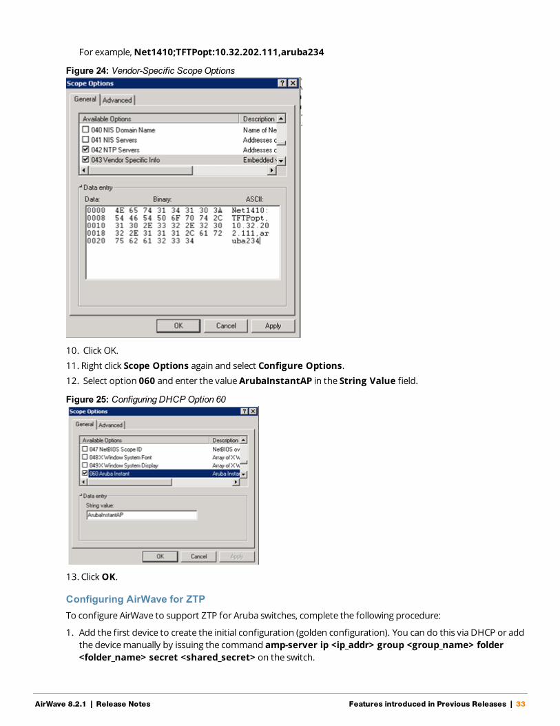
For example,Net1410;TFTPopt:10.32.202.111,aruba234
Figure 24: Vendor-Specific ScopeOptions
10. Click OK.
11. Right click Scope Options again and select Configure Options.
12. Select option 060 and enter the valueArubaInstantAP in the String Value field.
Figure 25: Configuring DHCP Option 60
13. Click OK.
Configuring AirWave for ZTPTo configure AirWave to support ZTP for Aruba switches, complete the following procedure:
1. Add the first device to create the initial configuration (golden configuration). You can do this via DHCP or addthe device manually by issuing the command amp-server ip <ip_addr> group <group_name> folder<folder_name> secret <shared_secret> on the switch.
AirWave 8.2.1 | Release Notes Features introduced in Previous Releases | 33

34 | Features introduced in Previous Releases AirWave 8.2.1 | Release Notes
2. Once the device state is UP on AirWave, navigate to APs/Device > Manage > Device Communication,enter the Telnet/SSH username and password, then confirm the password.
Before proceeding, verify that your configuration is in a good state.
3. Select the first device in theAPs/Devices > List page.
4. Navigate to theAPs/Devices > Audit page for that device.
5. Click the link to the device template on that page to open theGroups > Templates page.
Figure 26: Selecting the Device Template
6. In theGroups > Templates page, scroll down to theCredentials table.
7. In theChange credentials AMP uses to contact devices after successful config push field, selectYes.
8. (Optional) Enter a new Telnet/SSH username and password to change the credentials AirWave uses to contactthe devices.
9. Navigate to AMP Setup> General > Automatic Authorization.
10. In theAutomatically Authorized Switch Mode field, select theManage Read/Write option.
11.When you power on additional factory-default devices that match the same group and shared secret as the"golden config" device, those devices are automatically authorized, and receive their configurationinformation. The devices then reboot and up comes back up with a good configuration state.
Improved CAD ImportAirWave 8.2 introduces an enhancement to the importation of CAD (.dwg) files. When importing a CAD file toVisualRF, you are now given the option to define CAD layers as walls on your floor plan.
Beginning in 8.2, after uploading a CAD file, there is a new step on the Define New Floor page called CAD Layer.VisualRF generates a list of the layers in the uploaded CAD file. Any of the layer can then be defined as walls onthe floorplan.
To define a layer as walls, complete the following steps:
1. Check the checkbox to the left of the layer name to define it as walls.
2. Select the type of wall using the options in the drop-down list to the right of the layer name.
3. Click Next to continue defining the floor plan
Each floor plan is limited to 200 walls.

Figure 27: CAD Layer - VisualRF
Aruba Controller Configuration EnhancementsThe following additions have been made to AirWave's controller configuration options to supportArubaOS6.4.3.1. See the latest ArubaOS User Guide and CLI Guide for more information about each of thesenew fields.
l ARM Profile: Client Match 11v BSS Transition Management enables client match using 802.11vBSS Transition Management; this value is enabled by default. Client Match IOS Steer Backoff Intervalsets the backoff interval (in seconds) between IOS steering attempts.
l IKE Profile and Site to Site IKE Profile: Support added for Configure Hex Key and Disable IP COMP(Siteto Site IKE only) underAdvanced Services > VPN Services > Site to Site IKE for controllers runningArubaOS 6.4.3.0 and later.
l Virtual AP Profile: Supported added forWAN Operation under theVirtual AP Profile. This specifies thewan-operation to enable Virtual AP depending on the state of the WAN link. The default value is always butcan be changed to backup or primary.
l AAA Profile: Support added forOpen SSID Radius Accounting and Max IPv4 for Wireless User. OpenSSID Radius Accounting initiates RADIUS accounting as soon as the user associates to an Open SSIDwithout any authentication; disabled by default. Max IPv4 for Wireless User specifies the number of IPv4addresses that can be associated to single wireless user; the deafult value is two (2).
l Web SSH Management Profile: The following fields have been added to the Web SSH Management profilepage.
n Bypass Captive Portal Landing Page: if disabled, the controller uses the new redirection scheme alsoknown as the landing page by default including the meta tag. This can reduce the CPU load on thecontroller. The controller falls back to the old redirection scheme if this parameter is enabled. Disabled bydefault.
n Configure Lync Listen Port Access: Configures the port number on which the Skype4B plug-in sendsHTTP/HTTPS messages to the Aruba controller.
n TLS Protocol, TLS Protocol 1.1, TLS Protocol 1.2: Enables the TLS protocol version.
n IDP Certificate: Specifies the IDP certificate name configured in the controller.
l Session Access List: web-cc-category and web-cc-reputation are now supported services types.
AirWave 8.2.1 | Release Notes Features introduced in Previous Releases | 35

36 | Features introduced in Previous Releases AirWave 8.2.1 | Release Notes
l IPSEC Transform Set Profile: GCM encryption does not support hash algorithms from ArubaOS 6.4.3.1 orlater.
l AP System Profile: TheGRE Striping IP field has been removed from theAP System Profile.
l Netservice Profile: Fields forhttp-proxy and https-proxy have been added to theNetservice Profile toconfigure the application access level.
l Management Config: New options have been added to theManagement Config profile to DisableInline DHCP Stats,Disable Inline AP Stats,Disable Inline Auth Stats, and Disable Inline DNS Stats.These options are set to No by default.
VisualRF UI ChangesThe AirWave 8.2 VisualRF feature only supports the HTML5-based UI. AirWave 8.2 has deprecated the EnableHTML5-based UI setting added to theVisualRF > Setup > Server Settings page in AirWave 8.0, removing theoption to toggle between the legacy flash-based UI and the newer HTML5 UI.
The legacy flash-based VisualRF UI allowed users to add a wiring closet to a floor plan or create a client survey. Ifyou created a wiring closet or client survey in a previous release, this information is still be displayed in AirWave8.2, but cannot be modified.

37 | Features introduced in Previous Releases AirWave 8.2.1 | Release Notes

AirWave 8.2.1 | Release Notes Supported Infrastructure Devices | 38
Chapter 4Supported Infrastructure Devices
AirWave provides a range of features to manage network infrastructure devices from Aruba Networks and othervendors. AirWave 8.2.1 introduces support for the following Aruba and Hewlett Packard Enterprise products.
For a complete list of supported products from other vendors, see the AirWave 8.2 SupportedInfrastructure Devices document. You can find this document at support.arubanetworks.com.
Support for New Devices in AirWave 8.2.1This release of AirWave supports the following new devices
Aruba 7008 ControllerAirWave 8.2.1 introduces support for the Aruba 7008 controller.
Aruba Access PointsAirWave 8.2.1 introduces support for the Aruba AP-330 Series and AP-310 Series access points.
Aruba 2930F SwitchAirWave 8.2.1 introduces support for the Aruba 2930F switch.
Cisco 3800AP SwitchAirWave 8.2.1 introduces support for the Cisco 3800AP switch.
New Devices in AirWave 8.2.0AirWave introduces support for the following wireless access points, switches and access point module:
l AP-314, AP-315, AP-324, AP-325, AP-334, AP-335 Aruba access points
l IAP-324, IAP-325, ; Aruba Instant access points 4.2.4 (template configuration only)
l Aruba 2530YA switch*
l Aruba 2530YB switch*
l Aruba 2620 switch*
l Aruba 2920 switch
l Aruba 3800 switch
l Aruba 3810 switch
l Aruba 5400R switch
l APM-210 module (for Ericsson RBS 6402)
* These models do not support Zero-Touch Provisioning. Refer to "Known Issues" on page 46 for details.
Instant SupportAirWave 8.2.1 supports Aruba IAPs running Instant 6.4.4.6-4.2.4.0 and prior versions, including themanagement of configuration settings and software upgrades. The following table shows when each newversion of Instant was initially supported in AirWave.

39 | Supported Infrastructure Devices AirWave 8.2.1 | Release Notes
InstantVersion
Support for TemplateConfiguration
Support for IGC configuration
Instant 4.2.4 AirWave 8.2.1 and 8.2.0.3* AirWave 8.2.1, with the Instant 4.2.1 UI
Instant 4.2.3 AirWave 8.2 AirWave 8.2, with the Instant 4.2.1 UI
Instant 4.2.2 AirWave 8.2 AirWave 8.2, with the Instant 4.2.1 UI
Instant 4.2.1 AirWave 8.0.10.0 AirWave 8.0.10.0
Instant 4.2 AirWave 8.0.9 AirWave 8.0.9
Instant 4.1.3.1 AirWave 8.2.1, 8.2.0.3, and 8.0.11.2 AirWave 8.2.1, 8.2.0.3, and 8.0.11.2
Instant 4.1.3 AirWave 8.2.1, 8.2.0.3, and 8.0.11.2 AirWave 8.2.1, 8.2.0.3, and 8.0.11.2
Instant 4.1.2 AirWave 8.0.9 AirWave 8.0.9
Instant 4.1.1 AirWave 8.0.4 AirWave 8.0.4
Instant 4.1 AirWave 8.0 AirWave 8.0.4
Instant 4.0 AirWave 8.0 and AirWave 7.7.10 AirWave 7.7.8
Instant 3.4 AirWave 7.7.3 AirWave 7.7.8
Instant 3.3 AirWave 7.6.4 AirWave 7.7.8
Instant 3.2 AirWave 7.6.1 AirWave 7.7.5
Instant 3.1 AirWave 7.5.6 N/A
Instant 3.0 AirWave 7.5 N/A
Table 15: AirWave Support for Instant
*AirWave 8.2.0.3 supports template configuration for Instant 6.4.4.4-4.2.4.0, with the exception of the wired-port-profile<profile > [no] trusted command, which must be manually configured using the IAP command-line interface.

AirWave 8.2.1 | Release Notes Resolved Issues | 40
Chapter 5Resolved Issues
The following tables list issues resolved in AirWave 8.2.1 and prior releases.
ID Description
DE25427 Symptom: A controller does not automatically reboot if a firmware download operationfails.
Scenario: If the AirWave system boot process detects file copy failures during a firmwareupgrade, the reboot process will not initialize, and the switch will not reboot.
DE25735 Symptom: AirWave is now able to restore a backup file after an AirWave server upgradesfrom AirWave 8.0.x to AirWave 8.2.1.
Scenario: Improvements to how the internal server_watcher_limits file is handled resolvethis issue in AirWave 8.2.1.
DE25704 Symptom: AirWave 8.2.1 does not create duplicate entries for devices added via Activate ifthose devices are moved to another group.
Scenario: When an Mobility Access Switch is added to AirWave 8.2.1 via Activate Zero-TouchProvisioning and then moved into a group other than the group defined via Activate, aduplicate entry for that device no longer reappears in the original AirWave folder specifiedby Activate.
DE25599 Symptom: Planned APs correctly appear on an AirWave 8.2.1 VisualRF floorplan.
Scenario: An issue was identified in AirWave 8.2 that prevented planned APs fromappearing on a floorplan. This issue is resolved in AirWave 8.2.1 by improvements to theparsing of the internal catalog repository that maintains all of the values used by VisualRF.
DE25580DE25544
Symptom: An issue is resolved where Instant APs configured via the Instant GUI Config(IGC) feature could lose a configured PPPOE-password parameter and incorrectly add anadditional ACL entry.
Scenario: This issue occurred when IGC incorrectly identified a mismatch on the device, andattempted to modify the device configuration to resolve that mismatch. Internal changes inAirWave 8.2.1 prevent a mismatch from being incorrectly identified, resolving this issue.
DE25691 Symptom: APs placed in a VisualRF floorplan no longer shift location slightly when the pageis refreshed.
Scenario: When APs were placed on a small VisualRF floor plan configured with metric unitsand a small grid size, rounding errors in internal calculations made the AP change positionsslightly when the position was saved to the flooplan. This issue is resolved in AirWave 8.2.1.
DE25623 Symptom: An Instant AP image can not be uploaded via an external file server if an imagewith the same name is already uploaded to the AirWave server.
Scenario: The Device Setup >Upload Firmware & Files page of the AirWave WebUI nowsupports uploading files via an external file server, even if a file with the same name alreadyexists in the firmware list on the Groups > Firmware page.
Table 16: Issues Resolved in AirWave 8.2.1

41 | Resolved Issues AirWave 8.2.1 | Release Notes
ID Description
DE25540 Symptom: AirWave failed to import Cisco IOS templates from standalone APs.
Scenario: This issue has been fixed in AirWave 8.2.1.
DE25539 Symptom: AirWave 8.2.1 contains OpenSSL security updates for RHSA-2016:0996-2.
Scenario: Security flaws in OpenSSL could allow an application that is compiled against it tocrash, or execute arbitrary code, using the permissions of the user running the application.AirWave 8.2.1 includes enhancement for RHSA-2016:0996-2, which resolves vulnerabilitiesCVE-2016-2842, CVE-2016-2100, CVE-2016-2108, CVE-2016-2107, CVE-2016-2106, CVE-2016-2105, and CVE-2016-0799.
DE25509 Symptom: An issue is resolved where an Instant AP cluster appeared in an error state afterupgrading from Instant 4.1.1.13 to Instant 4.1.3.
Scenario: Changes to how the AirWave Instant GUI Config (IGC) feature handles Instantreleases with double digits resolves this issue in AirWave 8.2.1.
DE25472
DE24975
Symptom :AirWave 8.2.1 contains OpenSSL security updates for RHSA-2016:0301-1.
Scenario: Security flaws in OpenSSL allowed side-channel attacks, application crashes,decryption of RSA-encrypted cipher text, or allowed malicious SSLv2 clients to negotiateSSLv2 ciphers that were disabled on the server. AirWave 8.2.1 includes enhancement forRHSA-2016:0301-1, which resolves vulnerabilities CVE-2015-3197, CVE-2016-0702, CVE-2016-0705, CVE-2016-0797 and CVE-2016-0800.
DE25434 Symptom: An issue is resolved where a large number of alerts for high CPU or memoryusage were incorrectly triggered.
Scenario: An AirWave trigger configured as "Device Type is Access Point, Percent CPUUtilization >= 80% or Percent Memory Utilization >= 30% for 1 minutes" triggered many alertswhere the alert type appeared as "deleted" in the System > Alerts page. Improvements toCPU utilization processes resolve this issue in AirWave 8.2.1.
DE25421 Symptom: Some .dwg files were not correctly uploaded into VisualRF as floorplan images.
Scenario: Improvements to an internal image converter process resolves an issue wheresome .dwg images were not getting correctly converted to .svg images in VisualRF.
DE25385 Symptom: In previous releases of AirWave, filters applied to limit the display of roguedevices could not be removed all filters at once, but had to be removed individually.
Scenario: AirWave 8.2.1 resolves this issue with the addition of a new Reset filters link onthe RAPIDS > List page.
DE25382 Symptom: The default duration for a support connection is fourteen days in AirWave 8.2.1.In previous versions of AirWave 8.2.x, the default connection period was one day.
Scenario: A support connection is a point-to-point IP tunnel that is initiated from a customerAirWave server to Aruba's support server. A support connection on a server runningAirWave 8.2.1 remains open for seven days, unless it is manually closed using the command# service support_connection stop.
Table 16: Issues Resolved in AirWave 8.2.1 (Continued)

ID Description
DE25373 Symptom: When running a custom report with the Uptime by Device option selected,AirWave reported incorrect uptimes or reported devices as being down although they wererunning.
Scenario: This issue has been fixed by improvements to the order in which device uptimerecords are set.
DE25317 Symptom: The Clients > Diagnostics page inaccurately reported the channel width when itdisplayed 120 MHz for very high throughput (VHT) mode.
Scenario: The channels displayed are now correct for high throughput (HT) and VHTnetworks. Channels a device can use are: 20, 40, 80, or 160.
DE25282 Symptom: An AirWave server running AirWave 8.2.0.x sent random authentication requeststo the RADIUS server.
Scenario: This issue occurred only for RADIUS authentication, where unexpected RADIUSrequests were repeatedly sent to the RADIUS server, and continually failed.
DE24713 Symptom: Cisco 2700e LWAPP APs did not correctly display heat maps for 802.11ac radios,although heatmaps did correctly display for radios in 'ng' or 'na' modes.
Scenario: Updates to the internal catalog allows VisualRF to recognize Cisco 2700e LWAPPAP radios in 802.11ac mode.
DE24567 Symptom: Previous releases of AirWave 8.x generated two NMS events for the same rogueID classification if If a trigger is configured to forward an alert to another networkmanagement system.
Scenario: Improvements in AirWave 8.2.1 sends a single detailed alert for an NMS trap,rather than sending one NMS trap with details, and another NMS trap without details.
DE22575 Symptom: The Supported Platforms column in the interfaces table on the Groups >Controller Config > Local Config > Network > Port/Interfaces > Gigabit Ethernet pagenow correctly lists the Aruba 7205 controller.
Scenario: In previous releases of AirWave, the 7205 controller was incorrectly omitted as asupported platform for Ethernet interfaces that were supported by that device.
Table 16: Issues Resolved in AirWave 8.2.1 (Continued)
ID Description
DE25624 Symptom: AirWave did not generate matching event reports for an AP on the Reports >Detail page although it had connected clients.
Scenario: This issue occurred when AirWave skipped AMON messages that didn't containAP identification information. The method in which AirWave obtains the identificationinformation for an AP has been changed to resolve this issue.
DE25570 Symptom: When VisualRF ran calculations to build the campus grid, it generated largeamounts of data which resulted in extremely large backups.
Scenario: As a result of this issue, VisualRF ran out of memory and crashed. Visual RF now runscalculations in smaller intervals.
Table 17: Issues Resolved in AirWave 8.2.0.3
AirWave 8.2.1 | Release Notes Resolved Issues | 42

43 | Resolved Issues AirWave 8.2.1 | Release Notes
ID Description
DE25448 Symptom: Sometimes the Domain Name System (DNS) Resolution graph in the Claritydashboard wouldn't display.
Scenario: This graph wouldn't load because of an underlying ArubaOS issue, where the DNSsamples field populated when it shouldn't. The mechanism for querying the DNS samplesmeasured has been corrected.
DE25419 Symptom: Old JRE files remained after an upgrade.
Scenario: When upgrading from an earlier version of AirWave, a new JRE installs over itself,leaving JREs from previous installations. You can run a script and select which JRE files todelete. The script is in the /src/x86_64/rpms/Makefile directory.
DE25416 Symptom: After upgrading from AirWave 8.0.11.1 to 8.2.x, the Network view in VisualRFdisplayed incorrect results on the campus map.
Scenario: AirWave 8.2.0.3 fixes an issue where the data migration of pixel width and heightdidn't work during an upgrade from 8.0.11.x. Campuses no longer overlay each other on themap, and you can drag and drop, or auto arrange items again.
DE25408 Symptom: You could not modify the primary, secondary, or tertiary controllers from the CiscoThin AP Settings or the Manage Configuration page.
Scenario: After upgrading from an earlier version of AirWave to 8.2.0.1, you couldn't make aselection from the drop down menu, or access the drop down menu. These issues are resolvedfor all web browsers.
DE25352 Symptom: In the Usage graph for connected clients, accessed from the Client > Connectionpage, the labels and color codings were incorrect.
Scenario: The information in these graphs, such as color coding, axis direction, and clienttraffic direction, were changed to match other Usage graphs in the WebUI.
DE25346 Symptom: During an upgrade to AirWave 8.2.x, the system attempted to upgrade thefirmware after exceeding the maximum retries limit.
Scenario: The system now stops the upgrade when it reaches the maximum retries limit.
DE25320 Symptom: The row of statistics hyperlinks, called Top Header Stats, displayed incorrectly.
Scenario:AirWave 8.2.0.3 corrects this screen output issue.
DE25312 Symptom: Security flaws in the AirWave 8.0.x release could have caused an application that iscompiled against the NSS library to crash, or execute arbitrary code, using the permissions ofthe user running the application (CVE-2016-1978 and CVE-2016-1979).
Scenario: AirWave 8.2.0.3 contains the following Linux security updates, which correct theseissues:
l nss-util security update RHSA-2016:0370-1
l glibc security and bug fix update RHSA-2016:0175-1
l kernel security and bug fix update RHSA-2015:2636-1
l nss, nss-util, and NSPR security update RHSA-2016:0591-1
Table 17: Issues Resolved in AirWave 8.2.0.3 (Continued)

ID Description
DE25310 Symptom: AMON messages sent from ArubaOS controllers contain timestamps in variousformats.
Scenario: AirWave 8.2.1 resolves this issue by reporting all messages in the Clarity dashboardin milliseconds. In order to view complete Clarity data, upgrade AirWave to 8.2.0.3 and ensurethat the controller is running ArubaOS 6.4.3.9, 6.4.4.8, or later.
DE25067 Symptom: When you deploy an AP in a floor plan, VisualRF doesn't display a heatmap for theAP unless you restart VisualRF.
Scenario: VisualRF automatically refreshes and displays a heatmap for APs added to a floorplan.
DE24962 Symptom: The telnet_cmds log file tracks commands sent between AirWave and a deviceusing Telnet or SSH and might include passwords and secret data.
Scenario: Security enhancements in AirWave 8.2.1 prevent these files from being viewed usingthe WebUI and prevent them from being included in an AirWave backup file.
Table 17: Issues Resolved in AirWave 8.2.0.3 (Continued)
ID Description
DE25409DE25378
Symptom: Clients associated to an Instant AP correctly appear in VisualRF.
Scenario: In previous releases of AirWave 8.2.x, IAP clients did not appear correctly in VisualRFfloor plans.
DE25333 Symptom: AirWave 8.2.x processed incoming rogue data and didn't update the AP database.correctly.
Scenario: AirWave stores this rogue AP data and shows rogue devices accurately in theRAPIDs overview pages.
DE25314 Symptom: In the Home > Clarity Monitoring pages of the WebUI, the AP Name column in theAP Summary table and APs column of the AP Association table display the AP namedefined by the controller to which that AP is associated.
Scenario: AirWave displays the correct AP name sent by the controllerin the Clarity monitoringtables and graphs.
DE25260 Symptom An issue prevented AirWave 7.7.14 from upgrading to earlier releases of AirWave8.2.x.
Scenario: This issue is resolved by changes to the internal installation process that modifiedthe order in which some modules were installed.
DE25429 Symptom: The DNS failure graph on the Home > Clarity pages of the WebUI displayedinaccurate DNS data.
Scenario: Aruba controllers running ArubaOS 6.4.4.6 sent continuous server timeout errors. Asa result, the DNS failure graphs displayed inaccurate data. This issue has been resolved.
Table 18: Issues Resolved in AirWave 8.2.0.2
AirWave 8.2.1 | Release Notes Resolved Issues | 44

45 | Resolved Issues AirWave 8.2.1 | Release Notes
ID Description
US14749 Symptom: The accuracy of Clarity data is improved with a change that allows AirWave to useVLAN IP addresses to validate the source of the AMON messages sent to the AirWave server.
Scenario: This change resolves an issue that allowed the Home > Clarity Monitoring pages todisplay inaccurate information for the following deployments:l In a Master+Master-Standby controller deployment with VRRP and LMS IP set on the
controller, AMON AP messages were being sent with the LMS IP, preventing AirWave fromprocessing them.
l If messages were sent from the AP use a different VLAN IP than the controller, AirWavewould not process them correctly.
l If the IP address used by a single controller VLAN is defined as the IP address by whichAirWave communicates with the controller, AP station AMON messages sent from anyother VLAN IP defined on the controller would not be processed correctly by AirWave.
Table 18: Issues Resolved in AirWave 8.2.0.2 (Continued)
ID Description
DE25275
DE25251Symptom: An issue is resolved where an AirWave server upgrading to AirWave 8.2.0 mighthave insufficient disk space issue to allow the upgrade to completing successfully.
Scenario: This issue is resolved by changes to the internal upgrade procedures in AirWave8.2.0.1 that reduced the required disk space for the upgrade.
DE23592 Symptom: VisualRF correctly saves grid size modifications to floor plans.
Scenario: AirWave 8.2.0.1 resolves an issue that prevented VisualRF section of the AirWaveUI from saving modifications to the floor plan grid size property.
Table 19: Issues Resolved in AirWave 8.2.0.1
ID Description
DE23305 Symptom: VisualRF floor plans could display floor plan dimensions in feet, even if VisualRFwas configured to display metric units. AirWave 8.2 resolves this issue, and floor plandimensions are correctly converted from imperial to metric measurements.
Scenario: This issue was observed when VisualRF settings were changed to displaydimensions in metric units.
Table 20: Issues Resolved in AirWave 8.2

Chapter 6Known Issues
The tables below lists known issues identified in AirWave 8.2, 8.2.0.2, and 8.2.0.3 releases. There are no knownissues in AirWave 8.2.0.1.
ID Description
DE25926 Symptom: 2530YA, 2530YB and 2620 HPE Aruba switches fail to register with AirWave whenprovisioned via Zero-Touch Provisioning (ZTP) or configuration settings pushed from AirWave to theswitch command-line interface.
Scenario: This issue is triggered by OpenSSL updates in AirWave that caused a compatibility issue withthis device.
DE25875 Symptom: AirWave displays incorrect transmission power for APs running ArubaOS 6.4.4.0 to 6.4.4.6.
Scenario: For APs running the impacted versions of ArubaOS, transmission power levels on theAPs/Devices > Monitor page are displayed as twice the actual level on the AP, and VisualRF heatmapsmay display incorrect information. This issue is caused by changes in the information sent to AirWaveby the devices running these versions of ArubaOS.
DE25845 Symptom: The configuration snippet push to a ZTP device gets stuck in the "In Progress" state.
Scenario: After you start a partial configuration job for a group of factory-default devices added toAirWave via ZTP, you might see "In Progress" for the ZTP device in the Job Details table on the Groups> Templates > Partial Config page. This partial configuration option was designed for only Arubaswitches, and factory-default devices should not be available for selection from the partialconfiguration option.
DE25501 Symptom: EAP failures in 802.1X AMON messages are not monitored by AirWave.
Scenario: If clients with invalid certificates attempt to associate to AirWave, AirWave drops EAP_FAILURE Dot1x messages, preventing the tracking of clients which are facing EAP-FAILURE.
DE25400 Symptom:: The AirWave RAPIDs feature may incorrectly calculate signal strengths from the RSSI valuefor rogue devices.
Scenario: The cause of this issue is under investigation.
DE25399 Symptom: RAPIDS drops the event that corresponds to the strongest RSSI signal heard from a rogueAP.
Scenario: RAPIDS records the strongest signal heard for a rogue as the rogue entry's signal value anddoesn't overwrite that value until a stronger signal is heard, but RAPIDS may fail to retain the discoveryevent for that entry.
DE25350 Symptom: There is no support for pushing a full configuration for an Aruba switch running theArubaOS-switch Operating System using the secure file transfer protocols, SCP and SFTP.
Scenario: If you use the (unsupported) no tftp client CLI command, the switch is unable to accept TFTPrequests. As a result, AirWave cannot push full configurations to the switch.
Table 21: Known Issues in AirWave 8.2.1
AirWave 8.2.1 | Release Notes Rev. 01 | June 2016

ID Description
DE25268 Symptom: Database schema failures do not cause the upgrade process to halt.
Scenario: When a database schema change fails during a software upgrade, the upgrade processcontinues running.
DE24019 Symptom: When monitoring a stack of Aruba switches, or a standalone switch that has stacking-enabled, AirWave shows a junk record for a switch with a status of Unknown.
Scenario: This issue occurs when you remove the switch designated as commander from a stack andmove it to another part of the network. When SNMP discovery finds the switch in a new stack, the junkrecord disappears.
Table 21: Known Issues in AirWave 8.2.1 (Continued)
ID Description
DE25598DE25522DE25500
Symptom: After updating the IP address of the controller, you see syslog error messages listed underdevice events in the Clients > Detail page and not in the Clarity dashboard.
Scenario: Underlying issues with ArubaOS caused AirWave to report only DNS information in theClarity dashboard.
Workaround: In order to view complete Clarity data, upgrade AirWave to 8.2.0.3 or later, and ensurethat the controller is running ArubaOS 6.4.3.9, 6.4.4.8, or later.
DE25434 Symptom: AirWave sends hundreds of alerts for high CPU or memory usage.
Scenario: You might encounter this issue if you configured AirWave to send alert notification until it isacknowledged.
Workaround: When adding a trigger on the System > Triggers page, set the Suppress untilacknowledge option to Yes.
DE25324 Symptom: Upgrading from AirWave 8.0.x caused VisualRF beamwidth, orientation and gain values toreset to their default values.
Scenario: The beamwidth, orientation and gain values are not retained after flushing the bootstrap fileor upgrading the AirWave server.
Workaround: None.
DE25226 Symptom: AirWave takes longer to process station statistics AMON messages than it did in AirWave8.0.x.
Scenario: This issue has been associated with the Internet Explorer web browser.
Workaround: None.
Table 22: Known Issues in AirWave 8.2.0.3
ID Description
DE25398 Symptom: When you hover your mouse over the configuration ( ) icon on the Groups > List page,the popup window of available actions might not appear in the correct spot, be hidden out of view, ordisplay at the very bottom of the page.
Scenario: This issue has been associated with the Internet Explorer web browser.
Workaround: Use another web browser to access the WebUI, or select a group from the Groups >List page and use the navigation bar.
Table 23: Known Issues in AirWave 8.2.0.2
47 AirWave 8.2.1 | Release Notes

ID Description
DE25324 Symptom: VisualRF Beamwidth, Orientation and Gain values on deployed APs automatically reset whenyou upgrade AirWave to any version, or when you remove the bootstrap file.
Scenario: The beamwidth, orientation and gain values are not retained after flushing the bootstrap file orupgrading the AirWave server.
DE25220 Symptom: VisualRF indicated an incorrect number of APs associated with the AirWave server.
Scenario: In a deployment where over 4,000 APs were associated to an AirWave server, and the activeAPs status icon at the top of the WebUI page showed the correct number of APs, VisualRF incorrectlyindicated that AirWave had over 10,000 associated APs.
DE25154 Symptom: If an AP upgrades to Instant 4.2.3 and uses Lync applications in its access control rules, InstantGUI Config (IGC) may show a configuration mismatch for that device.
Scenario: This issue occurs because the list of Lync applications that can be included in an access controlrule in the AirWave 8.2 IGC feature differs from the list of available rules in Instant 4.2.3. The followingapplications are unsupported by IGC in AirWave 8.2.
l SOS ALG SVP l SOS ALG Facetime l SOS ALG Jabberl SOS ALG Vocera l SOS ALG Skype4B Voice l SOS ALG Jabber-MCl SOS ALG FTP l SOS ALG Skype4B Video l square applicationl SOS ALG RTSP l SOS ALG Skype4B File-Transfer l pearsonvue webl SOS ALG SIP l SOS ALG Skype4B l squirrelsystems webl SOS ALG NOE l SOS ALG SIP-Audio l learninganalytics webl SOS ALG SIPS l SOS ALG SIP-Video l youtubeeducation webl SOS ALG H323 l SOS ALG Skype4B Desktop-Sharing
DE25110 Symptom: If a switch IP address is changed from a static IP address to an IP address dynamicallyassigned via DHCP, the device may appear as down in AirWave.
Scenario: This issue is triggered because AirWave has no way to determine the IP address that will beassigned to the switch after the change to a DHCP-assigned IP address.
Workaround: Manually change the IP address when the IP provisioning option is changed from static toDHCP.
DE24785
DE24834
DE24836
DE24872
Symptom: When the Groups > Instant Config pages of the AirWave WebUI are accessed using theInternet Explorer web browser, these pages may not properly display Instant Config (IGC) configurationsettings or browser elements, and may not correctly save or update configuration changes.
Scenario: This issue occurs when you attempt to use Internet Explorer to create or modify a configurationfor Instant devices via Groups > Instant Config. This issue does not occur with other supported webbrowsers.
Possible IGC behaviors in Internet Explorer include the following:l Drop-down lists may not display properlyl Configured settings may not save or update properlyl Scrolling down a page in the IGC WebUI may cause the browser to unexpectedly return to the top of
the page.l Clicking the Save or Apply button may not save any configuration changes, may cause the browser to
unexpectedly return to the top of the page.
Workaround: Use an alternate web browser, such as Mozilla, to configure Instant devices.
Table 24: Known Issues in AirWave 8.2
AirWave 8.2.1 | Release Notes 48

ID Description
DE24424 Symptom: A non-default Failure Timeout value configured via AMP Setup > General > Firmwareupgrade/Reboot Options is not correctly applied.
Scenario: By default, if a firmware upgrade on a switch fails, that switch state is locked, and the switchcannot attempt another upgrade until the default failure timeout period of 60 minutes has elapsed. InAirWave 8.2, if you configure a non-default value for this failure timeout, the switch state may be lockedfor a time period equal to the default value of 60 minutes plus the new failure timeout period. Forexample, if you configure a custom failure timeout period of 15 minutes, that setting may keep a switchlocked in a pending state for 75 minutes, instead of the expected 15.
DE24417 Symptom: Firmware updates on Aruba switches may fail when firmware changes are simultaneouslysent to switches in a multi-level switch topology, where an upstream switch is located between adownstream switch and the AirWave server.
Scenario: This issue occurs when an upstream switch downloads the firmware image and reboots,temporarily disrupting the firmware download on the second, downstream switch. This disruption maycause the firmware upgrade on the second switch to fail.
Workaround: Perform separate firmware upgrades on switches at different levels. (For example,upgrade the first-level (upstream) switches before you upgrade any second level (downstream) switches.
DE24406 Symptom: Backup configurations downloaded from the AirWave WebUI are not compressed properly,cannot be restored.
Scenario: This issue occurs when a nightly backup file is downloaded using the Chrome web browser.
Workaround: Use an alternate web browser, such as Mozilla, to download the backup file.
DE24163 Symptom: The Current Secondary Version column in the System > Firmware Upgrade Job Detail >Devices Being Upgraded table displays incorrect image information for an Aruba switch.
Scenario: The Devices Being Upgraded table should display the version number for the software storedin the secondary flash in the Current Secondary Version column. This column may instead display theboot ROM software version.
Workaround: Access the switch command-line interface and issue the command show flash to view theprimary and secondary image versions.
DE24019 Symptom: The Member Switches table on the APs/Devices > Monitor page for an Aruba switch maydisplay incorrect stack member information.
Scenario: If a HPE 3810 stack is discovered via SNMP discovery on the network, and the stack memberwith commander status is moved to another stack, an invalid stack record may appear in the MemberSwitch table for members of the original stack.
Workaround: Adding another stack to the AirWave server may clear these invalid entries.
DE23592 Symptom: VisualRF does not correctly save modifications to floor plans.
Scenario: When modifying floor plans using the VisualRF section of the AirWave WebUI, changes to thefloor plans settings (like the floor name or number) are not correctly saved.
Workaround: Re-measure the floor plan to save modifications to the floor plan settings.
Table 24: Known Issues in AirWave 8.2 (Continued)
49 AirWave 8.2.1 | Release Notes

ID Description
DE23289 Symptom: VisualRF floor plans do not open correctly for clients accessing the AirWave WebUI via theMicrosoft Edge browser.
Scenario: When viewing the VisualRF section of the AirWave WebUI using the Microsoft Edge browser ona Windows 10 client, double clicking on a building or floor does not open the page for that building orfloor.
DE23281 Symptom: If the APs/Devices > Monitor page for a device displays a VPN IP address, hovering yourmouse over that VPN IP address displays a HTTPS and SSH tooltip that contains invalid links.
Scenario: This issue occurs because the VPN IP address displayed on that page is an internal IP address.Clicking the HTTP link in the tooltip displays a blank page, and on the SSH link does not log a user into anydevice.
DE19402 Symptom: Reports exported via FTP are not sent if the report is modified, as the modified report fails toauthenticate to the FTP server.
Scenario: This issue occurs when you modify an existing FTP report and do not re-enter the FTP serverpasswords in the Export Options section of the Reports > Definition > Export Options page.
Workaround: Redefine the FTP server password when you modify a report to be exported via FTP.
US14365 Symptom: PVOS commands values are unnecessarily grouped in the device running-config
Scenario: Some ArubaOS-Switch Operation System commands which are executed individually on theswitch appear in a group in the device running-config. AirWave supports a 1:1 comparison of commandsfrom the template and the device running-config, so this grouping may incorrectly cause the device toshow a mismatch.
For example, the template may show two separate commands:loop-protect transmit-interval 10
loop-protect disable-timer 3000
While the running-config groups these into a single line:loop-protect transmit-interval 10 disable-timer 3000
Workaround: Use the grouped command directly in the template to avoid a mismatch.
US14468 Symptom: PVOS commands values may vary between the template and device running-config
Scenario: When using template configuration to configure Power over Ethernet settings, the templatecommand power-over-ethernet pre-std-detect is modified in the running configuration to add portvalues. AirWave supports a 1:1 comparison of commands from the template and the device running-config, so this modification of the value may incorrectly cause the device to show a mismatch.
For example, the template may show the command:power-over-ethernet pre-std-detect
While the running-config adds port number valuespower-over-ethernet pre-std-detect ports 1-48
Table 24: Known Issues in AirWave 8.2 (Continued)
AirWave 8.2.1 | Release Notes 50

ID Description
US14468 Symptom: PVOS commands values may vary between the template and device running-config
Scenario: When using template configuration for 5400R, 3810, and 3800 Aruba switches, if the templatecommand ip aspath list does not include a sequence number, the running configuration applies asequence value of 5. AirWave supports a 1:1 comparison of commands from the template and the devicerunning-config, so this modification of the value may incorrectly cause the device to show a mismatch.
For example, the template may show the commands:ip aspath-list listname deny abcd
While the running-config adds a sequence number to the running configuration:ip aspath-list "listname" seq 5 deny "abcd"
US14471 Symptom: PVOS commands values may vary between the template and device running-config
Scenario: On 2530 and 2620 Aruba switches, some ArubaOS-Switch Operation System commands whichare executed individually on the switch appear in a modified format in the device running-config, whereleading zeros in a configuration value are added or deleted, and hexadecimal values in a templateconfiguration may appear in a decimal value in the running configuration. AirWave supports a 1:1comparison of commands from the template and the device running-config, so this modification of thevalue format may incorrectly cause the device to show a mismatch.
For example, the template may show the command:qos rate-limit dscp 0 1 kbps 0
While the running-config adds one or more leading zeros to the value:qos rate-limit dscp 000000 1 kbps 0
Workaround: Use the expanded command set in the template to avoid a mismatch.
Table 24: Known Issues in AirWave 8.2 (Continued)
51 AirWave 8.2.1 | Release Notes

ID Description
US14471 Symptom: Individual PVOS commands values are unnecessarily divided in the device running-config
Scenario: Some ArubaOS-Switch Operation System commands which are executed individually on theswitch appear in multiple lines in the device running-config. AirWave supports a 1:1 comparison ofcommands from the template and the device running-config, so this grouping may incorrectly cause thedevice to show a configuration mismatch.
For example, the template may show one individual command:ip source-interface all vlan 1
While the running-config divides the values from this command into multiple lines:
ip source-interface tacacs vlan 1
ip source-interface radius vlan 1
ip source-interface syslog vlan 1
ip source-interface telnet vlan 1
ip source-interface tftp vlan 1
ip source-interface sntp vlan 1
ip source-interface sflow vlan 1
Workaround: Use the expanded command set in the template to avoid a mismatch.
138330 Symptom: AirWave may not correctly display port statistics or interface information for managed nodesor Services Controllers running ArubaOS 8.0 beta
Scenario: This issue occurs when AirWave attempts to display information for managed nodes or aServices Controller running ArubaOS 8.0 beta in a topology where the Services Controller is installed on aserver VM.
137999 Symptom: AirWaveis unable to create a backup of the current configuration or flash memory on aService Controller running ArubaOS 8.0 beta.
Scenario: A user cannot use AirWave to issue the backup flash and copy flash commands create aServices Controller backup or copy the backup file to another location.
Workaround: Create a backup file for a Services Controller directly on that device.
137778 Symptom: AirWave may not correctly display the serial number for managed nodes or ServicesControllers running ArubaOS 8.0 beta.
Scenario: This issue occurs because AirWave 8.2 reads the serial number information from the legacyMIB OID wlsxSwitchLicenseSerialNumber, which does not return the correct serial number value.
Workaround: Access the command-line interface of the device and issue the command show inventoryto view the correct device serial number.
N/A Symptom: Due to a known issue on an Aruba switch (CR191863), the switch state does not change fromFactory to Non-Factory unless the switch reboots. If AirWave pushes a partial configuration that doesnot require a reboot, AirWave continues to see the switch in the Factory state.
Scenario: The switch UI page that allows you to fetch a template includes a Push completeconfiguration file: Device is rebooted after config push option. If a user selects No for this option ona factory-default switch provisioned via a DHCP server, AirWave only pushes a delta configuration, whichdoes not result in a switch reboot. If a user adds settings via AirWave that are not supported by AirWave8.2, the full configuration is not pushed and hence the unsupported commands are not applied on theswitch.
Table 24: Known Issues in AirWave 8.2 (Continued)
AirWave 8.2.1 | Release Notes 52

ID Description
N/A Symptom: If a user decides to reset the switch to a factory default state from the switch command-lineinterface, all stored passwords, security credentials and system settings will reboot in a factory defaultstate.
Scenario: This issue occurs because AirWave always executes the include-credentials command whenpushing a configuration to a switch.
N/A Symptom: Unrecognized PVOS command syntax.
Scenario: AirWave may not recognize some syntax for some ArubaOS-Switch Operating Systemcommands, and therefore will not allow to users to configure these commands via AirWave.
N/A Symptom: Unrecognized PVOS defaults and values.
Scenario: AirWave may not recognize some default values or the "no" syntax for some ArubaOS-SwitchOperating System commands, and therefore will not recognize these values when thesecommands are configured via AirWave.
For example, if a template has the command ipv6 hop-limit 100, AirWave would be expected to push thedefault value for this command ( 64 hops) if that line is removed from the template. If the default value ismissing from the command and not recognized by AirWave, the device could not return to its defaultvalue, and a configuration mismatch could occur.
Workaround: Issue the default value for the command within <push_to_exclude> tags in the template,as shown below.<push_to_exclude>
ipv6 hop-limit 64
</push_to_exclude>
N/A Symptom: Commands are hidden in the running-config.
Scenario: Some commands may be hidden by the switch in the running-config and CLI help. Additionalsteps may be required to add these command settings via template configuration.
Workaround: Add a hidden command to a device running config by including within <push_to_exclude>tags. For example, to ad the commands crypto key zeroize autorun rsa and crypto key zeroize ssh-client-key, to the template, use the following format:<push_to_exclude>
crypto key zeroize autorun rsa
crypto key zeroize ssh-client-key
</push_to_exclude>
Table 24: Known Issues in AirWave 8.2 (Continued)
53 AirWave 8.2.1 | Release Notes