akademin fÖr teknik och miljÖ - diva...
TRANSCRIPT

J
Uncertainty comparison of Digital Elevation Models derived from different image file formats
Ted Spring
2014
Examensarbete, Grundnivå (kandidatexamen), 15 hp Lantmäteriteknik
Lantmätarprogrammet, teknisk inriktning
Handledare: Yuriy Reshetyuk Examinator: Stig-Göran Mårtensson
Bitr. examinator: Mohammad Bagherbandi
AKADEMIN FÖR TEKNIK OCH MILJÖ Avdelning för industriell utveckling, IT och samhällsbyggnad


I
Foreword This thesis is written as a completion to the Land surveying programme at Högskolan i
Gävle. The subject was suggested by my supervisor Dr. Yuriy Reshetyuk and I would
like to thank him for his guidance. I would also like to thank Dr. Stig-Göran Mårtensson
for providing me with an Agisoft Photoscan license key, a digital camera and other
materials making it possible to perform this study.
Skärplinge, maj 2014
Ted Spring

II
Abstract
Unmanned Aerial Systems (UAS) have become increasingly popular recently for
surveying and mapping because of their efficiency in acquiring remotely sensed data in
a short amount of time and the low cost associated with them. They are used to generate
digital elevation models (DEM) derived from aerial photography for various purposes
such as the documentation of cultural heritage sites, archaeological surveying or
earthwork volume calculations.
This thesis investigates the possible effects different file formats may have on the
quality of elevation models. In this thesis, an UAS survey was simulated using a digital
camera to produce six DEMs based on JPEG, TIFF and RAW format in Agisoft
Photoscan by taking two sets of images of a city model, in different light conditions.
Furthermore, a reference DEM was produced in Geomagic Studio using data from a
Leica Nova MS50 Multistation. The DEMs were then compared in Geomagic Control.
The results from the 3D comparison in Geomagic Control show that the standard
deviation of all elevation models is 4 mm with the exception of the elevation model
derived from raw-edited images taken with lighting, which has a standard deviation of
nearly 6 mm. Also, all of the models have an average deviation of 0.4 mm or less. The
significant deviations in all DEMs occur in areas where the multistation lacked vision of
certain objects of the city model such as walls, or on the edges of the analysed area.
Additionally, the georeferencing results from Photoscan show that the DEMs based on
normal light condition images have slightly lower georeferencing errors than the DEMs
with lighting. It has been concluded that it is difficult to say whether file formats have
any noticeably effect on the uncertainty of digital elevation models.

III
Sammanfattning
Obemannade flygfarkoster (UAS – Unmanned Aerial Systems) har blivit alltmer
populärt inom mätning och kartering på grund av deras förmåga att enkelt och
kostnadseffektivt samla in information från luften på kort tid. De används för att skapa
digitala höjdmodeller från flygbilder för olika syften, exempelvis dokumentering av
kulturhistoriska platser, arkeologisk mätning eller volymberäkningar.
Detta examensarbete undersöker möjliga effekter olika filformat kan ha på kvaliteten på
digitala höjdmodeller. I denna studie simuleras en UAS-mätning med hjälp av en
digitalkamera för att skapa sex höjdmodeller baserade på filformaten JPEG, TIFF och
RAW i programmet Agisoft Photoscan Pro. Bilder togs i två omgångar med olika
ljusförhållanden. Ytterligare en modell skapades i Geomagic Studio utifrån data från en
Leica Nova MS50 Multistation. Denna modell användes som referens när jämförelser
av alla modeller utfördes i Geomagic Control.
Resultaten från 3D-jämförelsen i Geomagic Control visar att standardavvikelsen för alla
höjdmodeller är 4 mm med undantag för modellen som skapats utifrån bearbetade
RAW-bilder tagna med extra belysning, som har en standardavvikelse på nästan 6 mm.
Alla modeller har en medelavvikelse på 0,4 mm eller mindre. De största avvikelserna
förekommer i områden som multistationen saknade täckning, exempelvis väggar, och
på kanterna av det analyserade området. Dessutom visar resultaten från Photoscan att
höjdmodellerna baserade på bilder tagna under normala ljusförhållanden har lägre
georefereringsfel än motsvarande höjdmodeller baserade på bilder tagna med extra
belysning. Det har konstaterats att det är svårt att säga huruvida filformat har någon
slags inverkan på höjdmodellernas osäkerheter.

IV
Table of Contents 1 Introduction ................................................................................................... 1
1.1 Study objectives ........................................................................................ 3
1.2 Unmanned Aerial Systems ....................................................................... 3
Camera settings: ISO, shutter speed and aperture ........................... 3 1.2.1
1.3 File formats ............................................................................................... 4
JPEG ................................................................................................. 4 1.3.1
RAW ................................................................................................... 5 1.3.2
TIFF .................................................................................................. 6 1.3.3
1.4 Previous studies ........................................................................................ 6
2 Materials and methodology .......................................................................... 9
2.1 Object of study.......................................................................................... 9
2.2 Data collection .......................................................................................... 9
Image acquisition .............................................................................. 9 2.2.1
Laser scanning ................................................................................ 10 2.2.2
2.3 Data processing....................................................................................... 10
Agisoft Photoscan ............................................................................ 10 2.3.1
Geomagic Studio & Control ............................................................ 13 2.3.2
3 Results .......................................................................................................... 15
3.1 Quality of ground control points in Photoscan ....................................... 15
3.2 Digital elevation models produced in Photoscan ................................... 16
3.3 Comparison between DEMs in Geomagic Control ................................ 19
4 Discussion ..................................................................................................... 26
4.1 Quality of ground control points ............................................................ 26
4.2 Digital elevation models obtained in Photoscan ..................................... 27
4.3 Comparison between DEMs in Geomagic Control ................................ 28
5 Conclusion and outlook ............................................................................... 30
References ............................................................................................................. 31
Appendix 1 – Statistical reports from Agisoft Photoscan ..................................... 33
Appendix 2 – Statistical reports from Geomagic ................................................ 36

1
1 Introduction
Digital elevation models (DEM) provide important spatial information for
applications in various fields of studies such as geomorphology (Quédraogo,
Degré, Debouche & Lisein, 2014), hydrology, civil engineering, architecture,
archaeology and cultural heritage. They can be used to estimate heights of
buildings, trees and the terrain for planning purposes and general analyses of the
topography or for the documentation of archaeological and cultural heritage sites.
There are several different methods that can be used to acquire data for these
purposes. Common methods used include ground surveying with total stations,
laser scanners, Global Navigation Satellite Systems (GNSS) and remote sensing
techniques such as aerial photogrammetric data capture and Light Detection And
Ranging (LiDaR). Ground surveying is generally more accurate than aerial
surveying but more time consuming while aerial surveying can cover a larger
amount of terrain in a much shorter time. However, employing manned aircrafts
to survey small pieces of land that amounts only to a few km2 is an unnecessarily
expensive procedure (Quédraogo, et al., 2014). For this purpose, Unmanned
Aerial Systems (UAS) can be used. They are a cheaper alternative to manned
aerial surveys as well as ground surveying techniques such as laser scanning and
can be used for low altitude mapping.
It is important that these models have sufficient accuracy if they are to be used for
certain purposes such as the analysis of, for example, surface displacement and
fissures. Their applications are limited by their uncertainties, which in turn are
affected by data acquisition methods. Other factors that may affect the uncertainty
of these UAS products are scale, resolution, the quality of ground control points
(GCP), which are used for georeferencing images, as well as the software used for
processing (Niethammer, Rothmund, Travelletti & Joswig, 2012; Quédraogo, et
al., 2014). This thesis will investigate the potential influences different file
formats may have on the uncertainty of DEMs.
Pictures taken with a digital camera are always taken in raw format. But whether
they are stored for processing afterward or immediately converted, with pre-

2
defined settings, to JPEG or TIFF by the camera depends on the user and camera,
although not all cameras let the user store the image as RAW for further
processing (Verhoeven, 2010). JPEG is a file format that compresses image data,
resulting in a loss of information. This file format is widely used in digital
photography due to its small storage size. On the other hand, RAW file format is
uncompressed. The image is unprocessed, displays exactly what the camera sees
and is commonly referred as a digital negative. The quality of the image in its raw
format will not be degraded when printing it in JPEG or TIFF format, unlike when
editing JPEG images and printing them multiple times. However, there are some
disadvantages of using RAW file format in aerial photography, some of these
include the large file size and the time consuming process of RAW conversion.
RAW files are more than three times larger than JPEG files, requiring large
storage space. Furthermore, using RAW format means every single image must be
processed individually (Verhoeven, 2010).

3
1.1 Study objectives
The objective of this study is to investigate whether there is any difference in
quality of DEMs based on different file formats such as JPEG, TIFF and
postprocessed RAW images (exported as TIFF images from their raw format in
this study). Different contrasts in images are also investigated to see how contrast
affects the final result. This thesis is expected to answer the following questions:
• How is the uncertainty of the DEMs affected by different file formats • How do the file formats affect the digital elevation models, visually? • How do the different contrasts affect the quality of the elevation models?
1.2 Unmanned Aerial Systems
UAS is an all-encompassing term for all the components, including the aerial
vehicle, which are used to operate the unmanned system such as communication
link, ground station and launch s ystems. Unmanned Aerial Vehicles (UAV) refers
to the aerial vehicle itself and they are also known as drones. These drones were
initially used for military operations; however, in recent times these drones have
also demonstrated usefulness in civilian applications such as civil engineering,
agriculture, archaeological surveying and documentation of cultural heritage sites
by mounting them with digital cameras. These drones are controlled remotely
either manually or autonomously with GNSS. The more common types of UAVs
include helicopters and fixed-wings airplanes (Siebert & Teizer, 2014) but other
types also exist such as lighter weighted vehicles i.e. balloons, kites and helikites
(Mozas-Calvache, Pérez-García, Cardenal-Escarcena, Mato-Castro & Delgado-
García, 2011). By mounting these drones with digital cameras, products such as
digital surface models (DSM), digital elevation models (DEM) and orthophotos
can be photogrammetrically derived from acquired images that overlap each
other.
Camera settings: ISO, shutter speed and aperture 1.2.1
There are three main settings that control the exposure when taking pictures with
a digital camera: shutter speed, aperture and ISO. Shutter speed decides how long
the shutter is open for the sensor to be exposed to light. It is a measurement of

4
time in either seconds or fractions of seconds (1/20, 1/40, 1/60 etc.). A longer
shutter speed results in a longer exposure to light while a shorter shutter speed
results in shorter exposure to light. In photography, the shutter speed can be used
to control the effect of motion blur: either to freeze movement or to enhance
movement of an object. A faster shutter speed will capture and freeze very fast
moving objects while a slower shutter speed will result in motion blur (Nikon
Corporation, 2014a). Aperture is the opening of the camera lens which is where
the light travels through and is expressed as f/number i.e. f/2.8. Maximum
aperture varies by lens. A higher f-number reduces the aperture while a lower f-
number increases the aperture; these factors affect the depth of field in a
photograph. Depth of field refers to what appears to be in focus in a photograph
and higher f-number results in a deeper focus behind the focus point as well as in
front of the focus point while a lower f-number decreases the focus distance
behind the focus point and in front of it (Nikon Corporation, 2014b). ISO
(International Organization of Standardization) is the level of sensitivity of the
sensor. A lower ISO number means that the sensor’s sensitivity is reduced while a
higher ISO setting increases its sensitivity to light. However, if the ISO number is
too high, an increase in noise may occur, resulting in grainy images (Nikon
Corporation, 2014c).
It is important that these three settings are balanced in order to get the desired
result. Adjusting one setting means that the other settings should be adjusted as
well. By using a fast shutter speed, a higher ISO number is required. A low ISO
can be used with a slow shutter speed. If less light is required, aperture can be
adjusted as well.
1.3 File formats
JPEG 1.3.1
JPEG is a standard created by Joint Photographics Expert Groups (“JPEG”) for
storing digital images. It is widely used in digital photography. The file format is a
lossy image format which means that every time an image is saved as a JPEG file,
pieces of information is lost from the original image. Once an image has been

5
changed and saved, the original quality cannot be recovered. JPEG uses a
compression algorithm called Discrete Cosine Transform (DCT) and as explained
by Cabeen and Gent (1998), it separates the image into parts of differing
frequencies. In simple terms, the JPEG method divides the source data, i.e. the
image into 8x8 blocks of pixels. Then, the DCT matrix is applied to each block of
pixels moving from the upper left corner to the right and then working its way
down the whole image. The result is blocks of coefficients. The next step is
quantization which compresses every block. This is where the term “lossy”
originates from. During the quantization step the less important frequencies are
discarded. Quantization allows the user to decide the level of compression in
order to obtain desired image quality. There are different levels of compression,
for example high compression, medium compression and low compression. A
high level of compression results in a smaller sized, low quality image file while a
lower compression level results in a higher quality picture but larger file size. In
the final step of compression, the compressed blocks that constitute the image are
stored in a reduced amount space by converting all coefficients using an encoder
such as Huffman. In the final step, Inverse Discrete Cosine Transform (IDCT) is
used to reconstruct the image by decompression (Cabeen & Gent, 1998).
Advantages of using JPEG include the small file size and its compatibility with
web browsers, mobile phones, most software and applications for viewing and
editing.
RAW 1.3.2
RAW is a term that refers to different proprietary file formats. Different
companies have different formats. Some examples of these formats include .nef
(Nikon), .crw (Canon), .arw (Sony), .raf (Fuji) and .orf (Olympus). A raw file is
the recorded data from an analogue sensor that has been amplified and converted
to digital data. The data is left untouched when stored; it has not been processed
by the camera´s internal software with regard to settings such as white balance,
contrast, sharpening, saturation, and so on (Verhoeven, 2010). However, when
raw images are taken, metadata is also stored. Metadata is information related to
the image that has been taken with the camera. This information includes camera
settings, for example aperture, shutter speed, focal length as well as date and time

6
of shooting and if flash was used when taking the picture (Adobe Systems
Incorporated, 2004).
Compared to JPEG, raw format has the advantage of a higher bit depth in images.
Bit depth describes the amount of possible unique colours that can be displayed in
an image. A single bit image (1-bit, i.e. 1 and 0 in binary numbers) can display
two colours: black and white. A 4-bit image is limited to 16 colours since it can
attain a higher number of binary combinations (Florida Center for Instructional
Technology, 2011). JPEG are 8-bit files and can display 256 tones while raw files
are 12-bit or 14-bit. This means that when a picture is taken in JPEG mode, the
raw file is instantly converted to an 8-bit jpeg image. If an image is taken in raw
mode, it is possible to reach 4096 or 16384 tones. By processing an image in its
raw format and then storing it as an 8-bit file, the resulting image will be of better
quality than if the changes would have been performed on an 8-bit file. The
gradual change in tones and colours will not be as sharp and will instead have a
smooth transition (Canon Inc., 2014).
TIFF 1.3.3
Tagged Image File Format (TIFF) is a tag-based file format which is used to
describe and store raster images (Adobe Systems Incorporated, 1992). The tags
describe the content of a TIFF file such as dimensions of the image and copyright
data. TIFF format can either be compressed or uncompressed and store up to 16-
bit images. However, taking images in TIFF format, if possible (few digital
cameras allow one to capture TIFF images), provide no benefit over RAW as
TIFF files are even larger than RAW files and the internal camera software
processes the image just as in the case of images taken in JPEG format
(Verhoeven, 2010).
1.4 Previous studies
Most studies in UAS are about the possibilities of implementing UAS in a wide
array of applications, accuracy comparisons between 3D models derived from

7
UAS and other surveying techniques as well as its cost-effectiveness. While UAS
is a relatively new method, its accuracy was already assessed in 2006. A Mini
UAV was used to document a cultural heritage site called Pichango Alto in
southern Spain and it was possible to create a DSM with a 10 cm resolution and
0.6 cm standard deviation (Eisenbeiss & Zhang, 2006). In another study, UAS
was used to map the Super-Sauze landslide in France by producing high-
resolution ortho-mosaics and a digital terrain model (DTM) in order to analyse
fissures and surface displacements in the study area (Niethammer et al., 2012).
The produced DTMUAS was compared with a terrestrial laser scanner (TLS) based
DTM in order to assess the quality of the DTMUAS. Their result showed that the
RMS difference in the vertical direction is 0.31 m with some maximum deviations
reaching up to +3.44 and -4.08 m. Moreover, in a study by Douterloigne, Gautama
& Philips (2010), the authors investigated the uncertainty of a UAV produced 3D
landscape model. A total of 439 images were taken of a hill in five strips with a
90% forward overlap and a 60% sideward overlap at an altitude of 150 m. Their
3D model had an average uncertainty of 10 to 20 cm in all three directions.
In a comparative study by Naumann, Geist, Bill, Niemeyer and Grenzdörffer
(2013), an automatically generated DSM derived from UAS data was compared to
a DSM derived from TLS data. A dike with a dimension of 40 x 140 m was
surveyed with a UAV from a height of around 85 to 90 m, 5 strips were used to
cover the dike and surrounding terrain. 86 images were captured with a side
overlap exceeding 60%. The laser scanning campaign required 16 setups to cover
the same area; however, only points that were located at a maximum of 30 m
away from the scanner setup were used to produce the DSM. The comparison
resulted in a standard deviation of 4 cm, and if excluding outliers, 2.2 cm. The
authors also performed segment analysis of the dike. The standard deviations of
these segments were between 2 cm and 2.4 cm. Furthermore, they concluded that
the UAS model was slightly less accurate than the TLS model.
The quality of DEMs has been proven to be affected by positioning information.
Ruiz, Diaz-Mas, Perez and Viguria (2013) investigated how different positioning
systems affect the uncertainty of DEMs. In their study they performed an UAS
survey at scale 1:100 and used artificial objects to simulate buildings in smaller

8
scales. The scaled scenario that they used resulted in an 80-90 cm flying height,
corresponding to 80-100 m real flying height. In order to determine the position
and attitude of the aerial vehicle, they used an indoor aerial testbed with its own
localisation system which is based on 20 VICON cameras. For the system to
work, passive markers must be placed on the aerial vehicle. This system allows
for real-time positioning with a sample rate of 100 Hz. Normally, positioning
measurements are obtained by GPS/INS devices, but in this case these devices
have been replaced by the testbed system which will instead provide positioning
information. GPS receivers such as RTK/PPP, WAAS/EGNOS, DGPS and GPS
with SA deactivated were simulated by adding noise signals to the measurements.
RTK/PPP resulted in the lowest uncertainty in the generated DEMs, with an
uncertainty of 5.71 mm and 7.72 mm in horizontal and vertical direction,
respectively. In contrast, using GPS information resulted in an uncertainty up to
79.63 mm in vertical direction and 30.74 mm in horizontal direction. If these
results were to be transformed to the real scenario, the level of uncertainty would
reach decimeter levels. Additionally, they also evaluated the influence GCPs may
have on the end result. They used 5 GCPs in the scaled scenario and as a result,
the uncertainty levels were significantly reduced. The DEM based on GPS
information had its uncertainty reduced down to 5.4 mm and 3.73 mm in
horizontal and vertical directions, from its initial 30.74 mm and 79.63 mm
uncertainty.
There seem to be no earlier studies of possible uncertainty differences between
photogrammetric products derived from raw images and JPEG images in UAS.
However, Verhoeven (2010) argues the importance of using raw in aerial
photography, especially for remote sensing scientists, as it allows the
photographer a more complete control over the final output. The author compares
two images of an object, one in-camera generated JPEG image and a JPEG image
derived from a RAW workflow, taken from the same perspective. The in-camera
conversion disregarded all highlight details of the object, meanwhile processing
the RAW file allowed the highlight details to be brought back using the same
white balance, demosaicing algorithm and JPEG settings as the in-camera
conversion, making edges more distinguished.

9
2 Materials and methodology
2.1 Object of study
The object that was studied is a
round miniature model of a
housing area (figure 1) attached to
a wall. It has a diameter of 3 m
and the model consists of
buildings, roads, bridges, ridges,
elevated and depressed surfaces.
There are 16 GCPs distributed on
the model.
2.2 Data collection
Image acquisition 2.2.1
Two sets of photographs were taken, with each set consisting of 112 images. The
difference between these two sets was lighting condition: one set of photos was
taken with maximum lighting possible using lamps in order to illuminate the
model and ensure even distribution of light; the other set was taken under normal
lighting condition. All photographs were captured using a Nikon D7000 digital
camera from a distance of approximately 1.3 m (corresponding to 260 m in real
life) with an overlap of 75 %. The specifications of the camera are the following:
the sensor size is 23.6 x 15.6 mm, total pixels are 16.9 million and the focal length
of the camera lens is 35 mm. Both JPEG (high quality) and RAW format were
stored, resulting in a total of 548 files. The photographs were taken in eight strips
across the object, in a north-south direction, with 14 photographs in every strip. In
order to simulate an aerial photography and ensure the correct amount of overlap,
a wooden frame with threads crossing each other, a “grid net”, was placed in front
of the model. The aperture, ISO and shutter speed settings were set to f/2.8, 500
and 1/60, respectively. No vibration reductioner (also known as image stabiliser)
was used. The camera was not pre-calibrated.
Figure 1. Photograph of the study object. The red border indicates the coverage of taken photos. The white markers are the ground control points.

10
Laser scanning 2.2.2
The model was also scanned using a Leica Nova Multistation MS50. It integrates
traditional topographic surveying with 3D scanning and allows one to visualise
topographic data together with detailed high precision scans. Its maximum range
is up to 2000 m on reflectorless surfaces and up to 1000 m using Prisma GPR1.
Laser spot size is 8 mm x 20 mm at 50 m and its angle accuracy is 0.3 mgon
(Leica Geosystems, 2013). In this study the MS50 was set up obliquely towards
the scanning object at two locations in an arbitrary local coordinate system (X:
1000, Y: 1000, Z: 1000). The model was scanned, from two locations, at 1000
pts/s using a resolution of 3 mm at a distance of approximately 5 m. All of the 16
GCPs were also surveyed individually for the purpose of transforming the
coordinates of the point cloud to the coordinate system of the study object.
2.3 Data processing
The collected data was primarily processed in two different software: Agisoft
Photoscan Pro and Geomagic Studio/Control.
Agisoft Photoscan 2.3.1
Agisoft Photoscan Pro is a Structure-from-Motion (SfM) software which is used
to process photogrammetric data and produce orthophotos and DEMs from
images. To be able to reconstruct the geometry of a scene, it is required for the
scene to be visible from at least two cameras i.e. there must be sufficient overlap
between two images. In aerial photography with UAS, 60% of side overlap and
80% of forward overlap is sufficient (Agisoft, 2013). Photoscan uses information
from Exif data (such as camera type and focal length) to estimate the field of view
for each photo, which is used to reconstruct a 3D model (Agisoft, 2013). The
software and its applications have been reviewed by Verhoeven (2011) and it also
has been proven useful in UAS surveys for various purposes. Quédraogo et al.
(2014) used the Agisoft Photoscan to generate a DEM of agricultural watersheds
and Javernic, Brasington and Caruso (2014) used Agisoft for point cloud
processing in their research. The photo alignment process uses a structure from
11
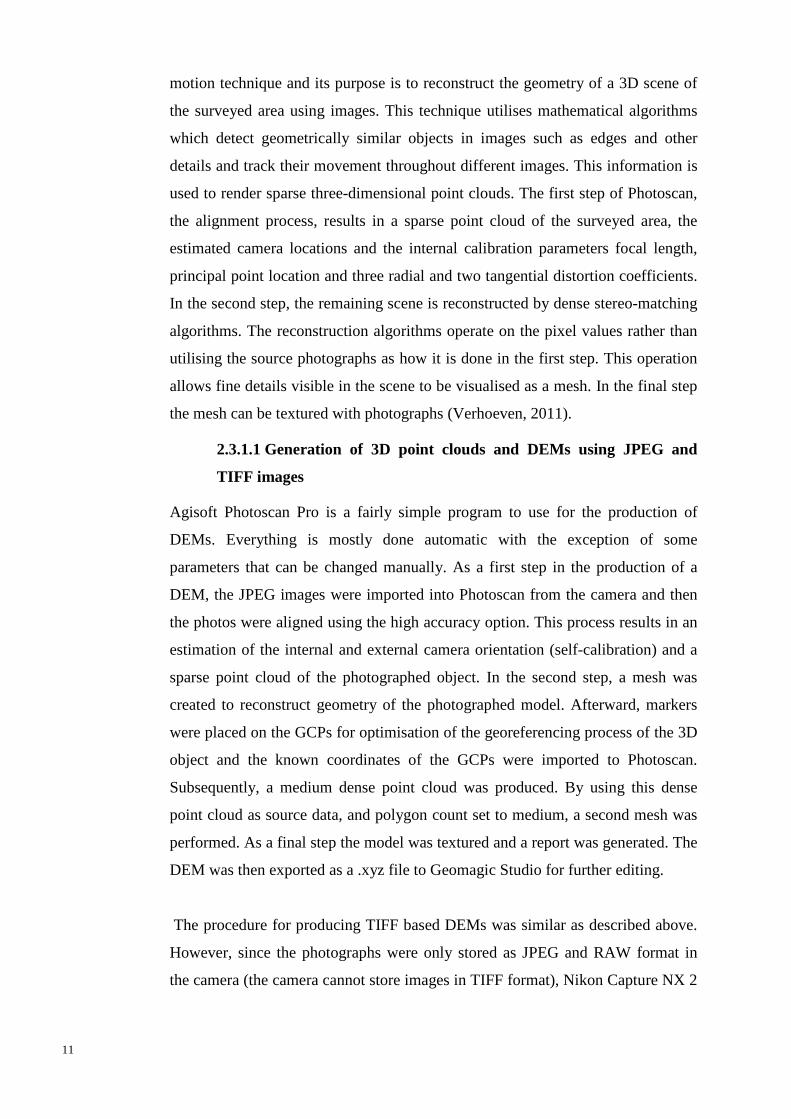
motion technique and its purpose is to reconstruct the geometry of a 3D scene of
the surveyed area using images. This technique utilises mathematical algorithms
which detect geometrically similar objects in images such as edges and other
details and track their movement throughout different images. This information is
used to render sparse three-dimensional point clouds. The first step of Photoscan,
the alignment process, results in a sparse point cloud of the surveyed area, the
estimated camera locations and the internal calibration parameters focal length,
principal point location and three radial and two tangential distortion coefficients.
In the second step, the remaining scene is reconstructed by dense stereo-matching
algorithms. The reconstruction algorithms operate on the pixel values rather than
utilising the source photographs as how it is done in the first step. This operation
allows fine details visible in the scene to be visualised as a mesh. In the final step
the mesh can be textured with photographs (Verhoeven, 2011).
2.3.1.1 Generation of 3D point clouds and DEMs using JPEG and
TIFF images
Agisoft Photoscan Pro is a fairly simple program to use for the production of
DEMs. Everything is mostly done automatic with the exception of some
parameters that can be changed manually. As a first step in the production of a
DEM, the JPEG images were imported into Photoscan from the camera and then
the photos were aligned using the high accuracy option. This process results in an
estimation of the internal and external camera orientation (self-calibration) and a
sparse point cloud of the photographed object. In the second step, a mesh was
created to reconstruct geometry of the photographed model. Afterward, markers
were placed on the GCPs for optimisation of the georeferencing process of the 3D
object and the known coordinates of the GCPs were imported to Photoscan.
Subsequently, a medium dense point cloud was produced. By using this dense
point cloud as source data, and polygon count set to medium, a second mesh was
performed. As a final step the model was textured and a report was generated. The
DEM was then exported as a .xyz file to Geomagic Studio for further editing.
The procedure for producing TIFF based DEMs was similar as described above.
However, since the photographs were only stored as JPEG and RAW format in
the camera (the camera cannot store images in TIFF format), Nikon Capture NX 2

12
was used to convert the RAW images to TIFF format. No editing was performed
and the standard camera settings that were used at the time of exposure were
applied to the images. After the conversion, the same procedure as mentioned
earlier was repeated.
2.3.1.2 Generation of 3D point cloud and DEM using processed raw
files in Nikon Capture NX 2
The RAW files of the two sets of images were imported to Nikon Capture NX 2
for further processing. Nikon Capture NX 2 is commercial software for processing
Nikon´s propetriary file format (.nef). It has many features with allows one to
control the final output of an image. Some of its features include the adjustment of
white balance, tonal curve, noise reduction, contrast adjustment, brightness
control, blurring etc. Images can be exported to JPEG, TIFF and RAW and it is
possible to keep the original raw file, allowing one to backtrack changes without
losing quality. Adjusted settings of one image can be stored and also be applied to
batches of images as well, making it unnecessary to process every photo
individually.
In the case of the images that were taken with lighting, due to excessive lighting
and low depth of field, sharpening reduction was applied to all images, contrast
was slightly increased and brightness value was decreased. It was only necessary
to apply localized brightness level changes to some GCP locations on individual
photos. However, since this would be a very time consuming process, these
adjustments were applied uniformly to all pictures. The differences between a
GCP in the original image and the raw edited image can be seen in figure 2 and 3.
Figure 2. Image of a blurry ground control point. Left: Raw-edited image. Sharpen filter has been applied and brightness and contrast levels have been changed. Right: JPEG quality.
Figure 3. Image of a better visible ground control point. Left: Raw-edited Image. Sharpen filter has been applied and brightness and contrast levels have been changed. Right: JPEG quality.

13
For the images that were taken with no lighting, only sharpen filter and noise
reduction were applied uniformly to all 112 images. After processing, they were
exported as TIFF images.
Geomagic Studio & Control 2.3.2
Geomagic Studio is a software with numerous functions which allows one to edit
point clouds, remove noise etc. as well as creating and editing meshes and surface
models based on these point clouds. Geomagic Studio can repair entire surface
models automatically, filling holes, deleting spikes, smoothing out surfaces etc.
Geomagic Control can perform some of Geomagic Studio´s functions as well but
its primary purpose is to assess the quality of products. It can perform 3D analyses
and compare point clouds to point clouds, point clouds to surface models or
surface to surface models, with one object set as “test” and the other as
“reference”. After an analysis, a 3D model is produced along with a colour scale
which shows the deviation distributions. It is possible to generate a report which
shows average, maximum and minimum deviation, standard deviations, and
deviation distribution in table format as well as in diagram format. The 3D
compare function allows one to choose between three different tolerance types:
3D, planar and directional.
2.3.2.1 Processing of Leica Nova MS50 Multistation data
Data from the multistation was processed in two types of software: SBG Geo and
Geomagic Studio. The scanning data was initially imported to SBG Geo in order
to do a coordinate transformation of the point cloud, transforming it from the local
coordinate system of the station to the coordinate system of the study object. This
was done using the GCPs located on the model, which were surveyed
individually, in a 3 parameter transformation (two translations and one rotation)
and an additional translation. However, before performing the coordinate
transformation, the point cloud had to be reduced from the initial 900 000 points
to 350 000 points since the process would take too long or sometimes the program
would not respond. Afterward, the point cloud was imported to Geomagic Studio
14
as a .xyz file for further processing. The point cloud was further reduced to about
300 000 points using the uniform function and noise was also removed. As a final
step before performing comparisons between the DEMs based on different file
formats and the DEMMS50, the point cloud was wrapped into a surface model. This
function, surface wrapping, also gives one the option to apply noise reduction. In
this case, the default option was used (auto). Due to the perspective of the
multistation when scanning, there were several holes in the resulting model,
especially on the walls of the buildings. These holes were filled using the “Fill
hole” function. The eastern side of the model was also cropped out because of too
many holes and the software could not properly reconstruct the buildings.
2.3.2.2 3D comparison in Geomagic Control
In the final step of the data processing, all models were imported into Geomagic
Control. These were then surface wrapped (with no noise reduction) and set to test
while the surface model based on multistation data was set to reference. The
comparison has to be done one by one. Lastly, a 3D compare was performed with
tolerance type set as 3D.

15
3 Results
A total of seven DEMs were created. Six of these were produced in Photoscan.
They were derived from digital images taken with different light conditions: with
lightning and without lighting. They are also based on three different file formats:
JPEG, TIFF and RAW (RAW in this case is actually TIFF format, but since the
images have been processed in their raw format, their respective model will be
referred to as DEMRAW to separate them from DEMTIFF which is based on non-
processed TIFF images). The other DEM was derived from multistation data and
produced in SBG Geo and Geomagic Studio.
3.1 Quality of ground control points in Photoscan
Photoscan presents its results in a report which shows the positions of the camera
at the time of exposure, image overlap, camera specifications, digital elevation
model, quality of control points etc. Since uncertainty of ground control points
affect the quality of DEMs, it would be relevant to present their qualities. Table 1
presents the total amount of error of all GCPs for each DEM type which were
obtained after optimising camera alignment in Photoscan.
Table 1. The total amount of error of all GCPs for each DEM type.
File format X error (m)
Y error (m)
Z error (m)
3D error (m)
Projections Error (pix)
With lighting
JPEG 0.000430 0.000367 0.000278 0.000630 281 0.379977
TIFF 0.000545 0.000578 0.000224 0.000826 281 0.418471
RAW 0.000385 0.000388 0.000262 0.000606 281 0.422192
No lighting
JPEG 0.000226 0.000222 0.000336 0.000462 284 0.313062
TIFF 0.000241 0.000316 0.000367 0.000542 286 0.392223
RAW 0.000304 0.000256 0.000308 0.000503 284 0.356550
In table 1 error (m) refers to the differences between the known coordinates of the
GCPs which were imported to Photoscan, and the estimated positions of the
markers that have been placed on the GCPs in Photoscan. Error (pix) refers to the
root mean square reprojection error for the markers that were manually placed on

16
the GCPs, which has been calculated over all photos where these markers are
visible (Agisoft, 2013). The three elevation models with no lighting have less total
error than the other three elevation models but have larger errors in Z-axis. The
coordinate differences for all 16 individual GCPs for each DEM is presented in
Appendix 1 (table A.1-A.6).
3.2 Digital elevation models produced in Photoscan
The digital surface models that were produced in Photoscan can be seen in figures
4-9. The green and red areas represent buildings while the dark blue areas
primarily represent the roads. The ground is represented by cyan. Of the two
models DEMJPEG and DEMTIFF (both with lighting), the maximum height is
33.7176 m as seen in figure 4 and 5. Their minimum heights deviate only by less
than a tenth of a millimeter, 33.5712 and 33.5711 m respectively.
Figure 4. DEMJPEG based on images taken with lighting.

17
Figure 5. DEMTIFF. based on images taken with lighting.
The DEM based on postprocessed RAW images which were taken with lighting
can be seen in figure 6. The maximum height is 33.7176 m and minimum height
is 33.5724 m.
Figure 6. DEMRAW derived from images taken with lighting..

18
The respective elevation models derived from the set of photographs taken under
normal light conditions can be seen in figures 7-9. The maximum height of the
DEMRAW, 33.7212 m, exceeds the maximum height of the DEMJPEG and DEMTIFF,
33.7196 m and 33.7174 m respectively. Meanwhile, of these three, the DEMTIFF
has the lowest minimum height at 33.5628.
Figur 7. DEMJPEG derived from images taken under normal light conditions.
Figure 8. DEMTIFF derived from images taken under normal light conditions.

19
Figure 9. DEMRAW under normal light conditions.
3.3 Comparison between DEMs in Geomagic Control
The results from the 3D comparisons between the DEMMS50 and the multiple
DEMs derived from digital images in Geomagic Control can be seen graphically
in figures 10-15 as well as their statistics in table 2. The DEMTIFF with lighting has
the highest standard deviation at nearly 6 mm and the DEMJPEG with lighting has
the lowest standard deviation at slightly less than 4 mm. All of the elevation
models have minimum and maximum deviations reaching centimeter levels with
the DEMraw (no lighting) having the highest maximum deviation at 0.0701 m. The
majority of the significant minimum deviations are located on the walls of the
buildings while the maximum deviations occur on the very edges of the models
and the walls.

20
Figure 10. 3D compare result in Gemoagic Control: DEMJPEG with lighting
Figure 11. 3D compare result in Geomacic Control: DEMTIFF with lighting.

21
Figure 12. 3D compare result in Geomacic Control:DEMRAW with lighting.
The point distributions within each model are presented in appendix 2. For models
with lighting, 81 % of points are distributed within one standard deviation from
the mean in DEMJPEG, 83% of the points are distributed within one standard
deviation from the mean in DEMTIFF and 79% of the points are distributed within
one standard deviation from the mean in DEMRAW. For the DEMs with no
lighting, 77% and 80% of the points are distributed within one standard deviation
from the mean in DEMTIFF and DEMJPEG, respectively. For the DEMRAW, 80% of
the points are distributed within one standard deviation from the mean.
Figure 13. 3D compare result in Geomacic Control: DEMJPEG with no lighting.

22
Figure 14. 3D compare result in Geomacic Control: DEMTIFF with no lighting
Figure 15. 3D compare result in Geomagic Control: DEMRAW with no lighting.

23
Table 2. Results from 3D compare in Geomagic Control. The table shows standard deviations of DEMs based on different file formats and light conditions. Data from Leica Nova Multistation MS50 served as reference data. No lighting With lighting
File format JPEG TIFF RAW JPEG TIFF RAW
Outliers 190 113 548 44 18 17
Min
deviation (m)
-0.0452 -0.0475 -0.0692 -0.0326 -0.0438 -0.0331
Max
deviation (m)
0.0417 0.0220 0.0701 0.0202 0.0697 0.0351
Average
deviation (m)
0.0003 0.0001 0.0004 0 0.0004 0.0001
Standard
deviation (m)
0.0044 0.0043 0.0043 0.0039 0.0056 0.0041
RMSE 0,0045 0,0043 0.0044 0,0040 0,0057 0,0041
The locations of the maximum and minimum deviations of the elevation models
as presented in table 2 can be seen in figure 16. They are located primarily on the
edges of the analysed area and on the walls.
Figure 16. Maximum (red dot) and minimum (blue dot) deviations of the elevation models. In order 1 to 6: DEMJPEG with lighting, DEMJPEG with no lighting, DEMTIFF with no lighting, DEMTIFF with lighting, DEMRaw with lighting, DEMRAW with no lighting.
A detailed view of one of the walls where
there is constant noteable discrepancies
reaching up to 2 cm between the reference
and test objects is presented in figure 17.
A sample of the discrepancies that occur in the typical areas with large deviations
is shown in figure 18, they primarily deviate in Z-axis.
Figure 17. Side view of the model. This discrepancy occurs in all six models.

24
Figure 18. Deviations in all three directions of DEMRAW.

25
Table 3 presents the errors of the maximum and minimum deviations from table 2 and figure 16 in all three directions.
Table 3. Upper and lower deviations of specific DEM type.
With lighting
DEMRAW Dev X (m) Dev Y (m) Dev Z (m)
Lower dev. -0.0001 -0.0327 0.0050
Upper dev. -0.0180 -0.0301 -0.0019
DEMJPEG
Lower dev. 0.0225 0.0080 -0.0222
Upper dev. -0.0201 -0.0023 -0.0012
DEMTIFF
Lower dev. 0.0111 -0.0423 -0.0013
Upper dev. 0.0645 -0.0256 0.0062
No lighting
DEMJPEG Dev X (m) Dev Y (m) Dev Z (m)
Lower dev. 0.0099 -0.0439 -0.0041
Upper dev. -0.0019 -0.0102 -0.0404
DEMTIFF
Lower dev. 0.0343 -0.0133 -0.0300
Upper dev. -0.0208 -0.0072 -0.0012
DEMRAW
Lower dev. 0.0293 0.0626 0.0028
Upper dev. -0.0668 0.0214h 0.0018

26
4 Discussion
4.1 Quality of ground control points
It should be noted that the photographs captured with the digital camera were not
of desired quality. They suffered from an insufficient depth of field and larger
areas were out of focus, resulting in a large amount of blur in some photos. The
blur was not visually apparent unless zoomed in. The photographs appeared to be
of good quality when looking at the small camera display but when uploaded to a
computer with a larger display, the blur became more apparent. The blurring
noticeably affected some of the ground control points, as can be seen in figure 2.
The images that were taken with lighting were subject to substantially more
blurring than the images that were taken under normal light conditions. What
should be a cross has instead become a small, blurry dot. This led to a not entirely
correct placement of markers on top of the ground control points in Photoscan. As
the purpose of these markers is to optimise the photo alignment procedure and
improve georeferencing, the subsequent consequences of inaccurate placement of
markers lead to increased georeferencing errors.
Similarly, the amount of brightness also affected the quality of ground control
points to a certain degree. Some GCPs in the photographs that were taken with
full illumination were overexposed (or rather, the material of the GCPs seemed to
have reflected the lighting), making it difficult to identify the centre of the GCPs.
It was possible to reverse this effect to a very small degree by editing the original
raw file of the JPEG images, applying sharpen filter and adjusting contrast and
brightness levels.
In light of this, by looking at the quality of GCPs in table 2, it is difficult to
determine whether the different formats have had any effect on the georeferencing
results in Photoscan. If comparing the DEMJPEG with DEMRAW (both with
lighting), the total GCP error decreases minimally. However, despite editing of
the RAW images, the GCP error for certain individual GCPs increased rather than
decreased (which can be seen by comparing table 1 and 3 in Appendix 1). It is

27
also interesting to note that both of the two DEMTIFF have a larger total error than
their respective DEMJPEG. But like the previous case, the individual GCP error
differs, making it difficult to conclude whether either format is better than the
other. It is safe to assume that due to the impossibility of being able to correctly
locating the centre of GCPs, the differences are more likely caused by ill-defined
GCPs in the images rather than different file formats. The fact that the TIFF-based
DEMs have a larger total GCP error than their JPEG counterparts is more likely
caused by chance when placing the markers. However, it can be concluded that in
this case no lighting is better than with lighting since the GCPs were not as blurry
in these images.
4.2 Digital elevation models obtained in Photoscan
The six digital elevation models (figures 4-9) that were obtained in Agisoft are
nearly identical, visually (except for the DEMTIFF in figure 5 which appears to
have had its upper left corner cut off when editing) and statistically. The
maximum heights of all DEMs derived from images taken with lighting are
identical while their minimum heights deviate 1 mm at most. On the other hand,
the maximum heights of the DEMs derived from images taken without lighting
are all different, with up to a 4 mm difference. The DEMJPEG and DEMTIFF deviate
by only 2 mm, but the height of the DEMRAW exceed the maximum heights of all
DEMs. A large difference in minimum height is also found between the DEMJPEG
and DEMTIFF, up to a 7 mm difference. This is most likely not caused by different
file formats, considering the differences between the models derived from images
taken with lightning are all miniscule. It is doubtful if the qualities of the GCPs
have had any effect on the models since the differences are miniscule. In other
words, the differences are unexplainable. Although a possible reason may be
overlooked spikes at the time of editing the created mesh, as there were significant
amount of spikes in all created meshes.
It would have been interesting to compare the quality of these DEMs produced in
Photoscan with DEMs produced in another software. Quédraogao et al. (2014)
produced two DEMs with a spatial resolution of 1 x 1 m in both Agisoft

28
Photoscan and a software called MicMac and compared them with a DEM derived
from terrestrial laser scanner data. Their results showed that the DEM generated
in MicMac was more accuracte: it had a RMSE value of 9.0 cm compared to the
13.9 cm of the DEM generated in Photoscan.
4.3 Comparison between DEMs in Geomagic Control
There appears to be only a minimum difference between the elevation models
when looking at the standard deviations in table 2. The DEMTIFF with lighting
deviates from the rest, with its standard deviation nearly reaching 6 mm compared
to the others with 4 mm standard deviations. According to Eisenbeiss and Zhang
(2006), it is possible that slight increases of standard deviations are caused by
outliers. Like this study, they also used Geomagic Control to assess the accuracy
of elevation models by comparing a DEM derived from UAV data and a DEM
derived from laser scanner data. However, outliers do not seem to explain the
slight increase in standard deviation for the DEMTIFF. It merely has 18 outliers
compared to the 548 outliers in the DEMRAW with no lighting.
If one is looking at the discrepancies in figure 18, it would seem that they mostly
occur in z-axis. However, the minimum and maximum deviations have larger
errors in all three directions as seen in table 3. The large deviations on the walls
(blue areas in figures 10-16) are caused by the multistation’s inability to reach
those areas. These deviations occur due to the nature of the multistation scanning
perspective (as it was scanning the buildings from the same perspective as the
pictures that were taken) and it was impossible to cover them, but the
discrepancies such as the ones in figure 17 should be non-existing with a second
set up of the multistation. The multistation was setup at the two locations, but due
to an unknown error resulting in an off-set of the point cloud in one axis, this data
had to be discarded. Although it was possible to import specific parts of this point
cloud to the point cloud of the first setup location, it still was not enough to cover
those areas. The amount of discrepancy seems to vary by each DEM type. This is
caused by the initial point clouds that Photoscan produced. Some of the point
clouds had zero points on these walls while others had very little or very much.

29
Likewise, some parts of the roof tops and the roads at one side of the model have
a slight increase in deviation from the reference data; however these deviations
are most likely caused by noise as the field of view of the multistation allowed
clear view of these parts. The point cloud obtained from the multistation had a
large amount of noise and despite manual editing and noise reduction in
Geomagic Studio; it was not possible to get a smooth surface. A possible reason
for occurrences of noise at these locations may be the reflectance of the material,
resulting in an off-set of the range. The range is dependent on the power of the
reflected signal: the reflectance of a material affects the power of a returning
signal. If the reflected signal is too powerful or too weak, the measured distance
will be shorter or longer, respectively, than the correct distance (Reshetyuk,
2012). Another reason may be the incidence angle. The incidence angle was larger
when scanning these locations. A higher incidence angle results in a weaker return
signal (Soudarissanane, Lindenbergh, Menenti & Teunissen, 2009) which may
possibly influence the uncertainty of the measurements. The discrepancy on the
roof tops deviates from the reference DEM by up to 9 mm in z-axis and the
discrepancies on the road areas reach up to 5 mm in z-axis.

30
5 Conclusion and outlook
Six types of DEMs based on JPEG, TIFF and RAW format have been presented.
Their qualities have been assessed by comparing the different DEM types with a
DEM derived from multistation data. Visually and statistically there were small
differences between the six DEM types. In this investigation, it can be concluded
that the different file formats (JPEG, TIFF, RAW) do not affect the quality of
DEMs significantly, if anything. However, further testing is required to be able to
truly determine if this is truly the case. Preferably the testing should be performed
in the real environment. A problem with the model used in this study is the lack of
complex objects. Also, rather than taking two sets of images with different
contrasts, a better idea would be to take one set of images and then edit the raw
files in order to decrease (or increase) contrast levels. One of the initial purposes
was to compare DEMs based on low contrast images and high contrast images,
but due to the low quality of the images taken with lighting it would be hard to
make a fair comparison in this study. The GCPs in those images were too blurry
and even raw editing was unable to save them. Editing ever single image
individually would take a long time, but in this case the software used for editing
allowed one to apply adjustments of one image to a batch of images, reducing
processing time by a lot.

31
References
Adobe Systems Incorporated. (1992). TIFFTM Revision 6.0. Retrieved 2014-06-22, from https://partners.adobe.com/public/developer/en/tiff/TIFF6.pdf Adobe Systems Incorporated. (2004). Understanding Digital Raw Capture. Retrieved 2014-05-21, from http://wwwimages.adobe.com/www.adobe.com/content/dam/Adobe/en/products/photoshop/pdfs/understanding_digitalrawcapture.pdf Agisoft. (2013). Agisoft PhotoScan User Manual: Professional Edition, Version 1.0.0. Retrieved 2014-05-21, from http://downloads.agisoft.ru/pdf/photoscan-pro_1_0_0_en.pdf Cabeen, K. & Gent, P. (1998). Image Compression and the Discrete Cosine Transform. California, United States: College of the Redwoods Retrieved 2014-5-14, from http://msemac.redwoods.edu/~darnold/math45/laproj/Fall98/PKen/dct.pdf Canon Inc. (2014). Capturing the image: 8 or 16 bit. Retrieved 2014-05-21, from http://cpn.canoneurope.com/content/education/infobank/capturing_the_image/8_or_16_bit.do Douterloigne, K., Gautama, S., & Philips, W. (2010). On the accuracy of 3D landscapes from uav image data. Geoscience and Remote Sensing Symposium (IGARSS), IEEE International. 589 – 592, doi:10.1109/IGARSS.2010.5651391 Eisenbeiss, H. & Zhang, L. (2006, September). Comparison of DSMs generated from mini UAV imagery and terrestrial laser scanner in a cultural heritage application. Paper presented at ISPRS commission V symposium ”image engineering and vision metrology”, Dresden, Germany. Florida Center for Instructional Technology. (2011). What is bit depth?, University of South Florida. Retrieved 2014-07-03 from http://etc.usf.edu/techease/win/images/what-is-bit-depth/ Javernick, L., Brasington, J. & Caruso, B. (2014). Modeling the topography of shallow braided rivers using Structure-from-Motion photogrammetry, Geomorphology, 213, 166-182. doi:10.1016/j.geomorph.2014.01.006 Leica Geosystems. (2013). Leica Nova MS50 Data sheet. Retrieved 2014-05-21, from http://www.leicageosystems.com/downloads123/zz/tps/nova_ms50/brochures-datasheet/Leica_Nova_MS50_DAT_en.pdf Mozas-Calvache, A.T., Pérez-García, J.L., Cardenal-Escarcena, F.J., Mata-Castro E. & Delgado-García J. (2011). Method for photogrammetric surveying of archaeological sites with light aerial platforms. Journal of Archaeological Science, 39 (2012), 521-530. doi: 10.1016/j.jas.2011.10.007

32
Niethammer, U., James M.R., Rothmund S., Travelletti J. & Joswig M. (2012). UAV-based remote sensing of the Super-Sauze landslide: Evaluation and results. Engineering Geology, 128, 2-11. doi: 10.1016/j.enggeo.2011.03.012 Naumann, M., Geist, M., Bill, R., Niemeyer, F., & Grenzdörffer, G. (2013). Accuracy comparison of digital surface models created by unmanned aerial systems imagery and terrestrial laser scanner, Int. Arch. Photogramm. Remote Sens. Spatial Inf. Sci., XL-1/W2, 281-286, doi:10.5194/isprsarchives-XL-1-W2-281-2013. Nikon Corporation. (2014a). Digital SLR Camera Basics. Retrieved 2014-06-17, from http://imaging.nikon.com/history/basics/04/03.htm Nikon Corporation. (2014b). Digital SLR Camera Basics. Retrieved 2014-06-17, from http://imaging.nikon.com/history/basics/04/04.htm Nikon Corporation. (2014c). Digital SLR Camera Basics. Retrieved 2014-06-17, from http://imaging.nikon.com/history/basics/13/index.htm Quédraogo, M.M., Degré A., Debouche C. & Lisein. J. (2014). The evaluation of unmanned aerial system-based photogrammetry and terrestrial laser scanning to generate DEMs of agricultural watersheds. Geomorphology, In press, Corrected Proof. doi: 10.1016/j.geomorph.2014.02.016 Reshetyuk, Y. (2012). Introduction to terrestrial laser scanning. Gävle: University of Gävle Ruiz, J. J., Diaz-Mas, L., Perez, F., & Viguria, A. (2013). Evaluating the accuracy of DEM generation algorithms from UAV, Int. Arch. Photogramm. Remote Sens. Spatial Inf. Sci., XL-1/W2, 333-337, doi:10.5194/isprsarchives-XL-1-W2-333-2013
Siebert, S. & Teizer, J. (2014). Mobile 3D mapping for surveying earthwork projects using an Unmanned Aerial Vehicle (UAV) system. Automation in Construction, 41, 1-14. doi: 10.1016/j.autcon.2014.01.004 Soudarissanane, S., Lindenbergh, R., Menenti, M. & Teunissen, P. (2009, September). Incidence angle influence on the quality of terrestrial laser scanning points. Paper presented at ISPRS commission WG V/3 in proceedings of laser scanning 2009, Paris, France. Verhoeven, G. J. J. (2010). It's all about the format – unleashing the power of RAW aerial photography, International Journal of Remote Sensing, 31 (8), 2009-2042, doi: 10.1080/01431160902929271 Verhoeven, G. (2011). Taking Computer Vision Aloft – Archaeological Three-dimensional Reconstructions from Aerial Photographs with PhotoScan, Archaeological Prospection, 18 (1), 67-73. Doi: 10.1002/arp.399

33
Appendix 1 – Statistical reports from Agisoft Photoscan
Table A.1. Optimised georeferencing results for DEMJPEG with lighting.
Table A.2. Optimised georeferencing results for DEMTIFF with lighting.

34
Table A.4. Optimised georeferencing results for DEMJPEG without lighting.
Table A.3. Optimised georeferencing results for DEMRAW with lighting

35
Table A.5. Optimised georeferencing results for DEMTIFF without lighting
Table A.6. Optimised georeferencing results for DEMRAW without lighting.

36
Appendix 2 – Statistical reports from Geomagic
Statistical report from Geomagic Control for DEMs with lighting. Left: DEMJPEG. Right: DEMTIFF

37
Statistical report from Geomagic Control for DEMs with lighting. DEMRAW

38
Statistical report from Geomagic Control for DEMs without lighting. Left:
DEMJPEG. Right: DEMTIFF

39
Statistical report from Geomagic Control for DEMRAW without lighting.