al and the sea
TRANSCRIPT

33
Alc
an M
arin
e
1. The series of wrought alloys . . . . . . . . . . . . . . . . . . . . . . . . . . . . . . . . . . . . . . . . . . . . . . . . . . . . . . 36
2. Designation of wrought aluminium alloys . . . . . . . . . . . . . . . . . . . . . . . . . . . . . . . . . . . . . . . . . 36
3. Strain hardening alloys . . . . . . . . . . . . . . . . . . . . . . . . . . . . . . . . . . . . . . . . . . . . . . . . . . . . . . . . . . 373.1 Softening by annealing . . . . . . . . . . . . . . . . . . . . . . . . . . . . . . . . . . . . . . . . . . . . . . . . . . . . . . . . . . . . . . 373.2 Tempers . . . . . . . . . . . . . . . . . . . . . . . . . . . . . . . . . . . . . . . . . . . . . . . . . . . . . . . . . . . . . . . . . . . . . . . . . 38
4. Age hardening alloys . . . . . . . . . . . . . . . . . . . . . . . . . . . . . . . . . . . . . . . . . . . . . . . . . . . . . . . . . . . . 394.1 Principle of age hardening . . . . . . . . . . . . . . . . . . . . . . . . . . . . . . . . . . . . . . . . . . . . . . . . . . . . . . . . . . . 394.2 Softening by annealing . . . . . . . . . . . . . . . . . . . . . . . . . . . . . . . . . . . . . . . . . . . . . . . . . . . . . . . . . . . . . . 404.3 Designation of tempers . . . . . . . . . . . . . . . . . . . . . . . . . . . . . . . . . . . . . . . . . . . . . . . . . . . . . . . . . . . . . 41
5. The principal alloys for marine applications . . . . . . . . . . . . . . . . . . . . . . . . . . . . . . . . . . . . . . . . 435.1 Guaranteed mechanical properties at ambient temperature . . . . . . . . . . . . . . . . . . . . . . . . . . . . . . . . . . 435.2 Mechanical properties at low temperatures . . . . . . . . . . . . . . . . . . . . . . . . . . . . . . . . . . . . . . . . . . . . . . 435.3 Mechanical properties at temperatures above 100°C . . . . . . . . . . . . . . . . . . . . . . . . . . . . . . . . . . . . . . . 45
6. A new alloy: Sealium®, “Marine Grade” . . . . . . . . . . . . . . . . . . . . . . . . . . . . . . . . . . . . . . . . . . . 456.1 Mechanical properties . . . . . . . . . . . . . . . . . . . . . . . . . . . . . . . . . . . . . . . . . . . . . . . . . . . . . . . . . . . . . . 466.2 Fatigue strength . . . . . . . . . . . . . . . . . . . . . . . . . . . . . . . . . . . . . . . . . . . . . . . . . . . . . . . . . . . . . . . . . . 476.3 Corrosion resistance . . . . . . . . . . . . . . . . . . . . . . . . . . . . . . . . . . . . . . . . . . . . . . . . . . . . . . . . . . . . . . . 47
7. The series of casting alloys . . . . . . . . . . . . . . . . . . . . . . . . . . . . . . . . . . . . . . . . . . . . . . . . . . . . . . . 487.1 The silicon alloys of the 40000 series . . . . . . . . . . . . . . . . . . . . . . . . . . . . . . . . . . . . . . . . . . . . . . . . . . . 487.2 The magnesium alloys of the 50000 series . . . . . . . . . . . . . . . . . . . . . . . . . . . . . . . . . . . . . . . . . . . . . . . 48
8. Properties of casting alloys . . . . . . . . . . . . . . . . . . . . . . . . . . . . . . . . . . . . . . . . . . . . . . . . . . . . . . 498.1 Chemical composition . . . . . . . . . . . . . . . . . . . . . . . . . . . . . . . . . . . . . . . . . . . . . . . . . . . . . . . . . . . . . . 498.2 Physical properties . . . . . . . . . . . . . . . . . . . . . . . . . . . . . . . . . . . . . . . . . . . . . . . . . . . . . . . . . . . . . . . . . 498.3 Engineering suitability . . . . . . . . . . . . . . . . . . . . . . . . . . . . . . . . . . . . . . . . . . . . . . . . . . . . . . . . . . . . . . 508.4 Mechanical properties . . . . . . . . . . . . . . . . . . . . . . . . . . . . . . . . . . . . . . . . . . . . . . . . . . . . . . . . . . . . . . 50
C h a p t e r 3A L U M I N I U M A L L O Y S
I N M A R I N E A P P L I C AT I O N S
33

34
Alc
an M
arin
e
THE WROUGHT aluminium alloys(rolled and extruded) that
are used in marine applicationsbelong for the most part to twoseries:� the 5000 series comprising alu-minium-magnesium alloys, and� the 6000 series which consists ofaluminium-magnesium-silicon alloys.
In view of their specific aptitudesfor being ‘worked’, most rolledsemis are made from 5000 series(Sealium®, 5083, 5086, 5754 etc.),while extruded shapes are madefrom 5000 series (Sealium®, 5083)and 6000 series (6082, 6005A,6061 etc.) (1). They have been chosen for theirlevel of mechanical properties,their ease of assembly by weldingand their excellent corrosion resist-ance in marine environments.
The composition of wrought alloysused in marine applications isshown in table 9.
The properties of semis madefrom wrought alloys, including:� their mechanical properties,� their aptitude to cold working,� their corrosion resistance,
depend on:� the chemical composition ofthe alloy, � the process of fabrication, � thermal treatments which theyreceive during fabrication.
These properties can be signifi-cantly modified in the course of:� cold (or hot) working, � welding, which heats up themetal either side of the weld bead(2).
It is therefore essential to be fullyaware of the influence of theseoperations on mechanical andother properties so as to gaugetheir effects and allow for them instress calculations, for example.
This knowledge is based on funda-mental notions of the metallurgyof aluminium alloys of which someof the main aspects are reviewedin the sections below (3).
3 . A L U M I N I U M A L L OYS
34
(1) Sealium® is 5383 in the H116 temper.
(2) Cf. Chapter 6.
(3) For further information, refer to thebrochure entitled “Aluminium semi-finished products” published PechineyRhenalu, 160 pages, 1997.
SEAHAWK

35
Alc
anM
arin
e
I N M A R I N E A P P L I C AT I O N S
35
COMPOSITION OF THE MAIN WROUGHT ALLOYS FOR MARINE APPLICATIONS (*)
Alloy Si Fe Cu Mn Mg Cr Zn Ti Remarks (**)
5454 0,50 2,4 0,050,25 0,40 0,10 1,0 3,0 0,20 0,25 0,20
5754 2,6 Mn + Cr: 0,40 0,40 0,10 0,50 3,6 0,30 0,20 0,15 0,1 - 0,6
5086 0,20 3,5 0,050,40 0,50 0,10 0,7 4,5 0,25 0,25 0,15
5083 0,40 4,0 0,050,40 0,40 0,10 1,0 4,9 0,25 0,25 0,15
5383 (1) 0,7 4,0 Zr ≤ 0,200,25 0,25 0,20 1,0 5,2 0,25 0,40 0,15
6060 0,30 0,10 0,350,6 0,30 0,10 0,10 0,6 0,05 0,15 0,10
6005A 0,50 0,40 Mn + Cr:0,9 0,35 0,30 0,50 0,7 0,30 0,20 0,10 0,12 - 0,50
6106 0,30 0,05 0,400,6 0,35 0,25 0,20 0,8 0,20 0,10
6063 0,20 0,450,6 0,35 0,10 0,10 0,9 0,10 0,10 0,10
6082 0,7 0,40 0,61,3 0,50 0,10 1,0 1,2 0,25 0,20 0,10
6061 0,40 0,15 0,8 0,040,8 0,7 0,40 0,15 1,2 0,35 0,25 0,15
(*) Taken from standard EN 573-3. Table 9
(**) Where a single value is given, it corresponds to a permitted maximum.
THE NATALIE M

36
Alc
an M
arin
e
1.THE SERIES OFWROUGHT ALLOYS
There are 8 series of industrialwrought alloys, and their proper-ties are shown in table 10.
They are divided into two cate-gories:� the strain hardening alloys,whose mechanical properties aredetermined by rolling (or extru-sion) operations and by interme-diate annealing (or final annealing,if any). They belong to the 1000,3000, 5000 and 8000 series.� the age hardening alloys whosemechanical properties are theresult of the thermal processes ofsolution heat treatment, quen-ching and artificial ageing. Thesealloys belong to the 2000, 6000and 7000 series.
Despite having high mechanicalproperties, alloys in the 2000series with copper and 7000series with zinc (with or withoutcopper) cannot be used in marineapplications without any specialprotection because of their inade-quate corrosion resistance.
The 7000 series alloys withoutcopper can be arc welded.However the high sensitivity ofthe heat affected zone to exfoli-ating corrosion demands verystrict precautions for marineapplications such as shipbuilding(4).
2.DESIGNATION OF WROUGHTALUMINIUM ALLOYS
The 4-digit numerical designationof wrought aluminium alloys hasacquired universal usage since1970. New designations for thesealloys were standardised by theCEN (5) in 1994.
According to standard EN 573-1(6)(7), the first digit of the designa-tion denotes the series of thealloy, as shown in table 10. The last3 digits have no particular signifi-cance.
In fact the designation of a semi-finished product made from analuminium alloy is in two parts:
� the first part – 4 consecutivedigits – denotes the series towhich it belongs, hence the domi-nant alloying element,� the second – 1 letter (H or T) fol-lowed by one or more digits – indi-cates its temper (tables 12 to 15pp. 38-39 & table18 p. 41). Eachtemper represents a level ofmechanical properties that areguaranteed by the standards(Appendix 1).
36
SERIES OF ALUMINIUM ALLOYS
Method of Series Alloying Element Content Possible Ultimate Tensile StrengthHardening (% by weight) Additives Rm (MPa)
Strain hardening 1000 None Cu 50 - 150
3000 Manganese 0,5 to 1,5 Mg, Cu 100 - 260
5000 Magnesium 0,5 to 5 Mn, Cr 100 - 400
8000 Iron and Silicon Si: 0,30 to 1 130 - 190 Fe: 0,6 to 2
Age 6000 Magnesiumand Silicon Mg: 0,5 to 1,5 Cu, Cr 150 - 310hardening Si: 0,5 to 1,5
2000 Copper 2 à 6 Si, Mg 300 - 450
7000 Zinc and Magnesium Zn: 5 à 7 Cu Without copper: 320 - 350Mg: 1 à 2 With copper: 430 - 600
4000 Silicon 0,8 to 1,7 150 - 400
Table 10
(4) Cf. Chapter 10, section 5.
(5) CEN: European Committee forStandardisation.
(6) EN 573-1. Aluminium and aluminiumalloys. Part 1: System of numericaldesignation.
(7) Strictly speaking, standard EN 573-1provides for an "alphanumerical"designation in two parts, each precededby EN AW (aluminium wrought): the firstnumerical part with 4 digits, and thesecond part based on chemical symbols(as in the ISO designation), given in [ ].With this system therefore 3003 alloywould be written as "EN AW-3003 [ENAW-Al Mn1 Cu].

3. ALUMINIUM ALLOYS IN MARINE APPLICATIONS
37
Alc
an M
arin
e
3.STRAIN HARDENING ALLOYS
These alloys belong to the 1000,3000, 5000 and 8000 series (8).They are manufactured by asequence of hot, then cold, form-ing operations (rolling for sheets)combined with intermediateand/or final annealing.
The effect of strain hardening isto modify the structure of thematerial by plastic deformation. Ittakes place when a semi-productis manufactured, during rolling,drawing or wire drawing, as wellas during the processing ofsemis in the workshop duringshape forming or bending, forexample.
Strain hardening is accompaniedby an increase in mechanicalstrength and hardness and a lossof ductility, i.e. a decrease in thematerial’s ability to deform. Thegreater the amount of forming orthe higher the rate of strain hard-ening, the greater will be theseeffects.
The level of mechanical proper-ties that can be achieved bystrain hardening depends on thecomposition of the alloy. The5083 alloy for example whichcontains between 4 and 4.9% ofmagnesium acquires a greaterhardness but a more limitedcapacity for deformation than the5754 alloy which only containsbetween 2.6 and 3.6% of mag-nesium.
However the gradual rise instrength always reaches a limitbeyond which further strainbecomes difficult and even impos-sible. Heat treatment by annealingis therefore needed to “soften”the metal, if working is to be con-tinued.
3.1Softening by annealing
The ability of the wrought metal to“work” (deform) can be recoveredby a form of thermal treatmentknown as “annealing”.
During this treatment, which is car-ried out at a temperature above300°C, the hardness and mechani-cal properties of the metal start byslowly decreasing - this is recoveryannealing according to line A-B infigure 19. They then fall more rap-idly, a process known as recrys-tallisation (curve B-C), and finallyreach a minimum value correspon-ding to the mechanical propertiesof the annealed metal (line C-D).
These processes of recoveryannealing and recrystallisationannealing are accompanied by amodification in the texture andsize of the “grains” in the metal.During recrystallisation therefore,reorganisation takes place accord-ing to a new grain structure.
It is worth noting that, for thesame tensile strength, ductility isgreater in the recovery annealedmetal (H2X) than in the strainhardened metal (H1X). Therecovery annealed state will
therefore be preferred whenmaximum formability is required.
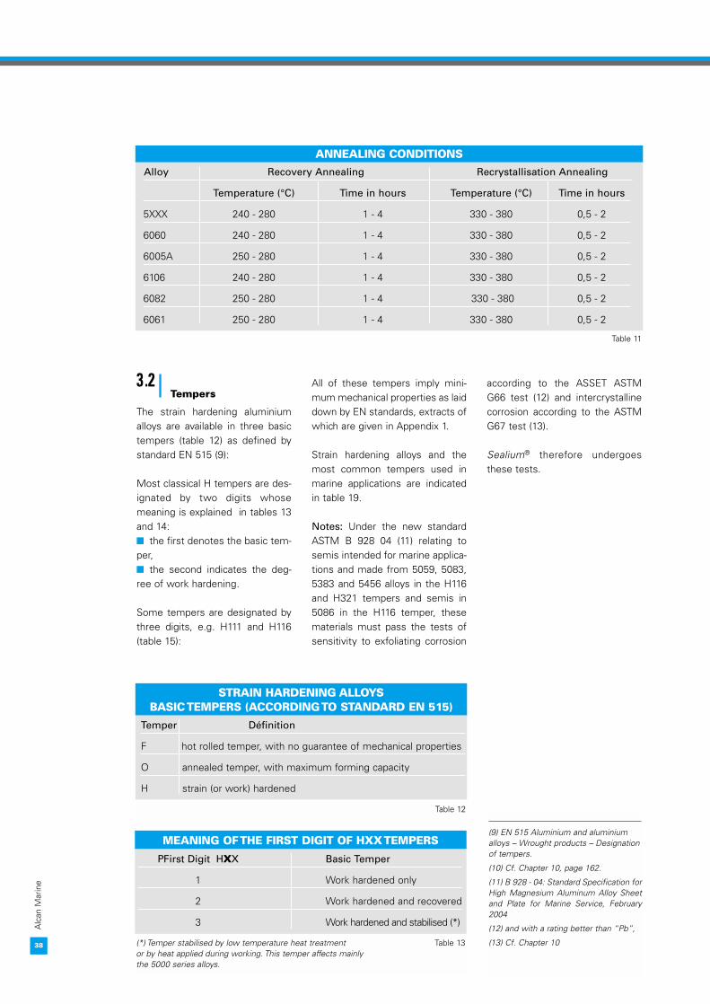
Table 11 lists annealing conditions(treatment temperature, holdingtime) for some alloys.
If it is to retain its good capacity forforming, the annealed metal mustnot present a coarse grain (as indi-cated by the "orange peel" phenom-enon during working operations).
There are a number of require-ments for obtaining an annealedmetal with a fine grain:� The metal must have receiveda sufficient rate of working, cor-responding to a relative reductionin section of at least 15%. If thisrequirement is not met, then themetal must undergo recoveryannealing only (i.e. recrystallisa-tion annealing must be avoided),� The rate of temperature rise mustbe rapid, from 20 to 60°C per hour,� Excessive temperatures,above 350 to 400°C, and exces-sive temperature holding times,i.e. not more than 2 hours, mustbe avoided.
37
Micrographicviews
Har
dnes
s Recovery
Recrystallization
Annealing
Time
A
C
B
D
O
HARDNESS CURVE DURING ANNEALING
Figure 19
(8) Strictly speaking, all metals and alloysstrain harden, but in the metallurgy ofaluminium the term “strain hardening”is restricted to the alloys belonging toseries that cannot age harden.
38
Alc
an M
arin
e
38
STRAIN HARDENING ALLOYS BASIC TEMPERS (ACCORDING TO STANDARD EN 515)
Temper Définition
F hot rolled temper, with no guarantee of mechanical properties
O annealed temper, with maximum forming capacity
H strain (or work) hardened
Table 12
PFirst Digit HXX Basic Temper
1 Work hardened only
2 Work hardened and recovered
3 Work hardened and stabilised (*)
(*) Temper stabilised by low temperature heat treatment Table 13or by heat applied during working. This temper affects mainly the 5000 series alloys.
ANNEALING CONDITIONSAlloy Recovery Annealing Recrystallisation Annealing
Temperature (°C) Time in hours Temperature (°C) Time in hours
5XXX 240 - 280 1 - 4 330 - 380 0,5 - 2
6060 240 - 280 1 - 4 330 - 380 0,5 - 2
6005A 250 - 280 1 - 4 330 - 380 0,5 - 2
6106 240 - 280 1 - 4 330 - 380 0,5 - 2
6082 250 - 280 1 - 4 330 - 380 0,5 - 2
6061 250 - 280 1 - 4 330 - 380 0,5 - 2
Table 11
MEANING OF THE FIRST DIGIT OF HXX TEMPERS(9) EN 515 Aluminium and aluminiumalloys – Wrought products – Designationof tempers.
(10) Cf. Chapter 10, page 162.
(11) B 928 - 04: Standard Specification forHigh Magnesium Aluminum Alloy Sheetand Plate for Marine Service, February2004
(12) and with a rating better than “Pb”,
(13) Cf. Chapter 10
3.2Tempers
The strain hardening aluminiumalloys are available in three basictempers (table 12) as defined bystandard EN 515 (9):
Most classical H tempers are des-ignated by two digits whosemeaning is explained in tables 13and 14:� the first denotes the basic tem-per,� the second indicates the deg-ree of work hardening.
Some tempers are designated bythree digits, e.g. H111 and H116(table 15):
All of these tempers imply mini-mum mechanical properties as laiddown by EN standards, extracts ofwhich are given in Appendix 1.
Strain hardening alloys and themost common tempers used inmarine applications are indicatedin table 19.
Notes: Under the new standardASTM B 928 04 (11) relating tosemis intended for marine applica-tions and made from 5059, 5083,5383 and 5456 alloys in the H116and H321 tempers and semis in5086 in the H116 temper, thesematerials must pass the tests ofsensitivity to exfoliating corrosion
according to the ASSET ASTMG66 test (12) and intercrystallinecorrosion according to the ASTMG67 test (13).
Sealium® therefore undergoesthese tests.

3. ALUMINIUM ALLOYS IN MARINE APPLICATIONS
39
Alc
an M
arin
e
4.AGE HARDENINGALLOYS
These alloys belong to the 2000,6000 and 7000 series.
4.1Principle of age hardening
The maximum mechanical propertiesof these alloys are obtained by heattreatment in 3 stages (figure 20):
� Solution heat treatment is car-ried out at high temperature, inthe region of 530°C for 6000series alloys. While the metal isheld at temperature, the alloy’sconstituents which are in the formof dispersed intermetallics are dis-solved to form a homogeneoussolid solution;
� Quenching is a process of rapidcooling normally obtained byrapidly plunging the metal in coldwater when it leaves the furnace.Extruded Shapes can be “pressquenched” by passing from theexit of the die into a tunnel wherethey are sprayed with fine dropletsof water (14);
� Natural ageing or artificialageing. The quenched metal is in a
metastable state, which meansthat its structure evolves (15) overtime culminating in a stable reor-ganisation in which the alloyingelements are rejected from thesolid solution in the form of veryfine, dispersed precipitates. Thisprecipitation increases the hard-ness of the metal. 39
HXXX TEMPERS (ACCORDING TO STANDARD EN 515)
Temper Characteristics
H111 This temper differs from the O temper in that semis delivered in this temper are roller levelledafter annealing to improve their dimensional characteristics such as flatness.
H112 This temper relates to semis whose level of mechanical properties is acquired by hot working ora limited amount of cold working.
H116 This temper denotes semi-finished products in the 5000 series containing 4% or more ofmagnesium (5083, 5086 etc.). In this temper, the semis must present a defined resistance to exfoliating corrosion in the ASTMG66 test (ASSET test) (10).
HXX4 This temper is used for “tread plate” engraved from the appropriate HXX temper.
MEANING OF THE SECOND DIGIT OF HXX TEMPERS
AGE HARDENING SEQUENCE
Tem
pera
ture
Solution heat treament
Quench Natural ageing (*)
Artificial ageing
TimeTo
To= ambiant temperature
(*) Controlled plastic deformation to obtain T 451 and T 651 is performed between quenching andartificial ageing.
T1
(14) This is common practice with anumber of extrusion alloys in the 6000series (6060, 6005A, 6106) which are“press quenched” by cooling in forcedair or water spray. They are designatedby tempers T1 (press quenched andnaturally aged) and T5 (press quenchedand artificially aged).
(15) Quite rapidly, in a few hours forcertain alloys.
Table 14
Second Digit HXX Meaning Degree of Work Hardening (%)
2 Quarter hard ≈ 12
4 Half hard ≈ 25
6 Three-quarter hard ≈ 50
8 Fully hard ≈ 75
Figure 20
Table 15

40
Alc
an M
arin
e
This phenomenon is known asage hardening. It can take placeat ambient temperature, in whichcase it is referred to as naturalageing. With some alloys, likethose of the 6000 series, theprocess can be accelerated byholding the metal at higher tem-peratures (150 to 190°C), increas-ing its hardness as a result. Thisthermal treatment is performed ina furnace and is known as artifi-cial ageing.
These thermal treatments mustbe carried out under rigorous con-ditions of temperature, time andquench rate, otherwise the finalmechanical properties of themetal and its corrosion resistancemay be affected.
Table 16 and Table 17 list the heattreatment conditions and thesolution treatment times respec-tively for the main alloys of the6000 series used in marine appli-cations
.4.2Softening by annealing
When forming semis made from6000 series alloys, it may be nec-essary to perform intermediateannealing to restore their plastic-
ity. The temperatures and holdingtimes depend on the alloy, and aregiven in table 11, p.38.
After annealing, the rate of coolingmust be controlled to prevent aquenching effect.40
CONDITIONS FOR SOLUTION HEAT TREATMENT, QUENCHING AND ARTIFICIAL AGEING
Alloy Temper Solution Heat Treatment Quench Medium Artificial Ageing Natural ageing Temperature (°C) (1) Temperature (°C) Time (hours) minimum (days)
6060 T4 530 ± 5 Forced air (3) or water 8
T6 530 ± 5 Forced air or water 175 ± 5 8or 185 ± 5 6
6005A T4 530 ± 5 Water ≤ 40°C (3) 8
T6 530 ± 5 Water ≤ 40°C 175 ± 5 (2) 8or 185 ± 5 6
6082 T4 530 ± 5 Water ≤ 40°C (3) 8
T6 530 ± 5 Water ≤ 40°C (3) 165 ± 5 (2) 16or 175 ± 5 8
6061 T4 530 ± 5 Water ≤ 40°C 8
T6 530 ± 5 Water ≤ 40°C 175 ± 5 (2) 8or 185 ± 5 6
(1) The holding time is shown in table 17. Table 16
(2) This treatment produces the optimum mechanical properties associated with the highest values of A %.
(3) because these alloys have a very low critical rate of quench, thin semis can be quenched in forced air.
SOLUTION TREATMENT TIMES
Thickness or Minimum holding time at temperatureDiameter (mm) in air furnace (minutes) (*)
≤ 0,5 20
0,5 - 0,8 25
0,8 - 1,6 30
1,6 - 2,3 35
2,3 - 3,0 40
3,0 - 6,25 50
6,25 - 12,0 60
12,0 - 25,0 90
25,0 - 37,5 120
37,5 - 50 150 (*) This is the minimum holding time at temperature Table 17(according to standard AMS STD-2772).

3. ALUMINIUM ALLOYS IN MARINE APPLICATIONS
41
Alc
an M
arin
e
4.3Designation of tempers
The tempers of age hardeningalloys are all designated by the let-ter T followed by 1 to 5 digits, a fulldescription of which will be foundin standard EN 515 (table 18).
Age hardening alloys and the mostcommon tempers used in marineapplications are indicated intable 19.
41
PRINCIPAL TEMPERS OF AGE HARDENING ALLOYS
This designation is used for sheet, plate, rolled or cold-finished bar, hand or ring forging and rolled ring which,after solution heat treatment or after cooling following hotworking, are stretched by the amount indicated: � plate: 1.5% to 3% permanent set� sheet: 0.5% to 3% permanent setThese products receive no further straightening after
stretching.
Metal in T4 or T6 temper which,after quenching, undergoescontrolled stretching to relieveinternal stresses.
T451
T651
This designation applies to products that undergo no coldworking after solution heat treatment, or in which the effectsof cold working associated with flattening or straightening donot alter the limits of mechanical properties.
Solution heat treated thenartificially aged.
T6
This designation applies to products that undergo no coldworking after the cooling process that follows hot working,or in which the effects of cold working associated withflattening or straightening do not alter the limits ofmechanical properties.
T5 Cooled from an elevatedtemperature shaping process then artificially aged.
T5
This designation applies to products that undergo no coldworking after solution heat treatment, or in which the effectsof cold working associated with flattening or straightening donot alter the limits of mechanical properties.
Solution heat treated and naturally aged to a substantiallystable condition.
T4
This designation is used for products which, after solutionheat treatment, undergo cold working to improve theirstrength, or in which the effects of cold workingassociated with flattening or straightening alters the limitsof mechanical properties.
T3 Solution heat treated, coldworked and naturally aged to asubstantially stable condition.
T3
This designation applies to products that undergo no coldworking after the cooling process that follows hot work-ing, or in which the effects of cold working associatedwith flattening or straightening do not alter the limits ofmechanical properties.
T1 Cooled from an elevated temperature shaping process andnaturally aged to a substantially stable condition.
T1
NotesMeaningNotes
Table 18

42
Alc
an M
arin
e
42
MECHANICAL PROPERTIES FOR SHEET AND STRIP (*)Alloy Thickness (mm) Temper Rm (MPa) Rp0,2 (MPa) A % (**) min
min max min A50 A
5754 3 ≤ t ≤ 50 O/H111 190 240 80 18 17H24 240 165 10 8
5086 3 ≤ t ≤ 50 O/H111 240 310 100 17 163 ≤ t ≤ 12,5 H112 250 125 812,5 ≤ t ≤ 50 H112 240 105
3 ≤ t ≤ 50 H116 275 195 10 93 ≤ t ≤ 50 H32 and H321 275 335 185 10 93 ≤ t ≤ 50 H34 300 235 9 8
5083 3 ≤ t ≤ 50 H32 and H321 305 380 215 10 93 ≤ t ≤ 50 O and H111 275 350 125 16 153 ≤ t ≤ 50 H112 275 125 12 103 ≤ t ≤ 50 H116 305 215 12 10
5383 3 ≤ t ≤ 50 O/H111 290 145 17(19) 3 ≤ t ≤ 50 H116 or H321 305 220 10
(*) Taken from Table 4 of standard EN 13195-1. Table 20
(**) When they are available, values of A50mm must be applied up to (and including) 12.5 mm thick and values of A above 12.5 mm thick.
RECOMMENDED ALLOYS FOR MARINE APPLICATIONS (ACCORDING TO EN 13195-1) (16)Alloy Sheet and Strip Extrusion
Bar Tube Shapes
5754 O/H111 O/H111 O/H111 H112H112
H32, H34, H36
5454 O/H111 O/H111 O/ H111 H112H112 H112 H112
H32, H34
5086 O/H111 O/ H111 O/ H111 H112 H112, H116 (a) H112 H112
H32 (a), H34 (a)
5083 O/H111 O/H111 O/H111 H112and 5383 (17) H112, H116 (a) H112 H112
H32 (a), H34 (a)
6082 O (b) O/H111 (b) O/H111 (b) O/H111 (b)T4, T451 T4 (c) T4 (c), T5 T4 (c)T6, T651 T6 (c) T6 (c) T6 (c)
6106 T6 (c)
6005A T6 (c) T6 (c) T4 (c)T6 (c)
(a) The 5083, 5383 and 5086 alloys made in the H116 temper as sheet, Table 19strip and plate must be tested evaluate their resistance to intergranular and exfoliating corrosion (cf. Chapter 10).
(b) This temper is not intended for any final use. The thermal treatment is applied after forming.
(c) The mechanical properties can be obtained by press quenching.

3. ALUMINIUM ALLOYS IN MARINE APPLICATIONS
43
Alc
an M
arin
e
43
5.THE PRINCIPALALLOYS FORMARINEAPPLICATIONS
Most yards that build ships andequipment for coastal and off-shore installations use the alloysemis as recommended by stan-dard EN 13195-1 (16) from whichtable 19 is taken.
5.1Guaranteedmechanical propertiesat ambienttemperature
In Appendix 1 the reader will findthe mechanical properties guaran-teed by standards EN 485-2 andEN 1386 for tread plate (18).
Where semis are controlled by aclassification society, standard EN13195-1 specifies the minimummechanical properties shown intable 20 and table 21 for rolled andextruded semis respectively.
5.2Mechanical propertiesat low temperatures
Aluminium alloys, particularlythose that belong to the 5000 and6000 series, can be exposed tolow temperatures without suffer-ing any structural alteration (20).
This property accounts for thegrowth in the cryogenic uses ofaluminium, e.g. tanks in methanecarriers (20), exchangers in naturalgas liquefaction and regasificationplants, etc.
Aluminium has also been used inthe construction of a number ofpolar and circumpolar explorationvessels.
The change in the mechanical prop-erties of 5083 O between –196°Cand +200°C are listed in table 22 byway of example. It will be notedthat the capacity for elastic defor-mation does not diminish at cryo-genic temperatures (figure 21).
Prolonged holding at low tempera-tures does not modify the mechan-ical properties following the returnto ambient temperature.
(16) EN 13195-1: Aluminium andaluminium alloys: Wrought products andcastings for marine applications(shipbuilding, maritime and offshore),December 2002, table 1.
(17) Sealium® is always 5383 temperH116 for rolled and temper H112(capable H116) for extruded.
(18) EN 1386. Aluminium and aluminiumalloys – Tread plate – Specifications.
(19) Sealium® is always temper H116.
(20) Unlike steels, aluminium alloys haveno “transition point”, a temperaturebelow which they may sustain a fragilerupture.
Rm
-Rp 0,
2
MPa
A%
Rm
A%
Rp0,2
+ 200 °Temperature °C
Alloy 5086, O Temper
500
400
300
200
100
0
50
40
30
20
10
4.3
5086 O - INFLUENCE OF TEMPERATURE
➤ ➤
Figure 21
- 200 ° 0
ALUMINIUM WATERJET LJ114E

44
Alc
an M
arin
e
44
MECHANICAL PROPERTIES AT TEMPERATURE (*)AFTER HOLDING FOR 10,000 HOURS
Alloy Temper 20°C 100°C 150°C 204°C
Rm Rp0,2 A % Rm Rp0,2 A % Rm Rp0,2 A % Rm Rp0,2 A %
5086 O 262 117 30 262 117 36 200 110 50 152 103 60
5083 O 290 145 25 275 145 36 215 130 50 150 115 60
6082 T6 315 280 12 300 265 14 240 220 17 130 105 28
6061 T6 310 276 17 290 262 18 234 214 20 131 103 28
(*) They are measured at the temperature indicated. Table 23
MECHANICAL PROPERTIES OF EXTRUDED SEMIS (*)
Alloy Form Thickness (mm) Temper Rm Rp0,2 (MPa) A % (**) min
min min A50 A
5086 Shapes, bar, tube 3 ≤ t ≤ 50 H112 240 95 10 12
5083 Shapes, bar, tube 3 ≤ t ≤ 50 H111 270 110 10 12 Shapes, bar, tube 3 ≤ t ≤ 50 O and H112 270 125 10 12
6060 Shapes, bar, tube 3 ≤ t ≤ 25 T5 190 150 12 12Shapes, bar, tube 3 ≤ t ≤ 25 T6 190 150 12 12
6061 Shapes, bar, tube 3 ≤ t ≤ 50 T5 or T6 260 240 10 8 Profilés fermés 3 ≤ t ≤ 50 T5 or T6 245 205 4
6005A Shapes, bar, tube 3 ≤ t ≤ 25 T5 or T6 260 215 8 6 Closed shapes 3 ≤ t ≤ 25 T5 or T6 250 215 5
6082 Shapes, bar, tube 3 ≤ t ≤ 25 T5 or T6 310 260 10 8 Closed shapes 3 ≤ t ≤ 25 T5 or T6 290 240 5
6106 Shapes, bar, tube 3 ≤ t ≤ 25 T6 240 195
(*) Taken from Table 4 of standard EN 13195-1. Table 21
(**) When they are available, values of A50mm must be applied up to (and including) 12.5 mm thick and values of A above 12.5 mm thick.
5083 O CHANGE IN MECHANICAL PROPERTIES (*)
Temperature°C (**) Rm (MPa) Rp0,2 (MPa) A %
– 196 390 140 34
– 80 280 120 26
– 28 270 120 24
+ 20 270 120 22
+ 100 270 120 26
+ 150 210 110 35
+ 200 155 105 45
(*) After 10,000 hours holding at temperature. Table 22
(**) Holding and measurement temperature.

3. ALUMINIUM ALLOYS IN MARINE APPLICATIONS
45
Alc
an M
arin
e
6.A NEW ALLOY:SEALIUM ®,“MARINE GRADE”
Because of the presence of theheat affected zone, a welded alu-minium alloy structure is designedon the basis of the proof stress so
in the annealed condition (O orH111) for strain hardened alloys.
Accordingly, the increase in proofstress in the heat affected zonemeans that for a welded structurewe can either increase unitstresses for the same thicknessof parent metal, or reduce thethickness for the same stress.
A welded joint consists of a weldbead and the heat affected zoneon either side of it, which is itselfconnected to the parent metal(figure 23).
The increase in the mechanicalproperties of the welded jointdepend on that of each of thejoint’s components: the parentmetal, the heat affected zone(HAZ) and the weld bead, as wellas on their metallurgical structure.
Research has shown that the bestresults are obtained with a parentmetal that has a fibrous structureand a recrystallised weld beadwith fine grains [1] (figure 24).
45
5.3Mechanical propertiesat temperaturesabove 100°C
The mechanical properties of alu-minium alloys at temperaturesover 100°C depend on the level ofthe temperature and the holdingtime as shown in figure 22 for the6061. As temperature rises, theultimate tensile strength Rm andyield strength Rp0.2 decrease while
ultimate elongation A% increases.The change in the mechanicalproperties of alloys 5083, 5086,6082 and 6061 are given intable 23.
Hot working these alloys thereforeleads to a significant drop inmechanical properties, especiallyamong 6000 series alloys in the T5or T6 temper.
1
0,8
0,6
0,4
0,2
0
95 150 205 260 315 370
Temperature (°C)* measured after return to ambient
Rm (θ) - Rm (20°C)
Rm (20°C)
Holding time (H)
0,510
1001000
10 000
Figure 22
WELDED JOINT
Weld bead
Base plate
Base plate
HAZ
➤
➤
➤ ➤
➤
Figure 23
6061 T6 – INFLUENCE OF HOLDING TIMES AT TEMPERATURE
OPUS 45

46
Alc
an M
arin
e
To achieve this, it is necessary tocontrol a number of more or lessinterdependent factors that pro-duce a more homogeneous bondbetween the parent metal, theHAZ and the weld bead:� the composition of the alloy:the principal effect of a controlledincrease in the content of magne-sium, zinc and manganese is toraise the level of mechanical pro-perties of the parent metal,
� the metallurgical structure ofeach of the constituents: the addi-tion of zirconium promotes thegrain flow of the parent metal, anda fine grain in the weld bead helpsto improve the level of mechanicalproperties,� the working conditions, optimi-sed to obtain the H116 temper.
Research by the Alcan ResearchCenter (CRV) has led to the devel-opment of Sealium® (MarineGrade) which is 5383 still in theH116 temper. It meets thedemands of constructors lookingfor high-performance alloys.
This new alloy, which is registeredby the Aluminium Associationunder the designation AA5383,has been approved by most of theclassification societies:
� American Bureau of Shipping ABS, � Bureau Veritas BV, � Det Norske Veritas DNV, � Germanischer Lloyd GL, � Lloyd’s Register of Shipping LR, � Nippon Kaiji Kyokai NKK� Registro Italiano Navale RINA.
6.1Mechanical properties
Publications about these newalloys report the following results:� on parent metal as sheet (table 24),� on welded metal (table 25).� on extruded shape (table 26)
Comparative tests have been car-ried out on 6 mm thick sheet in5083 and in Sealium®, butt weldedwith 5183 filler [2].
The mean mechanical properties(five measurements) according tothe DNV report (figure 25) aregiven in table 25.
These results show that on thewelded Sealium®, and in the direc-tion square to the weld, the gain inultimate tensile is 12 MPa and inproof stress 15 MPa comparedwith the 5083, or 4% UTS and11% proof stress. In the heataffected zone the gains are 20.5and 11.6% respectively.
46
MINIMUM MECHANICAL PROPERTIES OF THE PARENT METAL (*) SHEETS
Alloy Temper Rm (MPa) Rp0,2 (MPa) A %
Sealium® (**) 305 220 10
5083 O 275 125 10
H116 305 215 10
(*) Thickness < 20 mm. (**) Sealium® is always temper H116. Table 24
MEAN MECHANICAL PROPERTIES ON WELDED METAL [1] SHEETS
Parent Metal Square to the weld (a) In the weld seam (b) In the heat affected zone (c)
Rp0,2 (MPa) Rm(MPa) A % Rp0,2 (MPa) Rm(MPa) A % Rp0,2 (MPa) Rm(MPa) A %
5083 H116 134 287 12,8 128 271 22,0 141 301 25,2
Sealium® 149 299 10,2 141 279 21,8 170 336 21,3
Gain in % (*) 11,2 4,2 20,5 11,6
(*) compared with 5083. Table 25
STRUCTURE OF WELDED JOINT ON SEALIUM®
Sealium® 5083 H116
Figure 24
MECHANICAL CHARACTERISTICS ON WELD
Transverse (a)
HAZ (c)
Joint (b)
➤
➤
➤
Figure 25

Generally speaking, tests acrossthe weld seam, according to theDNV recommendations, showthat the yield strength Rp0,2 ofSealium® (see note (17) page 43)is always higher than that of 5083H116 (figure 26).
These results have been corrobo-rated by measurements carriedout on welded sheet (using 5183as filler) by a number of shipyards.
6.2Fatigue strength
Tests have shown that the fatiguelimit of butt welded Sealium® isapproximately 20 MPa higher thanthat of 5083, all other things beingequal (figure 27).
6.3Corrosion resistance
Corrosion tests performed accord-ing to the specifications of stan-dard ASTM B928 on over 50 lotsof Sealium® manufactured byAlcan’s Issoire plant have shownthat its corrosion resistance is atleast equivalent to if not betterthan that of 5083 (table 27).
To pass, a lot must be classified N,PA and PB in the ASSET test andthe loss of weight in the NAMLTmust be less than 15 mg.cm-2
(21).
3. ALUMINIUM ALLOYS IN MARINE APPLICATIONS
47
Alc
anM
arin
e
47
MINIMUM MECHANICAL PROPERTIES ON EXTRUDED SHAPES
Alloy Temper Rm (MPa) Rp0,2 (MPa) A %
Sealium® H112 310 190 12
5083 O 270 110 14 H112 270 125 12
Table 26
ä
ä
Rm (MPa)
Rp0,2
330
310
290
120 130 140 150 160 170 180
MECHANICAL CHARACTERISTICS OF BUTT WELDED SEALIUM®
Sealium® 5083 H116
FATIGUE STRENGTH OF SEALIUM®
210
190
170
150
130
105 106 107
Number of cycles to failure
Sealium®: 6 mm 5083 H116: 6 mm
Rm (MPa)
ä
Figure 27
Figure 26
(21) Cf. Section 11 of Chapter 10.
RESISTANCE TO CORROSION OF SEALIUM®
Exfoliating Corrosion Intercrystalline Corrosion ASSET ASTM G66 Test Test ASTM G67 NAMLT
Sealium® 5083 Sealium® 5083
Parent metal N/PA PA/PB 4 mg.cm-2 4 mg.cm-2
Heat affected zone PA PB
Table 27

48
Alc
an M
arin
e
7.THE SERIES OFCASTING ALLOYS
There are 5 series of industrialcasting alloys (table 28). Like thewrought alloys, casting alloyshave a 5 digit numerical designa-tion according to standard EN1706 (22). Their tempers areshown in table 29.
The potential offered by castingprocesses - especially for the cre-ation of relatively complex shapes -makes it possible to use aluminiumcasting alloys in numerous marineapplications. These include:� ships’ superstructures,� structural components,� assembly nodes,� components for assemblieswith mechanical functions,� interior fitments,� various supports.
The alloys used for these marineapplications are first melt alloys,and belong almost exclusively totwo series:
� the 40000 series comprisingaluminium-silicon alloys, and� the 50000 series comprisingaluminium-magnesium alloys.
Aluminium-copper alloys must beavoided for marine applicationsunless they are well protected.
7.1The silicon alloys of the 40000 series
These alloys have:� excellent potential for casting,making it possible to easily designsound components with complexshapes,� very good weldability (23),� very good mechanical proper-ties after thermal treatment for theage hardened alloys that containmagnesium (24),� very good behaviour in marineenvironments.
Four alloys in particular are recom-mended:� 41000 for components requiredto present a good appearanceafter mechanical polishing andanodising,� 42100 and 42200 for complexcomponents required to have highmechanical properties. These twoalloys must be age hardened inorder to present good mechanicalproperties, � 44100 for slender chill-castcomponents.
7.2The magnesium alloysof the 50000 series
The aluminium-magnesium alloysare particularly notable for their:� excellent aspect after mechani-cal polishing,� eminent suitability for anodi-sing for protection and decorativepurposes,� good weldability: they can bejoined to other cast, rolled or extru-ded products of similar composi-tion,� excellent resistance to corro-sion in marine environments. Theyare all ideally suited to marineapplications, but two alloys in par-ticular are recommended:
� 51100, with 3% magnesium,� 51300, with 6% magnesium.
48
Alloying Element Designation
None 10000
Copper 20000
Silicon 40000
Magnesium 50000
Zinc 70000
Table 28
TEMPERS OF CASTING ALLOYS
Principal Thermal Treatments EN 1706 AFNOR NF A 57 702 (*)
None, as-cast F Y 20 Y 30
Solution heat treatment, quenching and natural ageing T4 Y 24 Y 34
Solution heat treated, quenched and artificially aged to peak strength T6 (**) Y 23 Y 33
Solution heat treated, quenched and under-aged T64 Y 23 Y 33
(*) Y2X denotes sand cast, Y3X denotes chill cast. (**) In practice the artificially aged T6 is never at peak strength Table 29but is always just below it to retain a minimum of elongation. T64 denotes an under-aged temper designed to promote elongation.
SERIES OF CASTING ALLOYS
(22) EN 1706. Aluminium and aluminiumalloys. Chemical composition andmechanical properties.
(23) It is not advisable to weld 40000series casting alloys to 5000 serieswrought alloys (and vice versa. (Cf. Chapter 6).
(24) The age hardening process for the42100 and 42200 alloys is as follows:solution heat treatment for 10 h at540 °C, water quenching then artificiallyageing for 6 h at 160°C; the process forthe 41000 is the same except: solutionheat treatment for 4 h at 540°C.

3. ALUMINIUM ALLOYS IN MARINE APPLICATIONS
49
Alc
an M
arin
e
8.1Chemicalcomposition
The chemical composition in com-ponents according to EN 1706 isgiven in table 30.
8.PROPERTIES OFCASTING ALLOYS
The principal properties of thecasting alloys used in marineapplications are shown in thetables below.
STANDARD COMPOSITION IN COMPONENTS (% BY WEIGHT)
Alloy Si Fe Cu Mn Mg Ni Zn Ti Pb Sn
41000 1,6 0,30 0,45 0,052,4 0,60 0,10 0,50 0,65 0,05 0,10 0,20 0,05 0,05
42100 6,5 0,25 0,087,5 0,19 0,05 0,10 0,45 0,07 0,25
42200 6,5 0,45 0,087,5 0,19 0,05 0,10 0,70 0,07 0,25
44100 10,513,5 0,65 0,15 0,55 0,10 0,10 0,15 0,20 0,10 0,05
51100 2,50,55 0,55 0,05 0,45 3,5 0,10 0,20
51300 4,50,55 0,55 0,10 0,45 6,5 0,10 0,20
Note: Where a single value is given, it corresponds to the permitted maximum. Table 30
PHYSICAL PROPERTIES OF CASTING ALLOYS
Alloys Density Thermal Conductivity Coefficient of linear Solidification Mean (kg.m-3) at 20°C Expansion between Interval Contraction
(W.m-1°C-1) 20 and 100°C °C (%)
41000 2700 160 22.10-6
640-555 14
42100 2680 160 21,5.10-6
615-555 12,5
42200 2680 160 21,5.10-6
615-555 12,5
44100 2650 165 20.10-6
580-575 11
51100 2670 145 24.10-6
640-590 14
51300 2640 125 24.10-6
625-540 13
Table 31
8.2Physical properties
GUINDEAU 312

50
Alc
an M
arin
e
ENGENEERING SUITABILITY OF CASTING ALLOYS
Alloy Casting Cracks Thin Dimensional Machinability Weldability Polishing Anodizing Anodizing Resistance toSensibility Pieces Stability (TIG and for for Corrosion in
MIG arc) Protection Decoration marine environment
41000 2 2 2 3 3 3 4 4 4 3
42100 3 3 4 3 2 3 3 4 0 3
42200 3 3 4 2 3 3 3 4 0 3
44100 4 4 4 4 1 4 2 4 0 3
51100 2 1 1 3 4 4 4 4 4 4
51300 2 1 2 3 4 4 4 4 3 4
0 - Unsuitable. 1 - Poor. 2 - Fair. 3 - Good. 4 - Excellent. Table 32
Alloy Temper Cast Mode Rm (MPa) Rp0,2 (Mpa) A %
41000 T6 Y23 240 180 3 Y33 260 180 5
42100 T6 Y23 230 190 2 Y33 290 210 4
42200 T6 Y23 250 210 1 Y33 320 240 3
44100 F Y20 150 70 4 Y30 170 80 5
51000 F Y20 140 70 3 Y30 150 70 5
51300 F Y20 160 90 3 Y30 180 100 4
Table 33
8.3Engineeringsuitability
8.4Mechanicalproperties
Bibliography[1] “High Strength Marine GradeAluminium Alloys: a new generation of5383 with improved properties”, C. HÉNON,R. DIF, A. DURAN, 18th Fast FerryConference and Exhibition, Nice, France,February 2002.
[2] The potential of 5383 alloy in marineapplication. G. M. RAYNAUD AND
PH GOMIERO, Pechiney Rhenalu,Conférence Alumitech 97, pp. 353-366.
MECANICAL CHARACTERISTICS ON CAST SAMPLES

3. ALUMINIUM ALLOYS IN MARINE APPLICATIONS
51
Alc
an M
arin
e
ENGINE ROOM OF THE AQUASTRADA TMV 115

52
Alc
an M
arin
e
CATAMARAN UAI 50