alarm install introduction...such as trigger reversal, starter interrupt, add domelights to flashing...
TRANSCRIPT


Local (770)-942-9876 Tech Fax (770)-942-5400
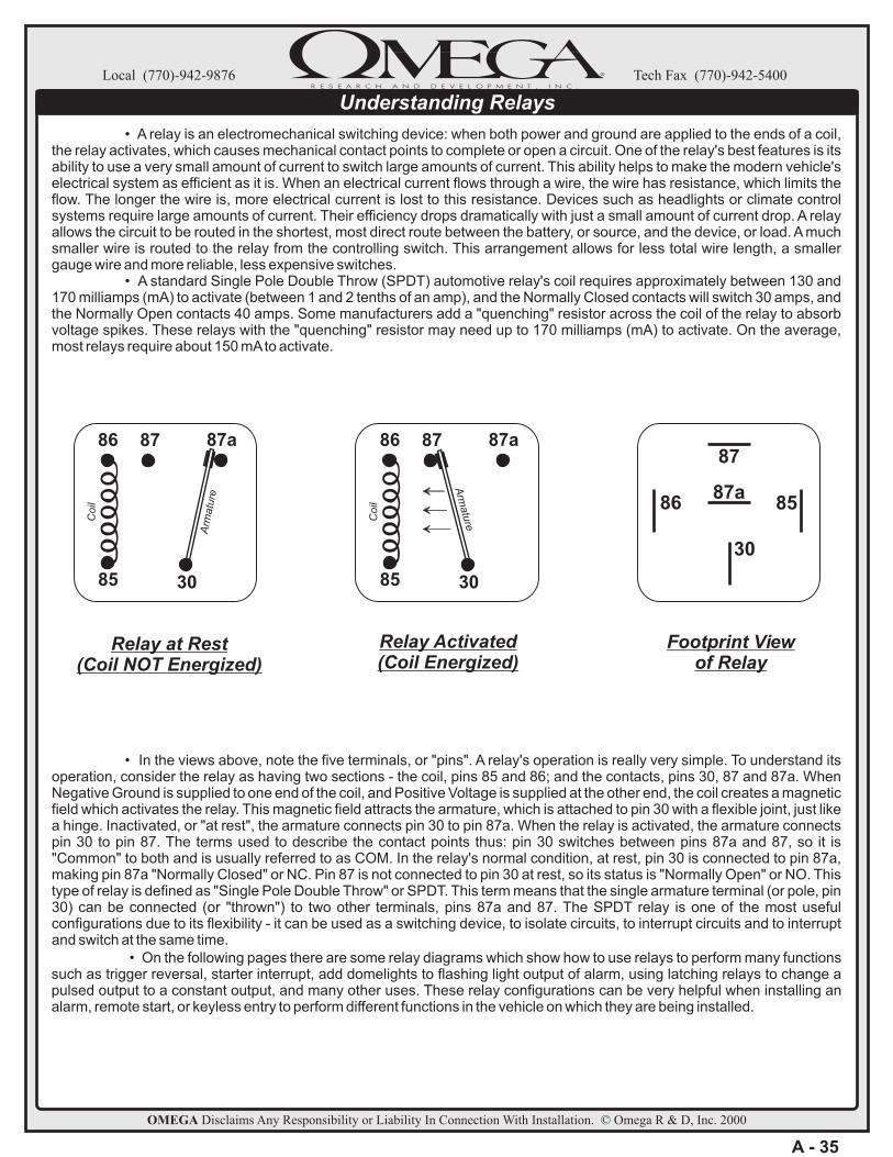
• In the views above, note the five terminals, or "pins". A relay's operation is really very simple. To understand its operation, consider the relay as having two sections - the coil, pins 85 and 86; and the contacts, pins 30, 87 and 87a. When Negative Ground is supplied to one end of the coil, and Positive Voltage is supplied at the other end, the coil creates a magnetic field which activates the relay. This magnetic field attracts the armature, which is attached to pin 30 with a flexible joint, just like a hinge. Inactivated, or "at rest", the armature connects pin 30 to pin 87a. When the relay is activated, the armature connects pin 30 to pin 87. The terms used to describe the contact points thus: pin 30 switches between pins 87a and 87, so it is "Common" to both and is usually referred to as COM. In the relay's normal condition, at rest, pin 30 is connected to pin 87a, making pin 87a "Normally Closed" or NC. Pin 87 is not connected to pin 30 at rest, so its status is "Normally Open" or NO. This type of relay is defined as "Single Pole Double Throw" or SPDT. This term means that the single armature terminal (or pole, pin 30) can be connected (or "thrown") to two other terminals, pins 87a and 87. The SPDT relay is one of the most useful configurations due to its flexibility - it can be used as a switching device, to isolate circuits, to interrupt circuits and to interrupt and switch at the same time.
87
87a
30
8586
87 87a
3085
86
Arm
atu
re
Co
il
87 87a
3085
86A
rmatu
reCo
il
Relay at Rest(Coil NOT Energized)
Relay Activated(Coil Energized)
Footprint View of Relay
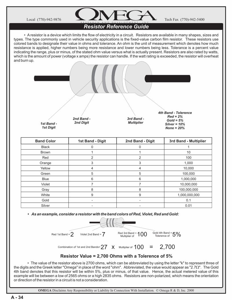
• A relay is an electromechanical switching device: when both power and ground are applied to the ends of a coil, the relay activates, which causes mechanical contact points to complete or open a circuit. One of the relay's best features is its ability to use a very small amount of current to switch large amounts of current. This ability helps to make the modern vehicle's electrical system as efficient as it is. When an electrical current flows through a wire, the wire has resistance, which limits the flow. The longer the wire is, more electrical current is lost to this resistance. Devices such as headlights or climate control systems require large amounts of current. Their efficiency drops dramatically with just a small amount of current drop. A relay allows the circuit to be routed in the shortest, most direct route between the battery, or source, and the device, or load. A much smaller wire is routed to the relay from the controlling switch. This arrangement allows for less total wire length, a smaller gauge wire and more reliable, less expensive switches.
• A standard Single Pole Double Throw (SPDT) automotive relay's coil requires approximately between 130 and 170 milliamps (mA) to activate (between 1 and 2 tenths of an amp), and the Normally Closed contacts will switch 30 amps, and the Normally Open contacts 40 amps. Some manufacturers add a "quenching" resistor across the coil of the relay to absorb voltage spikes. These relays with the "quenching" resistor may need up to 170 milliamps (mA) to activate. On the average, most relays require about 150 mA to activate.
• On the following pages there are some relay diagrams which show how to use relays to perform many functions such as trigger reversal, starter interrupt, add domelights to flashing light output of alarm, using latching relays to change a pulsed output to a constant output, and many other uses. These relay configurations can be very helpful when installing an alarm, remote start, or keyless entry to perform different functions in the vehicle on which they are being installed.
Understanding Relays
OMEGA Disclaims Any Responsibility or Liability In Connection With Installation. © Omega R & D, Inc. 2000
A - 35
Local (770)-942-9876 Tech Fax (770)-942-5400
Change (-) Negative to (+) Positive Change (+) Positive to (-) Negative
87
87a
30
8586
Constant 12 volts +
Constant 12 volts +
(-) Negative Trigger to bechanged to Positive
(+) Positive Output
87
87a
30
8586
(+) Positive Trigger to bechanged to Negative
(-) Negative Output
Chassis Ground
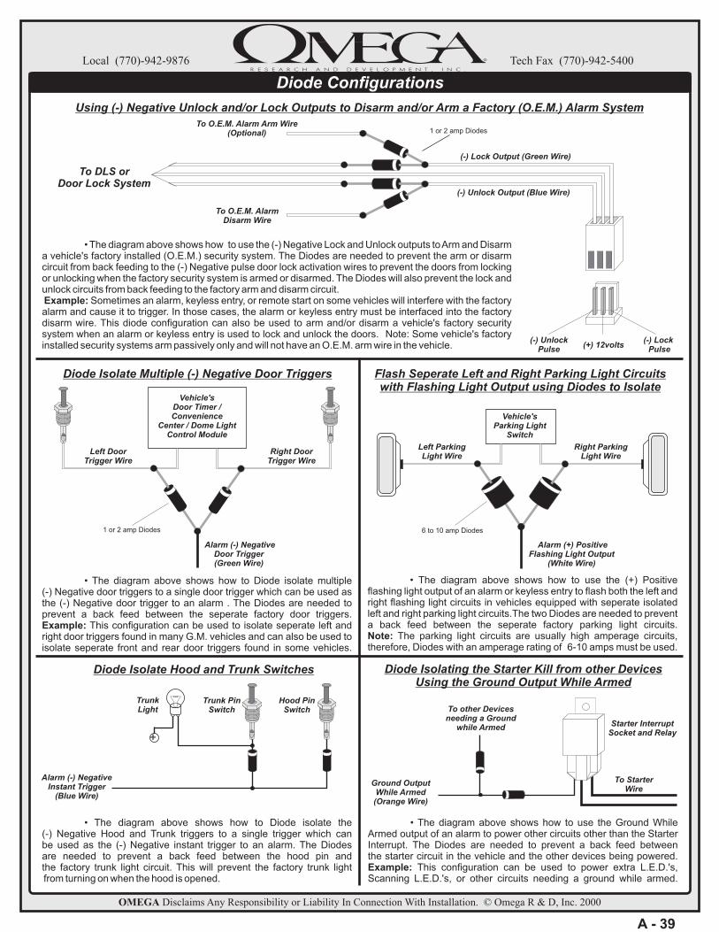
• The diagram above shows how to change a (-) Negative Pulse to (+) Positive using one Single Pole Double Throw (SPDT) relay. Example: This relay configuration can be used to change the (-) Negative door lock outputs of an alarm to Positive for a Positive door lock circuit, or to change the (-) Trunk release output to Positive for a Positive Trunk release circuit. This configuration can also be used to change a vehicle's (-) Negative circuit to (+) Positive for use by the alarm.
• The diagram above shows how to change a (+) Positive Pulse to (-) Negative using one Single Pole Double Throw (SPDT) relay. Example: This configuration can be used to change a Positive siren output to (-) Negative for use on a vehicle's Horn circuit, to change an alarm's Positive flashing light output to Negative for use on vehicle's which require a Negative Pulse to operate the parking lights, or can be used to change a vehicle's Positive door trigger to (-) Negative.
Change small Amperage (+) Positive to Stronger (+) Positive Output
87
87a
30
8586
Ground
(+) Positive Trigger to be "stepped-up" to a
stronger (+) Positive Output
High Amperage (+) Positive Output
Constant 12 volts
+
Change small Amperage (-) Negative to Chassis Ground
87
87a
30
8586
Constant 12 volts
+
Ground(-) Negative Trigger to
be "stepped-up" to Chassis Ground
Chassis Ground Output
• The diagram above shows how to change a small Amperage (-) Negative Pulse output to a Chassis Ground Pulseoutput using one Single Pole Double Throw (SPDT) relay.Example: This configuration can be used to "step-up" the 250 ma.(-) Negative door lock, trunk release, 3rd channel, or starter interrupt outputs of the alarm to operate circuits which require chassis ground, or to "step-up" the ground to be able to operate more circuits.
Chirp Siren from (-) Negative Pre-warning output of Dual Zone Sensor
87
87a
30
8586
(-) Negative Pre-Warning output from Sensor
(Green Wire)
Positive input to Siren (Red Wire)
Positive Siren output fromalarm (Brown Wire)
• The diagram above shows how to use the (-) NegativePre-Warning output of a Dual Zone Sensor in conjunction with a Single Pole Double Throw (SPDT) relay, and a 1 or 2 Amp Diode, to pulsethe siren of an alarm in the event of a Pre-Warning intrusion.Example: This configuration can be used to add a single audible Pre-Warning chirp to an alarm which does not offer a 4-Pin Auxiliary input or an alarm which does not offer any Pre-Warning input.
• The diagram above shows how to use the ground while armed Starter Interrupt output (Orange Wire) with one Single Pole Double Throw (SPDT) relay to activate a Starter Interrupt with an alarm. Example: This configuration can be used to prevent a vehicle from being started anytime the alarm is armed. Notice that the starter wire in the vehicle must be cut to splice in the relay. The Diode is connected across the relay coil to prevent any kind of "inductive lockup".
• The diagram above shows how to change a small Amperage (+) Positive Pulse output to a stronger, high Amperage Positive Pulse output using one Single Pole Double Throw (SPDT) relay. Example: This configuration can be used to "step-up" the siren output of an alarm to power extra sirens. This configuration can also be used to "step-up" the flashing light output of an alarm to a stronger amperage to flash the headlights in the vehicle instead of the parking lights.
Starter Interrupt
87
87a
30
8586
Cut Starter Wire
Starter Interrupt output (Orange Wire) from alarm
To Starter SolenoidTo Ignition Switch
1 or 2 Amp Diode
1 or 2 Amp Diode
Relay Configurations
OMEGA Disclaims Any Responsibility or Liability In Connection With Installation. © Omega R & D, Inc. 2000
A - 36

Local (770)-942-9876 Tech Fax (770)-942-5400
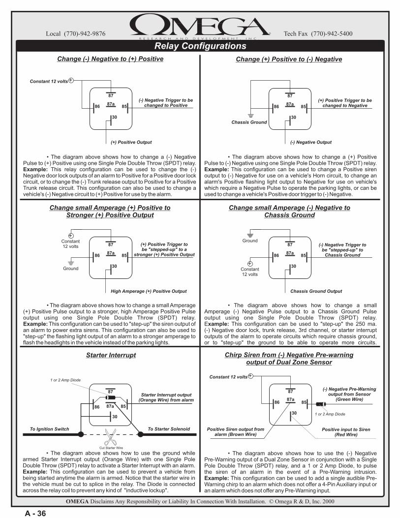
• The diagram above shows how to change a single (-) Negative Pulse to a constant chassis ground output using one Single Pole Double Throw (SPDT) relay and a 1 or 2 amp Diode. Example: This relay configuration can be used to change a single (-) pulse to a constant ground for use with window roll-ups, extra lighting, radio accessories or any other circuit which requires a constant ground instead of one single (-) Negative pulse. Warning: Once the relay is latched it will stay latched until it is reset by opening the Constant 12 volt circuit to pin #86. The Constant 12 volt input to pin #86 can be "opened" or interrupted using a momentary contact switch, or a relay can be added to the 12 volt input to pin #86 and configured as a normally closed circuit so that, when the relay energizes, it will interrupt the 12 volt input and unlatch the "Latching Relay".
• The diagram above shows how to use a couple of Single Pole Double Throw (SPDT) relays to add Domelight Supervision and Flashing Light output to the Flashing Light output (White Wire) of an alarm, on a vehicle with (-) Negative Door Triggers. Example: This relay configuration can be used to add Domelight Supervision to an alarm which does not offer the feature. When adding Domelight Supervision to the Flashing Light output of an alarm, the interior light flashes the same as the Parking lights in the vehicle, therefore, staying on for 60 or 30 seconds after remote disarm.
• The diagram above shows how to use a couple of Single Pole Double Throw (SPDT) relays to add Domelight Supervision and Flashing Light output to the Flashing Light output (White Wire) ofan alarm, on a vehicle with (+) Positive Door Triggers.Example: This relay configuration can be u sed to add Domelight Supervision to an alarm which does not offer the feature. When adding Domelight Supervision to the Flashing Light output of an alarm, the interior light flashes the same as the Parking lights in the vehicle, therefore, staying on for 60 or 30 seconds after remote disarm.
• The diagram above shows how to change a single (+) Positive Pulse to a constant 12 volt output using one Single Pole Double Throw (SPDT) relay and a 1 or 2 amp Diode.Example: This relay configuration can be used to change a single(+) pulse to a constant 12 volt for use with circuits such as extra lighting, radio accessory circuits, or any other circuit which requires a constant 12 volt output instead of one single (+) Positive pulse.Warning: Once the relay is latched it will stay latched until it is reset by opening the ground circuit to pin #86. The ground input to pin #86 can be "opened" or interrupted using a momentary contact switch, or a relay can be added to the ground input to pin #86 and configured as a normally closed circuit so that, when the relay energizes, it will interrupt the ground input and unlatch the "Latching Relay".
Flashing Lights and Dome Light Supervision fromFlashing Light output with (-) Door Trigger
Constant 12 volts
Ground
87
87a
30
8586
87
87a
30
8586
+
(-) Negative Door Trigger(Green Wire) from Alarm
(+) Flashing Light output(White Wire) from Alarm
(+) Positive output toFlashing Lights
Connect to (-) Door Pin Trigger in Vehicle
Flashing Lights and Dome Light Supervision fromFlashing Light output with (+) Door Trigger
Ground
87
87a
30
8586
87
87a
30
8586
Constant 12 volts
+
Constant 12 volts
+(+) Positive Door Trigger(Violet Wire) from Alarm
(+) Flashing Light output(White Wire) from Alarm
(+) Positive output toFlashing Lights
Connect to (+) Door Pin Trigger in Vehicle
Constant 12 volts
Ground
87
87a
30
8586
1 or 2 Amp Diode
Latching Relay (-) Negative Trigger
Reset Switch
+
(-) Negative Pulse Trigger
Constant Chassis Ground Output
Ground
87
87a 8586
1 or 2 Amp Diode
Latching Relay (+) Positive Trigger
Reset Switch
30
Constant 12 volts
+
(+) Positive Pulse Trigger
Constant 12 volt Output
Relay Configurations
OMEGA Disclaims Any Responsibility or Liability In Connection With Installation. © Omega R & D, Inc. 2000
A - 37