alarmline digital linear temperature detection · kidde fire protection or an authorised...
TRANSCRIPT

59812-213 - Revision 3 Page 1 Prelims
ALARMLINE DIGITAL LINEAR TEMPERATURE
DETECTION
MANUAL NO. 59812-213
January 2007
LICO Electronics GmbH
Klederinger Straße 31, A-2320 Kledering / Wien
0043 (0) 1 706 43 00-0, Fax: 0043 (0) 1 706 41 31 www.mess-regeltechnik.at

59812-213 - Revision 3 Page 2 Prelims
PROPRIETARY RIGHTS NOTICE
This document and the information that it contains are the property of Kidde Products Ltd. Rights to duplicate or otherwise copy this document and rights to disclose the document and the information that it contains to others and the right to use the information contained therein may be acquired only by written permission signed by a duly authorised officer of Kidde Products Ltd.
Copyright 2007 Kidde Products Ltd

59812-213 - Revision 3 Page 3 Prelims
Preliminary Pages
AMENDMENT INCORPORATION RECORD
Amendment
Number
Brief Description of Content
Name of Person Incorporating Amendment
1
Cable ref. H8069. Change of min/max alarm temps. Min 178°C Max 190°C
BK
2
1. Part Numbers changed 2. Alarm temperatures changed 3. Application drawings added
BK
3
Various revisions
BK
4
5
6
7
8
9
10
59812-213 - Revision 3 Page 4 Prelims
CAUTION ANTISTATIC PRECAUTIONS
WHEN HANDLING ANY ELECTRIC COMPONENTS OR CIRCUIT BOARDS ANTISTATIC PRECAUTIONS MUST BE CARRIED OUT. FAILURE TO DO SO MAY RESULT IN COMPONENT DAMAGE. Static discharge can be reduced by adhering to the following guidelines. 1. Always use conductive or anti-static containers for transportation and storage, if
returning any item. 2. Wear an earthed wrist strap while handling devices and ensure a good earth is
maintained throughout. 3. Never subject a static sensitive device to sliding movement over an unearthed surface
and avoid any direct contact with the pins or connections. 4. Avoid placing sensitive devices onto plastic or vinyl surfaces. 5. Minimise the handling of sensitive devices and PCBs.

59812-213 - Revision 3 Page 5 Prelims
TABLE OF CONTENTS
Page 1. INTRODUCTION 7
1.1 INTRODUCTION 7
1.2 SPECIFICATION 7
2. OPERATION 9
2.1 OPERATION 9
2.2 TECHNICAL SPECIFICATION 10 3. APPLICATIONS 11
3.1 TYPICAL APPLICATIONS 11 3.2 CONVEYOR BELT FIRE DETECTION 14 3.3 CABLE TRAYS AND RACKS 16 3.4 FLOATING ROOF FUEL STORAGE TANKS 19 3.5 DUST COLLECTOR AND HEAT DRIERS 25
3.6 RACK STORAGE 26
3.7 FREEZER WAREHOUSE 28
3.8 TOXIC OR FUEL WASTE DRUM STORAGE 29
3.9 POWER DISTRIBUTION EQUIPMENT 31
3.10 ESCALATORS 32

59812-213 - Revision 3 Page 6 Prelims
TABLE OF CONTENTS
Page 4. SENSOR CABLE SELECTION 33
4.1 STANDARD SENSOR CABLES H8040 & H8045 33
4.2 STANDARD SENSOR CABLES H8040N & H8045N 33 4.3 SENSOR CABLES H8028, H8069 & H9650 33 5. INSTALLATION 35
5.1 INSTALLATION OVERVIEW 35
5.2 JOINTING 35
5.3 HAZARDOUS AREAS 38
5.4 CABLE FIXINGS 39 6. COMMISSIONING & TEST PROCEDURE 43
6.1 PASSIVE CHECKS 43 6.2 TEST PROCEDURE 44

59812-213 - Revision 3 Page 7 Chapter 1
CHAPTER 1
INTRODUCTION 1.1 Introduction Alarmline Digital sensor cable provides a flexible durable and cost-effective form of fire detection, within a wide range of commercial and industrial fire and overheat risks. Alarmline Digital sensor cable can provide general space protection as well as detection at the point of risk. A wide range of coatings and installation fixings ensure system design and installation is specific to the risk. It is especially suitable for confined areas or harsh environments, which prohibit the use of other forms of detection. It is important to select the cable which is the most appropriate for the application. Alarmline Digital sensor cable and associated controls allow full integration with central fire control panels and extinguishing systems. Alarmline Digital sensor cable provides protection over a wide range of applications. The following application descriptions are typical installations to illustrate the diversity of the product range. If you require further advice regarding Alarmline applications, please consult Kidde Fire Protection or an authorised distributor. 1.2 Alarmline Digital Linear Temperature Detection Specification Cable installation must be in accordance with manufacturers application and installation manuals according to the application being considered. As a variance exists on most applications it is recommended that the manufacturer’s guidance is sought for each project. Consideration shall be made of the following:
- nature of risk - max. ambient temperature - risk of mechanical damage - location of display & controls - requirement for Zener Barriers/Galvanic isolators - interface to other fire alarm or extinguishing systems

59812-213 - Revision 3 Page 8 Chapter 1
Alarmline Digital cable shall have a range of cables capable of operating with the following ambient temperature ranges:
Kidde Fire Protection
Part Number
Ref. No. Maximum Ambient
(°C)
Minimum Alarm (°C)
Maximum Alarm (°C)
Appropriate Detection time (small flame) (sec)
Application
D5387-068 H8040 45 63 70 4 Internal only D5387-368 H8040N 45 63 70 4 Internal/External D5387-085 H8045 45 79 95 5 Internal only D5387-385 H8045N 45 79 95 5 Internal/External D5387-105 H8028 70 101 108 10 Internal/External D5387-174 H8069 105 177 189 20 Internal/External D5387-227 H9650 200 229 251 20 Internal/External
External applications shall use PVC, Fluoropolymer or Polyethylene with Nylon oversheath. Chemical or petrochemical applications shall use Fluoropolymer cable, Part No. D5387-227 or Nylon oversheathed cables, Part Nos. D5387-368 & D5387-385. Alarmline digital cables shall be connected directly to a conventional fire alarm control panel or addressable panel via an appropriate interface. Hazard Area applications shall use suitable Zener Barriers or Galvanic Isolators. Installation The installation method shall be as recommended in the manufacturer’s installation manual and be in accordance with site and environmental requirements. Clips and fittings shall be as recommended in the manufacturers installation manual and match site and environmental conditions. Commissioning Alarmline cable shall be installed with a 1 meter test length of cable that can be heated to its alarm temperature set point in accordance with manufacturers recommendations. Approvals Alarmline Digital cables shall be approved by one or more of the following approval bodies:
- FM Global - UK Power Generation Authorities - CEA European Approval Testing - Chinese Approval (Shenyang)

59812-213 - Revision 3 Page 9 Chapter 2
CHAPTER 2
OPERATION 2.1 Operation Alarmline Digital consists of a range of seven cables designed to operate at a pre-set temperature range. Each cable consists of 2 inner cores of tinned copper over steel, with temperature sensitive insulation. An outer sheath retains the 2 inner cores and provides a degree of mechanical protection. System operation is achieved when the temperature sensitive insulation melts at a pre-determined temperature, allowing the internal conductors to short circuit.
PERFORMANCE CHARACTERISTICS TABLE 2.1 Kidde Part No.
Cable ref.
Protection Colour MaximumAmbient (°C)
Minimum Alarm (°C)
Maximum Alarm (°C)
Suitability
D5387-068
H8040 Polythene Braid
Red/Green 45 63 70 Internal
D5387-368
H8040N Nylon Black 45 63 70 Internal/ External
D5387-085
H8045 Polythene Braid
Red/Black 45 79 95 Internal
D5387-385
H8045N Nylon Black 45 79 95 Internal/ External
D5387-105
H8028 PVC Black 70 101 108 Internal/ External
D5387-174
H8069 PVC Red 105 177 189 Internal/ External
D5387-227
H9650 Fluoropolymer White 200 229 251 Internal/ External
59812-213 - Revision 3 Page 10 Chapter 3
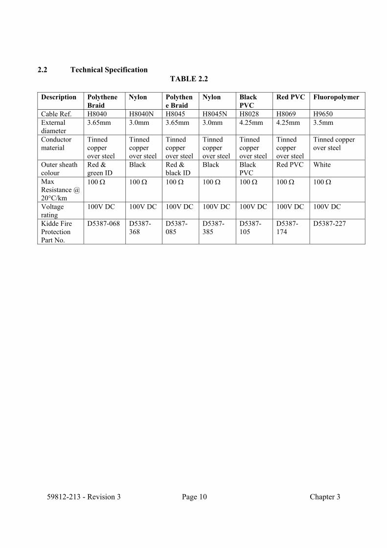
2.2 Technical Specification
TABLE 2.2 Description Polythene
Braid Nylon Polythen
e Braid Nylon Black
PVC Red PVC Fluoropolymer
Cable Ref. H8040 H8040N H8045 H8045N H8028 H8069 H9650 External diameter
3.65mm 3.0mm 3.65mm 3.0mm 4.25mm 4.25mm 3.5mm
Conductor material
Tinned copper over steel
Tinned copper over steel
Tinned copper over steel
Tinned copper over steel
Tinned copper over steel
Tinned copper over steel
Tinned copper over steel
Outer sheath colour
Red & green ID
Black Red & black ID
Black Black PVC
Red PVC White
Max Resistance @ 20°C/km
100 Ω 100 Ω 100 Ω 100 Ω 100 Ω 100 Ω 100 Ω
Voltage rating
100V DC 100V DC 100V DC 100V DC 100V DC 100V DC 100V DC
Kidde Fire Protection Part No.
D5387-068 D5387-368
D5387-085
D5387-385
D5387-105
D5387-174
D5387-227

59812-213 - Revision 3 Page 11 Chapter 1
CHAPTER 3
APPLICATIONS
Alarmline Digital sensor cable has been successfully installed in a wide range of applications. The following are typical examples: 3.1 Typical Applications Electricity Generating Authorities: Cable trays and risers (power control cables).
Boiler front - burner protection. Conveyors - bearing overheat. Transformers. Control room and computer suites - floor voids. Cooling towers. Alternator pits.
Wire Manufacturers: Control cubicle protection. Ships and shipyards: Construction - steelwork/wooden supports.
Ducting and pipework. Control cubicles. Radar. Missile storage.
Marine: "Cocooned" ships.
Engine bay protection - leisure craft. Petro-chemical: On-shore: Ethylene "sphere" storage.
Storage tanks - floating roofs. Cable trays and road tanker protection.
Off -shore: Well heads and cable trays.
Gas Supply Utilities: Power units and pumps. Supermarkets: Cold storage warehousing. Hospitals: Service ducts.

59812-213 - Revision 3 Page 12 Chapter 3
Rubber grinding plant: Dust extraction duct. Aluminium works: Cable trays, mixers and conveyors. Computer suites: Ceiling, floor voids, control cubicles and power supplies. Steel works: Covered conveyor protection, cable trays and storage racks. Grain dryers and storage: Silos and dryers. Water authorities: Cable tunnel and switchgear. Resin plant: Storage tank. Automatic pumping stations: Transformer bay and cable ducts. Coal mills: Pipework carrying coal dust to boilers. Local government authorities: Road tunnels and land fills. Cottages: Thatched roofs. Motor part manufacturers: Gas fired drying conveyor oven.
Paint storage. Chemical plants: Reactor vessels. Ducting manufacturers: Extraction and ventilation systems. Plastic coating process plant: "Dip" tank protection. Timber yards: Bearings - machine shop. Government departments: High rack storage. Semiconductor manufacture: Wet bench applications.

59812-213 - Revision 3 Page 13 Chapter 3
Airports: Passenger walkways, hangars, duty free goods storage Baggage conveyors.
Escalators (bearing overheat monitoring and dust collecting trays).
Service subways. Cold storage plants: Warehouse and power house - water boxes. Forklift truck (overnight charging): Battery box overheat protection. Heating units: Oil pipe temperature monitoring. Power plant: Conveyors. Cereal plant: Freezing chamber - high rack food storage. Sugar refinery: Sugar conveyors. Electronic component manufacturers: Storage racks. Rail authorities: Underground railway tunnels, stations and escalators.
Rolling stock: Flexible couplings and exhaust manifolds.
Industrial kitchens: Canopy protection. Nuclear power authority: Laboratory test equipment - PCB component overheat. Car Parks (Underground & Multi-storey): Area protection. Tank Farms: Rim Seal Protection Fixed Tank Protection.

59812-213 - Revision 3 Page 14 Chapter 3
3.2 Conveyor Belt Fire Detection Figs. 3-1 and 3-2 show Alarmline sensor cable installed directly adjacent to the support roller bearings. This monitors the area considered to be at greatest risk - an overheat condition caused by friction igniting the build up of material spilled from the belt. A wide range of clips and fastenings are available to match the environment and installation method.
Alarmline sensor cable can be installed directly over the conveyor to detect a fire/overheat on a stationary conveyor.
The cable should be installed in such a way as not to interfere with maintenance and to prevent mechanical damage.
Fig. 3-1
Alarmline Sensor Cable can be installed on the underside of the conveyor to provide additional detection at low level, for possible fire risk from spilled product, that can accumulate under the conveyor (see Figs. 3-1 and 3-2).

59812-213 - Revision 3 Page 15 Chapter 3
Fig. 3-2

59812-213 - Revision 3 Page 16 Chapter 3
3.3 Cable Trays And Racks In power generation plants and large industrial installations the general principle of applying Alarmline Digital sensor cable to cable tray and racks follows the recommendations of the United Kingdom electricity generation companies. Figs. 3-3 and 3-4 show the recommended positioning of the sensor cable according to size, number and siting of trays and ladder racks: a) Trays up to 600mm wide. b) Trays over 600mm wide. c) An "island" arrangement of trays. The Alarmline Digital sensor cable is supported at up to 2m spacing at a height of between 150 and 250mm above each tray. This provides maximum operating sensitivity without obstructing access to power cables etc. mounted on tray work. A sensor cable is also installed on the underside of the bottom tray or rack to further protect against "rubbish" fires. Cable ducts may have a small cross sectional area and as they are frequently enclosed, a single sensor may be all that is required. Where access to the duct is restricted, long unsupported lengths of sensor cable may be employed. Note: When changing direction, the sensor cable must be taken to the rear of the cable tray, to minimise the chance of damage to the sensor cable by the introduction of additional cables on the trays.

59812-213 - Revision 3 Page 17 Chapter 3
Fig. 3-3

59812-213 - Revision 3 Page 18 Chapter 3
Fig. 3-4

59812-213 - Revision 3 Page 19 Chapter 3
3.4 Floating Roof Fuel Storage Tanks Fig. 3-5 shows Alarmline Digital sensor cable installed around the perimeter of the floating roof portion of a fuel storage tank. Sensor cable is installed close to the UPPER edge of the weather seal, using the roof’s steel straps or the edge of the foam dam, where provided, as anchor points. Alternatively, support clips may be provided to suit. Sensor cable (or its interconnection wire) should be installed with consideration of the rise and fall of the floating roof, preferably using an approved retractable cable. Approved Intrinsically Safe barriers or Galvanic isolators must be used wherever Alarmline Digital sensor cable is used in hazardous areas. This will allow Alarmline Digital sensor cable to be used in zone 0 group IIC applications.
Fig. 3-5

59812-213 - Revision 3 Page 20 Chapter 3
When the Linear Heat Detector Cable is fixed to the metal barrier protecting the actual rim seal, the cable should be installed centrally between the wall of the tank and the seal protector plates. The method employed for the installation is around the rim seal protector plate at 1 metre spacing. A suitable web thickness “knock-on” clip is positioned with the location lug pointing to the outside of the tank. This clip must “knocked on” into position with a hide or lead hammer to avoid sparking. With the clips in position, a 20mm wide by 200mm long distance piece is secured to the clip by means of a stainless steel nut and bolt. The sensor cable is then attached to the distance piece by means of an UV Resistive cable tie and an insulating neoprene sleeve inserted between the clip and the sensor cable to prevent damage or hot spot heat transfer. This will position the sensor cable above the centre of the rim seal. Please note the following: • The sensor cable should not be in contact with any material which will act as a heat sink
that may delay the transfer of heat from the area being monitored, or act as a hot spot to the sensor cable.
• The sensor cable should be installed so that it is not compressed and is not adjacent to
sharp objects that may damage the outer sheath. • Bend radius should not be less then 50mm. • Cable ties must not be used directly on the sensor cable. Neoprene sleeves must be used
between the sensor cable and the cable tie. • Sensor cable should not sag between sensor fixing clips, nor should it be over-tensioned. Retractable Cable Collectors Two types of Retractable Cable equipment are available • Retractable Cable Collector for Part Number 1-B6782-032 (Fig 3-6) use with coiled flexicable • Automatic Cable Reeler Part Number 1-53836-K241 (Fig 3-7) Retractable Cable Collectors 1-B6782-032
Due to the fact that construction of the roof sections of Floating Roof Tanks varies in such great detail, the Retractable Cable Collector is manufactured without any fixings. The unit is manufactured with drainage holes in the base of the unit. Installation of the unit onto the tank roof is totally dependent on the type of tank roof.

59812-213 - Revision 3 Page 21 Chapter 3
The unit is manufactured from stainless steel, so that any additional drilling required will not need dressing to provide protection from the elements. Please note the following: • The unit must be installed on a level surface near to the edge of the tank roof, and
securely fixed to prevent movement (See Fig 3-6). • The retractable cable must have free and uninterrupted access into the collector.
I.e.: - The cable must drop vertically into the collector from a suitable support that should be fixed from the outside wall of the tank at the highest level. The ideal position is the platform gauge plate.
• The retractable cable is to be securely terminated using the EEx“e” gland into the EEx“e” Junction Box fixed to the rim of the cable collector. This Junction Box should be preferably fixed to the outside rim of the cable collector.
• The other end of the retractable cable is to be securely terminated using the EEx“e” gland
into the EEx“e” Junction Box fixed to the outside wall of the tank at the highest level. • The sensor cable is then run out from the cable collector Junction Box and installed as
detailed above.

59812-213 - Revision 3 Page 22 Chapter 3
Installation Detail for Retractable Cable Collector 1-B6782-032
Fig. 3-6

59812-213 - Revision 3 Page 23 Chapter 3
Automatic Cable Reeler Part No 1-53836-K241 Dimensions Dimensions: (mm) 400h x 400w x 150d Weight: 25Kg Materials: Box: Stainless steel AISI 304 Internal spring: Carbon steel Internal devices: ABS/Fibre glass Type of cable: • 4 conductors 1 mm2 • Flame retardant • External coating: Santoprene • Resistant to chemical agents • Operating temperature: - 40 to + 70oC • Resistance: 19.5 ohm /km • Capacitance spec: 80nF/km • lnductance spec: 0.9mH/km • insulation resistance: 100 Mohm/km • Operating Voltage: 300/500V Junction Box: Glass reinforced polyester, complete with terminal board and cable glands (blue coloured for intrinsically safe circuits). Operating Temperature: -20 to +70oC
Fig. 3-7

59812-213 - Revision 3 Page 24 Chapter 3
Fig. 3-8
Fig. 3-9

59812-213 - Revision 3 Page 25 Chapter 3
3.5 Dust Collector And Heat Dryers Fig. 3-10 shows Alarmline Digital sensor cable installed at the top of a dust collector or filter bag (bag house). The sensor cable should be installed in a continuous run from side to side with approximately 1 metre spacing. Sensor cable should be fastened to the underside of the plenum chamber. Weather tight fittings should be used where the sensor cable penetrates the outside wall of the filter bag.
Fig. 3-10

59812-213 - Revision 3 Page 26 Chapter 3
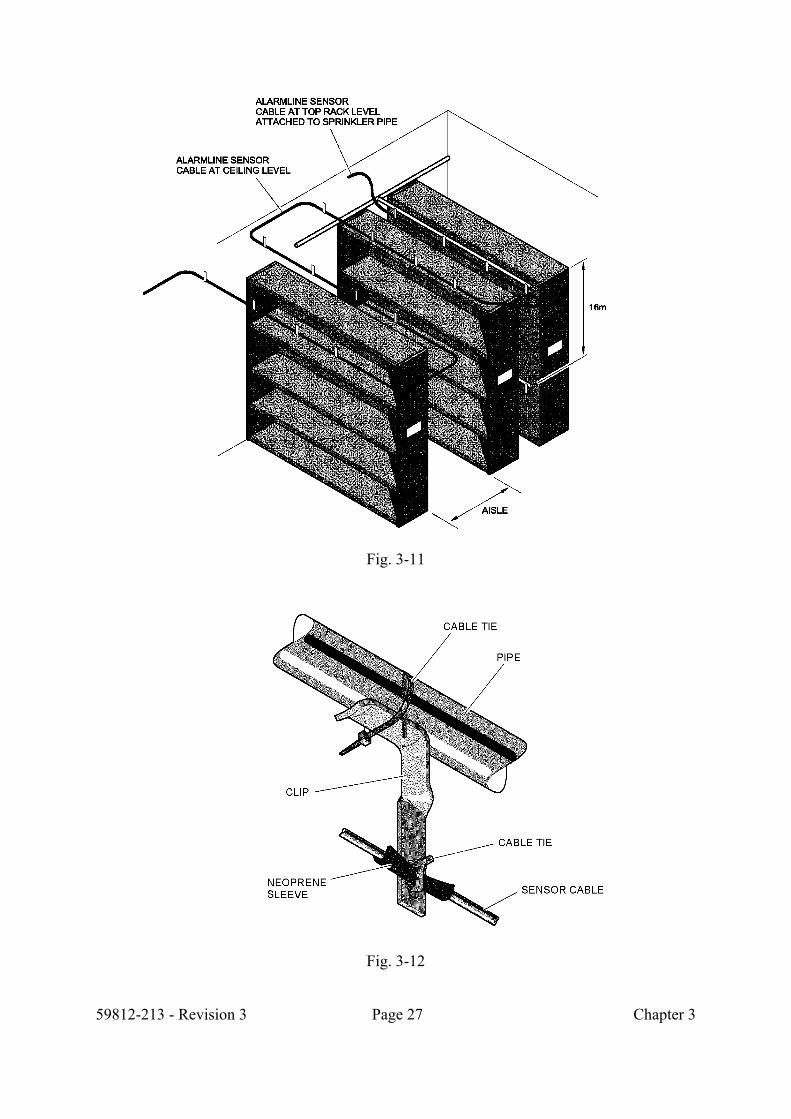
3.6 Rack Storage Alarmline Digital sensor cable can be used for general area coverage. The sensor cable works as a continuous heat detector, therefore the same minimum spacing requirements apply as for point type heat detectors. (Typically 7 metres spacing between cables.) Alarmline Digital sensor cable is used most effectively where environmental conditions or access difficulty prevent the use of conventional fire detection methods. The advantage of Alarmline Digital sensor cable is the flexibility to install at the point of risk, within the racks or the associated risk area. Alarmline Digital sensor cable can be installed to protect a high rack storage area by supporting the sensor cable from the ceiling, centred over the aisles, or fastened to the sprinkler system with cable ties or cable clamp stand-offs. Fig. 3-11 shows an example of rack protection. Fig 3-12 shows pipe clip (Part No. B6782-005). For a typical rack storage system, up to 4.5 metres high, sensor cable should be installed at ceiling level and within the area between back to back racks. For racks between 4.5 metres and 10 metres high, sensor cable should be installed at two levels. Racks of over 10 metres high should have sensor cable installed at three levels. In-rack level installations of sensor cable may use the rack construction for fixing using "universal" support brackets or edge clips. Careful positioning of the sensor cable is necessary to allow uninterrupted system operation and to prevent damage which may otherwise result from, for example, incorrectly loaded pallets. For racks containing high inflammables or other types of high risk products, response times may be further improved by protecting at each storage level using the rack steelwork for sensor cable support.
59812-213 - Revision 3 Page 27 Chapter 3
Fig. 3-11
Fig. 3-12

59812-213 - Revision 3 Page 28 Chapter 3
3.7 Freezer Warehouse Freezer warehouse installation is similar to that for rack storage, however certain precautionary measures need to be taken to ensure trouble-free installation and operation. Note: minimum operating temp. -65oC Installation should take place in temperatures no lower than -11oC. In freezers, the minimum bend radius should not be less than 100mm. The cable should be fixed at 1 metre intervals and on either side of all bends. Use a neoprene sleeve (Part No. B6782-008) between clips and sensor cable to ensure that the cable is not damaged by the clip. This also prevents the clip acting as a heatsink. All sensor jointing and terminations must be made within waterproof boxes suitable for the temperatures to be encountered. All electronic interfaces and display units must be installed outside the low temperature area. Fig. 3-13 shows the Alarmline Digital sensor cable routed within the racking providing protection close to the source of risk.
Fig. 3-13

59812-213 - Revision 3 Page 29 Chapter 3
3.8 Toxic Or Fuel Waste Drum Storage Figs 3-14 and 3-15 show two methods of installing Alarmline Digital sensor cable in a drum storage area. Fig. 3-14 shows the sensor cable installed directly over a row of 50 gallon drums. Sensor cable should be pulled taut every 15metres and held by strain relief fittings. Fig. 3-15 shows the sensor cable laced in serpentine fashion through a row of drums. Installation should be repeated at every level of drums, stacked or palletised, to maximise response time to overheat or fire where low flammability products are stored. To estimate the length of sensor cable needed, multiply 1.25 x length of drum rows to be protected in a serpentine fashion.
Fig. 3-14

59812-213 - Revision 3 Page 30 Chapter 3
Fig. 3-15

59812-213 - Revision 3 Page 31 Chapter 3
3.9 Power Distribution Equipment Alarmline Digital sensor cable installed within a control panel. Sensor cable should be laced between components in a horizontal pattern, fastened to the panel using approved fixings. Alarmline Digital sensor cable can be installed in parallel with the wiring harness of an electronic switchgear panel. The sensor cable should be laced to the harness with cable ties throughout the panel. Fig. 3-16 shows two examples of this type of installation.
Fig. 3-16
59812-213 - Revision 3 Page 32 Chapter 3
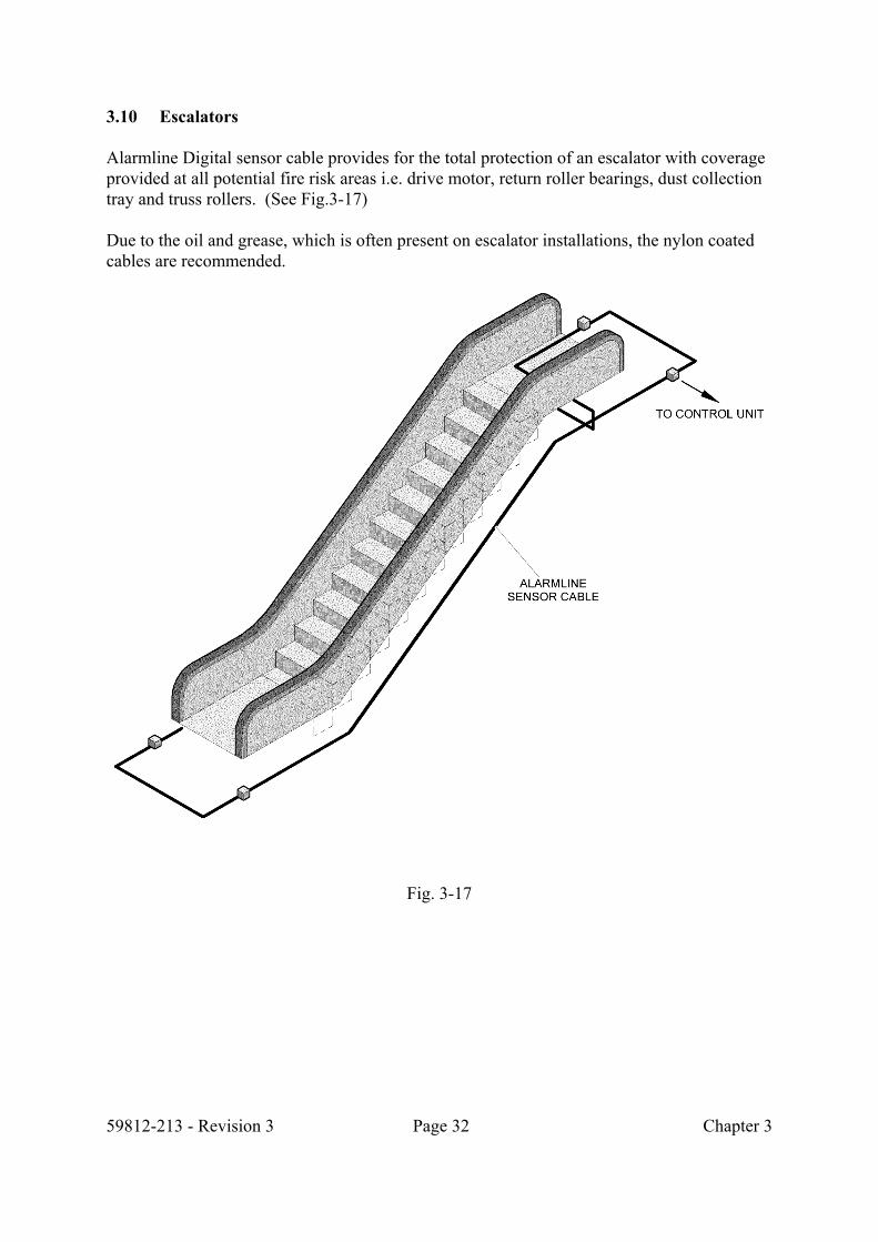
3.10 Escalators Alarmline Digital sensor cable provides for the total protection of an escalator with coverage provided at all potential fire risk areas i.e. drive motor, return roller bearings, dust collection tray and truss rollers. (See Fig.3-17) Due to the oil and grease, which is often present on escalator installations, the nylon coated cables are recommended.
Fig. 3-17

59812-213 - Revision 3 Page 33 Chapter 4
CHAPTER 4
SENSOR CABLE SELECTION 4.1 Standard Sensor Cable H8040 & H8045 These cables have a red/green identification (H8040) or red/black (H8045) Polyethylene braid outer covering and are suitable for internal environments, which range from clean and dry to where moderate amounts of dust and/or moisture are present. They should not be used in external environments, or where corrosive agents are present or where there is the risk of mechanical damage to the cable. Typical Installations are:- Cable trays Voids Electrical switchgear Service ducts Car parks Tunnels 4.2 Standard Sensor Cables H8040N & H8045N These are black nylon-covered versions of cables H8040 & H8045, which are suitable for external applications. 4.3 Sensor Cables H8028, H8069 & H9650 These cables are designed for use in external environments such as petrochemical plants, floating roof storage tanks and silos, and in hostile internal situations such as cold stores, engine bays and paint spray areas.

59812-213 - Revision 3 Page 34 Chapter 4
4.4.1 Cable Type H8028
This cable is black PVC covered and is suitable for external applications, excluding areas contaminated by chemical agents which could affect the PVC covering.
4.4.2 Cable Type H8069
This cable, which is red PVC covered, is suitable for external applications with the same limitations as H8028. It is not suitable for areas which are in direct sunlight.
4.4.3 Cable Type H9650
This Fluoropolymer covered cable is suitable for external applications where high ambient temperatures are expected or where protection against chemical agents may be required.
Please contact Kidde Fire Protection or an authorised distributor for assistance with cable selection if in any doubt.

59812-213 - Revision 3 Page 35 Chapter 5
CHAPTER 5
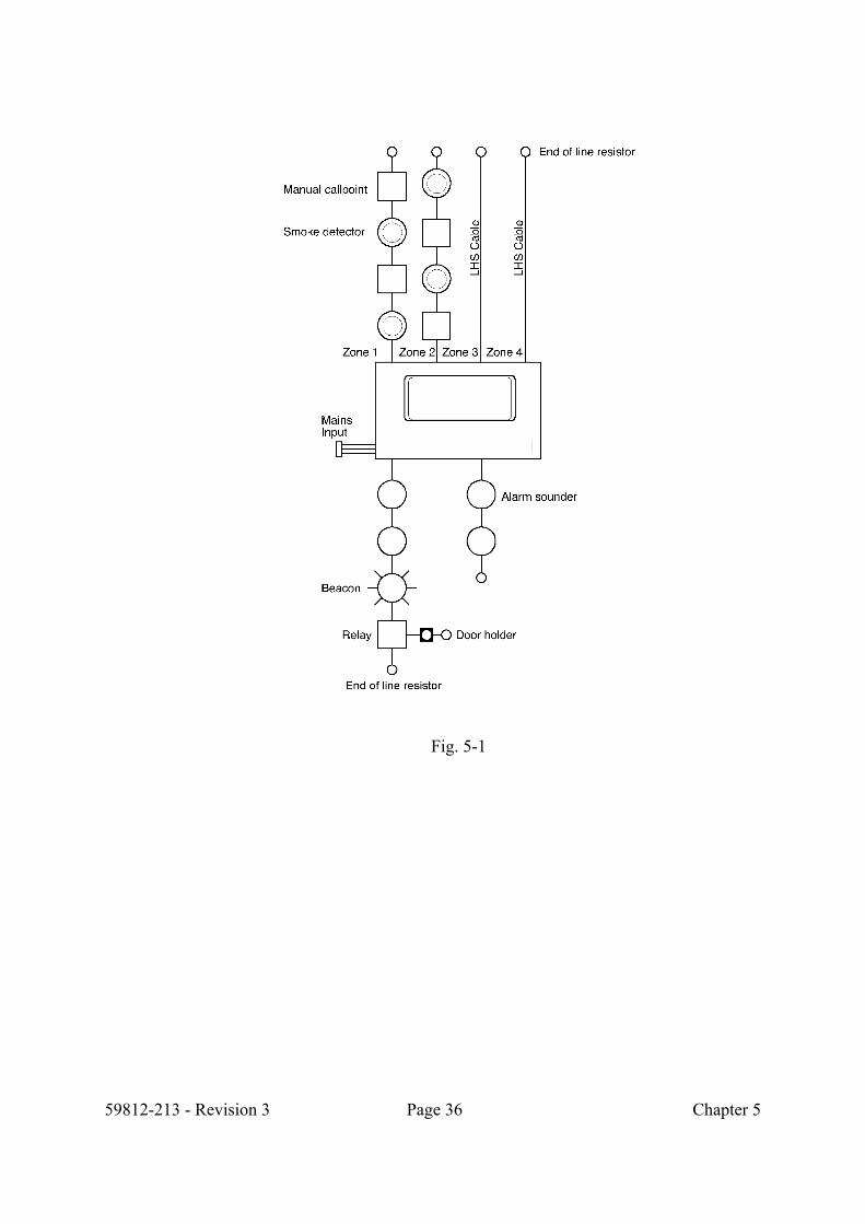
INSTALLATION 5.1 Installation Overview The installation of Alarmline Digital Sensor Cable is specific to the application. It is recommended that the installation is undertaken by trained and competent operators. The loop resistance of the cable must not exceed 100 ohm/km, typically at 20°C. It is important that the correct cable is selected for the environment together with the temperature at which an alarm should be given without risk of false alarms. It is important to avoid installation adjacent to material which can act as a heat sink. If necessary the cable should be suitably protected. Areas considered as potential hot spots may require a higher rated cable for that section, or suitable protection or avoidance measures taken. Alarmline Digital Sensor cable can be connected to most conventional fire alarm panels or interface units. (See Fig. 5-1), or analogue fire alarm panels via an analogue addressable Zone Monitor Unit (see Fig 5-2). The cable should be adequately supported to prevent sagging. It is not necessary to tension the cable, however on straight runs it is recommended that the cable is supported every 1 meter. Cable clip selection is site and application specific. The environmental conditions and practicality of clips to be used needs to be taken into consideration. Various fixings are described later in this section. Where possible, fixing of the cable should be planned to be the last item in the installation. The cable is supplied on drums of varying size in multiples of 200metres. Wherever possible, the zone should be installed in a continuous run. In the event that final fixing of the cable cannot take place, it should be supported temporary by “cable ties” to minimise the risk of damage. Overall care should be taken to prevent damage by crushing underfoot, mechanical impact, kinking or external heat sources.
5.2 Jointing
Alarmline Digital Sensor Cable has excellent stripping and jointing properties. The conductors can be soldered, crimped or jointed through a suitably rated junction box. The outer sheath has no electrical properties and does not need to be continuous through the joint(s). (See Fig. 5-3)
59812-213 - Revision 3 Page 36 Chapter 5
Fig. 5-1

59812-213 - Revision 3 Page 37 Chapter 5
Fig 5-2

59812-213 - Revision 3 Page 38 Chapter 5
5.3 Hazardous Areas Alarmline Digital Sensor Cable is approved for use within hazardous area installations. It is essential that the appropriate protective devices (Zener barriers or Galvanic Isolators) are used, compatible with the standard and the control equipment to which the cable is to be connected.
Fig. 5-3

59812-213 - Revision 3 Page 39 Chapter 5
5.4 Cable Fixings Fixing devices for the sensor cable are readily available for most applications. Owing to the nature of the sensor cable no special rules need to be followed, other than to ensure the fixing device does not damage the sensor cable. As with any electrical installation clamping should not be excessive. In ambient conditions above 0oC the sensor cable recommend minimum bend radius is 50mm. Should the bend be providing an anchor point in order to apply tension, the bend radius should be 50mm. The cable should be fixed at both sides of any bends. A short length of split neoprene sleeving provides protection at the fixing point and is recommended especially where sharp edges are likely to cut into the insulation, or where the sensor cable can chafe against surround metal or where the clip may act as a heatsink. The following examples are the most commonly used range of fixing clips. These will cover the majority of installations, Kidde Fire Protection or its distributors can advise on the best installation method for any particular installation. 5.4.1 Thermal spacer B6782-152 (150mm) – 151 (75mm) The thermal spacer was adapted as a sensor cable support by the UK electricity power generation companies and provides a sturdy, quickly installed mounting into unistrut. Fig. 5-4 shows the thermal spacer and how it is used.
Fig. 5-4
59812-213 - Revision 3 Page 40 Chapter 5
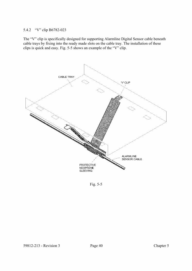
5.4.2 “V” clip B6782-023 The “V” clip is specifically designed for supporting Alarmline Digital Sensor cable beneath cable trays by fixing into the ready made slots on the cable tray. The installation of these clips is quick and easy. Fig. 5-5 shows an example of the “V” clip.
Fig. 5-5

59812-213 - Revision 3 Page 41 Chapter 5
5.4.3 Cable tray bracket B6782-002 To cover the top cable tray a tray bracket can be used. The bracket can be fitted to the cable tray or ceiling slab via a suitable nut and bolt arrangement. A neoprene sleeve is used to protect the cable and prevent the bracket acting as a heatsink as shown in Fig. 5-6 below.
Fig. 5-6
5.4.4 “T” clip B6782-004
The “T” clip is a general fixing clip, which is used for installing Alarmline Digital Sensor cable onto flat surfaces, i.e. walls or ceilings. This clip is generally used in area protection, or rack protection. The “T” clip is shown in Fig. 5-7 below. It is recommend that a tie-wrap is used to secure the cable where a change of direction occurs or where the cable may be subjected to vibration or snagging.
Fig. 5-7

59812-213 - Revision 3 Page 42 Chapter 5
5.4.5 Edge clip B6782-003 The edge clip is suitable for fixing to structural beams of buildings, as shown in Fig. 5-8 below.
Fig. 5-8
5.4.6 Knock-on clip B6782-003 (2-3mm), B6782-024 (3-8mm), B6782-025 (8-14mm) and B6782-0026 (14-20mm) The Knock-on clip can be used to fix to girders and metal edges, they are available in different sizes to accommodate different thickness of girder as shown below in Fig. 5-9.
Fig. 5-9

59812-213 - Revision 3 Page 43 Chapter 6
CHAPTER 6
COMMISSIONING & TEST PROCEDURE 6.1 Passive Checks
a) Visually inspect the cable to ensure correct installation in accordance with the
specification and system design. b) Ensure that the correct cable type has been installed.
c) Check each cable for mechanical damage, that all clips are in place and that
the cable is correctly installed within the clips.
d) Inspect all joints and terminations to ensure that they are correctly installed and appropriate for the application and environment.
e) Ensure that the correct value of end of line resistor is fitted appropriate to the
equipment to which it is connected.
f) Check that insulation resistance between conductors (excluding end of line resistors) is 1000m ohm per km minimum
g) Check that conductor resistance is 100 ohm per km maximum

59812-213 - Revision 3 Page 44 Chapter 6
6.2 Test Procedure
Operation of Alarmline Digital Sensor cable is a “one shot” operation, therefore it is recommended that the following test procedure is adopted: a) Add a 1m length of cable to the end of the zone, with the appropriate end of
line resistors fitted.
b) This cable should then be installed within a suitable 1 Metre Test Oven available from Kidde Fire Protection (Part No. B6784-006) and the temperature set to the highest alarm operating level for the cable.
c) The oven should then be brought up to temperature and the result recorded.
d) Operation of the fire control panel and any relevant interface units should be
recorded for correct operation.
e) Remove the test cable, install the end of line resistor and reset the system.
f) For a passive check, place a short circuit across the end of line resister. Record the result.
g) Disconnect one end of the line resistor to cause an open circuit fault. Record
the result.
h) Reinstate the system to operational standard.