all purpose vinyl garden sheds vinyl garden...
TRANSCRIPT
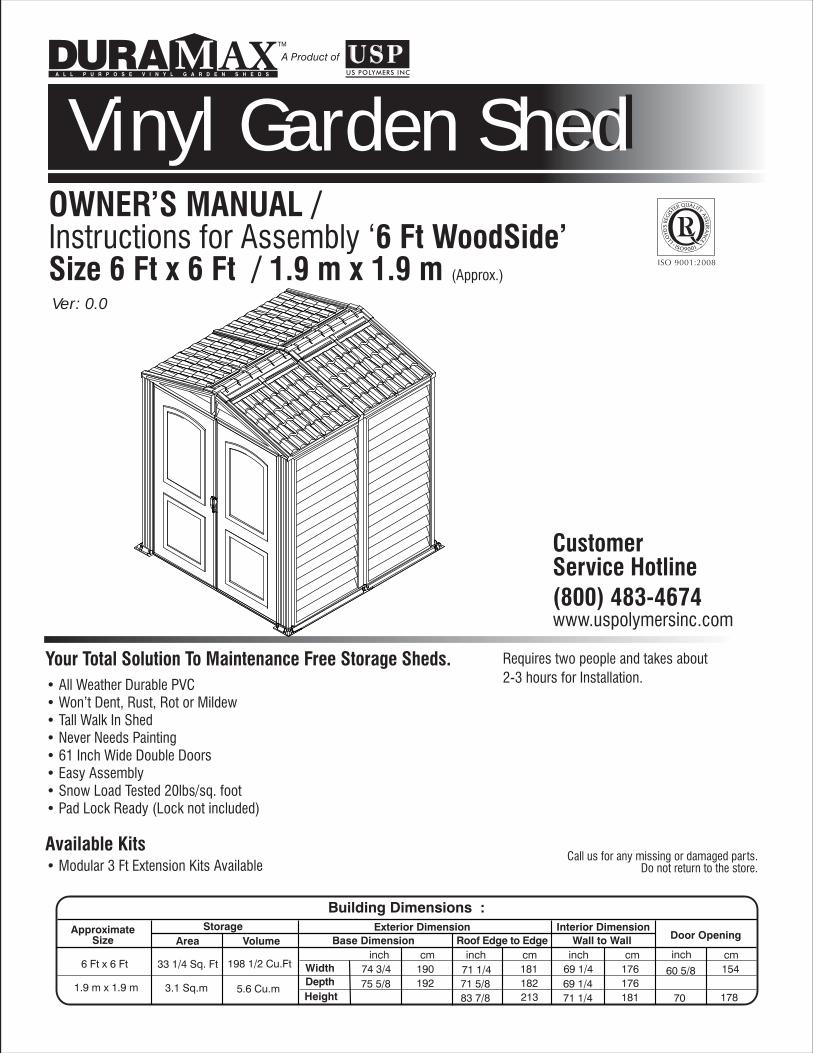
• All Weather Durable PVC• Won’t Dent, Rust, Rot or Mildew• Tall Walk In Shed• Never Needs Painting• 61 Inch Wide Double Doors• Easy Assembly• Snow Load Tested 20lbs/sq. foot• Pad Lock Ready (Lock not included)
Call us for any missing or damaged parts.Do not return to the store.
CustomerService Hotline(800) 483-4674www.uspolymersinc.com
Requires two people and takes about2-3 hours for Installation.
Your Total Solution To Maintenance Free Storage Sheds.
Available Kits• Modular 3 Ft Extension Kits Available
Ver: 0.0
Vinyl Garden ShedVinyl Garden ShedA Product of
TM
A L L P U R P O S E V I N Y L G A R D E N S H E D S
OWNER’S MANUAL / Instructions for Assembly ‘6 Ft WoodSide’Size 6 Ft x 6 Ft / 1.9 m x 1.9 m (Approx.)
Building Dimensions :Approximate
SizeStorage Exterior Dimension Interior Dimension
6 Ft x 6 Ft 33 1/4 Sq. Ft 198 1/2 Cu.Ft
Roof Edge to EdgeBase Dimension Door Opening
1.9 m x 1.9 m 3.1 Sq.m 5.6 Cu.m
WidthDepthHeight
inch cm74 3/4 190
inch cm
75 5/8 19271 1/4 18171 5/8 18283 7/8 213
inch cm69 1/4 176
inch cm
69 1/4 17660 5/8 154
70 17871 1/4 181
Wall to WallArea Volume

1
Duramax Garden ShedLimited Fifteen Year Warranty
U.S. Polymer Inc. will send a replacement part free of charge, in the event of material defects and or workmanship for a period of fifteen years from the date of purchase.
This warranty is extended only to the original purchaser. A purchase receipt or other proof of date of original purchase will be required before warranty service is rendered. In no event shall we pay the cost of flooring, labor, installation or any other costs related thereto.
This warranty only covers failures due to defects in material or workmanship which occurs during normal use and does not extend to color change arising due to normal weathering or to damage resulting from misuse or neglect, commercial use, failure to follow assembly instructions and the owner’s manual (including proper anchoring of the shed), painting, forces of nature and other causes which is beyond our control.
Claims under this warranty must be made within the warranty period by calling 1-800-483-4674 or mail in a dated sales slip and clear photograph of the part to:
U.S. Polymers, Inc.1057 S. Vail Ave, Montebello, CA 90640.
We reserve the right to discontinue or change components. If a component has been discontinued or is not available,U.S. Polymers, Inc. reserves the right to substitute a component of equal quality as may be compatible.
Limits and Exclusions
There are no express warranties except as listed above. The warrantor shall not be liable for incidental or consequential damages resulting from the use of this product, or arising out of any breach of this warranty. All express warranties are limited to the warranty period set forth above . Some states do not allow the exclusion or limitation on how long an implied warranty lasts, so the above limitations may not apply to you.
This warranty gives you specific legal rights and you may also have other rights which vary from state to state or country to country.
“We recommend to clear snow from the Roof top after each Snowfall.”

2
SAFETY & PRECAUTIONS
Before You Begin...
1. Check your local building codes regarding footings, location, etc.
2. Select a site that allows enough working space around the shed.
3. Determine building foundation and anchor system.
4. Read and understand the Owner’s manual enclosed in the package.
5. Follow all directions and dimensions thoroughly.
6. Follow the steps given in the manual carefully for correct assembly.
7. Make sure all parts are present before you start assembling.
8. BE SAFE : Follow safety instructions and avoid injury. (See inside page).
9. GROUND MUST BE EVEN : Make sure the foundation frame lies flat on the ground. If the earth bed is uneven, remove sod and other debris andlevel it with a flat shoval.
10. Separate contents of the carton by the part number and review the list. Be sure you have all the necessary parts for your shed.Refer Owner’s manual for part list.
CAUTIONSharp Edges
3
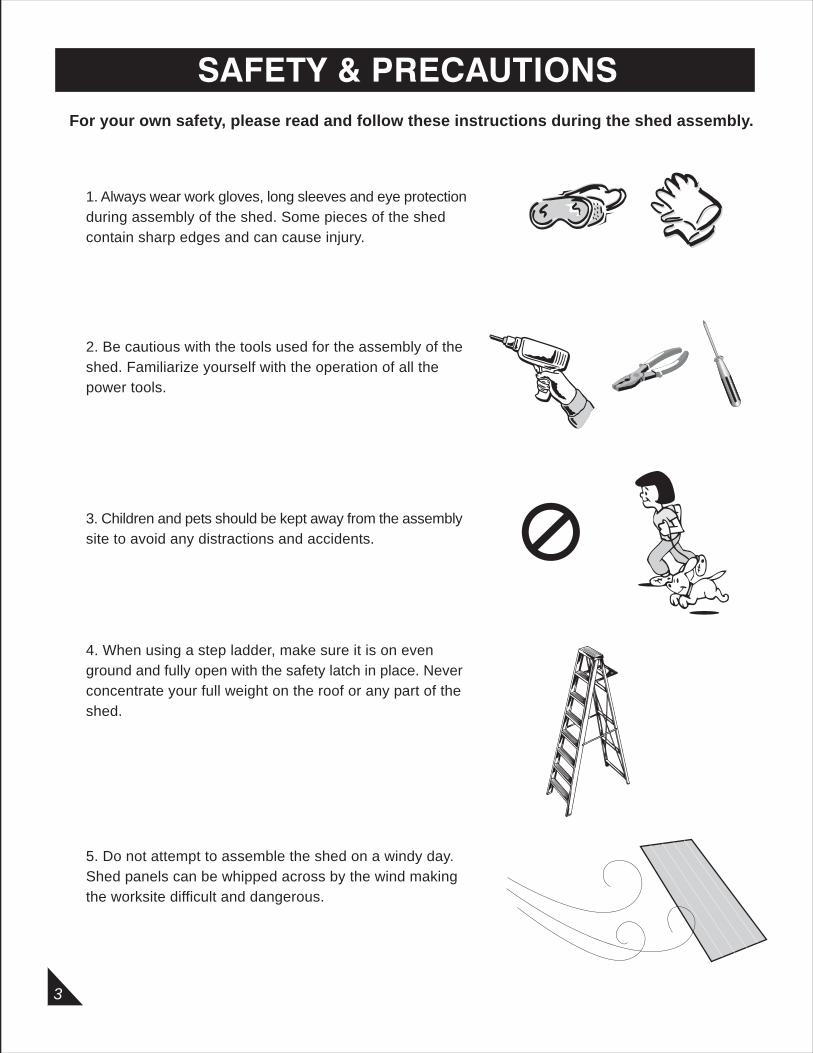
SAFETY & PRECAUTIONSFor your own safety, please read and follow these instructions during the shed assembly.
1. Always wear work gloves, long sleeves and eye protection during assembly of the shed. Some pieces of the shed contain sharp edges and can cause injury.
2. Be cautious with the tools used for the assembly of the shed. Familiarize yourself with the operation of all the power tools.
3. Children and pets should be kept away from the assembly site to avoid any distractions and accidents.
4. When using a step ladder, make sure it is on even ground and fully open with the safety latch in place. Never concentrate your full weight on the roof or any part of the shed.
5. Do not attempt to assemble the shed on a windy day. Shed panels can be whipped across by the wind making the worksite difficult and dangerous.
4
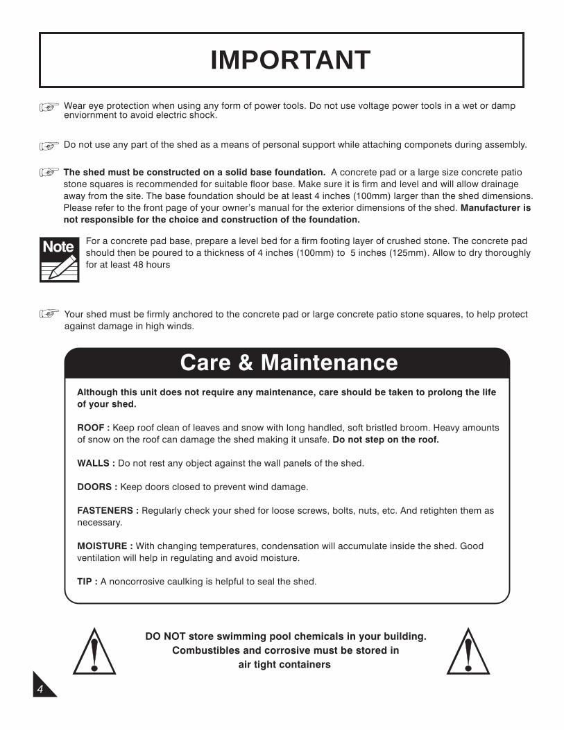
IMPORTANTWear eye protection when using any form of power tools. Do not use voltage power tools in a wet or dampenviornment to avoid electric shock.
Do not use any part of the shed as a means of personal support while attaching componets during assembly.
The shed must be constructed on a solid base foundation. A concrete pad or a large size concrete patiostone squares is recommended for suitable floor base. Make sure it is firm and level and will allow drainageaway from the site. The base foundation should be at least 4 inches (100mm) larger than the shed dimensions.Please refer to the front page of your owner’s manual for the exterior dimensions of the shed. Manufacturer is not responsible for the choice and construction of the foundation.
For a concrete pad base, prepare a level bed for a firm footing layer of crushed stone. The concrete padshould then be poured to a thickness of 4 inches (100mm) to 5 inches (125mm). Allow to dry thoroughly for at least 48 hours
Your shed must be firmly anchored to the concrete pad or large concrete patio stone squares, to help protectagainst damage in high winds.
Care & MaintenanceAlthough this unit does not require any maintenance, care should be taken to prolong the life of your shed.
ROOF : Keep roof clean of leaves and snow with long handled, soft bristled broom. Heavy amountsof snow on the roof can damage the shed making it unsafe. Do not step on the roof.
WALLS : Do not rest any object against the wall panels of the shed.
DOORS : Keep doors closed to prevent wind damage.
FASTENERS : Regularly check your shed for loose screws, bolts, nuts, etc. And retighten them as necessary.
MOISTURE : With changing temperatures, condensation will accumulate inside the shed. Good ventilation will help in regulating and avoid moisture.
TIP : A noncorrosive caulking is helpful to seal the shed.
DO NOT store swimming pool chemicals in your building. Combustibles and corrosive must be stored in air tight containers
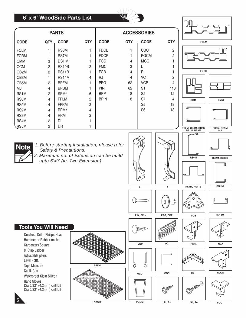
Cordless Drill - Philips HeadHammer or Rubber malletCarpenters Square8’ Step LadderAdjustable pliersLevel - 3ft.Tape MeasureCaulk GunWaterproof Clear SiliconHand GlovesDia 5/32” (4.2mm) drill bitDia 5/32” (4.2mm) drill bit
Tools You Will Need
2. Maximum no. of Extension can be build upto 6’x9’ (ie. Two Extension).
Note 1. Before starting installation, please refer Safety & Precautions.
5
CB2M, CB3M, CB5M RS1M, RS3M
RS5M RS2M, RS10B
DSHM
RS14M
CCM CMM
FDCL
FDCR
FCB
FMC
FCC
RJCBC
PIN, BPIN PPG, BPP
S1, S2
CODE QTY
FCLM 1FCRM 1CMM 3CCM 2 CB2M 2CB3M 1CB5M 2 MJ 4RS1M 2RS8M 4RS9M 4RS2M 4RS3M 4RS4M 2RS5M 2
CODE QTY
FDCL 1FDCR 1FCC 4FMC 3 FCB 4RJ 4 PPG 62PIN 62BPP 8BPIN 8
CODE QTY
RS6M 1RS7M 1DSHM 1RS10B 2RS11B 1RS14M 4 BPFM 1BPBM 1SPM 6FPLM 2FPRM 2RPM 4RRM 2DL 1DR 1
PARTS ACCESSORIES
FCLM
FCRM
RS8M, RS9MMJ
S5, S6
L R
6’ x 6’ WoodSide Parts List
CODE QTY
CBC 2PGCM 2MCC 1L 1R 1VC 2VCP 4S1 113S2 12S7 4S5 18S6 18
VCVCP
MCC
RS4M, RS11B
BPBM
BPFM
PGCM
R

6’ x 6’ WoodSide Exploded View
6
DL
DR
FCLM
FCRM
BPFM
CB2M
CB2M
CCM
CMM
CB3M
FPLM
FPRM
SPM
SPM
CB5M
CMM
RPM
RRM
MJ
CB5M
MJ
CMM
RS3M
MJ
RS3M
RS4M
RS4M
RS6M
RS7M
RPM
BPBM
RS11B
SPM
CCM
SPM
SPM
SPM
DSHM
RS1M
RS9M
RS8M
RS9M RS3M
RS3M
RS2M
RS2M
RS2M
RS2M
RS9MRS10B
RS10BRS9M
RS8M
FPRM
FPLM
RS1M
RS5M
RS5M
MJ
RPM
RPM
RRM
7
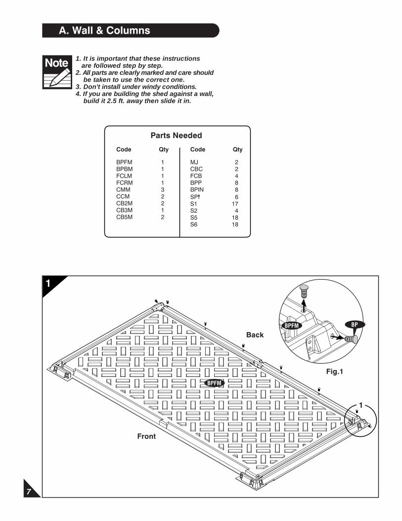
Note 1. It is important that these instructions are followed step by step. 2. All parts are clearly marked and care should be taken to use the correct one.3. Don’t install under windy conditions.4. If you are building the shed against a wall, build it 2.5 ft. away then slide it in.
A. Wall & Columns
1
1
Fig.1
Back
Front
BP
BPFM
BPFM
Parts Needed
Code Qty
BPFM 1BPBM 1FCLM 1FCRM 1CMM 3CCM 2CB2M 2CB3M 1CB5M 2
Code Qty
MJ 2CBC 2FCB 4BPP 8BPIN 8SP 6S1 17S2 4S5 18S6 18
8
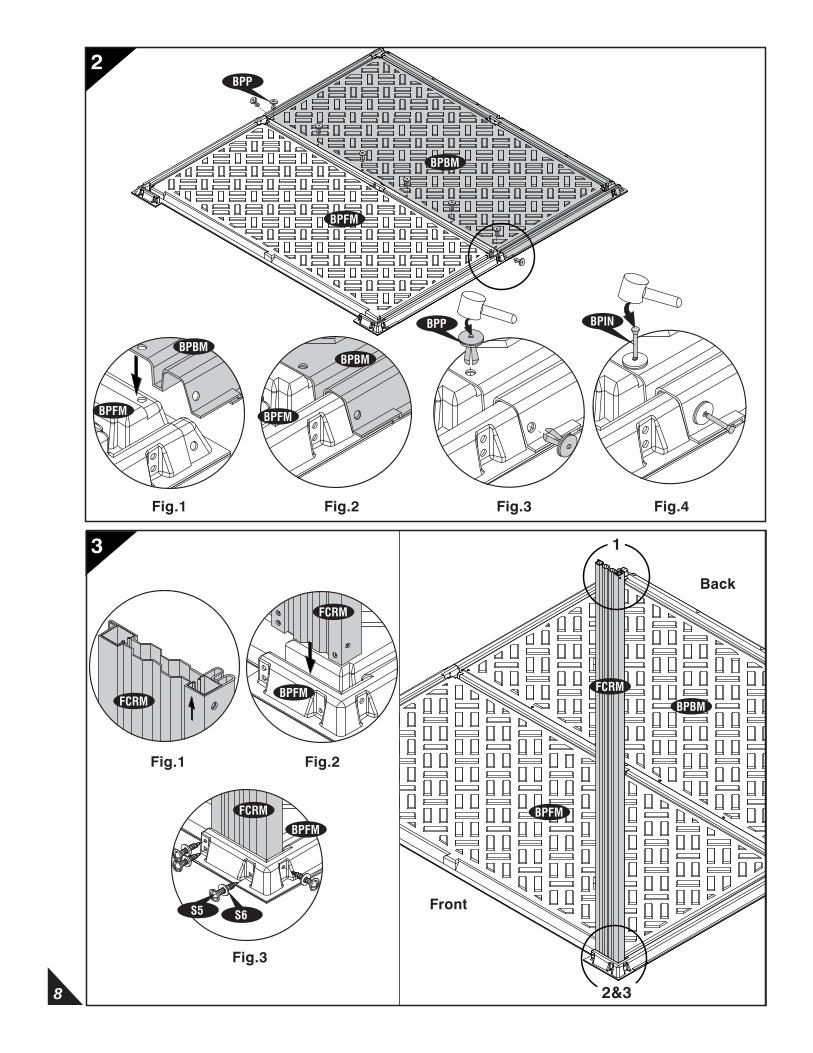
2
3
Front
Back
Fig.1 Fig.2 Fig.3 Fig.4
Fig.3
1,2,3&4
BPBM
BPFM
BPBM
BPFM
BPP BPIN
1
BPFM
BPBM
FCRM
Fig.1
FCRM
Fig.2
FCRM
BPFM
S5 S6
BPFM
FCRM
BPP
BPFM
BPBM
2&3
9
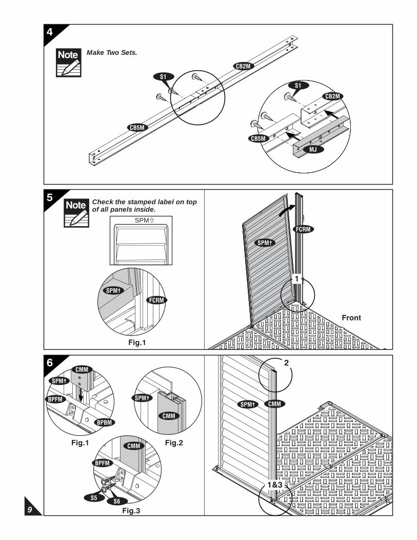
Check the stamped label on top of all panels inside.Note
SPM
4
6
5
Make Two Sets.Note
SPM
Front
Fig.1
Fig.1
1&3
Fig.2
Fig.3
CB5M
CB2M
S1
MJ
S1
CB5M
CB2M
1
SPM
FCRM
SPM
FCRM
CMMSPM
CMM
2
S5
CMM
BPFM
S6
SPMBPFM
CMM
BPBM
SPM
10
Fig.1
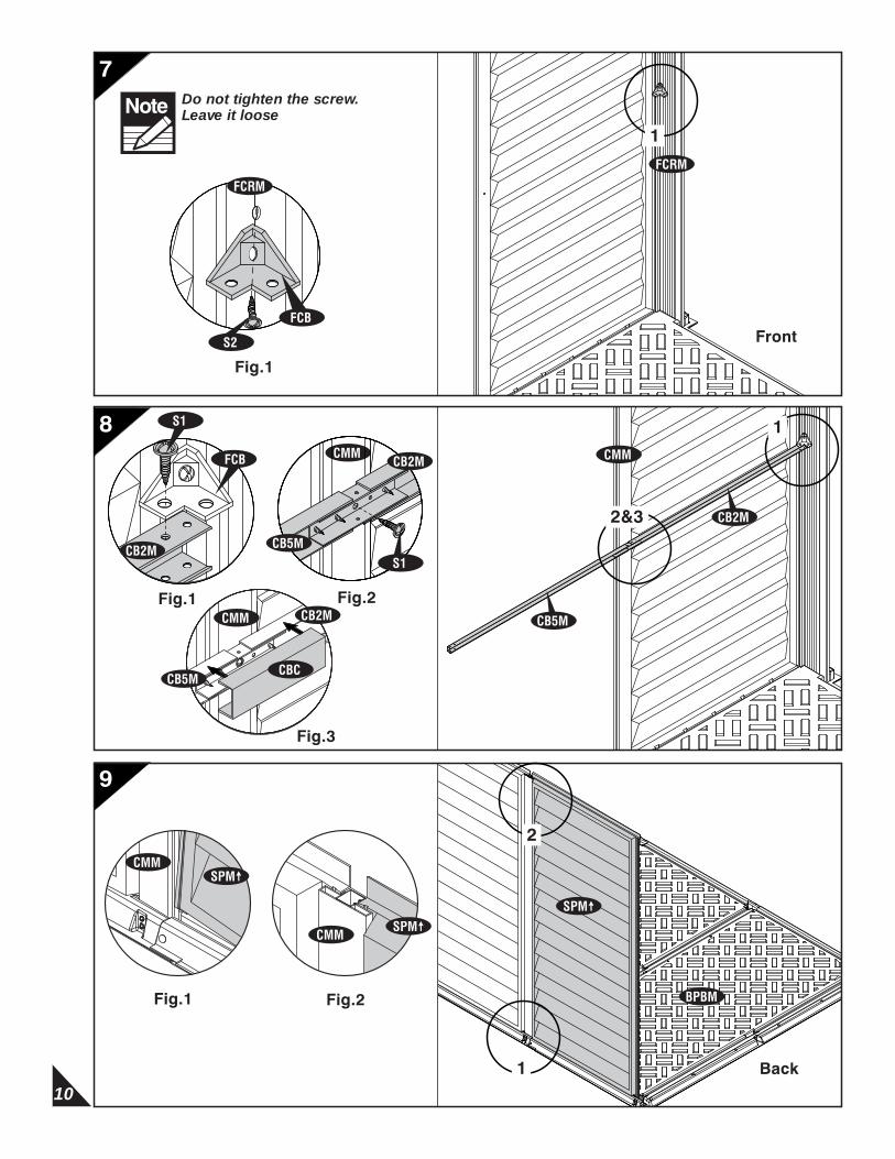
Do not tighten the screw. Leave it looseNote
Fig.3
7
9
8
Front
Fig.1 Fig.2
CMMCB2M
S1
CB5M
CBCCB5M
CB2MCMM
2&3 CB2M
CB5M
CMM
Back
Fig.1 Fig.2
FCRM
1
FCB
S2
FCRM
1
CB2M
FCB
S1
SPM
BPBM
1
2
SPMCMM
CMMSPM
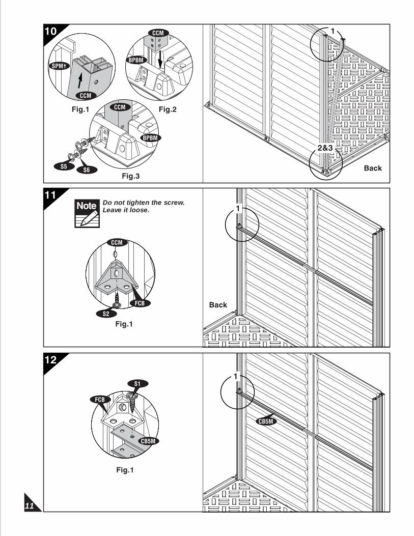
Fig.1
11
10
Fig.2
2&3
Fig.3Back
Back
Fig.1
Do not tighten the screw. Leave it loose.Note
CCM
FCB
Fig.1
CB5M
S1
FCB
S5
S2
CB5M
11
12
CCM
SPM
CCM
BPBM
CCM
BPBM
S6
1
1
1

12
SPM
CMM
CB3M
Back
Back
1&3
2
Fig.1 Fig.2
Fig.3
CMM
SPM
CB3M
FCBS1
CB3M CB5M
S1
CB3M
S1
CMM
3
Fig.1 Fig.2
Fig.3
13
14
15
Fig.2Fig.1
CCM
CMM
SPM
BPBM
CMM
SPM
S5 S6
CMM
BPBM
1&2
1
2
CCM SPM
CCM
SPM

13
Back Wall
CCM
Fig.3
FCB
CCM
S2
Do not tighten the screw. Leave it loose.Note
CCM
1
1
16
17
18
SPM
S5
Fig.1 Fig.2
S6
SPM
2&3
1
Fig.1
Fig.1
1
CCM
CCM
BPBM
CCM
BPBM
SPM
SPMCMM
14
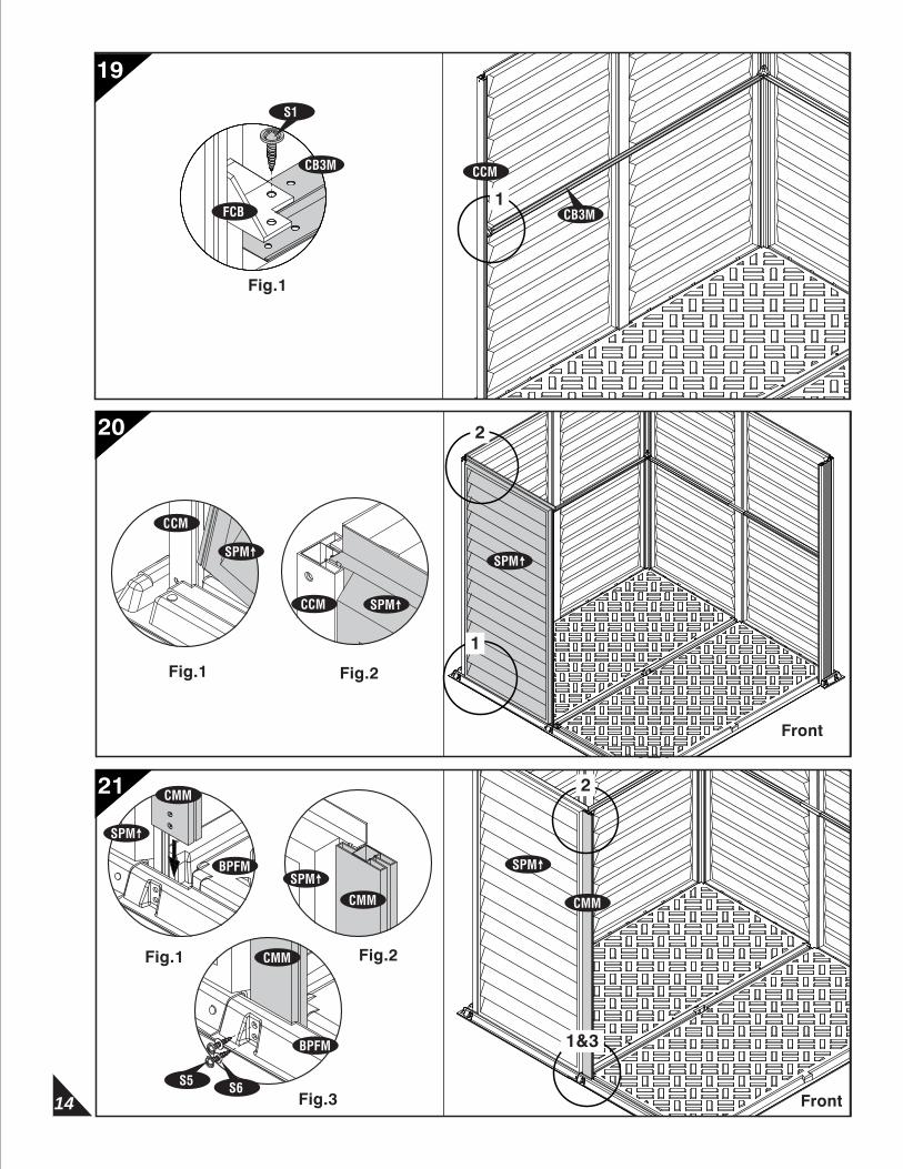
CB3M
S1
FCB
2
19
20
21
CCM
1
Fig.1
Front
SPM
Fig.1 Fig.2
Fig.3 Front
1&3
S5
CB3M
CMMCMM
S6
1
2
SPM
CMM
BPFM
CMM
CMM
BPFM
SPM
SPM
Fig.2Fig.1
CCM SPM
CCM
SPM
15
2
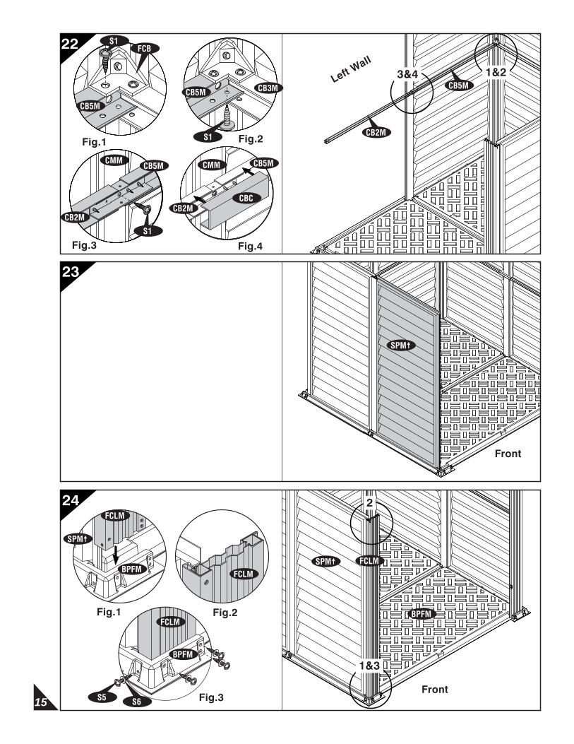
22
23
24
Left Wall
3&4
Fig.1
CB5M
FCBS1
CB5M CB3M
S1 Fig.2
Fig.3 Fig.4
CMM
CBC
CB5MCMM
CB2M
1&2
Front
1&3
S5 S6
Fig.1 Fig.2
Fig.3Front
CB5M
CB2M
CB5M
S1
CB2M
SPM
SPM FCLM
BPFM
SPM
FCLM
BPFM FCLM
FCLM
BPFM
16
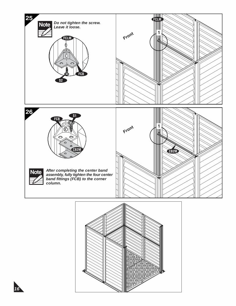
Front 1
25
26
Do not tighten the screw. Leave it loose.Note
Front 1
FCLM
After completing the center band assembly, fully tighten the four center band fittings (FCB) to the corner column.
Note
FCB
S2
FCLM
CB2M
FCBS1
CB2M
17
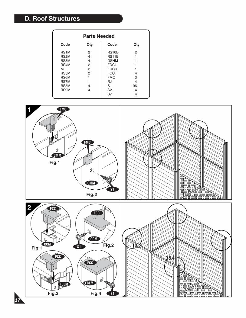
D. Roof Structures
Parts Needed
Code Qty
RS1M 2RS2M 4RS3M 4RS4M 2MJ 2RS5M 2RS6M 1RS7M 1RS8M 4RS9M 4
Code Qty
RS10B 2RS11B 1DSHM 1FDCL 1FDCR 1FCC 4FMC 3RJ 4S1 96S2 4S7 4
Fig.1
Fig.2
1
CMM
FMC
S1
CMM
FMC
1&2
3&4
Fig.2
Fig.3 Fig.4
2
Fig.1CCM
FCC
S1
CCM
FCC
FCC
FCLM
S1
FCC
FCLM

18
6’ x 6’ WoodSide Roof Structure Exploded View
Front
Fig.1 Fig.2
Fig.3 Fig.4
3
3&4
1&2
S1
FDCR
FCRM
FCRM
FDCR
S1
FDCL
FDCL
FCLMFCLM
FCRM
FCLM
RS2M
RS2M
DSHM
RS8MRS9M
RS10B
RS8M RS9M
RS1M
RS2M
RS2M
RS10B
RS1M
RS9M
RS9M
RS8M
RS8MRS3M
RS3M
RS6M
RS7M
RS4M
RS4M
MJ
MJ
RS11B
RS3M
RS3M
RS5M
RS5M