alternative support structures for...
TRANSCRIPT

1
ALTERNATIVE SUPPORT STRUCTURES FOR CANTILEVER SIGNAL/SIGN STRUCTURES
By
KATHRYN L. JENNER
A THESIS PRESENTED TO THE GRADUATE SCHOOL OF THE UNIVERSITY OF FLORIDA IN PARTIAL FULFILLMENT
OF THE REQUIREMENTS FOR THE DEGREE OF MASTER OF ENGINEERING
UNIVERSITY OF FLORIDA
2010

2
© 2010 Kathryn L. Jenner

3
To my parents, Joann and Stu Without your support, I would not have been able to accomplish this.

4
ACKNOWLEDGMENTS
I would like to acknowledge and thank the Florida Department of Transportation for
providing the funding for this research project. This project was a collaborative effort between
the University of Florida and the FDOT Structures Research Laboratory in Tallahassee. I would
also like to acknowledge and thank Dr. Ronald A. Cook for continually providing advice and
knowledge to help make this project successful.

5
TABLE OF CONTENTS
ACKNOWLEDGMENTS ...............................................................................................................4
page
LIST OF TABLES ...........................................................................................................................8
LIST OF FIGURES .........................................................................................................................9
ABSTRACT ...................................................................................................................................13
CHAPTER
1 INTRODUCTION ..................................................................................................................15
2 BACKGROUND ....................................................................................................................17
2.1 Current Anchor Bolt Foundation System ......................................................................17 2.2 Alternative Foundation Systems ...................................................................................20
2.2.1 Steel Pipes with Plates Welded at Four Locations ............................................20 2.2.2 Geometric Hollow Section ................................................................................21 2.2.3 Pipe with Welded Studs ....................................................................................22 2.2.4 Helical Pipes .....................................................................................................22 2.2.5 Embedded Geometric Tapered Section .............................................................23
2.3 Alternative Foundations from Other Industries ............................................................23 2.3.1 Transmission Line Foundations ........................................................................24 2.3.2 Wind Turbine Foundations ...............................................................................26 2.3.3 Cellular Tower Foundations ..............................................................................27 2.3.4 Advertising Monopole Foundations ..................................................................28
2.4 Selection ........................................................................................................................28
3 DESIGN IMPLICATIONS ....................................................................................................38
3.1 Design for Torsion ........................................................................................................38 3.1.1 Equivalent Concrete Breakout Strength in Shear ..............................................38 3.1.2 Equivalent Side-Face Blowout Strength ...........................................................43
3.2 Design for Flexure ........................................................................................................44 3.2.1 Equivalent Concrete Breakout Strength in Shear ..............................................45 3.2.2 Equivalent Side-Face Blowout Strength ...........................................................46
3.3 Design Implications Summary ......................................................................................48
4 DEVELOPMENT OF EXPERIMENTAL PROGRAM ........................................................56
4.1 Description of Test Apparatus ......................................................................................57 4.2 Embedded Pipe and Plate Design .................................................................................59
4.2.1 Concrete Breakout and Bearing Strength ..........................................................59 4.2.2 Welded Stiffener Plates Design ........................................................................60
6
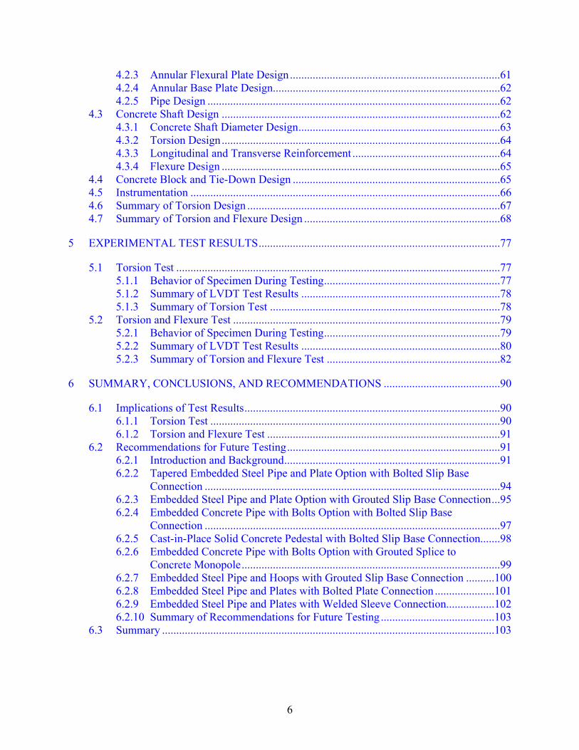
4.2.3 Annular Flexural Plate Design ..........................................................................61 4.2.4 Annular Base Plate Design................................................................................62 4.2.5 Pipe Design .......................................................................................................62
4.3 Concrete Shaft Design ..................................................................................................62 4.3.1 Concrete Shaft Diameter Design .......................................................................63 4.3.2 Torsion Design ..................................................................................................64 4.3.3 Longitudinal and Transverse Reinforcement ....................................................64 4.3.4 Flexure Design ..................................................................................................65
4.4 Concrete Block and Tie-Down Design .........................................................................65 4.5 Instrumentation .............................................................................................................66 4.6 Summary of Torsion Design .........................................................................................67 4.7 Summary of Torsion and Flexure Design .....................................................................68
5 EXPERIMENTAL TEST RESULTS .....................................................................................77
5.1 Torsion Test ..................................................................................................................77 5.1.1 Behavior of Specimen During Testing ..............................................................77 5.1.2 Summary of LVDT Test Results ......................................................................78 5.1.3 Summary of Torsion Test .................................................................................78
5.2 Torsion and Flexure Test ..............................................................................................79 5.2.1 Behavior of Specimen During Testing ..............................................................79 5.2.2 Summary of LVDT Test Results ......................................................................80 5.2.3 Summary of Torsion and Flexure Test .............................................................82
6 SUMMARY, CONCLUSIONS, AND RECOMMENDATIONS .........................................90
6.1 Implications of Test Results ..........................................................................................90 6.1.1 Torsion Test ......................................................................................................90 6.1.2 Torsion and Flexure Test ..................................................................................91
6.2 Recommendations for Future Testing ...........................................................................91 6.2.1 Introduction and Background ............................................................................91 6.2.2 Tapered Embedded Steel Pipe and Plate Option with Bolted Slip Base
Connection ........................................................................................................94 6.2.3 Embedded Steel Pipe and Plate Option with Grouted Slip Base Connection ...95 6.2.4 Embedded Concrete Pipe with Bolts Option with Bolted Slip Base
Connection ........................................................................................................97 6.2.5 Cast-in-Place Solid Concrete Pedestal with Bolted Slip Base Connection.......98 6.2.6 Embedded Concrete Pipe with Bolts Option with Grouted Splice to
Concrete Monopole ...........................................................................................99 6.2.7 Embedded Steel Pipe and Hoops with Grouted Slip Base Connection ..........100 6.2.8 Embedded Steel Pipe and Plates with Bolted Plate Connection .....................101 6.2.9 Embedded Steel Pipe and Plates with Welded Sleeve Connection .................102 6.2.10 Summary of Recommendations for Future Testing ........................................103
6.3 Summary .....................................................................................................................103

7
APPENDIX
A TEST APPARATUS DRAWINGS ......................................................................................110
B DESIGN CALCULATIONS ................................................................................................121
Torsion Design Calculations .................................................................................................121 Torsion and Flexure Design Calculations .............................................................................152
C TEST DATA .........................................................................................................................186
Torsion Test Data .................................................................................................................186 Torsion and Flexure Test Data .............................................................................................188
D DESIGN GUIDELINES .......................................................................................................191
Base Connection Design .......................................................................................................191 Embedded Pipe Design .........................................................................................................192 Embedded Pipe and Torsion Plates Design ..........................................................................192 Embedded Pipe and Flexure Plate Design ............................................................................194 Concrete Pedestal Reinforcement .........................................................................................196 Sample Design Guidelines ....................................................................................................200
LIST OF REFERENCES .............................................................................................................213
BIOGRAPHICAL SKETCH .......................................................................................................215
8
LIST OF TABLES
Table
page
2-1 Support structure foundation frequency of use ..................................................................30
4-1 Summary of pertinent design strengths for torsion test with 5500 psi concrete ................76
4-2 Summary of pertinent design strengths for torsion and flexure test with 5500 psi concrete ..............................................................................................................................76
9
LIST OF FIGURES
Figure
page
1-1 Failed cantilever sign structure ..........................................................................................16
1-2 Failed foundation during post-failure excavation ..............................................................16
2-1 How torsional and flexural moments are transferred using anchor bolts ..........................30
2-2 Alternative foundation: steel pipe with four welded plates ...............................................31
2-3 Leveling nut detail .............................................................................................................31
2-4 Alternate foundation: geometric hollow section ................................................................32
2-5 Alternate foundation: pipe with welded studs ...................................................................32
2-6 Alternate foundation: helical pipes ....................................................................................33
2-7 Alternate foundation: geometric tapered section ...............................................................33
2-8 Cast-in-place foundation for transmission lines ................................................................34
2-9 Potential forces acting on a transmission line foundation .................................................34
2-10 Drilled concrete piles for transmission lines ......................................................................35
2-11 Typical transmission line structures compared to a cantilever sign structure ...................35
2-12 Prestressed soil anchor .......................................................................................................36
2-13 Grouted soil anchors ..........................................................................................................36
2-14 Mat foundation for wind turbines ......................................................................................37
2-15 Pad and pier foundations for wind turbines .......................................................................37
3-1 Concrete breakout of an anchor caused by shear directed parallel to the edge for a cylindrical foundation ........................................................................................................49
3-2 Differences between concrete breakout failures for anchor bolts in shear and embedded pipe and plate section in torsion .......................................................................49
3-3 Concrete breakout formula for an anchor loaded in shear .................................................49
3-4 Shear breakout of a single anchor in rectangular concrete ................................................50
3-5 Shear breakout for a single anchor in cylindrical concrete ................................................50

10
3-6 Determination of AVcp based on ≈35° failure cone for embedded pipe and plate section ................................................................................................................................51
3-7 Similarities of failure cones in side-face blowout of a headed anchor in tension and the embedded pipe and plate section in torsion .................................................................52
3-8 Concrete side-face blowout equation for a headed anchor in tension ...............................52
3-9 Schematic of anticipated failure and bearing area of torsion plate ....................................53
3-10 Flexure resolved into a tension and compression on an anchor bolt system and the proposed system .................................................................................................................53
3-11 The tensile and compressive forces seen as shears acting parallel to an edge ...................54
3-12 Determination of AVcfp based on ≈35° failure cone for embedded pipe and plate section ................................................................................................................................54
3-13 Illustration of bearing area on flexural plate for side-face blowout calculations ..............55
3-14 Flexural plate bearing area for side-face blowout calculations .........................................55
4-1 Predicted concrete breakout failure ...................................................................................69
4-2 Schematic of torsion test specimen ....................................................................................69
4-3 Schematic of torsion and flexure test specimen .................................................................70
4-4 Front view of torsion test setup ..........................................................................................70
4-5 Top view of torsion test setup ............................................................................................71
4-6 Side view of torsion test setup ...........................................................................................71
4-7 Views of the embedded torsion pipe section .....................................................................72
4-8 Isometric view of embedded torsion and flexural pipe section for the second test ...........72
4-9 Breakout overlap of the torsional and flexural breakouts ..................................................73
4-10 Interaction between torsion and flexure for concrete breakout .........................................73
4-11 Fabricated pipe and plate apparatus ...................................................................................74
4-12 Arrangement of the LVDTs on base plate .........................................................................74
4-13 Arrangement of the LVDTs on the top of the concrete shaft ............................................75
4-14 Arrangement of the LVDTs on the bottom of the concrete shaft ......................................75

11
4-15 Arrangement of the LVDTs at the load location ...............................................................75
5-1 Lines drawn on base plate to show bolt slippage ...............................................................83
5-2 Formation of torsional cracks ............................................................................................83
5-3 Formation of concrete breakout failure cracks ..................................................................84
5-4 Concrete breakout failure cracks widen .............................................................................84
5-5 Specimen at failure ............................................................................................................85
5-6 Torsional moment and rotation plot for base plate of torsion test .....................................85
5-7 Torsional moment and rotation plot for torsion test ..........................................................86
5-8 Test specimen prior to testing ............................................................................................86
5-9 Torsional and flexural cracks forming ...............................................................................87
5-10 Formation of concrete breakout failure cracks in second test ............................................87
5-11 Widening of concrete breakout failure cracks in second test ............................................88
5-12 Load and torsional rotation of base plate for torsion and flexure test ...............................88
5-13 Load and flexural rotation for the second test ...................................................................89
5-14 Load and torsional rotation for test specimen for the second test ......................................89
6-1 Typical sign/signal base connection ................................................................................105
6-2 Embedded steel pipe and plate option with slip base connection ....................................105
6-3 FDOT Design Standards Index No. 11860......................................................................106
6-4 Embedded steel pipe and plate option with grouted slip base connection .......................106
6-5 Embedded concrete pipe and plate option with slip base connection ..............................107
6-6 Cast-in-Place solid concrete pedestal with slip base connection .....................................107
6-7 Embedded concrete pipe with bolts option with grouted splice to concrete monopole ...108
6-8 Embedded steel pipe and hoops with grouted slip base connection ................................108
6-9 Embedded steel pipe and plates with bolted plate connection .........................................109
6-10 Embedded steel pipe and plate with welded sleeve connection ......................................109

12
A-1 Dimensioned front elevation drawing of torsion test apparatus ......................................110
A-2 Dimensioned plan view drawing of torsion test apparatus ..............................................111
A-3 Dimensioned side elevation drawing of torsion test apparatus ........................................112
A-4 Dimensioned view of channel tie-down for torsion test apparatus ..................................113
A-5 Dimensioned drawings of embedded pipe and plate for torsion test ...............................114
A-6 Dimensioned front elevation drawing of torsion and flexure test apparatus ...................115
A-7 Dimensioned plan drawing of torsion and flexure test apparatus ....................................116
A-8 Dimensioned side view drawing of torsion and flexure test apparatus ...........................117
A-9 Dimensioned drawing of channel tie-down for torsion and flexure test ..........................118
A-10 Dimensioned drawing of flexure extension pipe for torsion and flexure test ..................119
A-11 Dimensioned view of embedded pipe and plates for torsion and flexure test .................120
C-1 Moment and rotation plot for base plate of torsion test ...................................................186
C-2 Moment and torsional rotation plot for torsion test .........................................................187
C-3 Load and torsional rotation of base plate for torsion and flexure test .............................188
C-4 Load and flexural rotation for torsion and flexure test ....................................................189
C-5 Load and torsional rotation for torsion and flexure test ...................................................190
D-1 Depiction of the elements described in the design guidelines .........................................197
D-2 Depiction of dimensions required for torsion plate design ..............................................198
D-3 Depiction of dimensions required for flexure plate design ..............................................199

13
Abstract of Thesis Presented to the Graduate School of the University of Florida in Partial Fulfillment of the Requirements for the Degree of Master of Engineering
ALTERNATIVE SUPPORT SYSTEMS FOR CANTILEVER SIGNAL/SIGN STRUCTURES
By
Kathryn L. Jenner
May 2010
Chair: Ronald A. Cook Major: Civil Engineering
During the 2004 hurricane season, several anchor embedment failures of the support
structures of cantilever signal/sign structures occurred. A previous research program determined
the cause of these failures was by concrete breakout due to shear on the anchors directed parallel
to the edge of the foundation. The purpose of the current research program was to take the
knowledge obtained on the previous research program and identify a suitable alternative support
structure without the use of anchor bolts. After a literature review and experimental testing, it
was determined that an embedded pipe with welded plates was a suitable alternative support
structure. The torsion could be adequately transferred to the support structure concrete through
the vertical torsional plates and the flexure could be adequately transferred to the concrete
through the welded annular plate on the bottom of the pipe. Furthermore, it was determined that
the alternative selected was not only a viable alternative to the anchor bolt system, but it had
greater strength than the anchor bolt system.
The test specimens were designed to fail by concrete breakout originating from the
torsional and flexural plates. The rest of the testing apparatus was designed to preclude failure.
The results of the testing indicated that the concrete breakout was the failure mode for the
embedded pipe and plate configuration and that the concrete breakout strength could be
14
accurately predicted using modified equations for concrete breakout from ACI 318-08 Appendix
D. The results of these tests led to the development of guidelines for the design of the embedded
pipe and plate configuration. Recommendations for future testing include an alternative base
connection that precludes the use of annular plates.

15
CHAPTER 1 INTRODUCTION
This project is in response to the failures of several cantilever sign structure foundations in
Florida during the 2004 hurricane season (See Figure 1-1 and Figure 1-2). The initial research
program resulting from these failures was completed in August 2007 and is Florida Department
of Transportation (FDOT) Report No. BD545 RPWO #54, Anchor Embedment Requirements for
Signal/Sign Structures (1). The objective of the initial project was to determine the cause of
failure of the foundations and to recommend both design procedures and retrofit options. It was
determined that torsional loading on the anchor bolt group in the foundation was the most likely
cause of the failures. Design recommendations for torsional loading on the anchor group and
recommendations for a retrofit are included in the project report (1). The initial project also
provided recommendations for potential alternative foundation systems.
The primary objective of this research project was to identify alternative support structure
designs without anchor bolts that will be better equipped to handle transfer of the torsional load
to the concrete than the current anchor bolt design and then to conduct an experimental
investigation and develop design guidelines for the identified alternative support structure.
In order to complete the objective of this research program, a thorough investigation of
alternative support structures used in other structural applications was completed. The findings
of this investigation as well as the recommendations of FDOT Report BD545 RPWO #54 were
used as the groundwork for the experimental investigation and design guidelines for the
identified alternative support structure.

16
Figure 1-1. Failed cantilever sign structure(1)
Figure 1-2. Failed foundation during post-failure excavation(1)

17
CHAPTER 2 BACKGROUND
The following sections cover the history of signal/sign anchor bolt foundations and present
the various foundation systems recommended by FDOT Report BD545 RPWO #54 and
alternatives used in other industries. The current anchor bolt foundation system is revisited so
that its particular structural concerns can be identified and explored in alternative foundations.
The recommended foundations are analyzed for potential problems and benefits; particularly on
how they transfer load from the cantilever’s monopole to the substructure. Based on the
information gathered, a recommended alternative is identified.
2.1 Current Anchor Bolt Foundation System
During a recent survey (2) of state DOT’s, an assessment of typical signal/sign foundations
was conducted, particularly on the structural application of each foundation type and frequency
of use (See Table 2-1). The information obtained from this survey shows that at present,
reinforced cast-in-place foundations are the most common foundation types for overhead
cantilever signs, with spread footings the next most common foundation.
These most common foundation systems utilize anchor bolts to transfer torsional and
flexural moments from the monopole to the support structure. Figure 2-1 depicts how the
torsional and flexural moments are transferred in the current anchor bolt design. AASHTO
provides guidance in their Standard Specifications for Structural Supports for Highway Signs,
Luminaires, and Traffic Signals (Supports Specifications) for the design of signal/sign supports
(3). Many problems have been detected with the signal/sign support structures and the following
will cover the history and problems associated with cantilever signal/signs and their support
structures.

18
In 1994, the National Cooperative Highway Research Program (NCHRP) initiated Project
17-10 at the University of Alabama at Birmingham (4). The scope of Project 17-10 was to update
all aspects, excluding vibration and fatigue, of the 1994 Supports Specifications (4). One element
of the Supports Specifications that required immediate updating was the information on
anchorage systems. The 1994 Supports Specifications’ information on anchor bolts was based on
information obtained in the late 1960s and late 1970s (4). The updated anchor bolt information
contained in Report 411 included an Appendix C which addressed minimum embedment length
of headed cast-in-place anchor bolts, effect of edge distance, and the effect of spacing between
anchor bolts (4). However, Appendix C of NCHRP Report 411 was not included in the 2001
Supports Specifications (2).
A second phase of Project 17-10 was initiated and published as NCHRP Report 494 in
2003. NCHRP Report 494 addressed additional updates to the Supports Specifications. In
NCHRP Report 494, further information is provided regarding anchorage to concrete. In addition
to restating the information in Appendix C of NCHRP Report 411, NCHRP Report 494 provided
a simplified design method for design of anchorage to concrete based on the then recently added
Appendix D to ACI 318-02 (2). The simplified design method for anchorage required the
following conditions be met (2):
• Anchor bolts be hooked or headed • Foundations have vertical reinforcing steel and vertical confinement, with anchor bolts
placed inside of the reinforcement • Foundation reinforcing steel is uncoated • If hooked anchor bolts are used, the length of the hook is at least 4.5 times the anchor bolt
diameter
The simplified design method would design the diameter and bearing area of a headed
anchor or the required anchor bolt diameter of a hooked anchor as well as the bolt length so that
the failure plane would intersect the foundation’s reinforcing steel below the point at which the

19
reinforcing steel is fully developed (2). The transfer of flexural moment is thoroughly addressed
in the simplified design method through its treatment of tension. While the simplified method
does well to address anchor bearing on concrete, it makes the assumption that if confining
reinforcement is provided, failure by concrete breakout and concrete side-face blowout can be
prevented (2). It also assumes that the shear force will not control because of the greater flexural
moment. These simplified design guidelines have not been included in the Support Structures.
However, the information obtained on anchor bolts by the FDOT under contract number
BD545 RPWO #54 entitled Anchor Embedment Requirements for Signal/Sign Structures
indicates that concrete breakout is a problem even if confining reinforcement is provided. The
reason for the report was several cantilever support structure failures in Florida during the 2004
hurricane season (See Figure 1-1 and Figure 1-2). The project predicted that the reason for the
failure of the cantilever signal/sign foundations was the hurricane wind loads applied excessive
torsional force on the foundation. The torsional force could be resolved into shear force acting on
the anchors parallel to the edge of the foundation (See Figure 2-1). The shear force acting
parallel to the edge was causing an anchor break-out phenomena that is described in Section
D.5.2 of ACI 318-08 (5). Testing confirmed the prediction and an evaluation guideline as well as
a CFRP wrap retrofit design guideline were detailed in the report.
Clearly, the information gathered on the present system shows a need to rethink the design
where anchors are concerned. While the NCHRP Reports are designed to modify the Supports
Specifications for the current anchor bolt design, the purpose for this research project is to
identify an alternative method of transferring torsional and flexural moments from the monopole
to the concrete shaft other than through an anchor bolt connection.
20
The main concern addressed in this research project is the failure of concrete due to shear
load on the anchor bolts parallel to the edge resulting from torsion on the anchor group.
Therefore, a viable alternative will be one that avoids transferring shear through anchor bolts.
Other concerns that have been identified are design practice and construction related. While
these concerns are not the main objective of this research project, a new design may address
these problems. The concern with fatigue has also been identified and is addressed in other
research projects and is not in the scope of this project (6; 7). Recommendations for future
testing regarding fatigue concerns will be addressed in Chapter 6.
2.2 Alternative Foundation Systems
The following alternatives are based upon the recommendations of the FDOT Report
BD545 RPWO #54 (1). There are three cast-in-place concrete foundation alternatives and a
drilled helical pipe alternative recommended from FDOT Report BD545 RPWO #54. Also
included in this section is an embedded tapered section that was not included in the previous
report but has been used in other DOT applications.
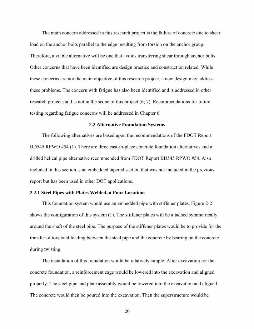
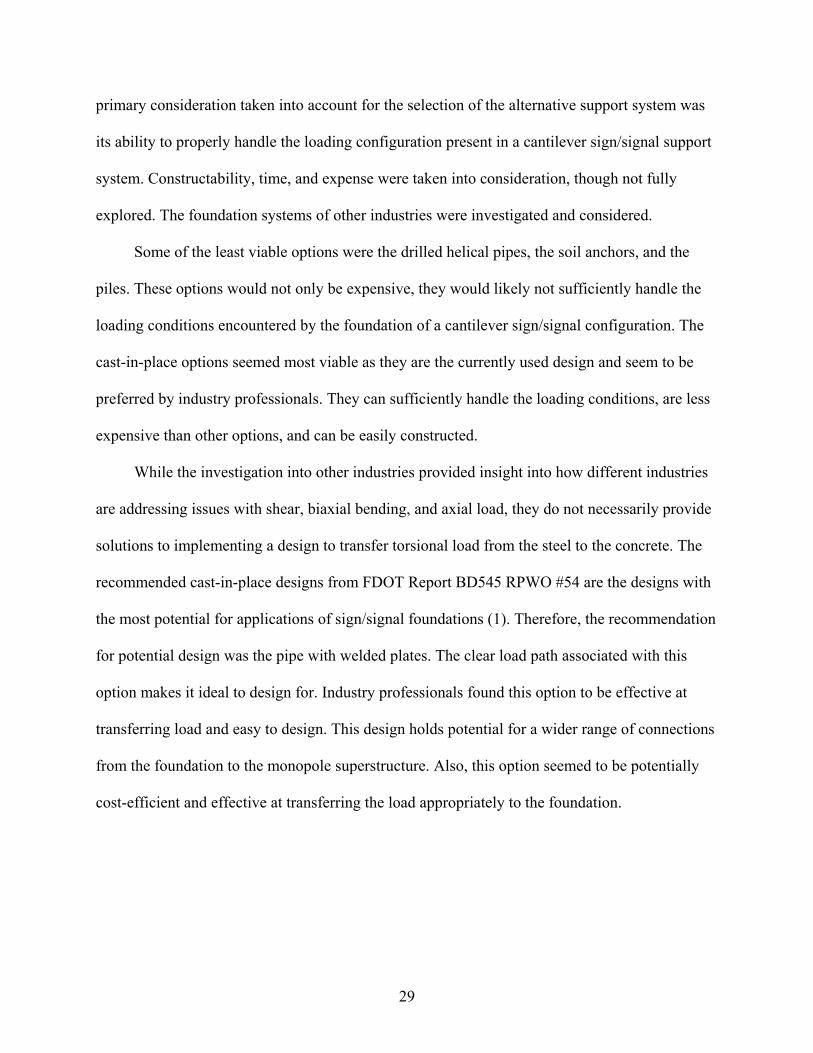
2.2.1 Steel Pipes with Plates Welded at Four Locations
This foundation system would use an embedded pipe with stiffener plates. Figure 2-2
shows the configuration of this system (1). The stiffener plates will be attached symmetrically
around the shaft of the steel pipe. The purpose of the stiffener plates would be to provide for the
transfer of torsional loading between the steel pipe and the concrete by bearing on the concrete
during twisting.
The installation of this foundation would be relatively simple. After excavation for the
concrete foundation, a reinforcement cage would be lowered into the excavation and aligned
properly. The steel pipe and plate assembly would be lowered into the excavation and aligned.
The concrete would then be poured into the excavation. Then the superstructure would be

21
erected on top of the foundation (8). The superstructure could be aligned and leveled using a
leveling nut detail shown in Figure 2-3. This connection would also eliminate problems with
grout installation because none would be required.
As mentioned earlier, the vertical torsional plates would act similar to an anchor group for
transferring load to the foundation. Figure 2-2 shows the possible force configuration that would
be acting on the foundation and how the foundation would resist the forces. Option A has an
annular plate welded to the bottom of the embedded pipe and plate section while option B does
not. The purpose of the annular plate is to provide a stiff member to resist the bending moment
induced on the foundation. If the plate were not a part of the configuration, then the pipe would
likely resist the bending by bearing on the concrete, creating a potential problem with buckling
of the pipe. As the biaxial moment acts on the foundation with the annular plate, it will induce a
tensile reaction on one part of the concrete foundation and a compressive reaction on the
opposite side, see Figure 2-2. The shear load will induce a distributed load on the sides of the
foundation. The axial load will be distributed throughout the foundation by the annular plate. The
torsional load will cause the stiffener plates to transfer the load as a shear force directed parallel
to the edge of the concrete similar to an anchor loaded in shear parallel to the edge and bear on
the concrete.
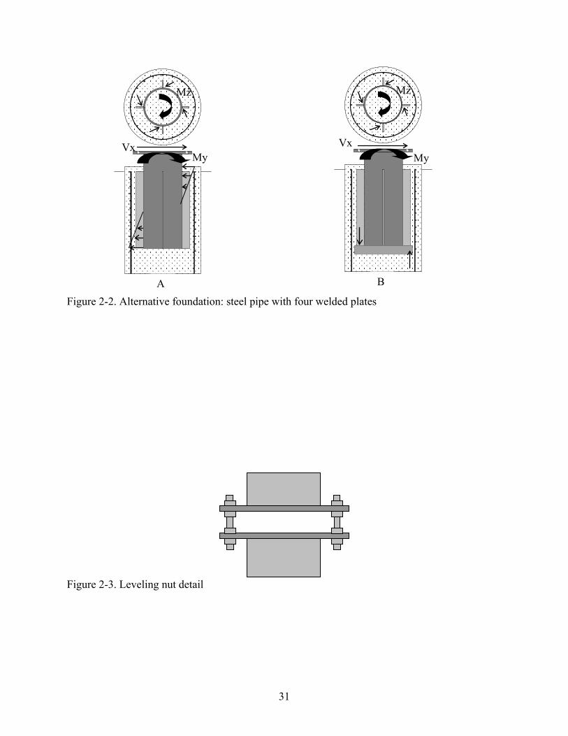
2.2.2 Geometric Hollow Section
This foundation would use an embedded geometric hollow section rather than a steel pipe.
Figure 2-4 shows the configuration of this system (1). The purpose of the geometric shape would
be to create additional torsional resistance through the geometry of the shape. The installation of
this foundation would be very similar to the method mentioned for the embedded pipe and plate
section.
22
The geometric shape of the pipe would act as the way to transfer the load from the steel
monopole to the concrete. The concrete would be able to resist the torsional rotation of the pipe
embedded in the foundation through the geometric advantages of the section. The shear force
would cause the concrete to resist as a distributed load. The moment would induce axial
resistance. Figure 2-4(b) shows the force configuration acting on the foundation and how it
would resist the force by bearing on the concrete.
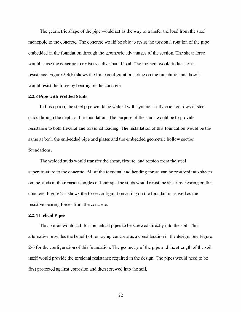
2.2.3 Pipe with Welded Studs
In this option, the steel pipe would be welded with symmetrically oriented rows of steel
studs through the depth of the foundation. The purpose of the studs would be to provide
resistance to both flexural and torsional loading. The installation of this foundation would be the
same as both the embedded pipe and plates and the embedded geometric hollow section
foundations.
The welded studs would transfer the shear, flexure, and torsion from the steel
superstructure to the concrete. All of the torsional and bending forces can be resolved into shears
on the studs at their various angles of loading. The studs would resist the shear by bearing on the
concrete. Figure 2-5 shows the force configuration acting on the foundation as well as the
resistive bearing forces from the concrete.
2.2.4 Helical Pipes
This option would call for the helical pipes to be screwed directly into the soil. This
alternative provides the benefit of removing concrete as a consideration in the design. See Figure
2-6 for the configuration of this foundation. The geometry of the pipe and the strength of the soil
itself would provide the torsional resistance required in the design. The pipes would need to be
first protected against corrosion and then screwed into the soil.

23
One possible drawback to this alternative would be that the helical piles would require
frequent field inspections to ensure that the soil is not failing. The helical piles would not be an
ideal option for Florida because of the prevalent poor soil conditions. Also, the helical piles
would be highly susceptible to corrosion because of the direct contact with the soil and possible
direct contact with the water table. In this foundation system, the load would not be transferred
from the steel to the concrete, but rather directly from the steel to the soil. Therefore a thorough
geotechnical assessment would be required before design could begin. Because of this, it would
be very difficult to present standard design guidelines for this option.
2.2.5 Embedded Geometric Tapered Section
In this option, a geometric tapered section would be embedded into the drilled shaft (See
Figure 2-7). The purpose of the geometric shape would be to create additional torsional
resistance through the geometric qualities of the shape. This foundation would require similar
construction methods as the other cast-in-place options.
The geometrically varied shape of the tapered section would act as the way to transfer the
load from the steel superstructure to the concrete. The concrete would be able to resist the
twisting motion of the pipe embedded in the foundation through the geometry of the section. The
shear force would cause the concrete to resist by bearing on the pipe in a distributed load. The
moment would induce axial resistance. One problem associated with this configuration is the
availability of large tapered sections to be embedded in the foundation. The large tapered
sections can be costly and difficult to find, limiting the practicality of this option.
2.3 Alternative Foundations from Other Industries
An investigation into transmission line foundations, cellular tower foundations, wind
turbine foundations, and large advertising sign foundations was completed. While investigating
these fields it became apparent that despite the similarities in foundation requirements, the large

24
torsion experienced by cantilever sign/signal foundations is not typically present in other
industries and is not designed for. Because of this, the other industries’ alternatives would most
likely not be viable for the cantilever sign and signal applications. The following section will
describe what was found in these other industries.
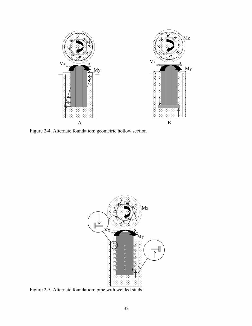
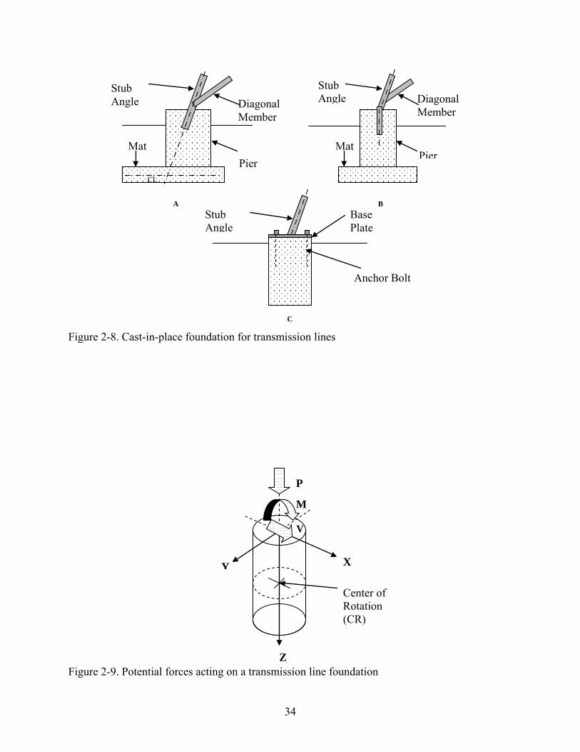
2.3.1 Transmission Line Foundations
An investigation into transmission line foundations showed that they often use cast-in-
place concrete designs that are similar to the current anchor bolt design, using anchor bolts to
connect the superstructure to the foundation; see Figure 2-8c (9). The other cast-in-place designs,
Figure 2-8a, Figure 2-8b, are disparate from the current anchor bolt design. However, these are
not viable alternative options because they are typically exposed to primarily axial and shear
loads. The sizes of the members make direct embedment a more suitable option for their
foundations than a cantilever sign/signal foundation. See Figure 2-9 for the loading that
transmission line foundations are subject to (9). This loading pattern is similar, but not the same
as the loading that cantilever sign/signal foundations are subject to. The torsional load that a
cantilever superstructure induces on a foundation creates additional concerns for transferring
load to the foundation that these foundations cannot address.
Other alternatives investigated in the transmission line industry seem unsuitable for
sign/signal foundations because of construction sequencing, cost, and most importantly because
they are unlikely to successfully transfer the torsional loading a sign/signal superstructure is
likely to induce. The following are examples of unsuitable alternatives found in the transmission
line industry:
• Drilled concrete piles, see Figure 2-10 (9) • Prestressed anchors • Grouted soil anchors

25
Drilled concrete piles are similar to the current anchor bolt design with the difference being
that the guys are embedded in the cast-in-place foundation instead of anchor bolts (See Figure 2-
10). These foundations handle axial, shear, and biaxial moments by transferring the loading from
the embedded guys to the concrete (9). However, because a transmission line tower is supported
by multiple legs, minimal torsional forces are present in each drilled concrete pile. Even the H-
structures and single pole structures do not introduce much torsional force into the foundation
because there is not a sufficient moment arm to produce significant torsional force. Figure 2-11
demonstrates the typical structural configurations of a lattice tower, H-structure, and single pole
structure as well as a cantilever sign/signal structure (9).
Prestressed and grouted soil anchors are typically not suitable to handle torsional load. As
described in the Institute for Electrical and Electronics Engineers (IEEE) Guide for Transmission
Structure Foundation and Testing, anchors are primarily used to provide resistance to tensile
forces (9). Prestressed anchors are typically expensive and should not be used in soils with time
dependent compressibility (9). These factors make them typically unsuitable to use for cantilever
sign/signal structures. See
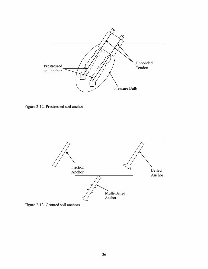
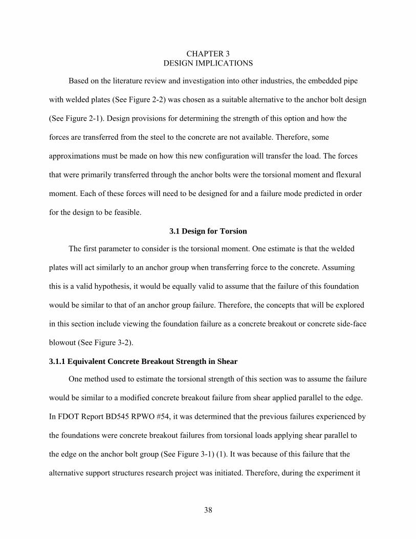
Figure 2-12 and Figure 2-13 for prestressed and grouted soil anchor configurations,
respectively.
Grouted soil anchors are designed to transfer uplift or tensile loads from the superstructure
directly to the soil (9). They do this through frictional resistance between the grout and soil, as
well as through the end bearing strength from the increased diameter at the end of the anchor (9).
However, the anchors do not provide much torsional resistance because of their smooth
geometry.
26
Despite the fact that these are viable alternatives in the field of transmission line
foundations, these are generally not preferable options for sign and signal foundation systems.
The fact that sign and signal installations are sequenced at the end of highway construction make
piles and anchors undesirable options. By the time the contractor is installing signs and signals,
most of the large pile-driving equipment has been moved off the construction site and would
create additional expense for the contractor. Time and expense are also reasons why these
options are not preferred. Prestressed anchors and grouted soil anchors require geotechnical
expertise as well as significant geotechnical analysis of the area and would need to be designed
for individual projects which can be more costly. It would be difficult to produce a standard for
these options.
2.3.2 Wind Turbine Foundations
The search into wind turbine foundations was initially promising, being that they are
required to handle significant amounts of lateral force from the wind (10). However, the torsion
experienced by a wind turbine is not significant because there is a limited moment arm. Of
greater concern for a wind turbine is biaxial moments. Thus, the three primary designs for a
monopole wind turbine that were specified included a mat foundation, a pad and pier foundation,
and a pier foundation, all of which utilize anchor bolts to connect the superstructure to the
foundation (11). There were guyed tower options as well, but these were not explored thoroughly
because of their irrelevance to this project’s application and their similarity to the transmission
line industry’s guyed tower foundations.
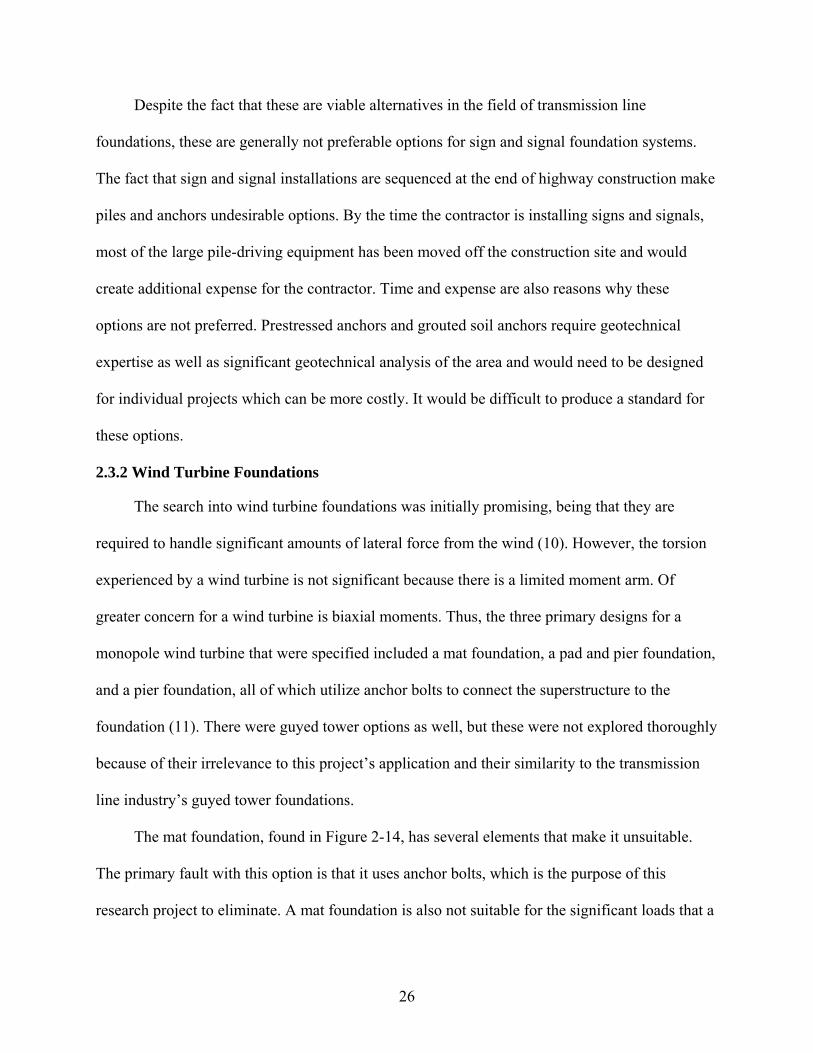
The mat foundation, found in Figure 2-14, has several elements that make it unsuitable.
The primary fault with this option is that it uses anchor bolts, which is the purpose of this
research project to eliminate. A mat foundation is also not suitable for the significant loads that a
27
cantilever sign/signal structure will induce on a foundation. The uplift that is created by the
cantilever structure will necessitate a deeper foundation.
The pad and pier foundation, found in Figure 2-15, and the pier alone foundations are
similar to the current anchor bolt design. They are cast-in-place concrete foundations with a
monopole attached to the foundation by anchor bolts. The pad and pier foundation is the same as
the current anchor bolt design. These options do not hold any potential for a new design because
they are the same as the current anchor bolt design. The loading configuration on a wind turbine
is similar to that of the transmission line structures. While the wind turbine and transmission line
structures will exceed the height of the cantilever sign/signal structure, they do not have
sufficient moment arms to create a torsion that is equivalent to the torsion experienced in a
cantilever sign/signal structure.
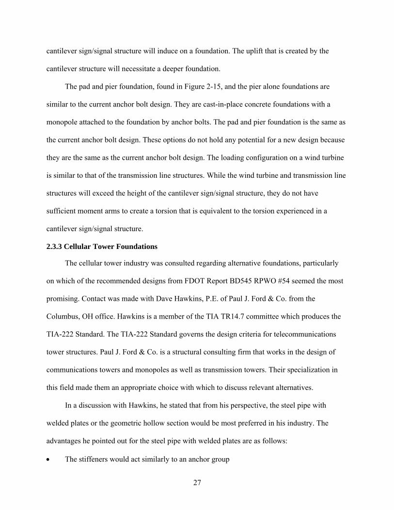
2.3.3 Cellular Tower Foundations
The cellular tower industry was consulted regarding alternative foundations, particularly
on which of the recommended designs from FDOT Report BD545 RPWO #54 seemed the most
promising. Contact was made with Dave Hawkins, P.E. of Paul J. Ford & Co. from the
Columbus, OH office. Hawkins is a member of the TIA TR14.7 committee which produces the
TIA-222 Standard. The TIA-222 Standard governs the design criteria for telecommunications
tower structures. Paul J. Ford & Co. is a structural consulting firm that works in the design of
communications towers and monopoles as well as transmission towers. Their specialization in
this field made them an appropriate choice with which to discuss relevant alternatives.
In a discussion with Hawkins, he stated that from his perspective, the steel pipe with
welded plates or the geometric hollow section would be most preferred in his industry. The
advantages he pointed out for the steel pipe with welded plates are as follows:
• The stiffeners would act similarly to an anchor group

28
• Relatively easily cast-in-place • No direct contact between the steel and soil, reducing corrosion issues
Some possible problems with this configuration are mostly construction related. If the
substructure is not placed properly, then the superstructure would not align levelly. This is a
concern with the current anchor bolt design, and will be a concern in most cast-in-place designs.
The current anchor bolt method uses leveling nuts, as seen in Figure 2-3, to properly align the
monopole with the foundation.
The geometric hollow section is also a preferred option for the cellular tower monopole
industry because they currently use 12-sided, 16-sided, and 18-sided poles. Hawkins explained
that any relevant research pertaining to these designs has not been conducted yet and would be
very useful to the telecommunications industry.
2.3.4 Advertising Monopole Foundations
For standards pertaining to monopole foundations in the advertising industry, the
International Sign Association (ISA) was contacted. Contact was made with Bill Dundas, who is
the ISA’s Director of Technical Affairs. Given FDOT Report BD545 RPWO #54, Dundas
forwarded this information to the ISA’s Mechanical and Structural Subcommittee to make
comments and recommendations on preferences from the options selected in FDOT Report
BD545 RPWO #54 as well as suggest any additional designs. Based on the information gathered
from ISA’s Mechanical and Structural Subcommittee, the pipe with welded studs seemed to be a
preferred option. The subcommittee commented that this detail had been used in larger pipes
from 48 inches to 96 inches in diameter.
2.4 Selection
The purpose of the literature review and investigation into alternative support structures
was to identify viable foundation alternatives on which to conduct an experimental program. The
29
primary consideration taken into account for the selection of the alternative support system was
its ability to properly handle the loading configuration present in a cantilever sign/signal support
system. Constructability, time, and expense were taken into consideration, though not fully
explored. The foundation systems of other industries were investigated and considered.
Some of the least viable options were the drilled helical pipes, the soil anchors, and the
piles. These options would not only be expensive, they would likely not sufficiently handle the
loading conditions encountered by the foundation of a cantilever sign/signal configuration. The
cast-in-place options seemed most viable as they are the currently used design and seem to be
preferred by industry professionals. They can sufficiently handle the loading conditions, are less
expensive than other options, and can be easily constructed.
While the investigation into other industries provided insight into how different industries
are addressing issues with shear, biaxial bending, and axial load, they do not necessarily provide
solutions to implementing a design to transfer torsional load from the steel to the concrete. The
recommended cast-in-place designs from FDOT Report BD545 RPWO #54 are the designs with
the most potential for applications of sign/signal foundations (1). Therefore, the recommendation
for potential design was the pipe with welded plates. The clear load path associated with this
option makes it ideal to design for. Industry professionals found this option to be effective at
transferring load and easy to design. This design holds potential for a wider range of connections
from the foundation to the monopole superstructure. Also, this option seemed to be potentially
cost-efficient and effective at transferring the load appropriately to the foundation.

30
Table 2-1. Support structure foundation frequency of use(7)
Structure type Reinforced Cast-In-
Place Drilled Shafts
Unreinforced Cast-In-
Place Drilled Shafts
Steel Screw-In
Foundation
Spread Footings
Directly Embedded
Overhead Cantilever Common None Rare Intermediate None Over Head Bridge Intermediate None Rare Intermediate None Road Side Sign Intermediate Rare Rare Rare Rare Street Light Poles Intermediate Rare Rare Rare Rare High-Level Lighting Poles
Common None None Rare None
Traffic Signal Supports
Common None None Rare Rare
Span Wire Supports Intermediate None None Rare Rare Notation Common = 67-100% of the states reporting use Intermediate = 34-66% of the states reporting use Rare = 1-33% of the states reporting use None = 0% of the states reporting use
Figure 2-1. How torsional and flexural moments are transferred using anchor bolts(1)
Flexure Resolved into Tension and Compression
Torsion Resolved into Shear Parallel
to the Edge
Concrete Cracking
Applied Torsion
Applied Flexure
31
Figure 2-2. Alternative foundation: steel pipe with four welded plates
Figure 2-3. Leveling nut detail
B
Mz
Vx My
A
Mz
Vx My
32
Figure 2-4. Alternate foundation: geometric hollow section
Figure 2-5. Alternate foundation: pipe with welded studs
Mz
Vx My
B
Mz
Vx My
A
Mz
My Vx

33
Figure 2-6. Alternate foundation: helical pipes
Figure 2-7. Alternate foundation: geometric tapered section
34
Figure 2-8. Cast-in-place foundation for transmission lines
Figure 2-9. Potential forces acting on a transmission line foundation
Center of Rotation (CR)
Z
Y X
P
M
V
A
Stub Angle Diagonal
Member
Pier CL
Mat
Diagonal Member
Pier Mat
Stub Angle
B
Anchor Bolt
Stub Angle
Base Plate
C

35
Figure 2-10. Drilled concrete piles for transmission lines
Figure 2-11. Typical transmission line structures compared to a cantilever sign structure
Lattice Tower Single Pole Structure
H-Structure Cantilever Sign
Battered Shaft
Bell
Straight Shaft
36
Figure 2-12. Prestressed soil anchor
Figure 2-13. Grouted soil anchors
Friction Anchor Belled
Anchor
Multi-Belled Anchor
Unbonded Tendon
Pressure Bulb
Prestressed soil anchor

37
Figure 2-14. Mat foundation for wind turbines
Figure 2-15. Pad and pier foundations for wind turbines
38
CHAPTER 3 DESIGN IMPLICATIONS
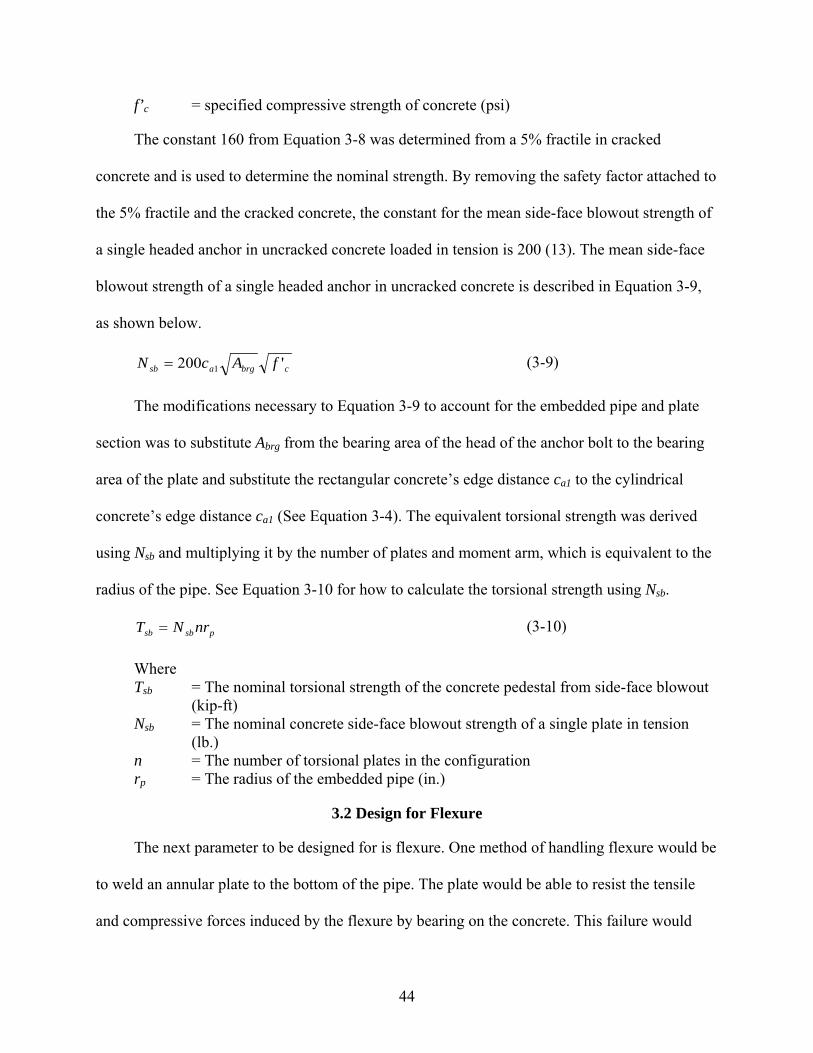
Based on the literature review and investigation into other industries, the embedded pipe
with welded plates (See Figure 2-2) was chosen as a suitable alternative to the anchor bolt design
(See Figure 2-1). Design provisions for determining the strength of this option and how the
forces are transferred from the steel to the concrete are not available. Therefore, some
approximations must be made on how this new configuration will transfer the load. The forces
that were primarily transferred through the anchor bolts were the torsional moment and flexural
moment. Each of these forces will need to be designed for and a failure mode predicted in order
for the design to be feasible.
3.1 Design for Torsion
The first parameter to consider is the torsional moment. One estimate is that the welded
plates will act similarly to an anchor group when transferring force to the concrete. Assuming
this is a valid hypothesis, it would be equally valid to assume that the failure of this foundation
would be similar to that of an anchor group failure. Therefore, the concepts that will be explored
in this section include viewing the foundation failure as a concrete breakout or concrete side-face
blowout (See Figure 3-2).
3.1.1 Equivalent Concrete Breakout Strength in Shear
One method used to estimate the torsional strength of this section was to assume the failure
would be similar to a modified concrete breakout failure from shear applied parallel to the edge.
In FDOT Report BD545 RPWO #54, it was determined that the previous failures experienced by
the foundations were concrete breakout failures from torsional loads applying shear parallel to
the edge on the anchor bolt group (See Figure 3-1) (1). It was because of this failure that the
alternative support structures research project was initiated. Therefore, during the experiment it

39
would be useful to determine the equivalent torsional strength from concrete breakout and design
the rest of the test to preclude other failure modes. In order to calculate an estimated strength of
the concrete breakout, the anchor breakout equations need to be modified to account for the
differences between an anchor breakout and the pipe and plate breakout.
An anchor breakout failure occurs at the surface of the concrete in which it is installed,
typically with a ≈35° breakout failure cone. The embedded pipe and stiffener configuration
would cause the stiffeners to cause a similar ≈35° breakout failure cone, though not at the top of
the shaft. The breakout would occur where the plates are embedded in the concrete. As a result
of this expected concrete breakout, the breakout surface would be considerably larger than that
of a typical concrete breakout for an anchor loaded in shear because it will create a breakout
cone in both the top and bottom of the welded plate. Figure 3-2 depicts the differences between
the typical anchor concrete breakout and the expected breakout caused by the welded plates.
In order to quantify the difference in these breakout configurations, some manipulation of
the governing equations for concrete breakout of an anchor loaded in shear from ACI 318-08
Appendix D (5) will be required. First, the breakout strength of an anchor loaded in shear needs
to be described. The basic breakout strength of a single anchor in cracked concrete loaded in
shear perpendicular to an edge (See Figure 3-3) is described in ACI 318-08 Equation D-24 and is
shown below as Equation 3-1 (5).
( ) 5.11
2.0
7 acaa
eb cfd
dV ′
= λ
(3-1)
Where Vb = basic concrete breakout strength in shear of a single anchor in cracked
concrete (lb.) e = load bearing length of anchor for shear (in.) da = outside diameter of anchor (in.) λ = 1.0 for normal weight concrete f’c = specified compressive strength of concrete (psi)

40
ca1 = distance from the center of an anchor shaft to the edge of concrete in one direction; taken in the direction of the applied shear (in.)
The maximum length for e is limited to 8da as delineated in ACI 318-08 D6.2.2. The
constant 7 from Equation 3-1 was determined from a 5% fractile with cracked concrete. The
constant 7 becomes a constant 13 for the mean breakout strength of a single anchor in uncracked
concrete loaded in shear perpendicular to the edge. The mean breakout strength is described in
Equation 3-2, as shown below (12).
( ) 5.11
2.0
13 acaa
eb cfd
dV ′
= λ
(3-2)
ACI 318-08 (5) describes the nominal breakout strength of an anchor loaded in shear
perpendicular to the edge in Equation D-21 and is described below as Equation 3-3. Figure 3-4
depicts the projected concrete failure area of a single anchor in rectangular concrete. Figure 3-5
depicts the projected concrete failure area of a single anchor in cylindrical concrete. An
important distinction to note between the failure area of a single anchor in rectangular concrete
and cylindrical concrete is the edge distance ca1. Equation 3-4 details how to calculate the value
of ca1 for an anchor adjacent to a circular edge.
bVhVcVedVco
Vcbc V
AA
V ,,, ψψψ= (3-3)
Where Vcb = The nominal concrete breakout strength in shear of a single anchor (lb.) AVc = The projected area of the failure surface for a single or group of anchors,
used to determine the shear strength (in2) AVco = The projected concrete failure area of a single anchor, for calculation of
strength in shear, if not limited by corner influences, spacing, or member thickness (in.2)
= 4.5(ca1)2, based on an ≈35° failure cone (Figure 2-16) ψed,V = The factor used to modify shear strength of anchors for edge effects, ACI
318-08 Section D.6.2.6 ψc,,V = The factor used to modify shear strength of anchors based on presence or
absence of cracks in concrete and presence or absence of supplementary reinforcement, ACI 318-08 Section D.6.2.7, accounted for in Equation 2-2

41
ψh,V = The factor used to modify shear strength of anchors based on anchor location and effective length of anchor, ACI 318-08 Section D.6.2.8
( ) ( ) ( )[ ]25.3
25.3 222
1bbsb
a
rrrrc
−−+= (3-4)
Where ca1 = distance from the center of an anchor shaft to the edge of concrete in one
direction; taken in the direction of the applied shear (in.) rb = The distance from the center of the cylindrical shaft to the center of the anchor
bolt (in.) rs = The radius of the cylindrical shaft (in.)
As FDOT Report BD545 RPWO #54 determined, the failure loading on the foundation’s
anchor group was torsion (1). This torsion can be resolved into shear forces acting parallel to an
edge. ACI 318-08 prescribes in section D6.2.1 that the nominal concrete breakout strength of a
single anchor loaded in shear parallel to an edge shall be permitted to be twice the value of the
shear force determined as Vcb, which assumes shear loading perpendicular to an edge.
Now that the basic equations for concrete breakout due to shear on anchor bolts have been
established, it is appropriate to address the changes in these equations to satisfy the differences
between the anchor breakout and the expected experimental breakout. The mean breakout
strength of a single plate in shear acting perpendicular to the edge has been modified from
Equation 3-2 to Equation 3-5 listed below by substituting the geometric qualities from the anchor
bolt system to the appropriate geometric qualities of the embedded pipe and plate system..
( ) 5.11
2.0
13 acpp
eb cft
tV ′
= λ
(3-5)
Where Vb = basic concrete breakout strength in shear of a single plate in uncracked
concrete (lb.) e = load bearing length of plate for shear (in.) tp = thickness of plate (in.) ca1 = distance from the center of the plate to the edge of concrete in one
direction; taken in the direction of the applied shear (in.)

42
The arrangement of the plates in this specific design does not allow them to be analyzed as
a group because their ≈35° breakout failure cones do not overlap. Therefore, Equation 3-3 was
utilized to determine the strength of a single plate. However, the Avcp, or the projected area of the
breakout surface for a single plate, was modified from Avc to account for the differences in the
breakout surface. Figure 3-6 depicts the area AVcp.
Because the concrete breakout area for the plate is much larger than that of the anchor bolt,
the ratio of the plate breakout area to the anchor bolt breakout area will include the increase in
breakout strength for the plate due to the larger breakout area. There will be an increase in
strength because it will take more force to cause a breakout on a larger volume of concrete.
Equation 3-6 accounts for the additional strength of a concrete breakout for the embedded plate
because the ratio of AVcp to AVco will be greater than one as can be seen by comparing Figure 3-5
and Figure 3-6. Equation 3-6 displays the equation utilized to determine the concrete breakout
strength of a single plate.
bVhVcVedVco
Vcpbpc V
AA
V ,,, ψψψ= (3-6)
Where Vcbp = The nominal concrete breakout strength in shear of a single plate (lb.) AVcp = The projected area of the failure surface for a single plate, used to
determine the shear strength (in2) =3.0ca1*(3.0ca1 + lpl) AVco = projected concrete failure area of a single anchor, for calculation of
strength in shear, if not limited by corner influences, spacing, or member thickness (in.2)
= 4.5(ca1)2, based on an ≈35° failure cone (Figure 3-4)
The contribution of each plate to the overall torsional strength of the embedded pipe (Tcbp)
is twice the expected breakout strength (Vcbp) multiplied by the moment arm. It is twice the
expected breakout strength because as mentioned earlier, the shear strength when loaded parallel
to the edge of concrete is permitted to be twice that of the shear strength when loaded

43
perpendicular to the edge of concrete and Equations 3-5 and 3-6 are for loading perpendicular to
the edge of concrete.
pcbpbpc nrVT 2= (3-7)
Where Tcbp = The nominal torsional strength of the pedestal from concrete breakout (kip-ft) Vcbp = The nominal concrete breakout strength in shear of plate configuration
where the plates are not acting as a group (lb.) n = The number of torsional plates in the configuration; the plates are not acting in a
group rp = The radius of the pipe (in.)
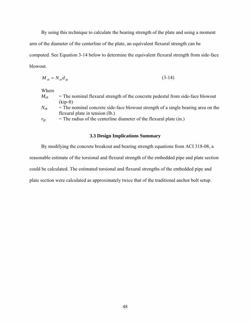
3.1.2 Equivalent Side-Face Blowout Strength
Another method to determine the torsional strength of the embedded pipe and plate section
is to determine the available bearing strength of concrete for the embedded pipe and plate
section. The bearing strength was expected to be calculated similarly to the side-face blowout
strength of a headed anchor in tension. The side-face blowout strength of a headed anchor in
tension represents the bearing strength of the concrete at the head of the anchor. Figure 3-7
depicts the similarities in anticipated failure cones for the embedded pipe and plate section and
the headed anchor configuration.
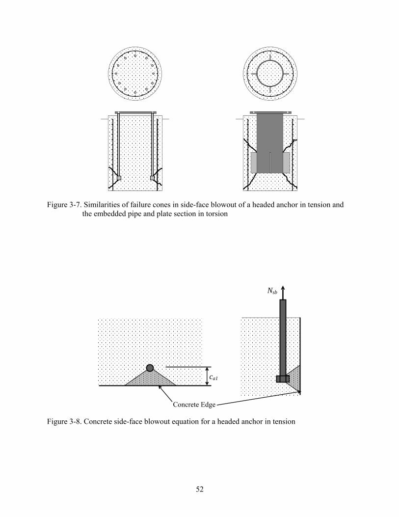
The similarity in these failures shows that there requires little manipulation of the equation
to determine the bearing strength for the embedded pipe and plate section. ACI 318-08 Appendix
D determines the nominal side-face blowout strength of a headed anchor in tension (See Figure
3-8) in Equation D-17 and is shown below as Equation 3-8.
cbrgasb fAcN '160 1= (3-8)
Where Nsb = the nominal concrete side-face blowout strength of a single headed
anchor in tension (lb.) ca1 = distance from the center of an anchor shaft to the edge of concrete in one
direction; taken in the direction of the closest edge (in.) Abrg = bearing area of the head of anchor bolt (in.2)
44
f’c = specified compressive strength of concrete (psi)
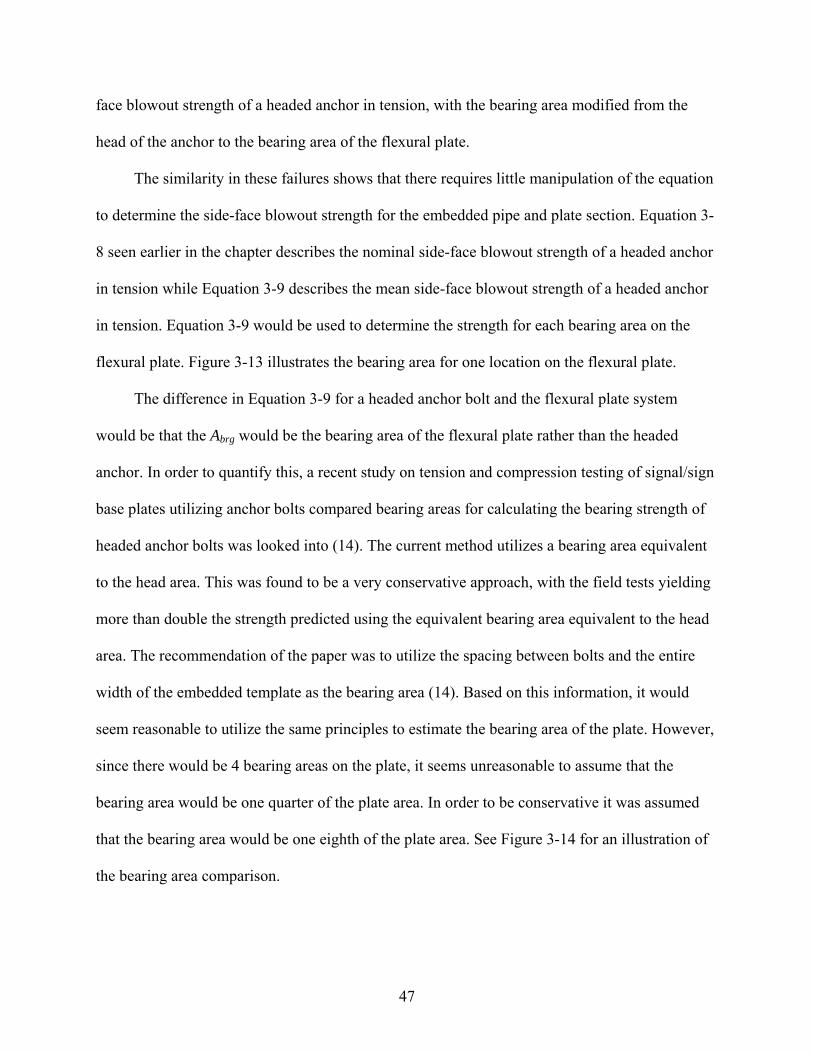
The constant 160 from Equation 3-8 was determined from a 5% fractile in cracked
concrete and is used to determine the nominal strength. By removing the safety factor attached to
the 5% fractile and the cracked concrete, the constant for the mean side-face blowout strength of
a single headed anchor in uncracked concrete loaded in tension is 200 (13). The mean side-face
blowout strength of a single headed anchor in uncracked concrete is described in Equation 3-9,
as shown below.
cbrgasb fAcN '200 1= (3-9)
The modifications necessary to Equation 3-9 to account for the embedded pipe and plate
section was to substitute Abrg from the bearing area of the head of the anchor bolt to the bearing
area of the plate and substitute the rectangular concrete’s edge distance ca1 to the cylindrical
concrete’s edge distance ca1 (See Equation 3-4). The equivalent torsional strength was derived
using Nsb and multiplying it by the number of plates and moment arm, which is equivalent to the
radius of the pipe. See Equation 3-10 for how to calculate the torsional strength using Nsb.
psbsb nrNT = (3-10)
Where Tsb = The nominal torsional strength of the concrete pedestal from side-face blowout
(kip-ft) Nsb = The nominal concrete side-face blowout strength of a single plate in tension
(lb.) n = The number of torsional plates in the configuration rp = The radius of the embedded pipe (in.)
3.2 Design for Flexure
The next parameter to be designed for is flexure. One method of handling flexure would be
to weld an annular plate to the bottom of the pipe. The plate would be able to resist the tensile
and compressive forces induced by the flexure by bearing on the concrete. This failure would

45
also produce a concrete breakout or side-face blowout that can also be compared to an anchor
bolt failure.
3.2.1 Equivalent Concrete Breakout Strength in Shear
One method of hypothesizing the predicted behavior of the embedded section would be to
treat it as a typical annular base plate with anchor bolts. When analyzing flexure on this setup,
the flexure can be resolved into a compressive force on one side of the plate and a tensile force
on the other side of the flexural plate (See Figure 3-10). The resolved forces can be viewed to act
in one of two ways: shear parallel to an edge and an equivalent bearing pressure causing side-
face blowout. In this section the hypothetical failure mode associated with shear parallel to the
edge will be discussed.
As shown in Figure 3-10, the flexural moment can be resolved into a tension and
compression acting on opposite sides of the plate. Another way of looking at the tension and
compression forces would be to rotate the foundation 90 degrees to more clearly see it as shear
acting parallel to an edge (See Figure 3-11). These shears will create a breakout failure similar to
that experienced during torsional loading on the welded plates. Modifying Equation 3-2 to
account for the differences in the anchor bolt configuration and the embedded pipe and plate
configuration yields Equation 3-11, shown below.
( ) 5.11
2.0
13 acfpfp
ebfp cfb
tV ′
= λ
(3-11)
Where Vbfp = the basic concrete breakout strength in shear of one side of a flexural plate in
cracked concrete (lb.) e = the equivalent bearing length of the annular plate, taken conservatively as 1/8 of
the circumference of the centerline of the plate (in.) tfp = the thickness of the annular plate (in.) bfp = the bearing width of the annular plate (in.) f’c = specified compressive strength of concrete (psi)

46
ca1 = the edge distance, taken from the center of the width of the plate to the nearest concrete edge (in.)
Once the basic concrete breakout strength of one plate bearing area has been determined,
then the total shear breakout capacity can be determined using Equation 3-12. Equations 3-11
and 3-12 are used to determine the shear strength perpendicular to an edge. To determine the
shear strength parallel to an edge, the perpendicular shear strengths obtained need to be doubled.
See Figure 3-12 for a visual representation of the values in Equations 3-11 and 3-12.
bfpVhVcVedVco
Vcpbfpc V
AA
V ,,, ψψψ= (3-12)
Where Vcbfp = The nominal concrete breakout strength in shear of plate configuration
where the plate bearing areas are not acting as a group (lb.) AVcfp = The projected area of the failure surface for a single bearing location on the
plate, used to determine the shear strength (in2) =(3.0ca1+ le)*(3.0ca1 + tfp) AVco = projected concrete failure area of a single anchor, for calculation of
strength in shear, if not limited by corner influences, spacing, or member thickness (in.2)
= 4.5(ca1)2, based on an ≈35° failure cone (Figure 3-4)
Using the value obtained from Equation 3-12, an equivalent flexural strength can be
calculated using Equation 3-13.
fpcbfpbfpc dVM 2= (3-13)
Where Mcbfp = The nominal flexural concrete breakout strength in shear of plate configuration
where the plate bearing areas are not acting as a group (lb.) Vcbfp = The nominal concrete breakout strength in shear of plate configuration where
the plate bearing areas are not acting as a group (lb.) dfp = The diameter of the centerline of the flexural plate (in.)
3.2.2 Equivalent Side-Face Blowout Strength
The other method to determine the flexural strength of the embedded pipe and plate section
is to determine the available side-face blowout strength of concrete for the embedded pipe and
plate section. The side-face blowout strength was expected to be calculated similarly to the side-
47
face blowout strength of a headed anchor in tension, with the bearing area modified from the
head of the anchor to the bearing area of the flexural plate.
The similarity in these failures shows that there requires little manipulation of the equation
to determine the side-face blowout strength for the embedded pipe and plate section. Equation 3-
8 seen earlier in the chapter describes the nominal side-face blowout strength of a headed anchor
in tension while Equation 3-9 describes the mean side-face blowout strength of a headed anchor
in tension. Equation 3-9 would be used to determine the strength for each bearing area on the
flexural plate. Figure 3-13 illustrates the bearing area for one location on the flexural plate.
The difference in Equation 3-9 for a headed anchor bolt and the flexural plate system
would be that the Abrg would be the bearing area of the flexural plate rather than the headed
anchor. In order to quantify this, a recent study on tension and compression testing of signal/sign
base plates utilizing anchor bolts compared bearing areas for calculating the bearing strength of
headed anchor bolts was looked into (14). The current method utilizes a bearing area equivalent
to the head area. This was found to be a very conservative approach, with the field tests yielding
more than double the strength predicted using the equivalent bearing area equivalent to the head
area. The recommendation of the paper was to utilize the spacing between bolts and the entire
width of the embedded template as the bearing area (14). Based on this information, it would
seem reasonable to utilize the same principles to estimate the bearing area of the plate. However,
since there would be 4 bearing areas on the plate, it seems unreasonable to assume that the
bearing area would be one quarter of the plate area. In order to be conservative it was assumed
that the bearing area would be one eighth of the plate area. See Figure 3-14 for an illustration of
the bearing area comparison.
48
By using this technique to calculate the bearing strength of the plate and using a moment
arm of the diameter of the centerline of the plate, an equivalent flexural strength can be
computed. See Equation 3-14 below to determine the equivalent flexural strength from side-face
blowout.
fpsbsb dNM = (3-14)
Where Msb = The nominal flexural strength of the concrete pedestal from side-face blowout
(kip-ft) Nsb = The nominal concrete side-face blowout strength of a single bearing area on the
flexural plate in tension (lb.) rfp = The radius of the centerline diameter of the flexural plate (in.)
3.3 Design Implications Summary
By modifying the concrete breakout and bearing strength equations from ACI 318-08, a
reasonable estimate of the torsional and flexural strength of the embedded pipe and plate section
could be calculated. The estimated torsional and flexural strengths of the embedded pipe and
plate section were calculated as approximately twice that of the traditional anchor bolt setup.

49
Figure 3-1. Concrete breakout of an anchor caused by shear directed parallel to the edge for a
cylindrical foundation
Figure 3-2. Differences between concrete breakout failures for anchor bolts in shear and
embedded pipe and plate section in torsion
Figure 3-3. Concrete breakout formula for an anchor loaded in shear1
Vb
ca1
Vb
Concrete Edge

50
Figure 3-4. Shear breakout of a single anchor in rectangular concrete
Figure 3-5. Shear breakout for a single anchor in cylindrical concrete
Vb
ca1 ≈35°
1.5ca1 1.5ca1
Vb
≈35°
1.5ca1
AVco
1.5ca1 1.5ca1
1.5ca1 AVco=1.5ca1·2(1.5ca1) =4.5(ca1)2
ca1
ca1
1.5ca1 ≈35°
≈35°
1.5ca1
1.5ca1
1.5ca1 1.5ca1
1.5ca1
AVco

51
Figure 3-6. Determination of AVcp based on ≈35° failure cone for embedded pipe and plate
section
3.0ca1+lpl
≈35° Vb
ca1
lpl
AVcp = 3.0ca1 * (3.0ca1 + lpl)
AVcp
1.5ca1 1.5ca1 3.0ca1+lpl
≈35°
1.5ca1 1.5ca1
ca1 ≈35°
52
Figure 3-7. Similarities of failure cones in side-face blowout of a headed anchor in tension and the embedded pipe and plate section in torsion
Figure 3-8. Concrete side-face blowout equation for a headed anchor in tension
ca1
Nsb
Concrete Edge

53
Figure 3-9. Schematic of anticipated failure and bearing area of torsion plate
Figure 3-10. Flexure resolved into a tension and compression on an anchor bolt system and the
proposed system
ca1 Abrg

54
Figure 3-11. The tensile and compressive forces seen as shears acting parallel to an edge
Figure 3-12. Determination of AVcfp based on ≈35° failure cone for embedded pipe and plate
section
3.0ca1+tfp 1.5ca1 1.5ca1
ca1
ca1
AVcfp = (3.0ca1+le) * (3.0ca1 + tfp) 3.0ca1+tfp
≈35°
le
1.5ca1 1.5ca1
AVcp
le
≈35°
Vbfp
Vbfp
Vt
Vc
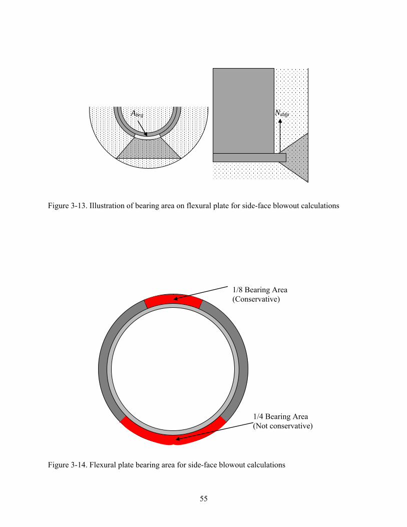
55
Figure 3-13. Illustration of bearing area on flexural plate for side-face blowout calculations
Figure 3-14. Flexural plate bearing area for side-face blowout calculations
1/8 Bearing Area (Conservative)
1/4 Bearing Area (Not conservative)
Abrg Nsbfp
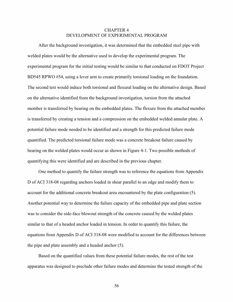
56
CHAPTER 4 DEVELOPMENT OF EXPERIMENTAL PROGRAM
After the background investigation, it was determined that the embedded steel pipe with
welded plates would be the alternative used to develop the experimental program. The
experimental program for the initial testing would be similar to that conducted on FDOT Project
BD545 RPWO #54, using a lever arm to create primarily torsional loading on the foundation.
The second test would induce both torsional and flexural loading on the alternative design. Based
on the alternative identified from the background investigation, torsion from the attached
member is transferred by bearing on the embedded plates. The flexure from the attached member
is transferred by creating a tension and a compression on the embedded welded annular plate. A
potential failure mode needed to be identified and a strength for this predicted failure mode
quantified. The predicted torsional failure mode was a concrete breakout failure caused by
bearing on the welded plates would occur as shown in Figure 4-1. Two possible methods of
quantifying this were identified and are described in the previous chapter.
One method to quantify the failure strength was to reference the equations from Appendix
D of ACI 318-08 regarding anchors loaded in shear parallel to an edge and modify them to
account for the additional concrete breakout area encountered by the plate configuration (5).
Another potential way to determine the failure capacity of the embedded pipe and plate section
was to consider the side-face blowout strength of the concrete caused by the welded plates
similar to that of a headed anchor loaded in tension. In order to quantify this failure, the
equations from Appendix D of ACI 318-08 were modified to account for the differences between
the pipe and plate assembly and a headed anchor (5).
Based on the quantified values from these potential failure modes, the rest of the test
apparatus was designed to preclude other failure modes and determine the tested strength of the
57
pipe and plate assembly in order to develop design guidelines. This chapter elaborates on the
development of the experimental test program.
As a side note, in both torsion and flexure, the predicted concrete breakout strength was
less than the predicted side-face blowout strength. These strengths were utilized to determine the
required strengths of the remainder of the test apparatus. Therefore, if the nominal strength of a
portion of the test design did not exceed the predicted side-face blowout strength, yet exceeded
the predicted concrete breakout strength, it was deemed sufficient.
4.1 Description of Test Apparatus
The test from FDOT Report BD545 RPWO #54 was designed to be a half-size model of
field conditions for testing at the Florida Department of Transportation (FDOT) Structures
Research Center. Therefore, the starting point for this test was to design the concrete shaft the
same size as the half-size model from the previous report. During design of the first test, the
concrete shaft was modified from the original half-size design of a 30” diameter to a 26”
diameter to reduce the capacity of the concrete shaft so that the previously fabricated lever arm
would be sufficient for the test. This process will be described in detail in the subsequent
sections. The second test that was conducted for flexure and torsion was designed using the
original half-size design of a 30” diameter. A schematic of the torsion test apparatus is shown in
Figure 4-2. A schematic of the flexure and torsion test apparatus is shown in Figure 4-3. The
final design for the torsion test apparatus consisted of the following:
• A 26” diameter concrete shaft that extended 3’-0” outward from the concrete block
• A 16” diameter steel pipe assembly with 4 welded 1” x 1” x 7” steel plates
• The 16” diameter embedded pipe assembly welded to a 24” diameter, 1” thick steel base plate with 12-1.75” diameter holes drilled for the anchor bolts to provide the connection this lever arm assembly and the embedded pipe assembly
• A 16” diameter, 10’-0” long steel pipe lever arm assembly

58
• Twelve 4.5” long, 1.5” diameter A490 bolts and associated nuts and washers to connect the lever arm assembly and the embedded pipe assembly
• A 6’-0” x 10’-0’ x 2’-6” reinforced concrete block to provide a fixed support at the base of the concrete shaft
• Two assemblies of C12x30 steel channels and plates to attach the block to the floor
The final design for the torsion and flexure test apparatus consisted of the following:
• A 30” diameter concrete shaft that extended 3’-0” outward from the concrete block
• A 16” diameter steel pipe assembly with 4 welded 1” x 1” x 7” steel plates and a welded 20” outside diameter annular plate
• A 16” diameter, 10’-0” long steel pipe lever arm assembly
• A 16” diameter, 7’-0” long steel extension pipe assembly
• The 16” diameter embedded pipe assembly was also welded to a 24” diameter, 1” thick steel base plate with 12-1.75” diameter holes drilled for bolts to provide the connection between this embedded pipe assembly and the lever arm assembly
• 12- 4.5” long, 1.5” diameter A490 bolts and associated nuts and washers to connect the extension pipe assembly and the embedded pipe assembly
• An additional 12-4.5” long, 1.5” diameter A490 bolts and associated nuts and washers to connect the extension pipe assembly and the lever arm assembly
• A 6’-0” x 10’-0” x 2’-6” reinforced concrete block to provide a fixed support at the base of the concrete shaft
• Two assemblies of C12x30 steel channels and plates to attach the block to the floor
The basis for the selection of the concrete shaft’s diameter was one half of the diameter of
a typical field design. One problem that also needed to be addressed was to maintain the
torsional strength of the concrete shaft below that of the previously fabricated lever arm
assembly. Based on the quantified strength of the embedded pipe and plate assembly, the
remaining components of the test apparatus were designed to preclude all failure modes other
than the concrete breakout or side-face blowout of the welded torsional plates and/or flexural
plate.

59
More detailed information regarding the design of the components of the test apparatus is
provided in the subsequent sections. Much of the design of the embedded pipe and plate
apparatus and reinforced concrete shaft was performed using an iterative process. Therefore, the
following sections will be organized as chronologically as possible, though some information in
later sections was necessary to design components in earlier sections. Figure 4-4, Figure 4-5,
Figure 4-6, and
Figure 4-7 provide more detailed drawings of the torsion test apparatus. The flexural test
apparatus was very similar with the main differences being an inclusion of a flexural plate on the
embedded section and a flexural extension pipe on the testing assembly. Figure 4-8 shows a 3-D
isometric view of the embedded section for the second test. For larger scale, dimensioned
drawings for both tests, refer to Appendix A. Complete design calculations are located in
Appendix B.
4.2 Embedded Pipe and Plate Design
The embedded pipe and plate sections’ design was based upon the strength of the lever
arm(s) and on the flexural and torsional strength requirements of the test procedure. The
embedded pipe and plate section must be at least as strong as or stronger than the traditional
anchor bolt design in order to be a viable alternative. The embedded pipe and plate section would
be bolted to the lever arm assembly, which was designed in the previous experiment as an HSS
16”x.500” with a 24” diameter annular plate. It seemed beneficial to size the pipe and base plate
the same as the lever arm assembly. Based on this configuration, the welded stiffener plates,
welds, concrete breakout and side-face blowout strengths were determined.
4.2.1 Concrete Breakout and Bearing Strength
The facet of the design that dictated the rest of the design was the predicted concrete
breakout strength and side-face blowout strength of the embedded pipe and plate apparatus. For

60
design purposes, a concrete strength of 5500 psi was assumed. This value was adjusted for more
accurate strength prediction when the average 28-day compressive strength of the concrete
cylinders was obtained.
By using Equation 3-7, the torsional breakout strength for the assembly was determined to
be 249 kip-ft for the torsion test apparatus. Similarly, by using Equation 3-10, the torsional side-
face blowout strength for the assembly was determined to be 390 kip-ft. See Figure 4-1 for the
expected breakout configuration of the torsional test assembly. The expected torsional breakout
and side-face blowout strengths of the torsional and flexural test assembly were calculated
similarly using Equations 3-7 and 3-10. The expected torsional breakout strength of the torsion
and flexure test assembly was 348 kip-ft while the expected torsional side-face blowout strength
of the second test assembly was 523 kip-ft.
By using Equations 3-13 and 3-14, the flexural breakout and side-face blowout strengths
could be determined. Equation 3-13 determined a flexural breakout strength of 218 kip-ft.
Equation 3-14 determined a flexural side-face blowout strength of 337 kip-ft. Of concern in the
combined torsion and flexure test was the potential interaction between torsional and flexural
breakout due to overlap in the breakout surfaces (See Figure 4-9). A linear interaction diagram
between torsion and flexural strengths was produced to predict a testing failure load (See Figure
4-10). Because of the test arrangement, a 1 kip applied load would produce 9 kip-ft of torsional
moment and 8 kip-ft of flexural moment. Therefore if a completely linear interaction occurred
then the maximum flexural moment would be 128 kip-ft and the maximum torsional moment
would be 144 kip-ft.
4.2.2 Welded Stiffener Plates Design
The starting point for the design of the welded stiffener plates was to determine their width
and thickness. It was determined that a 1”x1” plate would be approximately equivalent to an
61
anchor bolt. The length of the plate was determined by the required 3/8” fillet weld length that
corresponded to the resolved shear force acting on the plates, 93 kips, which was determined
from the equivalent torsional concrete breakout strength of 249 kip-ft. The required weld length
was determined as 6”. To be conservative, the plates were designed to be 1”x1”x7”.
In order to be sure that the force would be transferred to the plates as predicted, it was
necessary to ensure that the longitudinal reinforcement had enough length to be fully developed
before the cone of the concrete breakout reached the longitudinal reinforcement. The
longitudinal reinforcement was based upon that determined in FDOT Report BD545 RPWO #54,
24 #4 bars evenly spaced. The development length was calculated using ACI 318-08 12.2.3 and
was determined to be approximately 8” (5). The breakout length above the 7” stiffener plate was
determined to be approximately 5.6”. Therefore, when the embedded pipe was placed at a depth
of 24” in the concrete shaft and the welded plates were placed at the bottom of the pipe, enough
concrete shaft length would be available for full development of the longitudinal reinforcement.
4.2.3 Annular Flexural Plate Design
The annular flexural plate needed to be designed to have an adequate bearing area for the
load to be transferred to the concrete. The welds needed to be designed to preclude failure from
the applied flexure. Therefore, the starting point of the design of the annular plate was to use the
same thickness as that used in the base plate, which was 1”, to preclude yielding. The plate was
designed to have a 20” outside diameter and a 16” inside diameter. The outside diameter was
designed as 20” in order to allow for the concrete’s aggregate to be able to pass between the
flexural plate and the reinforcement cage of the concrete shaft. The assumed bearing area, as
described in the previous chapter, was 1/8 of the circumference of the centerline of the plate, or
in this design 7”, by the half the width of the plate, which was 2”. This bearing area is considered
conservative due to recent findings (14). The welding for the plate was determined to be the
62
same as the previous design’s base plate welds, or 3/8” fillet welds on the exterior and interior of
the annular plate and pipe connection.
4.2.4 Annular Base Plate Design
The annular base plate for the embedded pipe and plate was designed to align with the
annular base plate of the lever arm apparatus. It was designed to have a 24” diameter, 1”
thickness, with 12-1.75” diameter holes centered on the plate. Standard A490 1.5” diameter bolts
were designed to replace the 1.5” diameter anchor bolts utilized in the previous design. The
equivalent torsional bolt bearing strength and bolt shear were calculated as 2418 kip-ft and 1272
kip-ft respectively, which greatly exceeds the concrete breakout and side-face blowout strengths
calculated earlier. The welding for the plate was determined to be the same as the previous
design, or 3/8” fillet welds on the exterior and interior of the annular plate and pipe connection.
4.2.5 Pipe Design
The pipe was determined to be embedded in the foundation 24”, which is approximately
equivalent to the 26” embedment length of the anchor bolts in the previous design. In order to
allow for the bolts to be fastened at the base plate, an additional 1.5” was included in the length.
As stated earlier, the pipe was designed as an HSS 16”x.500” with a yield strength of 42 kips/in2
and an ultimate strength of 58 kips/in2.
The torsional strength of an HSS 16”x.500” pipe was determined using AISC 2005 Specification H3.1 as 359 kip-ft (15). This was a limiting factor on the size of the concrete shaft, as will be explained in the subsequent section.
Figure 4-11 shows the fabricated pipe and plate section.
4.3 Concrete Shaft Design
The design of the concrete shaft was initially based on the same dimensions as the concrete
shaft used in Project BD545 RPWO #54. The reasoning behind this was to obtain comparable
results to determine the benefits and drawbacks to the new design as compared to the anchor bolt

63
design. The previous concrete shaft was based upon developing a test specimen approximately
one half of the size of the foundation that was investigated in a site visit for that project (1).
However, based on the 30” diameter of the concrete shaft used in the previous design, it became
apparent that the calculated torsional strength of the embedded pipe and plate apparatus would
exceed the torsional strength of the lever arm utilized in the previous test. Therefore, the concrete
shaft diameter was reduced to 26”. From there, the torsional and flexural capacity was
determined using ACI 318-08 requirements, taking care to prevent failure before the concrete
breakout or bearing strength was encountered and exceeded. A concrete strength of 5500 psi was
utilized in the calculations, which is the strength indicated on FDOT standard drawings.
4.3.1 Concrete Shaft Diameter Design
The starting point for the concrete shaft diameter was 30”, the same as that of the previous
project. Using this concrete shaft diameter, the value of ca1 was determined to be approximately
5”. The calculated equivalent torsional concrete breakout strength was determined to be 296 kip-
ft. The calculated equivalent torsional bearing strength was determined to be 446 kip-ft. The
torsional strength of the lever arm pipe was calculated to be only 359 kip-ft, which exceeds the
concrete breakout strength and does not exceed the bearing strength. Since the estimated strength
will likely lie between those values, the lever arm pipe does not provide enough strength. For the
first test the concrete shaft diameter was reduced to 26” to decrease the concrete breakout and
bearing strength to 212 kip-ft and 333 kip-ft, respectively. However, for the second test a 30”
concrete shaft diameter was chosen because it was thought that the interaction of the flexural and
torsional failure modes would reduce the overall strength of each failure mode and the increased
value of ca1 would be compensated for.
64
4.3.2 Torsion Design
The basic threshold torsional strength of the concrete shaft was calculated using ACI 318-
08 11.6.1(a) to be 18 kip-ft (5). The threshold torsional strength does not take into account the
reinforcement present in the concrete shaft and therefore will likely be exceeded. Therefore, the
nominal torsional strength, which does take into account reinforcement, was used as the design
torsional strength. The cracking torsional strength was determined from ACI 318-08 R11.6.1 as
73 kip-ft (5). Since the concrete breakout and side-face blowout torsional strengths exceeded this
value, it indicated that there would be torsional cracks in the concrete shaft before it fails.
In order to calculate the nominal torsional strength of the concrete shaft, the reinforcement
needed to be specified. The starting point was derived from the previous design, with the
transverse hoop steel being comprised of #3 bars spaced at 2.5”. However, it became clear that
the torsional strength with this reinforcement scheme, 191 kip-ft, was insufficient to exceed the
concrete breakout or bearing strength of the section, 212 kip-ft or 333 kip-ft, respectively.
Therefore, the hoop steel size was increased to #4 bars and the spacing decreased to 2” to yield a
nominal torsional strength of 426 kip-ft, which exceeded the concrete breakout strength of the
section and almost attained the bearing strength of the section. This was sufficient because it was
estimated that the experimental strength would lie somewhere between these values.
4.3.3 Longitudinal and Transverse Reinforcement
As was previously stated, the hoop steel for the torsion test was comprised of #4 bars
spaced at 2”. The hoop steel for the torsion and flexure test was comprised of #3 bars spaced at
2.5”. The hoop steel’s center-to-center diameter was determined to be 22” for the torsion test and
27” for the torsion and flexure test. The splice length of the hoop steel was determined using ACI
318-08 12.2.3 to be approximately 16” (5).
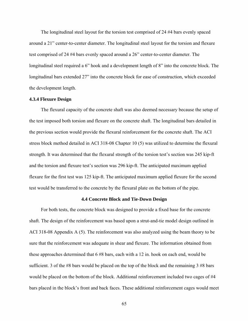
65
The longitudinal steel layout for the torsion test comprised of 24 #4 bars evenly spaced
around a 21” center-to-center diameter. The longitudinal steel layout for the torsion and flexure
test comprised of 24 #4 bars evenly spaced around a 26” center-to-center diameter. The
longitudinal steel required a 6” hook and a development length of 8” into the concrete block. The
longitudinal bars extended 27” into the concrete block for ease of construction, which exceeded
the development length.
4.3.4 Flexure Design
The flexural capacity of the concrete shaft was also deemed necessary because the setup of
the test imposed both torsion and flexure on the concrete shaft. The longitudinal bars detailed in
the previous section would provide the flexural reinforcement for the concrete shaft. The ACI
stress block method detailed in ACI 318-08 Chapter 10 (5) was utilized to determine the flexural
strength. It was determined that the flexural strength of the torsion test’s section was 245 kip-ft
and the torsion and flexure test’s section was 296 kip-ft. The anticipated maximum applied
flexure for the first test was 125 kip-ft. The anticipated maximum applied flexure for the second
test would be transferred to the concrete by the flexural plate on the bottom of the pipe.
4.4 Concrete Block and Tie-Down Design
For both tests, the concrete block was designed to provide a fixed base for the concrete
shaft. The design of the reinforcement was based upon a strut-and-tie model design outlined in
ACI 318-08 Appendix A (5). The reinforcement was also analyzed using the beam theory to be
sure that the reinforcement was adequate in shear and flexure. The information obtained from
these approaches determined that 6 #8 bars, each with a 12 in. hook on each end, would be
sufficient. 3 of the #8 bars would be placed on the top of the block and the remaining 3 #8 bars
would be placed on the bottom of the block. Additional reinforcement included two cages of #4
bars placed in the block’s front and back faces. These additional reinforcement cages would meet

66
the supplementary reinforcement requirements. Using this reinforcement arrangement, the
concrete block was determined to be a fixed base for the concrete shaft.
The tie-down was designed to be comprised of two channels connected by welded plates.
The channels individually and as a channel assembly were designed for flexure and local
buckling as specified in AISC 2005 (15). Each channel assembly’s resistance was required to not
exceed the floor capacity of 100 kips on either end, or 200 kips total. The bearing capacity of the
concrete at the point of contact between the channel assembly and the concrete block was also
checked to ensure that the loading from the channel would not cause the concrete to fail in that
region.
4.5 Instrumentation
To successfully obtain data from the experimental program, a plan for instrumentation
needed to be designed. The rotational stiffness of the concrete shaft was necessary to understand
the behavior of the newly designed concrete shaft. To obtain this information, a system of linear
variable displacement transducers (LVDTs) would need to be arranged.
To accurately determine the rotational stiffness of the concrete shaft, a system with 11
LVDTs was arranged. The arrangement of the LVDTs is detailed in Figure 4-12 through Figure
4-15. There will be one LVDT 6” from the point of applied force. There will be 4 LVDTs on the
base plate, 3 measuring vertical displacement, 1 measuring horizontal displacement (See Figure
4-12). The measurement from D4 (as seen in Figure 4-12) will measure the horizontal
displacement of the base plate. The rotation of the base plate was calculated using Equation 4-1.
+= −
gageDDD
R 311tan (4-1)
Where R = base plate rotation (rad) D1 = displacement of LVDT D1 (in.)

67
D3 = displacement of LVDT D3 (in.) Dgage = distance between LVDTs D1 and D3 (in.) Figure 4-13 shows the arrangement of the LVDTs on the top of the concrete shaft. Figure
4-14 shows the arrangement of the LVDTs on the bottom of the concrete shaft, where the
concrete shaft meets the block. The purpose of these LVDTs was to measure the rotation of the
concrete shaft relative to the base plate. Figure 4-15 shows the LVDT 6” from the load location.
4.6 Summary of Torsion Design
To summarize, the previous sections describe the design of the various components of both
experimental programs. For the torsion test, the key element of the design that dictated the rest of
the design was the concrete shaft. The concrete breakout or bearing strength of the shaft with the
embedded pipe and plate apparatus was the ultimate strength of the entire system. All other
components of the system were designed to preclude failure from these elements. This way the
experimental strength of the embedded pipe and plate system could be observed and appropriate
design guidelines could be written to detail the strength of the new system. Appendix A shows
detailed and dimensioned drawings of the testing apparatus. Appendix B shows detailed
calculations for the test apparatus.
The most critical components of the design were the embedded pipe and plate apparatus
and the reinforced concrete shaft. As long as the components of the concrete shaft and embedded
pipe and plate section exceeded that of the equivalent torsional concrete breakout strength then
the design was sufficient.
Table 4-1, shown below, summarizes the essential design components, their equivalent
torsional strengths, whether the strengths are mean or nominal, and their ratio compared to the
concrete breakout strength.

68
4.7 Summary of Torsion and Flexure Design
For the torsion and flexure test, once again the key element of the design that dictated the
rest of the design was the concrete shaft. The concrete breakout or bearing strength of the shaft
with the embedded pipe and plate apparatus in torsion and flexure was the ultimate strength of
the entire system. All other components of the system were designed to preclude failure from
these elements. Appendix A shows detailed and dimensioned drawings of the testing apparatus.
Appendix B shows detailed calculations for the test apparatus. Table 4-2, shown below,
summarizes the essential design components, their equivalent torsional and flexural strengths,
whether the strengths are mean or nominal, and their ratio compared to the interaction torsional
and flexural strength values.

69
Figure 4-1. Predicted concrete breakout failure
Figure 4-2. Schematic of torsion test specimen

70
Figure 4-3. Schematic of torsion and flexure test specimen
Figure 4-4. Front view of torsion test setup
Lever arm
Applied load
Channel tie-down
Concrete block with reinforcement
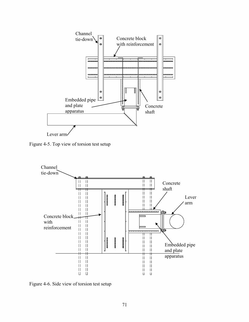
71
Figure 4-5. Top view of torsion test setup
Figure 4-6. Side view of torsion test setup
Channel tie-down
Lever arm
Concrete shaft
Embedded pipe and plate apparatus
Concrete block with reinforcement
Lever arm
Channel tie-down
Concrete shaft
Embedded pipe and plate apparatus
Concrete block with reinforcement

72
Figure 4-7. Views of the embedded torsion pipe section
Figure 4-8. Isometric view of embedded torsion and flexural pipe section for the second test
Embedded pipe
Welded plate
Welded annular plate
Bolt hole

73
Figure 4-9. Breakout overlap of the torsional and flexural breakouts
Figure 4-10. Interaction between torsion and flexure for concrete breakout
Overlapping breakout area
Torsional plate breakout area
Flexural plate breakout area

74
Figure 4-11. Fabricated pipe and plate apparatus
Figure 4-12. Arrangement of the LVDTs on base plate

75
Figure 4-13. Arrangement of the LVDTs on the top of the concrete shaft
Figure 4-14. Arrangement of the LVDTs on the bottom of the concrete shaft
Figure 4-15. Arrangement of the LVDTs at the load location

76
Table 4-1. Summary of pertinent design strengths for torsion test with 5500 psi concrete
Failure Mode Capacity Mean or
Nominal? Predicted
Load
Ratio of Failure
Capacities Embedded Pipe and Stiffeners Equivalent Torsion from Shear Parallel to an Edge 249 kip-ft Mean 27.67 1.00 Equivalent Torsion from Side Face Blowout 391 kip-ft Mean 43.44 1.57 Circular Shaft - 26" Torsion 373 kip-ft Nominal 41.44 1.50 Flexure 252 kip-ft Nominal 126.00 2.02 "Superstructure" Pipes - 16" x .5" Torsion 359 kip-ft Nominal 39.89 1.44 Flexure 392 kip-ft Nominal 196.00 3.14
Table 4-2. Summary of pertinent design strengths for torsion and flexure test with 5500 psi
concrete
Failure Mode Capacity Mean or
Nominal? Predicted
Load Ratio of Failure
Capacities Embedded Pipe and Stiffeners Equivalent Torsion from Shear Parallel to an Edge 348 kip-ft Mean 38.67 2.42 Equivalent Torsion from Side Face Blowout 523 kip-ft Mean 58.11 3.63 Equivalent Flexure from Shear Parallel to an Edge 218 kip-ft Mean 27.25 1.70 Equivalent Flexure from Side Face Blowout 337 kip-ft Mean 42.13 2.63 Anticipated Interaction Torsional Strength 144 kip-ft 16.00 1.00 Flexural Strength 128 kip-ft 16.00 1.00 Circular Shaft - 30" Torsion 253 kip-ft Nominal 28.11 1.76 Flexure 296 kip-ft Nominal 37.00 2.31 "Superstructure" Pipes - 16" x .5" Torsion 359 kip-ft Nominal 39.89 2.49 Flexure 392 kip-ft Nominal 49.00 3.06

77
CHAPTER 5 EXPERIMENTAL TEST RESULTS
Two separate tests were conducted on different specimens. The first test was conducted to
determine the viability of the alternative chosen in torsion only. This was determined by the
comparison of the experimental strength to an equivalent anchor bolt assembly’s calculated
strength (See Appendix A). The second test was conducted to determine the viability of the
alternative chosen in torsion and flexure and to determine the interaction of the torsion and
flexure failure modes. This also was determined by comparing the experimental strength of the
system to an equivalent anchor bolt assembly’s calculated strength (See Appendix A).
5.1 Torsion Test
5.1.1 Behavior of Specimen During Testing
The first test comprising of primarily torsional loading was conducted on September 23,
2009 at the Florida Department of Transportation Structures Research Center. The test specimen
was gradually loaded and the formation of cracks on the surface of the concrete was monitored.
At approximately 76.5 kip-ft, the bolts in the base connection slipped. This was because 1.5”
diameter bolts were used in 1.75” diameter bolt holes. Approximately 1/4” slip occurred. This
can be seen in Figure 5-1. At approximately 85.5 kip-ft, torsional cracks began to form on the
concrete shaft (See Figure 5-2). At approximately 153 kip-ft, concrete breakout failure cracks
began to form on the concrete shaft while the torsional cracks continued to widen (See Figure 5-
3). At approximately 191 kip-ft, the concrete breakout failure cracks began to widen noticeably
(See Figure 5-4). The foundation continued to be loaded until the specimen stopped taking on
more load. The torsion load peaked at approximately 250 kip-ft (See

78
Figure 5-5). At failure the foundation displayed the predicted breakout cone extending into
the foundation. As intended, the rest of the test specimen did not fail before the predicted
breakout failure occurred.
5.1.2 Summary of LVDT Test Results
Data was reduced to formulate an applied torsion versus plate rotation plot. The plot shows
that the embedded pipe and plate configuration ceased taking on additional load at 250 kip-ft
after the concrete breakout failure due to shear applied parallel to the edge resulting from the
applied torsion. The cylinder tests indicated that the compressive strength of concrete on the day
of testing was 5550 psi. When the predictions with the 28-day concrete strength were made, the
concrete breakout predicted 250 kip-ft and the side-face blowout method predicted 392 kip-ft.
The applied torsion versus plate rotation plot also shows a change in slope when the specimen
experienced a redistribution of load due to bolt slippage, formation of various cracks, and
widening of cracks. See Figure 5-6 for the graph of applied torsion versus plate rotation.
LVDT information was gathered at the front base plate, the face of the shaft, and the rear
of the shaft. As shown in Figure 5-7, the base plate rotated significantly more than the face of the
shaft. This can be attributed to the fact that bolt slippage occurred, resulting in approximately
1/4” additional rotation, which can contribute approximately 1.25° of additional rotation for the
base plate at failure. The rear of the shaft was designed to be a fixed support and proved to be so
until failure occurred and the entire shaft rotated.
5.1.3 Summary of Torsion Test
The alternative support structure proved effective at transferring torsional load during the
initial testing. It was determined that the modified anchor breakout equations accurately
predicted the behavior and strength of the failure within 0.16% error. The test specimen had a
cone shaped blowout failure within the foundation at the approximate location of the torsional

79
plates. It was also determined that the alternative tested had approximately twice the strength of
the calculated strength of an equivalent anchor bolt system (See Appendix B). For more details
on the calculated strength of an equivalent anchor bolt system compared to the test apparatus’
strength, see the test apparatus calculations in Appendix B.
5.2 Torsion and Flexure Test
5.2.1 Behavior of Specimen During Testing
The second test comprising of both flexural and torsional loading was conducted on
January 6, 2010 at the Florida Department of Transportation Structures Research Center. There
were concerns with bolt slippage due to both the flexural and torsional moment arm connections.
Prior to testing, the system was loaded with the crane only to remove some of the initial rotation
due to bolt slippage (See
Figure 5-8). During testing, the test specimen was loaded at approximately 100 pounds
force per second and the formation of cracks on the surface of the concrete was monitored. At
approximately 10.8 kips, bond between the concrete and the embedded pipe loosened, causing a
change in stiffness. At approximately 14.3 kips, flexural and torsional cracks began to form on
the concrete shaft (See Figure 5-9). At approximately 20.2 kips, concrete breakout failure cracks
began to form on the concrete shaft while the torsional cracks continued to widen (See Figure 5-
10). At approximately 24.5 kips, the concrete breakout failure cracks began to widen noticeably
(See Figure 5-11). The foundation continued to be loaded until the specimen stopped taking on
additional load. The applied load peaked at approximately 26.3 kips. At failure the foundation
displayed the predicted breakout cone indicated by bulging concrete deep within the foundation.
As intended, the rest of the test specimen did not fail before the predicted breakout failure
occurred. Note that an applied load of 1 kip produces a flexural moment of 8 kip-ft and a
torsional moment of 9 kip-ft.

80
The formation of the initial cracks was noteworthy because it indicated a change in the
concrete behavior from a concrete pedestal with anchor bolts and confining reinforcement.
Rather than the 45 degree torsional cracks forming at the surface of the concrete closest to the
base plate, cracks parallel to the embedded pipe formed at the surface closest to the base plate.
These parallel cracks extended several inches down the foundation and then began to exhibit
typical torsional 45 degree crack formation. This cracking behavior shows that the torsional load
is being transferred from the steel to the concrete deeper in the foundation. This will be
beneficial because the frequent construction mistake of placing the rebar cage too deep in the
foundation often leaves the surface of the concrete under reinforced. If the load will be
transferred into the concrete deeper in the foundation, the problem of the under reinforced
surface concrete will be partially negated.
5.2.2 Summary of LVDT Test Results
Data was reduced to formulate an applied load versus rotation plot for both flexure and
torsion. The plots show that the embedded pipe and plate configuration ceased taking on
additional load after 26.3 kips after the concrete breakout failure from flexure resulting from the
applied bending moment. The cylinder tests indicated that the compressive strength of concrete
on the day of testing was 5180 psi. When the predictions with the 28 day concrete strength were
made, the flexural concrete breakout was predicted to be 26.4 kips and the torsional concrete
breakout was predicted to be 37.5 kips. When the predictions with the 28 day concrete strength
were made, the flexural side-face blowout strength was predicted to be 40.9 kips and the
torsional side-face blowout strength was predicted to be 56.4 kips. The applied load versus
torsional plate rotation plot also shows a change in slope when the specimen experienced a
redistribution of load due to bolt slippage, bond changes, formation of various cracks, and

81
widening of cracks. See Figure 5-12 for the graph of applied load versus torsional plate rotation.
See
Figure 5-13 for the graph of the applied load versus flexural rotation.
The graph of load versus torsional rotation for the second test was created from data
gathered from LVDT’s place on the base plate of the embedded pipe. The graph showing the
torsional rotation of the base plate for this test (Figure 5-12) shows significantly less rotation
than the plate of the previous test (Figure 5-6). This can be attributed to the fact that the LVDT
was placed on the base plate attached to the moment arm on the previous test and the LVDT was
placed on the base plate attached to the embedded pipe on this test. The moment arm base plate
would feel more rotation because of the bolt slippage occurring at the connection.
The graph of load versus flexural rotation was gathered from the LVDT’s placed on the
bottom of the base plate, front of shaft, and rear of shaft. The graph shows that the rotation
between the face of the shaft and the base plate was significantly greater than the rotation
between the face of the shaft and the rear of the shaft. This can be attributed to several things,
including the steel pipe and base connection was less stiff than the concrete pedestal as well as
the concrete block was adequately designed as a fixed support, which would have restrained the
rotation at the base and created a deflection that could be adequately described by an applied
moment on a fixed cantilever.
As stated earlier, the LVDT’s gathered information from the base plate, the front of the
concrete pedestal and the rear of the concrete pedestal. The base plate’s torsional rotation
exceeded the rotations from the front of the concrete pedestal and the back of the concrete
pedestal (See

82
Figure 5-14). This shows that the steel pipe and base plate was less stiff than the concrete
pedestal. The lack of considerable rotation in the rear of the concrete pedestal once again shows
that the concrete block connected to the concrete pedestal was adequately designed as a fixed
support.
5.2.3 Summary of Torsion and Flexure Test
Overall, this test proved the embedded pipe and plates section was successful at
transferring load from the superstructure to the substructure. It was determined that the modified
anchor breakout equations for flexure also accurately predicted the behavior and strength of the
failure. The predicted failure load for the concrete breakout in flexure was 26.4 kips and the
applied failure load was 26.3 kips, with the largest breakout occurring on the bottom of the test
specimen, indicating a flexure failure. The test specimen had a breakout failure deep within the
foundation at the approximate location of the flexural plate. It was also determined that the
alternative tested had approximately twice the strength of the calculated strength of an equivalent
12 anchor bolt system. For more details on the calculated strength of an equivalent anchor bolt
system compared to the test apparatus’ strength, see the test apparatus calculations in Appendix
B.

83
Figure 5-1. Lines drawn on base plate to show bolt slippage
Figure 5-2. Formation of torsional cracks

84
Figure 5-3. Formation of concrete breakout failure cracks
Figure 5-4. Concrete breakout failure cracks widen

85
Figure 5-5. Specimen at failure
Figure 5-6. Torsional moment and rotation plot for base plate of torsion test
Predicted Maximum
Failure Cracks Widen
Failure Cracks Form
Torsion Cracks Form
Bolt Slippage Ends

86
Figure 5-7. Torsional moment and rotation plot for torsion test
Figure 5-8. Test specimen prior to testing
Rear of Shaft
Face of Shaft
Outer Base Plate

87
Figure 5-9. Torsional and flexural cracks forming
Figure 5-10. Formation of concrete breakout failure cracks in second test

88
Figure 5-11. Widening of concrete breakout failure cracks in second test
Figure 5-12. Load and torsional rotation of base plate for torsion and flexure test
Bond loosens
Torsion and flexure cracks form
Failure cracks widen
Predicted failure
Failure cracks form

89
Figure 5-13. Load and flexural rotation for the second test
Figure 5-14. Load and torsional rotation for test specimen for the second test
Base plate to rear of
shaft
Predicted failure
Failure cracks widen
Base plate to face of
shaft
Face of shaft
Bond loosens
Bolt slippage ends
Base plate
Rear of shaft
Face of shaft to rear
of shaft

90
CHAPTER 6 SUMMARY, CONCLUSIONS, AND RECOMMENDATIONS
The purpose of this research program was to determine a suitable alternative support
structure for cantilever sign/signal structures and test the selected alternative to verify its
viability. After a review of the problems with the current anchor bolt design and research into
alternatives found in other fields, an embedded pipe and plate configuration was selected for
testing. In order to quantify the strength of the embedded pipe and plate configuration, a review
of current ACI 318 formulas relating to anchorage to concrete was conducted. The applicable
equations regarding anchor breakout due to shear applied parallel to an edge as well as side-face
blowout due to an anchor in tension were modified to accommodate the differences in geometry
and behavior of an anchor and the embedded pipe and plate system. Once the predicted strength
in torsion and flexure was quantified, testing was conducted on two different specimens. The
purpose of the first experiment was to test primarily torsion, and the second experiment tested
both torsion and flexure. The first test proved that the alternative selected was a viable alternative
to transfer torsional load from the monopole to the foundation.
6.1 Implications of Test Results
6.1.1 Torsion Test
The implication of the torsion test is that the alternative selected is a viable alternative for
transferring torsion from the monopole to the foundation. A comparison of the torsion test results
and the calculated strength of an equivalent anchor bolt system in torsion show that the
embedded pipe and plate configuration has double the strength of the equivalent anchor bolt
system (See design calculations in Appendix B). The predicted breakout pattern of a failure cone
within the foundation at the approximate location of the torsion plates was exhibited during
testing, signifying that the predicted behavior was likely correct. The modified concrete breakout

91
equations for torsion (See Equations 3-5 and 3-6) were proven accurate as the predicted failure
load with these equations was less than 1% disparate from the tested failure load.
The results imply that the embedded pipe and plate configuration in torsion alone would be
an adequate alternative to the current anchor bolt system. The torsional strength of the alternative
is greater than the anchor bolt system and can be accurately predicted using the modified
concrete breakout equations for torsion.
6.1.2 Torsion and Flexure Test
The implication of the torsion and flexure test is that the alternative selected, the embedded
pipe with torsion and flexure plates, is a suitable alternative to the current design using anchor
bolts. A comparison of the experimental test values and the calculated equivalent strength of an
anchor bolt setup show that the experimental test strength in flexure is approximately twice that
of the equivalent anchor bolt system (See design calculations in Appendix B). A large bulge of
concrete on the bottom of the shaft signifies a concrete breakout of the embedded flexure plate,
verifying the breakout was the failure mode. The modified concrete breakout equations for
flexure (See Equations 3-8 and 3-9) were proven accurate as the predicted failure load with these
equations was less than 1% off from the tested failure load.
These results imply that the tested system with the embedded pipe and torsion and flexure
plates is a viable alternative to the current anchor bolt system. The failure can be predicted
accurately using both the torsion and flexure plates and can easily be quantified using the
modified concrete breakout equations.
6.2 Recommendations for Future Testing
6.2.1 Introduction and Background
Cantilever sign/signal structures typically have a single monopole supported by a cast-in-
place foundation. As was mentioned in Chapter 2, the most common method of connecting the

92
monopole to the foundation is through the use of anchor bolts attached to an annular plate
welded to the monopole (See Figure 6-1). Although this connection is the most widely used,
many studies in the past few years have reported that fatigue of the annular plate and anchor bolt
configuration is a significant concern.
In the early 1990’s it became evident that the Supports Specifications were not providing
enough guidance on designing for vibration and fatigue. In response to the large problems with
vibration and fatigue in cantilever signal/sign support structures, the National Cooperative
Highway Research Program (NCHRP) initiated project 10-38 in 1993 (6). The information
obtained from project 10-38 was published as NCHRP Report 412. The recommendations
provided in NCHRP Report 412 were incorporated into the design provisions in the 2001
Supports Specifications.
NCHRP Report 412 found that galloping, vortex shedding, natural wind gusts, and truck-
induced wind gusts were the primary wind-loading mechanisms that were responsible for most
vibration and fatigue-related stresses on cantilever structures (7). Based on this information,
importance factors were assigned for each of the four wind-loading mechanisms on three fatigue
categories. Report 412 describes, “Structures classified as Category I would present a high
hazard in the event of failure and should be designed to resist rarely occurring wind loading and
vibration phenomena” (7).
The fatigue design approach recommended by NCHRP Report 412, and adopted by the
2001 Supports Specifications, was to design cantilever support structures to resist specified static
wind loads, modified by the importance factors (3). The stresses obtained from the modified
static wind loads would be designed to satisfy the requirements of their recommended detail
categories for an infinite life fatigue design (3).

93
Due to the lack of proper guidance on vibration and fatigue design in the Supports
Specifications until the 2001 edition, many of the supports structures designed prior to the 2001
edition are now experiencing fatigue problems, particularly on the welded annular base plate and
anchor bolt connection (3).
Despite the fact that NCHRP Report 412 finally gave guidance to designers on fatigue
design for cantilever signal/sign support structures, the rate of fatigue cracking and failure has
continued and may have even increased (6). Because of this, NCHRP Project 10-38(2) was
initiated to further address fatigue-resistant design of the cantilever support structures. The
information obtained from Project 10-38(2) was published as NCHRP Report 469. NCHRP
Report 469 partially attributes the continued fatigue problems with the increasing use of longer
horizontal spans of the cantilever sign/signal structures (6). Past inspections have shown that the
following typical and special problems on cantilever signal/sign structures are prevalent (16):
• Cracked anchor bolts both above and within the concrete • Loose nuts and missing connectors, both on anchor bolts and structural bolts • Cracked and broken welds • Split tubes • Plugged drain holes, debris accumulation and corrosion • Internal corrosion of tubular members • Poor fit-up of flanged connections with cracking and missing bolts • Structure overload due to installation of signs exceeding design square footage
Some of the recommended revisions proposed in NCHRP Report 469 to the 2001 Supports
Specifications fatigue design and partially incorporated into the 2006 Interim to Standard
Specifications for Structural Supports for Highway Signs, Luminaires, and Traffic Signals
include the following (6; 17):
• Clearly define criteria for categorizing the structure fatigue categories
• Galloping mitigation devices (sign blanks or other proved mitigation devices) not be used to remove the galloping design load entirely, but would instead alter the fatigue category from Category I to Category II

94
• The equivalent static pressure range be changed from 1760CD to 900CD for truck-induced wind gusts
• A statement be included in the vortex-shedding section, similar to that in the galloping section of the 2001 Supports Specifications, allowing for mitigation of vibration due to vortex shedding after a problem with vibration in double-curvature has been observed
• Minor changes to the design some of the fatigue-resistant details, with the inclusion of an additional fatigue-resistant detail to be considered
The problems identified with the fatigue of the steel annular base plate and the concrete
breakout from the anchor bolts necessitates looking at alternatives to the current anchor bolt and
base plate connection. The following are some options to explore regarding alternative
connections that do not use the same anchor bolt and annular base plate connection.
6.2.2 Tapered Embedded Steel Pipe and Plate Option with Bolted Slip Base Connection
In this option, a tapered welded pipe and plate configuration will be embedded into the
foundation with a portion of the pipe projecting from the foundation. The monopole will be
placed over the projecting pipe, acting as a sleeve, and secured into place by several bolts that
will extend through the diameter of the pole. See Figure 6-2 for a sketch of this connection.
The primary benefit associated with this connection is that the annular plate and anchor
bolts have been removed, thus eliminating the questionable connecting elements of the design.
The design calculations for the bolted connection would be relatively easy. The bolts would need
to be designed for shear strength and the bearing strength of the bolt holes would also be a
primary consideration. The embedded pipe and plate section has been tested to determine its
torsional and flexural viability. Since the embedded pipe and plate alternative has been proven
effective at transferring load, this connection would seem a likely candidate for consideration.
However, one of the drawbacks to this design is the construction feasibility. A typical
monopole’s taper is 0.14 in/ft. In order to provide the shorter embedded tapered section, an
additional pole would need to be ordered and cut to the appropriate length at the appropriate

95
point on the pole. This process may prove tedious and time consuming. The connecting bolts
bearing on the monopole may require an increase in pipe thickness for the monopole which
could lead to additional expense. Additionally, this option would include corrosion as a potential
problem since the entire connection is steel.
Alignment of this connection may be difficult to accomplish during construction. One
method possible to control the alignment would be to place the sleeve flush with the top of the
concrete foundation. However, if a standoff was required, there might be difficulty leveling the
monopole for placement. The bolt holes will ensure the final product will be level because they
need to be aligned properly to ensure the bolts will fit through the holes. If a bolt is forced into
place because of improper alignment it may incur additional stress.
Design strength considerations for this connection include, but are not limited to, the
following:
• Bolt shear strength • Bolt bearing strength (on steel pipes) • Fatigue (of bolts) • Breakout strength (of embedded section on concrete foundation) • Torsional strength • Flexural strength
This option provides a suitable alternative to the current annular plate and anchor bolt
connection. The FDOT currently uses a detail similar to this in Index No. 11860, Single Column
Ground Signs, in their Design Standards (18). See Figure 6-3 for a sketch of the FDOT detail.
However, this detail has been specified for use with aluminum single column posts for ground
signs and not for steel monopoles.
6.2.3 Embedded Steel Pipe and Plate Option with Grouted Slip Base Connection
In this option, a standard welded pipe and plate configuration will be embedded into the
foundation with a portion of the pipe projecting from the foundation. The monopole will be

96
placed over the projecting pipe, acting as a sleeve, and secured into place by several bolts that
will extend through the diameter of the pole. The gap between the tapered monopole and the
embedded pipe’s projection will be filled with high-strength grout. See Figure 6-4 for a sketch of
this connection.
As with the tapered embedded steel pipe and plate option, the primary benefit associated
with this connection is that the annular plate and anchor bolts have been removed. The design
calculations for the bolted connection would be relatively easy. The bolts would need to be
designed for shear strength and the bearing strength of the bolt holes would also be a primary
consideration. A benefit of this design over the tapered steel pipe design would be that the
embedded steel pipe would be more easily obtained.
One of the drawbacks to this design is the added complication of high-strength grout.
Grout was found to be improperly placed in the current anchor bolt and base plate connection
and has the potential to be improperly placed in this connection. Another potential drawback is
that the connecting bolts bearing on the monopole may require an increase in pipe thickness for
the monopole which could lead to additional expense. Additionally, this option would include
corrosion as a potential problem since the entire connection is steel.
Alignment of this option during construction may prove difficult because of the small
tolerance for error on aligning the bolt holes. Allowing the monopole to be placed directly on the
concrete foundation will reduce some error.
Design strength considerations for this connection include, but are not limited to, the
following:
• Bolt shear strength • Bolt bearing strength (on steel pipes) • Fatigue (of bolts) • Breakout strength (of embedded section on concrete foundation)

97
• Torsional strength • Flexural strength
This option provides a possible alternative to the current annular plate and anchor bolt
connection. The FDOT currently uses a detail similar to this in Index No. 11860 in their Design
Standards (See Figure 6-3). However, this detail has only been used with aluminum single
column posts for ground signs.
6.2.4 Embedded Concrete Pipe with Bolts Option with Bolted Slip Base Connection
In this option, a prestressed concrete pipe with bolts option, either tapered or not tapered,
will be embedded into the foundation with a portion of the pipe extending beyond the
foundation. This option is very similar to the embedded steel pipe and plate option with slip base
connection. One obvious difference would be that the embedded pipe would be concrete rather
than steel. Another difference is that the embedded portion would have bolts acting in a manner
similar to the plates. The bolts would connect plates to the concrete section. As explained later in
this section, the embedded concrete pipe with bolts may be replaced with a geometric section
without bolts if necessary. See Figure 6-5 for the overall setup of this connection as a concrete
pipe with bolts.
One immediate benefit associated with this configuration is that the annular plate and
anchor bolt connection has been removed. Another benefit over the embedded steel pipe and
plate option is that this embedded concrete option removes corrosion of the embedded pipe as a
potential problem. As with the previous option, the bolted connection bearing on the monopole
may require an increase in thickness for the monopole, leading to additional expense.
A potentially difficult piece to construct would be the embedded concrete pipe with bolts.
One option would be to order spun concrete poles from a manufacturer. The poles would include
prestressed strands as well as spiral reinforcement and would be light and durable. The through

98
bolt holes would be included by using a cast-in-place PVC pipe during fabrication. Another
option would be to use a geometric section without bolts instead of the round section with bolts.
The geometric section would provide the required torsional resistance once embedded in the
foundation that the bolts are providing in the round section.
Design strength considerations for this connection include, but are not limited to, the
following:
• Bolt shear strength • Bolt bearing strength (on steel monopole) • Bolt bearing strength (on embedded concrete section) • Fatigue (of bolts) • Breakout strength (of embedded section on concrete foundation) • Torsional strength • Flexural strength
As with the previous option, the embedded steel pipe and plate option, this configuration
may provide a suitable alternative to the current annular base plate and anchor bolt connection.
As mentioned before, the FDOT currently uses a detail similar to this in Index No. 11860 in their
Design Standards. Given that, the detail in the Design Standards has only been specified for use
with aluminum single column posts for ground signs.
6.2.5 Cast-in-Place Solid Concrete Pedestal with Bolted Slip Base Connection
In this option, a cast-in-place solid concrete pedestal would be poured projecting from the
foundation with the tapered steel monopole placed over the pedestal projection and the two
connected with bolts. Some longitudinal rebar would connect the solid concrete pedestal
projection to the foundation. See Figure 6-6 for the setup of this connection.
As with the previous option, one benefit to this connection would be that the annular base
plate and anchor bolt connection would be eliminated. Another benefit to this connection is that
the construction would be relatively easy because it’s all cast-in-place. One problem with this
99
connection is that the connection may have less flexural strength because the rebar would be the
only flexural reinforcement. And as with the other bolted slip connections, the bolt bearing may
require an increase in monopole member thickness.
Design strength considerations for this connection include, but are not limited to, the
following:
• Bolt shear strength • Bolt bearing strength (on steel monopole) • Bolt bearing strength (on cast-in-place solid concrete pedestal) • Fatigue (of bolts) • Torsional strength • Flexural strength
6.2.6 Embedded Concrete Pipe with Bolts Option with Grouted Splice to Concrete Monopole
In this option, a prestressed concrete pipe with bolted plates would be embedded into a
concrete foundation. The bolts and plates would resist torsion by bearing on the surrounding
concrete foundation. The splice would be similar to that presented in FDOT Project BC354-80
Final Report, Volume 2 (19). See Figure 6-7 for the setup of this connection. The splice
connection would be a steel HSS pipe with welded rebar hoops placed in the hollow core of the
prestressed spun concrete pipe and then pressure grouted into place.
This option has several advantages over the current annular plate and anchor bolt
connection. The primary advantage is that the connection does not use annular plates or anchor
bolts and will eliminate the fatigue problems associated with the current connection option.
Another advantage is that since the steel portion of the connection is grouted in the core of the
spun concrete poles, the steel will not suffer as much corrosion unless one of the grout inlet holes
is compromised.

100
This option does have some disadvantages as well. The construction will be more tedious
and time consuming than the current connection option. This connection can be more costly than
the current connection option because of the increase in number of elements as well as the cost
of each element. The inclusion of grout adds an additional complication for design and
construction error. The viability of a concrete monopole for cantilever use is also questionable.
The horizontal member that needs to be attached for sign/signal purposes may be too large to
attach to the concrete monopole. This connection may be more difficult to monitor and repair
than a visible connection.
Design strength considerations for this connection include, but are not limited to, the
following:
• Breakout strength (of embedded section on concrete foundation) • Grout strength • Torsional strength • Flexural strength • Monopole to horizontal member connection
6.2.7 Embedded Steel Pipe and Hoops with Grouted Slip Base Connection
This option entails using a steel pipe and hoops embedded into the foundation and stubbing
out from the foundation. The steel pipe and hoops would then be covered by a concrete
monopole and pressure grouted into place. See Figure 6-8 for this connection configuration.
The primary benefit of this connection is that it removes the fatigue-prone elements of the
current anchor bolt and annular base plate connection. It offers good torsional and flexural
resistance with the embedded pipe and hoop section. The pipe and hoop section may be
expensive to fabricate. The pressure grouting has the potential to be a problem during
construction as it has been a problem in the past. As mentioned earlier, the concrete monopole

101
may not be viable to connect to the steel horizontal member. This connection may also be more
difficult to monitor or repair than a visible connection.
Design strength considerations for this connection include, but are not limited to, the
following:
• Breakout strength (of embedded section on concrete foundation) • Grout strength • Torsional strength • Flexural strength • Monopole to horizontal member connection
6.2.8 Embedded Steel Pipe and Plates with Bolted Plate Connection
In this option, an annular plate would be welded to both the monopole and the stub of the
embedded steel pipe protruding from the foundation. The two annular plates would be bolted
together, allowing for space between for leveling nuts to be used. The leveling nuts would make
it easier to ensure the monopole was erected properly. See Figure 6-9 for the connection setup.
One benefit with this connection is that it would be easy to construct and the materials
would be easy to obtain. Since this option is very similar to the current base plate and anchor bolt
option, it would not be difficult for designers to transition to this design. This option also
provides the benefit that the embedded pipe would not need to be tapered and therefore could be
more easily constructed by using a standard circular HSS section.
However, one major drawback to this design is that it has the potential to have fatigue
problems similar to the current base plate and anchor bolt design. The welds, bolts, and plates
could experience fatigue cracking after the cyclical wind stresses are imposed on the connection.
Corrosion would also remain an issue with this connection. This connection does not necessarily
fix the problem with fatigue associated with the current annular plate and anchor bolt design, but
it does offer another alternative.

102
Design considerations for this connection include, but are not limited to the following:
• Bolt shear strength • Bolt bearing strength (on annular plates) • Flexural strength (of annular plates and bolts) • Weld strength • Axial strength (of annular plates and bolts) • Fatigue (of bolts, welds, and annular plates)
As demonstrated by the increase in the number of design considerations, this option has
more possibilities for failure. It does include welds, annular base plates, and bolts as the current
base plate and anchor bolt option does. Therefore, this option does not eliminate the problems
associated with the current base plate and anchor bolt design, other than removing anchor bolts
as a potential failure and replacing it with a standard bolted connection.
6.2.9 Embedded Steel Pipe and Plates with Welded Sleeve Connection
In this connection, a steel pipe and plate configuration would be embedded in the concrete
foundation and connected to the steel monopole by a welded sleeve. The sleeve would consist of
a high strength steel pipe section fillet welded to the monopole and embedded steel pipe and
plates around the perimeter of the pipes. See Figure 6-10 for the connection detail.
One benefit of this connection is that it would be relatively easy to construct and the
materials would be easy to obtain. This connection does not use bolts and thus removes bolt
fatigue as a problem. The annular plate is also removed, also eliminating fatigue problems with
this component of a connection.
However, the fillet welds are susceptible to fatigue cracking similar to the current base
plate and anchor bolt section. Corrosion would also remain an issue because the connection is
comprised totally of steel. The welded sleeve’s pipe thickness would need to be large to handle
the large flexural and torsional moments presented at the connection. This connection may make
it difficult to align the monopole correctly during construction.
103
Design considerations for this connection include, but are not limited to the following:
• Weld strength • Fatigue (of welds) • Flexural strength • Torsional strength • Breakout strength (of embedded section on concrete foundation)
This option provides a solution to part of the fatigue problems associated with the annular
plates, bolts, and welds. The welds will remain a fatigue problem. While this option may not
solve all of the problems, it does provide a solution that may be relatively easy to construct.
6.2.10 Summary of Recommendations for Future Testing
Future testing of alternative connections to resolve the fatigue and vibration problems
exhibited in the current base plate and anchor bolt connection is highly recommended. The
embedded pipe and plates configuration has been proven to be effective at transferring torsion
and flexure and therefore a connection incorporating the embedded pipe and plates would be
ideal. The option that may have the greatest potential that incorporates the embedded pipe and
plates option is the grouted slip base connection. The benefits of this connection are that it
includes the embedded pipe and plates, the design would be relatively simple, the anchor bolts
are removed, and the fatigue prone welds that present a problem are eliminated.
6.3 Summary
The alternative selected, the embedded pipe and plate configuration, has worked in
transferring torsional and flexural load from the monopole to the foundation during experimental
testing. The controlling failure behavior of the system is characterized by a concrete breakout in
the shape of a cone in the vicinity of the embedded plates. The strength of the failure modes can
be quantified by using modified ACI 318 equations. The embedded pipe and plate configuration
also has potential to work in an alternative base connection that is recommended for future

104
testing. The proper use of the findings in this testing program will allow for future prevention of
the types of failures exhibited in the 2004 hurricane season.

105
Figure 6-1. Typical sign/signal base connection
Figure 6-2. Embedded steel pipe and plate option with slip base connection
Bolt
Tapered embedded steel pipe and plates
Concrete foundation
Tapered steel monopole “sleeve”
Welded base plate
Anchor bolt
Monopole
Concrete foundation

106
Figure 6-3. FDOT Design Standards Index No. 11860(18)
Figure 6-4. Embedded steel pipe and plate option with grouted slip base connection
Tapered steel monopole
Bolt
Embedded steel pipe and plates
Concrete foundation
Grout
Seal
Aluminum column
Sleeve bolt Aluminum
sleeve
Aluminum
Concrete foundation
Aluminum base plates
High strength base bolt

107
Figure 6-5. Embedded concrete pipe and plate option with slip base connection
Figure 6-6. Cast-in-Place solid concrete pedestal with slip base connection
Concrete foundation
Longitudinal rebar
Cast-in-Place solid concrete pedestal
Tapered steel monopole “sleeve” Bolt
Tapered steel monopole “sleeve”
Bolt Embedded concrete pipe with bolts
Concrete foundation Steel
plate

108
Figure 6-7. Embedded concrete pipe with bolts option with grouted splice to concrete monopole
Figure 6-8. Embedded steel pipe and hoops with grouted slip base connection
Concrete foundation
Tapered concrete monopole “sleeve”
Steel HSS pipe with welded rebar hoops and plates Grout
Grout seal
Embedded concrete pipe with bolts
Concrete foundation
Steel plate
Tapered concrete monopole
Steel HSS pipe with welded rebar hoops
Grout l
Grout
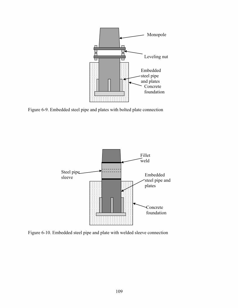
109
Figure 6-9. Embedded steel pipe and plates with bolted plate connection
Figure 6-10. Embedded steel pipe and plate with welded sleeve connection
Embedded steel pipe and plates
Concrete foundation
Steel pipe sleeve
Fillet weld
Monopole
Leveling nut
Embedded steel pipe and plates
Concrete foundation

110
APPENDIX A TEST APPARATUS DRAWINGS
Figure A-1. Dimensioned front elevation drawing of torsion test apparatus

111
Figure A-2. Dimensioned plan view drawing of torsion test apparatus

112
Figure A-3. Dimensioned side elevation drawing of torsion test apparatus

113
Figure A-4. Dimensioned view of channel tie-down for torsion test apparatus

114
Figure A-5. Dimensioned drawings of embedded pipe and plate for torsion test

115
Figure A-6. Dimensioned front elevation drawing of torsion and flexure test apparatus

116
Figure A-7. Dimensioned plan drawing of torsion and flexure test apparatus
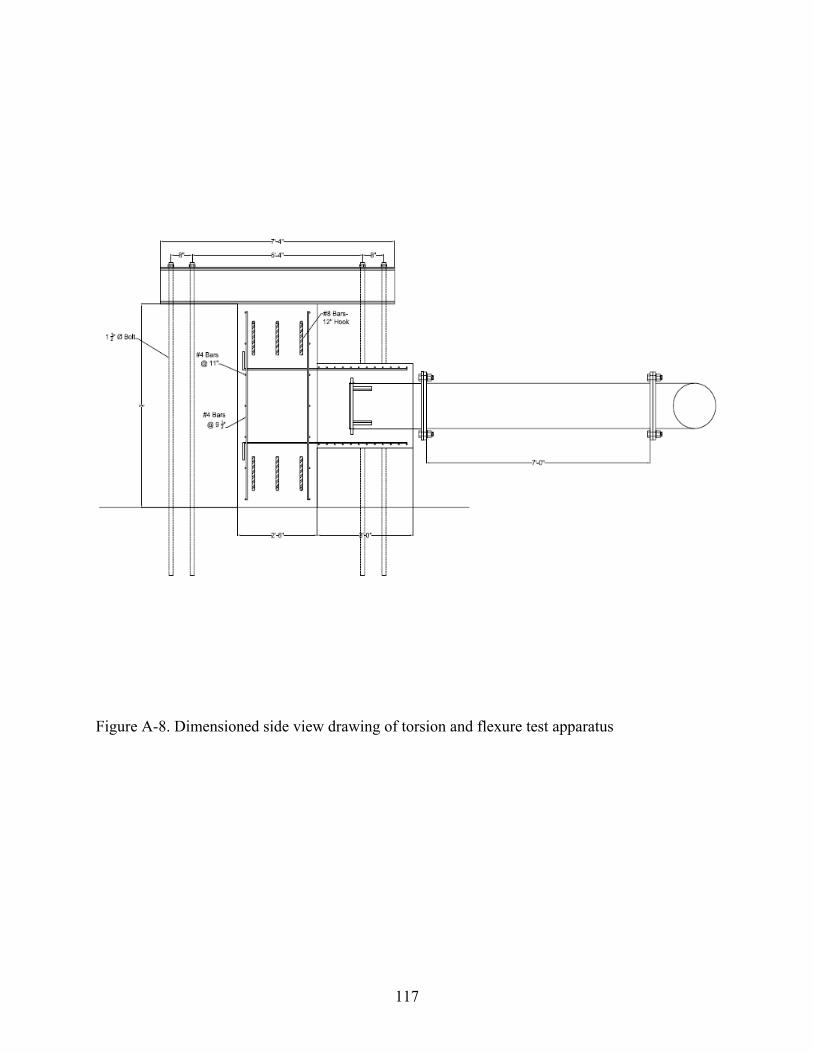
117
Figure A-8. Dimensioned side view drawing of torsion and flexure test apparatus

118
Figure A-9. Dimensioned drawing of channel tie-down for torsion and flexure test

119
Figure A-10. Dimensioned drawing of flexure extension pipe for torsion and flexure test

120
Figure A-11. Dimensioned view of embedded pipe and plates for torsion and flexure test

APPENDIX BDESIGN CALCULATIONS
Torsion Design Calculations
Input and Properties
Shaft
Diameter of the Shaft ds 26in
Concrete Strength fc 5500psi
Lenth of Shaft Ls 36in
Hoop Steel
Hoop Steel Area Ahoop .2in2
Hoop Steel Diameter dhoop .5in
Spacing of Hoop Steel shoop 2in
Yield Strength of Hoop Steel fy_hoop 60ksi
Centerline of Hoop Steel Diamter dh 22in
Longitudinal SteelAlong .2in
2Longitudinal Steel Area
dlong .5inLongitudinal Steel Diameterfy_long 60ksiYield Strength of Longitudinal Steelnlong 24Number of Long Steel Bars
Stiffener Plates
Thickness of the plate t 1in
Width of the plate b 1in
Length of plate L 7in
Yield strength of the plate fy_plate 50ksi
Embedded Pipe
Thickness of the pipe tpipe .25in
Diameter of the pipe dpipe 16in
Fy_pipe 42ksi
Fu_pipe 58ksi
Moment Arm Moment_Arm 9ft
Input and Properties
121

STIFFENER DESIGNCalculation of Capacity with Anchor Bolts
Input
Shaft
Diameter of the Shaft ds 26 in
Concrete Strength fc 5.5 ksi
Equivalent Anchor Bolt
Diameter of the bolt do 1.5in
Center-to-center diameter of bolts db 20in
Number of bolts No_Bolts_equiv 12
Yield strength of bolts fy_bolt_equiv 105ksi
Concrete Breakout Equivalent Torsional Strength
Based on ACI 318 Appendix D - Design requirements for shear loading
coverds db
2
cover 3 in
ca1
db
2
2
3.25ds
2
2db
2
2
db
2
3.25
ca1 2.46 in
A360deg
No_Bolts_equiv
A 30 deg
chord_group 2ds
2 sin
A
2
chord_group 6.73 in
Amin_group 2 asin3.0 ca1
ds
Amin_group 33.03 deg
Check_Group_Effect "Group Effect" A Amin_groupif
"No Group Effect" otherwise
Check_Group_Effect "Group Effect"
AVc No_Bolts_equiv chord_group 1.5 ca1AVc 298.42 in
2
AVco 4.5 ca12
AVco 27.31 in
2
le 8 dole 12 in
Vb 13le
do
.2
do
in
fc
psi
ca1
in
1.5
lbfVb 6.92 kip
122

ψcV 1.4
ψecV 1.0
ψedV 1.0
Vcbg No_Bolts_equiv ψedV ψcV Vb Check_Group_Effect "No Group Effect"=if
AVc
AVco
ψecV ψedV Vb
Check_Group_Effect "Group Effect"=if
Vcbg 75.62 kip
Vcbg_parallel 2 VcbgVcbg_parallel 151.23 kip
Tn_breakout_ACI Vcbg_parallel
db
2
Tn_breakout_ACI 126.03 ft·kip
Calculation of Capacity with Anchor Bolts
Calculation of Capacity with Stiffener Plates
Input
Width of the stiffener plates b 1 in
Thickness of the stiffener plates t 1 in
Length of the stiffener plates L 7 in
Length of the shaft Ls 36 in
Diameter of upright/embedded pipe dpipe 16 in
Diameter of stiffeners dst dpipe
Number of stiffeners No_Stiff 4
123
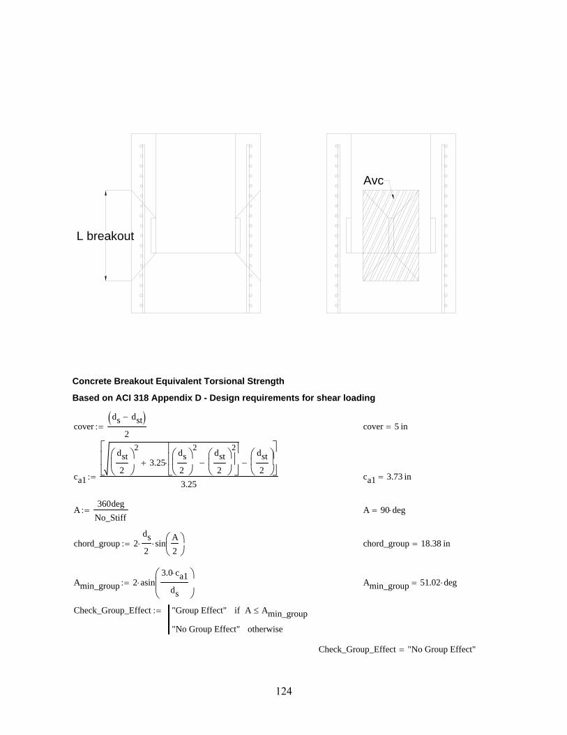
L breakout
Avc
Concrete Breakout Equivalent Torsional Strength
Based on ACI 318 Appendix D - Design requirements for shear loading
coverds dst
2 cover 5 in
ca1
dst
2
2
3.25ds
2
2dst
2
2
dst
2
3.25 ca1 3.73 in
A360deg
No_Stiff A 90 deg
chord_group 2ds
2 sin
A
2
chord_group 18.38 in
Amin_group 2 asin3.0 ca1
ds
Amin_group 51.02 deg
Check_Group_Effect "Group Effect" A Amin_groupif
"No Group Effect" otherwise
Check_Group_Effect "No Group Effect"
124

lbreakout L 2 1.5ca1 lbreakout 18.2 in
AVcp min lbreakout Ls 3 ca1 AVcp 203.77 in2
AVco 4.5 ca12
AVco 62.69 in2
le L le 7 in
Vb 13le
b
.2
b
in
fc
psi
ca1
in
1.5
lbf Vb 10.26 kip
Vcbp
AVcp
AVco
ψecV ψedV ψcV No_Stiff Vb Vcbp 186.75 kip
Vcbp_parallel 2 Vcbp Vcbp_parallel 373.5 kip
Tn_breakout_plate Vcbp_parallel
dst
2
Tn_breakout_plate 249 ft·kip
Calculation of Capacity with Stiffener Plates
Calculation of Capacity with Side-Face Blowout
Input
Width of the stiffener plates b 1 in
Thickness of the stiffener plates t 1 in
Length of the stiffener plates L 7 in
Length of the shaft Ls 36 in
Diameter of upright/embedded pipe dpipe 16 in
Diameter of stiffeners dst 16 in
Number of stiffeners No_Stiff 4
Concrete Side-Face Blowout Equivalent Torsional Strength
Based on ACI 318 Appendix D
ca1
dst
2
2
3.25ds
2
2dst
2
2
dst
2
3.25 ca1 3.73 in
Abrg L b 7 in2
125

Nsb 200 ca1 Abrgfc
psi psi Nsb 146.48 kip
Tn_blowout No_Stiff Nsbdst
2 Tn_blowout 390.6 ft·kip
Calculation of Capacity with Side-Face Blowout
Capacity Check
Check_Capacity "Sufficient Strength" Tn_breakout_plate Tn_breakout_ACIif
"Insufficient Strength" otherwise
Check_Capacity "Sufficient Strength"
Tn_breakout_plate
Tn_breakout_ACI1.98
Capacity Check
Welding for Stiffener Plates
Weld Design
Tn_breakout_plate 249 ft·kip
Vweld
Tn_breakout_plate
4 .5dpipe
Vweld 93.37 kip
t 1 in
tpipe 0.25 in
Weld_Size3
8in AISC Spec. J2
Table J2.4
Felectrode 70ksi
FW .6 Felectrode 42 ksi AISC Spec. J2Table J2.5
Throat .707 Weld_Size 0.27 in
ϕweld .75
Rn_weld ϕweld Throat FW Rn_weld 8.35kip
in
Rn_yield .6 Fy_pipet
2 Rn_yield 12.6
kip
in
126

Rn_rupture ϕweld .6 Fu_pipet
2 Rn_rupture 13.05
kip
in
Rn min Rn_weld Rn_yield Rn_rupture Rn 8.35kip
in
Required_Length_Each_SideVweld
2 Rn Required_Length_Each_Side 5.59 in
ceilRequired_Length_Each_Side
in
in 6 in
Welding for Stiffener Plates
Tn_breakout_ACI 126.03 ft·kip
Tn_breakout_plate 249 ft·kip
Tn_blowout 390.6 ft·kip
FLEXURAL CAPACITYFlexural Capacity of Shaft
Check Flexural Capacity of ShaftInput Radius of Shaft R ds 2 13 in
Area of shaft As π ds 2 2
Longitudinal Reinforcementnlong 24Number of Longitudinal Barsfy_long 60 ksiYield Strength of Longitudinal Reinforcement
Along 0.2 in2
Longitudinal Steel Areanlong_yield 17Number of Bars Yielded
Calculations Using ACI Stress Block at the Point Below the Embedded Pipe
β1 fc .85 fc 4000psiif
.65 fc 8000psiif
.85 .05fc 4000psi
1000psi
4000psi fc 8000psiif
β1 fc 0.78
ACI 10.2.7.3
Acomp
nlong_yield Along fy_long .85 fc
Acomp 43.64 in2
127

Acompcircle h( ) R2
acosR h( )
R
R h( ) 2 R h h2
Acomp
a root Acompcircle h( ) h 0in R a 3.55 in
c = 4.59 in.
y = 3.06 in.
17 Bars Below Yield Line
ca
β1 fc c 4.59 in
y .002c
.003 y 3.06 in
dbar
8.0000
10.4118
13.0000
15.5882
18.0000
20.0711
21.6603
22.6593
in
dbars0
7
i
dbariAlong 2
23.5in Along
nlong_yield Along dbars 16.6 in
Mn_shaft nlong_yield Along fy_long dbarsa
2
Mn_shaft 252.07 ft·kip
Flexural Capacity of Shaft
128

Flexural Capacity of Pipe
Embedded Pipe
Cross sectional area of pipe Apipe 22.7in2
Inside diameter of pipe dpipe 16 in
Pipe wall thickness tpipe 0.25 in
Yield Strength of Pipe Fy_pipe 42 ksi
Diameter to thickness ratio D_tdpipe
tpipe64
Length of the pipe Lpipe 3ft
Modulus of elasticity E 29000ksi
Determine Shear Strength of Round HSS
Lv
Lpipe
2
Fcr_1 max1.6 E( )
Lv
dpipeD_t( )
5
4
.78 E( )
D_t( )
3
2
Fcr_1 241.67 ksi
Fcr min Fcr_1 .6 Fy_pipe Fcr 25.2 ksi
Vn_pipe
Fcr Apipe
2 Vn_pipe 286.02 kip
Determine Flexural Capacity of Round HSS
Check_Applicable if D_t.45 E
Fy_pipe
"Applicable" "N/A"
Check_Applicable "Applicable"
λp .07E
Fy_pipe
λr .31E
Fy_pipe
Check_Compact "Compact" D_t λpif
"Noncompact" λp D_t λrif
"Slender" D_t λrif
Check_Compact "Noncompact"
129

Z 112in3
Mp Fy_pipe Z
Mn_pipe Mp Mn_pipe 392 ft·kip
Flexural Capacity of Pipe
Mn_pipe 392 ft·kip
Mn_shaft 252.07 ft·kip
FAILURE EQUATIONSTorsion
Threshold Torsion
Acp πds
2
2
530.93 in2
pcp π ds 81.68 in
Tthreshold
fc
psipsi
Acp2
pcp
Tthreshold 21.33 ft·kip
ACI 11.6.1a
Cracking Torsion
Tcr 4fc
psi psi
Acp2
pcp
Tcr 85.31 ft·kipACI R11.6.1
Nominal Torsional Strength
Ao πdh
2
2
380.13 in2
At πdhoop
2
2
0.2 in2
θ 45degθ 0.79 rad
Ttorsion
2 Ao At fy_hoop
shoopcot θ( )
Ttorsion 373.19 ft·kip
ACI 318-05 11.6.3.6(11-21)
130

Tn_shaft TtorsionTn_shaft 373.19 ft·kip
ACI 318-05 11.6.3.5(11-20)
Torsion
Tn_breakout_plate 249 ft·kip
Tn_blowout 390.6 ft·kip
Tn_shaft 373.19 ft·kip
DEVELOPMENT LENGTHS OF FLEXURAL REINF.
Development and Splice LengthsInput
Longitudinal SteelAlong 0.2 in
2
Longitudinal Steel Areadlong 0.5 in
Longitudinal Steel Diameterfy_long 60 ksiYield Strength of Longitudinal Steel
Hoop Steel
Hoop Steel Area Ahoop 0.2 in2
Hoop Steel Diameter dhoop 0.5 in
Spacing of Hoop Steel shoop 2 in
Yield Strength of Hoop Steel fy_hoop 60 ksi
Centerline of Hoop Steel Diameter dh 22 in
Development Length of Longitudinal Reinforcement
Ψt 1.3 ACI 318-05 12.5.2Ψe 1.0
Ψs 1.0
λ 1.0
Cb_Ktr 2.5in ACI 318-05 12.2.3
ldh_long3
40
fy_long
fc
psipsi
Ψt Ψe Ψs λ
Cb_Ktr
dlong
dlongldh_long 7.89 in
ACI 318-05 12.2.3
131

ld_long ldh_long 7.89 in ld_long 7.89 in
ACI 318-05 12.2.5
ld_l ceilld_long
in
in ld_l 8 in
Splice of Hoop Steel
Ψt 1.0 ACI 318-05 12.5.2Ψe 1.0
Ψs 1.0
λ 1.0
Cb_Ktr 2.5in ACI 318-05 12.2.3
lsplice
fy_hoop Ψt Ψe λ
25fc
psi psi
dhooplsplice 16.18 in
ACI 318-05 12.2.3
Development and Splice Lengths
Length of Shaft Required
Length of Stiffeners L 7 in
Length of Breakout lbreakout 18.2 in
Length of Shaft Ls 36 in
Development Length of Longitudinal Reinforcement ld_l 8 in
Required Cover c_cover 2.5in
Required Length of Shaft Based on Breakout and Development Length
lshaft lbreakout c_cover ld_llshaft 28.7 in
Check_Shaft_Length if Ls lshaft "Sufficient" "Not Sufficient"
Check_Shaft_Length "Sufficient"
Length of Shaft Required
132

SUPERSTRUCTURE Superstructure Assembly Strength - Pipes
Superstructure Test Assembly Pipe
Pipe Properties - HSS 16x.500
Design Wall Thickness tpipe .465in
Cross Sectional Area of Pipe Apipe 22.7in2
Diameter to Wall Thickness Ratio D_t 34.4
Moment of Inertia Ipipe 685in4
Elastic Section Modulus Spipe 85.7in3
Radius of Gyration rpipe 5.49in
Plastic Section Modulus Zpipe 112in3
Diameter of the Pipe Dpipe 16in
Torsional Constant Jpipe 1370in4
HSS Torsional Constant Cpipe 171in3
Yield Strength Fy_pipe 42 ksi
Ultimate Strength Fu_pipe 58 ksi
Modulus of Elasticity E 29000 ksi
Length of Short Superstructure Pipe Ls_pipe 17in
Length of Long Superstructure Pipe Ll_pipe 9ft
Short Pipe
Design Flexural Strength
Mn_s_pipe Fy_pipe Zpipe D_t .45E
Fy_pipe
if
"Equation Invalid" otherwise
Mn_s_pipe 392 ft·kip
AISC Spec. F2.1
Design Shear Strength
Fcr1.60 E( )
Ls_pipe
DpipeD_t( )
1.25
1.60 E( )
Ls_pipe
DpipeD_t( )
1.25
.78 E( )
D_t( )1.5
if
.78 E( )
D_t( )1.5
otherwise
133

Fcr_shear min Fcr .6 Fy_pipe Fcr_shear 25.2 ksi
Vn_s_pipe
Fcr_shear Apipe 2
Vn_s_pipe 286.02 kip
AISC Spec. G6
Design Torsional Strength
Fcr1.23 E( )
Ls_pipe
DpipeD_t( )
1.25
1.23 E( )
Ls_pipe
DpipeD_t( )
1.25
.60 E( )
D_t( )1.5
if
.60 E( )
D_t( )1.5
otherwise
Fcr_torsion min Fcr .6 Fy_pipe Fcr_torsion 25.2 ksi
Tn_s_pipe Fcr_torsion Cpipe Tn_s_pipe 359.1 ft·kip
AISC Spec. H3.1
Design Axial Strength
λr .31E
Fy_pipe
λr 214.05
λp .07E
Fy_pipe
λ "Compact" D_t λpif
"Noncompact" λp D_t λrif
"Slender" D_t λrif
λ "Compact"
AISC Spec. B4
ks_pipe .5
Fe_shortπ
2E
ks_pipe
Ls_pipe
rpipe
2
Fe_short 119400.07 ksi
AISC Equation E3-4
Fcr_short .658
Fy_pipe
Fe_short
Fy_pipe
Fe_short .44 Fy_pipeif
.877 Fe_short Fe_short .44 Fy_pipeif
Pn_s_pipe Fcr_short Apipe Pn_s_pipe 953.26 kip
AISC Equation E3-1
134

Summary for Short Pipe
Flexural Strength Mn_s_pipe 392 ft·kip
Shear Strength Vn_s_pipe 286.02 kip
Torsional Strength Tn_s_pipe 359.1 ft·kip
Axial Strength Pn_s_pipe 953.26 kip
Long Pipe
Design Flexural Strength
Mn_l_pipe Fy_pipe Zpipe D_t .45E
Fy_pipe
if
"Equation Invalid" otherwise
Mn_l_pipe 392 ft·kip
AISC Spec. F2.1
Design Shear Strength
Fcr1.60 E( )
Ll_pipe
DpipeD_t( )
1.25
1.60 E( )
Ll_pipe
DpipeD_t( )
1.25
.78 E( )
D_t( )1.5
if
.78 E( )
D_t( )1.5
otherwise
Fcr_shear min Fcr .6 Fy_pipe Fcr_shear 25.2 ksi
Vn_l_pipe
Fcr_shear Apipe 2
Vn_l_pipe 286.02 kip
AISC Spec. G6Design Torsional Strength
Fcr1.23 E( )
Ll_pipe
DpipeD_t( )
1.25
1.23 E( )
Ll_pipe
DpipeD_t( )
1.25
.60 E( )
D_t( )1.5
if
.60 E( )
D_t( )1.5
otherwise
Fcr_torsion min Fcr .6 Fy_pipe Fcr_torsion 25.2 ksi
Tn_l_pipe Fcr_torsion Cpipe Tn_l_pipe 359.1 ft·kip
AISC Spec. H3.1
135

Design Axial Strength
λr .31E
Fy_pipe
λr 214.05
λp .07E
Fy_pipe
λ "Compact" D_t λpif
"Noncompact" λp D_t λrif
"Slender" D_t λrif
λ "Compact"
AISC Spec. B4
klong_pipe 2.0
Fe_longπ
2E
klong_pipe
Ll_pipe
rpipe
2
Fe_long 184.9 ksi
AISC Equation E3-4
Fcr_long .658
Fy_pipe
Fe_long
Fy_pipe
Fe_long .44 Fy_pipeif
.877 Fe_long Fe_long .44 Fy_pipeif
Pn_l_pipe Fcr_long Apipe Pn_l_pipe 866.93 kip
AISC Equation E3-1
Summary for Long Pipe
Flexural Strength Mn_l_pipe 392 ft·kip
Shear Strength Vn_l_pipe 286.02 kip
Torsional Strength Tn_l_pipe 359.1 ft·kip
Axial Strength Pn_l_pipe 866.93 kip
Superstructure Assembly Strength - Pipes
136

Superstructure Assembly Strength - Connecting Plates
Superstructure Test HSS Connection Plate
Plate Properties - PL1/2" x 32" x 24"
Plate thickness tp .5in
Plate length hp 32in
Plate width bp 24in
Yield strength Fy_plate 50ksi
Ultimate strength Fu_plate 62ksi
Design Tensile Strength
Pn_yield Fy_plate tp bpPn_yield 600 kip
AISC Spec. D2aU 1.0 AISC Table D3.1An tp bp AISC D3.2Ae U An
Ae 12 in2
AISC D3.3
ϕt_rupt .75
Pn_rupture ϕt_rupt Ae Fu_platePn_rupture 558 kip
Pn_plate min Pn_yield Pn_rupture Pn_plate 558 kip
AISC D2bDesign Flexural Strength
Ag tp bpAg 12 in
2
Lb 16in
Ip
bp tp3
3
ctp
2
Sp
Ip
c
Sp 0.02 gal
My Sp Fy_plateMy 16.67 ft·kip
Zp tp
bp
2
tp
2
Zp 0.01 gal
Mp Fy_plate ZpMp 6.25 ft·kip
137

p
Mp_yield 1.6 My 1.6 My Mpif
Mp otherwise
Mp_yield 6.25 ft·kip
LTB_Equation_Check "Equation F11-2".08 E( )
Fy_plate
Lb bp tp
2
1.9 E( )
Fy_plateif
"Equation F11-3"Lb bp
tp2
1.9 E( )
Fy_plateif
LTB_Equation_Check "Equation F11-3"
Cb 1.0 AISC F1
Fcr
1.9 E Cb Lb bp
tp2
Fcr 35.87 ksi
Mn_ltb Fcr Sp LTB_Equation_Check "Equation F11-3"=if
Cb 1.52 .274 Lb
bp
tp2
Fy_plate
E
kip in otherwise
Mn_ltb 11.96 ft·kip
Mn_plate Mn_ltb Mn_ltb Mp_yieldif
Mp_yield otherwise
Mn_plate 6.25 ft·kip
Design Torsional Strength
Mt_plate Fy_plate .6Mt_plate 30 ksi
Summary for Plate Connector
Tensile Strength Pn_plate 558 kip
Flexural Strength Mn_plate 6.25 ft·kip
Mt_plate 30 ksiTorsional Strength
Weld Design
Vweld
Tn_blowout
Moment_Arm
Vweld 43.4 kip
tp 0.5 in
tpipe 0.47 in
Weld_Size3
16in AISC Spec. J2
Table J2.4
138

Felectrode 70ksi
FW .6 Felectrode AISC Spec. J2Table J2.5
ϕweld .75
Throat .707 Weld_Size
ϕRn_weld ϕweld Throat FW ϕRn_weld 4.18kip
in
ϕRn_yield .6 Fy_pipe tp ϕRn_yield 12.6kip
in
ϕRn_rupture .45 Fu_pipe tp ϕRn_rupture 13.05kip
in
ϕRn min ϕRn_weld ϕRn_yield ϕRn_rupture ϕRn 4.18kip
in
Required_Length_Each_SideVweld
ϕRn Required_Length_Each_Side 10.39 in
ceilRequired_Length_Each_Side
in
in 11 in
Superstructure Assembly Strength - Connecting Plates
Base Connection
Superstructure Test Base Connection Plate
Plate Properties - Annular Plate
Plate diameter Bp 24in
Yield strength fy_ann 50ksi
Ultimate strength fu_ann 75ksi
Thickness of plate tplate 1.00inBolt Properties - D1" ASTM A325
Center to Center Radius of Bolts rb 12inNumber of Bolts No_Bolts 12
Field Strength of Bolts fy_bolt_field 55ksi
Ultimate Strength of Bolts fu_bolt 105ksi
Radius of the pipe rp
Dpipe
28 in
Diameter of the bolt dbolt 1.5in
139

Bolt Bearing Strength
Lc
Bp db .5 dbolt 2
1.62 in
ϕshear .75
ϕRn 1.2 Fu_plate Lc tplate ϕRn 120.9 kip
Rn_parallel 2 ϕRn Rn_parallel 241.8 kip
Tn_bolt_bearing No_Bolts Rn_paralleldb
2
Tn_bolt_bearing 2418 ft·kip
Check_Bolt_Bearing "Sufficient Strength" Tn_bolt_bearing Tn_blowoutif
"Insufficient Strength" otherwise
Check_Bolt_Bearing "Sufficient Strength"
Check Bolt Spacing
sreq 2.67 dbolt 4 in
sactual
π db
125.24 in
Check_Bolt_Spacing "Sufficient" sactual sreqif
"Insufficient" otherwise
Check_Bolt_Spacing "Sufficient"
Check Bolt Shear
Ab π .5 dbolt 2 1.77 in2
Fnv .4 120 ksi 48 ksi
ϕVn ϕshear Ab FnvϕVn 63.62 kip
Vn_parallel ϕVn 2 Vn_parallel 127.23 kip
Tbolt_shear No_Bolts Vn_paralleldb
2
Tbolt_shear 1272.35 ft·kip
Check_Bolt_Shear "Sufficient Strength" Tbolt_shear Tn_blowoutif
"Insufficient Strength" otherwise
Check_Bolt_Shear "Sufficient Strength"
140

Weld Design
Vweld 43.4 kip
Weld Connecting Annular Plate to Pipe
tpipe 0.47 in
Weld_Size3
8in AISC Spec. J2
Table J2.4
Felectrode 70ksi
FW .6 Felectrode AISC Spec. J2Table J2.5
Throat .707 Weld_Size
Rn_weld Throat FW Rn_weld 11.14kip
in
Rn_yield .6 Fy_pipe tpipe Rn_yield 11.72kip
in
Rn_rupture .45 Fu_pipe tpipe Rn_rupture 12.14kip
in
Rn min Rn_weld Rn_yield Rn_rupture Rn 11.14kip
in
Rweld Rn π dpipe Rweld 559.72 kip
Tweld Rweld
dpipe
2 Tweld 373.15 ft·kip
Base Connection
141

CONCRETE BLOCK
Concrete Block Design - Strut-and-Tie Model
Based on ACI 318 Appendix A
Mmax
Tension Tie
Compression Struts
R
6'-0"
4"4"9'-6"
10'-0"
6"
5'-0" 6'-0"
Mmax Tn_blowout4.5ft
9ft
Mmax 195.3 ft·kip
d 6ft 8in d 80 in
RMmax
d R 29.3 kip
Node A
θ atan 5ft
d
θ 36.87 deg
CR
sin θ( ) C 48.83 kip
T C cos θ( ) T 39.06 kip
142

Check Reinforcement
No_Bars_Block_Reinf 3
Block_Reinf_Bar_No 8
fy_block_reinf 60ksi
Ablock_reinf No_Bars_Block_Reinf πBlock_Reinf_Bar_No 8
2
2
in2
Ablock_reinf 2.36 in2
Check_Block_Reinf_A "Sufficient" Ablock_reinf fy_block_reinf Tif
"Not Sufficient" otherwise
Check_Block_Reinf_A "Sufficient"
Concrete Block Design - Strut-and-Tie Model
Concrete Block Design - Beam Theory
R
4"
3'-0"
4'-9"
5'-0"
Vblock M
Vblock R Vblock 29.3 kip
Mblock R 3ft 4in( ) Mblock 97.65 ft·kip
From strut-and-tie model...
Ablock_reinf 2.36 in2
fy_block_reinf 60 ksi
143

Check Shear
Check_Shear_B "Sufficient" Ablock_reinf fy_block_reinf Vblockif
"Insufficient" otherwise
Check_Shear_B "Sufficient"
Check Flexure
bblock 30in
hblock 6ft
dblock 5.5ft
Tgiven Ablock_reinf fy_block_reinf Tgiven 141.37 kip
C a( ) .85 fc bblock a
P a( ) C a( ) Tgiven
a root P a( ) a 0in hblock a 1.01 in
β1 fc 0.78
ca
β1 fc c 1.3 in
Mn_block Tgiven dblocka
2
Mn_block 771.61 ft·kip
Check_Flexure_B "Sufficient" Mn_block Mblockif
"Insufficient" otherwise
Check_Flexure_B "Sufficient"
Required Hook Length for a #8 bar
Hook_No_8 12Block_Reinf_Bar_No
8in
Hook_No_8 12 inACI 318-05 Fig. 12.5
Concrete Block Design - Beam Theory
Summary of Concrete Block Reinforcement
Block_Reinf_Bar_No 8
No_Bars_Block_Reinf 3
Check_Block_Reinf_A "Sufficient"
Check_Shear_B "Sufficient"
Check_Flexure_B "Sufficient"
Summary of Concrete Block Reinforcement
144

Tie-Down Design
Block Properties
Width of the block bblock 30 in
Height of the block hblock 6 ft
Length of the block lblock 10ft
Diameter of the shaft ds 26 in
Length of the shaft lshaft 36in
Weight of concrete wc 150pcf
Maximum shear appliedVmax
Tn_blowout
Moment_Arm
Channel Assembly - 2 C12x30 Channels with 1.75" between
Moment of inertia about strong axis Ix 162in4
Sx 27.0in3
Radius of gyration about strong axis rx 4.29in
Zx 33.8in3
Cross sectional area Achannel 8.81in2
Moment of inertia about weak axisIy 5.12in
4
Radius of gyration about weak axisry .762in
x_bar .674in
Yield strength Fy_channel 50ksi
Modulus of elasticity E 29000 ksi
Web thickness tw .510in
Flange width bf 3.17in
Flange thickness tf .501in
Depth h 12in
145

Vmax
R1
W1 W2
1'-3"
2'-6" 3'-0" 1'-6"
7'-4"
6'-0"
8" 5'-4" 8"
Calculate self-weight of block
W1 hblock bblock lblock wc W1 22.5 kip
W2 lshaft πds
2
2
wc W2 1.66 kip
Calculate the Load that the Tie-down must resist in each direction
R1
W2lshaft
2bblock
W1
bblock
2
Vmax lshaft 17.5in bblock
bblock
R1 106.89 kip
146

5'-0" 5'-0"
Centerlineof Support
4" 4"
W1 + W2
Vmax
3'-0" 3'-0"
R2
R2
Vmax Ll_pipe 3ft 4in W1 W2 3ft 4in( ) 6.67ft
R2 68.18 kip
Total Load that the Tie-down must support
RR1
2R2 R 121.62 kip
Check that the load is less than the capacity of the floor
Floor_Capacity 200kip
Check_Floor_Capacity "Sufficient" Floor_Capacity Rif
"Insufficient" otherwise
Check_Floor_Capacity "Sufficient"
Check Bearing Strength of Concrete
Conservatively assume that the load bears on 1 in. of concrete across the length of the block...
Abearing lblock 1 inAbearing 120 in
2
ϕbearing .65
147
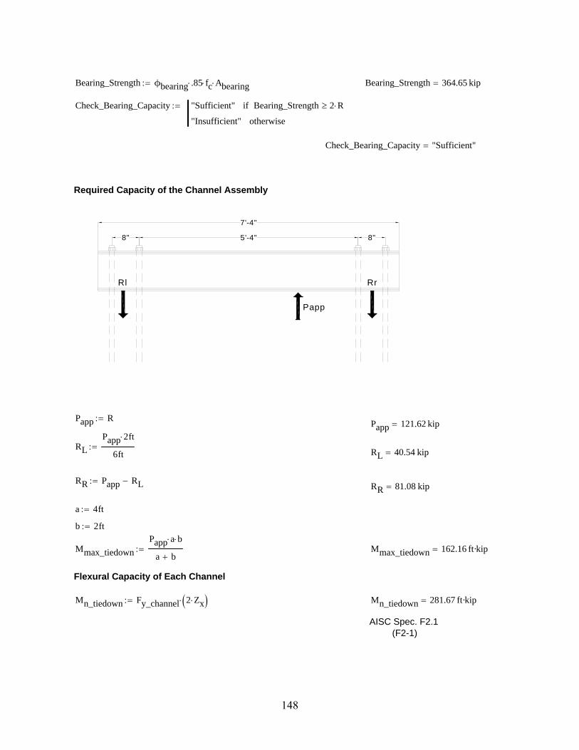
Bearing_Strength ϕbearing .85 fc Abearing Bearing_Strength 364.65 kip
Check_Bearing_Capacity "Sufficient" Bearing_Strength 2 Rif
"Insufficient" otherwise
Check_Bearing_Capacity "Sufficient"
7'-4"
8" 5'-4" 8"
RrRl
Papp
Required Capacity of the Channel Assembly
Papp RPapp 121.62 kip
RL
Papp 2 ft
6ft
RL 40.54 kip
RR Papp RLRR 81.08 kip
a 4ft
b 2ft
Mmax_tiedown
Papp a b
a b Mmax_tiedown 162.16 ft·kip
Flexural Capacity of Each Channel
Mn_tiedown Fy_channel 2 Zx Mn_tiedown 281.67 ft·kip
AISC Spec. F2.1(F2-1)
148

Check_Flexure_Channels "Sufficient" Mn_tiedown Mmax_tiedownif
"Insufficient" otherwise
Check_Flexure_Channels "Sufficient"
Buckling Check of Each Channel
Treated as 2 separate channels
λf
bf
2 tf
λf 3.16
λwh
tw
λw 23.53
λpf .38E
Fy_channel
λpf 9.15
AISC Spec. B4λpw 3.76
E
Fy_channel
λpw 90.55
AISC Spec. B4
Check_Flange_Compact "Compact" λpf λfif
"Not Compact" otherwise
Check_Flange_Compact "Compact"
AISC Spec. B4Check_Web_Compact "Compact" λpw λwif
"Not Compact" otherwise
Check_Web_Compact "Compact"
AISC Spec. B4
Bracing Check of Each Channel
Lb bLb 2 ft
Lp 1.76 ryE
Fy_channel
Lp 2.69 ft
AISC Spec. F2.2(F2-5)
Bracing_Check "Braced" Lp Lbif
"Unbraced" otherwise
Bracing_Check "Braced"
149

Checking Channel Assembly
Iy_unit 2 Iy Achannel x_bar1.75in
2
2
Iy_unit 52.52 in
4
ry_unit
Iy_unit
Achannel
ry_unit 2.44 in
Lp_unit 1.76 ry_unitE
Fy_channel
Lp_unit 103.49 in
bf_unit 2 bf 1.75inbf_unit 8.09 in
tw_unit 2 tw 1.75intw_unit 2.77 in
λf_unit
bf_unit
2 tf
λf_unit 8.07
λw_unith
tw_unit
λw_unit 4.33
Check_Flange_Compact_Unit "Compact" λpf λf_unitif
"Not Compact" otherwise
Check_Flange_Compact_Unit "Compact"
Check_Web_Compact_Unit "Compact" λpw λw_unitif
"Not Compact" otherwise
Check_Web_Compact_Unit "Compact"
Bracing_Check_Unit "Braced" Lp_unit Lbif
"Unbraced" otherwise
Bracing_Check_Unit "Braced"Weld Design
Vweld max RL RR Vweld 81.08 kip
tpl .5in
bpl 5in
Q tpl bpl tpl
2
h
2
Q 15.62 in
3
Iweld 2 Ix 2 tpl bpl tpl
2
h
2
2
1
12
bpl tpl3
Iweld 519.42 in
4
150

Required_Load_per_FootVweld Q
Iweld Required_Load_per_Foot 29.27
kip
ft
Weld_Size3
8in
Felectrode 70ksi
FW .6 Felectrode 42 ksi AISC Spec. J2Table J2.5
ϕweld .75
Throat .707 Weld_Size
Required_Length_Per_FootRequired_Load_per_Foot
ϕweld FW Throat Required_Length_Per_Foot 3.5
in
ft
Specify 4" per foot of Weld
AISC Spec. J2.4(J2-3)
Tie-Down Design
Tmax Tn_blowout 390.6 ft·kip
Vmax 43.4 kip
Mmax 195.3 ft·kip
151

Torsion and Flexure Design Calculations
Input and Properties
Shaft
Diameter of the Shaft ds 30in
Concrete Strength fc 5178psi
Lenth of Shaft Ls 36in
Hoop Steel
Hoop Steel Area Ahoop .11in2
Hoop Steel Diameter dhoop .375in
Spacing of Hoop Steel shoop 2.5in
Yield Strength of Hoop Steel fy_hoop 60ksi
Centerline of Hoop Steel Diamter dh 27in
Longitudinal SteelAlong .2in
2Longitudinal Steel Area
dlong .5inLongitudinal Steel Diameterfy_long 60ksiYield Strength of Longitudinal Steelnlong 24Number of Long Steel Bars
Torsional Stiffener PlatesThickness of the plate t 1in
Width of the plate b 1in
Length of plate L 7in
Yield strength of the plate fy_plate 50ksi
Flexural Stiffener Plates
Width of the stiffener plates bflex_plate 1in
Thickness of the stiffener plates tflex_plate 1in
Length of the stiffener plates Lflex_plate 3in
Embedded Pipe
Thickness of the pipe tpipe .465in
Diameter of the pipe dpipe 16in
Fy_pipe 42ksi
Fu_pipe 58ksi
Moment Arm Tors_Moment_Arm 9ftFlex_Moment_Arm 8ft
Input and Properties
152

STIFFENER DESIGNCalculation of Capacity with Anchor Bolts
Input
Shaft
Diameter of the Shaft ds 30 in
Concrete Strength fc 5.18 ksi
Equivalent Anchor Bolt
Diameter of the bolt do 1.5in
Center-to-center diameter of bolts db 20in
Number of bolts No_Bolts_equiv 12
Yield strength of bolts fy_bolt_equiv 105ksi
Concrete Breakout Equivalent Torsional Strength
Based on ACI 318 Appendix D - Design requirements for shear loading
coverds db
2
cover 5 in
ca1
db
2
2
3.25ds
2
2db
2
2
db
2
3.25
ca1 3.85 in
A360deg
No_Bolts_equiv
A 30 deg
chord_group 2ds
2 sin
A
2
chord_group 7.76 in
Amin_group 2 asin3.0 ca1
ds
Amin_group 45.24 deg
Check_Group_Effect "Group Effect" A Amin_groupif
"No Group Effect" otherwise
Check_Group_Effect "Group Effect"
AVc No_Bolts_equiv chord_group 1.5 ca1AVc 537.55 in
2
AVco 4.5 ca12
AVco 66.57 in
2
le 8 dole 12 in
153
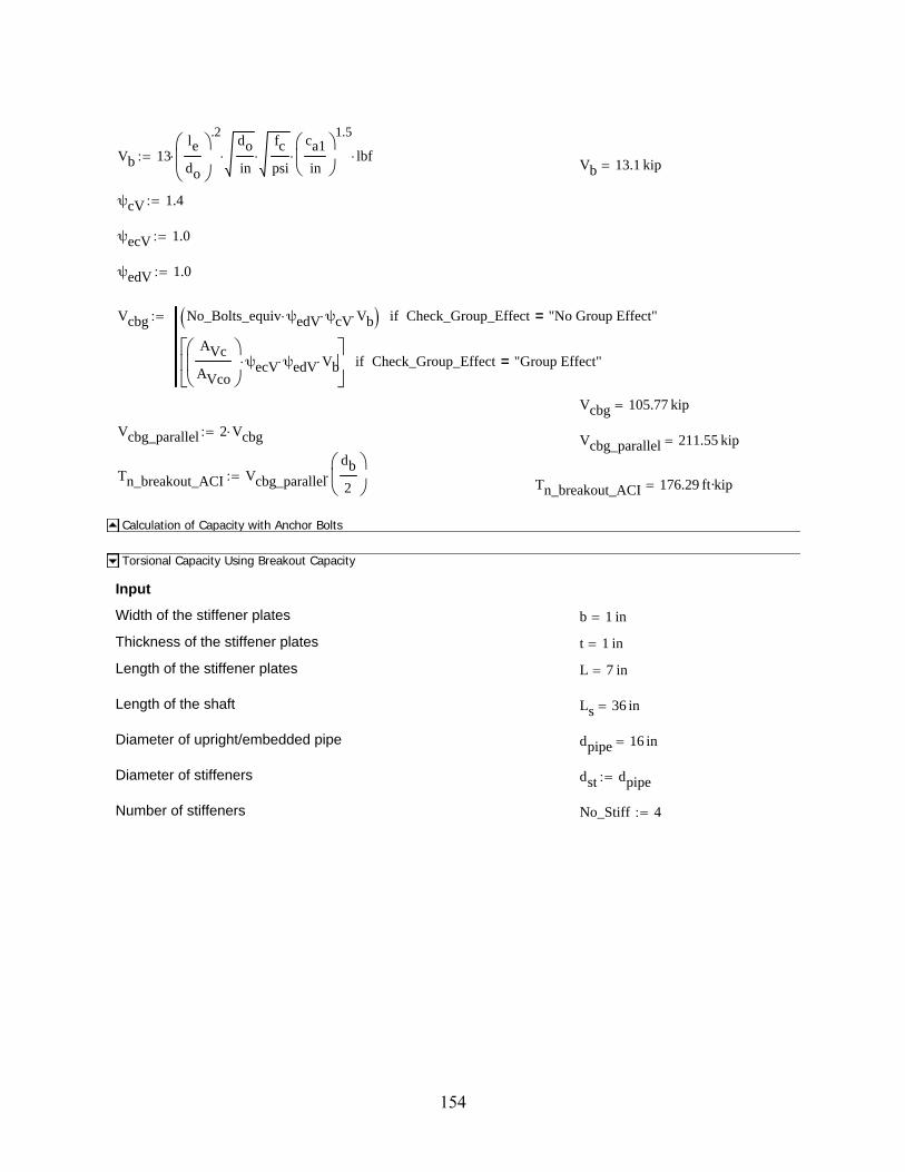
Vb 13le
do
.2
do
in
fc
psi
ca1
in
1.5
lbfVb 13.1 kip
ψcV 1.4
ψecV 1.0
ψedV 1.0
Vcbg No_Bolts_equiv ψedV ψcV Vb Check_Group_Effect "No Group Effect"=if
AVc
AVco
ψecV ψedV Vb
Check_Group_Effect "Group Effect"=if
Vcbg 105.77 kip
Vcbg_parallel 2 VcbgVcbg_parallel 211.55 kip
Tn_breakout_ACI Vcbg_parallel
db
2
Tn_breakout_ACI 176.29 ft·kip
Calculation of Capacity with Anchor Bolts
Torsional Capacity Using Breakout Capacity
Input
Width of the stiffener plates b 1 in
Thickness of the stiffener plates t 1 in
Length of the stiffener plates L 7 in
Length of the shaft Ls 36 in
Diameter of upright/embedded pipe dpipe 16 in
Diameter of stiffeners dst dpipe
Number of stiffeners No_Stiff 4
154

L breakout
Avc
Concrete Breakout Equivalent Torsional Strength
Based on ACI 318 Appendix D - Design requirements for shear loading
coverds dst
2 cover 7 in
ca1
dst
2
2
3.25ds
2
2dst
2
2
dst
2
3.25 ca1 4.99 in
A360deg
No_Stiff A 90 deg
chord_group 2ds
2 sin
A
2
chord_group 21.21 in
Amin_group 2 asin3.0 ca1
ds
Amin_group 59.93 deg
Check_Group_Effect "Group Effect" A Amin_groupif
"No Group Effect" otherwise
Check_Group_Effect "No Group Effect"
lbreakout L 2 1.5ca1 lbreakout 21.98 in
AVc min lbreakout Ls 3 ca1 AVc 329.43 in2
AVco 4.5 ca12
AVco 112.27 in2
le L le 7 in
155

Vb 13le
b
.2
b
in
fc
psi
ca1
in
1.5
lbf Vb 15.41 kip
Vcbg
AVc
AVco
ψecV ψedV ψcV Vb Vcbg 63.31 kip
Vcbg_parallel 2 Vcbg Vcbg_parallel 126.62 kip
Vc Vcbg_parallel No_Stiff Vc 506.46 kip
Tn_breakout_plate Vc
dst
2
Tn_breakout_plate 337.64 ft·kip
Torsional Capacity Using Breakout Capacity
Torsional Capacity Using Side-Face Blowout Capacity
Input
Width of the stiffener plates b 1 in
Thickness of the stiffener plates t 1 in
Length of the stiffener plates L 7 in
Length of the shaft Ls 36 in
Diameter of upright/embedded pipe dpipe 16 in
Diameter of stiffeners dst dpipe
Number of stiffeners No_Stiff 4
Concrete Breakout Equivalent Torsional Strength
Based on ACI 318 Appendix D
ca1
dst
2
2
3.25ds
2
2dst
2
2
dst
2
3.25 ca1 4.99 in
Abrg L b 7 in2
Nsb 200 ca1 Abrg fc.5
psi.5
Nsb 190.19 kip
Tn_blowout No_Stiff Nsbdst
2 Tn_blowout 507.17 ft·kip
Torsional Capacity Using Side-Face Blowout Capacity
156
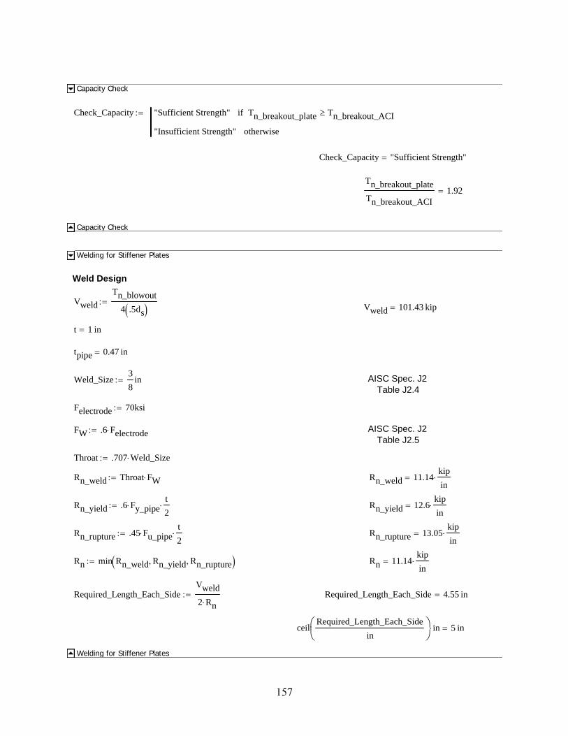
Capacity Check
Check_Capacity "Sufficient Strength" Tn_breakout_plate Tn_breakout_ACIif
"Insufficient Strength" otherwise
Check_Capacity "Sufficient Strength"
Tn_breakout_plate
Tn_breakout_ACI1.92
Capacity Check
Welding for Stiffener Plates
Weld Design
Vweld
Tn_blowout
4 .5ds
Vweld 101.43 kip
t 1 in
tpipe 0.47 in
Weld_Size3
8in AISC Spec. J2
Table J2.4
Felectrode 70ksi
FW .6 Felectrode AISC Spec. J2Table J2.5
Throat .707 Weld_Size
Rn_weld Throat FW Rn_weld 11.14kip
in
Rn_yield .6 Fy_pipet
2 Rn_yield 12.6
kip
in
Rn_rupture .45 Fu_pipet
2 Rn_rupture 13.05
kip
in
Rn min Rn_weld Rn_yield Rn_rupture Rn 11.14kip
in
Required_Length_Each_SideVweld
2 Rn Required_Length_Each_Side 4.55 in
ceilRequired_Length_Each_Side
in
in 5 in
Welding for Stiffener Plates
157

Tn_breakout_ACI 176.29 ft·kip
Tn_breakout_plate 337.64 ft·kip
Tn_blowout 507.17 ft·kip
FLEXURAL CAPACITY
Equivalent Bolt Flexural Capacity
Input
Shaft
Diameter of the Shaft ds 30 in
Concrete Strength fc 5.18 ksi
Equivalent Anchor Bolt
Diameter of the bolt do 1.5in
Center-to-center diameter of bolts db 20in
Number of bolts No_Bolts_equiv 12
Yield strength of bolts fu_bolt_equiv 125ksi
Calculate flexural capacity...
Ab πdo
2
2
Ab 1.77 in2
Mn_bolt Ab fu_bolt_equiv No_Bolts_equivdo
4 Mn_bolt 82.83 ft·kip
Equivalent Bolt Flexural Capacity
Flexural Capacity of Shaft
Check Flexural Capacity of ShaftInput
Rds
215 inRadius of Shaft
As πds
2
2
Area of shaft
Longitudinal Reinforcementnlong 24Number of Longitudinal Barsfy_long 60 ksiYield Strength of Longitudinal Reinforcement
Along 0.2 in2
Longitudinal Steel Areanlong_yield 17Number of Bars Yielded (Assumption)
158

Embedded Pipe
Apipe 24in .688 inCross sectional area of pipedpipe 16 inInside diameter of pipefy_pipe 50ksiYield Strength of Pipe
Calculations Using ACI Stress Block at the Point Below the Embedded Pipe
β1 fc .85 fc 4000psiif
.65 fc 8000psiif
.85 .05fc 4000psi
1000psi
4000psi fc 8000psiif
β1 fc 0.79
ACI 10.2.7.3
Acomp
nlong_yield Along fy_long .85 fc
Acomp 46.35 in2
Acompcircle h( ) R2
acosR h( )
R
R h( ) 2 R h h2
Acomp
a root Acompcircle h( ) h 0in R a 3.51 in
ca
β1 fc c 4.44 in
c = 4.35 in.
y = 2.9 in.
17 Bars Below Yield Line
y .002c
.003 y 2.96 in
159

dbar
9.2502
12.0237
15
17.9763
20.7498
23.1314
25.0189
26.1677
in
dbars0
7
i
dbariAlong 2
26.5in Along
nlong_yield Along dbars 19.13 in
Mn_shaft nlong_yield Along fy_long dbarsa
2
Mn_shaft 295.28 ft·kip
Flexural Capacity of Shaft
Flexural Capacity of Pipe
Z 112in3
Embedded Pipe
Apipe 28.5in2
Cross sectional area of pipe
dpipe 16 inInside diameter of pipePipe wall thickness tpipe 0.47 in
Fy_pipe 42 ksiYield Strength of Pipe
Diameter to thickness ratio D_t 43.0
Length of the pipe Lpipe 3ft
E 29000ksi
Determine Shear Strength of Round HSS
Lv
Lpipe
2
Fcr_1 max1.6 E( )
Lv
dpipeD_t( )
5
4
.78 E( )
D_t( )
3
2
Fcr_1 397.29 ksi
160
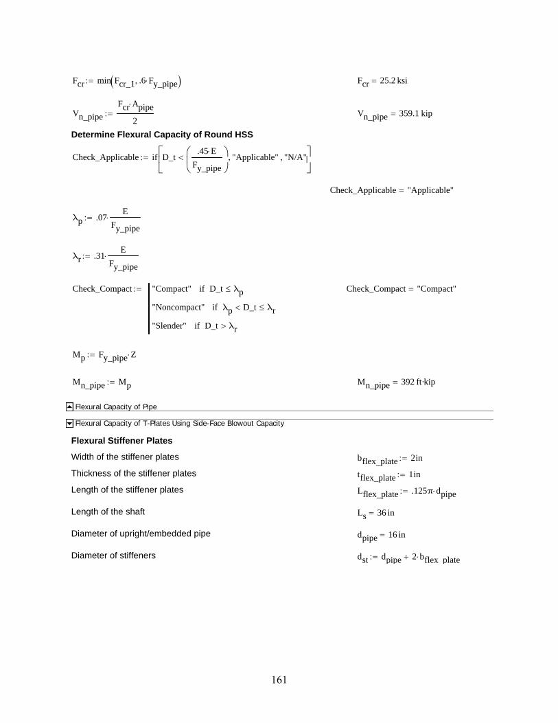
Fcr min Fcr_1 .6 Fy_pipe Fcr 25.2 ksi
Vn_pipe
Fcr Apipe
2 Vn_pipe 359.1 kip
Determine Flexural Capacity of Round HSS
Check_Applicable if D_t.45 E
Fy_pipe
"Applicable" "N/A"
Check_Applicable "Applicable"
λp .07E
Fy_pipe
λr .31E
Fy_pipe
Check_Compact "Compact" D_t λpif
"Noncompact" λp D_t λrif
"Slender" D_t λrif
Check_Compact "Compact"
Mp Fy_pipe Z
Mn_pipe Mp Mn_pipe 392 ft·kip
Flexural Capacity of Pipe
Flexural Capacity of T-Plates Using Side-Face Blowout Capacity
Flexural Stiffener Plates
Width of the stiffener plates bflex_plate 2in
Thickness of the stiffener plates tflex_plate 1in
Length of the stiffener plates Lflex_plate .125π dpipe
Length of the shaft Ls 36 in
Diameter of upright/embedded pipe dpipe 16 in
Diameter of stiffeners dst dpipe 2 bflex plate
161

p p _p
Concrete Breakout Equivalent Flexural Strength
Based on ACI 318 Appendix D
ca1
dst
2
2
3.25ds
2
2dst
2
2
dst
2
3.25 ca1 3.85 in
Abrg Lflex_plate bflex_plate Abrg 12.57 in2
Nsb 200 ca1 Abrg fc.5
psi.5
Nsb 196.22 kip
Mn_blowout Nsb dst Mn_blowout 327.03 ft·kip
Flexural Capacity of T-Plates Using Side-Face Blowout Capacity
Flexural Capacity Using Breakout Capacity
Input
Width of the stiffener plates bflex_plate 1in
Thickness of the stiffener plates tflex_plate 1 in
Length of the stiffener plates Lflex_plate 7in
Length of the shaft Ls 36 in
Diameter of upright/embedded pipe dpipe 16 in
Diameter of stiffeners dst dpipe 4in
Number of stiffeners No_Stiff 4
Concrete Breakout Equivalent Flexural Strength
Based on ACI 318 Appendix D - Design requirements for shear loading
coverds dst
2 cover 5 in
ca1
dst
2
2
3.25ds
2
2dst
2
2
dst
2
3.25 ca1 3.85 in
A360deg
No_Stiff A 90 deg
chord_group 2ds
2 sin
A
2
chord_group 21.21 in
162

Amin_group 2 asin3.0 ca1
ds
Amin_group 45.24 deg
Check_Group_Effect "Group Effect" A Amin_groupif
"No Group Effect" otherwise
Check_Group_Effect "No Group Effect"
lbreakout tflex_plate 2 1.5ca1 lbreakout 12.54 in
AVc min lbreakout Ls 3 ca1 AVc 144.67 in2
AVco 4.5 ca12
AVco 66.57 in2
le Lflex_plate le 7 in
Vb 13le
tflex_plate
.2
bflex_plate
in
fc
psi
ca1
in
1.5
lbf Vb 10.41 kip
Vcbg
AVc
AVco
ψecV ψedV ψcV Vb Vcbg 31.68 kip
Vcbg_parallel 2 Vcbg Vcbg_parallel 63.37 kip
Vc Vcbg_parallel No_Stiff Vc 253.47 kip
Mn_breakout Vc
dst
2
Mn_breakout 211.23 ft·kip
Flexural Capacity Using Breakout Capacity
Mn_bolt 82.83 ft·kip
Mn_pipe 392 ft·kip
Mn_shaft 295.28 ft·kip
Mn_blowout 327.03 ft·kip
Mn_breakout 211.23 ft·kip
163
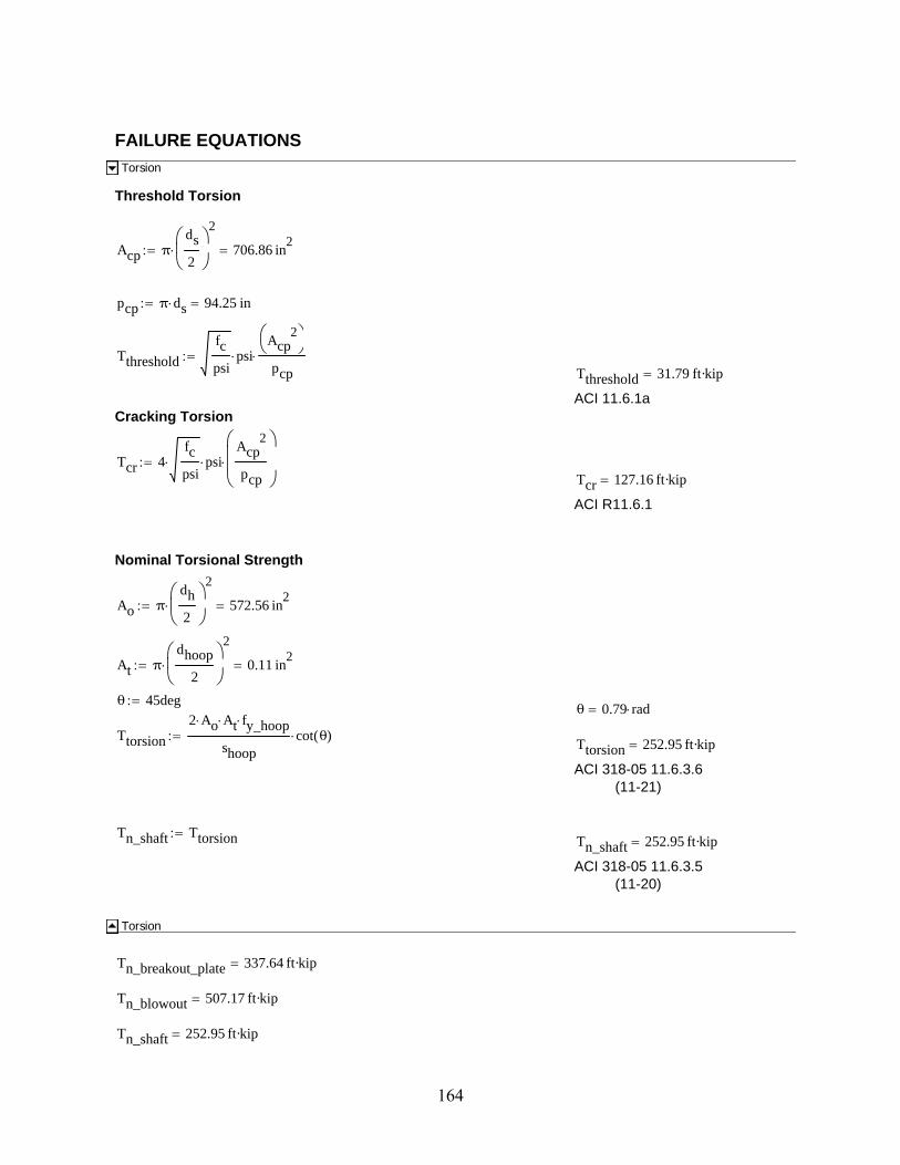
FAILURE EQUATIONS
Torsion
Threshold Torsion
Acp πds
2
2
706.86 in2
pcp π ds 94.25 in
Tthreshold
fc
psipsi
Acp2
pcp
Tthreshold 31.79 ft·kip
ACI 11.6.1aCracking Torsion
Tcr 4fc
psi psi
Acp2
pcp
Tcr 127.16 ft·kip
ACI R11.6.1
Nominal Torsional Strength
Ao πdh
2
2
572.56 in2
At πdhoop
2
2
0.11 in2
θ 45degθ 0.79 rad
Ttorsion
2 Ao At fy_hoop
shoopcot θ( )
Ttorsion 252.95 ft·kip
ACI 318-05 11.6.3.6(11-21)
Tn_shaft TtorsionTn_shaft 252.95 ft·kip
ACI 318-05 11.6.3.5(11-20)
Torsion
Tn_breakout_plate 337.64 ft·kip
Tn_blowout 507.17 ft·kip
Tn_shaft 252.95 ft·kip
164

DEVELOPMENT LENGTHS OF FLEXURAL REINF.
Development Length of Longitudinal Bars
Input
Longitudinal SteelAlong 0.2 in
2
Longitudinal Steel Areadlong 0.5 in
Longitudinal Steel Diameterfy_long 60 ksiYield Strength of Longitudinal Steel
Development Length of Longitudinal Reinforcement
Ψt 1.3 ACI 318-05 12.5.2Ψe 1.0
Ψs 1.0
λ 1.0
Cb_Ktr 2.5in ACI 318-05 12.2.3
ldh_long3
40
fy_long
fc
psipsi
Ψt Ψe Ψs λ
Cb_Ktr
dlong
dlongldh_long 8.13 in
ACI 318-05 12.2.3
ld_long ldh_long ld_long 8.13 in
ACI 318-05 12.2.5
ld_l ceilld_long
in
in ld_l 9 in
Development Length of Longitudinal Bars
Length of Shaft Required
Length of Stiffeners L 7 in
Length of Breakout lbreakout 12.54 in
Length of Shaft Ls 36 in
Development Length of Longitudinal Reinforcement ld_l 9 in
Required Cover c_cover 2.5in
165

Required Length of Shaft Based on Breakout and Development Length
lshaft lbreakout c_cover ld_llshaft 24.04 in
Check_Shaft_Length if Ls lshaft "Sufficient" "Not Sufficient"
Check_Shaft_Length "Sufficient"
Length of Shaft Required
SUPERSTRUCTURE Superstructure Assembly Strength - Pipes
Superstructure Test Assembly Pipe
Pipe Properties - HSS 16x.500
Design Wall Thickness tpipe .465in
Cross Sectional Area of Pipe Apipe 22.7in2
Diameter to Wall Thickness Ratio D_t 34.4
Nominal Weight Wpipe 82.85lbf
ft
Moment of Inertia Ipipe 685in4
Elastic Section Modulus Spipe 85.7in3
Radius of Gyration rpipe 5.49in
Plastic Section Modulus Zpipe 112in3
Diameter of the Pipe Dpipe 20in
Torsional Constant Jpipe 1370in4
HSS Torsional Constant Cpipe 171in3
Yield Strength Fy_pipe 42 ksi
Ultimate Strength Fu_pipe 58 ksi
Modulus of Elasticity E 29000ksi
Length of Short Superstructure Pipe Ls_pipe 17in
Length of Long Superstructure Pipe Ll_pipe 9ft
166
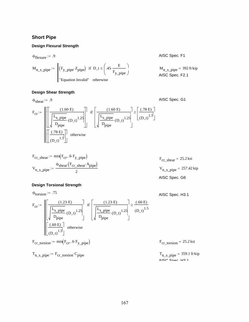
Short Pipe
Design Flexural Strength
ϕflexure .9 AISC Spec. F1
Mn_s_pipe Fy_pipe Zpipe D_t .45E
Fy_pipe
if
"Equation Invalid" otherwise
Mn_s_pipe 392 ft·kip
AISC Spec. F2.1
Design Shear Strength
ϕshear .9 AISC Spec. G1
Fcr1.60 E( )
Ls_pipe
DpipeD_t( )
1.25
1.60 E( )
Ls_pipe
DpipeD_t( )
1.25
.78 E( )
D_t( )1.5
if
.78 E( )
D_t( )1.5
otherwise
Fcr_shear min Fcr .6 Fy_pipe Fcr_shear 25.2 ksi
Vn_s_pipe
ϕshear Fcr_shear Apipe
2 Vn_s_pipe 257.42 kip
AISC Spec. G6
Design Torsional Strength
ϕtorsion .75 AISC Spec. H3.1
Fcr1.23 E( )
Ls_pipe
DpipeD_t( )
1.25
1.23 E( )
Ls_pipe
DpipeD_t( )
1.25
.60 E( )
D_t( )1.5
if
.60 E( )
D_t( )1.5
otherwise
Fcr_torsion min Fcr .6 Fy_pipe Fcr_torsion 25.2 ksi
Tn_s_pipe Fcr_torsion Cpipe Tn_s_pipe 359.1 ft·kip
AISC Spec H3 1
167

AISC Spec. H3.1
Design Axial Strengthϕcomp .90
λr .31E
Fy_pipe
λr 214.05
λp .07E
Fy_pipe
λ "Compact" D_t λpif
"Noncompact" λp D_t λrif
"Slender" D_t λrif
λ "Compact"
AISC Spec. B4
ks_pipe .5
Fe_shortπ
2E
ks_pipe
Ls_pipe
rpipe
2
Fe_short 1.19 105
ksi
AISC Equation E3-4
Fcr_short .658
Fy_pipe
Fe_short
Fy_pipe
Fe_short .44 Fy_pipeif
.877 Fe_short Fe_short .44 Fy_pipeif
Pn_s_pipe ϕcomp Fcr_short Apipe Pn_s_pipe 857.93 kip
AISC Equation E3-1
Summary for Short Pipe
Flexural Strength Mn_s_pipe 392 ft·kip
Shear Strength Vn_s_pipe 257.42 kip
Torsional Strength Tn_s_pipe 359.1 ft·kip
Axial Strength Pn_s_pipe 857.93 kip
168

Long Pipe
Design Flexural Strength
ϕflexure 0.9 AISC Spec. F1
Mn_l_pipe ϕflexure Fy_pipe Zpipe D_t .45E
Fy_pipe
if
"Equation Invalid" otherwise
Mn_l_pipe 352.8 ft·kip
AISC Spec. F2.1
Design Shear Strength
ϕshear 0.9 AISC Spec. G1
Fcr1.60 E( )
Ll_pipe
DpipeD_t( )
1.25
1.60 E( )
Ll_pipe
DpipeD_t( )
1.25
.78 E( )
D_t( )1.5
if
.78 E( )
D_t( )1.5
otherwise
Fcr_shear min Fcr .6 Fy_pipe Fcr_shear 25.2 ksi
Vn_l_pipe
ϕshear Fcr_shear Apipe
2 Vn_l_pipe 257.42 kip
AISC Spec. G6
Design Torsional Strength
ϕtorsion 0.75 AISC Spec. H3.1
Fcr1.23 E( )
Ll_pipe
DpipeD_t( )
1.25
1.23 E( )
Ll_pipe
DpipeD_t( )
1.25
.60 E( )
D_t( )1.5
if
.60 E( )
D_t( )1.5
otherwise
Fcr_torsion min Fcr .6 Fy_pipe Fcr_torsion 25.2 ksi
Tn_l_pipe Fcr_torsion Cpipe Tn_l_pipe 359.1 ft·kip
AISC Spec. H3.1
169

Design Axial Strength
ϕcomp .90
λr .31E
Fy_pipe
λr 214.05
λp .07E
Fy_pipe
λ "Compact" D_t λpif
"Noncompact" λp D_t λrif
"Slender" D_t λrif
λ "Compact"
AISC Spec. B4
klong_pipe 2.0
Fe_longπ
2E
klong_pipe
Ll_pipe
rpipe
2
Fe_long 184.9 ksi
AISC Equation E3-4
Fcr_long .658
Fy_pipe
Fe_long
Fy_pipe
Fe_long .44 Fy_pipeif
.877 Fe_long Fe_long .44 Fy_pipeif
Pn_l_pipe ϕcomp Fcr_long Apipe Pn_l_pipe 780.24 kip
AISC Equation E3-1
Summary for Long Pipe
Flexural Strength Mn_l_pipe 352.8 ft·kip
Shear Strength Vn_l_pipe 257.42 kip
Torsional Strength Tn_l_pipe 359.1 ft·kip
Axial Strength Pn_l_pipe 780.24 kip
Superstructure Assembly Strength - Pipes
170

Superstructure Assembly Strength - Connecting Plates
Superstructure Test HSS Connection Plate
Plate Properties - PL1/2" x 32" x 24"
Plate thickness tp .5in
Plate length hp 32in
Plate width bp 24in
Yield strength Fy_plate 50ksi
Ultimate strength Fu_plate 62ksi
Design Tensile Strength
ϕt_yield .9
Pn_yield ϕt_yield Fy_plate tp bpPn_yield 540 kip
AISC Spec. D2aU 1.0 AISC Table D3.1An tp bp AISC D3.2Ae U An
Ae 12 in2
AISC D3.3ϕt_rupt .75
Pn_rupture ϕt_rupt Ae Fu_platePn_rupture 558 kip
Pn_plate min Pn_yield Pn_rupture Pn_plate 540 kip
AISC D2b
171

Design Flexural Strength
ϕflexure 0.9
Ag tp bpAg 12 in
2
Lb 16in
Ip
bp tp3
3
ctp
2
Sp
Ip
c
Sp 4 in3
My Sp Fy_plateMy 16.67 ft·kip
Zp tp
bp
2
tp
2
Zp 1.5 in3
Mp Fy_plate ZpMp 6.25 ft·kip
Mp_yield 1.6 My 1.6 My Mpif
Mp otherwise
Mp_yield 6.25 ft·kip
LTB_Equation_Check "Equation F11-2".08 E( )
Fy_plate
Lb bp tp
2
1.9 E( )
Fy_plateif
"Equation F11-3"Lb bp
tp2
1.9 E( )
Fy_plateif
LTB_Equation_Check "Equation F11-3"
Cb 1.0 AISC F1
Fcr
1.9 E Cb Lb bp
tp2
Fcr 35.87 ksi
Mn_ltb Fcr Sp LTB_Equation_Check "Equation F11-3"=if
Cb 1.52 .274 Lb
bp
tp2
Fy_plate
E
kip in otherwise
Mn_ltb 11.96 ft·kip
Mn_plate ϕflexure Mn_ltb Mn_ltb Mp_yieldif
Mp_yield otherwise
Mn_plate 5.62 ft·kip
172

Design Torsional Strength
ϕtorsion 0.75
Mt_plate ϕtorsion Fy_plate .6Mt_plate 22.5 ksi
Summary for Plate Connector
Tensile Strength Pn_plate 540 kip
Flexural Strength Mn_plate 5.62 ft·kip
Mt_plate 22.5 ksiTorsional Strength
Weld Design
Vweld
Tn_blowout
Tors_Moment_Arm
Vweld 56.35 kip
tp 0.5 in
tpipe 0.47 in
Weld_Size3
16in AISC Spec. J2
Table J2.4
Felectrode 70ksi
FW .6 Felectrode AISC Spec. J2Table J2.5
ϕweld .75
Throat .707 Weld_Size
ϕRn_weld ϕweld Throat FW ϕRn_weld 4.18kip
in
ϕRn_yield .6 Fy_pipe tp ϕRn_yield 12.6kip
in
ϕRn_rupture .45 Fu_pipe tp ϕRn_rupture 13.05kip
in
ϕRn min ϕRn_weld ϕRn_yield ϕRn_rupture ϕRn 4.18kip
in
Required_Length_Each_SideVweld
ϕRn Required_Length_Each_Side 13.5 in
ceilRequired_Length_Each_Side
in
in 14 in
Superstructure Assembly Strength - Connecting Plates
173
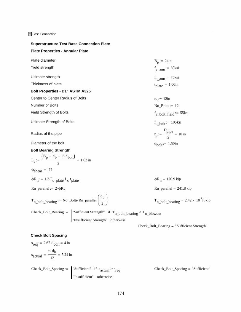
Base Connection
Superstructure Test Base Connection Plate
Plate Properties - Annular Plate
Plate diameter Bp 24in
Yield strength fy_ann 50ksi
Ultimate strength fu_ann 75ksi
Thickness of plate tplate 1.00in
Bolt Properties - D1" ASTM A325
Center to Center Radius of Bolts rb 12in
Number of Bolts No_Bolts 12
Field Strength of Bolts fy_bolt_field 55ksi
Ultimate Strength of Bolts fu_bolt 105ksi
Radius of the pipe rp
Dpipe
210 in
Diameter of the bolt dbolt 1.50in
Bolt Bearing Strength
Lc
Bp db .5 dbolt 2
1.62 in
ϕshear .75
ϕRn 1.2 Fu_plate Lc tplate ϕRn 120.9 kip
Rn_parallel 2 ϕRn Rn_parallel 241.8 kip
Tn_bolt_bearing No_Bolts Rn_paralleldb
2
Tn_bolt_bearing 2.42 103
ft·kip
Check_Bolt_Bearing "Sufficient Strength" Tn_bolt_bearing Tn_blowoutif
"Insufficient Strength" otherwise
Check_Bolt_Bearing "Sufficient Strength"
Check Bolt Spacing
sreq 2.67 dbolt 4 in
sactual
π db
125.24 in
Check_Bolt_Spacing "Sufficient" sactual sreqif
"Insufficient" otherwise
Check_Bolt_Spacing "Sufficient"
174

Check Bolt Shear
Ab π .5 dbolt 2 1.77 in2
Fnv .4 120 ksi 48 ksi
ϕVn ϕshear Ab FnvϕVn 63.62 kip
Vn_parallel ϕVn 2 Vn_parallel 127.23 kip
Tbolt_shear No_Bolts Vn_paralleldb
2
Tbolt_shear 1.27 103
ft·kip
Check_Bolt_Shear "Sufficient Strength" Tbolt_shear Tn_blowoutif
"Insufficient Strength" otherwise
Check_Bolt_Shear "Sufficient Strength"
Weld Design
Weld Connecting Annular Plate to Pipe
tpipe 0.47 in
Weld_Size3
8in AISC Spec. J2
Table J2.4
Felectrode 70ksi
FW .6 Felectrode AISC Spec. J2Table J2.5
Throat .707 Weld_Size
Rn_weld Throat FW Rn_weld 11.14kip
in
Rn_yield .6 Fy_pipe tpipe Rn_yield 11.72kip
in
Rn_rupture .45 Fu_pipe tpipe Rn_rupture 12.14kip
in
Rn min Rn_weld Rn_yield Rn_rupture Rn 11.14kip
in
Rweld Rn π dpipe Rweld 559.72 kip
Tweld Rweld
dpipe
2 Tweld 373.15 ft·kip
Mweld Rweld
dpipe
2 Mweld 373.15 ft·kip
Base Connection
175

Tn_s_pipe 359.1 ft·kip
Tweld 373.15 ft·kip
Mweld 373.15 ft·kip
CONCRETE BLOCKConcrete Block Design - Strut-and-Tie Model
Mmax
Tension Tie
Compression Struts
R
6'-0"
4"4"9'-6"
10'-0"
6"
5'-0" 6'-0"
Based on ACI 318 Appendix A
Vmax
Tn_breakout_plate
Tors_Moment_Arm Vmax 37.52 kip
Mmax Vmax Flex_Moment_Arm Mmax 300.13 ft·kip
d 6ft 8in d 80 in
RMmax
d R 45.02 kip
Node A
θ atan 5ft
d
θ 36.87 deg
CR
sin θ( ) C 75.03 kip
176

T C cos θ( ) T 60.03 kip
Check Reinforcement
No_Bars_Block_Reinf 3
Block_Reinf_Bar_No 8
fy_block_reinf 60ksi
Ablock_reinf No_Bars_Block_Reinf πBlock_Reinf_Bar_No 8
2
2
in2
Ablock_reinf 2.36 in2
Check_Block_Reinf_A "Sufficient" Ablock_reinf fy_block_reinf Tif
"Not Sufficient" otherwise
Check_Block_Reinf_A "Sufficient"
Concrete Block Design - Strut-and-Tie Model
Concrete Block Design - Beam Theory
R
4"
3'-0"
4'-9"
5'-0"
Vblock M
Vblock R Vblock 45.02 kip
Mblock R 3ft 4in( ) Mblock 150.06 ft·kip
From strut-and-tie model...
Ablock_reinf 2.36 in2
177

fy_block_reinf 60 ksi
Check Shear
Check_Shear_B "Sufficient" Ablock_reinf fy_block_reinf Vblockif
"Insufficient" otherwise
Check_Shear_B "Sufficient"
Check Flexure
bblock 30in
hblock 6ft
dblock 5.5ft
Tgiven Ablock_reinf fy_block_reinf Tgiven 141.37 kip
C a( ) .85 fc bblock a
P a( ) C a( ) Tgiven
a root P a( ) a 0in hblock a 1.07 in
β1 fc 0.79
ca
β1 fc c 1.35 in
Mn_block Tgiven dblocka
2
Mn_block 771.24 ft·kip
Check_Flexure_B "Sufficient" Mn_block Mblockif
"Insufficient" otherwise
Check_Flexure_B "Sufficient"
Required Hook Length for a #8 bar
Hook_No_8 12Block_Reinf_Bar_No
8in
Hook_No_8 12 in
ACI 318-05 Fig. 12.5Concrete Block Design - Beam Theory
Summary of Concrete Block Reinforcement
Block_Reinf_Bar_No 8
No_Bars_Block_Reinf 3
Check_Block_Reinf_A "Sufficient"
Check_Shear_B "Sufficient"
Check_Flexure_B "Sufficient"
Summary of Concrete Block Reinforcement
178

Tie-Down Design
Block Properties
Width of the block bblock 30 in
Height of the block hblock 6 ft
Length of the block lblock 10ft
Diameter of the shaft ds 30 in
Length of the shaft lshaft 36in
Weight of concrete wc 150pcf
Maximum shear appliedVmax 37.52 kip
Channel Assembly - 2 C12x30 Channels with 1.75" between
Moment of inertia about strong axis Ix 162in4
Sx 27.0in3
Radius of gyration about strong axis rx 4.29in
Zx 33.8in3
Cross sectional area Achannel 8.81in2
Moment of inertia about weak axisIy 5.12in
4
Radius of gyration about weak axisry .762in
x_bar .674in
Yield strength Fy_channel 50ksi
Modulus of elasticity E 2.9 104
ksi
Web thickness tw .510in
Flange width bf 3.17in
Flange thickness tf .501in
Depth h 12in
179

7'-4"
8" 5'-4" 8"
Vmax
R1
W1 W2
1'-3"
2'-6" 3'-0" 8'-9.5"
Calculate self-weight of block
W1 hblock bblock lblock wc W1 22.5 kip
W2 lshaftπ
4ds
2
wc W2 2.21 kip
Calculate the Load that the Tie-down must resist in each direction
R1
W2
lshaft
2bblock
W1
bblock
2
Vmax lshaft 17.5in bblock
bblock
R1 89.63 kip
R2
Vmax Ll_pipe 3ft 4in W1 W2 3ft 4in( ) 6.67ft
R2 57.02 kip
180

5'-0" 5'-0"
Centerlineof Support
4" 4"
W1 + W2
Vmax
3'-0" 3'-0"
R2
Total Load that the Tie-down must support
RR1
2R2 R 101.84 kip
Check that the load is less than the capacity of the floor
Floor_Capacity 200kip
Check_Floor_Capacity "Sufficient" Floor_Capacity Rif
"Insufficient" otherwise
Check_Floor_Capacity "Sufficient"
Check Bearing Strength of Concrete
Conservatively assume that the load bears on 1 in. of concrete across the length of the block...
Abearing lblock 1 inAbearing 120 in
2
ϕbearing .65
Bearing_Strength ϕbearing .85 fc Abearing Bearing_Strength 343.3 kip
Check_Bearing_Capacity "Sufficient" Bearing_Strength 2 Rif
"Insufficient" otherwise
Check_Bearing_Capacity "Sufficient"
181
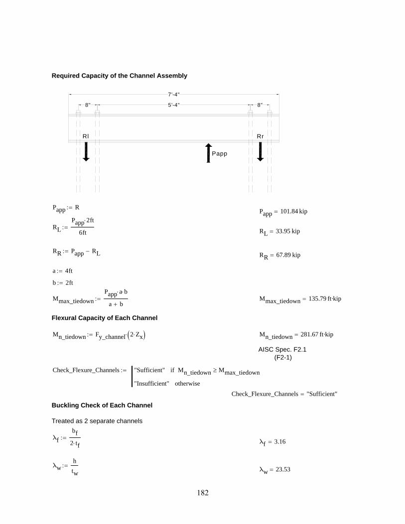
7'-4"
8" 5'-4" 8"
RrRl
Papp
Required Capacity of the Channel Assembly
Papp RPapp 101.84 kip
RL
Papp 2 ft
6ft
RL 33.95 kip
RR Papp RLRR 67.89 kip
a 4ft
b 2ft
Mmax_tiedown
Papp a b
a b Mmax_tiedown 135.79 ft·kip
Flexural Capacity of Each Channel
Mn_tiedown Fy_channel 2 Zx Mn_tiedown 281.67 ft·kip
AISC Spec. F2.1(F2-1)
Check_Flexure_Channels "Sufficient" Mn_tiedown Mmax_tiedownif
"Insufficient" otherwise
Check_Flexure_Channels "Sufficient"
Buckling Check of Each Channel
Treated as 2 separate channels
λf
bf
2 tf
λf 3.16
λwh
tw
λw 23.53
182

λpf .38E
Fy_channel
λpf 9.15
AISC Spec. B4λpw 3.76
E
Fy_channel
λpw 90.55
AISC Spec. B4
Check_Flange_Compact "Compact" λpf λfif
"Not Compact" otherwise
Check_Flange_Compact "Compact"
AISC Spec. B4Check_Web_Compact "Compact" λpw λwif
"Not Compact" otherwise
Check_Web_Compact "Compact"
AISC Spec. B4Bracing Check of Each Channel
Lb bLb 2 ft
Lp 1.76 ryE
Fy_channel
Lp 2.69 ft
AISC Spec. F2.2(F2-5)
Bracing_Check "Braced" Lp Lbif
"Unbraced" otherwise
Bracing_Check "Braced"
183

Checking Channel Assembly
Iy_unit 2 Iy Achannel x_bar1.75in
2
2
Iy_unit 52.52 in
4
ry_unit
Iy_unit
Achannel
ry_unit 2.44 in
Lp_unit 1.76 ry_unitE
Fy_channel
Lp_unit 103.49 in
bf_unit 2 bf 1.75inbf_unit 8.09 in
tw_unit 2 tw 1.75intw_unit 2.77 in
λf_unit
bf_unit
2 tf
λf_unit 8.07
λw_unith
tw_unit
λw_unit 4.33
Check_Flange_Compact_Unit "Compact" λpf λf_unitif
"Not Compact" otherwise
Check_Flange_Compact_Unit "Compact"
Check_Web_Compact_Unit "Compact" λpw λw_unitif
"Not Compact" otherwise
Check_Web_Compact_Unit "Compact"
Bracing_Check_Unit "Braced" Lp_unit Lbif
"Unbraced" otherwise
184

Bracing_Check_Unit "Braced"Weld Design
Vweld max RL RR Vweld 67.89 kip
tpl .5in
bpl 5in
Q tpl bpl tpl
2
h
2
Q 15.62 in
3
Iweld 2 Ix 2 tpl bpl tpl
2
h
2
2
1
12
bpl tpl3
Iweld 519.42 in
4
Required_Load_per_FootVweld Q
Iweld Required_Load_per_Foot 24.51
kip
ft
Weld_Size3
8in
Felectrode 70ksi
FW .6 Felectrode 42 ksi AISC Spec. J2Table J2.5ϕweld .75
Throat .707 Weld_Size
Required_Length_Per_FootRequired_Load_per_Foot
ϕweld FW Throat Required_Length_Per_Foot 2.93
in
ft
Specify 4" per foot of Weld
AISC Spec. J2.4(J2-3)
Tie-Down Design
Tmax Tn_breakout_plate 337.64 ft·kip
Vmax 37.52 kip
Mmax 300.13 ft·kip
185
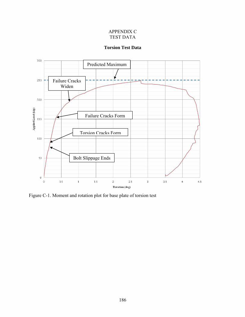
186
APPENDIX C TEST DATA
Torsion Test Data
Figure C-1. Moment and rotation plot for base plate of torsion test
Predicted Maximum
Failure Cracks Widen
Failure Cracks Form
Torsion Cracks Form
Bolt Slippage Ends

187
Figure C-2. Moment and torsional rotation plot for torsion test
Rear of Shaft
Face of Shaft
Outer Base Plate

188
Torsion and Flexure Test Data
Figure C-3. Load and torsional rotation of base plate for torsion and flexure test
Bond loosens
Torsion and flexure cracks form
Failure cracks widen
Failure cracks form

189
Figure C-4. Load and flexural rotation for torsion and flexure test
Base plate to rear of
shaft
Predicted failure
Failure cracks widen
Base plate to face of
shaft
Bond loosens
Bolt slippage ends
Face of shaft to rear
of shaft

190
Figure C-5. Load and torsional rotation for torsion and flexure test
Face of shaft
Base plate
Rear of shaft

191
APPENDIX D DESIGN GUIDELINES
For the purposes of these design guidelines, the design of a typical sign/signal can be
divided into three areas. The first of these would be the superstructure, which would include the
vertical column, horizontal member, connection between the horizontal and vertical members,
and any other design components above the base connection. The second design area would be
the interface with the foundation or the base connection. This second design area can be
subdivided into the superstructure interface and the foundation interface. The last of the design
areas would be the foundation. These design guidelines will only cover the base connection and
the foundation. It is assumed that the superstructure will be designed appropriately using other
FDOT design guidelines. The FDOT offers a MathCAD worksheet program called MastArm
v4.3 on their website that includes the design of the superstructure including the horizontal arm,
connection to the vertical column, the vertical column, and the annular base plate.
For the concerns of this design guideline the interface with the foundation and the
foundation will need to be designed for shear, torsion, and flexure. The foundation interface will
need to be designed to match the annular base plate from the MastArm v4.3 output and the
connecting bolts and welds will need to be designed. The foundation will need to have the
embedded steel pipe and plates, their welded connections, the concrete, and the concrete
reinforcement designed. A design example will be displayed on the following pages.
Base Connection Design
For the design recommended in these design guidelines the information obtained from the
MastArm v4.3 program will be the basis for the design. See Figure D-1 for a clarification of
terminology. For the design of the base plate, the designer will need the following information
from the FDOT program or their own design:
192
• Design loads for shear, flexure, and torsion (Vu, Tu, and Mu) • Superstructure interface base plate sized
The designer should then use this information and their own design knowledge to design
the following for the base connection:
• Size the foundation interface base plate to match the superstructure interface base plate • Size the leveling bolts for design shear, flexure, and torsion • Ensure shear capacity of bolt holes exceeds design shear • Size the leveling nuts
Embedded Pipe Design
For the design of the embedded pipe, the designer will need the following information
from the FDOT program or their own design:
• Design loads for shear, flexure, and torsion (Vu, Tu, and Mu)
• Superstructure monopole sized
• Welded connection from superstructure monopole to superstructure interface base plate sized
The designer should then use this information and their own design knowledge to design
the following for the embedded pipe:
• Size the cross section of the embedded pipe to have the same diameter and wall thickness as the superstructure monopole. The embedded pipe can be either a tapered section or an HSS pipe.
• Size the welded connection from the embedded pipe to the foundation interface base plate to be the same as the welded connection from the superstructure monopole to the superstructure interface base plate.
Embedded Pipe and Torsion Plates Design
For the design of the torsion plates, the designer will need the following information from
the FDOT program or their own design:
• Design loads for shear, flexure, and torsion (Vu, Tu, and Mu) • Diameter and length of the circular pedestal portion of the concrete foundation • Specified concrete strength of the circular pedestal portion of the concrete foundation • Cross section geometry of the embedded pipe

193
The designer should then use this information and their own design knowledge to design
the following for the embedded pipe and plate section (See Figure D-2):
• Determine the number of torsion plates by engineering judgment (minimum of 4, Ntorsion plates)
• Determine the length of torsion plates by engineering judgment (minimum of 6 inches)
• Determine width and thickness of torsion plates by engineering judgment (minimum of 1 inch for each)
• Determine the breakout edge distance, ca1
• Determine the angle available for each plate to breakout
• Determine the angle required for group effect
• Check group effect. If group effect present, reduce the number of plates or diameter of shaft until no group effect occurs.
• Determine length of breakout
• Determine breakout area of one plate
• Determine breakout area of equivalent anchor bolt
• Determine basic shear strength of one torsional plate
• Determine the breakout strength of one torsional plate

194
• Determine the breakout strength of the system of torsional plates
• Determine the torsional strength of the system of plates
• Check to ensure that the Tn breakout is greater than Tu
• Based on the breakout length above, choose depth of embedment for pipe - the breakout should not reach the surface of the concrete
• Size welds to handle design loads (AASHTO LRFD Bridge Design Specifications Section 6.13.3.2.4)
Embedded Pipe and Flexure Plate Design
For the design of the flexural plate, the designer will need the following information from
the FDOT program or their own design:
• Design loads for shear, flexure, and torsion (Vu, Tu, and Mu) • Diameter and length of the circular pedestal portion of the foundation • Specified compressive strength of concrete • Embedded pipe dimensions
The designer should then use this information and their own design knowledge to design
the following for the embedded pipe and plate section (See Figure D-3):
• Assume the number of idealized flexural bearing positions on flexure plate is 2
• Determine thickness of flexure plate, minimum of 1 inch
• Determine diameter of flexure plate, minimum of 2 inches greater than embedded pipe outside diameter (maintain aspect ratio of width to thickness less than 2:1 to avoid prying action)
• Determine the breakout edge distance, ca1
• Determine the angle available for each plate to breakout

195
• Determine the angle required for group effect
• Check group effect. If group effect present, reduce the number of plates or diameter of shaft until no group effect occurs.
• Determine length of breakout
• Determine breakout area of one plate
• Determine breakout area of equivalent anchor bolt
• Determine basic shear strength of one torsional plate
• Determine the breakout strength of one torsional plate
• Determine the breakout strength of the system of torsional plates
• Determine the torsional strength of the system of plates
• Check to ensure that the Mn breakout is greater than Mu
• Based on the breakout length above, verify depth of embedment for pipe - the breakout should not reach the surface of the concrete
• Size welds to handle design loads (AASHTO LRFD Bridge Design Specifications Section 6.13.3.2.4)

196
Concrete Pedestal Reinforcement
For the design of the concrete pedestal reinforcement, the designer will need the following
information from the FDOT program or their own design:
• Design loads for shear, flexure, and torsion (Vu, Tu, and Mu) • Diameter and length of the circular pedestal portion of the foundation • Specified compressive strength of concrete
The designer should then use this information and their own design knowledge to design
the following for the embedded pipe and plate section:
• Reinforcement for flexure (AASHTO LRFD Bridge Design Specifications Section 5.7.3.2.4)
• Reinforcement for torsion (AASHTO LRFD Bridge Design Specifications Equation 5.8.3.6.2-1)

197
Figure D-1. Depiction of the elements described in the design guidelines
Superstructure monopole
Welded connection
Superstructure interface base plate
Bolted connection
Foundation interface base plate
Concrete foundation
Torsional reinforcement
Flexural plate
Embedded pipe and plate section
Flexural reinforcement
Torsional plate
Welded connection
Leveling nut
Superstructure
Base Connection
Foundation

198
Figure D-2. Depiction of dimensions required for torsion plate design
3.0ca1+lpl
≈35° Vb
ca1
AVcp
1.5ca1 1.5ca1 3.0ca1+lpl
≈35°
1.5ca1 1.5ca1
ca1
Length of torsion plates
Width of torsion plates
Thickness of torsion plates

199
Figure D-3. Depiction of dimensions required for flexure plate design
3.0ca1+tfp 1.5ca1 1.5ca1
ca1
Width of flexure plate
3.0ca1+tfp
le
1.5ca1 1.5ca1
AVcp
le
Vbfp
Thickness of flexure plate
Length of bearing area

Sample Design Guidelines
Guidelines for the Design of the Embedded Pipe and Plate Section
The guidelines presented below are intended ONLY to design the embedded pipe and platesection. The remainder of the design should be designed according to applicable FDOT andAASHTO design guidelines.
Input from MastArm Program v4.3
Design Loads
Derived using an example from FDOT Program MastArm Program v4.3
Vu 1.2 1.04 kip 1.6 4.87 kip 9.04 kip
Tu Vu 22 ft 198.88 kip ft
Mu 1.2 18.33 kip ft 1.6 89.59 kip ft 165.34 kip ft
Foundation Geometry
Derived using an example from FDOT Program MastArm Program v4.3
Lshaft 12ft
Diameterbase.pole 16in
twall.pole .375in
Diameterbaseplate.pole 30in
tbaseplate.pole 1.63in
Diametershaft 3.5ft
Diameterboltcircle.pole 23in
Diameterrebar.circle 27.7in
Nolong.rebar 11
Diameterlong.rebar 1.27in
Input from MastArm Program v4.3
Base Connection Design
Step 1) Base Connection Design
Given ϕflex .9 Diameterbase.pole 16 in
fy.pipe 42ksi twall.pole 0.375 in
fu.pipe 58ksi Diameterbaseplate.pole 30 in
fy.baseplate 36ksitbaseplate.pole 1.63 in
fu.baseplate 58ksiDiameterboltcircle.pole 23 in
Es 29000ksi
200

Vu 9.04 kip
Tu 198.88 ft·kip
Mu 165.34 ft·kip
Size the foundation interface base plate
Diameterbaseplate.found Diameterbaseplate.pole 30 in
tbaseplate.found tbaseplate.pole 1.63 in
Size the bolts for design shear, flexure, and torsion
Using threaded rods with A36 steel
Fy.threadedrod 36ksi
Fu.threadedrod 58ksi
Fnt.threadedrod .75 Fu.threadedrod 43.5 ksi AISC Table J3.2
Fnv.threadedrod .4 Fu.threadedrod 23.2 ksi AISC Table J3.2
Select the number of bolts to use
Numberthreadedrod 12
Determine the required diameter of bolts for torsion resolved into shear
Vrequired
Tu
Numberthreadedrod Diameterboltcircle.pole8.647 kip
Athreadedrod.tors
Vrequired
Fnv.threadedrod0.373 in
2
Diameterthreadedrod.tors
4 Athreadedrod.tors π
0.689 in
Round up to the nearest 1/8"
Diameterthreadedrod.tors Ceil Diameterthreadedrod.tors1
8in
Diameterthreadedrod.tors 0.75 in
Determine the required diameter of bolts for flexure resolved into tension
Prequired
Mu
Diameterboltcircle.pole86.264 kip
Athreadedrod.flex
Prequired
Fnt.threadedrod1.983 in
2
Diameterthreadedrod.flex
4 Athreadedrod.flex π
1.589 in
Round up to the nearest 1/8"
Diameterthreadedrod.flex Ceil Diameterthreadedrod.flex1
8in
Diameterthreadedrod.flex 1.625 in
201

Determine the required diameter of bolts for shear
Athreadedrod.shear
Vu
Fnv.threadedrod0.39 in
2
Diameterthreadedrod.shear
4 Athreadedrod.shear π
0.704 in
Round up to the nearest 1/8"
Diameterthreadedrod.shear Ceil Diameterthreadedrod.shear1
8in
Diameterthreadedrod.shear 0.75 in
Use the controlling diameter
Diameterthreadedrod max Diameterthreadedrod.tors Diameterthreadedrod.flex Diameterthreadedrod.shear
Diameterthreadedrod 1.625 in
Determine the length of the threaded rod after determining the size of the nuts and washers
Check minimum spacing and edge distance
sthreadedrod
π Diameterboltcircle.pole Numberthreadedrod
6.021 in
smin8
3Diameterthreadedrod 4.333 in AISC J3.3
Check_spacing if sthreadedrod smin "Sufficient" "Not Sufficient"
Check_spacing "Sufficient"
Lc.threadedrod
Diameterbaseplate.pole Diameterboltcircle.pole 2
3.5 in
Lmin 1.75 Diameterthreadedrod 2.844 in AISC Table J3.4
Check_edgedist if Lc.threadedrod Lmin "Sufficient" "Not Sufficient"
Check_edgedist "Sufficient"
Check bearing strength of bolt holes
Pn.bolthole 1.2 Lc.threadedrod tbaseplate.pole fu.baseplate 397.068 kip
Pmax.bolthole 2.4 Diameterthreadedrod tbaseplate.pole fu.baseplate 368.706 kip
Check_bearing if Pn.bolthole Pmax.bolthole "Sufficient" "Not Sufficient"
Check_bearing "Not Sufficient"
202

Increase threaded rod diameter to 2 in
Diameterthreadedrod 2in
Pmax.bolthole 2.4 Diameterthreadedrod tbaseplate.pole fu.baseplate 453.792 kip
Check_bearing if Pn.bolthole Pmax.bolthole "Sufficient" "Not Sufficient"
Check_bearing "Sufficient"
Size the leveling nuts
Use Heavy Hex nuts
Wlevel.nut 3.125in AISC Table 7-20
Clevel.nut 3.625in AISC Table 7-20AISC Table 7-20
Nlevel.nut 2in AISC Table 7-20
Base Connection Design
Embedded Pipe Design
Step 2) Embedded Pipe Design
Given ϕflex 0.9 Diameterbase.pole 16 in
ϕweld .75 twall.pole 0.375 in
fy.pipe 42ksi Diameterbaseplate.pole 30 in
fu.pipe 58ksi tbaseplate.pole 1.63 in
fy.baseplate 36ksi Diameterboltcircle.pole 23 in
fu.baseplate 58ksi
Es 2.9 104
ksi
Vu 9.04 kip
Tu 198.88 ft·kip
Mu 165.34 ft·kip
Size the cross section of the embedded pipe
Diameterembed.pipe Diameterbase.pole 16 in
twall.embed.pipe twall.pole 0.375 in
203

Size the welded connection from the embedded pipe to the foundation base plate
Vweld.reqd max Vu
Tu
Diameterembed.pipe
149.16 kip
Select weld properties and revise if necessary
Weld_Size1
4in
AISC Spec. J2Table J2.4Felectrode 70ksi
FW .6 Felectrode AISC Spec. J2Table J2.5
Throat .707 Weld_Size
ϕRn_weld ϕweld Throat FW ϕRn_weld 5.568kip
in
ϕRn_yield .6 fy.pipe twall.embed.pipe ϕRn_yield 9.45kip
in
ϕRn_rupture .45 fu.pipe twall.embed.pipe ϕRn_rupture 9.787kip
in
ϕRn min ϕRn_weld ϕRn_yield ϕRn_rupture ϕRn 5.568kip
in
Required_Length_PlateVweld.reqd
ϕRn Required_Length_Plate 26.791 in
Ceil Required_Length_Plate 1in( ) 27 in
Check_Length "Sufficient" π Diameterembed.pipe Required_Length_Plateif
"Not Sufficient" otherwise
Check_Length "Sufficient"
Embedded Pipe Design
Embedded Pipe and Torsion Plates Design
Step 3) Embedded Pipe and Torsion Plates Design
Given ϕflex 0.9 Diameterembed.pipe 16 in
ϕweld 0.75
ϕtor .9twall.embed.pipe 0.375 in
fy.pipe 42 ksi
fu.pipe 58 ksi Diametershaft 42 in
204

Lshaft 12 ftEs 2.9 10
4 ksi
f'c 5500psiVu 9.04 kip
Tu 198.88 ft·kip
L breakout
Avc
Mu 165.34 ft·kip
Based on ACI 318-08 Appendix D - Anchorage to Concrete
Estimate torsion plate section properties and refine if necessary
Ntor.plate 4 Number of torsion plates, minimum of 4
Ltor.plate 6in Length of torsion plate, minimum of 6 in.
btor.plate 1in Width of torsion plate, minimum of 1 in.
ttor.plate 1in Thickness of torsion plate, minimum of 1 in.
coverDiametershaft Diameterembed.pipe
2 cover 13 in
ca1
Diameterembed.pipe
2
2
3.25Diametershaft
2
2Diameterembed.pipe
2
2
Diameterembed.pipe
2
3.25
ca1 8.587 in
A360deg
Ntor.plate1.571 A 90 deg
205
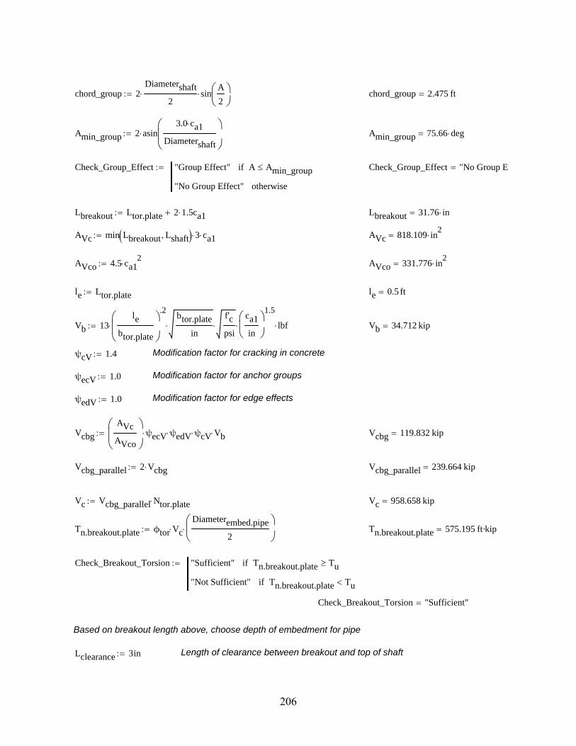
chord_group 2Diametershaft
2 sin
A
2
chord_group 2.475 ft
Amin_group 2 asin3.0 ca1
Diametershaft
Amin_group 75.66 deg
Check_Group_Effect "Group Effect" A Amin_groupif
"No Group Effect" otherwise
Check_Group_Effect "No Group Ef
Lbreakout Ltor.plate 2 1.5ca1 Lbreakout 31.76 in
AVc min Lbreakout Lshaft 3 ca1 AVc 818.109 in2
AVco 4.5 ca12
AVco 331.776 in2
le Ltor.plate le 0.5 ft
Vb 13le
btor.plate
.2
btor.plate
in
f'c
psi
ca1
in
1.5
lbf Vb 34.712 kip
ψcV 1.4 Modification factor for cracking in concrete
ψecV 1.0 Modification factor for anchor groups
ψedV 1.0 Modification factor for edge effects
Vcbg
AVc
AVco
ψecV ψedV ψcV Vb Vcbg 119.832 kip
Vcbg_parallel 2 Vcbg Vcbg_parallel 239.664 kip
Vc Vcbg_parallel Ntor.plate Vc 958.658 kip
Tn.breakout.plate ϕtor VcDiameterembed.pipe
2
Tn.breakout.plate 575.195 ft·kip
Check_Breakout_Torsion "Sufficient" Tn.breakout.plate Tuif
"Not Sufficient" Tn.breakout.plate Tuif
Check_Breakout_Torsion "Sufficient"
Based on breakout length above, choose depth of embedment for pipe
Lclearance 3in Length of clearance between breakout and top of shaft
206

Lembedment Lclearance Lbreakout 1.5 ca1 Lembedment 21.88 in
Lembedment ceilLembedment
in
in Lembedment 22 in
Weld Design for Torsion Plates
Vweld.tor
Tn.breakout.plate
Diametershaft
Vweld.tor 164.341 kip
Select weld properties and revise if necessary
Weld_Size3
8in AISC Spec. J2
Table J2.4
Felectrode 70ksi
FW .6 Felectrode AISC Spec. J2Table J2.5
Throat .707 Weld_Size
ϕRn_weld ϕweld Throat FW ϕRn_weld 8.351kip
in
ϕRn_yield .6 fy.pipe twall.embed.pipe ϕRn_yield 9.45kip
in
ϕRn_rupture .45 fu.pipe twall.embed.pipe ϕRn_rupture 9.787kip
in
ϕRn min ϕRn_weld ϕRn_yield ϕRn_rupture ϕRn 8.351kip
in
Required_Length_Each_PlateVweld.tor
Ntor.plate ϕRn Required_Length_Each_Plate 4.92 in
ceilRequired_Length_Each_Plate
in
in 5 in
Check_Length "Sufficient" Ltor.plate Required_Length_Each_Plateif
"Not Sufficient" otherwise
Check_Length "Sufficient"
Embedded Pipe and Torsion Plates Design
207

Embedded Pipe and Flexure Plate Design
Step 4) Embedded Pipe and Flexure Plate Design
Given
Given ϕflex 0.9 Diameterembed.pipe 16 in
ϕweld 0.75 twall.embed.pipe 0.375 in
ϕtor 0.9Diametershaft 42 in
fy.pipe 42 ksiLshaft 12 ft
fu.pipe 58 ksif'c 5.5 ksi
Es 2.9 104
ksi
Vu 9.04 kip
Tu 198.88 ft·kip
Mu 165.34 ft·kip
Based on ACI 318-08 Appendix D - Anchorage to Concrete
Estimate flexure plate section properties and refine if necessary
Nflex.plate.bear 4 Number of idealized flexural bearing positions on flexure plate
tflex.plate 1in Thickness of flexure plate, minimum of 1 in.
Diameterflex.plate 20in Diameter of flexure plate, minimum of 2 in. greater than embedded plate
coverDiametershaft Diameterflex.plate
2 cover 11 in
ca1
Diameterflex.plate
2
2
3.25Diametershaft
2
2Diameterflex.plate
2
2
Diameterflex.plate
2
3.25
ca1 7.618 in
A360deg
Nflex.plate.bear1.571 A 90 deg
chord_group 2Diametershaft
2 sin
A
2
chord_group 2.475 ft
Amin_group 2 asin3.0 ca1
Diametershaft
Amin_group 65.936 deg
Check_Group_Effect "Group Effect" A Amin_groupif
"No Group Effect" otherwise
Check_Group_Effect "No Group Ef
208

Lbreakout tflex.plate 2 1.5ca1 Lbreakout 23.855 in
AVc min Lbreakout Lshaft 3 ca1 AVc 545.219 in2
AVco 4.5 ca12
AVco 261.182 in2
bflex.plate .5 Diameterflex.plate Diameterembed.pipe bflex.plate 2 in
Lflex.plateπ
8Diameterembed.pipe 2 .5 bflex.plate Lflex.plate 7.069 in
le Lflex.plate le 7.069 in
Vb 13le
tflex.plate
.2
bflex.plate
in
f'c
psi
ca1
in
1.5
lbf Vb 42.394 kip
ψcV 1.4 Modification factor for cracking in concrete
ψecV 1.0 Modification factor for anchor groups
ψedV 1.0 Modification factor for edge effects
Vcbg
AVc
AVco
ψecV ψedV ψcV Vb Vcbg 123.897 kip
Vcbg_parallel 2 Vcbg Vcbg_parallel 247.794 kip
Vc Vcbg_parallel .5 Nflex.plate.bear Vc 495.587 kip
Mn.breakout.plate ϕtor VcDiameterembed.pipe
2
Mn.breakout.plate 297.352 ft·kip
Check_Breakout_Flexure "Sufficient" Mn.breakout.plate Tuif
"Not Sufficient" Mn.breakout.plate Tuif
Check_Breakout_Flexure "Sufficient"
Weld Design for Flexure Plate
Vweld.flex
max Mu Mn.breakout.plate Diameterflex.plate
Vweld.flex 178.411 kip
Select weld properties and revise if necessary
Weld_Size1
4in AISC Spec. J2
Table J2.4
Felectrode 70ksi
209

FW .6 Felectrode AISC Spec. J2Table J2.5
Throat .707 Weld_Size
ϕRn_weld ϕweld Throat FW ϕRn_weld 5.568kip
in
ϕRn_yield .6 fy.pipe twall.embed.pipe ϕRn_yield 9.45kip
in
ϕRn_rupture .45 fu.pipe twall.embed.pipe ϕRn_rupture 9.787kip
in
ϕRn min ϕRn_weld ϕRn_yield ϕRn_rupture ϕRn 5.568kip
in
Required_Length_PlateVweld.flex
ϕRn Required_Length_Plate 32.044 in
ceilRequired_Length_Plate
in
in 33 in
Check_Length "Sufficient" π Diameterembed.pipe Required_Length_Plateif
"Not Sufficient" otherwise
Check_Length "Sufficient"
Embedded Pipe and Flexure Plate Design
Concrete Pedestal Reinforcement
Step 5) Concrete Pedestal Reinforcement
Given Diametershaft 42 in fy.rebar 50ksi
Lshaft 12 ftDiameterhoop.rebar .500in
f'c 5.5 ksiR .5Diametershaft 21 in
Vu 9.04 kipDiameterflex.rebar 1.375in
Tu 198.88 ft·kipDiameterrebar.circle 27.5in
Mu 165.34 ft·kip
Reinforcement for Flexure
Determine properties of flexural reinforcement
Numberflex.rebar Nolong.rebar 11
Aflex.rebar .25 π Diameterflex.rebar2
Assume 8 of the 11 bars yield
nflex.yield 8
210

Calculations Using ACI Stress Block
β1 fc .85 fc 4000psiif
.65 fc 8000psiif
.85 .05fc 4000psi
1000psi
4000psi fc 8000psiif
β1 f'c 0.775
ACI 10.2.7.3
Acomp
nflex.yield Aflex.rebar fy.rebar .85 f'c
Acomp 0.882 ft2
Acompcircle h( ) R2
acosR h( )
R
R h( ) 2 R h h2
Acomp
a root Acompcircle h( ) h 0in R a 6.191 in
ca
β1 f'c c 7.988 in
y .002c
.003 y 5.325 in
c = 7.988 in.
y = 5.325 in.
dbars .5 Diametershaft c y c y dbars 27.657 in
Mn.shaft ϕflex nflex.yield Aflex.rebar fy.rebar dbarsa
2
Mn.shaft 1.094 103
ft·kip
Check_Flexure if Mn.shaft Mu "Sufficient" "Not Sufficient"
Check_Flexure "Sufficient"
211

Reinforcement for Torsion
Ators.rebar π .5 Diameterhoop.rebar 2 0.196 in2
Ao π .5Diameterrebar.circle .5 Diameterlong.rebar .5 Diameterhoop.rebar 2 672.876 in2
stors.rebar 4in
Tn.shaft
ϕtor 2 Ao Ators.rebar fy.rebar
stors.rebarcot 45deg( ) Tn.shaft 247.723 ft·kip
Check_Torsion if Tn.shaft Tu "Sufficient" "Not Sufficient"
Check_Torsion "Sufficient"
Concrete Pedestal Reinforcement
212

213
LIST OF REFERENCES
1. Cook, R.A., and Halcovage, K.M., “Anchorage Embedment Requirements for Signal/Sign Structures,” Florida Department of Transportation, Tallahassee, FL, 2007, 119 pp.
2. Fouad, F.H.; Davidson, J.S.; Delatte, N.; Calvert, E.A.; Chen, S.; Nunez, E.; and Abdalla, R., “Structural Supports for Highway Signs, Luminaires, and Traffic Signals,” National Cooperative Highway Research Program Report 494, Transportation Research Board of the National Academies, Washington, D.C., 2003, pp. 3-16.
3. AASHTO Highway Subcommittee on Bridges and Structures, “Standard Specifications for Structural Supports for Highway Signs, Luminaires, and Traffic Signals,” American Association of State Highway and Transportation Officials, Washington, D.C., Fourth Edition, 2001, pp. 13-1-13-8.
4. Fouad, F.H.; Calvert, E.A., and Nunez, E., “Structural Supports for Highway Signs, Luminaires, and Traffic Signals: Draft Final Report,” Transportation Research Board of the National Academies, Washinton, D.C., September 1997, 170 pp.
5. ACI Committee 318, “Building Code Requirements for Structural Concrete (ACI 318-08) and Commentary,” American Concrete Institute, Farmington Hills, MI, 2008, 473 pp.
6. Dexter, R.J., and Ricker, M.J., “Fatigue-Resistant Design of Cantilevered Signal, Sign, and Light Supports,” National Cooperative Highway Research Program Report 469, Transportation Research Board of the National Academies, Washington, D.C., 2002, pp. 4-9.
7. Kaczinski, M.R.; Dexter, R.J., and Van Dien, J.P., “Fatigue-Resistant Design of Cantilevered Signal, Sign, and Light Supports,” National Cooperative Highway Research Program Report 412, Transportation Research Board of the National Academies, Washington, D.C., 1998, pp.1-19, 56-149.
8. Billingstad, N.A., and Volle, F.I., “Foundation Tube for use as a Foundation for Masts, Posts, Pillars, etc.” 5,836,124 United States, November 17, 1998 (Patent).
9. IEEE Power Engineering Society and the American Society of Civil Engineers, “IEEE Guide for Transmission Structure Foundation Design and Testing (IEEE Std 691-2001),” The Institute of Electrical and Electronics Engineers, New York, New York, 2001.
10. Gates, W., “Wind Farms Dynamics: Not all slopes are created equal,” Power Engineering International, August 2008, Available from http://pepei.pennet.com/Articles/Article_Display.cfm?ARTICLE_ID=3227637p=6, Accessed October 31, 2008.a

214
11. Wind Energy Direct, “Tower Guide,” Wind Energy Direct, Available from http://www.windenergydirect.org/tower_guide.pdf, Accessed October 31, 2008.
12. Fuchs, W.; Eligehausen, R., and Breen, J., “Concrete Capacity Design (CCD) Approach for Fastening to Concrete,” ACI Structural Journal, V. 92, No. 1, Jan.-Feb. 1995, pp. 73-94.
13. Furche, J., and Eligehausen, R., “Lateral Blow-out Failure of Headed Studs Near a Free Edge,” Anchors in Concrete – Design and Behavior, SP-130, American Concrete Institute, Farmington Hills, MI, 1991, pp. 235-252.
14. Bae, S.; Bayrak, O.; Jirsa, J.O., and Klingner, R.E., “Effect of Alkali-Silica Reaction/Delayed Ettriginite Formation Damage on Behavior of Deeply Embedded Anchor Bolts,” ACI Structural Journal, V. 106, No. 6, Nov.-Dec. 2009, pp.848-857.
15. American Institute of Steel Construction, “Steel Construction Manual,” American Institute of Steel Construction, Chicago, Thirteenth Edition, 2005, 2190 pp.
16. Collins, T.J., and Garlich, M.G., “Sign Structures Under Watch,” Roads and Bridges, July 1997, Available from http://www.roadsbridges.com/Sign-Structures-under-Watch-article761, Accessed August 13, 2009.
17. AASHTO Highway Subcommittee on Bridges and Structures, “2006 Interim to Standard Specifications for Structural Supports for Highway Signs, Luminaires, and Traffic Signals,” American Association of State Highway and Transportation Officials, Washington, D.C., 2006, pp. 13-1-13-8.
18. State of Florida, Department of Transportation, “Design Standards for Design, Construction, Maintenance, and Utility Operations of the State Highway System,” Index No. 11860, Florida Department of Transportation, Tallahassee, FL, pp. 1-8.
19. Cook, R.A., McVay, M.C., and Canner, I., “Alternatives for Precast Pile Splices, Vol. 2” Florida Department of Transportation, Tallahassee, FL, 143 pp.

215
BIOGRAPHICAL SKETCH
Kathryn Jenner was born in Miami, Florida in March 1986 to parents Stuart and Joann
Jenner. At the age of eight her family relocated to scenic Naples, Florida. In May 2004 Kathryn
graduated with high honors from Gulf Coast High School in Naples. She began attending the
University of Florida in the fall of 2004. In May 2008 Kathryn graduated cum laude from the
University of Florida with a Bachelor of Science in Civil Engineering. She graduated with her
Master of Engineering in May 2010.