altitude management system 2 9 9 2 in · altitude during your flight, you will want to set the...
TRANSCRIPT

AMS 2000™ Altitude Management System
Operation Guide
Shadin AMS 2000
2 9 9 2 In
A l t i t u d e M a n a g e m e n t S ys t e m
For P/N 8900

2
NOTE Before using this information and the product it supports, be sure to read the section covering the product warranty.
6831 Oxford Street
St. Louis Park, MN. 55426 U.S.A.
Sales: (800)-328-0584 Technical Support: (800)-388-2849
While every precaution has been taken in the preparation of this manual, Shadin Avionics assumes no responsibility for errors or omissions. Neither is any liability assumed for damages resulting from the use of this information contained herein. Although it is not required by the FAA, it is recommended that this manual be attached to the FAA-approved flight manual, or always be kept on board for reference.
3
Table Of Contents
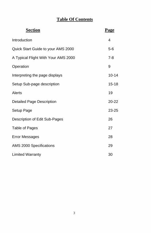
Section Page Introduction 4 Quick Start Guide to your AMS 2000 5-6 A Typical Flight With Your AMS 2000 7-8 Operation 9 Interpreting the page displays 10-14 Setup Sub-page description 15-18 Alerts 19 Detailed Page Description 20-22 Setup Page 23-25 Description of Edit Sub-Pages 26 Table of Pages 27 Error Messages 28 AMS 2000 Specifications 29 Limited Warranty 30

4
INTRODUCTION What is AMS 2000? AMS 2000 is an Altitude Management and Alert System. Its purpose is to alert you when you are approaching or deviating from your target altitude. Other features include alerts when you reach your Decision Height or Minimum Descent Altitude, and a landing gear reminder when you approach your destination altitude. The AMS 2000 also will calculate density altitude and engine performance. These alerts and calculations help you fly safer and easier. AMS 2000 does not act as an auto pilot, or control the aircraft in any way. Think of it as an assistant to you, the pilot, which keeps track of minor details and frees you to fly the aircraft. No longer do you have to keep both eyes on the sky and one on the altimeter. AMS 2000 receives its altitude information from your encoder, and displays it in 100-foot increments. When connected to a Falcon Altitude Encoder or Converter, AMS 2000 displays altitude in 10 foot increments, and also offers a page displaying Instantaneous Vertical Speed (IVS). IVS display does not have the lag inherent in static system VSI displays.

5
Quick-Start guide to your AMS 2000: Read This First
The old saying goes, "when all else fails, read the instructions!" Certainly, you should read the Pilot's Manual for your AMS 2000 to learn the details that will make your flying easier and safer. Until you do, this page will get you started using your AMS 2000. When you first power up the AMS 2000, the unit goes through a 30-second self-test. At the end of the test, the unit will beep once (provided you have connected it to the audio panel or Sonalert™), and the display will flash a test pattern, followed by the software version, and finally show the BAR page. Set the barometric pressure on this page by pressing the knob in briefly (the display will flash, showing you are editing this page) and turning until the correct barometric pressure is shown. Press the knob again and the display will stop flashing and show the pressure reading you have just set. Turn the knob two clicks clockwise to show the ALT page. This page shows the reading currently being reported by your altitude encoder. It is normal to see "EN N-RDY" until your encoder warms up. If you see "EN ERROR", there is likely a problem with the installation, or with your encoder. Consult your installer or avionics shop for further assistance. One more click clockwise will show the DES page, where you set your destination altitude. Press the knob to edit this page, and turn the knob until your destination altitude is shown. Press once again to set the new destination altitude. The AMS 2000 automatically sets your Decision Height to 200 feet above DES, and Minimum Descent Altitude to 400 feet above DES. You can increase these settings by turning the knob to show the DH or MDA pages, and editing them as you did with DES. Finally, turn the knob back (counter-clockwise) until the TALT page is shown. This is your Target Altitude. Push the knob to edit this page, and set your desired cruise altitude. Push once again to set this altitude, and turn the knob one click clockwise to again show ALT. Your AMS 2000 is now set to alert you just before you reach your chosen cruise altitude.

6
As you are flying, you will periodically need to reset your barometric pressure reading. Do this by selecting the BAR page, and editing as you did when you started the AMS 2000. Also, you may select a new target altitude anytime during flight, by selecting and editing the TALT page. If you change your cruising altitude during your flight, you will want to set the target altitude to your new cruise altitude. Simply press the knob twice within one second, while displaying the ALT page and your current altitude will be set as your target. AMS 2000 will then alert you if you deviate. Detailed instructions on the various tasks that the AMS 2000 manages are covered in the remainder of this manual. The brief overview above will get you started, but please read the manual completely for full details on operating your AMS 2000.

7
A TYPICAL FLIGHT WITH YOUR AMS 2000 In this example, it is assumed that a Falcon High-Resolution Altitude Encoder is connected to the AMS 2000. Some AMS 2000 features are not available with conventional encoders. When you first power up the AMS 2000, it will go through self-test, report the software version number and go to the BAR page. You need to set the current altimeter setting on this page. If you have a Falcon High-Resolution Altitude Encoder connected to your AMS 2000, you can also simply set the field elevation, and the AMS 2000 will calculate the altimeter for you. Use one of these methods to set the barometric pressure (edit either the BAR page or the ELV page). Select the DES page, and edit to set your destination altitude. Let's assume 3,300 feet for your destination. Select the TALT page, and edit to set your target altitude. Now, select the ALT page to monitor your altitude and receive alerts. Let's assume your target is 5,000 feet. After takeoff, when you are about 15 seconds from your target, you will see LEVEL___ flash on the AMS 2000 front panel, and it will beep through your audio panel (or Sonalert™). Once you have leveled off at 5,000, AMS 2000 watches to see that you don't deviate more than the BUFR amount. If you do, you will get an audio alert, and the AMS 2000 front panel will remind you of your target altitude and show arrows to indicate climb or descend. Now, ATC tells you to climb to 11,500 feet. As you climb above 5,200 (assuming your BUFR is 200 feet), you'll get a descend warning. Press the knob to silence the audio and restore the display. You can set 11,500 as a new target (from the TALT page), and AMS 2000 will give you a 15-second level-off warning. Or you can wait until you reach 11,500, and press the knob twice (within one second) on the ALT page. This will set your target to your current altitude. AMS 2000 will now warn you if you deviate from this new altitude. ATC also will give you new altimeter settings. Edit the BAR page to show the new altimeter setting.

8
As you descend toward your destination, select MDA or DH depending on the type of approach. Assuming you enabled GEAR during SETUP, you will receive a GEAR alert 1,000 feet above your destination altitude, to remind you to check the status of your landing gear. Continue to descend to receive a Minimum Descent Altitude alert. This alert will happen 400 feet above your destination, unless you have set it higher. If this is an ILS approach, the DH page will alert just before you reach your DH. This will be 200 feet above your destination, unless you have set it higher. If you have previously set the missed approach altitude on the TALT page, when you receive the DH/MDA alert the display will automatically change to the TALT page and display this selected altitude. This is, of course, just a brief overview of the AMS 2000 operation. The operations chapter describes more completely the AMS 2000's operation and features.
9
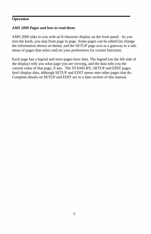
Operation AMS 2000 Pages and how to read them: AMS 2000 talks to you with an 8-character display on the front panel. As you turn the knob, you step from page to page. Some pages can be edited (to change the information shown on them), and the SETUP page acts as a gateway to a sub-menu of pages that select and set your preferences for certain functions. Each page has a legend and most pages have data. The legend (on the left side of the display) tells you what page you are viewing, and the data tells you the current value of that page, if any. The STAND-BY, SETUP and EDIT pages don't display data, although SETUP and EDIT opens onto other pages that do. Complete details on SETUP and EDIT are in a later section of this manual.

10
Interpreting the page displays: Each page has a specific function. The examples below show you what to expect from an AMS 2000 unit that has just been powered up. Turning the knob clockwise takes you through the pages as they are presented here. See table on Page 14. Page reference: Complete details on pages 10 - 15. Page: BAR Meaning: Barometric pressure or "altimeter setting" Display: "BAR 2992" at power-up. Editing: Edit to set the current barometric pressure. Alerts: None generated, GEAR received on this page. Page: TALT Meaning: Target altitude. Display: "TALT 2000" at power-up. Editing: Edit to set target altitude. Alerts: LEVEL___ when 15 seconds from target altitude using the Falcon encoder or the preset level-off alert,
if using another encoder, climb or descend warnings when deviating from target. These warnings are available on all other pages except SETUP, which will flash “LEVEL____” but does not sound.

11
Page: ALT Meaning: Current altitude, as reported by encoder. Display: "ALT XXXX", where XXXX is the current altitude. Editing: This page can't be edited. Push knob twice to set current
altitude as target altitude. Alerts: Receive LEVEL___, climb and descend warnings, and GEAR. Page: DES Meaning: Destination altitude. Display: "DES 0" at power-up. Editing: Edit to set altitude of your destination airfield. This setting is
used to calculate GEAR, Decision Height and Minimum Descent Altitude alerts
Alerts: Receive GEAR. Page: DH Meaning: Decision Height Display: "DH DES?" on power-up. Editing: Edit this page to set your Decision Height. The default is 200
feet above DES, and may not be set lower. DES must be set before DH may be set. The page will show "DES?" until a destination altitude is selected.
Alerts: Receive GEAR and DH alerts. (Note: DH alerts received only
on this page)

12
Page: MDA Meaning: Minimum Descent Altitude Display: "MDA DES?" on power-up. Editing: Edit this page to set your Minimum Descent Altitude. The
default is 400 feet above DES, and may not be set lower. DES must be set before MDA may be set. The page will show "DES?" until a destination altitude is selected.
Alerts: Receive GEAR and MDA alerts. (Note: MDA alerts are
received only on this page) Page: DALT Meaning: Density Altitude display. Display: "DALT OAT?" on power-up. "DALT XXXXX" after setting
Outside Air Temperature, where XXXXX is the current density altitude.
Editing: Edit this page to set the current outside air temperature. The
display may be shown in either degrees Celsius or degrees Fahrenheit, selectable from SETUP
Alerts: Receive GEAR, LEVEL___, climb and descend alerts.

13
Page: PERF Meaning: Engine Performance Ratio Display: "PRF OAT?" on power-up. "PERF XX%" after setting
outside air temperature, where XX% is the current performance ratio of the engine and airframe vs. normal sea-level density altitude.
Editing: Edit this page to set the current outside air temperature. The
display may be shown in either degrees Celsius or degrees Fahrenheit, selectable from the SETUP sub-menu.
Page: DTM Meaning: Down Timer Display: "DTM 0:00” on startup. “DTM X:XX” after setting timer. Editing : Edit this page to set a general purpose timer. This timer can
range from 0 to 9 minutes and 59 seconds (9:59). When it has counted down to 0:00, an alarm is sounded. This alarm is received on all pages, except Setup.
Alerts: Level___, Gear, climb and descent alerts. Page: LTM Meaning: Long Timer. Display: "LTM 0:00” on startup. “LTM X:XX” after setting timer
value. Editing: Edit this page to set a general-purpose timer. This timer can
range from 0 to 9 hours and 59 minutes (9:59)When it has counted down to 0:01 it will then switch to seconds and count down from 0:59 to 0:00 and sound an alarm. This alarm is received on all pages, except Setup.
Alerts: Level___, and Gear alerts.

14
Page: ELV Meaning: Elevation Display: "ELV ----" on power-up. Editing: Edit this page to set altimeter when no barometric pressure
reading is available. Set ELV to the field elevation, and BAR will be calculated automatically. This page will not appear unless a Falcon High-Resolution Altitude Encoder is connected.
Alerts: Receive GEAR warning. Page: SETUP Meaning: Enter SETUP sub-pages. Display: "SETUP" Editing: This page can't be edited. Press the knob to enter the SETUP
sub-pages and set your operating preferences. Alerts: None received.

15
SETUP Sub-Page descriptions: (Note: No alerts are generated or received while viewing or editing the SETUP sub-pages. You must EXIT the sub-pages to once again receive alerts) Sub-page: DIM-BRT Meaning: Display brightness Stored: No. Defaults to full brightness at power-up. Editing : Edit to set one of 8 brightness levels. Sub-page: VOL Meaning: Volume of audio alert tone. Stored: Fixed at Volume = 8 Editing: Edit this page to set the audio tone volume to one of 8 levels.
Tone will sound during editing. (Note: if you have connected a Sonalert™ tone module, this page will only activate and test it. Sonalert™ volume can't be adjusted)
Sub-page: TONE Meaning: Pitch of audio alert tone. Stored: Yes. Editing: Edit this page to set the audio tone pitch to one of 8 levels.
Tone will sound during editing. (Note: if you have connected a Sonalert™ tone module, this page will only activate and test it. Sonalert™ pitch can't be adjusted)

16
Sub-page: LOA Meaning: Level-Off Alert margin. Stored: Fixed at Tone = 5 Editing: Edit this sub-page to select the margin for Level-Off alerts. A
setting of 100 means that you will be given the LEVEL___ alert 100 feet from your target altitude. LOA may be set between 100 and 1,000 feet, in 100-foot increments. This page will not appear if a Falcon High-Resolution Altitude Encoder or Converter is connected. Instead, your Level-Off alert will be calculated in real-time and delivered about 15 seconds before you reach your target altitude.
Sub-page: BUFR Meaning: Altitude tracking buffer size. Stored: Yes. Editing: Edit this sub-page to set the size of the altitude-tracking
buffer. This is the distance above or below the target altitude beyond which you are given an alert. If you select 200 feet, and your target is 5,000 feet, you will get a climb alert when you descend below 4,800 feet. BUFR may be set from 100 to 300 feet. If you have a Falcon High-Resolution Altitude Encoder or Converter connected, BUFR may be set in 10-foot increments. Otherwise, it is set in 100-foot increments.
Sub-Page: STAND-BY Meaning: Select Stand-By operation. Stored: No. Editing: This page can't be edited. Press knob to place unit in stand-by
operation (display shut off, no alerts generated), and press again to re-activate and return to the BAR page of the main menu.
17
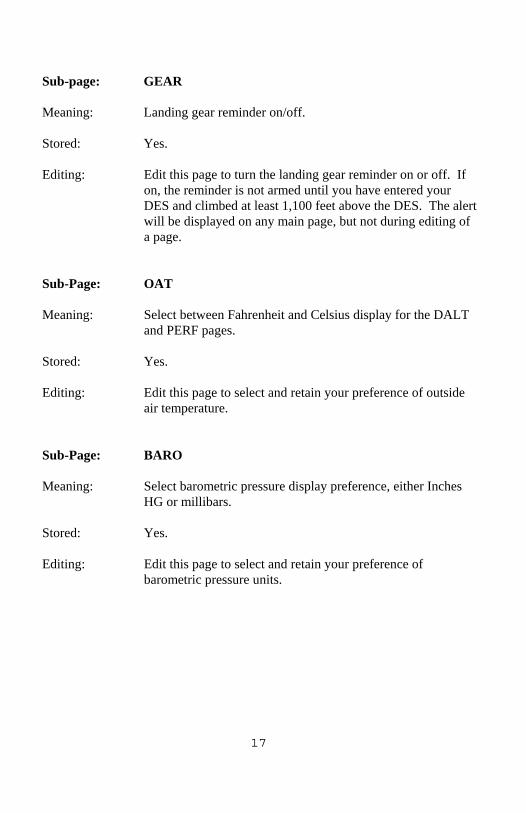
Sub-page: GEAR Meaning: Landing gear reminder on/off. Stored: Yes. Editing: Edit this page to turn the landing gear reminder on or off. If
on, the reminder is not armed until you have entered your DES and climbed at least 1,100 feet above the DES. The alert will be displayed on any main page, but not during editing of a page.
Sub-Page: OAT Meaning: Select between Fahrenheit and Celsius display for the DALT
and PERF pages. Stored: Yes. Editing: Edit this page to select and retain your preference of outside
air temperature. Sub-Page: BARO Meaning: Select barometric pressure display preference, either Inches
HG or millibars. Stored: Yes. Editing: Edit this page to select and retain your preference of
barometric pressure units.

18
Sub-Page: EDIT Meaning: Enter Edit Sub-Pages. Stored: N/A Editing: This page cannot be edited. Press knob to enter the EDIT
sub-pages to chose which pages are shown by setting them to either “show” or “omit.” See table on page 26 to describe what pages can be hidden.
Sub-page: EXIT Meaning: Return to main pages and normal operation. Stored: N/A Editing: This sub-page can't be edited. Press the knob to return to the
main pages and normal operation.

19
Alerts: Your AMS 2000 is talking to you AMS 2000 will alert you when certain conditions occur. These alerts are both audible and visual. A brief tone sounds when an alert is issued, and the display will flash at full brightness with a message. To acknowledge an alert, press the knob and the display will stop flashing. Without an acknowledgement, the alerts will stop after a short time. However, in the case of altitude deviation alerts, the display will continue to show a flashing message until the aircraft returns to the altitude buffer zone. In the case of the CHK GEAR alert the display will continue to flash until the knob is pressed. 5 different alerts are issued: • When your aircraft approaches the target altitude (available on
ALT, TALT and IVS pages). • When your aircraft deviates from your target altitude
(available on ALT, TALT and IVS pages). • When your aircraft descends to 100 feet above Decision
Height (available on DH page). • When your aircraft descends to 100 feet above Minimum
Descent Altitude (available on MDA page). • When your aircraft descends to 1,000 feet above your
destination (if the GEAR warning is activated), to remind you to check your gear (available on any page except SETUP).
Alerts are not issued if you are editing a page, if the AMS 2000 is in STAND-BY, or if you are in the SETUP sub-pages.

20
Detailed Page Description
2992 This page sets the barometric pressure, also referred to as the altimeter setting. At power-on and when operating above 18,000 feet, it defaults to 29.92. To edit this page, press the knob, then turn until the correct altimeter setting is shown. Press again to set the altimeter.
TALT 2000 This page sets your target altitude, and also receives target altitude alerts. Target altitude alerts are also received when viewing the ALT or IVS pages. To edit this page, press the knob, then turn until the correct target altitude is shown. Press again to set this target altitude. Target altitude may also be set to the current altitude, from the ALT page. Alerts are not received while editing this, or any other page.
ALT 800 This page displays your present altitude, as reported by your
encoder. With a standard encoder, you will see altitude reported in 100-foot increments. With a Falcon Altitude Encoder, you will see 10-foot increments. The ALT page cannot be edited, but you may set your target altitude to your present altitude by pushing the knob in twice within one second. This procedure will set the target and show the TALT page.
DES 0 This page is used to enter your destination altitude. It is set to
0 at power-up. Press the knob to edit, and turn the knob until the altitude of your destination is shown. Press again to set this altitude. The destination altitude must be set before the decision height and minimum descent altitude alerts can be enabled. DH may be set in 10-foot increments if your AMS 2000 is connected to a Falcon Altitude Encoder; if not, the setting is in 100-foot increments.

21
DH DES? This page is used to set your Decision Height, and to receive
DH alerts. DH may be set no lower than 200 feet above your destination altitude, but may be set higher. Press the knob to edit, and turn the knob until the altitude of your decision height is shown. Press again to set this altitude. When viewing this page, you will receive an alert 100 feet above your DH. DH may not be set until a destination altitude has been set. The page will display "DES?" until you set DES. DH may be set in 10 or 100 foot increments, depending on the type of encoder used. DH alerts are generated only while viewing the DH page, and no alert is generated while editing this or any other page.
MDA DES? This page sets and displays your selected Minimum Descent
Altitude, and to receive MDA alerts. When viewing this page, you will receive an alert 100 feet above your selected MDA. MDA may be set no lower than 400 feet above your destination altitude, but may be set higher. Press the knob to edit, and turn the knob until your minimum descent altitude is shown. Press again to set this altitude. MDA may not be set until you have set a destination altitude. MDA alerts are generated only when viewing this page, and no alert is generated while editing this, or any other page.
IVS 0 This page displays your Instantaneous Vertical Speed. This
feature is only available if you have a Falcon High-Resolution Altitude Encoder connected to your AMS 2000. If you are using a low-resolution serializing encoder, or a parallel-data encoder, this page will not appear at all. Target altitude alerts may be received while viewing this page. IVS may not be edited.
DALT OAT? This page will display the density altitude, based on your actual
altitude and the outside air temperature. On power-up, the DALT page prompts you to set the current outside air temperature. Press the knob, and dial in the present temperature. Press once again to set the temperature, and density altitude will be displayed, alternating with the outside temperature you have set. This page will display bars if no valid altitude data is present.

22
PRF OAT? This page displays the performance ratio represented by the
current density altitude. This page also depends on outside air temperature, and prompts you to set OAT when first powered up. OAT may be set from the PERF page or the DALT page, in the same manner. This page will display bars if no valid altitude data is present.
ELV This page is used to set your altimeter when no local altimeter
setting is available, but you know the field altitude. Edit this page to set the known field altitude in 10-foot increments. Press the knob again to set the altitude, and the AMS 2000 will automatically set the barometric pressure. You can check this on the BAR page. This feature is only available if you have a Falcon High-Resolution Altitude Encoder connected to your AMS If you are using a low-resolution serializing encoder, or a conventional parallel-data encoder, this page will not appear at all.
SETUP The SETUP page acts as a gateway into another set of pages.
Press the knob on this page to view and edit your preferences for certain operations. The SETUP page is described in detail below.

23
The SETUP page: choosing your preferences AMS 2000 remembers certain details about its operation between flights. You can set these from the SETUP page. Select the SETUP page and press the knob. You are now viewing the SETUP sub-pages. No alerts will be generated while you are in the SETUP sub-page area. These are your SETUP options:
DIM-BRT This sub-page sets the brightness of the display to one of 16
levels. On power-up, maximum brightness is always set. This is likely to be the most-used SETUP sub-page. To edit brightness, press the knob, and turn it to change the setting. Press once again to set the new brightness level.
VOL This sub-page sets the volume of the audio alerts generated by
the AMS 2000. If you have connected your AMS 2000 to your audio panel, use this sub-page to adjust the volume to your liking. To edit VOL, press the knob. The alert tone will come on, and you may adjust to one of 8 levels. Press again to silence the tone and set the level. On power-up, AMS 2000 remembers this setting, so you will not have to adjust it every flight. (NOTE: if you have connected a Sonalert™ tone module for audio alerts, this page will activate it, but you will not be able to change the Sonalert™ volume).
TONE This sub-page allows you to adjust the tone of the audio alert.
If you have connected your AMS 2000 to your audio panel, use this sub-page to adjust the tone to your liking. To edit TONE, press the knob. The alert tone will come on, and you may adjust to one of 8 different tones. Press again to silence the tone and set the level. On power-up, AMS 2000 remembers this setting, so you will not have to adjust it every flight. (NOTE: if you have connected a Sonalert™ tone module for audio alerts, this page will activate it, but you will not be able to change the Sonalert™ tone)

24
LOA This sub-page sets the Level-Off Alert margin. This margin
controls when you will be alerted to level off, when approaching your target altitude. It may be set in increments of 100 feet, between 100 and 1,000 feet. To edit this page, press the knob. Turn the knob to select the LOA margin you want. Press once again to set this margin. On power-up, AMS 2000 remembers this setting, so you do not need to set it for each flight. If you have connected a Falcon High-Resolution Altitude Encoder to your AMS 2000, this page will not be shown. Instead, your level-off warning is based on time, and will occur 15 seconds before you reach your target (less, if you are in a steep climb or dive).
BUFR This sub-page sets the margin around your target altitude.
When you exceed this margin, you receive an alert to climb or descend. This margin may be set between 100 and 300 feet. If you have connected a Falcon High-Resolution Altitude Encoder to your AMS 2000, the buffer may be set in 10-foot increments. Otherwise, the setting is in 100-foot increments. On power-up, AMS 2000 remembers this setting, so you do not need to set it for each flight.
STAND-BY When viewing this page, pressing the knob places the AMS
2000 into stand-by status. The screen is shut off, but the unit continues operating. No alerts will be generated in stand-by. Pressing the knob again returns to normal operation, and places you on the BAR page of the main menu.

25
GEAR This sub-page controls whether you will get a GEAR warning
upon descent. If enabled, and you have climbed to at least 1,100 feet above your destination, the GEAR alert is generated when you descend to 1,000 feet above your destination. To edit GEAR, press the knob. Turn the knob to select ON or OFF. Press once again to set your preference. On power-up, AMS 2000 remembers this setting, so you do not need to set it for each flight.
BARO This sub-page selects the unit of measure for the barometric
pressure to be either inches mercury (In) or millibars (mB). EDIT This sub page acts as a gateway to the EDIT sub-menu where
pages can be chosen to be shown or omitted. EXIT Press the knob while viewing EXIT to return to the previous
menu of pages.

26
Description of Edit Sub-pages The EDIT sub-menu allows the user to choose which pages to be displayed. The pages that can be selected as “show” or “omit” are listed below in the EDIT sub-page menu. Procedure to turn off unwanted pages: Turn knob to “Setup” and push (select), then turn knob again to “Edit” and push (select). Turn knob to the page desired and push the knob to select “show” or “omit.” Edit Sub-page Menu:
Altitude display Decision height Minimum Descent Altitude Instantaneous Vertical Speed Density altitude Performance Ratio Set down Timer Set long term timer Elevation Standby Mode Audio Tone Frequency Gear Warning F/C Selection Exit menu
27
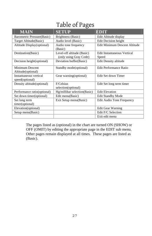
Table of Pages MAIN SETUP EDIT Barometric Pressure(Basic) Brightness (Basic) Edit Altitude display Target Altitude(Basic) Audio level (Basic) Edit Decision height Altitude Display(optional) Audio tone frequency
(Basic) Edit Minimum Descent Altitude
Destination(Basic) Level-off altitude (Basic) (only using Gray Code)
Edit Instantaneous Vertical Speed
Decision height(optional) Deviation buffer(Basic) Edit Density altitude
Minimum Descent Altitude(optional)
Standby mode(optional) Edit Performance Ratio
Instantaneous vertical speed(optional)
Gear warning(optional) Edit Set down Timer
Density altitude(optional) F/Celsius selection(optional)
Edit Set long term timer
Performance ratio(optional) Hg/millibar selection(Basic) Edit Elevation Set down timer(optional) Edit menu(Basic) Edit Standby Mode Set long term timer(optional)
Exit Setup menu(Basic) Edit Audio Tone Frequency
Elevation(optional) Edit Gear Warning Setup menu(Basic) Edit F/C Selection Exit edit menu
The pages listed as (optional) in the chart are turned ON (SHOW) or OFF (OMIT) by editing the appropriate page in the EDIT sub menu. Other pages remain displayed at all times. These pages are listed as (Basic).

28
Error messages There are only two error messages you will see in AMS 2000 operation. EN N-RDY This message is shown on the ALT page when the encoder is not sending valid altitude data. You will see this message while your encoder is warming up, or if it fails to operate. EN ERROR This message is shown on the ALT page when the AMS 2000 is receiving improper data. This message may indicate wiring problems or encoder malfunction, when AMS 2000 is connected to a conventional encoder. It may indicate encoder malfunction when connected to a Falcon Altitude Encoder. If you receive this error message, contact your avionics shop or installer to have your encoder and installation examined.

29
SPECIFICATIONS
PHYSICAL SPECIFICATIONS Size: 1.5” x 3.125” x 5.75”
Weight: 9 ounces Environmental Operating Temperature -10 Deg to +50 Deg C No cooling requirements Barometric Pressure Range 28.00” to 30.99” Electrical Power 10 to 28 VDC 300 mA max Protection Not internally fused Inputs Gray Code 11 pins - 10 signal, 1 return
(no diode isolation) Serial RS-232 Outputs Audio Out Variable frequency and amplitude Audio Switch Return, sink up to 2.0 ADC
Altitude Display Range -1000 feet to upper limit of encoder Resolution 100 feet (10 feet with serial Encoder) Regulatory: TSO-C88a RTCA/DO-160B C1CAPKSXXXXXXZBABZAA

30
Limited Warranty
Shadin Avionics warrants this instrument and system components to be free from defects in materials and workmanship for a period of one year from the user invoice date. Shadin will repair or replace any item under the terms of this Warranty, provided the item is returned to the factory prepaid. This obligation assumed by Shadin is limited to repair, replacement or refund of the product at the sole discretion of Shadin Avionics. This Warranty shall not apply to any product that has been repaired or altered by any person other than Shadin or that has been subjected to misuse, accident, incorrect wiring, negligence, improper or unprofessional assembly or improper installation by any person. This warranty does not cover any reimbursement for any person’s time for installation, removal, assembly or repair. Shadin retains the right to determine the reason or cause for warranty repair or replacement. This Warranty does not extend to any aircraft, vehicle, boat, machine or any other device to which this Shadin product may be installed, connected, attached, interconnected or used in conjunction with in any way. Shadin is not responsible for any shipping charges or damages incurred under this Warranty. No representative is authorized to assume any other liability for Shadin with the sale or resale of Shadin’s products. If you do not agree to and accept the terms of this Warranty, you may return the product in new condition, with receipt, within thirty (30) days for a refund. This warranty is made only to the original user. THIS WARRANTY IS IN LIEU OF ALL OTHER WARRANTIES OR OBLIGATIONS: EXPRESSED OR IMPLIED. SHADIN EXPRESSLY DISCLAIMS ALL IMPLIED WARRANTIES OF MERCHANTABILITY OR FITNESS FOR A PARTICULAR PURPOSE. PURCHASER AGREES THAT IN NO EVENT SHALL SHADIN BE LIABLE FOR SPECIAL, INCIDENTAL, OR CONSEQUENTIAL DAMAGES, INCLUDING LOST PROFITS OR LOSS OF USE OR OTHER ECONOMIC LOSS. EXCEPT AS EXPRESSLY PROVIDED HEREIN, SHADIN DISCLAIMS ALL OTHER LIABLITY TO PURCHASER OR ANY OTHER PERSON IN CONNECTION WITH THE USE OR PERFORMANCE OF SHADIN’S PRODUCTS, INCLUDING SPECIFICALLY LIABILITY IN TORT.


6831 Oxford Street
St. Louis Park, MN. 55426 USA
Sales: (800)-328-0584 Technical Support: (800)-388-2849
P/N OP8900A Rev F