altivar 58 telemecanique - steven...
TRANSCRIPT

Guide d'exploitationUser's manualBedienungsanleitungGuía de explotación
Altivar 58TelemecaniqueVariateurs de vitesse pourmoteurs asynchrones,Variable speed controllersfor asynchronous motors,Frequenzumrichterfür Drehstrom-Asynchronmotoren,Variadores de velocidadpara motores asíncronos.

1
Altivar 58
Variateur de vitesse pour moteurs asynchrones Page 2
Speed controller for asynchronous motors Page 24
Umrichter für Drehstrom-Asynchronmotoren Seite 46
Variador de velocidad para motores asíncronos Página 68
FR
AN
ÇA
ISE
NG
LIS
HD
EU
TS
CH
ES
PA
ÑO
L
24
EN
GL
ISH
NOTEThe speed controller is fitted with safety devices which, in the event of a fault, can shut down the speedcontroller and consequently the motor. The motor itself may be stopped by a mechanical blockage.Finally, voltage variations, especially line supply failures, can also cause shutdowns.
If the cause of the shutdown disappears, there is a risk of restarting which may endanger certainmachines or installations, especially those which must conform to safety regulations.
In this case the user must take precautions against the possibility of restarts, in particular by using alow speed detector to cut off power to the speed controller if the motor performs an unprogrammedshutdown.
The design of equipment must conform to the requirements of IEC standards.
In general, the speed controller power supply must be disconnected before any operation on either theelectrical or mechanical parts of the installation or machine.
The products and equipment described in this document may be changed or modified at any time,either from a technical point of view or in the way they are operated. Their description can in no waybe considered contractual.
ATTENTION
ATTENTION
IT NEUTRAL POINT CONNECTION : In the event of use on a 3-phase network with a voltage greaterthan 460V ±10 % with an isolated or high-impedance system (IT), the internal EMC filter capacitorswhich are connected to ground must be disconnected. Consult Schneider product support who are theonly people qualified to perform this operation.
When the speed controller is powered up, the power components and some of the control componentsare connected to the line supply. It is extremely dangerous to touch them. The speed controller covermust be kept closed.
After the ALTIVAR has been switched off and the green LED has gone out, wait for 3 minutes beforeworking on the equipment. This is the time required for the capacitors to discharge.
The motor can be stopped during operation by inhibiting start commands or the speed reference whilethe speed controller remains powered up. If personnel safety requires prevention of sudden restarts,this electronic locking system is not sufficient : fit a device to remove the power circuit.

25
EN
GL
ISH
Contents
Preliminary Recommendations ______________________________________________________ 26
Selecting a Speed Controller ________________________________________________________ 27
Available Torque __________________________________________________________________ 28
Technical Specifications ___________________________________________________________ 29
Dimensions - Mounting Recommendations ____________________________________________ 31
Presentation, General______________________________________________________________ 32
Access to Terminals _______________________________________________________________ 33
Power Terminals __________________________________________________________________ 34
Control Terminals _________________________________________________________________ 35
Fitting an Option Card _____________________________________________________________ 36
Connection Diagrams______________________________________________________________ 37
Electromagnetic Compatibility, Wiring ________________________________________________ 40
Wiring Recommendations - Use _____________________________________________________ 41
Setup ___________________________________________________________________________ 43
Operation - Maintenance - Spares and Repairs _________________________________________ 44
Warning
The Altivar 58 must be considered as a component : it is neither a machine nor a device ready for use in ac-cordance with European directives (machinery directive and electromagnetic compatibility directive). It is theresponsibility of the end user to ensure that the machine meets these standards.
The speed controller must be installed and set up in accordance with both international and nationalstandards. Bringing the device into conformity is the responsibility of the systems integrator who mustobserve the EMC directive among others within the European Union.
The specifications contained in this document must be applied in order to comply with the essential requi-rements of the EMC directive.
EN
GL
ISH
Preliminary Recommendations
Delivery
Check that the speed controller reference printed on the label is the same as that on the delivery notecorresponding to the purchase order.
Remove the Altivar 58 from its packaging and check that it has not been damaged in transit.
Handling and storage
To ensure the speed controller is protected before installation, handle and store the device in its packaging.
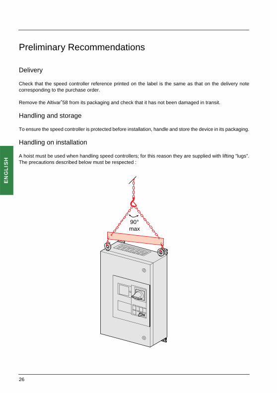
Handling on installation
A hoist must be used when handling speed controllers; for this reason they are supplied with lifting "lugs”.The precautions described below must be respected :
90°max90°max
26

EN
GL
ISH
Selecting a Speed Controller
High torque applications(170% Tn)3-phase supply voltage (1) : 380…500 V 50/60 Hz
Standard torque applications (120% Tn)3-phase supply voltage (1) : 380…500 V 50/60 Hz
(1) Nominal supply voltages : min. U1 (380 V), max. U2 (500 V).
(2) Typical value for a 4-pole motor.
(3) These power ratings are for a maximum switching frequency of 2 to 4 kHz, depending on the size, andcontinuous operation. Switching frequencies are detailed in the section on "Technical Specifications".Using the ATV-58 with a higher switching frequency :
• For continuous operation derate b
y one power rating, for example : with high torque applications :ATV-58ED23N4 for 11 kW – ATV-58ED79N4 for 45 kW.
• If no power derating is applied, do not exceed the following operating conditions :Cumulative running time 36 s maximum per 60 s cycle (load factor 60 %).
(4) For 60 seconds.
(5) Speed controllers ordered under references ATV-58EiiiN4 are supplied with a display module.Speed controllers ordered under the same references ending in Z (ATV-58EiiiN4Z) are suppliedwithout a display module.
The additional letter Z only appears on the packaging.
Motor Line supply Altivar 58 Reference (5) Weight
Power indicated on plate (3)
Line current (2)
Max prospective line Isc
Nominal current
Max transient current (4)at U 1 at U 2 at U 1 at U 2
kW HP A A kA kA A A kg
7.5 10 17.5 14 22 22 17.6 24 ATV-58ED12N4 43
11 15 24 20 22 22 24.2 32.9 ATV-58ED16N4 43
15 20 29.5 25.5 22 22 33 44.9 ATV-58ED23N4 46
18.5 25 43 35 22 65 41 55 ATV-58ED28N4 70
22 30 51 41 22 65 48 66 ATV-58ED33N4 70
30 40 68 55 22 65 66 90 ATV-58ED46N4 70
37 50 82 66 22 65 79 108 ATV-58ED54N4 110
45 60 101 82 22 65 94 127 ATV-58ED64N4 110
55 75 121 98 22 65 116 157 ATV-58ED79N4 110
22 30 51 41 22 65 44 55 ATV-58ED28N4 70
30 40 67 53 22 65 60 66 ATV-58ED33N4 70
37 50 82 66 22 65 72 90 ATV-58ED46N4 70
45 60 99 79 22 65 85 108 ATV-58ED54N4 110
55 75 121 97 22 65 105 127 ATV-58ED64N4 110
75 100 160 130 22 65 138 157 ATV-58ED79N4 110
27

EN
GL
ISH
Available Torque
Torque characteristics :
1 Self-cooled motor : continuous useful torque2 Force-cooled motor : continuous useful torque3 Transient overtorque for max. 60 seconds.4 Torque at overspeed with constant power
Available overtorque :
• High torque applications :200 % of nominal motor torque for 2 seconds, and 170 % for 60 seconds.
• Standard torque applications :140 % of nominal motor torque for 2 seconds, and 120 % for 60 seconds.
Continuous operation
For self-cooled motors, cooling is linked to the motor speed. Derating therefore occurs at speeds of less than half the nominal speed.
Overspeed operation
As the voltage can no longer change with the frequency, there is a reduction in torque. Check with themanufacturer that the motor can operate at overspeed.
Note : With a special motor the nominal and maximum frequencies can be adjusted from 40 to 500 Hzusing the operator display module, the programming terminal or the PC software.
• High torque applications : • Standard torque applications :
0 N (Hz)
0.5
2530
5060
1
3
2 2
1
1
10.95
1.5
1.701.75T/Tn
1.25
7590
100120
4
0 N (Hz)
0.5
2530
5060
1
3
2 2
1
1
10.95
1.5
1.701.75T/Tn
1.251.20
7590
100120
4
28

EN
GL
ISH
Technical Specifications
Environment
Degree of protection IP 55
Vibration resistance Conforming to IEC 68-2-6 :• 1.5 mm peak from 2 to 13 Hz• 1 gn from 13 to 200 Hz.
Shock resistance Conforming to IEC 68-2-27 :• 10 gn, 11 ms
Maximum ambient pollution ATV-58ED28N4 to D79N4 :• Degree 3 conforming to UL508C.ATV-58ED12N4 to D23N4 :• Degree 2 conforming to IEC 664-1 and EN 50718.
Maximum relative humidity 93 % without condensation or dripping water conforming to IEC 68-2-3Ambient temperaturearound the unit
Storage :• - 25 °C to + 65 °C
Operation :• -10 °C to + 40 °C
Maximum operating altitude 1000 m without derating (above this derate the current by 1 % for each additional 100 m)
Operating position Vertical
29
EN
GL
ISH
Technical Specifications
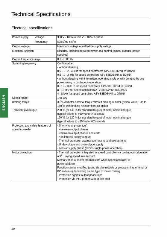
Electrical specifications
Power supply Voltage 380 V - 10 % to 500 V + 10 % 3-phase
Frequency 50/60 Hz ± 5 %
Output voltage Maximum voltage equal to line supply voltage
Electrical isolation Electrical isolation between power and control (inputs, outputs, power supplies)
Output frequency range 0.1 to 500 HzSwitching frequency Configurable :
• without derating :0.5 - 1 - 2 - 4 kHz for speed controllers ATV-58ED12N4 to D46N40.5 - 1 - 2 kHz for speed controllers ATV-58ED54N4 to D79N4• without derating with intermittent operating cycle or with derating by one power rating in continuous operation :8 - 12 - 16 kHz for speed controllers ATV-58ED12N4 to D23N48 - 12 kHz for speed controllers ATV-58ED28N4 to D46N44 - 8 kHz for speed controllers ATV-58ED54N4 to D79N4
Speed range 1 to 100Braking torque 30 % of motor nominal torque without braking resistor (typical value). Up to
150 % with braking resistor fitted as optionTransient overtorque 200 % (or 140 % for standard torque) of motor nominal torque
(typical values to ±10 %) for 2 seconds170 % (or 120 % for standard torque) of motor nominal torque(typical values to ±10 %) for 60 seconds
Protection and safety features of speed controller
- Short-circuit protection : • between output phases • between output phases and earth • on internal supply outputs- Thermal protection against overheating and overcurrents- Undervoltage and overvoltage supply- Loss of supply phase (avoids single-phase operation)
Motor protection - Thermal protection integrated in speed controller via continuous calculation of I2T taking speed into accountMemorization of motor thermal state when speed controller ispowered downFunction can be modified (using display module or programming terminal or PC software) depending on the type of motor cooling- Protection against output phase loss- Protection via PTC probes with option card
30

EN
GL
ISH
Dimensions - Mounting Recommendations
Dimensions(in mm)
Mounting brackets can be used vertically or horizontally.
Mounting recommendations
ATV-58E a b c G1 G2 H1 H2 Ø
D12N4, D16N4, D23N4 500 700 300.5 437.5 550 637.5 750 9
D28N4, D33N4, D46N4 460 850 365.5 397.5 510 787.5 900 9
D54N4, D64N4, D79N4 570 1050 405.5 507.5 620 987.5 1100 9
8xØ
b H2
H1
c 10 G1
a
G2
500
500
Do not place the unit close to heating elements.Leave sufficient free space to ensure that the air required forcooling purposes can circulate from the bottom to the top ofthe unit.
31

EN
GL
ISH
Presentation, General
1 - Triangular key lock. Can only be opened when switch 2 is in the OFF position.2 - Access flap to the display module.3 - Control handle for switch. Do not turn to ON position when the door is open.4 - Pushbutton mounting plate containing :
• 3-position switch : Stop and the 2 operating directions (FW, RV). The speed controller is supplied withonly 1 direction (FW) wired.• Speed reference potentiometer.• Slots available for the addition of control or signalling units.
5 - Blanking plate for cable grommets if communication buses are used (See catalogue).6 - Gland plate for customer cable glands.
ATV-58ED12N4 to D23N4
ATV-58ED28N4 to D79N4
1
2
3
4
1
5
6
1
2
3
4
1
6
5
32

EN
GL
ISH
Access to Terminals
Access to terminals
Before working on the unit, switch off the power supply upstream of the ATV58E••• and wait 3 minutes forthe capacitors to discharge.Set the switch to OFF before opening the compartment door.
ATV-58ED12N4 to D23N4
ATV-58ED28N4 to D79N4
Line supply connected directly to the switch
Space available for addition of a contactor
Line supply connected directly to the switch
Space available for addition of a contactor
33
EN
GL
ISH
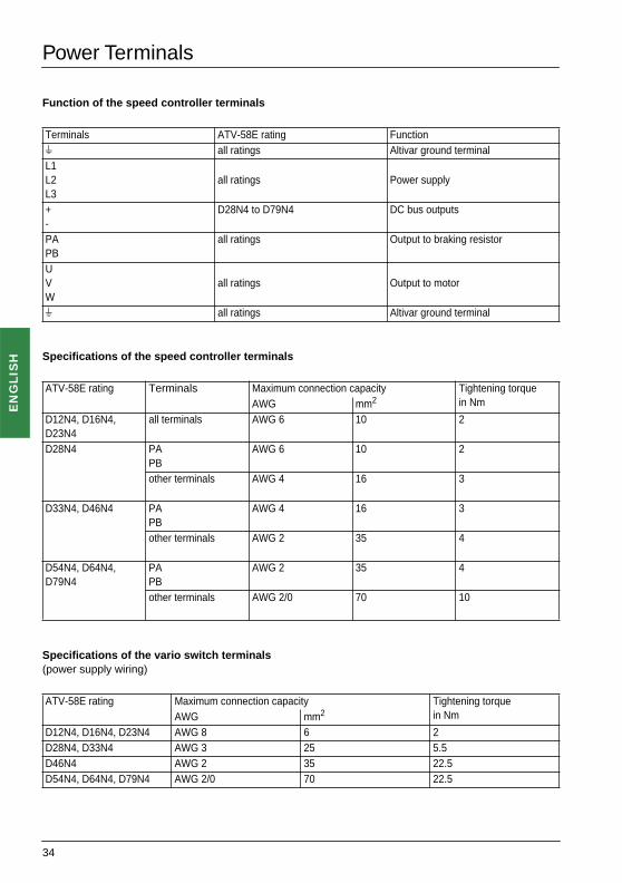
Power Terminals
Function of the speed controller terminals
Specifications of the speed controller terminals
Specifications of the vario switch terminals (power supply wiring)
Terminals ATV-58E rating Functions all ratings Altivar ground terminal L1L2L3
all ratings Power supply
+-
D28N4 to D79N4 DC bus outputs
PAPB
all ratings Output to braking resistor
UVW
all ratings Output to motor
s all ratings Altivar ground terminal
ATV-58E rating Terminals Maximum connection capacity Tightening torque in NmAWG mm2
D12N4, D16N4, D23N4
all terminals AWG 6 10 2
D28N4 PAPB
AWG 6 10 2
other terminals AWG 4 16 3
D33N4, D46N4 PAPB
AWG 4 16 3
other terminals AWG 2 35 4
D54N4, D64N4, D79N4
PAPB
AWG 2 35 4
other terminals AWG 2/0 70 10
ATV-58E rating Maximum connection capacity Tightening torque in NmAWG mm2
D12N4, D16N4, D23N4 AWG 8 6 2D28N4, D33N4 AWG 3 25 5.5D46N4 AWG 2 35 22.5D54N4, D64N4, D79N4 AWG 2/0 70 22.5
34

EN
GL
ISH
Control Terminals
Speed controller terminal characteristics
- Connection terminal for shielding : for metal connector or clamp - 2 removable terminals, one for relay contacts, the other for low level I/O- Maximum connection capacity : 1.5 mm2 - AWG 14- Max. tightening torque : 0.4 Nm.
Arrangement of speed controller terminals
Function of speed controller terminals
Terminal Function Electrical characteristics
R1AR1BR1C
C/O contact at common point (R1C) of R1 fault relay
Min. switching capacity :• 10 mA for 24 VaMax. switching capacity on inductive load(cos ϕ 0.4 and L/R 7 ms) :• 1.5 A for 250 Vc and 30 Va
R2AR2C
N/O contact of R2 programmable relay
s Connection for cable shieldingCOM Common for logic and analog inputsAI1 Analog input for voltage Analog input 0 + 10 V impedance 30 kΩ+10 Power supply for potentiometer with
setpoint 1 to 10 kΩ+10 V ± 1 % 10 mA max. protected against short-circuits and overloads
AI2 Analog input for current Analog input X - Y mA, X and Y are programmableFactory preset to 4 - 20 mAimpedance 100 Ω
LI1LI2LI3LI4
Logic inputs Programmable logic inputsimpedance 3.5 kΩPower supply + 24 V (max. 30 V)State 0 if < 5 V, state 1 if > 11 V
+ 24 Power supply for inputs + 24 V protected against short-circuits and overloads, min. 18 V, max. 30 VMax. flow rate 200 mA
R1A
R1B
R1C
R2A
R2C s CO
M
AI 1
+ 1
0
AI 2
LI 1
LI 2
LI 3
LI 4
+ 2
4
Control card
35

EN
GL
ISH
Fitting an Option Card
The ATV58E will accept one of the option cards offered in the catalogue :• Either an I/O extension card.• Or a customer-specific card.• Or a communication card.
Fitting a card
The card should be fitted before installing and wiring the ATV-58E.Make sure that the speed controller is switched off, open the switch using its external front handle,disconnect the upstream power supply and wait 3 minutes for the capacitors to discharge.
Plug the option card connector into the control card connector as shown below, then fix it with 3 screws.
36

EN
GL
ISH
Connection Diagrams
The shaded areas are to be wired by the user.To find the rating of a line contactor or a possible downstream contactor, refer to the Altivar 58 catalogue.
Basic diagram :
Braking resistor if fitted
Note : The 3-position switch is factory wired for a single operating direction. The contact for the 2ndoperating direction is available to be wired if necessary.
U V
R1C
R1B
R1ALI
4
LI3
LI2
AI2
s
s
U1
W1
V1
M 3 c
W R2C
R2A +24
LI1
CO
M
AI1 +10
PA
PB
s
Fw 13
14
0 2324
L2L1 L33
A1
37

EN
GL
ISH
Connection Diagrams
Adding a line contactor
First disconnect the wires to terminals L1, L2, L3 and connect them to the contactor, so as to reconnect thewiring with its ferrite cores if present. Then add wires between the contactor and terminals L1, L2, L3.
Adding a downstream contactor for ATV-58ED12N4 to D23N4
Use the "downstream contactor control" function with relay R2, or logic output LO (a 24 V) with an I/Oextension card. Consult the programming manual.
Note : Fit interference suppressors to all inductive circuits near the speed controller or connected on thesame circuit, such as relays, contactors, solenoid valves, fluorescent lighting, etc.
L1 L2 L3A1
– KM1
21
43
65
– KM1A2A1– S1– S2
13R1CR1A 14– KM1
– T1– Q21 2 – Q31 2
3 4 – Q25 6
A1
3 c
U V W
U1
W1
V1
M 3 c
A1
A2
A1
R2C
– KM2
12
34
56
R2ACO
M(0
V)
+24
38
EN
GL
ISH
Connection Diagrams
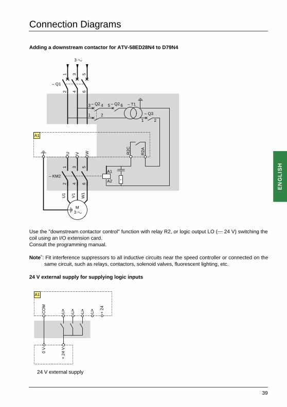
Adding a downstream contactor for ATV-58ED28N4 to D79N4
Use the "downstream contactor control" function with relay R2, or logic output LO (a 24 V) switching thecoil using an I/O extension card. Consult the programming manual.
Note : Fit interference suppressors to all inductive circuits near the speed controller or connected on thesame circuit, such as relays, contactors, solenoid valves, fluorescent lighting, etc.
24 V external supply for supplying logic inputs
24 V external supply
U V W
U1
W1
V1
M 3 c
A1
A1
A2
R2C
– KM2
12
34
56
R2A
– Q1
12
34
56
– T1– Q23 4
– Q3
1 21 2
– Q25 6
3 cLI
•
LI•
LI•
LI•
+ 2
4
CO
M0
V
+ 2
4 V
A1
39

EN
GL
ISH
Electromagnetic Compatibility, Wiring
Principle
• Grounds between speed controller, motor and cable shielding must have "high frequency"equipotentiality.
• Use shielded cables with shielding connected to the ground at 360° at both ends of the motor cable,braking resistor (if fitted) and control-command cables. Conduit or metal ducting can be used for part ofthe shielding length provided that there is no break in continuity.
• Ensure maximum separation between the power supply cable (line supply) and the motor cable.
ATV58-ED12N4 to D23N4
ATV58-ED28N4 to D79N4
1: Line supply cable to be connected to the vario switch (3 phases + PE)
2: Shielded motor cable to be connected tothe speed controller (3 phases + PE)
3: Metal clamp for grounding the motor cable shielding
1
2
3
1: 3 phases of the line supply cable to be connected to the vario switch.
2: PE conductor for the line supply cable to beconnected directly to the speed controller,passing through the ferrite core ➂
3: Factory-fitted ferrite core
4: Shielded motor cable to be connected tothe speed controller (3 phases + PE)
5: Metal clamp for grounding the motor cable shielding
1
2
3
4
5
40

EN
GL
ISH
Wiring Recommendations - Use
Wiring recommendations
Power
Observe the cable cross-sectional areas recommended in the standards.
The speed controller must be earthed to conform with the regulations concerning high leakage currents(over 3.5 mA). Do not use a residual current device for upstream protection on account of the DC elementswhich may be generated by leakage currents. If the installation involves several speed controllers on thesame line, each speed controller must be earthed separately.
Keep the power cables separate from circuits in the installation with low-level signals (detectors, PLCs,measuring apparatus, video, telephone).
Control
Keep the control circuits and the power cables apart. For control and speed reference circuits, werecommend using shielded twisted cables with a pitch of between 25 and 50 mm, connecting the shieldingto each end.
Recommendations for use
In power control mode using a line contactor :
- Do not switch contactor KM1 frequently (otherwise premature aging of the filtering capacitors will occur) and use inputs LI1 to LI4 to control the speed controller.
- If the cycles are shorter than 60 s these measures are absolutely necessary.
If safety standards necessitate isolation of the motor, fit a contactor on the speed controller output and usethe "downstream contactor control" function (see programming manuall).
Fault relay, unlocking
The fault relay is energized when the speed controller is powered up and is not faulty. It has one C/Ocontact at the common point.
The speed controller is unlocked after a fault by one of the following methods :
- power down the speed controller until both the display and indicator lamps go out, then power up again- automatically or remotely via logic input : consult the programming manual.
Programmable I/O, functions :
Consult the programming manual.
41

EN
GL
ISH
Use
Use
The ATV58E speed controller is supplied with standard configuration and factory settings (seeprogramming manual) :• Macro-configuration : Handling.• Only one operating direction wired.
It is wired and configured to restart automatically after any fault shutdown has been resolved,for example when the power supply has been cut and then reconnected.Make sure that operation is compatible with the application safety conditions. If not, the wiringand configuration must be modified.
To use the available inputs and outputs, the wiring must be completed as required. Refer to the programming manual for any reconfiguration of these inputs/outputs.
42

EN
GL
ISH
Setup
The Altivar is factory preset for the most common operating conditions.
Prior to powering up the Altivar :
Unlock and tilt the transparent cover 1 of the Altivar to open it or open the compartment door in orderto access the 50/60 Hz selector switch on the control card.If an option card is present, the selector switch can still be accessed through it.Set the selector switch to the 50 or 60 Hz position, whichever corresponds to your motor, using anappropriately-sized screwdriver.
Preset operating point :50 Hz position (factory setting) : 400 V 50 Hz60 Hz position : 460 V 60 Hz
Several tools are available to help with setup :- display module ref : VW3 A58101 (the speed controller is supplied with or without
this display module, according to the reference ordered).- programming terminal ref : VW3 A58102L1 (English/French/Spanish) or VW3 A58102L2
(English/German/Italian) to be ordered separately.- PC software and interface ref : VW3 A58104 to be ordered separately.
Refer to the documentation provided with each of the tools for information on setup and maintenance ofthe Altivar.
If your Altivar is equipped with an I/O extension or communication card, consult the documentation suppliedwith the card.
Reminder for IT neutral point connection : in the event of use on a 3-phase network with a voltage greaterthan 460V ±10% with an isolated or high-impedance neutral system (IT), the internal EMC filter capacitorswhich are connected to ground must be disconnected. Consult Schneider product support who are the onlypeople qualified to perform this operation.
xv50 Hz 60 Hz
1
43

EN
GL
ISH
Operation - Maintenance - Spares and Repairs
Operation
Signalling on the front panel of the Altivar
Display mode on display module screen
Displays preset frequency setpoint, or faults.The display mode can be modified via the display module : consult the programming manual.
Maintenance
Before working on the equipment, switch off the power supply and wait for the capacitors to discharge (approximately 3 minutes).
The DC voltage at the + and - terminals or PA and PB terminals may reach 850 V depending on the line supply voltage.
If problems arise during setup or operation, first ensure that the recommendations relating to environment,mounting and connections have been observed.
Maintenance
The Altivar 58 does not require preventative maintenance. We nevertheless advise you regularly to :- Check the condition and tightness of connections- Ensure that the temperature around the unit remains at an acceptable level and that ventilation is effective(average service life of fans : 3 to 5 years depending on operating conditions)
- Remove dust from the speed controller if necessary
Assistance with maintenance
The first fault detected is memorized and displayed on the display module screen if power is maintained :the speed controller locks, the red LED lights up, the R1 fault relay and any contactors which may be pre-sent are activated.Consult the programming manual.
Spares and repairsFor spare parts and repairs to Altivar 58 speed controllers, consult Schneider group product support.
Green POWER LED
Red FAULT LED
on : Altivar powered up
• on : Altivar faulty• flashing : Altivar locked following use of the "STOP" button on the display module or a configuration change. The motor must not be powered up until the "forward", "reverse" and "shutdown via injection" commands have been reset.
FAULT
POWER z
44

VVDED399042
21384
W9 1624159 01 12 A02
1999-08