aluminium primary production off-gas composition and
TRANSCRIPT

ALUMINUM: RECYCLING AND ENVIRONMENTAL FOOTPRINT
Aluminium Primary Production Off-Gas Compositionand Emissions: An Overview
THOR ANDERS AARHAUG 1,2 and ARNE PETTER RATVIK1
1.—SINTEF Industry, Trondheim, Norway. 2.—e-mail: [email protected]
The raw gas composition from primary aluminium production depends mostlyon the process technology applied and the composition of the raw materials. Atsteady state, a stationary condition is established among the material sources,gas production and sinks: the gas treatment centre and escaping gases. Only afew papers discuss the off-gas composition itself; most papers deal with the gascomposition from laboratory-scale experiments performed under inert condi-tions. In this article, an overview of the literature describing gas productionfrom aluminium electrolysis is given. Effects of temperature and chemicalequilibrium on the stationary condition are also discussed. The typicalchemical composition of the raw materials is presented to evaluate their inputinto the gas composition, especially with respect to their impurity levels.
PROCESS OVERVIEW
The Smelting Process
Aluminium (Al) is produced by electrochemicalreduction of alumina (Al2O3) dissolved at about950�C in a molten salt based on cryolite (Na3AlF6)with aluminium fluoride (AlF3) and calcium fluoride(CaF2) to reach an NaF (sodium fluoride) to AlF3
molar ratio of about 2.2. Direct current (DC) isprovided as the energy required by the reductionreaction as well as maintaining the cryolite bathtemperature through resistive heating and compen-sate for heat losses. Carbon (C) anodes are con-sumed by the anode reaction as a reducing agent,forming mainly carbon dioxide (CO2) besides somecarbon monoxide (CO). Graphite is most commonlyused as current conductor to the cathode in modernelectrolysis cells (the graphite is commonly denotedas the cathode although, in principle, the alu-minium pad on top of the graphite is the cathode).The net reaction is:
1
2Al2O3 sð Þ þ 3
4C sð Þ ¼ Al lð Þ þ 3
4CO2 gð Þ ð1Þ
The produced metal has a higher density than theelectrolyte and is regularly tapped (siphoned) fromthe aluminium pad over the bottom of the cell. Theanodes are covered by anode cover material (ACM)
to minimise the heat loss from the process as well asprevent air and CO2 burns of the anodes, whichincrease the carbon consumption.
Whereas open electrolysis cells were historicallyused, modern technology makes use of a super-structure to contain the gases and dust producedduring smelting. Large fans are used to extractthese gases along with air from the draught, thedraught serving to cool the off-gas as well as thesuperstructure.
Gas Treatment Centre
Due to the negative environmental impact offluoride and sulfur emissions, the off-gases aretreated before being emitted to the environment.In the early 1970s, scrubbing technology, makinguse of primary alumina to clean the off-gas, wasestablished. By exposing the off-gas to alumina andretaining fine particulates using bag filters, emis-sions were drastically reduced. The alumina (sec-ondary alumina) from the gas treatment centre(GTC) is then fed to the reduction cells.
The scrubbing efficiency is dependent on manyfactors, but normal operation of the GTC allows forscrubbing efficiencies> 99% in the case of hydro-gen fluoride (HF) and fluoride particulates. Thehigh efficiency in recovery of fluorides also has aneconomic impact, as less AlF3 must be added tomaintain the NaF/AlF3 bath ratio.
JOM, Vol. 71, No. 9, 2019
https://doi.org/10.1007/s11837-019-03370-6� 2019 The Author(s)
2966 (Published online February 19, 2019)

The scrubbing efficiency for other gas speciesthan HF is less efficient. Permanent gases, such asCO, CO2 and PFCs, pass readily through the filter.Sulfurous gases such as COS and SO2 are partiallyretained by the scrubber and returned to the cells.In the case of SO2, the limiting scrubbing efficiencyis a result of the competition with the strongeradsorbing HF over SO2 on alumina.1 As the off-gasis the only sink for sulfur, all sulfur eventually endsup as emissions.
Where legislation restricts SO2 emissions, the dryscrubber is accompanied by a wet scrubber. The wetscrubber makes use of either seawater or a causticsolution to capture SO2 as sulphate.
Impurity Cycling
Whereas the introduction of off-gas scrubbing ledto a positive environmental effect as well asimproved economics, there are also some negativeeffects. By introducing filters, virtually all particu-late matter is trapped and returned to the processwith the secondary alumina. Impurities trapped inthe gas treatment centre will therefore accumulatein the process unless they are provided anothersink. Fugitive emissions from the potroom, result-ing from incomplete evacuation of the off-gases fromthe superstructure and open lids during anodechanges, are now the major emission routes forgases and particulates otherwise captured by thedry scrubber. Management measures to reducefluoride emissions in plants have been proposed.2
The other major sink is the produced aluminiummetal. The interaction among the smelting process,gas cleaning and emissions is illustrated in Fig. 1.
One example of an impurity with a negativeimpact is phosphorous. Phosphorous has severaloxidation numbers and thus negatively affects thecurrent efficiency of the process. Phosphorous haslow metal solubility and few gaseous species. Other
examples include metals, where metals more noblethan aluminium mostly report to the metal whereasless noble metals predominate in the electrolyte.Often a ratio of 10:1 between the metal and bath isreported for the more noble impurities, while areverse ratio of 1:10 is reported for the less nobleimpurities.
The Fluoride Cycle
Fluoride is an essential part of the process assufficient alumina dissolution is only possible influoride-based molten salt systems. The major lossesof fluorides are due to fugitive emissions in the formof particulates and free or adsorbed gases. The GTCeffectively captures> 99% of the fluorides in theraw gas and reintroduces the fluorides to theelectrolysis bath. At operating temperature, NaAlF4
(sodium tetrafluoroaluminate) is the main fluoridecompound evaporating from the molten electrolyte.The off-gas temperature drops rapidly as it entersthe superstructure and meets the draught, causingthe metastable NaAlF4 to be quenched. In addition,NaAlF4 disproportionates to form chiolite(Na5Al3F14) and AlF3. As the off-gas reaches theGTC, HF is the only gaseous fluoride species apartfrom minor amounts of perfluorocarbon speciesformed during anode effects or in alumina-depletedspots under the anodes.
The Sulfur Cycle
Sulfur is introduced to the process mainly as animpurity in the anode carbon. Carbonyl sulphide(COS) is the main sulfur gas species formed duringthe oxidation of sulfur bound with carbon. COSreacts with oxygen in the air to form sulfur dioxide(SO2), which is the major sulfurous gas speciesfound in the off-gas reaching the GTC. Not manydata have been published on retaining sulfur in theGTC, but both SO2 and COS exhibit a significant
Fig. 1. Schematic of the material flow among the smelting process, gas treatment centre and emissions.
Aluminium Primary Production Off-Gas Composition and Emissions: An Overview 2967

concentration difference over the GTC. Theobserved reduction in COS may be caused bycatalytic hydrolysis in contact with alumina in theGTC.3 Secondary alumina with adsorbed sulfurgases and sulphates is returned to the electrolysisbath.4–6 Upon dissolution of alumina, most of thesulfur is rapidly re-released to the gas phase,although mechanisms have been reported for sul-phite and sulphate formation.7 The short residencetime in the cell increases the gas release from thebath and potentially entrainment of bath com-pounds and particulates. Due to the lower GTCscrubbing efficiency for sulfur, gas emission fromthe GTC are the major contributor to sulfur emis-sions unless a wet scrubber is installed.
Off-Gas Composition
Very little information has been publishedregarding the full composition of the off-gas fromprimary aluminium production. A major obstacle tocharacterization is the detrimental effect of HF tomulticomponent gas analysers. Therefore, mostcharacterization has been performed downstreamthe GTC.
Whereas quite a few gas constituents are knownto pass unhindered through the GTC (e.g., CO2, CO,PFC, N2), others show various degrees of retention(e.g., HF, SO2, COS). The retention will vary withtechnology, raw gas temperature and humidity andtherefore makes projection of off-gas compositionfrom the cleaned gas side difficult.
The variations in dilution by draught under thecell hoods are one contributor to variations in theoff-gas concentrations. The main constituents of air(N2, O2, Ar, H2O) co-vary and dilute the processgases. However, several mechanisms may affect thisratio, such as CO burn and oxidation of COS.Nevertheless, a generalization of the compositionhas been attempted in Table I, based on unpub-lished results from the authors. Some reasons forthe drop in SO2 across the GTC are believed to becaused by adsorption of SO2 on alumina as well aspartial conversion to sulphate or SO4
2� or operationof the scrubber at an elevated new ore feed rate.
Characterizations of dust loading and fluorideand sulfur content are performed by the smelters ona regular basis. Typical dust loads in the ducts have
been reported in the range of 0.3 g dust per kgexhaust gas by Fleer.8 For the reported exhaust flowof 6100 Nm3/h per cell (190 kA cells), consideringvariations in the suction and size of cells betweendifferent plants, it is reasonable to assume that theparticulate load is in the range of 1–3 kg/h per cell(1 Nm3/h = 1.295 kg/h), depending on the suctionrate and particle size distribution of the secondaryalumina. Based on analyses of the impurities in theoff-gas and secondary alumina,9 it is shown that thefiner fractions consist mainly of condensed bathparticles whereas the impurities are generallyfound in the lower micron size fractions togetherwith the secondary alumina fines.
Technology Prospects
The ultimate goal of industrial production ofprimary aluminium is zero emissions, no environ-mental impact and no waste of energy or materials.Despite significant improvements in these issuesover the last decades, the industry is expected toface even stricter regulations in the future. Toanswer this challenge, both new operation stan-dards and improved systems will be required.
Exact knowledge of fundamental process mecha-nisms is a prerequisite to push the limits, requiringdedicated research and innovations and willingnessto pursue new ideas, especially for waste andemissions not readily handled with today’s technol-ogy. This article gives an overview of the existingknowledge and presents future challenges.
Environmental Aspect
Over the years, the aluminium industry hasmanaged to reduce emissions from the productionsteps to a significant degree. The most noticeableprogress was obtained by the introduction of dryscrubbers as most of the particulates and fluoridesin the off-gas emissions are captured by dry scrub-bers. Since most of the sulfur gases pass through thedry scrubber, many plants are still emitting signif-icant amounts of sulfur dioxide (SO2) and carbonylsulfide (COS) to the atmosphere. In countries withstricter regulations on sulfur emissions, wet scrub-ber systems are implemented. Seawater scrubbingis the preferred method for plants located at thecoast, while caustic solutions are used elsewhere. Ifthe electrolyte is depleted in alumina, potent green-house perfluorocarbon (PFC) gases are formed.Although the decrease in the number of anodeeffects has reduced the formation and release ofPFCs, the high greenhouse gas (GHG) potential inthe range of 5000–10,000 in a 100-year perspectivecan cause even small emissions to contribute to theglobal warming.
As anodes are replaced every 3–4 weeks, furnacecovers must be removed regularly. Due to the heatflux and the transport of anodes in open air, diffuseemissions are significant, from both the removedanodes and the pot with open covers, including the
Table I. Generalized gas composition relative toCO. Sulfur losses have not been quantified in theliterature but are indicated in the table with a<
Gas Raw gas After GTC
CO 1 1CO2 10 10HF 0.07 0.001SO2 0.1 < 0.1COS 0.01 < 0.01
Aarhaug and Ratvik2968

emissions during crust cleaning of the anode cavitybefore setting new anodes. The distribution ofparticulates from different pot sources, such asalumina, cover material and bath fumes, collectedat different sites in aluminium plants have beenreported.10 To reduce the emissions, some plantsuse booster suction during anode change and/orplace pulled anodes in designated collecting systemswith hooding during cooling.
Product Quality
Many of today’s emissions are a consequence ofthe raw materials, e.g., impurities in the alumina(Al2O3) and aluminium fluoride (AlF3) feed, andheavy metals and sulfur present in the carbonanodes. Other emissions are a consequence of theprocess, e.g., fluoride emissions, or secondary reac-tions taking place inside the cell or in the gas duct.With efficient dry scrubbing, using the smeltergrade alumina (SGA) as fluoride adsorbent beforefeeding the alumina to the cells, most raw gaselements in the form of particulates are returned tothe cells, eventually leaving the metal and to someextent surplus electrolyte as the major sink forimpurities.
Presently, there are no indications that the rawmaterials will be of higher purity in the future.Especially the trend within coke for carbon anodesis negative, as the availability of good quality cokesis not expected to increase at the same rate as thealuminium production. This will force the anodemanufacturers and aluminium producers to acceptlower quality cokes with higher impurity levels.Also, the increased production of sour oil adds tothis picture, while the recent growth in shale oil,which contains few of the heavier fractions that endup as anode coke. Considering that the currentgrowth in consumption of fossil fuels is not sustain-able, the future availability may be even worse. Thismay require additional actions at the plants tohandle or remove impurities.
Energy Recovery
Today’s most energy-efficient cells of operate at13–14 kWh/kg, which is about twice the theoreticalenergy required to produce aluminium.11 About halfof the energy input is dissipated as heat, mostly tothe cell hooding (superstructure) where the currentpractice is to cool the off-gas by allowing a draughtto enter the cell. As a consequence, the off-gassystem has to pull about 100 times the gas amountproduced in the cell reaction. Since the power usedby the fans to manage good off-gas suction, and theenergy input to the anode production is not reportedin the kWh/kg aluminium, the total energy con-sumption considering the whole plant operation ishigher. In the future, it is expected that producerswill reduce the draught and install heat exchangersin the off-gas system, opening up for heat recoveryand/or power production as well as carbon dioxide
(CO2) capture. Some minor efforts have started,mostly looking at heat exchangers motivated byreducing the off-gas temperature to improve the dryscrubbing.12–14
IMPURITY SOURCES
Impurities in Aluminium Production
Understanding and controlling emissions fromthe cells are important, both due to environmentalregulations and as basis for counteractive actionsfrom lower quality raw materials causing higheremissions. It is uncertain if the rapid growth in theglobal aluminium production will increase theimpurity level of raw materials, but it is likely thatit will not decrease. Focus here will be on the mostsignificant impurities in the emissions, those withimpact upon the work environment and/or sur-rounding areas.
The two main sources for impurities in alu-minium production are from the alumina andcarbon anodes. In addition, aluminium fluorideand contamination from production equipment con-tribute. Some non-metallic elements form gaseousspecies, which may or may not be captured in thegas treatment centre (GTC). Evaporation from thebath and bath entrainment with the off-gas are theother main sources for emissions. Most of thecaptured impurity elements in the GTC will accu-mulate in the bath and eventually end up in themetal or surplus bath. In addition, polyvalentimpurities may contribute to some loss in currentefficiency.
Anodes
The main emission from aluminium production isCO2 from the consumption of the carbon anodes. Ifthe contribution from sulfur in the anodes isomitted, the theoretical carbon consumption is333.3 kg per tonne of Al produced, equivalent to1222.2 kg of CO2 per tonne Al. In reality, the carbonconsumption exceeds 400 kg because of secondaryreactions, i.e., air burn (poor coverage of anodes)and the Boudouard reaction (CO2 burn), resulting inCO2 emissions closer to 1500 kg/tonne Al.
All cokes used in the production of anodes foraluminium electrolysis contain sulfur. A certaincontent of sulfur in anode cokes is consideredbeneficial for the anode performance, based onbetter results in the ISO 12981-1:2000 CO2 reactiv-ity test (CO2 burn), resulting in most anodes beingproduced with a sulfur content between 1.5 wt.%and 2 wt.% sulfur, equivalent to 12–16 kg SO2
released per tonne of aluminium produced. Differ-ent cokes are usually blended to obtain the desiredsulfur content. The forecast for anode cokes of goodquality to meet the growth in the aluminiumindustry is, however, bleak, so this sulfur contentmay increase.
Aluminium Primary Production Off-Gas Composition and Emissions: An Overview 2969

As most impurities in anode cokes correlate withsulfur, other impurities are also expected toincrease unless the coke precursors are purifiedand/or desulfurized prior to coking (e.g., see Lind-say15). Sulfur is mainly released from the anodes asCOS, which rapidly reacts to SO2 in contact withair. Impurities are also introduced to the anodesthrough recycled butts. These are mainly bathcomponents already present in the cell, but mayalso contain minor metallic impurities from thebutts cleaning process.
As basis for the discussions, an approximateoverview of impurities in cokes used in carbonanode production is shown in Table II. In addition,impurities present in the coal tar pitch will con-tribute to the impurities in the anodes.16–18
Although many of the heavy metals can be foundin the off-gas, these are captured in the GTC andreturned to the cell where they eventually end up inthe aluminium metal. Vanadium is considered acatalyst for air burn (ISO 12982-1:2000) and, assuch, contributes to excess carbon consumption,although this is debated.19 The alkali and alkaliearth elements accumulate in the bath, resulting inthe need to periodically tap surplus bath from thecells to maintain the desired composition (NaF/AlF3
ratio). Since both Na and, to some extent, Ca areintroduced to the anodes through recycling of butts,these elements are higher in the baked anodes thanindicated in Table I, Na typically > 200 ppm.Poorly cleaned butts are blamed for both increaseddusting and carbon gasification. Carbon particlesfrom the anodes are also entrained in the off-gas,eventually resulting in increased carbon dusting inthe bath as they are captured in the GTC andrecycled to the cells with the alumina.
The replacement of consumed carbon anodes isthe main source of fugitive emissions, related to theopen cell covers, the grabbing or cleaning of the
anode cavity in the cell and emissions from theremoved bath and hot anodes.
Smelter-Grade Alumina (SGA)
Known bauxite sources for alumina productionare abundant and it is not likely that the industrywill see major changes in the alumina quality,although some sources of lower quality alumina arebeing used in some countries. A concern regardingalumina is if countries with major raw materialsources introduce processing or export restrictions,forcing lower grade ores to be processed or higherthroughput in existing refineries. Besides the con-tributions from impurities in the primary aluminato gas emissions, other inherent effects are theaccumulation of surplus bath due to the sodiumcontent in the alumina and the dusting caused bythe finer alumina fractions. Loss on ignition (LOI)for primary SGAs are typically up to 1 wt.%, mostlydue to bound hydroxides or oxyhydroxides. Thealumina, containing hydroxy groups (OH�) andadsorbed moisture, is the major source of hydrogencontributing to the formation of HF and emissionsfrom the cells. In addition, the HF captured by thegas treatment (e.g., as AlF3ÆxH2O on reacted alu-mina), which is fed to the cells, also contributes.25
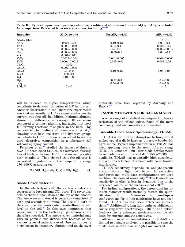
The most common impurities in primary alumina,cryolite and aluminium fluoride are shown inTable III. Since impurities in aluminium fluorideare quite similar to impurities in alumina andcontribute to emissions, AlF3 is included in Table IIIfor completeness. The contributions from bath addi-tions during start-up of new or relined cells are lessimportant. Since solid impurities in the off-gas arecaptured in the GTC, the real impurity level of thealumina (the secondary alumina) added to the cellsis significantly higher than in the primary smelter-grade alumina (SGA).26–28
Several industrial studies show that aluminaadditions are followed by a rapid increase in HFformation.34,35 Hyland, Patterson and Welch36
showed that the smelter-grade alumina is the majorcause for HF generation in the cell, mostly due toadsorbed moisture and hydroxy groups in theunconverted gibbsite. Proposed reactions are:
2AlF3 g or dissð Þ þ 3H2O gð Þ¼ 6HF gð Þ þ Al2O3 s or dissð Þ ð2Þ
3 NaAlF4 gð Þ þ 3H2O gð Þ ¼ 6 HF gð Þ þ Al2O3 sð Þþ Na3AlF6 sð Þ ð3Þ
Thermodynamically, the first one is most likely,although the reactions taking place may differbecause of other oxygen-containing ions in thebath.37,38 LOI (20–300�C) values for secondaryalumina were found to be in the 0.6–2.0% range,depending on humidity.36 In addition, some residualoxyhydroxides bound in other transition aluminas
Table II. Typical elements in anode cokes (ppm byweight unless otherwise stated), extracted fromseveral sources18,20–24
Element Low High Element Low High
Al 20 250 Na 20 140B 1 15 Ni 50 500Ca 20 150 P 5 30Cr 1 50 Pb 3 10Cu 20 50 S, wt.% 0.5 5Fe 50 350 Si 20 250Ga 14 Ti 2 50H, wt.% 0.1 0.15 V 30 500K 10 20 Zn 2 150Mg 50 200Mn 4 100 Ash, wt.% 0.05 0.4Mo 10 20 Volatiles, wt.% 0.1 0.8N, wt.% 0.2 0.4 Moisture, wt.% 0.1 0.4
Aarhaug and Ratvik2970
will be released at higher temperatures, whichcontribute to delayed formation of HF in the cell.Another observation in the laboratory experimentswas that apparently no HF was generated when thecurrent was shut off. In addition, hydrated aluminashowed no difference in average HF emissionscompared to primary alumina, indicating that mostHF-forming reactions take place in the bath. Thiscontradicts the findings of Sommerseth et al.,37
showing that both moisture and hydroxy groupscontribute to HF formation when added to a stan-dard electrolyte composition in a laboratory cellwithout applying current.
Perander et al.39 studied the impact of fines inSGA. Undercalcined SGA causes increased dusting,loss of bath, additional HF formation and possiblybath instability. They showed that the gibbsite isconverted to c-alumina in the temperature range270–300�C according to:
2 � Al OHð Þ3¼ Al2O3 sð Þ þ 2H2O gð Þ ð4Þ
Anode Cover Material
In the electrolysis cell, the carbon anodes arecovered to reduce air and CO2 burn. The cover alsoacts as thermal insulation at the top of the anodes.The anode cover material is generally comprised ofbath and secondary alumina. The use of a bath inthe cover may also contribute to controlling the bathlevel in the cell.40 In this case, impurities thatreport mainly to the bath (e.g., phosphorous) aretherefore recycled. The anode cover material mayvary in particle size distribution because of thevarious types of materials used. Size and impuritydistribution in secondary alumina and anode cover
materials have been reported by Aarhaug andRatvik.41
INSTRUMENTATION FOR GAS ANALYSIS
A wide range of analytical techniques for charac-terization of the off-gas exists. Some of the morecommonly used instruments are presented.
Tuneable Diode Laser Spectroscopy (TDLAS)
TDLAS is an infrared absorption technique thatmakes use of a diode laser as a narrow-bandwidthlight source. Typical implementation of TDLAS hasbeen applying lasers in the near infrared range(NIR, 700–2500 nm), but laser diode developmentshave made the mid-infrared (MIR, 2500–25000 nm)available. TDLAS has potentially high specificity,but requires selection of a band with no or limitedinterference.
TDLAS sensitivity depends on analyte-specificabsorptivity and light path length. In extractiveconfigurations, multi-pass configurations are usedto obtain the desired sensitivity.42 The trade-off forsensitivity is often a loss in dynamics due to theincreased volume of the measurement cell.43
For in-line configurations, the across-duct instal-lation diameter would normally dictate the quan-tification limit. References to multi-passconfigurations for in-line monitoring have not beenfound. TDLAS has also seen extractive applica-tions.44 Additionally, long light paths established incavity ring-down spectroscopy (CRDS) and opticalfeedback cavity enhanced spectroscopy can be uti-lized for extreme analyte sensitivity.
Although most implementations of TDLAS arelimited to a single analyte, it is possible to tune thediode laser so that more analytes are covered.
Table III. Typical impurities in primary alumina, cryolite and aluminium fluoride. Al2O3 in AlF3 is includedfor comparison. Extracted from several sources, including29–33
Impurity Al2O3 (wt.%) Na3AlF6 (wt.%) AlF3 (wt.%)
Al2O3, wt.% 6–9SiO2 0.007–0.02 0.12–0.13 0.001–0.1Fe2O3 0.008–0.022 0.04–0.11 0.005–0.05TiO2 0.002–0.008 0–0.001 0.0008–0.0012CaO 0.003–0.035 0.06–0.1 0.001–0.1ZnO 0.001–0.011V2O5 0.0012–0.004 0.001–0.005 0.0002–0.0003P2O5 0.0004–0.0011 0.015–0.02 0.001–0.02Cr2O3 0.002Ga2O3 0.007–0.008Na2O 0.3–0.45 0.10–0.15 0.05–0.25Li2O 0–0.001K2O 0.01–0.08H2O 0.17–0.3 0.2–0.3SO4 0.54–0.69 0.9–1.5LOI, % 0.4–1 < 1
Aluminium Primary Production Off-Gas Composition and Emissions: An Overview 2971
Fourier-Transform Infrared Spectroscopy(FTIR)
FTIR spectroscopy is a well-established techniquewhere a polychromatic light source is applied typ-ically over the mid-infrared range. A Michelsoninterferometer is used to convert the data collectedfrom time to frequency domain. FTIR is a veryversatile technique that covers many relevant ana-lytes.45 Using multivariate regression, such aspartial least squares (PLS), robust calibration mod-els can be established.
Permanent installations of FTIR instrumentationfor in-line measurement in the aluminium industryhave not been documented. FTIR instrumentationis expensive (unless the application is used for manyanalytes) and has high maintenance requirements(frequent collection of background spectra in inertgas). Establishment of robust calibration models isalso a requirement to limit interference from water,CO2 and SO2.
Gas Chromatography
By application of chromatographic separation ofanalytes through a column, a non-specific detector,such as a thermal conductivity detector (TCD), canbe applied for gas analyte qualification and quan-tification. The limitations of TCD are the sensitivity(typically ppm range) and the need for variouscolumns and carrier gases dependent on theanalyte.
A range of detectors is available for gas chro-matography. In this context, mass spectrometrydetectors (MCDs) are worth mentioning. In additionto the analyte separation given by the chromato-graphic column, the mass spectrometer will furtherresolve gas species with near-identical elutiontimes.
Traditionally, gas chromatographic separation isa slow process with elution times up to 30 min. Withmodern, fast columns, separation times can be aslow as 2–3 min. An inherent problem with columnseparation is a requirement of a ‘‘clean’’ gas: partic-ulates and condensation could potentially clog thecapillary column.
Mass Spectrometry
The availability of commercially process massspectrometers is increasing. Traditionally, electronimpact (EI) ionization has been the dominanttechnique, but also ion molecule reaction (IMR)and selected ion-flow tube (SIFT) ionization tech-niques have become available.
Omitting the gas chromatographic separation, themass spectrometric sensitivity can be significantlyimproved. For EI, deconvolution of overlappingspectral information can be difficult. For primaryaluminium production off-gas, mass to charge line28 sees contributions from N2, CO, CO2 in a waythat makes it difficult to discern N2 from CO, even
with multivariate calibration. This is, however, nota problem for IMR-MS where ionization of N2 can beavoided.
Differential Optical Absorption Spectroscopy(DOAS)
DOAS was established as a technique in order tomonitor atmospheric gas species. A differentialabsorption cross section (cm2 molecule�1) can becalculated by division of the cross section itself witha smoothed fit. In this way, the effect of Raleigh andMie scattering can be eliminated. Also, the require-ment for establishing the incident light intensity iseliminated. Although the listed benefits are nor-mally ascribed to open path configurations, thereare commercial alternatives of DOAS instrumenta-tion for duct installations. DOAS has applications inUV, VIS and IR.
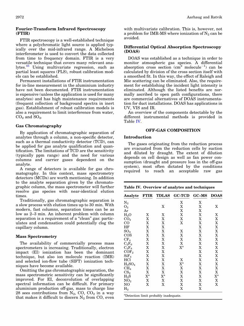
An overview of the components detectable by thedifferent instrumental methods is provided inTable IV.
OFF-GAS COMPOSITION
Introduction
The gases originating from the reduction processare evacuated from the reduction cells by suctionand diluted by draught. The extent of dilutiondepends on cell design as well as fan power con-sumption (draught and pressure loss in the off-gassystem), most often dictated by the conditionsrequired to reach an acceptable raw gas
Table IV. Overview of analytes and techniques
Analyte FTIR TDLAS GC-TCD GC–MS DOAS
N2 X XO2 X X X XAr X XH2O X X X X XCO2 X X X X XCO X X X X XHF X X X XSO2 X X X X XCOS X X X X XCF4 X X X X XC2F6 X X X X XC3F8 X X Xa X XCOF2 X X X XSiF4 X X X XHCl X X X X XH2SO4 X X Xa X XCH4 X X X X XCS2 X X X X XH2S Xa Xa X X Xa
NO2 X X X X XNO X X X X XH2 X X
aDetection limit probably inadequate.
Aarhaug and Ratvik2972

temperature entering the dry scrubber (< 120�C).As a consequence, concentration levels in the off-gasare to a large extent dictated by the amount of airused for cooling, and thus dilution, of the producedgases. In this chapter, gas compounds common tothe aluminium reduction process are presented withan attempt to generalize the off-gas composition.
Carbon Oxides
Carbon oxides are the main gaseous productsfrom reduction of alumina to aluminium. Thedifference in free energy for the formations isreflected by the fact that CO is more stable thanCO2 at a process temperature of about 950�C:46
1
2Al2O3 þ
3
4C ¼ Al þ 3
4CO2 E� ¼ � 1:18 V ð5Þ
1
2Al2O3 þ
3
2C ¼ Al þ 3
2CO E� ¼ � 1:06 V ð6Þ
The main anode reaction has been shown to be theformation of CO2, as the CO-producing route iskinetically hindered. In the presence of solid carbon,CO2 reacts to form CO according to the Boudouardreaction. CO in the off-gas is mainly from air burnand CO2 burn due to insufficient coverage of theanode above the bath. The produced CO2 can alsoreact with produced aluminium metal in a backreaction to form CO and alumina. Hence, theamount of CO depends on the operation of thereduction cell and anode coverage, e.g., a lowinterpolar distance will increase the back reactionand reduce the current efficiency (metalproduction).
The anode gas concentrations of evolved carbonoxides provide important information about theanode reactions and cell operation. Most of thepublished data on carbon oxide gas production are,however, reported from either laboratory-scaleexperiments or experiments where the anode gasis extracted from the cell attempting to avoid theaforementioned reactions of the carbon dioxide gasafter being produced.47–49 Primary aluminium pro-duction off-gas composition, including both the COand CO2 ratios, is, however, scarcely reported.Kimmerle48 reported numbers for CO2 and CO tobe 14,500 and 1340 ppm, respectively. Aarhaug45
reported values of 7700 and 754 ppm for CO2 andCO, respectively. Fleer8 reported CO levels in therange of 500 ppm.
The dry scrubbing of off-gases has little impact onthe carbon oxides as their absorbance on alumina islow. However, for the carbon consumption andenvironmental footprint, the ratio between CO2
and CO is important.
Sulfurous Gas Species
Cokes used in anodes in the reduction of aluminatypically contain between 0.7 wt.% and 3.5 wt.%
sulfur50 with normal levels close to 2%. Most of thesulfur originates from the anodes; however, due tosome adsorption on the primary alumina in the dryscrubber, which is released during addition of thesecondary alumina to the bath, a significant amount ofSO2 in the off-gas can be traced back to this cycle. Onlya small contributionto the sulfur inventory isassumedtooriginate from the primaryalumina.51 In addition tothe emissions of fluorides, the sulfur emissions fromthe process are an environmental issue.
Although SO2 is the main sulfurous compoundemitted from aluminium cells, the sulfur massbalance needs to take several other species intoaccount. Extraction of unreacted anode gas hasshown that COS is the main sulfur gas speciesformed during the reduction of alumina. An elec-trochemical reaction pathway has been proposed byDorreen et al.:52
Al2O3 þ 3C þ 3S ¼ 3COS þ 2AlE� 970 �Cð Þ ¼ � 1:04 V
ð7Þ
Equilibrium constants for the following reactionsalso suggests that COS can be formed by chemicalreaction:52
S þ CO2 þ C ¼ COS þ CO K 970 �Cð Þ ¼ 444 ð8Þ
S þ CO ¼ COS K 970 �Cð Þ ¼ 4:57 ð9Þ
Thermodynamic calculations support that COSreacts in the presence of O2:53
COS þ 3
2O2 ¼ CO2 þ SO2 K 970 �Cð Þ ¼ 7:2 � 1018
ð10Þ
This equilibrium is shifted further to the right atlower temperatures: K (120�C) = 6.3 9 1068, sug-gesting that COS should not be stable in the off-gasat temperatures between 0�C and 1000�C. It isplausible that the reaction kinetics of COS with airis impaired at lower temperatures.
With an anode gas consisting mainly of CO2,reaction of COS with CO2 was evaluated by Utne:54
COS þ 2CO2 ¼ 3CO þ SO2 K 970 �Cð Þ ¼ 7:8 � 10�4
ð11Þ
The equilibrium is shifted further to the left atlower temperatures, K (120�C) = 3.9 9 10�31,53 sug-gesting that COS should be stable even at high CO2
concentrations. Ødegard,55 based on thermody-namic simulations with varying sulfur concentra-tions and temperatures, showed that theconcentration distribution between COS and SO2
is a function of the CO2 to CO ratio in the gas, but atlower temperatures the predominant species isCOS.
Most of the COS is converted to SO2 when the hotanode gas meets the air from the draught to cool thecell gases before entering the ducts. Although COS
Aluminium Primary Production Off-Gas Composition and Emissions: An Overview 2973

has a modest global warming potential (27 in a 100-year perspective), its stability provides transporta-tion of sulfur to the upper atmosphere. Its decom-position is known to produce sulphate aerosols thatboth reflect incoming sunlight and contribute to thedepletion of ozone.56 As a consequence, COS is themost abundant sulfur-containing gas in theatmosphere.
Anode gas characterization involves extraction ofthe gases to a gas analyser. Analysis is oftenperformed at a gas temperature between 50�C and300�C. The speciation in the gas may be affected bythe cooling of the gas. Experimental data clearlyshow that COS is the dominating sulfurous gasspecies when oxidation is avoided.48,49,52,54,55
Although the gas species H2S and CS2 are fre-quently reported in small amounts in the anode gas,it is only occasionally reported for duct gas mea-surements. Most likely the observed CS2 (and H2S)is a result of decomposition of COS at intermediatetemperatures (350–600�C).57 Sulfurous species inthe off-gas are less frequently reported than theCO2/CO ratio. A summary of the reported data isfound in Table V.
Tveito58 also analysed COS and H2S before andafter the dry and wet scrubbers. The results indi-cate low scrubbing efficiencies for these gases.
The formation of sulfuric acid in the primaryaluminium off-gas has generally not been a problemwith respect to corrosion of duct materials. Thethermodynamics of possible formation mechanismsfor H2SO4 is illustrated in Fig. 2, where data fromOkkes and Bagder have been used.59
SO3 formation is generally formed by oxidation ofSO2. The conversion efficiency is not well under-stood, and values between 1% to 5% are oftenassumed.60 In sulfuric acid production, the conver-sion of SO2 to SO3 is accelerated by catalyticconversion at temperatures in the range of 350–400�C. The observed variations in the amount ofSO3 formed may be an effect of variations in metalimpurities in the anodes,61 as these are frequentlyobserved as particulates in the off-gas, e.g., Fe, Niand V compounds. SO3 is very hygroscopic and, onceformed, it will react stoichiometrically with humid-ity to form sulfuric acid at temperatures below400�C.
In future design of aluminium smelters, theoption to recover heat from the duct gas isinevitable. To optimise heat exchanger efficiency, ahotter and more concentrated off-gas is required.With increased concentrations of SO2, the conden-sation of sulfuric acid may occur at the cold surfacesof a heat exchanger. Assessment of the acid dewpoint is often done by open path spectroscopy.Aarhaug45 applied FTIR spectroscopy across anindustrial-scale reduction cell to detect SO3 andH2SO4. An acid dew point value in the range 40–80�C has often been assumed for aluminium pro-duction. By using equations that correlate the aciddew point with the SO3 concentration,59,62 anestimate was calculated using the relevant humid-ity and fan draught parameters. Even though thesensitivity of the FTIR spectrometer was assumedsufficient, the only sulfurous species detected wereSO2 and COS. It is speculated whether SO3 adsorp-tion onto particulates can effectively lower the SO3
concentration in the gas phase.52 One likely option
Table V. Duct off-gas compositions found in the literature. All numbers are in ppm mol
Gas Kimmerle48 Aarhaug45 Utne54 Utne54 Tveito58
GC–MS FTIR GC-FPD GC-FPD GCPrebake Prebake Prebake Soderberg Prebake
SO2 135 67 44 284 63COS 6.4 6.8 16 11 2.6CS2 0.13 0.69H2S 1.5CO2 12,050 7700CO 1330 755
Fig. 2. Thermodynamics of the formation of sulfuric acid from SO2
(plotted from data in Ref. 59).
Aarhaug and Ratvik2974

is that SO2 is adsorbed on particulates where it isconverted to SO3, which reacts to sulphates. Theobservation of sulphates in the particulates from theoff-gas8,9 suggests an interaction between gaseoussulfur species and the particulates.
Fluorides
The off-gas from primary aluminium containsfluorides in both gaseous and particulate form. Dueto the strong environmental impact of fluoride emis-sions, dry scrubbing technologies are universallyapplied. Today’s dry scrubbers operate with recoveryof fluorides > 99%. Fluoride is considered a recov-ered valuable. By returning fluorides to the elec-trolyte, less aluminium fluoride needs to be added.
Hydrogen fluoride is the most abundant fluoridegas species in the off-gas. It is formed by reactionwith fluorides in the bath or vapour phase accordingto reactions:44,63
2AlF3 dissð Þ þ 3H2O g or dissð Þ¼ 6 HF gð Þ þ Al2O3 dissð Þ ð12Þ
3NaAlF4 g,sð Þ þ 3H2O gð Þ ¼ 6HF gð Þ þ Na3AlF6 sð Þþ Al2O3 sð Þ
ð13Þ
3Na5Al3F14 g,sð Þ þ 6H2O gð Þ¼ 12 HF gð Þ þ 5Na3AlF6 sð Þ þ 2 Al2O3 sð Þ ð14Þ
Water is available from the humidity in air butalso the structural hydroxy groups in the primaryalumina.38,64 In addition, HF may form from thehydrogen content of the anode, where an electrolyticreaction has been proposed:63
2AlF3 dissð Þ þ 3H2 gð Þ ¼ 6HF gð Þ þ 2Al lð Þ ð15Þ
The vaporization of the electrolyte releasesNaAlF4 to the off-gas.65 The stability of this specieshas been much discussed, and a disproportionationinto solid chiolite and aluminium fluoride has beenproposed.66 Nevertheless, the above hydrolysis reac-tions suggest that all the fluoride species, in eithergaseous or condensed form, can react. NaAlF4 hasbeen reported in the condensed phase by Gaertner.9
It has been established that gaseous fluoridespecies comprise approximately 50% of the totalfluoride content in the off-gas.67,68 Several factorsinfluence this ratio, crust integrity being one of thefactors for evaporation of bath. Interestingly, sea-sonal changes in this ratio occur: higher air humid-ity levels in summer appear to increase hydrolysis,thus increasing the ratio of HF to particulatefluorides.63
As dry scrubbing technologies have become morethan 99% efficient, the main source of fluorideemissions is now fugitive.69 Two gaseous fluorine-containing species that, however, do pass throughthe dry (and wet) scrubbers are tetrafluoromethane
(CF4) and hexafluoroethane (C2F6). The formationof fluorocarbons in primary aluminium productionoccurs at the anode when the local consumption ofalumina becomes higher than the supply, reducingthe local concentration of alumina to allow compet-itive anode reactions. For a constant current oper-ation with anodes interconnected, the PFCformation on individual anodes can be seen as ashift in electrolytic resistance into anode overvolt-age. Propagation of a local anode effect to a full cellanode effect can be seen as a result of higher currentdensity at the anodes not depleted of alumina,which eventually becomes higher than the criticalcurrent density for CF4 and C2F6 formation.
The most abundant PFC, tetrafluoromethane, isformed from the following reaction:52
4Na3AlF6 þ 3C ¼ 12NaF þ 4Al þ 3CF4
E� 970 �Cð Þ ¼ � 2:54 Vð16Þ
And similarly, hexafluoroethane:
2Na3AlF6 þ 2C ¼ 6NaF þ 2Al þ C2F6
E� 970 �Cð Þ ¼ � 2:78 Vð17Þ
Although their contribution to the fluorine inven-tory is modest, their environmental impact is largewith global warming potentials (GWP) in a 100-yearperspective of 7390 and 12,200 for CF4 and C2F6,respectively.70
Theoretically, an intermediate may be formed atlower voltages:
2Na3AlF6 þ Al2O3 þ 3C ¼ 6NaF þ 2Al þ 3COF2
E� 970 �Cð Þ ¼ � 1:86 V
ð18Þ
While formation of COF2 is favourable thermody-namically, this species has only been reported oncein laboratory-scale experiments with inert gas.52 Anattempt to reproduce this experiment was notsuccessful.71 It has been suggested that COF2 isunstable and will either react with carbon to formPFC’s52 or self-disproportionate to form CF4 andCO2. Evidence of CF4 formation at low voltages maysupport an intermediate formation of COF2 followedby decomposition into CF4.43,71 In industrial-scaleelectrolysis, COF2 is believed to decompose into HFand CO2 and is thus not present in the duct. In abeam-through cell experiment with open-path spec-troscopy, only traces of COF2 have been identified.45
Historically, high PFC emissions were experi-enced during the start-up of electrolysis cells.Today, start-up protocols are aiming at minimizingthe PFC emissions by means of proper pre-heatingof the cells.72,73
SUMMARY
Several efforts have been made to relate raw gascomposition and cell emissions to operationalparameters. The present article presents a general
Aluminium Primary Production Off-Gas Composition and Emissions: An Overview 2975

overview; however, many factors are still uncertainand some may even be speculative. For instance, agood overview of secondary reactions and dilutionvariations by draught is still not well documented.Although the impurities in the raw materials arewell documented, a good material balance or mate-rial flow during operation is lacking for manyelements. Hence, the reported data are insufficientfor performing a proper mass balance of the gascomposition. As improved and more affordablestate-of-the-art techniques for gas characterizationhave emerged, the ability to better relate observa-tions to process conditions is promising. This may beeven more important as the industry develops moreenergy-efficient reduction technology, e.g., by reduc-ing the amount of draught used for cooling incombination with energy recovery from the raw gas.To be able to incorporate technology changes of thistype, more detailed knowledge about the off-gascomposition is required as limiting factors such asscale formation and acid dew points must beconsidered.
ACKNOWLEDGEMENTS
Funding was provided by Norges Forskningsrad(237738).
OPEN ACCESS
This article is distributed under the terms of theCreative Commons Attribution 4.0 International Li-cense (http://creativecommons.org/licenses/by/4.0/),which permits unrestricted use, distribution, andreproduction in any medium, provided you giveappropriate credit to the original author(s) and thesource, provide a link to the Creative Commons li-cense, and indicate if changes were made.
REFERENCES
1. W.D. Lamb, Light Met. 1979, 889 (1979).2. N. Tjahyono, Y. Gao, D. Wong, W. Zhang, and M.P. Taylor,
Light Met. 2011, 301 (2011).3. A.V. Mikhonin, N.R. Dando, and M. Gershenzon, Light Met.
2013, 905 (2013).4. S.O. Strømmen, E. Bjørnstad, and G. Wedde, Light Met.
2000, 351 (2000).5. S.J. Lindsay, N.R. Dando, and S. Broek, Light Met. 2017,
487 (2017).6. N.R. Dando and S.J. Lindsay, Light Met. 2016, 527 (2016).7. M.B. Mitchell, V.N. Sheinker, and M.G. White, J. Phys.
Chem. 100, 7550 (1996).8. M. Fleer, O.-A. Lorentsen, W. Harvey, H. Palsson, and G.
Saevarsdottir, Light Met. 2010, 243 (2010).9. H. Gaertner, Ph.D. dissertation, Norwegian University of
Science and Technology (2013).10. D.S. Wong, N.I. Tjahyono, and M.M. Hyland, Light Met.
2014, 553 (2014).11. H. Kvande and P.A. Drabløs, J. Occup. Environ. Med. 56,
S23 (2014).12. A. Sørhuus and S. Ose, Light Met. 2017, 495 (2017).13. A. Sørhuus, S. Ose, and E. Holmefjord, Light Met. 2018, 655
(2018).14. A. Sørhuus, G. Wedde, K. Rye, and G. Nyland, Light Met.
2010, 249 (2010).15. S.J. Lindsay, Light Met. 2013, 5 (2013).16. W. Boenigk, C. Boltersdorf, C. Kuhnt, J. Stiegert, L. Ed-
wards, and M. Lubin, Light Met. 2015, 1033 (2015).
17. S. Gao, C. Bao, B. Xia, R. Lin, J. Woo, G. Lang, and E.Cutshall, Light Met. 2014, 1105 (2014).
18. A. Sarkar, D. Kocaefe, D. Bhattacharyay, B. Morais, andC.L. Lagace, Light Met. 2014, 1099 (2014).
19. K. Neyrey, L. Edwards, and J. Marino, Light Met. 2013,1051 (2013).
20. S. Birghila, I.C. Popovici, and A. Dumitru, Rom. J. Phys. 56,976 (2011).
21. B. Monsen, A.P. Ratvik, and L.P. Lossius, Light Met. 2010,929 (2010).
22. L.C. Edwards, 11th AASTC 2014, Paper 08Key2 (2014).23. L.C. Edwards, 10th AASTC 2011, Paper 2a1 (2011).24. K. Khaji and M. Al Qassemi, Metals 2016, 128 (2016).25. N.R. Dando, Light Met. 2005, 133 (2005).26. L.P. Lossius and H.A. Øye, JOM 43, 41 (1991).27. S. Kalyavina, A.P. Ratvik, and T. Aarhaug, Light Met. 2013,
195 (2013).28. H. Gaertner, A.P. Ratvik, and T.A. Aarhaug, Light Met.
2013, 769 (2013).29. J. Thonstad, P. Fellner, G.M. Haarberg, J. Hıves, H.
Kvande, and A. Sterten, Aluminium Electrolysis: Funda-mentals of the Hall-Heroult Process (Dusseldorf: Alu-minium-Verlag, 2001) (Ch. 10).
30. S.J. Lindsay, 9th AASTC 2007 (2007), p. 05.31. P. Homsi, 6th AASTC 1998 (1998), p. 73.32. A. Suss, A. Senyuta, M. Kravchenya, A. Smirnov, and A.
Panov, ICSOBA 2015, Paper AA16 (2015).33. D.V. Finin, M.A. Kravchenya, T.D. Pecherskaya, and A.V.
Panov, Aluminium of Siberia, Proceedings XII (2006).34. M.L. Slaugenhaupt, J.N. Bruggeman, G.P. Tarcy, and N.R.
Dando, Light Met. 2003, 199 (2003).35. C. Sommerseth, K.S. Osen, T.A. Aarhaug, E. Skybakmoen,
A. Solheim, C. Rosenkilde, and A.P. Ratvik, Light Met. 2011,339 (2011).
36. M. Hyland, E. Patterson, and B. Welch, Light Met. 2004, 361(2004).
37. C. Sommerseth, K. Sende Osen, C. Rosenkilde, A.M. Meyer,L.T. Kristiansen, and T.A. Aarhaug, Light Met. 2012, 827(2012).
38. W.E. Haupin and H. Kvande, Light Met. 1993, 257 (1993).39. L. Perander, Z. Zujovic, T. Kemp, M. Smith, and J.B. Met-
son, JOM 61, 33 (2009).40. S. Wilkening, P. Reny, and B. Murphy, Light Met. 2005, 367
(2005).41. T.A. Aarhaug and A.P. Ratvik, Report No. SINTEF F17251
(2010).42. H. Gamble, D.R. Karecki, G.I. Mackay, and H. Schiff, Light
Met. 2003, 215 (2003).43. H. Asheim, T.A. Aarhaug, A. Ferber, O.S. Kjos, and G.M.
Haarberg, Light Met. 2014, 535 (2014).44. K.S. Osen, T.A. Aarhaug, A. Solheim, E. Skybakmoen, and
C. Sommerseth, Light Met. 2011, 263 (2011).45. T.A. Aarhaug, A. Ferber, O. Kjos, and H. Gaertner, Light
Met. 2014, 647 (2014).46. J. Thonstad, P. Fellner, G.M. Haarberg, J. Hıves, H.
Kvande, and A. Sterten, Aluminium Electrolysis—Funda-mentals of the Hall-Heroult Process, 3rd ed. (Dusseldorf:Aluminium Verlag, 2001).
47. J. Thonstad, J. Electrochem. Soc. 111, 959 (1964).48. F.M. Kimmerle and L. Noel, Light Met. 1997, 153 (1997).49. T.A. Aarhaug, O.S. Kjos, H. Gudbrandsen, A. Ferber, and
A.P. Ratvik, Light Met. 2016, 533 (2016).50. M. Ambrova, P. Fellner, J. Gabkova, and A. Sykorova,
Chem. Pap. 59, 235 (2005).51. J. Thonstad, I. Utne, K.A. Paulsen, and G. Svendsen, 6th
AASTC 1998 (1998), p. 369.52. M.M.R. Dorreen, D.L. Chin, J.K.C. Lee, M.M. Hyland, and
B.J. Welch, Light Met. 1998, 311 (1998).53. A. Roine, T. Kotiranta, H. Eerola, and P. Lamberg, HSC
Chemistry 7.1 (Espoo: Outotec, 2011).54. I. Utne, K.A. Paulsen, and J. Thonstad, Light Met. 1998, 293
(1998).55. R. Ødegard, S. Rønning, A. Sterten, and J. Thonstad, Light
Met. 1985, 661 (1985).
Aarhaug and Ratvik2976
56. J. Dippell and W. Jaeshke, J. Atmos. Chem. 25, 251 (1996).57. K. Karan, A.K. Mehrotra, and L.A. Behie, Chem. Eng.
Commun. 192, 370 (2005).58. K. Tveito, J. Tonheim, K.A. Paulsen, and J. Thonstad, Pre-
sented at the 40th Annual Conference of Metallurgists ofCIM, Torono, 2001 (unpublished).
59. A.G. Okkes and B.V. Badger, Hydrocarb. Process. 66, 53(1987).
60. K.B. Schnelle and C.A. Brown, Air Pollution Control Tech-nology Handbook (London: CRC Press, 2002).
61. L.P. Belo, L.K. Elliot, R.J. Stanger, R. Sporl, K.V. Shah, J.Maier, and T.F. Wall, Energy Fuels 28, 7243 (2014).
62. F.H. Verkhoff and J.T. Banchero, Chem. Eng. Prog. 70, 71(1974).
63. M.M. Hyland, B.J. Welch, and J.B. Metson, Light Met. 2000,333 (2000).
64. W.E. Wahnsiedler, R.S. Danchik, W.E. Haupin, D.L.Brackenstose, and J.W. Colpitts, Light Met. 1978, 407(1978).
65. H. Kvande, Dr. Techn. Dissertation, NTH (1979).66. O. Bjørseth, O. Herstad, and J.L. Holm, Acta Chem. Scand.
A 40, 566 (1986).67. K. Grjotheim, H. Kvande, K. Motzfeldt, and B. Welch, Can.
Metall. Q. 11, 585 (1972).68. P. Jones and E. Keul, Light Met. 1991, 509 (1991).69. E. Sum, 6th AASTC 1998 (1998), p. 667.70. IPCC Fifth Assessment Report, edited by R.K. Pachauri and
L.A. Meyer (2014).71. O.S. Kjos, T.A. Aarhaug, E. Skybakmoen, and A. Solheim,
Light Met. 2012, 623 (2012).72. O.-A. Lorentsen, and K.A. Rye, Light Met. 2008, 1001
(2008).73. K.A. Rye, Light Met. 2008, 1007 (2008).
Publisher’s Note Springer Nature remains neutral with re-gard to jurisdictional claims in published maps and institutionalaffiliations.
Aluminium Primary Production Off-Gas Composition and Emissions: An Overview 2977